KR102269599B1 - Image pickup apparatus including lens elements having different diameters - Google Patents
Image pickup apparatus including lens elements having different diametersDownload PDFInfo
- Publication number
- KR102269599B1 KR102269599B1KR1020140048873AKR20140048873AKR102269599B1KR 102269599 B1KR102269599 B1KR 102269599B1KR 1020140048873 AKR1020140048873 AKR 1020140048873AKR 20140048873 AKR20140048873 AKR 20140048873AKR 102269599 B1KR102269599 B1KR 102269599B1
- Authority
- KR
- South Korea
- Prior art keywords
- lens element
- imaging
- image
- lens elements
- pixel pitch
- Prior art date
- Legal status (The legal status is an assumption and is not a legal conclusion. Google has not performed a legal analysis and makes no representation as to the accuracy of the status listed.)
- Active
Links
Images


Classifications
- G—PHYSICS
- G02—OPTICS
- G02B—OPTICAL ELEMENTS, SYSTEMS OR APPARATUS
- G02B13/00—Optical objectives specially designed for the purposes specified below
- G02B13/001—Miniaturised objectives for electronic devices, e.g. portable telephones, webcams, PDAs, small digital cameras
- G02B13/0015—Miniaturised objectives for electronic devices, e.g. portable telephones, webcams, PDAs, small digital cameras characterised by the lens design
- H—ELECTRICITY
- H04—ELECTRIC COMMUNICATION TECHNIQUE
- H04N—PICTORIAL COMMUNICATION, e.g. TELEVISION
- H04N23/00—Cameras or camera modules comprising electronic image sensors; Control thereof
- H04N23/60—Control of cameras or camera modules
- H04N23/69—Control of means for changing angle of the field of view, e.g. optical zoom objectives or electronic zooming
- G—PHYSICS
- G02—OPTICS
- G02B—OPTICAL ELEMENTS, SYSTEMS OR APPARATUS
- G02B13/00—Optical objectives specially designed for the purposes specified below
- G02B13/001—Miniaturised objectives for electronic devices, e.g. portable telephones, webcams, PDAs, small digital cameras
- G—PHYSICS
- G02—OPTICS
- G02B—OPTICAL ELEMENTS, SYSTEMS OR APPARATUS
- G02B13/00—Optical objectives specially designed for the purposes specified below
- G02B13/001—Miniaturised objectives for electronic devices, e.g. portable telephones, webcams, PDAs, small digital cameras
- G02B13/009—Miniaturised objectives for electronic devices, e.g. portable telephones, webcams, PDAs, small digital cameras having zoom function
- G—PHYSICS
- G02—OPTICS
- G02B—OPTICAL ELEMENTS, SYSTEMS OR APPARATUS
- G02B27/00—Optical systems or apparatus not provided for by any of the groups G02B1/00 - G02B26/00, G02B30/00
- G02B27/10—Beam splitting or combining systems
- G02B27/1066—Beam splitting or combining systems for enhancing image performance, like resolution, pixel numbers, dual magnifications or dynamic range, by tiling, slicing or overlapping fields of view
- G—PHYSICS
- G02—OPTICS
- G02B—OPTICAL ELEMENTS, SYSTEMS OR APPARATUS
- G02B27/00—Optical systems or apparatus not provided for by any of the groups G02B1/00 - G02B26/00, G02B30/00
- G02B27/10—Beam splitting or combining systems
- G02B27/12—Beam splitting or combining systems operating by refraction only
- G02B27/123—The splitting element being a lens or a system of lenses, including arrays and surfaces with refractive power
- G—PHYSICS
- G02—OPTICS
- G02B—OPTICAL ELEMENTS, SYSTEMS OR APPARATUS
- G02B3/00—Simple or compound lenses
- G02B3/0006—Arrays
- G02B3/0037—Arrays characterized by the distribution or form of lenses
- G02B3/0043—Inhomogeneous or irregular arrays, e.g. varying shape, size, height
- H—ELECTRICITY
- H04—ELECTRIC COMMUNICATION TECHNIQUE
- H04M—TELEPHONIC COMMUNICATION
- H04M1/00—Substation equipment, e.g. for use by subscribers
- H04M1/02—Constructional features of telephone sets
- H04M1/0202—Portable telephone sets, e.g. cordless phones, mobile phones or bar type handsets
- H04M1/026—Details of the structure or mounting of specific components
- H04M1/0264—Details of the structure or mounting of specific components for a camera module assembly
- H—ELECTRICITY
- H04—ELECTRIC COMMUNICATION TECHNIQUE
- H04N—PICTORIAL COMMUNICATION, e.g. TELEVISION
- H04N23/00—Cameras or camera modules comprising electronic image sensors; Control thereof
- H04N23/45—Cameras or camera modules comprising electronic image sensors; Control thereof for generating image signals from two or more image sensors being of different type or operating in different modes, e.g. with a CMOS sensor for moving images in combination with a charge-coupled device [CCD] for still images
- H—ELECTRICITY
- H04—ELECTRIC COMMUNICATION TECHNIQUE
- H04N—PICTORIAL COMMUNICATION, e.g. TELEVISION
- H04N23/00—Cameras or camera modules comprising electronic image sensors; Control thereof
- H04N23/50—Constructional details
- H04N23/54—Mounting of pick-up tubes, electronic image sensors, deviation or focusing coils
- H—ELECTRICITY
- H04—ELECTRIC COMMUNICATION TECHNIQUE
- H04N—PICTORIAL COMMUNICATION, e.g. TELEVISION
- H04N23/00—Cameras or camera modules comprising electronic image sensors; Control thereof
- H04N23/57—Mechanical or electrical details of cameras or camera modules specially adapted for being embedded in other devices
- H—ELECTRICITY
- H04—ELECTRIC COMMUNICATION TECHNIQUE
- H04N—PICTORIAL COMMUNICATION, e.g. TELEVISION
- H04N23/00—Cameras or camera modules comprising electronic image sensors; Control thereof
- H04N23/60—Control of cameras or camera modules
- H—ELECTRICITY
- H04—ELECTRIC COMMUNICATION TECHNIQUE
- H04N—PICTORIAL COMMUNICATION, e.g. TELEVISION
- H04N23/00—Cameras or camera modules comprising electronic image sensors; Control thereof
- H04N23/95—Computational photography systems, e.g. light-field imaging systems
- H04N23/951—Computational photography systems, e.g. light-field imaging systems by using two or more images to influence resolution, frame rate or aspect ratio
- H—ELECTRICITY
- H04—ELECTRIC COMMUNICATION TECHNIQUE
- H04N—PICTORIAL COMMUNICATION, e.g. TELEVISION
- H04N25/00—Circuitry of solid-state image sensors [SSIS]; Control thereof
- H04N25/70—SSIS architectures; Circuits associated therewith
- H04N25/703—SSIS architectures incorporating pixels for producing signals other than image signals
- H04N25/704—Pixels specially adapted for focusing, e.g. phase difference pixel sets
- H—ELECTRICITY
- H04—ELECTRIC COMMUNICATION TECHNIQUE
- H04N—PICTORIAL COMMUNICATION, e.g. TELEVISION
- H04N13/00—Stereoscopic video systems; Multi-view video systems; Details thereof
- H04N13/20—Image signal generators
- H04N13/204—Image signal generators using stereoscopic image cameras
- H04N13/239—Image signal generators using stereoscopic image cameras using two 2D image sensors having a relative position equal to or related to the interocular distance
- H—ELECTRICITY
- H04—ELECTRIC COMMUNICATION TECHNIQUE
- H04N—PICTORIAL COMMUNICATION, e.g. TELEVISION
- H04N13/00—Stereoscopic video systems; Multi-view video systems; Details thereof
- H04N13/20—Image signal generators
- H04N13/204—Image signal generators using stereoscopic image cameras
- H04N13/243—Image signal generators using stereoscopic image cameras using three or more 2D image sensors
Landscapes
- Physics & Mathematics (AREA)
- Engineering & Computer Science (AREA)
- Signal Processing (AREA)
- Multimedia (AREA)
- General Physics & Mathematics (AREA)
- Optics & Photonics (AREA)
- Theoretical Computer Science (AREA)
- Human Computer Interaction (AREA)
- Computing Systems (AREA)
- Studio Devices (AREA)
- Transforming Light Signals Into Electric Signals (AREA)
- Cameras In General (AREA)
- Lenses (AREA)
Abstract
Translated fromKoreanDescription
Translated fromKorean개시된 실시예들은 직경이 서로 다른 렌즈 소자들을 구비하는 촬상 장치에 관한 것으로서, 더욱 상세하게는 직경이 서로 다른 다수의 렌즈 소자들을 사용함으로써 두께의 증가 없이 줌 기능을 수행하는 동시에 깊이 정보를 획득할 수 있는 촬상 장치에 관한 것이다.The disclosed embodiments relate to an imaging device having lens elements having different diameters, and more particularly, by using a plurality of lens elements having different diameters, it is possible to obtain depth information while performing a zoom function without increasing the thickness. It relates to an imaging device.
휴대전화와 같은 모바일 장치의 두께는 계속해서 감소하는 추세이며, 이에 따라 모바일 장치 내에 장착된 카메라의 광학계에 대한 두께 감소가 요구되고 있다. 광학계의 두께 감소가 감소하면 광학계의 초점 거리가 짧아지게 되며, 그에 따라 이미지 센서의 크기도 역시 작아지게 되는데, 이로 인하여 영상의 화질이 열화될 수 있다. 이미지 센서의 크기가 작아지면 이미지 센서 내의 화소의 개수가 줄어들기 때문이다. 그러나 이미지 센서의 크기가 작아지더라도 이미지 센서의 화소가 그만큼 작아지면 고해상도의 영상을 얻을 수 있다. 이에 따라 이미지 센서의 화소 피치를 줄이기 위한 노력이 이루어지고 있다. 예를 들어, 현재 이미지 센서의 화소 피치는 약 1um 수준까지 감소되었다.The thickness of a mobile device such as a mobile phone is continuously decreasing, and accordingly, a reduction in the thickness of an optical system of a camera mounted in the mobile device is required. When the thickness of the optical system is reduced, the focal length of the optical system is shortened, and accordingly, the size of the image sensor is also reduced, which may deteriorate image quality. This is because when the size of the image sensor decreases, the number of pixels in the image sensor decreases. However, even if the size of the image sensor is reduced, if the pixels of the image sensor are reduced that much, high-resolution images can be obtained. Accordingly, efforts are being made to reduce the pixel pitch of the image sensor. For example, the pixel pitch of current image sensors has been reduced to the level of about 1 um.
한편, 모바일 장치의 카메라는 두께에 제한이 있기 때문에, 아직까지 초점거리가 가변인 줌 렌즈를 채용하지 못하고 초점거리가 짧은 단초점 렌즈를 대체로 사용하고 있다. 이로 인해 모바일 장치의 카메라는 줌 기능을 제공하기가 어렵다. 현재, 모바일 장치의 카메라에 채용된 줌 기능은 대부분 광학적 줌 기능이 아닌 디지털 줌 기능이다. 즉, 촬상된 원본 영상의 일부를 단순히 신호처리적으로 확대하는 방식이기 때문에 확대된 영상의 화각이 좁아질수록 화질이 나빠지게 된다.On the other hand, since a camera of a mobile device has a limited thickness, a zoom lens having a variable focal length has not yet been adopted, but a short focal length lens is generally used. Due to this, it is difficult for the camera of the mobile device to provide a zoom function. Currently, most zoom functions employed in cameras of mobile devices are digital zoom functions, not optical zoom functions. That is, since a part of the captured original image is simply enlarged by signal processing, the image quality deteriorates as the angle of view of the enlarged image becomes narrower.
두께의 증가 없이 줌 기능을 수행하는 동시에 깊이 정보를 획득할 수 있는 촬상 장치를 제공한다.An imaging device capable of acquiring depth information while performing a zoom function without increasing thickness is provided.
일 실시예에 따른 촬상 장치는, 적어도 2개의 렌즈 소자; 및 상기 적어도 2개의 렌즈 소자들에 각각 대응하여 배치된 적어도 2개의 촬상 영역;을 포함할 수 있으며, 여기서 상기 적어도 2개의 렌즈 소자들 중에서 일부가 서로 다른 직경을 갖고, 상기 적어도 2개의 촬상 영역들 중에서 일부가 서로 다른 크기를 가지며, 상기 적어도 2개의 렌즈 소자들 중에서 직경이 가장 큰 렌즈 소자에 대해 크기가 가장 작은 촬상 영역이 배치되고, 상기 적어도 2개의 렌즈 소자들 중에서 직경이 가장 작은 렌즈 소자에 대해 크기가 가장 큰 촬상 영역이 배치될 수 있다.An imaging device according to an embodiment includes at least two lens elements; and at least two imaging regions respectively disposed to correspond to the at least two lens elements, wherein some of the at least two lens elements have different diameters, and the at least two imaging regions Some of them have different sizes, and an imaging area having the smallest size is disposed for a lens element having the largest diameter among the at least two lens elements, and a lens element having the smallest diameter among the at least two lens elements. An imaging area having the largest size may be disposed.
일 실시예에서, 상기 적어도 2개의 촬상 영역들은 각각 물리적으로 분리된 별개의 이미지 센서를 포함할 수 있다.In an embodiment, each of the at least two imaging areas may include a separate physically separated image sensor.
상기 적어도 2개의 촬상 영역들 중에서 일부가 서로 다른 화소 피치를 가지며, 각각의 촬상 영역에 대응하는 렌즈 소자의 직경이 클수록 상기 촬상 영역의 화소 피치가 작아지고, 각각의 촬상 영역에 대응하는 렌즈 소자의 직경이 작을수록 상기 촬상 영역의 화소 피치가 커질 수 있다.Some of the at least two imaging regions have different pixel pitches, and the larger the diameter of the lens element corresponding to each imaging region, the smaller the pixel pitch of the imaging region, and the lens element corresponding to each imaging region. As the diameter decreases, the pixel pitch of the imaging area may increase.
다른 실시예에서, 상기 적어도 2개의 촬상 영역들은 하나의 이미지 센서 내에서 논리적으로 분할된 영역들일 수 있다.In another embodiment, the at least two imaging regions may be logically divided regions within one image sensor.
상기 적어도 2개의 렌즈 소자들 중에서 직경이 서로 다른 렌즈 소자들은 상기 적어도 2개의 촬상 영역들 상에 각각 서로 다른 크기의 광스폿을 형성하도록 구성될 수 있다.Among the at least two lens elements, lens elements having different diameters may be configured to form light spots having different sizes on the at least two imaging areas, respectively.
상기 촬상 장치는, 상기 적어도 2개의 렌즈 소자들 및 그에 각각 대응하는 적어도 2개의 촬상 영역들을 이용하여 취득한 적어도 2개의 영상들로부터 깊이 정보를 추출하도록 구성될 수 있다.The imaging device may be configured to extract depth information from at least two images acquired using the at least two lens elements and at least two imaging areas corresponding thereto, respectively.
일 실시예에서, 상기 적어도 2개의 렌즈 소자들은 제 1 직경을 갖는 제 1 렌즈 소자, 제 1 직경보다 큰 제 2 직경을 갖는 제 2 렌즈 소자, 및 제 2 직경보다 큰 제 3 직경을 갖는 제 3 렌즈 소자를 포함할 수 있으며, 상기 적어도 2개의 촬상 영역들은 상기 제 1 렌즈 소자에 대응하며 제 1 크기를 갖는 제 1 촬상 영역, 상기 제 2 렌즈 소자에 대응하며 제 1 크기를 갖는 제 2 촬상 영역, 및 상기 제 3 렌즈 소자에 대응하며 제 1 크기보다 작은 제 2 크기를 갖는 제 3 촬상 영역을 포함할 수 있고, 상기 제 1 촬상 영역은 제 1 화소 피치를 갖고, 제 2 촬상 영역은 제 1 화소 피치보다 작은 제 2 화소 피치를 가지며, 제 3 촬상 영역은 제 2 화소 피치보다 작은 제 3 화소 피치를 가질 수 있다.In one embodiment, the at least two lens elements comprise a first lens element having a first diameter, a second lens element having a second diameter greater than the first diameter, and a third lens element having a third diameter greater than the second diameter. a lens element, wherein the at least two imaging areas are a first imaging area corresponding to the first lens element and having a first size, and a second imaging area corresponding to the second lens element and having a first size. , and a third imaging area corresponding to the third lens element and having a second size smaller than the first size, wherein the first imaging area has a first pixel pitch, and the second imaging area includes a first The second pixel pitch may be smaller than the pixel pitch, and the third imaging area may have a third pixel pitch smaller than the second pixel pitch.
다른 실시예에서, 상기 적어도 2개의 렌즈 소자들은 제 1 직경을 갖는 제 1 렌즈 소자, 제 1 직경을 갖는 제 2 렌즈 소자, 및 제 1 직경보다 큰 제 2 직경을 갖는 제 3 렌즈 소자를 포함하고, 상기 적어도 2개의 촬상 영역들은 상기 제 1 렌즈 소자에 대응하며 제 1 크기를 갖는 제 1 촬상 영역, 상기 제 2 렌즈 소자에 대응하며 제 1 크기를 갖는 제 2 촬상 영역, 및 상기 제 3 렌즈 소자에 대응하며 제 1 크기보다 작은 제 2 크기를 갖는 제 3 촬상 영역을 포함하며, 상기 제 1 및 제 2 촬상 영역은 제 1 화소 피치를 갖고, 상기 제 3 촬상 영역은 제 1 화소 피치보다 작은 제 2 화소 피치를 가질 수 있다.In another embodiment, the at least two lens elements comprise a first lens element having a first diameter, a second lens element having a first diameter, and a third lens element having a second diameter greater than the first diameter , the at least two imaging regions are a first imaging region corresponding to the first lens element and having a first size, a second imaging region corresponding to the second lens element and having a first size, and the third lens element a third imaging area corresponding to and having a second size smaller than the first size, wherein the first and second imaging areas have a first pixel pitch, and wherein the third imaging area has a second size smaller than the first pixel pitch. It may have a 2 pixel pitch.
상기 제 2 렌즈 소자와 제 3 렌즈 소자 사이에 상기 제 1 렌즈 소자가 배치되고, 상기 제 2 촬상 영역과 제 3 촬상 영역 사이에 상기 제 1 촬상 영역이 배치될 수 있다.The first lens element may be disposed between the second lens element and the third lens element, and the first imaging area may be disposed between the second imaging area and the third imaging area.
상기 제 1 렌즈 소자와 제 2 렌즈 소자 사이에 상기 제 3 렌즈 소자가 배치되고, 상기 제 1 촬상 영역과 제 2 촬상 영역 사이에 상기 제 3 촬상 영역이 배치될 수도 있다.The third lens element may be disposed between the first lens element and the second lens element, and the third imaging area may be disposed between the first imaging area and the second imaging area.
다른 실시예에서, 상기 적어도 2개의 렌즈 소자들은 제 1 직경을 갖는 제 1 렌즈 소자, 제 1 직경보다 큰 제 2 직경을 갖는 제 2 렌즈 소자, 제 2 직경을 갖는 제 3 렌즈 소자, 제 2 직경보다 큰 제 3 직경을 갖는 제 4 렌즈 소자, 및 제 3 직경을 갖는 제 5 렌즈 소자를 포함하고, 상기 적어도 2개의 촬상 영역들은 상기 제 1 렌즈 소자에 대응하며 제 1 크기를 갖는 제 1 촬상 영역, 상기 제 2 렌즈 소자에 대응하며 제 1 크기를 갖는 제 2 촬상 영역, 상기 제 3 렌즈 소자에 대응하며 제 1 크기를 갖는 제 3 촬상 영역, 상기 제 4 렌즈 소자에 대응하며 제 1 크기보다 작은 제 2 크기를 갖는 제 4 촬상 영역, 및 제 2 크기를 갖는 제 5 촬상 영역을 포함하며, 상기 제 1 촬상 영역은 제 1 화소 피치를 갖고, 제 2 및 제 3 촬상 영역은 제 1 화소 피치보다 작은 제 2 화소 피치를 가지며, 제 4 및 제 5 촬상 영역은 제 2 화소 피치보다 작은 제 3 화소 피치를 가질 수 있다.In another embodiment, the at least two lens elements comprise a first lens element having a first diameter, a second lens element having a second diameter greater than the first diameter, a third lens element having a second diameter, a second diameter a fourth lens element having a third larger diameter, and a fifth lens element having a third diameter, wherein the at least two imaging areas correspond to the first lens element and have a first size , a second imaging area corresponding to the second lens element and having a first size, a third imaging area corresponding to the third lens element and having a first size, and corresponding to the fourth lens element and smaller than the first size a fourth imaging area having a second size, and a fifth imaging area having a second size, wherein the first imaging area has a first pixel pitch, and the second and third imaging areas are smaller than the first pixel pitch. The second pixel pitch may be small, and the fourth and fifth imaging regions may have a third pixel pitch smaller than the second pixel pitch.
여기서, 상기 제 1 내지 제 5 렌즈 소자는 수평 방향을 따라 일렬로 배열되며, 상기 제 1 렌즈 소자가 중심에 배치되고, 상기 제 1 렌즈 소자와 제 4 렌즈 소자 사이에 상기 제 2 렌즈 소자가 배치되고, 상기 제 1 렌즈 소자와 제 5 렌즈 소자 사이에 상기 제 2 렌즈 소자가 배치될 수 있다.Here, the first to fifth lens elements are arranged in a line in a horizontal direction, the first lens element is disposed in the center, and the second lens element is disposed between the first lens element and the fourth lens element and the second lens element may be disposed between the first lens element and the fifth lens element.
또 다른 실시예에서, 상기 적어도 2개의 렌즈 소자들은 제 1 직경을 갖는 제 1 렌즈 소자, 제 1 직경보다 큰 제 2 직경을 갖는 제 2 내지 제 5 렌즈 소자, 및 제 2 직경보다 큰 제 3 직경을 갖는 제 6 내지 제 9 렌즈 소자를 포함하며, 상기 적어도 2개의 촬상 영역들은 상기 제 1 내지 제 5 렌즈 소자에 각각 대응하며 제 1 크기를 갖는 제 1 내지 제 5 촬상 영역, 및 상기 제 6 내지 제 9 렌즈 소자에 각각 대응하며 제 1 크기보다 작은 제 2 크기를 갖는 제 제 6 내지 제 9 촬상 영역을 포함할 수 있다.In another embodiment, the at least two lens elements comprise a first lens element having a first diameter, second to fifth lens elements having a second diameter greater than the first diameter, and a third diameter greater than the second diameter. 6 th to ninth lens elements having a , wherein the at least two imaging regions correspond to the first to fifth lens elements, respectively, and first to fifth imaging regions having a first size, and the sixth to It may include sixth to ninth imaging regions each corresponding to the ninth lens element and having a second size smaller than the first size.
예를 들어, 상기 제 6 내지 제 9 렌즈 소자는 사각형 모양의 4개의 꼭지점 위치에 각각 배치되어 있으며, 상기 제 2 내지 제 5 렌즈 소자는 상기 사각형 모양의 4개의 변의 중심에 각각 배치되어 있고, 상기 제 1 렌즈 소자는 상기 사각형 모양의 중앙에 배치될 수 있다.For example, the sixth to ninth lens elements are respectively disposed at four vertex positions of the quadrangular shape, and the second to fifth lens elements are respectively disposed at the centers of the four sides of the quadrangular shape, and the The first lens element may be disposed in the center of the square shape.
또 다른 실시예에서, 상기 적어도 2개의 렌즈 소자들은 제 1 직경을 갖는 제 1 내지 제 3 렌즈 소자, 및 제 1 직경보다 큰 제 2 직경을 갖는 제 4 및 제 5 렌즈 소자를 포함할 수 있다.In another embodiment, the at least two lens elements may include first to third lens elements having a first diameter, and fourth and fifth lens elements having a second diameter greater than the first diameter.
여기서, 상기 제 1 내지 제 3 렌즈 소자들은 제 1 방향을 따라 일렬로 배열될 수 있으며, 상기 제 4 및 제 5 렌즈 소자들은 제 1 방향에 수직한 제 2 방향을 따라 일렬로 배열될 수 있다.Here, the first to third lens elements may be arranged in a line along a first direction, and the fourth and fifth lens elements may be arranged in a line along a second direction perpendicular to the first direction.
개시된 실시예들에 따른 촬상 장치는 직경이 서로 다른 적어도 2개의 렌즈 소자들 및 상기 렌즈 소자들에 각각 대응하는 적어도 2개의 촬상 영역들을 구비한다. 여기서, 적어도 2개의 촬상 영역들의 크기가 서로 다를 수 있다. 개시된 실시예들에 따르면, 촬상 영역의 크기에 따라 취득된 영상의 화각이 달라지기 때문에, 화각이 상이한 다수의 영상들을 동시에 얻을 수 있다. 따라서 촬상 장치의 두께를 증가시키기 않으면서 광학적 줌 기능을 달성할 수 있다.An imaging device according to the disclosed embodiments includes at least two lens elements having different diameters and at least two imaging regions respectively corresponding to the lens elements. Here, the sizes of the at least two imaging areas may be different from each other. According to the disclosed embodiments, since the angle of view of the acquired image varies according to the size of the imaging area, a plurality of images having different angles of view may be simultaneously obtained. Accordingly, the optical zoom function can be achieved without increasing the thickness of the imaging device.
또한, 촬상 영역들의 화소 피치가 촬상 영역의 크기에 따라 달라지도록 구성하고, 화소 피치가 작은 촬상 영역에 대해서는 직경이 큰 렌즈 소자를 배치하여 광스폿(light spot)의 크기를 작게 형성함으로써, 좁은 화각의 영상에 대해서도 높은 해상도를 달성할 수 있다.In addition, by configuring the pixel pitch of the imaging regions to vary according to the size of the imaging region, and by arranging a lens element with a large diameter in the imaging region having a small pixel pitch to form a small light spot, a narrow angle of view High resolution can be achieved even for images of
또한, 개시된 실시예들에 따르면, 다수의 렌즈 소자들의 위치에 따라 시차가 발생하므로, 다수의 렌즈 소자들을 이용하여 취득한 영상들로부터 깊이 정보를 추출하는 것도 가능하다.In addition, according to the disclosed embodiments, since parallax occurs according to the positions of the plurality of lens elements, it is also possible to extract depth information from images acquired using the plurality of lens elements.
도 1a는 일 실시예에 따른 촬상 장치의 개략적인 구조를 보이며, 도 1b는 도 1a에 도시된 촬상 장치에서 렌즈 소자들 및 촬상 영역들의 배치 구조를 보이고, 도 1c는 촬상 영역들의 크기 및 화소 피치를 예시적으로 보인다.
도 2a는 다른 실시예에 따른 촬상 장치의 개략적인 구조를 보이며, 도 2b는 도 2a에 도시된 촬상 장치에서 렌즈 소자들 및 촬상 영역들의 배치 구조를 보이고, 도 2c는 촬상 영역들의 크기 및 화소 피치를 예시적으로 보인다.
도 3a는 또 다른 실시예에 따른 촬상 장치의 개략적인 구조를 보이며, 도 3b는 도 3a에 도시된 촬상 장치에서 렌즈 소자들 및 촬상 영역들의 배치 구조를 보이고, 도 3c는 촬상 영역들의 크기 및 화소 피치를 예시적으로 보인다.
도 4a는 또 다른 실시예에 따른 촬상 장치의 개략적인 구조를 보이며, 도 4b는 도 4a에 도시된 촬상 장치에서 렌즈 소자들 및 촬상 영역들의 배치 구조를 보이고, 도 4c는 촬상 영역들의 크기 및 화소 피치를 예시적으로 보인다.
도 5a는 또 다른 실시예에 따른 촬상 장치의 개략적인 구조를 보이며, 도 5b는 도 5a에 도시된 촬상 장치에서 렌즈 소자들 및 촬상 영역들의 배치 구조를 보이고, 도 5c는 촬상 영역들의 크기 및 화소 피치를 예시적으로 보인다.
도 6a는 또 다른 실시예에 따른 촬상 장치의 개략적인 구조를 보이며, 도 6b는 도 6a에 도시된 촬상 장치에서 촬상 영역들의 한 예를 예시적으로 보이고, 도 6c는 촬상 영역들의 다른 예를 보인다.
도 7은 또 다른 실시예에 따른 촬상 장치의 개략적인 구조를 보인다.FIG. 1A shows a schematic structure of an imaging device according to an embodiment, FIG. 1B shows an arrangement structure of lens elements and imaging regions in the imaging device shown in FIG. 1A , and FIG. 1C shows the size and pixel pitch of imaging regions is shown as an example.
FIG. 2A shows a schematic structure of an imaging device according to another embodiment, FIG. 2B shows an arrangement structure of lens elements and imaging regions in the imaging device shown in FIG. 2A, and FIG. 2C shows the size and pixel pitch of imaging regions is shown as an example.
FIG. 3A shows a schematic structure of an imaging device according to another embodiment, FIG. 3B shows an arrangement structure of lens elements and imaging regions in the imaging device shown in FIG. 3A , and FIG. 3C shows sizes and pixels of imaging regions The pitch is shown as an example.
FIG. 4A shows a schematic structure of an imaging device according to still another embodiment, FIG. 4B shows an arrangement structure of lens elements and imaging regions in the imaging device shown in FIG. 4A, and FIG. 4C shows sizes and pixels of imaging regions The pitch is shown as an example.
FIG. 5A shows a schematic structure of an imaging device according to still another embodiment, FIG. 5B shows an arrangement structure of lens elements and imaging regions in the imaging device shown in FIG. 5A, and FIG. 5C shows sizes and pixels of imaging regions The pitch is shown as an example.
6A shows a schematic structure of an imaging device according to another embodiment, FIG. 6B exemplarily shows an example of imaging regions in the imaging device shown in FIG. 6A , and FIG. 6C shows another example of imaging regions .
7 shows a schematic structure of an imaging device according to another embodiment.
이하, 첨부된 도면들을 참조하여, 직경이 상이한 렌즈 소자들을 구비하는 촬상 장치에 대해 상세하게 설명한다. 이하의 도면들에서 동일한 참조부호는 동일한 구성요소를 지칭하며, 도면상에서 각 구성요소의 크기는 설명의 명료성과 편의상 과장되어 있을 수 있다. 또한, 이하에 설명되는 실시예는 단지 예시적인 것에 불과하며, 이러한 실시예들로부터 다양한 변형이 가능하다. 또한 이하에서 설명하는 층 구조에서, "상부" 나 "상"이라고 기재된 표현은 접촉하여 바로 위에 있는 것뿐만 아니라 비접촉으로 위에 있는 것도 포함할 수 있다.Hereinafter, an imaging device including lens elements having different diameters will be described in detail with reference to the accompanying drawings. In the following drawings, the same reference numerals refer to the same components, and the size of each component in the drawings may be exaggerated for clarity and convenience of description. In addition, the embodiments described below are merely exemplary, and various modifications are possible from these embodiments. In addition, in the layer structure described below, the expression "upper" or "upper" may include not only directly above in contact, but also above in non-contact.
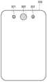
먼저, 도 1a는 일 실시예에 따른 촬상 장치(100)의 개략적인 구조를 도시하고 있다. 예를 들어, 촬상 장치(100)는 휴대전화, 태블릿 PC 또는 노트북 PC 등과 같은 모바일 장치일 수 있다. 도 1a를 참조하면, 촬상 장치(100)는 직경이 서로 다른 제 1 렌즈 소자(101), 제 2 렌즈 소자(102) 및 제 3 렌즈 소자(103)를 포함할 수 있다. 예를 들어, 제 1 렌즈 소자(101)는 가장 작은 제 1 직경을 가질 수 있고, 제 2 렌즈 소자(102)는 제 1 직경보다 큰 제 2 직경을 갖고, 제 3 렌즈 소자(103)는 제 2 직경보자 큰 제 3 직경을 가질 수 있다. 또한, 상기 제 1 내지 제 3 렌즈 소자(101, 102, 103)는 수평 방향을 따라 일렬로 배열될 수 있다. 예를 들어, 제 3 렌즈 소자(103)가 좌측에 배치되고 제 1 렌즈 소자(101)가 중심부에 배치되며 제 2 렌즈 소자(102)가 우측에 배치될 수 있다.First, FIG. 1A shows a schematic structure of an
도 1b는 도 1a에 도시된 촬상 장치(100)에서 렌즈 소자(101, 102, 103)들 및 촬상 영역(111, 112, 113)들의 배치 구조를 보이는 단면도이다. 도 1b를 참조하면, 각각의 렌즈 소자(101, 102, 103)에 대해 그에 대응하는 촬상 영역(111, 112, 113)이 배치될 수 있다. 예를 들어, 제 1 렌즈 소자(101)의 초점 평면에 제 1 촬상 영역(111)이 배치되며, 제 2 렌즈 소자(102)의 초점 평면에 제 2 촬상 영역(112)이 배치되고, 제 3 렌즈 소자(103)의 초점 평면에 제 3 촬상 영역(113)이 배치될 수 있다. 따라서, 제 1 내지 제 3 촬상 영역(111, 112, 113)들은 그에 각각 대응하는 제 1 내지 제 3 렌즈 소자(101, 102, 103)들에 의해 각각 포커싱되는 빛을 이용하여 각각 영상을 형성할 수 있다. 이러한 제 1 내지 제 3 촬상 영역(111, 112, 113)들은 물리적으로 분리된 별개의 이미지 센서를 각각 포함할 수 있다. 이미지 센서는, 예를 들어, CCD(charge-coupled device) 또는 CMOS(complementary metal oxide semiconductor) 이미지 센서일 수 있다.FIG. 1B is a cross-sectional view showing an arrangement structure of the
제 1 내지 제 3 렌즈 소자(101, 102, 103)의 초점거리는 서로 동일할 수도 있지만, 촬상 장치(100)의 내부 공간이 허용하는 범위 내에서 필요에 따라 제 1 내지 제 3 렌즈 소자(101, 102, 103)의 초점거리가 서로 조금씩 달라질 수도 있다. 그러나, 촬상 장치(100)의 내부 공간이 협소하여 초점거리의 차이가 크지 않기 때문에, 제 1 내지 제 3 렌즈 소자(101, 102, 103)의 밝기는 주로 직경에 의해 결정된다. 예를 들어, 직경이 가장 작은 제 1 렌즈 소자(101)의 F 수는 2.2이고, 제 2 렌즈 소자(102)의 F 수는 1.5이며, 직경이 가장 큰 제 3 렌즈 소자(103)의 F 수는 1.0일 수 있다. 일반적으로, 렌즈 소자에 의해 포커싱되는 광스폿의 이론적인 크기는 렌즈 소자의 F 수에 의해 결정된다. 구체적으로, 렌즈 소자의 F 수가 감소함에 따라, 즉 렌즈 소자의 밝기가 밝을수록 광스폿의 크기가 작아지게 된다. 따라서, F 수가 가장 작은 제 3 렌즈 소자(103)에 의해 형성되는 광스폿의 크기가 가장 작을 수 있다.The focal lengths of the first to
도 1c는 도 1a에 도시된 촬상 장치(100)의 촬상 영역(111, 112, 113)들의 크기 및 화소 피치를 예시적으로 도시하고 있다. 도 1c를 참조하면, 제 1 내지 제 3 촬상 영역(111, 112, 113)들의 크기가 서로 다를 수 있다. 예를 들어, 제 1 및 제 2 촬상 영역(111, 112)은 동일한 제 1 크기를 갖고, 제 3 촬상 영역(113)은 제 1 크기보다 작은 제 2 크기를 가질 수 있다. 앞서 설명한 바와 같이, 제 1 내지 제 3 렌즈 소자(101, 102, 103)들의 초점거리가 동일하거나 또는 초점거리의 차이가 크지 않기 때문에, 화각은 촬상 영역(111, 112, 113)들의 크기에 의해 결정된다. 예를 들어, 제 1 및 제 2 촬상 영역(111, 112)을 통해 취득된 영상은 동일한 제 1 화각을 가지며, 제 3 촬상 영역(113)을 통해 취득된 영상은 제 1 화각보다 좁은 제 2 화각을 가질 수 있다. 이러한 점에서, 제 3 촬상 영역(113)은 제 1 및 제 2 촬상 영역(111, 112)과 비교할 때 상대적으로 망원 줌의 역할을 할 수 있다. 즉, 제 1 및 제 2 촬상 영역(111, 112)은 상대적으로 광각인 제 1 줌을 제공하고, 제 3 촬상 영역(113)은 상대적으로 망원인 제 2 줌을 제공할 수 있다. 따라서, 본 실시예에 따른 촬상 장치(100)는 광각의 제 1 줌과 망원의 제 2 줌을 갖는 줌 기능을 제공할 수 있다.FIG. 1C exemplarily illustrates the size and pixel pitch of the
또한, 도 1c에는 각각의 촬상 영역(111, 112, 113)들 내에서 동일한 면적을 갖는 일부 영역을 동일한 비율로 확대하여 보인 화소(121, 122, 123)들이 각각 도시되어 있다. 도 1c에 도시된 바와 같이, 촬상 영역(111, 112, 113)들은 서로 다른 화소 피치를 가질 수 있다. 예를 들어, 제 1 촬상 영역(111)은 제 1 화소 피치를 갖고, 제 2 촬상 영역(112)은 제 1 화소 피치보다 작은 제 2 화소 피치를 가지며, 제 3 촬상 영역(113)은 제 2 화소 피치보다 작은 제 3 화소 피치를 가질 수 있다. 즉, 각각의 촬상 영역(111, 112, 113)에 대응하는 렌즈 소자(101, 102, 103)의 F 수(또는 직경)가 클수록 촬상 영역(111, 112, 113)의 화소 피치가 작아지고, 각각의 촬상 영역(111, 112, 113)에 대응하는 렌즈 소자(101, 102, 103)의 F 수(또는 직경)가 작을수록 촬상 영역(111, 112, 113)의 화소 피치가 커질 수 있다. 예를 들어, F 수가 가장 큰 제 1 렌즈 소자(101)에 대응하는 촬상 영역(111)의 화소 피치가 가장 크고, F 수가 가장 작은 제 3 렌즈 소자(103)에 대응하는 촬상 영역(113)의 화소 피치가 가장 작을 수 있다.Also, in FIG. 1C ,
일반적으로, 영상의 해상도는 광학계의 변조 전달 함수(modulation transfer function; MTF)와 화소의 주파수 응답 특성에 비례하며, 변조 전달 함수는 광학계의 F 수가 작아질수록 증가한다. 따라서, 광학계의 F 수가 작아지면 해상도를 향상시킬 수 있다. 그러나, 광스폿의 크기가 작아지더라도 화소 피치가 지나치게 크면 화소의 응답 특성이 저하되어 해상도가 향상되지 않는다. 따라서, 광스폿의 축소에 대응하여 화소 피치가 작아질 때 해상도가 향상될 수 있다.In general, the resolution of an image is proportional to a modulation transfer function (MTF) of an optical system and a frequency response characteristic of a pixel, and the modulation transfer function increases as the F number of the optical system decreases. Therefore, when the F number of the optical system becomes small, the resolution can be improved. However, even if the size of the light spot is reduced, if the pixel pitch is too large, the pixel response characteristic is deteriorated, so that the resolution is not improved. Accordingly, the resolution can be improved when the pixel pitch becomes smaller in response to the reduction of the light spot.
본 실시예에 따르면, F 수가 가장 작은 제 3 렌즈 소자(103)에 의해 형성되는 광스폿의 크기가 가장 작고, F 수가 가장 큰 제 1 렌즈 소자(101)에 의해 형성되는 광스폿의 크기가 가장 크다. 또한, F 수가 가장 작은 제 1 렌즈 소자(101)에 대응하는 촬상 영역(111)의 화소 피치가 가장 크고, F 수가 가장 큰 제 3 렌즈 소자(103)에 대응하는 촬상 영역(113)의 화소 피치가 가장 작다. 그 결과, 제 3 렌즈 소자(103)와 제 3 촬상 영역(113)에 의해 형성되는 영상이 가장 높은 해상도를 가지며, 제 1 렌즈 소자(101)와 제 1 촬상 영역(111)에 의해 형성되는 영상이 가장 낮은 해상도를 가질 수 있다. 앞서 설명한 바와 같이, 제 3 렌즈 소자(103)와 제 3 촬상 영역(113)은 망원 줌의 역할을 할 수 있으므로, 제 3 렌즈 소자(103)와 제 3 촬상 영역(113)에 의해 형성되는 영상의 해상도를 향상시킴으로써 화각이 좁은 영상의 화질 열화 문제를 개선할 수 있다. 따라서, 본 실시예에 따른 촬상 장치(100)는 가변 초점거리를 갖는 광학계를 사용하지 않으면서도, 광각 줌과 망원 줌 사이의 전환시에 화질의 열화가 발생하지 않은 줌 기능을 제공할 수 있다.According to this embodiment, the size of the light spot formed by the
한편, 제 1 및 제 2 촬상 영역(111, 112)의 크기가 동일하기 때문에, 제 1 및 제 2 촬상 영역(111, 112)을 통해 각각 취득된 제 1 및 제 2 영상은, 동일한 화각을 갖는 동시에, 제 1 및 제 2 렌즈 소자(101, 102)의 위치 차이로 인한 상이한 시차를 갖게 된다. 따라서, 본 실시예에 따른 촬상 장치(100)는 화각이 동일하고 시차가 다른 제 1 및 제 2 영상을 이용하여 깊이 정보를 추출하는 것이 가능하다. 즉, 제 1 렌즈 소자(101)와 제 1 촬상 영역(111) 및 제 2 렌즈 소자(102)와 제 2 촬상 영역(112)은 한 쌍의 스테레오 카메라(stereo camera)로 동작할 수 있다. 또한, 제 3 촬상 영역(113)을 통해 취득한 고해상도의 제 3 영상을 이용하여 보다 정밀한 깊이 정보를 추출할 수도 있다. 예를 들어, 제 1 및 제 2 영상의 중심부는 화각이 좁은 제 3 영상에 대응할 수 있으므로, 중심 화각에 대해서는 제 1 영상보다 해상도가 높은 제 2 영상의 중심부와 제 3 영상을 이용하여 깊이 정보를 추출하고, 주변 화각에 대해서는 제 1 영상의 주변부와 제 2 영상의 주변부를 이용하여 깊이 정보를 추출할 수도 있다.Meanwhile, since the sizes of the first and
또한, 제 2 영상은 제 1 영상과 화각이 동일하고 제 1 영상보다 해상도가 높기 때문에, 사용자에게 제 1 줌의 영상을 디스플레이 할 때, 촬상 장치(100)는 제 2 영상을 선택하여 디스플레이 할 수 있다. 그 대신에, 제 3 영상은 제 2 영상보다 해상도가 높고 화각이 좁기 때문에, 사용자에게 제 1 줌의 영상을 디스플레이 할 때, 촬상 장치(100)는 제 3 영상에 대응하는 제 2 영상의 중심부 영역만을 제 3 영상으로 대체하여 사용자에게 디스플레이 할 수도 있다. 또한, 촬상 소자(100)는 제 1 줌과 제 2 줌 사이의 구간에 대해서는 영상 신호 처리를 통해 디지털 줌의 방식으로 사용자에게 제공할 수 있다. 이때, 제 1 줌과 제 2 줌 사이에서 매끄러운 디지털 줌을 제공할 수 있도록 해상도가 높은 제 2 영상과 제 3 영상을 이용할 수 있다.Also, since the second image has the same angle of view as the first image and has a higher resolution than the first image, when displaying the image of the first zoom to the user, the
상술한 바와 같이, 본 실시예에 따른 촬상 장치(100)는 화각이 상이한 다수의 영상들을 동시에 얻을 수 있다. 따라서, 촬상 장치(100)의 두께를 증가시키기 않으면서 광학적 줌 기능을 달성할 수 있다. 또한, 좁은 화각의 영상에 대해서도 높은 해상도를 달성할 수 있다.As described above, the
도 1a 내지 도 1c에 도시된 실시예에서는, 촬상 장치(100)가 예시적으로 3개의 렌즈 소자(101, 102, 103)와 3개의 촬상 영역(101, 102, 103)들을 갖는 것으로 설명하였으나, 이는 단순한 예로서 본 실시예에는 이에 한정되지 않는다. 예를 들어, 2개의 렌즈 소자와 2개의 촬상 영역 또는 4개 이상의 렌즈 소자와 4개 이상의 촬상 영역들을 다양한 방식으로 배치하는 것이 가능하다. 또한, 렌즈 소자들의 직경, 촬상 영역들의 크기, 및 촬상 영역들의 화소 피치도 목적에 따라 다양하게 선택할 수 있다. 이하, 가능한 다양한 실시예들에 대해 예시적으로 설명하지만, 본 발명이 이하에서 예시된 실시예들에 제한되는 것은 아니다.In the embodiment shown in FIGS. 1A to 1C , the
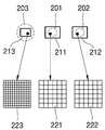
도 2a는 다른 실시예에 따른 촬상 장치(200)의 개략적인 구조를 보이며, 도 2b는 도 2a에 도시된 촬상 장치(200)에서 렌즈 소자(201, 202, 203)들 및 촬상 영역(211, 212, 213)들의 배치 구조를 보이고, 도 2c는 촬상 영역(211, 212, 213)들의 크기 및 화소 피치를 예시적으로 보인다.2A shows a schematic structure of an
도 2a를 참조하면, 본 실시예에 따른 촬상 장치(200)는 제 1 직경을 갖는 제 1 렌즈 소자(201), 제 1 직경을 갖는 제 2 렌즈 소자(202), 및 제 1 직경보다 큰 제 2 직경을 갖는 제 3 렌즈 소자(203)를 포함할 수 있다. 즉, 제 1 및 제 2 렌즈 소자(201, 202)는 동일한 직경을 갖고, 제 3 렌즈 소자(203)는 상기 제 1 및 제 2 렌즈 소자(201, 202)보다 큰 직경을 가질 수 있다. 따라서, 제 3 렌즈 소자(203)가 가장 작은 F 수를 가지므로, 제 3 렌즈 소자(203)에 의해 형성되는 광스폿의 크기가 가장 작다. 또한, 제 1 내지 제 3 렌즈 소자(201, 202, 203)는 수평 방향을 따라 일렬로 배열될 수 있다. 예를 들어, 제 3 렌즈 소자(203)가 좌측에 배치되고 제 1 렌즈 소자(201)가 중심부에 배치되며 제 2 렌즈 소자(202)가 우측에 배치될 수 있다.Referring to FIG. 2A , the
도 2b 및 도 2c를 참조하면, 제 1 내지 제 3 렌즈 소자(201, 202, 203)에 대해 그에 각각 대응하는 제 1 내지 제 3 촬상 영역(211, 212, 213)이 각각 배치될 수 있다. 이러한 제 1 내지 제 3 촬상 영역(211, 212, 213)들은 물리적으로 분리된 별개의 이미지 센서를 각각 포함할 수 있다. 제 1 내지 제 3 촬상 영역(211, 212, 213)들은 서로 다른 크기 및 서로 다른 화소 피치를 가질 수 있다. 예를 들어, 제 1 및 제 2 촬상 영역(211, 212)은 동일한 제 1 크기를 갖고, 제 3 촬상 영역(213)은 제 1 크기보다 작은 제 2 크기를 가질 수 있다. 따라서, 제 1 및 제 2 촬상 영역(211, 212)을 통해 취득된 영상은 동일한 제 1 화각을 가지며, 제 3 촬상 영역(213)을 통해 취득된 영상은 제 1 화각보다 좁은 제 2 화각을 가질 수 있다.Referring to FIGS. 2B and 2C , first to
또한, 도 2c에서 확대하여 보인 화소(221, 222, 223)들을 참조하면, 제 1 및 제 2 촬상 영역(211, 212)은 동일한 제 1 화소 피치를 갖고, 제 3 촬상 영역(213)은 제 1 화소 피치보다 작은 제 2 화소 피치를 가질 수 있다. 따라서 제 1 및 제 2 촬상 영역(211, 212)을 통해 취득된 영상은 제 3 촬상 영역(213)을 통해 취득된 영상보다 해상도가 낮다. 그러나, 예를 들어 슈퍼 레졸루션(super resolution)과 같은 해상도 향상 기법을 이용하여 제 1 및 제 2 촬상 영역(211, 212)을 통해 취득된 영상의 해상도를 향상시킬 수 있다. 예컨대, 제 1 및 제 2 촬상 영역(211, 212)을 통해 각각 취득된 2개의 영상을 합성하여 해상도가 향상된 하나의 영상을 생성하는 것이 가능하다. 이러한 슈퍼 레졸루션 기법을 이용하면, 제 1 화각과 제 2 화각 사이의 화각을 갖는 영상을 생성하는 디지털 줌 기능을 제공할 때, 매끄러운 영상 처리가 가능하다. 촬상 장치(200)의 그 외의 기능과 동작은 도 1a 내지 도 1c에서 설명한 것과 같을 수 있다.In addition, referring to the
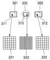
도 3a는 또 다른 실시예에 따른 촬상 장치(300)의 개략적인 구조를 보이며, 도 3b는 도 3a에 도시된 촬상 장치(300)에서 렌즈 소자(301, 302, 303)들 및 촬상 영역(311, 312, 313)들의 배치 구조를 보이고, 도 3c는 촬상 영역(311, 312, 313)들의 크기 및 화소 피치를 예시적으로 보인다.3A shows a schematic structure of an
도 3a를 참조하면, 본 실시예에 따른 촬상 장치(300)는 제 1 직경을 갖는 제 1 렌즈 소자(301), 제 1 직경을 갖는 제 2 렌즈 소자(302), 및 제 1 직경보다 큰 제 2 직경을 갖는 제 3 렌즈 소자(303)를 포함할 수 있다. 즉, 제 1 및 제 2 렌즈 소자(301, 302)는 동일한 직경을 갖고, 제 3 렌즈 소자(303)는 상기 제 1 및 제 2 렌즈 소자(301, 302)보다 큰 직경을 가질 수 있다. 따라서, 제 3 렌즈 소자(303)가 가장 작은 F 수를 가지므로, 제 3 렌즈 소자(303)에 의해 형성되는 광스폿의 크기가 가장 작다.Referring to FIG. 3A , the
도 3b 및 도 3c를 참조하면, 제 1 내지 제 3 렌즈 소자(301, 302, 303)에 대해 그에 각각 대응하는 제 1 내지 제 3 촬상 영역(311, 312, 313)이 각각 배치될 수 있다. 이러한 제 1 내지 제 3 촬상 영역(311, 312, 313)들은 서로 다른 크기 및 서로 다른 화소 피치를 가질 수 있다. 예를 들어, 제 1 및 제 2 촬상 영역(311, 312)은 동일한 제 1 크기를 갖고, 제 3 촬상 영역(313)은 제 1 크기보다 작은 제 2 크기를 가질 수 있다. 따라서, 제 1 및 제 2 촬상 영역(311, 312)을 통해 취득된 영상은 동일한 제 1 화각을 가지며, 제 3 촬상 영역(313)을 통해 취득된 영상은 제 1 화각보다 좁은 제 2 화각을 가질 수 있다. 또한, 도 3c에서 확대하여 보인 화소(321, 322, 323)들을 참조하면, 제 1 및 제 2 촬상 영역(311, 312)은 동일한 제 1 화소 피치를 갖고, 제 3 촬상 영역(313)은 제 1 화소 피치보다 작은 제 2 화소 피치를 가질 수 있다. 따라서 제 3 촬상 영역(313)을 통해 취득된 영상은 제 1 및 제 2 촬상 영역(311, 312)을 통해 취득된 영상보다 해상도가 높다.3B and 3C , first to
도 3a에 도시된 촬상 장치(300)는 도 2a에 도시된 촬상 장치(200)와 유사한 구조를 가지며, 단지 렌즈 소자(301, 302, 303)들 및 촬상 영역(311, 312, 313)들의 위치에 차이가 있다. 예를 들어, 제 3 렌즈 소자(303)가 중심에 배치되고, 그 양측에 제 1 렌즈 소자(301)와 제 2 렌즈 소자(302)가 배치될 수 있다. 따라서, 도 2a에 도시된 실시예에 비하여, 제 1 렌즈 소자(301)와 제 2 렌즈 소자(302) 사이의 간격이 멀어지기 때문에, 시차가 커져서 깊이 정보의 해상도 및 정확도가 향상될 수 있다.The
도 4a는 또 다른 실시예에 따른 촬상 장치(400)의 개략적인 구조를 보이며, 도 4b는 도 4a에 도시된 촬상 장치(400)에서 렌즈 소자(401, 402, 403)들 및 촬상 영역(411, 412, 413)들의 배치 구조를 보이고, 도 4c는 촬상 영역(411, 412, 413)들의 크기를 예시적으로 보인다.FIG. 4A shows a schematic structure of an
도 4a를 참조하면, 본 실시예에 따른 촬상 장치(400)는 제 1 직경을 갖는 제 1 렌즈 소자(401), 제 1 직경을 갖는 제 2 렌즈 소자(402), 및 제 1 직경보다 큰 제 2 직경을 갖는 제 3 렌즈 소자(403)를 포함할 수 있다. 즉, 제 1 및 제 2 렌즈 소자(401, 402)는 동일한 직경을 갖고, 제 3 렌즈 소자(403)는 상기 제 1 및 제 2 렌즈 소자(301, 302)보다 큰 직경을 가질 수 있다. 따라서, 제 3 렌즈 소자(403)가 가장 작은 F 수를 가지므로, 제 3 렌즈 소자(403)에 의해 형성되는 광스폿의 크기가 가장 작다.Referring to FIG. 4A , the
도 4b 및 도 4c를 참조하면, 제 1 내지 제 3 렌즈 소자(401, 402, 403)에 대해 그에 각각 대응하는 제 1 내지 제 3 촬상 영역(411, 412, 413)들이 각각 배치될 수 있다. 여기서, 상기 제 1 내지 제 3 촬상 영역(411, 412, 413)들은 하나의 이미지 센서(410) 내에서 논리적으로 분할된 영역들일 수 있다. 예를 들어, 도 4c에 도시된 바와 같이, 하나의 이미지 센서(410) 내에서, 제 1 촬상 영역(411)은 제 1 렌즈 소자(401)에 의해 포커싱되는 빛을 감지하도록 분할된 영역이고, 제 2 촬상 영역(412)은 제 2 렌즈 소자(402)에 의해 포커싱되는 빛을 감지하도록 분할된 영역이며, 제 3 촬상 영역(413)은 제 3 렌즈 소자 (403)에 의해 포커싱되는 빛을 감지하도록 분할된 영역이다. 이 경우, 제 1 내지 제 3 촬상 영역(411, 412, 413)들은 모두 동일한 화소 피치를 가질 수 있다.4B and 4C , first to
이러한 제 1 내지 제 3 촬상 영역(411, 412, 413)들은 서로 다른 크기를 가질 수 있다. 예를 들어, 제 1 및 제 2 촬상 영역(411, 412)은 동일한 제 1 크기를 갖고, 제 3 촬상 영역(413)은 제 1 크기보다 작은 제 2 크기를 가질 수 있다. 이를 위하여, 촬상 장치(400)의 도시되지 않은 영상 처리부가 이미지 센서(410) 내의 화소들을 미리 정해진 좌표에 따라 제 1 내지 제 3 촬상 영역(411, 412, 413) 및 그외의 더미 영역으로 분리할 수 있다. 그리고, 영상 처리부는 제 1 촬상 영역(411)에서 발생하는 신호만을 이용하여 제 1 영상을 생성하고, 제 2 촬상 영역(412)에서 발생하는 신호만을 이용하여 제 2 영상을 생성하며, 제 3 촬상 영역(413)에서 발생하는 신호만을 이용하여 제 3 영상을 생성하고, 그외의 더미 영역에서 발생하는 신호를 무시할 수 있다.The first to
본 실시예에 따르면, 제 1 내지 제 3 촬상 영역(411, 412, 413)에 대해 각각 별개의 이미지 센서를 사용하지 않고, 하나의 공통된 이미지 센서(410)를 사용하기 때문에, 조립 공정이 용이하고 제조 비용을 줄일 수 있다. 도 4a 내지 도 4c에서 설명한 단일 이미지 센서(410)의 구조는 다른 실시예들에도 적용할 수 있다.According to this embodiment, since separate image sensors are not used for the first to
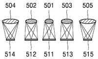
도 5a는 또 다른 실시예에 따른 촬상 장치(500)의 개략적인 구조를 보이며, 도 5b는 도 5a에 도시된 촬상 장치(500)에서 렌즈 소자(501, 502, 503, 504, 505)들 및 촬상 영역(511, 512, 513, 514, 515)들의 배치 구조를 보이고, 도 5c는 촬상 영역(511, 512, 513, 514, 515)들의 크기 및 화소 피치를 예시적으로 보인다.5A shows a schematic structure of an
도 5a를 참조하면, 본 실시예에 따른 촬상 장치(500)는 제 1 직경을 갖는 제 1 렌즈 소자(501), 제 1 직경보다 큰 제 2 직경을 갖는 제 2 렌즈 소자(502), 제 2 직경을 갖는 제 3 렌즈 소자(503), 제 2 직경보다 큰 제 3 직경을 갖는 제 4 렌즈 소자(504), 및 제 3 직경을 갖는 제 5 렌즈 소자(505)를 포함할 수 있다. 즉, 제 1 렌즈 소자(501)의 직경이 가장 작다. 그리고, 제 2 및 제 3 렌즈 소자(502, 503)의 직경이 서로 동일하며 제 1 렌즈 소자(501)의 직경보다 크고, 제 4 및 제 5 렌즈 소자(504, 505)의 직경이 가장 크다. 따라서, 제 1 렌즈 소자(501)가 가장 큰 F 수를 가지며, 제 4 및 제 5 렌즈 소자(504, 505)가 가장 작은 F 수를 갖는다. 이러한 제 1 내지 제 5 렌즈 소자(501, 502, 503, 504, 505)들은 수평 방향을 따라 일렬로 배열될 수 있다. 예를 들어, 제 1 렌즈 소자(501)가 가운데 배치되고, 제 2 및 제 3 렌즈 소자(502, 503)가 제 1 렌즈 소자(501)의 양측에 배치되며, 제 4 및 제 5 렌즈 소자(504, 505)가 각각 가장 좌측과 가장 우측에 배치될 수 있다.Referring to FIG. 5A , the
도 5b 및 도 5c를 참조하면, 제 1 내지 제 5 렌즈 소자(501, 502, 503, 504, 505)에 대해 그에 각각 대응하는 제 1 내지 제 5 촬상 영역(511, 512, 513, 514, 515)이 각각 배치될 수 있다. 이러한 제 1 내지 제 5 촬상 영역(511, 512, 513, 514, 515)들은 서로 다른 크기 및 서로 다른 화소 피치를 가질 수 있다. 예를 들어, 제 1 내지 제 3 촬상 영역(511, 512, 513)들은 동일한 제 1 크기를 갖고, 제 4 및 제 5 촬상 영역(514, 515)들은 제 1 크기보다 작은 제 2 크기를 가질 수 있다. 따라서, 제 1 내지 제 3 촬상 영역(511, 512, 513)들을 통해 취득된 영상은 동일한 제 1 화각을 가지며, 제 4 및 제 5 촬상 영역(514, 515)들을 통해 취득된 영상은 제 1 화각보다 좁은 제 2 화각을 가질 수 있다.5B and 5C, for the first to
또한, 도 5c에서 확대하여 보인 화소(521, 522, 523, 524, 525)들을 참조하면, 제 1 촬상 영역(511)은 제 1 화소 피치를 갖고, 제 2 및 제 3 촬상 영역(512, 513)은 제 1 화소 피치보다 작은 제 2 화소 피치를 가지며, 제 4 및 제 5 촬상 영역(514, 515)은 제 2 화소 피치보다 작은 제 3 화소 피치를 가질 수 있다. 따라서 제 2 및 제 3 촬상 영역(512, 513)을 통해 취득된 영상은 제 1 촬상 영역(511)을 통해 취득된 영상보다 해상도가 높고, 제 4 및 제 5 촬상 영역(514, 515)을 통해 취득된 영상은 제 2 및 제 3 촬상 영역(512, 513)을 통해 취득된 영상보다 해상도가 높다.Also, referring to the
이러한 구조에서, 제 1 렌즈 소자(501)와 제 1 촬상 영역(511)으로 제 1 화각의 영상을 제공하고, 제 2 및 제 3 렌즈 소자(502, 503)와 제 2 및 제 3 촬상 영역(512, 513)으로 제 1 화각의 영상을 제공하며, 제 4 및 제 5 렌즈 소자(504, 505)와 제 4 및 제 5 촬상 영역(514, 515)으로 제 2 화각의 영상을 제공할 수 있다. 또한, 제 2 및 제 3 렌즈 소자(502, 503)와 제 2 및 제 3 촬상 영역(512, 513)을 통해 각각 취득된 2개의 영상을 이용하여 제 1 화각의 영상에 대한 깊이 정보의 추출이 가능하고, 제 4 및 제 5 렌즈 소자(504, 505)와 제 4 및 제 5 촬상 영역(514, 515)을 통해 각각 취득된 2개의 영상을 이용하여 제 2 화각의 영상에 대한 깊이 정보의 추출이 가능하다.In this structure, an image of a first angle of view is provided to the
일반적으로, 거리가 멀어질수록 깊이 정보의 정확도가 저하되므로, 망원 줌 기능을 제공하는 제 4 및 제 5 렌즈 소자(504, 505) 사이의 간격이 가장 크도록 제 4 및 제 5 렌즈 소자(504, 505)를 가장 바깥쪽에 배치할 수 있다. 그러면, 제 4 및 제 5 렌즈 소자(504, 505)를 통해 취득한 2개의 영상들 사이의 시차가 커져서 깊이 정보의 정확도 저하를 보상할 수 있다.In general, since the accuracy of depth information decreases as the distance increases, the fourth and
또한, 제 1 촬상 영역(511)에서 취득한 영상의 화각과 제 2 및 제 3 촬상 영역(512, 513)에서 취득한 영상의 화각이 동일하기 때문에, 제 2 및 제 3 촬상 영역(512, 513)을 통해 추출한 깊이 정보를 제 1 촬상 영역(511)에서 취득한 영상에 적용하는 것이 가능하다. 또는, 제 1 내지 제 3 촬상 영역(511, 512, 513)에서 취득한 3개의 영상들을 모두 이용하여 깊이 정보를 추출할 수도 있다. 또는, 제 1 촬상 영역(511)에서 취득한 영상과 제 2 촬상 영역(512)에서 취득한 영상을 이용하여 깊이 정보를 추출하는 동시에, 제 2 촬상 영역(512)에서 취득한 영상과 제 3 촬상 영역(513)에서 취득한 영상을 이용하여 깊이 정보를 추출할 수도 있다.In addition, since the angle of view of the image acquired in the
도 5a 내지 도 5c에 도시된 촬상 장치(500)에서, 필요에 따라 일부 구성을 생략하거나 변형하는 것도 가능하다. 예컨대, 제 2 및 제 3 렌즈 소자(502, 503)들과 제 2 및 제 3 촬상 영역(512, 513)들을 제거하거나, 또는 제 4 및 제 5 렌즈 소자(504, 505)들과 제 4 및 제 5 촬상 영역(514, 515)들을 제거할 수도 있다. 이 경우, 촬상 장치(500)는 대칭적으로 배치된 3개의 렌즈 소자와 3개의 촬상 영역을 갖게 될 수 있다. 이때, 깊이 정보 추출의 편의상 3개의 촬상 영역의 크기를 동일하게 선택할 수도 있다. 또한, 제 1 내지 제 3 촬상 영역(511, 512, 513)들의 화소 피치를 동일하게 선택하고, 제 1 내지 제 3 렌즈 소자(501, 502, 503)들의 직경을 동일하게 선택할 수도 있다. 그러면, 슈퍼 레졸루션과 같은 해상도 향상 기법을 이용하여 영상의 해상도를 향상시킬 수 있으며, 깊이 정보의 정확도를 향상시킬 수도 있다.In the
도 6a는 또 다른 실시예에 따른 촬상 장치(600)의 개략적인 구조를 보이며, 도 6b는 도 6a에 도시된 촬상 장치(600)에서 촬상 영역(611, 612, 613, 614, 615, 616, 617, 618, 619)들의 한 예를 예시적으로 보이고, 도 6c는 촬상 영역(611, 612, 613, 614, 615, 616, 617, 618, 619)들의 다른 예를 보인다.6A shows a schematic structure of an
도 6a를 참조하면, 본 실시예에 따른 촬상 장치(600)는 제 1 직경을 갖는 제 1 렌즈 소자(601), 제 1 직경보다 큰 제 2 직경을 갖는 제 2 내지 제 5 렌즈 소자(602, 603, 604, 605), 및 제 2 직경보다 큰 제 3 직경을 갖는 제 6 내지 제 9 렌즈 소자(606, 607, 608, 609)들 포함할 수 있다. 즉, 제 1 렌즈 소자(601)의 직경이 가장 작다. 그리고, 제 2 내지 제 5 렌즈 소자(602, 603, 604, 605)의 직경이 서로 동일하며 제 1 렌즈 소자(601)의 직경보다 크고, 제 6 내지 제 9 렌즈 소자(606, 607, 608, 609)의 직경이 가장 크다. 따라서, 제 1 렌즈 소자(601)가 가장 큰 F 수를 가지며, 제 6 내지 제 9 렌즈 소자(606, 607, 608, 609)가 가장 작은 F 수를 갖는다.Referring to FIG. 6A , the
이러한 제 1 내지 제 9 렌즈 소자(601, 602, 603, 604, 605, 606, 607, 608, 609)들은 수평 방향과 수직 방향을 따라 2차원적으로 배열될 수 있다. 예를 들어, 제 1 렌즈 소자(601)에 대해 수직 방향과 수평 방향으로 제 2 내지 제 5 렌즈 소자(602, 603, 604, 605)들이 각각 배치되고, 제 1 렌즈 소자(601)에 대해 45도 대각선 방향으로 제 6 내지 제 9 렌즈 소자(606, 607, 608, 609)들이 각각 배치될 수 있다. 바꾸어 말하자면, 사각형 모양의 4개의 꼭지점 위치에 제 6 내지 제 9 렌즈 소자(606, 607, 608, 609)들이 각각 배치되고, 상기 사각형 모양의 4개의 변의 중심에 제 2 내지 제 5 렌즈 소자(602, 603, 604, 605)들이 각각 배치되며, 상기 사각형 모양의 중앙에 제 1 렌즈 소자(601)가 배치될 수 있다.The first to
또한, 도 6b를 참조하면, 제 1 내지 제 9 렌즈 소자(601, 602, 603, 604, 605, 606, 607, 608, 609)들에 대해 그에 각각 대응하는 제 1 내지 제 9 촬상 영역(611, 612, 613, 614, 615, 616, 617, 618, 619)들이 각각 배치될 수 있다. 이러한 제 1 내지 제 9 촬상 영역(611, 612, 613, 614, 615, 616, 617, 618, 619)들은 서로 다른 크기 및 서로 다른 화소 피치를 가질 수 있다. 예를 들어, 제 1 내지 제 5 촬상 영역(611, 612, 613, 614, 615)들은 동일한 제 1 크기를 갖고, 제 6 및 제 9 촬상 영역(616, 617, 618, 619)들은 제 1 크기보다 작은 제 2 크기를 가질 수 있다. 따라서, 제 1 내지 제 5 촬상 영역(611, 612, 613, 614, 615)들을 통해 취득된 영상은 동일한 제 1 화각을 가지며, 제 6 및 제 9 촬상 영역(616, 617, 618, 619)들을 통해 취득된 영상은 제 1 화각보다 좁은 제 2 화각을 가질 수 있다. 도시되지는 않았지만, 제 1 내지 제 5 촬상 영역(611, 612, 613, 614, 615)들은 제 1 화소 피치를 갖고, 제 6 및 제 9 촬상 영역(616, 617, 618, 619)들 제 1 화소 피치보다 작은 제 2 화소 피치를 가질 수 있다.Also, referring to FIG. 6B , first to
도 6b에는 제 1 내지 제 9 촬상 영역(611, 612, 613, 614, 615, 616, 617, 618, 619)들이 각각 별개의 이미지 센서를 포함하는 예를 보이고 있지만, 도 6c에 도시된 바와 같이 제 1 내지 제 9 촬상 영역(611, 612, 613, 614, 615, 616, 617, 618, 619)들은 하나의 이미지 센서(610) 내에서 논리적으로 분할된 영역들일 수 있다. 이 경우에도, 제 1 내지 제 5 촬상 영역(611, 612, 613, 614, 615)들은 동일한 제 1 크기를 갖고, 제 6 및 제 9 촬상 영역(616, 617, 618, 619)들은 제 1 크기보다 작은 제 2 크기를 가질 수 있다. 이 경우, 제 1 내지 제 9 촬상 영역(611, 612, 613, 614, 615, 616, 617, 618, 619)들은 모두 동일한 화소 피치를 가질 수 있다.6B shows an example in which the first to
이러한 구조에서, 제 2 내지 제 5 렌즈 소자(602, 603, 604, 605)들의 쌍 및 제 6 내지 제 9 렌즈 소자(606, 607, 608, 609)들의 쌍이 좌우 시차뿐만 아니라 상하 시차도 갖기 때문에, 수평 방향으로의 깊이 정보뿐만 아니라 수직 방향으로의 깊이 정보도 추출하는 것이 가능하다. 여기서, 제 6 내지 제 9 렌즈 소자(606, 607, 608, 609)들을 가장 바깥쪽에 배치함으로써, 망원 줌 기능을 제공하는 제 6 내지 제 9 렌즈 소자(606, 607, 608, 609)들 사이의 간격이 가장 크도록 할 수 있다. 또한, 제 1 내지 제 5 촬상 영역(611, 612, 613, 614, 615)들을 통해 취득한 5개의 제 1 화각의 영상에 대해 슈퍼 레졸류션 기법을 적용하여 해상도를 향상시킬 수 있으며, 제 6 및 제 9 촬상 영역(616, 617, 618, 619)들 통해 취득한 4개의 제 2 화각의 영상에 대해 슈퍼 레졸류션 기법을 적용하여 해상도를 향상시킬 수 있다. 또한, 이러한 슈퍼 레졸루션 기법을 이용하면, 제 1 화각과 제 2 화각 사이의 화각을 갖는 영상을 생성하는 디지털 줌 기능을 제공할 때, 매끄러운 영상 처리가 가능하다.In this structure, since the pair of second to
도 7은 또 다른 실시예에 따른 촬상 장치(700)의 개략적인 구조를 도시하고 있다. 도 7을 참조하면, 본 실시예에 따른 촬상 장치(700)는 제 1 직경을 갖는 제 1 내지 제 3 렌즈 소자(701, 702, 703), 및 제 1 직경보다 큰 제 2 직경을 갖는 제 4 및 제 5 렌즈 소자(704, 705)를 포함할 수 있다. 따라서, 제 1 내지 제 3 렌즈 소자(701, 702, 703)의 F 수가 서로 동일하고, 제 4 및 제 5 렌즈 소자(704, 705)의 F 수가 서로 동일하다. 그리고, 제 4 및 제 5 렌즈 소자(704, 705)의 F 수는 제 1 내지 제 3 렌즈 소자(701, 702, 703)의 F 수보다 작다. 비록 도시되지는 않았지만, 앞서 설명한 실시예와 마찬가지로, 제 1 내지 제 3 렌즈 소자(701, 702, 703)에 각각 대응하는 촬상 영역의 크기는 제 4 및 제 5 렌즈 소자(704, 705)에 각각 대응하는 촬상 영역의 크기보다 클 수 있다.7 shows a schematic structure of an
본 실시예에 따르면, 제 1 내지 제 3 렌즈 소자(701, 702, 703)들은 수평 방향을 따라 일렬로 배열될 수 있으며, 제 4 및 제 5 렌즈 소자(704, 705)들은 수직 방향을 따라 일렬로 배열될 수 있다. 예를 들어, 제 4 렌즈 소자(704)는 제 1 내지 제 3 렌즈 소자(701, 702, 703)들의 하부에 배치되고, 제 5 렌즈 소자(705)는 제 1 내지 제 3 렌즈 소자(701, 702, 703)들의 상부에 배치될 수 있다.According to the present embodiment, the first to
이러한 구조에서, 제 1 내지 제 3 렌즈 소자(701, 702, 703)들은 수평 방향의 시차를 갖기 때문에, 제 1 내지 제 3 렌즈 소자(701, 702, 703)들을 통해 취득한 3개의 영상을 이용하여 수평 방향으로의 깊이 정보를 추출할 수 있다. 또한, 제 4 및 제 5 렌즈 소자(704, 705)들은 수직 방향의 시차를 갖기 때문에, 제 4 및 제 5 렌즈 소자(704, 705)들을 통해 취득한 2개의 영상을 이용하여 수직 방향으로의 깊이 정보를 추출할 수 있다.In this structure, since the first to
또한, 제 1 내지 제 3 렌즈 소자(701, 702, 703)들을 통해 제 1 화각의 영상을 취득할 수 있으며, 제 4 및 제 5 렌즈 소자(704, 705)들을 통해 제 1 화각보다 좁은 제 2 화각의 영상을 취득할 수 있다. 여기서, 제 1 내지 제 3 렌즈 소자(701, 702, 703)들을 통해 취득한 3개의 제 1 화각의 영상에 대해 슈퍼 레졸류션 기법을 적용하여 해상도를 향상시킬 수 있으며, 제 4 및 제 5 렌즈 소자(704, 705)들을 통해 취득한 2개의 제 2 화각의 영상에 대해 슈퍼 레졸류션 기법을 적용하여 해상도를 향상시킬 수 있다. 이러한 슈퍼 레졸루션 기법을 이용하면, 제 1 화각과 제 2 화각 사이의 화각을 갖는 영상을 생성하는 디지털 줌 기능을 제공할 때, 매끄러운 영상 처리가 가능하다.In addition, an image of a first angle of view may be acquired through the first to
지금까지, 본 발명의 이해를 돕기 위하여 직경이 상이한 렌즈 소자들을 구비하는 촬상 장치에 대한 예시적인 실시예가 설명되고 첨부된 도면에 도시되었다. 그러나, 이러한 실시예는 단지 본 발명을 예시하기 위한 것이고 이를 제한하지 않는다는 점이 이해되어야 할 것이다. 그리고 본 발명은 도시되고 설명된 설명에 국한되지 않는다는 점이 이해되어야 할 것이다. 이는 다양한 다른 변형이 본 기술분야에서 통상의 지식을 가진 자에게 일어날 수 있기 때문이다.Up to now, exemplary embodiments of an imaging device having lens elements having different diameters have been described and shown in the accompanying drawings in order to facilitate understanding of the present invention. However, it should be understood that these examples are merely illustrative of the present invention and not limiting thereof. And it is to be understood that the present invention is not limited to the description shown and described. This is because various other modifications may occur to those skilled in the art.
100, 200, 300, 400, 500, 600, 700.....촬상 장치
101, 102, 103, 201, 202, 203, 301, 302, 303, 401, 402, 403, 501, 502, 503, 504, 505, 601, 602, 603, 604, 605, 606, 607, 609, 701, 702, 703, 704, 705.....렌즈 소자
111, 112, 113, 211, 212, 213, 311, 312, 313, 411, 412, 413, 511, 512, 513, 514, 515, 611, 612, 613, 614, 615, 616, 617, 619, 711, 712, 713, 714, 715.....촬상 영역100, 200, 300, 400, 500, 600, 700.....Image pickup device
101, 102, 103, 201, 202, 203, 301, 302, 303, 401, 402, 403, 501, 502, 503, 504, 505, 601, 602, 603, 604, 605, 606, 607, 609, 701, 702, 703, 704, 705.....Lens element
111, 112, 113, 211, 212, 213, 311, 312, 313, 411, 412, 413, 511, 512, 513, 514, 515, 611, 612, 613, 614, 615, 616, 617, 619, 711, 712, 713, 714, 715....Image area
Claims (24)
Translated fromKorean제 1 직경보다 큰 제 2 직경을 갖는 제 2 렌즈 소자;
제 1 렌즈 소자에 대응하여 배치된 것으로, 제 1 크기를 갖는 제 1 촬상 영역; 및
제 2 렌즈 소자에 대응하여 배치된 것으로, 제 1 크기보다 작은 제 2 크기를 갖는 제 2 촬상 영역;을 포함하고,
상기 제 1 렌즈 소자와 상기 제 1 촬상 영역은 제 1 화각을 제공하도록 구성되며, 상기 제 2 렌즈 소자와 상기 제 2 촬상 영역은 제 1 화각보다 좁은 제 2 화각을 제공하도록 구성되는 촬상 장치.a first lens element having a first diameter;
a second lens element having a second diameter greater than the first diameter;
a first imaging area disposed to correspond to the first lens element and having a first size; and
a second imaging area disposed to correspond to the second lens element and having a second size smaller than the first size; and
The first lens element and the first imaging area are configured to provide a first angle of view, and the second lens element and the second imaging area are configured to provide a second angle of view that is narrower than the first angle of view.
상기 제 1 촬상 영역 및 제 2 촬상 영역은 각각 물리적으로 분리된 별개의 이미지 센서를 포함하는 촬상 장치.The method of claim 1,
and the first imaging region and the second imaging region each include separate image sensors physically separated from each other.
상기 제 1 촬상 영역은 제 1 화소 피치를 가지며, 상기 제 2 촬상 영역은 제 1 화소 피치보다 작은 제 2 화소 피치를 갖는 촬상 장치.3. The method of claim 2,
The first imaging area has a first pixel pitch, and the second imaging area has a second pixel pitch smaller than the first pixel pitch.
상기 제 1 촬상 영역 및 제 2 촬상 영역은 하나의 이미지 센서 내에서 논리적으로 분할된 영역들인 촬상 장치.The method of claim 1,
The first imaging region and the second imaging region are regions that are logically divided within one image sensor.
상기 제 1 렌즈 소자는 상기 제 1 촬상 영역 상에서 제 1 크기의 광스폿을 형성하도록 구성되며, 상기 제 2 렌즈 소자는 상기 제 2 촬상 영역 상에서 제 1 크기보다 작은 제 2 크기의 광스폿을 형성하도록 구성된 촬상 장치.The method of claim 1,
the first lens element is configured to form a light spot of a first size on the first imaging area, and the second lens element is configured to form a light spot of a second size smaller than the first size on the second imaging area configured imaging device.
상기 제 1 렌즈 소자와 상기 제 1 촬상 영역을 이용하여 취득한 제 1 영상 및 상기 제 2 렌즈 소자와 상기 제 2 촬상 영역을 이용하여 취득한 제 2 영상으로부터 깊이 정보를 추출하도록 구성된 촬상 장치.The method of claim 1,
and extracting depth information from a first image acquired using the first lens element and the first imaging region and a second image acquired using the second lens element and the second imaging region.
제 1 직경보다 크고 제 2 직경보다 작은 제 3 직경을 갖는 제 3 렌즈 소자 및 상기 제 3 렌즈 소자에 대응하여 배치된 것으로 제 1 크기를 갖는 제 3 촬상 영역을 포함하며,
상기 제 1 촬상 영역을 제 1 화소 피치를 갖고, 상기 제 2 촬상 영역은 제 1 화소 피치보다 작은 제 2 화소 피치를 가지며, 상기 제 3 촬상 영역은 제 1 화소 피치보다 작으며 제 2 화소 피치보다 큰 제 3 화소 피치를 갖는 촬상 장치.The method of claim 1,
a third lens element having a third diameter greater than the first diameter and smaller than the second diameter; and a third imaging region disposed corresponding to the third lens element and having a first size;
the first imaging area has a first pixel pitch, the second imaging area has a second pixel pitch smaller than the first pixel pitch, and the third imaging area is smaller than the first pixel pitch and smaller than the second pixel pitch An imaging device having a large third pixel pitch.
제 1 직경을 갖는 제 3 렌즈 소자 및 상기 제 3 렌즈 소자에 대응하여 배치된 것으로 제 1 크기를 갖는 제 3 촬상 영역을 포함하며,
상기 제 1 및 제 3 촬상 영역은 제 1 화소 피치를 갖고, 상기 제 2 촬상 영역은 제 1 화소 피치보다 작은 제 2 화소 피치를 갖는 촬상 장치.The method of claim 1,
a third lens element having a first diameter and a third imaging area having a first size disposed corresponding to the third lens element,
The first and third imaging regions have a first pixel pitch, and the second imaging region has a second pixel pitch smaller than the first pixel pitch.
상기 제 2 렌즈 소자와 제 3 렌즈 소자 사이에 상기 제 1 렌즈 소자가 배치되고, 상기 제 2 촬상 영역과 제 3 촬상 영역 사이에 상기 제 1 촬상 영역이 배치되는 촬상 장치.9. The method of claim 8,
and the first lens element is disposed between the second lens element and the third lens element, and the first imaging area is disposed between the second imaging area and the third imaging area.
상기 제 1 렌즈 소자와 제 3 렌즈 소자 사이에 상기 제 2 렌즈 소자가 배치되고, 상기 제 1 촬상 영역과 제 3 촬상 영역 사이에 상기 제 2 촬상 영역이 배치되는 촬상 장치.9. The method of claim 8,
and wherein the second lens element is disposed between the first lens element and the third lens element, and the second imaging area is disposed between the first imaging area and the third imaging area.
상기 제 1 렌즈 소자와 상기 제 2 렌즈 소자는 상기 촬상 장치의 동일 면에 배치되어 있는 촬상 장치.The method of claim 1,
and the first lens element and the second lens element are disposed on the same surface of the image pickup device.
상기 제 1 렌즈 소자의 F 수는 상기 제 2 렌즈 소자의 F 수와 상이한 촬상 장치.The method of claim 1,
The F number of the first lens element is different from the F number of the second lens element.
상기 제 1 렌즈 소자의 F 수는 상기 제 2 렌즈 소자의 F 수 보다 1.5배 또는 2배 더 큰 촬상 장치.20. The method of claim 19,
The F number of the first lens element is 1.5 times or 2 times greater than the F number of the second lens element.
상기 제 1 렌즈 소자와 상기 제 1 촬상 영역을 이용하여 취득한 제 1 영상의 제 1 해상도는 상기 제 2 렌즈 소자와 상기 제 2 촬상 영역을 이용하여 취득한 제 2 영상의 제 2 해상도보다 낮은 촬상 장치.The method of claim 1,
The first resolution of the first image acquired using the first lens element and the first imaging region is lower than the second resolution of the second image acquired using the second lens element and the second imaging region.
상기 촬상 장치는 상기 제 2 영상의 화각에 대응하는 상기 제 1 영상의 중심부를 상기 제 2 영상으로 대체하여 변형된 영상을 형성하도록 구성된 촬상 장치.22. The method of claim 21,
and the imaging device is configured to form a deformed image by replacing a center of the first image corresponding to the angle of view of the second image with the second image.
상기 촬상 장치는 상기 제 1 영상의 주변부를 이용하여 주변 화각에 대한 깊이 정보를 추출하고 상기 제 2 영상의 중심부를 이용하여 중심 화각에 대한 깊이 정보를 추출하도록 구성된 촬상 장치.7. The method of claim 6,
The imaging device is configured to extract depth information on a peripheral angle of view using a peripheral portion of the first image and extract depth information on a central angle of view by using a central portion of the second image.
상기 촬상 장치는 모바일 장치인 촬상 장치.The method of claim 1,
The imaging device is a mobile device.
Priority Applications (10)
| Application Number | Priority Date | Filing Date | Title |
|---|---|---|---|
| KR1020140048873AKR102269599B1 (en) | 2014-04-23 | 2014-04-23 | Image pickup apparatus including lens elements having different diameters |
| EP15783604.0AEP3134759B1 (en) | 2014-04-23 | 2015-04-21 | Image pickup apparatus including lens elements having different diameters |
| CN201580021388.6ACN106255913B (en) | 2014-04-23 | 2015-04-21 | Image pickup apparatus including lens elements having different diameters |
| ES15783604TES2776367T3 (en) | 2014-04-23 | 2015-04-21 | Imaging apparatus that includes lens elements having different diameters |
| EP19161753.9AEP3514598B1 (en) | 2014-04-23 | 2015-04-21 | Image pickup apparatus including lens elements having different diameters |
| PCT/KR2015/003967WO2015163671A1 (en) | 2014-04-23 | 2015-04-21 | Image pickup apparatus including lens elements having different diameters |
| CN201811399434.8ACN109459843B (en) | 2014-04-23 | 2015-04-21 | Image pickup apparatus including lens elements having different diameters |
| US14/694,528US9571705B2 (en) | 2014-04-23 | 2015-04-23 | Image pickup apparatus including lens elements having different diameters |
| US15/391,101US10122932B2 (en) | 2014-04-23 | 2016-12-27 | Image pickup apparatus including lens elements having different diameters |
| US16/142,437US10939043B2 (en) | 2014-04-23 | 2018-09-26 | Image pickup apparatus including lens elements having different diameters |
Applications Claiming Priority (1)
| Application Number | Priority Date | Filing Date | Title |
|---|---|---|---|
| KR1020140048873AKR102269599B1 (en) | 2014-04-23 | 2014-04-23 | Image pickup apparatus including lens elements having different diameters |
Publications (2)
| Publication Number | Publication Date |
|---|---|
| KR20150122514A KR20150122514A (en) | 2015-11-02 |
| KR102269599B1true KR102269599B1 (en) | 2021-06-25 |
Family
ID=54332765
Family Applications (1)
| Application Number | Title | Priority Date | Filing Date |
|---|---|---|---|
| KR1020140048873AActiveKR102269599B1 (en) | 2014-04-23 | 2014-04-23 | Image pickup apparatus including lens elements having different diameters |
Country Status (6)
| Country | Link |
|---|---|
| US (3) | US9571705B2 (en) |
| EP (2) | EP3134759B1 (en) |
| KR (1) | KR102269599B1 (en) |
| CN (2) | CN109459843B (en) |
| ES (1) | ES2776367T3 (en) |
| WO (1) | WO2015163671A1 (en) |
Families Citing this family (18)
| Publication number | Priority date | Publication date | Assignee | Title |
|---|---|---|---|---|
| CN105308953A (en)* | 2013-07-19 | 2016-02-03 | 谷歌技术控股有限责任公司 | Asymmetric sensor array for capturing images |
| US10591969B2 (en) | 2013-10-25 | 2020-03-17 | Google Technology Holdings LLC | Sensor-based near-field communication authentication |
| US9710724B2 (en) | 2014-09-05 | 2017-07-18 | Intel Corporation | Multi-camera device |
| US9936129B2 (en)* | 2016-06-15 | 2018-04-03 | Obsidian Sensors, Inc. | Generating high resolution images |
| USD827626S1 (en)* | 2016-07-12 | 2018-09-04 | Huawei Technologies Co., Ltd. | Mobile phone |
| JP6918409B2 (en)* | 2017-01-26 | 2021-08-11 | ソニーセミコンダクタソリューションズ株式会社 | Camera modules and their manufacturing methods, as well as electronic devices |
| CN107295256A (en)* | 2017-06-23 | 2017-10-24 | 华为技术有限公司 | A kind of image processing method, device and equipment |
| US10627606B2 (en) | 2017-11-10 | 2020-04-21 | Denso Corporation | Camera module |
| JP7106855B2 (en)* | 2017-11-10 | 2022-07-27 | 株式会社デンソー | The camera module |
| US10661725B2 (en) | 2017-11-10 | 2020-05-26 | Denso Corporation | Camera module |
| US10406995B2 (en) | 2017-11-10 | 2019-09-10 | Denso Corporation | Camera module |
| KR102486425B1 (en)* | 2018-02-23 | 2023-01-09 | 엘지이노텍 주식회사 | Camera module and super resolution image processing method performed therein |
| USD920300S1 (en)* | 2018-03-23 | 2021-05-25 | Carl Zeiss Vision International Gmbh | Add-on for a smartphone for smartphone-based photorefraction |
| US11375092B2 (en) | 2018-10-04 | 2022-06-28 | Samsung Electronics Co., Ltd. | Image sensor and image sensing method |
| US10924667B2 (en)* | 2018-10-04 | 2021-02-16 | Samsung Electronics Co., Ltd. | Image sensor and image sensing method |
| USD915339S1 (en)* | 2018-12-06 | 2021-04-06 | Lg Electronics Inc. | Mobile phone |
| USD915338S1 (en)* | 2019-06-20 | 2021-04-06 | Lg Electronics Inc. | Mobile phone |
| CN114845059B (en)* | 2022-07-06 | 2022-11-18 | 荣耀终端有限公司 | A shooting method and related equipment |
Citations (6)
| Publication number | Priority date | Publication date | Assignee | Title |
|---|---|---|---|---|
| US20090122175A1 (en) | 2005-03-24 | 2009-05-14 | Michihiro Yamagata | Imaging device and lens array used therein |
| JP2009206922A (en) | 2008-02-28 | 2009-09-10 | Funai Electric Co Ltd | Compound-eye imaging apparatus |
| US20100283863A1 (en) | 2009-05-11 | 2010-11-11 | Sony Corporation | Imaging device |
| US20110019128A1 (en)* | 2008-03-27 | 2011-01-27 | Sharp Kabushiki Kaisha | Optical member, lighting device, display device, television receiver and manufacturing method of optical member |
| US20110122308A1 (en) | 2009-11-20 | 2011-05-26 | Pelican Imaging Corporation | Capturing and processing of images using monolithic camera array with heterogeneous imagers |
| US20130320195A1 (en) | 2012-06-01 | 2013-12-05 | Omnivision Technologies, Inc. | Lens array for partitioned image sensor |
Family Cites Families (33)
| Publication number | Priority date | Publication date | Assignee | Title |
|---|---|---|---|---|
| US5365597A (en)* | 1993-06-11 | 1994-11-15 | United Parcel Service Of America, Inc. | Method and apparatus for passive autoranging using relaxation |
| CA2386560A1 (en)* | 2002-05-15 | 2003-11-15 | Idelix Software Inc. | Controlling optical hardware and dynamic data viewing systems with detail-in-context viewing tools |
| JP2005031466A (en)* | 2003-07-07 | 2005-02-03 | Fujinon Corp | Device and method for imaging |
| US7227692B2 (en)* | 2003-10-09 | 2007-06-05 | Micron Technology, Inc | Method and apparatus for balancing color response of imagers |
| US7511749B2 (en)* | 2003-12-18 | 2009-03-31 | Aptina Imaging Corporation | Color image sensor having imaging element array forming images on respective regions of sensor elements |
| US20060054782A1 (en)* | 2004-08-25 | 2006-03-16 | Olsen Richard I | Apparatus for multiple camera devices and method of operating same |
| US7206136B2 (en) | 2005-02-18 | 2007-04-17 | Eastman Kodak Company | Digital camera using multiple lenses and image sensors to provide an extended zoom range |
| US7236306B2 (en)* | 2005-02-18 | 2007-06-26 | Eastman Kodak Company | Digital camera using an express zooming mode to provide expedited operation over an extended zoom range |
| US20080030592A1 (en)* | 2006-08-01 | 2008-02-07 | Eastman Kodak Company | Producing digital image with different resolution portions |
| US8824833B2 (en)* | 2008-02-01 | 2014-09-02 | Omnivision Technologies, Inc. | Image data fusion systems and methods |
| DK3876510T3 (en)* | 2008-05-20 | 2024-11-11 | Adeia Imaging Llc | CAPTURE AND PROCESSING OF IMAGES USING MONOLITHIC CAMERA ARRAY WITH HETEROGENEOUS IMAGES |
| EP2182718A1 (en)* | 2008-10-29 | 2010-05-05 | Weistech Technology Co., Ltd. | Multi-lens image sensor module |
| CN101771816A (en)* | 2008-12-27 | 2010-07-07 | 鸿富锦精密工业(深圳)有限公司 | Portable electronic device and imaging method |
| US8542287B2 (en) | 2009-03-19 | 2013-09-24 | Digitaloptics Corporation | Dual sensor camera |
| WO2010116368A1 (en)* | 2009-04-07 | 2010-10-14 | Nextvision Stabilized Systems Ltd | Methods for compensating for light distortions related noise in a camera system having multiple image sensors |
| CN102447836A (en)* | 2009-06-16 | 2012-05-09 | 英特尔公司 | Camera applications in a handheld device |
| JP5258722B2 (en)* | 2009-09-24 | 2013-08-07 | 富士フイルム株式会社 | Compound eye camera and control method thereof |
| US8648948B2 (en)* | 2009-09-30 | 2014-02-11 | Infrared Newco, Inc. | Imaging systems with multiple imaging pixel types and related methods |
| JP4886016B2 (en) | 2009-10-08 | 2012-02-29 | シャープ株式会社 | Imaging lens, imaging module, imaging lens manufacturing method, and imaging module manufacturing method |
| KR101626482B1 (en) | 2009-10-27 | 2016-06-01 | 엘지전자 주식회사 | A method and a apparatus of capturing picture with dual lenses |
| US20140192238A1 (en)* | 2010-10-24 | 2014-07-10 | Linx Computational Imaging Ltd. | System and Method for Imaging and Image Processing |
| US8478123B2 (en) | 2011-01-25 | 2013-07-02 | Aptina Imaging Corporation | Imaging devices having arrays of image sensors and lenses with multiple aperture sizes |
| US8520114B2 (en)* | 2011-06-01 | 2013-08-27 | Global Oled Technology Llc | Apparatus for displaying and sensing images |
| US8737830B2 (en)* | 2011-07-25 | 2014-05-27 | Hong Kong Applied Science And Technology Research Institute Co. Ltd. | Interchangeable zoom lens actuator with auto-focus adjustment |
| US10412367B2 (en)* | 2011-08-05 | 2019-09-10 | 3D Media Ltd | Multi-lens camera with a single image sensor |
| EP2592823A3 (en) | 2011-10-12 | 2013-06-19 | Canon Kabushiki Kaisha | Image-capturing device |
| KR20140060760A (en)* | 2012-11-12 | 2014-05-21 | 엘지전자 주식회사 | Array camera, moblie terminal, and method for operating the same |
| CN103268648A (en)* | 2013-05-30 | 2013-08-28 | 江苏科技大学 | Multi-lens wide-angle driving recorder |
| WO2015041496A1 (en) | 2013-09-23 | 2015-03-26 | 엘지이노텍 주식회사 | Camera module and manufacturing method for same |
| KR102202196B1 (en) | 2013-09-23 | 2021-01-13 | 엘지이노텍 주식회사 | Camera module |
| US9426365B2 (en)* | 2013-11-01 | 2016-08-23 | The Lightco Inc. | Image stabilization related methods and apparatus |
| US20150146054A1 (en)* | 2013-11-27 | 2015-05-28 | Aptina Imaging Corporation | Image sensors with color filter elements of different sizes |
| US9383548B2 (en)* | 2014-06-11 | 2016-07-05 | Olympus Corporation | Image sensor for depth estimation |
- 2014
- 2014-04-23KRKR1020140048873Apatent/KR102269599B1/enactiveActive
- 2015
- 2015-04-21EPEP15783604.0Apatent/EP3134759B1/enactiveActive
- 2015-04-21CNCN201811399434.8Apatent/CN109459843B/enactiveActive
- 2015-04-21CNCN201580021388.6Apatent/CN106255913B/enactiveActive
- 2015-04-21EPEP19161753.9Apatent/EP3514598B1/enactiveActive
- 2015-04-21WOPCT/KR2015/003967patent/WO2015163671A1/ennot_activeCeased
- 2015-04-21ESES15783604Tpatent/ES2776367T3/enactiveActive
- 2015-04-23USUS14/694,528patent/US9571705B2/enactiveActive
- 2016
- 2016-12-27USUS15/391,101patent/US10122932B2/enactiveActive
- 2018
- 2018-09-26USUS16/142,437patent/US10939043B2/enactiveActive
Patent Citations (6)
| Publication number | Priority date | Publication date | Assignee | Title |
|---|---|---|---|---|
| US20090122175A1 (en) | 2005-03-24 | 2009-05-14 | Michihiro Yamagata | Imaging device and lens array used therein |
| JP2009206922A (en) | 2008-02-28 | 2009-09-10 | Funai Electric Co Ltd | Compound-eye imaging apparatus |
| US20110019128A1 (en)* | 2008-03-27 | 2011-01-27 | Sharp Kabushiki Kaisha | Optical member, lighting device, display device, television receiver and manufacturing method of optical member |
| US20100283863A1 (en) | 2009-05-11 | 2010-11-11 | Sony Corporation | Imaging device |
| US20110122308A1 (en) | 2009-11-20 | 2011-05-26 | Pelican Imaging Corporation | Capturing and processing of images using monolithic camera array with heterogeneous imagers |
| US20130320195A1 (en) | 2012-06-01 | 2013-12-05 | Omnivision Technologies, Inc. | Lens array for partitioned image sensor |
Also Published As
| Publication number | Publication date |
|---|---|
| EP3514598B1 (en) | 2021-06-02 |
| CN106255913B (en) | 2021-12-24 |
| US20190028652A1 (en) | 2019-01-24 |
| WO2015163671A1 (en) | 2015-10-29 |
| US20150312450A1 (en) | 2015-10-29 |
| ES2776367T3 (en) | 2020-07-30 |
| KR20150122514A (en) | 2015-11-02 |
| US9571705B2 (en) | 2017-02-14 |
| CN109459843A (en) | 2019-03-12 |
| EP3134759A1 (en) | 2017-03-01 |
| EP3134759B1 (en) | 2020-02-26 |
| US10122932B2 (en) | 2018-11-06 |
| US20170111589A1 (en) | 2017-04-20 |
| CN106255913A (en) | 2016-12-21 |
| EP3514598A1 (en) | 2019-07-24 |
| EP3134759A4 (en) | 2017-09-13 |
| US10939043B2 (en) | 2021-03-02 |
| CN109459843B (en) | 2021-06-01 |
Similar Documents
| Publication | Publication Date | Title |
|---|---|---|
| KR102269599B1 (en) | Image pickup apparatus including lens elements having different diameters | |
| US10044959B2 (en) | Mask-less phase detection autofocus | |
| KR102103983B1 (en) | Light field image capturing apparatus including shifted microlens array | |
| JP5446797B2 (en) | Imaging device | |
| AU2014210553B2 (en) | Photographing device and photographing method for taking picture by using a plurality of microlenses | |
| US9532033B2 (en) | Image sensor and imaging device | |
| CN104041006B (en) | Image generating method and image forming apparatus | |
| KR102294316B1 (en) | Image sensor and image pick-up apparatus including the same | |
| CN103458162B (en) | For the lens array of sectional image sensor | |
| US20180288306A1 (en) | Mask-less phase detection autofocus | |
| CN103312980A (en) | Imaging apparatus and image sensor thereof | |
| JP6338443B2 (en) | Solid-state imaging device and imaging apparatus using the same | |
| JP2017500796A5 (en) | ||
| US8953899B2 (en) | Method and system for rendering an image from a light-field camera | |
| US9743007B2 (en) | Lens module array, image sensing device and fusing method for digital zoomed images | |
| US9906744B2 (en) | Image sensor having phase difference detection pixels for focus detection, and image pick-up apparatus including the image sensor | |
| JP2013157531A (en) | Solid state image sensor and electronic information device | |
| US20150365594A1 (en) | Electronic device, method for generating an image and filter arrangement | |
| WO2024241702A1 (en) | Information processing device and imaging device | |
| JP2015161727A (en) | Imaging device and imaging apparatus |
Legal Events
| Date | Code | Title | Description |
|---|---|---|---|
| PA0109 | Patent application | Patent event code:PA01091R01D Comment text:Patent Application Patent event date:20140423 | |
| PG1501 | Laying open of application | ||
| A201 | Request for examination | ||
| PA0201 | Request for examination | Patent event code:PA02012R01D Patent event date:20190423 Comment text:Request for Examination of Application Patent event code:PA02011R01I Patent event date:20140423 Comment text:Patent Application | |
| E902 | Notification of reason for refusal | ||
| PE0902 | Notice of grounds for rejection | Comment text:Notification of reason for refusal Patent event date:20200228 Patent event code:PE09021S01D | |
| E902 | Notification of reason for refusal | ||
| PE0902 | Notice of grounds for rejection | Comment text:Notification of reason for refusal Patent event date:20201030 Patent event code:PE09021S01D | |
| E701 | Decision to grant or registration of patent right | ||
| PE0701 | Decision of registration | Patent event code:PE07011S01D Comment text:Decision to Grant Registration Patent event date:20210426 | |
| GRNT | Written decision to grant | ||
| PR0701 | Registration of establishment | Comment text:Registration of Establishment Patent event date:20210621 Patent event code:PR07011E01D | |
| PR1002 | Payment of registration fee | Payment date:20210622 End annual number:3 Start annual number:1 | |
| PG1601 | Publication of registration |