KR102264765B1 - Compact eye-tracked head-mounted display - Google Patents
Compact eye-tracked head-mounted displayDownload PDFInfo
- Publication number
- KR102264765B1 KR102264765B1KR1020187035420AKR20187035420AKR102264765B1KR 102264765 B1KR102264765 B1KR 102264765B1KR 1020187035420 AKR1020187035420 AKR 1020187035420AKR 20187035420 AKR20187035420 AKR 20187035420AKR 102264765 B1KR102264765 B1KR 102264765B1
- Authority
- KR
- South Korea
- Prior art keywords
- display
- optical
- eye
- path
- microdisplay
- Prior art date
- Legal status (The legal status is an assumption and is not a legal conclusion. Google has not performed a legal analysis and makes no representation as to the accuracy of the status listed.)
- Active
Links
Images


Classifications
- G—PHYSICS
- G02—OPTICS
- G02B—OPTICAL ELEMENTS, SYSTEMS OR APPARATUS
- G02B17/00—Systems with reflecting surfaces, with or without refracting elements
- G02B17/08—Catadioptric systems
- G02B17/0856—Catadioptric systems comprising a refractive element with a reflective surface, the reflection taking place inside the element, e.g. Mangin mirrors
- G02B17/086—Catadioptric systems comprising a refractive element with a reflective surface, the reflection taking place inside the element, e.g. Mangin mirrors wherein the system is made of a single block of optical material, e.g. solid catadioptric systems
- G—PHYSICS
- G02—OPTICS
- G02B—OPTICAL ELEMENTS, SYSTEMS OR APPARATUS
- G02B17/00—Systems with reflecting surfaces, with or without refracting elements
- G02B17/08—Catadioptric systems
- G02B17/0896—Catadioptric systems with variable magnification or multiple imaging planes, including multispectral systems
- G—PHYSICS
- G02—OPTICS
- G02B—OPTICAL ELEMENTS, SYSTEMS OR APPARATUS
- G02B27/00—Optical systems or apparatus not provided for by any of the groups G02B1/00 - G02B26/00, G02B30/00
- G02B27/0093—Optical systems or apparatus not provided for by any of the groups G02B1/00 - G02B26/00, G02B30/00 with means for monitoring data relating to the user, e.g. head-tracking, eye-tracking
- G—PHYSICS
- G02—OPTICS
- G02B—OPTICAL ELEMENTS, SYSTEMS OR APPARATUS
- G02B27/00—Optical systems or apparatus not provided for by any of the groups G02B1/00 - G02B26/00, G02B30/00
- G02B27/01—Head-up displays
- G02B27/017—Head mounted
- G—PHYSICS
- G02—OPTICS
- G02B—OPTICAL ELEMENTS, SYSTEMS OR APPARATUS
- G02B27/00—Optical systems or apparatus not provided for by any of the groups G02B1/00 - G02B26/00, G02B30/00
- G02B27/01—Head-up displays
- G02B27/017—Head mounted
- G02B27/0172—Head mounted characterised by optical features
- G—PHYSICS
- G02—OPTICS
- G02B—OPTICAL ELEMENTS, SYSTEMS OR APPARATUS
- G02B5/00—Optical elements other than lenses
- G02B5/04—Prisms
- G—PHYSICS
- G06—COMPUTING OR CALCULATING; COUNTING
- G06F—ELECTRIC DIGITAL DATA PROCESSING
- G06F3/00—Input arrangements for transferring data to be processed into a form capable of being handled by the computer; Output arrangements for transferring data from processing unit to output unit, e.g. interface arrangements
- G06F3/01—Input arrangements or combined input and output arrangements for interaction between user and computer
- G06F3/011—Arrangements for interaction with the human body, e.g. for user immersion in virtual reality
- G06F3/013—Eye tracking input arrangements
- G—PHYSICS
- G02—OPTICS
- G02B—OPTICAL ELEMENTS, SYSTEMS OR APPARATUS
- G02B27/00—Optical systems or apparatus not provided for by any of the groups G02B1/00 - G02B26/00, G02B30/00
- G02B27/01—Head-up displays
- G02B27/0101—Head-up displays characterised by optical features
- G02B2027/011—Head-up displays characterised by optical features comprising device for correcting geometrical aberrations, distortion
- G—PHYSICS
- G02—OPTICS
- G02B—OPTICAL ELEMENTS, SYSTEMS OR APPARATUS
- G02B27/00—Optical systems or apparatus not provided for by any of the groups G02B1/00 - G02B26/00, G02B30/00
- G02B27/01—Head-up displays
- G02B27/0101—Head-up displays characterised by optical features
- G02B2027/0138—Head-up displays characterised by optical features comprising image capture systems, e.g. camera
- G—PHYSICS
- G02—OPTICS
- G02B—OPTICAL ELEMENTS, SYSTEMS OR APPARATUS
- G02B27/00—Optical systems or apparatus not provided for by any of the groups G02B1/00 - G02B26/00, G02B30/00
- G02B27/01—Head-up displays
- G02B27/0179—Display position adjusting means not related to the information to be displayed
- G02B2027/0187—Display position adjusting means not related to the information to be displayed slaved to motion of at least a part of the body of the user, e.g. head, eye
Landscapes
- Physics & Mathematics (AREA)
- General Physics & Mathematics (AREA)
- Optics & Photonics (AREA)
- Engineering & Computer Science (AREA)
- General Engineering & Computer Science (AREA)
- Theoretical Computer Science (AREA)
- Spectroscopy & Molecular Physics (AREA)
- Human Computer Interaction (AREA)
- Lenses (AREA)
- Eyeglasses (AREA)
- Eye Examination Apparatus (AREA)
Abstract
Translated fromKoreanDescription
Translated fromKorean관련 출원Related applications
본원은 2012년 1월 24일 출원한 미국 가출원 번호 61/632,441과, 2012년 4월 25일 출원한 미국 가출원 번호 61/687,607과, 2012년 9월 11일 출원한 미국 가출원 번호 61/699,493에 대해 우선권을 주장하며, 이들 출원의 전체 내용은 참조에 의해 본 명세서에 포함된다.This application relates to U.S. Provisional Application No. 61/632,441, filed on January 24, 2012, U.S. Provisional Application No. 61/687,607, filed on April 25, 2012, and U.S. Provisional Application No. 61/699,493, filed on September 11, 2012 Priority is claimed, and the entire contents of these applications are incorporated herein by reference.
정부의 라이센스 권리Government License Rights
본 발명은 미국국립과학재단(National Science Foundation)에서 수여하는 계약번호 IIS1115489하의 정부 지원으로 이루어졌다. 이에 정부는 본 발명에 소정의 권리를 갖는다.This invention was made with government support under Contract No. IIS1115489 awarded by the National Science Foundation. Accordingly, the government has certain rights in the present invention.
발명의 기술분야technical field of invention
본 발명은 전반적으로 시선추적 기능의 헤드 탑재형 디스플레이에 관한 것이며, 보다 구체적으로, 그러나 배타적이지 않게, 시선추적 및 이미지 표시에 동일한 광학계를 이용하는 시선추적 기능의 헤드 탑재형 디스플레이에 관한 것으로서, 이 광학계의 선택된 일부는 시선추적용 광경로에 이용되고, 디스플레이 광학계의 선택된 일부는 이미지 표시용 광경로에 이용된다.FIELD OF THE INVENTION The present invention relates generally to head mounted displays with eye tracking, and more particularly, but not exclusively, to a head mounted display with eye tracking that uses the same optical system for eye tracking and image display, comprising: A selected part of is used for an eye-tracking optical path, and a selected part of the display optical system is used for an image display optical path.
헤드 탑재형 디스플레이(head-mounted display, HMD) 기술이 과학 및 공학의 광범위한 분야에 적용되고 있다. 애플리케이션의 예는 비행 시뮬레이션, 과학적 가시화, 의학, 공학적 설계, 교육 및 훈련, 웨어러블 컴퓨팅(wearable computing), 및 엔터테인먼트 시스템을 포함한다. 증강 현실 분야에 있어서, HMD는 가상 시점(virtual view)을 물리적 장면과 병합하여, 의사가 예컨대 복부 등의 해부학적 구조의 3D 렌더링 또는 환자의 해부구조 상에 겹쳐진 CT 이미지를 보는 것을 가능하게 하는 실현 기술 중 하나이다. 웨어러블 컴퓨팅 분야에 있어서, HMD는 스마트폰과 PDA 등의 다른 보급형 모바일 플랫폼보다 훨씬 더 흥미로운 화질 및 화면 크기를 제공하는 모바일 디스플레이 솔루션을 마련한다. 가까운 미래에, 그러한 모바일 디스플레이는 선글라스와 같이 세련되게 보일 수 있고, 즉시 정보를 검색하고 사람들과 접속하는 데에 있어서 많은 사람들의 일상 활동의 필수 부분이 될 수 있다.Head-mounted display (HMD) technology is being applied in a wide range of fields of science and engineering. Examples of applications include flight simulation, scientific visualization, medicine, engineering design, education and training, wearable computing, and entertainment systems. In the field of augmented reality, the HMD merges a virtual view with a physical scene, a realization that enables the doctor to view a 3D rendering of an anatomy, such as the abdomen, or a CT image superimposed on the patient's anatomy, for example. one of the techniques. In the field of wearable computing, HMD provides mobile display solutions that offer much more interesting picture quality and screen size than other entry-level mobile platforms such as smartphones and PDAs. In the near future, such mobile displays could look as stylish as sunglasses, and instantly become an integral part of many people's daily activities in retrieving information and connecting with people.
HMD 기술과 병행하여, 다양한 시선추적 기술이 개발되어, 시력 연구(vision research), 인간-컴퓨터 인터페이스, 원격 작업(tele-operation) 환경, 및 영상 통신(visual communication)을 비롯한 여러 분야에 적용되고 있다. 다양한 방식의 인간-컴퓨터 인터페이스를 위한 시선추적의 효과 및 데이터 압축의 기술적 효과가 잘 알려져서 연구되고 있다. 예를 들어, 통신의 데이터 전송 대역폭을 효과적으로 줄이고, 중심와의 정밀도 관리 방법을 이용해 3D 장면의 렌더링 속도를 향상시키며, 와이드 FOV 고해상도 디스플레이 및 촬상 시스템을 실현하기 위해, 다중 해상도의 시선에 따른 디스플레이(multi-resolution gaze-contingent display) 및 이미지 처리 방식이 제안되어 있다.In parallel with the HMD technology, various eye tracking technologies have been developed and applied to various fields including vision research, human-computer interfaces, tele-operation environments, and visual communication. . The technical effects of eye tracking and data compression for various types of human-computer interfaces are well known and are being studied. For example, in order to effectively reduce the data transmission bandwidth of communication, improve the rendering speed of 3D scenes by using the fovea precision management method, and realize a wide FOV high-resolution display and imaging system, multi-resolution line-of-sight display (multi -resolution gaze-contingent display) and image processing methods have been proposed.
통합형 시선추적 기능의 HMD(eyetracked HMD, ET-HMD) 시스템을 만드는 개념은 다양한 수준으로 탐구되고 있다. ET-HMD는 전통적인 HMD가 행하는 단안식(monocular) 또는 양안식(stereoscopic) 가상 이미지를 디스플레이하면서, 사용자의 시선 방향을 추가로 추적할 수 있다. 완전 일체형 ET-HMD는 기초 과학 연구뿐만 아니라 이러한 기술의 발생 애플리케이션에도 다양한 이점을 제공한다. 예를 들어, 많은 연구의 노력은 인간 사용자가 어떻게 인지하고 공간 정보를 구성하며 그러한 정보와 상호작용하고 3D 가상 공간에서 내비게이션하는지에 집중되고 있다. HMD의 시선추적 기능은 과학자들이 3D 환경과의 사용자 상호작용을 정량적으로 평가하고, 훈련, 교육 및 증강 인식 태스크를 비롯한 여러 특정 태스크에 대한 다양한 3D 가시화 기술의 효과를 연구할 수 있도록 매우 가치있는 툴 및 객관적인 메트릭을 보탠다. 기술 관점에 있어서, HMD 시스템과 통합된 시선추적 기능은 양안식 디스플레이에서 크기 및 깊이 인지 정밀도를 향상시키는데 이용될 수 있다. 시선추적 기능은 중심와에 따른 디스플레이 방식을 통해 FOV 해상도 트레이드오프에 대한 솔수션, 그리고 다초점 평면 디스플레이 방법론을 이용하여 초점-주시(accommodation-convergence) 모순에 대한 솔루션을 마련하는 것을 지원할 수 있다. 애플리케이션의 관점에 있어서, ET-HMD는 손이나 발 대신에 시선을 상호작용 및 통신의 방법으로서 이용할 경우 감각수용 장애를 가진 사람들에게 신규한 상호작용 인터페이스를 향한 유일한 기회를 제공한다.The concept of creating an HMD (eyetracked HMD, ET-HMD) system with an integrated eye tracking function is being explored at various levels. The ET-HMD can further track the user's gaze direction while displaying a monocular or stereoscopic virtual image that traditional HMDs do. The all-in-one ET-HMD offers numerous advantages not only for basic scientific research, but also for generation applications of these technologies. For example, much research effort is focused on how human users perceive, construct spatial information, interact with such information, and navigate in 3D virtual space. HMD's eye tracking capabilities are invaluable tools for scientists to quantitatively evaluate user interactions with 3D environments and to study the effects of various 3D visualization techniques on many specific tasks, including training, education, and augmented perception tasks. and objective metrics. From a technical point of view, eye tracking capabilities integrated with HMD systems can be used to improve size and depth perception precision in binocular displays. The eye tracking function can support a solution to the FOV resolution trade-off through a foveal display method, and a solution to the accommodation-convergence contradiction using a multifocal flat panel display methodology. From an application point of view, the ET-HMD offers a unique opportunity towards novel interactive interfaces for people with sensoriceptive impairments when using gaze as a method of interaction and communication instead of hands or feet.
스탠드얼론 HMD 및 시선추적 기술의 명백한 진보성 및 상업적 이용 가능성에도 불구하고, 이들 2가지 스탠드얼론 기술을 통합하는 것은, 컴팩트하고 휴대 가능하며 정밀하고 그러면서 강고한 시스템을 만드는데 있어서 상당한 난제를 부여한다. ET-HMD 기술을 개발하고 이들 2가지 기술을 체계적인 어프로치로 최적화하기 위해서 여러 선구적인 노력이 있었지만, 기존의 기술적 솔루션들 가운데서 안경 스타일 디스플레이의 폼팩터에 부합하는 사실상 휴대 가능하고 경량이며 강고한 시스템을 제공하는 것은 없다. 다수의 요구가 많은 애플리케이션의 경우, 경량성 및 컴팩트성이 결정적이다. 예를 들어, 루게릭병(Amyotrophic Lateral Sclerosis, ALS) 환자의 소통을 지원하기 위해서, 통합형 시스템은 환자가 상당히 약해진 근육과 매우 제한적인 이동성으로 중량을 감당할 수 있을 정도로 가벼워야 한다.Despite the obvious advances and commercial availability of standalone HMDs and eye tracking technologies, integrating these two standalone technologies presents significant challenges in creating compact, portable, precise and yet robust systems. Although several pioneering efforts have been made to develop the ET-HMD technology and optimize these two technologies as a systematic approach, among the existing technical solutions, it provides a virtually portable, lightweight and robust system that meets the form factor of eyeglass-style displays. nothing to do For many demanding applications, lightness and compactness are crucial. For example, to support communication in patients with Amyotrophic Lateral Sclerosis (ALS), the integrated system must be light enough that the patient can bear the weight with significantly weakened muscles and very limited mobility.
지난 수십년간, 시스템 성능을 향상시키기 위해 다수의 상이한 광학 설계 어프로치가 HMD 설계에 적용되어 왔다. 이들 방법은 반사굴절(catadioptric) 기술을 적용하는 것과, 비구면 등의 새로운 소자를 도입하는 것과, 홀로그래픽 및 회절성 광학 소자를 이용하는 것과, 종래의 HMD 시스템에서의 접압 또는 단안식 렌즈를 대체하기 위하여 투사 광학계를 이용하는 등의 새로운 설계 원리를 탐구하는 것과, 경사 및 편심 또는 심지어 자유 곡면을 도입하는 것을 포함한다. 이들 광학 설계 방법 중 소수만이 비침투적이며 안경 스타일의 근안(eyeglass-style near-eye) 디스플레이로서 간주될 수 있는 광각의 컴팩트하고 경량의 HMD를 제조할 수 있다. 이들 기술에 시선추적 기능을 통합하는 것은 매우 도전적이며, 상당한 중량, 부피 및 복잡성을 보태는 일이다.Over the past few decades, a number of different optical design approaches have been applied to HMD design to improve system performance. These methods include applying catadioptric technology, introducing new elements such as aspherical surfaces, using holographic and diffractive optical elements, and replacing contact pressure or monocular lenses in conventional HMD systems. Exploring new design principles, such as using projection optics, and introducing oblique and eccentric or even freeform surfaces. Only a few of these optical design methods are non-invasive and can produce wide-angle, compact and lightweight HMDs that can be considered eyeglass-style near-eye displays. Integrating eye-tracking capabilities into these technologies is challenging and adds considerable weight, volume and complexity.
HMD에 시선추적 기능을 추가하는 것은 초기에 CAE Corporation에서 고해상도의 인세트(inset) 디스플레이로서 시작되었다. 이 선구적인 작업은 모바일 컴팩트 ET-HMD 시스템을 목적으로 한 것은 아니었다. 또한, 다른 것들은 벤치 프로토타입(bench-prototype)의 양안식 디스플레이 내에서 고해상도 인세트를 이동시키기 위해 기계적 구동 장치를 사용하였다. ISCAN Corporation에서는 소프트웨어 기반의 중심와에 따른 디스플레이 방식을 연구하기 위해 ISCAN 아이트랙커(eyetracker)를 Virtual Research Corporation의 V8-HMD에 통합하려고 하였다. 상업적으로 입수 가능한 HMD와 아이트랙커를 통합하는 이 방법은, 2개의 개별 도구(instrument)가 사용 후기에 서로 결합되는 기능성 통합 어프로치(functionality integration approach)로서 칭해질 수 있다. 기능성 통합 어프로치는 개발 비용이 낮은 간단한 솔루션이라는 장점을 가지고 있지만, 일반적으로 낮은 수준의 최적화를 이용하지 않고 컴팩트성, 정밀성 및 강고성의 속성이 부족하다.Adding eye-tracking capabilities to HMDs was initially started by CAE Corporation as high-resolution inset displays. This pioneering work was not intended for the mobile compact ET-HMD system. In addition, others have used mechanical drives to move the high-resolution insets within the bench-prototype's binocular display. ISCAN Corporation tried to integrate ISCAN eyetracker into V8-HMD of Virtual Research Corporation in order to study the software-based fovea display method. This method of integrating the commercially available HMD and eyetracker can be referred to as a functionality integration approach in which two separate instruments are combined with each other at the end of use. Although the functional integration approach has the advantage of being a simple solution with low development costs, it generally lacks the attributes of compactness, precision, and robustness without using low-level optimizations.
기능성 통합 어프로치와 반대로, 기초 설계 관점에서부터 단일 도구로서 시스템이 고안 및 최적화되는 체계적인 어프로치(systematic approach)는 완전히 통합된 ET-HMD 도구를 만든다는 면에서 많은 장점이 있다. 체계적인 어프로치의 중요한 이점은 디스플레이와 아이트랙커 유닛 양쪽에 대한 설계 제약 및 요건을 탐구하여 새로운 솔루션을 고안하여 컴팩트하고 강고한 시스템을 위한 설계를 최적화할 수 있는 특성을 포함한다. 선두적인 노력은 낮은 수준의 최적화로 완벽한 통합화의 가능성을 탐구하기 위해 이루어졌다. 이러한 초기의 노력에 이어서, Hua 및 Rolland가 협업하여 완전히 통합된 설계 어프로치를 추구해, ET-HMD 시스템을 위한 강력한 시선추적 방법 및 알고리즘을 개발하였고 헤드 탑재형 투사 디스플레이의 개념에 기초한 광학적 시스루(optical see-through) ET-HMD 광학 시스템을 설계하였다. 도 1은 ET-HMD 광학 시스템의 1차 레이아웃을 도시하며, 이 광학 시스템은 개념 및 스케일을 확대하기 위해 이상적인 렌즈 모듈로 단순화되어 있다. (2005년 8월 미국 샌디에고에서 열린 국제광공학회(SPIE International Society for Optical Engineering)의 회보(VOL. 5875)에 수록된 Curatu, C., Hong Hua, 및 J. P. Rolland의 "Projection-based head-mounted display with eye-tracking capabilities". 2005년 6월 캐나다 밴쿠버에서 열린 International Optical Design Conference의 회보에 수록된 Curatu, C., J. P. Rolland, 및 Hong Hua의 "Dual purpose lens for an eye-tracked projection head-mounted display".) 이 설계는 완전 통합 어프로치를 이용하였고, 디스플레이 및 시선추적용 서브시스템에 대한 광경로의 대부분을 조합하였다. 동일한 투사 광학계가 디스플레이 및 눈 촬상 기능 양쪽에 공유되었다. 그러나, 이 설계의 큰 한계는, 다른 것들보다 상당히 개선되었음에도 통합된 ET-HMD 시스템의 전체 부피가 여전히 크고 무겁다는 점이였다.In contrast to the functional integration approach, the systematic approach in which the system is designed and optimized as a single tool from a basic design perspective has many advantages in terms of creating a fully integrated ET-HMD tool. Significant benefits of a systematic approach include the ability to explore design constraints and requirements for both the display and eye-tracker units to devise new solutions to optimize designs for compact and robust systems. Leading efforts have been made to explore the possibility of seamless integration with low-level optimizations. Following these initial efforts, Hua and Rolland collaborated to pursue a fully integrated design approach, developing robust eye tracking methods and algorithms for the ET-HMD system, and optical see-through (optical see) based on the concept of a head-mounted projection display. -through) ET-HMD optical system was designed. Fig. 1 shows the primary layout of the ET-HMD optical system, which is simplified into an ideal lens module to expand the concept and scale. (Curatu, C., Hong Hua, and JP Rolland, "Projection-based head-mounted display with eye-tracking capabilities". "Dual purpose lens for an eye-tracked projection head-mounted display" by Curatu, C., JP Rolland, and Hong Hua, published in the Proceedings of the International Optical Design Conference in Vancouver, Canada, June 2005. ) This design used a fully integrated approach and combined most of the optical paths for the display and eye tracking subsystems. The same projection optics were shared for both the display and eye imaging functions. However, a major limitation of this design was that, despite significant improvements over others, the overall volume of the integrated ET-HMD system was still large and heavy.
사실상 휴대 가능하고 경량이며 컴팩트한 ET-HMD 솔루션을 마련하기 위한 주요 난제는 이하의 2개의 기본 쟁점을 해결하느냐에 달려 있다. (1) 기술 및 애플리케이션 개발자 모두의 지속적인 꿈인 선글라스만큼 강력한 매력의 폼팩터로 된 HMD 시스템의 설계를 가능하게 하는 광학적 방법과, (2) 시스템에 상당한 중량 및 부피를 보태는 일 없이 시선추적 기능의 통합을 가능하게 하는 광학적 방법.In fact, the main challenge for creating a portable, lightweight and compact ET-HMD solution lies in addressing the following two basic issues. (1) optical methods that enable the design of HMD systems in a form factor that are as attractive as sunglasses, a continuing dream of both technology and application developers, and (2) the integration of eye tracking capabilities without adding significant weight and volume to the system. An optical method that makes it possible.
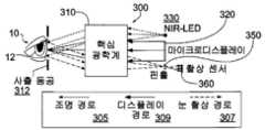
영상 기반의 특징 추적 시스템을 이용한 ET-HMD은 통상 적어도 3개의 고유한 광경로, 즉 조명 경로, 눈 촬상 경로 및 가상 디스플레이 경로를 필요로 한다. 조명 경로를 통해, 눈은, 추적을 위한 암동공 또는 명동공 및/또는 푸르키네(Purkinje) 특징 등의 촬상 특징을 형성하기 위해 통상 근적외선 발광 다이오드(NIR LED)에 의해 조명된다. 촬상 경로를 통해, 추적 특징을 가진 눈 이미지가 특징 검출 및 추적을 위해 포착된다. 디스플레이 경로를 통해, 소형의 디스플레이 장치 상에 표시된 가상 이미지가 정보 표시용 접안 광학계를 통해 형성된다. 본 발명의 혁신 중 하나는, 동일한 핵심 광학계를 통해 이들 3개의 광학 경로를 고유하게 조합할 수 있는 광학 방식이며, 그 동일한 핵심 광학계는 접안, 투사 렌즈 또는 다른 광학계 구조일 수 있다.ET-HMDs using image-based feature tracking systems typically require at least three unique optical paths: an illumination path, an eye imaging path, and a virtual display path. Via the illumination path, the eye is typically illuminated by near-infrared light emitting diodes (NIR LEDs) to form imaging features such as dark or bright pupils for tracking and/or Purkinje features. Through the imaging path, eye images with tracking features are captured for feature detection and tracking. Via the display path, a virtual image displayed on the compact display device is formed through the eyepiece optics for information display. One of the innovations of the present invention is an optical scheme that can uniquely combine these three optical paths through the same core optics, which can be the eyepiece, projection lens or other optical system structure.
예를 들어, 그 양태 중 하나에 있어서, 본 발명은 시선추적용 눈 촬상 광학계를 정보 표시용 디스플레이 광학계와 고유하게 조합할 수 있는 혁신적인 광학 방식과 함께 프리폼(freeform) 광학 기술을 이용할 수 있다. (따라서, 본 발명의 설명과 관련하여 사용되는 것인 "디스플레이 광학계" 및 "촬상 광학계"란 용어는 동일한 물리적 광학계를 칭할 수 있으며, 이 물리적 광학계는 "핵심 광학계"라고도 불려질 수 있다). 선택적으로, 눈 조명 광학계도 조합될 수 있다. 이처럼, 본 발명의 장점 중 하나는, HMD용 광학 시스템과 시선추적용 경로를 구별하여 취급하고 회전 대칭 광학면을 대부분 사용하는 종래의 어프로치에 의해 부여된 한계를 피한다는 것이다. 그러나, 어쩌면 많은 한계가 있더라도, 본 발명에서 개시하는 HMD와 시선추적을 통합하는 광학 방식은 프리폼 광학계에 제한되지 않는다. 본 발명에 따른 ET-HMD 시스템용 핵심 광학계는 종래의 HDM 광학계에 적용될 수 있다.For example, in one of its aspects, the present invention may utilize freeform optics technology with innovative optics that can uniquely combine eye imaging optics for eye tracking with display optics for information display. (Thus, the terms "display optics" and "imaging optics" as used in connection with the description of the present invention may refer to the same physical optics, which may also be referred to as "core optics"). Optionally, eye illumination optics may also be combined. As such, one of the advantages of the present invention is that it avoids the limitations imposed by the conventional approach, which treats the optical system for HMD and the path for eye tracking separately and mostly uses rotationally symmetric optical surfaces. However, although there may be many limitations, the optical method for integrating the HMD and eye tracking disclosed in the present invention is not limited to the free-form optical system. The core optical system for the ET-HMD system according to the present invention can be applied to the conventional HDM optical system.
예시적인 구성에 있어서, 본 발명은 사용자가 보는 이미지를 생성하는 마이크로디스플레이를 포함하는 시선추적 기능의 헤드 탑재형 디스플레이를 제공할 수 있으며, 이 마이크로디스플레이는 디스플레이 광경로 및 이 디스플레이 광경로와 연관된 사출 동공을 구비할 수 있다. 마이크로디스플레이에는 제1면이 배치되고, 사출 동공에는 제2면이 배치될 수 있다. 이미지 센서는 사용자의 눈으로부터 반사된 제2면으로부터의 반사 광선을 수광하도록 구성될 수 있으며, 연관된 센서 광경로를 구비할 수 있다. 또한, 시선추적 기능의 헤드 탑재형 디스플레이는, 디스플레이 광경로를 따라 마이크로디스플레이와 광통신하도록 그리고 센서 광경로를 따라 이미지 센서와 광통신하도록 배치된 디스플레이 광학계를 포함할 수 있다. 디스플레이 광학계는 마이크로디스플레이 및 이미지 센서에 최근접한 선택면을 포함할 수 있고, 마이크로디스플레이와 이미지 센서에 대해, 디스플레이 광경로 및 이미지 센서 광경로가 선택면의 각각의 상이한 부분에 침입하도록 배치될 수 있다. 디스플레이 및 이미지 센서 광경로는 선택면에서 부분적으로 겹칠 수 있다. 디스플레이 및 이미지 센서 광경로는 각각 디스플레이 광학계 및 이미지 센서에서 각각의 광축을 포함할 수 있으며, 이들 축은 동축이거나 서로에 대해 경사질 수 있다. 또한, 시선추적 기능의 헤드 탑재형 디스플레이는 제1면에 조리개를 포함할 수 있으며, 상기 조리개는 센서 광경로를 따른 장소에 배치되어 있는 적어도 하나의 개구(aperture)를 구비한다. 마찬가지로, 시선추적 기능의 헤드 탑재형 디스플레이는 센서와 선택면 사이의 센서 광경로를 따른 장소에 배치되어 있는 적어도 하나의 개구를 구비한 조리개를 포함할 수 있다. 어느 구성이라도, 조리개 또는 개구는 핀홀형 개구를 포함할 수 있다. 일 예시적인 구성에 있어서, 디스플레이 광학계는 프리폼 광학 소자, 회전 대칭 광학 소자 및/또는 프리폼 광학 프리즘을 포함할 수 있다. 디스플레이 광학계는 비구면을 포함할 수 있다.In an exemplary configuration, the present invention may provide a head-mounted display with eye tracking functionality comprising a microdisplay that generates an image viewed by a user, the microdisplay comprising a display light path and an ejection associated with the display light path. A pupil may be provided. A first surface may be disposed on the microdisplay, and a second surface may be disposed on the exit pupil. The image sensor may be configured to receive a reflected light beam from the second surface reflected from the user's eye, and may have an associated sensor optical path. Further, the head mounted display with eye tracking function may include display optics disposed to optically communicate with the microdisplay along the display optical path and optically communicate with the image sensor along the sensor optical path. The display optics may include a selection surface proximate the microdisplay and the image sensor, and for the microdisplay and image sensor, the display light path and the image sensor light path may be arranged to penetrate respective different portions of the selection surface. . The display and image sensor optical paths may partially overlap in select planes. The display and image sensor optical paths may include respective optical axes in the display optics and the image sensor, respectively, which axes may be coaxial or inclined relative to each other. Further, the head-mounted display with eye tracking function may include an aperture on the first surface, the aperture having at least one aperture disposed at a location along the sensor optical path. Likewise, a head mounted display with eye tracking functionality may include an aperture having at least one aperture disposed at a location along the sensor optical path between the sensor and the selection surface. In either configuration, the stopper or aperture may comprise a pinhole-type aperture. In one exemplary configuration, the display optics may include a free-form optical element, a rotationally symmetric optical element, and/or a free-form optical prism. The display optical system may include an aspherical surface.
또한, 시선추적 기능의 헤드 탑재형 디스플레이는 사용자 눈을 조명하기 위해 제2면을 조명하는 광선을 생성하는 광원을 포함할 수 있다. 디스플레이 광학계는 광원으로부터의 광선을 시준하도록 구성될 수 있다. 광원은 디스플레이 광학계의 광축으로부터의 오프축 등의 상이한 장소에 또는 제1면 내에 배치될 수 있다.In addition, the head mounted display of the eye tracking function may include a light source that generates a light beam that illuminates the second surface to illuminate the user's eyes. The display optics may be configured to collimate light rays from the light source. The light source may be disposed in a different location, such as off-axis from the optical axis of the display optics, or in the first surface.
본 발명의 예시적인 실시형태에 대한 전술한 개요 및 이하의 상세한 설명은 첨부하는 도면을 참조할 경우 더 잘 이해될 것이다.
도 1은 회전 대칭 광학 기술에 기초한 종래의 시선추적 기능의 헤드 탑재형 디스플레이(eyetracked head-mounted display, ET-HMD)을 개략적으로 도시하는 도면이다.
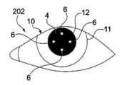
도 2a와 도 2b는 2개의 상이한 IR 조명 전략으로부터의 이미지를 개략적으로 도시하며, 도 2a는 명안 동공의 눈 이미지로서, 4개의 NIR LED가 눈 촬상 광학계의 광축과 거의 동축으로 배치되어 있는 온축 조명 전략에서 야기되는 4개의 섬광을 도시하고, 도 2b는 암안 동공의 눈 이미지로서, 4개의 NIR LED가 눈 촬상 광학계의 광축과 떨어져 배치되어 있는 오프축 조명 전략에서 야기되는 4개의 섬광을 도시한다.
도 3a는 단안식 광학 모듈로서 나타낸, 본 발명에 따른 예시적인 광학 시스템을 개략적으로 도시하는 도면이다.
도 3b는 눈 촬상 유닛과 조명 유닛이 마이크로디스플레이 패널 주위에 배치되어 있는, 본 발명에 따른 예시적인 시스템을 개략적으로 도시하는 도면이다.
도 4는 단안식 광학 모듈로서 나타낸 본 발명에 따른, 프리폼 프리즘 기술에 기초한 예시적인 광학 시스템의 블록도를 개략적으로 도시하는 도면이다.
도 5a 내지 도 5d는 본 발명에 따른 광학 시스루 HMD의 예시적인 설계를 개략적으로 도시하는 도면으로서, 도 5a는 눈 조명 및 촬상 경로를 도시하고, 도 5b는 가상 디스플레이 경로를 도시하며, 도 5c는 눈 조명, 눈 촬상 및 가상 디스플레이 경로가 공유하는 프리폼 프리즘을 도시하고, 도 5d는 시스루 기능을 가능하게 하는, 프리폼 프리즘에 부착된 프리폼 보조 렌즈를 도시한다.
도 6은 도 5d의 2반사 프리폼 프리즘 구조를 이용한, 본 발명에 따른 예시적인 최적화 ET-HMD 구조의 광학 레이아웃과 광선추적을 개략적으로 도시하는 도면이다.
도 7은 본 발명에 따른 예시적인 ET-HMD 광학 시스템의 3D 모델을 개략적으로 도시하는 도면이다.
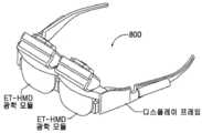
도 8은 도 6과 도 7의 광학 설계에 기초한, 본 발명에 따른 예시적인 양안식 ET-HMD 프로토타입의 모델을 도시하는 도면이다.
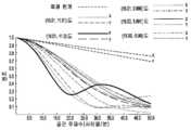
도 9a 내지 도 9d는 도 6의 설계의 4 ㎜ 중심 동공을 갖는 HMD 가상 디스플레이 경로에 있어서 시야 전체에서의 20개 샘플 필드의 다색 변조 전달 함수(MTF)를 나타내는 도면이다.
도 10은 도 6의 설계의 HMD 가상 디스플레이 경로에 있어서 시야 전체의 왜곡 그리드를 나타내는 도면이다.
도 11은 도 6의 설계의 눈 촬상 경로에 있어서 시야 전체에서의 샘플 필드의 다색 변조 전달 함수(MTF)를 나타내는 도면이다.
도 12는 도 6의 설계의 눈 촬상 경로에 있어서 시야 전체의 왜곡 그리드를 나타내는 도면이다.
도 13a 내지 도 13d는 도 6의 설계의 4 ㎜ 중심 동공을 갖는 HMD 시스루 경로에 있어서 30x22도의 중심 시야에 걸친 20개 샘플 필드의 다색 변조 전달 함수(MTF)를 나타내는 도면이다.
도 14는 도 6의 설계의 HMD 시스루 경로에 있어서 시야 전체의 왜곡 그리드를 도시하는 도면이다.
도 15a와 도 15b는 본 발명에 따른, 도 3에 도시한 광학 방식의 예시적인 설계를 도시하는 도면이다.
도 16은 회전 대칭 광학계에 기초한, 본 발명에 따른 도 3에 도시한 광학 방법의 예시적인 구현을 개략적으로 도시하는 도면이다.BRIEF DESCRIPTION OF THE DRAWINGS The foregoing summary and the following detailed description of exemplary embodiments of the present invention will be better understood with reference to the accompanying drawings.
1 is a diagram schematically illustrating a conventional eyetracked head-mounted display (ET-HMD) with an eye-tracking function based on rotationally symmetric optical technology.
Figures 2a and 2b schematically show images from two different IR illumination strategies, and Figure 2a is an eye image of a bright eye pupil, with on-axis illumination with four NIR LEDs positioned nearly coaxial with the optical axis of the eye imaging optics. The four flashes resulting from the strategy are shown, and FIG. 2B is an eye image of the dark pupil, showing the four flashes resulting from the off-axis illumination strategy in which the four NIR LEDs are positioned away from the optical axis of the eye imaging optics.
Fig. 3a schematically shows an exemplary optical system according to the present invention, shown as a monocular optical module;
Fig. 3b schematically shows an exemplary system according to the present invention, in which an eye imaging unit and an illumination unit are arranged around a microdisplay panel;
4 is a diagram schematically illustrating a block diagram of an exemplary optical system based on freeform prism technology, in accordance with the present invention, shown as a monocular optical module.
5A-5D schematically illustrate an exemplary design of an optical see-through HMD according to the present invention, wherein FIG. 5A shows the eye illumination and imaging path, FIG. 5B shows the virtual display path, and FIG. 5C shows the Figure 5d shows a freeform auxiliary lens attached to the freeform prism enabling see-through functionality, showing the freeform prism shared by the eye illumination, eye imaging and virtual display paths.
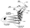
FIG. 6 is a diagram schematically illustrating the optical layout and ray tracing of an exemplary optimized ET-HMD structure in accordance with the present invention, using the two-reflective freeform prism structure of FIG. 5D.
7 is a diagram schematically illustrating a 3D model of an exemplary ET-HMD optical system according to the present invention.
8 is a diagram illustrating a model of an exemplary binocular ET-HMD prototype according to the present invention, based on the optical design of FIGS. 6 and 7 ;
9A-9D are plots showing the multicolor modulation transfer function (MTF) of 20 sample fields across the field of view for an HMD virtual display path with a 4 mm central pupil of the design of FIG. 6 ;
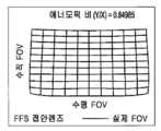
FIG. 10 is a diagram illustrating a distortion grid of the entire field of view in the HMD virtual display path of the design of FIG. 6 .
FIG. 11 is a diagram showing the multicolor modulation transfer function (MTF) of the sample field over the entire field of view in the eye imaging path of the design of FIG. 6 .
Fig. 12 is a diagram showing a distortion grid of the entire field of view in the eye imaging path of the design of Fig. 6;
13A-13D are plots showing the multicolor modulation transfer function (MTF) of 20 sample fields over a central field of view of 30x22 degrees for an HMD see-through path with a 4 mm central pupil of the design of FIG. 6 ;
Fig. 14 is a diagram showing a distortion grid of the entire field of view in the HMD see-through path of the design of Fig. 6;
15A and 15B are diagrams illustrating an exemplary design of the optical scheme shown in FIG. 3, in accordance with the present invention;
Fig. 16 schematically shows an exemplary implementation of the optical method shown in Fig. 3 according to the invention, based on rotationally symmetrical optics;
이제, 같은 요소에 대해서는 전체적으로 같은 도면부호를 지정한 도면을 참조하면, 도 3a은 컴팩트한 ET-HMD 시스템을 실현하기 위한 본 발명에 따른 예시적인 시스템 레이아웃(300)을 개략적으로 도시하고 있다. 본 예시적인 레이아웃(300)에서는, 동일한 핵심 광학계(310)가 눈 촬상, 디스플레이 표시(display viewing) 및/또는 눈 조명의 기능을 수행할 수 있다. 이 단순화는 눈 조명 경로(305), 눈 촬상 경로(307) 및 디스플레이 경로(309) 내의 고유 공역면에 대한 예리한 관찰로부터 유래된다. 또한, 핵심 광학계(310)의 개구부를 따른 서로 다른 부분들이 눈 조명 경로(305), 눈 촬상 경로(307) 및 디스플레이 경로(309)에 이용될 수 있다. 예를 들어, 마이크로디스플레이에 최근접하게 배치된 핵심 광학계(310)의 선택면에서, 눈 조명 경로(305), 눈 촬상 경로(307) 및 디스플레이 경로(309) 중 2개 이상의 경로(예, 눈 촬상 경로(307) 및 디스플레이 경로(309))는 부분적 겹침은 허용되지만 선택면의 각각의 상이한 부분에 침입할 수 있다.Referring now to the drawings in which like elements are generally designated by like reference numerals, FIG. 3a schematically illustrates an
디스플레이 경로(309)에 있어서, 이 상황에서 디스플레이 광학계로서 기능하는 핵심 광학계(310)는 눈(10)이 보는 마이크로디스플레이(320)의 확대 가상 이미지를 형성한다. 마이크로디스플레이 유닛(320)은 이미지 소스로서 역할할 수 있는 임의 유형의 자체 발광 또는 조명하의 픽셀 어레이일 수 있는데, 이것은 LCoS(liquid crystal on silicon) 디스플레이 장치, LDC(liquid crystal display) 패널, OLED(organic light emitting display), FLCoS(ferroelectric liquid crystal on silicon) 장치, DMD(digital mirror device), 또는 이 전술한 유형 또는 다른 유형의 마이크로디스플레이 장치 상에 장착된 마이크로 프로젝터를 포함하나 이들에 한정되지 않으며, 원하거나 필요하다면 마이크로디스플레이(320)와 핵심 광학계(310) 사이에 추가 선택적인 광학계가 설치될 수도 있다. 눈(10)으로부터 무한 또는 유한 거리에 있는 것으로 보일 수 있는 확대 가상 이미지는 마이크로디스플레이(320)의 공역 초점면에 대응한다. 눈 동공(12)은 디스플레이 경로(309)의 사출 동공(312)과 같은 곳에 배치될 수 있다. 동공(12)의 중심(도 3a에 굵은 선으로 표시)을 통과한 디스플레이의 주광선은 마이크로디스플레이(320)에서 필드 높이를 규정하며, 이에 그 광선은 마이크로디스플레이 면에서 분리될 수 있다. 눈 조명 경로(305)에 있어서, 디스플레이/핵심 광학계(310)를 통해 눈을 조명하기 위해 도 3b에 도시하는 바와 같이 하나 또는 복수의 NIR LED(근적외선 발광 다이오드)(330)가 마이크로디스플레이(320) 주위에 탑재될 수 있다. 디스플레이/핵심 광학계(310)는 LED 광을 시준하고, 디스플레이/핵심 광학계(310)를 통해 형성된 복수의 가상 LED 소스를 통해 눈 영역 상에 균일하게 조명된 영역을 형성할 수 있다. 이러한 오프축 조명 구성은 암동공(dark-pupil) 효과를 만들어낼 수 있고, 전방 각막에서 벗어난 반사를 통해 NIR LED(330)의 다중 섬광 이미지를 형성할 수 있다.In the display path 309 , the
눈 촬상 경로(307)에 있어서, 눈 동공(12)은 촬상되어야 하는 대상이 된다. 마이크로디스플레이(320) 주위에는 조리개(340)가 배치될 수 있다. 전술한 마이크로디스플레이(320)와 눈 동공(12)의 동공 필드 관계(pupil-field relationship)를 고려하면, 디스플레이 경로 내의 상이한 대상 필드의 주광선은 눈 촬상 경로(307) 내의 온축 대상점의 주변 광선이 되고, 이에 눈 동공(12) 상의 같은 점을 통과한 모든 광선은 IR 촬상 센서(360) 상의 같은 점에서 촬상될 것이다. 그러나, 이들 광선은 고유 장소에서 마이크로디스플레이 면과 교차한다. 그렇기 때문에, 촬상 경로(307)에 있어서, 조리개(340)는 디스플레이 경로(309)에 영향을 미치지는 않지만 눈 촬상 경로(307) 내에서 눈 이미지를 형성하기 위해 광선을 집광하기에 충분하도록 적절하게 설계되어 마이크로디스플레이(320) 주위에 배치된다. 도 3b에 도시하는 예에서는, 조리개(340)가 핀홀형의 소형 개구(350) 형태로 제공되거나 마이크로디스플레이(320)를 둘러싸는 선택 영역일 수 있다. 개별 촬상 센서(360)는 각각의 핀홀형의 개구(350)와 연관될 수 있다.In the
그 장점 중 하나는 2개 또는 3개의 고유 광학 기능을 조합하는 광학 레이아웃(300)이 HMD 광학계에 적합할 수 있는 사실상 모든 유형의 광학 구조에 적용될 수 있다는 점이다. 예를 들어, 회전 대칭 광학 소자에 기초한 종래의 접안 광학계를 구비한 예시적인 구성이, 도 16과 관련하여 후술하는 바와 설계되었다.One of its advantages is that the
구체적으로 시선추적 기능 양태에 대하여, 시선 이동을 모니터링하는데 이용될 수 있는 여러 상이한 시선추적 기술이 존재하는데 이들은 3가지 카테고리, 즉 전기안구도(electro-oculography), 공막탐지 코일법(scleral search coil), 및 다양한 영상 기반의 특징 추적 어프로치로 구분된다. 이들 방법 중, 포착된 눈 이미지 내의 특징을 검출하여 추적하는 영상 기반의 특징 추적은 시선 이동을 추적하기에 가장 덜 강제적이고 가장 간편한 어프로치일 수 있다.With respect to the eye tracking function aspect specifically, there are several different eye tracking techniques that can be used to monitor eye movement, which fall into three categories: electro-oculography, scleral search coil. , and various image-based feature tracking approaches. Among these methods, image-based feature tracking, which detects and tracks features in captured eye images, may be the least compulsory and easiest approach to tracking gaze movement.
근적외선 NIR 조명하에서, 도 2a와 도 2b에 나타내는 바와 같이, 통상 눈 이미지(201, 202)는 쉽게 식별되고 측정될 수 있는 2유형의 특징을 갖고 있다. 한 특징은 제1 푸르키네 이미지 또는 섬광(6)으로서 알려져 있으며, 도 2b에 도시하는 바와 같이, 각막의 전방면에 의해 형성된 점광원의 반사 이미지이라고 칭해진다. 제2 특징은 눈 동공(12)이다. 도 2a와 도 2b는 IR 조명하의 눈 이미지(201, 202)의 예를 나타내고 있다. IR 조명기, 예컨대 NIR LED(330)의 구성에 종속하여, IR 조명기가 눈 촬상 광학계의 광축과 거의 동축으로 배열되어 있는 온축 조명 전략은 도 2a에 도시하는 명동공(2)이 되고, IR 조명기가 눈 촬상 광학계의 광축에서 떨어져 배치되어 있는 오프축 조명 전략은 도 2b에 도시하는 섬광(6)을 갖는 암동공(4)이 된다. 그래서 동공 및 섬광 특징이 시선 이동 추적에 이용될 수 있다.Under near-infrared NIR illumination, as shown in FIGS. 2A and 2B ,
영상 기반의 특징 추정 방법 중에서, 시선 이동을 동공 중심과 섬광 중심 간의 벡터차에 관련시키는 동공 각막 추적법이 ET-HMD 시스템에서 가장 적합한 어프로치일 수 있다. 이 방법에서는, 하나 또는 복수의 NIR 발광 다이오드(NIR LED), 예컨대 NIR LED(330)가 눈(10)을 조명하는데 이용될 수 있으며, 조명하의 눈(10)은 적외선 CCD 등의 촬상 센서(360)에 의해 촬상될 수 있다. 눈 동공(12), 제1 푸르키네 이미지(또는 섬광) 및/또는 홍채(11)는 동시에 또는 개별로 추적될 수 있다. 각각의 NIR LED(330)가 섬광(6) 또는 제1 푸르키네 이미지를 형성할 수 있다. 동공(12) 및 제1 푸르키네 특징은 안구 회전과 비례하여 그리고 서로 다르게 움직인다. 2개의 특징 간의 벡터차는 눈(10)의 주시점(point-of-regard)을 결정하는데 이용될 수 있다. 어느 정도까지는 이 방법이 HMD 시스템에서의 헬멧 슬리피지(helmet slippage)를 견딜 수 있는데, 이 헬멧 슬리피지는 눈(10)에 대해 촬상 센서(360)의 방위 변화를 일으켜서 시선 이동을 혼란스럽게 하는 것이다.Among the image-based feature estimation methods, the pupil corneal tracking method, which relates gaze movement to the vector difference between the pupil center and the scintillation center, may be the most suitable approach in the ET-HMD system. In this method, one or more NIR light emitting diodes (NIR LEDs), such as
중요한 양태 중 다른 것에 있어서, 본 발명은 시스루 기능을 갖는 초컴팩트한 경량의 ET-HMD를 실현하기 위해 핵심 광학계(310) 내에 프리폼 광학 기술을 이용할 수 있다. 도 4는 프리폼 광학 기술에 기초한, 본 발명에 따른 컴팩트한 시선추적 기능의 HMD 설계에 대한 예시적인 어프로치의 블록도(400)를 도시한다. 일 예시적인 구현에 있어서, 쐐기형(wedge-shaped) 프리폼 프리즘(410) 또는 도광 유형의 프리폼 프리즘을 핵심 광학계(310) 내에 사용함으로써, 회전 대칭 소자를 이용한 설계와 비교하여, 광선 경로가 다면 프리즘 구조 내에서 꺽일 수 있고, 디스플레이 광학계의 전체 부피 및 중량의 감소를 돕는다. 프리폼 광학 기술을 적용함으로써, HMD 광학계 및 시선추적의 기능을 컴팩트한 형태로 완전 통합시킬 수 있다. 프리폼 프리즘(410)은 경량 및 저비용을 위해 성형 가능 플라스틱으로 구성될 수 있다.In another of the important aspects, the present invention may utilize preform optics technology within the
본 어프로치에서는, 프리폼 프리즘(410)이 2개 이상의 고유 광학 기능을 수행할 수 있다. 첫째, 프리폼 프리즘(410)은 눈 촬상 경로(407) 내에서, 사용자의 NIR 조명하의 눈 이미지(410)를 포착하고 포착된 눈 이미지(410)을 이용해 시선 이동을 추적하는 핵심 소자로서 역할할 수 있다. 렌즈 구조 내에 통상 회전 대칭 광학면을 채용하고 통상 촬상 렌즈가 검출기(460)와 동일선 상에 있는 것을 필요로 하는 종래의 촬상 시스템과 달리, 프리폼 프리즘(410)은 이미지 검출기(460)가 프리폼 프리즘(410)의 측면에 배치될 수 있도록 단일 소자 내에서 광경로를 꺽는다. 둘째, 동일한 프리폼 프리즘(410)이 디스플레이 경로(409) 내의 마이크로디스플레이(420) 상에서 이미지를 표시하는 디스플레이 표시용 광학계로서 역할할 수 있다. 셋째, 프리폼 프리즘(410)은 조명 경로(305)에서, NIR LED(430)의 하나 또는 복수개로부터의 광을 시준하는 핵심 소자로서 역할할 수 있다. 이와 다르게, NIR LED는 프리즘(410)(또는 핵심 광학계(310))을 통과하는 일 없이 직접 눈 영역을 조명할 수 있다. 어떤 경우에서도, NIR LED(430)는 눈 영역을 균일하고 비침입적으로 조명할 수 있고, 시선추적을 위해 촬상되어야 하는 결정적인 특징(예, 섬광(6) 및 암동공(4))을 형성할 수 있다. 마지막으로, 광학적 시스루 ET-HMD 시스템이 실세계의 직시(direct view)가 중요한 애플리케이션에 필요하다면, 프리즘(410)은 프리폼 교정 렌즈(415)와 결합될 수 있다. 프리폼 교정 렌즈(415)는 프리즘(410)에 의해 도입되는 시선측 축편위 및 바람직하지 않은 수차를 교정할 수 있고, 실세계 뷰(411)에 대한 주위의 암측화(peripheral obscuration)를 낮게 하고 왜곡을 최소화한 시스템(400)의 시스루 기능을 가능하게 한다. 전반적으로, 본 발명의 고유 광학 방식은 동일한 프리폼 프리즘(410)을 통해, 눈 촬상(407) 및 가상 디스플레이(409) 및 선택적으로 눈 조명(405)에 대한 광학 경로의 조합을 가능하여 하고, 최소의 하드웨어 비용으로 시선추적 및 디스플레이의 기능을 달성할 수 있다.In this approach, the
실시예 1Example 1
본 발명에 따른 예시적인 제1 구성(500)은 도 5a 내지 도 5d에 도시하는 바와 같이, 2개의 반사면을 갖는 쐐기형의 프리폼 프리즘(510)을 이용한다. 본 실시형태에서는, 프리폼 프리즘(510)이 다음과 같이 (1) 촬상될 눈 영역을 균일하고 비침입적으로 조명하기 위해 하나 또는 복수의 NIR LED(530)로부터의 광을 시준하는 조명 광학계로서, (2) 시선 이동 추적을 가능하게 하기 위하여 NIR 조명하의 눈 이미지를 포착하는 눈 촬상 광학계의 핵심 소자로서, (3) 마이크로디스플레이(520) 상에 이미지를 표시하기 위한 HMD 시스템의 접안 광학계로서의 3가지만큼 많은 핵심 기능을 수행할 수 있다. 이들 3개의 고유 광학 경로는 시선추적 및 디스플레이의 기능을 달성하기 위하여 동일한 프리폼 프리즘(510)에 의해 조합될 수 있다. 부가적으로, 프리폼 교정 렌즈와 결합될 때의 동일한 프리즘(510)은 광학 시스루 HMD 시스템의 시스루 기능을 가능하게 한다. 이와 다르게, 프리폼 프리즘(510)은 조명광으로서의 핵심 기능을 생략할 수도 있다.An exemplary
쐐기형 프리폼 프리즘(510)은 3개의 광학면을 포함할 수 있으며, 이들 중 적어도 하나는 회전 대칭성의 유무에 관계없이 비구면일 수 있다. 본 발명의 한가지 혁신은 단일 프리폼 프리즘(510)을 통해 2개 또는 3개의 고유 광학 경로(즉, 눈 조명 경로(505), 눈 촬상 경로(507), 및 디스플레이 경로(509) 중 2개 이상)를 고유하게 조합할 수 있는 광학 어프로치이다. 도 5a는 프리폼 프리즘(510)을 포함하는 눈 조명 및 촬상 광학계의 개략 설계를 도시하고 있다. 조명 경로(505)에 있어서, NIR LED(530)로부터 출사된 광선은 먼저 면(3)에서 굴절된 다음, 면(1', 2)에서 2회 연속 반사되어 마침내 면(1)을 투과하여 눈(10)에 도달한다. 면(1')에서의 반사는 내부 전반사(total internal reflection, TIR)의 조건을 만족할 수 있다. LED(530)에 의해 출사된 광은 프리즘(510)에 의해 시준되어, 눈(10)에 대해 균일한 조명이 될 수 있다. 그리고 NIR 조명하의 눈(10)은 IR 촬상 센서(560)에 의해 촬상될 수 있다. 눈 촬상 경로(507)에 있어서, 눈(10)에서 벗어나 산란된 광선은 먼저 면(1)에서 굴절된 다음, 면(2', 1)에서 2회 연속 반사되어 마침내 면(3)을 투과하여 센서(560)에 도달할 수 있다. 눈 촬상의 광학 성능을 향상시키기 위해 프리즘(510)의 면(3)과 촬상 센서(560) 사이에 추가 렌즈(562)가 삽입될 수 있다. 촬상 센서(560)에 의해 수광된 빛을 가두기 위해 소형 개구의 조리개(550)가 렌즈(562) 근방에 또는 내부에 배치될 수 있다.The wedge-shaped
도 5b는 만족할만할 시거리에서 가상 이미지를 형성하는, 마이크로디스플레이(520) 상의 이미지를 확대시키기 위해 프리폼 프리즘(510)을 사용하는 HMD 광학계의 디스플레이 경로(509)를 개괄적으로 도시하고 있다. 마이크로디스플레이(520) 상의 점에서 출사된 광선은 먼저 프리폼 프리즘(510)의 면(3)에서 굴절된 다음, 면(1', 2)에서 2회 연속 반사되어 마침내 면(1)을 투과하여 시스템(500)의 사출 동공(512)에 도달한다. 면(1')에서의 반사는 TIR의 조건을 만족할 수 있다. 다중 소자를 필요로 하는 것이 아니라, 광학 경로가 프리즘 구조 내에서 사실상 꺽여진다. 디스플레이 경로(509)의 광학 성능을 더욱 향상시키기 위해 프리즘(510)의 면(3)과 마이크로디스플레이(520) 사이에 추가 렌즈가 삽입될 수도 있다.5B schematically illustrates the
도 5c는 통합 시스템(500)을 개략적으로 도시하고 있으며, 이 통합 시스템은 조명, 촬상 및 디스플레이 광학계가 동일한 프리즘(510)을 포함하고, 고화질의 눈 이미지를 형성하기 위해 마이크로디스플레이(520)의 가장자리(540) 주위에 핀홀형의 조리개(550)가 배치되어 있다. 조리개 및 LED 구성의 일례가 도 5c에 예시되어 있다. 마이크로디스플레이(520)의 주위부의 다른 장소에 조리개(550)와 LED(530)가 배치될 수도 있다는 점도 주목할만 하다. 또한, 조리개(550)와 LED(530)는 마이크로디스플레이(520)와 동일한 평면에 있거나 있지 않을 수도 있다. 시스템 성능을 향상시키기 위해 조명 경로(505), 눈 촬상 경로(507) 및 디스플레이 경로(509) 중 하나 이상의 경로에 추가 렌즈가 사용될 수도 있다. 또한, 마이크로디스플레이(520)에 최근접한 면, 즉 면(3)에서, 조명 경로(505), 눈 촬상 경로(507), 및 디스플레이 경로(509)는 (부분적으로는 겹칠 수 있지만) 면(3)의 각각의 상이한 부분에 침입할 수 있다.5C schematically shows an
시스루 기능을 가능하게 하기 위해, 프리즘(510)의 면(2)은 하프 미러(half mirror)로서 코팅될 수 있다. 실세계 장면으로부터의 광선은 투과되는 반면, 마이크로디스플레이(520)로부터의 광선은 면(2)에서 반사될 수 있다. 도 5d는 2개의 프리폼 면(4, 5)으로 이루어진 프리폼 보조 렌즈(515)를 개략적으로 도시하고 있으며, 이 프리폼 보조 렌즈는 프리폼 프리즘(510)에 의해 도입되는 시선측 편위 및 수차를 실세계 뷰 경로(511)에 대해 교정하기 위해 프리즘(510)와 결합되는 것이다. 보조 렌즈(515)의 면(4)은 대개 프리즘(510)의 면(2)과 처방(prescription)이 같으며, 보조 렌즈(515)의 면(5)은 축편위 및 수차를 교정하는데 최적화되어 있다. 보조 렌즈(515)는 전체 시스템의 풋프린트 또는 중량을 현저하게 상승시키지 않는다. 전체적으로, 예시적인 시스템(500)은 경량의, 컴팩트하고, 강고하며, 시선추적 기능을 갖는 HMD 솔루션에, 기존의 어떤 HMD 어프로치가 잠재적으로 만들어 낼 수 있는 것보다 덜 거슬리고, 설계의 컴퓨터 분석을 통해 추가 검증되는 폼팩트를 제공한다.To enable a see-through function, the
도 6은 도 5에 도시한 2 반사의 쐐기형 프리폼 프리즘(510)에 기초한 최적화 시스템의 2차원 광학 레이아웃을 개략적으로 도시하고 있다. 본 구현에 있어서, 촬상 렌즈(562)는 눈 촬상 경로(507)의 성능을 향상시키는데 이용될 수 있다. 조리개(550)는 프리즘(510)의 면(3)에 근접하게 배치될 수 있다. 마이크로디스플레이(520) 주위에는 NIR LED(530)가 배치될 수 있다. 도 7은 도 5d의 예시적인 광학 시스템의 3D 모델(700)을 개략적으로 도시하고, 도 8은 도 6과 도 7에 도시한 광학 설계에 기초한 양안식 ET-HMD 프로토타입(800)의 3D 모델을 개략적으로 도시하고 있다. 전체 시스템의 사양은 표 1에 열거한다.FIG. 6 schematically shows a two-dimensional optical layout of an optimization system based on a wedge-shaped
[표 1] 광학 시스템 사양[Table 1] Optical system specifications

프리폼 프리즘(510)의 예시적인 광학 처방법에 대해서는 면(1, 2, 3)마다 표 2 내지 표 4에 각각 열거한다. 프리즘(510)의 3개의 광학면 중, 면(1)은 애너모픽 비구면(anamorphic aspheric surface, AAS)이다. AAS면의 새그(sag)는 다음과 같이 정의된다.Exemplary optical formulations of the

여기서, z는 국소 x, y, z 좌표계의 z축을 따라 측정된 프리폼 면의 새그이고, cx와 cy는 각각 x축과 y축의 정점 곡률이며, Kx와 Ky는 각각 x축과 y축의 원뿔곡선 상수(conic constant)이고, AR, BR, CR 및 DR은 원뿔곡선으로부터의 4차, 6차, 8차 및 10차 변형의 회전 대칭 성분이며, AP, BP, CP, 및 DP는 원뿔곡선으로부터의 4차, 6차, 8차 및 10차 변형의 비회전 대칭 성분이다.where z is the sag of the preform plane measured along the z axis of the local x, y, z coordinate system, cx and cy are the vertex curvatures of the x and y axes, respectively, and Kx and Ky are the x and y axes, respectively. are the conic constants of the axes, AR, BR, CR, and DR are the rotationally symmetric components of the 4th, 6th, 8th, and 10th transformations from the conic, and AP, BP, CP, and DP are the cones Non-rotationally symmetric components of the 4th, 6th, 8th and 10th transformations from the curve.
프리즘(510)의 면(2)은 다음과 같이 정의되는 XY 다항식 면(polynomial surface)일 수 있다.The

여기서, z는 국소 x, y, z 좌표계의 z축을 따라 측정된 프리폼 면의 새그이고, c는 정점 곡률(CUY)이며, k는 원뿔곡선 상수이고, Cj는 xmyn의 계수이다.where z is the sag of the preform face measured along the z-axis of the local x, y, z coordinate system, c is the vertex curvature (CUY), k is the conic constant, and Cj is the coefficient ofx m yn .
면(3)은 회전 대칭 키노폼 회절 광학 소자를 갖는 비구면일 수 있는데, 그 비구면의 새그는 다음과 같이 정의될 수 있다.The

여기서, z는 국소 x, y, z 좌표계의 z축을 따라 측정된 면의 새그이고, c는 정점 곡률이며, k는 원뿔곡선 상수이고, A 내지 J는 각각 4차, 6차, 8차, 10차, 12차, 14차, 16차, 18차 및 20차 변형 계수이다.where z is the sag of the plane measured along the z axis of the local x, y, and z coordinate system, c is the vertex curvature, k is the conic constant, and A to J are the 4th, 6th, 8th, and 10th, respectively. The first, 12th, 14th, 16th, 18th, and 20th order strain coefficients.
[표 2] 프리폼 프리즘의 면(1)의 광학면 처방[Table 2] Optical surface prescription of the surface (1) of the freeform prism

[표 3] 프리폼 프리즘(510)의 면(2)의 광학면 처방[Table 3] Optical surface prescription of the surface (2) of the


[표 4] 프리폼 프리즘(510)의 면(3)의 광학면 처방[Table 4] Optical surface prescription of the surface (3) of the

프리폼 교정 렌즈(515)의 면(5)의 예시적인 광학 처방에 대해서는 표 5에 열거한다. 렌즈(515)의 면(4)은 프리즘(510)의 면(2)과 처방이 같고, 렌즈(515)의 면(5)은 면(2)와 같은 수학식으로 정의된 XY 다항식 면이다.Exemplary optical formulations of
[표 5] 프리폼 교정 렌즈의 면(5)의 광학면 처방[Table 5] Optical surface prescription of surface (5) of preform corrective lens


예시적인 설계의 디스플레이 측에 있어서, 프리즘(510)은 46도의 대각선 FOV 또는 수평 40도 및 수직 22도를 제공한다. 그것은 ~8 ㎛의 픽셀 사이즈 및 0.9" 이하의 대각선 사이즈를 갖는 마이크로디스플레이(520)를 지원한다. 제조된 프로토타입에서는, 16:9의 종횡비 및 1920x1200 픽셀의 해상도를 갖는 0.86" 마이크로디스플레이가 사용되었다.On the display side of the exemplary design, the
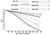
예시적인 설계는 높은 이미지 콘트라스트 및 해상도를 실현한다. 도 9a 내지 도 9d는 4 ㎜ 중심의 동공을 갖는 HMD 경로에 있어서 시야 전체에서의 20개 샘플 필드의 다색 변조 전달 함수(MTF)를 나타내고 있다. MTF 곡선은 50 lps/㎜의 컷오프 해상도(10 ㎛ 픽셀 해상도와 등가)에서 0.2의 평균 콘트라스트와 35 lps/㎜의 컷오프 해상도(대략 15 ㎛ 픽셀 해상도와 등가)에서 0.3보다 높은 평균 콘트라스트를 나타낸다. 도 10은 가상 디스플레이 경로의 왜곡 그리드도 나타내고 있다.The exemplary design realizes high image contrast and resolution. 9A-9D show the multicolor modulation transfer function (MTF) of 20 sample fields across the field of view for an HMD path with a pupil centered at 4 mm. The MTF curve shows an average contrast of 0.2 at a cutoff resolution of 50 lps/mm (equivalent to 10 μm pixel resolution) and an average contrast higher than 0.3 at a cutoff resolution of 35 lps/mm (equivalent to approximately 15 μm pixel resolution). 10 also shows a distortion grid of the virtual display path.
눈 촬상 및 조명 측에 있어서, 프리폼 프리즘(510)을 통해 균일하게 조명된 눈 영역을 형성하기 위해 이미지 소스 주변에 하나 이상의 NIR LED(530)가 배치된다. 프리폼 프리즘(510)은 수평 및 수직 방향 각각에 있어서 대략 30 ㎜ x 20 ㎜의 눈 영역에 대해 균일한 조명을 제공하는 것이 가능하다. NIR 조명하의 눈 영역은 고해상도의 NIR 센서(460)에 의해 포착될 수 있다. 촬상된 영역은 시선 이동을 추적하기에 충분하다. 눈 촬상 경로의 해상 가능한 픽셀 크기는 약 ~10 ㎛이다. 도 11은 눈 촬상 경로의 다색 변조 전달 함수(MTF)를 나타내고 있다. MTF 곡선은 50 lps/㎜의 컷오프 해상도(10 ㎛ 픽셀 해상도와 등가)에서 0.1의 평균 콘트라스트와 30 lps/㎜의 컷오프 해상도(대략 16 ㎛ 픽셀 해상도와 등가)에서 0.25보다 높은 평균 콘트라스트를 나타낸다. 도 12는 눈 촬상 경로의 왜곡 그리드도 나타내고 있다.On the eye imaging and illumination side, one or
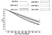
시스템(500)의 시스루 측에 있어서, 결합된 프리즘(510)와 프리폼 교정 렌즈(515)는 대략 100도의 대각선 FOV, 또는 수평 80도 및 수직 50도를 제공한다. 시스루 FOV는 향상된 상황 인식을 위해 가상 디스플레이 FOV보다 훨씬 크게 설계된다. 시스루 시스템의 아이박스 사이즈는 사용 편의성 및 시각적 편안함을 더욱 향상시키기 위해 가상 디스플레이 시스템보다 더 크게 최적화되어 있다. 이 설계의 실시형태는 높은 이미지 콘트라스트 및 해상도를 실현한다. 도 13a 내지 도 13d는 4 ㎜ 중심 동공을 갖는 시스루 경로에 있어서 중심 30x22도의 시야에 걸친 20개 샘플 필드의 다색 변조 전달 함수(MTF)를 나타내고 있다. MTF 곡선은 대략의 회절 한계 성능을 나타내고 있다. 도 13a 내지 도 13d에 있어서, 0.5 사이클/min은 원호형 공간 해상도의 1분에 대응하여 20/20 비전(vision)의 분해성이며, 1 사이클/min은 원호형 공간 해상도의 0.5분에 대응하여 20/15 비전의 분해성이다. 샘플 필드 전체의 평균 MTF는 0.5 사이클/min의 컷오프 해상도(1분의 원호 각도 해상도와 등가)에서 0.5보다 크고, 평균 콘트라스트는 1 사이클/min의 컷오프 해상도(0.5분의 원호 각도 해상도와 등가)에서 0.4보다 크다. 전체 80x50 시스루 FOV에 대한 평균 MTF는 0.5 사이클/min의 컷오프 주파수에서 0.35보다 크다. 도 14는 전체 FOV에 대한 시스루 디스플레이 경로의 왜곡 그리드도 나타내고 있다. 중심 40x22도에서의 왜곡은 1% 미만이고, 전체 시야에 걸친 평균은 8% 미만이다.On the see-through side of
실시예 2Example 2
도 15a와 도 15b는 본 발명의 제2 구성의 예시적인 설계를 개략적으로 도시하고 있는데, 이 구성에서는 촬상 시스템(1500)의 조리개(1540)가 마이크로디스플레이(1520)를 둘러쌀 수 있다. 마이크로디스플레이 평면은 3개의 영역, 즉 IR 센서(1560)에 의해 광선을 집광시켜 IR 센서(1560) 상에서 눈을 촬상하는 조리개(1540)로서 역할할 수 있는 IR 투과 영역(1527)과, IR 광선이 IR 센서(1560)에 도달하는 것을 막는 활성 디스플레이 영역에 대응하는 마이크로디스플레이(1520)의 활성 영역(비투과성)과, 역시 광선이 IR 센서(1560)에 도달하는 것을 막는 마이크로디스플레이의 물리적 프레임에 대응하는, IR 투과성 및 마이크로디스플레이 영역 사이의 제3의 비투과성 프레임(1523)으로 구분된다. 촬상 시스템(1500)에 있어서, 프리즘(1510), 마이크로디스플레이(1520), 및 IR 센서(1560)의 각각의 광축은 동축일 수 있다. 이 경우에, IR 센서(1560)는 눈 동공의 이미지를 포착하기 위해 마이크로디스플레이(1520) 뒤에 배치될 수 있다. IR 센서(1560)로부터 프리즘(1510)까지의 거리는 프리폼 프리즘(1510)를 통과한 눈 동공의 이미지 위치에 종속되며, 궁극적으로는 디스플레이 경로의 설계에 종속된다. 예를 들어, 프리폼 프리즘(1510)이 디스플레이 공간에서 텔레센트릭으로 또는 텔레센트릭에 가깝게 설계된다면, 주광선은 서로 거의 평행하고 마이크로디스플레이(1510)과 교차하기 전에 마이크로디스플레이 면에 직교할 것이다. 이것은 프리즘(1510)을 통과한 눈 동공의 이미지가 무한 거리에 또는 실질적으로 원거리에 위치하는 것을 의미한다. 이 경우에, 도 15a에 도시하는 바와 같이, 눈 촬상 경로의 전체 길이를 줄이고 양호한 화질을 달성하기 위해서는 IR 센서(1560)와 프리즘(1510) 사이에 하나 이상의 추가 촬상 렌즈(1562)가 삽입될 필요가 있다.15A and 15B schematically illustrate an exemplary design of a second configuration of the present invention, in which an
한편, 프리폼 프리즘(1510)이 비텔레센트릭으로 설계된다면(즉, 주광선이 프리즘(1510) 뒤에서 얼마의 단거리 점에서 집속됨), 눈 동공은 프리즘(1510)에 의해 상당히 가까운 거리에서 촬상되고 IR 센서(1560)은 추가 촬상 렌즈(1562)의 필요성 없이 프리즘(1510) 뒤에 바로 배치될 수 있다. 실제로, 텔레센트릭성 또는 근접 텔레센트릭성의 조건은, 가상 이미지가 전체 FOV에 걸쳐 더 균일하게 보이기 때문에 디스플레이 경로를 설계할 경우에 종종 바람직할 수 있다. 이 조건은 마이크로디스플레이(1520)가 협각 내에서만 광을 출사하거나 반사하는 경우(예, LCoS 유형의 마이크로디스플레이 등의 장치)에 필요할 수 있다. 마이크로디스플레이(1520)가 넓은 출사각을 제공할 경우(예, OLED), 텔레센트릭성 조건이 완화될 수 있다.On the other hand, if the
NIR LED는 도 3b에 도시한 바와 같이 마찬가지로 조리개(1540) 주위에 배치될 수도 있고, 또는 이와 다르게 NIR LED(1530)는 프리즘(1510)의 가장자리 주위에 배치되어 도 15a에 도시하는 바와 같이 눈(10)을 직접 조명할 수도 있다. 더욱이, 프리즘(1530)을 사용하지 않고서 눈(10)을 직접 조명하기 위해 프리즘(1510)의 가장자리 주위의 NIR LED(1530)는 예컨대 도 5a 내지 도 6 또는 도 16에 도시한 것을 비롯해 본 발명의 기타 구성으로 구현될 수 있다.The NIR LEDs may likewise be disposed around the
실시예 3Example 3
도 16은 핵심 광학계(310)에 대해 회전 대칭 광학계를 사용하는, 도 3에 도시한 광학 방식의 예시적인 설계(600)를 개략적으로 도시하고 있다. 컴팩트한 프리폼 기반의 프리즘(510)을 사용하는 대신에, 디스플레이 표시, 눈 촬상 및 눈 조명을 위한 핵심 광학계(310)로서 4개 소자의 표시용 광학계(1610)를 이용한다. 광학계(1610)의 초점면에 마이크로디스플레이(1620)가 배치될 수 있다. 이미지 소스(1620) 주위에는 하나의 광원(1630)(NIR-LED 등)이 배치될 수 있다. 촬상 센서(1660) 상에 눈 이미지를 형성하기 위해 이미지 소스(1620)의 가장자리 주위에는 핀홀형의 조리개(1640) 및 마이크로촬상 렌즈(1662)도 배치될 수 있다. 상이한 애플리케이션을 위해 필요하다면 이미지 소스(1620) 주위에 추가 광원(1630)과 촬상 서브시스템(마이크로촬상 렌즈(1662)와 촬상 센서(1660))가 배치될 수 있다. 예시적인 설계(1600)에 있어서, 디스플레이 광학계(1610)와 마이크로디스플레이(1620)의 각 광축은 동축일 수 있고, 촬상 센서(1660), 광원(1630) 및 마이크로디스플레이(1620) 중 하나 이상의 각각의 광축이 서로에 대해 경사지고/지거나 편심될 수 있다. 프리폼 구성과 마찬가지로, 마이크로디스플레이(1620)에 최근접한 면인 면(8)에 있어서, 예컨대 촬상 경로와 디스플레이 경로 사이에 나타내는 바와 같이 부분적으로는 겹쳐지지만, 조명 경로, 눈 촬상 경로, 및 디스플레이 경로는 면(8)의 각각의 상이한 부분에 침입한다.FIG. 16 schematically depicts an exemplary design 600 of the optical scheme shown in FIG. 3 using rotationally symmetric optics for the
표시용 광학계(1610)는 40도의 대각선 FOV, 2 ㎜의 눈동자 거리 및 2 ㎜의 눈동공 사이즈를 제공할 수 있으며, 0.8" 이하의 대각선 사이즈를 가진 촬상 센서(1620)를 지원할 수 있다. 표시용 광학계를 통해 균일하게 조명된 눈 영역을 형성하기 위해 마이크로디스플레이(1620) 주위에 하나 이상의 NIR LED(1630)가 배치될 수 있다. 표시용 광학계(1610)는 대략 15 ㎜ x 15 ㎜의 눈 영역에 대해 균일한 조명을 제공하는 것이 가능하다. 동일한 조명하의 영역은 고해상도의 NIR 센서(1630)에 의해 포착될 수 있다. 촬상된 영역은 시선 이동을 추적하기에 충분하다.The display
설계(1600)의 예시적인 광학 처방에 대해서는 표 6 내지 표 9에 열거한다.Exemplary optical formulations of
[표 6] 표시용 광학계(1610)의 광학면 처방[Table 6] Optical surface prescription of the optical system for

[표 7] 촬상 렌즈(1662)의 광학면 처방[Table 7] Optical surface prescription of the

면(11, 12)은 다음과 같이 정의된 비구면의 새그를 갖는 비구면일 수 있다.The

여기서, z는 국소 x, y, z 좌표계의 z축을 따라 측정된 면의 새그이고, c는 정점 곡률이며, k는 원뿔곡선 상수이고, A 내지 J는 각각 4차, 6차, 8차, 10차, 12차, 14차, 16차, 18차 및 20차 변형 계수이다.where z is the sag of the plane measured along the z axis of the local x, y, and z coordinate system, c is the vertex curvature, k is the conic constant, and A to J are the 4th, 6th, 8th, and 10th, respectively. The first, 12th, 14th, 16th, 18th, and 20th order strain coefficients.
[표 8] 촬상 렌즈의 면(11)의 광학면 처방[Table 8] Optical surface prescription of the

[표 9] 촬상 렌즈의 면(12)의 광학면 처방[Table 9] Optical surface prescription of the

당업자에게는 본 발명의 이러한 장점들 및 기타 장점이 전술한 상세한 설명으로부터 명백해질 것이다. 따라서, 당업자라면 본 발명의 넓은 발명 개념에서 벗어나는 일 없이 전술한 실시형태에 대해 변화 또는 변형이 이루어질 수 있다고 생각할 것이다. 따라서, 본 발명은 여기에 설명한 특정 실시형태에 제한되는 것이 아니라 특허청구범위에 기재하는 본 발명의 범주 및 사상 내에 있는 모든 변화 또는 변형을 포함하는 것을 목적으로 한다.These and other advantages of the present invention will become apparent to those skilled in the art from the foregoing detailed description. Accordingly, it will be appreciated by those skilled in the art that changes or modifications may be made to the above-described embodiments without departing from the broad inventive concept of the present invention. Accordingly, the present invention is not intended to be limited to the specific embodiments described herein, but to cover all changes or modifications falling within the scope and spirit of the invention as set forth in the appended claims.
Claims (25)
Translated fromKorean사용자가 보는 이미지를 생성하며, 디스플레이 광경로 및 이 디스플레이 광경로와 연관된 사출 동공(exit pupil)을 구비하는 마이크로디스플레이;
상기 마이크로디스플레이에 배치된 제1면 및 상기 사출 동공에 배치된 제2면;
상기 제2면에 위치하는 사용자의 눈으로부터 반사된, 상기 제2면으로부터의 반사 광선(reflected optical radiation)을 수광하도록 구성되며, 연관된 센서 광경로를 구비하는 이미지 센서;
광선을 생성하고 사용자의 눈의 조명을 달성하기 위해 상기 제2면을 조명하도록 구성된 광원으로서, 상기 광원은 이 광원과 연관된 조명 광경로를 구비하고, 상기 제1면에 근접 배치되는 것인, 광원; 및
1) 상기 디스플레이 광경로를 따라 상기 마이크로디스플레이와, 2) 상기 조명 광경로를 따라 상기 광원과, 그리고 3) 상기 센서 광경로를 따라 상기 이미지 센서와 광통신하도록 배치되는 디스플레이 광학계로서, 상기 디스플레이 광학계는 상기 마이크로디스플레이, 상기 이미지 센서, 및 상기 광원에 최근접한 선택면을 구비하며, 상기 디스플레이 광학계는 상기 광원으로부터 광선을 수광하고 그 광선을 상기 제2면에 투과시키도록 배치되는 것인, 상기 디스플레이 광학계
를 포함하고
상기 이미지 센서 및 상기 광원은, 상기 마이크로디스플레이에 근접하고 상기 디스플레이 광학계의 상기 선택면과 대면하는 위치에 배치되고,
상기 사출 동공에 최근접하고 상기 사출 동공과 대면하여 배치된, 상기 디스플레이 광학계의 표면은, 애너모픽 비구면(anamorphic aspheric surface, AAS)을 포함하며, 상기 AAS의 새그(sag)는,

의 수학식에 의해 정의되며,
상기 수학식에서, z는 국소 x, y, z 좌표계의 z축을 따라 측정된 상기 AAS의 새그이고, cx와 cy는 각각 x축과 y축의 정점 곡률이고, Kx와 Ky는 각각 x축과 y축의 원뿔곡선 상수(conic constant)이고, AR, BR, CR 및 DR은 상기 원뿔곡선으로부터의 4차, 6차, 8차 및 10차 변형의 회전 대칭 성분이며, AP, BP, CP, 및 DP는 상기 원뿔곡선으로부터의 4차, 6차, 8차 및 10차 변형의 비회전 대칭 성분인 것인, 시선추적 기능의 헤드 탑재형 디스플레이.In the head-mounted display of the eye-tracking function (eye-tracked head-mounted display),
a microdisplay that generates an image viewed by a user, the microdisplay having a display light path and an exit pupil associated with the display light path;
a first surface disposed on the microdisplay and a second surface disposed on the exit pupil;
an image sensor configured to receive reflected optical radiation from the second surface reflected from an eye of a user positioned on the second surface, the image sensor having an associated sensor optical path;
a light source configured to illuminate the second surface to produce a light beam and achieve illumination of a user's eye, the light source having an illumination optical path associated with the light source and disposed proximate to the first surface ; and
1) a display optical system disposed in optical communication with the microdisplay along the display optical path, 2) the light source along the illumination optical path, and 3) the image sensor along the sensor optical path, the display optical system comprising: the display optical system having the microdisplay, the image sensor, and a selection surface proximate to the light source, wherein the display optical system is arranged to receive a light beam from the light source and transmit the light beam to the second surface
includes
The image sensor and the light source are disposed in a position adjacent to the microdisplay and facing the selection surface of the display optical system,
A surface of the display optical system, disposed closest to the exit pupil and facing the exit pupil, includes an anamorphic aspheric surface (AAS), wherein a sag of the AAS includes:
is defined by the formula of
In the above equation, z is the sag of the AAS measured along the z-axis of the local x, y, and z coordinate system, cx and cy are the vertex curvatures of the x-axis and y-axis, respectively, and Kx and Ky are the x-axis, respectively. and conic constants of the y-axis, AR, BR, CR, and DR are rotationally symmetric components of the 4th, 6th, 8th and 10th transformations from the conic, AP, BP, CP, and wherein DP is the non-rotationally symmetric component of the 4th, 6th, 8th and 10th order deformations from the conic.
상기 디스플레이 광경로 및 이미지 센서 광경로는 상기 선택면에서 부분적으로 겹치는 것인 시선추적 기능의 헤드 탑재형 디스플레이.The method of claim 1,
wherein the display light path and the image sensor light path partially overlap on the selection surface.
상기 디스플레이 광학계는 상기 제2면에서 보기 위한 상기 마이크로디스플레이의 가상 이미지를 생성하도록 구성되는 것인 시선추적 기능의 헤드 탑재형 디스플레이.The method of claim 1,
and the display optics are configured to generate a virtual image of the microdisplay for viewing from the second side.
상기 디스플레이 광경로 및 상기 센서 광경로는 각각 상기 마이크로디스플레이 및 상기 이미지 센서에서 각각의 광축을 포함하고, 상기 광축들은 동축인 것인 시선추적 기능의 헤드 탑재형 디스플레이.The method of claim 1,
The display light path and the sensor light path include respective optical axes in the microdisplay and the image sensor, respectively, and the optical axes are coaxial.
상기 디스플레이 광경로는 광축을 포함하고, 상기 이미지 센서는 상기 디스플레이 광경로의 광축에서 벗어나 배치되는 것인 시선추적 기능의 헤드 탑재형 디스플레이.The method of claim 1,
The display optical path includes an optical axis, and the image sensor is disposed off the optical axis of the display optical path.
상기 제1면에 조리개(stop)를 포함하고, 상기 조리개는 상기 센서 광경로를 따른 장소에 배치되어 있는 적어도 하나의 개구(aperture)를 내부에 구비하는 것인 시선추적 기능의 헤드 탑재형 디스플레이.The method of claim 1,
and a stop on the first surface, wherein the stop has therein at least one aperture disposed along the sensor optical path.
상기 이미지 센서와 상기 선택면 사이의 상기 센서 광경로를 따른 장소에 배치되어 있는 적어도 하나의 개구를 내부에 구비한 조리개를 포함하는 시선추적 기능의 헤드 탑재형 디스플레이.The method of claim 1,
and an aperture having at least one opening disposed therein along the sensor optical path between the image sensor and the selection surface.
상기 적어도 하나의 개구는 핀홀을 포함하는 것인 시선추적 기능의 헤드 탑재형 디스플레이.7. The method of claim 6,
The at least one opening includes a pinhole, the head-mounted display of the eye-tracking function.
상기 디스플레이 광학계는 프리폼(freeform) 광학 소자를 포함하는 것인 시선추적 기능의 헤드 탑재형 디스플레이.The method of claim 1,
The display optical system is a head-mounted display with an eye tracking function that includes a freeform optical element.
상기 디스플레이 광학계는 회전 대칭 광학 소자를 포함하는 것인 시선추적 기능의 헤드 탑재형 디스플레이.The method of claim 1,
The display optical system is a head-mounted display with a gaze tracking function that includes a rotationally symmetric optical element.
상기 디스플레이 광학계는 프리폼 광학 프리즘을 포함하는 것인 시선추적 기능의 헤드 탑재형 디스플레이.The method of claim 1,
The display optical system is a head-mounted display with an eye tracking function that includes a free-form optical prism.
상기 프리폼 광학 프리즘은 쐐기형(wedge-shaped) 프리즘을 포함하는 것인 시선추적 기능의 헤드 탑재형 디스플레이.12. The method of claim 11,
wherein the free-form optical prism includes a wedge-shaped prism.
상기 프리폼 광학 프리즘은 비구면을 포함하는 것인 시선추적 기능의 헤드 탑재형 디스플레이.12. The method of claim 11,
The free-form optical prism is a head-mounted display with an eye-tracking function that includes an aspherical surface.
상기 프리폼 광학 프리즘은 디스플레이 공간에서 텔레센트릭인 것인 시선추적 기능의 헤드 탑재형 디스플레이.12. The method of claim 11,
wherein the freeform optical prism is telecentric in display space.
상기 프리폼 광학 프리즘은 디스플레이 공간에서 비텔레센트릭인 것인 시선추적 기능의 헤드 탑재형 디스플레이.12. The method of claim 11,
The free-form optical prism is a head-mounted display with an eye-tracking function that is non-telecentric in the display space.
상기 프리폼 광학 프리즘은 상기 마이크로디스플레이로부터의 광을 수광하고 내부 전반사시키도록 지향된 TIR(total internal reflection)면을 포함하는 것인 시선추적 기능의 헤드 탑재형 디스플레이.12. The method of claim 11,
wherein the freeform optical prism comprises a total internal reflection (TIR) surface oriented to receive and total internally reflect light from the microdisplay.
상기 프리폼 광학 프리즘은 광을 상기 이미지 센서로 내부 전반사시키도록 지향된 TIR(total internal reflection)면을 포함하는 것인 시선추적 기능의 헤드 탑재형 디스플레이.12. The method of claim 11,
wherein the freeform optical prism comprises a total internal reflection (TIR) surface directed to totally internally reflect light to the image sensor.
상기 프리폼 광학 프리즘과 광통신하는 프리폼 교정 렌즈를 포함하는 시선추적 기능의 헤드 탑재형 디스플레이.12. The method of claim 11,
A head-mounted display with an eye-tracking function comprising a free-form corrective lens in optical communication with the free-form optical prism.
상기 프리폼 교정 렌즈의 시야는 상기 디스플레이 광학계의 시야보다 큰 것인 시선추적 기능의 헤드 탑재형 디스플레이.19. The method of claim 18,
The field of view of the preform corrective lens is larger than the field of view of the display optical system, the head mounted display of the eye tracking function.
상기 디스플레이 광학계는 하프 미러면(half-mirrored surface)을 포함하는 것인 시선추적 기능의 헤드 탑재형 디스플레이.The method of claim 1,
The display optical system is a head-mounted display with an eye-tracking function that includes a half-mirrored surface.
상기 광원은 복수의 발광 다이오드를 포함하는 것인 시선추적 기능의 헤드 탑재형 디스플레이.The method of claim 1,
The light source is a head-mounted display with an eye tracking function that includes a plurality of light emitting diodes.
상기 디스플레이 광학계는 상기 광원으로부터의 광선을 시준하도록 구성되는 것인 시선추적 기능의 헤드 탑재형 디스플레이.The method of claim 1,
and the display optics are configured to collimate light rays from the light source.
상기 디스플레이 광학계의 상기 디스플레이 광경로는 광축을 포함하고, 상기 광원은 상기 광축에서 벗어나 배치되는 것인 시선추적 기능의 헤드 탑재형 디스플레이.The method of claim 1,
The display optical path of the display optical system includes an optical axis, and the light source is disposed off the optical axis.
상기 디스플레이 광학계는 상기 광원으로부터 광선을 수광하고 내부 전반사시키도록 지향된 TIR(total internal reflection)면을 포함하는 것인 시선추적 기능의 헤드 탑재형 디스플레이.The method of claim 1,
wherein the display optics include a total internal reflection (TIR) surface directed to receive and total internally reflect light rays from the light source.
상기 디스플레이 광학계는, 상기 디스플레이 광경로 및 상기 센서 광경로가 상기 선택면의 각각의 상이한 부분에 침입하도록, 상기 마이크로디스플레이 및 상기 이미지 센서에 대해 배치되는 것인 시선추적 기능의 헤드 탑재형 디스플레이.
The method of claim 1,
and the display optical system is disposed with respect to the microdisplay and the image sensor so that the display optical path and the sensor optical path penetrate each different part of the selection surface.
Priority Applications (1)
| Application Number | Priority Date | Filing Date | Title |
|---|---|---|---|
| KR1020217016749AKR102524232B1 (en) | 2012-01-24 | 2013-01-24 | Compact eye-tracked head-mounted display |
Applications Claiming Priority (8)
| Application Number | Priority Date | Filing Date | Title |
|---|---|---|---|
| US201261632441P | 2012-01-24 | 2012-01-24 | |
| US61/632,441 | 2012-01-24 | ||
| US201261687607P | 2012-04-27 | 2012-04-27 | |
| US61/687,607 | 2012-04-27 | ||
| US201261699493P | 2012-09-11 | 2012-09-11 | |
| US61/699,493 | 2012-09-11 | ||
| KR1020147023437AKR101931406B1 (en) | 2012-01-24 | 2013-01-24 | Compact eye-tracked head-mounted display |
| PCT/US2013/022918WO2013112705A1 (en) | 2012-01-24 | 2013-01-24 | Compact eye-tracked head-mounted display |
Related Parent Applications (1)
| Application Number | Title | Priority Date | Filing Date |
|---|---|---|---|
| KR1020147023437ADivisionKR101931406B1 (en) | 2012-01-24 | 2013-01-24 | Compact eye-tracked head-mounted display |
Related Child Applications (1)
| Application Number | Title | Priority Date | Filing Date |
|---|---|---|---|
| KR1020217016749ADivisionKR102524232B1 (en) | 2012-01-24 | 2013-01-24 | Compact eye-tracked head-mounted display |
Publications (2)
| Publication Number | Publication Date |
|---|---|
| KR20180133937A KR20180133937A (en) | 2018-12-17 |
| KR102264765B1true KR102264765B1 (en) | 2021-06-11 |
Family
ID=48873902
Family Applications (3)
| Application Number | Title | Priority Date | Filing Date |
|---|---|---|---|
| KR1020217016749AActiveKR102524232B1 (en) | 2012-01-24 | 2013-01-24 | Compact eye-tracked head-mounted display |
| KR1020147023437AActiveKR101931406B1 (en) | 2012-01-24 | 2013-01-24 | Compact eye-tracked head-mounted display |
| KR1020187035420AActiveKR102264765B1 (en) | 2012-01-24 | 2013-01-24 | Compact eye-tracked head-mounted display |
Family Applications Before (2)
| Application Number | Title | Priority Date | Filing Date |
|---|---|---|---|
| KR1020217016749AActiveKR102524232B1 (en) | 2012-01-24 | 2013-01-24 | Compact eye-tracked head-mounted display |
| KR1020147023437AActiveKR101931406B1 (en) | 2012-01-24 | 2013-01-24 | Compact eye-tracked head-mounted display |
Country Status (12)
| Country | Link |
|---|---|
| US (7) | US9720232B2 (en) |
| EP (3) | EP3761072A1 (en) |
| JP (3) | JP6141584B2 (en) |
| KR (3) | KR102524232B1 (en) |
| CN (2) | CN108333767A (en) |
| AU (4) | AU2013212169B2 (en) |
| BR (1) | BR112014018154A8 (en) |
| CA (1) | CA2860701C (en) |
| IL (4) | IL233502A (en) |
| NZ (2) | NZ627582A (en) |
| RU (1) | RU2623708C2 (en) |
| WO (1) | WO2013112705A1 (en) |
Families Citing this family (271)
| Publication number | Priority date | Publication date | Assignee | Title |
|---|---|---|---|---|
| IL166799A (en) | 2005-02-10 | 2014-09-30 | Lumus Ltd | Substrate-guided optical device utilizing beam splitters |
| US10073264B2 (en) | 2007-08-03 | 2018-09-11 | Lumus Ltd. | Substrate-guide optical device |
| GB2468997A (en) | 2008-01-22 | 2010-09-29 | Univ Arizona State | Head-mounted projection display using reflective microdisplays |
| US20150205111A1 (en) | 2014-01-21 | 2015-07-23 | Osterhout Group, Inc. | Optical configurations for head worn computing |
| US9298007B2 (en) | 2014-01-21 | 2016-03-29 | Osterhout Group, Inc. | Eye imaging in head worn computing |
| US9965681B2 (en) | 2008-12-16 | 2018-05-08 | Osterhout Group, Inc. | Eye imaging in head worn computing |
| US9952664B2 (en) | 2014-01-21 | 2018-04-24 | Osterhout Group, Inc. | Eye imaging in head worn computing |
| US9715112B2 (en) | 2014-01-21 | 2017-07-25 | Osterhout Group, Inc. | Suppression of stray light in head worn computing |
| US9366867B2 (en) | 2014-07-08 | 2016-06-14 | Osterhout Group, Inc. | Optical systems for see-through displays |
| US9400390B2 (en) | 2014-01-24 | 2016-07-26 | Osterhout Group, Inc. | Peripheral lighting for head worn computing |
| US20150277120A1 (en) | 2014-01-21 | 2015-10-01 | Osterhout Group, Inc. | Optical configurations for head worn computing |
| US9229233B2 (en) | 2014-02-11 | 2016-01-05 | Osterhout Group, Inc. | Micro Doppler presentations in head worn computing |
| WO2010123934A1 (en) | 2009-04-20 | 2010-10-28 | The Arizona Board Of Regents On Behalf Of The University Of Arizona | Optical see-through free-form head-mounted display |
| US20110075257A1 (en) | 2009-09-14 | 2011-03-31 | The Arizona Board Of Regents On Behalf Of The University Of Arizona | 3-Dimensional electro-optical see-through displays |
| EP2564259B1 (en) | 2010-04-30 | 2015-01-21 | Beijing Institute Of Technology | Wide angle and high resolution tiled head-mounted display device |
| NZ627582A (en) | 2012-01-24 | 2016-11-25 | Univ Arizona State | Compact eye-tracked head-mounted display |
| IL219907A (en) | 2012-05-21 | 2017-08-31 | Lumus Ltd | Head-mounted display eyeball tracker integrated system |
| US9345402B2 (en)* | 2012-09-11 | 2016-05-24 | Augmented Vision, Inc. | Compact eye imaging and eye tracking apparatus |
| CN110022472B (en) | 2012-10-18 | 2022-07-26 | 亚利桑那大学评议会 | Stereoscopic display with addressable focus cues |
| US9377902B2 (en)* | 2013-02-18 | 2016-06-28 | Microsoft Technology Licensing, Llc | Systems and methods for wedge-based imaging using flat surfaces |
| US9625723B2 (en)* | 2013-06-25 | 2017-04-18 | Microsoft Technology Licensing, Llc | Eye-tracking system using a freeform prism |
| US10228561B2 (en) | 2013-06-25 | 2019-03-12 | Microsoft Technology Licensing, Llc | Eye-tracking system using a freeform prism and gaze-detection light |
| US10345903B2 (en)* | 2013-07-30 | 2019-07-09 | Microsoft Technology Licensing, Llc | Feedback for optic positioning in display devices |
| WO2015038810A2 (en) | 2013-09-11 | 2015-03-19 | Firima Inc. | User interface based on optical sensing and tracking of user's eye movement and position |
| US20150085254A1 (en)* | 2013-09-26 | 2015-03-26 | Topcon Medical Laser Systems, Inc. | Micro-Display Based Slit Lamp Illumination System |
| CN106132284B (en) | 2013-11-09 | 2019-03-22 | 深圳市汇顶科技股份有限公司 | optical eye tracking |
| CN106663183B (en)* | 2013-11-27 | 2020-04-24 | 深圳市汇顶科技股份有限公司 | Eye tracking and user response detection |
| US20150157198A1 (en)* | 2013-12-11 | 2015-06-11 | Topcon Medical Laser Systems, Inc. | Ophthalmic Illumination System with Micro-Display Overlaid Image Source |
| US9459455B2 (en) | 2013-12-19 | 2016-10-04 | Google Inc. | See-through eyepiece for head wearable display |
| US9389422B1 (en) | 2013-12-23 | 2016-07-12 | Google Inc. | Eyepiece for head wearable display using partial and total internal reflections |
| US9459451B2 (en)* | 2013-12-26 | 2016-10-04 | Microsoft Technology Licensing, Llc | Eye tracking apparatus, method and system |
| US9594246B2 (en) | 2014-01-21 | 2017-03-14 | Osterhout Group, Inc. | See-through computer display systems |
| US9829707B2 (en) | 2014-08-12 | 2017-11-28 | Osterhout Group, Inc. | Measuring content brightness in head worn computing |
| US20160019715A1 (en) | 2014-07-15 | 2016-01-21 | Osterhout Group, Inc. | Content presentation in head worn computing |
| US20150277118A1 (en) | 2014-03-28 | 2015-10-01 | Osterhout Group, Inc. | Sensor dependent content position in head worn computing |
| US9299194B2 (en) | 2014-02-14 | 2016-03-29 | Osterhout Group, Inc. | Secure sharing in head worn computing |
| US9746686B2 (en) | 2014-05-19 | 2017-08-29 | Osterhout Group, Inc. | Content position calibration in head worn computing |
| US9366868B2 (en) | 2014-09-26 | 2016-06-14 | Osterhout Group, Inc. | See-through computer display systems |
| US10254856B2 (en) | 2014-01-17 | 2019-04-09 | Osterhout Group, Inc. | External user interface for head worn computing |
| US9448409B2 (en) | 2014-11-26 | 2016-09-20 | Osterhout Group, Inc. | See-through computer display systems |
| US9841599B2 (en) | 2014-06-05 | 2017-12-12 | Osterhout Group, Inc. | Optical configurations for head-worn see-through displays |
| US9810906B2 (en) | 2014-06-17 | 2017-11-07 | Osterhout Group, Inc. | External user interface for head worn computing |
| US10684687B2 (en) | 2014-12-03 | 2020-06-16 | Mentor Acquisition One, Llc | See-through computer display systems |
| US11103122B2 (en) | 2014-07-15 | 2021-08-31 | Mentor Acquisition One, Llc | Content presentation in head worn computing |
| US10191279B2 (en) | 2014-03-17 | 2019-01-29 | Osterhout Group, Inc. | Eye imaging in head worn computing |
| US9671613B2 (en) | 2014-09-26 | 2017-06-06 | Osterhout Group, Inc. | See-through computer display systems |
| US9575321B2 (en) | 2014-06-09 | 2017-02-21 | Osterhout Group, Inc. | Content presentation in head worn computing |
| US9529195B2 (en) | 2014-01-21 | 2016-12-27 | Osterhout Group, Inc. | See-through computer display systems |
| US9939934B2 (en) | 2014-01-17 | 2018-04-10 | Osterhout Group, Inc. | External user interface for head worn computing |
| US10649220B2 (en) | 2014-06-09 | 2020-05-12 | Mentor Acquisition One, Llc | Content presentation in head worn computing |
| US11227294B2 (en) | 2014-04-03 | 2022-01-18 | Mentor Acquisition One, Llc | Sight information collection in head worn computing |
| US11487110B2 (en) | 2014-01-21 | 2022-11-01 | Mentor Acquisition One, Llc | Eye imaging in head worn computing |
| US12105281B2 (en) | 2014-01-21 | 2024-10-01 | Mentor Acquisition One, Llc | See-through computer display systems |
| US9615742B2 (en) | 2014-01-21 | 2017-04-11 | Osterhout Group, Inc. | Eye imaging in head worn computing |
| US9310610B2 (en) | 2014-01-21 | 2016-04-12 | Osterhout Group, Inc. | See-through computer display systems |
| US11892644B2 (en) | 2014-01-21 | 2024-02-06 | Mentor Acquisition One, Llc | See-through computer display systems |
| US9753288B2 (en) | 2014-01-21 | 2017-09-05 | Osterhout Group, Inc. | See-through computer display systems |
| US9651788B2 (en) | 2014-01-21 | 2017-05-16 | Osterhout Group, Inc. | See-through computer display systems |
| US9740280B2 (en) | 2014-01-21 | 2017-08-22 | Osterhout Group, Inc. | Eye imaging in head worn computing |
| US9651784B2 (en) | 2014-01-21 | 2017-05-16 | Osterhout Group, Inc. | See-through computer display systems |
| US11737666B2 (en) | 2014-01-21 | 2023-08-29 | Mentor Acquisition One, Llc | Eye imaging in head worn computing |
| US20150205135A1 (en) | 2014-01-21 | 2015-07-23 | Osterhout Group, Inc. | See-through computer display systems |
| US12093453B2 (en) | 2014-01-21 | 2024-09-17 | Mentor Acquisition One, Llc | Eye glint imaging in see-through computer display systems |
| US9811152B2 (en) | 2014-01-21 | 2017-11-07 | Osterhout Group, Inc. | Eye imaging in head worn computing |
| US9766463B2 (en) | 2014-01-21 | 2017-09-19 | Osterhout Group, Inc. | See-through computer display systems |
| US11669163B2 (en) | 2014-01-21 | 2023-06-06 | Mentor Acquisition One, Llc | Eye glint imaging in see-through computer display systems |
| US9494800B2 (en) | 2014-01-21 | 2016-11-15 | Osterhout Group, Inc. | See-through computer display systems |
| US9836122B2 (en) | 2014-01-21 | 2017-12-05 | Osterhout Group, Inc. | Eye glint imaging in see-through computer display systems |
| US9846308B2 (en) | 2014-01-24 | 2017-12-19 | Osterhout Group, Inc. | Haptic systems for head-worn computers |
| US9401540B2 (en) | 2014-02-11 | 2016-07-26 | Osterhout Group, Inc. | Spatial location presentation in head worn computing |
| US9442292B1 (en) | 2014-02-18 | 2016-09-13 | Google Inc. | Directional array sensing module |
| CA2941655C (en) | 2014-03-05 | 2021-03-09 | Arizona Board Of Regents On Behalf Of The University Of Arizona | Wearable 3d augmented reality display with variable focus and/or object recognition |
| US9395544B2 (en) | 2014-03-13 | 2016-07-19 | Google Inc. | Eyepiece with switchable reflector for head wearable display |
| US20160187651A1 (en) | 2014-03-28 | 2016-06-30 | Osterhout Group, Inc. | Safety for a vehicle operator with an hmd |
| EP3129822A4 (en)* | 2014-04-09 | 2017-11-15 | 3M Innovative Properties Company | Head mounted display and low conspicuity pupil illuminator |
| US9651787B2 (en) | 2014-04-25 | 2017-05-16 | Osterhout Group, Inc. | Speaker assembly for headworn computer |
| US9672210B2 (en) | 2014-04-25 | 2017-06-06 | Osterhout Group, Inc. | Language translation with head-worn computing |
| US10853589B2 (en) | 2014-04-25 | 2020-12-01 | Mentor Acquisition One, Llc | Language translation with head-worn computing |
| US9423842B2 (en) | 2014-09-18 | 2016-08-23 | Osterhout Group, Inc. | Thermal management for head-worn computer |
| US9915823B1 (en) | 2014-05-06 | 2018-03-13 | Google Llc | Lightguide optical combiner for head wearable display |
| US10663740B2 (en) | 2014-06-09 | 2020-05-26 | Mentor Acquisition One, Llc | Content presentation in head worn computing |
| US9377623B2 (en) | 2014-08-11 | 2016-06-28 | Microsoft Technology Licensing, Llc | Waveguide eye tracking employing volume Bragg grating |
| US9494799B2 (en) | 2014-09-24 | 2016-11-15 | Microsoft Technology Licensing, Llc | Waveguide eye tracking employing switchable diffraction gratings |
| US9366869B2 (en) | 2014-11-10 | 2016-06-14 | Google Inc. | Thin curved eyepiece for see-through head wearable display |
| US9684172B2 (en) | 2014-12-03 | 2017-06-20 | Osterhout Group, Inc. | Head worn computer display systems |
| USD743963S1 (en) | 2014-12-22 | 2015-11-24 | Osterhout Group, Inc. | Air mouse |
| WO2016103525A1 (en)* | 2014-12-27 | 2016-06-30 | 株式会社Fove | Head mount display |
| USD751552S1 (en) | 2014-12-31 | 2016-03-15 | Osterhout Group, Inc. | Computer glasses |
| USD753114S1 (en) | 2015-01-05 | 2016-04-05 | Osterhout Group, Inc. | Air mouse |
| KR101638095B1 (en)* | 2015-01-16 | 2016-07-20 | 한국과학기술원 | Method for providing user interface through head mount display by using gaze recognition and bio-signal, and device, and computer-readable recording media using the same |
| KR102627249B1 (en)* | 2015-01-21 | 2024-01-18 | 테세랜드 엘엘씨 | Display with total internal reflection |
| US10176961B2 (en) | 2015-02-09 | 2019-01-08 | The Arizona Board Of Regents On Behalf Of The University Of Arizona | Small portable night vision system |
| US20160239985A1 (en) | 2015-02-17 | 2016-08-18 | Osterhout Group, Inc. | See-through computer display systems |
| US20180045962A1 (en)* | 2015-03-13 | 2018-02-15 | Konica Minolta, Inc. | Image Display Device and Optical See-Through Display |
| WO2016157486A1 (en)* | 2015-04-01 | 2016-10-06 | フォーブ インコーポレーテッド | Head mounted display |
| US10162180B2 (en) | 2015-06-04 | 2018-12-25 | Google Llc | Efficient thin curved eyepiece for see-through head wearable display |
| WO2017003719A2 (en) | 2015-06-30 | 2017-01-05 | 3M Innovative Properties Company | Illuminator |
| US10146054B2 (en) | 2015-07-06 | 2018-12-04 | Google Llc | Adding prescriptive correction to eyepieces for see-through head wearable displays |
| US10338451B2 (en) | 2015-08-03 | 2019-07-02 | Facebook Technologies, Llc | Devices and methods for removing zeroth order leakage in beam steering devices |
| US10297180B2 (en) | 2015-08-03 | 2019-05-21 | Facebook Technologies, Llc | Compensation of chromatic dispersion in a tunable beam steering device for improved display |
| US10459305B2 (en) | 2015-08-03 | 2019-10-29 | Facebook Technologies, Llc | Time-domain adjustment of phase retardation in a liquid crystal grating for a color display |
| US10552676B2 (en) | 2015-08-03 | 2020-02-04 | Facebook Technologies, Llc | Methods and devices for eye tracking based on depth sensing |
| US9989765B2 (en) | 2015-08-03 | 2018-06-05 | Oculus Vr, Llc | Tile array for near-ocular display |
| WO2017026371A1 (en) | 2015-08-11 | 2017-02-16 | 株式会社ソニー・インタラクティブエンタテインメント | Head-mounted display |
| US10302945B2 (en)* | 2015-08-12 | 2019-05-28 | Google Llc | Near-eye display with stacked lightguides |
| JP6334477B2 (en)* | 2015-08-24 | 2018-05-30 | Necフィールディング株式会社 | Image display device, image display method, and program |
| JP2017049762A (en) | 2015-09-01 | 2017-03-09 | 株式会社東芝 | System and method |
| JP2016127587A (en)* | 2015-09-03 | 2016-07-11 | 株式会社Fove | Head-mounted display |
| EP3349052A4 (en)* | 2015-09-13 | 2019-05-08 | Shenzhen Royole Technologies Co., Ltd. | Optical module, optical apparatus and wearable display apparatus |
| US10416454B2 (en) | 2015-10-25 | 2019-09-17 | Facebook Technologies, Llc | Combination prism array for focusing light |
| US10247858B2 (en) | 2015-10-25 | 2019-04-02 | Facebook Technologies, Llc | Liquid crystal half-wave plate lens |
| WO2017091477A1 (en) | 2015-11-25 | 2017-06-01 | Google Inc. | Prism-based eye tracking |
| US10203566B2 (en) | 2015-12-21 | 2019-02-12 | Facebook Technologies, Llc | Enhanced spatial resolution using a segmented electrode array |
| CN105662334B (en)* | 2016-01-18 | 2017-07-11 | 北京国承万通信息科技有限公司 | Eye optical parameter detection equipment and head mounted display |
| US10795316B2 (en) | 2016-02-22 | 2020-10-06 | Real View Imaging Ltd. | Wide field of view hybrid holographic display |
| WO2017145155A1 (en) | 2016-02-22 | 2017-08-31 | Real View Imaging Ltd. | A method and system for displaying holographic images within a real object |
| WO2017145158A1 (en) | 2016-02-22 | 2017-08-31 | Real View Imaging Ltd. | Zero order blocking and diverging for holographic imaging |
| US11663937B2 (en) | 2016-02-22 | 2023-05-30 | Real View Imaging Ltd. | Pupil tracking in an image display system |
| WO2018154564A1 (en)* | 2017-02-22 | 2018-08-30 | Real View Imaging Ltd. | Pupil tracking in an image display system |
| CN107229122B (en)* | 2016-03-23 | 2019-08-16 | 宏达国际电子股份有限公司 | Head-mounted display device |
| US9946074B2 (en) | 2016-04-07 | 2018-04-17 | Google Llc | See-through curved eyepiece with patterned optical combiner |
| US9897811B2 (en) | 2016-04-07 | 2018-02-20 | Google Llc | Curved eyepiece with color correction for head wearable display |
| US10824253B2 (en) | 2016-05-09 | 2020-11-03 | Mentor Acquisition One, Llc | User interface systems for head-worn computers |
| US9910284B1 (en) | 2016-09-08 | 2018-03-06 | Osterhout Group, Inc. | Optical systems for head-worn computers |
| US10684478B2 (en) | 2016-05-09 | 2020-06-16 | Mentor Acquisition One, Llc | User interface systems for head-worn computers |
| US10466491B2 (en) | 2016-06-01 | 2019-11-05 | Mentor Acquisition One, Llc | Modular systems for head-worn computers |
| CN105843397A (en)* | 2016-04-12 | 2016-08-10 | 公安部上海消防研究所 | Virtual reality interactive system based on pupil tracking technology |
| US10599215B2 (en)* | 2016-04-26 | 2020-03-24 | Facebook Technologies, Llc | Off-axis eye tracker |
| CN109416572A (en)* | 2016-04-29 | 2019-03-01 | 托比股份公司 | Enable the wearable device of eyes tracking |
| EP3455667A2 (en)* | 2016-05-11 | 2019-03-20 | Wayray Sa | Heads-up display with variable image plane |
| CN105934028B (en)* | 2016-05-25 | 2017-11-10 | 北京易迈医疗科技有限公司 | A kind of adaptive illumination adjustments system and medical helmet |
| US10338390B2 (en) | 2016-06-17 | 2019-07-02 | Google Llc | Method for fabricating a curved eyepiece |
| US10649209B2 (en) | 2016-07-08 | 2020-05-12 | Daqri Llc | Optical combiner apparatus |
| CN105954992B (en)* | 2016-07-22 | 2018-10-30 | 京东方科技集团股份有限公司 | Display system and display method |
| US10466474B2 (en) | 2016-08-04 | 2019-11-05 | International Business Machines Corporation | Facilitation of communication using shared visual cue |
| US20180045964A1 (en)* | 2016-08-12 | 2018-02-15 | Esight Corp. | Large exit pupil wearable near-to-eye vision systems exploiting freeform eyepieces |
| WO2018052590A2 (en) | 2016-08-12 | 2018-03-22 | Arizona Board Of Regents On Behalf Of The University Of Arizona | High-resolution freeform eyepiece design with a large exit pupil |
| US10659759B2 (en) | 2016-08-29 | 2020-05-19 | Stratus Systems, Inc. | Selective culling of multi-dimensional data sets |
| US10733439B1 (en)* | 2016-10-20 | 2020-08-04 | Facebook Technologies, Llc | Imaging retina in head-mounted displays |
| US9946075B1 (en)* | 2016-12-08 | 2018-04-17 | Darwin Hu | See-through display glasses for virtual reality and augmented reality applications |
| US10548567B2 (en)* | 2016-12-13 | 2020-02-04 | General Electric Company | System and method for displaying medical images of an object within a patient |
| US10816800B2 (en)* | 2016-12-23 | 2020-10-27 | Samsung Electronics Co., Ltd. | Electronic device and method of controlling the same |
| KR102296369B1 (en)* | 2016-12-31 | 2021-09-01 | 루머스 리미티드 | Retinal Imaging-Based Eye Tracker with Light-Guiding Optics |
| US10481678B2 (en) | 2017-01-11 | 2019-11-19 | Daqri Llc | Interface-based modeling and design of three dimensional spaces using two dimensional representations |
| CN110431467A (en) | 2017-01-28 | 2019-11-08 | 鲁姆斯有限公司 | Augmented reality imaging system |
| CN110291786A (en)* | 2017-02-20 | 2019-09-27 | 夏普株式会社 | head mounted display |
| CN106908951A (en)* | 2017-02-27 | 2017-06-30 | 阿里巴巴集团控股有限公司 | Virtual reality helmet |
| US10810753B2 (en)* | 2017-02-27 | 2020-10-20 | Microsoft Technology Licensing, Llc | Single-frequency time-of-flight depth computation using stereoscopic disambiguation |
| EP3589995A4 (en)* | 2017-03-02 | 2021-05-12 | Intevac, Inc. | HIGH-ORDER PRISM AXIAL TRANSPARENT |
| US10317670B2 (en)* | 2017-03-03 | 2019-06-11 | Microsoft Technology Licensing, Llc | MEMS scanning display device |
| US10365709B2 (en)* | 2017-03-03 | 2019-07-30 | Microsoft Technology Licensing, Llc | MEMS scanning display device |
| WO2018165123A1 (en)* | 2017-03-09 | 2018-09-13 | Arizona Board Of Regents On Behalf Of The University Of Arizona | Freeform prism and head-mounted display with increased field of view |
| CN107452031B (en)* | 2017-03-09 | 2020-06-26 | 叠境数字科技(上海)有限公司 | Virtual ray tracking method and light field dynamic refocusing display system |
| JP7182796B2 (en) | 2017-03-09 | 2022-12-05 | アリゾナ ボード オブ リージェンツ オン ビハーフ オブ ザ ユニバーシティ オブ アリゾナ | Head-mounted Lightfield Display Using Integral Imaging and Waveguide Prisms |
| US12078802B2 (en) | 2017-03-09 | 2024-09-03 | Arizona Board Of Regents On Behalf Of The University Of Arizona | Head-mounted light field display with integral imaging and relay optics |
| IL269289B2 (en) | 2017-03-21 | 2024-10-01 | Magic Leap Inc | Low-profile beam splitter |
| KR102579249B1 (en) | 2017-03-21 | 2023-09-15 | 매직 립, 인코포레이티드 | Methods, devices, and systems for illuminating spatial light modulators |
| US20200012101A1 (en)* | 2017-03-31 | 2020-01-09 | Sharp Kabushiki Kaisha | Head-mounted display |
| DE102017107346A1 (en)* | 2017-04-05 | 2018-10-11 | Carl Zeiss Ag | Device for power supply of and / or communication with an eye implant by means of illumination radiation |
| US11164352B2 (en)* | 2017-04-21 | 2021-11-02 | Intel Corporation | Low power foveated rendering to save power on GPU and/or display |
| US10928633B1 (en)* | 2017-05-26 | 2021-02-23 | Meta View, Inc. | Apparatuses, methods and systems for an off-axis display assembly |
| US10686996B2 (en) | 2017-06-26 | 2020-06-16 | Facebook Technologies, Llc | Digital pixel with extended dynamic range |
| US10521658B2 (en)* | 2017-07-07 | 2019-12-31 | Facebook Technologies, Llc | Embedded eye tracker with dichroic mirror |
| EP4215980A1 (en) | 2017-07-19 | 2023-07-26 | Lumus Ltd. | Lcos illumination via loe |
| US11409105B2 (en) | 2017-07-24 | 2022-08-09 | Mentor Acquisition One, Llc | See-through computer display systems |
| US10422995B2 (en) | 2017-07-24 | 2019-09-24 | Mentor Acquisition One, Llc | See-through computer display systems with stray light management |
| US10578869B2 (en) | 2017-07-24 | 2020-03-03 | Mentor Acquisition One, Llc | See-through computer display systems with adjustable zoom cameras |
| US10726627B2 (en)* | 2017-07-25 | 2020-07-28 | Facebook Technologies, Llc | Sensor system based on stacked sensor layers |
| US11568609B1 (en) | 2017-07-25 | 2023-01-31 | Meta Platforms Technologies, Llc | Image sensor having on-chip compute circuit |
| US10969584B2 (en) | 2017-08-04 | 2021-04-06 | Mentor Acquisition One, Llc | Image expansion optic for head-worn computer |
| US10394034B2 (en)* | 2017-08-15 | 2019-08-27 | Microsoft Technology Licensing, Llc | Eye-tracking with MEMS scanning and optical relay |
| US10598546B2 (en) | 2017-08-17 | 2020-03-24 | Facebook Technologies, Llc | Detecting high intensity light in photo sensor |
| US10976551B2 (en)* | 2017-08-30 | 2021-04-13 | Corning Incorporated | Wide field personal display device |
| US12114930B2 (en) | 2017-09-05 | 2024-10-15 | Neurolens, Inc. | System for measuring binocular alignment with adjustable displays and eye trackers |
| US11589745B2 (en) | 2017-09-05 | 2023-02-28 | Neurolens, Inc. | Method and system for measuring binocular alignment |
| US10420467B2 (en)* | 2017-09-05 | 2019-09-24 | eyeBrain Medical, Inc. | Method and system for measuring binocular alignment |
| DE102017217193B4 (en) | 2017-09-27 | 2019-07-25 | Audi Ag | Display device, in particular for a vehicle, and vehicle with such a display device |
| US11301036B1 (en) | 2017-09-28 | 2022-04-12 | Apple Inc. | Method and device for image display and eye tracking through a catadioptric lens |
| DE102017217375A1 (en)* | 2017-09-29 | 2019-04-04 | Carl Zeiss Meditec Ag | Device for reflecting parameters and / or image data into the stereoscopic observation beam path of ophthalmological devices |
| US10475834B1 (en)* | 2017-10-06 | 2019-11-12 | Facebook Technologies, Llc | Apparatuses, systems, and methods for disrupting light at a back-side of an image sensor array |
| CN109782441A (en)* | 2017-11-14 | 2019-05-21 | 塔普翊海(上海)智能科技有限公司 | A kind of aobvious optical system of the see-through head of nearly eye |
| CN107942416A (en)* | 2017-11-15 | 2018-04-20 | 中国科学院长春光学精密机械与物理研究所 | A kind of annulus freeform optics element and single-panel optical system |
| US11138301B1 (en)* | 2017-11-20 | 2021-10-05 | Snap Inc. | Eye scanner for user identification and security in an eyewear device |
| JP2018037107A (en)* | 2017-11-27 | 2018-03-08 | 株式会社東芝 | System and method |
| CA3084546C (en)* | 2017-12-03 | 2023-01-31 | Frank Jones | Enhancing the performance of near-to-eye vision systems |
| EP3729182B1 (en)* | 2017-12-21 | 2023-11-22 | BAE SYSTEMS plc | Eye tracking for head-worn display |
| CN107861247B (en)* | 2017-12-22 | 2020-08-25 | 联想(北京)有限公司 | Optical component and augmented reality device |
| US10949947B2 (en) | 2017-12-29 | 2021-03-16 | Intel Corporation | Foveated image rendering for head-mounted display devices |
| US10506220B2 (en) | 2018-01-02 | 2019-12-10 | Lumus Ltd. | Augmented reality displays with active alignment and corresponding methods |
| US11116663B2 (en) | 2018-01-19 | 2021-09-14 | Iridex Corporation | System and method for a patient-invisible laser treatment alignment pattern in ophthalmic photomedicine |
| US11057581B2 (en) | 2018-01-24 | 2021-07-06 | Facebook Technologies, Llc | Digital pixel array with multi-stage readouts |
| US10725292B2 (en)* | 2018-02-01 | 2020-07-28 | Varjo Technologies Oy | Gaze-tracking system and aperture device |
| JP2019154815A (en)* | 2018-03-13 | 2019-09-19 | 株式会社リコー | Device for detecting inclination position of eyeball, display device and optometry device |
| JP7185331B2 (en) | 2018-03-22 | 2022-12-07 | アリゾナ ボード オブ リージェンツ オン ビハーフ オブ ザ ユニバーシティ オブ アリゾナ | How to render light field images for integral imaging light field displays |
| US10497320B1 (en)* | 2018-05-07 | 2019-12-03 | Facebook Technologies, Llc | Transparent and reflective illumination source |
| IL259518B2 (en)* | 2018-05-22 | 2023-04-01 | Lumus Ltd | Optical system and method for improvement of light field uniformity |
| US12034015B2 (en) | 2018-05-25 | 2024-07-09 | Meta Platforms Technologies, Llc | Programmable pixel array |
| US11906353B2 (en) | 2018-06-11 | 2024-02-20 | Meta Platforms Technologies, Llc | Digital pixel with extended dynamic range |
| CN110596889A (en)* | 2018-06-13 | 2019-12-20 | 托比股份公司 | Eye tracking device and method of manufacturing an eye tracking device |
| US11463636B2 (en) | 2018-06-27 | 2022-10-04 | Facebook Technologies, Llc | Pixel sensor having multiple photodiodes |
| US10897586B2 (en) | 2018-06-28 | 2021-01-19 | Facebook Technologies, Llc | Global shutter image sensor |
| CN108957753A (en)* | 2018-07-25 | 2018-12-07 | 上海乐相科技有限公司 | A kind of head-mounted display apparatus |
| US10931884B2 (en) | 2018-08-20 | 2021-02-23 | Facebook Technologies, Llc | Pixel sensor having adaptive exposure time |
| US11956413B2 (en) | 2018-08-27 | 2024-04-09 | Meta Platforms Technologies, Llc | Pixel sensor having multiple photodiodes and shared comparator |
| TWI857974B (en)* | 2018-09-25 | 2024-10-11 | 美商蘋果公司 | Camera, computing device, and lens system |
| US11550095B2 (en)* | 2018-10-26 | 2023-01-10 | Google Llc | Curved optical see-through thin freeform lightguide with large field of view in eyewear formfactor |
| US11595602B2 (en) | 2018-11-05 | 2023-02-28 | Meta Platforms Technologies, Llc | Image sensor post processing |
| US11500185B2 (en)* | 2018-11-09 | 2022-11-15 | Meta Platforms Technologies, Llc | Catadioptric and refractive optical structures for beam shaping |
| CN113631986A (en)* | 2018-12-10 | 2021-11-09 | 脸谱科技有限责任公司 | Adaptive viewport for an hyper-focal viewport (HVP) display |
| US11221483B2 (en)* | 2018-12-10 | 2022-01-11 | Auroratech Company | Optical system for AR headsets, and method for design and manufacturing |
| US11125993B2 (en) | 2018-12-10 | 2021-09-21 | Facebook Technologies, Llc | Optical hyperfocal reflective systems and methods, and augmented reality and/or virtual reality displays incorporating same |
| US11888002B2 (en) | 2018-12-17 | 2024-01-30 | Meta Platforms Technologies, Llc | Dynamically programmable image sensor |
| US11962928B2 (en) | 2018-12-17 | 2024-04-16 | Meta Platforms Technologies, Llc | Programmable pixel array |
| US11409240B2 (en)* | 2018-12-17 | 2022-08-09 | Meta Platforms Technologies, Llc | Holographic pattern generation for head-mounted display (HMD) eye tracking using a diffractive optical element |
| TWI687733B (en) | 2018-12-20 | 2020-03-11 | 大立光電股份有限公司 | Imaging lens system, identification module and electronic device |
| CN113544573B (en) | 2019-01-09 | 2023-05-30 | 元平台技术有限公司 | Non-uniform sub-pupil reflectors and methods in optical waveguides for AR, HMD and HUD applications |
| US11237389B1 (en)* | 2019-02-11 | 2022-02-01 | Facebook Technologies, Llc | Wedge combiner for eye-tracking |
| CN115202037B (en)* | 2019-03-06 | 2024-12-10 | 株式会社理光 | Optical device, retinal projection display device, head mounted display device |
| TWI800657B (en) | 2019-03-12 | 2023-05-01 | 以色列商魯姆斯有限公司 | Image projector |
| US11218660B1 (en) | 2019-03-26 | 2022-01-04 | Facebook Technologies, Llc | Pixel sensor having shared readout structure |
| CN216434536U (en) | 2019-04-04 | 2022-05-03 | 鲁姆斯有限公司 | Near-eye display |
| US10948729B2 (en)* | 2019-04-16 | 2021-03-16 | Facebook Technologies, Llc | Keep-out zone for in-field light sources of a head mounted display |
| CA3136785A1 (en) | 2019-04-18 | 2020-10-22 | Bae Systems Plc | Optical arrangement for a display |
| US12158582B2 (en) | 2019-04-18 | 2024-12-03 | Bae Systems Plc | Optical arrangement for a display |
| US10997773B2 (en) | 2019-06-13 | 2021-05-04 | Facebook Technologies, Llc | Dynamic tiling for foveated rendering |
| US11943561B2 (en) | 2019-06-13 | 2024-03-26 | Meta Platforms Technologies, Llc | Non-linear quantization at pixel sensor |
| US12108141B2 (en) | 2019-08-05 | 2024-10-01 | Meta Platforms Technologies, Llc | Dynamically programmable image sensor |
| EP4028827B1 (en)* | 2019-09-13 | 2025-03-19 | Arizona Board of Regents on behalf of the University of Arizona | Pupil matched occlusion-capable optical see-through head-mounted display |
| CN112558751B (en)* | 2019-09-25 | 2022-07-01 | 武汉市天蝎科技有限公司 | Sight tracking method of intelligent glasses based on MEMS and optical waveguide lens |
| US11137608B2 (en) | 2019-09-25 | 2021-10-05 | Electronics And Telecommunications Research Institute | Slim immersive display device, slim visualization device, and user eye-tracking device |
| US11933949B2 (en) | 2019-09-27 | 2024-03-19 | Apple Inc. | Freeform folded optical system |
| JP2021056369A (en)* | 2019-09-30 | 2021-04-08 | セイコーエプソン株式会社 | Head-mounted display |
| US11936998B1 (en) | 2019-10-17 | 2024-03-19 | Meta Platforms Technologies, Llc | Digital pixel sensor having extended dynamic range |
| US11935291B2 (en) | 2019-10-30 | 2024-03-19 | Meta Platforms Technologies, Llc | Distributed sensor system |
| CN110879469A (en)* | 2019-10-31 | 2020-03-13 | 华为技术有限公司 | A head-mounted display device |
| US11948089B2 (en) | 2019-11-07 | 2024-04-02 | Meta Platforms Technologies, Llc | Sparse image sensing and processing |
| US11809619B1 (en) | 2019-11-12 | 2023-11-07 | Apple Inc. | Display systems with optical sensing |
| US11228745B2 (en)* | 2019-11-26 | 2022-01-18 | Varjo Technologies Oy | Display apparatus and method of correcting image distortion therefor |
| US11176637B2 (en) | 2019-12-03 | 2021-11-16 | Facebook Technologies, Llc | Foveated rendering using eye motion |
| WO2021118596A1 (en)* | 2019-12-13 | 2021-06-17 | Google Llc | A compact rim-mounted curved optical see-through lightguide based eyewear as mobile augmented reality display |
| US12141888B1 (en) | 2019-12-18 | 2024-11-12 | Meta Platforms Technologies, Llc | Dynamic and hierarchical image sensing and processing |
| CN113093378A (en)* | 2020-01-08 | 2021-07-09 | 宏碁股份有限公司 | Eyeball tracking device and head-mounted display equipment |
| US12148322B2 (en)* | 2020-04-17 | 2024-11-19 | Rockwell Collins, Inc. | Head tracking with virtual avionics training products |
| US11902685B1 (en) | 2020-04-28 | 2024-02-13 | Meta Platforms Technologies, Llc | Pixel sensor having hierarchical memory |
| US11825228B2 (en) | 2020-05-20 | 2023-11-21 | Meta Platforms Technologies, Llc | Programmable pixel array having multiple power domains |
| CN111783660B (en)* | 2020-07-01 | 2023-11-10 | 业成科技(成都)有限公司 | Eye movement tracking device and electronic device using same |
| US11910114B2 (en) | 2020-07-17 | 2024-02-20 | Meta Platforms Technologies, Llc | Multi-mode image sensor |
| TWI792033B (en)* | 2020-08-10 | 2023-02-11 | 見臻科技股份有限公司 | Wearable eye-tracking system |
| US11686927B2 (en) | 2020-08-26 | 2023-06-27 | Electronics And Telecommunications Research Institute | Slim immersive display device and slim visualization device |
| US12075175B1 (en) | 2020-09-08 | 2024-08-27 | Meta Platforms Technologies, Llc | Programmable smart sensor with adaptive readout |
| US11956560B2 (en) | 2020-10-09 | 2024-04-09 | Meta Platforms Technologies, Llc | Digital pixel sensor having reduced quantization operation |
| KR102803339B1 (en) | 2020-11-10 | 2025-05-07 | 삼성전자주식회사 | Wearable electronic device comprising display |
| US11935575B1 (en) | 2020-12-23 | 2024-03-19 | Meta Platforms Technologies, Llc | Heterogeneous memory system |
| US12022218B2 (en) | 2020-12-29 | 2024-06-25 | Meta Platforms Technologies, Llc | Digital image sensor using a single-input comparator based quantizer |
| US11741863B2 (en) | 2021-04-16 | 2023-08-29 | Tectus Corporation | Eyeglass-integrated display device using multiple embedded projectors and display windows |
| CN113204119A (en)* | 2021-04-30 | 2021-08-03 | 歌尔股份有限公司 | Cemented lens group and head-mounted display device |
| CN113325585B (en)* | 2021-05-27 | 2023-03-28 | 京东方科技集团股份有限公司 | Display device, wearable display equipment and method for determining position of fixation point |
| JP2024522302A (en) | 2021-06-07 | 2024-06-13 | パナモーフ,インコーポレイテッド | Near Eye Display System |
| US12204096B2 (en) | 2021-06-07 | 2025-01-21 | Panamorph, Inc. | Near-eye display system |
| CN115685542A (en)* | 2021-07-22 | 2023-02-03 | 中强光电股份有限公司 | Head-mounted display device |
| WO2023021724A1 (en)* | 2021-08-18 | 2023-02-23 | ソニーグループ株式会社 | Eyeball information detection device, display device, eyeball information detection method and display method |
| KR102659664B1 (en)* | 2021-09-30 | 2024-04-23 | 주식회사 피앤씨솔루션 | Geometric optical apparatus for augmented reality that uses aspherical surfaces to reduce the width |
| CN114185162B (en)* | 2021-11-16 | 2022-09-16 | 中国科学院上海技术物理研究所 | A Simple Search and Tracking Integrated Optical System |
| CN114035335B (en)* | 2021-11-29 | 2023-08-08 | 京东方科技集团股份有限公司 | Display device, control method thereof and display system |
| US11863730B2 (en) | 2021-12-07 | 2024-01-02 | Snap Inc. | Optical waveguide combiner systems and methods |
| JP2023086613A (en) | 2021-12-10 | 2023-06-22 | キヤノン株式会社 | Optical system and observation device having the same |
| CN116413911B (en)* | 2021-12-31 | 2025-08-01 | 北京耐德佳显示技术有限公司 | Ultra-thin lens, virtual image imaging device using same and near-eye display |
| US12244936B2 (en) | 2022-01-26 | 2025-03-04 | Meta Platforms Technologies, Llc | On-sensor image processor utilizing contextual data |
| US11935195B1 (en) | 2022-12-13 | 2024-03-19 | Astrovirtual, Inc. | Web browser derived content including real-time visualizations in a three-dimensional gaming environment |
| IL305075A (en)* | 2023-08-08 | 2025-03-01 | Elbit Systems Ltd | Head-mounted image display system |
| GB2635764A (en)* | 2023-11-27 | 2025-05-28 | Trulife Optics Ltd | Opthalmic light guide system |
Citations (3)
| Publication number | Priority date | Publication date | Assignee | Title |
|---|---|---|---|---|
| JP2000249974A (en)* | 1999-03-02 | 2000-09-14 | Canon Inc | Display device and stereoscopic display device |
| JP2001091892A (en)* | 1999-09-24 | 2001-04-06 | Olympus Optical Co Ltd | Face mountign type video display device |
| JP2010072188A (en)* | 2008-09-17 | 2010-04-02 | Pioneer Electronic Corp | Display device |
Family Cites Families (194)
| Publication number | Priority date | Publication date | Assignee | Title |
|---|---|---|---|---|
| US3632184A (en) | 1970-03-02 | 1972-01-04 | Bell Telephone Labor Inc | Three-dimensional display |
| JPS503354A (en) | 1973-05-11 | 1975-01-14 | ||
| DE3266147D1 (en) | 1981-05-29 | 1985-10-17 | Gec Avionics | Night vision goggles |
| US4669810A (en) | 1984-02-03 | 1987-06-02 | Flight Dynamics, Inc. | Head up display system |
| US4753522A (en) | 1985-06-03 | 1988-06-28 | Ricoh Company, Ltd. | Plastic lens assembly for use in copying machines |
| US4863251A (en) | 1987-03-13 | 1989-09-05 | Xerox Corporation | Double gauss lens for a raster input scanner |
| US5880888A (en) | 1989-01-23 | 1999-03-09 | Hughes Aircraft Company | Helmet mounted display system |
| JPH02200074A (en) | 1989-01-30 | 1990-08-08 | Nippon Hoso Kyokai <Nhk> | Solid-state image pickup device with image intensifier |
| GB8916206D0 (en)* | 1989-07-14 | 1989-11-08 | Marconi Gec Ltd | Helmet systems |
| JP2692996B2 (en) | 1989-12-25 | 1997-12-17 | オリンパス光学工業株式会社 | Imaging lens |
| US5109469A (en) | 1990-11-01 | 1992-04-28 | Itt Corporation | Phosphor screen for correcting luminous non-uniformity and method for making same |
| US5172275A (en) | 1990-12-14 | 1992-12-15 | Eastman Kodak Company | Apochromatic relay lens systems suitable for use in a high definition telecine apparatus |
| DE4291016T1 (en) | 1991-04-22 | 1993-05-13 | Evans & Sutherland Computer Corp., Salt Lake City, Utah, Us | |
| DE69325607T2 (en) | 1992-04-07 | 2000-04-06 | Raytheon Co | Wide spectral band virtual image display optical system |
| US6008781A (en) | 1992-10-22 | 1999-12-28 | Board Of Regents Of The University Of Washington | Virtual retinal display |
| JPH0779914A (en)* | 1993-06-30 | 1995-03-28 | Canon Inc | Perimeter and line-of-sight operation device |
| HU212134B (en)* | 1993-07-27 | 1998-06-29 | László Holakovszky | An image, preferably a TV-imaging device, attached to glasses |
| US5526183A (en) | 1993-11-29 | 1996-06-11 | Hughes Electronics | Helmet visor display employing reflective, refractive and diffractive optical elements |
| US5416315A (en) | 1994-01-24 | 1995-05-16 | Night Vision General Partnership | Visor-mounted night vision visor |
| JP3566369B2 (en)* | 1994-12-22 | 2004-09-15 | キヤノン株式会社 | Observation optical device |
| JP3847799B2 (en)* | 1994-08-05 | 2006-11-22 | キヤノン株式会社 | Display device having gaze detection system |
| US7262919B1 (en)* | 1994-06-13 | 2007-08-28 | Canon Kabushiki Kaisha | Head-up display device with curved optical surface having total reflection |
| JP2911750B2 (en)* | 1994-06-13 | 1999-06-23 | キヤノン株式会社 | Observation optical system |
| US5621572A (en) | 1994-08-24 | 1997-04-15 | Fergason; James L. | Optical system for a head mounted display using a retro-reflector and method of displaying an image |
| JPH08160345A (en)* | 1994-12-05 | 1996-06-21 | Olympus Optical Co Ltd | Head mounted display device |
| US5625495A (en) | 1994-12-07 | 1997-04-29 | U.S. Precision Lens Inc. | Telecentric lens systems for forming an image of an object composed of pixels |
| JP3683934B2 (en)* | 1995-02-28 | 2005-08-17 | キヤノン株式会社 | Image observation device |
| JP3658034B2 (en) | 1995-02-28 | 2005-06-08 | キヤノン株式会社 | Image observation optical system and imaging optical system |
| US5818632A (en) | 1995-04-13 | 1998-10-06 | Melles Griot, Inc | Multi-element lens system |
| JP3599828B2 (en) | 1995-05-18 | 2004-12-08 | オリンパス株式会社 | Optical device |
| US6469683B1 (en) | 1996-01-17 | 2002-10-22 | Nippon Telegraph And Telephone Corporation | Liquid crystal optical device |
| JP3556389B2 (en) | 1996-05-01 | 2004-08-18 | 日本電信電話株式会社 | Head mounted display device |
| JPH09218375A (en) | 1996-02-08 | 1997-08-19 | Canon Inc | Fatigue determination method and observation device using the same |
| JPH09219832A (en) | 1996-02-13 | 1997-08-19 | Olympus Optical Co Ltd | Image display |
| JPH09262210A (en)* | 1996-03-28 | 1997-10-07 | Canon Inc | Optical system |
| US5959780A (en) | 1996-04-15 | 1999-09-28 | Olympus Optical Co., Ltd. | Head-mounted display apparatus comprising a rotationally asymmetric surface |
| US5880711A (en) | 1996-04-24 | 1999-03-09 | Sony Corporation | Three-dimensional image display method and its display apparatus |
| JP3758265B2 (en) | 1996-04-24 | 2006-03-22 | ソニー株式会社 | 3D image display method and display device thereof |
| US6028606A (en) | 1996-08-02 | 2000-02-22 | The Board Of Trustees Of The Leland Stanford Junior University | Camera simulation system |
| US5886822A (en)* | 1996-10-08 | 1999-03-23 | The Microoptical Corporation | Image combining system for eyeglasses and face masks |
| JP3924348B2 (en) | 1996-11-05 | 2007-06-06 | オリンパス株式会社 | Image display device |
| US6034823A (en) | 1997-02-07 | 2000-03-07 | Olympus Optical Co., Ltd. | Decentered prism optical system |
| US6204680B1 (en)* | 1997-04-15 | 2001-03-20 | Delaware Capital Formation, Inc. | Test socket |
| US6760169B2 (en) | 1997-05-07 | 2004-07-06 | Olympus Corporation | Prism optical element, image observation apparatus and image display apparatus |
| JPH10307263A (en)* | 1997-05-07 | 1998-11-17 | Olympus Optical Co Ltd | Prism optical element and image observation device |
| AU1050599A (en) | 1997-11-05 | 1999-05-24 | Omd Devices Llc | Focus error correction apparatus |
| KR20000070909A (en) | 1997-12-11 | 2000-11-25 | 요트.게.아. 롤페즈 | Image display device and head-mounted display comprising such a device |
| US6236521B1 (en) | 1998-02-09 | 2001-05-22 | Canon Kabushiki Kaisha | Objective lens and image pickup device using the same |
| US6198577B1 (en) | 1998-03-10 | 2001-03-06 | Glaxo Wellcome, Inc. | Doubly telecentric lens and imaging system for multiwell plates |
| JP3279265B2 (en) | 1998-03-26 | 2002-04-30 | 株式会社エム・アール・システム研究所 | Image display device |
| US6704149B2 (en) | 1998-04-21 | 2004-03-09 | Minolta Co., Ltd. | Lens optical system |
| JPH11326820A (en) | 1998-05-18 | 1999-11-26 | Olympus Optical Co Ltd | Observing optical system and observing device using it |
| JP2000075240A (en)* | 1998-08-26 | 2000-03-14 | Mr System Kenkyusho:Kk | Composite display |
| JP2000199853A (en) | 1998-10-26 | 2000-07-18 | Olympus Optical Co Ltd | Image-formation optical system and observation optical system |
| US6281862B1 (en) | 1998-11-09 | 2001-08-28 | University Of Washington | Scanned beam display with adjustable accommodation |
| JP2000171714A (en) | 1998-12-07 | 2000-06-23 | Olympus Optical Co Ltd | Image-formation optical system |
| US6433760B1 (en) | 1999-01-14 | 2002-08-13 | University Of Central Florida | Head mounted display with eyetracking capability |
| JP4550184B2 (en)* | 1999-07-02 | 2010-09-22 | オリンパス株式会社 | Observation optical system |
| JP2000231060A (en) | 1999-02-12 | 2000-08-22 | Olympus Optical Co Ltd | Image-formation optical system |
| US6480337B2 (en)* | 1999-03-04 | 2002-11-12 | Mixed Reality Systems Laboratory Inc. | Image display apparatus |
| WO2000060398A1 (en) | 1999-04-02 | 2000-10-12 | Olympus Optical Co., Ltd. | Viewing optical system and image display comprising the same |
| EP1054280A3 (en) | 1999-05-20 | 2004-08-18 | Konica Corporation | Zoom lens |
| JP2001066543A (en)* | 1999-08-25 | 2001-03-16 | Canon Inc | Composite optical device |
| US6243199B1 (en) | 1999-09-07 | 2001-06-05 | Moxtek | Broad band wire grid polarizing beam splitter for use in the visible wavelength region |
| JP3391342B2 (en) | 1999-10-29 | 2003-03-31 | ミノルタ株式会社 | Imaging lens device |
| JP2001145127A (en) | 1999-11-12 | 2001-05-25 | Shunichi Suda | Three-dimensional image display device |
| JP3854763B2 (en) | 1999-11-19 | 2006-12-06 | キヤノン株式会社 | Image display device |
| KR100360592B1 (en) | 1999-12-08 | 2002-11-13 | 동부전자 주식회사 | Semiconductor devic and method for fabricating it |
| US6758563B2 (en)* | 1999-12-30 | 2004-07-06 | Nokia Corporation | Eye-gaze tracking |
| JP2001238229A (en) | 2000-02-21 | 2001-08-31 | Nippon Hoso Kyokai <Nhk> | Stereoscopic image photographing device, stereoscopic image display device, and stereoscopic image photographing display system |
| JP2001264680A (en)* | 2000-03-14 | 2001-09-26 | Mixed Reality Systems Laboratory Inc | Image display device |
| US20010048561A1 (en) | 2000-08-24 | 2001-12-06 | Heacock Gregory L. | Virtual imaging system for small font text |
| KR100386725B1 (en) | 2000-07-31 | 2003-06-09 | 주식회사 대양이앤씨 | Optical System for Head Mount Display |
| JP4727025B2 (en) | 2000-08-01 | 2011-07-20 | オリンパス株式会社 | Image display device |
| JP2002055303A (en) | 2000-08-08 | 2002-02-20 | Olympus Optical Co Ltd | Picture display device provided with three-dimensional eccentric optical path |
| JP3658295B2 (en) | 2000-08-09 | 2005-06-08 | キヤノン株式会社 | Image display device |
| AU2001287094A1 (en) | 2000-09-07 | 2002-03-22 | Actuality Systems, Inc. | Graphics memory system for volumetric displays |
| JP4583569B2 (en) | 2000-09-22 | 2010-11-17 | オリンパス株式会社 | Observation optical system and imaging optical system |
| JP4646374B2 (en) | 2000-09-29 | 2011-03-09 | オリンパス株式会社 | Image observation optical system |
| US6563648B2 (en) | 2000-10-20 | 2003-05-13 | Three-Five Systems, Inc. | Compact wide field of view imaging system |
| JP2002148559A (en) | 2000-11-15 | 2002-05-22 | Mixed Reality Systems Laboratory Inc | Image observing device and image observing system using the device |
| JP4943580B2 (en) | 2000-12-25 | 2012-05-30 | オリンパス株式会社 | Imaging optics |
| US20020114077A1 (en) | 2001-01-23 | 2002-08-22 | Bahram Javidi | Integral three-dimensional imaging with digital reconstruction |
| JP3658330B2 (en)* | 2001-02-21 | 2005-06-08 | キヤノン株式会社 | Composite display device and head mounted display device using the same |
| JP2002258208A (en)* | 2001-03-01 | 2002-09-11 | Mixed Reality Systems Laboratory Inc | Optical element and composite display device utilizing it |
| US6529331B2 (en) | 2001-04-20 | 2003-03-04 | Johns Hopkins University | Head mounted display with full field of view and high resolution |
| US6963454B1 (en) | 2002-03-01 | 2005-11-08 | Research Foundation Of The University Of Central Florida | Head-mounted display by integration of phase-conjugate material |
| US6731434B1 (en) | 2001-05-23 | 2004-05-04 | University Of Central Florida | Compact lens assembly for the teleportal augmented reality system |
| US6999239B1 (en) | 2001-05-23 | 2006-02-14 | Research Foundation Of The University Of Central Florida, Inc | Head-mounted display by integration of phase-conjugate material |
| JP4751534B2 (en) | 2001-07-24 | 2011-08-17 | 大日本印刷株式会社 | Optical system and apparatus using the same |
| JP4129972B2 (en) | 2002-02-18 | 2008-08-06 | オリンパス株式会社 | Decentered optical system |
| US6943754B2 (en)* | 2002-09-27 | 2005-09-13 | The Boeing Company | Gaze tracking system, eye-tracking assembly and an associated method of calibration |
| KR100509370B1 (en) | 2002-12-30 | 2005-08-19 | 삼성테크윈 주식회사 | Photographing lens |
| DE10306578A1 (en) | 2003-02-17 | 2004-08-26 | Carl Zeiss | Display device for producing image, e.g. head-mounted display, has control unit which sets refractive index of lens so that object plane is coincident with image plane |
| MXPA05009442A (en) | 2003-03-05 | 2005-11-23 | 3M Innovative Properties Co | Diffractive lens. |
| JP4035476B2 (en) | 2003-04-23 | 2008-01-23 | キヤノン株式会社 | Scanning optical system, scanning image display apparatus, and image display system |
| US7152977B2 (en) | 2003-04-24 | 2006-12-26 | Qubic Light Corporation | Solid state light engine optical system |
| JP4072456B2 (en)* | 2003-05-08 | 2008-04-09 | キヤノン株式会社 | Display optical system, image display device, and image display system |
| JP2004341411A (en)* | 2003-05-19 | 2004-12-02 | Canon Inc | Optical system and image display device |
| US7077523B2 (en) | 2004-02-13 | 2006-07-18 | Angstorm Inc. | Three-dimensional display using variable focusing lens |
| US20070246641A1 (en) | 2004-02-27 | 2007-10-25 | Baun Kenneth W | Night vision system with video screen |
| US7339737B2 (en) | 2004-04-23 | 2008-03-04 | Microvision, Inc. | Beam multiplier that can be used as an exit-pupil expander and related system and method |
| CA2576026A1 (en) | 2004-08-03 | 2006-02-09 | Silverbrook Research Pty Ltd | Walk-up printing |
| EP1792225A4 (en) | 2004-09-01 | 2010-07-28 | Optical Res Associates | Compact head mounted display devices with tilted/decentered lens element |
| JP4639721B2 (en) | 2004-09-22 | 2011-02-23 | 株式会社ニコン | 3D image display device |
| JP4560368B2 (en) | 2004-10-08 | 2010-10-13 | キヤノン株式会社 | Eye detection device and image display device |
| US7249853B2 (en) | 2005-04-13 | 2007-07-31 | Eastman Kodak Company | Unpolished optical element with periodic surface roughness |
| US7405881B2 (en)* | 2005-05-30 | 2008-07-29 | Konica Minolta Holdings, Inc. | Image display apparatus and head mount display |
| US7360905B2 (en) | 2005-06-24 | 2008-04-22 | Texas Instruments Incorporated | Compact optical engine for very small personal projectors using LED illumination |
| JP2007101930A (en) | 2005-10-05 | 2007-04-19 | Matsushita Electric Ind Co Ltd | 3D image element image creation and display method and 3D image display device |
| US20070109505A1 (en) | 2005-10-05 | 2007-05-17 | Matsushita Electric Industrial Co., Ltd. | Projection three-dimensional display apparatus |
| US7522344B1 (en) | 2005-12-14 | 2009-04-21 | University Of Central Florida Research Foundation, Inc. | Projection-based head-mounted display with eye-tracking capabilities |
| WO2007085682A1 (en)* | 2006-01-26 | 2007-08-02 | Nokia Corporation | Eye tracker device |
| KR101255209B1 (en) | 2006-05-04 | 2013-04-23 | 삼성전자주식회사 | Hihg resolution autostereoscopic display apparatus with lnterlaced image |
| US20070273983A1 (en) | 2006-05-26 | 2007-11-29 | Hebert Raymond T | Devices, methods, and systems for image viewing |
| CN101455072A (en) | 2006-06-08 | 2009-06-10 | 株式会社岛津制作所 | Imaging device |
| JP2006276884A (en) | 2006-06-16 | 2006-10-12 | Olympus Corp | Eccentric prism optical system |
| US7515345B2 (en) | 2006-10-09 | 2009-04-07 | Drs Sensors & Targeting Systems, Inc. | Compact objective lens assembly |
| US8259239B2 (en) | 2007-01-18 | 2012-09-04 | The Arizona Board Of Regents On Behalf Of The University Of Arizona | Polarized head-mounted projection display |
| JP4906680B2 (en) | 2007-11-02 | 2012-03-28 | キヤノン株式会社 | Image display device |
| JP5268342B2 (en) | 2007-12-14 | 2013-08-21 | キヤノン株式会社 | Image display device |
| US20090168010A1 (en) | 2007-12-27 | 2009-07-02 | Igor Vinogradov | Adaptive focusing using liquid crystal lens in electro-optical readers |
| GB2468997A (en) | 2008-01-22 | 2010-09-29 | Univ Arizona State | Head-mounted projection display using reflective microdisplays |
| JP5169253B2 (en) | 2008-01-29 | 2013-03-27 | ブラザー工業株式会社 | Image display device |
| FR2928034B1 (en) | 2008-02-26 | 2010-03-19 | New Imaging Technologies Sas | MATRIX SENSOR FOR LIGHT AMPLIFIER TUBE |
| CN101359089B (en) | 2008-10-08 | 2010-08-11 | 北京理工大学 | Optical system of light and small-sized big angular field free curved surface prism helmet display |
| JP5341462B2 (en) | 2008-10-14 | 2013-11-13 | キヤノン株式会社 | Aberration correction method, image processing apparatus, and image processing system |
| JP5464839B2 (en) | 2008-10-31 | 2014-04-09 | キヤノン株式会社 | Image display device |
| CN101424788A (en) | 2008-12-09 | 2009-05-06 | 中国科学院长春光学精密机械与物理研究所 | Glasses type climbing helmet display optical system |
| US8331032B2 (en) | 2009-02-19 | 2012-12-11 | Drs Rsta, Inc. | Compact objective lens assembly for simultaneously imaging multiple spectral bands |
| WO2010123934A1 (en) | 2009-04-20 | 2010-10-28 | The Arizona Board Of Regents On Behalf Of The University Of Arizona | Optical see-through free-form head-mounted display |
| US8441733B2 (en) | 2009-04-24 | 2013-05-14 | David Kessler | Pupil-expanded volumetric display |
| GB0909126D0 (en) | 2009-05-27 | 2009-07-01 | Qinetiq Ltd | Eye tracking apparatus |
| US20110075257A1 (en) | 2009-09-14 | 2011-03-31 | The Arizona Board Of Regents On Behalf Of The University Of Arizona | 3-Dimensional electro-optical see-through displays |
| JP2011085769A (en)* | 2009-10-15 | 2011-04-28 | Canon Inc | Imaging display device |
| EP2502410B1 (en)* | 2009-11-19 | 2019-05-01 | eSight Corporation | A method for augmenting sight |
| WO2011106797A1 (en) | 2010-02-28 | 2011-09-01 | Osterhout Group, Inc. | Projection triggering through an external marker in an augmented reality eyepiece |
| US8467133B2 (en) | 2010-02-28 | 2013-06-18 | Osterhout Group, Inc. | See-through display with an optical assembly including a wedge-shaped illumination system |
| US9182596B2 (en) | 2010-02-28 | 2015-11-10 | Microsoft Technology Licensing, Llc | See-through near-eye display glasses with the optical assembly including absorptive polarizers or anti-reflective coatings to reduce stray light |
| GB201004346D0 (en)* | 2010-03-16 | 2010-04-28 | Qinetiq Ltd | Eye tracking apparatus |
| EP2564259B1 (en) | 2010-04-30 | 2015-01-21 | Beijing Institute Of Technology | Wide angle and high resolution tiled head-mounted display device |
| US20120013988A1 (en) | 2010-07-16 | 2012-01-19 | Hutchin Richard A | Head mounted display having a panoramic field of view |
| EP2857325A1 (en) | 2010-07-16 | 2015-04-08 | McGill Technology Limited | Dispensing apparatus |
| US20120019557A1 (en) | 2010-07-22 | 2012-01-26 | Sony Ericsson Mobile Communications Ab | Displaying augmented reality information |
| DE102010040030B4 (en) | 2010-08-31 | 2017-02-02 | Fraunhofer-Gesellschaft zur Förderung der angewandten Forschung e.V. | Lens and imaging system |
| JP5603716B2 (en) | 2010-09-06 | 2014-10-08 | オリンパス株式会社 | PRISM OPTICAL SYSTEM, IMAGE DISPLAY DEVICE AND IMAGING DEVICE USING PRISM OPTICAL SYSTEM |
| US8503087B1 (en) | 2010-11-02 | 2013-08-06 | Google Inc. | Structured optical surface |
| US9292973B2 (en) | 2010-11-08 | 2016-03-22 | Microsoft Technology Licensing, Llc | Automatic variable virtual focus for augmented reality displays |
| US10156722B2 (en) | 2010-12-24 | 2018-12-18 | Magic Leap, Inc. | Methods and systems for displaying stereoscopy with a freeform optical system with addressable focus for virtual and augmented reality |
| WO2012088478A1 (en) | 2010-12-24 | 2012-06-28 | Chunyu Gao | An ergonomic head mounted display device and optical system |
| US20120160302A1 (en) | 2010-12-27 | 2012-06-28 | Jeffrey Michael Citron | Trough shaped fresnel reflector solar concentrator |
| WO2012118575A2 (en) | 2011-02-28 | 2012-09-07 | Osterhout Group, Inc. | Alignment control in an augmented reality headpiece |
| TWI490587B (en) | 2011-04-12 | 2015-07-01 | Ability Entpr Co Ltd | Optical zoom lens |
| US11640050B2 (en) | 2011-10-19 | 2023-05-02 | Epic Optix Inc. | Microdisplay-based head-up display system |
| NZ627582A (en)* | 2012-01-24 | 2016-11-25 | Univ Arizona State | Compact eye-tracked head-mounted display |
| JP6111635B2 (en) | 2012-02-24 | 2017-04-12 | セイコーエプソン株式会社 | Virtual image display device |
| US8985803B2 (en) | 2012-03-21 | 2015-03-24 | Microsoft Technology Licensing, Llc | Freeform-prism eyepiece with illumination waveguide |
| JP6056171B2 (en) | 2012-03-29 | 2017-01-11 | 富士通株式会社 | Stereoscopic image display apparatus and method |
| US20130286053A1 (en) | 2012-04-25 | 2013-10-31 | Rod G. Fleck | Direct view augmented reality eyeglass-type display |
| US20130285885A1 (en) | 2012-04-25 | 2013-10-31 | Andreas G. Nowatzyk | Head-mounted light-field display |
| US20130300634A1 (en) | 2012-05-09 | 2013-11-14 | Nokia Corporation | Method and apparatus for determining representations of displayed information based on focus distance |
| JP5983056B2 (en)* | 2012-06-04 | 2016-08-31 | セイコーエプソン株式会社 | Image display device and head mounted display |
| US8754829B2 (en) | 2012-08-04 | 2014-06-17 | Paul Lapstun | Scanning light field camera and display |
| DE102013001097A1 (en) | 2012-08-10 | 2014-02-13 | Johnson Controls Gmbh | Head-up display and method for operating a head-up display |
| JP6019918B2 (en) | 2012-08-17 | 2016-11-02 | セイコーエプソン株式会社 | Virtual image display device |
| KR20150054967A (en) | 2012-09-11 | 2015-05-20 | 매직 립, 인코포레이티드 | Ergonomic head mounted display device and optical system |
| US9940901B2 (en) | 2012-09-21 | 2018-04-10 | Nvidia Corporation | See-through optical image processing |
| CN110022472B (en) | 2012-10-18 | 2022-07-26 | 亚利桑那大学评议会 | Stereoscopic display with addressable focus cues |
| JP6221223B2 (en) | 2012-11-16 | 2017-11-01 | セイコーエプソン株式会社 | Optical member and virtual image display device |
| US9858721B2 (en) | 2013-01-15 | 2018-01-02 | The University Of North Carolina At Chapel Hill | Methods, systems, and computer readable media for generating an augmented scene display |
| US9201193B1 (en) | 2013-02-18 | 2015-12-01 | Exelis, Inc. | Textured fiber optic coupled image intensified camera |
| WO2014144989A1 (en) | 2013-03-15 | 2014-09-18 | Ostendo Technologies, Inc. | 3d light field displays and methods with improved viewing angle depth and resolution |
| US9405124B2 (en) | 2013-04-09 | 2016-08-02 | Massachusetts Institute Of Technology | Methods and apparatus for light field projection |
| US9737209B2 (en)* | 2013-05-15 | 2017-08-22 | The Johns Hopkins University | Eye tracking and gaze fixation detection systems, components and methods using polarized light |
| CN103605214A (en) | 2013-11-21 | 2014-02-26 | 深圳市华星光电技术有限公司 | Stereoscopic display device |
| US9857591B2 (en) | 2014-05-30 | 2018-01-02 | Magic Leap, Inc. | Methods and system for creating focal planes in virtual and augmented reality |
| WO2015095737A2 (en) | 2013-12-19 | 2015-06-25 | The University Of North Carolina At Chapel Hill | Optical see-through near-eye display using point light source backlight |
| JP6264878B2 (en) | 2013-12-24 | 2018-01-24 | セイコーエプソン株式会社 | Light guide device, virtual image display device, and light guide device manufacturing method |
| US10244223B2 (en) | 2014-01-10 | 2019-03-26 | Ostendo Technologies, Inc. | Methods for full parallax compressed light field 3D imaging systems |
| CN106029000A (en) | 2014-02-21 | 2016-10-12 | 阿克伦大学 | Imaging and display systems for guiding medical interventions |
| CA2941655C (en) | 2014-03-05 | 2021-03-09 | Arizona Board Of Regents On Behalf Of The University Of Arizona | Wearable 3d augmented reality display with variable focus and/or object recognition |
| AU2015266670B2 (en) | 2014-05-30 | 2019-05-09 | Magic Leap, Inc. | Methods and systems for displaying stereoscopy with a freeform optical system with addressable focus for virtual and augmented reality |
| RU2551731C1 (en) | 2014-07-02 | 2015-05-27 | Константин Александрович Караваев | Method of virtual selection of clothes |
| WO2016033317A1 (en) | 2014-08-29 | 2016-03-03 | Arizona Board Of Regent On Behalf Of The University Of Arizona | Ultra-compact head-up displays based on freeform waveguide |
| US10176961B2 (en) | 2015-02-09 | 2019-01-08 | The Arizona Board Of Regents On Behalf Of The University Of Arizona | Small portable night vision system |
| US20160239985A1 (en) | 2015-02-17 | 2016-08-18 | Osterhout Group, Inc. | See-through computer display systems |
| WO2018052590A2 (en) | 2016-08-12 | 2018-03-22 | Arizona Board Of Regents On Behalf Of The University Of Arizona | High-resolution freeform eyepiece design with a large exit pupil |
| WO2018165123A1 (en) | 2017-03-09 | 2018-09-13 | Arizona Board Of Regents On Behalf Of The University Of Arizona | Freeform prism and head-mounted display with increased field of view |
| US12078802B2 (en) | 2017-03-09 | 2024-09-03 | Arizona Board Of Regents On Behalf Of The University Of Arizona | Head-mounted light field display with integral imaging and relay optics |
| JP7182796B2 (en) | 2017-03-09 | 2022-12-05 | アリゾナ ボード オブ リージェンツ オン ビハーフ オブ ザ ユニバーシティ オブ アリゾナ | Head-mounted Lightfield Display Using Integral Imaging and Waveguide Prisms |
| KR102270131B1 (en) | 2017-05-26 | 2021-06-28 | 구글 엘엘씨 | Near-eye display with sparse sampling super-resolution |
| JP7185331B2 (en) | 2018-03-22 | 2022-12-07 | アリゾナ ボード オブ リージェンツ オン ビハーフ オブ ザ ユニバーシティ オブ アリゾナ | How to render light field images for integral imaging light field displays |
| US20230221557A1 (en) | 2020-05-28 | 2023-07-13 | Arizona Board Of Regents On Behalf Of The University Of Arizona | Optical see-through head-mounted lightfield displays based on substrate-guided combiners |
| IL305779A (en) | 2021-03-09 | 2023-11-01 | Univ Arizona | Devices and methods for improving the performance of imaging-based integral light field displays using time division schemes |
- 2013
- 2013-01-24NZNZ627582Apatent/NZ627582A/enactiveIP Right Revival
- 2013-01-24KRKR1020217016749Apatent/KR102524232B1/enactiveActive
- 2013-01-24JPJP2014553548Apatent/JP6141584B2/enactiveActive
- 2013-01-24EPEP20192087.3Apatent/EP3761072A1/enactivePending
- 2013-01-24CNCN201810200993.5Apatent/CN108333767A/enactivePending
- 2013-01-24CNCN201380006559.9Apatent/CN104204904B/enactiveActive
- 2013-01-24NZNZ719204Apatent/NZ719204A/enunknown
- 2013-01-24KRKR1020147023437Apatent/KR101931406B1/enactiveActive
- 2013-01-24KRKR1020187035420Apatent/KR102264765B1/enactiveActive
- 2013-01-24WOPCT/US2013/022918patent/WO2013112705A1/enactiveApplication Filing
- 2013-01-24BRBR112014018154Apatent/BR112014018154A8/ennot_activeIP Right Cessation
- 2013-01-24CACA2860701Apatent/CA2860701C/enactiveActive
- 2013-01-24RURU2014134394Apatent/RU2623708C2/ennot_activeIP Right Cessation
- 2013-01-24EPEP13740989.2Apatent/EP2805200B1/enactiveActive
- 2013-01-24EPEP17184977.1Apatent/EP3270194B1/enactiveActive
- 2013-01-24USUS14/372,292patent/US9720232B2/enactiveActive
- 2013-01-24AUAU2013212169Apatent/AU2013212169B2/enactiveActive
- 2014
- 2014-07-03ILIL233502Apatent/IL233502A/enactiveIP Right Grant
- 2016
- 2016-11-17AUAU2016259369Apatent/AU2016259369B2/enactiveActive
- 2017
- 2017-03-01USUS15/446,134patent/US10613328B2/enactiveActive
- 2017-05-06JPJP2017092062Apatent/JP6744252B2/enactiveActive
- 2017-07-26ILIL253681Apatent/IL253681B/enactiveIP Right Grant
- 2017-12-21USUS15/850,692patent/US10606080B2/enactiveActive
- 2018
- 2018-02-18ILIL257590Apatent/IL257590B/enactiveIP Right Grant
- 2018-10-16AUAU2018250366Apatent/AU2018250366B2/enactiveActive
- 2019
- 2019-04-10USUS16/380,866patent/US10598939B2/enactiveActive
- 2020
- 2020-03-17USUS16/821,207patent/US10969592B2/enactiveActive
- 2020-07-30JPJP2020128743Apatent/JP7179039B2/enactiveActive
- 2020-10-08AUAU2020250245Apatent/AU2020250245B2/enactiveActive
- 2021
- 2021-01-28USUS17/160,492patent/US11181746B2/enactiveActive
- 2021-04-27ILIL282719Apatent/IL282719B/enunknown
- 2021-10-29USUS17/514,335patent/US12265223B2/enactiveActive
Patent Citations (3)
| Publication number | Priority date | Publication date | Assignee | Title |
|---|---|---|---|---|
| JP2000249974A (en)* | 1999-03-02 | 2000-09-14 | Canon Inc | Display device and stereoscopic display device |
| JP2001091892A (en)* | 1999-09-24 | 2001-04-06 | Olympus Optical Co Ltd | Face mountign type video display device |
| JP2010072188A (en)* | 2008-09-17 | 2010-04-02 | Pioneer Electronic Corp | Display device |
Also Published As
Similar Documents
| Publication | Publication Date | Title |
|---|---|---|
| KR102264765B1 (en) | Compact eye-tracked head-mounted display | |
| Hua et al. | A compact eyetracked optical see-through head-mounted display | |
| HK40040136A (en) | Compact eye-tracked head-mounted display |
Legal Events
| Date | Code | Title | Description |
|---|---|---|---|
| A107 | Divisional application of patent | ||
| PA0104 | Divisional application for international application | Comment text:Divisional Application for International Patent Patent event code:PA01041R01D Patent event date:20181206 Application number text:1020147023437 Filing date:20140821 | |
| PG1501 | Laying open of application | ||
| A201 | Request for examination | ||
| PA0201 | Request for examination | Patent event code:PA02012R01D Patent event date:20190102 Comment text:Request for Examination of Application | |
| E902 | Notification of reason for refusal | ||
| PE0902 | Notice of grounds for rejection | Comment text:Notification of reason for refusal Patent event date:20190808 Patent event code:PE09021S01D | |
| E902 | Notification of reason for refusal | ||
| PE0902 | Notice of grounds for rejection | Comment text:Notification of reason for refusal Patent event date:20200429 Patent event code:PE09021S01D | |
| E701 | Decision to grant or registration of patent right | ||
| PE0701 | Decision of registration | Patent event code:PE07011S01D Comment text:Decision to Grant Registration Patent event date:20210310 | |
| A107 | Divisional application of patent | ||
| PA0104 | Divisional application for international application | Comment text:Divisional Application for International Patent Patent event code:PA01041R01D Patent event date:20210601 Application number text:1020147023437 Filing date:20140821 | |
| GRNT | Written decision to grant | ||
| PR0701 | Registration of establishment | Comment text:Registration of Establishment Patent event date:20210608 Patent event code:PR07011E01D | |
| PR1002 | Payment of registration fee | Payment date:20210608 End annual number:3 Start annual number:1 | |
| PG1601 | Publication of registration | ||
| PR1001 | Payment of annual fee | Payment date:20240523 Start annual number:4 End annual number:4 | |
| PR1001 | Payment of annual fee | Payment date:20250522 Start annual number:5 End annual number:5 |