KR102255329B1 - How to orient magneto-orientable flakes - Google Patents
How to orient magneto-orientable flakesDownload PDFInfo
- Publication number
- KR102255329B1 KR102255329B1KR1020197006258AKR20197006258AKR102255329B1KR 102255329 B1KR102255329 B1KR 102255329B1KR 1020197006258 AKR1020197006258 AKR 1020197006258AKR 20197006258 AKR20197006258 AKR 20197006258AKR 102255329 B1KR102255329 B1KR 102255329B1
- Authority
- KR
- South Korea
- Prior art keywords
- substrate
- flakes
- radiation
- orientable
- magnetically
- Prior art date
- Legal status (The legal status is an assumption and is not a legal conclusion. Google has not performed a legal analysis and makes no representation as to the accuracy of the status listed.)
- Active
Links
- 239000000758substrateSubstances0.000claimsabstractdescription213
- 239000012530fluidSubstances0.000claimsabstractdescription162
- 230000005855radiationEffects0.000claimsabstractdescription161
- 238000000034methodMethods0.000claimsdescription44
- 230000006698inductionEffects0.000claimsdescription41
- 230000000694effectsEffects0.000claimsdescription14
- 239000002131composite materialSubstances0.000claimsdescription13
- 238000007639printingMethods0.000claimsdescription7
- 239000000463materialSubstances0.000claimsdescription5
- 230000003287optical effectEffects0.000description104
- 239000000976inkSubstances0.000description17
- 239000000049pigmentSubstances0.000description12
- 230000007246mechanismEffects0.000description9
- 238000010586diagramMethods0.000description8
- 230000008859changeEffects0.000description7
- 238000000576coating methodMethods0.000description6
- 230000002238attenuated effectEffects0.000description5
- 230000007704transitionEffects0.000description5
- PXHVJJICTQNCMI-UHFFFAOYSA-NNickelChemical compound[Ni]PXHVJJICTQNCMI-UHFFFAOYSA-N0.000description4
- 238000006243chemical reactionMethods0.000description4
- 239000003973paintSubstances0.000description4
- 238000005192partitionMethods0.000description4
- 230000000149penetrating effectEffects0.000description4
- 239000011248coating agentSubstances0.000description3
- 238000010894electron beam technologyMethods0.000description3
- 239000007788liquidSubstances0.000description3
- 239000002245particleSubstances0.000description3
- 230000008569processEffects0.000description3
- 238000007711solidificationMethods0.000description3
- 230000008023solidificationEffects0.000description3
- 239000002904solventSubstances0.000description3
- XEEYBQQBJWHFJM-UHFFFAOYSA-NIronChemical compound[Fe]XEEYBQQBJWHFJM-UHFFFAOYSA-N0.000description2
- 239000011230binding agentSubstances0.000description2
- 239000000969carrierSubstances0.000description2
- 239000003086colorantSubstances0.000description2
- 239000006185dispersionSubstances0.000description2
- 239000001056green pigmentSubstances0.000description2
- 238000005286illuminationMethods0.000description2
- 230000005415magnetizationEffects0.000description2
- 229910052751metalInorganic materials0.000description2
- 239000002184metalSubstances0.000description2
- 229910052759nickelInorganic materials0.000description2
- 229910052709silverInorganic materials0.000description2
- 239000004332silverSubstances0.000description2
- 230000003595spectral effectEffects0.000description2
- 238000001228spectrumMethods0.000description2
- XLYOFNOQVPJJNP-UHFFFAOYSA-NwaterSubstancesOXLYOFNOQVPJJNP-UHFFFAOYSA-N0.000description2
- 241000446313LamellaSpecies0.000description1
- 229910045601alloyInorganic materials0.000description1
- 239000000956alloySubstances0.000description1
- 229910052782aluminiumInorganic materials0.000description1
- XAGFODPZIPBFFR-UHFFFAOYSA-NaluminiumChemical compound[Al]XAGFODPZIPBFFR-UHFFFAOYSA-N0.000description1
- 239000008365aqueous carrierSubstances0.000description1
- 238000003491arrayMethods0.000description1
- 230000008901benefitEffects0.000description1
- 229910010293ceramic materialInorganic materials0.000description1
- 230000000295complement effectEffects0.000description1
- 238000005520cutting processMethods0.000description1
- 239000010408filmSubstances0.000description1
- 230000004907fluxEffects0.000description1
- 239000011888foilSubstances0.000description1
- PCHJSUWPFVWCPO-UHFFFAOYSA-NgoldChemical compound[Au]PCHJSUWPFVWCPO-UHFFFAOYSA-N0.000description1
- 229910052737goldInorganic materials0.000description1
- 239000010931goldSubstances0.000description1
- 238000007641inkjet printingMethods0.000description1
- 230000002452interceptive effectEffects0.000description1
- 229910052742ironInorganic materials0.000description1
- 239000000696magnetic materialSubstances0.000description1
- 238000004519manufacturing processMethods0.000description1
- 229910001092metal group alloyInorganic materials0.000description1
- 238000004806packaging method and processMethods0.000description1
- 238000010422paintingMethods0.000description1
- 230000003071parasitic effectEffects0.000description1
- 239000004033plasticSubstances0.000description1
- 239000002985plastic filmSubstances0.000description1
- 229920006255plastic filmPolymers0.000description1
- BASFCYQUMIYNBI-UHFFFAOYSA-NplatinumChemical compound[Pt]BASFCYQUMIYNBI-UHFFFAOYSA-N0.000description1
- 238000007650screen-printingMethods0.000description1
- 239000010409thin filmSubstances0.000description1
- 238000011144upstream manufacturingMethods0.000description1
Images


Classifications
- C—CHEMISTRY; METALLURGY
- C08—ORGANIC MACROMOLECULAR COMPOUNDS; THEIR PREPARATION OR CHEMICAL WORKING-UP; COMPOSITIONS BASED THEREON
- C08K—Use of inorganic or non-macromolecular organic substances as compounding ingredients
- C08K3/00—Use of inorganic substances as compounding ingredients
- C08K3/01—Use of inorganic substances as compounding ingredients characterized by their specific function
- B—PERFORMING OPERATIONS; TRANSPORTING
- B05—SPRAYING OR ATOMISING IN GENERAL; APPLYING FLUENT MATERIALS TO SURFACES, IN GENERAL
- B05D—PROCESSES FOR APPLYING FLUENT MATERIALS TO SURFACES, IN GENERAL
- B05D3/00—Pretreatment of surfaces to which liquids or other fluent materials are to be applied; After-treatment of applied coatings, e.g. intermediate treating of an applied coating preparatory to subsequent applications of liquids or other fluent materials
- B05D3/06—Pretreatment of surfaces to which liquids or other fluent materials are to be applied; After-treatment of applied coatings, e.g. intermediate treating of an applied coating preparatory to subsequent applications of liquids or other fluent materials by exposure to radiation
- B05D3/061—Pretreatment of surfaces to which liquids or other fluent materials are to be applied; After-treatment of applied coatings, e.g. intermediate treating of an applied coating preparatory to subsequent applications of liquids or other fluent materials by exposure to radiation using U.V.
- B05D3/065—After-treatment
- B05D3/067—Curing or cross-linking the coating
- B—PERFORMING OPERATIONS; TRANSPORTING
- B05—SPRAYING OR ATOMISING IN GENERAL; APPLYING FLUENT MATERIALS TO SURFACES, IN GENERAL
- B05D—PROCESSES FOR APPLYING FLUENT MATERIALS TO SURFACES, IN GENERAL
- B05D3/00—Pretreatment of surfaces to which liquids or other fluent materials are to be applied; After-treatment of applied coatings, e.g. intermediate treating of an applied coating preparatory to subsequent applications of liquids or other fluent materials
- B05D3/14—Pretreatment of surfaces to which liquids or other fluent materials are to be applied; After-treatment of applied coatings, e.g. intermediate treating of an applied coating preparatory to subsequent applications of liquids or other fluent materials by electrical means
- B—PERFORMING OPERATIONS; TRANSPORTING
- B05—SPRAYING OR ATOMISING IN GENERAL; APPLYING FLUENT MATERIALS TO SURFACES, IN GENERAL
- B05D—PROCESSES FOR APPLYING FLUENT MATERIALS TO SURFACES, IN GENERAL
- B05D3/00—Pretreatment of surfaces to which liquids or other fluent materials are to be applied; After-treatment of applied coatings, e.g. intermediate treating of an applied coating preparatory to subsequent applications of liquids or other fluent materials
- B05D3/20—Pretreatment of surfaces to which liquids or other fluent materials are to be applied; After-treatment of applied coatings, e.g. intermediate treating of an applied coating preparatory to subsequent applications of liquids or other fluent materials by magnetic fields
- B05D3/207—Pretreatment of surfaces to which liquids or other fluent materials are to be applied; After-treatment of applied coatings, e.g. intermediate treating of an applied coating preparatory to subsequent applications of liquids or other fluent materials by magnetic fields post-treatment by magnetic fields
- B—PERFORMING OPERATIONS; TRANSPORTING
- B05—SPRAYING OR ATOMISING IN GENERAL; APPLYING FLUENT MATERIALS TO SURFACES, IN GENERAL
- B05D—PROCESSES FOR APPLYING FLUENT MATERIALS TO SURFACES, IN GENERAL
- B05D5/00—Processes for applying liquids or other fluent materials to surfaces to obtain special surface effects, finishes or structures
- B05D5/06—Processes for applying liquids or other fluent materials to surfaces to obtain special surface effects, finishes or structures to obtain multicolour or other optical effects
- B05D5/065—Processes for applying liquids or other fluent materials to surfaces to obtain special surface effects, finishes or structures to obtain multicolour or other optical effects having colour interferences or colour shifts or opalescent looking, flip-flop, two tones
- B—PERFORMING OPERATIONS; TRANSPORTING
- B05—SPRAYING OR ATOMISING IN GENERAL; APPLYING FLUENT MATERIALS TO SURFACES, IN GENERAL
- B05D—PROCESSES FOR APPLYING FLUENT MATERIALS TO SURFACES, IN GENERAL
- B05D7/00—Processes, other than flocking, specially adapted for applying liquids or other fluent materials to particular surfaces or for applying particular liquids or other fluent materials
- B05D7/24—Processes, other than flocking, specially adapted for applying liquids or other fluent materials to particular surfaces or for applying particular liquids or other fluent materials for applying particular liquids or other fluent materials
- B—PERFORMING OPERATIONS; TRANSPORTING
- B41—PRINTING; LINING MACHINES; TYPEWRITERS; STAMPS
- B41M—PRINTING, DUPLICATING, MARKING, OR COPYING PROCESSES; COLOUR PRINTING
- B41M1/00—Inking and printing with a printer's forme
- B—PERFORMING OPERATIONS; TRANSPORTING
- B41—PRINTING; LINING MACHINES; TYPEWRITERS; STAMPS
- B41M—PRINTING, DUPLICATING, MARKING, OR COPYING PROCESSES; COLOUR PRINTING
- B41M7/00—After-treatment of prints, e.g. heating, irradiating, setting of the ink, protection of the printed stock
- B41M7/0072—After-treatment of prints, e.g. heating, irradiating, setting of the ink, protection of the printed stock using mechanical wave energy, e.g. ultrasonics; using magnetic or electric fields, e.g. electric discharge, plasma
- B—PERFORMING OPERATIONS; TRANSPORTING
- B42—BOOKBINDING; ALBUMS; FILES; SPECIAL PRINTED MATTER
- B42D—BOOKS; BOOK COVERS; LOOSE LEAVES; PRINTED MATTER CHARACTERISED BY IDENTIFICATION OR SECURITY FEATURES; PRINTED MATTER OF SPECIAL FORMAT OR STYLE NOT OTHERWISE PROVIDED FOR; DEVICES FOR USE THEREWITH AND NOT OTHERWISE PROVIDED FOR; MOVABLE-STRIP WRITING OR READING APPARATUS
- B42D15/00—Printed matter of special format or style not otherwise provided for
- B—PERFORMING OPERATIONS; TRANSPORTING
- B42—BOOKBINDING; ALBUMS; FILES; SPECIAL PRINTED MATTER
- B42D—BOOKS; BOOK COVERS; LOOSE LEAVES; PRINTED MATTER CHARACTERISED BY IDENTIFICATION OR SECURITY FEATURES; PRINTED MATTER OF SPECIAL FORMAT OR STYLE NOT OTHERWISE PROVIDED FOR; DEVICES FOR USE THEREWITH AND NOT OTHERWISE PROVIDED FOR; MOVABLE-STRIP WRITING OR READING APPARATUS
- B42D25/00—Information-bearing cards or sheet-like structures characterised by identification or security features; Manufacture thereof
- B42D25/30—Identification or security features, e.g. for preventing forgery
- B42D25/328—Diffraction gratings; Holograms
- B—PERFORMING OPERATIONS; TRANSPORTING
- B42—BOOKBINDING; ALBUMS; FILES; SPECIAL PRINTED MATTER
- B42D—BOOKS; BOOK COVERS; LOOSE LEAVES; PRINTED MATTER CHARACTERISED BY IDENTIFICATION OR SECURITY FEATURES; PRINTED MATTER OF SPECIAL FORMAT OR STYLE NOT OTHERWISE PROVIDED FOR; DEVICES FOR USE THEREWITH AND NOT OTHERWISE PROVIDED FOR; MOVABLE-STRIP WRITING OR READING APPARATUS
- B42D25/00—Information-bearing cards or sheet-like structures characterised by identification or security features; Manufacture thereof
- B42D25/30—Identification or security features, e.g. for preventing forgery
- B42D25/36—Identification or security features, e.g. for preventing forgery comprising special materials
- B42D25/369—Magnetised or magnetisable materials
- B—PERFORMING OPERATIONS; TRANSPORTING
- B42—BOOKBINDING; ALBUMS; FILES; SPECIAL PRINTED MATTER
- B42D—BOOKS; BOOK COVERS; LOOSE LEAVES; PRINTED MATTER CHARACTERISED BY IDENTIFICATION OR SECURITY FEATURES; PRINTED MATTER OF SPECIAL FORMAT OR STYLE NOT OTHERWISE PROVIDED FOR; DEVICES FOR USE THEREWITH AND NOT OTHERWISE PROVIDED FOR; MOVABLE-STRIP WRITING OR READING APPARATUS
- B42D25/00—Information-bearing cards or sheet-like structures characterised by identification or security features; Manufacture thereof
- B42D25/40—Manufacture
- B42D25/405—Marking
- B42D25/41—Marking using electromagnetic radiation
- C—CHEMISTRY; METALLURGY
- C08—ORGANIC MACROMOLECULAR COMPOUNDS; THEIR PREPARATION OR CHEMICAL WORKING-UP; COMPOSITIONS BASED THEREON
- C08K—Use of inorganic or non-macromolecular organic substances as compounding ingredients
- C08K7/00—Use of ingredients characterised by shape
- C—CHEMISTRY; METALLURGY
- C09—DYES; PAINTS; POLISHES; NATURAL RESINS; ADHESIVES; COMPOSITIONS NOT OTHERWISE PROVIDED FOR; APPLICATIONS OF MATERIALS NOT OTHERWISE PROVIDED FOR
- C09D—COATING COMPOSITIONS, e.g. PAINTS, VARNISHES OR LACQUERS; FILLING PASTES; CHEMICAL PAINT OR INK REMOVERS; INKS; CORRECTING FLUIDS; WOODSTAINS; PASTES OR SOLIDS FOR COLOURING OR PRINTING; USE OF MATERIALS THEREFOR
- C09D5/00—Coating compositions, e.g. paints, varnishes or lacquers, characterised by their physical nature or the effects produced; Filling pastes
- C09D5/23—Magnetisable or magnetic paints or lacquers
- C—CHEMISTRY; METALLURGY
- C09—DYES; PAINTS; POLISHES; NATURAL RESINS; ADHESIVES; COMPOSITIONS NOT OTHERWISE PROVIDED FOR; APPLICATIONS OF MATERIALS NOT OTHERWISE PROVIDED FOR
- C09D—COATING COMPOSITIONS, e.g. PAINTS, VARNISHES OR LACQUERS; FILLING PASTES; CHEMICAL PAINT OR INK REMOVERS; INKS; CORRECTING FLUIDS; WOODSTAINS; PASTES OR SOLIDS FOR COLOURING OR PRINTING; USE OF MATERIALS THEREFOR
- C09D7/00—Features of coating compositions, not provided for in group C09D5/00; Processes for incorporating ingredients in coating compositions
- C09D7/40—Additives
- C09D7/70—Additives characterised by shape, e.g. fibres, flakes or microspheres
- B—PERFORMING OPERATIONS; TRANSPORTING
- B05—SPRAYING OR ATOMISING IN GENERAL; APPLYING FLUENT MATERIALS TO SURFACES, IN GENERAL
- B05D—PROCESSES FOR APPLYING FLUENT MATERIALS TO SURFACES, IN GENERAL
- B05D1/00—Processes for applying liquids or other fluent materials
- B05D1/32—Processes for applying liquids or other fluent materials using means for protecting parts of a surface not to be coated, e.g. using stencils, resists
- B—PERFORMING OPERATIONS; TRANSPORTING
- B41—PRINTING; LINING MACHINES; TYPEWRITERS; STAMPS
- B41M—PRINTING, DUPLICATING, MARKING, OR COPYING PROCESSES; COLOUR PRINTING
- B41M3/00—Printing processes to produce particular kinds of printed work, e.g. patterns
- B41M3/14—Security printing
- C—CHEMISTRY; METALLURGY
- C08—ORGANIC MACROMOLECULAR COMPOUNDS; THEIR PREPARATION OR CHEMICAL WORKING-UP; COMPOSITIONS BASED THEREON
- C08K—Use of inorganic or non-macromolecular organic substances as compounding ingredients
- C08K2201/00—Specific properties of additives
- C08K2201/01—Magnetic additives
Landscapes
- Chemical & Material Sciences (AREA)
- Engineering & Computer Science (AREA)
- Organic Chemistry (AREA)
- Wood Science & Technology (AREA)
- Life Sciences & Earth Sciences (AREA)
- Physics & Mathematics (AREA)
- Materials Engineering (AREA)
- Plasma & Fusion (AREA)
- Health & Medical Sciences (AREA)
- Polymers & Plastics (AREA)
- Medicinal Chemistry (AREA)
- Chemical Kinetics & Catalysis (AREA)
- Electromagnetism (AREA)
- General Health & Medical Sciences (AREA)
- Toxicology (AREA)
- Manufacturing & Machinery (AREA)
- Mechanical Engineering (AREA)
- Credit Cards Or The Like (AREA)
- Application Of Or Painting With Fluid Materials (AREA)
- Compositions Of Macromolecular Compounds (AREA)
- Manufacture Of Macromolecular Shaped Articles (AREA)
- Magnetic Record Carriers (AREA)
- Printing Methods (AREA)
- Electrochromic Elements, Electrophoresis, Or Variable Reflection Or Absorption Elements (AREA)
- Paints Or Removers (AREA)
- Pigments, Carbon Blacks, Or Wood Stains (AREA)
- Thin Magnetic Films (AREA)
Abstract
Translated fromKoreanDescription
Translated fromKorean관련 출원에 대한 우선권 주장 및 상호 참조Priority claim and cross-reference to related applications
본 출원은 미국 가특허 출원 일련번호 62/382,185(출원일: 2016년 8월 31일, 발명의 명칭: "ORIENTING MAGNETIC FLAKES")에 대한 우선권의 유익을 주장하며, 이 기초 출원의 개시내용은 그의 전문이 참고로 본 명세서에 원용된다. 본 출원은 또한 공계류 중인 미국 특허 출원 일련번호(추후 결정)(대리인 문서 번호 1095.0061PCT2)(출원일: 상기와 동일자, 발명의 명칭: "ARTICLE WITH ANGLED REFLECTIVE SEGMENTS")와 유사한 주제를 포함하며, 이 기초 출원의 개시내용은 그의 전문이 참고로 본 명세서에 원용된다.This application claims the benefit of priority to U.S. Provisional Patent Application Serial No. 62/382,185 (filing date: August 31, 2016, title of invention: "ORIENTING MAGNETIC FLAKES"), the disclosures of this basic application It is incorporated herein by reference. This application also includes subject matter similar to the pending US patent application serial number (to be determined) (attorney document number 1095.0061PCT2) (filing date: same as above, title of invention: "ARTICLE WITH ANGLED REFLECTIVE SEGMENTS"), The disclosure of the basic application is incorporated herein by reference in its entirety.
광학적 가변 디바이스는 장식 및 실용성 둘 다 광범위한 용용 분야에서 사용된다. 광학적 가변 디바이스는 다양한 효과를 달성하기 위하여 각종 방식으로 제조될 수 있다. 광학적 가변 디바이스의 예는, 신용카드 및 정품 소프트웨어 문서 상에 각인된 홀로그램, 지폐 상에 인쇄된 색-변환 이미지(color-shifting image), 및 오토바이 헬멧 및 휠 커버와 같은 물품의 향상된 표면 외관을 포함한다.Optically variable devices are used in a wide range of applications, both decorative and practical. Optically variable devices can be manufactured in various ways to achieve various effects. Examples of optically variable devices include holograms imprinted on credit cards and genuine software documents, color-shifting images printed on banknotes, and improved surface appearance of articles such as motorcycle helmets and wheel covers. do.
광학적 가변 디바이스는 대상체에 가압, 스탬핑, 접착 또는 다르게는 부착된 필름 또는 포일로서 제조될 수 있고, 또한 경질 또는 가요성 기재(substrate) 상에 인쇄 또는 코팅된 유기 결합제에 매립된 광학적 가변 안료로 제조될 수 있다. 광학적 가변 안료의 하나의 유형은, 이러한 안료로 적절하게 인쇄된 이미지의 명백한 색이 관찰 각도의 변화에 따라 변화되기 때문에 통상 색-변환 안료라 불린다. 통상의 예는, 위조 방지 디바이스로서 역할하는 미국 20-달러 지폐의 우측 하부 모서리에 색-변환 안료로 인쇄된 "20"이다.Optically variable devices can be made as a film or foil pressed, stamped, bonded or otherwise attached to an object, and also made of optically variable pigments embedded in an organic binder printed or coated on a rigid or flexible substrate. Can be. One type of optically variable pigment is commonly referred to as a color-conversion pigment because the apparent color of an image suitably printed with such pigment changes with changes in the viewing angle. A common example is "20" printed with a color-conversion pigment on the lower right corner of a US 20-dollar bill that serves as an anti-counterfeiting device.
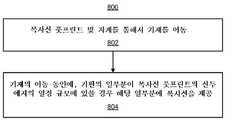
본 발명은 자성-배향 가능한 박편을 배향하는 방법으로서, 자계를 통해서 공급 방향을 따라서 기재(substrate, 116)를 이동시키는 단계로서, 상기 기재(116)는 자성-배향 가능한 박편(magnetically-orientable flake)을 함유하는 유체 캐리어(fluid carrier, 118)를 포함하고, 상기 자계는 상기 자성-배향 가능한 박편을 다수의 배향 중 하나로 배향시키는, 상기 기재(116)를 이동시키는 단계; 및 상기 자계를 통한 상기 기재(116)의 이동 동안에, 마스크(122)의 적어도 하나의 쐐기-형상 개구를 통해서 상기 유체 캐리어(118)의 복수의 선택된 부분 상에 복사선(radiation, 208)을 인가하여, 배향된 상기 박편을 상기 공급 방향에 수직인 방향을 따라서 서로에 대하여 나선형 또는 이중-나선형 배열로 경화시키는 단계를 포함하는, 방법을 제공한다.
본 발명에서, 상기 복수의 선택된 부분은 제1 선택된 부분과 제2 선택된 부분을 포함하고, 상기 유체 캐리어(118)의 복수의 선택된 부분 상에 복사선(208)을 인가하는 것은 복사선(208)을 인가하여 상기 제1 선택된 부분 내의 상기 자성-배향 가능한 박편을 제1 배향에서 고정시키고 상기 제2 선택된 부분 내의 상기 자성-배향 가능한 박편을 상기 제1 배향과는 상이한 제2 배향에서 고정시키는 것을 더 포함할 수 있다.
본 발명에서, 상기 복사선(208)을 인가하는 것은 복사선(208)을 인가하여 다른 부분에서 자성-배향 가능한 박편의 배향각과는 상이하고 또한 상기 공급 방향을 따라서 연장되고 상기 기재(116)의 표면에 대해서 정접하는 평면에 관하여 교차각과는 상이한 각각의 배향각에서 상기 복수의 선택된 부분에 상기 자성-배향 가능한 박편을 고정시키는 것을 더 포함할 수 있다.
본 발명에서, 상기 자계는 상기 자성-배향 가능한 박편이 상기 자계와 정렬되도록 영향을 미치고, 상기 복수의 선택된 부분 상에 복사선(208)을 인가하는 것은 상기 복수의 선택된 부분 내의 상기 자성-배향 가능한 박편이 상기 자계의 각각의 벡터힘과 정렬될 경우 상기 복수의 선택된 부분 상에 복사선(208)을 인가하는 것을 더 포함할 수 있다.
본 발명에서, 상기 기재(116)를 이동시키는 단계는 적어도 0.3 미터/분(1 ft/분)의 속도로 상기 기재(116)를 이동시키는 단계를 더 포함할 수 있다.
본 발명에서, 상기 기재(116)를 이동시키는 단계는 1.5 미터/분(5ft/분) 내지 180 미터/분(600 ft/분)의 속도로 상기 기재(116)를 이동시키는 단계를 더 포함할 수 있다.
본 발명에서, 상기 자계를 통해서 상기 기재(116)를 이동시키기 전에 상기 기재(116) 상에 상기 자성-배향 가능한 박편을 함유하는 유체 캐리어(118)를 도포하는 단계를 더 포함할 수 있다.
본 발명에서, 상기 자계는 적어도 0.001 테슬라의 강도를 가질 수 있다.
본 발명에서, 인가된 복사선(208)은 적어도 하나의 복사선원(radiation source)에 의해 발생되고, 상기 마스크(122)는 상기 적어도 하나의 복사선원에 의해 발생된 복사선의 일부분을 차단시켜, 상기 유체 캐리어(118)의 상이한 위치에 있는 상기 자성-배향 가능한 박편이 각각 상기 기재(116)가 경사짐에 따라서 상기 자성-배향 가능한 박편이 직교-시차 효과(ortho-parallactic effect)를 나타내도록 하는 방식으로 배향되게 할 수 있다.
본 발명에서, 인가된 복사선(208)은 적어도 하나의 복사선원에 의해 발생되고, 상기 마스크(122)는 상기 적어도 하나의 복사선원에 의해 발생된 복사선(208)의 일부분을 차단시켜, 상기 유체 캐리어(118)의 상이한 위치에 있는 상기 자성-배향 가능한 박편이 상이한 크기 중 하나의 크기를 가져서 상기 자성-배향 가능한 박편이 다수의 크기의 합성 이미지를 나타내게 할 수 있다.
본 발명에서, 상기 기재(116) 상에 문자를 인쇄하는 단계를 더 포함하되, 상기 문자는 상기 다수의 크기 중 각각의 크기를 갖는 상기 자성-배향 가능한 박편과 정렬되도록 위치결정될 수 있다.
다른 측면에 따르면, 본 발명은 자성-배향 가능한 박편을 배향하는 방법으로서, 마스크(122)의 쐐기-형상 개구를 통해 복사선(208)을 제공하는 복사선원 및 자계에 의해 제1 방향으로 기재(116)를 이동시키는 단계로서, 상기 자계는 적어도 0.001 테슬라의 강도를 갖고, 자성-배향 가능한 박편을 갖는 잉크가 상기 기재(116) 상에 배치되고 상기 복사선(208)은 선두 에지를 갖는, 상기 기재(116)를 이동시키는 단계; 및 상기 자계를 통한 상기 기재(116)의 이동 동안에, 상기 기재(116)의 일부분이 상기 선두 에지의 상기 제1 방향에 있을 때 상기 기재(116)의 상기 일부분에 복사선(208)을 제공하여, 상기 자성-배향 가능한 박편을 상기 제1 방향에 수직인 방향을 따라서 서로에 대하여 나선형 또는 이중-나선형 배열로 경화시키는 단계를 포함하는, 방법을 제공한다.
본 발명에서, 상기 선두 에지는 상기 제1 방향에서 변화될 수 있다.
본 발명에서, 상기 자계는 적어도 하나의 자석에 의해 발생되고, 상기 복사선(208)은 상기 적어도 하나의 자석에 대해서 고정식일 수 있다.
본 발명에서, 상기 선두 에지는 상기 제1 방향으로 적어도 2㎜ 규모를 갖는 연속 에지를 포함하고, 상기 연속 에지는 상기 제1 방향에 대해서 법선 방향으로 적어도 2 ㎜ 규모를 가질 수 있다.
또 다른 측면에 따르면, 본 발명은 자성-배향 가능한 박편을 배향하는 방법으로서, 쐐기-형상 개구를 갖는 마스크(122)로부터의 복사선 풋프린트(radiation footprint) 및 외부 자기 유도에 대해서 유체 캐리어(118)가 상부에 침착된 기재(116)를 이동시키는 단계로서, 상기 유체 캐리어(118)는 자성-배향 가능한 박편을 포함하고, 상기 복사선 풋프린트는 공급 방향으로 0-이외 규모(non-zero extent)를 갖는 선두 에지를 갖는, 상기 기재(116)를 이동시키는 단계; 및 상기 자성-배향 가능한 박편을 상기 공급 방향에 수직인 방향을 따라서 서로에 대하여 나선형 또는 이중-나선형 배열로 경화시키는 단계를 포함하되; 상기 선두 에지의 적어도 부분에 대해서, 상기 외부 자기 유도는 평면 상에 직교 투영(orthogonal projection)을 지니고, 상기 평면은 상기 기재(116)에 대해서 법선 방향이고 기재 속도 벡터를 포함하며, 상기 직교 투영은 적어도 0.01 라디안만큼 방향이 변화되고 적어도 0.001 테슬라의 강도를 갖는, 방법을 제공한다.
본 발명에서, 상기 선두 에지는 상기 공급 방향으로 적어도 2㎜의 규모를 가질 수 있다.
본 발명에서, 상기 복사선 풋프린트는 상기 외부 자기 유도에 대해서 고정식일 수 있다.
본 발명에서, 경화 복사선은 적어도 하나의 복사선원에 의해 발생되고, 상기 마스크(122)는 상기 적어도 하나의 복사선원에 의해 발생된 복사선(208)의 일부분을 차단시켜, 상기 유체 캐리어(118)의 상이한 위치에 있는 상기 자성-배향 가능한 박편이 각각 상기 기재(116)가 경사짐에 따라서 상기 자성-배향 가능한 박편이 직교-시차 효과를 나타내도록 하는 방식으로 배향되게 할 수 있다.
본 발명에서, 상기 기재(116)를 이동시키는 단계는 적어도 0.3 미터/분(1 ft/분)의 속도로 상기 기재(116)를 이동시키는 단계를 더 포함할 수 있다.The present invention is a method of orienting magnetically-orientable flakes, as the step of moving a
In the present invention, the plurality of selected portions include a first selected portion and a second selected portion, and applying the
In the present invention, the application of the
In the present invention, the magnetic field affects the magnetically-orientable flakes to be aligned with the magnetic field, and applying the
In the present invention, the step of moving the
In the present invention, the step of moving the
In the present invention, it may further include applying a
In the present invention, the magnetic field may have a strength of at least 0.001 Tesla.
In the present invention, the
In the present invention, the
In the present invention, further comprising the step of printing a character on the
According to another aspect, the present invention is a method of orienting magnetically-orientable flakes, wherein a
In the present invention, the leading edge may be changed in the first direction.
In the present invention, the magnetic field is generated by at least one magnet, and the
In the present invention, the leading edge may include a continuous edge having a scale of at least 2 mm in the first direction, and the continuous edge may have a scale of at least 2 mm in a direction normal to the first direction.
According to another aspect, the present invention is a method of orienting magnetically-oriented flakes, comprising: a radiation footprint from a
In the present invention, the leading edge may have a scale of at least 2 mm in the supply direction.
In the present invention, the radiation footprint may be fixed for the external magnetic induction.
In the present invention, hardened radiation is generated by at least one radiation source, and the
In the present invention, the step of moving the
본 개시내용의 특징은, 예로써 예시되고, 동일한 숫자가 동일한 요소를 나타내는 이하의 도면(들)으로 제한되지 않으며, 도면에서:
도 1A 내지 도 1E는, 각각, 본 개시내용의 실시예에 따른, 자성-배향 가능한 박편(magnetically-orientable flake)을 배향시키기 위한 몇 가지 장치를 개략적으로 도시한 도면;
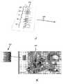
도 2A는, 본 개시내용의 실시예에 따른, 자성-배향 가능한 박편을 배향시키기 위한 장치의 간략화된 등각도(isometric view);
도 2B는, 본 개시내용의 실시예에 따른, 자석 및 이의 자계의 간략화된 등각도;
도 2C는, 본 개시내용의 다른 실시예에 따른, 자성-배향 가능한 박편을 배향시키기 위한 장치의 간략화된 평면도;
도 3A 내지 도 3E는, 각각, 본 개시내용의 실시예에 따른, 자성-배향 가능한 박편이 배향되어 있는 유체 캐리어의 영역의 도면;
도 4A 내지 도 4F는, 각각, 본 개시내용의 실시예에 따른, 도 1A 내지 도 2B 중 어느 하나에 묘사된 장치에서 구현될 수 있는 마스크의 예를 도시한 도면;
도 4G는, 본 개시내용의 실시예에 따른, 평면이 기재에 대해서 법선 방향이고 기재의 속도 벡터를 포함하는 당해 평면 상에의 외부 자기 유도의 직교 투영(orthogonal projection)을 예시하는 도면;
도 4H 내지 도 4Q는, 각각, 본 개시내용의 실시예에 따른, 마스크, 보안 요소 및 유가 물품(article of value)을 도시한 도면;
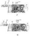
도 5A는, 본 개시내용의 다른 실시예에 따른, 자성-배향 가능한 박편을 배향시키기 위한 장치의 간략화된 평면도;
도 5B는, 본 개시내용의 실시예에 따른, 도 5A에 묘사된 유체 캐리어의 영역에 함유된 자성-배향 가능한 박편의 간략화된 등각도;
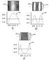
도 5C 내지 도 5F는, 각각, 본 개시내용의 실시예에 따른, 상이한 경사각에서의 광학 요소의 다이어그램 및 그래프;
도 6A는, 본 개시내용의 다른 실시예에 따른, 자성-배향 가능한 박편을 배향시키기 위한 장치의 간략화된 평면도;
도 6B는, 본 개시내용의 실시예에 따른, 도 6A에 묘사된 유체 캐리어의 영역에 함유된 자성-배향 가능한 박편의 간략화된 등각도;
도 6C 내지 도 6E는, 각각, 본 개시내용의 실시예에 따른, 상이한 경사각에서의 광학 요소의 다이어그램 및 그래프; 및
도 7 내지 도 10은, 각각, 본 개시내용의 실시예에 따른, 자성-배향 가능한 박편을 배향시키기 위한 방법의 흐름도.Features of the present disclosure are illustrated by way of example and are not limited to the following drawing(s) in which the same number represents the same element, in the drawings:
1A-1E schematically depict several devices for orienting magnetically-orientable flakes, respectively, according to embodiments of the present disclosure;
2A is a simplified isometric view of an apparatus for orienting magnetically-orientable flakes, in accordance with an embodiment of the present disclosure;
2B is a simplified isometric view of a magnet and its magnetic field, in accordance with an embodiment of the present disclosure;
2C is a simplified plan view of an apparatus for orienting magnetically-orientable flakes, according to another embodiment of the present disclosure;
3A-3E are views, respectively, of a region of a fluid carrier in which a magneto-orientable flake is oriented, according to an embodiment of the present disclosure;
4A-4F illustrate examples of masks that may be implemented in the apparatus depicted in any one of FIGS. 1A-2B, respectively, in accordance with an embodiment of the present disclosure;
4G is a diagram illustrating an orthogonal projection of external magnetic induction onto a plane in which the plane is in a direction normal to the substrate and includes the velocity vector of the substrate, according to an embodiment of the present disclosure;
4H-4Q illustrate a mask, a security element and an article of value, respectively, in accordance with an embodiment of the present disclosure;
5A is a simplified plan view of an apparatus for orienting magnetically-orientable flakes, according to another embodiment of the present disclosure;
5B is a simplified isometric view of a magneto-orientable flake contained in a region of the fluid carrier depicted in FIG. 5A, in accordance with an embodiment of the present disclosure;
5C-5F are diagrams and graphs of optical elements at different tilt angles, respectively, according to an embodiment of the present disclosure;
6A is a simplified plan view of an apparatus for orienting magnetically-orientable flakes, according to another embodiment of the present disclosure;
6B is a simplified isometric view of a magneto-orientable flake contained in a region of the fluid carrier depicted in FIG. 6A, in accordance with an embodiment of the present disclosure;
6C-6E are diagrams and graphs of optical elements at different tilt angles, respectively, according to an embodiment of the present disclosure; And
7-10 are flow charts of a method for orienting magnetically-orientable flakes, respectively, in accordance with an embodiment of the present disclosure.
간략화 및 예시의 목적을 위하여, 본 개시내용은 이의 예를 주로 참조하여 설명된다. 이하의 설명에서, 다수의 특정 상세가 본 개시내용의 철저한 이해를 제공하기 위하여 제시된다. 그러나, 본 개시내용은 이들 특정 상세로 제한하는 일 없이 실시될 수 있음이 용이하게 명백해질 것이다. 다른 경우에, 몇몇 방법 및 구조는 본 개시내용을 불필요하게 애매하게 하지 않도록 상세하게 설명되지 않았다. 본 명세서에서 사용되는 바와 같이, 단수 표현의 용어는 특정 요소 중 적어도 하나를 지칭하는데 사용되고, 용어 "포함한다"는 포함하지만 이것으로 제한되는 것은 아님을 의미하며, 용어 "포함하는"은 포함하지만 이것으로 제한되는 것은 아님을 의미하고, 용어 "에 기초한"은 적어도 부분적으로 기초하는 것을 의미한다. 본 명세서에서 사용되는 바와 같이, 용어 "실질적으로", "대략" 및 "약"은 기재된 값의 +/- 5% 이내의 값의 범위를 나타낸다.For purposes of simplicity and illustration, the present disclosure has been described primarily with reference to examples thereof. In the following description, a number of specific details are set forth to provide a thorough understanding of the present disclosure. However, it will be readily apparent that the present disclosure may be practiced without limiting to these specific details. In other instances, some methods and structures have not been described in detail so as not to unnecessarily obscure the present disclosure. As used herein, the term in the singular expression is used to refer to at least one of a particular element, the term “comprising” means including but not limited to, and the term “comprising” includes but is not limited to It is meant not to be limited to, and the term "based on" means based at least in part. As used herein, the terms “substantially”, “approximately” and “about” refer to a range of values within +/- 5% of the stated value.
첨부 도면에 도시된 요소들은 부가적인 구성요소를 포함할 수 있고 이들 도면에 기재된 구성요소의 일부는 본 개시내용의 범위로부터 벗어나는 일 없이 제거 및/또는 변형될 수 있음에 유의해야 한다. 또한, 도면에 묘사된 요소들은 일정 척도로 그려지지 않을 수도 있고, 따라서, 이들 요소는 도면에 도시된 것과는 상이한 크기 및/또는 구성을 가질 수도 있다.It should be noted that elements shown in the accompanying drawings may include additional elements, and some of the elements described in these drawings may be removed and/or modified without departing from the scope of the present disclosure. In addition, elements depicted in the drawings may not be drawn to scale, and thus, these elements may have a different size and/or configuration than those depicted in the drawings.
유체 캐리어 내에 자성-배향 가능한 박편을 배향시키기 위한 장치 및 방법이 본 명세서에 개시된다. 특히, 본 명세서에 개시된 장치 및 방법은, 유체 캐리어 내에 분산된 자성-배향 가능한 박편이 운동학적 광학 효과가 얻어질 수 있도록, 예컨대, 자성-배향 가능한 박편으로부터 반사된 광의 밴드(band) 또는 다수의 밴드가 유체 캐리어를 함유하는 광학 요소가 경사지는 방향에 수직인 방향으로 이동하도록 하는 방식으로 배향될 수 있게 한다. 하나의 관점에서, 자성-배향 가능한 박편은 하나 이상의 자계선이 유체 캐리어가 공급될 때 기재의 방향과 동일 선상으로 연장되는 자계에 자성-배향 가능한 박편을 적용시킴으로써 이와 같이 해서 배향될 수 있다. 또한, 자성-배향 가능한 박편은 적어도 하나의 개구를 포함하는 마스크의 사용을 통해서 목적하는 배향으로 고정될 수 있고, 여기서 마스크와 적어도 하나의 개구는, 자성-배향 가능한 박편이 기재를 투과하는 자계선과 정렬될 경우 자성-배향 가능한 박편이 방사선원 또는 복사선원(radiation source)에 의해 기재에 관하여 목적하는 이면각(dihedral angle)에서 고정되도록 자계에 관하여 전략적으로 위치결정될 수 있다. 게다가, 자성-배향 가능한 박편을 갖는 유체 캐리어의 다수의 층이 제공될 수 있고 각종 광학 효과를 갖는 이미지를 생성하도록 경화될 수 있다.An apparatus and method for orienting magnetically-orientable flakes within a fluid carrier are disclosed herein. In particular, the apparatus and methods disclosed herein allow a magnetically-orientable flake dispersed in a fluid carrier to obtain a kinematic optical effect, e.g., a band or a plurality of bands of light reflected from the magnetically-orientable flake. It allows the band to be oriented in such a way that it moves in a direction perpendicular to the direction in which the optical element containing the fluid carrier is tilted. In one aspect, a magneto-orientable flake can be oriented in this way by applying a magneto-orientable flake to a magnetic field that extends in line with the direction of the substrate when one or more lines of magnetic field are supplied with a fluid carrier. Further, the magneto-orientable flake can be fixed in a desired orientation through the use of a mask comprising at least one opening, wherein the mask and at least one opening are provided with a magnetic field line through which the magneto-orientable flake passes through the substrate. When aligned, the magneto-orientable flakes can be strategically positioned with respect to the magnetic field such that they are fixed at a desired dihedral angle with respect to the substrate by means of a radiation source or a radiation source. In addition, multiple layers of fluid carriers with magnetically-orientable flakes can be provided and cured to produce images with various optical effects.
본 명세서에 개시된 마스크의 적어도 하나의 개구는 임의의 형상, 크기일 수 있거나, 또는 임의의 배향을 가질 수 있다. 몇몇 예에서, 적어도 하나의 개구(예컨대, 도 2A에 도시된 마스크의 개구(124))는 마스크에 의해 모든 측면 상에서 둘러싸여 있을 수 있다. 다른 예에서, 적어도 하나의 개구(예컨대, 도 4A, 도 4B 및 도 4D의 개구(402))는 적어도 하나의 개방 측면을 가질 수 있다. 몇몇 예에서, 적어도 하나의 개구는 하나 이상의 직선 측면을 가질 수 있다. 부가적으로 또는 대안적으로, 적어도 하나의 개구는 하나 이상의 만곡된 측면을 가질 수 있다.At least one opening of the mask disclosed herein can be of any shape, size, or can have any orientation. In some examples, at least one opening (eg, opening 124 of the mask shown in FIG. 2A) may be surrounded on all sides by the mask. In another example, at least one opening (eg, opening 402 in FIGS. 4A, 4B and 4D) may have at least one open side. In some examples, at least one opening can have one or more straight sides. Additionally or alternatively, at least one opening may have one or more curved sides.
본 명세서에 개시된 장치 및 방법은 또한 기재가 자계를 통해서 연속해서 공급되는 동안 자성-배향 가능한 박편이 고정되도록 할 수 있다. 이와 관련하여, 본 명세서에 개시된 장치 및 방법은 자성-배향 가능한 박편을 고속 방식으로 인쇄 및 배향시키도록 구현될 수 있다. 나아가, 본 명세서에 개시된 장치 및 방법은 광학 요소를 가로질러 광 밴드의 고도로 현저한 이동을 발생하도록 구현될 수 있다. 광학 요소는, 예를 들어, 지폐, 통화, 주권(stock certificate) 등과 같은 금융관련 서류, 또는 소프트웨어 문서, 보안 씰(security seal), 및 인증 및/또는 위조방지 디바이스로서의 유사한 대상체 상에 제공될 수 있다.The apparatus and methods disclosed herein may also allow magnetically-orientable flakes to be fixed while the substrate is continuously fed through a magnetic field. In this regard, the apparatus and methods disclosed herein can be implemented to print and orient magnetically-orientable flakes in a high-speed manner. Furthermore, the apparatus and methods disclosed herein can be implemented to generate a highly significant movement of the optical band across the optical element. The optical elements may be provided on financial documents, such as, for example, banknotes, currencies, stock certificates, etc., or on similar objects as software documents, security seals, and authentication and/or anti-counterfeiting devices. have.
본 명세서에서 논의된 바와 같은 유체 캐리어 중의 자성-배향 가능한 박편의 분산물은 대안적으로 액체 코팅 중, 습식 잉크(수계 또는 용매계, 액체 잉크, 페이스트-유사 잉크 등인지의 여부) 중, 미경화 도료(수계인지 용매계인지의 여부) 중, 미경화 유기 결합제 중, 미경화 유기 캐리어 중, 미경화 유기 비히클 중 등의 자성-배향 가능한 박편 또는 자화 가능한 박편의 분산물로서 기술될 수 있다.The dispersion of magnetically-orientable flakes in a fluid carrier as discussed herein can alternatively be uncured, in liquid coating, in wet ink (whether water-based or solvent-based, liquid ink, paste-like ink, etc.). It can be described as a dispersion of magnetically-orientable flakes or magnetizable flakes, such as in a paint (whether water-based or solvent-based), in an uncured organic binder, in an uncured organic carrier, in an uncured organic vehicle.
공급원이 동일한 하나 이상의 자성-배향 가능한 박편에 대해서 외부에 있는 자계의 인가를 통한 하나 이상의 자성-배향 가능한 박편의 위치 및 정렬을 변화시키는 현상은 많은 방식으로 기술될 수 있음이 이해되어야 한다. 본 개시내용은 자계의 방향에서 자성-배향 가능한 박편의 정렬/배향을 기술한다. 자성-배향 가능한 박편의 정렬/배향은 부가적으로 또는 대안적으로 자계의 방향으로 기술될 수 있다(자계의 방향은 공간 내 임의의 점에서 자계선에 정접하는 것으로 정의될 수 있다). 다른 예에서, 자성-배향 가능한 박편의 정렬/배향은 외부 자기 벡터힘에 의해 기술될 수 있다.It should be understood that the phenomenon of changing the position and alignment of one or more magneto-orientable flakes through the application of an external magnetic field to one or more magneto-orientable flakes of the same source can be described in many ways. The present disclosure describes the alignment/orientation of magnetically-orientable flakes in the direction of the magnetic field. The alignment/orientation of magnetically-orientable flakes can additionally or alternatively be described in the direction of the magnetic field (the direction of the magnetic field can be defined as tangent to the magnetic field line at any point in space). In another example, the alignment/orientation of a magneto-orientable flake can be described by an external magnetic vector force.
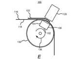
도 1A는 본 개시내용의 일례에 따른, 자성-배향 가능한 박편을 배향시키기 위한 장치(100)의 개략도를 도시한다. 도시된 바와 같이, 장치(100)는 제1 극(104) 및 제2 극(106)을 가진 자석(102)을 포함할 수 있다. 제1 극(104)은 제1 극성을 가질 수 있고 제2 극(106)은 반대의 제2 극성을 가질 수 있다. 예를 들어, 제1 극(104)은 자석(102)의 남극일 수 있고 제2 극(106)은 자석(102)의 북극일 수 있다. 다른 예에서, 제1 극(104)은 북극일 수 있고 제2 극(106)은 남극일 수 있다. 본 명세서에서 이하에서 더 상세히 논의되는 바와 같이, 자석(102)의 반대 극은 자석(102)으로부터 나오는 자계선을 갖는 자계를 인가할 수 있다. "자기 유도"라고도 지칭될 수 있는 자기 벡터힘은 자석(102)으로부터 나오는 각종 방향에서 자계에 의해 인가될 수 있는 힘으로서 정의될 수 있다. 예를 들어, 자석(102)의 극 중 하나는 기재의 하부 표면, 예컨대, 유체 캐리어를 함유하는 표면과는 반대쪽의 기재의 표면과 대면할 수 있다.1A shows a schematic diagram of an
장치(100)는 또한 공급 방향(114)으로 기재(116)를 공급하도록 배열된 1쌍의 롤러의 형태로 공급 기구(110)를 포함하는 것으로 도시되어 있다. 기재(116)는 롤러에 의해 직접 공급되고 있는 것으로 도시되어 있지만, 기재(116)는 대신에 지지부(도시 생략) 상에 지지될 수도 있다. 다른 종류의 공급 기구가 장치(100)의 범위 내에서 가능하다. 지지부는, 사용된 경우, 벨트, 플랫폼, 한 줄 이상의 파지부(gripper), 프레임 등일 수 있고, 기재(116)가 지지부와 함께 공급 방향(114)으로 이동될 수 있도록 기재(116)를 지지할 수 있다. 각종 예에서, 장치(100)는 공급 기구(110)의 상류 및/또는 하류에 공급된 추가의 공급 기구(도시 생략)를 포함할 수 있다.The
기재(116)는 종이, 플라스틱 필름, 적층체, 명함 재료(card stock) 등으로 형성될 수 있다. 특정 예에서, 기재(116)는 통화로 절단될 수 있는 지폐이다. 기재(116)는 또한 연속 롤 또는 일련의 기재 시트일 수 있거나, 또는 임의의 분리식 또는 연속식 형상일 수 있다. 또한, 기재(116)의 상부 표면의 적어도 일부는 자성-배향 가능한 입자 또는 박편이 분산된 유체 캐리어(118)로 코팅될 수 있다. 유체 캐리어(118)는 또한 잉크, 습식 잉크, 코팅, 유체 코팅 등으로 지칭될 수 있다. 유체 캐리어(118)는 그라비아, 잉크-젯 인쇄, 플렉소인쇄, 요판 인쇄, 실크 스크인 인쇄, 도장 등과 같은 인쇄 기술을 통해서 도포될 수 있다. 유체 캐리어(118)는 잉크 또는 도료의 형태일 수 있고 적어도 미리 결정된 시간 길이 동안 또는 충분한 양의 에너지가 유체 캐리어(118)에 인가될 때까지 유체 형태로 유지될 수 있다. 예를 들어, 유체 캐리어(118)는 액체 또는 페이스트-유사 캐리어일 수 있고, 자외(UV)광, 전자빔, 열, 레이저 등의 형태로 에너지의 입수를 통해서 경화 가능할 수 있다. 특정 예에 의하면, 유체 캐리어(118)는 광중합체, 용매계 캐리어, 수계 캐리어 등일 수 있다. 또한, 유체 캐리어(118)는 투명하거나, 맑거나, 무색이거나 또는 엷은 색조일 수 있다.The
실시예에 따르면, 자성-배향 가능한 박편을 갖는 유체 캐리어(118)는, 유체 캐리어(118)가 자석(102) 위로 이동함에 따라서 유체 캐리어(118)가 유체 상태인 채로 있도록 기재(116)가 자석(102) 위에 공급되기 직전에 기재(116) 상에 도포될 수 있다. 이 예에서, 장치(100)의 공급 기구(110) 또는 다른 기구(도시 생략), 예컨대, 인쇄 기구는 기재(116)가 공급 방향(114)으로 공급됨에 따라서 기재(116) 상에 자성-배향 가능한 박편을 갖는 유체 캐리어(118)를 도포할 수 있다. 자성-배향 가능한 박편은 유체 캐리어(118)가 기재(116) 상에 도포되기 전에 또는 후에 유체 캐리어(118)에 혼합될 수 있다. 실시예에 따르면, 자성-배향 가능한 박편은 비구체 및 평면 박편, 예컨대, 자계를 이용해서 정렬될 수 있는 안료 박편이며, 반사성일 수고 있고/있거나, 색 변환될 수 있고, 예컨대, 자성-배향 가능한 박편은 하나의 관찰각에서 하나의 색 그리고 다른 관찰각에서 다른 색을 갖는 것으로 보일 수 있다. 자성-배향 가능한 박편은 나머지 자화를 유지할 수 있거나 유지하지 못할 수도 있다. 예로서, 자성-배향 가능한 박편은 약 1 내지 약 500 마이크로미터에 걸쳐 어느 것인가 그리고 약 0.1 내지 약 100 마이크로미터 두께의 어느 것인가일 수 있다. 또한, 자성-배향 가능한 박편은 알루미늄, 금, 니켈, 백금, 금속 합금 등의 박막과 같은 금속층일 수 있거나, 또는 니켈, 철, 또는 합금 박편과 같은 금속 박편일 수 있다. 부가적으로 또는 다른 예에서, 자성-배향 가능한 박편은 엷은 색조의 층으로 코팅될 수 있거나, 또는 흡수체-스페이서-반사체 파브리-페로형(Fabry-Perot type) 구조체와 같은 광 간섭 구조체를 포함할 수 있다.According to an embodiment, the
자성-배향 가능한 박편의 평면에 대해서 법선 방향에서 본 자성-배향 가능한 박편은 밝게 보일 수 있는 한편, 평면의 에지를 따라서 본 자성-배향 가능한 박편은 어둡게 보일 수 있다. 예를 들어, 조명원(도시 생략)으로부터의 광은 자성-배향 가능한 박편이 관찰자에 대해서 법선 위치에 있을 때 관찰자에 대해서 자성-배향 가능한 박편으로부터 반사될 수 있다. 그러나, 자성-배향 가능한 박편이 관찰자에 대해서 법선 방향의 평면에 관하여 경사진 경우, 자성-배향 가능한 박편은 에지 상에서 보일 수 있고, 이에 따라서 어둡게 보일 수 있다. 마찬가지로, 자성-배향 가능한 박편이 색-변환형이면, 자성-배향 가능한 박편은 법선 평면을 따라 볼 때 하나의 색으로, 그리고 경사진 평면을 따라 볼 때 다른 색으로 보일 수 있다. 적어도 하나의 자석의 자계의 방향과 정렬되게 하는 자성-배향 가능한 박편을 본 명세서에서 특히 언급하였지만, 경우에 따라서, 자성-배향 가능한 박편의 전부는 아니더라도 목적하는 광학 효과를 여전히 내면서 자계의 방향과 정렬될 수 있음이 이해되어야 한다.Magneto-orientable flakes viewed from the direction normal to the plane of the magneto-orientable flake may appear bright, while magneto-orientable flakes viewed along the edge of the plane may appear dark. For example, light from an illumination source (not shown) may be reflected from the magneto-orientable flake with respect to the observer when the magneto-orientable flake is in a position normal to the observer. However, if the magneto-orientable flake is inclined with respect to the plane in the direction normal to the observer, the magneto-orientable flake may be visible on the edge and thus appear dark. Likewise, if the magneto-orientable flakes are color-converting, the magneto-orientable flakes may appear as one color when viewed along a normal plane and a different color when viewed along an inclined plane. Although magneto-orientable flakes that are aligned with the direction of the magnetic field of at least one magnet are specifically mentioned in this specification, in some cases, if not all of the magneto-orientable flakes are aligned with the direction of the magnetic field while still producing the desired optical effect. It should be understood that it can be.
실시예에 따르면, 기재(116)는 유체 캐리어(118)가 경화되거나 건조되어 자성-배향 가능한 박편이 자계의 방향으로 배향될 수 있게 되기 전에 자석(102)의 자계를 통해서 이동될 수 있다. 즉, 공급 기구(110)는 유체 캐리어(118) 중의 자성-배향 가능한 박편이 자석(102)의 제1 극(104) 및 제2 극(106)에 의해 인가된 자계를 통해서 공급되도록 공급 방향(114)을 따라 기재(116)를 공급할 수 있다. 자계는 자석의 극으로부터 나오는 자계의 선(자속 밀도)을 갖는 것으로 묘사될 수 있다. 대안적으로, 본 명세서에서 이하에서 더 상세히 논의되는 바와 같이, 자계는 벡터힘으로 구성되는 것으로 기술될 수 있고, 자성-배향 가능한 박편은 벡터힘과 밀접하게 정렬될 수 있다. 또한, 벡터힘이 자석(102)을 가로질러 균일하지 않으므로, 자성-배향 가능한 박편의 배향은 제1 극(104) 및 제2 극(106)에 관하여 자성-배향 가능한 박편의 위치에 따라서 변화될 수 있다. 이와 같이 해서, 자성-배향 가능한 박편의 배향은 기재(116)가 제1 극(104) 및 제2 극(106)에 의해 인가된 자계를 통해서 공급됨에 따라서 변화될 수 있다. 즉, 자성-배향 가능한 박편의 이면각은 기재(116)의 평면에 관하여 변화될 수 있다. 이면각은 우측각에서 교차선을 절단하는 제3 평면에서 2개의 평면 사이의 각으로서 정의될 수 있다.According to an embodiment, the
또한 도 1A에 도시된 바와 같이, 장치(100)는 복사선원(120)(또는 복사선원(120)의 어레이)을 포함할 수 있고, 이 복사선원은 기재(116)가 공급 방향(114)으로 공급됨에 따라서 유체 캐리어(118) 상에 복사선(혹은 방사선)을 인가하여 유체 캐리어(118)를 경화시키거나 또는 다르게는 고형화시킬 수 있다. 복사선원(120)은 자외(UV)광, 전자빔, 열, 레이저 등의 형태로 복사선을 인가할 수 있다. 적어도 하나의 개구(124)를 갖는 마스크(122)는 또한 기재(116)가 복사선원(120)에 의해 통과됨에 따라서 유체 캐리어(118)의 어느 부분 또는 부분들이 복사선원(120)으로부터 복사선을 수광하는 것을 제어하도록 복사선원(120)과 유체 캐리어(118) 사이에 위치결정되는 것으로 묘사된다. 복사선이 적어도 하나의 개구를 통해서 기재(116)에 입사되는 위치는 복사선 풋프린트(radiation footprint)인 것으로 고려될 수 있다. 마스크(122)는 약 0.25㎜ 내지 2.5㎜(0.01" 내지 약 0.1")의 범위 내의 두께를 가질 수 있다. 실시예에 따르면, 적어도 하나의 개구(124)는 다른 자성-배향 가능한 박편이 다른 배향에서 적어도 부분적으로 고정되는 것을 방지하면서 자성-배향 가능한 박편이 미리 결정된 배향에서 적어도 부분적으로 고정되도록 자석(102) 및 복사선원(126)에 관하여 전략적으로 위치결정된다. 본 명세서에서 이하에서 더 상세히 논의되는 바와 같이, 개구 또는 개구들(124)은, 기재(116)의 평면 내에 실질적으로 놓여 있고 공급 방향(114)에 대해서 수직(또는 동등, 직교 또는 횡방향)인 방향을 따라서 서로에 관하여 나선형 또는 이중-나선형 배열이 되게끔 자성-배향 가능한 박편을 적어도 부분적으로 고정시키도록 위치결정될 수 있다.Also, as shown in FIG. 1A, the
또한, 도 1A에 자외(UV)광, 전자빔, 열 등의 형태로 유체 캐리어(118) 상에 에너지를 또한 인가할 수 있는 제2 복사선원(126)이 도시되어 있다. 제2 복사선원(126)은 복사선원(120)과 비교해서 동일한 유형의 에너지 또는 상이한 유형의 에너지를 인가할 수 있다. 임의의 관점에서, 제2 복사선원(126)은 선택적일 수 있고, 만약 존재한다면, 유체 캐리어(118)를 더욱 고형화시키도록 구현될 수 있다.Also shown in FIG. 1A is a
이제 도 1로 되돌아가면, 본 개시내용의 다른 실시예에 따른, 자성-배향 가능한 박편을 배향시키기 위한 장치(100)의 개략도가 도시되어 있다. 도 1B에 도시된 장치(100)는 도 1A와 관련하여 위에서 기재된 것과 동일한 특징부의 다수를 포함하며, 따라서, 이들 공통 특징부는 도 1B와 관련하여 상세히 기재되지 않을 것이다. 그러나, 도 1B에 도시된 장치(100)는, 장치(100)가 공급 방향(114)을 따라서 제1 자석(102)과 차례로 위치결정된 제2 자석(103)을 포함한다는 점에서 도 1A에 도시된 장치(100)와는 상이하다. 또한, 제2 자석(103)은 제2 극(106)이 제2 자석(103)의 제1 극(104)보다 기재(116)에 더 가깝게 위치결정되도록 제1 자석(102)에 관하여 회전되는 것처럼 도시되어 있다. 이 관점에서, 자석(102 및 103)의 반대 극은 기재(116)에 더 가깝다. 그와 같이, 자석(102 및 103)은 도 1A에 도시된 단일의 자석(102)에 의해 발생된 자계와 유사한 자계를 발생할 수 있다.Turning now to FIG. 1, a schematic diagram of an
다른 예에서, 장치(100)는 자성-배향 가능한 박편이 목적하는 배향으로 정렬되는 결과를 초래하는 자계를 형성하도록 부가적인 또는 추가의 자석을 포함할 수 있다.In another example, the
장치(100)는 기재(116)가 유체 캐리어(118)를 이동시켜서 자석(102) 또는 자석(102/103) 부근에 위치시키도록 설계될 수 있고, 자석(들)(102/103) 부근에 유체 캐리어(118) 내 자성-배향 가능한 박편이 그 자성-배향 가능한 박편이 경험하는 국부 자기 유도에 따라서 토크를 경험할 것이다. 토크가 충분히 강력하면, 미경화 잉크 중의 자성-배향 가능한 박편은 자성-배향 가능한 박편이 국부 자기 유도와 실질적으로 정렬될 때까지 기재(116) 이동에 대해서 평행한 축을 중심으로 회전할 것이다. 자성-배향 가능한 박편에 의해 경험하는 토크는 그 자성-배향 가능한 박편에서 국부 자기 유도에 좌우되며, 여기서 국부 자기 유도는 모든 외부 자기 유도의 벡터합이다. 실제로, 원치 않는 자화 공급원은 경화가 일어나는 곳으로부터 충분히 고립될 수 없으므로, 이들의 총 국부 자기 유도의 기여는 자석(들)(102/103)에 의해 제공된 자기 유도와 비교할 경우 무시될 수 있다. 예를 들어, 전기 모터로부터 나온 기생 자기 유도가 경화가 일어나기 직전에 자성-배향 가능한 박편의 정렬과 간섭하는 것은 바람직하지 않을 수 있다. 따라서, 자석(들)(102/103)에 의해 제공된 자기 유도는 외부 자기 유도라고 불릴 수 있으며, 외부 자기 유도는 자석(들)(102/103)으로 인한 또는 자성-배향 가능한 박편을 경사지게 하고 배향시킬 목적으로 장치(100)에 의도적으로 위치결정된 1개 이상의 자석으로 인한 자기 유도임이 이해된다. 자석(들)(102/103)은 영구 자석 또는 전자석일 수 있고, 이러한 자석의 조립체를 포함할 수 있다. 따라서, 반드시 특정 자석 또는 자석 조립체를 지칭하는 일 없이 각종 실시형태를 기술할 때 외부 자기 유도를 지칭하는 것이면 충분하다. 또한, 흔히 용어 "외부 자기 유도" 및 "외부 자기 유도 벡터"는 호환 가능하게 사용된다.The
이제 도 1C 내지 도 1E를 참조하면, 본 개시내용의 추가의 실시예에 따른 자성-배향 가능한 박편을 배향시키기 위한 장치(100)의 개략도가 각각 도시되어 있다. 도 1C에 도시된 바와 같이, 기재(116)는 가요성 기재일 수 있고, 반경(132)을 가진 롤러(130)에 의해 지지될 수 있다. 롤러(130)는 비자성 재료, 예를 들어, 플라스틱 재료, 고무 재료, 세라믹 재료 등으로 형성될 수 있다. 자성-배향 가능한 박편을 함유하는 유체 캐리어(118)는 기재(116)의 상부 표면(예컨대, 실질적으로 자석(102 및 103) 및/또는 복사선원(120) 및 실질적으로 반대쪽 롤러(130)와 대면하는 기재의 표면) 상에 제공될 수 있다. 도 1C에 도시된 장치(100)는, 대향하는 극(104 및 106)이 롤러(130)가 화살표(136)로 표시된 방향으로 회전함에 따라서 자계를 형성하되 이 자계를 통해서 기재(116)의 부분이 공급되도록 롤러(130)에 관하여 위치결정된 자석(102 및 103)을 포함할 수 있다. 선(138)으로 표시될 수 있는 자계는, 각각의 방향이 자계의 중간에서 서로 실질적으로 평행한 벡터힘을 포함할 수 있으며, 복사선원(120)은 자석(102)과 (103) 사이의 중심 위치에 가까운 유체 캐리어(118) 상에 에너지를 인가하도록 위치결정될 수 있다. 따라서, 도 1C는 기재(116)가 적어도 거의 선형 자계(낮은 정도의 자계선 곡률)의 북-남 기본 방향을 따라서 즉석으로 이동하는 실시예를 도시한다.Referring now to FIGS. 1C-1E, a schematic diagram of an
도 1A 및 도 1B에 도시된 장치(100)와 유사하게, 도 1C에 도시된 복사선원(120)은 유체 캐리어(118)의 적어도 부분적인 고형화를 초래하도록 유체 캐리어(118) 상에 복사선을 인가할 수 있다. 또한, 적어도 하나의 개구(124)(도시 생략)를 포함하는 마스크(122)는 복사선원(120)과 롤러(130) 사이에 위치결정되어, 유체 캐리어(118) 상에 복사선원(120)으로부터의 복사선의 인가를 선택적으로 차단(예컨대, 복사선 풋프린트를 생성)하고 따라서 자성-배향 가능한 박편이 유체 캐리어(118) 내에 고정될 수 있는 배향을 제어할 수 있다. 실시예에 따르면, 마스크(122)는, 롤러(130)의 반경(132)과 롤러(130)의 중심으로부터의 거리(134) 간의 차이가 약 0.05㎜ 내지 약 6.25㎜(약 0.002 인치 내지 약 0.25 인치)의 범위의 값이 되도록 거리(134)에 위치결정될 수 있다.Similar to the
도 1D는, 자계 발생이 상이한 것을 제외하고 도 1C에 도시된 배열과 유사한 배열을 도시한다. 즉, 도 1C에서 발생된 선형 자계 대신에, 도 1D에서, 발생된 자계가 복사선원(120)이 복사선을 인가하는 기재(116) 상의 위치에서 실질적으로 만곡되어 있다. 도시된 바와 같이, 자석(102)은 복사선원(120)으로부터 도광체(light guide)(142)가 삽입될 수 있는 구멍(140)을 포함할 수 있다. 대안적으로, 그러나, 다수의 자석은 도 1D에 도시된 자계를 발생하도록 위치결정될 수 있다. 구멍(140), 도광체(142) 및/또는 다수의 자석은 도 1A 내지 도 C 및 도 1E의 장치를 포함하지만 이들로 제한되는 것은 아닌 임의의 장치 및/또는 배열과 사용될 수 있음에 유의해야 한다.Fig. 1D shows an arrangement similar to the arrangement shown in Fig. 1C except that the magnetic field generation is different. That is, instead of the linear magnetic field generated in FIG. 1C, in FIG. 1D, the generated magnetic field is substantially curved at a position on the
도 1E는, 자석(102)이 롤러(130) 내에 위치결정된 것을 제외하고 도 1C에 도시된 배열과 유사한 배열을 도시한다. 즉, 도 1E에 도시된 롤러(130)는 중공 실린더일 수 있고, 자석(102)은 롤러(130) 내측에 위치결정될 수 있다. 또한, 자석(102)은, 롤러(130)가 회전됨에 따라서 자석(102)이 이동 또는 회전되지 않도록 고정 방식으로 유지될 수 있다. 즉, 자석(102)은 복사선원(120)과 관련하여 고정된 공간 관계로 유지될 수 있다. 또한, 기재(116)의 부분이 통과하여 이동될 수 있는 자계는 도 1C 및 도 1D에 도시된 자계와는 상이할 수 있다.FIG. 1E shows an arrangement similar to the arrangement shown in FIG. 1C except that the
위에서 논의된 실시예의 각각에 있어서, 기재(116)는 원통형 롤러(130)에 의해 이동되는 것처럼 기술하였다. 다른 예에서, 그러나, 롤러(130) 대신에, 장치(100)는 기재(116)가 슬라이딩 접촉할 수 있는 만곡된 표면을 포함할 수 있다. 부가적으로 또는 대안적으로, 기재(116)는 롤러(130)와 같은 만곡된 표면 상에 지지될 수 있거나, 또는 다른 방식으로 지지될 수 있는 만곡된 형상을 가질 수 있다. 예로써, 기재(116)는 미끄럼 접촉으로 포물선 형상의 만곡 표면으로 지지될 수 있는 만곡된 표면을 가질 수 있다.In each of the embodiments discussed above, the
실시예에 따르면, 도 1A 내지 도 1E에 도시된 장치(100) 중 어느 하나는 다수의 스테이션을 포함할 수 있으며, 여기서 다수의 스테이션의 각각은 자석(102), 마스크(122) 및 복사선원(120)의 각각의 세트를 포함한다. 이들 실시예에서, 스테이션은, 기재(116)가 스테이션의 각각을 통해서 순차로 이동될 수 있도록 배열될 수 있다. 또한, 스테이션의 각각은 유체 캐리어(118)의 추가의 층을 도포하는 각각의 유체 도포 기구를 포함할 수 있다. 이와 같이, 예를 들어, 기재(116)의 표면은 제1 유체 캐리어(118)로 코팅될 수 있고 제1 유체 캐리어(118)는 제1 유체 캐리어(118) 내에 자성-배향 가능한 박편을 배항시키도록 자계 및 복사선에 노출될 수 있다. 제1 유체 캐리어(118)가 경화된 후에, 제2 유체 캐리어(118)가 경화된 제1 유체 캐리어(118) 위에 도포될 수 있다. 제2 유체 캐리어(118)는 또한 제2 유체 캐리어(118) 내에 자성-배향 가능한 박편을 배항시키도록 자계 및 복사선에 노출될 수 있다.According to an embodiment, any one of the
제2 유체 캐리어(118) 내 자성-배향 가능한 박편은 제1 유체 캐리어(118) 내 자성-배향 가능한 박편과 동일한 방식으로 또는 상이한 방식으로 배향될 수 있다. 즉, 예를 들어, 제2 유체 캐리어(118) 내 자성-배향 가능한 박편은 제1 유체 캐리어(118) 내 자성-배향 가능한 박편과 동일한 형태를 가질 수 있거나, 또는 제2 유체 캐리어(118) 내 자성-배향 가능한 박편은 제1 유체 캐리어(118) 내 자성-배향 가능한 박편과는 상이한 형태를 가질 수도 있다. 게다가, 유체 캐리어(118)의 추가의 층 또는 층들이 추가의 스테이션에서 도포되고 경화될 수 있다. 이와 관련하여, 유체 캐리어(118)의 다수의 코팅을 포함하는 물품을 제조하기 위하여 다수의 스테이션이 구현될 수 있다.The magneto-orientable flakes in the
예로써, 제1 유체 캐리어(118)는 하나의 농도(예컨대, 약 15 내지 50 중량%)의 반사 또는 색변환성의 회절 또는 임의의 다른 소판(platelet)-형상 자성 안료와 혼합된 투명한 또는 건조된 잉크 또는 도료 비히클일 수 있다. 제1 유체 캐리어(118)는 기재(116)의 표면 상에 임의의 미리 결정된 그래픽 패턴으로 인쇄/도장되고, 자계에 노출되어 미리 결정된 광학 효과를 형성하고, 경화되어 제1 유체 캐리어(118)의 고형화 후 제1 유체 캐리어(118)의 층 내에 자성-배향 가능한 박편을 고정시킬 수 있다. 제2 유체 캐리어(118)는 비교적 낮은 농도(예컨대, 약 0.1 내지 15 중량%의 범위)일 수 있다. 제2 유체 캐리어(118)용의 잉크 또는 도료 비히클은 투명하거나 건조될 수 있다. 제2 유체 캐리어(118) 내 자성-배향 가능한 박편은 제1 유체 캐리어(118)에 대한 것과 동일할 수 있거나 또는 이들은 상이할 수 있다. 제2 유체 캐리어(118)용의 박편 크기는 또한 제1 유체 캐리어(118)용의 박편 크기와 동일 또는 상이할 수 있다. 게다가, 제2 유체 캐리어(118)용의 박편의 색은 제1 유체 캐리어(118)용의 박편의 색과 동일 또는 상이할 수 있다. 제2 유체 캐리어(118)에 인가된 자계의 형상 및/또는 강도는 제1 유체 캐리어(118)에 인가된 자계의 형상 및/또는 강도와 동일 또는 상이할 수 있다. 부가적으로 또는 다른 예에서, 제2 유체 캐리어(118)에 대한 그래픽 패턴은 제1 유체 캐리어(118)에 대한 그래픽 패턴과 동일 또는 상이할 수 있다. 이와 관련하여, 잉크 또는 안료 색의 조합은 유체 캐리어(118)의 다수의 층으로부터 형성된 이미지에서 특정 색을 증강 또는 저감시킬 수 있다.By way of example, the
실시예에 따르면, 본 명세서에 개시된 바와 같이 기재(116) 상에 유체 캐리어(118)의 다수의 코팅의 도포 및 경화를 통해서, 이미지는 그 이미지 내의 다수의 개별의 특징부가 동시에 이동하는 것처럼 보이도록 자성-배향 가능한 박편으로 형성될 수 있다. 또한, 이동은 이미지 상에 광원이 이동될 경우 또는 이미지가 이동될 경우 상대적인 이동일 수 있다. 부가적으로 또는 다른 예에서, 이미지 내 다수의 개별적인 특징부는, 이미지가 상이한 방향으로 이동될 경우 또는 이미지 상에의 광원이 상이한 방향으로 이동될 경우 하나의 특징부는 정지하는 한편 다른 하나는 이동하거나 또는 그 반대로 되어, 이동하는 것으로 보일 수 있다. 특정 실시예에서, 본 명세서에 개시된 바와 같이 기재(116) 상에 유체 캐리어(118)의 다수의 코팅의 도포 및 경화를 통해서, 광학적-환상 효과가 증대된 선, 점, 원호 및 기타 형상의 복합 패턴은 시각적으로 암호화된 물품이 위조되기 어렵게 만드는 물품 인쇄 공정에서 사용될 수 있다.According to an embodiment, through the application and curing of multiple coatings of the
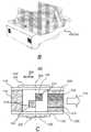
이제 도 2A를 참조하면, 본 개시내용의 다른 실시예에 따른, 자성-배향 가능한 박편을 배향시키기 위한 장치(200)의 간략화된 등각도가 도시되어 있다. 도 2A에 도시된 장치(200)는 도 1A 및 도 1B와 관련하여 위에서 기재된 것과 동일한 특징부의 다수를 포함하며, 따라서, 이들 공통 특징부는 도 2A와 관련하여 상세히 기재되지 않을 것이다.Turning now to FIG. 2A, a simplified isometric view of an
도 2A에서, 자석(102) 및/또는 자석(102/103)에 의해 발생되거나 또는 인가된 복수의 자계선(202)이 도시되어 있다. (102/103)으로 표기된 박스는 자석(102 및 103) 중 어느 하나 또는 둘 다를 나타낸다. 도 2A는 또한 자계선(202)의 곡선 상의 기복점(undulation point)(204)들이 공급 방향(114)에 수직으로 연장되는 선(206)을 따라 위치된 것을 도시한다. 선(206)은 자계선(202)의 반사 대칭축으로서 고려될 수 있다. 도시된 바와 같이, 유체 캐리어(118)를 가진 기재(116)는, 유체 캐리어(118)가 자석(들)(102/103) 위로 그리고 자석(들)(102/103)에 의해 발생된 자계의 자계선(202)을 통해서 이동하도록 공급 방향(114)으로 직선적으로 이동될 수 있다. 도 2A에 도시된 실시예에서, 기재(116)의 전체 표면은 유체 캐리어(118)로 코팅된 것처럼 도시되어 있다. 그러나, 기재(116)의 더 작은 부분이 본 개시내용의 범위로부터 벗어나는 일 없이 유체 캐리어(118)로 코팅될 수 있음이 이해되어야 한다.In Fig. 2A,
기재(116)는 자석(들)(102/103)의 남극에서부터 북극까지의 방향으로 자계를 통해서 이동되는 것처럼 도시되어 있다. 다른 예에서, 그러나, 극의 위치는 역전될 수 있다. 이와 관련하여, 기재(116)가 이동함에 따라서, 유체 캐리어(118) 내 자성-배향 가능한 박편은 자성-배향 가능한 박편이 적용되는 (자계선(202)을 따른) 자계의 방향으로 밀접하게 정렬될 수 있다. 또한, 개별적인 자성-배향 가능한 박편의 배향은, 자성-배향 가능한 박편이 자계선(202)의 상이한 선의 방향을 통해서 이동하고 이러한 방향으로 정렬되므로 시간의 함수로서 변할 수 있다. 실시예에 따르면, 기재(116)는 자성-배향 가능한 박편이 자계선(202)의 방향과 정렬될 수 있고, 기재의 평면에 관하여 목적하는 배향(예컨대, 이면각)을 달성하도록 충분히 느린 속도로 공급될 수 있다.The
기재(116)가 공급되고 있고 자성-배향 가능한 박편이 자계선(202)의 일부의 방향과 밀접하게 정렬될 수 있는 경우, 복사선원(120)은 복사선을 유체 캐리어(118) 쪽으로 지향시킬 수 있다. 그러나, 복사선원(120)과 유체 캐리어(118) 사이에 위치결정된 마스크(122)는 마스크(122)에 형성된 개구(124)를 통하는 것을 제외하고 유체 캐리어(118)로부터 복사선을 차단할 수 있다. 마스크(122)는 비교적 짧은 거리, 예를 들어, 약 0.05㎜ 내지 약 6.25㎜(약 0.002 인치 내지 약 0.25 인치)인 거리만큼 기재(116)로부터 분리될 수 있다. 도 2A 및 도 2B에 예시된 실시예에서, 마스크(122)는 복사선원(120)으로부터의 복사선(208)이 개구(124) 아래쪽에 위치된 유체 캐리어(118)의 영역(210 및 212) 상으로 지향될 수 있는 2개의 직사각형 개구(124)를 갖는 것처럼 도시되어 있다. 다른 예에서, 그러나, 마스크(122)는 더 적은 수의 또는 더 많은 수의 개구(124)를 포함할 수 있다. 본 명세서에서 더욱 상세히 논의되는 바와 같이, 개구(124)는 상이한 크기 및/또는 형상을 가질 수 있고 마스크(122)의 에지에 위치결정 수 있다.If the
개구(124)는 공급 방향(114)에 관하여 마스크(122) 상의 오프셋 위치에 형성된 것처럼 도시되어 있다. 따라서, 이와 관련하여, 상이한 세트의 벡터힘(자계선(202)으로서 개략적으로 도시됨)이 제2 영역(212)과 비교해서 제1 영역(210)에 작용할 수 있다. 이와 같이 해서, 제1 영역(210)에 함유된 자성-배향 가능한 박편은 제1 영역(210) 내 기재의 평면을 관통하는 자계선(202)의 방향을 따라 정렬될 수 있고, 따라서 제1 이면각(예컨대, 기재의 평면 "밖으로"의 박편의 각도)을 달성하는 자성-배향 가능한 박편이 된다. 제1 이면각은 제2 영역(212)에 함유된 자성-배향 가능한 박편과 비교해서 상이한데, 이것은 제2 영역(212) 내 기재(116)의 평면을 관통하는 자계선(202)의 방향을 따라 정렬될 수 있고 따라서 제2 이면각을 달성한다. 따라서, 제1 영역(210)에 위치된 자성-배향 가능한 박편은 제2 영역(212)에 위치된 자성-배향 가능한 박편과 비교해서 상이한 배향(예컨대, 기재(116)의 평면에 관하여 이면각)을 가질 수 있다. 또한, 제1 및 제2 영역(210 및 212) 내 자성-배향 가능한 박편은, 영역(210 및 212) 상에 복사선(208)의 인가를 통해서 적어도 부분적으로 고정될 수 있다. 즉, 복사선(208)의 인가는 영역(210 및 212) 내 유체 캐리어(118)가 유체 캐리어(118)의 부분적 또는 전체적 고형화에 의해 이들 영역(210 및 212) 내 자성-배향 가능한 박편이 이면각(예컨대, 기재의 평면 "밖으로" 박편의 배향)에서 적어도 부분적으로 고정되며, 그 자성-배향 가능한 박편은 이들 자성-배향 가능한 박편이 적용받는 벡터힘(자계선(202)에 의해 개략적으로 도시됨)에 의해 초래된 것처럼 정렬되어 있다.The
기재(116)가 공급 방향(114)으로 공급됨에 따라서 복사선(208)의 수광을 통해서 적어도 부분적으로 고형화된 유체 캐리어(118)의 부분이 영역(214 및 216)으로서 도시되어 있다. 제1 영역(214)은 제1 세트의 자계선(202)의 방향을 따라 정렬된 자성-배향 가능한 박편을 함유할 수 있고, 제2 영역(216)은 제2 세트의 자계선(202)의 방향을 따라 정렬된 자성-배향 가능한 박편을 함유할 수 있다. 실시예에 따르면, 개구(124)는 자성-배향 가능한 박편이 미리 결정된 각도를 갖는 자계선(202)의 구획의 방향을 따라 정렬되도록 자석 또는 자석들(102/103)에 관하여 위치결정된다.A portion of the
도 2A에서, 기재(116)는 자석(들)(102/103)에 의해 인가된 자계의 북-남 기준 방향을 따라서 그리고 자석(들)(102/103)과 복사선원(120) 사이에 물리적으로 위치된 표면을 따라서 직선으로 이동하는 것처럼 도시되어 있다. 만곡된 자계선(202)의 각각은 매 곡선의 기복점(204)에서 연결된 두 부분으로 표시될 수 있고 볼록한 곡선 형상을 가질 수 있다. 만곡된 자계선(202)의 각각은 (도 2B에 도시된 바와 같이) 자석(들)(102/103)의 표면(들)으로부터 대응하는 흑색 화살표(218)로 예시된 바와 같이 대응하는 기복점(204) 중 하나로 평균 각도(α)로 경사질 수 있다. 기복점(204)에서의 자계선의 접선은 기재(116)의 공급 방향(114)과 일치한다. 또한, 만곡된 자계선은 (도 2B에 도시된 바와 같이) 대응하는 기복점(204)으로부터 자석(들)(102/103)의 표면(들)으로 자계선(202)의 우측 부분에서 흑색 화살표(220)의 방향으로 평균 각도(β)로 감쇠된다. 도 2B는 예시적인 자석(102/103) 및 자석(102/103)이 생성하는 자계의 간략화된 도면을 예시한다.In Figure 2A, the
이제 도 2C로 되돌아가면, 본 개시내용의 다른 실시예에 따른, 자성-배향 가능한 박편을 배향시키기 위한 장치(200)의 간략화된 평면도가 도시되어 있다. 도 2C에 도시된 장치(200)는 도 2A와 관련하여 위에서 기재된 것과 동일한 특징부의 다수를 포함하며, 따라서, 이들 공통 특징부는 도 2C와 관련하여 상세히 기재되지 않을 것이다. 복사선원(120)은 마스크(122) 및 개구(124)가 더욱 용이하게 보일 수 있도록 하기 위하여 도 2C로부터 생략되어 있다.Turning now to FIG. 2C, a simplified plan view of an
도 2C에 도시된 바와 같이, 기재(116)는 유체 캐리어(118)가 화살표(220)로 표시된 바와 같이 자계의 북-남 기준 방향을 따라 인가된 자계를 통해서 이동될 수 있도록 자석(들)(102/103)에 대해서 공급 방향(114)으로 공급될 수 있다. 인가된 자계의 기복점(204)(도 2A)은 자계선(202)의 회전대칭축을 나타낼 수 있는 선(206)을 따라(도 2A) 센터링될 수 있다. 마스크(122)의 개구(124)는 개구(124)의 양쪽에 인접한 점에 관하여 회전대칭이고 선(206)의 대향 측면 상에 위치결정된 것처럼 도시되어 있다.As shown in Fig. 2C, the
이와 같이, 제1 개구(124) 아래쪽의 유체 캐리어(118)의 제1 영역(210)은 만곡된 자계선(202)의 경사 부분(222) 내에 있고, 제2 개구(124) 아래쪽의 유체 캐리어(118)의 제2 영역(212)은 만곡된 자계선(202)의 감쇠 부분(224) 내에 있다. 이 관점에서, 제1 영역(210)에 위치된 자성-배향 가능한 박편은 제2 영역(212)에 위치된 자성-배향 가능한 박편과는 상이한 배향을 가질 수 있다. 예를 들어, 제1 영역(210)에 위치된 자성-배향 가능한 박편은 약 0°< α < 90°의 범위인 기재(116)의 주된 평면에 관하여 이면각(α)을 가질 수 있다. 또한, 제2 영역(212)에 위치된 자성-배향 가능한 박편은 약 0° < β < 90°의 범위인 기재(116)의 주된 평면에 관하여 이면각(β)을 가질 수 있다. 도 2C의 실시예에서는, 이면각(α)이 공급 방향(114)으로 취해지는 한편 이면각(β)이 공급 방향(114)과는 반대 방향으로 취해지는 것에 유의해야 한다. 따라서, 이면각(β)으로 표시되는 각도는 대안적으로 공급 방향을 따라 취해진 각도가 약 90°< 각도 < 180°의 범위인 경우에 각도로서 여겨질 수 있다.As such, the
복사선원(120)은 마스크(122)의 개구(124)를 통해서 복사선(208)(도 2A)을 인가할 수 있고, 여기서 인가된 복사선(208)에 의해 유체 캐리어(118)가 적어도 고형화되기 시작할 수 있어, 복사선(208)이 인가될 때 기재(116)의 주된 평면에 관하여 적어도 부분적으로 각종 배향에 고정되기 시작하는 자성-배향 가능한 박편을 초래할 수 있다. 또한, 유체 캐리어(118)의 부분의 고형화가 적어도 시작됨에 따라서 기재(116)가 공급 방향(114)으로 연속해서 공급될 수 있으므로, 유체 캐리어(118)의 상이한 부분에서의 자성-배향 가능한 박편은 영역(214 및 216)으로 나타낸 바와 같이 상이한 배향을 가질 수 있다. 게다가, 마스크(122)가 기재(116)로부터 비교적 짧은 거리에서 위치결정될 수 있으므로, 영역(214 및 216)의 폭은 개구(124)의 폭과 밀접하게 일치될 수 있다. 그러나, 기재(116)가 공급 방향(114)으로 이동됨에 따라서 복사선(208)이 인가될 수 있으므로, 영역(214 및 216)의 길이는, 개구(124)의 길이보다 훨씬 더 길 수 있고, 기재(116)의 길이, 유체 캐리어(118)의 개별의 구획의 길이 등에 따라 좌우될 수 있다.The
도 2C에서 또한 도시된 바와 같이, 복사선원(120)으로부터 복사선(208)을 수광하지 않는 유체 캐리어(118)의 부분에 위치된 자성-배향 가능한 박편은, 자성 배향 가능한 박편이 자계에 도입되기 전에 갖는 배향으로 되돌아갈 수 있거나, 또는 이들 자성 배향 가능한 박편에 인가된 자계선의 최종 세트의 방향과 정렬될 수 있는 배향을 가질 수 있다. 개구(124)를 통해서 복사선(208)을 수광하지 않는 유체 캐리어(118)의 영역(226 및 228)은 또한 도 2C에 도시되어 있다. 이 도면에서 알 수 있는 바와 같이, 영역(226 및 228)에 함유된 자성 배향 가능한 박편의 배향은 영역(214 및 216)에 함유된 자성 배향 가능한 박편의 배향과는 상이할 수 있다. 또한, 영역(226 및 228)에 함유된 유체 캐리어(118)는 고형화되어 있지 않을 수 있고, 따라서 이들 영역(226 및 228)을 고형화시키는 추가의 에너지의 인가를 필요로 할 수 있다.As also shown in FIG. 2C, the magnetically-orientable flake located in the portion of the
다른 예에서, 인가된 자계의 기복점(204)(도 2A)은 선(206)--이는 자계선(202)의 회전대칭축을 나타낼 수 있음(도 2A)--을 따라 센터링되지만 마스크(122)의 개구(124)는 선(206)의 대향 측면들 상에 위치결정되지 않고 대신에 둘 다 반대 극에 대한 것보다 자석의 하나의 극에 더 가깝게 위치결정된다. 마스크(122)의 개구(124)의 이 위치결정은 도 2C의 실시예와는 상이한 배향(및 기재의 평면에 관한 이면각)을 달성하는 자성-배향 가능한 박편을 초래할 수 있다. 이것은 이 실시예의 제1 영역(210) 및 제2 영역(212)의 기재의 평면을 관통하는 자계선(202)의 방향이 도 2C의 실시예의 제1 영역(210) 및 제2 영역(212)의 기재의 평면을 관통하는 자계선(202)의 방향과는 상이하다는 사실에 기인한다.In another example, the undulation point 204 (FIG. 2A) of the applied magnetic field is centered along the line 206-which may represent the axis of rotational symmetry of the magnetic field line 202 (FIG. 2A)-but the
다른 예에서, 도 2C에 도시된 실시예와 달리, 개구(124)는 접촉 선(206)이 아닐 수 있다(예컨대, 공급 방향으로 그리고/또는 공급 방향과는 반대 방향으로 접촉 선(206)으로부터 분리될 수 있다). 이 위치결정은 더 작은 이면각(α) 및 (예컨대, 기재의 평면과 평행하게 더 근접한) 이면각(β)을 갖는 자성-배향 가능한 박편을 초래할 수 있다. 다른 예에서, 도 2A에 도시된 실시예와 달리, 제2 개구(124)에 대한 제1 개구(124)의 최근접 에지는 연속적이지 않을 수 있고, 오히려 공급 방향(114)으로 일정 거리만큼 분리될 수 있다. 이 위치결정은 이면각(α)과 이면각(β)에 대한 상보적인 각도(예컨대, 180도 마이너스 이면각(β)) 간의 차이를 초래할 수 있다In another example, unlike the embodiment shown in FIG. 2C, the
이제 도 3A를 참조하면, 도 2B에 도시된 유체 캐리어(118)의 영역(214 및 216)에 위치된 자성-배향 가능한 박편의 간략화된 등각도(300)가 도시되어 있다. 도시된 바와 같이, 제1 영역(214)에 위치된 제1 세트의 자성-배향 가능한 박편(302)은 공급 방향(114)으로 취해진 기재(116)의 주된 평면에 관하여 이면각(α)에서 배향될 수 있다. 또한, 제2 영역(216)에 위치된 제2 세트의 자성-배향 가능한 박편(304)은 공급 방향(114)과는 반대 방향으로 취해진 기재(116)의 주된 평면에 관하여 이면각(β)에서 배향될 수 있다. 기재(116)가 공급 방향(114)으로 연속적으로 이동됨에 따라서 자성-배향 가능한 박편(302 및 304)이 배향될 수 있으므로, 제1 세트의 자성-배향 가능한 박편(302)은 제1 세트의 자성-배향 가능한 박편(302) 내의 다른 박편과 동일 또는 유사한 배향 및 이면각을 가질 수 있다. 마찬가지로, 제2 세트의 자성-배향 가능한 박편(304)은 제2 세트의 자성-배향 가능한 박편(302) 내의 다른 자성-배향 가능한 박편(304)과 동일 또는 유사한 배향 및 이면각을 가질 수 있다.Referring now to FIG. 3A, a simplified
기재(116)가 도 3C에 도시된 바와 같이 위치결정되고 우측 상부 모서리가 도 3C에 도시된 바와 같이 수평축(306)을 중심으로 앞뒤로 회전될 경우, 광은 관찰자 및 광의 위치에 따라서 제2 세트의 자성-배향 가능한 박편(304)과는 달리 제1 세트의 자성-배향 가능한 박편(302)으로부터 반사될 수 있다. 박편(302 및 304)의 반사율의 차이는 도 3B와 도 3C 간의 비교로 예시된다. 도 3B는 도 3A에 도시된 배열의 상부(정상 부근) 뷰(310)를 도시하고, 도 3C는 도 3A에 도시된 배열의 경사진 뷰(320)를 도시한다. 따라서, 도 3B는 제1 세트의 자성-배향 가능한 박편(302)과 제2 세트의 자성-배향 가능한 박편(304) 둘 다로부터 반사되는 광의 효과를 도시한다. 도 3B에서, 제2 세트의 자성-배향 가능한 박편(304)은, 관찰자에게 도로 광을 반사하는 것, 예컨대, 밝은 것(자성-배향 가능한 박편이 무색인 경우 은색으로 보일 수 있는 것)처럼 도시되고, 제1 세트의 자성-배향 가능한 박편(302)은 관찰자에게 도로 광을 반사하지 않는 것, 예컨대, 어두운 것(자성-배향 가능한 박편이 무색인 경우 흑색으로 보일 수 있는 것)처럼 도시된다. 도 3C는 배열의 상부가 관찰자로부터 멀리 경사지도록 수평축(306)을 중심으로 경사져 있는 배열을 도시한다. 도 3C에서, 배열의 경사는 제1 세트의 자성-배향 가능한 박편(302)이 관찰자에게 도로 광을 반사시키게 하고, 예컨대, 밝게 하고(자성-배향 가능한 박편이 무색인 경우 은색으로 보일 수 있게 하고), 제2 세트의 자성-배향 가능한 박편(304)은 관찰자에게 도로 광을 반사시키지 않는 것, 예컨대, 어두운 것처럼 도시되어 있다. 자성-배향 가능한 박편이 간섭 색-변환 안료의 계열에 속하는 다른 실시예에서, 자성-배향 가능한 박편(302, 304)의 세트의 관찰된 반사된 색조는 자성-배향 가능한 박편이 광에 반사되면서 유체 캐리어(118)에서 경사지는 각도에서 안료의 색 특징에 대응할 수 있다. 예를 들어, 제1 관찰 각도에서, 제1 세트의 자성-배향 가능한 박편(302)은 청색 스펙트럼 범위에서 관찰자에게 도로 광을 반사시킬 수 있고, 제2 세트의 자성-배향 가능한 박편(304)은 파장의 녹색 스펙트럼 범위에서 관찰자에게 도로 광을 반사시킬 수 있다. 제2 관찰 각도에서, 제1 세트의 자성-배향 가능한 박편(302)은 녹색 스펙트럼 범위에서 관찰자에게 도로 광을 반사시킬 수 있고, 제2 세트의 자성-배향 가능한 박편(304)은 파장의 청색 스펙트럼 범위에서 관찰자에게 도로 광을 반사시킬 수 있다.When the
자성-배향 가능한 박편(302, 304)의 전이 광학 효과는 도 3D 및 도 3E와 관련하여 더욱 도시되고 기술된다. 도 3D 및 도 3E는, 각각, 각종 경사 상태에서의 광학 요소(330)의 실시예를 도시한다. 광학 요소(330)는 지폐, 주권 등 상에 제공될 수 있는 광학 보안 디바이스일 수 있다. 도 3D는, 광학 요소(330)를 제1 각도에서, 예컨대, 광학 요소(330)에 대해서 법선 방향으로부터 볼 경우의 광학 요소(330)의 광학 특징을 도시한다. 그래프(332)는, 광학 요소(330)의 좌측이 백색으로(예컨대, 밝게) 보이고, 광학 요소(330)의 우측이 흑색으로(예컨대, 어둡게) 보이는 것을 도시한다. 도 3E는 광학 요소(330)가 화살표(334)로 표시된 바와 같이 관찰자로부터 멀리 경사진 경우의 광학 요소(330)의 광학 특징을 도시한다. 그래프(336)는, 광학 요소(330)의 좌측이 흑색으로(예컨대, 어둡게) 보이고 광학 요소(330)의 우측이 백색으로(예컨대, 밝게) 보이는 것을 도시한다. 도 3D 및 도 3E에 도시된 바와 같이, 자성-배향 가능한 박편은 하나의 방향으로(예컨대, 상부에서 하부로) 광학 요소(330)의 경사가 반대 방향으로(예컨대, 좌측에서 우측으로) 광학 전이를 초래하도록 배향된다.The transition optical effect of the magneto-
광학 요소(330)가 정사각 형상 및 2개의 대향 측면을 갖는 것처럼 도시되어 있지만, 광학 요소(330)는 임의의 형상 및 임의의 개수의 측면을 가질 수 있음이 이해되어야 한다. 광학 요소(330)가 추가의 측면을 포함하는 실시예를 더 상세히 기술한다.Although
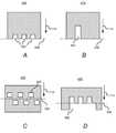
도 2A 내지 도 2C에 도시된 바와 같이 위치결정된 한쌍의 개구(124)를 갖는 것처럼 마스크(122)를 위에서 특별히 언급하였지만, 다른 개구(124)(또는 동등한 결결부) 형태를 갖는 마스크가 장치(100, 200)에서 구현될 수 있음이 이해되어야 한다. 다른 개구(124)는 도 3A 내지 도 3C에 도시된 배향 이외의 각각에 관하여 상이한 배향을 갖는 자성-배향 가능한 박편의 세트를 초래할 수 있다. 장치(100, 200)에서 구현될 수 있는 다른 개구 형태를 갖는 마스크(400 내지 430)의 예가 도 4A 내지 도 4F에 도시되어 있다.Although the
예로써, 도 4A에 도시된 마스크(400)는 마스크(400)의 에지를 따라서 형성된 복수의 개구(402)를 갖는 것처럼 도시되어 있다. 개구(402)가 형성된 마스크(400)의 에지는 기재(116)의 공급 방향(114)을 따라서 자계선(202)의 회전대칭축을 나타내는 선(206)(도 2A 내지 도 2C)에 맞닿도록 위치결정되는 마스크(400)의 에지일 수 있다. 도 4B에 도시된 마스크(410)는 공급 방향(114)을 따라서 세장형으로 된 개구(402)를 갖는 것처럼 도시되고, 여기서 개구(402)는 자계선(202)의 회전대칭축을 나타내는 선(206)에 맞닿도록 위치결정되는 마스크(410)의 에지에 형성된다.By way of example, the
도 4C에 도시된 마스크(420)는 공급 방향(114)에 관하여 자계선(202)의 반사대칭축을 나타내는 선(206)의 반대쪽 면 상에 위치결정된 복수의 개구(402)를 갖는 것처럼 도시되어 있다. 복수의 개구(402) 중 인접한 것은 또한 공급 방향(114)에 수직인 방향을 따라서 서로에 관하여 오프셋된 것처럼 도시되어 있다. 도 4D에 도시된 마스크(430)는 선(206)의 반대쪽 면 상에 더 큰 개구(402) 및 벡터힘(202)의 회전대칭축을 나타내는 선(206)의 한쪽 면상에 복수의 개구(402)를 갖는 것처럼 도시되어 있다. 또한, 더 큰 개구(402)는 공급 방향(114)에 수직인 방향을 따라서 가장 우측의 더 작은 개구(402)를 넘어 연장되는 것처럼 도시되어 있다.The
또 다른 예에서, 복수의 개구(402)는 대안적으로 일부가 선(206)의 한쪽에 위치결정되고 나머지가 그 반대쪽에 위치결정된 것과는 반대로 선(206)의 동일한 쪽 상에 위치결정될 수 있다. 예를 들어, 개구(402)의 각각은 선(206)의 공급 방향(114)에서 위치결정될 수 있다. 대안적으로, 개구(402)의 각각은 선(206)의 공급 방향(114)과는 반대쪽에 위치결정될 수 있다.In another example, the plurality of
마스크(122)는 침착된 유체 캐리어 상에 복사선원(120)으로부터의 복사선 풋프린트를 제공할 수 있다. 마스크(122)를 조명하는 복사선원에 대해서, 마스크(122)의 개구(124)는 복사선 풋프린트를 획정하며, 이에 따라서 복사선원(120)으로부터의 복사선은 기재 상에 방출된다. 몇몇 예에서, 기재(116)가 복사선 풋프린트로 침착된 잉크를 이동시킴에 따라서 경화가 시작된다. 마스크(122), 및 그 점에 대해서, 마스크(122) 및 복사선원(120)에 의해 획정된 복사선 풋프린트는 선두 에지(leading edge)를 갖는 것으로 보일 수 있다. 선두 에지는 복사선이 우선 유체 캐리어(118) 상에 방출되는 위치의 궤적으로서 정의될 수 있다.
도 4E 및 도 4F는 마스크가 복사선 풋프린트의 선두 에지를 획정하는 두 실시예를 제공한다. 마스크(440)에 대해서, 선두 에지(442)는 마스크(440)의 우측에 예시된다. 공급 방향(114)에서의 선두 에지(442)의 정도는 변수 x로 표시된다. 마스크(450)는 공급 방향(114)에서의 선두 에지(452)의 정도가 재차 변수 x로 표시되는 다른 실시예를 예시한다. 도 4E 및 도 4F에 도시된 바와 같이, 선두 에지는 불연속적일 수 있다. 다른 예에서, 선두 에지(예컨대, 도 6A의 마스크의 선두 에지)는 공급 방향(114)을 따르는 정도를 갖는 연속적인 부분을 포함할 수 있다. 선두 에지의 정도의 값은 0.5㎜ 내지 30㎜, 또는 1㎜ 내지 20㎜일 수 있다. 몇몇 예에서, 그 정도는 2㎜ 미만 또는 1㎜ 미만일 수 있다. 다른 예에서, 그 정도는 10㎜ 초과 또는 20㎜ 초과일 수 있다.4E and 4F provide two embodiments in which the mask defines the leading edge of the radiation footprint. For
몇몇 실시예에서, 외부 자기 유도는 선두 에지의 전부 또는 적어도 일부분을 따라서 방향이 변한다. 도 4G는 마스크(460)의 선두 에지에서 1 및 2로 표기된 두 점에서 외부 자기 유도의 방향의 상대적 변동을 예시하며, 여기서


직교 투영에 관하여, 평면(462 및 464)은 등가인 점에 유의해야 한다. 즉, 이 평면(462 및 464)은 직교 투영을 정의할 목적으로 동치류(equivalence class)에 속할 수 있다. 따라서, 직교 투영을 기술할 경우, 기재 속도 벡터를 포함하고 기재에 대해서 법선 방향인 단지 하나의 평면이 고려될 필요가 있을 수 있다. 좌표계(470)는 직교 투영을 기술할 경우 유용할 수 있다. 좌표계(470)에 대해서 x-축 및 y-축은, 기재가 마스크(460)의 선두 에지의 근방에서 평탄한 경우, 또는 동등하게, x-y 평면이 자성 잉크(대안적으로 유체 캐리어에 분산된 자성-배향 가능한 박편으로서 지칭됨)의 평면 또는 복사선 풋프린트에 놓이는 경우에 대해서 기재의 평면에 놓이며, 여기서 x-축은 기재 이동 방향에 대해서 평행하다. z-축은 기재의 평면(또는 자성 잉크 또는 복사선 풋프린트)에 대해서 법선 방향이다.It should be noted that with respect to orthogonal projection, planes 462 and 464 are equivalent. That is, these
평면(462 및 464)은 좌표계(470)의 x-z 평면에 평행하며, 직교 투영을 고려할 경우, x-z 평면 및 평면들(464 및 466)은 이들 평면 상에의 벡터의 직교 투영이 동일한 결과를 내기 때문에 동일한 동치류에 속한다. 평면(462 및 464)은 y-축의 방향에서의 x-z 평면의 변형이다.The
기재가 롤러에 대해서 만곡된 경우에, 좌표계(470)는 y-축이 롤러축에 평행하고/하거나 롤러축과 일치하는 좌표계로 일반화될 수 있다. x-축은 기재 속도 벡터를 따라 지향될 수 있지만, 이것은 반드시 필요한 것은 아닌데, 그 이유는 회전된 좌표계를 얻기 위하여 y-축을 중심으로 좌표계(470)의 z-축을 회전시키는 것이 직교 투영을 변화시키지 않기 때문이다. 즉, x-z 평면 상에 벡터의 직교 투영은 회전된 좌표계에 대해서 x-z' 평면 상에 벡터의 직교 투영으로서 동일한 결과가 얻어지며, 여기서 회전은 y-축을 중심으로 이루어진다. 따라서, 평면 상에 외부 자기 유도의 직교 투영을 기술할 경우, 평면은 기재 속도 벡터를 포함하고 기재에 대한 법선 방향으로서 취해질 수 있거나, 또는 기재가 롤러에 대해서 만곡된 경우에 대해서, 평면은 롤러축에 대해서 법선 방향으로서 취해질 수 있다.In the case where the substrate is curved with respect to the roller, the coordinate
기재가 롤러에 대해서 만곡되는 경우에 대해서, 또한 직교 투영에 대한 평면을, 기재의 속도 벡터를 포함하고 기재에 대해서 법선 방향에 있는 평면을 기재하는 것이면 충분하다. 여기서, 기재가 롤러 둘레에 감기는 위치에서의 "법선"은 롤러축에 대해서 법선 방향이고 그 위치를 포함하는 벡터로서 취해질 수 있는 그 위치에서의 국부적 법선을 지칭한다. 속도 벡터에 관하여, 롤러 둘레에 감겨진 경우 일부 위치에서의 기재의 속도 벡터가 방향이 일정하지 않지만, 위치의 함수이면, 그럼에도 불구하고 롤러의 축에 법선 방향인 평면에 놓인다. 롤러축에 법선 방향인 평면은 직교 투영의 목적을 위하여 동치류이므로, 기재의 속도 벡터를 포함하고 기재에 법선 방향의 평면 상에의 외부 자기 유도의 직교 투영은 또한 롤러축에 대해서 법선 방향의 평면 상에의 직교 투영으로서 취해질 수 있다.In the case where the substrate is curved with respect to the roller, it is sufficient to describe a plane for orthogonal projection, which includes the velocity vector of the substrate and is in the normal direction to the substrate. Here, the "normal" at the position where the substrate is wound around the roller refers to the local normal at that position which is in the direction normal to the roller axis and can be taken as a vector including that position. Regarding the velocity vector, the velocity vector of the substrate at some positions when it is wound around the roller is not constant in direction, but if it is a function of the position, it nonetheless lies in a plane that is in the direction normal to the axis of the roller. Since the plane in the direction normal to the roller axis is equivalent for the purpose of orthogonal projection, the orthogonal projection of the external magnetic induction onto the plane in the direction normal to the base material and containing the velocity vector of the base material is also a plane in the direction normal to the roller axis. It can be taken as an orthogonal projection onto the image.
따라서, 복사선 풋프린트에 적용되는 기재의 부분이 평탄하든지 또는 롤러에 대해서 감겨 있든지 간에, 복사선 풋프린트의 선두 에지를 따라서 외부 자기 유도의 직교 투영을 기술할 목적으로, 기재의 속도 벡터를 포함하고 기재에 대해서 법선 방향인 평면 상에 직교 투영을 취하는 것이면 충분하다.Thus, whether the portion of the substrate that is applied to the radiation footprint is flat or wound about a roller, for the purpose of describing the orthogonal projection of external magnetic induction along the leading edge of the radiation footprint, it contains the velocity vector of the substrate and It is sufficient to take orthogonal projection on a plane that is a normal direction to the substrate.
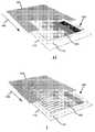
이제 도 4H 및 4I로 되돌아가면, 기재(482)가 축을 중심으로 회전함에 따라서 배향된 자성-배향 가능한 박편이 기재(482)를 가로질러 합성 이미지의 직교-시차 이동(ortho-parallactic motion)을 초래할 수 있도록 자성-배향 가능한 박편을 배향시키도록 구현될 수 있는 마스크(480)와 물품(482)의 사시도를 각각 도시하고 있다. 직교-시차 이동 또는 효과는 관찰자로부터 멀리 또는 관찰자를 향하여 물품(482)의 상부 에지를 경사지게 함으로써 기술되며, 관찰자는 좌측에서 우측 또는 우측에서 좌측으로 이동하는 반사광의 밝은 형상을 인지할 수 있다. 다른 예로서, 관찰자로부터 멀리 또는 관찰자를 향하여 좌측 에지를 기울임으로써, 관찰자가 상부에서 하부로 또는 하부에서 상부로 이동하는 반사광의 밝은 형상을 인지할 수 있다. 몇몇 예에서, 효과가 인지되는 방식은, 자성-배향 가능한 박편이 물품(482) 상에 또는 내에 배치되는 방식, 상부 에지가 관찰자로부터 멀리 또는 관찰자를 향하여 배치되는지의 여부, 및/또는 광원의 위치, 강도 및/또는 거리에 따라 좌우될 수 있다. 대안적으로, 직교-시차 광학 이동 또는 효과는, 광원에 따라서 축을 중심으로 물품을 회전시키는 관찰자가 회전축을 따라서 이동하는 반사 형상 또는 이미지를 관찰하도록 회전축(물품에 놓여 있는 축)이 존재하는 것에 의해서 기술될 수 있다. 직교-시차 광학 이동 또는 효과는 물품의 다른 구획보다 더 밝거나 또는 더 어둡게 보이는 형상과 같은 광학 특징부가 물품의 경사 방향에 직교하는 방향으로 물품을 가로질러 이동하도록 보이는 광학 효과로서 더욱 기술될 수 있다. 따라서, 예를 들어, 물품이 수평축을 중심으로 경사질 경우, 광학 특징부는 길이방향으로 이동하도록 보일 수 있다.Returning now to Figures 4H and 4I, as the
도 4H에 도시된 바와 같이, 물품(482)은 기재(116)와 유체 캐리어(118)를 포함할 수 있으며, 둘 다 위에서 기재되어 있다. 또한, 마스크(480)는 물품(482)이 화살표(486)로 표시된 방향으로 이동함에 따라서, 물품(482)의 폭을 가로질러 상이한 위치에 있는 자성-배향 가능한 박편(484)이 서로에 관하여 다수의 회전 위치에 로킹될 수 있도록 단차 형태를 포함할 수 있다. 자성-배향 가능한 박편(484)의 회전 위치는 도 4H에서 상이한 음영을 갖는 것처럼 도시되며, 도 4I에서 상이한 각도를 갖는 것처럼 도시된다. 위에서 논의된 바와 같이, 자성-배향 가능한 박편(484)은 자성-배향 가능한 박편(484)에의 자계의 인가를 통해서 그리고 마스크(480)와 일치하는 구성에서 적어도 부분적으로 유체 캐리어(118)를 고형화시키기 위하여 복사선의 인가를 통해서 도 4I에 도시된 각도로 회전될 수 있다. 또한, 도 4J는 자성-배향 가능한 박편(484)이 -40° 내지 40°의 범위인 각도에서 배향되는 실시예를 도시한다.As shown in FIG. 4H,
물품(482)의 광학 효과는 물품(482)이 광원에 대해서 앞뒤로 경사질 경우 옆으로 이동하는 밝은 밴드일 수 있다. 운동학적 광(또는 밝은) 밴드는 합성 운동학적 이미지를 생성하도록 물품(482)을 작성함으로써 더 매력적이거나 호소력 있게 만들어질 수 있으며, 이 물품은 물품(482)이 이동되는 방향에 관하여 물품(482)의 마진 내에서 횡방향으로 이동한다. 예로써, 합성 운동학적 이미지는 대상체, 기호, 숫자, 문자, 이들의 조합 등의 윤곽일 수 있다.The optical effect of
물품(482)은 보안 요소로서 도 4K에 도시된 바와 같이 유가 물품(488) 상에 제공될 수 있다. 유가 물품(488)은 지폐로서 도시되고, 물품(482)은 직사각-형상 보안 요소(702)로서 도시되었다. 물품 또는 보안 요소(482)는 단지 예시적이며, 보안 요소로서 또는 지폐와 함께 사용 또는 직사각-형상으로 제한되지 않음에 유의해야 한다. 예를 들어, 보안 요소(482)는, 라벨, 패키징, 광고 등을 포함하지만 이들로 제한되는 것은 아닌 임의의 물품 상에서 사용될 수 있고, 임의의 형상을 가질 수 있다. 보안 요소(482)에 그려진 상이한 형상은 상이한 각도에서 반사되는 광을 나타날 수 있고, 따라서 유가 물품(488)의 경사각에 따라서, 보안 요소(482)의 상이한 구획이 합성 이미지로서 보여질 수 있다. 또한, 유가 물품(488)의 회전을 통해서, 합성 이미지는 해당 합성 이미지가 이동하는 것으로 보일 수 있으므로 합성 운동학적 이미지로서 보여질 수 있다.
합성 운동학적 이미지는 축(490)에 관하여 각종 경사각에서 유가 물품(488)을 도시하는 도 4L 및 도 4M과 관련하여 더욱 기술된다. 이들 도면에 도시된 바와 같이, 광원(492)으로서의 광이 보안 특징부(482)로부터 반사됨에 따라서 관찰자가 합성 이미지로서 보는 보안 특징부(482)의 구획은 화살표(494) 및 더 가볍거나 더 밝은 밴드로 표시된 바와 같이 이동될 수 있다. 실시예에 따르면, 보안 특징부(482) 내 자성-배향 가능한 박편은, 유가 물품(488)이 경사짐에 따라서 합성 이미지의 색이 변할 수 있도록, 예컨대, 자성-배향 가능한 박편이 금색-대-녹색 안료를 가질 수 있도록 각종 색 및/또는 색-변환 안료를 포함할 수 있다.The synthetic kinematic image is further described with respect to FIGS. 4L and 4M showing the valued
이제 도 4N으로 되돌아가면, 마스크(480) 내 개구 또는 절결부가 상이한 폭을 갖는 마스크(480)의 실시예가 도시되어 있다. 마스크(480) 내 단차의 불균일한 폭이 줌 효과를 초래할 수 있으며, 여기서 단차 밑에 위치된 물품(482)의 부분은 더 작은 폭을 갖는 단차 밑에 위치된 물품(482)의 부분과 비교해서 더 큰 외관을 갖는다. 도 4N에 도시된 실시예에서, 문자 "2", "5", "7", "A" 및 "3"이 유체 캐리어(118)를 갖는 기재(116) 상에 인쇄될 수 있다. 즉, 길로슈(Guilloche) 또는 기타 그래픽 아트가 기재(116) 상에 제공될 수 있고, 자성 잉크일 수 있는 유체 캐리어(118)는 도 4N에 표시된 문자로 인쇄되거나 도포될 수 있다. 물품(482)은 도 4O에 도시된 바와 같이 유가 물품(488) 상에 보안 요소로서 제공될 수 있다. 이 도면에 도시된 바와 같이, 정상 시야각 하에, 숫자 "3"은 가장 밝게 보일 수 있거나 또는 다르게는 가장 눈에 띄는 합성 이미지일 수 있다.Turning now to FIG. 4N, an embodiment of a
보안 요소(482)에 의해 발생된 합성 운동학적 이미지는, 축(490)에 관하여 각종 경사각에서 유가 물품(488)을 도시하는 도 4P 및 도 4Q와 관련하여 더 기술된다. 이들 도면에 도시된 바와 같이, 광원(492)으로부터의 광이 보안 특징부(482)로부터 반사됨에 따라서 관찰자가 합성 이미지로서 보게 되는 보안 특징부(482)의 구획이 화살표(494) 및 더 가볍거나 또는 더 밝은 밴드로 표시된 바와 같이 이동될 수 있다. 따라서, 예를 들어, 도 4P에서, 숫자 "7"은 보안 요소(482) 내 문자 중에서 가장 눈에 띄는 외관을 가질 수 있다. 부가적으로, 유가 물품(488)이 도 4Q에 도시된 바와 같이 더욱 경사짐에 따라서, 숫자 "2"는 보안 요소(482) 내 문자 중에서 가장 눈에 띄는 외관을 가질 수 있다. 실시예에 따르면, 보안 특징부(482) 내 자성-배향 가능한 박편은, 유가 물품(488)이 경사짐에 따라서 합성 이미지의 색이 변할 수 있도록, 예컨대, 자성-배향 가능한 박편은 금색-대-녹색 안료일 수 있도록 각종 색 및/또는 색-변환 안료를 포함할 수 있다.The synthetic kinematic image generated by the
이제 도 5A로 되돌아가면, 본 개시내용의 다른 실시예에 따른 자성-배향 가능한 박편을 배향시키기 위한 장치(500)의 평면도가 도시되어 있다. 도 5A에 도시된 장치(500)는 도 2B와 관련하여 위에서 기재된 것과 동일한 특징부의 다수를 포함하며, 따라서, 이들 공통 특징부는 도 5A와 관련하여 상세히 기재되지 않을 것이다. 그러나, 도 5A에 도시된 장치(500)는 장치(500) 내 마스크(502)가 쐐기-형상 개구(504)를 갖는다는 점에서 도 2B에 도시된 장치(200)와는 상이하다. 기재(116)가 공급 방향(114)으로 이동함에 따라서 쐐기-형상 개구(504)가 유체 캐리어(118)의 상이한 부분에 대한 복사선원(120)으로부터의 에너지의 인가를 초래하므로, 자계의 인가에 기인하는 영역(506) 내의 자성-배향 가능한 박편 또는 입자는 도 5A에 도시된 바와 같은 구배를 따라서 상이한 배향 및 이면각 값을 가질 수 있다. 즉, 유체 캐리어(118)의 상이한 부분은 상이한 벡터힘(202)의 영향 하에 있을 것이고(도 2A), 이에 따라서 복사선이 쐐기-형상 개구(504)를 통해서 유체 캐리어(118) 상에 인가될 경우 상이한 배향 및 이면각 값을 가질 수 있다.Turning now to FIG. 5A, a top view of an
영역(508 및 510) 내 자성-배향 가능한 박편은 영역(506)을 고형화시키는 과정에서 자계선(202)의 동일한 경사 및 감쇠 부분에 노출되지 않았을 수 있다. 대신에, 영역(508 및 510) 내 자성-배향 가능한 박편은 자계선(202)의 상이한 방향--아마도 감쇠 부분에 정렬될 수 있다. 즉, 영역(508 및 510)은 영역(508 및 510)이 마스크(502) 아래로부터 나올 경우 복사선원(120)으로부터의 복사선에 노출될 수 있고, 따라서, 그들의 즉각적인 배향에서 적어도 부분적으로 고정되어 있는 자성-배향 가능한 박편을 적어도 고형화, 예컨대, 경화시키기 시작할 수 있다. 영역(508 및 510)이 고형화되기 시작하는 동안, 이들 영역 내의 자성-배향 가능한 박편은 자계선(202)의 감쇠 부분(224)과 정렬될 수 있다. 그 결과, 영역(508 및 510) 내 자성-배향 가능한 박편은 영역(506) 내 자성-배향 가능한 박편의 배향 및 이면각 값과 비교해서 상이한 배향 및 이면각 값을 가질 수 있다.The magnetically-orientable flakes in the
실시예에 따르면, 마스크(502) 내 쐐기-형상 개구(504)의 사용은 기재(116)의 평면 내에 그리고 공급 방향(114)에 대해서 수직인 방향 또는 횡방향을 따라서 서로에 관하여 나선형 배열을 갖는 영역(506) 내 자성-배향 가능한 박편을 초래할 수 있다. 일정 구배로 배열된 영역(506) 내 자성-배향 가능한 박편의 간략화된 실시예가 도 5B에 도시되어 있다. 도 5B는, 특히, 도 5A에 도시된 유체 캐리어(118)의 영역(506)에 함유된 자성-배향 가능한 박편의 간략화된 등각도(520)를 도시한다. 다른 예에서, 유사한 효과가 각진 구획이 단차 형태를 갖는 마스크의 사용을 통해서 얻어질 수 있다.According to an embodiment, the use of the wedge-shaped
도 5B에서, 자성-배향 가능한 박편(522)은 영역(506) 내 자성-배향 가능한 박편(522)의 어레이의 길이방향 행을 따라 유체 캐리어(118)에 배열된 것처럼 도시되어 있다. 도시된 바와 같이, 행("a 내지 g")의 각각에서 자성-배향 가능한 박편(522)은 모두 기재(116)의 주된 평면에 관하여 동일한 이면각에서 배향될 수 있다. 즉, 행("a")에서 자성-배향 가능한 박편(522)은 모두 기재(116)의 주된 평면 및 기재 이동 방향(114)에 관하여 동일 각도(αa)로 배향될 수 있으며, 여기서 각도(αa)는 약 90°< αa < 180° 사이이다. 마찬가지로, 행("b")에서 자성-배향 가능한 박편(522)은 기재(116)의 주된 평면 및 기재 이동 방향(114)에 관하여 동일 각도(αb)로 배향될 수 있으며, 여기서 각도(αb)는 각도(αa)와는 상이하다. 나머지 행(c 내지 g) 내 자성-배향 가능한 박편(522)의 경사각은 또한 다른 행 내 자성-배향 가능한 박편(522)의 경사각과는 상이할 수 있다.In FIG. 5B, magneto-
도 5B에서, 자성-배향 가능한 박편(522)은 또한 영역(506)의 어레이의 횡방향 열을 따라 유체 캐리어(118)에 배열된 것처럼 도시되어 있다. 횡방향 열("A" 내지 "H")의 각각을 따른 자성-배향 가능한 박편(522)의 경사각의 값은 단차 방식으로 변한다. 예를 들어, 횡방향 열("A" 내지 "H")의 경사각의 값은 각도(δ1)(범위 180° > δ1> 90°인 것으로 도 5B에 도시됨)에서부터 각도(δn)(범위 90°> δn> 0°인 것으로 도 5B에 도시됨)까지 변한다. 단일의 횡방향 열("A") 내 자성-배향 가능한 박편(522)의 열을 따라서 경사각의 값의 변동의 결과로서, 자성-배향 가능한 박편(522)은 기재(116)의 평면 내에 놓이고 이동 방향과 직교하는 방향을 따라서 나선형 배향을 형성할 수 있다.In FIG. 5B, magneto-
영역(506) 내 자성-배향 가능한 박편(522)의 전이 광학 효과는 도 5C 내지 도 5F와 관련하여 더욱 도시되고 기재된다. 도 5C 내지 도 5F의 각각은 상이한 경사각에서의 광학 요소(530)의 실시예를 도시한다. 광학 요소(530)는 지폐, 주권 등 상에 제공될 수 있는 광학 보안 디바이스일 수 있다. 도 5C는 광학 요소(530)를 제1 각도에서, 예컨대, 광학 요소(530)에 대한 법선에 가까운 방향으로부터 본 경우의 광학 요소(530)의 광학 특징을 도시한다. 그래프(532)는, 광학 요소(530)의 좌측이 흑색으로(예컨대, 어둡게) 보이고, 광학 요소(530)의 우측이 백색으로(예컨대, 밝게) 보이며, 광학 요소(530)가 광학 요소(530)의 좌측에서부터 우측으로 흑색에서부터 백색으로 점차로 변하는 것을 도시한다.The transition optical effect of the magneto-
도 5D는 광학 요소(530)가 화살표(534)로 표시된 바와 같이 관찰자로부터 멀리 경사진 경우의 광학 요소(530)의 광학 특징의 실시예를 도시한다. 예를 들어, 광학 요소(530)의 상부는 관찰자로부터 멀리 약 15°내지 25°경사질 수 있다. 그래프(536)는 광학 요소(530)의 좌측과 광학 요소(530)의 우측이 둘 다 흑색으로(예컨대, 어둡게) 보이고 광학 요소(530)의 중심이 백색으로(예컨대, 밝게) 보이는 것을 도시한다. 도시된 바와 같이, 광학 요소(530)의 상부 부분이 관찰자로부터 멀리 경사짐에 따라서, 밝은 밴드가 광학 요소(530)의 우측으로부터 광학 요소(530)의 좌측으로 이동하는 것으로 보일 수 있다. 즉, 광학 요소(530) 내 자성-배향 가능한 박편(522)은 하나의 방향으로(예컨대, 상부에서 하부로)의 광학 요소(530)의 경사가 반대 방향으로(예컨대, 우측에서 좌측으로)의 광학적 전이를 초래하도록 배향될 수 있다.5D shows an embodiment of the optical features of
도 5E는 광학 요소(530)의 상부 부분이 관찰자로부터 더욱 멀리 경사질 경우의 광학 요소(530)의 광학 특징의 일례를 도시한다. 예를 들어, 광학 요소(530)의 상부는 화살표(538)로 표시된 바와 같이 관찰자로부터 멀리 약 25° 초과의 각도로 경사질 수 있다. 그래프(540)는 광학 요소(530)의 좌측이 백색으로(예컨대, 밝게) 보이고 광학 요소(530)의 나머지 부분이 흑색으로(예컨대, 어둡게) 보이는 것을 도시한다. 도시된 바와 같이, 광학 요소(530)의 상부 부분이 관찰자로부터 멀리 더욱 경사짐에 따라서, 밝은 밴드가 광학 요소(530)의 좌측으로 이동하는 것으로 보인다.5E shows an example of the optical features of
도 5F는 화살표(542)로 표시된 바와 같이 광학 요소(530)가 대각으로 고정된 경우 광학 요소(530)의 광학 특징의 실시예를 도시한다. 도시된 바와 같이, Z-형상 백색 밴드는 광학 요소(530)가 대각으로 고정됨에 따라서 가시적일 수 있다. 그래프(544)는 가시적인 Z-형상 밴드를 그래프로 도시하고 있다.5F shows an embodiment of the optical features of
광학 요소(530)는 정사각 형상을 갖는 것으로 묘사되었지만, 광학 요소(530)는 임의의 형상을 가질 수 있는 것임이 이해되어야 한다.Although
이제 도 6A로 되돌아가면, 본 개시내용의 다른 실시예에 따른, 자성-배향 가능한 박편을 배향시키기 위한 장치(600)의 평면도가 도시되어 있다. 도 6A에 도시된 장치(600)는 도 5A와 관련하여 위에서 기재된 것과 동일한 특징부의 다수를 포함하며, 따라서, 이들 공통 특징부는 도 6A와 관련하여 상세히 기재되지 않을 것이다. 그러나, 도 6A에 도시된 장치(600)는 마스크(602) 내의 쐐기-형상(또는 삼각형-형상) 개구(604)가 이등변 또는 등변 삼각형의 두 변을 포함한다는 점에서 도 5A에 도시된 장치(500)와는 상이하다. 삼각형-형상 개구(604)가 쐐기-형상 개구(504)와 비교해서 유체 캐리어(118)의 상이한 부분 상에 복사선원(120)으로부터의 복사선의 인가를 초래할 것임에 따라서, 자계의 인가에 기인되는 영역(606) 내 자성-배향 가능한 박편 또는 입자는 도 6A에 도시된 바와 같은 구배를 따라서 상이한 배향을 가질 수 있다. 즉, 유체 캐리어(118)의 상이한 부분은 상이한 벡터힘(자계선(202)으로서 개략적으로 도시됨)(도 2A)의 영향 하에 있을 것이고, 이에 따라서 에너지가 개구(604)를 통해서 유체 캐리어(118) 상에 인가될 경우 상이한 배향을 가질 수 있다.Turning now to FIG. 6A, a top view of an
영역(608 및 610) 내 자성-배향 가능한 박편은 영역(606)을 고형화시키는 과정에서 자계선(202)의 동일 경사 및 감쇠 부분에 노출되지 않도록 할 수 있다. 대신에, 영역(608 및 610) 내 자성-배향 가능한 박편은 자계선(202)의 상이한-아마도 감쇠 부분의 방향으로 정렬될 수 있다. 즉, 영역(608 및 610)은 영역(608 및 610)이 마스크(602) 아래로부터 나올 경우 복사선원(120)으로부터의 복사선에 노출될 수 있고, 따라서, 그들의 즉각적인 배향에서 적어도 부분적으로 고정되어 있는 자성-배향 가능한 박편을 적어도 고형화, 예컨대, 경화시키기 시작할 수 있다. 영역(608 및 610)이 적어도 부분적으로 고형화되는 동안, 이들 영역 내의 자성-배향 가능한 박편은 자계선(202)의 감쇠 부분(224)과 정렬될 수 있다. 그 결과, 영역(608 및 610) 내 자성-배향 가능한 박편은 영역(606) 내 자성-배향 가능한 박편의 배향 및 이면각 값과 비교해서 상이한 배향 및 이면각 값을 가질 수 있다.The magnetically-orientable flakes in the
실시예에 따르면, 마스크(602)의 쐐기-형상 개구(604)의 사용은 기재(116)의 평면 내에 그리고 공급 방향(114)에 수직인 방향으로 따라서 서로에 관하여 이중-나선형 배열을 갖는 영역(606) 내 자성-배향 가능한 박편을 초래할 수 있다. 일정 구배로 배열된 영역(606) 내 자성-배향 가능한 박편의 간략화된 실시예가 도 6B에 도시되어 있다. 도 6B는, 특히, 도 6A에 도시된 영역(606)에 함유된 자성-배향 가능한 박편의 간략화된 등각도(620)를 도시한다. 다른 예에서, 유사한 효과는 각진 구획이 각각 단차 형태를 갖는 마스크의 사용을 통해서 얻어질 수 있다.According to an embodiment, the use of the wedge-shaped
도 6B에서, 자성-배향 가능한 박편(622)은 두 구획(624 및 626)으로 구성된 것처럼 도시된 영역(606) 내 자성-배향 가능한 박편(622)의 어레이의 길이방향 행을 따라 배열된 것처럼 도시되어 있다. 구획(624 및 626)의 각각은 삼각형 형상의 개구(604)의 선단과 일치하는 중심선(628)의 대향 측면 상에 배열된 것처럼 도시되어 있다. 도시된 바와 같이, 인접한 길이방향으로 연장된 행에서 자성-배향 가능한 박편(622)의 서브세트의 각각은 기재(116)의 주된 평면에 관하여 동일한 이면각에서 배향될 수 있다. 즉, 제1 구획(624) 내 행들 중 하나의 행 내 자성-배향 가능한 박편(622)은 모두 기재(116)의 주된 평면 및 기재 이동 방향(114)에 관하여 동일한 각도(α)로 배향될 수 있으며, 여기서 각도(α)는 약 0°< α < 180°사이이다. 마찬가지로, 제1 구획(624)의 제2 행 내 자성-배향 가능한 박편(622)은 기재(116)의 주된 평면 및 기재 이동 방향(114)에 관하여 동일한 각도(α')로 배향될 수 있으며, 여기서 각도(α')는 각도(α)와는 상이하다. 나머지 길이방향으로 연장되는 행 내 자성-배향 가능한 박편(622)의 이면각은 또한 다른 행 내 자성-배향 가능한 박편(622)의 이면각과는 상이할 수 있다.In FIG. 6B, magneto-
도 6B에서, 자성-배향 가능한 박편(622)은 또한 영역(606) 내 화살표의 횡방향 열을 따라서 유체 캐리어에 배열된 것처럼 도시되어 있다. 제1 구획(624) 내 횡방향 열의 각각을 따른 자성-배향 가능한 박편(622)의 이면각의 값은 단차 방식으로 변한다. 예를 들어, 횡방향 열 내 경사각의 값은 각(δ1)(0° < δ1< 180°의 범위인 것으로 도 6B에 도시됨)의 값에서부터 각(δn)의 값으로 변한다. 제1 구획(624)의 단일의 횡방향 열에서 자성-배향 가능한 박편(622)의 열을 따른 이면각의 값의 이 변화의 결과로서, 제1 구획(624) 내 자성-배향 가능한 박편(622)은 나선형 배향을 형성할 수 있다. 제2 구획(626)의 횡방향 열 내 자성-배향 가능한 박편(622)은 상이한 나선형 배향을 갖도록 배열되고 배향될 수 있다. 두 구획(624 및 626) 내 자성-배향 가능한 박편(622)은, 제2 구획(626) 내 자성-배향 가능한 박편에 시계방향 나선형 형태를 제공하고 그리고 제1 구획(624) 내 자성-배향 가능한 박편에 반시계방향 나선형 형태를 제공하도록 거울 복사 형태로 배열되고 배향될 수 있다. 그와 같이, 영역(606) 내 자성-배향 가능한 박편(622)의 횡방향 열의 각각 내 자성-배향 가능한 박편은 도 6B에 도시된 바와 같이 이중 나선형 배향을 가질 수 있다. 영역(606) 내 자성-배향 가능한 박편(622)의 전이 광학 효과는 도 6C 내지 도 6E에 관하여 더욱 도시되고 기재된다. 도 6C 내지 도 6E의 각각은 상이한 경사각에서의 광학 요소(630)의 일례를 도시한다. 광학 요소(630)는 광학 보안 디바이스일 수 있고, 이것은 지폐, 주권 등 상에 제공될 수 있다. 도 6C는 광학 요소(630)가 제1 각도에서, 예컨대, 광학 요소(630)에 대해서 법선 방향으로부터 또는 법선에 가깝게 관찰될 경우 광학 요소(630)의 광학적 특징을 도시한다. 그래프(632)는 광학 요소(630)의 중심이 백색으로(예컨대, 밝게) 보이고 광학 요소(630)가 광학 요소(630)의 좌측 및 우측 측면에 더 가까울수록 점차로 더 검게(예컨대, 더 어둡게) 되는 것을 도시한다.In FIG. 6B, magneto-
도 6D는 광학 요소(630)의 상부 부분이 화살표(634)로 표시된 바와 같이 관찰자로부터 멀리 경사질 경우 광학 요소(630)의 광학적 특징의 일례를 도시한다. 예를 들어, 광학 요소(630)의 상부는 관찰자로부터 멀리 약 15° 경사질 수 있다. 광학 요소(630)의 서술은 도 6C에 도시된 넓은 밝은 밴드가 광학 요소(630)의 좌측 및 우측 에지로 동시에 이동하는 더 작은 폭의 2개의 밝은 밴드로 분할될 수 있는 것을 도시한다. 그래프(636)는 광학 요소(630)의 경사가 2개의 백색 피크를 초래할 수 있는 것을 도시한다. 즉, 광학 요소(630) 중의 자성-배향 가능한 박편(622)은 하나의 방향으로(예컨대, 위에서 아래로) 광학 요소(530)의 경사가 반대 방향으로(예컨대, 좌측에서 우측으로 그리고 우측에서 좌측으로) 다수의 광학 변이를 초래할 수 있도록 배향될 수 있다.6D shows an example of the optical characteristics of
도 6E는 광학 요소(630)의 상부 부분이 관찰자로부터 더 멀리 경사질 경우 광학 요소(630)의 광학적 특징의 일례를 도시한다. 예를 들어, 광학 요소(630)의 상부는 화살표(638)로 표시된 바와 같이 관찰자로부터 약 15°초과의 각도로 경사질 수 있다. 도시된 바와 같이, 추가의 경사는 백색 밴드가 좌측 및 우측 에지에 더 가깝게 되고 더 좁게 될 수 있게 한다. 또한, 광학 요소(630)의 중심 부근의 더 어두운 구역은 더 넓게 될 수 있다. 그래프(640)는 백색 피크가 에지에 더 가깝고 더 좁게 되는 한편 중앙부에서 더 어두운 구역은 폭이 증가되는 것을 도시한다.6E shows an example of the optical features of
광학 요소(630)가 정사각 형상을 갖는 것으로 묘사되었지만, 광학 요소(630)는 임의의 형상을 가질 수 있음이 이해되어야 한다.Although
도 7 내지 도 10을 참조하면, 본 개시내용의 실시예에 따른, 자성-배향 가능한 박편을 배향시키기 위한 방법(700 내지 1000)의 흐름도가 각각 도시되어 있다. 방법(700 내지 1000)은 위에서 논의된 장치(100, 200, 500 및 600)에 관하여 기재된다. 그러나, 방법(700 내지 1000)은 장치(100, 200, 500 및 600)의 구성과는 다른 구성을 갖는 장치에 의해 구현될 수 있음이 이해되어야 한다. 방법(700 내지 1000)의 각각은 단지 예시적이다. 방법(700 내지 1000)은 더 많거나 더 적은 단계를 포함할 수 있다. 방법(700 내지 1000)의 단계들은 임의의 순서로 수행될 수 있다.7-10, a flow diagram of a method 700-1000, respectively, for orienting magnetically-orientable flakes, in accordance with an embodiment of the present disclosure, is shown. Methods 700-1000 are described with respect to
우선 도 7을 참조하면, 블록 702에서, 자성-배향 가능한 박편을 함유하는 유체 캐리어(118)는 선택적으로 기재(116) 상에 도포될 수 있다. 유체 캐리어(118)의 도포는 유체 캐리어(118)가 기재(116) 상에 미리 도포된 경우에서 선택적일 수 있다.Referring first to FIG. 7, at
블록 704에서, 기재(116) 및 유체 캐리어(118)가 자계를 통해서 이동될 수 있다. 본 명세서에서 기재된 바와 같이, 자계는 유체 캐리어(118) 내의 자성-배향 가능한 박편이 다수의 배향 중 하나로 각각 배향되도록 영향을 미칠 수 있다. 다수의 배향은 기재(116)의 평면에 관하여 이면각일 수 있다. 실시예에 따르면, 자계는 적어도 0.0001 테슬라의 강도를 갖는다.At
블록 706에서, 자계를 통한 기재(116)의 이동 동안에, 복사선은 유체 캐리어의 복수의 선택된 부분에서 유체 캐리어(118)를 경화시키고 자계에 의해 영향을 받음에 따라서 각각의 각도 배향에서 복수의 선택된 부분 내의 자성-배향 가능한 박편을 고정시키기 위하여 마스크(122) 내의 적어도 하나의 개구(124)를 통해서 유체 캐리어(118)의 복수의 선택된 부분 상에 인가될 수 있다. 실시예에 따르면, 복사선은 제1 선택된 부분 내의 자성-배향 가능한 박편이 제1 배향에서 고정되고 제2 선택된 부분 내의 자성-배향 가능한 박편이 제2 배향에서 고정되도록 인가될 수 있고, 여기서 제1 배향은 제2 배향과는 상이하다. 복사선은 또한 제3 선택된 부분 내의 자성-배향 가능한 박편이 제3 배향에서 고정되도록 인가될 수 있으며, 여기서 제3 배향은 제1 배향 및 제2 배향과는 상이하다.At
본 명세서에서 논의된 바와 같이, 기재(116)는 자계를 통해서 공급 방향(114)을 따라서 이동될 수 있고, 복사선은, 다른 부분에서 자성-배향 가능한 박편의 배향각과는 상이하고, 또한 공급 방향(114)을 따라 연장되고 기재(116) 표면에 대해서 정접하는 평면에 관하여 교차 각도와는 상이한 각각의 배향각에서 복수의 선택된 부분 내의 자성-배향 가능한 박편을 고정시키도록 인가될 수 있다. 또한, 복사선은 복수의 선택된 부분 내의 자성-배향 가능한 박편이 자계의 각각의 벡터힘과 실질적으로 정렬될 경우 복수의 선택된 부분 상에 인가될 수 있다. 또한, 자계는 적어도 하나의 고정 자석(102)에 의해 발생될 수 있고, 기재(116)는 마스크(122)와 자석(102) 사이에서 이동될 수 있다. 일례에서, 기재(116)는 적어도 약 0.3 미터/분(1 ft/분)의 속도에서 이동될 수 있다. 다른 예에서, 기재(116)는 약 1.5 미터/분(5 ft/분) 내지 약 180 미터/분(600 ft/분)의 속도로 이동될 수 있다.As discussed herein, the
이제 도 8로 되돌아가면, 블록 802에서, 기재(116)는 복사선을 제공하는 복사선 풋프린트 및 자계를 통해서 제1 방향(114)으로 이동될 수 있다. 자계는 적어도 0.0001 테슬라의 강도를 가질 수 있다. 자성-배향 가능한 박편을 가진 잉크(예컨대, 유체 캐리어(118))가 기재(116) 상에 배치되고 복사선 풋프린트는 선두 에지를 갖는다. 자계는 또한 적어도 하나의 자석(102)에 의해 발생될 수 있고, 복사선 풋프린트는 적어도 하나의 자석(102)에 관하여 고정식일 수 있다.Turning now to FIG. 8, at
블록 804에서, 자계를 통한 기재(116)의 이동 동안, 복사선은 기재(116)의 일부분이 제1 방향(114)을 따라서 선두 에지의 규모 내에 있을 경우 기재(116)의 일부분에 인가될 수 있다. 위에서 논의된 바와 같이, 복사선 풋프린트의 선두 에지는 공급 방향(114)에서 변화될 수 있고, 마스크(122)의 개구개구(124)를 통해서 제공될 수 있다. 또한, 선두 에지는 제1 방향으로 적어도 2㎜ 규모를 갖는 연속 에지 및 기재(116)의 평면에 평행하고 제1 방향에 대해서 법선 방향으로 적어도 2㎜ 규모를 가질 수 있다.At
이제 도 9를 참조하면, 블록 902에서, 유체 캐리어가 상부에 침착된 기재(116)는 경화 복사선을 제공하는 복사선 풋프린트 및 외부 자기 유도에 관하여 이동될 수 있다. 유체 캐리어는 자성-배향 가능한 박편을 포함할 수 있고, 복사선 풋프린트는 기재 이동 방향으로 0-이외 규모(non-zero extent)를 가진 선두 에지를 가질 수 있다.Referring now to FIG. 9, at
블록 904에서, 유체 캐리어는 유체 캐리어가 복사선 풋프린트에서 이동됨에 따라서 경화 복사선으로 경화될 수 있다. 유체 캐리어는 복사선 풋프린트에서 이동하면서 부분적으로 또는 완전히 경화될 수 있다. 몇몇 예에서, 복사선 풋프린트의 선두 에지는 기재가 공급 방향에서 이동함에 따라서 경화 복사선에 먼저 노출된 기재 상의 점일 수 있다. 몇몇 예에서, 유체 캐리어는 유체 캐리어가 선두 에지를 통과함에 따라서 경화되기 시작한다. 또한, 선두 에지의 적어도 부분에 대해서, 외부 자기 유도는 평면 상에 직교 투영을 갖고 평면이 기재(116)에 대해서 법선인 기재 속도 벡터를 포함한다. 직교 투영은 적어도 0.01 라디안만큼 방향이 변화될 수 있고, 적어도 0.0001 테슬라의 강도를 가질 수 있다. 직교 투영은 적어도 0.05 라디안만큼 방향이 변화될 수 있다. 실시예에 따르면, 선두 에지는 기재 이동 방향으로 적어도 2㎜의 규모를 갖고 연속 에지를 가질 수 있다. 연속 에지는 또한 기재 이동 방향에 대해서 법선 방향으로 기재(116)를 따라서 적어도 2㎜ 규모를 가질 수 있다. 부가적으로 또는 대안적으로, 복사선 풋프린트는 외부 자기 유도에 관하여 고정식일 수 있다.At block 904, the fluid carrier may be cured with hardening radiation as the fluid carrier moves in the radiation footprint. The fluid carrier can be partially or completely cured while moving in the radiation footprint. In some examples, the leading edge of the radiation footprint can be a point on the substrate that is first exposed to hardened radiation as the substrate moves in the supply direction. In some examples, the fluid carrier begins to cure as the fluid carrier passes through the leading edge. Further, for at least a portion of the leading edge, the external magnetic induction includes a substrate velocity vector that has an orthogonal projection on the plane and the plane is normal to the
이제 도 10으로 되돌아가면, 블록 1002에서, 유체 캐리어(118)가 상부에 침착된 기재(116)는 경화 복사선을 제공하는 복사선 풋프린트 및 외부 자기 유도에 대해서 이동될 수 있다. 유체 캐리어(118)(또는 잉크)는 자성-배향 가능한 박편을 포함할 수 있고 복사선 풋프린트는 기재 이동 방향에서 0-이외 규모를 갖는 선두 에지를 가질 수 있다. 예를 들어, 선두 에지는 기재 이동 방향으로 적어도 2㎜의 규모를 갖는 연속 에지를 포함할 수 있다. 연속 에지는 부가적으로 또는 대안적으로 기재 이동 방향에 대해서 법선 방향으로 기재를 따라 적어도 2㎜ 규모를 가질 수 있다.Returning now to FIG. 10, at block 1002, the
블록 1004에서, 자성-배향 가능한 박편은 외부 자기 유도에 의해 배향될 수 있고, 여기서 배향의 이면각의 값은 선두 에지의 적어도 부분을 따라서 적어도 0.01 라디안만큼 변화될 수 있다.At
블록 1006에서, 유체 캐리어(118)는, 유체 캐리어(118)가 복사선 풋프린트에서 이동함에 따라서 경화 복사선으로 경화될 수 있다. 유체 캐리어(118)는 우선 복사선 풋프린트에서 경화 복사선에 노출될 수 있다. 몇몇 예에서, 유체 캐리어(118)는 유체 캐리어가 선두 에지를 지님에 따라서 경화되기 시작한다. 실시예에 따르면, 복사선 풋프린트는 외부 자기 유도에 관하여 고정식일 수 있고, 복사선원(120)에 의한 마스크(122)의 개구(124)의 조명을 통해서 제공될 수 있다. 부가적으로 또는 대안적으로, 외부 자기 유도의 직교 투영은 적어도 0.001 테슬라의 강도를 가질 수 있고, 자기 유도는 적어도 0.05 라디안만큼 방향을 변화시킬 수 있다.At block 1006, the
실시예에 따르면, 본 명세서에 개시된 방법(700 내지 1000) 중 어느 하나 또는 전부는 물품이 위에서 논의된 바와 같이 유체 캐리어의 다수의 층을 포함하도록 제작될 수 있도록 장치(100)의 다수의 스테이션에서 수행될 수 있다.According to an embodiment, any one or all of the methods 700-1000 disclosed herein are at multiple stations of the
본 개시내용의 전문을 통해서 구체적으로 설명되었지만, 본 개시내용의 대표적인 예는 광범위한 응용 분야에 걸쳐서 유용성을 지니며, 상기 논의는 제한으로 의도되지 않고 그와 같이 해석되어서도 안 되며, 본 개시내용의 양상의 예시적인 논의로서 제공된다.Although specifically described throughout the entirety of this disclosure, representative examples of the disclosure have utility across a wide range of applications, and the above discussion is not intended to be limiting and should not be interpreted as such, and aspects of the disclosure. Is provided as an exemplary discussion of.
본 명세서에 기술되고 예시된 것은 이의 변형의 일부와 함께 본 개시내용의 일례 및 그의 변형의 일부이다. 본 명세서에서 사용되는 용어, 설명 및 도면은 단지 예시로서 기술되며 제한하려도 의도된 것은 아니다. 본 개시내용의 정신과 범위 내에서 많은 변경이 가능하며, 본 개시내용은 이하의 청구범위 및 이의 균등 범위에 의해 정의되도록 의도되며, 모든 용어는 달리 표시되지 않는 한 이들의 최광의의 합리적인 의미를 뜻한다.What has been described and illustrated herein is an example of the present disclosure and some of its variations, along with some of its variations. The terms, description, and drawings used herein are described as examples only and are not intended to be limiting. Many changes are possible within the spirit and scope of this disclosure, and this disclosure is intended to be defined by the following claims and their equivalents, and all terms mean their broadest reasonable meaning unless otherwise indicated. do.
Claims (20)
Translated fromKorean자계를 통해서 공급 방향을 따라서 기재(substrate, 116)를 이동시키는 단계로서, 상기 기재(116)는 자성-배향 가능한 박편(magnetically-orientable flakes)을 함유하는 유체 캐리어(fluid carrier, 118)를 포함하고, 상기 자계는 상기 자성-배향 가능한 박편을 다수의 배향 중 하나로 배향시키는, 상기 기재(116)를 이동시키는 단계; 및
상기 자계를 통한 상기 기재(116)의 이동 동안에, 마스크(122)의 적어도 하나의 쐐기-형상 개구를 통해서 상기 유체 캐리어(118)의 복수의 선택된 부분 상에 복사선(radiation, 208)을 인가하여, 배향된 상기 박편을 상기 공급 방향에 수직인 방향을 따라서 서로에 대하여 나선형 또는 이중-나선형 배열로 경화시키는 단계를 포함하는, 자성-배향 가능한 박편을 배향하는 방법.As a method of orienting magnetically-orientable flakes,
Moving a substrate 116 along a supply direction through a magnetic field, wherein the substrate 116 includes a fluid carrier 118 containing magnetically-orientable flakes, and Moving the substrate 116, wherein the magnetic field orients the magnetically-orientable flake in one of a plurality of orientations; And
During movement of the substrate 116 through the magnetic field, radiation 208 is applied on a plurality of selected portions of the fluid carrier 118 through at least one wedge-shaped opening of the mask 122, Curing the oriented flakes in a helical or double-helical arrangement with respect to each other along a direction perpendicular to the feeding direction.
상기 자계를 통해서 상기 기재(116)를 이동시키기 전에 상기 기재(116) 상에 상기 자성-배향 가능한 박편을 함유하는 유체 캐리어(118)를 도포하는 단계를 더 포함하는, 자성-배향 가능한 박편을 배향하는 방법.The method of claim 1,
Orienting the magnetically-orientable flakes, further comprising the step of applying a fluid carrier 118 containing the magneto-orientable flakes on the substrate 116 before moving the base material 116 through the magnetic field. How to.
상기 기재(116) 상에 문자를 인쇄하는 단계를 더 포함하되, 상기 문자는 상기 다수의 크기 중 각각의 크기를 갖는 상기 자성-배향 가능한 박편과 정렬되도록 위치결정되는, 자성-배향 가능한 박편을 배향하는 방법.The method of claim 10,
Further comprising the step of printing a character on the substrate 116, wherein the character is positioned to be aligned with the magneto-orientable flakes having respective sizes among the plurality of sizes, magnetically orienting the oriented flakes How to.
마스크(122)의 쐐기-형상 개구를 통해 복사선(208)을 제공하는 복사선원 및 자계에 의해 제1 방향으로 기재(116)를 이동시키는 단계로서, 상기 자계는 적어도 0.001 테슬라의 강도를 갖고, 자성-배향 가능한 박편(magnetically-orientable flakes)을 갖는 잉크가 상기 기재(116) 상에 배치되고 상기 복사선(208)은 선두 에지를 갖는, 상기 기재(116)를 이동시키는 단계; 및
상기 자계를 통한 상기 기재(116)의 이동 동안에, 상기 기재(116)의 일부분이 상기 선두 에지의 상기 제1 방향에 있을 때 상기 기재(116)의 상기 일부분에 복사선(208)을 제공하여, 상기 자성-배향 가능한 박편을 상기 제1 방향에 수직인 방향을 따라서 서로에 대하여 나선형 또는 이중-나선형 배열로 경화시키는 단계를 포함하는, 자성-배향 가능한 박편을 배향하는 방법.As a method of orienting magnetically-orientable flakes,
Moving the substrate 116 in the first direction by a radiation source and a magnetic field providing radiation 208 through the wedge-shaped opening of the mask 122, the magnetic field having an intensity of at least 0.001 Tesla, -Moving the substrate 116, wherein ink with magnetically-orientable flakes is disposed on the substrate 116 and the radiation 208 has a leading edge; And
During the movement of the substrate 116 through the magnetic field, when a portion of the substrate 116 is in the first direction of the leading edge, radiation 208 is provided to the portion of the substrate 116, and the And curing the magneto-orientable flakes in a helical or double-helical arrangement with respect to each other along a direction perpendicular to the first direction.
쐐기-형상 개구를 갖는 마스크(122)로부터의 복사선 풋프린트(radiation footprint) 및 외부 자기 유도에 대해서 유체 캐리어(118)가 상부에 침착된 기재(116)를 이동시키는 단계로서, 상기 유체 캐리어(118)는 자성-배향 가능한 박편(magnetically-orientable flakes)을 포함하고, 상기 복사선 풋프린트는 공급 방향으로 0-이외 규모(non-zero extent)를 갖는 선두 에지를 갖는, 상기 기재(116)를 이동시키는 단계; 및
상기 자성-배향 가능한 박편을 상기 공급 방향에 수직인 방향을 따라서 서로에 대하여 나선형 또는 이중-나선형 배열로 경화시키는 단계를 포함하되;
상기 선두 에지의 적어도 부분에 대해서, 상기 외부 자기 유도는 평면 상에 직교 투영(orthogonal projection)을 지니고, 상기 평면은 상기 기재(116)에 대해서 법선 방향이고 기재 속도 벡터를 포함하며, 상기 직교 투영은 적어도 0.01 라디안만큼 방향이 변화되고 적어도 0.001 테슬라의 강도를 갖는, 자성-배향 가능한 박편을 배향하는 방법.As a method of orienting magnetically-orientable flakes,
Moving the substrate 116 deposited thereon with respect to external magnetic induction and a radiation footprint from the mask 122 having a wedge-shaped opening, the fluid carrier 118 ) Comprises magnetically-orientable flakes, the radiation footprint having a leading edge with a non-zero extent in the supply direction, which moves the substrate 116 step; And
Curing the magnetically-orientable flakes in a helical or double-helical arrangement with respect to each other along a direction perpendicular to the feeding direction;
For at least a portion of the leading edge, the external magnetic induction has an orthogonal projection on a plane, the plane being in a direction normal to the substrate 116 and comprising a substrate velocity vector, and the orthogonal projection is A method of orienting magneto-orientable flakes that are oriented by at least 0.01 radians and have a strength of at least 0.001 Tesla.
Applications Claiming Priority (3)
| Application Number | Priority Date | Filing Date | Title |
|---|---|---|---|
| US201662382185P | 2016-08-31 | 2016-08-31 | |
| US62/382,185 | 2016-08-31 | ||
| PCT/US2017/049730WO2018045230A1 (en) | 2016-08-31 | 2017-08-31 | Orienting magnetically-orientable flakes |
Publications (2)
| Publication Number | Publication Date |
|---|---|
| KR20190038605A KR20190038605A (en) | 2019-04-08 |
| KR102255329B1true KR102255329B1 (en) | 2021-05-26 |
Family
ID=61301683
Family Applications (1)
| Application Number | Title | Priority Date | Filing Date |
|---|---|---|---|
| KR1020197006258AActiveKR102255329B1 (en) | 2016-08-31 | 2017-08-31 | How to orient magneto-orientable flakes |
Country Status (8)
| Country | Link |
|---|---|
| US (1) | US11193002B2 (en) |
| EP (2) | EP4438317A3 (en) |
| KR (1) | KR102255329B1 (en) |
| CN (2) | CN109862970B (en) |
| CA (1) | CA3034898C (en) |
| MX (2) | MX394580B (en) |
| RU (2) | RU2752087C2 (en) |
| WO (1) | WO2018045230A1 (en) |
Families Citing this family (15)
| Publication number | Priority date | Publication date | Assignee | Title |
|---|---|---|---|---|
| MX394581B (en) | 2016-08-31 | 2025-03-24 | Viavi Solutions Inc | ITEM WITH ANGLED REFLECTIVE SEGMENTS. |
| KR102255329B1 (en)* | 2016-08-31 | 2021-05-26 | 비아비 솔루션즈 아이엔씨. | How to orient magneto-orientable flakes |
| DE102018127936A1 (en)* | 2018-11-08 | 2020-05-14 | Koenig & Bauer Ag | Device, printing machine and method for producing a security element on a substrate |
| US11618053B2 (en)* | 2019-01-15 | 2023-04-04 | Sicpa Holding Sa | Process for producing optical effect layers |
| KR102820751B1 (en)* | 2019-02-08 | 2025-06-12 | 시크파 홀딩 에스에이 | Magnetic assemblies and processes for producing optical effect layers comprising oriented non-spherical oblate magnetic or magnetizable pigment particles |
| KR102754421B1 (en)* | 2020-10-01 | 2025-01-13 | 쾨니히 운트 바우어 아게 | Machine for producing optically variable image elements |
| TW202239482A (en) | 2021-03-31 | 2022-10-16 | 瑞士商西克帕控股有限公司 | Methods for producing optical effect layers comprising magnetic or magnetizable pigment particles and exhibiting one or more indicia |
| KR20240019318A (en)* | 2021-06-11 | 2024-02-14 | 시크파 홀딩 에스에이 | Optical effect layer containing magnetic or magnetisable pigment particles and method of manufacturing the optical effect layer |
| CN113665227B (en)* | 2021-06-30 | 2022-11-22 | 惠州市华阳光学技术有限公司 | Printing machine and fixed magnetic mechanism |
| CN113547834B (en)* | 2021-07-14 | 2023-04-07 | 中钞印制技术研究院有限公司 | Multi-color light-variable printing device and printing method thereof |
| US12083813B2 (en) | 2021-10-21 | 2024-09-10 | Viavi Solutions Inc. | Printing machine and fixed patterned plate |
| US20230153557A1 (en)* | 2021-11-12 | 2023-05-18 | Viavi Solutions Inc. | Article including an image including two or more types of pixels |
| JP2025507666A (en)* | 2022-02-28 | 2025-03-21 | シクパ ホルディング ソシエテ アノニム | Method for producing an optical effect layer containing magnetic or magnetisable pigment particles and exhibiting one or more indicia - Patents.com |
| CN115091843B (en)* | 2022-05-10 | 2024-04-12 | 惠州市华阳光学技术有限公司 | Fixed magnetic curing equipment and method |
| CN115972755A (en)* | 2023-01-09 | 2023-04-18 | 湖南工程学院 | Magnetic material printing head capable of carrying out planar magnetic orientation |
Citations (4)
| Publication number | Priority date | Publication date | Assignee | Title |
|---|---|---|---|---|
| US20030165637A1 (en) | 2001-05-07 | 2003-09-04 | Flex Products, Inc. | Methods for producing imaged coated articles by using magnetic pigments |
| US20100021658A1 (en)* | 2002-07-15 | 2010-01-28 | Jds Uniphase Corporation | Method and apparatus for orienting magnetic flakes |
| KR101238198B1 (en)* | 2012-09-14 | 2013-02-28 | 한국조폐공사 | Magnetic security feature having 3d moving hidden image effect and the printing method thereof |
| WO2016083259A1 (en)* | 2014-11-27 | 2016-06-02 | Sicpa Holding Sa | Devices and methods for orienting platelet-shaped magnetic or magnetizable pigment particles |
Family Cites Families (38)
| Publication number | Priority date | Publication date | Assignee | Title |
|---|---|---|---|---|
| US4055377A (en) | 1976-08-03 | 1977-10-25 | Minnesota Mining And Manufacturing Company | Magnetically orientable retroreflectorization particles |
| JP2665679B2 (en)* | 1989-02-23 | 1997-10-22 | アイエルビー株式会社 | Adhesive material coating device on the back surface of composite block coating material |
| AU632307B2 (en)* | 1989-02-23 | 1992-12-24 | Chiyoda Technical & Industrial Co., Ltd. | System for making composite blocks |
| DE4439455A1 (en) | 1994-11-04 | 1996-05-09 | Basf Ag | Process for the production of coatings with three-dimensional optical effects |
| US5840405A (en) | 1996-04-30 | 1998-11-24 | Minnesota Mining And Manufacturing Company | Glittering cube-corner retroreflective sheeting |
| US6017657A (en) | 1997-11-26 | 2000-01-25 | Bridgestone Graphic Technologies, Inc. | Method for embossing holograms into aluminum and other hard substrates |
| US6024455A (en) | 1998-01-13 | 2000-02-15 | 3M Innovative Properties Company | Reflective article with concealed retroreflective pattern |
| US7604855B2 (en) | 2002-07-15 | 2009-10-20 | Jds Uniphase Corporation | Kinematic images formed by orienting alignable flakes |
| JP2001228316A (en) | 2000-02-14 | 2001-08-24 | Idemitsu Petrochem Co Ltd | Retroreflective sheet, retroreflective member, and safety member, outdoor member, member for cold districts, member for transfer vehicle using these |
| DE10119671A1 (en) | 2001-04-20 | 2002-10-24 | Sen Hans-Erich Gubela | Deflecting mirror structure consisting of a large number of triples |
| JP2003022526A (en) | 2001-07-11 | 2003-01-24 | Mitsubishi Chemicals Corp | Method for forming and manufacturing magnetization pattern of magnetic recording medium, magnetic recording medium, and magnetic recording apparatus |
| US6902807B1 (en) | 2002-09-13 | 2005-06-07 | Flex Products, Inc. | Alignable diffractive pigment flakes |
| ES2524115T3 (en) | 2003-12-02 | 2014-12-04 | Nippon Carbide Kogyo Kabushiki Kaisha | Retroreflective article of triangular pyramidal cube corners that has a curved reflective side face |
| GB0504959D0 (en) | 2005-03-10 | 2005-04-20 | Rue International De La Ltd | Security device based on customised microprism film |
| CA2541568C (en) | 2005-04-06 | 2014-05-13 | Jds Uniphase Corporation | Dynamic appearance-changing optical devices (dacod) printed in a shaped magnetic field including printable fresnel structures |
| DE102005061749A1 (en) | 2005-12-21 | 2007-07-05 | Giesecke & Devrient Gmbh | Optically variable security element for making valuable objects safe has an achromatic reflecting micro-structure taking the form of a mosaic made from achromatic reflecting mosaic elements |
| US10343436B2 (en) | 2006-02-27 | 2019-07-09 | Viavi Solutions Inc. | Security device formed by printing with special effect inks |
| EP1880866A1 (en) | 2006-07-19 | 2008-01-23 | Sicpa Holding S.A. | Oriented image coating on transparent substrate |
| KR101520994B1 (en) | 2009-02-26 | 2015-05-15 | 다이니폰 인사츠 가부시키가이샤 | Optical sheet, surface light source apparatus, transmission type display apparatus, and light emitter |
| FR2942811B1 (en) | 2009-03-04 | 2011-05-06 | Oberthur Technologies | SECURITY ELEMENT FOR DOCUMENT-VALUE. |
| US8511712B2 (en) | 2009-11-24 | 2013-08-20 | Jds Uniphase Corporation | Mixture of magnetically orientable color shifting flakes and non-magnetically orientable color shifting flakes exhibiting a common color |
| US9482726B2 (en)* | 2010-03-03 | 2016-11-01 | Snu R&Db Foundation | Fabricating method of magnetic axis controlled structure |
| AT510217B1 (en)* | 2010-08-13 | 2013-12-15 | Hueck Folien Gmbh | PROCESS FOR PARTIAL MATTING OF UV VARNISH LAYERS |
| UA112356C2 (en) | 2012-05-07 | 2016-08-25 | Сікпа Холдінг Са | BALL WITH OPTICAL EFFECT |
| JP2014036083A (en)* | 2012-08-08 | 2014-02-24 | Toshiba Corp | Semiconductor light-emitting device |
| DE102012020257A1 (en) | 2012-10-16 | 2014-04-17 | Giesecke & Devrient Gmbh | Optically variable surface pattern |
| CN103911584B (en)* | 2012-12-31 | 2017-07-04 | 上海天马微电子有限公司 | Mask plate |
| DE102013002137A1 (en) | 2013-02-07 | 2014-08-07 | Giesecke & Devrient Gmbh | Optically variable surface pattern |
| WO2014175854A1 (en)* | 2013-04-22 | 2014-10-30 | International Engine Intellectual Property Company, Llc | Reductant storage |
| DE102013019944A1 (en) | 2013-11-27 | 2015-05-28 | Giesecke & Devrient Gmbh | Security element with magnetically orientable magnetic pigments and a second motif and method for its production |
| US10317583B2 (en) | 2013-12-19 | 2019-06-11 | Bright View Technologies Corporation | 2D deglaring diffusers increasing axial luminous intensity |
| JP6357892B2 (en) | 2014-06-09 | 2018-07-18 | 凸版印刷株式会社 | Optical element |
| TW201605655A (en) | 2014-07-29 | 2016-02-16 | 西克帕控股有限公司 | Processes for in-field hardening of optical effect layers produced by magnetic-field generating devices generating concave field lines |
| DE102014014079A1 (en) | 2014-09-23 | 2016-03-24 | Giesecke & Devrient Gmbh | Optically variable security element with reflective surface area |
| JP6341059B2 (en) | 2014-10-31 | 2018-06-13 | オムロン株式会社 | Character recognition device, character recognition method, and program |
| EP3178569A1 (en)* | 2016-06-29 | 2017-06-14 | Sicpa Holding Sa | Processes and devices for producing optical effect layers using a photomask |
| KR102255329B1 (en)* | 2016-08-31 | 2021-05-26 | 비아비 솔루션즈 아이엔씨. | How to orient magneto-orientable flakes |
| TWI772576B (en)* | 2018-01-17 | 2022-08-01 | 瑞士商西克帕控股有限公司 | Processes for producing optical effects layers |
- 2017
- 2017-08-31KRKR1020197006258Apatent/KR102255329B1/enactiveActive
- 2017-08-31RURU2020111739Apatent/RU2752087C2/enactive
- 2017-08-31MXMX2019002084Apatent/MX394580B/enunknown
- 2017-08-31RURU2019104900Apatent/RU2718081C1/enactive
- 2017-08-31WOPCT/US2017/049730patent/WO2018045230A1/ennot_activeCeased
- 2017-08-31EPEP24193227.6Apatent/EP4438317A3/enactivePending
- 2017-08-31CNCN201780065913.3Apatent/CN109862970B/enactiveActive
- 2017-08-31USUS16/330,021patent/US11193002B2/enactiveActive
- 2017-08-31EPEP17847585.1Apatent/EP3507026B1/enactiveActive
- 2017-08-31CACA3034898Apatent/CA3034898C/enactiveActive
- 2017-08-31CNCN202211265127.7Apatent/CN115646778A/enactivePending
- 2019
- 2019-02-21MXMX2022009662Apatent/MX2022009662A/enunknown
Patent Citations (5)
| Publication number | Priority date | Publication date | Assignee | Title |
|---|---|---|---|---|
| US20030165637A1 (en) | 2001-05-07 | 2003-09-04 | Flex Products, Inc. | Methods for producing imaged coated articles by using magnetic pigments |
| US20100021658A1 (en)* | 2002-07-15 | 2010-01-28 | Jds Uniphase Corporation | Method and apparatus for orienting magnetic flakes |
| KR100991504B1 (en) | 2002-07-15 | 2010-11-04 | 제이디에스 유니페이즈 코포레이션 | Method and apparatus for orienting magnetic flakes |
| KR101238198B1 (en)* | 2012-09-14 | 2013-02-28 | 한국조폐공사 | Magnetic security feature having 3d moving hidden image effect and the printing method thereof |
| WO2016083259A1 (en)* | 2014-11-27 | 2016-06-02 | Sicpa Holding Sa | Devices and methods for orienting platelet-shaped magnetic or magnetizable pigment particles |
Also Published As
| Publication number | Publication date |
|---|---|
| EP4438317A2 (en) | 2024-10-02 |
| CN109862970B (en) | 2022-11-01 |
| EP3507026B1 (en) | 2024-08-07 |
| CA3034898A1 (en) | 2018-03-08 |
| MX2022009662A (en) | 2022-09-05 |
| EP3507026A4 (en) | 2020-04-29 |
| EP4438317A3 (en) | 2025-04-23 |
| RU2020111739A (en) | 2020-05-26 |
| KR20190038605A (en) | 2019-04-08 |
| US11193002B2 (en) | 2021-12-07 |
| EP3507026A1 (en) | 2019-07-10 |
| RU2718081C1 (en) | 2020-03-30 |
| CN109862970A (en) | 2019-06-07 |
| MX2019002084A (en) | 2019-07-18 |
| MX394580B (en) | 2025-03-24 |
| RU2752087C2 (en) | 2021-07-22 |
| US20190194416A1 (en) | 2019-06-27 |
| RU2020111739A3 (en) | 2020-08-21 |
| WO2018045230A1 (en) | 2018-03-08 |
| CA3034898C (en) | 2022-02-01 |
| CN115646778A (en) | 2023-01-31 |
Similar Documents
| Publication | Publication Date | Title |
|---|---|---|
| KR102255329B1 (en) | How to orient magneto-orientable flakes | |
| US20220056238A1 (en) | Orienting magnetically-orientable flakes | |
| KR101029846B1 (en) | Method of forming an illusive image | |
| US20160001584A1 (en) | Article with curved patterns formed of aligned pigment flakes | |
| US20250319718A1 (en) | Orienting magnetically-orientable flakes | |
| RU2780024C1 (en) | Orientation of magnetically oriented flakes | |
| HK40083124A (en) | Orienting magnetically-orientable flakes | |
| HK40009220A (en) | Orienting magnetically-orientable flakes | |
| HK40009220B (en) | Orienting magnetically-orientable flakes | |
| HK40062513A (en) | Article with angled reflective segments | |
| HK40009221A (en) | Article with angled reflective segments | |
| HK40009221B (en) | Article with angled reflective segments |
Legal Events
| Date | Code | Title | Description |
|---|---|---|---|
| A201 | Request for examination | ||
| PA0105 | International application | Patent event date:20190228 Patent event code:PA01051R01D Comment text:International Patent Application | |
| PA0201 | Request for examination | ||
| PG1501 | Laying open of application | ||
| E902 | Notification of reason for refusal | ||
| PE0902 | Notice of grounds for rejection | Comment text:Notification of reason for refusal Patent event date:20200814 Patent event code:PE09021S01D | |
| E701 | Decision to grant or registration of patent right | ||
| PE0701 | Decision of registration | Patent event code:PE07011S01D Comment text:Decision to Grant Registration Patent event date:20210216 | |
| GRNT | Written decision to grant | ||
| PR0701 | Registration of establishment | Comment text:Registration of Establishment Patent event date:20210517 Patent event code:PR07011E01D | |
| PR1002 | Payment of registration fee | Payment date:20210518 End annual number:3 Start annual number:1 | |
| PG1601 | Publication of registration | ||
| PR1001 | Payment of annual fee | Payment date:20240430 Start annual number:4 End annual number:4 | |
| PR1001 | Payment of annual fee | Payment date:20250507 Start annual number:5 End annual number:5 |