KR102246051B1 - Rehabilitation exercise apparatus for upper limb and lower limb - Google Patents
Rehabilitation exercise apparatus for upper limb and lower limbDownload PDFInfo
- Publication number
- KR102246051B1 KR102246051B1KR1020190146777AKR20190146777AKR102246051B1KR 102246051 B1KR102246051 B1KR 102246051B1KR 1020190146777 AKR1020190146777 AKR 1020190146777AKR 20190146777 AKR20190146777 AKR 20190146777AKR 102246051 B1KR102246051 B1KR 102246051B1
- Authority
- KR
- South Korea
- Prior art keywords
- cradle
- pair
- brackets
- bracket
- motor
- Prior art date
- Legal status (The legal status is an assumption and is not a legal conclusion. Google has not performed a legal analysis and makes no representation as to the accuracy of the status listed.)
- Active
Links
- 210000001364upper extremityAnatomy0.000titleclaimsabstractdescription34
- 210000003141lower extremityAnatomy0.000titleclaimsabstractdescription29
- 238000003780insertionMethods0.000claimsabstractdescription30
- 230000037431insertionEffects0.000claimsabstractdescription30
- 210000000245forearmAnatomy0.000claimsabstractdescription14
- 210000002683footAnatomy0.000claimsabstractdescription6
- 210000000689upper legAnatomy0.000claimsabstractdescription6
- 238000000034methodMethods0.000claimsdescription3
- 230000008878couplingEffects0.000description27
- 238000010168coupling processMethods0.000description27
- 238000005859coupling reactionMethods0.000description27
- 210000001503jointAnatomy0.000description7
- 230000033001locomotionEffects0.000description7
- 210000003205muscleAnatomy0.000description7
- NJPPVKZQTLUDBO-UHFFFAOYSA-NnovaluronChemical compoundC1=C(Cl)C(OC(F)(F)C(OC(F)(F)F)F)=CC=C1NC(=O)NC(=O)C1=C(F)C=CC=C1FNJPPVKZQTLUDBO-UHFFFAOYSA-N0.000description6
- 210000003857wrist jointAnatomy0.000description6
- 210000002310elbow jointAnatomy0.000description5
- 238000009434installationMethods0.000description3
- 210000000707wristAnatomy0.000description3
- 208000006011StrokeDiseases0.000description2
- 230000000694effectsEffects0.000description2
- 230000001360synchronised effectEffects0.000description2
- 210000003423ankleAnatomy0.000description1
- 230000005540biological transmissionEffects0.000description1
- 238000010586diagramMethods0.000description1
- 210000004247handAnatomy0.000description1
- 210000002414legAnatomy0.000description1
- 239000007769metal materialSubstances0.000description1
- 210000005036nerveAnatomy0.000description1
- 230000035764nutritionEffects0.000description1
- 235000016709nutritionNutrition0.000description1
- 230000010355oscillationEffects0.000description1
Images


Classifications
- A—HUMAN NECESSITIES
- A61—MEDICAL OR VETERINARY SCIENCE; HYGIENE
- A61H—PHYSICAL THERAPY APPARATUS, e.g. DEVICES FOR LOCATING OR STIMULATING REFLEX POINTS IN THE BODY; ARTIFICIAL RESPIRATION; MASSAGE; BATHING DEVICES FOR SPECIAL THERAPEUTIC OR HYGIENIC PURPOSES OR SPECIFIC PARTS OF THE BODY
- A61H1/00—Apparatus for passive exercising; Vibrating apparatus; Chiropractic devices, e.g. body impacting devices, external devices for briefly extending or aligning unbroken bones
- A61H1/02—Stretching or bending or torsioning apparatus for exercising
- A61H1/0274—Stretching or bending or torsioning apparatus for exercising for the upper limbs
- A—HUMAN NECESSITIES
- A61—MEDICAL OR VETERINARY SCIENCE; HYGIENE
- A61H—PHYSICAL THERAPY APPARATUS, e.g. DEVICES FOR LOCATING OR STIMULATING REFLEX POINTS IN THE BODY; ARTIFICIAL RESPIRATION; MASSAGE; BATHING DEVICES FOR SPECIAL THERAPEUTIC OR HYGIENIC PURPOSES OR SPECIFIC PARTS OF THE BODY
- A61H1/00—Apparatus for passive exercising; Vibrating apparatus; Chiropractic devices, e.g. body impacting devices, external devices for briefly extending or aligning unbroken bones
- A61H1/005—Moveable platforms, e.g. vibrating or oscillating platforms for standing, sitting, laying or leaning
- A—HUMAN NECESSITIES
- A61—MEDICAL OR VETERINARY SCIENCE; HYGIENE
- A61H—PHYSICAL THERAPY APPARATUS, e.g. DEVICES FOR LOCATING OR STIMULATING REFLEX POINTS IN THE BODY; ARTIFICIAL RESPIRATION; MASSAGE; BATHING DEVICES FOR SPECIAL THERAPEUTIC OR HYGIENIC PURPOSES OR SPECIFIC PARTS OF THE BODY
- A61H1/00—Apparatus for passive exercising; Vibrating apparatus; Chiropractic devices, e.g. body impacting devices, external devices for briefly extending or aligning unbroken bones
- A61H1/02—Stretching or bending or torsioning apparatus for exercising
- A61H1/0214—Stretching or bending or torsioning apparatus for exercising by rotating cycling movement
- A—HUMAN NECESSITIES
- A61—MEDICAL OR VETERINARY SCIENCE; HYGIENE
- A61H—PHYSICAL THERAPY APPARATUS, e.g. DEVICES FOR LOCATING OR STIMULATING REFLEX POINTS IN THE BODY; ARTIFICIAL RESPIRATION; MASSAGE; BATHING DEVICES FOR SPECIAL THERAPEUTIC OR HYGIENIC PURPOSES OR SPECIFIC PARTS OF THE BODY
- A61H1/00—Apparatus for passive exercising; Vibrating apparatus; Chiropractic devices, e.g. body impacting devices, external devices for briefly extending or aligning unbroken bones
- A61H1/02—Stretching or bending or torsioning apparatus for exercising
- A61H1/0237—Stretching or bending or torsioning apparatus for exercising for the lower limbs
- A—HUMAN NECESSITIES
- A61—MEDICAL OR VETERINARY SCIENCE; HYGIENE
- A61H—PHYSICAL THERAPY APPARATUS, e.g. DEVICES FOR LOCATING OR STIMULATING REFLEX POINTS IN THE BODY; ARTIFICIAL RESPIRATION; MASSAGE; BATHING DEVICES FOR SPECIAL THERAPEUTIC OR HYGIENIC PURPOSES OR SPECIFIC PARTS OF THE BODY
- A61H1/00—Apparatus for passive exercising; Vibrating apparatus; Chiropractic devices, e.g. body impacting devices, external devices for briefly extending or aligning unbroken bones
- A61H1/02—Stretching or bending or torsioning apparatus for exercising
- A61H2001/0207—Nutating movement of a body part around its articulation
- A—HUMAN NECESSITIES
- A61—MEDICAL OR VETERINARY SCIENCE; HYGIENE
- A61H—PHYSICAL THERAPY APPARATUS, e.g. DEVICES FOR LOCATING OR STIMULATING REFLEX POINTS IN THE BODY; ARTIFICIAL RESPIRATION; MASSAGE; BATHING DEVICES FOR SPECIAL THERAPEUTIC OR HYGIENIC PURPOSES OR SPECIFIC PARTS OF THE BODY
- A61H2201/00—Characteristics of apparatus not provided for in the preceding codes
- A61H2201/01—Constructive details
- A61H2201/0157—Constructive details portable
- A—HUMAN NECESSITIES
- A61—MEDICAL OR VETERINARY SCIENCE; HYGIENE
- A61H—PHYSICAL THERAPY APPARATUS, e.g. DEVICES FOR LOCATING OR STIMULATING REFLEX POINTS IN THE BODY; ARTIFICIAL RESPIRATION; MASSAGE; BATHING DEVICES FOR SPECIAL THERAPEUTIC OR HYGIENIC PURPOSES OR SPECIFIC PARTS OF THE BODY
- A61H2201/00—Characteristics of apparatus not provided for in the preceding codes
- A61H2201/12—Driving means
- A61H2201/1207—Driving means with electric or magnetic drive
- A61H2201/1215—Rotary drive
- A—HUMAN NECESSITIES
- A61—MEDICAL OR VETERINARY SCIENCE; HYGIENE
- A61H—PHYSICAL THERAPY APPARATUS, e.g. DEVICES FOR LOCATING OR STIMULATING REFLEX POINTS IN THE BODY; ARTIFICIAL RESPIRATION; MASSAGE; BATHING DEVICES FOR SPECIAL THERAPEUTIC OR HYGIENIC PURPOSES OR SPECIFIC PARTS OF THE BODY
- A61H2201/00—Characteristics of apparatus not provided for in the preceding codes
- A61H2201/14—Special force transmission means, i.e. between the driving means and the interface with the user
- A61H2201/1481—Special movement conversion means
- A61H2201/149—Special movement conversion means rotation-linear or vice versa
- A—HUMAN NECESSITIES
- A61—MEDICAL OR VETERINARY SCIENCE; HYGIENE
- A61H—PHYSICAL THERAPY APPARATUS, e.g. DEVICES FOR LOCATING OR STIMULATING REFLEX POINTS IN THE BODY; ARTIFICIAL RESPIRATION; MASSAGE; BATHING DEVICES FOR SPECIAL THERAPEUTIC OR HYGIENIC PURPOSES OR SPECIFIC PARTS OF THE BODY
- A61H2201/00—Characteristics of apparatus not provided for in the preceding codes
- A61H2201/16—Physical interface with patient
- A61H2201/1602—Physical interface with patient kind of interface, e.g. head rest, knee support or lumbar support
- A61H2201/1635—Hand or arm, e.g. handle
- A61H2201/1638—Holding means therefor
- A—HUMAN NECESSITIES
- A61—MEDICAL OR VETERINARY SCIENCE; HYGIENE
- A61H—PHYSICAL THERAPY APPARATUS, e.g. DEVICES FOR LOCATING OR STIMULATING REFLEX POINTS IN THE BODY; ARTIFICIAL RESPIRATION; MASSAGE; BATHING DEVICES FOR SPECIAL THERAPEUTIC OR HYGIENIC PURPOSES OR SPECIFIC PARTS OF THE BODY
- A61H2201/00—Characteristics of apparatus not provided for in the preceding codes
- A61H2201/16—Physical interface with patient
- A61H2201/1602—Physical interface with patient kind of interface, e.g. head rest, knee support or lumbar support
- A61H2201/164—Feet or leg, e.g. pedal
- A61H2201/1642—Holding means therefor
Landscapes
- Health & Medical Sciences (AREA)
- Epidemiology (AREA)
- Pain & Pain Management (AREA)
- Physical Education & Sports Medicine (AREA)
- Rehabilitation Therapy (AREA)
- Life Sciences & Earth Sciences (AREA)
- Animal Behavior & Ethology (AREA)
- General Health & Medical Sciences (AREA)
- Public Health (AREA)
- Veterinary Medicine (AREA)
- Rehabilitation Tools (AREA)
Abstract
Translated fromKoreanDescription
Translated fromKorean본 발명은 상지 및 하지용 재활 운동 장치에 관한 것으로서, 보다 상세하게는, 상지 또는 하지를 거치하여 상지 또는 하지를 재활 운동할 수 있는 상지 및 하지용 재활 운동 장치에 관한 것이다.The present invention relates to a rehabilitation exercise device for upper and lower extremities, and more particularly, to a rehabilitation exercise device for upper and lower extremities capable of performing rehabilitation exercise of the upper or lower extremities through the upper or lower extremities.
일반적으로, 인체의 각 관절 부위는 관절 부위와 인접한 부위들이 관절 부위를 기준으로 회전 가능한 구조를 가진다.In general, each joint portion of the human body has a structure in which joint portions and adjacent portions can be rotated based on the joint portion.
한편, 노인이나 근력이 약한 재활 환자들은 스스로 운동이 불가하여 건강한 사람들에 비해 관절 운동에 어려움을 겪고 있으며, 실질적으로 운동이 필요함에도 일반적인 운동기구로는 운동을 하는 것이 현실적으로 어려운 실정이다.On the other hand, the elderly or rehabilitation patients with weak muscle strength are unable to exercise on their own, so they have difficulty in joint movement compared to healthy people, and it is practically difficult to exercise with a general exercise device even though exercise is actually required.
근력이 약해지거나 손상된 관절을 계속적으로 방치하면, 근육이나 관절이 점차 굳어져 움직일 때 통증을 느끼게 되고 신경이 회복되어도 정상적인 활동에 지장을 초래할 수 있다.If muscle strength is weakened or damaged joints are continuously left unattended, muscles or joints gradually harden and cause pain when moving, and even when nerves are restored, it can interfere with normal activities.
또한, 손목 및 어깨와 같은 관절 부위를 수술한 환자의 경우에는 스스로 운동이 불가능하므로, 근육이 약해지고 원활한 영양 공급이 이루어지지 않아서 손목 및 어깨의 관절 부위가 뻣뻣해지면서 굳어질 우려가 있다.In addition, in the case of a patient who has operated on joints such as wrists and shoulders, since it is impossible to exercise by themselves, there is a concern that the joints of the wrists and shoulders become stiff and stiff because the muscles are weakened and nutrition is not provided smoothly.
이에 따라, 관절의 변형을 방지하고 정상적인 활동에 복귀하기 위해서는 장시간 통증을 동반한 재활 운동을 하여야 한다.Accordingly, in order to prevent deformation of the joint and return to normal activities, rehabilitation exercises accompanied by pain for a long time should be performed.
이러한 문제점을 개선하기 위해, 노인이나 근력이 약한 재활 환자들에게 수동적 운동을 부여하여, 관절 운동을 시키기 위한 재활 운동 장치의 선행기술로서 국내 등록특허공보 제10-1163903호에 뇌졸중 환자의 상지 재활을 위한 외골격 로봇이 개시되어 있다.In order to improve this problem, as a prior art of a rehabilitation exercise device for joint exercise by giving passive exercise to the elderly or rehabilitation patients with weak muscle strength, Korean Patent Publication No. 10-1163903 describes upper limb rehabilitation of stroke patients. An exoskeleton robot is disclosed.
선행기술에 개시된 재활 운동 장치는 불필요하게 복잡한 구성으로 되어 있어, 구입 및 설치에 따른 비용 부담이 커 보다 많은 사용자에게 혜택을 주기 어려운 문제점이 있다. 또한, 재활 운동 장치의 이동이 쉽지 않아 대부분의 사용자들이 재활 운동 장치가 있는 곳으로 이동하여 운동하여야 하므로 사용하기 번거로운 문제점도 있다.The rehabilitation exercise apparatus disclosed in the prior art has an unnecessarily complex configuration, and thus, there is a problem in that it is difficult to provide benefits to more users due to a high cost burden due to purchase and installation. In addition, since it is difficult to move the rehabilitation exercise device, most users have to move to the place where the rehabilitation exercise device is and exercise, which is cumbersome to use.
본 발명은 상기와 같은 점을 감안하여 안출된 것으로서, 본 발명은 구동모터의 회전에 의해 선회 운동하는 관절 부위 이외의 관절 부위가 선회하지 않도록 제한하여 안정적으로 재활 운동할 수 있고, 구조를 단순화시켜 구입 및 설치에 따른 비용 부담을 최소화하며, 이동이 편리하여 노인이나 근력이 약한 재활 환자들에게 쉽게 이동시켜 책상, 의자, 매트리스 등에 안착한 후 상지 또는 하지를 간편하게 거치하며, 상지 또는 하지의 각 관절을 정상 운동과 유사하게 재활 운동할 수 있는 상지 재활 로봇을 제공하는 것을 발명의 목적으로 한다.The present invention was conceived in consideration of the above points, and the present invention restricts the joint parts other than the joint part to be rotated by the rotation of the driving motor so that it does not rotate so that the rehabilitation exercise can be stably performed, and the structure is simplified. It minimizes the cost burden of purchase and installation, and it is easy to move, so it is easily moved to the elderly or rehabilitation patients with weak muscle strength, seated on a desk, chair, mattress, etc., and then easily mounted on the upper or lower limbs. It is an object of the invention to provide an upper limb rehabilitation robot capable of rehabilitation exercise similar to normal exercise.
본 발명의 목적은, 손 또는 발이 거치되는 제1거치대를 갖는 제1지지부와; 상지의 전완 또는 하지의 하퇴가 거치되는 제2거치대를 갖는 제2지지부와; 상기 제2거치대와 연결되는 트랙과, 상기 트랙의 양측에 배치되어 상기 제1거치대가 선회가능하게 결합되는 한 쌍의 제1브래킷을 갖는 커넥터와; 상지의 상완 또는 하지의 대퇴가 거치되는 제3거치대와, 상기 제3거치대의 양측에 배치되어 상기 제2거치대가 선회가능하게 결합되는 한 쌍의 제2브래킷을 갖는 제3지지부와; 한 쌍의 상기 제1브래킷 및 한 쌍의 상기 제2브래킷 중 어느 하나에 선택적으로 착탈가능하게 결합되어, 상기 제1거치대 또는 상기 제2거치대를 선회시키는 구동모터를 포함하며, 상기 제1브래킷 및 상기 제2브래킷은 각각, 상기 구동모터의 모터축이 결합되는 구동축이 회전가능하게 마련되는 휠과; 상기 휠의 외측에 마련되어, 상기 구동모터의 일단부가 삽입되는 구동모터 삽입부와; 상기 구동모터 삽입부의 외주에 슬라이딩 가능하게 결합되는 부시를 포함하고, 한 쌍의 상기 제1브래킷 및 한 쌍의 상기 제2브래킷의 각 구동축 중 상기 구동모터와 연계하여 회전하는 구동축을 갖는 브래킷의 부시에 결합되는 제1커버와; 한 쌍의 상기 제1브래킷 및 한 쌍의 상기 제2브래킷의 각 구동축 중 상기 구동모터와 연계하여 회전하지 않고 자전하는 구동축을 갖는 브래킷의 부시와 구동축에 결합되는 제2커버를 포함하는 것을 특징으로 하는 상지 및 하지용 재활 운동 장치에 의해 달성될 수 있다.An object of the present invention, and a first support having a first cradle on which a hand or foot is mounted; A second support having a second cradle on which the forearm of the upper limb or the lower leg of the lower limb are mounted; A connector having a track connected to the second cradle, and a pair of first brackets disposed on both sides of the track so that the first cradle is pivotably coupled; A third support portion having a third cradle on which the upper arm of the upper limb or the thigh of the lower limb is mounted, and a pair of second brackets disposed on both sides of the third cradle to which the second cradle is pivotably coupled; It is selectively detachably coupled to any one of the pair of the first bracket and the pair of the second bracket, and includes a drive motor for turning the first cradle or the second cradle, the first bracket and Each of the second brackets includes a wheel on which a drive shaft to which a motor shaft of the drive motor is coupled is rotatably provided; A driving motor insertion part provided outside the wheel and into which one end of the driving motor is inserted; A bushing of a bracket including a bush that is slidably coupled to the outer periphery of the drive motor insertion part, and has a drive shaft rotating in connection with the drive motor among the drive shafts of the pair of first brackets and the pair of second brackets A first cover coupled to the; And a second cover coupled to the drive shaft and a bush of a bracket having a drive shaft that rotates without rotating in connection with the drive motor among the drive shafts of the pair of first brackets and the pair of second brackets. It can be achieved by a rehabilitation exercise device for the upper and lower limbs.
여기서, 상기 구동축은 상기 구동축의 회전중심의 둘레를 따라 함몰 형성된 복수의 핀 삽입홈을 포함하고, 상기 부시는 외주에 원주방향을 따라 일정 간격으로 함몰 형성된 복수의 부시홈을 포함하고, 상기 제1커버는 복수의 상기 부시홈에 끼움 결합되는 복수의 커버돌기를 포함하고, 상기 제2커버는 복수의 상기 부시홈에 끼움 결합되는 복수의 커버돌기와, 복수의 상기 핀 삽입홈에 삽입 결합되는 복수의 커버 핀을 포함할 수 있다.Here, the drive shaft includes a plurality of pin insertion grooves recessed along the circumference of the rotation center of the drive shaft, and the bush includes a plurality of bush grooves recessed at regular intervals along the circumferential direction on the outer circumference, and the first The cover includes a plurality of cover protrusions fitted into the plurality of bush grooves, and the second cover includes a plurality of cover protrusions fitted into the plurality of bush grooves, and a plurality of cover protrusions inserted into the plurality of pin insertion grooves. It may include a cover pin.
또한, 상기 구동모터는 모터축의 회전중심의 둘레를 따라 상기 모터축으로부터 돌출된 복수의 구동 핀을 포함하며, 한 쌍의 상기 제1브래킷 및 한 쌍의 상기 제2브래킷 중 선택된 브래킷의 구동축의 핀 삽입홈에는 상기 구동모터의 복수의 상기 구동 핀이 삽입 결합되어, 상기 구동모터의 회전력을 전달할 수 있다.In addition, the driving motor includes a plurality of driving pins protruding from the motor shaft along the circumference of the rotation center of the motor shaft, and the pin of the driving shaft of the bracket selected from among the pair of the first bracket and the pair of the second bracket The plurality of driving pins of the driving motor are inserted into the insertion groove, so that the rotational force of the driving motor may be transmitted.
본 발명에 따르면, 구동모터의 회전에 의해 선회 운동하는 관절 부위 이외의 관절 부위가 선회하지 않도록 제한하여 안정적으로 재활 운동할 수 있고, 구조를 단순화시켜 구입 및 설치에 따른 비용 부담을 최소화하며, 이동이 편리하여 노인이나 근력이 약한 재활 환자들에게 쉽게 이동시켜 책상, 의자, 매트리스 등에 안착한 후 상지 또는 하지를 간편하게 거치하며, 상지 또는 하지의 각 관절을 정상 운동과 유사하게 재활 운동할 수 있다.According to the present invention, it is possible to stably perform rehabilitation exercise by restricting the joints other than the joints that rotate by rotation of the driving motor so that they do not rotate, simplify the structure to minimize the cost burden of purchase and installation, and move This is convenient and easy to move to the elderly or rehabilitation patients with weak muscle strength, and after seating on a desk, chair, mattress, etc., the upper or lower limbs can be easily mounted, and each joint of the upper or lower limbs can be rehabilitated similarly to normal exercise.
도 1은 본 발명의 일 실시예에 따른 재활 운동 장치의 사시도,
도 2는 도 1의 평면도,
도 3은 도 1의 좌측면도,
도 4는 도 1의 정면도,
도 5는 도 1의 배면도,
도 6은 도 1의 분해 사시도,
도 7은 도 1의 안착부가 분리된 상태를 도시한 도면,
도 8은 도 7의 제2거치대와 트랙이 상호 접근하도록 간격 조절된 상태를 조시한 도면,
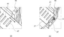
도 9의 (a)는 도 8의 "A"부 확대도이고, 도 9의 (b)는 도 9의 (a)의 요부 종단면도,
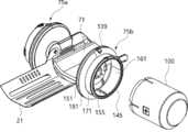
도 10은 도 1의 제3지지부와 제2거치대의 요부 분해 사시도,
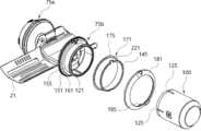
도 11은 도 1의 제3지지부와 구동모터의 분해 사시도,
도 12는 도 1의 제3지지부와 구동모터가 조립된 상태에서의 횡단면도,
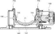
도 13은 도 1의 제3지지부와 구동모터가 조립된 상태에서의 종단면도,
도 14는 도 1의 제3지지부의 제2브래킷의 분해사시도,
도 15는 도 14의 요부 확대도,
도 16은 도 13의 제2브래킷에 부시가 조립된 상태를 도시한 도면,
도 17은 도 16의 제2브래킷에 보조커버가 조립된 상태를 도시한 도면,
도 18은 도 17의 요부 확대 종단면도,
도 19의 (a)는 제1커버의 사시도이고, 도 19의 (b)는 제1커버의 배면 사시도,
도 20의 (a)는 제2커버의 사시도이고, 도 20의 (b)는 제2커버의 배면 사시도,
도 21는 도 1의 제1브래킷과 제2커버가 분리된 상태를 도시한 도면,
도 22는 일 실시예로서 구동모터가 제2브래킷에 장착된 상태를 도시한 도면,
도 23은 일 실시예로서 구동모터가 제1브래킷에 장착된 상태를 도시한 도면,
도 24는 본 발명의 일 실시예에 따른 재활 운동 장치의 제2브래킷과 스토퍼의 요부 분해 사시도,
도 25는 본 발명의 일 실시예에 따른 재활 운동 장치의 제2거치대와 제3거치대가 각도 조절된 상태를 도시한 도면,
도 26은 스토퍼의 다른 실시예를 도시한 도면,
도 27은 도 26의 포스트의 요부 확대 단면도,
도 28은 도 26의 스토퍼를 이용한 재활 운동 장치의 다른 실시예를 도시한 도면,
도 29는 도 7의 제2거치대와 트랙의 조립 상태를 도시한 종단면도이다.1 is a perspective view of a rehabilitation exercise device according to an embodiment of the present invention,
Figure 2 is a plan view of Figure 1,
Figure 3 is a left side view of Figure 1,
Figure 4 is a front view of Figure 1,
Figure 5 is a rear view of Figure 1,
6 is an exploded perspective view of FIG. 1,
7 is a view showing a state in which the seating portion of FIG. 1 is separated;
FIG. 8 is a view showing a state in which the intervals are adjusted so that the second cradle and the track of FIG. 7 approach each other;
Figure 9 (a) is an enlarged view of the "A" part of Figure 8, Figure 9 (b) is a longitudinal sectional view of the main part of Figure 9 (a),
10 is an exploded perspective view of main parts of the third support portion and the second cradle of FIG. 1;
11 is an exploded perspective view of a third support part and a driving motor of FIG. 1;
12 is a cross-sectional view in a state in which the third support part of FIG. 1 and the driving motor are assembled;
13 is a longitudinal sectional view in a state in which the third support part of FIG. 1 and the driving motor are assembled;
14 is an exploded perspective view of the second bracket of the third support portion of FIG. 1;
15 is an enlarged view of a main part of FIG. 14;
16 is a view showing a state in which a bush is assembled to the second bracket of FIG. 13;
17 is a view showing a state in which the auxiliary cover is assembled to the second bracket of FIG. 16;
18 is an enlarged longitudinal sectional view of the main part of FIG. 17;
Figure 19 (a) is a perspective view of the first cover, Figure 19 (b) is a rear perspective view of the first cover,
Figure 20 (a) is a perspective view of the second cover, Figure 20 (b) is a rear perspective view of the second cover,
21 is a view showing a state in which the first bracket and the second cover of FIG. 1 are separated;
22 is a view showing a state in which a driving motor is mounted on a second bracket as an embodiment;
23 is a view showing a state in which a driving motor is mounted on a first bracket as an embodiment;
24 is an exploded perspective view of main parts of a second bracket and a stopper of the rehabilitation exercise device according to an embodiment of the present invention;
25 is a view showing a state in which the second cradle and the third cradle of the rehabilitation exercise device according to an embodiment of the present invention are angle-adjusted;
26 is a view showing another embodiment of a stopper;
27 is an enlarged cross-sectional view of a main part of the post of FIG.
28 is a view showing another embodiment of the rehabilitation exercise device using the stopper of FIG. 26;
29 is a longitudinal sectional view showing an assembled state of the second cradle and the track of FIG. 7;
본 발명의 이점 및 특징, 그리고 그것들을 달성하는 방법은 첨부되는 도면과 함께 상세하게 후술되어 있는 실시예들을 참조하면 명확해질 것이다. 그러나, 본 발명은 이하에서 개시되는 실시예들에 제한되는 것이 아니라 서로 다른 다양한 형태로 구현될 수 있으며, 단지 본 실시예들은 본 발명의 개시가 완전하도록 하고, 본 발명이 속하는 기술 분야의 통상의 기술자에게 본 발명의 범주를 완전하게 알려주기 위해 제공되는 것이며, 본 발명은 청구항의 범주에 의해 정의될 뿐이다.Advantages and features of the present invention, and a method of achieving them will become apparent with reference to the embodiments described below in detail together with the accompanying drawings. However, the present invention is not limited to the embodiments disclosed below, but may be implemented in a variety of different forms. It is provided to fully inform the skilled person of the scope of the present invention, and the present invention is only defined by the scope of the claims.
본 명세서에서 사용된 용어는 실시예들을 설명하기 위한 것이며 본 발명을 제한하고자 하는 것은 아니다. 본 명세서에서, 단수형은 문구에서 특별히 언급하지 않는 한 복수형도 포함한다. 명세서에서 사용되는 "포함한다(comprises)" 및/또는 "포함하는(comprising)"은 언급된 구성요소 외에 하나 이상의 다른 구성요소의 존재 또는 추가를 배제하지 않는다. 명세서 전체에 걸쳐 동일한 도면 부호는 동일한 구성 요소를 지칭하며, "및/또는"은 언급된 구성요소들의 각각 및 하나 이상의 모든 조합을 포함한다. 비록 "제1", "제2" 등이 다양한 구성요소들을 서술하기 위해서 사용되나, 이들 구성요소들은 이들 용어에 의해 제한되지 않음은 물론이다. 이들 용어들은 단지 하나의 구성요소를 다른 구성요소와 구별하기 위하여 사용하는 것이다. 따라서, 이하에서 언급되는 제1 구성요소는 본 발명의 기술적 사상 내에서 제2 구성요소일 수도 있음은 물론이다.The terms used in the present specification are for describing exemplary embodiments and are not intended to limit the present invention. In this specification, the singular form also includes the plural form unless specifically stated in the phrase. As used herein, “comprises” and/or “comprising” do not exclude the presence or addition of one or more other elements other than the mentioned elements. Throughout the specification, the same reference numerals refer to the same elements, and "and/or" includes each and all combinations of one or more of the mentioned elements. Although "first", "second", and the like are used to describe various elements, it goes without saying that these elements are not limited by these terms. These terms are only used to distinguish one component from another component. Therefore, it goes without saying that the first component mentioned below may be the second component within the technical idea of the present invention.
다른 정의가 없다면, 본 명세서에서 사용되는 모든 용어(기술 및 과학적 용어를 포함)는 본 발명이 속하는 기술 분야의 통상의 기술자에게 공통적으로 이해될 수 있는 의미로 사용될 수 있을 것이다. 또한, 일반적으로 사용되는 사전에 정의되어 있는 용어들은 명백하게 특별히 정의되어 있지 않는 한 이상적으로 또는 과도하게 해석되지 않는다.Unless otherwise defined, all terms (including technical and scientific terms) used in the present specification may be used with meanings that can be commonly understood by those of ordinary skill in the art to which the present invention belongs. In addition, terms defined in a commonly used dictionary are not interpreted ideally or excessively unless explicitly defined specifically.
이하, 첨부 도면을 참조하여 본 발명에 대해 상세히 설명한다.Hereinafter, the present invention will be described in detail with reference to the accompanying drawings.
도 1 내지 도 24에는 본 발명의 일 실시예에 따른 재활 운동 장치가 도시되어 있다.1 to 24 illustrate a rehabilitation exercise device according to an embodiment of the present invention.
이들 도면에 도시된 바와 같이, 본 발명의 일 실시예에 따른 재활 운동 장치(1)는 크게, 손 또는 발을 지지하는 제1지지부(10)와, 상지의 전완 또는 하지의 하퇴를 제2지지부(20)와, 제1지지부(10)와 제2지지부(20)를 연결하는 커넥터(30)와, 상지의 상완 또는 하지의 대퇴를 지지하는 제3지지부(70)를 포함할 수 있다.As shown in these figures, the
이하에서는 설명의 편리상, 본 발명의 일 실시예에 따른 재활 운동 장치(1)가 상지에 착용하여 재활 운동하는 것에 대해 설명한다. 한편, 본 발명의 일 실시예에 따른 재활 운동 장치(1)는 상지 이외에 하지에 착용하여 재활 운동할 수도 있다.Hereinafter, for convenience of description, a description will be given of the
제1지지부(10)는 제1거치대(11)와, 한 쌍의 제1암(15)을 포함한다.The
제1거치대(11)는 손의 손등 또는 손바닥을 부분적으로 둘러싸도록 만곡되게 함몰 형성된다. 이로써, 사용자는 재활 운동시 손을 제1거치대(11)에 안정적으로 거치할 수 있게 된다. 여기서, 제1거치대(11)에 밴드 또는 별도의 케이스를 마련하여, 손이 제1거치대(11)로부터 이탈하지 않도록 고정할 수도 있다.The
한 쌍의 제1암(15)은 손을 사이에 두고 예컨대, 제1거치대(11)를 사이에 두고, 제2지지부(20)를 향하는 제1거치대(11)의 양측 단부에 각각 상호 대향하게 편지지된다. 한 쌍의 제1암(15)은 후술할 커넥터(30)의 한 쌍의 제1브래킷(65a,65b)에 선회가능하게 결합된다. 예컨대, 각 제1암(15)의 자유단부는 볼트, 결합핀 등과 같은 결합수단(미도시)에 의해 각 제1브래킷(65a,65b)에 마련된 구동축(155)에 결합되어, 구동축(155)이 정역회전함에 따라 구동축(155)을 중심으로 상하방향으로 선회하게 된다.The pair of
제2지지부(20)는 제2거치대(21)와, 한 쌍의 제2암(25)을 포함한다.The
제2거치대(21)는 전완을 부분적으로 둘러싸도록 만곡되게 함몰 형성된다. 이로써, 사용자는 재활 운동시 전완을 제2거치대(21)에 안정적으로 거치할 수 있게 된다. 여기서, 제2거치대(21)에 밴드 또는 별도의 케이스를 마련하여, 전완이 제2거치대(21)로부터 이탈하지 않도록 고정할 수도 있다.The
한 쌍의 제2암(25)은 전완을 사이에 두고 예컨대, 제2거치대(21)를 사이에 두고, 제3지지부(70)를 향하는 제2거치대(21)의 양측 단부에 각각 상호 대향하게 편지지된다. 한 쌍의 제2암(25)은 후술할 제3지지부(70)의 한 쌍의 제2브래킷(75a,75b)에 선회가능하게 결합된다. 각 제2암(25)의 자유단부는 볼트, 결합핀 등과 같은 결합수단에 의해 각 제2브래킷(75a,75b)에 마련된 구동축(155)에 결합되어, 구동축(155)이 정역회전함에 따라 구동축(155)을 중심으로 상하방향으로 선회하게 된다.The pair of
커넥터(30)는 제1거치대(11)와 제2거치대(21) 사이에 배치되며, 트랙(31)과 한 쌍의 제1브래킷(65a,65b)을 포함한다.The
트랙(31)은 제2거치대(21)에 대응하는 단면형상을 가지며, 제2거치대(21)의 하부 영역에 배치된다. 트랙(31)은 제2거치대(21)와 적어도 부분적으로 중첩가능하게 제2거치대(21)의 길이방향을 따라 배치된다. 이에 따라, 트랙(31)은 제2거치대(21)의 길이방향을 따라 왕복이동할 수 있다.The
또한, 트랙(31)은 도 7에 도시된 바와 같이, 제2거치대(21)와 클램프(33)에 의해 상호 연결된다. 클램프(33)는 제2거치대(21)의 상부면에 배치되는 클램핑 플레이트(35)와, 클램핑 플레이트(35)를 지지하며 트랙(31)에 지지되는 클램핑 볼트(37)를 포함한다.In addition, the
한편, 제2거치대(21)에는 가이드공(23)이 형성되어 있다. 가이드공(23)은 제2거치대(21)에 제2거치대(21)의 길이방향을 따라 예컨대, 복수의 슬릿(41)과 나란하게 일정 길이로 관통 형성된 장공 형상을 가진다. 가이드공(23)에는 제2거치대(21)와 트랙(31)을 상호 연결하는 클램프(33)가 이동가능하게 결합된다.Meanwhile, a
이에 따라, 제2거치대(21)와 트랙(31)이 상호 접근 또는 이격할 때, 가이드공(23)은 제2거치대(21)와 트랙(31)의 이동을 가이드할 수 있게 된다.Accordingly, when the
또한, 도 29에 도시된 바와 같이, 트랙(31)의 일측 가장자리에는 트랙용 가이드(39)가 마련되어 있다.In addition, as shown in FIG. 29, a
트랙용 가이드(39)는 제2거치대(21)의 일측 가장자리를 부분적으로 둘러싸며, 제2거치대(21)가 트랙(31)을 따라 왕복이동할 때 제2거치대(21)의 일측 가장자리를 슬라이딩가능하게 지지한다.The
이와 같이, 트랙용 가이드(39)를 마련함으로써, 제2거치대(21)와 트랙(31)이 상호 접근 또는 이격할 때, 제2거치대(21)와 트랙(31)의 이동을 가이드할 뿐만 아니라 제2거치대(21)와 트랙(31)은 분리되지 않으며 안정적으로 상호 접근 또는 이격할 수 있게 된다.In this way, by providing the
여기서, 트랙용 가이드(39)는 트랙(31)의 양측 가장자리를 따라 마련될 수도 있다.Here, the
한편, 제1거치대(11)와 제2거치대(21)는 간격 조절부(41,45,51)에 의해 간격 조절될 수 있다.Meanwhile, the
간격 조절부(41,45,51)는 도 8 및 도 9에 도시된 바와 같이, 복수의 슬릿(41)과, 푸시버튼(45)과, 탄성부재(51)를 포함한다.As shown in FIGS. 8 and 9, the
복수의 슬릿(41)은 제2거치대(21)에 제2거치대(21)의 길이방향을 따라 일정 간격으로 관통 형성되어 있다.The plurality of
푸시버튼(45)은 복수의 슬릿(41)에 선택적으로 결합되는 결합돌기(47)를 가진다. 푸시버튼(45)은 트랙(31)에 승강가능하게 마련되어, 누름 동작시 슬릿(41)과 결합돌기(47)의 결합상태를 해제시킨다.The
탄성부재(51)는 푸시버튼(45)과 트랙(31) 사이에 마련되어 푸시버튼(45)을 탄성 지지한다. 탄성부재(51)는 결합돌기(47)가 슬릿(41)에 결합상태를 유지하도록 푸시버튼(45)에 탄성력을 제공한다.The
이와 같이, 푸시버튼(45)의 결합돌기(47)를 제2거치대(21)의 복수의 슬릿(41)에 선택적으로 결합함으로써, 사용자의 다양한 전완의 길이에 대응하며 제1거치대(11)와 제2거치대(21)의 간격을 조절하여, 재활 운동을 할 수 있게 된다.In this way, by selectively coupling the
한편, 트랙(31)과 제2거치대(21)의 상부에는, 사용자의 전완이 불편없이 안착되도록 전완이 안착되는 안착부(55)가 착탈된다. 안착부(55)는 제2거치대(21)에 대응하는 단면형상을 가진다.On the other hand, on the upper part of the
한 쌍의 제1브래킷(65a,65b)은 제1지지부(10)의 한 쌍의 제1암(15)을 사이에 두고, 트랙(31)의 양측에 각각 상호 대향하게 배치된다.The pair of
이하에서는 설명의 편리상, 제1지지부(10)에서 제2지지부(20)를 볼 때, 좌측에 위치하는 제1브래킷을 레프트 제1브래킷(65a)이라 하고, 우측에 위치하는 제1브래킷을 라이트 제1브래킷(65b)이라고 한다.Hereinafter, for convenience of explanation, when viewing the
제1브래킷(65a,65b)에는 제1지지부(10)의 제1암(15)이 볼트, 결합핀 등과 같은 결합수단(미도시)에 의해 결합된다.The
한편, 제1브래킷(65a,65b)은 후술할 제2브래킷(75a,75b)과 동일한 구성 및 형상을 가지며, 이에 제1브래킷(65a,65b)의 구체적인 설명에 대해서는 후술할 제2브래킷(75a,75b)에서 설명하기로 한다.On the other hand, the first bracket (65a, 65b) has the same configuration and shape as the second bracket (75a, 75b) to be described later, according to the detailed description of the first bracket (65a, 65b), the second bracket (75a) to be described later. ,75b).
제3지지부(70)는 제3거치대(71)와, 한 쌍의 제2브래킷(75a,75b)을 포함한다.The
제3거치대(71)는 상완을 부분적으로 둘러싸도록 만곡되게 함몰 형성된다. 이로써, 사용자는 재활 운동시 상완을 제3거치대(71)에 안정적으로 거치할 수 있게 된다. 여기서, 제3거치대(71)에 밴드 또는 별도의 케이스를 마련하여, 상완이 제3거치대(71)로부터 이탈하지 않도록 고정할 수도 있다.The
한 쌍의 제2브래킷(75a,75b)은 전술한 제1지지부(10)의 제1브래킷(65a,65b)과 동일한 구성을 가진다. 따라서, 본 발명의 설명에서는 제1브래킷(65a,65b)과 제2브래킷(75a,75b)을 구성하는 각 구성요소의 명칭과 참조부호를 동일하게 적용하고, 대표적으로 제2브래킷(75a,75b)을 인용하여 브래킷의 각 구성요소와 기능에 대해 설명한다.The pair of
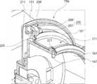
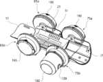
한 쌍의 제2브래킷(75a,75b)은 도 10 내지 도 18에 도시된 바와 같이, 휠(151)과, 구동모터 삽입부(161)와, 부시(171)를 포함한다.The pair of
휠(151)은 원형의 바퀴 형상을 가진다. 휠(151)의 중심에는 구동축(155)이 회전가능하게 마련된다.The
구동축(155)에는 후술할 구동모터(100)의 모터축(105)이 선택적으로 결합될 수 있다. 또한, 구동축(155)에는 제2지지부(20)의 제2암(25)이 볼트, 결합핀 등과 같은 결합수단(미도시)에 의해 결합된다. 휠(151)의 외측을 향하는 구동축(155)의 일측에는 구동모터(100)의 모터축(105)이 결합되고, 휠(151)의 내측을 향하는 구동축(155)의 타측에는 제2암(25)이 결합된다. 구동모터(100)가 제2브래킷(75a,75b)에 결합되면, 구동모터(100)가 정역회전함에 따라 제2지지부(20)의 한 쌍의 제2암(25)은 구동축(155)을 중심으로 상하방향으로 선회함과 동시에, 제2거치대(21)도 상하방향으로 선회하게 된다. 따라서, 제2거치대(21)에 전완이 거치된 경우, 제2거치대(21)가 선회함에 따라 팔꿈치 관절을 운동할 수 있게 된다.The
한편, 한 쌍의 제2브래킷(75a,75b)에 각각 마련되는 한 쌍의 구동축(155)은, 제2거치대(21)의 저부 영역을 가로지르며 한 쌍의 제2브래킷(75a,75b)을 향해 연장 형성되어, 각 구동축(155)에 지지되는 링크(157)에 의해 상호 연결된다. 이로써, 한 쌍의 제2브래킷(75a,75b)의 회전은 동기화될 수 있다.On the other hand, a pair of
그리고, 한 쌍의 제2브래킷(75a,75b)은 후술할 스토퍼(220)에 의해 받침대(241)에 된다. 여기서, 다른 실시예로서, 한 쌍의 제2브래킷(75a,75b)의 각 휠(151)은 받침대(241)에 직접 지지될 수도 있다.Then, the pair of
한편, 제2브래킷(75a,75b)과 동일한 구성을 갖는 제1브래킷(65a,65b)의 휠(151)의 중심에 회전가능하게 마련된 구동축(155)에는 구동모터(100)의 모터축(105)이 선택적으로 결합될 수 있고, 제1지지부(10)의 제1암(15)이 볼트, 결합핀 등과 같은 결합수단(미도시)에 의해 결합된다. 휠(151)의 외측을 향하는 구동축(155)의 일측에는 구동모터(100)의 모터축(105)이 결합될 수 있고, 휠(151)의 내측을 향하는 구동축(155)의 타측에는 제1암(15)이 결합된다. 구동모터(100)가 제1브래킷(65a,65b)에 결합되면, 구동모터(100)가 정역회전함에 따라 제1지지부(10)의 한 쌍의 제1암(15)은 구동축(155)을 중심으로 상하방향으로 선회함과 동시에, 제1거치대(11)도 상하방향으로 선회하게 된다. 따라서, 제1거치대(11)에 손이 거치된 경우, 제1거치대(11)가 선회함에 따라 손목 관절을 운동할 수 있게 된다.Meanwhile, the
한편, 한 쌍의 제1브래킷(65a,65b)에 각각 마련되는 한 쌍의 구동축(155)은, 트랙(31)의 저부 영역을 가로지르며 한 쌍의 제1브래킷(65a,65b)을 향해 연장 형성되어 각 구동축(155)에 지지되는 링크(157)에 의해 상호 연결된다. 이로써, 한 쌍의 제1브래킷(65a,65b)의 회전은 동기화될 수 있다.On the other hand, a pair of
그리고, 한 쌍의 제1브래킷(65a,65b)의 각 휠(151)은 받침대(241)에 지지될 수 있다.In addition, each
구동모터 삽입부(161)는 일정 폭의 링 형상을 가지며, 휠(151)의 외측에 돌출되게 마련된다. 구동모터 삽입부(161)에는 구동모터(100)가 장착된다.The drive
부시(171)는 링 형상을 가지며, 구동모터 삽입부(161)의 외주에 슬라이딩 가능하게 결합된다. 부시(171)는 구동모터 삽입부(161)의 외경과 동일한 크기의 내경을 가진다. 이에 따라, 부시(171)는 휠(151)과 구동모터 삽입부(161)에 대해 상대 회전할 수 있게 된다. 여기서, 부시(171)는 금속 재질로 이루어질 수 있다.The
또한, 휠(151)을 향하는 부시(171)의 일측 단부에는, 부시(171)의 외주를 따라 일정의 폭으로 절곡 연장된 플랜지(175)가 마련되어 있다.In addition, at one end of the
부시(171)의 플랜지(175)는 외부로 노출되지 않도록 보조커버(181)에 의해 커버된다. 보조커버(181)에는 부시(171)가 관통하며, 보조커버(181)의 내측에는 휠(151)을 향해 후크 돌기(185)가 돌출 형성되어 있다. 이에 따라, 보조커버(181)의 후크 돌기(185)가 휠(151)에 후크 결합되어, 보조커버(181)는 부시(171)의 플랜지(175)를 감싸며 휠(151)에 고정된다.The
한편, 플랜지(175)의 일 영역에는, 복수의 각도 조절공(201)이 부시(171)의 원주방향을 따라 일정 각도의 간격으로 형성될 수 있다. 복수의 각도 조절공(201)에 대해서는 후술하기로 한다.Meanwhile, in one region of the
또한, 본 발명의 일 실시예에 따른 재활 운동 장치(1)는 제1거치대(11) 또는 제2거치대(21)를 선택적으로 선회시키기 위한 구동모터(100)를 포함한다.In addition, the
구동모터(100)는 한 쌍의 제1브래킷(65a,65b), 한 쌍 제2브래킷(75a,75b) 중 어느 하나의 브래킷에 선택적으로 착탈가능하게 결합되어, 제1거치대(11) 또는 제2거치대(21)를 선회시킨다.The driving
구동모터(100)는 도 11 및 도 12에 도시된 바와 같이, 외관을 형성하는 모터하우징(101)과, 모터하우징(101)에 수용되는 고정자(103)와, 모터하우징(101)의 중심축선을 따라 마련되어 고정자(103)와 전자기적 작용에 의해 회전하는 회전자(107)가 장착된 모터축(105)을 포함한다.As shown in FIGS. 11 and 12, the driving
한편, 구동모터(100)에서 발생하는 회전력을 브래킷으로 전달하기 위한 전달수단으로서, 도 10 및 도 11에 도시된 바와 같이, 복수의 구동 핀(111)과, 복수의 핀 삽입홈(115)을 포함한다.On the other hand, as a transmission means for transmitting the rotational force generated from the
복수의 구동 핀(111)은 구동모터(100)의 모터축(105)으로부터 일정 길이로 돌출 형성된다. 복수의 구동 핀(111)은 모터축(105)의 회전중심의 둘레를 따라 마련된다.The plurality of driving
복수의 핀 삽입홈(115)은 모터축(105)의 복수의 구동 핀(111)에 대응하며 제1브래킷(65a,65b) 및 제2브래킷(75a,75b)의 각 구동축(155)에 함몰 형성되어, 복수의 구동 핀(111)이 삽입 결합된다.The plurality of
이와 같이, 구동모터(100)의 모터축(105)과 각 브래킷(65a,65b,75a,75b)의 구동축(155)이 복수의 구동 핀(111)과 복수의 핀 삽입홈(115)에 의해 상호 결합됨에 따라, 모터축(105)과 구동축(155) 사이에는 슬립이 발생하지 않게 되어, 구동모터(100)의 회전력은 모터축(105)을 거쳐, 구동모터(100)가 장착된 브래킷의 구동축(155)으로 안정적으로 전달된다.In this way, the
또한, 본 발명의 일 실시예에 따른 재활 운동 장치(1)는 구동모터(100)를 제1브래킷(65a,65b) 또는 제2브래킷(75a,75b)에 장착하는 것을 안내하는 모터 장착 가이드부(120)를 포함한다.In addition, the
모터 장착 가이드부(120)는 도 10 및 도 11에 도시된 바와 같이, 복수의 가이드 리브(121)와, 복수의 가이드 리브 홈(125)을 포함한다.The motor mounting
복수의 가이드 리브(121)는 각 브래킷(65a,65b,75a,75b)의 구동모터 삽입부(161)의 내주에 원주방향을 따라 간격을 두고, 구동모터 삽입부(161)의 자유단부로부터 구동모터(100)의 장착방향으로 일정 길이로 돌출 형성된다.The plurality of
복수의 가이드 리브 홈(125)은 복수의 가이드 리브(121)에 대응하여, 구동모터(100)의 외주에 일정 깊이로 함몰 형성되어 각 가이드 리브(121)가 끼움 결합된다.The plurality of
이로써, 가이드 리브(121)와 가이드 리브 홈(125)은 구동모터(100)가 선택된 브래킷에 장착될 때 가이드함과 동시에, 선택된 브래킷에 장착된 구동모터(100)가 구동모터 삽입부(161)의 원주방향을 따라 요동하는 것을 방지할 수 있게 된다.Accordingly, the
또한, 본 발명의 일 실시예에 따른 재활 운동 장치(1)는 제1브래킷(65a,65b) 및 제2브래킷(75a,75b)에 구동모터(100)를 장착하기 위한 모터 장착수단(130)을 포함한다.In addition, the
모터 장착수단(130)은 도 10 내지 도 12에 도시된 바와 같이, 후크 결합부(131)와, 모터 착탈 스위치(133)와, 탄성부재(141)를 포함한다.The motor mounting means 130 includes a
후크 결합부(131)는 제1브래킷(65a,65b) 및 제2브래킷(75a,75b)의 휠(151)에 함몰 형성되어 있다.The
모터 착탈 스위치(133)는 구동모터(100)로부터 돌출되어 후크 결합부(131)에 착탈가능하게 후크 결합되는 후크(135)와, 후크(135)를 지지하며 모터하우징(101)의 내부에 형성된 경로를 따라 길이 연장된 후크 브릿지(137)와, 후크 브릿지(137)를 지지하며 구동모터(100)로부터 노출되게 마련된 모터 착탈 버튼(139)을 포함한다. 모터 착탈 버튼(139)은 누름 동작시 후크 결합부(131)와 후크(135)의 결합상태를 해제시킨다.The motor attachment/
탄성부재(141)는 모터하우징(101)에 마련되어 모터 착탈 버튼(139)을 탄성 지지한다. 탄성부재(141)는 후크(135)가 후크 결합부(131)에 결합상태를 유지하도록 모터 착탈 버튼(139)에 탄성력을 제공한다.The
이와 같이, 모터 착탈 스위치(133)를 동작시킴에 따라, 구동모터(100)의 후크(135)를 선택된 브래킷의 후크 결합부(131)에 후크 결합 또는 후크 결합해제함으로써, 구동모터(100)의 착탈이 용이하여 사용자의 편의성을 향상시키고, 구동모터(100)가 모터축(105)의 축방향을 따라 구동모터 삽입부(161)로부터 분리되는 것을 방지하며, 선택된 브래킷에 견고하게 장착될 수 있게 된다.In this way, as the motor attaching/detaching
또한, 모터 장착수단(130)은 구동모터 링(145)을 더 포함한다.In addition, the motor mounting means 130 further includes a
구동모터 링(145)은 링 형상을 가지며, 부시(171)에 결합된다. 구동모터 링(145)의 내주에는 원주방향을 따라 복수의 부시결합돌기(147, 도 18 참조)가 간격을 두고 돌출 형성되어 있다. 부시결합돌기(147)는 부시(171)의 외주에 원주방향을 따라 일정 간격 및 일정 길이로 함몰 형성된 복수의 부시홈(177, 도 15참조)에 끼움 결합된다.The
이로써, 구동모터(100)를 선택된 브래킷에 장착할 때, 구동모터(100)의 모터하우징(101)을 구동모터 삽입부(161)에 장착하기에 앞서, 구동모터 링(145)의 부시결합돌기(147)를 부시(171)의 부시홈(177)에 끼움 결합함으로써, 구동모터 링(145)은 부시(171)에 지지됨과 동시에, 구동모터(100)에 지지된다. 이러한 구동모터 링(145)은 후술할 스토퍼 링(225)이 부시(171)로부터 이탈하는 것을 방지하는 역할도 한다.Accordingly, when mounting the
따라서, 구동모터(100)의 가이드 리브 홈(125)이 구동모터 삽입부(161)에 형성된 가이드 리브(121)에 끼움 결합되어 구동모터(100)가 구동모터 삽입부(161)에 지지되고, 또한 구동모터(100)의 후크(135)가 휠(151)의 후크 결합부(131)에 후크 결합되어 구동모터(100)가 휠(151)에 지지되며, 구동모터 링(145)의 부시결합돌기(147)가 부시(171)의 부시홈(177)에 끼움 결합되어 구동모터 링(145)은 구동모터(100)에 의해 지지됨과 동시에 부시(171)에 지지된다.Accordingly, the
또한, 본 발명의 일 실시예에 따른 재활 운동 장치(1)는 도 19 및 도 20에 도시된 바와 같이, 구동모터(100)가 장착되는 브래킷을 제외한 나머지 브래킷에 장착되어 커버하는 제1커버(190)와 제2커버(195)를 포함한다.In addition, the
제1커버(190)와 제2커버(195)는 부시(171)에 장착된다.The
제1커버(190)의 일단부 둘레에는 도 19에 도시된 바와 같이, 부시(171)의 복수의 부시홈(177)에 끼움 결합되는 복수의 제1커버돌기(191)가 간격을 두고 돌출 형성되어 있다.As shown in FIG. 19, a plurality of
제1커버(190)의 제1커버돌기(191)가 부시(171)의 부시홈(177)에 끼움 결합됨에 따라, 제1커버(190)는 부시(171)에 장착된다.As the
이러한 제1커버(190)는, 구동모터(100)의 회전력에 의해 회전하는 구동축(155)을 가지며 구동모터(100)가 장착되지 않는 브래킷의 부시(171)에 결합되어, 해당 구동축(155)의 회전을 저지하지 않으며 브래킷의 구동축(155) 등이 외부로 노출되지 않도록 커버한다.This
제2커버(195)의 일단부 둘레에는 도 20에 도시된 바와 같이, 부시(171)의 복수의 부시홈(177)에 끼움 결합되는 복수의 제2커버돌기(197)가 간격을 두고 돌출 형성되어 있다.Around one end of the
또한, 제2커버(195)의 일측 판면에는, 구동축(155)의 복수의 핀 삽입홈(115)에 삽입 결합되는 복수의 커버 핀(199)이 마련되어 있다. 복수의 커버 핀(199)은 구동축(155)의 회전중심의 둘레를 따라 함몰 형성된다. 복수의 커버 핀(199)은 한 쌍의 제1브래킷(65a,65b) 및 한 쌍의 제2브래킷(75a,75b)의 각 구동축(155) 중 구동모터(100)와 연계하여 회전하지 않고 자전하는 구동축(155)의 핀 삽입홈(115)에 삽입 결합된다.In addition, a plurality of cover pins 199 that are inserted and coupled to the plurality of
제2커버(195)의 제2커버돌기(197)가 부시(171)의 부시홈(177)에 끼움 결합됨과 동시에, 복수의 커버 핀(199)이 구동축(155)의 핀 삽입홈(115)에 삽입 결합됨에 따라, 제2커버(195)는 부시(171)와 구동축(155)에 동시에 장착된다.The
이러한 제2커버(195)는, 구동모터(100)와 연계하여 회전하지 않는 구동축(155)을 가지는 브래킷의 부시(171)와 구동축(155)에 동시에 결합되어, 해당 구동축(155)의 회전을 제한한다. 이로써, 제2커버(195)가 결합된 브래킷의 구동축(155)에 연결된 암의 선회 운동을 제한하여, 해당 암에 연결된 거치대의 선회 운동을 제한한다.This
한편, 본 실시예에서의 재활 운동 장치(1)는 도 22에 도시된 바와 같이. 구동모터(100)가 라이트 제2브래킷(75b)에 장착되고, 제1커버(190)가 레프트 제2브래킷(75a)에 장착되며, 제2커버(195)가 한 쌍의 제1브래킷(65a,65b)에 장착되는 구성을 가진다.On the other hand, as shown in Figure 22, the
도 21에는 제1브래킷(65a,65b)과 제2커버(195)가 분리된 상태를 도시한 도면이 도시되어 있다.21 is a diagram showing a state in which the
이로써, 도 22에 도시된 바와 같이. 라이트 제2브래킷(75b)에 구동모터(100)를 장착하고, 레프트 제2브래킷(75a)에 제1커버(190)를 장착하며, 한 쌍의 제1브래킷(65a,65b)에는 각각 제2커버(195)를 장착한 경우, 제2거치대(21)는 구동모터(100)의 회전력에 의해 선회 운동을 할 수 있지만, 제1거치대(11)는 제2커버(195)에 의해 선회 운동이 제한되어, 사용자는 손목 관절이 움직이지 않은 상태에서 팔꿈치 관절을 운동할 수 있게 된다.Thus, as shown in Fig. 22. The driving
또한, 다른 실시예로서, 도 23에 도시된 바와 같이. 라이트 제1브래킷(65a,65b)에 구동모터(100)를 장착하고, 레프트 제1브래킷(65a,65b)에 제1커버(190)를 장착하며, 한 쌍의 제2브래킷(75a,75b)에는 각각 제2커버(195)를 장착한 경우, 제1거치대(11)는 구동모터(100)의 회전력에 의해 선회 운동을 할 수 있지만, 제2거치대(21)는 제2커버(195)에 의해 선회 운동이 제한되어, 사용자는 팔꿈치 관절이 움직이지 않은 상태에서 손목 관절을 운동할 수 있게 된다.Further, as another embodiment, as shown in FIG. 23. The driving
이와 같이, 제1커버(190)와 제2커버(195)를 구동모터(100)에 의해 선회하는 관절 부위와, 구동모터(100)에 의해 선회하지 않는 관절 부위를 구별하여 해당 브래킷에 장착하여 안정적으로 재활 운동할 수 있게 된다.In this way, the
한편, 본 발명의 일 실시예에 따른 재활 운동 장치(1)는, 운동하고자 하는 상지 위치에 대응하여, 구동모터(100)를 선택된 브래킷에 장착하여 운동할 수 있다.Meanwhile, the
예컨대, 구동모터(100)가 레프트 제1브래킷(65a) 또는 레프트 제2브래킷(75a)에 장착되는 경우, 본 발명의 일 실시예에 따른 재활 운동 장치(1)는 구동모터(100)가 사용자의 몸통과 간섭하지 않으며, 오른쪽 상지에 착용하여 운동할 수 있게 된다. 이 때, 구동모터(100)가 레프트 제1브래킷(65a)에 장착되면 오른쪽 손목 관절을 운동할 수 있게 되고, 구동모터(100)가 레프트 제2브래킷(75a)에 장착되면 오른쪽 팔꿈치 관절을 운동할 수 있게 된다.For example, when the driving
구동모터(100)가 라이트 제1브래킷(65b) 또는 라이트 제2브래킷(75b)에 장착되는 경우, 본 발명의 일 실시예에 따른 재활 운동 장치(1)는 구동모터(100)가 사용자의 몸통과 간섭하지 않으며, 왼쪽 상지에 착용하여 운동할 수 있게 된다. 이 때, 구동모터(100)가 라이트 제1브래킷(65b)에 장착되면 왼쪽 손목 관절을 운동할 수 있게 되고, 구동모터(100)가 레프트 제2브래킷(75a)에 장착되면 왼쪽 팔꿈치 관절을 운동할 수 있게 된다.When the
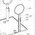
또한, 본 발명의 일 실시예에 따른 재활 운동 장치(1)는 제2거치대(21)와 제3거치대(71) 사이의 각도를 조절하는 각도 조절부(200)를 포함할 수 있다.In addition, the
각도 조절부(200)는 도 14 내지 도 18에 도시된 바와 같이, 복수의 각도 조절공(201)과, 각도 조절 스위치(205)와, 탄성부재(211)를 포함한다.The
복수의 각도 조절공(201)은 부시(171)의 플랜지(175)에 부시(171)의 원주방향을 따라 일정 각도의 간격으로 형성된다.A plurality of angle adjustment holes 201 are formed at intervals of a predetermined angle along the circumferential direction of the
각도 조절 스위치(205)는 부시(171)의 회전궤적 상에 마련되어 복수의 각도 조절공(201)에 선택적으로 결합되는 로킹돌기(207)와, 로킹돌기(207)를 지지하며 라이트 제2브래킷(75b)의 휠(151)에 승강가능하게 마련되어 누름 동작시 로킹돌기(207)와 각도 조절공(201)의 로킹을 해제시키는 스위치 노브(209)를 포함한다.The
탄성부재(211)는 각도 조절 스위치(205)를 탄성 지지하며, 로킹돌기(207)가 각도 조절공(201)에 로킹상태를 유지하도록 각도 조절 스위치(205)에 탄성력을 제공한다.The
이로써, 각도 조절 스위치(205)를 눌러 로킹돌기(207)를 각도 조절공(201)으로부터 로킹해제하고 나서, 각도 조절 스위치(205)를 누른 상태에서 라이트 제2브래킷(75b)의 휠(151)을 부시(171)에 대해 상대 회전시켜, 제3거치대(71)를 제2거치대(21)에 대해 원하는 각도를 이룬 후, 각도 조절 스위치(205)를 누름 해제하여 로킹 돌기를 선택된 각도 조절공(201)에 로킹시킨다.Accordingly, after pressing the
이와 같이, 로킹돌기(207)를 갖는 부시(171)의 원주 방향을 따라 형성된 복수의 각도 조절공(201)에 선택적으로 결합함으로써, 도 25에 도시된 바와 같이 사용자의 상태에 따른 전완과 상완 사이의 다양한 각도에 대응하며 제2거치대(21)와 제3거치대(71) 사이의 각도를 조절하여 재활 운동할 수 있게 된다.In this way, by selectively coupling to the plurality of angle adjustment holes 201 formed along the circumferential direction of the
또한, 제2거치대(21)와 제3거치대(71)의 각도 조절에 따라, 한 쌍의 제2브래킷(75a,75b)의 부시(171)의 회전을 저지하기 위한 스토퍼(220)를 더 포함할 수 있다.In addition, according to the angle adjustment of the
스토퍼(220)는 스토퍼 홈(221)과, 스토퍼 링(225)과, 포스트(231)를 포함한다.The
스토퍼 홈(221)은 부시(171)의 자유단부로부터 부시(171)의 원주방향에 대해 가로로 일정 폭으로 절취 형성된다.The
스토퍼 링(225)은 부시(171)의 스토퍼 홈(221)에 결합되어 부시(171)의 회전을 저지하는 스토퍼 돌기(227)를 가지며, 부시(171)의 외주에 결합된다.The
한편, 도 24에 도시된 바와 같이 구동모터(100)가 장착되는 라이트 제2브래킷(75b)에 스토퍼 링(225)이 장착되는 경우, 스토퍼 링(225)은 라이트 제2브래킷(75b)에 마련되는 부시(171)의 부시홈(177)에 끼움 결합되는 구동모터 링(145)에 의해 부시(171)로부터 이탈하지 않게 된다.On the other hand, as shown in FIG. 24, when the
또한, 스토퍼 링(225)이 구동모터(100)가 장착되지 않는 레프트 제2브래킷(75a)에 장착되는 경우, 스토퍼 링(225)은 레프트 제2브래킷(75a)에 마련되는 부시(171)의 부시홈(177)에 끼움 결합되는 제1커버(190)와 제2커버(195)에 의해 부시(171)로부터 이탈하지 않게 된다.In addition, when the
포스트(231)는 일정 길이의 봉 형상을 가지며, 일단부는 스토퍼 링(225)을 지지하고, 타단부는 받침대(241)에 지지된다.The
이로써, 제2거치대(21)와 제3거치대(71)는 일 예로서 도 25에 도시된 바와 같이 각도 조절된 후, 제2브래킷(75a,75b)이 스토퍼(220)에 의해 고정되어, 안정적으로 각도를 유지할 수 있게 된다.Accordingly, after the
한편, 포스트(231)는 다른 실시예로서, 도 26 및 도 27에 도시된 바와 같이 상호 중첩되게 결합되는 제1파이프(233)와 제2파이프(235)로 구성된다.Meanwhile, as another embodiment, the
제1파이프(233)와 제2파이프(235)는 상호 접근 및 이격하며 길이 신축되어, 받침대(241)에 대한 스토퍼 링(225)의 높이를 조절한다.The
제1파이프(233)와 제2파이프(235)는 원하는 길이로 길이 조절된 후, 제1파이프(233)와 제2파이프(235)의 외주에 동시에 결합되는 고정 노브(237)의 조임력에 의해 고정된다.After the length of the
이러한 길이 조절이 가능한 포스트(231)를 구비하는 재활 운동 장치(1)는 도 28에 도시된 바와 같이 조립되어, 하지의 운동을 위한 재활 운동 장치(1)로 사용할 수 있게 된다.The
한편, 본 발명의 일 실시예에 따른 재활 운동 장치(1)는 한 쌍의 제1브래킷(65a,65b) 사이에는 손목 관절이 배치되고, 한 쌍의 제2브래킷(75a,75b) 사이에는 팔꿈치 관절이 배치될 수 있다.Meanwhile, in the
또한, 전술한 실시예에서는 본 발명의 일 실시예에 따른 재활 운동 장치(1)가 상지에 한정하여 사용하는 것으로 도시되어 있지만, 하지에도 사용할 수도 있다.In addition, in the above-described embodiment, although the
이 경우, 전술한 실시예의 각 구성요소의 구조와 기능의 설명 중, 상지의 손은 하지의 발에 대응하고, 상지의 손목은 하지의 발목에 대응하며, 상지의 전완은 하지의 하퇴에 대응하며, 상지의 상완은 하지의 대퇴에 대응한다. 이에 따라, 제1거치대(11)와 제2거치대(21)와 제3거치대(71)를 하지의 발, 하퇴, 대퇴에 대응하는 크기의 것으로 모듈화하고 교체 조립하여, 상지 대신에 하지를 거치하여 재활 운동할 수도 있다.In this case, in the description of the structure and function of each component of the above-described embodiment, the hand of the upper limb corresponds to the foot of the lower limb, the wrist of the upper limb corresponds to the ankle of the lower limb, and the forearm of the upper limb corresponds to the lower leg of the lower limb, and , The upper arm of the upper extremity corresponds to the thigh of the lower extremity. Accordingly, the
이상, 첨부된 도면을 참조로 하여 본 발명의 실시예를 설명하였지만, 본 발명이 속하는 기술분야의 통상의 기술자는 본 발명이 그 기술적 사상이나 필수적인 특징을 변경하지 않고서 다른 구체적인 형태로 실시될 수 있다는 것을 이해할 수 있을 것이다. 그러므로, 이상에서 기술한 실시예들은 모든 면에서 예시적인 것이며, 제한적이 아닌 것으로 이해해야만 한다.In the above, embodiments of the present invention have been described with reference to the accompanying drawings, but those of ordinary skill in the art to which the present invention pertains can be implemented in other specific forms without changing the technical spirit or essential features. You will be able to understand. Therefore, the embodiments described above are illustrative in all respects, and should be understood as non-limiting.
1: 상지 및 하지용 재활 운동 장치
10: 제1지지부
11: 제1거치대
20: 제2지지부
21: 제2거치대
30: 커넥터
31: 트랙
41: 슬릿
45: 푸시버튼
65a,65b: 제1브래킷
70: 제3지지부
71: 제3거치대
75a,75b: 제2브래킷
100: 구동모터
111: 구동 핀
115: 핀 삽입홈
120: 모터 장착 가이드부
121: 가이드 리브
125: 가이드 리브 홈
130: 모터 장착수단
131: 후크 결합부
133: 모터 착탈 스위치
135: 후크
141: 탄성부재
145: 구동모터 링
151: 휠
155: 구동축
161: 구동모터 삽입부
171: 부시
177: 부시홈
190: 제1커버
195: 제2커버
200: 각도 조절부
201: 각도 조절공
205: 각도 조절 스위치
211: 탄성부재
220: 스토퍼
221: 스토퍼 홈
225: 스토퍼 링
231: 포스트
241: 받침대1: Rehabilitation exercise device for upper and lower limbs
10: first support
11: First cradle
20: second support
21: second cradle
30: connector
31: track
41: slit
45: push button
65a, 65b: first bracket
70: third support
71: third cradle
75a,75b: second bracket
100: drive motor
111: driving pin
115: pin insertion groove
120: motor mounting guide portion
121: guide rib
125: guide rib groove
130: motor mounting means
131: hook coupling portion
133: motor attaching and detaching switch
135: hook
141: elastic member
145: drive motor ring
151: wheel
155: drive shaft
161: drive motor insert
171: bush
177: bush groove
190: first cover
195: second cover
200: angle adjustment unit
201: angle adjustment hole
205: angle adjustment switch
211: elastic member
220: stopper
221: stopper groove
225: stopper ring
231: post
241: pedestal
Claims (3)
Translated fromKorean상지의 전완 또는 하지의 하퇴가 거치되는 제2거치대를 갖는 제2지지부와;
상기 제2거치대와 연결되는 트랙과, 상기 트랙의 양측에 배치되어 상기 제1거치대가 선회가능하게 결합되는 한 쌍의 제1브래킷을 갖는 커넥터와;
상지의 상완 또는 하지의 대퇴가 거치되는 제3거치대와, 상기 제3거치대의 양측에 배치되어 상기 제2거치대가 선회가능하게 결합되는 한 쌍의 제2브래킷을 갖는 제3지지부와;
한 쌍의 상기 제1브래킷 및 한 쌍의 상기 제2브래킷 중 어느 하나에 선택적으로 착탈가능하게 결합되어, 상기 제1거치대 또는 상기 제2거치대를 선회시키는 구동모터를 포함하며,
상기 제1브래킷 및 상기 제2브래킷은 각각,
상기 구동모터의 모터축이 결합되는 구동축이 회전가능하게 마련되는 휠과;
상기 휠의 외측에 마련되어, 상기 구동모터의 일단부가 삽입되는 구동모터 삽입부와;
상기 구동모터 삽입부의 외주에 슬라이딩 가능하게 결합되는 부시를 포함하고,
한 쌍의 상기 제1브래킷 및 한 쌍의 상기 제2브래킷의 각 구동축 중 상기 구동모터와 연계하여 회전하는 구동축을 갖는 브래킷의 부시에 결합되는 제1커버와;
한 쌍의 상기 제1브래킷 및 한 쌍의 상기 제2브래킷의 각 구동축 중 상기 구동모터와 연계하여 회전하지 않고 자전하는 구동축을 갖는 브래킷의 부시와 구동축에 결합되는 제2커버를 포함하는 것을 특징으로 하는 상지 및 하지용 재활 운동 장치.A first support having a first cradle on which a hand or foot is mounted;
A second support having a second cradle on which the forearm of the upper limb or the lower leg of the lower limb are mounted;
A connector having a track connected to the second cradle, and a pair of first brackets disposed on both sides of the track so that the first cradle is pivotably coupled;
A third support portion having a third cradle on which the upper arm of the upper limb or the thigh of the lower limb is mounted, and a pair of second brackets disposed on both sides of the third cradle to which the second cradle is pivotably coupled;
It is selectively coupled to any one of the pair of the first bracket and the pair of the second bracket, including a drive motor for turning the first cradle or the second cradle,
Each of the first bracket and the second bracket,
A wheel on which a drive shaft to which a motor shaft of the drive motor is coupled is rotatably provided;
A driving motor insertion part provided outside the wheel and into which one end of the driving motor is inserted;
It includes a bush that is slidably coupled to the outer periphery of the drive motor insertion portion,
A first cover coupled to a bush of a bracket having a drive shaft rotating in connection with the drive motor among the drive shafts of the pair of first brackets and the pair of second brackets;
And a second cover coupled to the drive shaft and a bush of a bracket having a drive shaft that rotates without rotating in connection with the drive motor among the drive shafts of the pair of first brackets and the pair of second brackets. Rehabilitation exercise device for upper and lower limbs.
상기 구동축은 상기 구동축의 회전중심의 둘레를 따라 함몰 형성된 복수의 핀 삽입홈을 포함하고,
상기 부시는 외주에 원주방향을 따라 일정 간격으로 함몰 형성된 복수의 부시홈을 포함하고,
상기 제1커버는 복수의 상기 부시홈에 끼움 결합되는 복수의 커버돌기를 포함하고,
상기 제2커버는 복수의 상기 부시홈에 끼움 결합되는 복수의 커버돌기와, 복수의 상기 핀 삽입홈에 삽입 결합되는 복수의 커버 핀을 포함하는 것을 특징으로 하는 상지 및 하지용 재활 운동 장치.The method of claim 1,
The drive shaft includes a plurality of pin insertion grooves recessed along the circumference of the rotation center of the drive shaft,
The bush includes a plurality of bush grooves recessed at regular intervals along the circumferential direction on the outer circumference,
The first cover includes a plurality of cover protrusions fitted into the plurality of bush grooves,
The second cover includes a plurality of cover protrusions fitted into the plurality of bush grooves, and a plurality of cover pins inserted into the plurality of pin insertion grooves.
상기 구동모터는 모터축의 회전중심의 둘레를 따라 상기 모터축으로부터 돌출된 복수의 구동 핀을 포함하며,
한 쌍의 상기 제1브래킷 및 한 쌍의 상기 제2브래킷 중 선택된 브래킷의 구동축의 핀 삽입홈에는 상기 구동모터의 복수의 상기 구동 핀이 삽입 결합되어, 상기 구동모터의 회전력을 전달하는 것을 특징으로 하는 상지 및 하지용 재활 운동 장치.The method of claim 2,
The driving motor includes a plurality of driving pins protruding from the motor shaft along the circumference of the rotation center of the motor shaft,
A plurality of the driving pins of the driving motor are inserted into the pin insertion grooves of the driving shaft of the bracket selected from among the pair of first brackets and the pair of second brackets to transmit the rotational force of the driving motor. Rehabilitation exercise device for upper and lower limbs.
Priority Applications (2)
| Application Number | Priority Date | Filing Date | Title |
|---|---|---|---|
| KR1020190146777AKR102246051B1 (en) | 2019-11-15 | 2019-11-15 | Rehabilitation exercise apparatus for upper limb and lower limb |
| PCT/KR2019/016684WO2021095972A1 (en) | 2019-11-15 | 2019-11-29 | Rehabilitating exercise apparatus for upper and lower limbs |
Applications Claiming Priority (1)
| Application Number | Priority Date | Filing Date | Title |
|---|---|---|---|
| KR1020190146777AKR102246051B1 (en) | 2019-11-15 | 2019-11-15 | Rehabilitation exercise apparatus for upper limb and lower limb |
Publications (1)
| Publication Number | Publication Date |
|---|---|
| KR102246051B1true KR102246051B1 (en) | 2021-04-29 |
Family
ID=75728100
Family Applications (1)
| Application Number | Title | Priority Date | Filing Date |
|---|---|---|---|
| KR1020190146777AActiveKR102246051B1 (en) | 2019-11-15 | 2019-11-15 | Rehabilitation exercise apparatus for upper limb and lower limb |
Country Status (2)
| Country | Link |
|---|---|
| KR (1) | KR102246051B1 (en) |
| WO (1) | WO2021095972A1 (en) |
Cited By (61)
| Publication number | Priority date | Publication date | Assignee | Title |
|---|---|---|---|---|
| US11801423B2 (en) | 2019-05-10 | 2023-10-31 | Rehab2Fit Technologies, Inc. | Method and system for using artificial intelligence to interact with a user of an exercise device during an exercise session |
| US11830601B2 (en) | 2019-10-03 | 2023-11-28 | Rom Technologies, Inc. | System and method for facilitating cardiac rehabilitation among eligible users |
| US11826613B2 (en) | 2019-10-21 | 2023-11-28 | Rom Technologies, Inc. | Persuasive motivation for orthopedic treatment |
| US11833393B2 (en) | 2019-05-15 | 2023-12-05 | Rehab2Fit Technologies, Inc. | System and method for using an exercise machine to improve completion of an exercise |
| US11887717B2 (en) | 2019-10-03 | 2024-01-30 | Rom Technologies, Inc. | System and method for using AI, machine learning and telemedicine to perform pulmonary rehabilitation via an electromechanical machine |
| US11896540B2 (en) | 2019-06-24 | 2024-02-13 | Rehab2Fit Technologies, Inc. | Method and system for implementing an exercise protocol for osteogenesis and/or muscular hypertrophy |
| US11915815B2 (en) | 2019-10-03 | 2024-02-27 | Rom Technologies, Inc. | System and method for using artificial intelligence and machine learning and generic risk factors to improve cardiovascular health such that the need for additional cardiac interventions is mitigated |
| US11915816B2 (en) | 2019-10-03 | 2024-02-27 | Rom Technologies, Inc. | Systems and methods of using artificial intelligence and machine learning in a telemedical environment to predict user disease states |
| US11923065B2 (en) | 2019-10-03 | 2024-03-05 | Rom Technologies, Inc. | Systems and methods for using artificial intelligence and machine learning to detect abnormal heart rhythms of a user performing a treatment plan with an electromechanical machine |
| US11923057B2 (en) | 2019-10-03 | 2024-03-05 | Rom Technologies, Inc. | Method and system using artificial intelligence to monitor user characteristics during a telemedicine session |
| US11942205B2 (en) | 2019-10-03 | 2024-03-26 | Rom Technologies, Inc. | Method and system for using virtual avatars associated with medical professionals during exercise sessions |
| US11955221B2 (en) | 2019-10-03 | 2024-04-09 | Rom Technologies, Inc. | System and method for using AI/ML to generate treatment plans to stimulate preferred angiogenesis |
| US11955222B2 (en) | 2019-10-03 | 2024-04-09 | Rom Technologies, Inc. | System and method for determining, based on advanced metrics of actual performance of an electromechanical machine, medical procedure eligibility in order to ascertain survivability rates and measures of quality-of-life criteria |
| US11955220B2 (en) | 2019-10-03 | 2024-04-09 | Rom Technologies, Inc. | System and method for using AI/ML and telemedicine for invasive surgical treatment to determine a cardiac treatment plan that uses an electromechanical machine |
| US11955218B2 (en) | 2019-10-03 | 2024-04-09 | Rom Technologies, Inc. | System and method for use of telemedicine-enabled rehabilitative hardware and for encouraging rehabilitative compliance through patient-based virtual shared sessions with patient-enabled mutual encouragement across simulated social networks |
| US11951359B2 (en) | 2019-05-10 | 2024-04-09 | Rehab2Fit Technologies, Inc. | Method and system for using artificial intelligence to independently adjust resistance of pedals based on leg strength |
| US11950861B2 (en) | 2019-10-03 | 2024-04-09 | Rom Technologies, Inc. | Telemedicine for orthopedic treatment |
| US11955223B2 (en) | 2019-10-03 | 2024-04-09 | Rom Technologies, Inc. | System and method for using artificial intelligence and machine learning to provide an enhanced user interface presenting data pertaining to cardiac health, bariatric health, pulmonary health, and/or cardio-oncologic health for the purpose of performing preventative actions |
| US11957956B2 (en) | 2019-05-10 | 2024-04-16 | Rehab2Fit Technologies, Inc. | System, method and apparatus for rehabilitation and exercise |
| US11957960B2 (en) | 2019-05-10 | 2024-04-16 | Rehab2Fit Technologies Inc. | Method and system for using artificial intelligence to adjust pedal resistance |
| US11961603B2 (en) | 2019-10-03 | 2024-04-16 | Rom Technologies, Inc. | System and method for using AI ML and telemedicine to perform bariatric rehabilitation via an electromechanical machine |
| US11978559B2 (en) | 2019-10-03 | 2024-05-07 | Rom Technologies, Inc. | Systems and methods for remotely-enabled identification of a user infection |
| US12020799B2 (en) | 2019-10-03 | 2024-06-25 | Rom Technologies, Inc. | Rowing machines, systems including rowing machines, and methods for using rowing machines to perform treatment plans for rehabilitation |
| US12020800B2 (en) | 2019-10-03 | 2024-06-25 | Rom Technologies, Inc. | System and method for using AI/ML and telemedicine to integrate rehabilitation for a plurality of comorbid conditions |
| US12029940B2 (en) | 2019-03-11 | 2024-07-09 | Rom Technologies, Inc. | Single sensor wearable device for monitoring joint extension and flexion |
| US12057237B2 (en) | 2020-04-23 | 2024-08-06 | Rom Technologies, Inc. | Method and system for describing and recommending optimal treatment plans in adaptive telemedical or other contexts |
| US12062425B2 (en) | 2019-10-03 | 2024-08-13 | Rom Technologies, Inc. | System and method for implementing a cardiac rehabilitation protocol by using artificial intelligence and standardized measurements |
| US12087426B2 (en) | 2019-10-03 | 2024-09-10 | Rom Technologies, Inc. | Systems and methods for using AI ML to predict, based on data analytics or big data, an optimal number or range of rehabilitation sessions for a user |
| US12100499B2 (en) | 2020-08-06 | 2024-09-24 | Rom Technologies, Inc. | Method and system for using artificial intelligence and machine learning to create optimal treatment plans based on monetary value amount generated and/or patient outcome |
| US12096997B2 (en) | 2019-10-03 | 2024-09-24 | Rom Technologies, Inc. | Method and system for treating patients via telemedicine using sensor data from rehabilitation or exercise equipment |
| US12102878B2 (en) | 2019-05-10 | 2024-10-01 | Rehab2Fit Technologies, Inc. | Method and system for using artificial intelligence to determine a user's progress during interval training |
| US12150792B2 (en) | 2019-10-03 | 2024-11-26 | Rom Technologies, Inc. | Augmented reality placement of goniometer or other sensors |
| US12154672B2 (en) | 2019-10-03 | 2024-11-26 | Rom Technologies, Inc. | Method and system for implementing dynamic treatment environments based on patient information |
| US12165768B2 (en) | 2019-10-03 | 2024-12-10 | Rom Technologies, Inc. | Method and system for use of telemedicine-enabled rehabilitative equipment for prediction of secondary disease |
| US12176091B2 (en) | 2019-10-03 | 2024-12-24 | Rom Technologies, Inc. | Systems and methods for using elliptical machine to perform cardiovascular rehabilitation |
| US12176089B2 (en) | 2019-10-03 | 2024-12-24 | Rom Technologies, Inc. | System and method for using AI ML and telemedicine for cardio-oncologic rehabilitation via an electromechanical machine |
| US12183447B2 (en) | 2019-10-03 | 2024-12-31 | Rom Technologies, Inc. | Method and system for creating an immersive enhanced reality-driven exercise experience for a user |
| US12191021B2 (en) | 2019-10-03 | 2025-01-07 | Rom Technologies, Inc. | System and method for use of telemedicine-enabled rehabilitative hardware and for encouragement of rehabilitative compliance through patient-based virtual shared sessions |
| US12191018B2 (en) | 2019-10-03 | 2025-01-07 | Rom Technologies, Inc. | System and method for using artificial intelligence in telemedicine-enabled hardware to optimize rehabilitative routines capable of enabling remote rehabilitative compliance |
| US12217865B2 (en) | 2019-10-03 | 2025-02-04 | Rom Technologies, Inc. | Method and system for enabling physician-smart virtual conference rooms for use in a telehealth context |
| US12224052B2 (en) | 2019-10-03 | 2025-02-11 | Rom Technologies, Inc. | System and method for using AI, machine learning and telemedicine for long-term care via an electromechanical machine |
| US12220202B2 (en) | 2019-10-03 | 2025-02-11 | Rom Technologies, Inc. | Remote examination through augmented reality |
| US12226671B2 (en) | 2019-03-11 | 2025-02-18 | Rom Technologies, Inc. | System, method and apparatus for electrically actuated pedal for an exercise or rehabilitation machine |
| US12230381B2 (en) | 2019-10-03 | 2025-02-18 | Rom Technologies, Inc. | System and method for an enhanced healthcare professional user interface displaying measurement information for a plurality of users |
| US12230382B2 (en) | 2019-10-03 | 2025-02-18 | Rom Technologies, Inc. | Systems and methods for using artificial intelligence and machine learning to predict a probability of an undesired medical event occurring during a treatment plan |
| US12249410B2 (en) | 2019-10-03 | 2025-03-11 | Rom Technologies, Inc. | System and method for use of treatment device to reduce pain medication dependency |
| US12246222B2 (en) | 2019-10-03 | 2025-03-11 | Rom Technologies, Inc. | Method and system for using artificial intelligence to assign patients to cohorts and dynamically controlling a treatment apparatus based on the assignment during an adaptive telemedical session |
| US12283356B2 (en) | 2019-10-03 | 2025-04-22 | Rom Technologies, Inc. | System and method for processing medical claims using biometric signatures |
| US12301663B2 (en) | 2019-10-03 | 2025-05-13 | Rom Technologies, Inc. | System and method for transmitting data and ordering asynchronous data |
| US12327623B2 (en) | 2019-10-03 | 2025-06-10 | Rom Technologies, Inc. | System and method for processing medical claims |
| US12324961B2 (en) | 2019-05-10 | 2025-06-10 | Rom Technologies, Inc. | Method and system for using artificial intelligence to present a user interface representing a user's progress in various domains |
| US12340884B2 (en) | 2019-10-03 | 2025-06-24 | Rom Technologies, Inc. | Method and system to analytically optimize telehealth practice-based billing processes and revenue while enabling regulatory compliance |
| US12347558B2 (en) | 2019-10-03 | 2025-07-01 | Rom Technologies, Inc. | Method and system for using artificial intelligence and machine learning to provide recommendations to a healthcare provider in or near real-time during a telemedicine session |
| US12347543B2 (en) | 2019-10-03 | 2025-07-01 | Rom Technologies, Inc. | Systems and methods for using artificial intelligence to implement a cardio protocol via a relay-based system |
| US12357195B2 (en) | 2020-06-26 | 2025-07-15 | Rom Technologies, Inc. | System, method and apparatus for anchoring an electronic device and measuring a joint angle |
| US12380984B2 (en) | 2019-10-03 | 2025-08-05 | Rom Technologies, Inc. | Systems and methods for using artificial intelligence and machine learning to generate treatment plans having dynamically tailored cardiac protocols for users to manage a state of an electromechanical machine |
| US12402805B2 (en) | 2019-09-17 | 2025-09-02 | Rom Technologies, Inc. | Wearable device for coupling to a user, and measuring and monitoring user activity |
| US12424319B2 (en) | 2019-11-06 | 2025-09-23 | Rom Technologies, Inc. | System for remote treatment utilizing privacy controls |
| US12420145B2 (en) | 2019-10-03 | 2025-09-23 | Rom Technologies, Inc. | Systems and methods of using artificial intelligence and machine learning for generating alignment plans to align a user with an imaging sensor during a treatment session |
| US12420143B1 (en) | 2019-10-03 | 2025-09-23 | Rom Technologies, Inc. | System and method for enabling residentially-based cardiac rehabilitation by using an electromechanical machine and educational content to mitigate risk factors and optimize user behavior |
| US12427376B2 (en) | 2019-10-03 | 2025-09-30 | Rom Technologies, Inc. | Systems and methods for an artificial intelligence engine to optimize a peak performance |
Citations (10)
| Publication number | Priority date | Publication date | Assignee | Title |
|---|---|---|---|---|
| US20060064047A1 (en)* | 2004-09-21 | 2006-03-23 | Honda Motor Co., Ltd. | Walking assistance system |
| KR100815477B1 (en)* | 2006-10-17 | 2008-03-20 | 강원대학교산학협력단 | Physical therapy device for limb stiffness patient |
| KR101163903B1 (en) | 2010-08-13 | 2012-07-09 | 한국과학기술원 | Robot shoulder appratus for stroke patients rehabilitation |
| KR101227861B1 (en)* | 2011-01-27 | 2013-01-31 | 근로복지공단 | Auxiliary apparatus for assisting muscular strength of arms |
| KR20160088987A (en)* | 2015-01-16 | 2016-07-27 | 경북대학교 산학협력단 | Joint Recycling Treatment Equipment |
| KR20170062015A (en)* | 2015-11-27 | 2017-06-07 | 이광덕 | Apparatus for Rehabilitating Leg and upper limb |
| KR20190003280A (en)* | 2017-06-30 | 2019-01-09 | 주식회사 네오펙트 | Robot for upper limbs rehabilitation |
| KR20190059568A (en)* | 2017-11-23 | 2019-05-31 | 울산과학기술원 | Upper limb rehabilitation robot connectable with end-effector type robot |
| KR20190064553A (en)* | 2016-05-27 | 2019-06-10 | 주식회사 네오펙트 | Rehabilitation training apparatus |
| WO2019164633A2 (en)* | 2018-02-26 | 2019-08-29 | Ts Medical Llc | Devices and methods for exercising an ankle, foot, and/or leg |
- 2019
- 2019-11-15KRKR1020190146777Apatent/KR102246051B1/enactiveActive
- 2019-11-29WOPCT/KR2019/016684patent/WO2021095972A1/ennot_activeCeased
Patent Citations (10)
| Publication number | Priority date | Publication date | Assignee | Title |
|---|---|---|---|---|
| US20060064047A1 (en)* | 2004-09-21 | 2006-03-23 | Honda Motor Co., Ltd. | Walking assistance system |
| KR100815477B1 (en)* | 2006-10-17 | 2008-03-20 | 강원대학교산학협력단 | Physical therapy device for limb stiffness patient |
| KR101163903B1 (en) | 2010-08-13 | 2012-07-09 | 한국과학기술원 | Robot shoulder appratus for stroke patients rehabilitation |
| KR101227861B1 (en)* | 2011-01-27 | 2013-01-31 | 근로복지공단 | Auxiliary apparatus for assisting muscular strength of arms |
| KR20160088987A (en)* | 2015-01-16 | 2016-07-27 | 경북대학교 산학협력단 | Joint Recycling Treatment Equipment |
| KR20170062015A (en)* | 2015-11-27 | 2017-06-07 | 이광덕 | Apparatus for Rehabilitating Leg and upper limb |
| KR20190064553A (en)* | 2016-05-27 | 2019-06-10 | 주식회사 네오펙트 | Rehabilitation training apparatus |
| KR20190003280A (en)* | 2017-06-30 | 2019-01-09 | 주식회사 네오펙트 | Robot for upper limbs rehabilitation |
| KR20190059568A (en)* | 2017-11-23 | 2019-05-31 | 울산과학기술원 | Upper limb rehabilitation robot connectable with end-effector type robot |
| WO2019164633A2 (en)* | 2018-02-26 | 2019-08-29 | Ts Medical Llc | Devices and methods for exercising an ankle, foot, and/or leg |
Cited By (73)
| Publication number | Priority date | Publication date | Assignee | Title |
|---|---|---|---|---|
| US12083380B2 (en) | 2019-03-11 | 2024-09-10 | Rom Technologies, Inc. | Bendable sensor device for monitoring joint extension and flexion |
| US12226670B2 (en) | 2019-03-11 | 2025-02-18 | Rom Technologies, Inc. | System, method and apparatus for electrically actuated pedal for an exercise or rehabilitation machine |
| US12029940B2 (en) | 2019-03-11 | 2024-07-09 | Rom Technologies, Inc. | Single sensor wearable device for monitoring joint extension and flexion |
| US12059591B2 (en) | 2019-03-11 | 2024-08-13 | Rom Technologies, Inc. | Bendable sensor device for monitoring joint extension and flexion |
| US12083381B2 (en) | 2019-03-11 | 2024-09-10 | Rom Technologies, Inc. | Bendable sensor device for monitoring joint extension and flexion |
| US12186623B2 (en) | 2019-03-11 | 2025-01-07 | Rom Technologies, Inc. | Monitoring joint extension and flexion using a sensor device securable to an upper and lower limb |
| US12226671B2 (en) | 2019-03-11 | 2025-02-18 | Rom Technologies, Inc. | System, method and apparatus for electrically actuated pedal for an exercise or rehabilitation machine |
| US11801423B2 (en) | 2019-05-10 | 2023-10-31 | Rehab2Fit Technologies, Inc. | Method and system for using artificial intelligence to interact with a user of an exercise device during an exercise session |
| US12285654B2 (en) | 2019-05-10 | 2025-04-29 | Rom Technologies, Inc. | Method and system for using artificial intelligence to interact with a user of an exercise device during an exercise session |
| US12102878B2 (en) | 2019-05-10 | 2024-10-01 | Rehab2Fit Technologies, Inc. | Method and system for using artificial intelligence to determine a user's progress during interval training |
| US11957956B2 (en) | 2019-05-10 | 2024-04-16 | Rehab2Fit Technologies, Inc. | System, method and apparatus for rehabilitation and exercise |
| US12324961B2 (en) | 2019-05-10 | 2025-06-10 | Rom Technologies, Inc. | Method and system for using artificial intelligence to present a user interface representing a user's progress in various domains |
| US11951359B2 (en) | 2019-05-10 | 2024-04-09 | Rehab2Fit Technologies, Inc. | Method and system for using artificial intelligence to independently adjust resistance of pedals based on leg strength |
| US11957960B2 (en) | 2019-05-10 | 2024-04-16 | Rehab2Fit Technologies Inc. | Method and system for using artificial intelligence to adjust pedal resistance |
| US11833393B2 (en) | 2019-05-15 | 2023-12-05 | Rehab2Fit Technologies, Inc. | System and method for using an exercise machine to improve completion of an exercise |
| US11896540B2 (en) | 2019-06-24 | 2024-02-13 | Rehab2Fit Technologies, Inc. | Method and system for implementing an exercise protocol for osteogenesis and/or muscular hypertrophy |
| US12402804B2 (en) | 2019-09-17 | 2025-09-02 | Rom Technologies, Inc. | Wearable device for coupling to a user, and measuring and monitoring user activity |
| US12402805B2 (en) | 2019-09-17 | 2025-09-02 | Rom Technologies, Inc. | Wearable device for coupling to a user, and measuring and monitoring user activity |
| US12165768B2 (en) | 2019-10-03 | 2024-12-10 | Rom Technologies, Inc. | Method and system for use of telemedicine-enabled rehabilitative equipment for prediction of secondary disease |
| US12220202B2 (en) | 2019-10-03 | 2025-02-11 | Rom Technologies, Inc. | Remote examination through augmented reality |
| US11961603B2 (en) | 2019-10-03 | 2024-04-16 | Rom Technologies, Inc. | System and method for using AI ML and telemedicine to perform bariatric rehabilitation via an electromechanical machine |
| US11978559B2 (en) | 2019-10-03 | 2024-05-07 | Rom Technologies, Inc. | Systems and methods for remotely-enabled identification of a user infection |
| US12020799B2 (en) | 2019-10-03 | 2024-06-25 | Rom Technologies, Inc. | Rowing machines, systems including rowing machines, and methods for using rowing machines to perform treatment plans for rehabilitation |
| US12020800B2 (en) | 2019-10-03 | 2024-06-25 | Rom Technologies, Inc. | System and method for using AI/ML and telemedicine to integrate rehabilitation for a plurality of comorbid conditions |
| US11950861B2 (en) | 2019-10-03 | 2024-04-09 | Rom Technologies, Inc. | Telemedicine for orthopedic treatment |
| US12427376B2 (en) | 2019-10-03 | 2025-09-30 | Rom Technologies, Inc. | Systems and methods for an artificial intelligence engine to optimize a peak performance |
| US12062425B2 (en) | 2019-10-03 | 2024-08-13 | Rom Technologies, Inc. | System and method for implementing a cardiac rehabilitation protocol by using artificial intelligence and standardized measurements |
| US11955218B2 (en) | 2019-10-03 | 2024-04-09 | Rom Technologies, Inc. | System and method for use of telemedicine-enabled rehabilitative hardware and for encouraging rehabilitative compliance through patient-based virtual shared sessions with patient-enabled mutual encouragement across simulated social networks |
| US11955220B2 (en) | 2019-10-03 | 2024-04-09 | Rom Technologies, Inc. | System and method for using AI/ML and telemedicine for invasive surgical treatment to determine a cardiac treatment plan that uses an electromechanical machine |
| US12087426B2 (en) | 2019-10-03 | 2024-09-10 | Rom Technologies, Inc. | Systems and methods for using AI ML to predict, based on data analytics or big data, an optimal number or range of rehabilitation sessions for a user |
| US11955222B2 (en) | 2019-10-03 | 2024-04-09 | Rom Technologies, Inc. | System and method for determining, based on advanced metrics of actual performance of an electromechanical machine, medical procedure eligibility in order to ascertain survivability rates and measures of quality-of-life criteria |
| US12420143B1 (en) | 2019-10-03 | 2025-09-23 | Rom Technologies, Inc. | System and method for enabling residentially-based cardiac rehabilitation by using an electromechanical machine and educational content to mitigate risk factors and optimize user behavior |
| US12096997B2 (en) | 2019-10-03 | 2024-09-24 | Rom Technologies, Inc. | Method and system for treating patients via telemedicine using sensor data from rehabilitation or exercise equipment |
| US11955221B2 (en) | 2019-10-03 | 2024-04-09 | Rom Technologies, Inc. | System and method for using AI/ML to generate treatment plans to stimulate preferred angiogenesis |
| US12150792B2 (en) | 2019-10-03 | 2024-11-26 | Rom Technologies, Inc. | Augmented reality placement of goniometer or other sensors |
| US12154672B2 (en) | 2019-10-03 | 2024-11-26 | Rom Technologies, Inc. | Method and system for implementing dynamic treatment environments based on patient information |
| US11942205B2 (en) | 2019-10-03 | 2024-03-26 | Rom Technologies, Inc. | Method and system for using virtual avatars associated with medical professionals during exercise sessions |
| US12176091B2 (en) | 2019-10-03 | 2024-12-24 | Rom Technologies, Inc. | Systems and methods for using elliptical machine to perform cardiovascular rehabilitation |
| US12176089B2 (en) | 2019-10-03 | 2024-12-24 | Rom Technologies, Inc. | System and method for using AI ML and telemedicine for cardio-oncologic rehabilitation via an electromechanical machine |
| US12183447B2 (en) | 2019-10-03 | 2024-12-31 | Rom Technologies, Inc. | Method and system for creating an immersive enhanced reality-driven exercise experience for a user |
| US11923057B2 (en) | 2019-10-03 | 2024-03-05 | Rom Technologies, Inc. | Method and system using artificial intelligence to monitor user characteristics during a telemedicine session |
| US12191021B2 (en) | 2019-10-03 | 2025-01-07 | Rom Technologies, Inc. | System and method for use of telemedicine-enabled rehabilitative hardware and for encouragement of rehabilitative compliance through patient-based virtual shared sessions |
| US12191018B2 (en) | 2019-10-03 | 2025-01-07 | Rom Technologies, Inc. | System and method for using artificial intelligence in telemedicine-enabled hardware to optimize rehabilitative routines capable of enabling remote rehabilitative compliance |
| US12217865B2 (en) | 2019-10-03 | 2025-02-04 | Rom Technologies, Inc. | Method and system for enabling physician-smart virtual conference rooms for use in a telehealth context |
| US12224052B2 (en) | 2019-10-03 | 2025-02-11 | Rom Technologies, Inc. | System and method for using AI, machine learning and telemedicine for long-term care via an electromechanical machine |
| US11955223B2 (en) | 2019-10-03 | 2024-04-09 | Rom Technologies, Inc. | System and method for using artificial intelligence and machine learning to provide an enhanced user interface presenting data pertaining to cardiac health, bariatric health, pulmonary health, and/or cardio-oncologic health for the purpose of performing preventative actions |
| US12220201B2 (en) | 2019-10-03 | 2025-02-11 | Rom Technologies, Inc. | Remote examination through augmented reality |
| US11923065B2 (en) | 2019-10-03 | 2024-03-05 | Rom Technologies, Inc. | Systems and methods for using artificial intelligence and machine learning to detect abnormal heart rhythms of a user performing a treatment plan with an electromechanical machine |
| US12230383B2 (en) | 2019-10-03 | 2025-02-18 | Rom Technologies, Inc. | United states systems and methods for using elliptical machine to perform cardiovascular rehabilitation |
| US12230381B2 (en) | 2019-10-03 | 2025-02-18 | Rom Technologies, Inc. | System and method for an enhanced healthcare professional user interface displaying measurement information for a plurality of users |
| US11915816B2 (en) | 2019-10-03 | 2024-02-27 | Rom Technologies, Inc. | Systems and methods of using artificial intelligence and machine learning in a telemedical environment to predict user disease states |
| US12230382B2 (en) | 2019-10-03 | 2025-02-18 | Rom Technologies, Inc. | Systems and methods for using artificial intelligence and machine learning to predict a probability of an undesired medical event occurring during a treatment plan |
| US12249410B2 (en) | 2019-10-03 | 2025-03-11 | Rom Technologies, Inc. | System and method for use of treatment device to reduce pain medication dependency |
| US12246222B2 (en) | 2019-10-03 | 2025-03-11 | Rom Technologies, Inc. | Method and system for using artificial intelligence to assign patients to cohorts and dynamically controlling a treatment apparatus based on the assignment during an adaptive telemedical session |
| US12283356B2 (en) | 2019-10-03 | 2025-04-22 | Rom Technologies, Inc. | System and method for processing medical claims using biometric signatures |
| US11915815B2 (en) | 2019-10-03 | 2024-02-27 | Rom Technologies, Inc. | System and method for using artificial intelligence and machine learning and generic risk factors to improve cardiovascular health such that the need for additional cardiac interventions is mitigated |
| US12301663B2 (en) | 2019-10-03 | 2025-05-13 | Rom Technologies, Inc. | System and method for transmitting data and ordering asynchronous data |
| US12327623B2 (en) | 2019-10-03 | 2025-06-10 | Rom Technologies, Inc. | System and method for processing medical claims |
| US11887717B2 (en) | 2019-10-03 | 2024-01-30 | Rom Technologies, Inc. | System and method for using AI, machine learning and telemedicine to perform pulmonary rehabilitation via an electromechanical machine |
| US12340884B2 (en) | 2019-10-03 | 2025-06-24 | Rom Technologies, Inc. | Method and system to analytically optimize telehealth practice-based billing processes and revenue while enabling regulatory compliance |
| US12347558B2 (en) | 2019-10-03 | 2025-07-01 | Rom Technologies, Inc. | Method and system for using artificial intelligence and machine learning to provide recommendations to a healthcare provider in or near real-time during a telemedicine session |
| US12347543B2 (en) | 2019-10-03 | 2025-07-01 | Rom Technologies, Inc. | Systems and methods for using artificial intelligence to implement a cardio protocol via a relay-based system |
| US12343180B2 (en) | 2019-10-03 | 2025-07-01 | Rom Technologies, Inc. | Augmented reality placement of goniometer or other sensors |
| US12420145B2 (en) | 2019-10-03 | 2025-09-23 | Rom Technologies, Inc. | Systems and methods of using artificial intelligence and machine learning for generating alignment plans to align a user with an imaging sensor during a treatment session |
| US12380985B2 (en) | 2019-10-03 | 2025-08-05 | Rom Technologies, Inc. | Method and system for implementing dynamic treatment environments based on patient information |
| US12380984B2 (en) | 2019-10-03 | 2025-08-05 | Rom Technologies, Inc. | Systems and methods for using artificial intelligence and machine learning to generate treatment plans having dynamically tailored cardiac protocols for users to manage a state of an electromechanical machine |
| US11830601B2 (en) | 2019-10-03 | 2023-11-28 | Rom Technologies, Inc. | System and method for facilitating cardiac rehabilitation among eligible users |
| US11826613B2 (en) | 2019-10-21 | 2023-11-28 | Rom Technologies, Inc. | Persuasive motivation for orthopedic treatment |
| US12390689B2 (en) | 2019-10-21 | 2025-08-19 | Rom Technologies, Inc. | Persuasive motivation for orthopedic treatment |
| US12424319B2 (en) | 2019-11-06 | 2025-09-23 | Rom Technologies, Inc. | System for remote treatment utilizing privacy controls |
| US12057237B2 (en) | 2020-04-23 | 2024-08-06 | Rom Technologies, Inc. | Method and system for describing and recommending optimal treatment plans in adaptive telemedical or other contexts |
| US12357195B2 (en) | 2020-06-26 | 2025-07-15 | Rom Technologies, Inc. | System, method and apparatus for anchoring an electronic device and measuring a joint angle |
| US12100499B2 (en) | 2020-08-06 | 2024-09-24 | Rom Technologies, Inc. | Method and system for using artificial intelligence and machine learning to create optimal treatment plans based on monetary value amount generated and/or patient outcome |
Also Published As
| Publication number | Publication date |
|---|---|
| WO2021095972A1 (en) | 2021-05-20 |
Similar Documents
| Publication | Publication Date | Title |
|---|---|---|
| KR102246051B1 (en) | Rehabilitation exercise apparatus for upper limb and lower limb | |
| KR102246050B1 (en) | Rehabilitation exercise apparatus for upper limb and lower limb | |
| KR102246052B1 (en) | Rehabilitation exercise apparatus for upper limb and lower limb | |
| KR102246049B1 (en) | Rehabilitation exercise apparatus for upper limb and lower limb | |
| KR102622967B1 (en) | Rehabilitation exercise apparatus | |
| JP2022521687A (en) | Rehabilitation exercise device for upper and lower limbs | |
| JP2022521377A (en) | Rehabilitation exercise device for upper and lower limbs | |
| JP4115941B2 (en) | Massage device | |
| US5067479A (en) | Continuous passive motion device | |
| US9492342B2 (en) | Knee rehabilitation device | |
| US20200353308A1 (en) | Upper and lower limb walking rehabilitation device | |
| KR20160088987A (en) | Joint Recycling Treatment Equipment | |
| KR20160009854A (en) | A connecting module and a motion assist apparatus comprising thereof | |
| EP3177255B1 (en) | Multifunctional apparatus for passive physical rehabilitation | |
| CN113813142B (en) | Ankle joint rehabilitation robot | |
| CN205386227U (en) | Multi -functional portable upper limbs rehabilitation device | |
| CN115554658A (en) | Upper and lower limb rehabilitation training equipment | |
| US4615335A (en) | Motorized exercise apparatus for mounting on hospital bedrail | |
| CN216496401U (en) | Ankle joint rehabilitation robot | |
| JP4980462B1 (en) | Rotating motion aid | |
| CN218248327U (en) | A bracket type crank rocker rehabilitation device | |
| KR102084168B1 (en) | Shoulder Rehabilitation Robot | |
| CN219599589U (en) | Foot positioning device and mechanical exoskeleton | |
| KR200349715Y1 (en) | A Exercise Instrument for Palsy Patient | |
| KR101215900B1 (en) | Device for correcting coxa luxation |
Legal Events
| Date | Code | Title | Description |
|---|---|---|---|
| PA0109 | Patent application | Patent event code:PA01091R01D Comment text:Patent Application Patent event date:20191115 | |
| PA0201 | Request for examination | ||
| E701 | Decision to grant or registration of patent right | ||
| PE0701 | Decision of registration | Patent event code:PE07011S01D Comment text:Decision to Grant Registration Patent event date:20210422 | |
| GRNT | Written decision to grant | ||
| PR0701 | Registration of establishment | Comment text:Registration of Establishment Patent event date:20210423 Patent event code:PR07011E01D | |
| PR1002 | Payment of registration fee | Payment date:20210423 End annual number:3 Start annual number:1 | |
| PG1601 | Publication of registration | ||
| PR1001 | Payment of annual fee | Payment date:20240124 Start annual number:4 End annual number:4 | |
| PR1001 | Payment of annual fee | Payment date:20250204 Start annual number:5 End annual number:5 |