KR102244807B1 - Foldable display apparatus - Google Patents
Foldable display apparatusDownload PDFInfo
- Publication number
- KR102244807B1 KR102244807B1KR1020140027403AKR20140027403AKR102244807B1KR 102244807 B1KR102244807 B1KR 102244807B1KR 1020140027403 AKR1020140027403 AKR 1020140027403AKR 20140027403 AKR20140027403 AKR 20140027403AKR 102244807 B1KR102244807 B1KR 102244807B1
- Authority
- KR
- South Korea
- Prior art keywords
- cam
- display panel
- rotation
- display
- panel
- Prior art date
- Legal status (The legal status is an assumption and is not a legal conclusion. Google has not performed a legal analysis and makes no representation as to the accuracy of the status listed.)
- Active
Links
Images


Classifications
- G—PHYSICS
- G09—EDUCATION; CRYPTOGRAPHY; DISPLAY; ADVERTISING; SEALS
- G09F—DISPLAYING; ADVERTISING; SIGNS; LABELS OR NAME-PLATES; SEALS
- G09F9/00—Indicating arrangements for variable information in which the information is built-up on a support by selection or combination of individual elements
- G09F9/30—Indicating arrangements for variable information in which the information is built-up on a support by selection or combination of individual elements in which the desired character or characters are formed by combining individual elements
- G09F9/301—Indicating arrangements for variable information in which the information is built-up on a support by selection or combination of individual elements in which the desired character or characters are formed by combining individual elements flexible foldable or roll-able electronic displays, e.g. thin LCD, OLED
- G—PHYSICS
- G06—COMPUTING OR CALCULATING; COUNTING
- G06F—ELECTRIC DIGITAL DATA PROCESSING
- G06F1/00—Details not covered by groups G06F3/00 - G06F13/00 and G06F21/00
- G06F1/16—Constructional details or arrangements
- G06F1/1613—Constructional details or arrangements for portable computers
- G06F1/1633—Constructional details or arrangements of portable computers not specific to the type of enclosures covered by groups G06F1/1615 - G06F1/1626
- G06F1/1637—Details related to the display arrangement, including those related to the mounting of the display in the housing
- G06F1/1641—Details related to the display arrangement, including those related to the mounting of the display in the housing the display being formed by a plurality of foldable display components
- G—PHYSICS
- G06—COMPUTING OR CALCULATING; COUNTING
- G06F—ELECTRIC DIGITAL DATA PROCESSING
- G06F1/00—Details not covered by groups G06F3/00 - G06F13/00 and G06F21/00
- G06F1/16—Constructional details or arrangements
- G06F1/1613—Constructional details or arrangements for portable computers
- G06F1/1633—Constructional details or arrangements of portable computers not specific to the type of enclosures covered by groups G06F1/1615 - G06F1/1626
- G06F1/1637—Details related to the display arrangement, including those related to the mounting of the display in the housing
- G06F1/1652—Details related to the display arrangement, including those related to the mounting of the display in the housing the display being flexible, e.g. mimicking a sheet of paper, or rollable
- H—ELECTRICITY
- H04—ELECTRIC COMMUNICATION TECHNIQUE
- H04M—TELEPHONIC COMMUNICATION
- H04M1/00—Substation equipment, e.g. for use by subscribers
- H04M1/02—Constructional features of telephone sets
- H04M1/0202—Portable telephone sets, e.g. cordless phones, mobile phones or bar type handsets
- H04M1/026—Details of the structure or mounting of specific components
- H04M1/0266—Details of the structure or mounting of specific components for a display module assembly
- H04M1/0268—Details of the structure or mounting of specific components for a display module assembly including a flexible display panel
- H—ELECTRICITY
- H05—ELECTRIC TECHNIQUES NOT OTHERWISE PROVIDED FOR
- H05K—PRINTED CIRCUITS; CASINGS OR CONSTRUCTIONAL DETAILS OF ELECTRIC APPARATUS; MANUFACTURE OF ASSEMBLAGES OF ELECTRICAL COMPONENTS
- H05K5/00—Casings, cabinets or drawers for electric apparatus
- H05K5/02—Details
- H05K5/0217—Mechanical details of casings
- H05K5/0226—Hinges
- H—ELECTRICITY
- H05—ELECTRIC TECHNIQUES NOT OTHERWISE PROVIDED FOR
- H05K—PRINTED CIRCUITS; CASINGS OR CONSTRUCTIONAL DETAILS OF ELECTRIC APPARATUS; MANUFACTURE OF ASSEMBLAGES OF ELECTRICAL COMPONENTS
- H05K5/00—Casings, cabinets or drawers for electric apparatus
- H05K5/30—Side-by-side or stacked arrangements
- G—PHYSICS
- G06—COMPUTING OR CALCULATING; COUNTING
- G06F—ELECTRIC DIGITAL DATA PROCESSING
- G06F1/00—Details not covered by groups G06F3/00 - G06F13/00 and G06F21/00
- G06F1/16—Constructional details or arrangements
- G06F1/1613—Constructional details or arrangements for portable computers
- G06F1/1633—Constructional details or arrangements of portable computers not specific to the type of enclosures covered by groups G06F1/1615 - G06F1/1626
- G06F1/1675—Miscellaneous details related to the relative movement between the different enclosures or enclosure parts
- G06F1/1681—Details related solely to hinges
- H—ELECTRICITY
- H04—ELECTRIC COMMUNICATION TECHNIQUE
- H04M—TELEPHONIC COMMUNICATION
- H04M1/00—Substation equipment, e.g. for use by subscribers
- H04M1/02—Constructional features of telephone sets
- H04M1/0202—Portable telephone sets, e.g. cordless phones, mobile phones or bar type handsets
- H04M1/0206—Portable telephones comprising a plurality of mechanically joined movable body parts, e.g. hinged housings
- H04M1/0208—Portable telephones comprising a plurality of mechanically joined movable body parts, e.g. hinged housings characterized by the relative motions of the body parts
- H04M1/0214—Foldable telephones, i.e. with body parts pivoting to an open position around an axis parallel to the plane they define in closed position
- H04M1/0216—Foldable in one direction, i.e. using a one degree of freedom hinge
- H04M1/022—The hinge comprising two parallel pivoting axes
- H—ELECTRICITY
- H05—ELECTRIC TECHNIQUES NOT OTHERWISE PROVIDED FOR
- H05K—PRINTED CIRCUITS; CASINGS OR CONSTRUCTIONAL DETAILS OF ELECTRIC APPARATUS; MANUFACTURE OF ASSEMBLAGES OF ELECTRICAL COMPONENTS
- H05K1/00—Printed circuits
- H05K1/02—Details
- H05K1/0277—Bendability or stretchability details
- H05K1/028—Bending or folding regions of flexible printed circuits
- H—ELECTRICITY
- H05—ELECTRIC TECHNIQUES NOT OTHERWISE PROVIDED FOR
- H05K—PRINTED CIRCUITS; CASINGS OR CONSTRUCTIONAL DETAILS OF ELECTRIC APPARATUS; MANUFACTURE OF ASSEMBLAGES OF ELECTRICAL COMPONENTS
- H05K2201/00—Indexing scheme relating to printed circuits covered by H05K1/00
- H05K2201/10—Details of components or other objects attached to or integrated in a printed circuit board
- H05K2201/10007—Types of components
- H05K2201/10128—Display
- H—ELECTRICITY
- H05—ELECTRIC TECHNIQUES NOT OTHERWISE PROVIDED FOR
- H05K—PRINTED CIRCUITS; CASINGS OR CONSTRUCTIONAL DETAILS OF ELECTRIC APPARATUS; MANUFACTURE OF ASSEMBLAGES OF ELECTRICAL COMPONENTS
- H05K2201/00—Indexing scheme relating to printed circuits covered by H05K1/00
- H05K2201/20—Details of printed circuits not provided for in H05K2201/01 - H05K2201/10
- H05K2201/2009—Reinforced areas, e.g. for a specific part of a flexible printed circuit
Landscapes
- Engineering & Computer Science (AREA)
- Theoretical Computer Science (AREA)
- Computer Hardware Design (AREA)
- Physics & Mathematics (AREA)
- General Physics & Mathematics (AREA)
- Human Computer Interaction (AREA)
- General Engineering & Computer Science (AREA)
- Microelectronics & Electronic Packaging (AREA)
- Signal Processing (AREA)
- Devices For Indicating Variable Information By Combining Individual Elements (AREA)
Abstract
Translated fromKoreanDescription
Translated fromKorean본 발명은 접이식 디스플레이 장치에 관한 것으로, 보다 구체적으로는, 디스플레이 패널의 벤딩 영역에 가해지는 스트레스를 최소화할 수 있도록 한 접이식 디스플레이 장치에 관한 것이다.The present invention relates to a foldable display device, and more specifically, to a foldable display device capable of minimizing stress applied to a bending area of a display panel.
일반적으로 액정 디스플레이 장치, 플라즈마 디스플레이 장치, 유기 발광 디스플레이 장치, 전기 영동 디스플레이 장치, 전자 습윤 디스플레이 장치 등과 같은 평판 디스플레이 패널을 이용한 디스플레이 장치는 노트북, 휴대용 전자 기기, 텔레비전, 또는 모니터 등에 주로 적용되고 있다.In general, a display device using a flat panel display panel such as a liquid crystal display device, a plasma display device, an organic light emitting display device, an electrophoretic display device, an electrowetting display device, etc. is mainly applied to a notebook computer, a portable electronic device, a television, or a monitor.
최근에는 휴대용 전자 기기에서도 큰 화면에 대한 요구가 늘어나면서 평판 디스플레이 패널을 연결하여 큰 화면의 표시부를 구현한 장치가 개발 및 상용화되고 있다. 특히, 휘어지거나 접힐 수 있는 플렉서블 디스플레이 패널의 장점을 이용한 접이식 디스플레이 장치(Foldable Display Apparatus)는 휴대의 편의성을 유지하면서 큰 화면의 표시부를 제공할 수 있다는 장점으로 인하여 디스플레이 분야의 차세대 기술로 각광받고 있다. 이러한 접이식 디스플레이 장치는 이동 통신 단말기, 전자 수첩, 전자 책, PMP(Portable Multimedia Player), 네비게이션, UMPC(Ultra Mobile PC), 모바일 폰, 스마트 폰, 태블릿 PC(Personal Computer) 등가 같은 휴대용 전자 기기뿐만 아니라 텔레비전 및 모니터 등의 다양한 분야에 응용될 수 있다.Recently, as the demand for a large screen is increasing in portable electronic devices, a device in which a display unit of a large screen is implemented by connecting a flat panel display panel has been developed and commercialized. In particular, the foldable display apparatus using the advantage of a flexible display panel that can be bent or folded has been in the spotlight as a next-generation technology in the display field due to the advantage of providing a large-screen display unit while maintaining portability. . These foldable display devices are not only portable electronic devices such as mobile communication terminals, electronic notebooks, e-books, Portable Multimedia Players (PMPs), navigation, Ultra Mobile PCs (UMPCs), mobile phones, smart phones, and tablet PCs (Personal Computers), etc. It can be applied to various fields such as television and monitor.
위와 같은 접이식 디스플레이 장치로서, 대한민국 공개특허 제10-2014-0015881호(이하, "선행기술문헌"이라 함)에 개시된 접이식 디스플레이 장치가 될 수 있다.As the foldable display device as described above, it may be a foldable display device disclosed in Korean Patent Laid-Open Publication No. 10-2014-0015881 (hereinafter referred to as "prior technical literature").
선행기술문헌에 개시된 접이식 디스플레이 장치는 힌지부를 중심으로 가요성 표시 패널을 펼침으로써 큰 화면을 제공하게 된다.The foldable display device disclosed in the prior art document provides a large screen by unfolding a flexible display panel around a hinge portion.
그러나, 선행기술문헌에서는 힌지부를 중심으로 가요성 표시 패널이 접힘과 펼침을 반복함에 따라 가해지는 스트레스로 인하여 가요성 표시 패널의 벤딩 영역에 크랙(Crack)이 발생되고, 이로 인하여 표시부의 가요성 표시 패널의 신뢰성이 저하된다는 문제점이 있다. 즉, 선행기술문헌에서는 벤딩 영역을 중심으로 가요성 표시 패널의 일측 영역과 타측 영역이 서로 접하도록 완전히 접히기 때문에 가요성 표시 패널의 벤딩 영역에서 크랙이 쉽게 발생되게 된다.However, in the prior art literature, cracks are generated in the bending area of the flexible display panel due to stress applied as the flexible display panel is repeatedly folded and unfolded around the hinge, and thus, the display is flexible. There is a problem that the reliability of the panel is deteriorated. That is, in the prior art literature, cracks easily occur in the bending area of the flexible display panel because one area and the other area of the flexible display panel are completely folded so as to contact each other around the bending area.
본 발명은 전술한 문제점을 해결하고자 안출된 것으로, 디스플레이 패널의 벤딩 영역에 가해지는 스트레스를 최소화할 수 있도록 한 접이식 디스플레이 장치를 제공하는 것을 기술적 과제로 한다.The present invention has been conceived to solve the above-described problems, and it is an object of the present invention to provide a foldable display device capable of minimizing stress applied to a bending area of a display panel.
또한, 본 발명은 접혀진 디스플레이 패널의 벤딩 곡률이 안정적으로 유지되고, 디스플레이 패널이 평면 형태로 펼쳐질 수 있도록 한 접이식 디스플레이 장치를 제공하는 것을 또 다른 기술적 과제로 한다.In addition, another object of the present invention is to provide a foldable display device in which the bending curvature of the folded display panel is stably maintained and the display panel can be unfolded in a flat shape.
위에서 언급된 본 발명의 기술적 과제 외에도, 본 발명의 다른 특징 및 이점들이 이하에서 기술되거나, 그러한 기술 및 설명으로부터 본 발명이 속하는 기술분야에서 통상의 지식을 가진 자에게 명확하게 이해될 수 있을 것이다.In addition to the technical problems of the present invention mentioned above, other features and advantages of the present invention will be described below or will be clearly understood by those of ordinary skill in the art from such technology and description.
전술한 기술적 과제를 달성하기 위한 본 발명의 일 예에 따른 접이식 디스플레이 장치는 제 1 표시 영역, 제 2 표시 영역, 상기 제 1 및 제 2 표시 영역 사이에 정의된 벤딩 영역을 갖는 표시 영역을 포함하는 디스플레이 패널; 상기 제 1 표시 영역에 대응되는 디스플레이 패널의 제 1 영역을 지지하는 제 1 패널 지지 부재; 상기 제 2 표시 영역에 대응되는 상기 디스플레이 패널의 제 2 영역을 지지하는 제 2 패널 지지 부재; 및 상기 벤딩 영역에 중첩되도록 상기 제 1 및 제 2 패널 지지 부재 간에 연결되어 상기 디스플레이 패널이 상기 벤딩 영역을 기준으로 접히거나 평면 형태로 펼쳐지도록 가이드 하는 접철부를 포함하며, 상기 접철부는 상기 디스플레이 패널이 접히거나 펼쳐질 수 있도록 상기 제 1 및 제 2 패널 지지 부재 간의 거리를 조절하고, 상기 접철부는 상기 디스플레이 패널의 접힘 시, 상기 벤딩 영역이 일정한 곡률로 벤딩되도록 서로 마주보는 상기 제 1 및 제 2 패널 지지 부재의 내측부를 서로 중첩시킬 수 있다.A foldable display device according to an embodiment of the present invention for achieving the above-described technical problem includes a display area having a first display area, a second display area, and a bending area defined between the first and second display areas. Display panel; A first panel support member supporting a first area of the display panel corresponding to the first display area; A second panel support member supporting a second area of the display panel corresponding to the second display area; And a folding part connected between the first and second panel support members so as to overlap the bending area to guide the display panel to be folded or unfolded in a flat shape with respect to the bending area, wherein the folding part is the display panel Adjust the distance between the first and second panel support members so that they can be folded or unfolded, and the foldable portion supports the first and second panels facing each other so that the bending area is bent at a constant curvature when the display panel is folded. The inner portions of the members can be overlapped with each other.
상기 접철부는 상기 디스플레이 패널의 펼침시, 상기 벤딩 영역이 평면 형태로 펴지도록 상기 제 1 및 제 2 패널 지지 부재의 내측부를 이격시킬 수 있다.When the display panel is unfolded, the foldable portion may separate inner portions of the first and second panel support members so that the bending area is unfolded in a flat shape.
상기 접철부는 상기 제 1 패널 지지 부재의 내측면에 형성된 제 1 회전축; 상기 제 1 회전축과 엇갈리도록 상기 제 2 패널 지지 부재의 내측면에 형성된 제 2 회전축; 및 상기 제 1 및 제 2 회전축 간에 연결되고, 상기 제 1 및 제 2 회전축의 회전에 따라 상기 제 1 및 제 2 회전축을 서로 중첩시키거나 이격시키는 캠 링크부를 포함하여 구성될 수 있다.The folded portion includes a first rotation shaft formed on an inner surface of the first panel support member; A second rotation shaft formed on an inner surface of the second panel support member so as to be staggered with the first rotation shaft; And a cam link part connected between the first and second rotational shafts and overlapping or spaced apart the first and second rotational shafts according to rotation of the first and second rotational shafts.
상기 제 1 및 제 2 회전축 각각은 일정한 곡률로 형성된 라운딩부를 포함하고, 상기 제 1 및 제 2 회전축 각각의 라운딩부는 상기 디스플레이 패널의 접힘시, 상기 벤딩 영역의 벤딩을 가이드하고 일정한 곡률로 벤딩된 벤딩 영역을 지지할 수 있다.Each of the first and second rotation shafts includes a rounding portion formed with a constant curvature, and the rounding portions of each of the first and second rotation shafts guide the bending of the bending area when the display panel is folded, and are bent with a constant curvature. Area can be supported.
상기 캠 링크부는 상기 제 1 회전축의 일측면에 설치된 제 1 캠; 상기 제 1 캠을 회전 및 이동 가능하게 지지하는 제 1 링크; 상기 제 1 회전축의 일측면과 나란한 상기 제 2 회전축의 일측면에 설치된 제 2 캠; 및 상기 제 2 캠을 회전 및 이동 가능하게 지지하고, 상기 제 1 링크와 접철 가능하게 결합된 제 2 링크를 포함하여 구성될 수 있다. 여기서, 상기 제 1 및 제 2 링크는 상기 제 1 및 제 2 캠의 회전과 이동에 따라 접철될 수 있다.The cam link unit includes a first cam installed on one side of the first rotation shaft; A first link rotatably and movably supporting the first cam; A second cam installed on one side of the second rotation shaft parallel to one side of the first rotation shaft; And a second link that supports the second cam so as to be rotatable and movable, and is foldably coupled to the first link. Here, the first and second links may be folded according to the rotation and movement of the first and second cams.
상기 제 1 및 제 2 링크 각각은 해당 캠이 회전 및 이동 가능하게 삽입되는 캠 가이드 홀을 포함하며, 상기 제 1 및 제 2 캠 각각은 회전 각도에 따라 해당 캠 가이드 홀 내에서 선택적으로 이동될 수 있다. 여기서, 상기 제 1 및 제 2 캠 각각은 타원 형태의 단면을 갖는 것이 바람직하다.Each of the first and second links includes a cam guide hole into which a corresponding cam is rotatably and movably inserted, and each of the first and second cams can be selectively moved within a corresponding cam guide hole according to a rotation angle. have. Here, it is preferable that each of the first and second cams has an elliptical cross section.
상기 캠 가이드 홀은 서로 나란하게 형성되어 캠이 회전 가능하게 삽입되는 제 1 및 제 2 캠 회전 홀; 및 상기 제 1 및 제 2 캠 회전 홀 간에 연통된 홀 연통부를 포함하며, 상기 캠은 회전 각도에 따라 상기 홀 연통부를 통해 상기 제 1 및 제 2 캠 회전 홀 간에 선택적으로 이동될 수 있다.The cam guide holes are formed parallel to each other, the first and second cam rotation holes into which the cam is rotatably inserted; And a hole communication part communicated between the first and second cam rotation holes, and the cam may be selectively moved between the first and second cam rotation holes through the hole communication part according to a rotation angle.
상기 디스플레이 패널이 접혀지거나 펼쳐진 상태에서, 상기 제 1 및 제 2 캠 각각은 서로 나란하게 형성되어 캠이 회전 가능하게 삽입되는 제 1 및 제 2 캠 회전 홀 간에 이동되지 못하며, 상기 디스플레이 패널이 접혀지거나 펼쳐질 때, 상기 제 1 및 제 2 캠 각각은 상기 제1 및 제2 캠 회전 홀 간에 연통된 홀 연통부를 통해 제 1 및 제 2 캠 회전 홀 간에 이동될 수 있다.When the display panel is folded or unfolded, each of the first and second cams is formed parallel to each other so that the cams cannot be moved between the first and second cam rotation holes into which the cams are rotatably inserted, and the display panel is folded or When unfolded, each of the first and second cams may be moved between the first and second cam rotation holes through a hole communication portion communicated between the first and second cam rotation holes.
상기 과제의 해결 수단에 의하면, 본 발명에 따른 접이식 디스플레이 장치는 다음과 같은 효과가 있다.According to the means for solving the above problems, the foldable display device according to the present invention has the following effects.
첫째, 디스플레이 패널의 벤딩 영역이 서로 접하도록 완전히 접히지 않고, 일정한 곡률로 벤딩됨으로써 디스플레이 패널의 벤딩 영역에 가해지는 스트레스가 최소화되고, 이로 인하여 벤딩 영역에서 발생되는 크랙이 최소화됨에 따라 디스플레이 패널의 신뢰성이 향상될 수 있다.First, the bending areas of the display panel are not completely folded so that they are in contact with each other, and the stress applied to the bending area of the display panel is minimized by bending at a certain curvature. It can be improved.
둘째, 디스플레이 패널을 지지하는 제 1 및 제 2 패널 지지 부재 간에 연결된 접철부에 의해 제 1 및 제 2 패널 지지 부재 간의 간격이 조절됨으로써 디스플레이 패널이 일정한 곡률로 벤딩되거나 평면 형태로 펼쳐질 수 있다.Second, the distance between the first and second panel support members is adjusted by the folds connected between the first and second panel support members supporting the display panel, so that the display panel can be bent at a certain curvature or unfolded in a flat shape.
셋째, 일정한 곡률로 벤딩된 디스플레이 패널의 벤딩 영역이 접철부에 지지됨으로써 벤딩된 벤딩 영역의 곡률이 일정하게 유지될 수 있다.Third, the bending region of the display panel bent with a constant curvature is supported by the fold, so that the curvature of the bent bending region may be maintained constant.
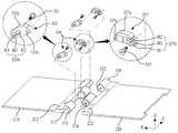
도 1은 본 발명의 일 예에 따른 접이식 디스플레이 장치에 있어서, 펼쳐진 상태와 접힌 상태를 나타내는 도면이다.
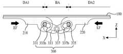
도 2는 도 1에 도시된 접철부를 설명하기 위한 사시도이다.
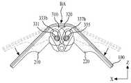
도 3은 도 2에 도시된 접철부를 설명하기 위한 분해 사시도이다.
도 4는 본 발명의 일 예에 따른 접이식 디스플레이 장치의 펼쳐진 상태를 나타내는 도면이다.
도 5a 내지 도 5c는 본 발명의 일 예에 따른 접이식 디스플레이 장치에 있어서, 디스플레이 패널의 벤딩 과정을 설명하기 위한 도면들이다.1 is a diagram illustrating an unfolded state and a folded state in a foldable display device according to an exemplary embodiment of the present invention.
2 is a perspective view for explaining the folded portion shown in FIG. 1.
3 is an exploded perspective view for explaining the folded portion shown in FIG. 2.
4 is a diagram illustrating an unfolded state of a foldable display device according to an exemplary embodiment of the present invention.
5A to 5C are diagrams for explaining a bending process of a display panel in a foldable display device according to an exemplary embodiment of the present invention.
본 명세서에서 서술되는 용어의 의미는 다음과 같이 이해되어야 할 것이다.The meaning of the terms described in this specification should be understood as follows.
단수의 표현은 문맥상 명백하게 다르게 정의하지 않는 한 복수의 표현을 포함하는 것으로 이해되어야 하고, "제 1", "제 2" 등의 용어는 하나의 구성요소를 다른 구성요소로부터 구별하기 위한 것으로, 이들 용어들에 의해 권리범위가 한정되어서는 아니 된다.Singular expressions should be understood as including plural expressions unless clearly defined differently in context, and terms such as “first” and “second” are used to distinguish one element from other elements, The scope of rights should not be limited by these terms.
"포함하다" 또는 "가지다" 등의 용어는 하나 또는 그 이상의 다른 특징이나 숫자, 단계, 동작, 구성요소, 부분품 또는 이들을 조합한 것들의 존재 또는 부가 가능성을 미리 배제하지 않는 것으로 이해되어야 한다.It is to be understood that terms such as "comprises" or "have" do not preclude the presence or addition of one or more other features, numbers, steps, actions, components, parts, or combinations thereof.
"적어도 하나"의 용어는 하나 이상의 관련 항목으로부터 제시 가능한 모든 조합을 포함하는 것으로 이해되어야 한다. 예를 들어, "제 1 항목, 제 2 항목 및 제 3 항목 중에서 적어도 하나"의 의미는 제 1 항목, 제 2 항목 또는 제 3 항목 각각 뿐만 아니라 제 1 항목, 제 2 항목 및 제 3 항목 중에서 2개 이상으로부터 제시될 수 있는 모든 항목의 조합을 의미한다.The term “at least one” is to be understood as including all possible combinations from one or more related items. For example, the meaning of “at least one of the first item, the second item, and the third item” means that each of the first item, the second item, or the third item, as well as the first item, the second item, and the third item, It means a combination of all items that can be presented from more than one.
"상에"라는 용어는 어떤 구성이 다른 구성의 바로 상면에 형성되는 경우 뿐만 아니라 이들 구성들 사이에 제3의 구성이 개재되는 경우까지 포함하는 것을 의미한다.The term "on" is meant to include not only a case where a certain structure is formed directly on the top surface of another structure, but also a case where a third structure is interposed between these elements.
이하에서는 본 발명에 따른 접이식 디스플레이 장치의 바람직한 예를 첨부된 도면을 참조하여 상세히 설명한다.Hereinafter, a preferred example of a foldable display device according to the present invention will be described in detail with reference to the accompanying drawings.
도 1은 본 발명의 일 예에 따른 접이식 디스플레이 장치에 있어서, 펼쳐진 상태와 접힌 상태를 나타내는 도면이고, 도 2는 도 1에 도시된 접철부를 설명하기 위한 사시도이며, 도 3은 도 2에 도시된 접철부를 설명하기 위한 분해 사시도이다.1 is a view showing an unfolded state and a folded state in a foldable display device according to an exemplary embodiment of the present invention, and FIG. 2 is a perspective view illustrating a folded portion illustrated in FIG. 1, and FIG. 3 is It is an exploded perspective view for explaining the folded portion.
도 1 내지 도 3을 참조하면, 본 발명의 일 예에 따른 접이식 디스플레이 장치는 디스플레이 패널(100), 제 1 및 제 2 패널 지지 부재(210, 220), 및 접철부(300)를 포함하여 구성된다.1 to 3, a foldable display device according to an exemplary embodiment of the present invention includes a
상기 디스플레이 패널(100)은 플렉서블 기판을 이용한 플렉서블 디스플레이 패널이 될 수 있다. 일 예로서, 상기 디스플레이 패널(100)은 플렉서블 유기 발광 디스플레이 패널(Flexible Organic Light Emitting Display Panel), 플렉서블 전기 영동 디스플레이 패널(Flexible Electrophoretic Display Panel), 플렉서블 액정 디스플레이 패널(Flexible Liquid Crystal Display Panel), 또는 플렉서블 전자 습윤 디스플레이 패널(Flexible Electro-Wetting Display Panel) 등이 될 수 있다.The
상기 디스플레이 패널(100)은 영상을 표시하기 위한 복수의 화소로 이루어진 화소 어레이를 포함하는 플렉서블 기판, 및 화소 어레이를 보호하는 봉지 부재를 포함한다.The
상기 플렉서블 기판은 플라스틱 재질로 이루어지거나 금속 포일(Foil)로 이루어질 수 있다. 예를 들어, 상기 플라스틱 재질의 플렉서블 기판은 PI(Polyimide), PET(Polyethyleneterephthalate), PEN(Polyethylenapthanate), PC(Polycarbonate), PNB(Polynorborneen), 및 PES(Polyethersulfone) 중 어느 하나의 재질로 이루어질 수 있다.The flexible substrate may be made of a plastic material or a metal foil. For example, the plastic flexible substrate may be made of any one of PI (Polyimide), PET (Polyethyleneterephthalate), PEN (Polyethylenapthanate), PC (Polycarbonate), PNB (Polynorborneen), and PES (Polyethersulfone). .
상기 화소는 영상 신호에 대응되는 영상을 표시하는 표시 소자를 포함하여 이루어진다. 여기서, 표시 소자는 유기 발광 소자, 액정 표시 소자, 전기 영동 소자, 또는 전자 습윤 표시 소자 등이 될 수 있다.The pixel includes a display element that displays an image corresponding to an image signal. Here, the display device may be an organic light emitting device, a liquid crystal display device, an electrophoretic device, or an electrowetting display device.
상기 봉지 부재는 화소 어레이를 덮도록 플렉서블 기판 상에 형성되는 것으로, 플렉서블 봉지 기판 또는 봉지층이 될 수 있다.The encapsulation member is formed on the flexible substrate to cover the pixel array, and may be a flexible encapsulation substrate or an encapsulation layer.
추가적으로, 상기 디스플레이 패널(100)은 봉지 부재에 부착된 편광 필름을 더 포함하여 이루어질 수도 있으나, 상기 편광 필름은 디스플레이 패널(100)의 유연성을 위해 생략 가능하다.Additionally, the
한편, 본 발명의 일 예에 따른 접이식 디스플레이 장치는 사용자의 터치를 이용한 사용자 인터페이스를 위해 터치 스크린(미도시)을 더 포함하여 구성될 수 있으며, 상기 터치 스크린은 디스플레이 패널(100) 상에 부착되거나 상기 화소 어레이의 형성 공정과 함께 디스플레이 패널(100)에 내장될 수 있다.Meanwhile, the foldable display device according to an example of the present invention may further include a touch screen (not shown) for a user interface using a user's touch, and the touch screen may be attached to the
이와 같은, 디스플레이 패널(100)은 복수의 화소로 이루어지는 표시 영역(DA)을 포함하며, 상기 표시 영역(DA)은 패널 구동부(미도시)의 구동에 따라 소정의 영상을 표시하는 표시 화면이 될 수 있다. 이러한 표시 영역(DA)은 제 1 표시 영역(DA1), 제 2 표시 영역(DA2), 및 벤딩 영역(BA)으로 구분될 수 있다.As such, the
상기 디스플레이 패널(100)의 접힘시, 제 1 및 제 2 표시 영역(DA1, DA2)에는 서로 동일하거나 다른 영상이 동시 또는 선택적으로 표시될 수 있는데, 이 경우, 접이식 디스플레이 장치의 전면 및 후면에는 서로 동일하거나 다른 영상이 동시 또는 선택적으로 표시될 수 있다.When the
상기 벤딩 영역(BA)은 디스플레이 패널(100)의 접힘시 디스플레이 패널(100)이 벤딩되어 일정한 곡률을 가지는 디스플레이 패널(100)의 벤딩부를 형성하기 위해, 표시 영역(DA)의 일부 영역, 예를 들어, 상기 제 1 및 제 2 표시 영역(DA1, DA2) 사이의 영역으로 설정될 수 있다. 이러한 상기 벤딩 영역(BA)에는 디스플레이 패널(100)의 접힘시 보조 영상이 표시될 수 있다. 예를 들어, 본 발명의 일 예에 따른 접이식 디스플레이 장치가 휴대용 정보 기기일 경우, 상기 보조 영상은 배터리 잔량, 무선 통신 감도, 시간 정보, 및 메시지 수신 아이콘 등이 될 수 있다. 상기 디스플레이 패널(100)의 펼침시, 상기 벤딩 영역(BA)은 상기 제 1 및 제 2 표시 영역(DA1, DA2) 사이에 평면 형태로 형성됨으로써 상기 제 1 및 제 2 표시 영역(DA1, DA2)과 함께 하나의 넓은 화면을 구성할 수 있다.The bending area BA is a partial area of the display area DA, for example, in order to form a bending portion of the
상기 디스플레이 패널(100)은 일측 가장자리 부분으로부터 일정한 폭과 길이를 가지도록 연장된 신호 인가부(110)를 포함한다. 상기 신호 인가부(110)에는 화소 어레이에 형성된 신호 배선과 연결되는 링크 라인들이 형성되어 있다. 이러한 신호 인가부(110)는 제 2 패널 지지 부재(220)의 외측면을 감싸도록 제 2 패널 지지 부재(200)의 후면 쪽으로 벤딩되어 패널 구동부에 연결됨으로써 패널 구동부로부터 공급되는 화소 구동 신호와 데이터 신호를 화소 어레이에 공급한다.The
상기 제 1 및 제 2 패널 지지 부재(210, 220)는 금속 또는 플라스틱 재질로 이루어진 사각 형태로 형성될 수 있다.The first and second
상기 제 1 패널 지지 부재(210)는 디스플레이 패널(100)의 제 1 영역, 예를 들어, 제 1 표시 영역(DA1)을 포함하는 디스플레이 패널(100)의 제 1 영역을 지지한다. 이때, 상기 제 1 패널 지지 부재(210)의 내측 가장자리 부분에는 일정한 높이로 돌출된 제 1 돌출부(212)가 형성될 수 있으며, 이러한 제 1 돌출부(212)가 형성되지 않는 상기 제 1 패널 지지 부재(210)의 나머지 하면은 제 1 돌출부(212)와 단차짐으로써 상기 접이식 디스플레이 장치의 구동에 필요한 구동 수단들(예를 들어, 통신 회로, 전원 회로, 배터리, 제어 회로, 메모리, 연산 회로 등)이 수납되는 제 1 수납 공간으로 활용될 수 있다.The first
상기 제 2 패널 지지 부재(220)는 디스플레이 패널(100)의 제 2 영역, 예를 들어, 제 2 표시 영역(DA2)을 포함하는 디스플레이 패널(100)의 제 2 영역을 지지한다. 이때, 상기 제 2 패널 지지 부재(220)의 내측 가장자리 부분에는 일정한 높이로 돌출된 제 2 돌출부(222)가 형성될 수 있으며, 이러한 제 2 돌출부(222)가 형성되지 않는 상기 제 2 패널 지지 부재(220)의 나머지 하면은 제 2 돌출부(222)와 단차짐으로써 디스플레이 패널(100)을 구동하기 위한 패널 구동부 등이 수납되는 제 2 수납 공간으로 활용될 수 있다.The second
상기 제 2 패널 지지 부재(220)의 외측 가장자리 부분은 일정한 폭과 길이를 가지도록 형성된 홈부(224)를 포함한다. 상기 홈부(224)는 신호 인가부(110)가 외부로 노출되는 것을 방지한다. 즉, 신호 인가부(110)는 디스플레이 패널(100)으로부터 홈부(224)를 감싸도록 제 2 패널 지지 부재(220)의 후면으로 벤딩됨으로써 제 2 패널 지지 부재(220)의 외측면 외부로 노출되지 않게 된다.The outer edge portion of the second
상기 접철부(300)는 디스플레이 패널(100)의 벤딩 영역(BA)에 중첩되도록 제 1 및 제 2 패널 지지 부재(210, 220) 간에 연결되어 제 1 및 제 2 패널 지지 부재(210, 220) 간의 거리를 조절함으로써 디스플레이 패널(100)이 벤딩 영역(BA)을 기준으로 일정한 곡률로 접히거나 평면 상태로 펼쳐지도록 한다. 즉, 접철부(300)는 상기 디스플레이 패널(100)의 접힘시, 서로 마주보는 제 1 및 제 2 패널 지지 부재(210, 220) 각각의 내측부를 서로 중첩시켜 벤딩 영역(BA)이 일정한 곡률로 벤딩되도록 한다. 그리고, 접철부(300)는 디스플레이 패널(100)의 펼침시, 상기 제 1 및 제 2 패널 지지 부재(210, 220)를 이격시켜 벤딩 영역(BA)이 평면 형태로 펴지도록 한다.The
일 예에 따른 접철부(300)는 하나 이상의 제 1 회전축(310), 하나 이상의 제 2 회전축(320), 및 캠 링크부(330)를 포함하여 구성될 수 있다. 여기서, 상기 제 1 및 제 2 회전축(310, 320) 각각은 하나로 구성될 수도 있지만, 디스플레이 패널(100)의 보다 안정적으로 펼쳐지거나 접힐 수 있도록 복수로 구성되는 것이 바람직하다.The
상기 복수의 제 1 회전축(310)은 제 1 패널 지지 부재(210)의 내측면에 일정한 간격으로 형성된다. 이러한 복수의 제 1 회전축(310) 각각은 일정한 곡률로 형성된 제 1 라운딩부(312)를 포함한다. 제 1 라운딩부(312)는 디스플레이 패널(100)의 접힘시, 벤딩 영역(BA)이 설정된 곡률로 벤딩되도록 벤딩 영역(BA)의 벤딩을 가이드함과 아울러 벤딩된 벤딩 영역(BA)의 곡률이 안정적으로 유지되도록 벤딩된 벤딩 영역(BA)을 지지한다. 즉, 제 1 라운딩부(312)는 동일한 곡률을 가지도록 형성되어 벤딩된 벤딩 영역(BA)을 지지함으로써 벤딩된 벤딩 영역(BA)이 외력에 의해 휘어지거나 눌려지는 것을 방지한다. 이러한 복수의 제 1 회전축(310)은 제 1 패널 지지 부재(210)의 내측면과 나란한 길이를 가지는 원통 형태로 형성될 수 있다.The plurality of
상기 복수의 제 2 회전축(320)은 상기 복수의 제 1 회전축(310)과 엇갈리도록 제 2 패널 지지 부재(220)의 내측면에 일정한 간격으로 형성된다. 즉, 상기 복수의 제 2 회전축(320)은 상기 복수의 제 1 회전축(310) 사이에 삽입 가능하도록 제 2 패널 지지 부재(220)의 내측면에 일정한 간격으로 형성된다. 이러한 상기 복수의 제 2 회전축(320)은 제 1 회전축(310)과 동일한 형태로 형성되는 것으로, 일정한 곡률로 형성된 제 2 라운딩부(322)를 포함함으로써 디스플레이 패널(100)의 접힘시, 벤딩 영역(BA)이 설정된 곡률로 벤딩되도록 벤딩 영역(BA)의 벤딩을 가이드함과 아울러 벤딩된 벤딩 영역(BA)의 곡률이 안정적으로 유지되도록 벤딩된 벤딩 영역(BA)을 지지한다.The plurality of
상기 캠 링크부(330)는 제 1 및 제 2 회전축(310, 320) 간에 연결되고, 제 1 및 제 2 회전축(310, 320)의 회전에 따라 제 1 및 제 2 회전축(310, 320)을 서로 중첩시키거나 이격시킴으로써 디스플레이 패널(100)이 접히거나 펼쳐지도록 한다.The
일 예에 따른 캠 링크부(330)는 제 1 캠(331), 제 1 링크(333), 제 2 캠(335), 및 제 2 링크(337)를 포함하여 구성될 수 있다.The
상기 제 1 캠(331)은 제 1 회전축(310)의 일측면에 결합되어 제 1 회전축(310)과 함께 회전한다. 일 예로서, 제 1 캠(331)은 타원 기둥을 포함하는 캠 볼트로 이루어져, 제 1 회전축(310)의 일측면에 형성된 제 1 체결 홀(미도시)에 체결될 수 있다. 다른 예로서, 제 1 캠(331)은 타원 형태의 단면을 가지도록 제 1 회전축(310)의 일측면으로부터 일정한 높이로 돌출된 타원 기둥일 수 있다. 이러한 제 1 캠(331)의 장축 방향은 제 1 패널 지지 부재(210)의 길이 방향(X)에 수직한 방향(Z)과 나란할 수 있다.The
상기 제 1 링크(333)는 제 1 캠(331)의 회전 및 이동을 가이드하고, 제 1 캠(331)의 이동에 따라 회전되어 디스플레이 패널(100)이 접혀지거나 펼쳐지도록 한다. 일 예에 따른 제 1 링크(333)는 제 1 링크 몸체(333a), 제 1 캠 가이드 홀(333b), 및 샤프트 홀(333c)을 포함하여 구성될 수 있다.The
상기 제 1 링크 몸체(333a)는 일정한 길이를 가지도록 형성되며, 제 1 회전축(310)의 회전을 방해하지 않도록 단차부와 홈부를 포함할 수 있다.The
상기 제 1 캠 가이드 홀(333b)은 제 1 링크 몸체(333a)의 일측부에 두께 방향으로 관통하도록 형성되어 제 1 캠(331)의 회전 및 이동을 가이드 한다. 일 예에 따른 제 1 캠 가이드 홀(333b)은 제 1 링크 몸체(333a)의 일측 영역에 서로 나란하게 형성되어 제 1 캠(331)이 회전 가능하게 삽입되는 제 1 및 제 2 캠 회전 홀(H1, H2), 및 제 1 캠 회전 홀(H1) 또는 제 2 캠 회전 홀(H2)에 위치한 제 1 캠(331)이 회전 각도에 따라 선택적으로 이동되도록 제 1 및 제 2 캠 회전 홀(H1, H2) 간에 연통된 홀 연통부(H3)를 포함하여 구성될 수 있다. 예를 들어, 제 1 및 제 2 캠 회전 홀(H1, H2) 각각은 제 1 캠(331)의 장축 지름보다 큰 지름을 가지도록 서로 나란하게 형성되며, 제 1 및 제 2 캠 회전 홀(H1, H2) 각각의 중심부는 제 1 또는 제 2 캠 회전 홀(H1, H2)의 지름보다 작은 간격으로 이격되고, 이로 인하여 제 1 및 제 2 캠 회전 홀(H1, H2)은 서로 연통되도록 겹쳐지게 된다. 이에 따라, 홀 연통부(H3)는 제 1 및 제 2 캠 회전 홀(H1, H2)이 서로 겹쳐지는 영역으로서, 홀 연통부(H3)의 아랫면과 윗면 사이의 간격은 제 1 캠(331)의 장축 지름보다 작은 제 1 캠(331)의 단축 지름보다 크게 형성된다. 따라서, 제 1 캠(331)은 제 1 또는 제 2 캠 회전 홀(H1, H2) 내에서 회전 가능하게 되고, 제 1 회전축(310)의 회전에 따른 장축 방향의 회전 각도에 따라 선택적으로 홀 연통부(H3)를 통해 제 1 및 제 2 캠 회전 홀(H1, H2) 간에 이동하게 된다.The first
상기 샤프트 홀(333c)은 제 1 링크 몸체(333a)의 일측부와 반대되는 타측부를 두께 방향으로 관통하여 형성될 수 있다. 상기 샤프트 홀(333c)은 제 1 캠(331)의 이동에 따라 회전되는 상기 제 1 링크(333)의 회전 중심축이 될 수 있다.The
한편, 상기 제 1 링크(333)는 샤프트 홀(333c) 대신에 샤프트 홈을 포함할 수 있다. 샤프트 홈은 제 1 링크 몸체(333a)의 길이 방향을 기준으로, 제 1 링크 몸체(333a)의 타측부 측면으로부터 일정한 깊이로 오목하게 형성될 수 있다.Meanwhile, the
상기 제 2 캠(335)은 제 1 회전축(310)의 일측면과 마주하는 제 2 회전축(320)의 일측면에 결합되어 제 2 회전축(320)과 함께 회전한다. 일 예로서, 제 2 캠(335)은 타원 기둥을 포함하는 캠 볼트로 이루어져, 제 2 회전축(320)의 일측면에 형성된 제 2 체결 홀(324)에 체결될 수 있다. 다른 예로서, 제 2 캠(335)은 타원 형태의 단면을 가지도록 제 2 회전축(320)의 일측면으로부터 일정한 높이로 돌출된 타원 기둥일 수 있다. 이러한 제 2 캠(335)의 장축 방향은 제 2 패널 지지 부재(220)의 길이 방향(X)에 수직한 방향(Z)과 나란할 수 있다.The
상기 제 2 링크(337)는 제 2 캠(335)의 회전 및 이동을 가이드하고, 제 2 캠(335)의 이동에 따라 회전되어 디스플레이 패널(100)이 접혀지거나 펼쳐지도록 한다. 일 예에 따른 제 2 링크(333)는 제 2 링크 몸체(337a), 제 2 캠 가이드 홀(337b), 및 샤프트(337c)를 포함하여 구성될 수 있다.The
상기 제 2 링크 몸체(335a)는 일정한 길이를 가지도록 형성되며, 제 2 회전축(320)의 회전을 방해하지 않도록 단차부와 홈부를 포함할 수 있다.The second link body 335a is formed to have a certain length, and may include a stepped portion and a groove portion so as not to interfere with the rotation of the
상기 제 2 캠 가이드 홀(337b)은 제 2 링크 몸체(337a)의 일측부에 두께 방향으로 관통하도록 형성되어 제 2 캠(335)의 회전 및 이동을 가이드 한다. 일 예에 따른 제 2 캠 가이드 홀(337b)은 제 2 링크 몸체(337a)의 일측 영역에 서로 나란하게 형성되어 제 2 캠(335)이 회전 가능하게 삽입되는 제 1 및 제 2 캠 회전 홀(H1, H2), 및 제 1 캠 회전 홀(H1) 또는 제 2 캠 회전 홀(H2)에 위치한 제 2 캠(335)이 회전 각도에 따라 선택적으로 이동되도록 제 1 및 제 2 캠 회전 홀(H1, H2) 간에 연통된 홀 연통부(H3)를 포함하여 구성될 수 있다. 이러한 제 1 및 제 2 캠 회전 홀(H1, H2)과 홀 연통부(H3) 각각은 전술한 바와 동일하므로 이에 대한 중복 설명은 생략하기로 한다. 따라서, 제 2 캠(335)은 제 1 또는 제 2 캠 회전 홀(H1, H2) 내에서 회전 가능하게 되고, 제 2 회전축(320)의 회전에 따른 장축 방향의 회전 각도에 따라 선택적으로 홀 연통부(H3)를 통해 제 1 및 제 2 캠 회전 홀(H1, H2) 간에 이동하게 된다.The second
상기 샤프트(337c)는 상기 제 1 링크(333)에 형성된 샤프트 홀(333c)(또는 샤프트 홈)에 회전 가능하게 삽입되도록 제 2 링크 몸체(337a)의 일측부와 반대되는 타측부 측면으로부터 원 기둥 형태를 가지도록 일정한 높이로 돌출되어 형성된다. 이러한 상기 샤프트(337c)는 제 2 캠(335)의 이동에 따라 회전되는 상기 제 2 링크(335)의 회전 중심축이 될 수 있다. 이에 따라, 제 1 및 제 2 링크(333, 337)는 샤프트(337c)를 회전 중심축으로 하여, 제 1 및 제 2 캠(331, 335) 각각의 이동에 따라 회전된다. 이때, 제 1 및 제 2 링크(333, 337)는 디스플레이 패널(100)의 펼침시 샤프트(337c)를 중심으로 이격된다. 반면에, 제 1 및 제 2 링크(333, 337)는 디스플레이 패널(100)의 접힘시에는 샤프트(337c)를 중심으로 서로 엇갈리게 중첩되어 복수의 제 1 및 제 2 회전축(210, 220)이 서로 엇갈리는 형태로 중첩되도록 한다.The
한편, 상기 제 2 링크(337)에서 샤프트(337c)는 샤프트 핀으로 대체될 수 있으며, 이 경우, 샤프트 핀은 제 2 링크 몸체(337a)의 타측부를 관통하여 상기 제 1 링크(333)에 형성된 샤프트 홀(333c)(또는 샤프트 홈)에 삽입되어 회전 중심축의 역할을 하게 된다.On the other hand, in the
다시 도 1에서, 본 발명의 일 예에 따른 접이식 디스플레이 장치는 제 1 및 제 2 패널 지지 부재(210, 220) 사이에 설치되어 상기 디스플레이 패널(100)을 지지하는 베이스 플레이트(400)를 더 포함하여 구성될 수 있다.In FIG. 1 again, the foldable display device according to an embodiment of the present invention further includes a base plate 400 installed between the first and second
상기 베이스 플레이트(400)는 상기 접철부(300)를 덮도록 제 1 및 제 2 패널 지지 부재(210, 220) 각각의 상면에 결합되어 디스플레이 패널(100)을 지지한다. 이러한 베이스 플레이트(400)는 플렉서블 플라스틱 재질로 이루어지거나, 디스플레이 패널(100)의 방열을 위해 플렉서블 금속 재질로 이루어질 수 있다.The base plate 400 is coupled to an upper surface of each of the first and second
상기 디스플레이 패널(100)은 상기 베이스 플레이트(400) 상에 배치되는데, 상기 디스플레이 패널(100)이 베이스 플레이트(400)의 상면 전체에 부착 고정된 경우, 벤딩 영역(BA)의 벤딩시 길이가 변화될 수 있으며, 이로 인해 펼쳐진 디스플레이 패널(100)의 벤딩 영역(BA)에서 들뜸 현상이 발생될 수 있다. 이에 따라, 상기 디스플레이 패널(100)의 길이 변화에 따른 벤딩 영역(BA)의 들뜸 현상을 방지 내지 최소화하기 위해, 상기 디스플레이 패널(100)의 일측 또는 타측 가장자리 부분만이 베이스 플레이트(400)의 상면에 부착 내지 결합되는 것이 바람직하다. 이와 마찬가지로, 상기 베이스 플레이트(400)의 일측 또는 타측 가장자리 부분만이 제 1 또는 제 2 패널 지지 부재(210, 220)의 상면에 부착 내지 결합되는 것이 바람직하다.The
한편, 본 발명의 일 예에 따른 접이식 디스플레이 장치는 상기 제 1 및 제 2 패널 지지 부재(210, 220) 각각의 외측면을 감싸고, 디스플레이 패널(100)의 전면(前面) 가장자리 부분을 둘러싸는 외장 케이스를 더 포함하여 구성될 수 있다.On the other hand, the foldable display device according to an embodiment of the present invention surrounds the outer surfaces of each of the first and second
상기 외장 케이스는 벤딩 영역(BA)의 양측부를 제외한 상기 제 1 및 제 2 패널 지지 부재(210, 220) 각각의 외측면을 감싸는 제 1 및 제 2 외장 하부 케이스, 벤딩 영역(BA)을 제외한 디스플레이 패널(100)의 전면(前面) 가장자리 부분을 둘러싸는 제 1 및 제 2 외장 전면 케이스, 및 벤딩 영역(BA)의 하부와 양측부를 감싸면서 디스플레이 패널(100)의 접힘 또는 펼침에 따라 벤딩되는 유연한 재질로 이루어진 힌지 케이스를 포함하여 구성될 수 있다. 또한, 제 1 및 제 2 외장 하부 케이스에는 디스플레이 패널(100)을 접힌 상태로 유지시키거나 디스플레이 패널(100)의 접힌 상태를 해제하기 위한 후크 등의 접철 개폐 부재가 형성될 수 있다.The outer case includes first and second outer lower cases surrounding the outer surfaces of each of the first and second
도 4는 본 발명의 일 예에 따른 접이식 디스플레이 장치의 펼쳐진 상태를 나타내는 도면이다.4 is a diagram illustrating an unfolded state of a foldable display device according to an exemplary embodiment of the present invention.
도 4에서 알 수 있듯이, 디스플레이 패널(100)의 펼침시, 디스플레이 패널(100)의 제 1 및 제 2 표시 영역(DA1, DA2)과 벤딩 영역(BA)은 평면 형태로 펼쳐지게 된다. 이때, 제 1 및 제 2 패널 지지 부재(210, 220) 각각은 접철부(300)에 의해 일정한 간격으로 이격됨으로써 벤딩 영역(BA)이 평면 형태로 펴지도록 한다. 이와 같이, 디스플레이 패널(100)이 펼쳐진 상태에서, 제 1 및 제 2 캠(331, 335) 각각의 장축 방향이 패널 지지 부재(210, 220)의 길이 방향(X)과 수직한 방향(Z)과 나란하기 때문에 제 1 및 제 2 캠(331, 335) 각각은 캠 가이드 홀(333b, 337b) 내에서 회전 가능하지만, 캠 가이드 홀(333b, 337b)의 제 1 및 제 2 캠 회전 홀 간에 이동하지 못하게 된다. 따라서, 디스플레이 패널(100)이 펼쳐진 상태에서, 외력(EF)이 패널 지지 부재(210, 220)의 길이 방향(X)으로 가해지더라도 제 1 및 제 2 캠(331, 335) 각각의 이동이 캠 가이드 홀(333b, 337b)의 홀 연통부에 의해 구속됨으로써 디스플레이 패널(100)은 평면 형태로 펼쳐진 상태를 안정적으로 유지하게 된다.As can be seen in FIG. 4, when the
도 5a 내지 도 5c는 본 발명의 일 예에 따른 접이식 디스플레이 장치에 있어서, 디스플레이 패널의 벤딩 과정을 설명하기 위한 도면들로서, 이하의 설명에서는 디스플레이 패널의 벤딩 과정에 대해서만 설명하기로 한다.5A to 5C are diagrams for explaining a bending process of a display panel in a foldable display device according to an exemplary embodiment of the present invention. In the following description, only the bending process of the display panel will be described.
먼저, 도 4에 도시된 바와 같이 디스플레이 패널(100)이 평면 형태로 펼쳐진 상태에서, 도 5a에 도시된 바와 같이, 디스플레이 패널(100)이 접히는 방향으로 제 1 및 제 2 패널 지지 부재(210, 220) 각각이 회전하게 되면, 제 1 및 제 2 캠(331, 335) 각각은 제 1 및 제 2 패널 지지 부재(210, 220) 각각의 회전에 따른 제 1 및 제 2 회전축(310, 320) 각각의 회전과 함께 회전하게 된다. 이에 따라, 제 1 및 제 2 캠(331, 335) 각각이 캠 가이드 홀(333b, 337b)의 제 1 홀 내에서 회전하면서 제 1 및 제 2 캠(331, 335) 각각은 캠 가이드 홀(333b, 337b) 내에서 이동 가능하게 된다. 즉, 제 1 및 제 2 캠(331, 335) 각각이 회전하게 되면, 제 1 및 제 2 캠(331, 335) 각각의 장축 방향의 일측부가 캠 가이드 홀(333b, 337b)의 홀 연통부 내부로 삽입되게 된다. 이와 동시에, 제 1 및 제 2 회전축(310, 320) 각각이 회전함에 따라 디스플레이 패널(100)의 벤딩 영역(BA)은 제 1 및 제 2 회전축(310, 320)의 벤딩 가이드에 따라 벤딩되기 시작한다.First, as shown in FIG. 4, in a state in which the
이어, 도 5b에 도시된 바와 같이, 디스플레이 패널(100)이 접히는 방향으로 제 1 및 제 2 패널 지지 부재(210, 220) 각각이 더 회전하게 되면, 제 1 및 제 2 회전축(310, 320) 각각의 회전에 따라 제 1 및 제 2 캠(331, 335) 각각이 회전하면서 캠 가이드 홀(333b, 337b)의 홀 연통부를 통해 제 1 홀에서 제 2 홀 쪽으로 이동하게 된다. 이와 동시에, 제 1 및 제 2 회전축(310, 320) 각각이 회전함에 따라 디스플레이 패널(100)의 벤딩 영역(BA)은 제 1 및 제 2 회전축(310, 320)의 벤딩 가이드에 따라 추가적으로 벤딩되게 된다.Subsequently, as shown in FIG. 5B, when each of the first and second
이어, 도 5c에 도시된 바와 같이, 디스플레이 패널(100)이 접히는 방향으로 제 1 및 제 2 패널 지지 부재(210, 220) 각각이 더 회전하여 제 1 및 제 2 패널 지지 부재(210, 220) 각각이 서로 겹쳐지게 되면, 제 1 및 제 2 회전축(310, 320) 각각이 회전되어 서로 겹쳐짐에 따라 제 1 및 제 2 링크(333, 337) 역시 서로 겹쳐지게 된다. 이에 따라, 제 1 및 제 2 회전축(310, 320) 각각이 회전되어 서로 겹쳐짐에 따라 디스플레이 패널(100)의 벤딩 영역(BA)은 제 1 및 제 2 회전축(310, 320)에 형성된 라운딩부의 곡률에 대응되는 곡률을 가지도록 벤딩되게 된다. 이와 동시에, 제 1 및 제 2 캠(331, 335) 각각은 캠 가이드 홀(333b, 337b)의 제 2 홀 내에서 회전함으로써 제 1 및 제 2 캠(331, 335) 각각의 장축 방향이 패널 지지 부재(210, 220)의 길이 방향(X)과 수직한 방향(Z)과 나란하게 된다. 이에 따라, 제 1 및 제 2 캠(331, 335) 각각은 캠 가이드 홀(333b, 337b)의 제 2 홀 내에서 회전 가능하지만, 캠 가이드 홀(333b, 337b) 내에서 이동하지 못하게 된다. 이에 따라, 디스플레이 패널(100)이 벤딩 영역(BA)을 기준으로 접혀진 상태에서, 벤딩 영역(BA)에 외력(EF)이 가해지더라도 제 1 및 제 2 캠(331, 335) 각각의 이동이 캠 가이드 홀(333b, 337b)의 홀 연통부에 의해 구속됨으로써 벤딩된 디스플레이 패널(100)의 벤딩 영역(BA)은 제 1 및 제 2 회전축(310, 320)의 라운딩부에 지지되므로 일정한 곡률로 벤딩된 상태를 안정적으로 유지하게 된다.Subsequently, as shown in FIG. 5C, each of the first and second
이상에서 설명한 본 발명은 전술한 실시 예 및 첨부된 도면에 한정되는 것이 아니고, 본 발명의 기술적 사항을 벗어나지 않는 범위 내에서 여러 가지 치환, 변형 및 변경이 가능하다는 것이 본 발명이 속하는 기술 분야에서 통상의 지식을 가진 자에게 있어 명백할 것이다. 그러므로, 본 발명의 범위는 후술하는 특허청구범위에 의하여 나타내어지며, 특허청구범위의 의미 및 범위 그리고 그 등가 개념으로부터 도출되는 모든 변경 또는 변형된 형태가 본 발명의 범위에 포함되는 것으로 해석되어야 한다.The present invention described above is not limited to the above-described embodiments and the accompanying drawings, and it is common in the technical field to which the present invention pertains that various substitutions, modifications and changes are possible within the scope of the technical matters of the present invention. It will be obvious to those who have the knowledge of. Therefore, the scope of the present invention is indicated by the claims to be described later, and all changes or modified forms derived from the meaning and scope of the claims and their equivalent concepts should be interpreted as being included in the scope of the present invention.
100: 디스플레이 패널 210: 제 1 패널 지지 부재
220: 제 2 패널 지지 부재 300: 접철부
310: 제 1 회전축 312: 제 1 라운딩부
320: 제 2 회전축 322: 제 2 라운딩부
330: 캠 링크부 331: 제 1 캠
333: 제 1 링크 335: 제 2 캠
337: 제 2 링크 400: 베이스 플레이트100: display panel 210: first panel support member
220: second panel support member 300: folded portion
310: first rotation shaft 312: first rounding portion
320: second rotation shaft 322: second rounding portion
330: cam link unit 331: first cam
333: first link 335: second cam
337: second link 400: base plate
Claims (10)
Translated fromKorean상기 제 1 표시 영역에 대응되는 디스플레이 패널의 제 1 영역을 지지하는 제 1 패널 지지 부재;
상기 제 2 표시 영역에 대응되는 상기 디스플레이 패널의 제 2 영역을 지지하는 제 2 패널 지지 부재; 및
상기 벤딩 영역에 중첩되도록 상기 제 1 및 제 2 패널 지지 부재 간에 연결되어 상기 디스플레이 패널이 상기 벤딩 영역을 기준으로 접히거나 평면 형태로 펼쳐지도록 가이드 하는 접철부를 포함하며,
상기 접철부는,
상기 제 1 패널 지지 부재의 내측면에 형성된 제 1 회전축;
상기 제 1 회전축과 엇갈리도록 상기 제 2 패널 지지 부재의 내측면에 형성된 제 2 회전축; 및
상기 제 1 및 제 2 회전축 간에 연결되고, 상기 제 1 및 제 2 회전축의 회전에 따라 상기 제 1 및 제 2 회전축을 서로 중첩시키거나 이격시키는 캠 링크부를 포함하고,
상기 접철부는 상기 디스플레이 패널이 접히거나 펼쳐질 수 있도록 상기 제 1 및 제 2 패널 지지 부재 간의 거리를 조절하고,
상기 접철부는 상기 디스플레이 패널의 접힘 시, 상기 벤딩 영역이 일정한 곡률로 벤딩되도록 서로 마주보는 상기 제 1 및 제 2 패널 지지 부재의 내측부를 서로 중첩시키며,
상기 제 1 회전축과 상기 제 2 회전축은 상기 디스플레이 패널의 접힘 시 상기 제 1 및 제 2 패널 지지 부재의 길이 방향, 및 상기 제 1 및 제 2 패널 지지 부재의 길이 방향과 수직한 방향 각각에 대해 수직한 상기 제 1 및 제 2 패널지지부재의 폭 방향으로 중첩되는 접이식 디스플레이 장치.A display panel including a first display area, a second display area, and a display area having a bending area defined between the first and second display areas;
A first panel support member supporting a first area of the display panel corresponding to the first display area;
A second panel support member supporting a second area of the display panel corresponding to the second display area; And
A foldable portion connected between the first and second panel support members so as to overlap the bending area to guide the display panel to be folded or unfolded in a flat shape based on the bending area,
The folding part,
A first rotation shaft formed on an inner surface of the first panel support member;
A second rotation shaft formed on an inner surface of the second panel support member so as to be staggered with the first rotation shaft; And
A cam link part connected between the first and second rotation shafts and overlapping or spaced apart the first and second rotation shafts from each other according to rotation of the first and second rotation shafts,
The foldable part adjusts a distance between the first and second panel support members so that the display panel can be folded or unfolded,
The foldable portion overlaps inner portions of the first and second panel support members facing each other so that when the display panel is folded, the bending area is bent at a constant curvature,
When the display panel is folded, the first and second rotational axes are perpendicular to the longitudinal directions of the first and second panel support members, and to a direction perpendicular to the longitudinal directions of the first and second panel support members. A foldable display device overlapping the first and second panel support members in a width direction.
상기 접철부는 상기 디스플레이 패널의 펼침시, 상기 벤딩 영역이 평면 형태로 펴지도록 상기 제 1 및 제 2 패널 지지 부재의 내측부를 이격시키는 접이식 디스플레이 장치.The method of claim 1,
The foldable display device separates the inner portions of the first and second panel support members so that the bent region is unfolded in a flat shape when the display panel is unfolded.
상기 제 1 및 제 2 회전축 각각은 일정한 곡률로 형성된 라운딩부를 포함하고,
상기 제 1 및 제 2 회전축 각각의 라운딩부는 상기 디스플레이 패널의 접힘시, 상기 벤딩 영역의 벤딩을 가이드하고 일정한 곡률로 벤딩된 벤딩 영역을 지지하는 접이식 디스플레이 장치.The method of claim 1,
Each of the first and second rotation shafts includes a rounding portion formed with a constant curvature,
When the display panel is folded, the rounding portions of each of the first and second rotation shafts guide bending of the bending area and support the bending area bent at a constant curvature.
상기 캠 링크부는,
상기 제 1 회전축의 일측면에 설치된 제 1 캠;
상기 제 1 캠을 회전 및 이동 가능하게 지지하는 제 1 링크;
상기 제 1 회전축의 일측면과 나란한 상기 제 2 회전축의 일측면에 설치된 제 2 캠; 및
상기 제 2 캠을 회전 및 이동 가능하게 지지하고, 상기 제 1 링크와 접철 가능하게 결합된 제 2 링크를 포함하여 구성된 접이식 디스플레이 장치.The method of claim 1,
The cam link unit,
A first cam installed on one side of the first rotation shaft;
A first link rotatably and movably supporting the first cam;
A second cam installed on one side of the second rotation shaft parallel to one side of the first rotation shaft; And
A foldable display device configured to include a second link that supports the second cam to be rotatable and movable, and is foldably coupled to the first link.
상기 제 1 및 제 2 링크는 상기 제 1 및 제 2 캠의 회전과 이동에 따라 접철되는 접이식 디스플레이 장치.The method of claim 5,
The first and second links are folded according to the rotation and movement of the first and second cams.
상기 제 1 및 제 2 링크 각각은 해당 캠이 회전 및 이동 가능하게 삽입되는 캠 가이드 홀을 포함하며,
상기 제 1 및 제 2 캠 각각은 회전 각도에 따라 해당 캠 가이드 홀 내에서 선택적으로 이동되는 접이식 디스플레이 장치.The method of claim 6,
Each of the first and second links includes a cam guide hole into which a corresponding cam is rotatably and movably inserted,
Each of the first and second cams is a foldable display device that is selectively moved within a corresponding cam guide hole according to a rotation angle.
상기 제 1 및 제 2 캠 각각은 타원 형태의 단면을 갖는 접이식 디스플레이 장치.The method of claim 7,
Each of the first and second cams has an elliptical cross-section.
상기 캠 가이드 홀은,
서로 나란하게 형성되어 캠이 회전 가능하게 삽입되는 제 1 및 제 2 캠 회전 홀; 및
상기 제 1 및 제 2 캠 회전 홀 간에 연통된 홀 연통부를 포함하며,
상기 캠은 회전 각도에 따라 상기 홀 연통부를 통해 상기 제 1 및 제 2 캠 회전 홀 간에 선택적으로 이동되는 접이식 디스플레이 장치.The method of claim 8,
The cam guide hole,
First and second cam rotation holes formed parallel to each other and into which the cams are rotatably inserted; And
And a hole communication part communicated between the first and second cam rotation holes,
The foldable display device selectively moves the cam between the first and second cam rotation holes through the hole communication part according to a rotation angle.
상기 디스플레이 패널이 접혀지거나 펼쳐진 상태에서, 상기 제 1 및 제 2 캠 각각은 서로 나란하게 형성되어 캠이 회전 가능하게 삽입되는 제 1 및 제 2 캠 회전 홀 간에 이동되지 못하며,
상기 디스플레이 패널이 접혀지거나 펼쳐질 때, 상기 제 1 및 제 2 캠 각각은 상기 제1 및 제2 캠 회전 홀 간에 연통된 홀 연통부를 통해 상기 제 1 및 제 2 캠 회전 홀 간에 이동되는 접이식 디스플레이 장치.The method of claim 8,
When the display panel is folded or unfolded, each of the first and second cams is formed parallel to each other so that the cams cannot be moved between the first and second cam rotation holes into which the cams are rotatably inserted,
When the display panel is folded or unfolded, each of the first and second cams is moved between the first and second cam rotation holes through a hole communication part communicated between the first and second cam rotation holes.
Priority Applications (3)
| Application Number | Priority Date | Filing Date | Title |
|---|---|---|---|
| KR1020140027403AKR102244807B1 (en) | 2014-03-07 | 2014-03-07 | Foldable display apparatus |
| CN201410815310.9ACN104900153B (en) | 2014-03-07 | 2014-12-23 | foldable display device |
| US14/584,605US9603271B2 (en) | 2014-03-07 | 2014-12-29 | Foldable display apparatus |
Applications Claiming Priority (1)
| Application Number | Priority Date | Filing Date | Title |
|---|---|---|---|
| KR1020140027403AKR102244807B1 (en) | 2014-03-07 | 2014-03-07 | Foldable display apparatus |
Publications (2)
| Publication Number | Publication Date |
|---|---|
| KR20150105138A KR20150105138A (en) | 2015-09-16 |
| KR102244807B1true KR102244807B1 (en) | 2021-04-26 |
Family
ID=54018876
Family Applications (1)
| Application Number | Title | Priority Date | Filing Date |
|---|---|---|---|
| KR1020140027403AActiveKR102244807B1 (en) | 2014-03-07 | 2014-03-07 | Foldable display apparatus |
Country Status (3)
| Country | Link |
|---|---|
| US (1) | US9603271B2 (en) |
| KR (1) | KR102244807B1 (en) |
| CN (1) | CN104900153B (en) |
Cited By (1)
| Publication number | Priority date | Publication date | Assignee | Title |
|---|---|---|---|---|
| US12279387B2 (en) | 2021-09-07 | 2025-04-15 | Samsung Electronics Co., Ltd. | Hinge assembly and electronic device including the same |
Families Citing this family (121)
| Publication number | Priority date | Publication date | Assignee | Title |
|---|---|---|---|---|
| US9910458B2 (en)* | 2014-04-24 | 2018-03-06 | Sharp Kabushiki Kaisha | Flexible display device with stoppable hinge |
| TWI525421B (en)* | 2014-07-17 | 2016-03-11 | 緯創資通股份有限公司 | Foldable electronic device and limit structure thereof |
| KR101794872B1 (en)* | 2014-09-28 | 2017-11-09 | 주식회사 가난한동지들 | Flexible display apparatus with ability of over unfolding more than complete plane forming angle |
| CN104506688B (en)* | 2015-01-19 | 2017-05-10 | 京东方科技集团股份有限公司 | Folding mobile terminal |
| CN104836865B (en)* | 2015-04-01 | 2017-05-17 | 京东方科技集团股份有限公司 | Foldable display device |
| KR102369943B1 (en)* | 2015-06-25 | 2022-03-03 | 삼성디스플레이 주식회사 | Foldable display |
| DE102015011403A1 (en)* | 2015-08-29 | 2017-03-16 | Audi Ag | Bendable display for displaying depth information |
| US10331177B2 (en) | 2015-09-25 | 2019-06-25 | Intel Corporation | Hinge for an electronic device |
| US9942367B2 (en)* | 2015-10-13 | 2018-04-10 | Samsung Electronics Co., Ltd. | Electronic device and method for controlling the electronic device thereof |
| FR3042942B1 (en)* | 2015-10-21 | 2017-12-01 | Valeo Vision | FLEXIBLE PRINTED CIRCUIT BOARD AND LUMINOUS MODULE FOR A MOTOR VEHICLE HAVING SUCH A CIRCUIT BOARD |
| US10168733B2 (en)* | 2015-10-23 | 2019-01-01 | Industrial Technology Research Institute | Foldable body and foldable display apparatus |
| KR102421579B1 (en) | 2015-11-16 | 2022-07-18 | 삼성디스플레이 주식회사 | Foldable display apparatus |
| KR102409703B1 (en)* | 2015-12-01 | 2022-06-16 | 엘지디스플레이 주식회사 | Curved display device |
| CN106917814B (en)* | 2015-12-24 | 2024-06-18 | 联想(北京)有限公司 | Rotating shaft and electronic equipment |
| CN105407194A (en)* | 2015-12-29 | 2016-03-16 | 广东欧珀移动通信有限公司 | Mobile terminal with flexible screen |
| CN105549690B (en)* | 2015-12-29 | 2018-01-19 | 广东欧珀移动通信有限公司 | Folding mobile terminal |
| CN105516411B (en)* | 2015-12-29 | 2018-07-06 | 广东欧珀移动通信有限公司 | Folding mobile terminal |
| CN105491193B (en)* | 2015-12-29 | 2018-03-27 | 广东欧珀移动通信有限公司 | Foldable terminal with flexible screen |
| KR20170086801A (en)* | 2016-01-19 | 2017-07-27 | 삼성전자주식회사 | Electronic apparatus and operating method thereof |
| CN105702164B (en)* | 2016-03-30 | 2018-06-22 | 武汉华星光电技术有限公司 | foldable display device |
| KR102401285B1 (en)* | 2016-04-01 | 2022-05-24 | 삼성전자주식회사 | Electronic device comprising display |
| CN105788478A (en)* | 2016-04-07 | 2016-07-20 | 深圳市华星光电技术有限公司 | Display |
| WO2017184816A1 (en)* | 2016-04-22 | 2017-10-26 | E Ink Corporation | Foldable electro-optic display apparatus |
| KR102511590B1 (en)* | 2016-05-02 | 2023-03-20 | 삼성디스플레이 주식회사 | Display device |
| KR102552528B1 (en)* | 2016-05-11 | 2023-07-06 | 삼성디스플레이 주식회사 | Display device |
| USD822658S1 (en) | 2016-06-30 | 2018-07-10 | Intel Corporation | Computer notebook |
| KR102520575B1 (en)* | 2016-07-13 | 2023-04-11 | 삼성디스플레이 주식회사 | Display device |
| CA3034146A1 (en)* | 2016-07-19 | 2018-01-25 | Shenzhen Royole Technologies Co., Ltd. | Flexible device |
| KR102487504B1 (en)* | 2016-08-30 | 2023-01-12 | 삼성디스플레이 주식회사 | Electronic device and operating method of the same |
| KR102636648B1 (en)* | 2016-09-13 | 2024-02-15 | 삼성전자주식회사 | Flexible Display Electronic device |
| KR20180030422A (en)* | 2016-09-15 | 2018-03-23 | 노완동 | 2 Step folderabl Display Device |
| KR102595230B1 (en)* | 2016-10-13 | 2023-10-30 | 삼성전자주식회사 | Foldable electronic device including flexible display |
| CN106448466B (en)* | 2016-10-21 | 2017-12-01 | 京东方科技集团股份有限公司 | foldable display device |
| CN206112430U (en) | 2016-11-01 | 2017-04-19 | 京东方科技集团股份有限公司 | Foldable flexible screen's strutting arrangement and display device |
| CN108076171B (en)* | 2016-11-17 | 2020-04-03 | 华为技术有限公司 | Folding components and mobile terminals |
| JP2018081258A (en)* | 2016-11-18 | 2018-05-24 | 株式会社ジャパンディスプレイ | Display panel and display device |
| CN206559732U (en)* | 2017-01-24 | 2017-10-13 | 深圳视爵光旭电子有限公司 | A kind of device and LED modules for bent plate |
| US10274996B2 (en)* | 2017-01-26 | 2019-04-30 | Guangdong Oppo Mobile Telecommunications Corp., Ltd. | Coupling member, housing assembly and electronic device |
| US10452097B2 (en)* | 2017-01-26 | 2019-10-22 | Guangdong Oppo Mobile Telecommunications Corp., Ltd. | Electronic device |
| CN106603773B (en)* | 2017-01-26 | 2023-04-11 | Oppo广东移动通信有限公司 | Display device and mobile terminal |
| US10268244B2 (en)* | 2017-01-26 | 2019-04-23 | Guangdong Oppo Mobile Telecommunications Corp., Ltd | Housing assembly and electronic device |
| CN106790829B (en)* | 2017-01-26 | 2023-08-04 | Oppo广东移动通信有限公司 | Housing assembly, display device and mobile terminal |
| US10268245B2 (en)* | 2017-01-26 | 2019-04-23 | Guangdong Oppo Mobile Telecommunications Corp., Ltd. | Housing assembly and electronic device |
| WO2018144025A1 (en)* | 2017-02-06 | 2018-08-09 | Hewlett-Packard Development Company, L.P. | Axis shifting hinge assemblies |
| KR102688971B1 (en) | 2017-02-22 | 2024-07-25 | 삼성디스플레이 주식회사 | Foldable display device |
| USD859400S1 (en)* | 2017-03-06 | 2019-09-10 | Progress Technologies, Inc. | Electronic book reader |
| CN107044478B (en)* | 2017-03-15 | 2019-07-26 | 联想(北京)有限公司 | A kind of shaft |
| KR102379216B1 (en)* | 2017-04-24 | 2022-03-28 | 삼성디스플레이 주식회사 | Display apparatus |
| TWI612207B (en)* | 2017-04-25 | 2018-01-21 | 華碩電腦股份有限公司 | Hinge assembly and electronic device using the same |
| USD901495S1 (en) | 2017-05-31 | 2020-11-10 | Samsung Display Co., Ltd. | Display device |
| US10015897B1 (en) | 2017-06-21 | 2018-07-03 | Dell Products L.P. | Flexible information handling system display sliding frame |
| US10120421B1 (en) | 2017-06-21 | 2018-11-06 | Dell Products L.P. | Flexible information handling system display |
| US9964995B1 (en) | 2017-06-21 | 2018-05-08 | Dell Products L.P. | Dynamic antenna orientation with a flexible information handling system display |
| US10082839B1 (en)* | 2017-06-21 | 2018-09-25 | Dell Products L.P. | Flexible information handling system display hinge and ramp support structure |
| US10082838B1 (en) | 2017-06-21 | 2018-09-25 | Dell Products L.P. | Flexible information handling system display external hinge structure |
| CN107358874B (en)* | 2017-06-30 | 2020-02-11 | 武汉天马微电子有限公司 | Flexible display device |
| USD864953S1 (en)* | 2017-07-04 | 2019-10-29 | Samsung Display Co., Ltd. | Display device |
| CN109215507B (en) | 2017-07-07 | 2021-08-27 | 元太科技工业股份有限公司 | Foldable display device |
| KR102340729B1 (en) | 2017-07-31 | 2021-12-16 | 엘지디스플레이 주식회사 | Organic light emitting display device |
| CN107370848B (en)* | 2017-08-25 | 2024-02-20 | Oppo广东移动通信有限公司 | Foldable mobile terminal and its folding mechanism and folding components |
| CN107765773B (en)* | 2017-10-19 | 2020-06-09 | Oppo广东移动通信有限公司 | Method, device, terminal and storage medium for displaying information |
| CN109936648B (en) | 2017-12-18 | 2020-08-07 | 华为技术有限公司 | Slewing mechanism and folding terminal |
| KR102529148B1 (en)* | 2017-12-27 | 2023-05-04 | 엘지디스플레이 주식회사 | Foldable Display Device |
| US10426051B2 (en) | 2017-12-27 | 2019-09-24 | Intel Corporation | Folding devices |
| KR102529149B1 (en)* | 2017-12-27 | 2023-05-04 | 엘지디스플레이 주식회사 | Foldable Display Device |
| KR102567096B1 (en) | 2018-04-03 | 2023-08-17 | 삼성디스플레이 주식회사 | Display device and manufacturing method thereof |
| CN110406235B (en)* | 2018-04-26 | 2021-07-27 | Oppo广东移动通信有限公司 | Manufacturing method of curved screen, curved screen and electronic equipment |
| CN110473468B (en)* | 2018-05-09 | 2022-02-08 | 仁宝电脑工业股份有限公司 | Bending module and folding display device |
| US10234899B1 (en)* | 2018-05-14 | 2019-03-19 | Dell Products, Lp | Information handling system with thin flex hinge |
| CN112470096A (en)* | 2018-07-03 | 2021-03-09 | 深圳市柔宇科技股份有限公司 | Flexible display screen supporting mechanism and flexible display device |
| KR102233336B1 (en)* | 2018-08-14 | 2021-03-29 | 에이피시스템 주식회사 | Bending apparatus and bending method |
| CN108990330B (en)* | 2018-08-29 | 2020-05-12 | Oppo广东移动通信有限公司 | Shell assembly and electronic equipment |
| KR102533161B1 (en)* | 2018-09-18 | 2023-05-18 | 삼성디스플레이 주식회사 | Display device |
| KR102650633B1 (en)* | 2018-11-19 | 2024-03-25 | 엘지디스플레이 주식회사 | Display device |
| CN109300403B (en)* | 2018-11-30 | 2021-07-09 | 上海天马有机发光显示技术有限公司 | A foldable display device |
| CN109545087A (en)* | 2018-12-03 | 2019-03-29 | 武汉华星光电半导体显示技术有限公司 | Foldable back panel structure and its display device |
| KR102624839B1 (en)* | 2018-12-28 | 2024-01-17 | 삼성디스플레이 주식회사 | Display device |
| US10928863B2 (en) | 2019-01-14 | 2021-02-23 | Dell Products L.P. | Portable information handling system midframe to sliding frame assembly |
| US10817030B2 (en) | 2019-01-14 | 2020-10-27 | Dell Products L.P. | Portable information handling system flexible display with alternating slide support frame |
| US10754395B2 (en) | 2019-01-17 | 2020-08-25 | Dell Products L.P. | Multi-axis hinge translation to adjust housing position relative to flexible display position |
| CN109862154B (en)* | 2019-01-25 | 2020-10-16 | 武汉华星光电半导体显示技术有限公司 | Electronic device |
| KR20190020303A (en)* | 2019-02-10 | 2019-02-28 | 심성구 | Foldable Devices for Display |
| CN111536139B (en) | 2019-03-04 | 2021-10-12 | 维沃移动通信有限公司 | chain link |
| CN111696432B (en)* | 2019-03-11 | 2022-05-27 | 深圳市长盈精密技术股份有限公司 | Rotating mechanism, folding mechanism and folding display device |
| KR102864329B1 (en)* | 2019-03-19 | 2025-09-25 | 엘지전자 주식회사 | mobile terminal |
| CN109992054B (en)* | 2019-03-30 | 2021-04-13 | 联想(北京)有限公司 | Electronic equipment and connecting device |
| WO2020209424A1 (en)* | 2019-04-11 | 2020-10-15 | 엘지전자 주식회사 | Flexible display device |
| TWM587285U (en)* | 2019-04-12 | 2019-12-01 | 宏碁股份有限公司 | Electronic device |
| KR102733499B1 (en)* | 2019-04-29 | 2024-11-26 | 삼성디스플레이 주식회사 | Display device |
| KR102709937B1 (en)* | 2019-05-23 | 2024-09-26 | 삼성디스플레이 주식회사 | Foldable display device |
| US12213267B2 (en)* | 2019-05-28 | 2025-01-28 | Apple Inc. | Electronic devices having folding expandable displays |
| PH12021552722A1 (en) | 2019-05-31 | 2022-07-11 | Samsung Electronics Co Ltd | Foldable electronic device including display protection structure |
| CN112081814B (en)* | 2019-06-12 | 2021-06-15 | 仁宝电脑工业股份有限公司 | Double-rotating-shaft module and folding electronic device |
| KR102804985B1 (en)* | 2019-08-19 | 2025-05-12 | 삼성디스플레이 주식회사 | Display apparatus |
| KR102859413B1 (en)* | 2019-08-27 | 2025-09-15 | 삼성디스플레이 주식회사 | Foldable display device and method of operating the same |
| CN114483764B (en) | 2019-08-30 | 2022-11-29 | Oppo广东移动通信有限公司 | Electronic equipment and folding assembly |
| WO2021045272A1 (en)* | 2019-09-05 | 2021-03-11 | 엘지전자 주식회사 | Mobile terminal and auxiliary device coupled thereto |
| KR20210048022A (en)* | 2019-10-22 | 2021-05-03 | 삼성디스플레이 주식회사 | Foldable display device and hinge device for the same |
| CN114945966A (en)* | 2020-01-10 | 2022-08-26 | 株式会社半导体能源研究所 | Angle adjusting device, supporting tool and display device |
| CN212850572U (en)* | 2020-03-30 | 2021-03-30 | 华为技术有限公司 | a mobile terminal |
| CN111462635B (en)* | 2020-05-22 | 2025-03-18 | 京东方科技集团股份有限公司 | Rollable display device |
| CN111508375B (en)* | 2020-05-28 | 2024-10-11 | 武汉华星光电半导体显示技术有限公司 | Foldable display device |
| KR102825916B1 (en)* | 2020-07-08 | 2025-06-30 | 삼성디스플레이 주식회사 | Electronic device |
| CN111901461B (en)* | 2020-08-21 | 2022-02-25 | 维沃移动通信有限公司 | Electronic device |
| CN112485959B (en)* | 2020-12-01 | 2023-02-17 | 北京字节跳动网络技术有限公司 | Foldable curtain |
| CN214063552U (en)* | 2020-12-15 | 2021-08-27 | 合肥维信诺科技有限公司 | A bending unit, hinge and flexible module bending device |
| CN112652248B (en)* | 2021-01-06 | 2022-07-12 | 武汉华星光电半导体显示技术有限公司 | Folding display panel and folding display device |
| CN112769983B (en)* | 2021-01-21 | 2023-04-25 | 维沃移动通信有限公司 | Electronic equipment |
| CN115132070B (en)* | 2021-03-29 | 2025-03-25 | 北京小米移动软件有限公司 | A folding screen device |
| CN113129753B (en)* | 2021-04-15 | 2023-04-07 | 维沃移动通信有限公司 | Inward folding type electronic equipment |
| EP4101635A1 (en) | 2021-06-11 | 2022-12-14 | Whitestone Co., Ltd. | Display protector |
| CN113421492B (en)* | 2021-06-18 | 2023-10-31 | 武汉华星光电半导体显示技术有限公司 | display device |
| CN113446305B (en)* | 2021-06-25 | 2024-06-04 | 东莞市劲丰电子有限公司 | Transverse and longitudinal bending integrated rotating mechanism |
| KR20230015786A (en)* | 2021-07-23 | 2023-01-31 | 엘지디스플레이 주식회사 | Foldable display device |
| CN113487974B (en)* | 2021-07-30 | 2022-07-12 | 武汉华星光电技术有限公司 | Folding display device |
| CN113724598B (en)* | 2021-08-31 | 2023-07-25 | 京东方科技集团股份有限公司 | Intelligent wearing equipment |
| CN114743462B (en)* | 2022-04-27 | 2023-12-29 | 京东方科技集团股份有限公司 | Display device |
| KR102636256B1 (en)* | 2022-06-15 | 2024-02-14 | 노완동 | Water drop shaped hinge structure |
| KR102619821B1 (en)* | 2022-06-30 | 2024-01-03 | 노완동 | Water drop shaped hinge structure |
| US20240385658A1 (en)* | 2022-07-19 | 2024-11-21 | Chengdu Boe Optoelectronics Technology Co., Ltd. | Support module, display module and display device |
| CN115985198B (en)* | 2023-01-31 | 2025-04-08 | 武汉天马微电子有限公司 | Folding mechanism and display device |
Family Cites Families (31)
| Publication number | Priority date | Publication date | Assignee | Title |
|---|---|---|---|---|
| DE19782261C2 (en)* | 1997-12-24 | 2002-12-12 | Mitsubishi Electric Corp | Attachment construction for a flexible liquid crystal display panel |
| FI118621B (en)* | 2000-08-03 | 2008-01-15 | Nokia Corp | Portable, an open and closed use mode comprising, foldable electronic device and its handle arrangement |
| FI118073B (en)* | 2000-08-03 | 2007-06-15 | Nokia Corp | Portable, at least two modes of use including foldable electronic device and hinged mechanism therefor |
| US6577496B1 (en)* | 2001-01-18 | 2003-06-10 | Palm, Inc. | Non-rigid mounting of a foldable display |
| KR100614898B1 (en)* | 2004-06-01 | 2006-08-25 | 김시환 | Portable display |
| EP1603309B1 (en) | 2004-06-04 | 2008-08-20 | Sony Ericsson Mobile Communications AB | A foldable electronic equipment comprising a slildable hinge including leaf springs |
| KR101221428B1 (en)* | 2004-07-20 | 2013-01-11 | 김시환 | Portable Display Device |
| TWI370419B (en) | 2006-10-31 | 2012-08-11 | Creator Technology Bv | Flexible display supported by hinged frame |
| US7830333B2 (en)* | 2006-12-13 | 2010-11-09 | Palo Alto Research Center Incorporated | Slide-out information display |
| JP2010526335A (en)* | 2007-04-25 | 2010-07-29 | ポリマー、ビジョン、リミテッド | Electronic device with flexible display with edge protector |
| KR20100092222A (en)* | 2009-02-12 | 2010-08-20 | 삼성전자주식회사 | Multi-foldable mobile display apparatus |
| KR101636077B1 (en)* | 2009-09-14 | 2016-07-05 | 삼성전자주식회사 | Portable terminal |
| KR20110029089A (en)* | 2009-09-14 | 2011-03-22 | 유상규 | Display area variable display device |
| US20110128216A1 (en)* | 2009-11-30 | 2011-06-02 | Nokia Corporation | Method and apparatus for a user interface |
| KR101148397B1 (en) | 2010-08-17 | 2012-05-23 | 주식회사 팬택 | Mobile Device |
| KR101672345B1 (en)* | 2010-12-08 | 2016-11-04 | 삼성전자주식회사 | Foldable display apparatus |
| KR101911047B1 (en)* | 2012-07-25 | 2018-10-24 | 삼성디스플레이 주식회사 | Case and display device |
| US8804349B2 (en)* | 2012-10-19 | 2014-08-12 | Samsung Display Co., Ltd. | Foldable display device |
| US8971032B2 (en)* | 2012-11-02 | 2015-03-03 | Blackberry Limited | Support for a flexible display |
| US9013864B2 (en)* | 2012-11-02 | 2015-04-21 | Blackberry Limited | Support for a flexible display |
| US9294597B2 (en)* | 2013-01-25 | 2016-03-22 | Futurewei Technologies, Inc. | Apparatuses and methods for a flexible display on a mobile device |
| KR102020659B1 (en)* | 2013-06-03 | 2019-09-11 | 삼성디스플레이 주식회사 | Foldable display device |
| KR102073379B1 (en)* | 2013-11-26 | 2020-02-05 | 삼성디스플레이 주식회사 | Electronic device having a foldable display |
| US9442530B2 (en)* | 2013-12-04 | 2016-09-13 | Nokia Technologies Oy | Foldable device |
| KR101875855B1 (en)* | 2014-02-17 | 2018-07-06 | 삼성전자주식회사 | Hinge apparatus and foldable display apparatus having the same |
| KR102261641B1 (en)* | 2014-05-13 | 2021-06-08 | 삼성디스플레이 주식회사 | Foldable display apparatus |
| KR102226694B1 (en)* | 2014-09-01 | 2021-03-11 | 엘지디스플레이 주식회사 | Foldable display apparatus |
| KR102235171B1 (en)* | 2014-09-01 | 2021-04-02 | 엘지디스플레이 주식회사 | Foldable display apparatus |
| KR102319835B1 (en)* | 2014-09-22 | 2021-11-01 | 엘지디스플레이 주식회사 | Foldable display apparatus |
| US9477269B2 (en)* | 2014-09-23 | 2016-10-25 | Dell Products, Lp | Book-style sliding pivot hinge |
| KR102333557B1 (en)* | 2014-12-30 | 2021-12-01 | 엘지디스플레이 주식회사 | Foldable display apparatus |
- 2014
- 2014-03-07KRKR1020140027403Apatent/KR102244807B1/enactiveActive
- 2014-12-23CNCN201410815310.9Apatent/CN104900153B/enactiveActive
- 2014-12-29USUS14/584,605patent/US9603271B2/enactiveActive
Cited By (1)
| Publication number | Priority date | Publication date | Assignee | Title |
|---|---|---|---|---|
| US12279387B2 (en) | 2021-09-07 | 2025-04-15 | Samsung Electronics Co., Ltd. | Hinge assembly and electronic device including the same |
Also Published As
| Publication number | Publication date |
|---|---|
| US20150257289A1 (en) | 2015-09-10 |
| CN104900153A (en) | 2015-09-09 |
| CN104900153B (en) | 2017-09-05 |
| US9603271B2 (en) | 2017-03-21 |
| KR20150105138A (en) | 2015-09-16 |
Similar Documents
| Publication | Publication Date | Title |
|---|---|---|
| KR102244807B1 (en) | Foldable display apparatus | |
| KR102366515B1 (en) | Foldable display apparatus | |
| KR102210047B1 (en) | Foldable display apparatus | |
| KR102319835B1 (en) | Foldable display apparatus | |
| US9179559B1 (en) | Foldable display apparatus | |
| KR102322377B1 (en) | Foldable display apparatus | |
| US9164547B1 (en) | Foldable display apparatus | |
| US10921856B2 (en) | Supporting frame for flexible display and flexible display apparatus comprising the same | |
| KR102333557B1 (en) | Foldable display apparatus | |
| KR102235171B1 (en) | Foldable display apparatus | |
| US9761182B2 (en) | Foldable display apparatus | |
| US11733739B2 (en) | Display apparatus | |
| US20190033920A1 (en) | Foldable display apparatus | |
| CN102855821B (en) | Flexible display panel and display apparatus including the flexible display panel |
Legal Events
| Date | Code | Title | Description |
|---|---|---|---|
| PA0109 | Patent application | Patent event code:PA01091R01D Comment text:Patent Application Patent event date:20140307 | |
| PG1501 | Laying open of application | ||
| A201 | Request for examination | ||
| PA0201 | Request for examination | Patent event code:PA02012R01D Patent event date:20190213 Comment text:Request for Examination of Application Patent event code:PA02011R01I Patent event date:20140307 Comment text:Patent Application | |
| E902 | Notification of reason for refusal | ||
| PE0902 | Notice of grounds for rejection | Comment text:Notification of reason for refusal Patent event date:20200724 Patent event code:PE09021S01D | |
| AMND | Amendment | ||
| E601 | Decision to refuse application | ||
| PE0601 | Decision on rejection of patent | Patent event date:20210128 Comment text:Decision to Refuse Application Patent event code:PE06012S01D Patent event date:20200724 Comment text:Notification of reason for refusal Patent event code:PE06011S01I | |
| X091 | Application refused [patent] | ||
| AMND | Amendment | ||
| PX0901 | Re-examination | Patent event code:PX09011S01I Patent event date:20210128 Comment text:Decision to Refuse Application Patent event code:PX09012R01I Patent event date:20200921 Comment text:Amendment to Specification, etc. | |
| PX0701 | Decision of registration after re-examination | Patent event date:20210318 Comment text:Decision to Grant Registration Patent event code:PX07013S01D Patent event date:20210222 Comment text:Amendment to Specification, etc. Patent event code:PX07012R01I Patent event date:20210128 Comment text:Decision to Refuse Application Patent event code:PX07011S01I Patent event date:20200921 Comment text:Amendment to Specification, etc. Patent event code:PX07012R01I | |
| X701 | Decision to grant (after re-examination) | ||
| GRNT | Written decision to grant | ||
| PR0701 | Registration of establishment | Comment text:Registration of Establishment Patent event date:20210421 Patent event code:PR07011E01D | |
| PR1002 | Payment of registration fee | Payment date:20210421 End annual number:3 Start annual number:1 | |
| PG1601 | Publication of registration | ||
| PR1001 | Payment of annual fee | Payment date:20250318 Start annual number:5 End annual number:5 |