KR102244258B1 - Display apparatus and image display method using the same - Google Patents
Display apparatus and image display method using the sameDownload PDFInfo
- Publication number
- KR102244258B1 KR102244258B1KR1020130118779AKR20130118779AKR102244258B1KR 102244258 B1KR102244258 B1KR 102244258B1KR 1020130118779 AKR1020130118779 AKR 1020130118779AKR 20130118779 AKR20130118779 AKR 20130118779AKR 102244258 B1KR102244258 B1KR 102244258B1
- Authority
- KR
- South Korea
- Prior art keywords
- area
- region
- screen
- displayed
- ray image
- Prior art date
- Legal status (The legal status is an assumption and is not a legal conclusion. Google has not performed a legal analysis and makes no representation as to the accuracy of the status listed.)
- Active
Links
Images


Classifications
- G—PHYSICS
- G16—INFORMATION AND COMMUNICATION TECHNOLOGY [ICT] SPECIALLY ADAPTED FOR SPECIFIC APPLICATION FIELDS
- G16H—HEALTHCARE INFORMATICS, i.e. INFORMATION AND COMMUNICATION TECHNOLOGY [ICT] SPECIALLY ADAPTED FOR THE HANDLING OR PROCESSING OF MEDICAL OR HEALTHCARE DATA
- G16H40/00—ICT specially adapted for the management or administration of healthcare resources or facilities; ICT specially adapted for the management or operation of medical equipment or devices
- G16H40/60—ICT specially adapted for the management or administration of healthcare resources or facilities; ICT specially adapted for the management or operation of medical equipment or devices for the operation of medical equipment or devices
- G16H40/63—ICT specially adapted for the management or administration of healthcare resources or facilities; ICT specially adapted for the management or operation of medical equipment or devices for the operation of medical equipment or devices for local operation
- G—PHYSICS
- G06—COMPUTING OR CALCULATING; COUNTING
- G06F—ELECTRIC DIGITAL DATA PROCESSING
- G06F3/00—Input arrangements for transferring data to be processed into a form capable of being handled by the computer; Output arrangements for transferring data from processing unit to output unit, e.g. interface arrangements
- G06F3/01—Input arrangements or combined input and output arrangements for interaction between user and computer
- G06F3/048—Interaction techniques based on graphical user interfaces [GUI]
- A—HUMAN NECESSITIES
- A61—MEDICAL OR VETERINARY SCIENCE; HYGIENE
- A61B—DIAGNOSIS; SURGERY; IDENTIFICATION
- A61B5/00—Measuring for diagnostic purposes; Identification of persons
- G—PHYSICS
- G06—COMPUTING OR CALCULATING; COUNTING
- G06F—ELECTRIC DIGITAL DATA PROCESSING
- G06F3/00—Input arrangements for transferring data to be processed into a form capable of being handled by the computer; Output arrangements for transferring data from processing unit to output unit, e.g. interface arrangements
- G06F3/01—Input arrangements or combined input and output arrangements for interaction between user and computer
- G06F3/048—Interaction techniques based on graphical user interfaces [GUI]
- G06F3/0487—Interaction techniques based on graphical user interfaces [GUI] using specific features provided by the input device, e.g. functions controlled by the rotation of a mouse with dual sensing arrangements, or of the nature of the input device, e.g. tap gestures based on pressure sensed by a digitiser
- G06F3/0488—Interaction techniques based on graphical user interfaces [GUI] using specific features provided by the input device, e.g. functions controlled by the rotation of a mouse with dual sensing arrangements, or of the nature of the input device, e.g. tap gestures based on pressure sensed by a digitiser using a touch-screen or digitiser, e.g. input of commands through traced gestures
- G—PHYSICS
- G06—COMPUTING OR CALCULATING; COUNTING
- G06F—ELECTRIC DIGITAL DATA PROCESSING
- G06F3/00—Input arrangements for transferring data to be processed into a form capable of being handled by the computer; Output arrangements for transferring data from processing unit to output unit, e.g. interface arrangements
- G06F3/14—Digital output to display device ; Cooperation and interconnection of the display device with other functional units
- G—PHYSICS
- G06—COMPUTING OR CALCULATING; COUNTING
- G06T—IMAGE DATA PROCESSING OR GENERATION, IN GENERAL
- G06T3/00—Geometric image transformations in the plane of the image
- G06T3/40—Scaling of whole images or parts thereof, e.g. expanding or contracting
- G—PHYSICS
- G06—COMPUTING OR CALCULATING; COUNTING
- G06T—IMAGE DATA PROCESSING OR GENERATION, IN GENERAL
- G06T7/00—Image analysis
- G06T7/0002—Inspection of images, e.g. flaw detection
- G06T7/0012—Biomedical image inspection
- G—PHYSICS
- G09—EDUCATION; CRYPTOGRAPHY; DISPLAY; ADVERTISING; SEALS
- G09G—ARRANGEMENTS OR CIRCUITS FOR CONTROL OF INDICATING DEVICES USING STATIC MEANS TO PRESENT VARIABLE INFORMATION
- G09G5/00—Control arrangements or circuits for visual indicators common to cathode-ray tube indicators and other visual indicators
- G09G5/14—Display of multiple viewports
- G—PHYSICS
- G16—INFORMATION AND COMMUNICATION TECHNOLOGY [ICT] SPECIALLY ADAPTED FOR SPECIFIC APPLICATION FIELDS
- G16H—HEALTHCARE INFORMATICS, i.e. INFORMATION AND COMMUNICATION TECHNOLOGY [ICT] SPECIALLY ADAPTED FOR THE HANDLING OR PROCESSING OF MEDICAL OR HEALTHCARE DATA
- G16H30/00—ICT specially adapted for the handling or processing of medical images
- G16H30/20—ICT specially adapted for the handling or processing of medical images for handling medical images, e.g. DICOM, HL7 or PACS
- G—PHYSICS
- G16—INFORMATION AND COMMUNICATION TECHNOLOGY [ICT] SPECIALLY ADAPTED FOR SPECIFIC APPLICATION FIELDS
- G16H—HEALTHCARE INFORMATICS, i.e. INFORMATION AND COMMUNICATION TECHNOLOGY [ICT] SPECIALLY ADAPTED FOR THE HANDLING OR PROCESSING OF MEDICAL OR HEALTHCARE DATA
- G16H50/00—ICT specially adapted for medical diagnosis, medical simulation or medical data mining; ICT specially adapted for detecting, monitoring or modelling epidemics or pandemics
- G16H50/20—ICT specially adapted for medical diagnosis, medical simulation or medical data mining; ICT specially adapted for detecting, monitoring or modelling epidemics or pandemics for computer-aided diagnosis, e.g. based on medical expert systems
- G—PHYSICS
- G06—COMPUTING OR CALCULATING; COUNTING
- G06T—IMAGE DATA PROCESSING OR GENERATION, IN GENERAL
- G06T2200/00—Indexing scheme for image data processing or generation, in general
- G06T2200/24—Indexing scheme for image data processing or generation, in general involving graphical user interfaces [GUIs]
- G—PHYSICS
- G06—COMPUTING OR CALCULATING; COUNTING
- G06T—IMAGE DATA PROCESSING OR GENERATION, IN GENERAL
- G06T2207/00—Indexing scheme for image analysis or image enhancement
- G06T2207/10—Image acquisition modality
- G06T2207/10072—Tomographic images
- G—PHYSICS
- G06—COMPUTING OR CALCULATING; COUNTING
- G06T—IMAGE DATA PROCESSING OR GENERATION, IN GENERAL
- G06T2207/00—Indexing scheme for image analysis or image enhancement
- G06T2207/10—Image acquisition modality
- G06T2207/10116—X-ray image
- G—PHYSICS
- G09—EDUCATION; CRYPTOGRAPHY; DISPLAY; ADVERTISING; SEALS
- G09G—ARRANGEMENTS OR CIRCUITS FOR CONTROL OF INDICATING DEVICES USING STATIC MEANS TO PRESENT VARIABLE INFORMATION
- G09G2340/00—Aspects of display data processing
- G09G2340/12—Overlay of images, i.e. displayed pixel being the result of switching between the corresponding input pixels
Landscapes
- Engineering & Computer Science (AREA)
- Health & Medical Sciences (AREA)
- Theoretical Computer Science (AREA)
- Medical Informatics (AREA)
- Physics & Mathematics (AREA)
- General Health & Medical Sciences (AREA)
- Biomedical Technology (AREA)
- Public Health (AREA)
- General Physics & Mathematics (AREA)
- General Engineering & Computer Science (AREA)
- Epidemiology (AREA)
- Primary Health Care (AREA)
- Radiology & Medical Imaging (AREA)
- Nuclear Medicine, Radiotherapy & Molecular Imaging (AREA)
- Human Computer Interaction (AREA)
- Life Sciences & Earth Sciences (AREA)
- General Business, Economics & Management (AREA)
- Business, Economics & Management (AREA)
- Pathology (AREA)
- Quality & Reliability (AREA)
- Computer Vision & Pattern Recognition (AREA)
- Computer Hardware Design (AREA)
- Heart & Thoracic Surgery (AREA)
- Veterinary Medicine (AREA)
- Biophysics (AREA)
- Databases & Information Systems (AREA)
- Molecular Biology (AREA)
- Surgery (AREA)
- Animal Behavior & Ethology (AREA)
- Data Mining & Analysis (AREA)
- Apparatus For Radiation Diagnosis (AREA)
- User Interface Of Digital Computer (AREA)
- Controls And Circuits For Display Device (AREA)
- Transforming Electric Information Into Light Information (AREA)
- Measuring And Recording Apparatus For Diagnosis (AREA)
- Medical Treatment And Welfare Office Work (AREA)
Abstract
Translated fromKorean
Description
Translated fromKorean영상이 표시되는 디스플레이 장치에 관한 것이다.It relates to a display device for displaying an image.
디스플레이 장치를 통해 영상을 확인할 때, 다수의 영상을 서로 비교해야 할 필요가 있는 경우가 있다. 병변을 찾기 위해 다수의 의료영상장치로 환자를 촬영해야 하는 의료분야에서 이러한 필요가 있는데, 일반적으로 여러 가지 의료영상장치로 촬영한 다수의 영상을 비교하기 위해 다수의 디스플레이 장치에 각각 확인하고자 하는 영상을 표시한다.When checking an image through a display device, there is a case where it is necessary to compare a plurality of images with each other. There is a need for this in the medical field in which a patient must be photographed with a plurality of medical imaging devices in order to find a lesion. In general, an image to be checked on a plurality of display devices in order to compare a plurality of images taken with a variety of medical imaging devices. Is displayed.
다수의 디스플레이 장치를 사용하는 경우, 하나의 디스플레이 장치를 사용하는 경우보다 관심영역을 빠르게 비교하는 것이 용이하지 않고, 하나의 디스플레이 장치에서 다른 디스플레이 장치로 계속 시선을 옮기면서 관심영역을 확인해야 하기 때문에 주의력이 흐트러지거나 집중력이 떨어질 수 있다.When using multiple display devices, it is not easy to compare regions of interest faster than when using one display device, and attention must be paid to check the regions of interest while moving eyes from one display device to another. This can cause distraction or loss of concentration.
다수의 영상을 분할된 화면에서 동시에 비교할 수 있는 디스플레이 장치 및 이를 이용한 영상표시방법을 제공한다.A display device capable of simultaneously comparing multiple images on a divided screen, and an image display method using the same.
디스플레이 장치는 복수의 서로 다른 종류의 대상체 영상이 저장된 메모리; 상기 다른 종류의 영상을 동시에 표시하는 명령이 입력되는 입력부; 및 상기 대상체 영상을 표시하는 디스플레이부;를 포함하되, 상기 디스플레이부는, 상기 명령 입력 시, 상기 대상체의 영상이 표시된 화면을 상기 대상체의 일부를 나타내는 제1영상이 표시되는 제1영역과 상기 대상체의 나머지 부분을 나타내는 제2영상이 표시되는 제2영역으로 분할한다.The display device includes a memory in which a plurality of different types of object images are stored; An input unit for inputting a command for simultaneously displaying the different types of images; And a display unit for displaying the image of the object; wherein, when the command is input, the display unit includes a screen on which the image of the object is displayed, a first area on which a first image representing a part of the object is displayed, and the object. It is divided into a second area in which a second image representing the remaining part is displayed.
또한, 디스플레이 장치는 복수의 서로 다른 종류의 대상체 영상이 저장된 메모리; 분할명령 또는 이동명령 중 어느 하나를 입력받는 입력부; 상기 대상체 영상을 표시하는 디스플레이부;를 포함하되, 상기 디스플레이부는, 상기 분할명령이 입력되는 경우, 상기 대상체 영상이 표시된 화면을 상기 대상체의 일부를 나타내는 제1영상이 표시되는 제1영역과 상기 대상체의 나머지 부분을 나타내는 제2영상이 표시되는 제2영역으로 분할하고, 상기 이동명령이 입력되면, 상기 제1영역과 상기 제2영역의 경계를 상기 이동명령에 따라 상기 제1영역 및 제2영역 중 어느 한 쪽으로 이동시켜 상기 제1영역 및 제2영역의 화면점유비율과 상기 제1영상 및 제2영상이 나타내는 대상체의 비율을 변화시킨다.In addition, the display device may include a memory in which a plurality of different types of object images are stored; An input unit for receiving either a division command or a movement command; A display unit for displaying the object image; wherein, when the division command is input, the display unit includes: a first area on which a first image representing a part of the object is displayed on a screen on which the object image is displayed, and the object The second image representing the remaining portion of is divided into a second area to be displayed, and when the movement command is input, the boundary between the first area and the second area is divided into the first area and the second area according to the movement command. By moving to either side, the screen occupancy ratio of the first region and the second region and the ratio of the object represented by the first image and the second image are changed.
디스플레이 장치의 영상표시방법은 입력부에서 화면분할명령을 입력받고; 상기 화면분할명령에 따라, 디스플레이부에서 대상체 영상이 표시된 화면을 상기 대상체의 일부를 나타내는 제1영상이 표시되는 제1영역과 대상체의 나머지 부분을 나타내는 제2영상이 표시되는 제2영역으로 분할하는 것;을 포함한다.The image display method of the display device receives a screen division command from an input unit; In accordance with the screen division command, the display unit divides the screen on which the object image is displayed into a first area on which a first image representing a part of the object is displayed and a second area on which a second image representing the rest of the object is displayed. Include;
대상체의 특정 영역을 나타내는 복수의 영상을 표시하는 영상표시방법에 있어서, 영상표시방법은 상기 대상체의 특정 영역을 나타내는 복수의 영상 각각의 일 부분들의 합이 상기 대상체의 특정 영역을 형성하도록 상기 복수의 영상의 일부분들을 끊김 없이 디스플레이부에 함께 표시하는 것;을 포함한다.An image display method of displaying a plurality of images representing a specific region of an object, wherein the image display method comprises: a sum of portions of each of a plurality of images representing a specific region of the object to form a specific region of the object. It includes; displaying parts of the image together on the display unit without interruption.
개시된 실시예에 따르면, 복수의 디스플레이 장치가 아닌 하나의 디스플레이 장치에서, 서로 다른 기법으로 촬영되어 각각 고유한 정보를 가진 다른 종류의 영상으로 관심영역을 비교할 수 있다.According to the disclosed embodiment, in one display device rather than a plurality of display devices, regions of interest may be compared with images of different types each having unique information, which are photographed using different techniques.
또한, 하나의 디스플레이 장치에서 관심영역을 여러 영상을 통해 동시에 확인할 수 있으므로 진단의 정확도가 향상될 수 있고, 보다 직관적인 진단이 가능하다.In addition, since a region of interest can be checked simultaneously through multiple images in one display device, the accuracy of diagnosis can be improved, and a more intuitive diagnosis is possible.
도 1에는 디스플레이 장치의 예시적인 구성이 도시되어 있다.
도 2는 내지 도 14는 디스플레이 장치의 화면을 분할하여 영상을 표시하는 예시적인 방법이 도시되어 있다.
도 15에는 분할되는 영역에 표시되는 영상을 미리 확인할 수 있도록 디스플레이부에 마커와 텍스트가 함께 표시되는 일 예가 도시되어 있다.
도 16 내지 도 20에는 분할된 영역에 표시되는 영상을 다른 영상으로 변경하는 예시적인 방법이 도시되어 있다.
도 21 및 도 22에는 디스플레이부에 표시되는 영상을 확대하여 분할하는 예시적인 방법이 도시되어 있다.1 shows an exemplary configuration of a display device.
2 to 14 illustrate exemplary methods of displaying an image by dividing a screen of a display device.
FIG. 15 illustrates an example in which a marker and text are displayed together on a display unit so that an image displayed in a divided area can be checked in advance.
16 to 20 illustrate an exemplary method of changing an image displayed in a divided area into another image.
21 and 22 illustrate an exemplary method of enlarging and dividing an image displayed on the display unit.
이하 구체적인 실시예들을 도면을 참조하여 상세하게 설명한다.Hereinafter, specific embodiments will be described in detail with reference to the drawings.
도 1에는 디스플레이 장치의 예시적인 구성이 도시되어 있다. 디스플레이 장치(1)는 영상이 표시되는 디스플레이부(100)와, 디스플레이부(100)에 표시되는 대상체의 영상들이 저장되는 메모리(20)와, 디스플레이 장치(1)의 조작을 위한 명령이 입력될 수 있는 입력부(10)를 포함한다. 실시예에 따른 디스플레이 장치(1)는 영상이 표시될 수 있는 장치를 모두 포괄하는 개념으로, 상용화된 데스크탑 컴퓨터, 랩탑 컴퓨터, 태블릿 컴퓨터, 스마트폰 등을 포함할 수 있다.1 shows an exemplary configuration of a display device. The
디스플레이부(100)는 디스플레이 장치(1)에서 영상이 표시되는 화면을 포함하는 구성으로, 공지된 다양한 종류의 디스플레이 방식으로 구현될 수 있다. 그리고 디스플레이부(100)는 입력부(10)를 통한 입력 외에 사용자가 디스플레이부(100)를 직접 터치하여 명령을 입력할 수 있도록 터치스크린을 사용하여 구현될 수 있다. 사용자는 디스플레이부(100)를 손가락이나 터치펜을 이용하여 터치함으로써, 원하는 명령을 디스플레이 장치(1)에 입력할 수 있다. 입력부(10)는 키보드, 마우스, 조이스틱, 트랙볼, 조그셔틀, 음성인식장치, 동작인식장치 등을 포함할 수 있다. 입력부(10)는 디스플레이 장치(1)와 일체형으로 형성되거나 디스플레이 장치(1)에 내장될 수 있다. 이와 달리 입력부는 디스플레이 장치와 별도로 마련될 수도 있다. 디스플레이 장치와 별도로 마련되는 입력부는 입력되는 명령을 무선통신방식으로 디스플레이 장치에 전송하거나, 다양한 종류의 커넥터를 통해 디스플레이 장치와 연결될 수도 있다. 디스플레이 장치(1)를 통해 영상을 확인할 때, 사용자는 서로 다른 기법으로 촬영한 동일한 대상체의 영상 또는 동일한 대상체의 일정 영역에 대한 영상을 확인해야 할 경우가 있다. 특히 의료분야에서는 그러한 필요성이 더 크다. 의료분야에서는 질병의 진단을 위해 엑스선 장치, 초음파 장치, 컴퓨터 단층 촬영장치, 자기공명영상장치, 양전자 단층 촬영장치, 단일광자 단층촬영장치와 같은 다양한 종류의 모달리티가 사용된다. 각 모달리티는 다양한 종류의 촬영기법을 이용하여 대상체를 촬영한다. 예를 들면, 엑스선 장치의 경우, 미리 정해진 다양한 촬영기법을 통해 대상체의 뼈 및 장기와 같은 연조직이 모두 나타나는 일반 엑스선 영상, 뼈만 나타나는 뼈 엑스선 영상, 장기와 같은 연조직만 나타나는 연조직 엑스선 영상, 컬러를 통해 대조도가 강조된 컬러 엑스선 영상 등을 얻을 수 있다.The
의료진은 병변을 발견하기 위해, 전술한 것과 같은 다양한 모달리티의 다양한 기법으로 촬영한 대상체의 의료 영상들을 비교하여 병변이 있는 것으로 의심되는 부위를 확인한다. 여러 종류의 의료 영상들을 비교하기 위해서 일반적으로 여러 개의 디스플레이 장치를 사용하게 되는데, 하나의 디스플레이 장치를 사용하여 여러 종류의 의료 영상을 동시에 비교하면 보다 직관적이고 효율적인 비교가 가능하다. 이에 개시된 실시예들은 서로 다른 기법으로 촬영된 복수의 의료 영상을 하나의 디스플레이 장치에서 동시에 확인 및 비교할 수 있도록 고안된 유저 인터페이스와 이를 구비한 디스플레이 장치를 제공한다. 이하, 개시된 실시예들을 의료용 진단에 사용되는 엑스선 영상을 통해 설명한다. 그러나, 개시된 실시예들의 기술적 사상은 의료영상에 국한되지 않고, 복수의 영상의 비교, 분석이 필요한 분야에 모두 적용 가능하다.
In order to detect a lesion, the medical staff compares the medical images of the object taken with various techniques of various modalities as described above to identify a region suspected of having a lesion. In order to compare different types of medical images, a plurality of display devices are generally used. If multiple types of medical images are simultaneously compared using a single display device, a more intuitive and efficient comparison is possible. Embodiments disclosed herein provide a user interface designed to simultaneously check and compare a plurality of medical images captured by different techniques on a single display device, and a display device having the same. Hereinafter, the disclosed embodiments will be described through an X-ray image used for medical diagnosis. However, the technical idea of the disclosed embodiments is not limited to medical images, and can be applied to all fields requiring comparison and analysis of a plurality of images.
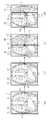
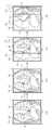
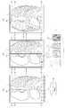
도 2에는 디스플레이부의 화면이 분할되는 예시적인 과정이 도시되어 있고, 도 3에는 엑스선 영상의 예시들로 언급될 일반 엑스선 영상(general), 연조직 엑스선 영상(soft), 뼈 엑스선 영상(bone) 및 컬러 엑스선 영상(color)이 도시되어 있다.FIG. 2 shows an exemplary process of dividing the screen of the display unit, and FIG. 3 shows a general X-ray image, a soft tissue X-ray image (soft), a bone X-ray image, and a color that will be referred to as examples of the X-ray image. An X-ray image (color) is shown.
도 2의 (a)를 참조하면, 디스플레이부(100)에는 대상체의 가슴부분을 촬영한 일반 엑스선 영상이 표시되어 있고, 화면을 분할하기 위해 마련된 마커(110, 111)가 디스플레이부(100)의 좌우에 표시되어 있다. 엑스선 영상은 의료 영상의 일 예일 뿐, 디스플레이부(100)에 표시될 수 있는 의료 영상은 엑스선 영상에 한정되지 않고, 초음파 장치, 컴퓨터 단층 촬영장치, 자기공명영상장치, 양전자 단층 촬영장치, 단일광자 단층촬영장치와 같은 다른 종류의 모달리티에서 촬영한 영상도 포함한다.Referring to FIG. 2A, a general X-ray image photographing a chest of an object is displayed on the
도 2의 (a)는 일반 엑스선 영상에 해당하는 제1영상(121)이 표시되는 제1영역(120)이 디스플레이부(100)의 전체 디스플레이 영역을 차지하고 있는 화면 분할 이전의 상태를 나타낸다. 화면이 분할되기 전의 제1영역(120)에 표시되는 제1영상(121)은 다른 기법으로 촬영된 다른 영상의 비교 대상이 되는 참조영상으로 활용될 수 있다. 따라서, 도 3에 도시된 일반 엑스선 영상이 제1영상(121)으로 표시될 수 있으나, 이에 한정되지 않고, 도 3에 도시된 뼈 엑스선 영상이나 연조직 엑스선 영상 또는 컬러 엑스선 영상 등 동일한 대상체의 일정 영역을 서로 다른 기법으로 촬영하여 획득한 다양한 종류의 영상이 표시될 수 있고, 이는 사용자가 선택할 수 있다.FIG. 2A illustrates a state before screen division in which the
도 2의 (b)에 도시된 것처럼, 사용자가 디스플레이부(100)의 왼쪽에 표시된 마커(110)를 클릭하고, (c)에 도시된 것처럼 마커(110)를 우측으로 드래그하는 명령이 입력되면, 화면이 제1영역(120)과 제2영역(130)으로 분할된다. 마커(110)를 클릭하면 마커(110)를 지나는 수직 경계선(vb1)이 형성되고, 마커(110)가 드래그되면 수직 경계선(vb1)도 마커(110)의 드래그 방향으로 마커(110)와 함께 이동한다. 수직 경계선(vb1)은 제1영역(120)과 제2영역(130)의 경계에 해당한다.As shown in (b) of FIG. 2, when a user clicks the
도 2의 (a) 내지 (d)에 도시된 것처럼, 마커(110)는 화살표와 같은 심벌을 포함하여 이동 가능한 방향을 나타낼 수 있다. 그리고 마커(110)의 클릭 및 드래그는 마우스, 키보드, 트랙볼, 조이스틱, 조그셔틀, 음성인식장치, 동작인식장치와 같은 전술한 입력부(10)를 통해 수행될 수 있다.As illustrated in FIGS. 2A to 2D, the
도 2의 (c)에 도시된 것과 같이, 마커(110)를 클릭하여 디스플레이부(100)의 우측으로 드래그함으로써 수직 경계선(vb1)을 우측으로 이동시키면, 제1영역(120)의 화면점유비율이 감소하고, 새로이 생성된 제2영역(130)의 화면점유비율이 증가한다. 제1영역(120)의 화면점유비율이 감소하면서, 제1영역(120)에 표시되는 제1영상(121)이 대상체의 가슴부위를 나타내는 비율 또한 그에 비례하여 감소한다. 도 2의 (a)에는 제1영상(121)이 대상체의 전체를 나타내고 있지만, (c)에는 대상체의 가슴부위의 우측 절반 정도만 제1영상(121)으로 표시되고, 나머지 절반 정도는 제2영역(130)에 표시되는 제2영상(131)으로 표시된다. 제1영상(121)이 표시된 제1영역(120)과 제2영상(131)이 표시된 제2영역(130)의 합은 대상체 가슴부위 전체를 나타낸다.As shown in (c) of FIG. 2, when the vertical boundary line vb1 is moved to the right by clicking the
도 2(d)에 도시된 것처럼, 마커(110)를 클릭하여 제2영역(130)쪽으로 드래그함으로써 수직 경계선(vb1)을 제2영역(130)쪽으로 이동시키면, 감소된 제1영역(120)의 화면점유비율이 다시 증가하고, 증가된 제2영역(130)의 화면점유비율이 다시 감소한다. 제1영역(120)의 화면점유비율이 증가하면서, 제1영역(120)에 표시되는 제1영상(121)이 대상체의 가슴부위를 나타내는 비율 또한 그에 비례하여 증가한다. 도 2의 (c)에는 제1영상(121)이 대상체의 가슴부위 우측 절반 정도만 나타내고 있지만, (d)에는 대상체의 2/3 정도가 제1영상(121)으로 표시되고 있다. 나머지 1/3정도는 제2영역(130)에 표시되는 제2영상(131)으로 표시된다. 도 2의 (c)와 마찬가지로, 제1영상(121)이 표시된 제1영역(120)과 제2영상(131)이 표시된 제2영역(130)의 합은 대상체 가슴부위 전체를 나타낸다.As shown in FIG. 2(d), when the vertical boundary line vb1 is moved toward the
도 2(c) 및 (d)에 도시된 것처럼, 제2영상(131)은 동일한 대상체의 동일한 부위 또는 영역에 대한 엑스선 영상이지만, 뼈를 제외한 대상체의 연조직을 나타낸 연조직 엑스선 영상(도 3참조)이다. 연조직 엑스선 영상은 일 예일 뿐, 제1영상(121)이 나타내는 대상체의 영역과 동일한 영역을 다른 촬영기법으로 촬영하여 획득한 영상이면 제2영상(131)에 포함될 수 있다.2(c) and (d), the
도 2(c) 및 (d)에 도시된 것처럼, 마커(110)의 이동에 따라, 제1영역(120)과 제2영역(130)의 화면점유비율이 달라지고 그에 따라 제1영상(121)과 제2영상(131)이 나타내는 대상체 영역의 비율 또한 달라지지만, 제1영상(121)과 제2영상(131)이 나타내는 대상체 영역의 비율 변화와 무관하게 제1영상(121)과 제2영상(131)은 수직 경계선(vb1)에서 자연스럽게 정합된다. 이렇게 정합된 영상은 화면이 분할되기 전과 마찬가지로 대상체의 촬영부위 전체 영상을 나타낸다.2(c) and (d), according to the movement of the
이러한 방법을 사용하면, 사용자는 관찰하고자 하는 관심영역 근처에서 마커(110)를 이동시키면서, 관심영역을 제1영상(121)과 제2영상(131)으로 용이하고 빠르게 번갈아 가면서 확인할 수 있다. 다시 말해, 사용자는 복수의 디스플레이 장치가 아닌 하나의 디스플레이 장치에서, 서로 다른 기법으로 촬영되어 각각 고유한 정보를 가진 다른 종류의 관심영역 영상을 용이하게 끊김없이(seemless) 비교할 수 있는 것이다. 하나의 디스플레이 장치(1)에서 동일한 부위를 여러 영상을 통해 동시에 끊김없이(seemless) 확인할 수 있으므로 진단의 정확도가 향상될 수 있고, 보다 직관적인 진단이 가능하다.
Using this method, the user can easily and quickly check the region of interest alternately with the
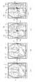
도 4에는 디스플레이부를 직접 터치하여 화면을 분할하는 예시적인 과정이 도시되어 있다. 도 4에 도시된 실시예는 도 2와 비교하여 디스플레이부(100)의 마커(110)를 손가락 또는 터치펜과 같은 터치도구를 이용하여 터치한다는 점이 다르다. 디스플레이부(100)는 터치를 통한 명령이 입력 가능하도록 공지된 다양한 터치 스크린을 사용할 수 있다. 그 외의 기술적인 내용은 도 2와 동일하므로 이하 설명을 생략한다.
4 illustrates an exemplary process of dividing a screen by directly touching the display unit. The embodiment illustrated in FIG. 4 is different from that of FIG. 2 in that the
도 5에는 디스플레이부의 화면이 분할되는 다른 예시적 과정이 도시되어 있다. 도 5에 도시된 실시예는 도 2와 비교하여 오른쪽 마커(111)를 클릭하여 이동시키는 점과 제2영역(140)에 표시되는 제2영상(141)으로 뼈 엑스선 영상(도 3 참조)이 사용된다는 점이 다르다. 그 외의 기술적 내용은 도 2와 동일하므로 이하 설명을 생략한다..5 illustrates another exemplary process of dividing the screen of the display unit. In the embodiment illustrated in FIG. 5, compared to FIG. 2, a bone X-ray image (refer to FIG. 3) includes a point moved by clicking the
일반 엑스선 영상과 연조직 엑스선 영상을 비교하여 관찰하길 원하면 도 2에 도시된 것처럼 디스플레이부(100)의 왼쪽에 표시된 마커(110)를 드래그하여 화면을 분할하고, 일반 엑스선 영상과 뼈 엑스선 영상을 비교하여 관찰하기 원하면 도 5에 도시된 것처럼 디스플레이부(100)의 오른쪽에 표시된 마커(111)를 드래그하여 화면을 분할할 수 있다. 분할된 화면의 제2영역(130, 140)에 표시되는 영상은 다른 종류의 영상으로 변경할 수 있다. 물론 제1영역(120)에 표시되는 영상도 마찬가지이다. 이에 대해서는 도 16 내지 도 19와 함께 후술한다.
If a general X-ray image and a soft tissue X-ray image are to be compared and observed, the screen is divided by dragging the
도 6에는 디스플레이부를 직접 터치하여 화면을 분할하는 다른 예시적인 과정이 도시되어 있다. 도 6에 도시된 실시예는 도 5와 비교하여 디스플레이부(100)의 마커(111)를 손가락 또는 터치펜과 같은 터치도구를 이용하여 터치한다는 점이 다르다. 디스플레이부(100)는 터치를 통한 명령이 입력 가능하도록 공지된 다양한 터치 스크린을 사용할 수 있다. 그 외의 기술적인 내용은 동일하므로 이하 설명을 생략한다.
6 illustrates another exemplary process of dividing a screen by directly touching the display unit. The embodiment illustrated in FIG. 6 is different from that of FIG. 5 in that the
도 7에는 디스플레이부의 화면이 세 개의 영역으로 분할되는 예시적인 과정이 도시되어 있다.7 illustrates an exemplary process in which the screen of the display unit is divided into three areas.
도 7의 (a) 내지 (d)는 도 2의 (a) 내지 (d)와 동일하므로 그 설명을 생략한다.7A to 7D are the same as those of FIG. 2A to 2D, so the description thereof will be omitted.
도 7(e)에 도시된 것처럼, 디스플레이부(100)의 오른쪽에 표시된 마커(111)를 클릭하고, (f)에 도시된 것처럼 마커(111)를 클릭한 채 왼쪽으로 드래그하면, 화면이 중앙의 제1영역(120)과 좌우의 분리된 제2영역(130) 및 제3영역(160)으로 분할된다. 마커(111)를 클릭하면 마커(111)를 지나는 수직 경계선(vb2)이 생성되고, 마커(111)를 드래그하면 수직 경계선(vb2)도 마커(111)의 드래그 방향으로 마커(111)와 함께 이동한다.As shown in FIG. 7(e), if the
도 7의 (f)에 도시된 것처럼, 디스플레이부(100)의 오른쪽에 표시된 마커(111)를 클릭하여 드래그하면, 제1영역(120)과 새로 생성된 제3영역(160)의 경계에 해당하는 새로운 수직 경계선(vb2)이 생성되고, 수직 경계선(vb2)은 드래그 방향으로 마커(111)와 함께 이동한다. 디스플레이부(100)의 오른쪽에 표시된 마커(111)를 클릭하여 디스플레이부(100)의 왼쪽으로 드래그함으로써 새로운 수직 경계선(vb2)을 왼쪽으로 이동시키면, 제1영역(120)이 디스플레이부(100)의 화면을 점유하는 비율이 감소하고, 새로이 생성된 제3영역(160)의 화면점유비율이 증가한다. 제1영역(120)의 화면점유비율이 감소하면서, 제1영역(120)에 표시되는 제1영상(121)이 대상체를 나타내는 비율 또한 그에 비례하여 감소한다. 도 7의 (e)에는 제1영상(121)이 대상체의 2/3 정도를 나타내고 있지만, (f)에는 대상체의 1/3 정도만 제1영상(121)으로 표시되고 있다. 대상체의 나머지 1/3정도는 새로 생성된 제3영역(160)의 제3영상(161)으로 표시되고 있다. 제1영상(121)이 표시된 제1영역(120), 제2영상(131)이 표시된 제2영역(130) 및 제3영상(161)의 제3영역(160)의 합은 대상체의 가슴부위 전체를 나타내고, 제1영상(121) 내지 제3영상(161)은 정합되어 대상체의 가슴부위 전체가 끊김 없이 보이도록 표시된다.As shown in (f) of FIG. 7, when the
분할된 각 영역에 표시된 영상을 보면, 도 7의 (f)에 도시된 것처럼, 화면 좌측의 제2영역(130)에는 대상체의 연조직 엑스선 영상이 표시되고, 중앙의 제1영역(120)에는 대상체의 일반 엑스선 영상이 표시되며, 우측의 제3영역(160)에는 대상체의 뼈 엑스선 영상이 표시된다. 다시 말해, 도 7의 (f)에 도시된, 분할된 세 개의 영역에 표시되는 영상은 동일한 대상체의 동일한 부위에 대한 엑스선 영상이지만, 서로 다른 촬영기법으로 촬영하여 대상체의 서로 다른 특징을 나타낸다. 하지만, 서로 다른 영역에 표시되는 영상은 반드시 다른 기법으로 촬영된 영상일 필요는 없다. 예를 들어 도 7의 (f)의 제2영역(130) 및 제3영역(160)에 표시되는 영상은 동일한 기법으로 촬영된 영상(일 예로 연조직 엑스선 영상 또는 뼈 엑스선 영상)일 수도 있다.Looking at the images displayed in each divided area, as shown in FIG. 7(f), an X-ray image of the soft tissue of the object is displayed in the
마커(110, 111)의 이동에 따라, 제1영역(120), 제2영역(130) 및 제3영역(160)의 화면점유비율이 달라지고 그에 따라 제1영상(121), 제2영상(131) 및 제3영상(161)이 나타내는 대상체의 비율 또한 달라지지만, 제1영상(121), 제2영상(131) 및 제3영상(161)이 나타내는 대상체의 비율 변화와 무관하게 제1영상(121), 제2영상(131) 및 제3영상(161)은 수직 경계선(vb1, vb2)에서 자연스럽게 정합된다. 이렇게 정합된 영상은 화면이 분할되기 전과 마찬가지로 대상체의 촬영부위 전체 영상을 나타낸다.According to the movement of the
앞서 설명한 것처럼, 이러한 방법을 활용하면 사용자는 관찰하고자 하는 관심영역 근처에서 도 7에 도시된 것처럼 두 개의 마커(110, 111)를 이동시키면서, 관심영역을 제1영상(121)과 제2영상(131) 및 제3영상(161)으로 용이하고 빠르게 번갈아 가면서 확인할 수 있다. 다시 말해, 사용자는 복수의 디스플레이 장치가 아닌 하나의 디스플레이 장치에서, 서로 다른 기법으로 촬영되어 각각 고유한 정보를 가진 다른 종류의 영상으로 정합된 관심영역의 영상을 쉽게 끊김없이 교번하여 비교할 수 있는 것이다.As described above, if this method is used, the user moves the two
도 2 및 도 7에는 각각 화면이 두 개의 영역과 세 개의 영역으로 분할된 것이 도시되어 있으나, 그 이상의 영역으로 분할될 수 있음은 물론이다. 이와 같이 하나의 디스플레이 장치에서 여러 영역으로 분할된 화면을 통해 대상체의 동일한 부위를 여러 영상을 통해 동시에 확인할 수 있으므로 진단의 정확도가 향상될 수 있고, 보다 직관적인 진단이 가능하다.
2 and 7 show that the screen is divided into two areas and three areas, respectively, it goes without saying that the screen may be divided into more areas. In this way, since the same part of the object can be simultaneously checked through multiple images through a screen divided into multiple areas on one display device, the accuracy of diagnosis can be improved, and a more intuitive diagnosis can be performed.
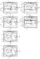
도 8에는 디스플레이부의 화면이 세 개의 영역으로 분할되는 다른 예시적인 과정이 도시되어 있다.8 illustrates another exemplary process in which the screen of the display unit is divided into three areas.
도 8에 도시된 실시예는 도 7과 비교하여 디스플레이부(100)의 마커(110, 111)를 손가락 또는 터치펜과 같은 터치도구를 이용하여 터치한다는 점이 다르다. 디스플레이부(100)는 터치를 통한 명령이 입력 가능하도록 공지된 다양한 터치 스크린을 사용할 수 있다. 그 외의 기술적인 내용은 도 7과 동일하므로 이하 설명을 생략한다.
The embodiment illustrated in FIG. 8 is different from that of FIG. 7 in that the
도 9에는 디스플레이부의 화면이 상하로 분할되는 과정이 예시적으로 도시되어 있다.9 illustrates a process in which the screen of the display unit is divided up and down by way of example.
도 9의 (a)를 참조하면, 디스플레이부(100)에는 대상체의 가슴부분을 촬영한 일반 엑스선 영상이 표시되어 있고, 화면을 분할하기 위해 마련된 마커(112)가 디스플레이부(100) 화면의 상부에 표시되어 있다.Referring to (a) of FIG. 9, a general X-ray image photographing a chest of an object is displayed on the
도 9의 (b)에 도시된 것처럼, 디스플레이부(100) 화면의 상부에 표시된 마커(112)를 클릭하고, (c)에 도시된 것처럼 마커(112)를 클릭한 채 아래로 드래그하면, 화면이 제1영역(120)과 제2영역(150)으로 분할된다. 마커(112)를 클릭하면 마커(112)를 지나는 수평 경계선(hb1)이 생성되고, 마커(112)를 드래그하면 수평 경계선(hb1)도 마커(112)의 드래그 방향으로 마커(112)와 함께 이동한다. 수평 경계선(hb1)은 제1영역(120)과 제2영역(150)의 경계에 해당한다.As shown in (b) of FIG. 9, if the
마커(112)를 클릭하여 디스플레이부(100)의 아래로 드래그함으로써 수평 경계선(hb1)을 아래로 이동시키면, 제1영역(120)이 디스플레이부(100)의 화면을 점유하는 비율이 감소하고, 새로이 생성된 제2영역(150)의 화면점유비율이 증가한다. 제1영역(120)의 화면점유비율이 감소하면서, 제1영역(120)에 표시되는 제1영상(121)이 대상체의 가슴부위를 나타내는 비율 또한 그에 비례하여 감소한다. 도 9의 (a)에는 제1영상(121)이 대상체의 가슴부위 전체를 나타내고 있지만, (c)에는 대상체의 가슴부위 하측 절반 정도만 제1영상(121)으로 표시되고 있다. 나머지 절반 정도는 제2영역(150)에 표시되는 제2영상(151)으로 표시된다. 제1영상(121)이 표시된 제1영역(120)과 제2영상(151)이 표시된 제2영역(150)의 합은 대상체의 가슴부위 전체를 나타내고, 제1영상(121) 및 제2영상(131)은 정합되어 대상체의 가슴부위 전체가 끊김 없이 보이도록 표시된다.When the horizontal boundary line hb1 is moved downward by clicking the
도 9(d)에 도시된 것처럼, 마커(112)를 클릭하여 제2영역(150)쪽으로 드래그함으로써 수평 경계선(hb1)을 제2영역(150)쪽으로 이동시키면, 감소된 제1영역(120)의 화면점유비율이 다시 증가하고, 증가된 제2영역(150)의 화면점유비율이 다시 감소한다. 제1영역(120)의 화면점유비율이 증가하면서, 제1영역(120)에 표시되는 제1영상(121)이 대상체를 나타내는 비율 또한 그에 비례하여 증가한다. 도 9의 (c)에는 제1영상(121)이 대상체의 하측 절반 정도만 나타내고 있지만, (d)에는 대상체의 2/3 정도가 제1영상(121)으로 표시되고 있다. 나머지 1/3정도는 제2영역(150)에 표시되는 제2영상(151)으로 표시된다. 하지만 도 9의 (c)와 마찬가지로 제1영상(121)과 제2영상(151)의 합은 대상체의 가슴부위 전체를 나타낸다.As shown in FIG. 9(d), when the horizontal boundary line hb1 is moved toward the
도 9(c) 및 (d)에 도시된 것처럼, 제2영상(151)은 동일한 대상체의 동일한 부위에 대한 엑스선 영상이지만, 그레이 영상이 아닌 컬러 엑스선 영상(도 3 참조)이다. 컬러 엑스선 영상은 일 예일 뿐, 제1영상(121)이 나타내는 대상체의 부위와 동일한 부위를 다른 촬영기법으로 촬영하여 획득한 영상이면 제2영상(151)에 포함될 수 있다.9(c) and (d), the
도 9(c) 및 (d)에 도시된 것처럼, 마커(112)의 이동에 따라, 제1영역(120)과 제2영역(150)의 화면점유비율이 달라지고 그에 따라 제1영상(121)과 제2영상(151)이 나타내는 대상체 부위의 비율 또한 달라지지만, 제1영상(121)과 제2영상(151)이 나타내는 대상체 부위의 비율 변화와 무관하게 제1영상(121)과 제2영상(151)은 수평 경계선(hb1)에서 자연스럽게 정합된다. 이렇게 정합된 영상은 화면이 분할되기 전과 마찬가지로 대상체의 촬영부위 전체 영상을 나타낸다. 화면의 상부에 표시된 마커(112)와 더불어 도면에는 도시하지 않았지만 화면의 좌우 측에 표시된 도 7의 마커(110, 111)를 함께 조작하여 화면을 4개 또는 6개의 영역으로 분할할 수도 있다.
9(c) and (d), according to the movement of the
도 10에는 디스플레이부의 화면이 상하로 분할되는 다른 예시적인 과정이 도시되어 있다. 도 10에 도시된 실시예는 도 9와 비교하여 디스플레이부(100)의 마커(112)를 손가락 또는 터치펜과 같은 터치도구를 이용하여 터치한다는 점이 다르다. 디스플레이부(100)는 터치를 통한 명령이 입력 가능하도록 공지된 다양한 터치 스크린을 사용할 수 있다. 그 외의 기술적인 내용은 도 9와 동일하므로 이하 설명을 생략한다.
10 illustrates another exemplary process in which the screen of the display unit is divided up and down. The embodiment illustrated in FIG. 10 is different from that of FIG. 9 in that the
도 11 내지 도 14에는 디스플레이부의 화면을 분할하는 다른 실시예가 도시되어 있다.11 to 14 illustrate another embodiment of dividing the screen of the display unit.
도 11의 (a)를 참조하면, 디스플레이부(100)에는 대상체의 가슴부분을 촬영한 일반 엑스선 영상이 표시되어 있고, 화면을 분할하기 위한 별도의 마커가 도시되어 있지 않다.Referring to FIG. 11A, a general X-ray image photographing a chest of an object is displayed on the
도 11의 (b)에 도시된 것처럼, 화면의 임의의 위치를 클릭하면, 도 11의 (c)에 도시된 것처럼 클릭지점(cp1)을 지나는 수직 경계선(vb1)이 생성되고, 생성된 수직 경계선(vb1)을 경계로 하는 제1영역(120)과 제2영역(130)으로 화면이 분할된다. 도면에는 제1영역(120)과 제2영역(130)의 경계선(vb1)이 수직으로 생성되는 것이 도시되어 있으나 수평 또는 대각선으로 경계선이 형성될 수도 있다. 사용자가 원하는 경계선을 선택할 수 있도록, 각각의 경계선마다 해당 경계선을 선택하기 위한 서로 다른 조작방법이 미리 설정되어 저장될 수 있다. 예를 들어, 클릭 지점(cp1)을 한 번 클릭하면 수직 경계선이 생성되고 두 번 클릭하면 수평 경계선이 생성되도록 미리 설정될 수 있다. 분할된 제1영역(120)과 제2영역(130)에 표시되는 대상체의 영상에 대한 설명은 도 2에서의 설명과 동일하므로 생략한다.As shown in (b) of FIG. 11, when an arbitrary position on the screen is clicked, as shown in (c) of FIG. 11, a vertical boundary line vb1 passing through the click point cp1 is created, and the generated vertical boundary line The screen is divided into a
제1영역(120)과 제2영역(130)의 화면점유비율을 조절하기 위해, 도 2에서는 마커를 드래그하였으나, 본 실시예에서는 경계선(vb1)이 형성되길 원하는 지점(cp1)을 단순히 클릭함으로써 제1영역(120)과 제2영역(130)의 화면점유비율을 조절할 수 있다. 보다 자세히 설명하면, 도 11의 (d)에 도시된 것처럼, 클릭지점(cp1)과 다른 지점(cp2)을 클릭하면, 도 11의 (c)에 도시된 수직 경계선(vb1)은 사라지고, 새로운 클릭지점(cp2)을 지나는 새로운 수직 경계선(vb1)이 형성된다. 화면은 새롭게 형성된 수직 경계선(vb1)을 경계로 하여 제1영역(120)과 제2영역(130)이 분할된다. 도 11의 (c)와 비교하면, (d)에서의 제1영역(120)의 화면점유비율은 감소하고 제2영역(130)의 화면점유비율은 증가한다.In order to adjust the screen occupancy ratio of the
도 11의 (d)에 도시된 것처럼, 새로운 클릭지점(cp2)을 한 번 클릭하면 새로운 클릭지점(cp2)을 지나는 수직 경계선(vb1)이 새롭게 형성된다. 별도로 도시하지는 않았으나 새로운 클릭지점(cp2)을 계속 클릭하고 있으면, 도 11의 (c)에 도시된 수직 경계선(vb1)이 도 11의 (d)에 도시된 수직 경계선(vb1)의 위치로 이동하는 방식으로 새로운 수직 경계선(vb1)이 생성될 수도 있다.As shown in (d) of FIG. 11, when a new click point cp2 is clicked once, a vertical boundary line vb1 passing through the new click point cp2 is newly formed. Although not shown separately, if the new click point cp2 is continuously clicked, the vertical boundary line vb1 shown in FIG. 11(c) moves to the position of the vertical boundary line vb1 shown in FIG. 11(d). In this way, a new vertical boundary line vb1 may be created.
도 11의 방법과 달리, 도 12의 (d)에 도시된 것처럼, 도 12의 (c)에 도시된 클릭지점(cp1)에서 도 12의 (d)에 도시된 클릭지점(cp1)으로 커서를 드래그하면, 드래그 되는 커서를 따라 (c)에 도시된 수직 경계선(vb1)이 (d)에 도시된 수직 경계선(vb1)의 위치로 이동하는 방식으로 새로운 수직 경계선(vb1)이 생성될 수도 있다. 다시 말해, 도 11의 (d)처럼, 새로운 클릭지점(cp2)을 생성하는 것이 아니라 도 12의 (c)에 도시된 클릭지점(cp1)을 이동시키는 개념이다.Unlike the method of FIG. 11, as shown in FIG. 12(d), the cursor is moved from the click point cp1 shown in FIG. 12(c) to the click point cp1 shown in FIG. 12(d). When dragging, a new vertical boundary line vb1 may be generated in a manner in which the vertical boundary line vb1 shown in (c) moves to the position of the vertical boundary line vb1 shown in (d) along the dragged cursor. In other words, as shown in (d) of FIG. 11, the concept of moving the click point cp1 shown in (c) of FIG. 12 is not creating a new click point (cp2).
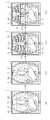
도 13과 도 14에는 도 11과 도 12와 달리 터치를 통해 도 11과 도 12에 도시된 것과 동일한 화면 분할이 일어나는 것이 도시되어 있다. 도 13 및 도 14에 도시된 실시예는 도 11 및 도 12와 비교하여 디스플레이부(100)를 손가락 또는 터치펜과 같은 터치도구를 이용하여 터치한다는 점이 다르다. 디스플레이부(100)는 터치를 통한 명령이 입력 가능하도록 공지된 다양한 터치 스크린을 사용할 수 있다. 그 외의 기술적인 내용은 도 11 및 도 12와 동일하므로 이하 설명을 생략한다.13 and 14, unlike FIGS. 11 and 12, the same screen division as those shown in FIGS. 11 and 12 through a touch is illustrated. The embodiments shown in FIGS. 13 and 14 are different from those of FIGS. 11 and 12 in that the
도 2 내지 도 14에는 엑스선 장치로 획득한 여러 종류의 영상들이 제1영역(120)과 제2영역(130)에 표시되는 것이 도시되어 있으나, 동일한 대상체의 동일한 부위를 서로 다른 종류의 모달리티로 촬영하여 획득한 영상들을 제1영역(120)과 제2영역(130)에 표시하는 것도 가능하다. 예를 들면, CT와 PET로 각각 뇌의 동일한 횡단면을 촬영하고, 제1영역(120)에는 CT로 촬영한 영상을, 제2영역(130)에는 PET로 촬영한 영상을 표시할 수도 있다. 이 경우, 사용자는 다른 종류의 모달리티로 촬영한 동일한 대상체의 동일한 부위에 대한 여러 영상을 하나의 디스플레이 장치에서 동시에 끊김 없이 확인할 수 있기 때문에 보다 효율적이고 정확한 진단이 가능하다.2 to 14 show that various types of images acquired by the X-ray apparatus are displayed in the
도 15에는 디스플레이부에 마커와 텍스트가 함께 표시되는 실시예가 도시되어 있다.15 illustrates an embodiment in which a marker and text are displayed together on a display unit.
디스플레이부(100)에 표시된 마커(110, 111, 112)를 이동시킬 경우, 분할되는 화면의 다른 영역(130, 160, 150)(도 7 내지 도 10 참조)에 표시되는 대상체 영상의 종류를 사용자가 미리 알 수 있도록, 마커(110, 111, 112)와 다른 영상(131, 161, 151)의 특징을 나타내는 텍스트가 디스플레이부(100)의 화면에 함께 표시된다.When moving the
도 15에 도시된 것처럼, 디스플레이부(100)의 좌측 마커(110)에는 "soft"라는 텍스트를 함께 표시하여, 해당 마커(110)를 이동시킬 경우, 연조직 엑스선 영상이 일부 영역에 표시됨을 사용자가 알 수 있도록 하고, 디스플레이부(100)의 우측 마커(111)에는 "bone"이라는 텍스트를 함께 표시하여, 해당 마커(111)를 이동시킬 경우 뼈 엑스선 영상이 일부 영역에 표시됨을 사용자가 알 수 있도록 한다. 그리고 디스플레이부(100)의 상부 마커(112)에는 "color"라는 텍스트를 함께 표시하여, 해당 마커(112)를 이동시킬 경우 컬러 엑스선 영상이 일부 영역에 표시됨을 사용자가 알 수 있도록 한다.As shown in FIG. 15, when the text “soft” is displayed on the
텍스트를 마커(110, 111, 112)와 병기하여 표시하는 것은 일 예이고, 썸네일을 마커(110, 111, 112)와 함께 병기할 수도 있다. 다른 영역(130, 160, 150)에 어떤 종류의 영상이 표시되는지 미리 알 수 있도록 하는 표시이면 본 실시예의 범주에 포함된다.
Displaying text in parallel with the
도 16 내지 도 20에는 분할된 제1영역과 제2영역에 표시되는 제1영상과 제2영상을 다른 영상으로 변경하는 다양한 실시예가 도시되어 있다.16 to 20 illustrate various embodiments of changing a first image and a second image displayed in the divided first region and the second region into different images.
도 16을 참조하면, 제1영역(120)과 제2영역(130)의 하단에는 복수의 썸네일(tn1, tn2, tn3, tn4)이 표시되는 창(123, 133)이 형성될 수 있다. 썸네일(tn1, tn2, tn3, tn4)이 표시되는 창(123, 133)은 각 영역의 하단 뿐만 아니라 상단 등 다른 위치에 형성될 수도 있다. 썸네일(tn1, tn2, tn3, tn4)은 동일한 대상체의 동일한 부위를 다양한 기법으로 촬영한 엑스선 영상들의 썸네일일 수 있다. 썸네일(tn1, tn2, tn3, tn4)이 나타내는 엑스선 영상들은 메모리(20)(도 1 참조)에 미리 저장될 수 있다. 연조직 엑스선 영상의 썸네일(tn1), 일반 엑스선 영상의 썸네일(tn2), 뼈 엑스선 영상의 썸네일(tn3), 컬러 엑스선 영상의 썸네일(tn4) 등 다양한 엑스선 영상의 썸네일들이 표시될 수 있다.Referring to FIG. 16,
도 16(b) 및 도 17(b)를 참조하면, 제1영역(120)에는 뼈 엑스선 영상이, 제2영역(120)에는 연조직 엑스선 영상이 표시되어 있는데, 사용자가 일반 엑스선 영상과 뼈 엑스선 영상을 비교하고자 할 경우, 제2영역(130)의 하단에 표시된 썸네일(tn1, tn2, tn3, tn4) 중 일반 엑스선 영상의 썸네일(tn2)을 클릭하거나 터치할 수 있다. 일반 엑스선 영상의 썸네일(tn2)이 클릭되거나 터치되면, 제2영역(130)에 표시된 연조직 엑스선 영상은 일반 엑스선 영상으로 변경된다. 변경된 일반 엑스선 영상과 제1영역(120)의 뼈 엑스선 영상은 경계선(vb1)에서 자연스럽게 정합되고 정합된 영상은 동일한 대상체의 동일한 부위를 나타낸다.16(b) and 17(b), a bone X-ray image is displayed in the
도면에는 도시되지 않았으나, 사용자가 연조직 엑스선 영상과 컬러 엑스선 영상을 비교하고자 할 경우, 제1영역(120)의 하단에 표시된 썸네일(tn1, tn2, tn3, tn4) 중 컬러 엑스선 영상의 썸네일(tn4)을 클릭하거나 터치할 수 있다. 컬러 엑스선 영상의 썸네일(tn4)이 클릭되거나 터치되면, 제1영역(120)에 표시된 뼈 엑스선 영상은 컬러 엑스선 영상으로 변경된다. 변경된 컬러 엑스선 영상과 제2영역(130)의 일반 엑스선 영상은 경계선(vb1)에서 자연스럽게 정합되고 정합된 영상은 동일한 대상체의 동일한 부위를 나타낸다.
Although not shown in the drawing, when a user wants to compare a soft tissue X-ray image and a color X-ray image, a thumbnail (tn4) of a color X-ray image among the thumbnails (tn1, tn2, tn3, tn4) displayed at the bottom of the
도 18을 참조하면, 제1영역(120)과 제2영역(130)의 하단에는 각 영역에 표시될 수 있는 엑스선 영상의 특징을 설명하는 텍스트와 텍스트를 변경할 수 있는 아이콘이 함께 표시되는 창(124, 134)이 형성될 수 있다. 텍스트 표시되는 상기 창(124, 134)은 각 영역의 하단 뿐만 아니라 상단 등 다른 위치에 형성될 수도 있다.Referring to FIG. 18, a window in which text describing the characteristics of an X-ray image that can be displayed in each area and an icon for changing the text are displayed together at the bottom of the
제1영역(120)에 표시되는 제1영상(121)을 뼈 엑스선 영상에서 연조직 엑스선 영상으로 변경하고자 할 경우, 사용자는 도 18의 (a)에 도시된 것처럼, 제1영역(120)의 하단에 형성된 창(124, 134)에서 텍스트를 변경하는 아이콘을 터치 또는 클릭하고, 도 18의 (b)에 도시된 것처럼, "soft"라는 텍스트를 터치 또는 클릭한다. 텍스트를 터치 또는 클릭하면, 도 18의 (c)에 도시된 것처럼 제1영역(120)에 표시되는 제1영상(121)이 뼈 엑스선 영상에서 연조직 엑스선 영상으로 변경된다. 변경된 연조직 엑스선 영상과 제2영역(130)의 일반 엑스선 영상은 경계선(vb1)에서 자연스럽게 정합되고 정합된 영상은 동일한 대상체의 동일한 부위를 나타낸다.
When changing the
도 19 및 도 20을 참조하면, 제1영역(120)과 제2영역(130)에는 썸네일이나 텍스트가 표시되는 별도의 창이 형성되지 않는다. 본 실시예에서 사용자는 변경하고자 하는 영상이 표시된 영역에 커서를 위치시켜 마우스의 휠을 통한 스크롤 명령이나 키보드의 방향키의 조작을 통한 명령을 통해 영상을 변경할 수 있다. 또는 마우스의 휠을 통한 스크롤 명령과 유사하게 영상을 변경하고자 하는 영역을 터치하고 아래나 위로 드래그하여 영상을 변경할 수 있다.19 and 20, separate windows for displaying thumbnails or text are not formed in the
도 19 및 도 20에 도시된 것처럼, 제2영역(130)에 커서를 위치시키고 마우스의 휠을 아래로 회전시켜 스크롤다운 명령을 입력하면, 제2영역(130)에 표시된 제2영상(131)이 메모리(20)에 저장된 엑스선 영상들로 차례로 변경된다. 변경하고자 했던 영상이 지나간 경우 사용자는 마우스 휠을 위로 회전시켜 스크롤업 명령을 입력하여 원하는 영상을 찾을 수 있다. 스크롤다운 또는 스크롤업 명령이 계속 입력되다가 원하는 영상이 제2영역(130)에 표시되어 스크롤이 멈추면, 영상이 더 이상 변경되지 않게 된다.As shown in FIGS. 19 and 20, when a cursor is positioned on the
사용자는 마우스를 통한 입력뿐만 아니라 키보드의 방향키 중 아래방향 또는 윗방향을 가리키는 방향키를 조작하여 같은 방식으로 제2영역(130)에 표시되는 영상을 변경할 수 있다. 물론 좌우 방향키를 조작하여 영상을 변경할 수도 있을 것이다. 마우스나 키보드를 일 예로 하여 설명하였으나, 전술한 다른 입력방식을 사용하여 영상을 변경하는 것도 가능하다. 또한, 사용자는 마우스나 키보드와 같은 별도의 입력부를 사용하지 않고, 손가락이나 터치펜을 사용하여 디스플레이부(100)의 화면을 직접 터치하고, 위아래로 드래그함으로써 제2영역(130)에 표시되는 영상을 변경할 수 있다.
The user may change the image displayed on the
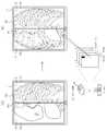
도 21 및 도 22에는 디스플레이부에 표시되는 영상을 확대하여 분할하는 예시적인 방법이 도시되어 있다. 도 21을 참조하면, 사용자는 관심영역을 확대하여 관찰하기 위해 관심영역의 확대명령을 입력할 수 있다. 도 21의 (a) 및 (b)에 도시된 것처럼, 관심영역 근처의 소정의 위치를 클릭하고 드래그하여 확대하고자 하는 영역을 지정한다. 일반적으로 드래그 라인을 대각선으로 갖는 사각형이 드래그 방향을 따라 형성되고, 이렇게 형성된 사각형 영역이 확대영역으로 지정된다.21 and 22 illustrate an exemplary method of enlarging and dividing an image displayed on the display unit. Referring to FIG. 21, a user may input an enlargement command for the region of interest to enlarge and observe the region of interest. As shown in (a) and (b) of FIG. 21, a region to be enlarged is designated by clicking and dragging a predetermined position near the region of interest. In general, a rectangle having a drag line diagonally is formed along the drag direction, and the thus formed rectangular area is designated as an enlarged area.
클릭을 이용하지 않고, 터치를 통해 직접 확대영역의 형태 및 크기를 지정할 수도 있다. 예를 들면, 도 22의 (a) 및 (b)에 도시된 것처럼, 관심영역 근처의 소정의 위치를 터치하고, 확대하고자 하는 영역의 형태를 손가락 또는 터치펜으로 그린다. 도 22(b)에는 확대영역이 원형으로 형성된 것이 도시되어 있다. 도 21 및 도 22에 도시된 확대영역을 지정하는 방법은 일 예일 뿐, 다른 다양한 방법으로 구현될 수 있을 것이다.It is also possible to directly designate the shape and size of the enlarged area through touch without using a click. For example, as shown in (a) and (b) of FIG. 22, a predetermined position near the region of interest is touched, and the shape of the region to be enlarged is drawn with a finger or a touch pen. Fig. 22(b) shows that the enlarged area is formed in a circular shape. The method of designating the enlarged area shown in FIGS. 21 and 22 is only an example, and may be implemented in various other ways.
도 21 (c) 및 도 22 (c)에 도시된 것처럼, 확대영역이 지정되기 전, 확대영역에 해당하는 부분의 영상은 확대영역의 지정이 완료되면 미리 정해진 배율로 확대되어 표시된다. 확대 배율은 다양하게 미리 설정되어 메모리(20)에 저장될 수 있고, 사용자는 원하는 확대배율을 선택하여 영상의 확대정도를 결정할 수 있다.21(c) and 22(c), before the enlarged area is designated, the image of the portion corresponding to the enlarged area is enlarged and displayed at a predetermined magnification when the designation of the enlarged area is completed. The magnification magnification may be preset in various ways and stored in the
전술한 다양한 실시예들에 설명한 것처럼 확대영역의 화면 또한 분할이 가능하다. 그리고, 분할된 영역에 서로 다른 기법으로 촬영된 동일한 대상체의 영상이 각각 표시될 수 있다. 도 21 (d) 및 도 22의 (d)를 참조하면, 화면의 임의의 위치를 클릭하거나 터치하면, 클릭지점(cpe) 또는 터치지점(tpe)을 지나는 수직 경계선(vbe)이 생성되고, 생성된 수직 경계선(vbe)을 경계로 하는 제1영역(120e)과 제2영역(130e)으로 화면이 분할된다. 도면에는 제1영역(120e)과 제2영역(130e)의 경계선(vbe)이 수직으로 생성되는 것이 도시되어 있으나 수평 또는 대각선으로 경계선이 형성될 수도 있다. 사용자가 원하는 경계선을 선택할 수 있도록, 각각의 경계선마다 해당 경계선을 선택하기 위한 서로 다른 조작방법이 미리 설정되어 저장될 수 있다. 예를 들어, 클릭 지점을 한 번 클릭하면 수직 경계선이 생성되고 두 번 클릭하면 수평 경계선이 생성되도록 미리 설정될 수 있다. 또한 확대영역에 도 2에 도시된 것처럼 마커(110, 111)가 표시되어 마커(110, 111)를 드래그 함으로써 확대영역을 분할하는 것도 물론 가능하다.As described in the various embodiments described above, the screen of the enlarged area can also be divided. In addition, images of the same object photographed by different techniques may be displayed in the divided regions, respectively. Referring to Figures 21 (d) and 22 (d), when clicking or touching an arbitrary position on the screen, a vertical boundary line (vbe) passing through the click point (cpe) or the touch point (tpe) is created, and is generated. The screen is divided into a
분할된 제1영역(120e)과 제2영역(130e)에는 동일한 대상체의 동일한 부위를 서로 다른 기법으로 촬영한 영상이 각각 표시된다. 도 21 (d)와 도 22 (d)에 도시된 것처럼, 제1영역(120e)에는 컬러 엑스선 영상이 표시될 수 있고 제2영역(130e)에는 일반 엑스선 영상이 표시될 수 있다. 제1영역(120e)과 제2영역(130e)의 화면점유비율을 조절하기 위해, 도 2에서 설명한 것처럼 마커(110, 111)를 드래그하는 방법이나 도 11 내지 도 14에 설명한 것처럼, 확대영역에서 경계선(vbe)이 형성되길 원하는 지점을 클릭하거나 터치하는 방법을 적용할 수 있다.In the divided
제1영역(120e)과 제2영역(130e)의 화면점유비율이 달라지고 그에 따라 제1영상(121e)과 제2영상(131e)이 나타내는 대상체 일정 영역의 비율이 달라져도, 제1영상(121e)과 제2영상(131e)이 나타내는 대상체 일정영역의 비율 변화와 무관하게 제1영상(121)과 제2영상(131e)은 항상 수직 경계선(vbe)에서 자연스럽게 정합된다. 또한, 확대영역의 분할된 제1영역(120e) 및 제2영역(130e)에 표시되는 제1영상(121e) 및 제2영상(131e)을, 도 16 내지 도 20에 설명한 방법을 적용하여 다른 종류의 영상으로 변경할 수도 있다.
Even if the screen occupancy ratio of the
전술한 다양한 실시예에 따라, 사용자는 관찰하고자 하는 대상체의 일정영역을 서로 다른 영상으로 용이하고 빠르게 번갈아 가면서 확인할 수 있다. 또한, 사용자는 복수의 디스플레이 장치가 아닌 하나의 디스플레이 장치에서, 관심이 있는 대상체의 일정 영역을 서로 다른 기법으로 촬영되어 각각 고유한 정보를 가진 다른 종류의 영상들의 합으로 끊김 없이 표시하고 비교할 수 있다. 하나의 디스플레이 장치에서 동일한 부위를 여러 영상을 통해 동시에 확인할 수 있으므로 진단의 정확도가 향상될 수 있고, 보다 직관적인 진단이 가능하다.According to the above-described various embodiments, a user can easily and quickly check a certain area of an object to be observed with different images alternately. In addition, a user can capture a certain area of an object of interest using different techniques in one display device rather than a plurality of display devices, and display and compare seamlessly as the sum of different types of images each having unique information. . Since the same part can be simultaneously checked through multiple images in one display device, the accuracy of diagnosis can be improved, and more intuitive diagnosis is possible.
1: 디스플레이 장치
10: 입력부
20: 메모리
100: 디스플레이부1: display device
10: input
20: memory
100: display unit
Claims (27)
Translated fromKorean상기 복수의 서로 다른 종류의 엑스선 영상 중 적어도 하나와, 상기 복수의 서로 다른 종류의 엑스선 영상에 각각 대응되는 복수의 썸네일을 함께 표시하는 디스플레이부; 및
상기 복수의 썸네일 중 하나에 대한 선택이 입력되는 입력부;를 포함하되,
상기 디스플레이부는,
상기 엑스선 영상이 표시된 화면을 상기 대상체의 일부를 나타내는 제1엑스선 영상이 표시되는 제1영역과 상기 대상체의 나머지 부분을 나타내는 제2엑스선 영상이 표시되는 제2영역으로 분할하고, 상기 복수의 썸네일 중 선택된 썸네일에 대응되는 엑스선 영상을 상기 제1영역과 상기 제2영역 중 하나에 표시하는 디스플레이 장치.A memory in which a plurality of different types of X-ray images of the same object are stored;
A display unit for simultaneously displaying at least one of the plurality of different types of X-ray images and a plurality of thumbnails respectively corresponding to the plurality of different types of X-ray images; And
Including; an input unit for inputting a selection of one of the plurality of thumbnails,
The display unit,
The screen on which the X-ray image is displayed is divided into a first area on which a first X-ray image representing a part of the object is displayed and a second area on which a second X-ray image representing the rest of the object is displayed, and among the plurality of thumbnails A display device that displays an X-ray image corresponding to the selected thumbnail on one of the first area and the second area.
상기 입력부는 상기 제1영역과 상기 제2영역의 경계를 상기 제1영역 쪽으로 이동시키는 명령을 더 입력 받고,
상기 경계를 이동시키는 명령에 따라, 상기 디스플레이부는 상기 제1영역의 화면점유비율을 감소시켜 상기 제2영역의 화면점유비율을 증가시키는 디스플레이 장치.The method of claim 1,
The input unit further receives a command to move the boundary between the first region and the second region toward the first region,
According to the command to move the boundary, the display unit increases the screen share ratio of the second region by decreasing the screen share ratio of the first region.
상기 입력부는 상기 제1영역과 상기 제2영역의 경계를 상기 제1영역 쪽으로 이동시키는 명령을 더 입력 받고,
상기 경계를 이동시키는 명령에 따라 상기 디스플레이부는 상기 제1영상이 나타내는 대상체의 비율을 감소시켜 상기 제2영상이 나타내는 대상체의 비율을 증가시키는 디스플레이 장치.The method of claim 1,
The input unit further receives a command to move the boundary between the first region and the second region toward the first region,
The display apparatus increases the ratio of the object represented by the second image by reducing the ratio of the object represented by the first image according to the command to move the boundary.
상기 입력부는,
상기 디스플레이부에 포함된 터치스크린을 포함하고,
상기 터치스크린을 통해 명령을 입력받는 디스플레이 장치.The method of claim 1,
The input unit,
Including a touch screen included in the display unit,
A display device that receives a command through the touch screen.
상기 입력부는,
키보드, 마우스, 동작인식장치, 음성인식장치, 트랙볼, 조그셔틀 및 조이스틱 중 적어도 하나를 포함하는 디스플레이 장치.The method of claim 1,
The input unit,
A display device comprising at least one of a keyboard, a mouse, a motion recognition device, a voice recognition device, a trackball, a jog shuttle, and a joystick.
상기 디스플레이부는 상기 화면 분할을 위해 마련되는 적어도 하나의 마커를 표시하고,
상기 마커가 드래그되는 경우, 상기 디스플레이부는 상기 드래그 방향으로 상기 제1영역과 상기 제2영역의 경계를 이동시켜, 상기 제1영역과 제2영역의 화면점유비율을 상대적으로 변화시키는 디스플레이 장치.The method of claim 1,
The display unit displays at least one marker provided for dividing the screen,
When the marker is dragged, the display unit moves a boundary between the first region and the second region in the drag direction to relatively change the screen occupancy ratio of the first region and the second region.
상기 디스플레이부는 상기 화면의 분할을 위해 마련되는 적어도 하나의 마커를 표시하고,
상기 마커가 상기 제1영역 쪽으로 드래그되면, 상기 디스플레이부는 상기 제1영역 쪽으로 상기 제1영역과 상기 제2영역의 경계를 이동시켜, 상기 제1영역의 화면점유비율을 감소시키고 상기 제2영역의 화면점유비율을 증가시키는 디스플레이 장치.The method of claim 1,
The display unit displays at least one marker provided for dividing the screen,
When the marker is dragged toward the first area, the display unit moves the boundary between the first area and the second area toward the first area, thereby reducing the screen occupancy ratio of the first area and A display device that increases the screen occupancy ratio.
상기 디스플레이부 화면 중 일부 지점이 선택되는 경우, 상기 디스플레이부는 상기 선택 지점을 지나는 수평선, 수직선 및 대각선 중 어느 하나를 경계로 하여 상기 화면을 제1영역과 제2영역으로 분할하고,
상기 선택지점이 드래그되는 경우, 상기 드래그 방향으로 상기 경계를 이동시켜 상기 제1영역과 제2영역의 화면 점유 비율을 상대적으로 변화시키는 디스플레이 장치.The method of claim 1,
When some points of the screen of the display unit are selected, the display unit divides the screen into a first area and a second area based on any one of a horizontal line, a vertical line, and a diagonal line passing through the selected point, and
When the selection point is dragged, the display device relatively changes the screen occupancy ratio of the first area and the second area by moving the boundary in the drag direction.
상기 디스플레이부 화면 중 제1지점이 선택되는 경우, 상기 디스플레이부는 상기 선택된 제1지점을 지나는 수평선, 수직선 및 대각선 중 어느 하나를 경계로 하여 상기 화면을 제1영역과 제2영역으로 분할하고,
상기 제1지점과 다른 제2지점이 선택되는 경우, 상기 경계를 상기 선택된 제2지점을 지나는 수평선, 수직선 및 대각선 중 어느 하나로 이동시켜 상기 제1영역과 제2영역의 화면 점유 비율을 변화시키는 디스플레이 장치.The method of claim 1,
When a first point of the screen of the display unit is selected, the display unit divides the screen into a first area and a second area based on any one of a horizontal line, a vertical line, and a diagonal line passing through the selected first point, and
When a second point different from the first point is selected, a display for changing the screen occupancy ratio of the first area and the second area by moving the border to one of a horizontal line, a vertical line, and a diagonal line passing through the selected second point Device.
상기 디스플레이부는 상기 메모리에 저장된 복수의 서로 다른 종류의 엑스선 영상의 특징을 표현한 텍스트를 상기 제1영역과 제2영역에 각각 표시하고, 상기 텍스트 중 어느 하나가 선택되면 해당 영역에 상기 텍스트에 대응하는 엑스선 영상을 표시하는 디스플레이 장치.The method of claim 1,
The display unit displays text representing the characteristics of a plurality of different types of X-ray images stored in the memory in the first area and the second area, respectively, and when one of the texts is selected, the text corresponding to the text is selected in the corresponding area. A display device that displays an X-ray image.
상기 입력부는 상기 제1엑스선 영상 또는 제2엑스선 영상의 변경명령을 더 입력받고,
상기 변경명령에 따라 상기 디스플레이부는 상기 제1영역에 표시된 제1엑스선 영상 또는 제2영역에 표시된 제2엑스선 영상을 상기 메모리에 저장된 다른 종류의 엑스선 영상으로 바꾸어 표시하는 디스플레이 장치The method of claim 1,
The input unit further receives a command to change the first X-ray image or the second X-ray image,
A display device that converts and displays a first X-ray image displayed in the first region or a second X-ray image displayed in the second region into another type of X-ray image stored in the memory according to the change command
상기 입력부는 상기 화면에 표시된 엑스선 영상 중 특정 부분에 대한 확대 명령을 더 입력받고,
상기 디스플레이부는 상기 확대 명령에 따라 상기 엑스선 영상 중 특정 부분을 확대하여 표시하되,
상기 확대된 부분에 대한 분할명령의 입력 시, 확대하여 표시된 화면을 상기 대상체의 일부를 나타내는 제1엑스선 영상이 표시되는 제1영역과 대상체의 나머지 부분을 나타내는 제2엑스선 영상이 표시되는 제2영역으로 분할하는 디스플레이 장치.
The method of claim 1,
The input unit further receives an enlargement command for a specific portion of the X-ray image displayed on the screen,
The display unit enlarges and displays a specific portion of the X-ray image according to the enlargement command,
When a division command for the enlarged portion is input, a first area in which a first X-ray image representing a part of the object is displayed and a second area in which a second X-ray image representing the rest of the object is displayed on the enlarged and displayed screen Display device divided into.
상기 복수의 썸네일 중 하나에 대한 선택을 입력 받고;
상기 엑스선 영상이 표시된 화면 중 상기 대상체의 일부를 나타내는 제1엑스선 영상이 표시되는 제1영역과 상기 대상체의 나머지 부분을 나타내는 제2엑스선 영상이 표시되는 제2영역으로 분할하고, 상기 복수의 썸네일 중 선택된 썸네일에 대응되는 엑스선 영상을 상기 제1영역과 상기 제2영역 중 하나에 표시하는 것;을 포함하는 디스플레이 장치의 영상표시방법.Simultaneously displaying at least one of a plurality of different types of X-ray images of the same object and a plurality of thumbnails respectively corresponding to the plurality of different types of X-ray images;
Receiving a selection of one of the plurality of thumbnails;
The screen on which the X-ray image is displayed is divided into a first region in which a first X-ray image representing a part of the object is displayed and a second region in which a second X-ray image representing the rest of the object is displayed, and among the plurality of thumbnails And displaying an X-ray image corresponding to the selected thumbnail on one of the first region and the second region.
상기 제1영역과 상기 제2영역의 경계를 상기 제1영역 쪽으로 이동시키는 명령을 더 입력받고;
상기 경계를 이동시키는 명령에 따라, 상기 제1영역의 화면점유비율을 감소시켜 상기 제2영역의 화면점유비율을 증가시키는 것;을 포함하는 디스플레이 장치의 영상표시방법.The method of claim 16,
Further receiving a command to move the boundary between the first region and the second region toward the first region;
And increasing the screen occupancy ratio of the second region by reducing the screen occupancy ratio of the first region according to the command to move the boundary.
상기 제1영역과 상기 제2영역의 경계를 상기 제1영역 쪽으로 이동시키는 명령을 더 입력받고;
상기 경계를 이동시키는 명령에 따라, 상기 제1엑스선 영상이 나타내는 대상체의 비율을 감소시켜 상기 제2엑스선 영상이 나타내는 대상체의 비율을 증가시키는 것;을 포함하는 디스플레이 장치의 영상표시방법.The method of claim 16,
Further receiving a command to move the boundary between the first region and the second region toward the first region;
And increasing a ratio of an object represented by the second X-ray image by decreasing a ratio of an object represented by the first X-ray image according to a command for moving the boundary.
상기 화면의 분할을 위해 마련되는 적어도 하나의 마커를 상기 화면에 표시하고;
상기 마커가 드래그되는 경우, 상기 드래그 방향으로 상기 제1영역과 상기 제2영역의 경계를 이동시켜, 상기 제1영역과 제2영역의 화면 점유 비율을 상대적으로 변화시키는 것;을 포함하는 디스플레이 장치의 영상표시방법.The method of claim 16,
Displaying at least one marker provided for dividing the screen on the screen;
When the marker is dragged, moving a boundary between the first region and the second region in the drag direction to relatively change a screen occupancy ratio of the first region and the second region; How to display the image of
상기 화면 중 일부 지점이 선택되는 경우, 상기 선택지점을 지나는 수평선, 수직선 및 대각선 중 어느 하나를 경계로 하여 상기 화면을 제1영역과 제2영역으로 분할하고;
상기 선택지점이 드래그되는 경우, 상기 드래그 방향으로 상기 경계를 이동시켜 상기 제1영역과 제2영역의 화면 점유 비율을 상대적으로 변화시키는 것;을 포함하는 디스플레이 장치의 영상표시방법.The method of claim 16,
When some points of the screen are selected, dividing the screen into a first area and a second area based on any one of a horizontal line, a vertical line, and a diagonal line passing through the selected point;
And when the selection point is dragged, moving the boundary in the dragging direction to relatively change a screen occupancy ratio of the first area and the second area.
상기 화면 중 제1지점이 선택되는 경우, 상기 선택된 제1지점을 지나는 수평선, 수직선 및 대각선 중 어느 하나를 경계로 하여 상기 화면을 제1영역과 제2영역으로 분할하고;
상기 제1지점과 다른 제2지점이 선택되는 경우, 상기 경계를 상기 선택된 제2지점을 지나는 수평선, 수직선 및 대각선 중 어느 하나로 이동시켜 상기 제1영역과 제2영역의 화면 점유 비율을 변화시키는 것;을 포함하는 디스플레이 장치의 영상표시방법.The method of claim 16,
When a first point of the screen is selected, dividing the screen into a first area and a second area based on any one of a horizontal line, a vertical line, and a diagonal line passing through the selected first point;
When a second point different from the first point is selected, changing the screen occupancy ratio of the first area and the second area by moving the boundary to one of a horizontal line, a vertical line, and a diagonal line passing through the selected second point An image display method of a display device comprising;
상기 디스플레이 장치의 메모리에 저장된 복수의 서로 다른 종류의 엑스선 영상의 특징을 표현한 텍스트를 상기 제1영역과 제2영역에 각각 표시하고;
상기 텍스트 중 어느 하나가 선택되면 해당 영역에 상기 텍스트에 대응하는 엑스선 영상을 표시하는 것;을 포함하는 디스플레이 장치의 영상표시방법.The method of claim 16,
Displaying texts representing characteristics of a plurality of different types of X-ray images stored in a memory of the display device in the first area and the second area, respectively;
And displaying an X-ray image corresponding to the text in a corresponding area when any one of the texts is selected.
상기 제1엑스선 영상 또는 제2엑스선 영상의 변경명령을 입력받고;
상기 변경명령에 따라, 상기 제1영역에 표시된 제1엑스선 영상 또는 제2영역에 표시된 제2엑스선 영상을 상기 디스플레이 장치의 메모리에 저장된 다른 종류의 엑스선 영상으로 바꾸어 표시하는 것;을 포함하는 디스플레이 장치의 영상표시방법.The method of claim 16,
Receiving a command to change the first X-ray image or the second X-ray image;
And displaying a first X-ray image displayed in the first region or a second X-ray image displayed in the second region in response to the change command with another type of X-ray image stored in the memory of the display device. How to display the image of
상기 화면에 표시된 엑스선 영상 중 특정 부분에 대한 확대 명령을 더 입력 받고;
상기 확대명령에 따라 상기 엑스선 영상 중 특정 부분을 확대하여 표시하되, 상기 확대된 부분에 대한 분할명령의 입력 시, 확대하여 표시된 화면을 상기 대상체의 일부를 나타내는 제1엑스선 영상이 표시되는 제1영역과 대상체의 나머지 부분을 나타내는 제2엑스선 영상이 표시되는 제2영역으로 분할하는 것;을 포함하는 디스플레이 장치의 영상표시방법.
The method of claim 16,
Further receiving an enlargement command for a specific portion of the X-ray image displayed on the screen;
A first area in which a specific part of the X-ray image is enlarged and displayed according to the enlargement command, and when a division command for the enlarged part is input, the enlarged and displayed screen is displayed with a first X-ray image representing a part of the object And dividing the second area into a second area in which a second X-ray image representing the rest of the object is displayed.
Priority Applications (14)
| Application Number | Priority Date | Filing Date | Title |
|---|---|---|---|
| KR1020130118779AKR102244258B1 (en) | 2013-10-04 | 2013-10-04 | Display apparatus and image display method using the same |
| JP2014197324AJP2015076882A (en) | 2013-10-04 | 2014-09-26 | Display device and video display method using the same |
| IN2767DE2014IN2014DE02767A (en) | 2013-10-04 | 2014-09-26 | |
| EP16160808.8AEP3057017B1 (en) | 2013-10-04 | 2014-09-30 | Display apparatus and image display method using the same |
| EP17167330.4AEP3217305B1 (en) | 2013-10-04 | 2014-09-30 | Display apparatus and image display method using the same |
| EP20175609.5AEP3723099A1 (en) | 2013-10-04 | 2014-09-30 | Display apparatus and image display method using the same |
| EP14187055.0AEP2858000A1 (en) | 2013-10-04 | 2014-09-30 | Display apparatus and image display method using the same |
| US14/505,686US10468134B2 (en) | 2013-10-04 | 2014-10-03 | Medical imaging apparatus for displaying portions of x-ray images and method for displaying medical image |
| CN201910807347.XACN110515513B (en) | 2013-10-04 | 2014-10-08 | Display apparatus and image display method using the same |
| CN201910807427.5ACN110517758B (en) | 2013-10-04 | 2014-10-08 | Display device and image display method using the same |
| CN201410525012.6ACN104516627B (en) | 2013-10-04 | 2014-10-08 | Display device and image display method using same |
| US14/966,087US10622108B2 (en) | 2013-10-04 | 2015-12-11 | Medical imaging apparatus for displaying x-ray images of different types |
| US16/816,894US10937544B2 (en) | 2013-10-04 | 2020-03-12 | Medical imaging apparatus for displaying x-ray images of different types |
| JP2020161359AJP7045432B2 (en) | 2013-10-04 | 2020-09-25 | Medical video equipment and its control method |
Applications Claiming Priority (1)
| Application Number | Priority Date | Filing Date | Title |
|---|---|---|---|
| KR1020130118779AKR102244258B1 (en) | 2013-10-04 | 2013-10-04 | Display apparatus and image display method using the same |
Publications (2)
| Publication Number | Publication Date |
|---|---|
| KR20150041221A KR20150041221A (en) | 2015-04-16 |
| KR102244258B1true KR102244258B1 (en) | 2021-04-27 |
Family
ID=51702976
Family Applications (1)
| Application Number | Title | Priority Date | Filing Date |
|---|---|---|---|
| KR1020130118779AActiveKR102244258B1 (en) | 2013-10-04 | 2013-10-04 | Display apparatus and image display method using the same |
Country Status (6)
| Country | Link |
|---|---|
| US (3) | US10468134B2 (en) |
| EP (4) | EP3057017B1 (en) |
| JP (2) | JP2015076882A (en) |
| KR (1) | KR102244258B1 (en) |
| CN (3) | CN104516627B (en) |
| IN (1) | IN2014DE02767A (en) |
Families Citing this family (24)
| Publication number | Priority date | Publication date | Assignee | Title |
|---|---|---|---|---|
| US10198170B2 (en)* | 2014-02-12 | 2019-02-05 | Lg Electronics Inc. | Mobile terminal and control method therefor |
| WO2015126098A1 (en)* | 2014-02-24 | 2015-08-27 | Samsung Electronics Co., Ltd. | Method and apparatus for displaying content using proximity information |
| USD769278S1 (en)* | 2015-01-13 | 2016-10-18 | Comprehensive Telemedicine | Display screen with graphical user interface for auscultation points |
| CN106560827B (en)* | 2015-09-30 | 2021-11-26 | 松下知识产权经营株式会社 | Control method |
| CN107595310B (en)* | 2016-07-18 | 2020-12-15 | 上海联影医疗科技股份有限公司 | Image information display interaction device and method |
| USD830381S1 (en)* | 2017-04-18 | 2018-10-09 | Intuitive Surgical Operations, Inc. | Display screen or portion thereof with graphical user interface |
| USD844655S1 (en) | 2017-04-18 | 2019-04-02 | Intuitive Surgical Operations, Inc. | Display screen or portion thereof with graphical user interface |
| CN107622792B (en)* | 2017-08-30 | 2021-12-31 | 东软医疗系统股份有限公司 | Medical image display method and display equipment |
| CN108255405B (en) | 2018-01-19 | 2019-09-10 | Oppo广东移动通信有限公司 | User interface display method and device and terminal |
| CN108366225A (en)* | 2018-01-26 | 2018-08-03 | 蓝网科技股份有限公司 | Method, apparatus, equipment and storage medium based on the acquisition of multichannel endoscopic images |
| KR102107893B1 (en)* | 2018-02-14 | 2020-05-07 | 가톨릭대학교 산학협력단 | Medical image information reading apparatus and reading method |
| TWI686742B (en) | 2018-10-29 | 2020-03-01 | 華碩電腦股份有限公司 | Control method, electronic device and non-transitory computer readable storage medium device |
| CN109544539A (en)* | 2018-11-27 | 2019-03-29 | 南京巨鲨显示科技有限公司 | A kind of system and method for adaptive centralized displaying medical image curve |
| KR102273923B1 (en)* | 2018-12-18 | 2021-07-06 | (주)제노레이 | Apparatus And Method For Managing Medical Image Data And Treatment Data |
| CN109766069B (en)* | 2019-01-15 | 2023-05-12 | 高创(苏州)电子有限公司 | Auxiliary display method, device, electronic device, and computer-readable storage medium |
| CN111158620B (en)* | 2019-12-26 | 2020-11-24 | 成都星时代宇航科技有限公司 | Picture display method and device and terminal |
| USD953373S1 (en)* | 2020-07-15 | 2022-05-31 | Vyaire Medical, Inc. | Display screen with graphical icon |
| CN112954441B (en)* | 2021-03-02 | 2023-06-06 | 北京字节跳动网络技术有限公司 | Video editing and playing method, device, equipment, medium |
| US11620039B2 (en)* | 2021-03-02 | 2023-04-04 | Builder Homesite, Inc. | Performant configuration user interface |
| CN113946261B (en)* | 2021-08-30 | 2023-12-05 | 福建中红信创科技有限公司 | Man-machine interaction display method and system |
| USD1095545S1 (en)* | 2021-09-28 | 2025-09-30 | Annalise-Ai Pty Ltd | Display screen or portion thereof with a transitional graphical user interface for presenting AI predictions of two-dimensional radioanatomy images |
| CN114816115B (en)* | 2022-04-13 | 2023-01-17 | 安徽宝信信息科技有限公司 | Screen auxiliary assembly for education and teaching |
| KR102755019B1 (en)* | 2022-12-26 | 2025-01-21 | 주식회사 레이언스 | X-ray image processing apparatus and system |
| CN115793912B (en)* | 2023-02-02 | 2023-05-26 | 苏州一目万相科技有限公司 | Image display method, image display device, and readable storage medium |
Citations (3)
| Publication number | Priority date | Publication date | Assignee | Title |
|---|---|---|---|---|
| US20060020903A1 (en) | 2004-07-26 | 2006-01-26 | Shih-Yang Wang | Window split system and method |
| US20110157154A1 (en) | 2009-12-30 | 2011-06-30 | General Electric Company | Single screen multi-modality imaging displays |
| US20120294589A1 (en) | 2001-02-22 | 2012-11-22 | Sony Electronics Inc. | Digital video editing system including multiple viewing windows of a same image |
Family Cites Families (49)
| Publication number | Priority date | Publication date | Assignee | Title |
|---|---|---|---|---|
| US5142275A (en)* | 1984-12-10 | 1992-08-25 | General Electric Company | Method and means for manipulating images in a video display |
| JPS63223968A (en)* | 1987-03-13 | 1988-09-19 | Jeol Ltd | image display device |
| JP2886162B2 (en)* | 1987-10-13 | 1999-04-26 | 株式会社東芝 | Image display device |
| US5485371A (en)* | 1990-02-14 | 1996-01-16 | Fuji Photo Film Co., Ltd. | Method for forming energy subtraction radiation images, and method and apparatus for smoothing radiation images |
| JP3639030B2 (en)* | 1995-02-28 | 2005-04-13 | 株式会社東芝 | Image display system and image display method using the system |
| CA2175148C (en)* | 1996-04-26 | 2002-06-11 | Robert Cecco | User interface control for creating split panes in a single window |
| JP3878259B2 (en)* | 1996-11-13 | 2007-02-07 | 東芝医用システムエンジニアリング株式会社 | Medical image processing device |
| US6448956B1 (en)* | 1997-10-31 | 2002-09-10 | Eastman Kodak Company | Systems and methods for direct image manipulation |
| US6239799B1 (en)* | 1998-06-23 | 2001-05-29 | International Business Machines Corporation | Method and system for providing a splitter bar control |
| US6195094B1 (en)* | 1998-09-29 | 2001-02-27 | Netscape Communications Corporation | Window splitter bar system |
| WO2002067039A1 (en)* | 2001-02-19 | 2002-08-29 | Olympus Optical Co., Ltd. | Image comparing device, image comparing method and progrom having computer run image comparison |
| US6914958B2 (en)* | 2001-07-06 | 2005-07-05 | Ge Medical Systems Global Technology Company, Llc | Multi-plane acquisition in digital x-ray radiography |
| US20040077952A1 (en)* | 2002-10-21 | 2004-04-22 | Rafter Patrick G. | System and method for improved diagnostic image displays |
| US7616801B2 (en)* | 2002-11-27 | 2009-11-10 | Hologic, Inc. | Image handling and display in x-ray mammography and tomosynthesis |
| US8090429B2 (en)* | 2004-06-30 | 2012-01-03 | Siemens Medical Solutions Usa, Inc. | Systems and methods for localized image registration and fusion |
| CN100393281C (en)* | 2004-07-23 | 2008-06-11 | 株式会社东芝 | X-ray computed tomography device |
| JP4891577B2 (en)* | 2004-08-30 | 2012-03-07 | 株式会社東芝 | Medical image display device |
| EP1657679A1 (en)* | 2004-11-10 | 2006-05-17 | Agfa-Gevaert | Method of superimposing images |
| US20060098897A1 (en)* | 2004-11-10 | 2006-05-11 | Agfa-Gevaert | Method of superimposing images |
| US7885443B2 (en)* | 2005-11-14 | 2011-02-08 | Hologic, Inc. | Facilitating temporal comparison of medical images |
| WO2007062392A2 (en)* | 2005-11-23 | 2007-05-31 | Riverain Medical Group, Llc | Computer-aided diagnosis using dual-energy subtraction images |
| JP4989166B2 (en)* | 2006-09-14 | 2012-08-01 | ジーイー・メディカル・システムズ・グローバル・テクノロジー・カンパニー・エルエルシー | Diagnostic imaging equipment |
| US7942829B2 (en)* | 2007-11-06 | 2011-05-17 | Eigen, Inc. | Biopsy planning and display apparatus |
| FR2928257B1 (en)* | 2008-03-04 | 2011-01-14 | Super Sonic Imagine | ELECTRONIC SYSTEM FOR DOUBLE SCREEN DISPLAY. |
| JP5562525B2 (en)* | 2008-03-04 | 2014-07-30 | 株式会社東芝 | MEDICAL INFORMATION DISPLAY DEVICE AND MEDICAL INFORMATION DISPLAY PROGRAM |
| EP2109080A1 (en)* | 2008-04-09 | 2009-10-14 | IBBT vzw | A method and device for processing and presenting medical images |
| DE102009004898A1 (en)* | 2009-01-16 | 2010-08-19 | Siemens Aktiengesellschaft | Method for displaying two different images of a fusion image and device therefor |
| US8150708B2 (en) | 2009-02-17 | 2012-04-03 | Virtual Radiologic Corporation | Organizing medical images for display |
| US8627228B2 (en)* | 2009-05-24 | 2014-01-07 | International Business Machines Corporation | Automatic sash configuration in a GUI environment |
| US8218727B2 (en)* | 2009-09-04 | 2012-07-10 | Siemens Medical Solutions Usa, Inc. | System for medical image processing, manipulation and display |
| JP5670079B2 (en)* | 2009-09-30 | 2015-02-18 | 富士フイルム株式会社 | MEDICAL IMAGE DISPLAY DEVICE AND METHOD, AND PROGRAM |
| US8687860B2 (en)* | 2009-11-24 | 2014-04-01 | Penrad Technologies, Inc. | Mammography statistical diagnostic profiler and prediction system |
| KR101430121B1 (en)* | 2010-04-06 | 2014-08-14 | 삼성전자주식회사 | Apparatus of Processing Images in Multi-Energy X-ray System and Method for Processing the Images |
| JP2011224086A (en)* | 2010-04-16 | 2011-11-10 | Morita Mfg Co Ltd | Image processor, x-ray radiographing apparatus, image display method, image comparison method, and image display program |
| US8971493B2 (en)* | 2010-09-08 | 2015-03-03 | Siemens Medical Solutions Usa, Inc. | System for image scanning and acquisition with low-dose radiation |
| EP2617026A4 (en)* | 2010-09-16 | 2015-03-11 | Omnyx LLC | Digital pathology image manipulation |
| US20120133600A1 (en)* | 2010-11-26 | 2012-05-31 | Hologic, Inc. | User interface for medical image review workstation |
| JP5102888B2 (en)* | 2011-03-23 | 2012-12-19 | 日立アロカメディカル株式会社 | Bone diagnostic image display device |
| JP6039203B2 (en)* | 2011-05-23 | 2016-12-07 | キヤノン株式会社 | Image output apparatus, image output apparatus control method, and program |
| JP5628092B2 (en)* | 2011-05-25 | 2014-11-19 | 富士フイルム株式会社 | Image processing apparatus, radiation image capturing system, image processing program, and operation method of image processing apparatus |
| JP5306422B2 (en)* | 2011-07-19 | 2013-10-02 | 株式会社東芝 | Image display system, apparatus, method, and medical image diagnostic apparatus |
| JP5844576B2 (en)* | 2011-08-31 | 2016-01-20 | サイバネットシステム株式会社 | Image generating apparatus, method, and program |
| KR101337339B1 (en)* | 2011-10-21 | 2013-12-06 | 삼성전자주식회사 | X-ray imaging apparatus and control method for the same |
| KR101851239B1 (en)* | 2011-11-08 | 2018-04-23 | 삼성전자 주식회사 | Device and method for processing an image expression of wireless terminal |
| KR101474768B1 (en)* | 2011-12-21 | 2014-12-19 | 삼성전자 주식회사 | Medical device and image displaying method using the same |
| JP5745444B2 (en)* | 2012-03-05 | 2015-07-08 | 富士フイルム株式会社 | MEDICAL IMAGE DISPLAY DEVICE, MEDICAL IMAGE DISPLAY METHOD, AND MEDICAL IMAGE DISPLAY PROGRAM |
| US9877699B2 (en)* | 2012-03-26 | 2018-01-30 | Teratech Corporation | Tablet ultrasound system |
| KR20140017339A (en)* | 2012-07-31 | 2014-02-11 | 삼성전자주식회사 | X-ray imaging apparatus and method for setting imaging area of x-ray imaging apparatus |
| KR20150066963A (en)* | 2013-12-09 | 2015-06-17 | 삼성전자주식회사 | Method for arranging medical images and medical device using the method |
- 2013
- 2013-10-04KRKR1020130118779Apatent/KR102244258B1/enactiveActive
- 2014
- 2014-09-26ININ2767DE2014patent/IN2014DE02767A/enunknown
- 2014-09-26JPJP2014197324Apatent/JP2015076882A/enactivePending
- 2014-09-30EPEP16160808.8Apatent/EP3057017B1/enactiveActive
- 2014-09-30EPEP20175609.5Apatent/EP3723099A1/enactivePending
- 2014-09-30EPEP17167330.4Apatent/EP3217305B1/enactiveActive
- 2014-09-30EPEP14187055.0Apatent/EP2858000A1/ennot_activeCeased
- 2014-10-03USUS14/505,686patent/US10468134B2/enactiveActive
- 2014-10-08CNCN201410525012.6Apatent/CN104516627B/enactiveActive
- 2014-10-08CNCN201910807347.XApatent/CN110515513B/enactiveActive
- 2014-10-08CNCN201910807427.5Apatent/CN110517758B/enactiveActive
- 2015
- 2015-12-11USUS14/966,087patent/US10622108B2/enactiveActive
- 2020
- 2020-03-12USUS16/816,894patent/US10937544B2/enactiveActive
- 2020-09-25JPJP2020161359Apatent/JP7045432B2/enactiveActive
Patent Citations (3)
| Publication number | Priority date | Publication date | Assignee | Title |
|---|---|---|---|---|
| US20120294589A1 (en) | 2001-02-22 | 2012-11-22 | Sony Electronics Inc. | Digital video editing system including multiple viewing windows of a same image |
| US20060020903A1 (en) | 2004-07-26 | 2006-01-26 | Shih-Yang Wang | Window split system and method |
| US20110157154A1 (en) | 2009-12-30 | 2011-06-30 | General Electric Company | Single screen multi-modality imaging displays |
Also Published As
| Publication number | Publication date |
|---|---|
| CN110517758A (en) | 2019-11-29 |
| US20200211702A1 (en) | 2020-07-02 |
| EP2858000A1 (en) | 2015-04-08 |
| JP7045432B2 (en) | 2022-03-31 |
| EP3217305A1 (en) | 2017-09-13 |
| US10468134B2 (en) | 2019-11-05 |
| EP3057017A1 (en) | 2016-08-17 |
| JP2021020075A (en) | 2021-02-18 |
| US20160098529A1 (en) | 2016-04-07 |
| EP3723099A1 (en) | 2020-10-14 |
| CN110517758B (en) | 2024-09-20 |
| US10622108B2 (en) | 2020-04-14 |
| CN110515513A (en) | 2019-11-29 |
| KR20150041221A (en) | 2015-04-16 |
| US20150097869A1 (en) | 2015-04-09 |
| JP2015076882A (en) | 2015-04-20 |
| CN104516627A (en) | 2015-04-15 |
| IN2014DE02767A (en) | 2015-06-26 |
| US10937544B2 (en) | 2021-03-02 |
| EP3057017B1 (en) | 2021-05-26 |
| CN110515513B (en) | 2023-04-18 |
| CN104516627B (en) | 2019-09-24 |
| EP3217305B1 (en) | 2020-05-27 |
Similar Documents
| Publication | Publication Date | Title |
|---|---|---|
| KR102244258B1 (en) | Display apparatus and image display method using the same | |
| US10599883B2 (en) | Active overlay system and method for accessing and manipulating imaging displays | |
| US10324602B2 (en) | Display of 3D images | |
| CN105167793B (en) | Image display device, display control device, and display control method | |
| US9342145B2 (en) | Cursor control | |
| US11169693B2 (en) | Image navigation | |
| US10324582B2 (en) | Medical image display apparatus, method for controlling the same | |
| JP2015208602A (en) | Image display device and image display method | |
| US20150178885A1 (en) | Display apparatus and image display method using the same | |
| JP6572370B2 (en) | MEDICAL IMAGE DISPLAY DEVICE, ITS CONTROL METHOD, PROGRAM | |
| JP7172093B2 (en) | Computer program, display device, display system and display method |
Legal Events
| Date | Code | Title | Description |
|---|---|---|---|
| PA0109 | Patent application | Patent event code:PA01091R01D Comment text:Patent Application Patent event date:20131004 | |
| PG1501 | Laying open of application | ||
| A201 | Request for examination | ||
| PA0201 | Request for examination | Patent event code:PA02012R01D Patent event date:20181002 Comment text:Request for Examination of Application Patent event code:PA02011R01I Patent event date:20131004 Comment text:Patent Application | |
| E902 | Notification of reason for refusal | ||
| PE0902 | Notice of grounds for rejection | Comment text:Notification of reason for refusal Patent event date:20191211 Patent event code:PE09021S01D | |
| E90F | Notification of reason for final refusal | ||
| PE0902 | Notice of grounds for rejection | Comment text:Final Notice of Reason for Refusal Patent event date:20200626 Patent event code:PE09021S02D | |
| E701 | Decision to grant or registration of patent right | ||
| PE0701 | Decision of registration | Patent event code:PE07011S01D Comment text:Decision to Grant Registration Patent event date:20210129 | |
| GRNT | Written decision to grant | ||
| PR0701 | Registration of establishment | Comment text:Registration of Establishment Patent event date:20210420 Patent event code:PR07011E01D | |
| PR1002 | Payment of registration fee | Payment date:20210421 End annual number:3 Start annual number:1 | |
| PG1601 | Publication of registration | ||
| PR1001 | Payment of annual fee | Payment date:20240328 Start annual number:4 End annual number:4 |