KR102243037B1 - Ultrasonic diagnostic apparatus and operating method for the same - Google Patents
Ultrasonic diagnostic apparatus and operating method for the sameDownload PDFInfo
- Publication number
- KR102243037B1 KR102243037B1KR1020140031820AKR20140031820AKR102243037B1KR 102243037 B1KR102243037 B1KR 102243037B1KR 1020140031820 AKR1020140031820 AKR 1020140031820AKR 20140031820 AKR20140031820 AKR 20140031820AKR 102243037 B1KR102243037 B1KR 102243037B1
- Authority
- KR
- South Korea
- Prior art keywords
- probe
- echo signal
- signal
- gel
- ultrasound
- Prior art date
- Legal status (The legal status is an assumption and is not a legal conclusion. Google has not performed a legal analysis and makes no representation as to the accuracy of the status listed.)
- Active
Links
- 238000011017operating methodMethods0.000title1
- 239000000523sampleSubstances0.000claimsabstractdescription244
- 238000002604ultrasonographyMethods0.000claimsabstractdescription150
- 238000003745diagnosisMethods0.000claimsabstractdescription79
- 238000000034methodMethods0.000claimsabstractdescription40
- 238000001514detection methodMethods0.000claimsabstractdescription37
- 230000005540biological transmissionEffects0.000claimsdescription22
- 230000003213activating effectEffects0.000claimsdescription3
- 230000000903blocking effectEffects0.000claimsdescription2
- 238000004891communicationMethods0.000description27
- 238000010586diagramMethods0.000description15
- 238000012545processingMethods0.000description7
- 230000008569processEffects0.000description6
- 230000006870functionEffects0.000description5
- 230000033001locomotionEffects0.000description4
- 230000017531blood circulationEffects0.000description3
- 230000008859changeEffects0.000description3
- 238000005516engineering processMethods0.000description3
- 238000010295mobile communicationMethods0.000description3
- 241001465754MetazoaSpecies0.000description2
- 239000000284extractSubstances0.000description2
- 238000003384imaging methodMethods0.000description2
- 239000004973liquid crystal related substanceSubstances0.000description2
- 238000005259measurementMethods0.000description2
- 238000012986modificationMethods0.000description2
- 230000004048modificationEffects0.000description2
- 230000003287optical effectEffects0.000description2
- 208000027418Wounds and injuryDiseases0.000description1
- 210000001015abdomenAnatomy0.000description1
- 210000004204blood vesselAnatomy0.000description1
- 210000004556brainAnatomy0.000description1
- 210000000481breastAnatomy0.000description1
- 238000006243chemical reactionMethods0.000description1
- 230000006835compressionEffects0.000description1
- 238000007906compressionMethods0.000description1
- 230000006378damageEffects0.000description1
- 238000013500data storageMethods0.000description1
- 238000002059diagnostic imagingMethods0.000description1
- 239000003814drugSubstances0.000description1
- 230000000694effectsEffects0.000description1
- 230000005672electromagnetic fieldEffects0.000description1
- 210000002216heartAnatomy0.000description1
- 208000014674injuryDiseases0.000description1
- 210000004185liverAnatomy0.000description1
- 239000000463materialSubstances0.000description1
- 239000013307optical fiberSubstances0.000description1
- 210000000056organAnatomy0.000description1
- 230000010355oscillationEffects0.000description1
- 230000008439repair processEffects0.000description1
- 230000029058respiratory gaseous exchangeEffects0.000description1
- 230000004044responseEffects0.000description1
- 230000003595spectral effectEffects0.000description1
- 239000000126substanceSubstances0.000description1
- 239000010409thin filmSubstances0.000description1
- 210000004291uterusAnatomy0.000description1
Images


Classifications
- A—HUMAN NECESSITIES
- A61—MEDICAL OR VETERINARY SCIENCE; HYGIENE
- A61B—DIAGNOSIS; SURGERY; IDENTIFICATION
- A61B8/00—Diagnosis using ultrasonic, sonic or infrasonic waves
- A61B8/54—Control of the diagnostic device
- A—HUMAN NECESSITIES
- A61—MEDICAL OR VETERINARY SCIENCE; HYGIENE
- A61B—DIAGNOSIS; SURGERY; IDENTIFICATION
- A61B8/00—Diagnosis using ultrasonic, sonic or infrasonic waves
- A61B8/42—Details of probe positioning or probe attachment to the patient
- A61B8/4272—Details of probe positioning or probe attachment to the patient involving the acoustic interface between the transducer and the tissue
- A61B8/4281—Details of probe positioning or probe attachment to the patient involving the acoustic interface between the transducer and the tissue characterised by sound-transmitting media or devices for coupling the transducer to the tissue
- A—HUMAN NECESSITIES
- A61—MEDICAL OR VETERINARY SCIENCE; HYGIENE
- A61B—DIAGNOSIS; SURGERY; IDENTIFICATION
- A61B8/00—Diagnosis using ultrasonic, sonic or infrasonic waves
- A61B8/44—Constructional features of the ultrasonic, sonic or infrasonic diagnostic device
- A61B8/4477—Constructional features of the ultrasonic, sonic or infrasonic diagnostic device using several separate ultrasound transducers or probes
- A—HUMAN NECESSITIES
- A61—MEDICAL OR VETERINARY SCIENCE; HYGIENE
- A61B—DIAGNOSIS; SURGERY; IDENTIFICATION
- A61B8/00—Diagnosis using ultrasonic, sonic or infrasonic waves
- A61B8/44—Constructional features of the ultrasonic, sonic or infrasonic diagnostic device
- A61B8/4405—Device being mounted on a trolley
- A—HUMAN NECESSITIES
- A61—MEDICAL OR VETERINARY SCIENCE; HYGIENE
- A61B—DIAGNOSIS; SURGERY; IDENTIFICATION
- A61B8/00—Diagnosis using ultrasonic, sonic or infrasonic waves
- A61B8/44—Constructional features of the ultrasonic, sonic or infrasonic diagnostic device
- A61B8/4444—Constructional features of the ultrasonic, sonic or infrasonic diagnostic device related to the probe
- A—HUMAN NECESSITIES
- A61—MEDICAL OR VETERINARY SCIENCE; HYGIENE
- A61B—DIAGNOSIS; SURGERY; IDENTIFICATION
- A61B8/00—Diagnosis using ultrasonic, sonic or infrasonic waves
- A61B8/58—Testing, adjusting or calibrating the diagnostic device
- A61B8/585—Automatic set-up of the device
Landscapes
- Health & Medical Sciences (AREA)
- Life Sciences & Earth Sciences (AREA)
- Physics & Mathematics (AREA)
- Heart & Thoracic Surgery (AREA)
- Molecular Biology (AREA)
- Nuclear Medicine, Radiotherapy & Molecular Imaging (AREA)
- Pathology (AREA)
- Radiology & Medical Imaging (AREA)
- Engineering & Computer Science (AREA)
- Biomedical Technology (AREA)
- Veterinary Medicine (AREA)
- Medical Informatics (AREA)
- Biophysics (AREA)
- Surgery (AREA)
- Animal Behavior & Ethology (AREA)
- General Health & Medical Sciences (AREA)
- Public Health (AREA)
- Gynecology & Obstetrics (AREA)
- Acoustics & Sound (AREA)
- Ultra Sonic Daignosis Equipment (AREA)
Abstract
Translated fromKoreanDescription
Translated fromKorean본 발명은 초음파 진단 장치 및 그 동작방법에 관한 것으로, 더욱 구체적으로는 프로브를 자동으로 변경할 수 있는 초음파 진단 장치 및 그 동작방법에 관한 것이다.The present invention relates to an ultrasound diagnosis apparatus and an operation method thereof, and more particularly, to an ultrasound diagnosis apparatus capable of automatically changing a probe, and an operation method thereof.
초음파 진단 장치는 프로브(probe)의 트랜스듀서(transducer)로부터 생성되는 초음파 신호를 대상체로 조사하고, 대상체로부터 반사된 에코 신호의 정보를 수신하여 대상체 내부의 부위에 대한 영상을 얻는다. 특히, 초음파 진단 장치는 대상체 내부의 관찰, 이물질 검출, 및 상해 측정 등 의학적 목적으로 사용된다. 이러한 초음파 진단 장치는 X선을 이용하는 진단 장치에 비하여 안정성이 높고, 실시간으로 영상의 디스플레이가 가능하며, 방사능 피폭이 없어 안전하다는 장점이 있어서 다른 화상 진단 장치와 함께 널리 이용된다.The ultrasound diagnosis apparatus irradiates an ultrasound signal generated from a transducer of a probe to an object, receives information about an echo signal reflected from the object, and obtains an image of a portion inside the object. In particular, the ultrasound diagnosis apparatus is used for medical purposes such as observing the inside of an object, detecting foreign substances, and measuring injury. Such an ultrasound diagnosis apparatus is widely used with other image diagnosis apparatuses because of its advantages in that it has higher stability, can display images in real time, and is safe because there is no radiation exposure compared to a diagnosis apparatus using X-rays.
한편, 초음파 진단 장치는 대상체로부터 반사되는 초음파 신호의 반사 계수를 2차원 영상으로 보이는 B모드(brightness mode), 도플러 효과(doppler effect)를 이용하여 움직이는 대상체(특히, 혈류)의 영상을 보이는 도플러 모드(doppler mode), 대상체에 컴프레션(compression)을 가할 때와 가하지 않을 대의 반응 차이를 영상으로 보이는 탄성 모드(elastic mode) 등을 제공할 수 있다.On the other hand, the ultrasound diagnosis apparatus is a B mode (brightness mode) that shows a reflection coefficient of an ultrasound signal reflected from an object as a two-dimensional image, and a Doppler mode that shows an image of a moving object (especially blood flow) using a Doppler effect. It is possible to provide a doppler mode, an elastic mode in which an image shows a difference in response between when compression is applied to an object and when not applied.
본 발명은 사용자의 프로브 변경 의지(프로브에 젤을 바르는 행위)를 파악하여, 자동으로 프로브를 변경할 수 있는 초음파 진단 장치 및 그 동작방법을 제공하는 데 있다.An object of the present invention is to provide an ultrasound diagnostic apparatus capable of automatically changing a probe by grasping a user's willingness to change a probe (applying a gel to the probe), and an operation method thereof.
본 발명의 일 실시 예에 따른 초음파 진단 장치는 복수의 프로브 중 비활성화된 프로브를 통하여, 초음파 신호를 송신하고, 반사된 제1 에코 신호를 수신하는 초음파 송수신부, 상기 수신한 제1 에코 신호에 기초하여, 상기 비활성화된 프로브에 젤이 도포되어 있는지 여부를 판단하는 젤 검출부 및 상기 프로브에 젤이 도포된 것으로 판단되면, 상기 비활성화된 프로브를 활성화 시키도록 제어하는 제어부를 포함한다.The ultrasound diagnosis apparatus according to an embodiment of the present invention includes an ultrasound transceiving unit configured to transmit an ultrasound signal and receive a reflected first echo signal through a deactivated probe among a plurality of probes, based on the received first echo signal. Thus, a gel detection unit for determining whether gel is applied to the deactivated probe, and a control unit for controlling to activate the deactivated probe when it is determined that the gel is applied to the probe.
본 발명의 일 실시 예에 따른 상기 제어부는 상기 비활성화된 프로브 정보를 획득하고, 상기 초음파 송수신부는, 상기 획득된 프로브 정보에 기초하여, 상기 초음파 신호의 송신 주파수 및 상기 제1 에코 신호의 수신 대역폭을 결정하고, 결정된 값에 따라 상기 초음파 신호를 송신하고, 상기 제1 에코 신호를 수신하는 것을 특징으로 한다.The control unit according to an embodiment of the present invention obtains the deactivated probe information, and the ultrasonic transceiving unit determines a transmission frequency of the ultrasonic signal and a reception bandwidth of the first echo signal based on the obtained probe information. It is characterized in that it determines, transmits the ultrasound signal according to the determined value, and receives the first echo signal.
본 발명의 일 실시 예에 따른 상기 비활성화된 프로브는, 적어도 하나의 엘리먼트를 포함하고, 상기 초음파 송수신부는, 상기 적어도 하나의 엘리먼트를 통하여, 상기 초음파 신호를 송신하고, 상기 제1 에코 신호를 수신하는 것을 특징으로 한다.The deactivated probe according to an embodiment of the present invention includes at least one element, and the ultrasonic transceiving unit transmits the ultrasonic signal and receives the first echo signal through the at least one element. It is characterized by that.
본 발명의 일 실시 예에 따른 상기 비활성화된 프로브는 제1 엘리먼트 및 제2 엘리먼트를 포함하고, 상기 초음파 송수신부는 상기 제1 엘리먼트를 통하여, 상기 초음파 신호를 송신하고, 상기 제1 에코 신호를 수신하는 제1 모드, 상기 제2 엘리먼트를 통하여, 상기 초음파 신호를 송신하고, 상기 제1 에코 신호를 수신하는 제2 모드, 상기 제1 엘리먼트를 통하여, 상기 초음파 신호를 송신하고, 상기 제2 엘리먼트를 통하여, 상기 제1 에코 신호를 수신하는 제3 모드 및 상기 제2 엘리먼트를 통하여, 상기 초음파 신호를 송신하고, 상기 제1 엘리먼트를 통하여, 상기 제1 에코 신호를 수신하는 제4 모드 중 적어도 하나의 모드로 동작하는 것을 특징으로 한다.The deactivated probe according to an embodiment of the present invention includes a first element and a second element, and the ultrasonic transceiving unit transmits the ultrasonic signal and receives the first echo signal through the first element. A first mode, a second mode in which the ultrasonic signal is transmitted through the second element and the first echo signal is received, through the first element, the ultrasonic signal is transmitted, and through the second element , At least one of a third mode for receiving the first echo signal and a fourth mode for transmitting the ultrasonic signal through the second element and receiving the first echo signal through the first element It is characterized in that it operates as.
본 발명의 일 실시 예에 따른 상기 초음파 송수신부는 상기 복수의 프로브 정보에 기초하여, 젤이 도포된 상기 복수의 프로브로 초음파 신호를 송신하고, 제2 에코 신호를 수신하며, 상기 제어부는 상기 제2 에코 신호를 기초로, 젤 검출 임계값을 설정하고, 상기 젤 검출부는 상기 제1 에코 신호 값과 상기 젤 검출 임계값을 비교하여, 상기 비활성화된 프로브에 젤이 도포 되어 있는지 여부를 판단하는 것을 특징으로 한다.The ultrasonic transceiving unit according to an embodiment of the present invention transmits an ultrasonic signal to the plurality of probes coated with a gel based on the plurality of probe information, receives a second echo signal, and the control unit is configured to Based on an echo signal, a gel detection threshold is set, and the gel detection unit determines whether a gel is applied to the inactivated probe by comparing the first echo signal value with the gel detection threshold. It is done.
본 발명의 일 실시 예에 따른 상기 젤 검출부는 상기 제1 에코 신호 값이 상기 젤 검출 임계값보다 큰 경우, 상기 프로브에 젤이 도포된 것으로 판단하는 것을 특징으로 한다.The gel detection unit according to an embodiment of the present invention is characterized in that when the first echo signal value is greater than the gel detection threshold value, it is characterized in that it determines that the gel is applied to the probe.
본 발명의 일 실시 예에 따른 상기 복수의 프로브 중 활성화된 프로브로부터 초음파 신호를 수신하여, 빔포밍을 수행하는 빔포머 및 상기 프로브 선택부는 상기 복수의 프로브 중 적어도 하나의 프로브를 상기 빔포머와 전기적으로 차단시켜, 비활성화 시키거나, 상기 적어도 하나의 프로브를 상기 빔포머와 전기적으로 연결시켜, 활성화시키는 프로브 선택부를 더 포함하는 것을 특징으로 한다.According to an embodiment of the present invention, a beamformer that receives an ultrasonic signal from an activated probe among the plurality of probes and performs beamforming, and the probe selection unit electrically connects at least one probe of the plurality of probes to the beamformer. It is characterized in that it further comprises a probe selector configured to block and inactivate the at least one probe or electrically connect the at least one probe to the beamformer to activate it.
본 발명의 일 실시 예에 따른 상기 장치는 상기 복수의 프로브 중 활성화된 프로브에 초음파 신호를 송신하고, 반사된 제3 에코 신호를 수신하는 제2 초음파 송수신부 및 상기 제3 에코 신호를 기초로 하여, 초음파 영상을 생성하는 영상 생성부를 더 포함하는 것을 특징으로 한다.The apparatus according to an embodiment of the present invention is based on a second ultrasonic transceiving unit configured to transmit an ultrasonic signal to an activated probe among the plurality of probes and to receive a reflected third echo signal, and the third echo signal. And an image generator for generating an ultrasound image.
본 발명의 일 실시 예에 따른 초음파 진단 장치의 동작방법은 복수의 프로브 중 비활성화된 프로브를 통하여, 초음파 신호를 송신하고, 반사된 제1 에코 신호를 수신하는 단계, 상기 수신한 제1 에코 신호에 기초하여, 상기 비활성화된 프로브에 젤이 도포되어 있는지 여부를 판단하는 단계 및 상기 프로브에 젤이 도포된 것으로 판단되면, 상기 비활성화된 프로브를 활성화시키는 단계를 포함한다.The method of operating the ultrasound diagnosis apparatus according to an embodiment of the present invention includes transmitting an ultrasound signal and receiving a reflected first echo signal through an inactivated probe among a plurality of probes. Based on the determination of whether the gel is applied to the inactivated probe, and if it is determined that the gel has been applied to the probe, activating the inactivated probe.
본 발명의 일 실시 예에 따른 상기 동작방법은, 상기 비활성화된 프로브 정보를 획득하는 단계를 더 포함하고, 상기 초음파 신호를 송신하고, 반사된 제1 에코 신호를 수신하는 단계는, 상기 획득한 프로브 정보에 기초하여, 상기 초음파 신호의 송신 주파수 및 상기 제1 에코 신호의 수신 대역폭을 결정하고, 결정된 값에 따라 상기 초음파 신호를 송신하고, 상기 제1 에코 신호를 수신하는 것을 특징으로 한다.The operation method according to an embodiment of the present invention further includes acquiring the deactivated probe information, transmitting the ultrasound signal, and receiving the reflected first echo signal, the acquired probe Based on the information, a transmission frequency of the ultrasound signal and a reception bandwidth of the first echo signal are determined, the ultrasound signal is transmitted according to the determined value, and the first echo signal is received.
본 발명의 일 실시 예에 따른 상기 비활성화된 프로브는, 적어도 하나의 엘리먼트를 포함하고, 상기 초음파 신호를 송신하고, 반사된 제1 에코 신호를 수신하는 단계는, 상기 적어도 하나의 엘리먼트를 통하여, 상기 초음파 신호를 송신하고, 상기 제1 에코 신호를 수신하는 것을 특징으로 한다.The deactivated probe according to an embodiment of the present invention includes at least one element, transmitting the ultrasonic signal, and receiving the reflected first echo signal, through the at least one element, the It is characterized in that the ultrasound signal is transmitted and the first echo signal is received.
본 발명의 일 실시 예에 따른 상기 비활성화된 프로브는 제1 엘리먼트 및 제2 엘리먼트를 포함하고, 상기 초음파 신호를 송신하고, 반사된 제1 에코 신호를 수신하는 단계는, 상기 제1 엘리먼트를 통하여, 상기 초음파 신호를 송신하고, 상기 제1 에코 신호를 수신하는 제1 모드로 동작하는 단계, 상기 제2 엘리먼트를 통하여, 상기 초음파 신호를 송신하고, 상기 제1 에코 신호를 수신하는 제2 모드로 동작하는 단계, 상기 제1 엘리먼트를 통하여, 상기 초음파 신호를 송신하고, 상기 제2 엘리먼트를 통하여, 상기 제1 에코 신호를 수신하는 제3 모드로 동작하는 단계 및 상기 제2 엘리먼트를 통하여, 상기 초음파 신호를 송신하고, 상기 제1 엘리먼트를 통하여, 상기 제1 에코 신호를 수신하는 제4 모드로 동작하는 단계 중 적어도 하나의 단계를 포함하는 것을 특징으로 한다.The deactivated probe according to an embodiment of the present invention includes a first element and a second element, transmitting the ultrasonic signal, and receiving the reflected first echo signal, through the first element, Operating in a first mode for transmitting the ultrasonic signal and receiving the first echo signal, and operating in a second mode for transmitting the ultrasonic signal and receiving the first echo signal through the second element Operating in a third mode in which the ultrasonic signal is transmitted through the first element and the first echo signal is received through the second element, and the ultrasonic signal through the second element And operating in a fourth mode of transmitting and receiving the first echo signal through the first element.
본 발명의 일 실시 예에 따른 상기 동작방법은, 상기 복수의 프로브 정보에 기초하여, 젤이 도포된 상기 복수의 프로브로 초음파 신호를 송신하고, 제2 에코 신호를 수신하는 단계 및 상기 제2 에코 신호를 기초로, 젤 검출 임계값을 설정하는 단계를 더 포함하고, 상기 비활성화된 프로브에 젤이 도포되어 있는지 여부를 판단하는 단계는, 상기 제1 에코 신호 값과 상기 젤 검출 임계값을 비교하여, 상기 비활성화된 프로브에 젤이 도포되어 있는지 여부를 판단하는 것을 특징으로 한다.The operation method according to an embodiment of the present invention includes transmitting an ultrasonic signal to the plurality of probes coated with a gel based on the plurality of probe information, receiving a second echo signal, and receiving the second echo signal. Based on the signal, further comprising the step of setting a gel detection threshold, the step of determining whether the gel is applied to the inactivated probe, by comparing the first echo signal value and the gel detection threshold value , It is characterized in that it is determined whether or not the gel is applied to the inactivated probe.
본 발명의 일 실시 예에 따른 상기 비활성화된 프로브에 젤이 도포되어 있는지 여부를 판단하는 단계는, 상기 제1 에코 신호 값이 상기 젤 검출 임계값보다 큰 경우, 상기 프로브에 젤이 도포된 것으로 판단하는 것을 특징으로 한다.Determining whether gel is applied to the deactivated probe according to an embodiment of the present invention is, when the first echo signal value is greater than the gel detection threshold, it is determined that the gel is applied to the probe. Characterized in that.
본 발명의 일 실시 예에 따른 상기 동작방법은, 상기 복수의 프로브 중 적어도 하나의 프로브를 상기 빔포머와 전기적으로 차단시켜, 비활성화시키거나, 상기 적어도 하나의 프로브를 상기 빔포머와 전기적으로 연결시켜, 활성화시키는 단계 및 상기 복수의 프로브 중 활성화된 프로브로부터 초음파 신호를 수신하여, 빔포밍을 수행하는 단계를 더 포함하는 것을 특징으로 한다.The operation method according to an exemplary embodiment of the present invention comprises at least one of the plurality of probes electrically blocking and deactivating the beamformer, or by electrically connecting the at least one probe to the beamformer. , Activating and receiving an ultrasonic signal from an activated probe among the plurality of probes, and performing beamforming.
본 발명의 일 실시 예에 따른 상기 동작방법은, 상기 복수의 프로브 중 활성화된 프로브에 초음파 신호를 송신하고, 반사된 제3 에코 신호를 수신하는 단계 및 상기 제3 에코 신호를 기초로 하여, 초음파 영상을 생성하는 단계를 더 포함하는 것을 특징으로 한다.The operation method according to an embodiment of the present invention includes transmitting an ultrasonic signal to an activated probe among the plurality of probes, receiving a reflected third echo signal, and based on the third echo signal, the ultrasonic wave It characterized in that it further comprises the step of generating an image.
초음파 진단 장치의 제어 패널을 조작하여 프로브를 변경하는 과정을 제거하거나 최소화함으로써, 초음파 진단 장치의 사용 편의성을 증가시킬 수 있으며, 초음파 진단 시간을 감소시킬 수 있다.By removing or minimizing the process of changing a probe by manipulating the control panel of the ultrasound diagnosis apparatus, it is possible to increase the convenience of use of the ultrasound diagnosis apparatus and reduce the ultrasound diagnosis time.
또한, 제어 패널을 조작하여 프로브를 변경하는 반복된 작업으로 인한 사용자의 스트레스도 감소시킬 수 있다.In addition, it is possible to reduce the user's stress due to repeated work of changing the probe by manipulating the control panel.
본 발명은, 다음의 자세한 설명과 그에 수반되는 도면들의 결합으로 쉽게 이해될 수 있으며, 참조 번호(reference numerals)들은 구조적 구성요소(structural elements)를 의미한다.
도 1은 본 발명의 일 실시 예에 따른 초음파 진단 장치의 외관을 나타내는 도면이다.
도 2는 본 발명의 일 실시 예에 따른 초음파 진단 장치의 구성을 나타내는 블록도이다.
도 3은 본 발명의 일 실시 예에 따른 초음파 진단 장치의 구성을 나타내는 블록도이다.
도 4는 도 3의 프로브 선택부를 설명하기 위한 도면이다.
도 5는 도 3의 제1 초음파 송수신부를 설명하기 위한 도면이다.
도 6은 본 발명의 일 실시 예에 따른 초음파 진단 장치의 동작방법을 나타내는 흐름도이다.
도 7은 도 6의 동작방법을 설명하기 위해 참조되는 도면이다.
도 8은 본 발명의 일 실시 예에 따른 초음파 진단 장치의 동작방법을 나타내는 흐름도이다.The present invention can be easily understood by a combination of the following detailed description and accompanying drawings, and reference numerals denote structural elements.
1 is a diagram illustrating an external appearance of an ultrasound diagnosis apparatus according to an exemplary embodiment of the present invention.
2 is a block diagram illustrating a configuration of an ultrasound diagnosis apparatus according to an embodiment of the present invention.
3 is a block diagram illustrating a configuration of an ultrasound diagnosis apparatus according to an embodiment of the present invention.
4 is a diagram illustrating a probe selection unit of FIG. 3.
5 is a diagram for explaining the first ultrasonic transceiving unit of FIG.
6 is a flowchart illustrating a method of operating an ultrasound diagnosis apparatus according to an embodiment of the present invention.
7 is a diagram referred to for explaining the operation method of FIG. 6.
8 is a flowchart illustrating a method of operating an ultrasound diagnosis apparatus according to an embodiment of the present invention.
본 발명에서 사용되는 용어는 본 발명에서의 기능을 고려하면서 가능한 현재 널리 사용되는 일반적인 용어들을 선택하였으나, 이는 당 분야에 종사하는 기술자의 의도 또는 판례, 새로운 기술의 출현 등에 따라 달라질 수 있다. 또한, 특정한 경우는 출원인이 임의로 선정한 용어도 있으며, 이 경우 해당되는 발명의 설명 부분에서 상세히 그 의미를 기재할 것이다. 따라서 본 발명에서 사용되는 용어는 단순한 용어의 명칭이 아닌, 그 용어가 가지는 의미와 본 발명의 전반에 걸친 내용을 토대로 정의되어야 한다.Terms used in the present invention have selected general terms that are currently widely used as possible while taking functions of the present invention into consideration, but this may vary according to the intention or precedent of a technician working in the field, the emergence of new technologies, and the like. In addition, in certain cases, there are terms arbitrarily selected by the applicant, and in this case, the meaning of the terms will be described in detail in the description of the corresponding invention. Therefore, the terms used in the present invention should be defined based on the meaning of the term and the overall contents of the present invention, not a simple name of the term.
명세서 전체에서 어떤 부분이 어떤 구성요소를 “포함”한다고 할 때, 이는 특별히 반대되는 기재가 없는 한 다른 구성요소를 제외하는 것이 아니라 다른 구성요소를 더 포함할 수 있음을 의미한다. 또한, 명세서에 기재된 “…부”, “…모듈” 등의 용어는 적어도 하나의 기능이나 동작을 처리하는 단위를 의미하며, 이는 하드웨어 또는 소프트웨어로 구현되거나 하드웨어와 소프트웨어의 결합으로 구현될 수 있다.When a part of the specification is said to “include” a certain component, it means that other components may be further included rather than excluding other components unless otherwise stated. In addition, “… Wealth”, “… A term such as “module” refers to a unit that processes at least one function or operation, which may be implemented as hardware or software, or a combination of hardware and software.
명세서 전체에서 "초음파 영상"이란 초음파를 이용하여 획득된 대상체(object)에 대한 영상을 의미한다. 또한, 대상체는 사람 또는 동물, 또는 사람 또는 동물의 일부를 포함할 수 있다. 예를 들어, 대상체는 간, 심장, 자궁, 뇌, 유방, 복부 등의 장기, 또는 혈관을 포함할 수 있다. 또한, 대상체는 팬텀(phantom)을 포함할 수도 있으며, 팬텀은 생물의 밀도와 실효 원자 번호에 아주 근사한 부피를 갖는 물질을 의미할 수 있다.Throughout the specification, “ultrasound image” refers to an image of an object acquired using ultrasound. In addition, the subject may include a human or an animal, or a part of a human or animal. For example, the subject may include organs such as liver, heart, uterus, brain, breast, abdomen, or blood vessels. In addition, the object may include a phantom, and the phantom may refer to a material having a volume very close to the density and effective atomic number of an organism.
또한, 초음파 영상은 다양하게 구현될 수 있다. 예를 들어, 초음파 영상은 A 모드(amplitude mode) 영상, B 모드(brightness mode) 영상, C 모드(color mode) 영상, D 모드(Doppler mode) 영상 중 적어도 하나일 수 있다. 또한, 본 발명의 일 실시 예에 의하면, 초음파 영상은 2차원 영상 또는 3차원 영상일 수도 있다.In addition, the ultrasound image may be implemented in various ways. For example, the ultrasound image may be at least one of an A mode image, a B mode image, a C mode image, and a D mode image. Further, according to an embodiment of the present invention, the ultrasound image may be a 2D image or a 3D image.
또한, 명세서 전체에서 "사용자"는 의료 전문가로서 의사, 간호사, 임상 병리사, 의료 영상 전문가 등이 될 수 있으며, 의료 장치를 수리하는 기술자가 될 수 있으나, 이에 한정되지는 않는다.In addition, throughout the specification, the "user" may be a medical expert, such as a doctor, a nurse, a clinical pathologist, a medical imaging expert, and the like, and may be a technician who repairs a medical device, but is not limited thereto.
아래에서는 첨부한 도면을 참고하여 본 발명의 실시 예에 대하여 본 발명이 속하는 기술 분야에서 통상의 지식을 가진 자가 용이하게 실시할 수 있도록 상세히 설명한다. 그러나 본 발명은 여러 가지 상이한 형태로 구현될 수 있으며 여기에서 설명하는 실시 예에 한정되지 않는다.Hereinafter, embodiments of the present invention will be described in detail with reference to the accompanying drawings so that those of ordinary skill in the art may easily implement the present invention. However, the present invention may be implemented in various different forms and is not limited to the embodiments described herein.
도 1은 본 발명의 일 실시 예에 따른 초음파 진단 장치의 외관을 나타내는 도면이다.1 is a diagram illustrating an external appearance of an ultrasound diagnosis apparatus according to an exemplary embodiment of the present invention.
도 1을 참조하면, 초음파 진단 장치(100)는 복수의 프로브 포트를 포함할 수 있으며, 복수의 프로브 포트(A, B, C, D)는 복수의 프로브를 초음파 진단 장치(100)의 본체에 연결할 수 있다.Referring to FIG. 1, the
이에 따라, 사용자는 복수의 프로브 포트에 용도별로 복수의 프로브를 미리 연결하고, 진단 상황에 따라, 미리 연결된 프로브들 중 적어도 하나를 선택하여 사용할 수 있다. 이때, 초음파 진단 장치(100)는 프로브 포트에 연결된 프로브에 젤이 도포되어 있는지 여부를 검출하여, 자동으로 프로브를 선택할 수 있다. 또한, 초음파 진단 장치(100)는 선택된 프로브를 활성화시켜, 활성화된 프로브에 초음파 신호를 송신하고, 반사된 에코 신호를 수신하여, 초음파 영상을 획득할 수 있다.Accordingly, the user may pre-connect a plurality of probes for each purpose to the plurality of probe ports, and select and use at least one of the pre-connected probes according to a diagnosis situation. In this case, the
한편, 본 발명의 일 실시 예에 따른 초음파 진단 장치(100)는 카트형뿐만 아니라 휴대형으로도 구현될 수 있다. 휴대형 초음파 장치의 예로는 팩스 뷰어(PACS viewer), 스마트 폰(smart phone), 랩탑 컴퓨터, PDA, 태블릿 PC 등이 있을 수 있으나, 이에 제한되지 않는다.Meanwhile, the
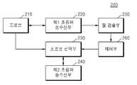
도 2는 본 발명의 일 실시예에 따른 초음파 진단 장치의 구성을 나타내는 블록도이다.2 is a block diagram showing the configuration of an ultrasound diagnosis apparatus according to an embodiment of the present invention.
도 2를 참조하면, 일 실시 예에 따른 초음파 진단 장치(100)는 프로브(20), 제1 초음파 송수신부(130), 제2 초음파 송수신부(115), 젤 검출부(135), 영상 처리부(150), 통신부(170), 메모리(180), 사용자 입력부(190), 및 제어부(195)를 포함할 수 있으며, 상술한 여러 구성들은 버스(185)를 통해 서로 연결될 수 있다.Referring to FIG. 2, the
프로브(20)는, 제1 초음파 송수신부(130) 및 제2 초음파 송수신부(115)로부터 인가된 구동 신호(driving signal)에 따라 대상체(10)로 초음파 신호를 송출하고, 대상체(10)로부터 반사된 에코 신호를 수신한다. 프로브(20)는 복수의 트랜스듀서 엘리먼트들을 포함하며, 복수의 엘리먼트들은 전달되는 전기적 신호에 따라 진동하며 음향 에너지인 초음파를 발생시킨다. 또한, 프로브(20)는 초음파 장치(100)의 본체와 유선 또는 무선으로 연결될 수 있으며, 초음파 장치(50)는 구현 형태에 따라 복수 개의 프로브(20)를 구비할 수 있다.The
제1 초음파 송수신부(130) 및 제2 초음파 송수신부(115)는 프로브(20)를 통하여, 초음파 신호를 송신하고, 반사된 에코 신호를 수신한다.The first
이때, 제1 초음파 송수신부(130)는 프로브의 젤 도포 여부를 검출하기 위하여, 초음파를 송수신할 수 있다. 제1 초음파 송수신부(130)는 프로브 정보에 기초하여, 송신할 초음파 신호의 송신 주파수 및 수신할 에코 신호의 수신 대역폭을 결정할 수 있으며, 결정된 값에 따라 초음파 신호를 송신하고, 에코 신호를 수신할 수 있다.In this case, the first
제1 초음파 송수신부(130)의 동작에 대해서는 이하, 도 6 내지 8을 참조하여, 자세히 설명하기로 한다.The operation of the first
젤 검출부(135)는 제1 초음파 송수신부에서 수신한 에코 신호에 기초하여, 프로브(20)에 젤이 도포되어 있는지 여부를 판단할 수 있다. 예를 들어, 젤 검출부(135)는 수신한 에코 신호가 기 설정된 젤 검출 임계값보다 큰 경우, 프로브(20)에 젤이 도포되어 있는 것으로 판단할 수 있다. 다만, 이에 한정하는 것은 아니다.The
이때, 젤 검출 임계값은 젤이 도포된 프로브를 통하여, 초음파 신호를 송신하고, 반사된 에코 신호에 기초하여 설정될 수 있다. 또한, 설정된 젤 검출 임계값은 메모리(180)에 저장될 수 있다.In this case, the gel detection threshold may be set based on a reflected echo signal by transmitting an ultrasonic signal through a probe on which the gel is applied. In addition, the set gel detection threshold may be stored in the
제2 초음파 송수신부(115)는 초음파 영상 획득을 위하여, 초음파를 송수신할 수 있으며, 제2 초음파 송수신부(115)는 송신부(110) 및 수신부(120)를 포함할 수 있다.The second ultrasonic transmitter/
송신부(110)는 프로브(20)에 구동 신호를 공급하며, 펄스 생성부(112), 송신 지연부(114), 및 펄서(116)를 포함한다. 펄스 생성부(112)는 소정의 펄스 반복 주파수(PRF, Pulse Repetition Frequency)에 따른 송신 초음파를 형성하기 위한 펄스(pulse)를 생성하며, 송신 지연부(114)는 송신 지향성(transmission directionality)을 결정하기 위한 지연 시간(delay time)을 펄스에 적용한다. 지연 시간이 적용된 각각의 펄스는, 프로브(20)에 포함된 복수의 진동자(vibrators)에 각각 대응된다. 펄서(116)는, 지연 시간이 적용된 각각의 펄스에 대응하는 타이밍(timing)으로, 프로브(20)에 구동 신호(또는, 구동 펄스(driving pulse))를 인가한다.The
수신부(120)는 프로브(20)로부터 수신되는 에코 신호를 처리하여 초음파 데이터를 생성하며, 증폭기(122), ADC(아날로그 디지털 컨버터, Analog Digital converter)(124), 수신 지연부(126), 및 합산부(128)를 포함할 수 있다. 증폭기(122)는 에코 신호를 각 채널(channel) 마다 증폭하며, ADC(124)는 증폭된 에코 신호를 아날로그-디지털 변환한다. 수신 지연부(126)는 수신 지향성(reception directionality)을 결정하기 위한 지연 시간을 디지털 변환된 에코 신호에 적용하고, 합산부(128)는 수신 지연부(126)에 의해 처리된 에코 신호를 합산함으로써 초음파 데이터를 생성한다.The receiving
영상 처리부(150)는 초음파 송수신부(115)에서 생성된 초음파 데이터에 대한 스캔 변환(scan conversion) 과정을 통해 초음파 영상을 생성하고 표시한다.The
한편, 초음파 영상은 A 모드(amplitude mode), B 모드(brightness mode) 및 M 모드(motion mode)에 따라 대상체를 스캔한 그레이 스케일(gray scale)의 초음파 영상뿐만 아니라, 대상체의 움직임을 도플러 영상으로 나타낼 수 있다. 도플러 영상은, 혈액의 흐름을 나타내는 혈류 도플러 영상 (또는, 컬러 도플러 영상으로도 불림), 조직의 움직임을 나타내는 티슈 도플러 영상, 및 대상체의 이동 속도를 파형으로 표시하는 스펙트럴 도플러 영상을 포함할 수 있다.On the other hand, the ultrasound image is a gray scale ultrasound image that scans the object according to the A mode, B mode, and M mode, as well as the movement of the object as a Doppler image. Can be indicated. The Doppler image may include a blood flow Doppler image indicating blood flow (or also referred to as a color Doppler image), a tissue Doppler image indicating tissue movement, and a spectral Doppler image indicating movement speed of an object as a waveform. have.
B 모드 처리부(141)는, 초음파 데이터로부터 B 모드 성분을 추출하여 처리한다. 영상 생성부(155)는, B 모드 처리부(141)에 의해 추출된 B 모드 성분에 기초하여 신호의 강도가 휘도(brightness)로 표현되는 초음파 영상을 생성할 수 있다.The B
마찬가지로, 도플러 처리부(142)는, 초음파 데이터로부터 도플러 성분을 추출하고, 영상 생성부(155)는 추출된 도플러 성분에 기초하여 대상체의 움직임을 컬러 또는 파형으로 표현하는 도플러 영상을 생성할 수 있다.Likewise, the
일 실시 예에 의한 영상 생성부(155)는, 대상체에 대한 2차원 초음파 영상을 생성할 수 있으며, 압력에 따른 대상체(10)의 변형 정도를 영상화한 탄성 영상 또한 생성할 수도 있다. 나아가, 영상 생성부(155)는 초음파 영상 상에 여러 가지 부가 정보를 텍스트, 그래픽으로 표현할 수도 있다. 한편, 생성된 초음파 영상은 메모리(180)에 저장될 수 있다.The
디스플레이부(160)는 생성된 초음파 영상을 표시 출력한다. 디스플레이부(160)는, 초음파 영상뿐 아니라 초음파 진단 장치(100)에서 처리되는 다양한 정보를 GUI(Graphic User Interface)를 통해 화면 상에 표시 출력할 수 있다. 한편, 초음파 진단 장치(100)는 구현 형태에 따라 둘 이상의 디스플레이부(160)를 포함할 수 있다.The
디스플레이부(160)는 액정 디스플레이(liquid crystal display), 박막 트랜지스터 액정 디스플레이(thin film transistor-liquid crystal display), 유기 발광 다이오드(organic light-emitting diode), 플렉시블 디스플레이(flexible display), 3차원 디스플레이(3D display), 전기영동 디스플레이(electrophoretic display) 중에서 적어도 하나를 포함할 수 있다.The
또한, 디스플레이부(160)와 사용자 입력부가 레이어 구조를 이루어 터치 스크린으로 구성되는 경우, 디스플레이부(160)는 출력 장치 이외에 사용자의 터치에 의한 정보의 입력이 가능한 입력 장치로도 사용될 수 있다.In addition, when the
터치 스크린은 터치 입력 위치, 터치된 면적뿐만 아니라 터치 압력까지도 검출할 수 있도록 구성될 수 있다. 또한, 터치 스크린은 직접 터치(real-touch)뿐만 아니라 근접 터치(proximity touch)도 검출될 수 있도록 구성될 수 있다.The touch screen may be configured to detect not only a touch input position and a touched area, but also a touch pressure. In addition, the touch screen may be configured to detect not only a real-touch but also a proximity touch.
본 명세서에서 “직접 터치(real-touch)”라 함은 화면에 실제로 포인터(pointer)가 터치된 경우를 말하고, “근접 터치(proximity-touch)”라 함은 포인터(pointer)가 화면에 실제로 터치는 되지 않고, 화면으로부터 소정 거리 떨어져 접근된 경우를 말한다. 본 명세서에서는 포인터(pointer)는 디스플레이된 화면의 특정 부분을 터치하거나 근접 터치하기 위한 터치 도구를 말한다. 그 일예로, 전자 펜, 손가락 등이 있다.In this specification, “real-touch” refers to a case where a pointer is actually touched on the screen, and “proximity-touch” refers to a pointer actually touching the screen. It does not work and is approached a predetermined distance away from the screen. In this specification, a pointer refers to a touch tool for touching a specific part of a displayed screen or touching a specific part of the displayed screen. For example, there are electronic pens and fingers.
도면에는 도시되지 않았지만, 초음파 진단 장치(100)는, 터치 스크린에 대한 직접 터치 또는 근접 터치를 감지하기 위해 터치스크린의 내부 또는 근처에 다양한 센서를 구비할 수 있다. 터치스크린의 터치를 감지하기 위한 센서의 일례로 촉각 센서가 있다.Although not shown in the drawings, the
촉각 센서는 사람이 느끼는 정도로 또는 그 이상으로 특정 물체의 접촉을 감지하는 센서를 말한다. 촉각 센서는 접촉면의 거칠기, 접촉 물체의 단단함, 접촉 지점의 온도 등의 다양한 정보를 감지할 수 있다.The tactile sensor refers to a sensor that detects contact with a specific object to the extent that a person feels it or more. The tactile sensor can detect various information such as roughness of a contact surface, hardness of a contact object, and temperature of a contact point.
또한, 터치스크린의 터치를 감지하기 위한 센서의 일례로 근접 센서가 있다. 근접 센서는 소정의 검출면에 접근하는 물체, 혹은 근방에 존재하는 물체의 유무를 전자계의 힘 또는 적외선을 이용하여 기계적 접촉이 없이 검출하는 센서를 말한다.In addition, as an example of a sensor for sensing a touch of a touch screen, there is a proximity sensor. The proximity sensor refers to a sensor that detects the presence or absence of an object approaching a predetermined detection surface or an object existing in the vicinity using the force of an electromagnetic field or infrared rays without mechanical contact.
근접 센서의 예로는 투과형 광전 센서, 직접 반사형 광전 센서, 미러 반사형 광전 센서, 고주파 발진형 근접 센서, 정전용량형 근접 센서, 자기형 근접 센서, 적외선 근접 센서 등이 있다.Examples of the proximity sensor include a transmission type photoelectric sensor, a diffuse reflection type photoelectric sensor, a mirror reflection type photoelectric sensor, a high frequency oscillation type proximity sensor, a capacitive type proximity sensor, a magnetic type proximity sensor, an infrared proximity sensor, and the like.
통신부(170)는, 유선 또는 무선으로 네트워크(30)와 연결되어 외부 디바이스나 서버와 통신한다. 통신부(170)는 의료 영상 정보 시스템(PACS, Picture Archiving and Communication System)을 통해 연결된 병원 서버나 병원 내의 다른 의료 장치와 데이터를 주고 받을 수 있다. 또한, 통신부(170)는 의료용 디지털 영상 및 통신(DICOM, Digital Imaging and Communications in Medicine) 표준에 따라 데이터 통신할 수 있다.The
통신부(170)는 네트워크(30)를 통해 대상체의 초음파 영상, 초음파 데이터, 도플러 데이터 등 대상체의 진단과 관련된 데이터를 송수신할 수 있으며, CT, MRI, X-ray 등 다른 의료 장치에서 촬영한 의료 영상 또한 송수신할 수 있다. 나아가, 통신부(170)는 서버로부터 환자의 진단 이력이나 치료 일정 등에 관한 정보를 수신하여 대상체의 진단에 활용할 수도 있다. 나아가, 통신부(170)는 병원 내의 서버나 의료 장치뿐만 아니라, 의사나 환자의 휴대용 단말과 데이터 통신을 수행할 수도 있다.The
통신부(170)는 유선 또는 무선으로 네트워크(30)와 연결되어 서버(32), 의료 장치(34), 또는 휴대용 단말(36)과 데이터를 주고 받을 수 있다. 통신부(170)는 외부 디바이스와 통신을 가능하게 하는 하나 이상의 구성 요소를 포함할 수 있으며, 예를 들어 근거리 통신 모듈(171), 유선 통신 모듈(172), 및 이동 통신 모듈(173)을 포함할 수 있다.The
근거리 통신 모듈(171)은 소정 거리 이내의 근거리 통신을 위한 모듈을 의미한다. 본 발명의 일 실시 예에 따른 근거리 통신 기술에는 무선 랜(Wireless LAN), 와이파이(Wi-Fi), 블루투스, 지그비(zigbee), WFD(Wi-Fi Direct), UWB(ultra wideband), 적외선 통신(IrDA, infrared Data Association), BLE (Bluetooth Low Energy), NFC(Near Field Communication) 등이 있을 수 있으나, 이에 한정되는 것은 아니다.The short-
유선 통신 모듈(172)은 전기적 신호 또는 광 신호를 이용한 통신을 위한 모듈을 의미하며, 일 실시 예에 의한 유선 통신 기술에는 페어 케이블(pair cable), 동축 케이블, 광섬유 케이블, 이더넷(ethernet) 케이블 등이 포함될 수 있다.The
이동 통신 모듈(173)은, 이동 통신망 상에서 기지국, 외부의 단말, 서버 중 적어도 하나와 무선 신호를 송수신한다. 여기에서, 무선 신호는, 음성 호 신호, 화상 통화 호 신호 또는 문자/멀티미디어 메시지 송수신에 따른 다양한 형태의 데이터를 포함할 수 있다.The
메모리(180)는 초음파 진단 장치(100)에서 처리되는 여러 가지 정보를 저장한다. 예를 들어, 메모리(180)는 입/출력되는 초음파 데이터, 초음파 영상 등 대상체의 진단에 관련된 의료 데이터를 저장할 수 있고, 초음파 진단 장치(100) 내에서 수행되는 알고리즘이나 프로그램을 저장할 수도 있다.The
본 발명의 일 실시 예와 관련하여, 메모리(180)는 대상체의 단면 정보에 대응하는 단면 정보 영상을 미리 맵핑하여 저장할 수 있다. 예를 들어, 제1 단면 정보에 대응하는 제1 단면 정보 영상, 제2 단면 정보에 대응하는 제2 단면 정보 영상을 저장할 수 있다. 단면 정보는 대상체의 단면을 식별할 수 있는 다양한 데이터를 포함할 수 있다. 예를 들어, 대상체의 제1 단면에 대한 초음파 영상에만 포함되는 객체의 형상이나 길이, 넓이에 대한 데이터, 제1 단면 영상에서만 나타나는 특정 범위의 밝기 값 등이 제1 단면 정보에 포함될 수 있다.In connection with an embodiment of the present invention, the
메모리(180)는 플래시 메모리, 하드디스크, EEPROM 등 여러 가지 종류의 저장매체로 구현될 수 있다. 또한, 초음파 진단 장치(100)는 웹 상에서 메모리(180)의 저장 기능을 수행하는 웹 스토리지(web storage) 또는 클라우드 서버를 운영할 수도 있다.The
사용자 입력부(190)는, 사용자가 초음파 진단 장치(50)의 동작 제어를 위하여 입력하는 입력 데이터를 발생시킨다. 사용자 입력부(190)는 키 패드, 마우스, 터치 패드, 트랙볼, 조그 스위치 등 하드웨어 구성을 포함할 수 있으나 이에 한정되는 것은 아니며, 심전도 측정 모듈, 호흡 측정 모듈, 음성 인식 센서, 제스쳐 인식 센서, 지문 인식 센서, 홍채 인식 센서, 깊이 센서, 거리 센서 등의 다양한 구성을 더 포함할 수 있다.The
본 발명의 일 실시 예와 관련하여, 사용자 입력부(190)는 제1 초음파 영상 및 제2 초음파 영상 중 어느 하나를 선택하는 사용자 입력을 수신하거나, 단면 정보 영상에 포함된 복수의 단면 중 어느 하나를 선택하는 사용자 입력을 수신할 수 있다.In connection with an embodiment of the present invention, the
특히, 터치 패드가 전술한 디스플레이부(160)와 상호 레이어 구조를 이루는 터치 스크린도 포함할 수 있다.In particular, the touch pad may also include a touch screen that forms a layer structure with the
이때, 본 발명의 일 실시 예에 따른 초음파 진단 장치(100)는, 소정 모드의 초음파 영상 및 초음파 영상에 대한 컨트롤 패널을 터치 스크린상에 표시할 수 있다. 그리고 초음파 진단 장치(100)는, 터치 스크린을 통해 초음파 영상에 대한 사용자의 터치 제스처를 감지할 수 있다.In this case, the
본 발명의 일 실시 예에 따른 초음파 진단 장치(100)는, 일반적인 초음파 장치의 컨트롤 패널에 포함되어 있던 버튼들 중 사용자가 자주 사용하는 일부 버튼을 물리적으로 구비하고, 나머지 버튼들은 GUI(Graphical User Interface) 형태로 터치 스크린을 통해 제공할 수 있다.The
제어부(195)는 초음파 진단 장치(100)의 동작을 전반적으로 제어한다. 즉, 제어부(195)는 도 2에 도시된 프로브(20), 초음파 송수신부(100), 영상 처리부(150), 통신부(170), 메모리(180), 및 사용자 입력부(190) 간의 동작을 제어할 수 있다.The
프로브(20), 초음파 송수신부(115), 영상 처리부(150), 통신부(170), 메모리(180), 사용자 입력부(190) 및 제어부(195) 중 일부 또는 전부는 소프트웨어 모듈에 의해 동작할 수 있으나 이에 제한되지 않으며, 상술한 구성 중 일부가 하드웨어에 의해 동작할 수도 있다. 또한, 초음파 송수신부(115), 영상 처리부(150), 및 통신부(170) 중 적어도 일부는 제어부(195)에 포함될 수 있으나, 이러한 구현 형태에 제한되지는 않는다.Some or all of the
도 3은 본 발명의 일 실시 예에 따른 초음파 진단 장치(200)의 구성을 나타내는 블록도이고, 도 4는 도 3의 프로브 선택부(230)를 설명하기 위한 도면이고, 도 5는 도 3의 제1 초음파 송수신부(220)를 설명하기 위한 도면이다.3 is a block diagram showing the configuration of an
도 3을 참조하면, 초음파 진단 장치(200)는 프로브(210), 프로브 선택부(230), 제1 초음파 송수신부(220), 제2 초음파 송수신부(240), 젤 검출부(250) 및 제어부(260)를 포함할 수 있다. 3, the
도 3의 프로브(210)는 도 2의 프로브(20)에 대응되는 구성으로, 복수의 트랜스듀서 엘리먼트들을 포함할 수 있다. 각각의 트랜스듀서 엘리먼트들은 제1 초음파 송수신부(220) 또는 제2 초음파 송수신부(240)로부터 인가된 구동 신호에 따라 대상체로 초음파 신호를 송출하고, 대상체로부터 반사된 에코 신호를 수신할 수 있다.The
프로브 선택부(230)는 프로브 포트에 연결된 복수의 프로브 중 적어도 하나를 활성화시킬 수 있다. 활성화된 프로브는 초음파 영상 획득을 위하여, 제2 초음파 송수신부(240)로부터 인가된 구동 신호에 따라 대상체로 초음파 신호를 송출하고, 대상체로부터 반사된 에코 신호를 수신할 수 있다.The
예를 들어, 도 3의 제2 초음파 송수신부(240)는 빔포머를 포함할 수 있으며, 복수의 프로브 중 프로브 선택부(230)에 의해 활성화된 프로브는 빔포머와 전기적으로 연결될 수 있다. 이때, 빔포머는 도 2에서 설명한 송신부(110)및 수신부(120)를 포함할 수 있다.For example, the second
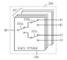
도 4를 참조하면, 프로브 선택부(230)는 빔포머와 프로브 포트를 연결하는 복수의 프로브 선택 회로를 포함할 수 있다. 예를 들어, 프로브가 128개의 트랜스듀서 엘리먼트를 포함하고, 제2 초음파 송수신부(240)가 128개의 빔포밍 회로를 포함하여, 128 채널을 형성하는 경우, 프로브 선택부(230)는 128개의 프로브 선택 회로(231, 제1 내지 제128 프로브 선택 회로)들을 포함할 수 있다.Referring to FIG. 4, the
이하에서는, 설명의 편의를 위해, 128개의 프로브 선택 회로(231, 제1 내지 제128 프로브 선택 회로) 중 하나의 프로브 선택 회로인 제1 프로브 선택 회로(235)를 기준으로 설명하기로 한다. 따라서, 제1 프로브 선택 회로(235)에 대한 설명은 나머지 제2 프로브 선택 회로 내지 제128 프로브 선택 회로에도 동일하게 적용될 수 있다.Hereinafter, for convenience of description, a description will be made based on the first
제1 프로브 선택 회로(235)는 도 4에 도시된 바와 같이, 기계식 또는 전자식의 스위치(이하, 스위치)를 포함할 수 있으며, 예를 들어, 프로브 포트가 4개로 구성된 경우, 제1 프로브 선택 회로(235)는 3개의 스위치(235a, 235b, 235c)를 포함할 수 있다. 다만 이에 한정되는 것은 아니다.As shown in FIG. 4, the first
프로브 포트(A)의 제1 채널을 빔포머(BF)와 연결하는 경우, 제1 프로브 선택 회로는 2개의 스위치(235a, 235b)를 이용하여, 제1 채널에 대응하는 프로브 포트(A1)와 빔포머(BF1)를 전기적으로 연결할 수 있다. 나머지 제2 내지 제128 프로브 선택 회로도 제1 프로브 선택 회로와 마찬가지로 제2 채널 내지 제128 채널에 대응하는 프로브 포트(A2 내지 A128)와 빔포머(BF2 내지 BF128)를 전기적으로 연결할 수 있다.When connecting the first channel of the probe port (A) with the beamformer (BF), the first probe selection circuit uses two switches (235a, 235b), and the probe port (A1) corresponding to the first channel and The beam former (BF1) can be electrically connected. Like the first probe selection circuit, the remaining second to 128th probe selection circuits may electrically connect the probe ports A2 to A128 corresponding to the second to 128th channels and the beamformers BF2 to BF128.
이에 따라, 제2 초음파 송수신부(240) 활성화된 프로브를 수신한 에코 신호를 처리할 수 있다.Accordingly, the second
제1 초음파 송수신부(220)는 프로브 포트에 연결된 프로브의 젤 도포 여부를 검출하기 위하여, 프로브로 구동신호를 인가하고, 에코 신호를 수신할 수 있다. 예를 들어, 도 5를 참조하면, 제1 초음파 송수신부(220)는 복수의 프로브 포트와 연결되는 회로를 포함할 수 있으며, 제1 초음파 송수신부(220)는 복수의 스위치를 이용하여, 복수의 프로브에 포함된 특정 엘리먼트(도 5에서는, 32 엘리먼트 및 96 엘리먼트)에 대응하는 프로브 포트와 펄스 송신기(Tx1, Tx2) 또는 수신기(Rx1, Rx2)를 전기적으로 연결할 수 있다. 여기서, 특정 엘리먼트의 선택은 프로브별로 또는 기능 향상을 위해 변경될 수 있다.The first
또한, 제1 초음파 송수신부(220)는 펄스 생성부(223)를 포함하고, 펄스 생성부(223)는 프로브 정보에 기초하여, 프로브에서 물리적으로 송신 가능한 대역의 주파수를 가지는 펄스를 생성하고, 생성된 펄스를 펄스 송신기(Tx1, Tx2)로 송신할 수 있다.In addition, the first
또한, 제1 초음파 송수신부(220)는 밴드 패스 필터(BPF)를 포함하여, 수신기(Rx1, Rx2)에서 수신한 신호 중 송신한 대역의 주파수가 통과할 수 있는 대역폭을 가지는 신호를 ADC로 입력할 수 있다.In addition, the first
처리된 에코 신호는 젤 검출부(250)로 입력될 수 있으며, 젤 검출부(250)는 입력된 에코 신호값에 기초하여, 프로브에 젤이 도포되어 있는지 여부를 판단할 수 있다.The processed echo signal may be input to the
젤 검출부(250)는 기 설정된 젤 검출 임계값과 수신한 에코 신호값을 비교하여, 에코 신호값이 기 설정된 임계값보다 큰 경우, 프로브에 젤이 도포되어 있는 것으로 판단할 수 있다. 이때, 젤 검출 임계값 설정에 대해서는 이하, 도 6 및 7을 참조하여 자세히 설명하기로 한다.The
한편, 프로브에 젤이 도포되어 있는 것으로 판단되는 경우, 제어부(260)는 젤이 도포된 프로브를 활성화시키도록 제어할 수 있다. 예를 들어, 프로브 선택부(230)로 프로브 변경 명령을 전송하여, 현재 활성화되어 있는 프로브를 비활성화시키고, 젤이 도포되어 있는 프로브를 활성화시키도록 제어할 수 있다.Meanwhile, when it is determined that the gel is applied to the probe, the
한편, 도 2 및 3에서 도시된 초음파 진단 장치(100, 200)의 블록도는 본 발명의 일 실시 예를 위한 블록도이다. 블록도의 각 구성요소는 실제 구현되는 초음파 진단 장치의 사양에 따라 통합, 추가, 또는 생략될 수 있다. 즉, 필요에 따라 2 이상의 구성요소가 하나의 구성요소로 합쳐지거나, 혹은 하나의 구성요소가 2 이상의 구성요소로 세분되어 구성될 수 있다. 또한, 각 블록에서 수행하는 기능은 본 발명의 실시 예를 설명하기 위한 것이며, 그 구체적인 동작이나 장치는 본 발명의 권리범위를 제한하지 아니한다.Meanwhile, the block diagrams of the
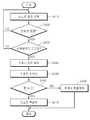
도 6은 본 발명의 일 실시 예에 따른 초음파 진단 장치의 동작방법을 나타내는 흐름도이고, 도 7은 도 6의 동작방법을 설명하기 위해 참조되는 도면이다.6 is a flowchart illustrating a method of operating an ultrasound diagnosis apparatus according to an exemplary embodiment of the present invention, and FIG. 7 is a diagram referenced to explain the operation method of FIG. 6.
도 6을 참조하면, 초음파 진단 장치(100, 200)는 프로브 포트를 선택하고(S310), 선택된 프로브 포트에 프로브가 연결되어 있는지를 판단할 수 있다(S320). 예를 들어, 도 1에 도시된 바와 같이, 초음파 진단 장치(100)가 4개의 프로브 포트를 포함하는 경우, 제1 내지 제4 프로브 포트(A, B, C, D)들에 프로브가 연결되어 있는지를 판단할 수 있다.Referring to FIG. 6, the
판단결과, 프로브 포트에 프로브가 연결된 경우, 초음파 진단 장치는 연결된 프로브의 정보를 획득할 수 있다(S330).As a result of the determination, when the probe is connected to the probe port, the ultrasound diagnosis apparatus may obtain information on the connected probe (S330).
예를 들어, 프로브 포트에 연결된 프로브의 ID를 인식하여, 기 저장된 프로브 ID와 비교하고, 대응되는 프로브 정보를 획득할 수 있다.For example, an ID of a probe connected to a probe port may be recognized, compared with a previously stored probe ID, and corresponding probe information may be obtained.
또한, 초음파 진단 장치(100, 200)는 획득한 프로브 정보에 기초하여, 젤이 도포된 프로브를 통하여, 초음파 신호를 송신하고, 에코 신호를 수신할 수 있다(S340).Also, the
이때, 초음파 진단 장치(100, 200)는 프로브 정보에 기초하여, 프로브에서 물리적으로 송신 가능한 송신 주파수를 가지는 초음파 신호를 송신하고, 이에 대응하는 수신 대역폭을 가지는 에코 신호를 수신할 수 있다. 또한, 초음파 진단 장치(100, 200)는 프로브에 포함된 적어도 하나의 엘리먼트를 통하여, 초음파 신호를 송신하고, 에코 신호를 수신할 수 있다. 이때, 초음파 진단 장치(100, 200)는 프로브에 포함된 제1 엘리먼트 및 제2 엘리먼트를 통하여, 초음파 신호를 송신하고 에코 신호를 수신할 수 있다.In this case, the
예를 들어, 도 7을 참조하면, 128개의 엘리먼트를 가지는 프로브인 경우, 제1 엘리먼트는 32번째 엘리먼트(el32)일 수 있으며, 제2 엘리먼트는 96번째 엘리먼트(el96)일 수 있다. 다만, 이에 한정하지 않으며, 다양한 방법으로 다양한 수의 엘리먼트를 선택할 수 있다.For example, referring to FIG. 7, in the case of a probe having 128 elements, a first element may be a 32nd element el32, and a second element may be a 96th element el96. However, the present invention is not limited thereto, and various numbers of elements may be selected in various ways.
초음파 진단 장치(100, 200)는 도 7의 (a)에 도시된 바와 같이, 제1 엘리먼트(el32)를 통하여, 초음파 신호를 송신하고, 제1 엘리먼트(el32)를 통하여, 에코 신호를 수신할 수 있다(제1 모드).The
또한, 도 7의 (b)에 도시된 바와 같이, 제2 엘리먼트(el96)를 통하여, 초음파 신호를 송신하고, 제2 엘리먼트(el96)를 통하여, 에코 신호를 수신할 수 있다(제2 모드).In addition, as shown in (b) of FIG. 7, an ultrasonic signal may be transmitted through the second element el96 and an echo signal may be received through the second element el96 (second mode). .
또한, 도 7의 (c)에 도시된 바와 같이, 제1 엘리먼트(el32)를 통하여, 초음파 신호를 송신하고, 제2 엘리먼트(el96)를 통하여, 에코 신호를 수신할 수 있다(제3 모드).In addition, as shown in (c) of FIG. 7, an ultrasonic signal may be transmitted through the first element el32 and an echo signal may be received through the second element el96 (third mode). .
또한, 도 7의 (d)에 도시된 바와 같이, 제2 엘리머트(el96)를 통하여, 초음파 신호를 송신하고, 제1 엘리먼트(el32)를 통하여, 에코 신호를 수신할 수 있다(제4 모드).In addition, as shown in (d) of FIG. 7, an ultrasonic signal may be transmitted through the second element el96 and an echo signal may be received through the first element el32 (4th mode ).
다만, 제1 초음파 송수신부(220)의 동작은 상술한 동작 모드들에 한정되는 것은 아니며, 초음파 신호를 송신하고, 에코 신호를 수신하는 엘리먼트의 수에 따라 다양한 동작 모드로 초음파 신호를 송신하고, 에코 신호를 수신할 수 있다.However, the operation of the first
한편, 제1 초음파 송수신부(220)는 수신한 에코 신호에 기초하여, 젤 검출 임계값을 설정할 수 있다(S350).Meanwhile, the first
예를 들어, 제1 초음파 송수신부(220)가 도 7에서 설명한 4가지 모드로 동작하여, 에코 신호를 수신한 경우, 제1 모드 내지 제4 모드 각각에서 수신한 에코 신호에 기초하여, 제1 임계값 내지 제4 임계값을 설정할 수 있다. 또한, 설정된 젤 검출 임계값은 메모리(180)에 저장될 수 있다.For example, when the first
한편, 다른 프로브 포트에 연결된 프로브에 대해서도 330 단계(S330) 내지 350 단계(S350)들을 수행하여, 젤 검출 임계값을 설정할 수 있다.Meanwhile, steps 330 (S330) to 350 (S350) may be performed for a probe connected to another probe port to set a gel detection threshold.
또한, 초음파 진단 장치(100, 200)는 전원이 인가되면, 도 6의 310 단계(S310) 부터 350 단계(S350)를 수행하며, 이후, 프로브 포트에 새로운 프로브가 연결되는 것을 모니터링하여, 연결되는 프로브가 변경될 때마다 도 6의 310 단계(S310) 부터 350 단계(S350)를 수행할 수 있다.In addition, when power is applied, the
도 8은 본 발명의 일 실시 예에 따른 초음파 진단 장치의 동작방법을 나타내는 흐름도이다.8 is a flowchart illustrating a method of operating an ultrasound diagnosis apparatus according to an embodiment of the present invention.
도 8을 참조하면, 초음파 진단 장치(100, 200)는 복수의 프로브 포트 중 어느 하나를 선택하여(S410), 선택된 프로브 포트에 프로브가 연결되어 있는지 여부를 판단할 수 있다(S420).Referring to FIG. 8, the
이때, 프로브가 연결되어 있지 않은 경우, 초음파 진단 장치(100, 200)는 다른 포트를 선택하여, 선택된 프로브 포트에 프로브가 연결되어 있는지 여부를 판단할 수 있다.In this case, when the probe is not connected, the
반면에, 프로브가 연결된 경우, 초음파 진단 장치(100, 200)는 연결된 프로브가 비활성화된 프로브인지를 판단할 수 있다(S430). 예를 들어, 초음파 진단 장치(100, 200)는 프로브가 연결된 프로브 포트와 제2 초음파 송수신부와의 연결상태를 확인하여, 프로브 포트에 연결된 프로브가 비활성화된 프로브인지를 판단할 수 있다.On the other hand, when the probe is connected, the
활성화된 프로브인 경우, 초음파 진단 장치(100, 200)는 다른 프로브 포트를 선택하여, 420 단계(S420) 및 430 단계(S430)를 수행할 수 있다.In the case of an activated probe, the
반면에, 프로브 포트에 연결된 프로브가 비활성화된 프로브인 경우, 초음파 진단 장치(100, 200)는 비활성화된 프로브의 정보를 획득할 수 있다(S440).On the other hand, when the probe connected to the probe port is a deactivated probe, the
예를 들어, 프로브 포트에 연결된 프로브의 ID를 인식하여, 기 저장된 프로브 ID와 비교하고, 대응되는 프로브 정보를 획득할 수 있다.For example, an ID of a probe connected to a probe port may be recognized, compared with a previously stored probe ID, and corresponding probe information may be obtained.
또한, 초음파 진단 장치(100, 200)는 획득한 프로브 정보에 기초하여, 비활성화된 프로브를 통하여, 초음파 신호를 송신하고, 에코 신호를 수신할 수 있다(S450).Also, the
이때, 초음파 진단 장치(100, 200)는 프로브 정보에 기초하여, 프로브에서 물리적으로 송신 가능한 송신 주파수를 가지는 초음파 신호를 송신하고, 이에 대응하는 수신 대역폭을 가지는 에코 신호를 수신할 수 있다.In this case, the
또한, 초음파 진단 장치(100, 200)는 프로브에 포함된 적어도 하나의 엘리먼트를 통하여, 초음파 신호를 송신하고, 에코 신호를 수신할 수 있다. 이때, 초음파 진단 장치(100, 200)는 프로브에 포함된 제1 엘리먼트 및 제2 엘리먼트를 통하여, 초음파 신호를 송신하고 에코 신호를 수신할 수 있으며, 예를 들어, 도 7에서 설명한 바와 같이, 4가지 동작모드로 초음파 신호를 송신하고, 에코 신호를 수신할 수 있다.Also, the
이에 따라, 초음파 진단 장치(100, 200)는 제1 모드에서 제1 에코 신호, 제2 모드에서 제2 에코 신호, 제3 모드에서 제3 에코 신호, 제4 모드에서 제4 에코 신호를 수신하고, 제1 부터 제4 까지의 에코 신호 값을 획득할 수 있다.Accordingly, the
또한, 초음파 진단 장치(100, 200)는 도 6에서 설명한 동작방법에 따라 기 설정된 젤 검출 임계값을 상기 450 단계(S450)에서 획득한 에코 신호값과 비교하여, 비활성화된 프로브에 젤이 도포되어 있는지 여부를 판단할 수 있다(S460).In addition, the
예를 들어, 초음파 진단 장치(100, 200)는 에코 신호값이 젤 검출 임계값보다 큰 경우, 프로브에 젤이 도포되어 있는 것으로 판단할 수 있다. 또한, 제1 내지 제4 에코 신호값 각각을 제1 내지 제4 임계값 각각과 비교하여, 그 비교결과에 따라 프로브에 젤이 도포되어 있는지 여부를 판단할 수도 있다.For example, when the echo signal value is greater than the gel detection threshold value, the
이에 따라, 프로브에 젤이 도포되어 있는 것으로 판단되는 경우, 초음파 진단 장치(100, 200)는 프로브를 활성화시키도록 제어할 수 있다(S470).Accordingly, when it is determined that the gel is applied to the probe, the
예를 들어, 프로브 선택부(230)로 프로브 변경 명령을 전송하여, 현재 활성화되어 있는 프로브를 비활성화시키고, 젤이 도포되어 있는 프로브를 활성화시키도록 제어할 수 있다.For example, by transmitting a probe change command to the
반면에, 프로브에 젤이 도포되어 있지 않은 것으로 판단되는 경우, 초음파 진단 장치(100, 200)는 프로브의 비활성 상태를 유지하도록 제어할 수 있다(S480).On the other hand, when it is determined that the gel is not applied to the probe, the
한편, 본 발명의 초음파 진단 장치 및 그 동작방법은 컴퓨터로 읽을 수 있는 기록매체에 컴퓨터가 읽을 수 있는 코드로서 구현하는 것이 가능하다. 컴퓨터가 읽을 수 있는 기록매체는 컴퓨터 시스템에 의하여 읽혀질 수 있는 데이터가 저장되는 모든 종류의 기록장치를 포함한다. 컴퓨터가 읽을 수 있는 기록매체의 예로는 ROM, RAM. CD-ROM, 자기 테이프, 플로피디스크, 광 데이터 저장장치 등이 있다. 또한, 컴퓨터가 읽을 수 있는 기록매체는 네트워크로 연결된 컴퓨터 시스템에 분산되어, 분산방식으로 프로세서가 읽을 수 있는 코드가 저장되고 실행될 수 있다.Meanwhile, the ultrasound diagnosis apparatus and its operation method of the present invention can be implemented as computer-readable codes on a computer-readable recording medium. The computer-readable recording medium includes all types of recording devices that store data that can be read by a computer system. Examples of computer-readable recording media include ROM and RAM. There are CD-ROMs, magnetic tapes, floppy disks, and optical data storage devices. In addition, the computer-readable recording medium is distributed over a computer system connected through a network, so that code that can be read by the processor can be stored and executed in a distributed manner.
또한, 이상에서는 본 발명의 실시예에 대하여 도시하고 설명하였지만, 본 발명은 상술한 특정의 실시 예에 한정되지 아니하며, 청구범위에서 청구하는 본 발명의 요지를 벗어남이 없이 당해 발명이 속하는 기술분야에서 통상의 지식을 가진 자에 의해 다양한 변형실시가 가능한 것은 물론이고, 이러한 변형실시들은 본 발명의 기술적 사상이나 전망으로부터 개별적으로 이해되어져서는 안될 것이다.In addition, although the embodiments of the present invention have been illustrated and described above, the present invention is not limited to the specific embodiments described above, and in the technical field to which the present invention pertains without departing from the gist of the present invention claimed in the claims. Various modifications may be possible by those of ordinary skill in the art, and these modifications should not be understood individually from the technical spirit or prospect of the present invention.
Claims (17)
Translated fromKorean상기 수신한 제1 에코 신호에 기초하여, 상기 비활성화된 프로브에 젤이 도포되어 있는지 여부를 판단하는 젤 검출부; 및
상기 프로브에 젤이 도포된 것으로 판단되면, 상기 비활성화된 프로브를 활성화시키도록 제어하는 제어부를 포함하고,
상기 비활성화된 프로브는, 적어도 하나의 엘리먼트를 포함하고,
상기 초음파 송수신부는, 상기 적어도 하나의 엘리먼트를 통하여, 상기 초음파 신호를 송신하고, 상기 제1 에코 신호를 수신하는 것을 특징으로 하는 초음파 진단 장치.An ultrasonic transceiving unit configured to transmit an ultrasonic signal and receive a reflected first echo signal through an inactivated probe among the plurality of probes;
A gel detection unit determining whether gel is applied to the deactivated probe based on the received first echo signal; And
When it is determined that the gel is applied to the probe, it includes a control unit for controlling to activate the inactivated probe,
The deactivated probe includes at least one element,
The ultrasonic transceiving unit, through the at least one element, transmits the ultrasonic signal and receives the first echo signal.
상기 제어부는
상기 비활성화된 프로브 정보를 획득하고,
상기 초음파 송수신부는,
상기 획득된 프로브 정보에 기초하여, 상기 초음파 신호의 송신 주파수 및 상기 제1 에코 신호의 수신 대역폭을 결정하고, 결정된 값에 따라 상기 초음파 신호를 송신하고, 상기 제1 에코 신호를 수신하는 것을 특징으로 하는 초음파 진단 장치.The method of claim 1,
The control unit
Obtaining the deactivated probe information,
The ultrasonic transceiving unit,
Based on the acquired probe information, determining a transmission frequency of the ultrasound signal and a reception bandwidth of the first echo signal, transmitting the ultrasound signal according to the determined value, and receiving the first echo signal Ultrasound diagnostic device.
상기 비활성화된 프로브는 제1 엘리먼트 및 제2 엘리먼트를 포함하고,
상기 초음파 송수신부는,
상기 제1 엘리먼트를 통하여, 상기 초음파 신호를 송신하고, 상기 제1 에코 신호를 수신하는 제1 모드, 상기 제2 엘리먼트를 통하여, 상기 초음파 신호를 송신하고, 상기 제1 에코 신호를 수신하는 제2 모드, 상기 제1 엘리먼트를 통하여, 상기 초음파 신호를 송신하고, 상기 제2 엘리먼트를 통하여, 상기 제1 에코 신호를 수신하는 제3 모드 및 상기 제2 엘리먼트를 통하여, 상기 초음파 신호를 송신하고, 상기 제1 엘리먼트를 통하여, 상기 제1 에코 신호를 수신하는 제4 모드 중 적어도 하나의 모드로 동작하는 것을 특징으로 하는 초음파 진단 장치.The method of claim 1,
The deactivated probe includes a first element and a second element,
The ultrasonic transceiving unit,
A first mode for transmitting the ultrasonic signal through the first element and receiving the first echo signal, and a second mode for transmitting the ultrasonic signal through the second element and receiving the first echo signal Mode, a third mode for transmitting the ultrasonic signal through the first element and receiving the first echo signal through the second element and transmitting the ultrasonic signal through the second element, The ultrasound diagnosis apparatus, characterized in that operating in at least one of the fourth modes for receiving the first echo signal through the first element.
상기 초음파 송수신부는,
상기 복수의 프로브 정보에 기초하여, 젤이 도포된 상기 복수의 프로브로 초음파 신호를 송신하고, 제2 에코 신호를 수신하며,
상기 제어부는,
상기 제2 에코 신호를 기초로, 젤 검출 임계값을 설정하고,
상기 젤 검출부는,
상기 제1 에코 신호 값과 상기 젤 검출 임계값을 비교하여, 상기 비활성화된 프로브에 젤이 도포되어 있는지 여부를 판단하는 것을 특징으로 하는 초음파 진단 장치.The method of claim 1,
The ultrasonic transceiving unit,
Based on the information of the plurality of probes, an ultrasonic signal is transmitted to the plurality of probes on which the gel is applied, and a second echo signal is received,
The control unit,
Based on the second echo signal, a gel detection threshold is set,
The gel detection unit,
And comparing the first echo signal value with the gel detection threshold to determine whether or not gel is applied to the deactivated probe.
상기 젤 검출부는
상기 제1 에코 신호 값이 상기 젤 검출 임계값보다 큰 경우, 상기 프로브에 젤이 도포된 것으로 판단하는 것을 특징으로 하는 초음파 진단 장치.The method of claim 5,
The gel detection unit
When the first echo signal value is greater than the gel detection threshold, it is determined that the gel is applied to the probe.
상기 장치는,
상기 복수의 프로브 중 활성화된 프로브로부터 초음파 신호를 수신하여, 빔포밍을 수행하는 빔포머; 및
상기 복수의 프로브 중 적어도 하나의 프로브를 상기 빔포머와 전기적으로 차단시켜, 비활성화시키거나, 상기 적어도 하나의 프로브를 상기 빔포머와 전기적으로 연결시켜, 활성화시키는 프로브 선택부를 더 포함하는 것을 특징으로 하는 초음파 진단 장치.The method of claim 1,
The device,
A beamformer configured to receive an ultrasonic signal from an activated probe among the plurality of probes and perform beamforming; And
And a probe selector configured to electrically block at least one of the plurality of probes from the beamformer to inactivate it, or to electrically connect the at least one probe to the beamformer to activate it. Ultrasound diagnostic device.
상기 장치는,
상기 복수의 프로브 중 활성화된 프로브에 초음파 신호를 송신하고, 반사된 제3 에코 신호를 수신하는 제2 초음파 송수신부; 및
상기 제3 에코 신호를 기초로 하여, 초음파 영상을 생성하는 영상 생성부를 더 포함하는 것을 특징으로 하는 초음파 진단 장치.The method of claim 1,
The device,
A second ultrasonic transceiving unit configured to transmit an ultrasonic signal to an activated probe among the plurality of probes and to receive a reflected third echo signal; And
An ultrasound diagnosis apparatus comprising: an image generator configured to generate an ultrasound image based on the third echo signal.
상기 수신한 제1 에코 신호에 기초하여, 상기 비활성화된 프로브에 젤이 도포되어 있는지 여부를 판단하는 단계; 및
상기 프로브에 젤이 도포된 것으로 판단되면, 상기 비활성화된 프로브를 활성화시키는 단계;를 포함하고,
상기 비활성화된 프로브는, 적어도 하나의 엘리먼트를 포함하고,
상기 초음파 신호를 송신하고, 반사된 제1 에코 신호를 수신하는 단계는,
상기 적어도 하나의 엘리먼트를 통하여, 상기 초음파 신호를 송신하고, 상기 제1 에코 신호를 수신하는 것을 특징으로 하는 초음파 진단 장치의 동작방법.Transmitting an ultrasonic signal through an inactive probe among the plurality of probes and receiving a reflected first echo signal;
Determining whether gel is applied to the deactivated probe based on the received first echo signal; And
When it is determined that the gel is applied to the probe, activating the inactivated probe; Including,
The deactivated probe includes at least one element,
Transmitting the ultrasonic signal and receiving the reflected first echo signal,
The method of operating an ultrasound diagnosis apparatus, comprising transmitting the ultrasound signal and receiving the first echo signal through the at least one element.
상기 비활성화된 프로브 정보를 획득하는 단계를 더 포함하고,
상기 초음파 신호를 송신하고, 반사된 제1 에코 신호를 수신하는 단계는,
상기 획득한 프로브 정보에 기초하여, 상기 초음파 신호의 송신 주파수 및 상기 제1 에코 신호의 수신 대역폭을 결정하고, 결정된 값에 따라 상기 초음파 신호를 송신하고, 상기 제1 에코 신호를 수신하는 것을 특징으로 하는 초음파 진단 장치의 동작방법.The method of claim 9,
Further comprising the step of obtaining the deactivated probe information,
Transmitting the ultrasonic signal and receiving the reflected first echo signal,
Based on the obtained probe information, the transmission frequency of the ultrasound signal and the reception bandwidth of the first echo signal are determined, the ultrasound signal is transmitted according to the determined value, and the first echo signal is received. How to operate the ultrasound diagnosis device.
상기 비활성화된 프로브는 제1 엘리먼트 및 제2 엘리먼트를 포함하고,
상기 초음파 신호를 송신하고, 반사된 제1 에코 신호를 수신하는 단계는,
상기 제1 엘리먼트를 통하여, 상기 초음파 신호를 송신하고, 상기 제1 에코 신호를 수신하는 제1 모드로 동작하는 단계, 상기 제2 엘리먼트를 통하여, 상기 초음파 신호를 송신하고, 상기 제1 에코 신호를 수신하는 제2 모드로 동작하는 단계, 상기 제1 엘리먼트를 통하여, 상기 초음파 신호를 송신하고, 상기 제2 엘리먼트를 통하여, 상기 제1 에코 신호를 수신하는 제3 모드로 동작하는 단계 및 상기 제2 엘리먼트를 통하여, 상기 초음파 신호를 송신하고, 상기 제1 엘리먼트를 통하여, 상기 제1 에코 신호를 수신하는 제4 모드로 동작하는 단계 중 적어도 하나의 단계를 포함하는 것을 특징으로 하는 초음파 진단 장치의 동작방법.The method of claim 9,
The deactivated probe includes a first element and a second element,
Transmitting the ultrasonic signal and receiving the reflected first echo signal,
Operating in a first mode of transmitting the ultrasonic signal through the first element and receiving the first echo signal, transmitting the ultrasonic signal through the second element, and transmitting the first echo signal Operating in a second mode receiving, transmitting the ultrasonic signal through the first element, operating in a third mode receiving the first echo signal through the second element, and the second Operating in a fourth mode of transmitting the ultrasound signal through an element and receiving the first echo signal through the first element. Way.
상기 동작방법은,
상기 복수의 프로브 정보에 기초하여, 젤이 도포된 상기 복수의 프로브로 초음파 신호를 송신하고, 제2 에코 신호를 수신하는 단계; 및
상기 제2 에코 신호를 기초로, 젤 검출 임계값을 설정하는 단계를 더 포함하고,
상기 비활성화된 프로브에 젤이 도포되어 있는지 여부를 판단하는 단계는,
상기 제1 에코 신호 값과 상기 젤 검출 임계값을 비교하여, 상기 비활성화된 프로브에 젤이 도포되어 있는지 여부를 판단하는 것을 특징으로 하는 초음파 진단 장치의 동작방법.The method of claim 9,
The operation method,
Transmitting an ultrasonic signal to the plurality of probes on which the gel is applied, and receiving a second echo signal based on the plurality of probe information; And
Based on the second echo signal, further comprising the step of setting a gel detection threshold,
The step of determining whether gel is applied to the inactivated probe,
And comparing the first echo signal value with the gel detection threshold to determine whether or not gel is applied to the deactivated probe.
상기 비활성화된 프로브에 젤이 도포되어 있는지 여부를 판단하는 단계는,
상기 제1 에코 신호 값이 상기 젤 검출 임계값보다 큰 경우, 상기 프로브에 젤이 도포된 것으로 판단하는 것을 특징으로 하는 초음파 진단 장치의 동작방법.The method of claim 13,
The step of determining whether gel is applied to the inactivated probe,
When the first echo signal value is greater than the gel detection threshold value, it is determined that the gel is applied to the probe.
상기 동작방법은,
상기 복수의 프로브 중 적어도 하나의 프로브를 빔포머와 전기적으로 차단시켜, 비활성화시키거나, 상기 적어도 하나의 프로브를 상기 빔포머와 전기적으로 연결시켜, 활성화시키는 단계; 및
상기 복수의 프로브 중 활성화된 프로브로부터 초음파 신호를 수신하여, 빔포밍을 수행하는 단계를 더 포함하는 것을 특징으로 하는 초음파 진단 장치의 동작방법.The method of claim 9,
The operation method,
Electrically blocking and deactivating at least one of the plurality of probes from the beamformer, or electrically connecting the at least one probe to the beamformer to activate it; And
And performing beamforming by receiving an ultrasound signal from an activated probe among the plurality of probes.
상기 동작방법은,
상기 복수의 프로브 중 활성화된 프로브에 초음파 신호를 송신하고, 반사된 제3 에코 신호를 수신하는 단계; 및
상기 제3 에코 신호를 기초로 하여, 초음파 영상을 생성하는 단계를 더 포함하는 것을 특징으로 하는 초음파 진단 장치의 동작방법.The method of claim 15,
The operation method,
Transmitting an ultrasonic signal to an activated probe among the plurality of probes and receiving a reflected third echo signal; And
And generating an ultrasound image based on the third echo signal.
Priority Applications (3)
| Application Number | Priority Date | Filing Date | Title |
|---|---|---|---|
| KR1020140031820AKR102243037B1 (en) | 2014-03-18 | 2014-03-18 | Ultrasonic diagnostic apparatus and operating method for the same |
| US14/493,112US9986977B2 (en) | 2014-03-18 | 2014-09-22 | Ultrasonic diagnostic apparatus and method of operating the same |
| PCT/KR2014/008993WO2015141913A1 (en) | 2014-03-18 | 2014-09-26 | Ultrasonic diagnostic apparatus and method of operating the same |
Applications Claiming Priority (1)
| Application Number | Priority Date | Filing Date | Title |
|---|---|---|---|
| KR1020140031820AKR102243037B1 (en) | 2014-03-18 | 2014-03-18 | Ultrasonic diagnostic apparatus and operating method for the same |
Publications (2)
| Publication Number | Publication Date |
|---|---|
| KR20150108694A KR20150108694A (en) | 2015-09-30 |
| KR102243037B1true KR102243037B1 (en) | 2021-04-21 |
Family
ID=54140943
Family Applications (1)
| Application Number | Title | Priority Date | Filing Date |
|---|---|---|---|
| KR1020140031820AActiveKR102243037B1 (en) | 2014-03-18 | 2014-03-18 | Ultrasonic diagnostic apparatus and operating method for the same |
Country Status (3)
| Country | Link |
|---|---|
| US (1) | US9986977B2 (en) |
| KR (1) | KR102243037B1 (en) |
| WO (1) | WO2015141913A1 (en) |
Families Citing this family (8)
| Publication number | Priority date | Publication date | Assignee | Title |
|---|---|---|---|---|
| KR101611443B1 (en)* | 2014-02-28 | 2016-04-11 | 삼성메디슨 주식회사 | Method for Controlling Ultrasound Imaging Apparatus and Ultrasound Imaging Apparatus Thereof |
| KR102390059B1 (en)* | 2015-02-13 | 2022-04-25 | 삼성메디슨 주식회사 | Ultrasound imaging apparatus and controlling method of the ultrasound imaging apparatus |
| KR102567511B1 (en) | 2015-12-01 | 2023-08-16 | 삼성메디슨 주식회사 | Ultrasound diagnostic apparatus, holder assembly, and controlling method of the ultrasound diagnostic apparatus |
| KR101972207B1 (en) | 2016-12-09 | 2019-04-26 | 경북대학교 산학협력단 | Smart screw |
| KR102406933B1 (en)* | 2017-03-21 | 2022-06-10 | 삼성메디슨 주식회사 | Ultrasound probe and manufacturing method for the same |
| US11914066B1 (en) | 2020-03-05 | 2024-02-27 | Johnson Outdoors Inc. | Multiplexed phased array multibeam sonar |
| JP2023166905A (en)* | 2022-05-10 | 2023-11-22 | コニカミノルタ株式会社 | Ultrasonic diagnostic device, ultrasonic diagnostic device control method, and ultrasonic diagnostic device control program |
| JP2024106433A (en)* | 2023-01-27 | 2024-08-08 | 富士フイルムヘルスケア株式会社 | Ultrasound information processing device, ultrasound diagnostic system, and ultrasound diagnostic device |
Citations (5)
| Publication number | Priority date | Publication date | Assignee | Title |
|---|---|---|---|---|
| JP2000014670A (en) | 1998-06-30 | 2000-01-18 | Honda Electronic Co Ltd | Medical ultrasonograph |
| JP2002506701A (en)* | 1998-03-17 | 2002-03-05 | エクソジェン インコーポレイテッド | Ultrasound therapy controller |
| US20060241464A1 (en) | 2005-02-18 | 2006-10-26 | Aloka Co., Ltd. | Ultrasound diagnostic apparatus |
| US20070232907A1 (en) | 2006-04-03 | 2007-10-04 | Laurent Pelissier | Methods and systems for configuring ultrasound systems for ultrasound examinations |
| JP2008253500A (en) | 2007-04-04 | 2008-10-23 | Toshiba Corp | Ultrasonic diagnostic apparatus, control processing program thereof, and ultrasonic probe |
Family Cites Families (16)
| Publication number | Priority date | Publication date | Assignee | Title |
|---|---|---|---|---|
| US5552645A (en)* | 1994-06-08 | 1996-09-03 | Siemens Medical Systems, Inc. | Automatic probe activation |
| US5505203A (en)* | 1994-11-23 | 1996-04-09 | General Electric Company | Method and apparatus for automatic transducer selection in ultrasound imaging system |
| US5776065A (en)* | 1996-09-18 | 1998-07-07 | Acuson Corporation | Apparatus and method for controlling an ultrasound transducer array |
| US6409665B1 (en) | 2000-06-01 | 2002-06-25 | Corey D. Scott | Apparatus for applying impedence matching fluid for ultrasonic imaging |
| US7527592B2 (en) | 2003-11-21 | 2009-05-05 | General Electric Company | Ultrasound probe sub-aperture processing |
| JP4444008B2 (en) | 2004-06-02 | 2010-03-31 | パナソニック株式会社 | Ultrasonic diagnostic equipment |
| KR100865655B1 (en) | 2004-06-02 | 2008-10-29 | 파나소닉 주식회사 | Ultrasonic diagnostic apparatus |
| KR100674513B1 (en) | 2004-12-29 | 2007-01-26 | 주식회사 메디슨 | Ultrasound Diagnostic System and Method for Automatically Activating Probes |
| JP2011067544A (en) | 2009-09-28 | 2011-04-07 | Fujifilm Corp | Ultrasonic diagnostic apparatus and mode switching method |
| KR101121550B1 (en) | 2010-01-15 | 2012-03-06 | 삼성메디슨 주식회사 | Ultrasonic diagnostic apparatus |
| US9504446B2 (en)* | 2010-08-02 | 2016-11-29 | Guided Therapy Systems, Llc | Systems and methods for coupling an ultrasound source to tissue |
| KR101263831B1 (en) | 2011-09-19 | 2013-05-13 | 삼성메디슨 주식회사 | Apparatus for generating diagnosis image, probe, method of controlling probe and generating diagnosis image |
| KR20140046754A (en)* | 2012-10-11 | 2014-04-21 | 삼성메디슨 주식회사 | Ultrasound system and method for automatically activating ultrasound probe based on motion of ultrasound probe |
| KR20150019147A (en)* | 2013-08-12 | 2015-02-25 | 삼성메디슨 주식회사 | Method for controlling probe and apparatus thereto |
| US10004480B2 (en)* | 2013-08-12 | 2018-06-26 | Samsung Medison Co., Ltd. | Probe control method and apparatus |
| KR102388443B1 (en)* | 2014-12-30 | 2022-04-21 | 삼성메디슨 주식회사 | Ultrasound Imaging Apparatus and Control Method thereof |
- 2014
- 2014-03-18KRKR1020140031820Apatent/KR102243037B1/enactiveActive
- 2014-09-22USUS14/493,112patent/US9986977B2/enactiveActive
- 2014-09-26WOPCT/KR2014/008993patent/WO2015141913A1/enactiveApplication Filing
Patent Citations (5)
| Publication number | Priority date | Publication date | Assignee | Title |
|---|---|---|---|---|
| JP2002506701A (en)* | 1998-03-17 | 2002-03-05 | エクソジェン インコーポレイテッド | Ultrasound therapy controller |
| JP2000014670A (en) | 1998-06-30 | 2000-01-18 | Honda Electronic Co Ltd | Medical ultrasonograph |
| US20060241464A1 (en) | 2005-02-18 | 2006-10-26 | Aloka Co., Ltd. | Ultrasound diagnostic apparatus |
| US20070232907A1 (en) | 2006-04-03 | 2007-10-04 | Laurent Pelissier | Methods and systems for configuring ultrasound systems for ultrasound examinations |
| JP2008253500A (en) | 2007-04-04 | 2008-10-23 | Toshiba Corp | Ultrasonic diagnostic apparatus, control processing program thereof, and ultrasonic probe |
Also Published As
| Publication number | Publication date |
|---|---|
| WO2015141913A1 (en) | 2015-09-24 |
| US20150265253A1 (en) | 2015-09-24 |
| KR20150108694A (en) | 2015-09-30 |
| US9986977B2 (en) | 2018-06-05 |
Similar Documents
| Publication | Publication Date | Title |
|---|---|---|
| KR102243037B1 (en) | Ultrasonic diagnostic apparatus and operating method for the same | |
| US10387713B2 (en) | Apparatus and method of processing medical image | |
| KR102192005B1 (en) | Ultrasonic diagnostic apparatus and operating method for the same | |
| CN104921753B (en) | Ultrasound apparatus and method of measuring ultrasound image | |
| KR102388132B1 (en) | Method, apparatus and system for generating a body marker which indicates an object | |
| KR102185727B1 (en) | Ultrasonic diagnostic apparatus and operating method for the same | |
| KR102582540B1 (en) | ULTRASOUND APPARATUS AND operating method for the same | |
| CN105380680B (en) | Ultrasonic diagnostic apparatus and method of operating the same | |
| KR102490069B1 (en) | Ultrasonic diagnostic apparatus and operating method for the same | |
| US10335114B2 (en) | Method and ultrasound apparatus for providing ultrasound image | |
| KR20150082945A (en) | Ultrasonic diagnostic apparatus and operating method for the same | |
| KR102646992B1 (en) | A ultrasound probe, a control method of the ultrasound probe and a ultrasound imaging apparatus including the ultrasound probe | |
| KR20160087221A (en) | Ultrasonic diagnostic apparatus and operating method for the same | |
| KR102418975B1 (en) | Ultrasound apparatus and method for providing information | |
| EP3173026B1 (en) | Medical imaging apparatus and method of operating same | |
| KR20150069920A (en) | Ultrasonic diagnostic apparatus and operating method for the same | |
| KR102256703B1 (en) | Ultrasonic diagnostic apparatus and operating method for the same | |
| KR102185723B1 (en) | Ultrasonic apparatus for measuring stiffness of carotid artery and measuring method for the same | |
| KR101611443B1 (en) | Method for Controlling Ultrasound Imaging Apparatus and Ultrasound Imaging Apparatus Thereof | |
| EP3025650B1 (en) | Volume rendering apparatus and volume rendering method | |
| KR102519426B1 (en) | Ultrasound apparatus and operating method for the same | |
| KR20150047416A (en) | Ultrasound apparatus and method for setting tgc thereof | |
| KR102312267B1 (en) | ULTRASOUND IMAGE APPARATUS AND operating method for the same | |
| KR102617895B1 (en) | Ultrasound image apparatus and operating method for the same | |
| KR20160026608A (en) | Ultrasonic diagnostic apparatus and operating method for the same |
Legal Events
| Date | Code | Title | Description |
|---|---|---|---|
| PA0109 | Patent application | Patent event code:PA01091R01D Comment text:Patent Application Patent event date:20140318 | |
| PG1501 | Laying open of application | ||
| PA0201 | Request for examination | Patent event code:PA02012R01D Patent event date:20190308 Comment text:Request for Examination of Application Patent event code:PA02011R01I Patent event date:20140318 Comment text:Patent Application | |
| E902 | Notification of reason for refusal | ||
| PE0902 | Notice of grounds for rejection | Comment text:Notification of reason for refusal Patent event date:20200709 Patent event code:PE09021S01D | |
| E701 | Decision to grant or registration of patent right | ||
| PE0701 | Decision of registration | Patent event code:PE07011S01D Comment text:Decision to Grant Registration Patent event date:20210118 | |
| GRNT | Written decision to grant | ||
| PR0701 | Registration of establishment | Comment text:Registration of Establishment Patent event date:20210415 Patent event code:PR07011E01D | |
| PR1002 | Payment of registration fee | Payment date:20210416 End annual number:3 Start annual number:1 | |
| PG1601 | Publication of registration | ||
| PR1001 | Payment of annual fee | Payment date:20240326 Start annual number:4 End annual number:4 | |
| PR1001 | Payment of annual fee | Payment date:20250325 Start annual number:5 End annual number:5 |