KR102239636B1 - A multi outlet device for controlling standby power of electric appliances with master and slave relationship - Google Patents
A multi outlet device for controlling standby power of electric appliances with master and slave relationshipDownload PDFInfo
- Publication number
- KR102239636B1 KR102239636B1KR1020140118010AKR20140118010AKR102239636B1KR 102239636 B1KR102239636 B1KR 102239636B1KR 1020140118010 AKR1020140118010 AKR 1020140118010AKR 20140118010 AKR20140118010 AKR 20140118010AKR 102239636 B1KR102239636 B1KR 102239636B1
- Authority
- KR
- South Korea
- Prior art keywords
- master
- connection port
- standby power
- slave
- slave relationship
- Prior art date
- Legal status (The legal status is an assumption and is not a legal conclusion. Google has not performed a legal analysis and makes no representation as to the accuracy of the status listed.)
- Active
Links
Images


Classifications
- H—ELECTRICITY
- H01—ELECTRIC ELEMENTS
- H01R—ELECTRICALLY-CONDUCTIVE CONNECTIONS; STRUCTURAL ASSOCIATIONS OF A PLURALITY OF MUTUALLY-INSULATED ELECTRICAL CONNECTING ELEMENTS; COUPLING DEVICES; CURRENT COLLECTORS
- H01R13/00—Details of coupling devices of the kinds covered by groups H01R12/70 or H01R24/00 - H01R33/00
- H01R13/66—Structural association with built-in electrical component
- H01R13/70—Structural association with built-in electrical component with built-in switch
- H—ELECTRICITY
- H04—ELECTRIC COMMUNICATION TECHNIQUE
- H04Q—SELECTING
- H04Q9/00—Arrangements in telecontrol or telemetry systems for selectively calling a substation from a main station, in which substation desired apparatus is selected for applying a control signal thereto or for obtaining measured values therefrom
- H—ELECTRICITY
- H04—ELECTRIC COMMUNICATION TECHNIQUE
- H04Q—SELECTING
- H04Q2209/00—Arrangements in telecontrol or telemetry systems
- H04Q2209/40—Arrangements in telecontrol or telemetry systems using a wireless architecture
Landscapes
- Engineering & Computer Science (AREA)
- Computer Networks & Wireless Communication (AREA)
- Remote Monitoring And Control Of Power-Distribution Networks (AREA)
- Details Of Connecting Devices For Male And Female Coupling (AREA)
Abstract
Translated fromKoreanDescription
Translated fromKorean본 발명은 멀티 콘센트에 연결된 전자기기들 간에 마스터-슬레이브 관계를 설정하여, 마스터 기기가 대기 상태이면 마스터 기기뿐만 아니라 이에 종속된 슬레이브 기기의 전력도 함께 차단하는 마스터-슬레이브 관계 기반 대기전력 차단 멀티 콘센트 장치에 관한 것이다.
The present invention establishes a master-slave relationship between electronic devices connected to a multi-outlet, and when the master device is in a standby state, the master-slave relationship-based standby power cut-off multi-outlet blocks power of not only the master device but also the slave devices subordinate to it. It relates to the device.
일반적으로, 가정이나 사무실에서는 다양한 형태의 전기제품이 사용되고 있으며, 이들 전기제품은 건물 벽면에 설치된 콘센트나 콘센트에서 확장된 멀티 탭(Multi Tap) 또는 멀티 콘센트로부터 전원을 공급받고 있다.In general, various types of electrical products are used in homes and offices, and these electrical products are supplied with power from a multi-tap or a multi-outlet extended from an outlet or outlet installed on a wall of a building.
그리고, 이들 전기제품은 사용여부에 관계없이 상시적으로 전력을 공급받고 있어 전기제품 본연의 기능을 수행하는 시간보다 전원이 꺼진 상태에서 대기하는 시간이 더 많은 비중을 차지하며, 이에 따라 전기제품의 에너지 효율등급 결정에서 가장 중요한 역할을 하는 대기전력(Power Vampire)이 과도하게 발생된다.In addition, since these electric products are constantly receiving power regardless of whether they are used or not, the waiting time in the power-off state takes up a greater proportion of the time to perform the original function of the electric product. Standby power (Power Vampire), which plays the most important role in determining the energy efficiency class, is excessively generated.
전기제품에서 대기전력을 완전하게 차단하기 위해서는 콘센트나 멀티 탭으로부터 플러그를 분리하거나 멀티 탭의 각 콘센트에 장착되어 있는 전원 스위치를 조작하여 전기제품에 공급되는 전력을 차단해야 하는 매우 번거로운 문제가 발생한다.In order to completely cut off standby power from an electric product, it is very cumbersome to cut off the power supplied to the electric product by disconnecting the plug from the outlet or multi-tap or by operating the power switch installed in each outlet of the multi-tap. .
이러한 문제점을 개선하기 위해 다양한 형태의 대기전력 차단장치들이 제안되고 있으며, 통상적으로 전기제품의 전력 소비량을 인식하여 대기 상태로 판정되는 경우 대기전력을 차단하는 기술이 적용되고 있다.In order to improve this problem, various types of standby power blocking devices have been proposed, and a technology for blocking standby power is applied when it is determined to be in a standby state by recognizing the power consumption of an electric product.
일례로서, 무선 리모컨을 이용하여 가전기기의 대기전력을 제어할 수 있는 멀티 콘센트에 대한 기술이 제시되고 있다[특허문헌 1,2]. 또한, 스마트폰과 블루투스를 통해 연계되는 대기전력 차단장치에 대한 기술들이 제시되고 있다[특허문헌 3]. 즉, 스마트 기기의 블루투스 통신으로 제어신호를 전달 받아, 해당 조명과 콘센트의 전력 공급을 차단 또는 복귀시키도록 하는 스위치들 제어하는 대기전력 차단 장치 등이 제시되고 있다.As an example, a technology for a multi-outlet capable of controlling standby power of home appliances using a wireless remote control has been proposed [Patent Documents 1 and 2]. In addition, technologies for a standby power cut-off device linked through a smartphone and Bluetooth have been proposed [Patent Document 3]. That is, a standby power cut-off device has been proposed that receives a control signal through Bluetooth communication of a smart device and controls switches to cut off or restore power supply to a corresponding light and an outlet.
또한, 다양한 종류의 램프 등 광응용 장치와 전력을 소비하는 부하장치에 대기전력 차단 기능을 구비한 지능형 콘센트를 설치하고, 원격지에서 이들 전기 장치의 동작상태를 제어하고 모니터링하는 기술들도 제시되고 있다[특허문헌 4].In addition, technologies for installing intelligent outlets equipped with a standby power cut-off function in light application devices such as various types of lamps and load devices that consume power, and controlling and monitoring the operation status of these electric devices from remote locations are also being proposed. [Patent Document 4].
이와 같은 종래의 대기전력 차단장치는 콘센트에 연결된 각 전자기기들의 대기전력을 개별적으로 측정하여, 사전에 설정한 기준치 이하이면 독립적으로 대기전력을 차단하고 있다. 예를 들어, 대기전력 차단 콘센트는 가전제품이 사용하는 전력이 1W 미만이면 차단하고 1W 이상이면 통전시킨다.Such a conventional standby power cut-off device individually measures standby power of each electronic device connected to an outlet, and independently cuts off standby power if it is less than a preset reference value. For example, a standby power cut-off outlet cuts off the power used by a home appliance if it is less than 1W, and turns it on if it is more than 1W.
그러나 최근의 전자기기들은 서로 연관이 되어 함께 사용하는 경우가 많다. 예를 들어, PC의 경우, 본체 외에도 모니터, 프린터, 스피커 등 다양한 전자기기와 함께 사용한다. 사용자가 PC를 종료하면, PC에 연관된 전자기기도 더 이상 사용하지 않는다. 그러나 사용자는 통상 PC만을 종료할 뿐, 모니터, 프린터, 스피커 등의 주변기기를 종료하지 않는 경우가 많다.However, recent electronic devices are often associated with each other and used together. For example, in the case of a PC, in addition to the main body, it is used with various electronic devices such as monitors, printers, and speakers. When the user shuts down the PC, the electronic devices associated with the PC are no longer used. However, users usually only shut down the PC and do not shut down peripheral devices such as monitors, printers, and speakers in many cases.
또 다른 예로서, 최근에는 IPTV 등이 활성화되어, 대부분 텔레비전에 셋탑박스를 연결하여 사용한다. 이때, 텔레비전의 전원을 끄면서 셋탑박스의 전원을 끄지 않는 경우가 많다.As another example, recently, IPTV and the like have been activated, and most of them are used by connecting a set-top box to a television. At this time, there are many cases where the power of the set-top box is not turned off while the television is turned off.
그러나 이들 전자기기들은 보통 동일한 멀티 콘센트 또는 멀티 탭에 연결되어 있다. 따라서 멀티 콘센트 전체를 차단하면 관련 기기들의 전원을 모두 차단할 수 있다. 그러나 인터넷 공유기나 인터넷 전화기 등이 같은 멀티 콘센트에 연결된 경우, 이들 전자기기의 전원은 차단되지 않아야 한다.However, these electronics are usually connected to the same multiple outlets or multiple taps. Therefore, if you cut off the entire multi-outlet, you can cut off the power of all related devices. However, when an Internet router or an Internet telephone is connected to the same multi-outlet, the power of these electronic devices should not be cut off.
따라서 상기와 같이, 마스터 기기가 대기 상태가 되어 전력을 차단할 때, 마스터 기기에 종속된 슬레이브 기기의 전력도 함께 차단할 수 있고, 이 외에 독립적인 기기들의 전원은 유지할 수 있도록 하는 기술이 필요하다.
Accordingly, as described above, when the master device enters the standby state and cuts off power, a technology is required to cut off the power of the slave device subordinate to the master device as well as to maintain the power of independent devices.
본 발명의 목적은 상술한 바와 같은 문제점을 해결하기 위한 것으로, 멀티 콘센트의 접속구들 간에 마스터-슬레이브 관계를 설정하여, 마스터 접속구가 대기전력 상태이면 마스터 접속구뿐만 아니라 이에 종속된 슬레이브 접속구의 전력도 함께 차단하는 마스터-슬레이브 관계 기반 대기전력 차단 멀티 콘센트 장치를 제공하는 것이다.An object of the present invention is to solve the above-described problems, by establishing a master-slave relationship between the connection ports of a multi-outlet, and when the master connection port is in standby power, not only the master connection port but also the power of the slave connection ports subordinate thereto are also included. It is to provide a multi-outlet device that cuts off standby power based on a master-slave relationship that cuts off.
또한, 본 발명의 목적은 멀티 콘센트 장치에 블루투스 등의 근거리 무선 통신 장치가 구비되어, 스마트폰 등의 스마트 기기에 의하여, 멀티 콘센트의 각 접속구들 간에 마스터-슬레이브 관계를 설정할 수 있는 마스터-슬레이브 관계 기반 대기전력 차단 멀티 콘센트 장치를 제공하는 것이다.
In addition, an object of the present invention is a master-slave relationship capable of establishing a master-slave relationship between each connection port of a multi-outlet by a smart device such as a smart device, provided with a short-range wireless communication device such as Bluetooth in a multi-outlet device. It is to provide a multi-outlet device that blocks standby power based.
상기 목적을 달성하기 위한 본 발명은 마스터-슬레이브 관계 기반 대기전력 차단 멀티 콘센트 장치에 관한 것으로서, 적어도 2개의 접속구; 상기 각 접속구의 전류를 측정하는 전류계; 상기 각 접속구의 전원을 차단하는 스위치; 이동단말과 데이터 통신을 수행하는 무선통신부; 및, 상기 이동단말로부터 접속구들 간의 마스터-슬레이브 관계를 수신하여 저장하고, 상기 전류계로부터 측정된 전류에 의해 해당 접속구가 대기전력 상태로 판단되면, 해당 접속구 및, 상기 해당 접속구와 마스터-슬레이브 관계를 갖는 모든 슬레이브 접속구의 스위치를 개방하여 전원을 차단하게 하는 제어부를 포함하는 것을 특징으로 한다.The present invention for achieving the above object relates to a standby power cut-off multi-outlet device based on a master-slave relationship, comprising: at least two connection ports; An ammeter for measuring the current of each of the connection ports; A switch that cuts off power to each of the connection ports; A wireless communication unit for performing data communication with a mobile terminal; And, receiving and storing the master-slave relationship between the connection ports from the mobile terminal, and when the connection port is determined to be in standby power state by the current measured from the ammeter, the connection port and the connection port and the master-slave relationship It characterized in that it comprises a control unit to cut off the power by opening the switches of all the slave connection ports.
또, 본 발명은 마스터-슬레이브 관계 기반 대기전력 차단 멀티 콘센트 장치에 있어서, 상기 제어부는 상기 슬레이브 접속구와 마스터-슬레이브 관계를 갖는 마스터 접속구가 적어도 2개이면, 상기 해당 접속구와 다른 마스터 접속구도 대기전력 상태이거나 스위치가 개방된 경우에 한하여, 상기 슬레이브 접속구의 스위치를 개방하는 것을 특징으로 한다.In addition, in the present invention, in the standby power blocking multi-outlet device based on a master-slave relationship, the control unit includes at least two master connection ports having a master-slave relationship with the slave connection port, the corresponding connection port and the other master connection port are also standby power. It is characterized in that the switch of the slave connection port is opened only when the state is in the state or the switch is opened.
또, 본 발명은 마스터-슬레이브 관계 기반 대기전력 차단 멀티 콘센트 장치에 있어서, 상기 제어부는 상기 이동단말의 명령에 의하여, 현재 상태의 전류를 측정하여, 측정된 전류를 대기전력 기준치로 설정하고, 상기 대기전력 기준치를 상기 접속구의 대기전력 상태를 판단하는 기준으로 사용하는 것을 특징으로 한다.In addition, in the present invention, in the standby power blocking multi-outlet device based on a master-slave relationship, the control unit measures the current in a current state according to a command of the mobile terminal, sets the measured current as a standby power reference value, and A standby power reference value is used as a reference for determining the standby power state of the connection port.
또, 본 발명은 마스터-슬레이브 관계 기반 대기전력 차단 멀티 콘센트 장치에 있어서, 상기 제어부는 상기 이동단말과 통신이 가능하면, 상기 이동단말에 상기 접속구의 차단 여부를 질의하고, 상기 이동단말로부터 수신된 제어 명령에 의하여 상기 접속구의 차단 여부를 결정하는 것을 특징으로 한다.In addition, in the present invention, in a standby power blocking multi-outlet device based on a master-slave relationship, the control unit, if communication with the mobile terminal is possible, queries the mobile terminal for blocking of the access port, and received from the mobile terminal. It is characterized in that it is determined whether or not to block the connection port by a control command.
또, 본 발명은 마스터-슬레이브 관계 기반 대기전력 차단 멀티 콘센트 시스템에 관한 것으로서, 적어도 2개의 제1항의 대기전력 차단 멀티 콘센트 장치들을 포함하고, 상기 멀티 콘센트 장치들 중 하나인 제1 멀티 콘센트 장치의 제1 접속구는 마스터 접속구로서, 상기 멀티 콘센트 장치들 중 다른 하나인 제2 멀티 콘센트 장치의 제2 접속구와 마스터-슬레이브 관계를 갖고, 상기 제1 멀티 콘센트 장치의 제어부는 상기 제1 접속구가 대기전력 상태이면, 상기 제1 접속구의 스위치를 개방하여 전원을 차단하고, 상기 제2 멀티 콘센트 장치의 제어부에 상기 제2 접속구를 차단하라는 명령을 전송하는 것을 특징으로 한다.
In addition, the present invention relates to a standby power cut-off multi-outlet system based on a master-slave relationship, comprising at least two standby power cut-off multi-outlet devices of claim 1, wherein the first multi-outlet device is one of the multi-outlet devices. The first connection port is a master connection port, and has a master-slave relationship with the second connection port of the second multi-outlet device, which is another one of the multi-outlet devices, and the control unit of the first multi-outlet device includes the first connection port In this state, power is cut off by opening a switch of the first connection port, and a command to cut off the second connection port is transmitted to a control unit of the second multi-outlet device.
상술한 바와 같이, 본 발명에 따른 마스터-슬레이브 관계 기반 대기전력 차단 멀티 콘센트 장치에 의하면, 마스터 기기가 종료되어 대기 상태가 되면 마스터 기기와 그에 종속되는 슬레이브 기기의 전원을 모두 차단함으로써, 불필요하게 소모될 수 있는 대기전력을 완벽하게 차단할 수 있는 효과가 얻어진다.As described above, according to the multi-outlet device for blocking standby power based on a master-slave relationship according to the present invention, when the master device is terminated and in a standby state, power of the master device and the slave devices dependent thereon are all cut off, thereby unnecessarily consumption. The effect of completely blocking the standby power that can be generated is obtained.
또한, 본 발명에 따른 마스터-슬레이브 관계 기반 대기전력 차단 멀티 콘센트 장치에 의하면, 멀티 콘센트의 각 접속구들 간에 마스터-슬레이브 관계를 자유롭게 설정할 수 있어 사용의 편리성을 제고할 수 있는 효과가 얻어진다.
In addition, according to the standby power blocking multi-outlet device based on the master-slave relationship according to the present invention, the master-slave relationship can be freely set between the connection ports of the multi-outlet, thereby improving the convenience of use.
도 1은 본 발명을 실시하기 위한 전체 시스템에 대한 구성도.
도 2는 본 발명의 제1 실시예에 따른 마스터-슬레이브 관계 기반 대기전력 차단 멀티 콘센트 장치의 구성도.
도 3은 본 발명의 제1 실시예에 따른 멀티 콘센트 장치의 제어부의 구성도.
도 4는 본 발명의 제1 실시예에 따른 대기전력 차단 멀티 콘센트 장치의 대기전력 차단 방법을 설명하는 흐름도.
도 5는 본 발명의 제2 실시예에 따른 다수의 대기전력 차단 멀티 콘센트 장치의 구성도.
도 6은 본 발명의 제3 실시예에 따른 이동단말과 멀티 콘센트 장치에 대한 도면.1 is a block diagram of an entire system for implementing the present invention.
2 is a block diagram of a standby power cut-off multi-outlet device based on a master-slave relationship according to the first embodiment of the present invention.
3 is a block diagram of a control unit of a multi-outlet device according to a first embodiment of the present invention.
4 is a flowchart illustrating a standby power blocking method of a standby power blocking multi-outlet device according to the first embodiment of the present invention.
5 is a configuration diagram of a plurality of standby power cut-off multi-outlet devices according to a second embodiment of the present invention.
6 is a diagram of a mobile terminal and a multi-outlet device according to a third embodiment of the present invention.
이하, 본 발명의 실시를 위한 구체적인 내용을 도면에 따라서 설명한다.Hereinafter, specific details for the implementation of the present invention will be described with reference to the drawings.
또한, 본 발명을 설명하는데 있어서 동일 부분은 동일 부호를 붙이고, 그 반복 설명은 생략한다.
In addition, in describing the present invention, the same portions are denoted by the same reference numerals, and repeated explanations thereof are omitted.
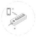
먼저, 본 발명을 실시하기 위한 전체 시스템의 구성에 대하여 도 1을 참조하여 설명한다.First, a configuration of an entire system for implementing the present invention will be described with reference to FIG. 1.
도 1에서 보는 바와 같이, 본 발명을 실시하기 위한 전체 시스템은 이동단말(10), 전자기기(20), 및, 멀티 콘센트(30)로 구성된다.As shown in FIG. 1, the entire system for implementing the present invention is composed of a
이동단말(10)은 사용자의 이동단말로서, 스마트폰 등 컴퓨팅 기능을 가지는 이동단말을 말한다. 이동단말(10)은 블루투스 또는 와이파이 등의 근거리 통신 기능을 구비하여, 멀티 콘센트(30)와 데이터 통신을 수행한다.The
전자기기(20)는 컴퓨터 본체, 모니터, 프린터, 텔레비전, 셋탑박스, 선풍기 등 전기를 사용하는 가전제품을 말한다. 전자기기(20)는 전력을 공급받는 플러그를 구비하여, 상기 플러그를 멀티 콘센트(30)의 접속구(40)에 연결함으로써 전력을 공급받는다.The
멀티 콘센트(30)는 다수의 접속구(40)를 구비하는 멀티 탭 등의 콘센트 장치로서, 접속구(40)에 플러그로 연결된 전자기기(20)에 전력을 공급하는 장치이다.The multi-outlet 30 is an outlet device such as a multi-tap having a plurality of
멀티 콘센트(30)는 이동단말(10)과 데이터 통신을 위한 무선 통신 기능을 구비하고, 이동단말(10)에 접속구(40)에 대한 정보 또는 데이터를 전송하거나, 이동단말(10)로부터 제어명령 등을 수신한다.The multi-outlet 30 has a wireless communication function for data communication with the
멀티 콘센트(30)는 블루투스 등을 통해 직접 이동단말(10)과 직접 통신을 하거나, 와이파이 등의 기능을 내장하여 네트워크(또는 액세스 포인트 장치) 등을 통해 데이터 통신을 수행할 수 있다.The multi-outlet 30 may directly communicate with the
또한, 멀티 콘센트(30)는 대기전력을 측정하는 전류계를 구비하여 각 접속구의 전류를 측정하고, 대기전력 수준 이하의 전류가 흐르면 해당 접속구의 전원을 차단한다. 이때, 접속구들 간에 마스터-슬레이브 관계를 설정하여, 마스터 접속구가 차단되면, 슬레이브 접속구도 전원을 차단하도록 설정한다.
In addition, the multi-outlet 30 is provided with an ammeter for measuring standby power to measure the current of each connector, and when a current below the standby power level flows, the power to the corresponding connector is cut off. At this time, a master-slave relationship is established between the connection ports, and when the master connection port is cut off, the slave connection port is also set to cut off power.
다음으로, 본 발명의 제1 실시예에 따른 마스터-슬레이브 관계 기반 대기전력 차단 멀티 콘센트 장치(30)의 구성을 도 2 내지 도 3을 참조하여 설명한다.Next, a configuration of a standby power blocking
도 2에서 보는 바와 같이, 멀티 콘센트 장치(30)는 교류 전압 수신용 플러그(31), 플러그(31)를 통하여 교류 전압을 공급하는 전선(32), 전선(32)과 연결되어 교류 전압을 공급받는 콘센트의 접속구(40)로 구성된다.As shown in FIG. 2, the
접속구(40)는 다수 개로 구성된다. 도 2에 도시된 멀티 콘센트 장치(30)의 접속구는 모두 5개로서, 이하에서, 각각의 개별 접속구의 도면부호를 각각 41,42,43,44,45로 표기한다.The
또한, 접속구(40)에 연결된 전선(32) 상에 스위치(50), 및, 전류계(60)가 구비된다. 스위치(50), 및 전류계(60) 각각은 하나의 접속구(40)에 연결되어, 해당 접속구(40)의 전원을 차단하거나, 전류를 측정한다. 이하에서, 각각 개별 스위치의 도면부호를 51,52,53,54,55로 표기하고, 각각 개별의 전류계의 도면 부호를 61,62,63,64,65로 표기한다.In addition, a switch 50 and an ammeter 60 are provided on the
또한, 도 3에서 보는 바와 같이, 멀티 콘센트 장치(30)의 내부에는 회로로 구성된 무선통신부(70) 및, 제어부(80)를 더 포함하여 구성된다.In addition, as shown in Figure 3, the interior of the
무선통신부(70)는 블루투스나 와이파이 등의 근거리 무선 통신 프로토콜에 의하여 근거리 무선 통신을 수행할 수 있는 장치이다.The
또한, 제어부(80)는 마이크로 컨트롤러, 또는 주문형 반도체(ASIC) 등으로 구현된 IC칩으로 실시된다.In addition, the
제어부(80)는 각 접속구(41,42,43,44,45)의 전류계(61,62,63,64,65)에서 측정되는 전류 크기(I1,I2,..., I5)를 입력받고, 입력된 전류에 따라 각 접속구의 스위치(51,52,53,54,55)에 차단 또는 연결의 제어 명령(C1,C2,...,C5)을 전송한다. 차단 명령인 경우, 해당 스위치는 해당 접속구에 공급되는 전원을 차단한다. 또한, 연결 명령인 경우, 접속구에 공급되는 전원을 공급하도록 해당 스위치를 연결해준다.The
즉, 제어부(80)는 각 전류계(61,62,63,64,65)로부터 전류를 측정하여, 측정된 전류가 기준치(대기전력의 기준치) 이하로 떨어지면, 해당 전류계(60)와 연결된 접속구(40)의 스위치(50)를 차단한다. 또한, 제어부(80)는 차단하는 접속구(40)와 종속관계에 있는 슬레이브 접속구(40)를 함께 차단한다.That is, the
한편, 제어부(80)는 각 접속구(41,42,43,44,45) 간의 마스터-슬레이브 관계를 이동단말(10)로부터 수신하여 저장한다. 이때, 무선통신부(70)를 통해 마스터-슬레이브 관계에 대한 데이터를 수신한다.Meanwhile, the
예를 들어, 접속구 41이 마스터 접속구이고, 접속구 43, 44는 접속구 41에 대한 슬레이브 접속구라고 설정될 수 있다. 이때, 제어부(80)는 접속구 41의 전원을 차단하는 경우, 제어부(80)는 접속구 41의 전원 차단과 동시에, 접속구 43,44도 함께 전원을 차단한다.For example, the
마스터와 슬레이브 관계는 겹쳐지지 않은 한, 복수의 마스터 접속구를 설정할 수 있다. 예를 들어, 접속구 41은 마스터 접속구이고 접속구 42는 접속구 41의 슬레이브 접속구로 설정되고, 접속구 44는 마스터 접속구이고 접속구 43과 45는 접속구 44의 슬레이브 접속구로 설정될 수 있다.As long as the master-slave relationship does not overlap, multiple master connection ports can be set. For example,
또한, 동일한 슬레이브 접속구에 대하여 적어도 2개 이상의 마스터 접속구와 마스터-슬레이브 관계를 가질 수도 있다. 예를 들어, 접속구 42가 접속구 41에 종속될 뿐만 아니라, 접속구 43에도 종속될 수 있다. 이때, 접속구 42는 접속구 41과 접속구 43 모두에서 대기전력으로 판단되어야, 전원을 차단시킬 수 있다.
In addition, it is also possible to have a master-slave relationship with at least two or more master connection ports for the same slave connection port. For example,
다음으로, 본 발명의 제1 실시예에 따른 마스터-슬레이브 관계 기반 대기전력 차단 멀티 콘센트 장치(30)에 의한 대기전력 차단 방법을 도 4를 참조하여 설명한다.Next, a method of blocking standby power by the standby power blocking
도 4에서 보는 바와 같이, 먼저, 멀티 콘센트 장치(30)의 제어부(80)는 대기전력 기준치를 설정한다(S11). 일례로서, 제어부(80)는 대기전력 기준치를 사전에 설정하여 저장해둔다.As shown in FIG. 4, first, the
또는, 다른 예로서, 사용자는 멀티탭에 접속된 모든 기기를 대기 상태에 두고, 제어부(80)에 대기전력설정 명령을 전송한다. 제어부(80)는 대기전력 설정 명령을 수신하면, 전류계(60)를 통해 각 접속구(40)의 전류를 측정하여, 측정된 전류를 대기전력의 기준치로 설정한다. 즉, 대기전력을 일률적으로 설정할 수 없는 경우, 각 접속구에 전자기기를 연결하되, 대기전력 상태로 유지한 후, 그때의 전류를 측정하여, 측정된 값을 기준치로 설정한다.Alternatively, as another example, the user puts all devices connected to the multi-tap in a standby state and transmits a standby power setting command to the
다음으로, 멀티 콘센트 장치(30)의 제어부(80)는 다수의 접속구(40) 간의 마스터-슬레이브 관계에 대한 데이터를 이동단말(10)로부터 수신하여 저장한다(S12). 이때, 제어부(80)은 무선통신부(70)를 통해 데이터를 수신한다.Next, the
다음으로, 제어부(80)는 주기적으로 각 접속구(40)의 전류계(60)를 통해 전류를 측정한다(S20). 그리고 측정된 접속구의 전류를 대기전력 기준치와 대비한다(S30). 만약 측정된 전류가 대기전력 기준치 보다 크면, 다시 일정한 주기 후에 전류를 측정한다. 이때, 각 접속구(40) 별로 전류를 측정하여 대비한다.Next, the
만약, 측정된 접속구(40)의 전류가 대기전력 기준치 이하가 되면, 제어부(80)는 해당 접속구(40)에 스위치 개방 신호를 전송한다. 그래서 해당 접속구의 전원을 차단한다(S40).If the measured current of the
또한, 제어부(80)는 저장된 마스터-슬레이브 관계를 검색하여, 차단되는 접속구와 종속 관계를 가지는 슬레이브 접속구가 있는지를 확인한다. 그래서 슬레이브로 확인된 접속구(40)의 전원도 차단시킨다(S50).In addition, the
한편, 상기 종속된 슬레이브 접속구가 상기 해당 마스터 접속구가 아닌 다른 마스터 접속구에도 종속되어 있으며, 다른 마스터 접속구가 대기 상태가 아닐 경우에는 스위치를 조작하지 않는다. 즉, 전원을 차단하지 않는다.
On the other hand, if the slave connection port is subordinate to a master connection port other than the corresponding master connection port, and the other master connection port is not in a standby state, the switch is not operated. In other words, it does not cut off the power.
다음으로, 본 발명의 제2 실시예에 따른 마스터-슬레이브 관계 기반 대기전력 차단 멀티 콘센트 장치(30)를 도 5를 참조하여 설명한다.Next, a standby power blocking
도 5에서 보는 바와 같이, 멀티 콘센트 장치(30)는 적어도 2개 이상의 멀티 콘센트로 구성된다. 이때, 하나의 멀티 콘센트의 제어부(80)는 무선통신부(70)를 통해 다른 멀티 콘센트의 제어부(80)와 데이터 통신을 수행한다.As shown in Figure 5, the
멀티 콘센트 장치(30)의 다른 구성은 앞서 제1 실시예와 동일하다. 이하에서, 제1 실시예와의 차이가 있는 부분만 설명한다. 따라서 설명되지 않은 부분은 제1 실시예의 구성을 참조한다.Other configurations of the
각 멀티 콘센트 장치(30)의 제어부는 마스터-슬레이브 관계에 대한 데이터를 수신하되, 슬레이브 접속구가 자신의 접속구 외에도 다른 멀티 콘센트 장치의 접속구도 포함할 수 있다.The control unit of each
도 5의 예에서, 멀티 콘센트 A의 접속구 A1은 슬레이브 접속구로서, 접속구 A2, A4, B1, B4로 구성된다. 따라서 멀티 콘센트 A의 제어부에서 접속구 A1이 대기전력으로 판단되면, 접속구 A1과 그 마스터-슬레이브 관계를 갖는 A2, A4의 접속구 전원을 차단한다. 또한, 멀티 콘센트 A의 제어부는 멀티 콘센트 B의 제어부로 접속구 B1, B4에 대한 차단 명령을 전송한다.In the example of Fig. 5, the connection port A1 of the multi-outlet A is a slave connection port, and is composed of the connection ports A2, A4, B1, and B4. Therefore, when the control unit of the multi-outlet A determines that the connection port A1 is standby power, the power of the connection port A1 and the connection ports A2 and A4 having a master-slave relationship is cut off. In addition, the control unit of the multi-outlet A transmits a cutoff command for the connection ports B1 and B4 to the control unit of the multi-outlet B.
멀티 콘센트 B는 자신의 접속구에 대한 차단 명령을 수신하면, 해당 접속구의 스위치를 개방하여 접속구를 차단한다.
When the multi-outlet B receives a blocking command for its own connection port, it opens the switch of the corresponding connection port to block the connection port.
다음으로, 본 발명의 제3 실시예에 따른 마스터-슬레이브 관계 기반 대기전력 차단 멀티 콘센트 장치(30)를 도 6을 참조하여 설명한다.Next, a standby power blocking
도 6에서 보는 바와 같이, 이동단말(10)이 멀티 콘센트 장치(30)와의 통신 반경 내에 있으면, 멀티 콘센트 장치(30)는 이동단말(10)과 데이터 통신이 가능하다. 즉, 멀티 콘센트 장치(30)의 제어부(80)는 이동단말(10)과 데이터 통신이 가능하면, 주변에 사용자가 있는 것으로 판단할 수 있다.As shown in FIG. 6, if the
이 경우, 멀티 콘센트 장치(30)는 접속구가 대기전력 상태이면, 해당 접속구 및 그 슬레이브 접속구의 대기전력 차단 여부를 이동단말(10)에 질의할 수 있다.In this case, when the connection port is in a standby power state, the
구체적으로, 접속구의 전력이 설정된 대기전력 이상에서 이하로 떨어지면, 제어부(80)는 설정된 마스터-슬레이브 관계에 따라 상기 접속구에 종속된 접속구들의 스위치의 개방 여부에 대해 이동단말(10)로 질의 메시지를 전송한다. 이동단말(10)이 멀티 탭과 연결되어있지 않으면 앞서 제1 실시예와 동일하게 동작한다.Specifically, when the power of the connection port falls from more than the set standby power to below, the
이동단말(10)은 질의 메시지를 수신하면, 그 질의 메시지에 대하여 사용자로부터 질의된 각 접속구의 스위치의 개방 여부를 입력받는다. 그리고 이동단말(10)은 개방 여부에 대한 입력을 멀티 콘센트 장치(30)의 제어부(80)로 전송한다.When the
제어부(80)는 수신한 입력에 따라 접속구의 스위치를 차단한다.
The
이상, 본 발명자에 의해서 이루어진 발명을 실시 예에 따라 구체적으로 설명하였지만, 본 발명은 실시 예에 한정되는 것은 아니고, 그 요지를 이탈하지 않는 범위에서 여러 가지로 변경 가능한 것은 물론이다.In the above, the invention made by the present inventors has been described in detail according to embodiments, but the present invention is not limited to the embodiments, and it goes without saying that various changes can be made without departing from the gist of the invention.
10 : 이동단말 20 : 전자기기
30 : 멀티 콘센트 장치 31 : 플러그
32 : 전선
40,41,42,43,44,45 : 접속구 50,51,52,53,54,55 : 스위치
60,61,62,63,64,65 : 전류계
70 : 무선통신부 80 : 제어부10: mobile terminal 20: electronic device
30: multi-outlet device 31: plug
32: wire
40,41,42,43,44,45:
60,61,62,63,64,65: ammeter
70: wireless communication unit 80: control unit
Claims (5)
Translated fromKorean적어도 2개의 접속구;
상기 각 접속구의 전류를 측정하는 전류계;
상기 각 접속구의 전원을 차단하는 스위치;
이동단말과 데이터 통신을 수행하는 무선통신부; 및,
상기 이동단말로부터 접속구들 간의 마스터-슬레이브 관계를 수신하여 저장하고, 상기 전류계로부터 측정된 전류에 의해 해당 접속구가 대기전력 상태로 판단되면, 해당 접속구 및, 상기 해당 접속구와 마스터-슬레이브 관계를 갖는 모든 슬레이브 접속구의 스위치를 개방하여 전원을 차단하게 하는 제어부를 포함하고,
상기 제어부는 다수의 접속구 간의 마스터-슬레이브 관계에 대한 데이터를 이동단말로부터 수신하여 저장하되, 상기 무선통신부를 통해 해당 데이터를 수신하고,
상기 제어부는 접속구의 전류가 대기전력 기준치 이하가 되면, 해당 접속구에 스위치 개방 신호를 전송하여 해당 접속구의 전원을 차단하고, 저장된 마스터-슬레이브 관계를 검색하여, 차단되는 접속구와 종속 관계를 가지는 슬레이브 접속구가 있는지를 확인하고, 슬레이브로 확인된 접속구의 전원도 차단시키고,
다수의 접속구 간의 마스터-슬레이브 관계는 상기 이동단말에 의해 전송되는 데이터에 의해 설정되어, 복수의 마스터 접속구를 설정하고, 동일한 슬레이브 접속구에 대하여 적어도 2개 이상의 마스터 접속구와 마스터-슬레이브 관계를 가지도록 설정되고,
상기 제어부는 상기 슬레이브 접속구와 마스터-슬레이브 관계를 갖는 마스터 접속구가 적어도 2개이면, 해당 슬레이브 접속구와 관계를 가지는 모든 마스터 접속구가 대기전력 상태이거나 스위치가 개방된 경우에 한하여, 상기 슬레이브 접속구의 스위치를 개방하는 것을 특징으로 하는 마스터-슬레이브 관계 기반 대기전력 차단 멀티 콘센트 장치.
In the standby power cut-off multi-outlet device based on a master-slave relationship,
At least two connectors;
An ammeter for measuring the current of each of the connection ports;
A switch to cut off power to each of the connection ports;
A wireless communication unit for performing data communication with a mobile terminal; And,
If the connection port is determined to be in standby power state by receiving and storing the master-slave relationship between the connection ports from the mobile terminal, and the current measured from the ammeter, the connection port and all of the connection ports and the master-slave relationship It includes a control unit to cut off power by opening a switch of the slave connection port,
The control unit receives and stores data on a master-slave relationship between a plurality of connection ports from a mobile terminal, and receives the data through the wireless communication unit,
When the current of the connection port falls below the standby power reference value, the control unit cuts off the power of the connection port by transmitting a switch open signal to the connection port, searches the saved master-slave relationship, and a slave connection port having a dependency relationship with the blocked connection port Check if there is, and cut off the power of the connection port identified as a slave,
The master-slave relationship between multiple connection ports is set by the data transmitted by the mobile terminal, and a plurality of master connection ports are set, and at least two or more master connection ports and master-slave relationships are set for the same slave connection port. Become,
If the slave connection port and the master connection port having a master-slave relationship are at least two, the control unit switches the slave connection port only when all the master connection ports related to the slave connection port are in standby power state or the switch is open. Standby power cut-off multi-outlet device based on a master-slave relationship, characterized in that opening.
상기 제어부는 상기 이동단말의 명령에 의하여, 현재 상태의 전류를 측정하여, 측정된 전류를 대기전력 기준치로 설정하고, 상기 대기전력 기준치를 상기 접속구의 대기전력 상태를 판단하는 기준으로 사용하는 것을 특징으로 하는 마스터-슬레이브 관계 기반 대기전력 차단 멀티 콘센트 장치.
The method of claim 1,
The control unit measures the current in the current state according to the command of the mobile terminal, sets the measured current as a standby power reference value, and uses the standby power reference value as a reference for determining the standby power state of the connection port. Standby power cut-off multi-outlet device based on master-slave relationship.
상기 제어부는 상기 이동단말과 통신이 가능하면, 상기 이동단말에 상기 접속구의 차단 여부를 질의하고, 상기 이동단말로부터 수신된 제어 명령에 의하여 상기 접속구의 차단 여부를 결정하는 것을 특징으로 하는 마스터-슬레이브 관계 기반 대기전력 차단 멀티 콘센트 장치.
The method of claim 1,
If communication with the mobile terminal is possible, the control unit queries the mobile terminal for blocking of the access port, and determines whether to block the access port according to a control command received from the mobile terminal. Relationship-based standby power cutoff multi-outlet device.
적어도 2개의 제1항의 대기전력 차단 멀티 콘센트 장치들을 포함하고,
상기 멀티 콘센트 장치들 중 하나인 제1 멀티 콘센트 장치의 제1 접속구는 마스터 접속구로서, 상기 멀티 콘센트 장치들 중 다른 하나인 제2 멀티 콘센트 장치의 제2 접속구와 마스터-슬레이브 관계를 갖고,
상기 제1 멀티 콘센트 장치의 제어부는 상기 제1 접속구가 대기전력 상태이면, 상기 제1 접속구의 스위치를 개방하여 전원을 차단하고, 상기 제2 멀티 콘센트 장치의 제어부에 상기 제2 접속구를 차단하라는 명령을 전송하는 것을 특징으로 하는 마스터-슬레이브 관계 기반 대기전력 차단 멀티 콘센트 시스템.
As a standby power cutoff multi-outlet system based on a master-slave relationship,
Including at least two standby power cut-off multi-outlet devices of claim 1,
The first connection port of the first multi-outlet device, which is one of the multi-outlet devices, is a master connection port, and has a master-slave relationship with the second connection port of the second multi-outlet device, which is another one of the multi-outlet devices,
When the first connection port is in standby power state, the control unit of the first multi-outlet device cuts off power by opening a switch of the first connection port, and commands the control unit of the second multi-outlet device to cut off the second connection port. A master-slave relationship-based standby power cut-off multi-outlet system, characterized in that for transmitting.
Priority Applications (1)
| Application Number | Priority Date | Filing Date | Title |
|---|---|---|---|
| KR1020140118010AKR102239636B1 (en) | 2014-09-04 | 2014-09-04 | A multi outlet device for controlling standby power of electric appliances with master and slave relationship |
Applications Claiming Priority (1)
| Application Number | Priority Date | Filing Date | Title |
|---|---|---|---|
| KR1020140118010AKR102239636B1 (en) | 2014-09-04 | 2014-09-04 | A multi outlet device for controlling standby power of electric appliances with master and slave relationship |
Publications (2)
| Publication Number | Publication Date |
|---|---|
| KR20160028893A KR20160028893A (en) | 2016-03-14 |
| KR102239636B1true KR102239636B1 (en) | 2021-04-12 |
Family
ID=55541622
Family Applications (1)
| Application Number | Title | Priority Date | Filing Date |
|---|---|---|---|
| KR1020140118010AActiveKR102239636B1 (en) | 2014-09-04 | 2014-09-04 | A multi outlet device for controlling standby power of electric appliances with master and slave relationship |
Country Status (1)
| Country | Link |
|---|---|
| KR (1) | KR102239636B1 (en) |
Families Citing this family (2)
| Publication number | Priority date | Publication date | Assignee | Title |
|---|---|---|---|---|
| US10587118B2 (en) | 2016-11-15 | 2020-03-10 | Solaredge Technologies Ltd. | Smart outlet |
| KR102109801B1 (en)* | 2018-11-06 | 2020-05-13 | 주식회사 썬플라워즈 | Apparatus of smart socket |
Citations (2)
| Publication number | Priority date | Publication date | Assignee | Title |
|---|---|---|---|---|
| JP2010157485A (en) | 2008-12-31 | 2010-07-15 | Powertech Industrial Co Ltd | Wireless-controlled power-saving socket, wireless power detection controller, and wireless-controlled power-saving device integrally incorporated with these |
| KR101358834B1 (en)* | 2013-07-02 | 2014-02-05 | (주)성진엠케이 | Automatic block system for standby power and power saving control method thereof |
Family Cites Families (6)
| Publication number | Priority date | Publication date | Assignee | Title |
|---|---|---|---|---|
| KR100983964B1 (en)* | 2008-01-10 | 2010-09-27 | 정중호 | Intelligent power strips and power outlets with wired and wireless control |
| KR20130013908A (en) | 2011-07-29 | 2013-02-06 | 삼성물산 주식회사 | System for wirelessly controllng standby-power using smart device |
| KR101322471B1 (en)* | 2012-02-21 | 2013-10-28 | 경운대학교 산학협력단 | Standby Power saving concert with short-range communication |
| KR20130110763A (en) | 2012-03-30 | 2013-10-10 | (주)세오전자 | Remote control system contain touch switch for light control and smart outlet for cut-off standby power |
| KR101376132B1 (en) | 2012-07-19 | 2014-03-19 | 대신네트웍스 주식회사 | Multi-outlet device for controlling standby power of electric applliances by using remote controller |
| KR101384862B1 (en) | 2012-09-28 | 2014-04-15 | 임대섭 | Electric outlet apparatus for intercepting standby power |
- 2014
- 2014-09-04KRKR1020140118010Apatent/KR102239636B1/enactiveActive
Patent Citations (2)
| Publication number | Priority date | Publication date | Assignee | Title |
|---|---|---|---|---|
| JP2010157485A (en) | 2008-12-31 | 2010-07-15 | Powertech Industrial Co Ltd | Wireless-controlled power-saving socket, wireless power detection controller, and wireless-controlled power-saving device integrally incorporated with these |
| KR101358834B1 (en)* | 2013-07-02 | 2014-02-05 | (주)성진엠케이 | Automatic block system for standby power and power saving control method thereof |
Also Published As
| Publication number | Publication date |
|---|---|
| KR20160028893A (en) | 2016-03-14 |
Similar Documents
| Publication | Publication Date | Title |
|---|---|---|
| US9634738B2 (en) | Hybrid power line/wireless appliance automation system, device, and power monitoring method utilizing the same | |
| US8093751B1 (en) | Method and system for controlling power to an electrically powered device | |
| US10431940B1 (en) | Power receptacle with wireless control | |
| US20130234534A1 (en) | Power socket with wireless communication capability, system having the same and method thereof | |
| US20130339766A1 (en) | Power supply dock with wireless network and power management functions | |
| KR101035127B1 (en) | Power saving outlet device with remote control | |
| US9159222B2 (en) | Method and apparatus for wireless remote control of an electric appliance | |
| CN103794955B (en) | Intelligent power supply system and Intelligent socket thereof and intelligent power supply method | |
| KR102239636B1 (en) | A multi outlet device for controlling standby power of electric appliances with master and slave relationship | |
| US9444893B2 (en) | Network power control module | |
| US7468567B1 (en) | Power switching apparatus and network equipment | |
| KR101479659B1 (en) | Method for individual and group controlling for multitap based on wireless communication and individual multitap and multitap group controlled based on wireless communication | |
| TWI497860B (en) | A power monitoring system | |
| KR101264062B1 (en) | Auto control multi-socket device for sharing internet protocol usage, desk with multi-socket device for sharing internet protocol usage, and personalized smart grid system using multi-socket device for sharing internet protocol usage | |
| JP3211607U (en) | Standby circuit, socket, plug and device having the standby circuit | |
| CN203455685U (en) | Multiport Power Monitor | |
| CN104283071A (en) | Energy-saving socket with WIFI hot spot function | |
| KR101127641B1 (en) | A system and method for controlling standby power of consents installed on the floor | |
| KR20180092703A (en) | Power supply control apparatus and method thereof | |
| CN202712617U (en) | Remote control switch system of wall socket | |
| KR20150082988A (en) | power saving interface using wireless communication | |
| KR101485025B1 (en) | Power control apparatus for multi-tap and method thereof | |
| KR20150005345A (en) | Power managing apparatus and power managing system using the same | |
| TWM468001U (en) | Energy saving switch | |
| WO2019169606A1 (en) | Smart socket, and smart socket assembly |
Legal Events
| Date | Code | Title | Description |
|---|---|---|---|
| PA0109 | Patent application | Patent event code:PA01091R01D Comment text:Patent Application Patent event date:20140904 | |
| PG1501 | Laying open of application | ||
| PA0201 | Request for examination | Patent event code:PA02012R01D Patent event date:20190711 Comment text:Request for Examination of Application Patent event code:PA02011R01I Patent event date:20140904 Comment text:Patent Application | |
| E902 | Notification of reason for refusal | ||
| PE0902 | Notice of grounds for rejection | Comment text:Notification of reason for refusal Patent event date:20201116 Patent event code:PE09021S01D | |
| E701 | Decision to grant or registration of patent right | ||
| PE0701 | Decision of registration | Patent event code:PE07011S01D Comment text:Decision to Grant Registration Patent event date:20210201 | |
| GRNT | Written decision to grant | ||
| PR0701 | Registration of establishment | Comment text:Registration of Establishment Patent event date:20210407 Patent event code:PR07011E01D | |
| PR1002 | Payment of registration fee | Payment date:20210407 End annual number:3 Start annual number:1 | |
| PG1601 | Publication of registration | ||
| PR1001 | Payment of annual fee | Payment date:20240110 Start annual number:4 End annual number:4 | |
| PR1001 | Payment of annual fee | Payment date:20250407 Start annual number:5 End annual number:5 |