KR102229864B1 - Free space optical transmitter/receiver based on polarization position and differential phase shift keying and transmitting/receiving method thereof - Google Patents
Free space optical transmitter/receiver based on polarization position and differential phase shift keying and transmitting/receiving method thereofDownload PDFInfo
- Publication number
- KR102229864B1 KR102229864B1KR1020200008370AKR20200008370AKR102229864B1KR 102229864 B1KR102229864 B1KR 102229864B1KR 1020200008370 AKR1020200008370 AKR 1020200008370AKR 20200008370 AKR20200008370 AKR 20200008370AKR 102229864 B1KR102229864 B1KR 102229864B1
- Authority
- KR
- South Korea
- Prior art keywords
- phase
- light
- polarization
- bit
- data
- Prior art date
- Legal status (The legal status is an assumption and is not a legal conclusion. Google has not performed a legal analysis and makes no representation as to the accuracy of the status listed.)
- Active
Links
Images


Classifications
- H—ELECTRICITY
- H04—ELECTRIC COMMUNICATION TECHNIQUE
- H04B—TRANSMISSION
- H04B10/00—Transmission systems employing electromagnetic waves other than radio-waves, e.g. infrared, visible or ultraviolet light, or employing corpuscular radiation, e.g. quantum communication
- H04B10/50—Transmitters
- H04B10/516—Details of coding or modulation
- H04B10/5161—Combination of different modulation schemes
- H—ELECTRICITY
- H01—ELECTRIC ELEMENTS
- H01S—DEVICES USING THE PROCESS OF LIGHT AMPLIFICATION BY STIMULATED EMISSION OF RADIATION [LASER] TO AMPLIFY OR GENERATE LIGHT; DEVICES USING STIMULATED EMISSION OF ELECTROMAGNETIC RADIATION IN WAVE RANGES OTHER THAN OPTICAL
- H01S3/00—Lasers, i.e. devices using stimulated emission of electromagnetic radiation in the infrared, visible or ultraviolet wave range
- H01S3/05—Construction or shape of optical resonators; Accommodation of active medium therein; Shape of active medium
- H01S3/06—Construction or shape of active medium
- H01S3/063—Waveguide lasers, i.e. whereby the dimensions of the waveguide are of the order of the light wavelength
- H01S3/067—Fibre lasers
- H01S3/06754—Fibre amplifiers
- H—ELECTRICITY
- H01—ELECTRIC ELEMENTS
- H01S—DEVICES USING THE PROCESS OF LIGHT AMPLIFICATION BY STIMULATED EMISSION OF RADIATION [LASER] TO AMPLIFY OR GENERATE LIGHT; DEVICES USING STIMULATED EMISSION OF ELECTROMAGNETIC RADIATION IN WAVE RANGES OTHER THAN OPTICAL
- H01S3/00—Lasers, i.e. devices using stimulated emission of electromagnetic radiation in the infrared, visible or ultraviolet wave range
- H01S3/14—Lasers, i.e. devices using stimulated emission of electromagnetic radiation in the infrared, visible or ultraviolet wave range characterised by the material used as the active medium
- H01S3/16—Solid materials
- H01S3/1601—Solid materials characterised by an active (lasing) ion
- H01S3/1603—Solid materials characterised by an active (lasing) ion rare earth
- H01S3/1608—Solid materials characterised by an active (lasing) ion rare earth erbium
- H—ELECTRICITY
- H04—ELECTRIC COMMUNICATION TECHNIQUE
- H04B—TRANSMISSION
- H04B10/00—Transmission systems employing electromagnetic waves other than radio-waves, e.g. infrared, visible or ultraviolet light, or employing corpuscular radiation, e.g. quantum communication
- H04B10/25—Arrangements specific to fibre transmission
- H04B10/2507—Arrangements specific to fibre transmission for the reduction or elimination of distortion or dispersion
- H04B10/2569—Arrangements specific to fibre transmission for the reduction or elimination of distortion or dispersion due to polarisation mode dispersion [PMD]
- H—ELECTRICITY
- H04—ELECTRIC COMMUNICATION TECHNIQUE
- H04B—TRANSMISSION
- H04B10/00—Transmission systems employing electromagnetic waves other than radio-waves, e.g. infrared, visible or ultraviolet light, or employing corpuscular radiation, e.g. quantum communication
- H04B10/50—Transmitters
- H04B10/501—Structural aspects
- H04B10/503—Laser transmitters
- H—ELECTRICITY
- H04—ELECTRIC COMMUNICATION TECHNIQUE
- H04B—TRANSMISSION
- H04B10/00—Transmission systems employing electromagnetic waves other than radio-waves, e.g. infrared, visible or ultraviolet light, or employing corpuscular radiation, e.g. quantum communication
- H04B10/50—Transmitters
- H04B10/516—Details of coding or modulation
- H04B10/548—Phase or frequency modulation
- H04B10/556—Digital modulation, e.g. differential phase shift keying [DPSK] or frequency shift keying [FSK]
- H04B10/5561—Digital phase modulation
- H—ELECTRICITY
- H04—ELECTRIC COMMUNICATION TECHNIQUE
- H04B—TRANSMISSION
- H04B10/00—Transmission systems employing electromagnetic waves other than radio-waves, e.g. infrared, visible or ultraviolet light, or employing corpuscular radiation, e.g. quantum communication
- H04B10/60—Receivers
- H04B10/66—Non-coherent receivers, e.g. using direct detection
- H04B10/67—Optical arrangements in the receiver
- H04B10/676—Optical arrangements in the receiver for all-optical demodulation of the input optical signal
- H04B10/677—Optical arrangements in the receiver for all-optical demodulation of the input optical signal for differentially modulated signal, e.g. DPSK signals
- H—ELECTRICITY
- H04—ELECTRIC COMMUNICATION TECHNIQUE
- H04B—TRANSMISSION
- H04B10/00—Transmission systems employing electromagnetic waves other than radio-waves, e.g. infrared, visible or ultraviolet light, or employing corpuscular radiation, e.g. quantum communication
- H04B10/60—Receivers
- H04B10/66—Non-coherent receivers, e.g. using direct detection
- H04B10/69—Electrical arrangements in the receiver
- H04B10/691—Arrangements for optimizing the photodetector in the receiver
- G—PHYSICS
- G02—OPTICS
- G02B—OPTICAL ELEMENTS, SYSTEMS OR APPARATUS
- G02B27/00—Optical systems or apparatus not provided for by any of the groups G02B1/00 - G02B26/00, G02B30/00
- G02B27/28—Optical systems or apparatus not provided for by any of the groups G02B1/00 - G02B26/00, G02B30/00 for polarising
- G02B27/283—Optical systems or apparatus not provided for by any of the groups G02B1/00 - G02B26/00, G02B30/00 for polarising used for beam splitting or combining
- H—ELECTRICITY
- H04—ELECTRIC COMMUNICATION TECHNIQUE
- H04B—TRANSMISSION
- H04B10/00—Transmission systems employing electromagnetic waves other than radio-waves, e.g. infrared, visible or ultraviolet light, or employing corpuscular radiation, e.g. quantum communication
- H04B10/11—Arrangements specific to free-space transmission, i.e. transmission through air or vacuum
- H—ELECTRICITY
- H04—ELECTRIC COMMUNICATION TECHNIQUE
- H04B—TRANSMISSION
- H04B10/00—Transmission systems employing electromagnetic waves other than radio-waves, e.g. infrared, visible or ultraviolet light, or employing corpuscular radiation, e.g. quantum communication
- H04B10/50—Transmitters
- H04B10/516—Details of coding or modulation
- H04B10/524—Pulse modulation
- H—ELECTRICITY
- H04—ELECTRIC COMMUNICATION TECHNIQUE
- H04B—TRANSMISSION
- H04B10/00—Transmission systems employing electromagnetic waves other than radio-waves, e.g. infrared, visible or ultraviolet light, or employing corpuscular radiation, e.g. quantum communication
- H04B10/50—Transmitters
- H04B10/516—Details of coding or modulation
- H04B10/532—Polarisation modulation
- H—ELECTRICITY
- H04—ELECTRIC COMMUNICATION TECHNIQUE
- H04B—TRANSMISSION
- H04B10/00—Transmission systems employing electromagnetic waves other than radio-waves, e.g. infrared, visible or ultraviolet light, or employing corpuscular radiation, e.g. quantum communication
- H04B10/50—Transmitters
- H04B10/516—Details of coding or modulation
- H04B10/548—Phase or frequency modulation
- H04B10/556—Digital modulation, e.g. differential phase shift keying [DPSK] or frequency shift keying [FSK]
Landscapes
- Physics & Mathematics (AREA)
- Electromagnetism (AREA)
- Engineering & Computer Science (AREA)
- Computer Networks & Wireless Communication (AREA)
- Signal Processing (AREA)
- Optics & Photonics (AREA)
- Plasma & Fusion (AREA)
- General Physics & Mathematics (AREA)
- Optical Communication System (AREA)
Abstract
Description
Translated fromKorean본 발명은 무선 광 통신 시스템 및 방법에 관한 것으로, 편광 위치 및 차동 위상 편이 변조 기반 무선 광 통신 시스템 및 방법에 관한 것이다.The present invention relates to a wireless optical communication system and method, and to a wireless optical communication system and method based on polarization position and differential phase shift modulation.
현재 광 통신에서는 연속하는 인접 심볼 사이의 편광 상태를 변화시켜 위상 변조하는 차동 위상 천이 변조(Differential Phase Shift Keying: 이하 DPSK) 기법이 주로 이용되고 있다. 다만 무선 광통신의 경우, 대기 채널이 안정적이지 않고 시간에 따라 지속적으로 변화하므로, 전송 속도를 채널 상태에 맞춰 변화시킬 수 있어야 한다. 그러나 DPSK 변조 기법에서는 수신기가 연속하는 인섭 심볼 사이의 편광 상태 변화를 검출하기 위해 지연 라인 간섭계(delay-line interferometer)를 사용하므로, 지연 라인 간섭계의 지연 시간을 조절하기 어려워 다중 전송 속도(multi-rate)를 구현하는데 어려움이 있다.Currently, in optical communication, a differential phase shift keying (DPSK) technique in which a polarization state between consecutive adjacent symbols is changed and phase-modulated is mainly used. However, in the case of wireless optical communication, since the standby channel is not stable and constantly changes over time, the transmission speed must be changed according to the channel state. However, in the DPSK modulation scheme, since the receiver uses a delay-line interferometer to detect changes in the polarization state between successive interference symbols, it is difficult to control the delay time of the delay line interferometer. ) Is difficult to implement.
이러한 한계를 극복하고자, 편광 회전(polarization rotation) 기반 DPSK 기법이 고안되었다. 편광 회전 기반 DPSK 기법에서는 광원에서 방출된 광을 서로 수직한 두 편광으로 분할하고, 분할된 두 편광 중 적어도 하나를 위상 변조하여 전송한다. 그리고 수신기에서는 수직한 두 편광을 하나의 편광으로 결합하여 위상차를 검출하여 데이터를 복조한다. 이러한 편광 회전 기반 DPSK 기법은 지연 라인 간섭계를 사용하지 않으므로, 용이하게 다중 전송 속도를 구현할 수 있다.To overcome this limitation, a polarization rotation-based DPSK technique was devised. In the polarization rotation-based DPSK technique, light emitted from a light source is divided into two polarizations perpendicular to each other, and at least one of the divided polarizations is phase-modulated and transmitted. In addition, the receiver combines the two vertically polarized light into one polarized light to detect the phase difference and demodulate the data. Since this polarization rotation-based DPSK technique does not use a delay line interferometer, it is possible to easily implement multiple transmission rates.
한편 장거리 무선 광 통신의 경우에는 대기 채널을 통과하는 동안 광 감쇄가 크게 발생하므로, 광원의 출력 파워만으로는 안정적인 채널 링크를 구성하기가 어렵다. 이에 송신기는 변조된 광을 증폭하여 출력하는 어듐 첨가 광 증폭기(Erbium Doped Fiber Amplifier: 이하 EDFA)와 같은 광 증폭기를 사용한다. 그러나 EDFA와 같은 광 증폭기는 평균 전력(Average Power)이 제한(limited)되는 특성을 갖는다. 이와 같이, 송신기가 평균 전력 제한 특성을 갖는 EDFA를 사용하는 경우, 편광 회전 기반 DPSK 기법을 적용할지라도 EDFA의 제한된 평균 전력에 의해 신호대 잡음비를 향상시킬 수 없으며, 이로 인해 전송 속도를 더 이상 높일 수 없게 된다. 즉 지연 라인 간섭계를 이용하지 않는 편광 회전 기반 DPSK 기법을 적용하더라도 전송 속도를 향상시키는데 한계가 있다.Meanwhile, in the case of long-distance wireless optical communication, since light attenuation greatly occurs while passing through an atmospheric channel, it is difficult to construct a stable channel link only with the output power of the light source. Accordingly, the transmitter uses an optical amplifier such as an Erbium Doped Fiber Amplifier (EDFA) that amplifies and outputs the modulated light. However, optical amplifiers such as EDFA have a characteristic that average power is limited. As described above, when the transmitter uses the EDFA having the average power limitation, even if the polarization rotation-based DPSK technique is applied, the signal-to-noise ratio cannot be improved due to the limited average power of the EDFA, and thus the transmission speed can be further increased. There will be no. That is, even if a polarization rotation-based DPSK technique that does not use a delay line interferometer is applied, there is a limitation in improving the transmission speed.
본 발명의 목적은 광 증폭기의 평균 전력 한계를 극복하여 신호대 잡음비를 개선할 수 있는 무선 광 송수신 장치 및 방법을 제공하는데 있다.An object of the present invention is to provide a wireless optical transmission/reception apparatus and method capable of improving a signal-to-noise ratio by overcoming the average power limitation of an optical amplifier.
본 발명의 다른 목적은 전송 속도를 대폭 향상시킬 수 있는 무선 광 송수신 장치 및 방법을 제공하는데 있다.Another object of the present invention is to provide a wireless optical transmission/reception apparatus and method capable of significantly improving a transmission speed.
상기 목적을 달성하기 위한 본 발명의 일 실시예에 따른 무선 광 송신 장치는 광원에서 방출된 광을 2개의 광으로 분배하는 광 분배기; 입력 데이터를 기지정된 비트 수의 심볼 단위의 다수의 분할 데이터로 분할하고, 각 분할 데이터에서 기지정된 위치의 위상 비트와 나머지 비트인 듀티 비트의 값을 각각 위상 제어 신호 및 차단 제어 신호로 변환하는 데이터 변환부; 상기 위상 제어 신호에 따라 분배된 2개의 광을 편광 위상 변조하고, 변조된 2개의 편광을 차단 제어 신호에 응답하여 전달하거나 차단하여 펄스 위치 변조하는 변조부; 편광 위상 변조 및 펄스 위치 변조된 2개의 편광을 결합하여 송신 광 신호를 생성하는 편광 결합부; 및 상기 송신 광 신호를 증폭하여 대기 채널을 통해 송출하는 광 증폭부를 포함한다.A wireless light transmission apparatus according to an embodiment of the present invention for achieving the above object comprises: an optical splitter for distributing light emitted from a light source into two lights; Data that divides the input data into a number of divided data in symbol units of a predetermined number of bits, and converts the value of the phase bit at a predetermined position and the duty bit, which is the remaining bits, into a phase control signal and a blocking control signal, respectively. Conversion unit; A modulator for polarization phase modulation of the two light distributed according to the phase control signal, and transmitting or blocking the two modulated polarized light in response to a blocking control signal to modulate a pulse position; A polarization combiner configured to generate a transmission optical signal by combining the polarization phase-modulated and pulse-position-modulated polarized light; And an optical amplifying unit amplifying the transmission optical signal and transmitting it through an atmospheric channel.
상기 데이터 변환부는 상기 송신 광 신호의 심볼 구간을 분할하는 슬롯의 개수에 대응하는 비트 수로 지정된 상기 심볼 단위로 상기 입력 데이터를 다수의 분할 데이터로 분할하고, 각 분할 데이터에서 위상 비트의 비트값에 따라 동일한 2개의 위상 제어 신호를 출력하거나 서로 다른 2개의 위상 제어 신호를 출력할 수 있다.The data conversion unit divides the input data into a plurality of divided data in units of the symbol designated by the number of bits corresponding to the number of slots for dividing the symbol section of the transmission optical signal, and according to the bit value of the phase bit in each divided data. The same two phase control signals may be output or two different phase control signals may be output.
상기 데이터 변환부는 상기 듀티 비트의 비트값에 따라 심볼 구간에서 분할된 다수의 슬롯 중 변조된 2개의 편광이 전송될 슬롯을 결정하며, 결정된 슬롯을 제외한 나머지 슬롯에 대응하는 구간에 상기 차단 제어 신호를 출력할 수 있다.The data converter determines a slot to which two modulated polarizations are to be transmitted among a plurality of slots divided in a symbol section according to the bit value of the duty bit, and transmits the blocking control signal in a section corresponding to the remaining slots excluding the determined slot. Can be printed.
상기 변조부는 상기 위상 제어 신호에 응답하여, 분배된 2개의 광을 서로 동일하거나 수직한 위상차를 갖는 2개의 편광으로 편광 위상 변조하여 출력하는 위상 변조부; 및 차단 제어 신호에 응답하여, 변조된 2개의 편광을 전달되는 시간 구간을 조절하여 펄스 위치 변조하는 펄스 위치 변조부를 포함할 수 있다.In response to the phase control signal, the modulator comprises a phase modulator configured to perform polarization phase modulation of the two distributed lights into two polarized lights having a phase difference equal to or perpendicular to each other, and outputting the polarized light; And a pulse position modulator configured to modulate a pulse position by adjusting a time period in which the two modulated polarizations are transmitted in response to the blocking control signal.
상기 광 증폭부는 어듐 첨가 광 증폭기(Erbium Doped Fiber Amplifier: EDFA)로 구현될 수 있다.The optical amplification unit may be implemented as an Erbium Doped Fiber Amplifier (EDFA).
상기 목적을 달성하기 위한 본 발명의 다른 실시예에 따른 무선 광 수신 장치는 대기 채널을 통해 단속적으로 수신되는 수신 광 신호에서 기지정된 위상의 편광을 추출하는 편광 조절기; 상기 편광 조절기에서 추출된 편광을 서로 수직한 2개의 편광으로 분배하는 편광 분배기; 분배된 2개의 편광 중 하나의 편광의 위상을 90도 회전하는 편광 회전부; 분배된 2개의 편광 중 나머지 편광과 위상이 회전된 편광을 서로 차감하여 광을 검출하는 광 검출부; 및 수신된 광 신호의 심볼 구간을 분할한 다수의 슬롯 중 광이 검출되는 구간에 대응하는 슬롯의 위치와 광이 검출되는 구간의 편광에 따라, 기지정된 심볼 단위의 비트 수를 갖는 분할 데이터 단위로 데이터를 복원하는 데이터 복원부를 포함한다.A wireless light receiving apparatus according to another embodiment of the present invention for achieving the above object includes: a polarization adjuster for extracting polarization of a predetermined phase from a received optical signal intermittently received through an atmospheric channel; A polarization splitter for distributing the polarized light extracted from the polarization controller into two polarized light perpendicular to each other; A polarization rotating unit that rotates a phase of one polarized light of the divided polarized light by 90 degrees; A light detector configured to detect light by subtracting the remaining polarized light and the polarized light whose phase is rotated among the two distributed polarized light; And a divided data unit having a predetermined number of bits in a symbol unit according to a position of a slot corresponding to a section in which light is detected among a plurality of slots in which the symbol section of the received optical signal is divided and the polarization of the section in which light is detected. And a data restoration unit for restoring data.
상기 목적을 달성하기 위한 본 발명의 또 다른 실시예에 따른 무선 광 송신 방법은 광원에서 방출된 광을 2개의 광으로 분배하는 단계; 입력 데이터를 기지정된 비트 수의 심볼 단위의 다수의 분할 데이터로 분할하고, 각 분할 데이터에서 기지정된 위치의 위상 비트와 나머지 비트인 듀티 비트의 값을 각각 위상 제어 신호 및 차단 제어 신호로 변환하는 단계; 상기 위상 제어 신호에 따라 분배된 2개의 광을 편광 위상 변조하고, 변조된 2개의 편광을 차단 제어 신호에 응답하여 전달하거나 차단하여 펄스 위치 변조하는 단계; 편광 위상 변조 및 펄스 위치 변조된 2개의 편광을 결합하여 송신 광 신호를 생성하는 단계; 및 상기 송신 광 신호를 증폭하여 대기 채널을 통해 송출하는 단계를 포함한다.A wireless light transmission method according to another embodiment of the present invention for achieving the above object includes the steps of distributing light emitted from a light source into two lights; Dividing the input data into a plurality of divided data in symbol units of a predetermined number of bits, and converting the value of the phase bit at a predetermined position and the duty bit, which is the remaining bits, into a phase control signal and a blocking control signal, respectively. ; Polarizing and phase-modulating two light distributed according to the phase control signal, and transmitting or blocking the two modulated polarized light in response to a blocking control signal to modulate a pulse position; Generating a transmission optical signal by combining the polarization phase-modulated and the pulse-position-modulated two polarizations; And amplifying the transmission optical signal and transmitting it through a standby channel.
상기 목적을 달성하기 위한 본 발명의 또 다른 실시예에 따른 무선 광 수신 방법은 대기 채널을 통해 단속적으로 수신되는 수신 광 신호에서 기지정된 위상의 편광을 추출하는 단계; 추출된 편광을 서로 수직한 2개의 편광으로 분배하는 단계; 분배된 2개의 편광 중 하나의 편광의 위상을 90도 회전시키는 단계; 분배된 2개의 편광 중 나머지 편광과 위상이 회전된 편광을 서로 차감하여 광을 검출하는 단계; 및 수신된 광 신호의 심볼 구간을 분할한 다수의 슬롯 중 광이 검출되는 구간에 대응하는 슬롯의 위치와 광이 검출되는 구간의 편광에 따라, 기지정된 심볼 단위의 비트 수를 갖는 분할 데이터 단위로 데이터를 복원하는 단계를 포함한다.A wireless light receiving method according to another embodiment of the present invention for achieving the above object includes: extracting a polarization of a predetermined phase from a received optical signal intermittently received through an atmospheric channel; Distributing the extracted polarized light into two polarized light perpendicular to each other; Rotating the phase of one of the two distributed polarizations by 90 degrees; Detecting light by subtracting the remaining polarized light and the polarized light whose phase is rotated among the two distributed polarized light; And divided data units having a predetermined number of bits in a symbol unit according to a position of a slot corresponding to a section in which light is detected among a plurality of slots in which the symbol section of the received optical signal is divided and the polarization of the section in which light is detected And restoring the data.
따라서, 본 발명의 실시예에 따른 무선 광 송수신 장치 및 방법은 편광 회전 기반 DPSK 기법과 함께 듀티 사이클 기반 변조를 함께 적용하는 편광 위치 및 차동 위상 편이 기법으로 변조 및 복조를 수행함으로써, 광 증폭기의 평균 전력 한계를 초과하지 않으면서 신호대 잡음비를 개선할 수 있을 뿐만 아니라 전송 속도를 대폭 향상시킬 수 있다.Accordingly, the apparatus and method of the wireless optical transmission and reception according to an embodiment of the present invention perform modulation and demodulation using a polarization position and a differential phase shift technique that applies duty cycle-based modulation together with a polarization rotation-based DPSK technique, thereby performing the average of the optical amplifier. Not only can the signal-to-noise ratio be improved without exceeding the power limit, but the transmission speed can be greatly improved.
도 1은 본 발명의 일 실시예에 따른 무선 광 통신 시스템에서 송신기의 개략적 구조를 나타낸다.
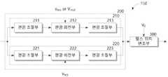
도 2는 도 1의 변조부의 상세 구성을 나타낸다.
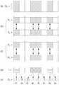
도 3은 도 1의 송신기가 데이터를 변조하는 일 예를 나타낸다.
도 4는 도 1의 송신기에서 변조된 광 신호의 특성을 나타낸다.
도 5는 본 발명의 일 실시예에 따른 무선 광 통신 시스템에서 수신기의 개략적 구조를 나타낸다.
도 6은 도 5의 수신기가 데이터를 복조하는 일 예를 나타낸다.
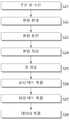
도 7은 본 발명의 일 실시예에 따른 무선 광 통신 시스템의 송신 방법을 나타낸다.
도 8은 본 발명의 일 실시예에 따른 무선 광 통신 시스템의 수신 방법을 나타낸다.1 shows a schematic structure of a transmitter in a wireless optical communication system according to an embodiment of the present invention.
2 shows a detailed configuration of the modulator of FIG. 1.
3 shows an example in which the transmitter of FIG. 1 modulates data.
4 shows characteristics of an optical signal modulated by the transmitter of FIG. 1.
5 shows a schematic structure of a receiver in a wireless optical communication system according to an embodiment of the present invention.
6 shows an example in which the receiver of FIG. 5 demodulates data.
7 shows a transmission method of a wireless optical communication system according to an embodiment of the present invention.
8 shows a method of receiving a wireless optical communication system according to an embodiment of the present invention.
본 발명과 본 발명의 동작상의 이점 및 본 발명의 실시에 의하여 달성되는 목적을 충분히 이해하기 위해서는 본 발명의 바람직한 실시예를 예시하는 첨부 도면 및 첨부 도면에 기재된 내용을 참조하여야만 한다.In order to fully understand the present invention, operational advantages of the present invention, and objects achieved by the implementation of the present invention, reference should be made to the accompanying drawings illustrating preferred embodiments of the present invention and the contents described in the accompanying drawings.
이하, 첨부한 도면을 참조하여 본 발명의 바람직한 실시예를 설명함으로써, 본 발명을 상세히 설명한다. 그러나, 본 발명은 여러 가지 상이한 형태로 구현될 수 있으며, 설명하는 실시예에 한정되는 것이 아니다. 그리고, 본 발명을 명확하게 설명하기 위하여 설명과 관계없는 부분은 생략되며, 도면의 동일한 참조부호는 동일한 부재임을 나타낸다.Hereinafter, the present invention will be described in detail by describing a preferred embodiment of the present invention with reference to the accompanying drawings. However, the present invention may be implemented in various different forms, and is not limited to the described embodiments. In addition, in order to clearly describe the present invention, parts irrelevant to the description are omitted, and the same reference numerals in the drawings indicate the same members.
명세서 전체에서, 어떤 부분이 어떤 구성요소를 "포함"한다고 할 때, 이는 특별히 반대되는 기재가 없는 한 다른 구성요소를 제외하는 것이 아니라, 다른 구성요소를 더 포함할 수 있는 것을 의미한다. 또한, 명세서에 기재된 "...부", "...기", "모듈", "블록" 등의 용어는 적어도 하나의 기능이나 동작을 처리하는 단위를 의미하며, 이는 하드웨어나 소프트웨어 또는 하드웨어 및 소프트웨어의 결합으로 구현될 수 있다.Throughout the specification, when a certain part "includes" a certain component, it means that other components may be further included, rather than excluding other components unless specifically stated to the contrary. In addition, terms such as "... unit", "... group", "module", and "block" described in the specification mean a unit that processes at least one function or operation, which is hardware, software, or hardware. And software.
도 1은 본 발명의 일 실시예에 따른 무선 광 통신 시스템에서 송신기의 개략적 구조를 나타내고, 도 2는 도 1의 변조부의 상세 구성을 나타내며, 도 3은 도 1의 송신기가 데이터를 변조하는 일 예를 나타낸다. 그리고 도 4는 도 1의 송신기에서 변조된 광 신호의 특성을 나타낸다.1 shows a schematic structure of a transmitter in a wireless optical communication system according to an embodiment of the present invention, FIG. 2 shows a detailed configuration of a modulator of FIG. 1, and FIG. 3 is an example in which the transmitter of FIG. 1 modulates data. Represents. And FIG. 4 shows the characteristics of an optical signal modulated by the transmitter of FIG. 1.
도 1을 참조하면, 본 실시예에 따른 송신기는 광원(110)과 광 분배부(120), 데이터 분할부(130), 데이터 변환부(140), 변조부(150), 편광 결합부(160) 및 광 증폭부(170)를 포함할 수 있다.Referring to FIG. 1, the transmitter according to the present embodiment includes a
광원(110)은 미리 지정된 파장과 파형의 광을 생성하여 방출한다. 일예로 광원은 연속파(continuous wave) 모드의 광을 생성하여 방출할 수 있으며, 레이저 다이오드(laser diode) 등으로 구현될 수 있다.The
광 분배부(120)는 광원(110)에서 방출된 광을 동일한 세기의 2개의 광으로 분배한다. 광 분배부(120)는 일예로 3dB 커플러 등으로 구현되어 광원(110)에서 인가된 광을 균일한 세기의 2개의 광으로 분배하여 변조부(150)로 인가할 수 있다.The
한편 데이터 분할부(130)는 수신기로 송신하고자 하는 송신 데이터(DT)를 인가받아 기지정된 비트 수의 심볼 단위로 송신 데이터(DT)를 분할한다. 심볼 단위는 다양하게 설정될 수 있으나, 여기서는 일예로 2비트로 설정되는 것으로 가정한다. 이 경우, 데이터 분할부(130)는 인가된 송신 데이터(DT)를 2비트 단위로 분할하여 분할 데이터(Ds)를 획득할 수 있다. 데이터 분할부(130)는 도 3의 (a)와 같이, 송신 데이터(DT)가 8비트로 "1001110"으로 인가된 경우, 도 3의 (b)에 도시된 바와 같이, 송신 데이터(DT)를 "10", "01", "11", "10"와 같이 심볼 단위인 2비트 단위로 분할하여 4개의 분할 데이터(Ds)를 획득할 수 있다.Meanwhile, the
데이터 분할부(130)는 송신 데이터(DT)가 데이터 스트림 형태로 연속하여 인가되는 경우에도, 지정된 심볼 단위로 인가되는 송신 데이터(DT)를 구분하여 분할할 수 있다.Even when the transmission data DT is continuously applied in the form of a data stream, the
데이터 변환부(140)는 데이터 분할부(130)에서 심볼 단위로 분할된 데이터의 각 비트 위치별 비트값에 따라 변조부(150)를 제어하기 위한 제어 신호(Vs)로 변환한다. 데이터 변환부(140)는 2비트 단위로 분할된 분할 데이터(Ds) 각각에서 지정된 위치의 하나의 비트를 듀티 비트(d)로 설정하고, 나머지 하나의 비트를 위상 비트(p)로 설정한다. 여기서는 일예로 분할 데이터(Ds)의 제1 비트가 듀티 비트(d)로 설정되고, 제2 비트를 위상 비트(p)로 설정되는 것으로 가정한다.The data conversion unit 140 converts the data divided by the data division unit 130 into a control signal V s for controlling the
그리고 데이터 변환부(140)는 설정된 듀티 비트(d)와 위상 비트(p)의 각각의 비트값에 따라 변조부(150)를 제어하기 위한 제어 신호(Vs)를 생성한다. 여기서 데이터 변환부(140)는 변조부(150)가 광 분배부(120)에서 분배된 2개의 광을 각각 변조할 수 있도록, 듀티 비트(d)와 위상 비트(p)의 비트값 각각을 2개씩의 제어 신호(Vs)로 변환한다.In addition, the
데이터 변환부(140)는 위상 비트(p)의 비트값에 따라 광 분배부(120)에서 분배된 2개의 광을 기지정된 위상 방향의 편광으로 변조하기 위한 2개의 제어 신호(Vs)를 획득한다.The
데이터 변환부(140)는 일예로 위상 비트(p)의 비트값이 0이면, 2개의 제어 신호(Vs)를 서로 다른 기지정된 위상 제어 신호(V-π/2, Vπ/2)로 변환하고, 위상 비트(p)의 비트값이 1이면, 2개의 제어 신호(Vs)를 동일한 위상 제어 신호(Vπ/2, Vπ/2)로 변환할 수 있다. 여기서 제1 위상 제어 신호(Vπ/2)는 변조부(150)가 인가되는 광을 π/2 위상의 편광으로 변조하도록 제어하는 신호이며, 제2 위상 제어 신호(V-π/2)는 변조부(150)가 인가되는 광을 -π/2 위상의 편광으로 변조하도록 제어하는 신호이다.For example, when the bit value of the phase bit (p) is 0, the
또한 데이터 변환부(140)는 듀티 비트(d)의 비트값에 따라 심볼에서 기지정된 차단 제어 신호(V0)가 변조부(150)로 인가되는 시간 구간을 결정하고, 나머지 시간 구간에 위상 제어 신호((Vπ/2, Vπ/2) 또는 (V-π/2, Vπ/2))가 인가되도록 하여, 분할 데이터(Ds)를 4개의 제어 신호(Vs)의 조합으로 변환한다. 여기서 차단 제어 신호(V0)는 변조부(150)가 인가된 광을 차단하여 이후 편광 결합부(160)로 전달되지 않도록 제어하는 신호이다. 데이터 변환부(140)는 듀티 비트(d)의 비트값이 0이면, 차단 제어 신호(V0)가 제1 슬롯(slot1)에 대응하는 시간 구간에 출력되도록 하고, 위상 비트(p)에 따라 변환된 위상 제어 신호((Vπ/2, Vπ/2) 또는 (V-π/2, Vπ/2))가 제2 슬롯(slot2)에 대응하는 시간 구간에 출력되도록 할 수 있다. 반면 듀티 비트(d)의 비트값이 1이면, 차단 제어 신호(V0)가 제2 슬롯(slot2)에 대응하는 시간 구간에 출력되도록 하고, 위상 비트(p)에 따라 변환된 위상 제어 신호((Vπ/2, Vπ/2) 또는 (V-π/2, Vπ/2))가 제1 슬롯(slot1)에 대응하는 시간 구간에 출력되도록 할 수 있다.In addition, the data conversion unit 140 determines a time period in which the blocking control signal V 0 specified in the symbol is applied to the
일 예로 도 3의 (c)에 도시된 바와 같이, "10", "01", "11", "10"로 분할된 4개의 분할 데이터(Ds) 중 제1 분할 데이터(Ds1)는 위상 비트(p1)의 비트값이 0이므로, 위상 비트(p1)는 서로 다른 위상 제어 신호(V-π/2, Vπ/2)로 변환된다. 그리고 듀티 비트(d1)의 비트값이 1이므로, 변환된 위상 제어 신호(V-π/2, Vπ/2)는 제1 슬롯(slot1)에 대응하는 시간 구간에 우선 출력되고, 제2 슬롯(slot2)에 대응하는 시간 구간에서는 차단 제어 신호(V0)가 출력된다.As an example, as shown in (c) of FIG. 3, the first divided data Ds1among the four divided data D s divided into “10”, “01”, “11”, and “10” is Since the bit value of the phase bit p1 is 0, the phase bit p1 is converted into different phase control signals V-π/2 and Vπ/2. And since the bit value of the duty bit (d1 ) is 1, the converted phase control signals (V-π/2 , Vπ/2 ) are first output in a time interval corresponding to the first slot (slot1), and the second In the time interval corresponding to the slot (slot2), the blocking control signal (V0 ) is output.
한편 제2 분할 데이터(Ds2)는 위상 비트(p2)의 비트값이 1이므로, 위상 비트(p2)는 동일한 위상 제어 신호(Vπ/2, Vπ/2)로 변환된다. 그리고 듀티 비트(d2)의 비트값이 0이므로, 제1 슬롯(slot1)에 대응하는 시간 구간에서 차단 제어 신호(V0)가 우선 출력되고, 제2 슬롯(slot2)에 대응하는 시간 구간에서는 변환된 위상 제어 신호(Vπ/2, Vπ/2)가 출력된다.Meanwhile, since the bit value of the phase bit p2 in the second divided data Ds2 is 1, the phase bit p2 is converted into the same phase control signals Vπ/2 and Vπ/2. And since the bit value of the duty bit (d2) is 0, the blocking control signal (V 0 ) is first output in the time interval corresponding to the first slot (slot1), and in the time interval corresponding to the second slot (slot2) The converted phase control signals Vπ/2 and Vπ/2 are output.
이와 유사하게 제3 및 제4 분할 데이터(Ds3, Ds4) 또한 위상 제어 신호(V-π/2, Vπ/2)와 차단 제어 신호(V0)의 조합으로 변환될 수 있다.Similarly, the third and fourth divided data Ds3 and Ds4 may also be converted into a combination of the phase control signals V-π/2 and Vπ/2 and the blocking control signal V0.
상기에서 듀티 비트(d)와 위상 비트(p)의 비트 위치는 변경될 수 있으며, 위상 비트(p)의 비트값에 따른 위상 제어 신호(V-π/2, Vπ/2)의 신호 레벨과 듀티 비트(d)에 따른 위상 제어 신호(V-π/2, Vπ/2)와 차단 제어 신호(V0)가 출력되는 시간 구간의 순서는 다양하게 변경되어 설정될 수 있다. 즉 데이터 변환부(140)가 분할 데이터(Ds)를 제어 신호(Vs)로 변환하는 방식은 다양하게 설정될 수 있다.In the above, the bit positions of the duty bit (d) and the phase bit (p) can be changed, and the signal levelof the phase control signal (V -π/2 , Vπ/2) according to the bit value of the phase bit (p) The order of the time intervals in which the phase control signals V-π/2 and Vπ/2 and the blocking control signal V0 according to the and duty bits d are output may be variously changed and set. That is, a method of converting the divided data Ds into the control signal Vs by the
또한 상기에서는 설명의 편의를 위하여, 데이터 분할부(130)와 데이터 변환부(140)를 구분하여 도시하였으나, 데이터 분할부(130)는 데이터 변환부(140)에 포함될 수 있다.In addition, in the above, for convenience of explanation, the
변조부(150)는 데이터 변환부(140)에서 인가된 제어 신호(Vs)에 응답하여, 광 분배부(120)에서 분배되어 인가되는 2개의 광을 각각 변조한다. 변조부(150)는 제어 신호(Vs) 중 위상 제어 신호에 응답하여 2개의 동일한 위상의 2개의 편광으로 변조하거나, 서로 다른 위상의 2개의 편광으로 변조할 수 있다. 또한 변조부(150)는 제어 신호(Vs) 중 차단 제어 신호(V0)에 응답하여 편광 결합부(160)로 광을 전달하거나 차단할 수 있다. 즉 변조부(150)는 서로 수직하도록 인가되는 2개의 광에 대해 위상 제어 신호(V-π/2, Vπ/2)에 따라 차동 위상 편이 변조를 수행하는 한편, 차단 제어 신호(V0)에 따라 광 위치 변조를 함께 수행할 수 있다. 여기서 편광 위치 변조는 광을 전달하거나 차단 시간 구간을 조절하는 방식으로 수행되므로, 펄스 위치 변조 또는 듀티 변조라고 할 수 있다.The
도 2를 참조하면, 변조부(150)는 제어 신호(Vs) 중 위상 제어 신호(V-π/2, Vπ/2)에 응답하여 2개의 광을 편광으로 변환하고, 변환된 편광의 위상 변조하는 위상 변조부(200)와 제어 신호(Vs) 중 차단 제어 신호(V0)에 응답하여 위상 변조부(200)에서 위상 변조된 편광을 편광 결합부(160)로 전달하거나 차단하는 펄스 위치 변조부(300)를 포함할 수 있다.Referring to FIG. 2, the
위상 변조부(200)는 광 분배부(120)에서 분리된 2개의 광 중 대응하는 광을 인가받고, 위상 제어 신호 중 대응하는 위상 제어 신호에 응답하여 인가된 편광을 각각 변조하는 제1 및 제2 편광 변조부(210, 220)를 포함한다.The
제1 및 제2 편광 변조부(210, 220)는 2개의 편광 조절부((211, 213), (221, 223))와 2개의 편광 조절부((211, 213), (221, 223)) 사이에 배치되는 편광 회전부(212, 222)를 포함한다. 여기서 편광 회전부(212, 222)는 일예로 마하-젠더 광 변조기(Mach-Zehnder modulator: MZM) 로 구현될 수 있다.The first and
제1 편광 변조부(210)의 제1 편광 조절기(211)는 광 분배부(120)에서 분배된 2개의 광 중 대응하는 광을 인가받고, 인가된 기지정된 방향으로 전기장 벡터(또는 자기장 벡터)이 진동하는 편광으로 변환한다. 편광 회전부(212)는 데이터 변환부(140)에서 인가되는 위상 제어 신호(V-π/2 또는 Vπ/2)에 응답하여 제1 편광 조절기(211)에서 변환된 편광의 편광 방향, 즉 편광의 위상을 조절한다. 일예로 편광 회전부(212)는 도 3의 (d)에 도시된 바와 같이, 인가된 위상 제어 신호(V-π/2 또는 Vπ/2)에 따라 출력되는 편광의 위상이 서로 수직하도록 편광을 회전시킬 수 있다. 즉 편광의 위상을 변조한다. 그리고 제2 편광 조절기(213)는 편광 회전부(212)에서 변조된 편광이 정확하게 요구되는 방향의 편광이 되도록 정밀하게 조절하여 출력한다.The
한편, 제2 편광 변조부(220)의 제1 편광 조절기(221) 또한 광 분배부(120)에서 분배된 2개의 광 중 대응하는 광을 인가받고, 인가된 기지정된 방향으로 전기장 벡터(또는 자기장 벡터)이 진동하는 편광으로 변환한다. 편광 회전부(222)는 데이터 변환부(140)에서 인가되는 위상 제어 신호(Vπ/2)에 응답하여 제1 편광 조절기(221)에서 변환된 편광의 편광 방향, 즉 편광의 위상을 조절한다. 여기서 편광 회전부(222)에는 동일한 위상 제어 신호(Vπ/2)만이 인가되므로, 편광 회전부(212)는 도 3의 (d)에 도시된 바와 같이, 항시 동일한 위상의 편광을 출력한다. 그리고 제2 편광 조절기(223)는 편광 회전부(222)에서 변조된 편광이 정확하게 요구되는 방향의 편광이 되도록 정밀하게 조절하여 출력한다.Meanwhile, the
따라서 위상 변조부(200)는 2개의 위상 제어 신호가 서로 동일한 2개의 위상 제어 신호(Vπ/2, Vπ/2)가 인가되면, 동일 위상의 편광이 출력되도록 광을 변조하고, 서로 상이한 위상 제어 신호(V-π/2 또는 Vπ/2)가 인가되면, 서로 수직한 위상의 편광이 출력되도록 광을 변조한다.Therefore, the
펄스 위치 변조부(300)는 제어 신호(Vs) 중 차단 제어 신호(V0)가 인가되면, 도 3의 (d)에 도시된 바와 같이, 위상 변조부(200)에서 전달되는 2개의 편광을 차단한다. 그러나 차단 제어 신호(V0)가 인가되지 않으면, 위상 변조부(200)에서 전달되는 2개의 편광을 편광 결합부(160)로 전달한다. 즉 펄스 위치 변조부(300)는 위상 변조부(200)에서 인가되는 편광을 전달하거나 차단함으로써, 편광 결합부(160)에 편광이 펄스 형태의 전달되도록 하며, 펄스의 위치를 조절할 수 있다.When the blocking control signal V0 of thecontrol signal V s is applied, the pulse
이는 심볼(symbol)을 2개의 슬롯(slot1, slot2)로 구분하고, 구분된 2개의 슬롯(slot1, slot2)과 2개의 편광의 조합을 이용함으로써, 단일 심볼에 2비트의 데이터가 표현될 수 있도록 한다.This divides the symbol into two slots (slot1, slot2), and uses a combination of two separate slots (slot1, slot2) and two polarizations, so that 2-bit data can be expressed in a single symbol. do.
따라서 본 실시예에서 변조부(150)는 편광 위치 및 차동 위상 편이 변조(Pulse Position-Differential Phase Shift Keying: PP-DPSK)를 수행하는 것으로 볼 수 있다.Accordingly, in the present embodiment, the
상기에서는 위상 변조부(200)가 편광의 위상을 먼저 변조하고, 이후 펄스 위치 변조부(300)가 변조된 편광을 전달하거나 차단하는 것으로 설명하였으나, 펄스 위치 변조부(300)의 위치는 위상 변조부(200) 이전 단으로 다양하게 조절될 수 있다. 일예로 펄스 위치 변조부(300)가 광 분배부(120)에서 분배된 2개의 광을 차단하거나 전달하고, 위상 변조부(200)가 펄스 위치 변조부(300)를 통해 전달된 2개의 광에 대해 편광 위상 변조를 수행할 수도 있다. 또한 경우에 따라서는 펄스 위치 변조부(300)가 광원(110)에서 방사되는 광을 광 분배부(120)로 전달하거나 차단할 수 있도록 광원(110)과 광 분배부(120) 사이에 배치될 수도 있다.In the above, it has been described that the
편광 결합부(160)는 도 3의 (e)에 도시된 바와 같이, 변조부(150)에서 변조되어 전달되는 2개의 편광을 결합하여, 송신 광 신호(OT)를 획득한다.As shown in (e) of FIG. 3, the
광 증폭부(170)는 편광 결합부(160)에서 획득된 송신 광 신호(OT)의 세기를 증폭하여 대기 채널을 통해 무선으로 증폭된 송신 광 신호를 출력한다. 여기서 광 증폭부(170)는 EDFA로 구현될 수 있다. 상기한 바와 같이 EDFA 등의 광 증폭기는 평균 전력 제한 특성을 가지므로, 기존의 DPSK 기법에서는 증폭할 수 있는 송신 광 신호의 세기가 제한되었다. 그러나 본 실시예에서는 차단 제어 신호(V0)에 응답하여 변조부(150)의 펄스 위치 변조부(300)가 1/2에 해당하는 시간 구간에서의 광을 차단하므로, 광 증폭부(170)는 1/2 크기의 전력만을 이용하게 된다. 따라서 위상 제어 신호(V-π/2 또는 Vπ/2)에 따라 위상 변조되어 전달되는 2개의 편광의 세기를 기존에 비해 2배 세기로 증폭할 수 있다. 즉 송신 광 신호의 신호대 잡음비(signal-to-noise ratio)를 2배로 증가시킬 수 있다. 즉 3dB 만큼의 추가 이득을 획득할 수 있게 된다. 이렇게 획득된 추가 이득을 기반으로 전송 속도를 2배로 증가시킬 수 있다.The optical amplification unit 170 amplifies the intensity of the transmission optical signal O T obtained by the
위상 변조된 광 신호만을 고려하면, 비록 위상 변조된 광 신호를 전송하는 속도가 2배로 증가될지라도, 광 신호가 전달되는 시간 구간이 1/2로 줄어들게 되므로 전송되는 광 신호의 데이터 량은 실질적으로 변화하지 않는다. 그러나 본 실시예에서 위상 변조된 광 신호가 전달되는 시간 구간으로부터 추가적인 데이터의 비트값을 판단할 수 있다. 그러므로 광 증폭부(170)의 평균 전력 제한 특성에도 불구하고, 무선 광 통신에서 송신 광 신호의 전송 속도를 2배로 향상시킬 수 있다.Considering only the phase-modulated optical signal, even if the transmission rate of the phase-modulated optical signal is doubled, the amount of data in the transmitted optical signal is substantially reduced since the time period in which the optical signal is transmitted is reduced by half. Does not change. However, in this embodiment, a bit value of additional data may be determined from a time interval in which the phase-modulated optical signal is transmitted. Therefore, in spite of the average power limitation characteristic of the
도 4에서 (a)에 도시된 바와 같이, 본 실시예에 따른 송신기(100)는 송신 광 신호는 2개의 편광의 세기를 기존 DPSK 기법에서 전송할 수 있는 광 세기(P)의 2배(2P)로 증폭시킬 수 있을 뿐만 아니라, 송신 광 신호를 펄스 형태로 전송하거나 차단하여 광 신호가 차단되는 시간 구간까지 함께 이용할 수 있도록 하여 단일 심볼에 2비트의 데이터가 표현될 수 있도록 한다.As shown in (a) in FIG. 4, in the
도 4의 (b)는 송신기(100)에서 출력되는 광 신호의 아이 패턴(eye pattern)을 도시한 것으로, 도 4의 (b)에 나타난 바와 같이, 본 실시예의 송신기(100)는 4가지로 구분되는 광 신호가 전송될 수 있음을 알 수 있다.4(b) shows an eye pattern of an optical signal output from the
상기에서는 데이터 분할부(130)가 송신 데이터(DT)를 2비트 단위로 분할하여 분할 데이터(Ds)를 획득하고, 2비트의 분할 데이터(Ds)에서 1비트는 편광에 대한 위상 변조를 수행하고, 나머지 1비트는 위상 변조된 편광이 전송되는 시간 구간으로 변조를 수행함으로써, 전송 속도를 2배 향상시키는 것으로 설명하였다.In the above, the data dividing unit 130divides the transmission data (D T ) in units of 2 bitsto obtain the divided data (D s ), and in the 2 bits of the divided data (Ds ), 1 bit is phase modulated for polarization. It has been described that the transmission speed is improved by 2 times by performing modulation in a time interval in which the phase-modulated polarization is transmitted, and the remaining 1 bit is phase-modulated.
그러나 본 실시예에 따른 송신기(100)는 전송 속도를 2배 이상으로 향상시켜 전송할 수도 있다. 만일 전송 속도를 더욱 향상시키고자 하는 경우, 송신기(100)의 데이터 분할부(130)는 2비트를 초과한 비트 수(예를 들면 3)의 심볼 단위로 분할하여 분할 데이터(Ds)를 획득하고, 이중 기지정된 1비트의 위상 비트(p)의 비트값에 따라 편광을 위상 변조하며, 나머지 듀티 비트(d)의 비트값에 따라 위상 변조된 편광이 전달되는 시간 구간을 결정하여 펄스 위치 변조하여 전송할 수 있다. 이와 같이 위상 변조된 편광이 전달되는 시간 구간이 짧아짐에 따라 광 증폭부(170)가 평균 전력 한계에 의한 제한을 받지 않으므로, 광 신호의 세기를 더욱 크게 증폭시켜 전송 속도를 더욱 향상시킬 수 있다.However, the
도 5는 본 발명의 일 실시예에 따른 무선 광 통신 시스템에서 수신기의 개략적 구조를 나타내고, 도 6은 도 5의 수신기가 데이터를 복조하는 일 예를 나타낸다.5 shows a schematic structure of a receiver in a wireless optical communication system according to an embodiment of the present invention, and FIG. 6 shows an example in which the receiver of FIG. 5 demodulates data.
도 5를 참조하면, 수신기(400)는 편광 조절부(410), 편광 분배부(420), 편광 회전부(430), 광 검출부(440) 및 데이터 복원부(450)를 포함한다.Referring to FIG. 5, the
도 5 및 도 6을 참조하여, 본 실시예에 따른 무선 광 통신 시스템에서 수신기(400)의 동작을 설명하면, 우선 편광 조절부(410)가 무선 대기 채널을 통해 전송된 수신 광 신호(OR)를 인가받아 기지정된 위상이 되도록 수신 광 신호(OR)의 편광을 조절한다. 상기한 바와 같이, 송신기(100)에서는 송신 광 신호(OT)는 위상 제어 신호(V-π/2, Vπ/2)에 따라 기지정된 동일 위상 또는 서로 수직한 위상의 2개의 편광이 출력되거나, 차단될 수 있다. 따라서 송신 광 신호(OT)가 대기 채널을 통해 수신 광 신호(OR)로 인가되는 경우, 수신 광 신호(OR)에는 최대 기지정된 위상의 2개의 편광만이 포함될 수 있다.Referring to FIGS. 5 and 6, when the operation of the
그러나 송신 광 신호(OT)가 대기 채널을 통해 전송되는 과정에서 왜곡 또는 간섭이 발생하여 수신 광 신호(OR)로 수신될 수 있다. 즉 수신 광 신호(OR)에 포함된 편광의 위상이 변형될 수 있다. 이에 수신기(400)의 편광 조절부(410)는 수신 광 신호(OR)가 인가되면, 수신 광 신호(OR)의 편광 성분이 기지정된 위상이 되도록 조절하여 도 6의 (a)와 같이 출력한다.However, distortion or interference may occur while the transmission optical signal OT is transmitted through the standby channel, and thus may be received asa reception optical signal O R. That is, the phase of polarization included in the received optical signal OR may be changed.Accordingly, when the received optical signal O R is applied, the
편광 분배부(420)는 편광 조절부(410)에서 위상 조절된 수신 광 신호(OR)를 인가받아 도 6의 (b)와 같이 2개의 편광으로 분배하여 출력한다. 여기서 분배된 2개의 편광은 서로 수직 위상 차를 갖는다. 분배된 2개의 편광 중 하나는 편광 회전부(430)를 통해 광 검출부(440)로 전달되는 반면, 나머지 하나는 편광 회전부(430)를 거치지 않고, 곧바로 광 검출부(440)로 전달된다.The
편광 회전부(430)는 편광 분배부(420)에서 분배된 2개의 편광 중 하나를 인가받아 도 6의 (c)에 도시된 와 같이, 90도 회전시켜 출력한다. 상기한 바와 같이, 분배된 2개의 편광은 서로 수직한 편광이므로, 편광 회전부(430)에서 90도 회전된 편광은 다른 편광과 동일한 위상을 갖거나 180도 위상차를 갖게 된다. 여기서 편광 회전부(430)는 패러데이 회전 미러(Faraday rotator mirror: FRM) 등으로 구현될 수 있다.The
광 검출부(440)는 편광 분배부(420)로부터 곧바로 인가된 하나의 편광과 편광 회전부(430)에서 회전된 편광을 인가받아 서로 차감하여, 광을 검출한다. 광 검출부(440)가 인가된 2개의 편광을 서로 차감하는 경우, 2개의 편광이 180도 위상차를 가지면 편광 세기가 2배로 증가되는 반면, 동일 위상이면 서로 상쇄된다. 즉 편광 성분이 제거된다.The
특히 본 실시예에서 광 검출부(440)는 도 6의 (d)에 도시된 바와 같이 광이 검출되는 구간과 검출되지 않는 구간을 구분할 수 있으며, 광이 검출되는 구간에서 증폭된 편광과 편광 성분이 제거된 광을 구분하여 검출할 수 있다. 즉 도 4의 (a)에 도시된 바와 같이 3개의 서로 다른 광 상태를 검출할 수 있다.In particular, in this embodiment, the
그리고 검출된 광 상태에 따른 전류(I(t))를 생성하여 데이터 복원부(450)로 전달한다. 광 검출부(440)에서 전류(I(t))는 수학식 1과 같이 획득될 수 있다.In addition, a current I(t) according to the detected light state is generated and transmitted to the

여기서 R은 도 4의 (a)에 도시된 기존 DPSK의 신호의 세기에 대응하는 반지름을 나타내고, Px(t), Py(t)는 각각 수신 광 신호(OR)의 2개의 편광을 나타내며, θx(t), θy(t)는 2개의 편광의 위상을 나타낸다.Here, R denotes a radius corresponding to the intensity of the signal of the existing DPSK shown in Fig. 4(a), and Px (t) and Py (t) denote the two polarizations of thereceived optical signal O R, respectively. And θx (t) and θy (t) represent the phases of two polarizations.
데이터 복원부(450)는 광 검출부(440)에서 전달되는 전류(I(t))에 따라 전송된 수신 광 신호(OR)에 대응하는 데이터를 복원한다.The
데이터 복원부(450)는 도 6의 (e)에 도시된 바와 같이, 광이 검출되는 구간과 검출되지 않는 구간을 구분한다. 만일 심볼 구간에서 광이 검출되는 구간이 앞서면, 듀티 비트(d)의 비트값이 1인 것으로 판단하여 복원 데이터(DR)에서 분할 데이터(Ds)의 제1 비트를 1로 복원한다. 반면, 심볼 구간에서 광이 검출되지 않는 구간이 앞서면, 듀티 비트(d)의 비트값이 0인 것으로 판단하여 분할 데이터(Ds)의 제1 비트를 0으로 복원한다.As shown in FIG. 6E, the
그리고 광이 검출된 구간에서 편광이 나타나지 않으면, 위상 비트(p)의 비트값이 0인 것으로 판단하여, 분할 데이터(Ds)의 제2 비트를 0으로 복원한다. 그러나 편광이 나타나면, 위상 비트(p)의 비트값이 1인 것으로 판단하여, 분할 데이터(Ds)의 제2 비트를 1로 복원한다.If polarization does not appear in the section in which light is detected, it is determined that the bit value of the phase bit p is 0, and the second bit of thedivided data D s is restored to 0. However, when polarization appears, it is determined that the bit value of the phase bit p is 1, and the second bit of thedivided data D s is restored to 1.
결과적으로 데이터 복원부(450)에서 복원된 복원 데이터(DR)는 송신 데이터(DT)와 동일한 데이터로 복원될 수 있다. 즉 수신기(400)는 송신기(100)에서 송신한 송신 데이터(DT)를 정확하게 복원할 수 있다.As a result, the restored data DR restored by the
도 7은 본 발명의 일 실시예에 따른 무선 광 통신 시스템의 송신 방법을 나타낸다.7 shows a transmission method of a wireless optical communication system according to an embodiment of the present invention.
도 1 내지 도 4를 참조하여, 도 6의 송신 방법을 설명하면, 우선 송신하고자 하는 송신 데이터(DT)를 기지정된 비트 수의 심볼 단위의 다수의 분할 데이터(Ds)로 분할한다(S11). 그리고 다수의 분할 데이터(Ds)에서 편광의 위상차를 기반으로 변조할 1비트의 위상 비트(p)의 위치와 편광의 위치에 따라 변조할 나머지 듀티 비트(d)의 위치 및 다수의 슬롯(slot1, slot2)으로 구분되는 심볼(symbol)에서 듀티 비트에 대응하는 슬롯의 위치에 대한 설정을 확인한다(S12). 여기서 심볼 단위는 2비트이고, 2비트의 분할 데이터(Ds)에서 제1 비트가 듀티 비트(d)이고, 제2 비트가 위상 비트(p)인 것으로 가정한다.Referring to Figs. 1 to 4, the transmission method of Fig. 6 is firstdivided into a plurality of divided data D s in units of symbols of a predetermined number of bitsto transmit transmission data D T to be transmitted (S11). ). In addition, the position of the 1-bit phase bit (p) to be modulated based on the phase difference of polarization in the plurality of divided data (Ds ) and the position of the remaining duty bit (d) to be modulated according to the position of the polarization and a number of slots (slot1) , slot2), a setting of the position of the slot corresponding to the duty bit is checked (S12). Here, it is assumed that the symbol unit is 2 bits, and in the 2-bit divided data (Ds ), the first bit is the duty bit (d) and the second bit is the phase bit (p).
분할 데이터(Ds)에서 위상 비트(p)와 듀티 비트(d)의 설정이 확인되면, 위상 비트(p)와 듀티 비트(d)의 데이터를 제어 신호(Vs)로 변환한다(S13).When the setting of the phase bit (p) and the duty bit (d) in the divided data (Ds ) is confirmed, the data of the phase bit (p) and the duty bit (d) is converted into a control signal (V s ) (S13). .
이때, 우선 위상 비트(p)의 데이터를 2개의 위상 제어 신호(V-π/2, Vπ/2)로 변환한다. 이때 위상 비트(p)의 비트값이 0이면, 2개의 제어 신호(Vs)를 서로 다른 기지정된 위상 제어 신호(V-π/2, Vπ/2)로 변환하고, 위상 비트(p)의 비트값이 1이면, 2개의 제어 신호(Vs)를 동일한 위상 제어 신호(Vπ/2, Vπ/2)로 변환할 수 있다.At this time, first, the data of the phase bit (p) is converted intotwo phase control signals (V -π/2 and Vπ/2 ). At this time, if the bit value of the phase bit (p) is 0, the two control signals (Vs ) are converted into different predetermined phase control signals (V-π/2 , Vπ/2 ), and the phase bit (p) If the bit value of is 1, the two control signals Vs can be converted into the same phase control signals Vπ/2 and Vπ/2.
그리고 듀티 비트(d)의 데이터를 차단 제어 신호(V0)로 변환한다. 듀티 비트(d)의 비트값이 0이면, 차단 제어 신호(V0)가 제1 슬롯(slot1)에 대응하는 시간 구간에 출력되도록 하고, 듀티 비트(d)의 비트값이 1이면, 차단 제어 신호(V0)가 제2 슬롯(slot2)에 대응하는 시간 구간에 출력되도록 할 수 있다.And it converts the data of the duty bit (d) into a blocking control signal (V0 ). When the bit value of the duty bit (d) is 0, the blocking control signal (V0 ) is output in the time interval corresponding to the first slot (slot1), and when the bit value of the duty bit (d) is 1, blocking control The signal V0 may be output in a time interval corresponding to the second slot slot2.
분할 데이터(Ds)의 데이터가 제어 신호(Vs)로 변환되면, 광원에서 방출되어 2개로 분배된 광을 제어 신호(Vs) 중 위상 제어 신호(Vπ/2, Vπ/2)에 대응하는 위상의 편광으로 변조한다(S14). 위상 비트(p)의 비트값이 동일한 위상 제어 신호(Vπ/2, Vπ/2)로 변환된 경우, 2개의 광을 동일한 위상의 편광으로 변조하고, 서로 다른 위상 제어 신호(V-π/2, Vπ/2)로 변환된 경우, 2개의 광을 서로 90도 위상차를 갖는 편광 위상 변조한다.When the data of the divided data (Ds ) is converted to a control signal (Vs ), the light emitted from the light source and distributed into two is a phase control signal (Vπ/2 , Vπ/2 )among the control signals (V s ). It modulates with polarization of a phase corresponding to (S14). When the bit value of the phase bit (p)is converted to the same phase control signal (V π/2 , Vπ/2 ), two lights are modulated with polarization of the same phase, and different phase control signals (V-π When converted into /2 , Vπ/2 ), two lights are polarized and phase-modulated with a phase difference of 90 degrees to each other.
한편, 편광으로 변조된 2개의 광을 차단 제어 신호(V0)에 응답하여 전달하거나 차단함으로써, 듀티 비트(d)의 비트값에 따라 편광이 펄스 형태로 전달되도록 펄스 위치 변조를 수행한다(S15).Meanwhile, pulse position modulation is performed so that polarization is transmitted in a pulse form according to the bit value of the duty bit (d) by transmitting or blocking the two lights modulated with polarization in response to the blocking control signal (V0) (S15). ).
이후, 편광 위상 및 펄스 위치 변조된 2개의 편광을 결합하여 송신 광 신호를 생성한다(S16). 그리고 송신 광 신호를 광 증폭기를 이용하여 증폭한다(S17). 이때 펄스 위치 변조된 편광은 연속적으로 인가되지 않고, 듀티 비트(d)의 비트값에 따라 단속적으로 인가되므로, 평균 전력 한계를 갖는 광 증폭기를 이용하더라도, 펄스 위치 변조되지 않고 편광 위상 변조만 된 편광에 비해 2배 이상 높은 신호 세기로 증폭할 수 있다.Thereafter, the polarization phase and the pulse position modulated two polarizations are combined to generate a transmission optical signal (S16). Then, the transmission optical signal is amplified using an optical amplifier (S17). At this time, since the pulse position-modulated polarization is not continuously applied but is intermittently applied according to the bit value of the duty bit (d), even if an optical amplifier having an average power limit is used, polarization with only polarization phase modulation without pulse position modulation is used. It can be amplified with a signal intensity that is more than twice as high as that of.
그리고 증폭된 송신 광 신호를 대기 채널을 통해 무선으로 수신기(400)로 전송한다(S18).Then, the amplified transmission optical signal is wirelessly transmitted to the
도 8은 본 발명의 일 실시예에 따른 무선 광 통신 시스템의 수신 방법을 나타낸다.8 shows a method of receiving a wireless optical communication system according to an embodiment of the present invention.
도 5 및 도 6을 참조하여, 도 8의 수신 방법을 설명하면, 우선 대기 채널을 통해 무선 광을 수신한다(S21). 여기서 수신되는 광 신호는 송신기(100)에서 펄스 위치 변조에 의해 단속적으로 인가될 수 있다. 그리고 수신된 광 신호의 편광을 기지정된 위상의 편광으로 조절될 수 있다.Referring to FIGS. 5 and 6, the receiving method of FIG. 8 will be described. First, wireless light is received through a standby channel (S21). The optical signal received here may be intermittently applied by the
그리고 수신된 광 신호를 2개의 편광으로 분배한다(S22). 여기서 분배된 2개의 편광을 서로 수직 위상 차를 갖는 편광이며, 그리고 분할된 2개의 편광 중 하나를 90도 회전시킨다(S23). 90도 회전된 편광은 다른 편광과 동일한 위상을 갖거나 180도 위상차를 갖게 된다. 그리고 2개의 편광을 서로 차감한다(S24). 2개의 편광을 서로 차감하는 경우, 2개의 편광이 180도 위상차를 가지면 편광 세기가 2배로 증가되는 반면, 동일 위상이면 서로 상쇄되어 편광 성분이 제거된다.Then, the received optical signal is divided into two polarizations (S22). Here, the divided polarized light is polarized light having a vertical phase difference from each other, and one of the divided polarized light is rotated by 90 degrees (S23). Polarized light rotated by 90 degrees has the same phase as other polarized light or has a phase difference of 180 degrees. Then, the two polarizations are subtracted from each other (S24). When two polarizations are subtracted from each other, when the two polarizations have a phase difference of 180 degrees, the polarization intensity is increased by 2 times, whereas when the two polarizations have a phase difference of 180 degrees, the polarization intensity is increased by a factor of two.
이후 광을 검출한다(S25). 여기서 광은 광이 검출되는 구간과 검출되지 않는 구간으로 구분될 수 있으며, 광이 검출되는 구간에서 증폭된 편광과 편광 성분이 제거된 광이 구분되어 검출될 수 있다.After that, light is detected (S25). Here, the light may be divided into a section in which light is detected and a section in which light is not detected, and in the section in which the light is detected, the amplified polarization and the light from which the polarization component has been removed may be classified and detected.
그리고 광이 검출되는 구간과 검출되지 않는 구간을 구분하여 복원 데이터(DR)에서 분할 데이터(Ds)의 듀티 비트(d)의 비트값을 복원한다(S26). 만일 심볼 구간에서 광이 검출되는 구간이 앞서면, 듀티 비트(d)의 비트값을 1로 복원하고, 심볼 구간에서 광이 검출되지 않는 구간이 앞서면, 듀티 비트(d)의 비트값을 0으로 복원할 수 있다.In addition, the bit value of the duty bit d of the divided data Dsis restored from the reconstructed data D R by dividing a section in which light is detected and a section in which light is not detected (S26). If the section in which light is detected in the symbol section leads, the bit value of the duty bit (d) is restored to 1, and if the section in which light is not detected in the symbol section is ahead, the bit value of the duty bit (d) is restored to 0. can do.
듀티 비트(d)의 비트값이 복원되면, 광이 검출된 구간의 편광으로부터 위상 비트(p)의 비트값을 복원한다(S27). 여기서 편광이 나타나지 않으면, 위상 비트(p)의 비트값을 0로 복원하고, 편광이 나타나면, 위상 비트(p)의 비트값을 1로 복원할 수 있다.When the bit value of the duty bit (d) is restored, the bit value of the phase bit (p) is restored from the polarization of the section in which light is detected (S27). Here, if polarization does not appear, the bit value of the phase bit (p) may be restored to 0, and when polarization appears, the bit value of the phase bit (p) may be restored to 1.
분할 데이터(Ds)의 듀티 비트(d)와 위상 비트(p)가 모두 복원되면, 복원된 듀티 비트(d)와 위상 비트(p)의 기지정된 설정 위치에 따라 배치하여 데이터를 복원한다(S28). 일예로 듀티 비트(d)를 분할 데이터(Ds)의 제1 비트 위치에 배치하고, 위상 비트(p)를 제1 비트 위치에 배치하여 분할 데이터(Ds)를 복원할 수 있다. 이후 다른 분할 데이터(Ds)에 대해서도 동일한 방식으로 복원할 수 있다.When both the duty bit (d) and the phase bit (p) of the divided data (Ds ) are restored, the data is restored by arranging the restored duty bit (d) and the phase bit (p) according to a predetermined set position ( S28). For example,the division data D s may be restored byplacing the duty bit d at the first bit position of the divided data D s and the phase bit p at the first bit position. Thereafter, other divided data Ds may be restored in the same manner.
본 발명에 따른 방법은 컴퓨터에서 실행시키기 위한 매체에 저장된 컴퓨터 프로그램으로 구현될 수 있다. 여기서 컴퓨터 판독가능 매체는 컴퓨터에 의해 액세스 될 수 있는 임의의 가용 매체일 수 있고, 또한 컴퓨터 저장 매체를 모두 포함할 수 있다. 컴퓨터 저장 매체는 컴퓨터 판독가능 명령어, 데이터 구조, 프로그램 모듈 또는 기타 데이터와 같은 정보의 저장을 위한 임의의 방법 또는 기술로 구현된 휘발성 및 비휘발성, 분리형 및 비분리형 매체를 모두 포함하며, ROM(판독 전용 메모리), RAM(랜덤 액세스 메모리), CD(컴팩트 디스크)-ROM, DVD(디지털 비디오 디스크)-ROM, 자기 테이프, 플로피 디스크, 광데이터 저장장치 등을 포함할 수 있다.The method according to the present invention can be implemented as a computer program stored in a medium for execution on a computer. Here, the computer-readable medium may be any available medium that can be accessed by a computer, and may also include all computer storage media. Computer storage media includes both volatile and nonvolatile, removable and non-removable media implemented in any method or technology for storage of information such as computer-readable instructions, data structures, program modules or other data, Dedicated memory), RAM (random access memory), CD (compact disk)-ROM, DVD (digital video disk)-ROM, magnetic tape, floppy disk, optical data storage device, and the like.
본 발명은 도면에 도시된 실시예를 참고로 설명되었으나 이는 예시적인 것에 불과하며, 본 기술 분야의 통상의 지식을 가진 자라면 이로부터 다양한 변형 및 균등한 타 실시예가 가능하다는 점을 이해할 것이다.The present invention has been described with reference to the embodiments shown in the drawings, but these are merely exemplary, and those of ordinary skill in the art will understand that various modifications and equivalent other embodiments are possible therefrom.
따라서, 본 발명의 진정한 기술적 보호 범위는 첨부된 청구범위의 기술적 사상에 의해 정해져야 할 것이다.Therefore, the true technical protection scope of the present invention should be determined by the technical spirit of the appended claims.
100: 송신기110: 광원
120: 광 분배부130: 데이터 분할부
140: 데이터 변환부150: 변조부
170: 광 증폭부200: 위상 변조부
210, 220: 편광 변조부211, 221: 제1 편광 조절기
212, 222: 편광 회전부213, 223: 제2 편광 조절기
300: 펄스 위치 변조부400: 수신기
410: 편광 조절부420: 편광 분배부
430: 편광 회전부440: 광 검출부
450: 데이터 복원부100: transmitter 110: light source
120: optical distribution unit 130: data division unit
140: data conversion unit 150: modulation unit
170: optical amplification unit 200: phase modulator
210, 220:
212, 222:
300: pulse position modulator 400: receiver
410: polarization control unit 420: polarization distribution unit
430: polarization rotation unit 440: light detection unit
450: data restoration unit
Claims (16)
Translated fromKorean입력 데이터를 기지정된 비트 수의 심볼 단위의 다수의 분할 데이터로 분할하고, 각 분할 데이터에서 기지정된 위치의 위상 비트와 나머지 비트인 듀티 비트의 값을 각각 위상 제어 신호 및 차단 제어 신호로 변환하는 데이터 변환부;
상기 위상 제어 신호에 따라 분배된 2개의 광을 편광 위상 변조하고, 변조된 2개의 편광을 차단 제어 신호에 응답하여 전달하거나 차단하여 펄스 위치 변조하는 변조부;
편광 위상 변조 및 펄스 위치 변조된 2개의 편광을 결합하여 송신 광 신호를 생성하는 편광 결합부; 및
상기 송신 광 신호를 증폭하여 대기 채널을 통해 송출하는 광 증폭부를 포함하되,
상기 데이터 변환부는
상기 송신 광 신호의 심볼 구간을 분할하는 슬롯의 개수에 대응하는 비트 수로 지정된 상기 심볼 단위로 상기 입력 데이터를 다수의 분할 데이터로 분할하고, 각 분할 데이터에서 위상 비트의 비트값에 따라 동일한 2개의 위상 제어 신호를 출력하거나 서로 다른 2개의 위상 제어 신호를 출력하는 무선 광 통신 시스템의 송신 장치.
A light splitter for distributing the light emitted from the light source into two lights;
Data that divides the input data into a number of divided data in symbol units of a predetermined number of bits, and converts the value of the phase bit at a predetermined position and the duty bit, which is the remaining bits, into a phase control signal and a blocking control signal, respectively. Conversion unit;
A modulator for polarization phase modulation of the two light distributed according to the phase control signal, and transmitting or blocking the two modulated polarized light in response to a blocking control signal to modulate a pulse position;
A polarization combiner configured to generate a transmission optical signal by combining the polarization phase-modulated and pulse-position-modulated polarized light; And
Including an optical amplification unit for amplifying the transmission optical signal and transmitting it through an atmospheric channel,
The data conversion unit
The input data is divided into a plurality of divided data in units of the symbol designated by the number of bits corresponding to the number of slots for dividing the symbol section of the transmitted optical signal, and two phases identical according to the bit value of the phase bit in each divided data A transmission device of a wireless optical communication system that outputs a control signal or outputs two different phase control signals.
상기 듀티 비트의 비트값에 따라 심볼 구간에서 분할된 다수의 슬롯 중 변조된 2개의 편광이 전송될 슬롯을 결정하며, 결정된 슬롯을 제외한 나머지 슬롯에 대응하는 구간에 상기 차단 제어 신호를 출력하는 무선 광 통신 시스템의 송신 장치.The method of claim 1, wherein the data conversion unit
Wireless light that determines a slot to which two modulated polarizations are to be transmitted among a plurality of slots divided in a symbol section according to the bit value of the duty bit, and outputs the blocking control signal in a section corresponding to the remaining slots excluding the determined slot. Transmission device of a communication system.
상기 위상 제어 신호에 응답하여, 분배된 2개의 광을 서로 동일하거나 수직한 위상차를 갖는 2개의 편광으로 편광 위상 변조하여 출력하는 위상 변조부; 및
차단 제어 신호에 응답하여, 변조된 2개의 편광을 전달되는 시간 구간을 조절하여 펄스 위치 변조하는 펄스 위치 변조부를 포함하는 무선 광 통신 시스템의 송신 장치.The method of claim 3, wherein the modulator
In response to the phase control signal, a phase modulator for polarizing and phase-modulating the two distributed light into two polarized lights having a phase difference equal to or perpendicular to each other, and outputting the polarized light; And
In response to the blocking control signal, a transmission apparatus for a wireless optical communication system comprising a pulse position modulator configured to modulate a pulse position by adjusting a time period in which the two modulated polarized light is transmitted.
어듐 첨가 광 증폭기(Erbium Doped Fiber Amplifier: EDFA)로 구현되는 무선 광 통신 시스템의 송신 장치.The method of claim 1, wherein the optical amplification unit
Transmitting device of wireless optical communication system implemented by Erbium Doped Fiber Amplifier (EDFA).
상기 편광 조절기에서 추출된 편광을 서로 수직한 2개의 편광으로 분배하는 편광 분배기;
분배된 2개의 편광 중 하나의 편광의 위상을 90도 회전하는 편광 회전부;
분배된 2개의 편광 중 나머지 편광과 위상이 회전된 편광을 서로 차감하여 광을 검출하는 광 검출부; 및
수신된 광 신호의 심볼 구간을 분할한 다수의 슬롯 중 광이 검출되는 구간에 대응하는 슬롯의 위치와 광이 검출되는 구간의 편광에 따라, 기지정된 심볼 단위의 비트 수를 갖는 분할 데이터 단위로 데이터를 복원하는 데이터 복원부를 포함하는 무선 광 통신 시스템의 수신 장치.A polarization adjuster for extracting polarization of a predetermined phase from a received optical signal intermittently received through an atmospheric channel;
A polarization splitter for distributing the polarized light extracted from the polarization controller into two polarized light perpendicular to each other;
A polarization rotating unit that rotates a phase of one polarized light of the divided polarized light by 90 degrees;
A light detector configured to detect light by subtracting the remaining polarized light and the polarized light whose phase is rotated among the two distributed polarized light; And
Data in divided data units having a predetermined number of bits in a symbol unit according to the position of the slot corresponding to the section in which light is detected among the plurality of slots in which the symbol section of the received optical signal is divided and the polarization of the section in which light is detected. A receiving apparatus of a wireless optical communication system including a data restoration unit for restoring.
광의 검출 여부와 광이 검출되는 구간에서 편광의 포함 여부에 대응하는 전류를 생성하여 출력하는 무선 광 통신 시스템의 수신 장치.The method of claim 6, wherein the light detection unit
A receiving device of a wireless optical communication system that generates and outputs a current corresponding to whether light is detected and whether polarized light is included in a section in which light is detected.
심볼 구간에서 광이 검출되는 구간에서 편광의 포함 여부에 따라 상기 분할 데이터에서 기지정된 위치의 위상 비트의 비트값을 복원하고,
광이 검출되는 구간에 대응하는 슬롯의 위치에 따라 상기 분할 데이터에서 상기 위상 비트를 제외한 나머지 비트인 듀티 비트의 비트값을 복원하는 무선 광 통신 시스템의 수신 장치.The method of claim 6, wherein the data restoration unit
Restoring a bit value of a phase bit at a predetermined position in the divided data according to whether polarization is included in a section in which light is detected in the symbol section,
A receiver of a wireless optical communication system for restoring a bit value of a duty bit, which is a bit other than the phase bit, from the divided data according to a position of a slot corresponding to a section in which light is detected.
입력 데이터를 기지정된 비트 수의 심볼 단위의 다수의 분할 데이터로 분할하고, 각 분할 데이터에서 기지정된 위치의 위상 비트와 나머지 비트인 듀티 비트의 값을 각각 위상 제어 신호 및 차단 제어 신호로 변환하는 단계;
상기 위상 제어 신호에 따라 분배된 2개의 광을 편광 위상 변조하고, 변조된 2개의 편광을 차단 제어 신호에 응답하여 전달하거나 차단하여 펄스 위치 변조하는 단계;
편광 위상 변조 및 펄스 위치 변조된 2개의 편광을 결합하여 송신 광 신호를 생성하는 단계; 및
상기 송신 광 신호를 증폭하여 대기 채널을 통해 송출하는 단계를 포함하되,
상기 변환하는 단계는
상기 송신 광 신호의 심볼 구간을 분할하는 슬롯의 개수에 대응하는 비트 수로 지정된 상기 심볼 단위로 상기 입력 데이터를 다수의 분할 데이터로 분할하는 단계; 및
각 분할 데이터에서 위상 비트의 비트값에 따라 동일한 2개의 위상 제어 신호를 출력하거나 서로 다른 2개의 위상 제어 신호를 출력하는 단계를 포함하는 무선 광 통신 시스템의 송신 방법.
Distributing the light emitted from the light source into two lights;
Dividing the input data into a plurality of divided data in symbol units of a predetermined number of bits, and converting the value of the phase bit at a predetermined position and the duty bit, which is the remaining bits, into a phase control signal and a blocking control signal, respectively. ;
Polarizing and phase-modulating two light distributed according to the phase control signal, and transmitting or blocking the two modulated polarized light in response to a blocking control signal to modulate a pulse position;
Generating a transmission optical signal by combining the polarization phase-modulated and the pulse-position-modulated two polarizations; And
Amplifying the transmitted optical signal and transmitting it through an atmospheric channel,
The converting step
Dividing the input data into a plurality of divided data in units of the symbol designated by the number of bits corresponding to the number of slots for dividing the symbol section of the transmission optical signal; And
And outputting the same two phase control signals or outputting two different phase control signals according to a bit value of a phase bit in each of the divided data.
상기 듀티 비트의 비트값에 따라 심볼 구간에서 분할된 다수의 슬롯 중 변조된 2개의 편광이 전송될 슬롯을 결정하는 단계; 및
결정된 슬롯을 제외한 나머지 슬롯에 대응하는 구간에 상기 차단 제어 신호를 출력하는 단계를 포함하는 무선 광 통신 시스템의 송신 방법.The method of claim 9, wherein the converting step
Determining a slot to which two modulated polarizations are to be transmitted among a plurality of slots divided in a symbol interval according to the bit value of the duty bit; And
And outputting the blocking control signal in a section corresponding to the remaining slots excluding the determined slot.
상기 위상 제어 신호에 응답하여, 분배된 2개의 광을 서로 동일하거나 수직한 위상차를 갖는 2개의 편광으로 편광 위상 변조하는 단계; 및
차단 제어 신호에 응답하여, 변조된 2개의 편광을 전달되는 시간 구간을 조절하여 펄스 위치 변조하는 단계를 포함하는 무선 광 통신 시스템의 송신 방법.The method of claim 11, wherein the modulating step
In response to the phase control signal, polarizing and phase-modulating the two distributed lights into two polarized lights having a phase difference equal to or perpendicular to each other; And
In response to the blocking control signal, a transmission method of a wireless optical communication system comprising the step of modulating a pulse position by adjusting a time period in which the two modulated polarizations are transmitted.
어듐 첨가 광 증폭기(Erbium Doped Fiber Amplifier: EDFA)를 이용하여 상기 송신 광 신호를 증폭하는 무선 광 통신 시스템의 송신 방법.The method of claim 9, wherein the transmitting step
Transmission method of a wireless optical communication system amplifying the transmission optical signal using an erbium doped fiber amplifier (EDFA).
추출된 편광을 서로 수직한 2개의 편광으로 분배하는 단계;
분배된 2개의 편광 중 하나의 편광의 위상을 90도 회전시키는 단계;
분배된 2개의 편광 중 나머지 편광과 위상이 회전된 편광을 서로 차감하여 광을 검출하는 단계; 및
수신된 광 신호의 심볼 구간을 분할한 다수의 슬롯 중 광이 검출되는 구간에 대응하는 슬롯의 위치와 광이 검출되는 구간의 편광에 따라, 기지정된 심볼 단위의 비트 수를 갖는 분할 데이터 단위로 데이터를 복원하는 단계를 포함하는 무선 광 통신 시스템의 수신 방법.Extracting a polarization of a predetermined phase from the received optical signal intermittently received through an atmospheric channel;
Distributing the extracted polarized light into two polarized light perpendicular to each other;
Rotating the phase of one of the two distributed polarizations by 90 degrees;
Detecting light by subtracting the remaining polarized light and the polarized light whose phase is rotated among the two distributed polarized light; And
Data in divided data units having a predetermined number of bits in a symbol unit according to the position of the slot corresponding to the section in which light is detected among the plurality of slots in which the symbol section of the received optical signal is divided and the polarization of the section in which light is detected. Receiving method of a wireless optical communication system comprising the step of restoring.
광의 검출 여부와 광이 검출되는 구간에서 편광의 포함 여부에 대응하는 전류를 생성하여 출력하는 무선 광 통신 시스템의 수신 방법.The method of claim 14, wherein detecting the light
A receiving method of a wireless optical communication system for generating and outputting a current corresponding to whether light is detected and whether or not polarized light is included in a section where light is detected.
심볼 구간에서 광이 검출되는 구간에서 편광의 포함 여부에 따라 상기 분할 데이터에서 기지정된 위치의 위상 비트의 비트값을 복원하는 단계; 및
광이 검출되는 구간에 대응하는 슬롯의 위치에 따라 상기 분할 데이터에서 상기 위상 비트를 제외한 나머지 비트인 듀티 비트의 비트값을 복원하는 단계를 포함하는 무선 광 통신 시스템의 수신 방법.The method of claim 14, wherein restoring the data comprises:
Restoring a bit value of a phase bit at a predetermined position in the divided data according to whether polarization is included in a section in which light is detected in a symbol section; And
And restoring a bit value of a duty bit, which is a bit other than the phase bit, from the divided data according to a position of a slot corresponding to a section in which light is detected.
Priority Applications (2)
| Application Number | Priority Date | Filing Date | Title |
|---|---|---|---|
| KR1020200008370AKR102229864B1 (en) | 2020-01-22 | 2020-01-22 | Free space optical transmitter/receiver based on polarization position and differential phase shift keying and transmitting/receiving method thereof |
| US16/992,071US11496220B2 (en) | 2020-01-22 | 2020-08-12 | Wireless optical transceiver based on polarization pulse position and differential phase shift modulation and method thereof |
Applications Claiming Priority (1)
| Application Number | Priority Date | Filing Date | Title |
|---|---|---|---|
| KR1020200008370AKR102229864B1 (en) | 2020-01-22 | 2020-01-22 | Free space optical transmitter/receiver based on polarization position and differential phase shift keying and transmitting/receiving method thereof |
Publications (2)
| Publication Number | Publication Date |
|---|---|
| KR102229864B1true KR102229864B1 (en) | 2021-03-18 |
| KR102229864B9 KR102229864B9 (en) | 2022-12-05 |
Family
ID=75232083
Family Applications (1)
| Application Number | Title | Priority Date | Filing Date |
|---|---|---|---|
| KR1020200008370AActiveKR102229864B1 (en) | 2020-01-22 | 2020-01-22 | Free space optical transmitter/receiver based on polarization position and differential phase shift keying and transmitting/receiving method thereof |
Country Status (2)
| Country | Link |
|---|---|
| US (1) | US11496220B2 (en) |
| KR (1) | KR102229864B1 (en) |
Cited By (3)
| Publication number | Priority date | Publication date | Assignee | Title |
|---|---|---|---|---|
| CN113517929A (en)* | 2021-04-27 | 2021-10-19 | 长春理工大学 | A polarization differential pulse position modulation method and system |
| KR102470554B1 (en)* | 2021-09-30 | 2022-11-23 | 연세대학교 산학협력단 | Optical Transmission Apparatus and Method for Multi-Intensity Polarization Modulation Using Single Optical Modulator |
| KR20250027946A (en)* | 2023-08-21 | 2025-02-28 | 연세대학교 산학협력단 | Optical Transmission Device and Method based on Differential Phase Pulse Position Modulation |
Citations (2)
| Publication number | Priority date | Publication date | Assignee | Title |
|---|---|---|---|---|
| US20160134377A1 (en)* | 2010-03-24 | 2016-05-12 | Massachusetts Institute Of Technology | Method and Apparatus for Transmitting Phase Shift Keyed Optical Signals |
| KR101821970B1 (en) | 2015-01-12 | 2018-01-26 | 한국과학기술원 | Direct-detection method and apparatus for polarization-division-multiplexed optical signals |
Family Cites Families (9)
| Publication number | Priority date | Publication date | Assignee | Title |
|---|---|---|---|---|
| KR100553539B1 (en)* | 2003-06-18 | 2006-02-20 | 삼성전자주식회사 | Asynchronous pulse position phase shift modulation transmission / reception system and its transmission / reception signal processing method |
| US20050069330A1 (en)* | 2003-09-29 | 2005-03-31 | Yuan-Hua Kao | System and method for optical transmission |
| JP3829198B2 (en)* | 2003-12-01 | 2006-10-04 | 独立行政法人情報通信研究機構 | Optical transmission method and system |
| JP5088052B2 (en)* | 2007-08-31 | 2012-12-05 | 富士通株式会社 | Polarization multiplex transmitter |
| US8682181B2 (en)* | 2011-03-05 | 2014-03-25 | Alcatel Lucent | System, method, and apparatus for high-sensitivity optical detection |
| US8744275B2 (en)* | 2011-03-05 | 2014-06-03 | LGS Innovations LLC | System, method, and apparatus for high-sensitivity optical detection |
| CN105846905B (en)* | 2016-03-14 | 2018-06-05 | 北京邮电大学 | A method and device for transmitting and receiving optical signals |
| US20180069636A1 (en)* | 2016-09-06 | 2018-03-08 | Egypt Japan University Of Science And Technology | Hybrid Direct-Detection Differential Phase Shift Keying-Multipulse Pulse Position Modulation Techniques for Optical Communication Systems |
| US10673530B2 (en)* | 2016-10-05 | 2020-06-02 | LGS Innovations LLC Inc. | Free space optical communication system and method |
- 2020
- 2020-01-22KRKR1020200008370Apatent/KR102229864B1/enactiveActive
- 2020-08-12USUS16/992,071patent/US11496220B2/enactiveActive
Patent Citations (2)
| Publication number | Priority date | Publication date | Assignee | Title |
|---|---|---|---|---|
| US20160134377A1 (en)* | 2010-03-24 | 2016-05-12 | Massachusetts Institute Of Technology | Method and Apparatus for Transmitting Phase Shift Keyed Optical Signals |
| KR101821970B1 (en) | 2015-01-12 | 2018-01-26 | 한국과학기술원 | Direct-detection method and apparatus for polarization-division-multiplexed optical signals |
Non-Patent Citations (1)
| Title |
|---|
| Yusuke Ito et al., "Performance of Multilevel Differential Polarization Shift Keying with Estimation of Inclined Polarization Axes over Atmospheric Turbulence," 27th ITNAC, (2017)** |
Cited By (4)
| Publication number | Priority date | Publication date | Assignee | Title |
|---|---|---|---|---|
| CN113517929A (en)* | 2021-04-27 | 2021-10-19 | 长春理工大学 | A polarization differential pulse position modulation method and system |
| KR102470554B1 (en)* | 2021-09-30 | 2022-11-23 | 연세대학교 산학협력단 | Optical Transmission Apparatus and Method for Multi-Intensity Polarization Modulation Using Single Optical Modulator |
| KR20250027946A (en)* | 2023-08-21 | 2025-02-28 | 연세대학교 산학협력단 | Optical Transmission Device and Method based on Differential Phase Pulse Position Modulation |
| KR102832021B1 (en)* | 2023-08-21 | 2025-07-08 | 연세대학교 산학협력단 | Optical Transmission Device and Method based on Differential Phase Pulse Position Modulation |
Also Published As
| Publication number | Publication date |
|---|---|
| US20210226707A1 (en) | 2021-07-22 |
| KR102229864B9 (en) | 2022-12-05 |
| US11496220B2 (en) | 2022-11-08 |
Similar Documents
| Publication | Publication Date | Title |
|---|---|---|
| KR102229864B1 (en) | Free space optical transmitter/receiver based on polarization position and differential phase shift keying and transmitting/receiving method thereof | |
| EP0963065B1 (en) | Control signal superimposing system with Raman amplifier | |
| US6650846B1 (en) | Optical transmitter and optical transmission system | |
| US5392147A (en) | Optical trunk transmission system and an optical repeater circuit | |
| US8081884B2 (en) | Rate adjustable differential phase shift key (DPSK) modulation | |
| KR101382619B1 (en) | Apparatus and method for optical transmitting, and apparatus and method for optical receiving | |
| JP2005110256A (en) | System and method for optical transmission | |
| JP2019519991A (en) | Polarization modulation of supervisory signals to reduce interference with data signals | |
| US20160006537A1 (en) | Wavelength division multiplexing optical transmission apparatus and wavelength division multiplexing optical transmission method | |
| CN105612701A (en) | System and method using spectral shaping and expanded channel spacing | |
| JP2006106743A (en) | Duobinary optical transmitter resistant to chromatic dispersion | |
| US8538274B2 (en) | Optical relay system and method | |
| US20040208634A1 (en) | Optical signal multiplexer/demultiplexer employing pseudorandom mode modulation | |
| KR102404946B1 (en) | Optical Receiving Apparatus and Method for Compensating Phase Modulated Signal Distortion | |
| KR102415791B1 (en) | Optical Transmission Apparatus and Method for Pre-Compensating Phase Signal Distortion | |
| JP2014519251A (en) | Polarization multiplexed signaling using time shift to zero return format | |
| KR102128201B1 (en) | Differential polarization Shift Keying based Optical Transmitter/Receiver and Method thereof | |
| KR102225027B1 (en) | Optical transmitting and receiving apparatus and method using polarized intensity rotational frequency shift keying | |
| JP2004254242A (en) | Optical transmitter and optical transmitter | |
| CN115622680A (en) | A chaotic secure communication device, method and application based on polarization multiplexing | |
| JP2001127707A (en) | Light signal transmission system | |
| US6952534B1 (en) | System and method for generating return-to-zero (RZ) optical data in a digital lightwave communications system | |
| EP0660548A1 (en) | Technique for improving performance in an optical transmission system | |
| JP4575813B2 (en) | Secret key distribution apparatus and secret key distribution method | |
| JP3322653B2 (en) | Optical receiving device used for dark soliton optical communication system |
Legal Events
| Date | Code | Title | Description |
|---|---|---|---|
| PA0109 | Patent application | Patent event code:PA01091R01D Comment text:Patent Application Patent event date:20200122 | |
| PA0201 | Request for examination | ||
| PE0902 | Notice of grounds for rejection | Comment text:Notification of reason for refusal Patent event date:20201103 Patent event code:PE09021S01D | |
| E701 | Decision to grant or registration of patent right | ||
| PE0701 | Decision of registration | Patent event code:PE07011S01D Comment text:Decision to Grant Registration Patent event date:20210303 | |
| GRNT | Written decision to grant | ||
| PR0701 | Registration of establishment | Comment text:Registration of Establishment Patent event date:20210315 Patent event code:PR07011E01D | |
| PR1002 | Payment of registration fee | Payment date:20210315 End annual number:3 Start annual number:1 | |
| PG1601 | Publication of registration | ||
| G170 | Re-publication after modification of scope of protection [patent] | ||
| PG1701 | Publication of correction | Patent event code:PG17011E01I Patent event date:20221130 Comment text:Request for Publication of Correction Publication date:20221205 | |
| PR1001 | Payment of annual fee | Payment date:20240220 Start annual number:4 End annual number:4 |