KR102224192B1 - double blade device - Google Patents
double blade deviceDownload PDFInfo
- Publication number
- KR102224192B1 KR102224192B1KR1020200131850AKR20200131850AKR102224192B1KR 102224192 B1KR102224192 B1KR 102224192B1KR 1020200131850 AKR1020200131850 AKR 1020200131850AKR 20200131850 AKR20200131850 AKR 20200131850AKR 102224192 B1KR102224192 B1KR 102224192B1
- Authority
- KR
- South Korea
- Prior art keywords
- blade
- shape
- coupled
- cutting
- mowing
- Prior art date
- Legal status (The legal status is an assumption and is not a legal conclusion. Google has not performed a legal analysis and makes no representation as to the accuracy of the status listed.)
- Active
Links
- 238000003825pressingMethods0.000claimsdescription36
- 125000006850spacer groupChemical group0.000claimsdescription30
- 230000008878couplingEffects0.000claimsdescription14
- 238000010168coupling processMethods0.000claimsdescription14
- 238000005859coupling reactionMethods0.000claimsdescription14
- 238000000034methodMethods0.000claimsdescription6
- 230000009977dual effectEffects0.000claimsdescription5
- 239000000463materialSubstances0.000claimsdescription4
- 230000002265preventionEffects0.000claimsdescription4
- 230000003014reinforcing effectEffects0.000claimsdescription4
- 238000003795desorptionMethods0.000claims1
- 230000000149penetrating effectEffects0.000claims1
- 230000006870functionEffects0.000description13
- 235000010627Phaseolus vulgarisNutrition0.000description7
- 244000046052Phaseolus vulgarisSpecies0.000description7
- 230000000694effectsEffects0.000description6
- 230000035882stressEffects0.000description5
- 230000009471actionEffects0.000description3
- 230000032683agingEffects0.000description3
- 230000005489elastic deformationEffects0.000description3
- 244000037666field cropsSpecies0.000description3
- 238000003306harvestingMethods0.000description3
- 230000008439repair processEffects0.000description3
- 238000003466weldingMethods0.000description3
- XEEYBQQBJWHFJM-UHFFFAOYSA-NIronChemical compound[Fe]XEEYBQQBJWHFJM-UHFFFAOYSA-N0.000description2
- PXHVJJICTQNCMI-UHFFFAOYSA-NNickelChemical compound[Ni]PXHVJJICTQNCMI-UHFFFAOYSA-N0.000description2
- 238000005516engineering processMethods0.000description2
- 230000014509gene expressionEffects0.000description2
- 230000002787reinforcementEffects0.000description2
- OKTJSMMVPCPJKN-UHFFFAOYSA-NCarbonChemical compound[C]OKTJSMMVPCPJKN-UHFFFAOYSA-N0.000description1
- RYGMFSIKBFXOCR-UHFFFAOYSA-NCopperChemical compound[Cu]RYGMFSIKBFXOCR-UHFFFAOYSA-N0.000description1
- PWHULOQIROXLJO-UHFFFAOYSA-NManganeseChemical compound[Mn]PWHULOQIROXLJO-UHFFFAOYSA-N0.000description1
- ATJFFYVFTNAWJD-UHFFFAOYSA-NTinChemical compound[Sn]ATJFFYVFTNAWJD-UHFFFAOYSA-N0.000description1
- 238000005299abrasionMethods0.000description1
- 229910052802copperInorganic materials0.000description1
- 239000010949copperSubstances0.000description1
- 239000013013elastic materialSubstances0.000description1
- 230000007717exclusionEffects0.000description1
- 238000009313farmingMethods0.000description1
- 210000003608feceAnatomy0.000description1
- 230000004720fertilizationEffects0.000description1
- 229910002804graphiteInorganic materials0.000description1
- 239000010439graphiteSubstances0.000description1
- 239000010903huskSubstances0.000description1
- 229910052742ironInorganic materials0.000description1
- 239000010871livestock manureSubstances0.000description1
- 238000012423maintenanceMethods0.000description1
- 229910052748manganeseInorganic materials0.000description1
- 239000011572manganeseSubstances0.000description1
- CWQXQMHSOZUFJS-UHFFFAOYSA-Nmolybdenum disulfideChemical compoundS=[Mo]=SCWQXQMHSOZUFJS-UHFFFAOYSA-N0.000description1
- 229910052982molybdenum disulfideInorganic materials0.000description1
- 229910052759nickelInorganic materials0.000description1
- 230000008569processEffects0.000description1
- 238000013138pruningMethods0.000description1
- 230000008521reorganizationEffects0.000description1
- 239000002689soilSubstances0.000description1
- 238000005507sprayingMethods0.000description1
- 239000004575stoneSubstances0.000description1
- 238000009333weedingMethods0.000description1
- XOOUIPVCVHRTMJ-UHFFFAOYSA-Lzinc stearateChemical compound[Zn+2].CCCCCCCCCCCCCCCCCC([O-])=O.CCCCCCCCCCCCCCCCCC([O-])=OXOOUIPVCVHRTMJ-UHFFFAOYSA-L0.000description1
Images


Classifications
- A—HUMAN NECESSITIES
- A01—AGRICULTURE; FORESTRY; ANIMAL HUSBANDRY; HUNTING; TRAPPING; FISHING
- A01D—HARVESTING; MOWING
- A01D41/00—Combines, i.e. harvesters or mowers combined with threshing devices
- A01D41/06—Combines with headers
- A—HUMAN NECESSITIES
- A01—AGRICULTURE; FORESTRY; ANIMAL HUSBANDRY; HUNTING; TRAPPING; FISHING
- A01D—HARVESTING; MOWING
- A01D34/00—Mowers; Mowing apparatus of harvesters
- A01D34/01—Mowers; Mowing apparatus of harvesters characterised by features relating to the type of cutting apparatus
- A01D34/02—Mowers; Mowing apparatus of harvesters characterised by features relating to the type of cutting apparatus having reciprocating cutters
- A01D34/03—Mowers; Mowing apparatus of harvesters characterised by features relating to the type of cutting apparatus having reciprocating cutters mounted on a vehicle, e.g. a tractor, or drawn by an animal or a vehicle
- A01D34/04—Mowers; Mowing apparatus of harvesters characterised by features relating to the type of cutting apparatus having reciprocating cutters mounted on a vehicle, e.g. a tractor, or drawn by an animal or a vehicle with cutters at the front
- A—HUMAN NECESSITIES
- A01—AGRICULTURE; FORESTRY; ANIMAL HUSBANDRY; HUNTING; TRAPPING; FISHING
- A01D—HARVESTING; MOWING
- A01D41/00—Combines, i.e. harvesters or mowers combined with threshing devices
- A01D41/12—Details of combines
- A01D41/127—Control or measuring arrangements specially adapted for combines
- A—HUMAN NECESSITIES
- A01—AGRICULTURE; FORESTRY; ANIMAL HUSBANDRY; HUNTING; TRAPPING; FISHING
- A01D—HARVESTING; MOWING
- A01D41/00—Combines, i.e. harvesters or mowers combined with threshing devices
- A01D41/12—Details of combines
- A01D41/14—Mowing tables
- B—PERFORMING OPERATIONS; TRANSPORTING
- B60—VEHICLES IN GENERAL
- B60Y—INDEXING SCHEME RELATING TO ASPECTS CROSS-CUTTING VEHICLE TECHNOLOGY
- B60Y2200/00—Type of vehicle
- B60Y2200/20—Off-Road Vehicles
- B60Y2200/22—Agricultural vehicles
- B60Y2200/222—Harvesters
Landscapes
- Life Sciences & Earth Sciences (AREA)
- Environmental Sciences (AREA)
- Zoology (AREA)
- Harvester Elements (AREA)
Abstract
Description
Translated fromKorean본 발명은 콤바인의 예취칼날에 관한 것으로서, 구체적으로는 예취높이를 작물이나 환경에 따라 자유롭게 조절하면서, 이삭부를 절단하는 1차 예취 후에 잔존하는 줄기부를 2차로 예취하여 제거할 수 있는 이중 예취 칼날 장치에 관한 것이다.The present invention relates to a mowing blade of a combine, and specifically, a dual mowing blade device capable of removing the stem part remaining after the first mowing by cutting the ear part while freely adjusting the mowing height according to the crop or environment. It is about.
현재 농업은 농업인구의 감소 및 고령화, 농업경영비 상승 등으로 농업여건 개선이 시급한 실정이며, 이는 밭작업 뿐만 아니라 모든 농작업에서 대표적인 문제로 대두되고 있다.Currently, in agriculture, the agricultural conditions are urgently improved due to a decrease in the agricultural population, an aging population, and an increase in agricultural management costs, and this has emerged as a representative problem not only in field work but also in all agricultural work.
우리나라는 이미 고령화 사회에 진입하였으며, 특히 농업 농가인구의 고령화 현상은 점점 두드러져 2010년도에 65세 이상 고령 농업인구는 31.8%, 2015년도에 38.4%, 2017년도에는 42.5%로 증가하고 있다.Korea has already entered an aging society, and in particular, the aging phenomenon of the agricultural population is becoming more prominent, and in 2010, the elderly agricultural population over 65 years old is increasing to 31.8%, 38.4% in 2015, and 42.5% in 2017.
농작업 중 밭작업은 노동집약적이며 강도가 모든 농가의 작업 중에 최고의 노동 강도이고, 전정, 퇴비살포, 제초, 시비, 유인, 수확 등 여러 가지 작업이 많고 기계화하기가 어려운 작업이 대부분이다.Field work among farming works is labor-intensive, and the intensity is the best labor intensity among all farms' work, and there are many tasks such as pruning, manure spraying, weeding, fertilization, incentives, and harvesting, and most of the work is difficult to mechanize.
특히, 밭작물의 수확 작업은 고도의 기술이 요구되고, 타 작업공정 대비 많은 노동 투하량이 요구되는 것에 반해 기계화율은 낮은 실정이다.In particular, the harvesting of field crops requires a high level of technology and requires a large amount of labor compared to other work processes, but the mechanization rate is low.
밭작물이 높은 수익률을 나타내는 반면, 논 대비 밭경지는 낮은 경지 정리율로 인해 현재 상용화되고 있는 농기계 도입에 한계가 있으며, 그나마 산간지역, 경사지, 협소지역으로 구성된 밭경지에 작업이 가능한 콤바인이 사용되고 있다.Field crops show a high yield, whereas field crops compared to paddy fields are limited in the introduction of agricultural machinery that are currently commercially available due to the low arable land clearance rate, and combines that can work on field fields consisting of mountainous areas, slopes, and narrow areas are used. .
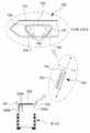
도 1은 종래 콤바인의 측면도, 도 2는 종래 콤바인 작동상태의 측단면도이다.Figure 1 is a side view of a conventional combine, Figure 2 is a side cross-sectional view of the conventional combine operation state.
도시된 바와 같이, 종래의 콤바인은, 콩대를 세우고 수집하기 위하여 다수개의 수직대(11a)가 일정 간격을 두고 배열되어 있는 회전형태의 릴(reel)(11)과, 릴(11)에 의해 세워진 콩대를 절단하기 위한 절단날(12)과, 절단날(12)에 의해 베어진 콩대를 이송부(20)쪽으로 수집하여 컨베이어장치(21)에 넣어주는 나선 형태의 가이드부(13a)를 갖는 원통형의 이송스크류(13)로 이루어진 예취부(10)와, 예취부(10)를 통하여 베어진 콩대를 가이드하여 탈곡기능을 갖는 탈곡부(30)로 이송시키는 컨베이어장치(21) 형태의 이송부(20)와, 이송부(20)를 통해 이송된, 베어진 콩대가 콩알 및 껍질과 줄기로 선별되도록 하는 다수개의 탈곡드럼부 및 탈곡된 콩알을 낙하 분리시키 위한 탈곡망(35)으로 이루어진 탈곡부(30)를 포함하는 구성이 공지되어 있다.As shown, the conventional combine is built by a
그러나 종래의 콤바인에 있어서의 절단날을 포함하는 예취장치는, 밭작물의 줄기부 및 이삭부 모두를 예취하여 탈곡부로 이송하고 있어, 탈곡부에 투입되는 다량의 줄기부에 의하여 탈곡의 효율이 저하되는 문제점이 있었다.However, in the conventional combine harvesting apparatus including a cutting blade, both the stem part and the ear part of the field crop are mowed and transferred to the threshing part, so that the efficiency of threshing is lowered by the large amount of stem parts injected into the threshing part. There was a problem.
본 발명은 상기의 문제점을 해결하기 위한 것으로서, 제1 예취칼날장치의 칼날 높이를 작물이나 환경에 따라 자유롭게 조절하고, 밭에 남아 있는 줄기를 제2 예취칼날장치로 절단함으로서, 종래에 콤바인 예취부에서 예취 높이를 상향할 경우 밭에 잔존하는 줄기를 제거하기 위하여 쟁기작업 등의 또 다른 밭작업이 필요하게 되는 것을 원천적으로 차단할 수 있는 이중 예취 칼날 장치를 제공하고자 함이다.The present invention is to solve the above problem, by freely adjusting the height of the blade of the first mowing blade device according to the crop or environment, and cutting the stem remaining in the field with the second mowing blade device, in the related art It is intended to provide a dual mowing blade device that can fundamentally block the necessity of another field work such as plowing in order to remove stems remaining in the field when the mowing height is increased.
본 발명 이중 예취 칼날 장치는, 콤바인에 구비된 제1 예취칼날장치, 제1 예취칼날장치의 후방에 설치되고, 그 높이는 제1 예취칼날장치보다 아래에 설치되는 제2 예취칼날장치가 구비되되; 제2 예취칼날장치는, 콤바인의 몸체에 구비된 구동축에 축결합되며, 외표면 일측에 회전이 가능한 회동부가 구비된 타원캠판과, 일측은 회동부와 연결되고, 타측은 요동레버와 회전이 가능하게 결합된 연결바와, 일부분이 절개된 초승달 원판형상이며, 상측에 형성된 상부힌지축은 연결바의 타측과 회전이 가능한 상태로 결합되며, 측면에 형성된 측면힌지축은, 지지프레임의 외면에 돌출된 상태로 구비된 지지대에 회전이 가능하도록 결합되고, 하면에 형성된 하부힌지축은 상부예취대와 회전이 가능하도록 결합된 요동레버와, 상부예취대 및 하부예취대에 결합된 예취칼날과, 길이가 긴 바 형상이며, 일측은 몸체에 회전이 가능하도록 결합되고, 타측은 베이스에 고정된 지지프레임과, 지지프레임을 횡방향으로 연결하는 보강프레임과, 일측은 몸체에 결합되고, 타측은 베이스에 결합되어, 제2 예취칼날장치의 높,낮이를 조절하는 유압실린더와, 몸체의 저면에 구비된 센서를 포함하는 것을 특징으로 한다.In the present invention, the dual mowing blade device is provided with a first mowing blade device provided in a combine, a second mowing blade device installed at the rear of the first mowing blade device, and having a height lower than the first mowing blade device; The second mowing blade device is axially coupled to a drive shaft provided in the body of the combine, and an elliptical cam plate having a rotating part capable of rotating on one side of the outer surface, one side connected to a rotating part, and the other side capable of rotating with a swing lever. The connecting bar is connected to each other in a crescent-shaped disk shape partially cut off, and the upper hinge axis formed on the upper side is coupled to the other side of the connecting bar in a rotatable state, and the side hinge axis formed on the side is in a state protruding from the outer surface of the support frame. It is coupled to the provided support so as to be rotatable, and the lower hinge shaft formed on the lower surface has a swing lever coupled to the upper mowing table and rotatable, the mowing blade combined with the upper mowing table and the lower mowing table, and a long bar shape One side is coupled to the body so as to be rotatable, the other side is a support frame fixed to the base, a reinforcing frame connecting the support frame in the transverse direction, and one side is coupled to the body, and the other side is coupled to the base. 2 It characterized in that it comprises a hydraulic cylinder that adjusts the height and height of the cutting blade device, and a sensor provided on the bottom of the body.
또한, 센서는, 예취칼날과 지면 사이의 거리를 측정하며, 측정된 신호는 제어부로 송신되고, 제어부는 수신된 신호가, 기 설정되어 내장된 작물절단 높이와 비교하여, 예취칼날과 지면 사이의 거리가 높으면, 유압실린더를 제어하여 예취칼날과 지면 사이의 거리를 좁힘으로써, 작물의 줄기가 지면으로부터 최소한으로 돌출된 높이에서 절단되도록 하는 것을 특징으로 한다.In addition, the sensor measures the distance between the mowing blade and the ground, and the measured signal is transmitted to the control unit, and the control unit compares the received signal with the preset and built-in crop cutting height, When the distance is high, by controlling the hydraulic cylinder to narrow the distance between the mowing blade and the ground, the stem of the crop is cut at a minimum protruding height from the ground.
또한, 예취칼날은, 길이가 긴 판재의 형상이고, 베이스의 상면에 고정되며, 상면에는 하부칼날이 결합된 하부예취대와, 길이가 긴 판재의 형상이며, 하면에는 상부칼날이 결합된 상부예취대를 포함하며, 하부칼날과 상부칼날은 면접촉하는 것을 특징으로 한다.In addition, the cutting blade is in the shape of a long plate, fixed to the upper surface of the base, and a lower cutting table with a lower blade attached to the upper surface, and an upper cutting board with a long plate material, and an upper cutting edge with an upper blade at the lower surface. It includes a stand, characterized in that the lower blade and the upper blade are in surface contact.
또한, 스페이서가 더 구비되되; 스페이서는, 보디의 일측면에 절개된 'ㄴ'자 형상으로 구비되어 베이스의 끝단부가 삽입되는 단턱과, 보디의 상단부에 함몰된 형상으로 구비되어 상,하부 칼날이 삽입되는 절개홈과, 보디의 상면에 지면과 수평한 형상으로 구비된 상부수평면과, 보디의 하면에 지면과 일정한 경사를 가지는 형상으로 구비된 하부경사면을 포함하는 것을 특징으로 한다.In addition, a spacer is further provided; The spacer is provided in a'b' shape cut on one side of the body and a stepped jaw into which the end of the base is inserted, a cut-out groove in which the upper and lower blades are inserted and the upper and lower blades are inserted into the upper end of the body. It is characterized in that it comprises an upper horizontal surface provided in a shape horizontal to the ground on the upper surface, and a lower inclined surface provided in a shape having a constant inclination with the ground on the lower surface of the body.
또한, 스페이서에는 탈착수단이 구비되되; 탈착수단은, 스페이서의 보디 상면에 원기둥 또는 사각기둥의 형상으로 돌출되어, 베이스에 형성된 결합통공에 끼움, 결합되는 지주와, 지주의 양측면에 일정한 경사각도를 가지면서 구비된 탄성날개편과, 탄성날개편의 외표면에 돌출된 구조로 구비되어, 베이스의 결합통공 내면에 형성된 걸림턱에 걸려 스페이서를 베이스에 고정하는 결합돌기와, 탄성날개편의 외측에 수평방향으로 절곡된 파지부와, 탄성날개편과 지주가 맞나는 지점에 원호의 함몰된 형상으로 구비된 응력집중방지홈을 포함하는 것을 특징으로 한다.In addition, the spacer is provided with a detachable means; The detachable means includes a pillar protruding in the shape of a cylinder or a square pillar on the upper surface of the body of the spacer and being inserted into and coupled to a coupling hole formed in the base, an elastic blade piece provided with a certain inclination angle on both sides of the pillar, and elasticity. It is provided in a structure protruding from the outer surface of the blade piece, the engaging protrusion that is hooked on the locking jaw formed in the inner surface of the coupling hole of the base to fix the spacer to the base, the gripping portion bent in the horizontal direction on the outside of the elastic blade piece, and the elastic blade piece It characterized in that it comprises a stress concentration prevention groove provided in a concave shape of a circular arc at the point where the support fits.
또한, 가압대가 더 구비되되; 가압대는, 내부에 중공부가 형성된 하우징과, 'ㄱ'자 형상이며, 상부칼날를 압박하는 압박부와, 압박부의 일측 끝단에 구비되어, 상부칼날과의 마찰저항을 최소화하는 면압베어링과, 하우징의 내측에 구비되며, 하우징을 관통하여, 압박부의 타측에 돌출된 형상으로 고정된 지지판과, 지지판의 하면과 하우징의 저면 사이에 구비된 탄성체와, 지지판의 상면에 접촉된 판재의 형상이며, 상면에는 가압홈이 구비된 가압판과, 하우징의 상면을 관통하여 나사,결합되며, 나사부의 끝단은 가압판의 가압홈에 접촉된 구조로 구비된 가압볼트를 포함하는 것을 특징으로 한다.In addition, a pressurizing table is further provided; The pressurizing table includes a housing with a hollow portion formed therein, a'b' shape, a pressurizing part that presses the upper blade, a surface pressure bearing that is provided at one end of the pressurizing part, and minimizes frictional resistance with the upper blade, and the inner side of the housing. The support plate is provided in the housing and is fixed in a shape protruding to the other side of the pressing unit, an elastic body provided between the lower surface of the support plate and the lower surface of the housing, and a plate material in contact with the upper surface of the support plate, and pressurized on the upper surface. It is characterized in that it includes a pressing plate having a groove, and a pressing bolt that is screwed and coupled through the upper surface of the housing, and an end of the threaded portion is provided in a structure in contact with the pressing groove of the pressing plate.
본 발명은 예취 칼날의 높이를 작물이나 환경에 따라 자유롭게 조절할 수 있으므로, 탈곡부 투입되는 줄기부의 양을 최소화하는 효과가 있다.In the present invention, since the height of the cutting blade can be freely adjusted according to the crop or environment, there is an effect of minimizing the amount of the stem portion to be introduced into the threshing portion.
또한, 밭에 남아 있어 잔존하는 줄기를 제2 예취 칼날장치로 절단함으로서, 쟁기작업 등의 또 다른 밭작업이 필요하게 되는 것을 원천적으로 방지할 수 있는 효과가 있다.In addition, by cutting the stems remaining in the field with the second mowing blade device, there is an effect of preventing the necessity of another field work such as plowing.
도 1은 종래 콤바인의 측면도.
도 2는 종래 콤바인 작동상태의 측단면도.
도 3은 콤바인에 본 발명 제1,2 예취 칼날장치가 설치된 상태의 사시도.
도 4는 제2 예취 칼날장치의 확대사시도.
도 5는 제2 예취 칼날장치의 부분 분해 사시도.
도 6은 요동레버의 확대 사시도.
도 7은 예취칼날의 확대 사시도.
도 8은 예취칼날의 측단면도.
도 9는 스페이서에 탈착수단이 구비된 상태의 측면도 및 부분확대도.
도 10은 스페이서의 탈착수단이 베이스의 결합통공에 결합된 상태의 단면도.
도 11은 가압대의 부분단면도.
도 12는 지지프레임에 구비된 가이드수단의 부분 확대사시도 및 X-X 축 단면도.1 is a side view of a conventional combine.
Figure 2 is a side cross-sectional view of the conventional combine operating state.
Figure 3 is a perspective view of a state in which the first and second mowing blade devices of the present invention are installed in the combine.
Figure 4 is an enlarged perspective view of a second cutting blade device.
5 is a partial exploded perspective view of a second cutting blade device.
6 is an enlarged perspective view of the swing lever.
7 is an enlarged perspective view of a cutting blade.
Figure 8 is a side cross-sectional view of the cutting blade.
9 is a side view and a partially enlarged view of a state in which the spacer is provided with a detachment means.
Figure 10 is a cross-sectional view of a state in which the detachment means of the spacer is coupled to the coupling hole of the base.
11 is a partial cross-sectional view of the pressurizing table.
12 is a partial enlarged perspective view and a cross-sectional view of the XX axis of the guide means provided on the support frame.
본 발명의 바람직한 실시 예를 첨부된 도면을 참조하여 상세히 설명한다. 참고로, 본 발명을 설명하는데 참조하는 도면에 도시된 구성요소의 크기, 선의 두께 등은 이해의 편의상 다소 과장되게 표현되어 있을 수 있다.A preferred embodiment of the present invention will be described in detail with reference to the accompanying drawings. For reference, the size of the components, the thickness of the line, and the like shown in the drawings referred to in describing the present invention may be somewhat exaggerated for convenience of understanding.
또, 본 발명의 설명에 사용되는 용어들은 본 발명에서의 기능을 고려하여 정의한 것이므로 사용자, 운용자 의도, 관례 등에 따라 달라질 수 있다. 따라서, 이 용어에 대한 정의는 본 명세서의 전반에 걸친 내용을 토대로 내리는 것이 마땅하다.In addition, terms used in the description of the present invention are defined in consideration of functions in the present invention, and thus may vary according to user, operator intention, custom, and the like. Therefore, it is appropriate to make the definition of this term based on the overall contents of the present specification.
그리고 본 출원에서, '포함하다', '가지다' 등의 용어는 명세서 상에 기재된 특정의 숫자, 단계, 동작, 구성요소, 부품 또는 이들을 조합한 것이 존재함을 지칭하는 것이지, 하나 또는 그 이상의 다른 특징이나 숫자, 단계, 동작, 구성요소, 부품 또는 이들을 조합한 것들의 존재 또는 부가 가능성을 미리 배제하지 않는 것으로 이해되어야 한다.And in the present application, terms such as'include' and'have' refer to the existence of specific numbers, steps, actions, components, parts, or a combination thereof described in the specification. It is to be understood that the presence or addition of features, numbers, steps, actions, components, parts, or combinations thereof, does not preclude the possibility of preliminary exclusion.
또한, 본 발명은 이하에서 개시되는 실시 예에 한정되는 것이 아니라 서로 다른 다양한 형태로 구현될 것이며, 단지 본 실시 예는 본 발명의 개시가 완전하도록 하며, 통상의 지식을 가진 자에게 발명의 범주를 완전하게 알려주기 위해 제공되는 것이다.In addition, the present invention is not limited to the embodiments disclosed below, but will be implemented in a variety of different forms, only the present embodiment makes the disclosure of the present invention complete, and the scope of the invention is given to those of ordinary skill in the art. It is provided to be fully informed.
그러므로, 본 발명은 다양한 변경을 가할 수 있고 여러 가지 형태를 가질 수 있는바, 구현 예(態樣, aspect)(또는 실시 예)들을 명세서에 상세하게 설명하고자 한다. 그러나 이는 본 발명을 특정한 개시 형태에 대해 한정하려는 것이 아니며, 본 발명의 기술적 사상에 포함되는 모든 변경, 균등물 내지 대체물을 포함하는 것으로 이해되어야 하고, 본 명세서에서 사용한 단수의 표현은 문맥상 명백하게 다르게 뜻하지 않는 한, 복수의 표현을 포함한다.Therefore, in the present invention, various changes can be made and various forms can be obtained, and implementation examples (aspects) (or embodiments) will be described in detail in the specification. However, this is not intended to limit the present invention to a specific form of disclosure, and should be understood to include all changes, equivalents, or substitutes included in the technical idea of the present invention, and the expression of the singular number used in the present specification is clearly different from the context. Includes plural expressions unless they are meant to be.
다만, 본 발명을 설명함에 있어서, 주지 또는 공지된 기능 혹은 구성에 대한 구체적인 설명은 본 발명의 요지를 명료하게 하기 위하여 생략하기로 한다.However, in describing the present invention, detailed descriptions of known or known functions or configurations will be omitted in order to clarify the gist of the present invention.
이하에서 본 발명의 구체적인 실시 예를 도면을 참고하여 설명한다.Hereinafter, specific embodiments of the present invention will be described with reference to the drawings.
도 3은 콤바인에 본 발명 제1,2 예취 칼날장치가 설치된 상태의 사시도, 도 4는 제2 예취 칼날장치의 확대사시도, 도 5는 제2 예취 칼날장치의 부분 분해 사시도. 도 6은 요동레버의 확대 사시도이다.Figure 3 is a perspective view of a state in which the first and second mowing blade devices of the present invention are installed in the combine, Figure 4 is an enlarged perspective view of the second mowing blade device, and Figure 5 is a partial exploded perspective view of the second mowing blade device. 6 is an enlarged perspective view of the swing lever.
콤바인에 제1 예취칼날장치(100), 릴(200), 컨베이어장치(300), 탈곡부(400)가 구비된 것은 앞서 종래의 기술(도 1, 도 2 참조)에서 살펴본 바와 같이 콤바인에서는 일반적으로 상용되는 주지, 관용의 구성이며, 제1 예취칼날장치(100)의 높이를 유압실린더 또는 기어장치 등의 승강수단을 이용하여 높이를 조절하는 구성 또한 주지, 관용의 구성임은 물론이다.The first
따라서, 여기에서는 위와 같이 일반적으로 알려져 있는 종래 구성의 구체적인 설명은 생략하고, 본 발명의 특징이 되는 부분만을 설명한다Therefore, here, the detailed description of the conventional configuration generally known as above is omitted, and only parts that are features of the present invention will be described.
도시된 바와 같이 본 발명의 제2 예취칼날장치(500)는, 그 설치되는 위치를 특정하고 있다는 점에 특징이 있다.As shown, the second
즉, 제2 예취칼날장치(500)는, 제1 예취칼날장치(100)의 후방에 설치되고, 그 높이는 제1 예취칼날장치(100)보다 아래에 설치되는 것으로 위치가 특정되어 있는 것이다.That is, the second
이와 같이 제2 예취칼날장치(500)의 위치가 특정됨으로써, 우선적으로 제1 예취칼날장치(100)가 이삭을 포함하는 작물의 줄기 상단부를 절단한 후에, 제2 예취칼날장치(500)에 의하여 밭에 잔존하는 작물의 줄기 밑둥을 절단함으로써, 줄기가 탈곡부로 유입되는 것을 최소화하면서, 밭에 남아 있는 줄기를 제거하기 위한 쟁기작업 등의 또 다른 밭작업이 필요하게 되는 것을 원천적으로 방지할 수 있는 기능 및 작용, 효과를 가지게 된다.By specifying the position of the second
제2 예취칼날장치(500)의 구체적인 구성을 살펴보면,Looking at the specific configuration of the second
제2 예취칼날장치(500)는, 타원캠판(510), 연결바(520), 지지프레임(530a), 보강프레임(530b), 요동레버(540), 예취칼날(550), 유압실린더(580), 센서(S)를 포함하고 있다.The second
타원캠판(510)은, 콤바인의 몸체에 구비된 구동축에 축결합되어 있으며, 구동축이 회전하는 것과 연동하여 회전하며, 타원캠판(510)의 외표면 일측에는 회전이 가능한 회동부(510a)가 구비되어 있다.The
상기 구동축은 도시하지 않은 모터 등의 구동장치에 연결되어 있음은 물론이다.It goes without saying that the drive shaft is connected to a driving device such as a motor (not shown).
연결바(520)는, 일측은 회동부(510a)와 연결되어 있고, 타측은 후술하는 요동레버(540)와 회전이 가능하게 결합되어 있어, 회동부(510a)가 회전함에 따라 연결바(520)는 직선, 왕복운동을 한다.The connecting
요동레버(540)는, 일부분이 절개된 초승달 원판형상을 하고 있으며, 상측에는 상부힌지축(542a)이 형성되어 있어, 연결바(520)의 타측과 회전이 가능한 상태로 결합되며, 측면에는 측면힌지축(542b)이 형성되어 있어, 지지프레임(530a)의 외면에 돌출된 상태로 구비된 지지대(541)에 회전이 가능하도록 결합되고, 하면에는 하부힌지축(542c)이 형성되어 있어, 상부예취대(551)와 회전이 가능하도록 결합된다.The
예취칼날(550)은, 상부예취대(551) 등에 리벳, 볼트 등의 고정수단에 의하여 결합되어 있으며, 그 구체적인 구성은 후술한다.The
지지프레임(530a)은, 길이가 긴 바 형상을 하고 있으며, 일측은 몸체에 회전이 가능하도록 결합하고, 타측은 후술하는 베이스(554)에 고정된다.The
보강프레임(530b)은, 지지프레임(530a)을 보강하기 위한 것으로, 각각의 지지프레임(530a)을 횡방향으로 연결한다.The reinforcing
유압실린더(580)는, 일측은 몸체에 결합되어 있고, 타측은 베이스(554)에 결합되어 있어, 유압실린더(580)가 출몰하는 것에 의하여, 지지프레임(530a)이 회전되고, 지지프레임(530a)이 회전됨으로써, 예취칼날(550)을 포함하는 제2 예취칼날장치(500)의 높,낮이를 조절할 수 있는 것이다.
센서(S)는, 몸체의 저면에 구비되어, 예취칼날(550)과 지면 사이의 거리를 측정하며, 센서에서 측정된 신호는 제어부(도시를 생략함)로 송신되고, 제어부는 수신된 신호가, 기 설정되어 내장된 작물절단 높이와 비교하여, 예취칼날(550)과 지면 사이의 거리가 높으면, 유압실린더(580)를 제어하여 예취칼날(550)과 지면 사이의 거리를 좁힘으로써, 작물의 줄기가 지면으로부터 최소한으로 돌출된 높이에서 절단되도록 한다.The sensor (S) is provided on the bottom of the body and measures the distance between the
이와 같은 제2 예취칼날장치(500)의 작동관계를 살펴보면,Looking at the operating relationship of such a second
콤바인이 밭 등의 작업장으로 진입하면, 몸체의 저면에 구비된 센서(S)가 예취칼날(550)과 지면 사이의 거리를 측정하고, 그 측정된 신호와 연동하여 제어부는 유압실린더(580)의 출몰길이를 제어함으로써, 제2 예취칼날장치(500)의 예취칼날(550)이 지면과 작물절단에 필요한 최소한의 높이를 가지도록 한다.When the combine enters a work place such as a field, a sensor (S) provided on the bottom of the body measures the distance between the
그 다음 구동축을 구동하면, 구동축과 연결된 타원캠판(510)이 회전하고, 타원캠판의 외면에 구비된 회동부(510a)와 연결된 연결바(520)가 직선, 왕복운동을 하게 된다.Then, when the drive shaft is driven, the
연결바(520)가 직선, 왕복운동을 하면, 연결바(520)의 타측에 회동가능하게 연결된 요동레버(540)가, 상부힌지축(542a), 측면힌지축(542b), 하부힌지축(542c)과 연동하여, 좌,우 방향으로 요동한다.When the connecting
요동레버(540)가 좌,우 방향으로 요동하면, 요동레버(540)와 연결된 상부예취대(551)가 좌,우 방향으로 요동하게 되고, 상부예취대(551)에 결합된 예취칼날(550)에 의하여 작물 줄기의 밑둥이 절단되는 것이다.When the
이하의 실시 예에서는 예취칼날의 구체적 구성에 관하여 설명한다.In the following embodiments will be described with respect to the specific configuration of the cutting blade.
도 7은 예취칼날의 확대 사시도, 도 8은 예취칼날의 측단면도이다.Figure 7 is an enlarged perspective view of the cutting blade, Figure 8 is a side cross-sectional view of the cutting blade.
도시된 바와 같이 예취칼날(550)은, 상부예취대(551), 하부예취대(552), 상부칼날(553a), 하부칼날(553b)을 포함하고 있으며, 스페이서(560), 가압대(570)가 더 구비되어 있다.As shown, the
하부예취대(552)는, 길이가 긴 판재의 형상을 하고 있고, 베이스(554)의 상면에 고정되어 있으며, 하부예취대(552)의 상면에는 하부칼날(553b)이 리벳, 볼트, 스폿용접 등의 고정수단으로 결합되어 있다.The lower cutting table 552 has a shape of a long plate, and is fixed to the upper surface of the
상부예취대(551)는, 길이가 긴 판재의 형상을 하고 있으며, 하면에는 상부칼날(553a)이 리벳, 볼트, 스폿용접 등의 고정수단으로 결합되어 있으며, 상부예취대(551)의 일측은 하부힌지축(542c)을 매개로 요동레버(540)와 결합된다.The upper cutting table 551 has a shape of a long plate, and on the lower surface, the
상기 하부칼날(553b) 및 상부칼날(553a)은 면접촉을 하고 있다.The
즉, 고정된 삼각형상의 하부칼날(553b)과 접촉된 삼각형상의 상부칼날(553a)은, 요동레버(540)와 연동하는 상부예취대(551)의 하면에 고정되어, 좌,우 방향의 요동운동 상태로 접촉되는 것이므로, 고정된 상부칼날(553a) 및 요동하는 하부칼날(553b)의 면접촉에 의하여 작물의 줄기는 가위로 절단하는 것과 같은 기능을 가지는 것이다.That is, the triangular
가압대(570)는, 'ㄷ'자 형상을 가지고 있으며, 일측은 베이스(554)의 상면에 볼트로 고정되고, 타측에 형성된 압박부(571)는 상부칼날(553a)의 상면을 가압하여 절단 효율을 극대화 한다.The pressing table 570 has a'C' shape, and one side is fixed with bolts to the upper surface of the
상기 압박부(571)의 끝단면에는 면압베어링(572)이 구비되어 있어, 좌,우로 요동하는 상부칼날(553a)의 상면과 접촉을 할 때, 슬라이딩이 원활하게 이루지게 하면서, 상부칼날(553a)이 마모되는 것을 방지하는 기능을 가진다.A surface pressure bearing 572 is provided at the end surface of the
위 면압베어링(572)은, 구리 100 중량부에 대하여, 철 10 ~ 20 중량부, 스테아르산 아연(Zinc Stearate Zn) 3 ~ 5 중량부, 흑연 0.2 ~ 5.5 중량부, 이황화몰리브덴 0.1 ~ 9.0 중량부, 주석 4 ~ 10 중량부, 니켈 7 ~ 10 중량부, 망간 1 ~ 4 중량부를 포함하는 조성물로 이루어진 것을 특징으로 한다.The upper surface pressure bearing 572 is based on 100 parts by weight of copper, 10 to 20 parts by weight of iron, 3 to 5 parts by weight of zinc stearate, 0.2 to 5.5 parts by weight of graphite, 0.1 to 9.0 parts by weight of molybdenum disulfide , Tin 4 to 10 parts by weight, nickel 7 to 10 parts by weight, characterized in that consisting of a composition comprising 1 to 4 parts by weight of manganese.
이러한 조성물로 이루어진 면압베어링은, 충격하중에 강하고, 균열저지효과 및 피로한도가 극히 우수하며, 상부칼날에 대하여 늘어붙음(seizure)이나 소착현상이 일어나지 않으면서, 마찰저항이 최소화되는 효과가 있다.A surface pressure bearing made of such a composition is strong against impact load, has extremely excellent crack arresting effect and fatigue limit, and does not cause seizure or seizure with respect to the upper blade, and has the effect of minimizing frictional resistance.
스페이서(560)는, 얇은 판재의 형상을 하고 있으며, 베이스(554)의 저면에 고정되고, 절개홈(561), 상부수평면(562), 하부경사면(563), 단턱(564)으로 이루어져 있다.The
위와 같은 스페이서(560)는 베이스의 저면에 용접 등의 고정수단으로 고정될 수 있음은 물론이다.It goes without saying that the
상기 단턱(564)은, 보디의 일측면에 절개된 'ㄴ'자 형상으로 구비되어 베이스(554)의 끝단부가 삽입된다.The stepped
상기 절개홈(561)은, 보디의 상단부에 함몰된 형상으로 구비되어 상,하부 칼날(553a)(553b)이 비접촉 상태로 삽입된다.The
상기 상부수평면(562)은, 보디의 상면에 지면과 수평한 형상으로 구비된다.The upper
상기 하부경사면(563)은, 보디의 하면에 지면과 일정한 경사를 가지는 형상으로 구비된다.The lower
위와 같은 스페이서는(560), 작물의 줄기를 하부칼날(553b) 및 상부칼날(553a) 측으로 가이드 함으로써, 절단효율을 극대화하면서, 상,하부 칼날(553a)(553b)이 지면 또는 돌에 부딪히는 것을 방지하는 한편, 흙을 베는 것을 방지함에 따라 상,하부 칼날의 파손과 마모를 방지하여 내구성을 높이는 기능 및 작용, 효과가 있다.
이하에서는 스페이서의 탈착구조에 관한 또 다른 실시 예에 관하여 설명한다.Hereinafter, another embodiment of the detachable structure of the spacer will be described.
스페이서는 지면과의 접촉이 빈번하게 일어나고, 작물 줄기와의 접촉이 지속적으로 이루어지므로, 마모 또는 파손되는 경우가 다반사이다.Since the spacer is frequently in contact with the ground and is constantly in contact with the crop stem, it is often worn or damaged.
따라서 수리, 보수 및 교체를 용이하게 하기 위하여 스페이서를 베이스로부터 손쉽게 착탈할 필요가 있으므로, 본 실시 예서는 스페이서의 용이한 착탈구조를 제시하고 있다.Therefore, since it is necessary to easily attach and detach the spacer from the base in order to facilitate repair, maintenance, and replacement, the present embodiment proposes an easy detachable structure of the spacer.
도 9는 스페이서에 탈착수단이 구비된 상태의 측면도 및 부분확대도, 도 10은 스페이서의 탈착수단이 베이스의 결합통공에 결합된 상태의 단면도이다.9 is a side view and a partially enlarged view of a state in which the spacer is equipped with a detachment means, and FIG. 10 is a cross-sectional view of a state in which the detachment means of the spacer is coupled to the coupling hole of the base.
도시된 바와 같이 스페이서(560)의 보디 상면에는 탈착수단(600)이 다수개 구비되어 있고, 그 탈착수단(600)은, 지주(610), 탄성날개편(620), 결합돌기(630), 파지부(640), 응력집중방지홈(650)을 포함하고 있다.As shown, a plurality of detachment means 600 are provided on the upper surface of the body of the
지주(610)는, 스페이서의 보디 상면에 원기둥 또는 사각기둥의 형상으로 돌출되어 있어, 베이스(554)에 형성된 결합통공에 끼움, 결합된다.The
탄성날개편(620)은, 지주(610)의 양측면에 일정한 경사각도를 가지면서 구비되어 있으며, 탄성재질로 형성되어 있다.The
결합돌기(630)는, 탄성날개편(620)의 외표면에 돌출된 구조로 구비되어, 베이스(554)의 결합통공 내면에 형성된 걸림턱에 걸려 스페이서를 베이스에 고정하는 기능을 가진다.The
파지부(640)는, 탄성날개편(620)의 외측에 수평방향으로 절곡된 구조를 가지고 있어, 사용자가 파지하여 가압할 수 있는 기능을 가진다.The
응력집중방지홈(650)은, 탄성날개편(620)과 지주(610)가 맞나는 지점에 원호의 함몰된 형상으로 구비되며, 탄성날개편(620)의 반복적 탄성변형에 의하여 응력이 집중되어 파손되는 것을 방지한다.The stress
이와 같은 스페이서 탈착수단의 작동관계를 살펴보면,Looking at the operating relationship of the spacer detachment means,
사용자가 탈착수단(600)의 파지부(640)를 압박하면, 탄성날개편(620)은 탄성변형을 일으켜, 지주(610)방향으로 밀착되는 형상으로 변형된다.When the user presses the gripping
이러한 상태에서 탈착수단을 베이스(554)의 결합통공에 삽입한 후, 압박을 해제하면, 탄성날개편이 탄성력에 의하여 복원되면서, 탄성날개편의 외면에 형성된 걸림돌기(630)가, 결합통공의 내면에 형성된 걸림턱에 걸려 고정되는 것이므로, 스페이서를 베이스에 고정할 수 있는 것이다.In this state, when the detachment means is inserted into the coupling hole of the
콤바인의 지속적인 작업으로 스페이서(560)가 파손 또는 마모되어 수리, 보수 또는 교체의 필요성이 있을 때는, 사용자가 파지부를 압박하면, 탄성날개편은 탄성변형을 일으켜, 지주방향으로 밀착되는 형상으로 변형되는 것이므로, 결합통공으로부터 스페이서를 손 쉽게 분리할 수 있는 것이다.When the
이하 실시 예에서는 가압대의 구체적 구조에 관하여 설명한다.In the following embodiments, a specific structure of the pressurizing table will be described.
도 11은 가압대의 부분단면도이다.11 is a partial cross-sectional view of the pressurizing table.
도시된 바와 같이 가압대(570)는, 압박부(571), 면압베어링(572), 지지판(573), 하우징(574), 가압판(575), 가압볼트(576), 탄성체(577)를 포함하고 있다.As shown, the pressing table 570 includes a
하우징(574)은, 내부에 중공부가 형성되어 있어, 가압에 필요한 부품이 내장되어 있다.The
압박부(571)는, 'ㄱ'자 형상을 하고 있으며, 상부칼날(553a)를 압박하여 절단 효율을 극대화한다.The
면압베어링(572)은, 압박부(571)의 일측 끝단에 구비되어 있어, 상부칼날(553a)과의 마찰저항을 최소화한다.The surface pressure bearing 572 is provided at one end of the
지지판(573)은, 하우징(574)의 내측에 구비되며, 하우징(574)을 관통하여, 압박부(571)의 타측에 돌출된 형상으로 고정된다.The
탄성체(577)는, 지지판(573)의 하면과 하우징(574)의 저면 사이에 구비되어 있고, 상기 탄성체는 코일스프링, 판스프링, 고무스프링 등으로 형성될 수 있으며, 콤바인의 구동 중에 발생하는 진동을 흡수하여 상쇄시키는 기능을 가진다.The
가압판(575)은, 지지판(572)의 상면에 접촉된 판재의 형상이며, 가압판(575)의 상면에는 가압홈(575a)이 구비되어 있다.The
상기 가압판(575)은 가압볼트(576)로부터 가해지는 집중압력을 가압판의 전체면적으로 분산시킨 상태로 지지판을 가압시키는 것이므로, 지지판이 가압볼트의 집중압력에 의하여 파손되는 것을 방지하는 작용, 효과를 가진다.Since the
가압판이 파손되면, 가압판을 교체하는 것만으로, 지지판이 파손되는 것을 차단할 수 있는 것이다.When the pressure plate is damaged, it is possible to prevent the support plate from being damaged by simply replacing the pressure plate.
가압볼트(576)는, 하우징(574)의 상면을 관통하여 나사,결합되어 있으며, 나사부의 끝단은 가압판(575)의 가압홈(575a)에 접촉된 구조로 구비된다.The
이와 같은 가압대의 작동관계를 살펴보면,Looking at the operating relationship of such a pressurizer,
상부칼날(553a)을 가압하는 압력을 조절하기 위하여, 사용자가 가압볼트(576)를 회전시키면, 가압볼트는 하강하면서, 가압볼트가 접촉된 가압홈(575a)에서 미끄럼접촉하면서, 가압판(575)을 하강시킨다. 가압판이 하강하면, 가압판과 면접촉된 지지판(573)이 하강하면서 탄성체(577)를 압축시켜, 탄성력이 부여된 상태를 유지함으로써, 가압대(570)에 전달되는 진동을 흡수하여 감쇄한다.In order to adjust the pressure to press the
지지판(573)이 하강하면, 지지판과 연결되어 있는 압박부(571)가 하강하면서, 상부칼날(553a)을 가압하여, 작물의 절단효율을 극대화시킨다.When the
이하의 실시 예에서는 작물을 제2 예취칼날장치의 내측으로 안내하는 가이드수단에 관하여 설명한다.In the following embodiment, a guide means for guiding the crops to the inside of the second mowing blade device will be described.
콤바인의 제1 예취칼날장치로 절단한 후 작물의 줄기는 이삭부가 절단된 상태이므로, 줄기는 생육상태에 따라서 직립상태로 되어 있지 않고, 일정 방향으로 경사진 상태로 식립되어 있는 경우가 있으므로, 이러한 줄기의 절단효율을 높이기 위하여서는 제2 예취칼날장치의 내측으로 줄기를 안내하여 인입시키는 수단이 필요한데, 본 실시 예에서는 위와 같은 줄기를 제2 예취칼날장치의 내측으로 안내하는 가이드수단을 제시하고 있다.After cutting with the first mowing blade device of the combine, the stem of the crop is in a state where the ear is cut, so the stem is not in an upright state depending on the growing state, but is planted in a state that is inclined in a certain direction. In order to increase the cutting efficiency of the stem, a means for guiding the stem to the inside of the second mowing blade device and leading it in is necessary.In this embodiment, a guide means for guiding the stem to the inside of the second mowing blade device is provided. .
도 12는 지지프레임에 구비된 가이드수단의 부분 확대사시도 및 X-X 축 단면도이다.12 is a partial enlarged perspective view and an X-X sectional view of the guide means provided in the support frame.
도시된 바와 같이 가이드수단(700)은 콤바인 제2 예취칼날장치 외측에 구비된 지지프레임(530a)에 설치되어 있다.As shown, the guide means 700 is installed on the
위와 같은 가이드수단(700)은, 가이드몸체(710), 구동롤러(720), 종동롤러(730), 벨트(740), 안내편(750), 가이드롤러(760)을 포함하고 있다.The guide means 700 as described above includes a
가이드몸체(710)는, 내부에 중공부가 형성되고 일정한 두께를 가지는 박스형상을 하고 있으며, 지지프레임(530a)의 외측으로 경사진 구조로 설치되어 있고, 내측면에는 개방구가 구비되어 있다.The
즉, 가이드몸체(710)는 좌,우측 지지프레임(530a)에 양팔을 벌린 형상으로 설치되어 있어, 줄기를 경사진 가이드몸체의 안쪽으로 안내하는 기능을 가진다.That is, the
구동롤러(720)는, 가이드몸체(710)의 내부에 회전이 가능한 상태로 구비되어 있으며, 도시하지 않은 모터 등의 동력수단에 연결되어 있어, 동력수단의 구동에 의하여 회전한다.The driving
종동롤러(730)는, 구동롤러(720)와 일정한 간격두고, 가이드몸체의 내부에 회전이 가능한 상태로 구비되어 있다.The driven
벨트(740)는, 구동롤러(720) 및 종동롤러(730)의 외면에 감겨있어, 구동롤러의 회전과 연동하여 구동롤러와 종동롤러 사이를 이동한다.The
안내편(750)은, 벨트(740)의 외면에 돌출된 형상으로 구비되며, 상기 안내편은 가이드몸체의 내면에 형성된 개방구의 외부로 돌출되어 있다.The
가이드롤러(760)는, 구동롤러(720)와 종동롤러(730) 사이에 구비되어 있으며, 구동롤러(720)와 종동롤러(730)을 연결하는 가상의 축선을 기준으로 개방구 방향을 향하여 아래쪽에 구비되어 있어, 가이드롤러(760)를 경유하는 벨트(740)를 개방구와 근접하게 안내함으로서, 벨트(740)의 외면에 구비된 안내편(750)이 개방구의 외면에 돌출된 상태로 이동하게 되어, 줄기를 안내하는 기능을 가지게 한다.The
이와 같은 가이드수단(700)의 작동관계를 살펴보면,Looking at the operating relationship of such a guide means 700,
콤바인이 작동하기 시작하면, 사용자는 동력수단을 작동시켜, 구동롤러(720)를 회전시킨다.When the combine starts to operate, the user operates the power means to rotate the
구동롤러가 회전하면, 벨트(740)도 회전하면서, 벨트의 외면에 구비된 안내편(750)이 개방구의 외부로 돌출된 상태로 가이드몸체(710)의 내부를 향하여 이동하는 것이므로, 안내편에 접촉되는 작물의 줄기는 가이드몸체를 타고 내측으로 안내되어 제2 예취칼날장치로 유입되는 것이어서, 줄기 절단의 효율을 극대화할 수 있는 것이다.When the driving roller rotates, the
100:제1 예취칼날장치 200:휠
300:컨베이어 400:탈곡부
500:제2 예취칼날장치 510:타원캠판
510a:회동부 520:연결바
530a:지지프레임 530b:보강프레임
540:요동레버 541:지지대
542a:상부회전축 542b:측면회전축
542c:하부회전축 550:예취칼날
551:상부예취대 552:하부예취대
553a:상부칼날 553b:하부칼날
554:베이스 560:스페이서
561:절개홈 562:상부수평면
563:하부경사면 564:단턱
570:가압대 571:압박부
572:면압베어링 573:지지판
574:하우징 575:가압판
575a:가압홈 576:가압볼트
577:탄성체 580:유압실린더
600:탈착수단 610:지주
620:탄성날개편 630;걸림돌기
640:파지부 650:응력집중방지홈
700:가이드수단 710:가이드몸체
720;구동롤러 730:종동롤러
740:벨트 750;안내편
760:가이드롤러 S:센서100: first mowing blade device 200: wheel
300: conveyor 400: threshing part
500: second cutting blade device 510: oval cam plate
510a: rotating part 520: connecting bar
530a:
540: swing lever 541: support
542a:
542c: lower rotating shaft 550: cutting blade
551: upper cutting unit 552: lower cutting unit
553a:
554: base 560: spacer
561: incision groove 562: upper horizontal plane
563: lower slope 564: stepped
570: presser 571: presser
572: surface pressure bearing 573: support plate
574: housing 575: pressure plate
575a: pressure groove 576: pressure bolt
577: elastic body 580: hydraulic cylinder
600: detachment means 610: holding
620:
640: gripping part 650: stress concentration prevention groove
700: guide means 710: guide body
720; driving roller 730: driven roller
740:
760: guide roller S: sensor
Claims (6)
Translated fromKorean제1 예취칼날장치(100)의 후방에 설치되고, 그 높이는 제1 예취칼날장치(100)보다 아래에 설치되는 제2 예취칼날장치(500)가 구비되되;
제2 예취칼날장치(500)는,
콤바인의 몸체에 구비된 구동축에 축결합되며, 외표면 일측에 회전이 가능한 회동부(510a)가 구비된 타원캠판(510)과,
일측은 회동부(510a)와 연결되고, 타측은 요동레버(540)와 회전이 가능하게 결합된 연결바(520)와,
일부분이 절개된 초승달 원판형상이며, 상측에 형성된 상부힌지축(542a)은 연결바(520)의 타측과 회전이 가능한 상태로 결합되며, 측면에 형성된 측면힌지축(542b)은, 지지프레임(530a)의 외면에 돌출된 상태로 구비된 지지대(541)에 회전이 가능하도록 결합되고, 하면에 형성된 하부힌지축(542c)은 상부예취대(551)와 회전이 가능하도록 결합된 요동레버(540)와,
상부예취대(551) 및 하부예취대(552)에 결합된 예취칼날(550)과,
길이가 긴 바 형상이며, 일측은 몸체에 회전이 가능하도록 결합되고, 타측은 베이스(554)에 고정된 지지프레임(530a)과,
지지프레임(530a)을 횡방향으로 연결하는 보강프레임(530b)과,
일측은 몸체에 결합되고, 타측은 베이스(554)에 결합되어, 제2 예취칼날장치(500)의 높,낮이를 조절하는 유압실린더(580)와,
몸체의 저면에 구비된 센서(S)를 포함하는 것을 특징으로 하는 이중 예취 칼날 장치.
The first mowing blade device 100 provided in the combine,
It is installed at the rear of the first mowing blade device 100, the height of which is provided with a second mowing blade device 500 installed below the first mowing blade device 100;
The second cutting blade device 500,
An elliptical cam plate 510 provided with a rotating part 510a capable of being axially coupled to a drive shaft provided on the body of the combine and rotatable on one side of the outer surface,
One side is connected to the rotating part (510a), the other side is connected to the swing lever 540 and the connection bar 520 rotatably coupled,
A portion of the crescent disk shape is cut, the upper hinge shaft (542a) formed on the upper side is coupled to the other side of the connection bar 520 in a rotatable state, and the side hinge shaft (542b) formed on the side is a support frame (530a) ) Is rotatably coupled to the support 541 provided in a protruding state on the outer surface of the), and the lower hinge shaft 542c formed on the lower surface is a swing lever 540 coupled to the upper mowing table 551 so as to be rotatable Wow,
The cutting blade 550 coupled to the upper cutting table 551 and the lower cutting table 552,
It has a long bar shape, and one side is coupled to the body so as to be rotatable, and the other side is a support frame 530a fixed to the base 554,
A reinforcing frame (530b) connecting the support frame (530a) in the transverse direction,
One side is coupled to the body, the other side is coupled to the base 554, a hydraulic cylinder 580 for adjusting the height and height of the second cutting blade device 500, and
Dual mowing blade device, characterized in that it comprises a sensor (S) provided on the bottom of the body.
센서(S)는,
예취칼날(550)과 지면 사이의 거리를 측정하며, 측정된 신호는 제어부로 송신되고, 제어부는 수신된 신호가, 기 설정되어 내장된 작물절단 높이와 비교하여, 예취칼날(550)과 지면 사이의 거리가 높으면, 유압실린더(580)를 제어하여 예취칼날(550)과 지면 사이의 거리를 좁힘으로써, 작물의 줄기가 지면으로부터 최소한으로 돌출된 높이에서 절단되도록 하는 것을 특징으로 하는 이중 예취 칼날 장치.
The method of claim 1,
The sensor S,
The distance between the cutting blade 550 and the ground is measured, and the measured signal is transmitted to the control unit, and the received signal is compared with the preset and built-in crop cutting height, and between the cutting blade 550 and the ground. When the distance of is high, by controlling the hydraulic cylinder 580 to narrow the distance between the mowing blade 550 and the ground, the stem of the crop is cut at a minimum protruding height from the ground. .
예취칼날(550)은,
길이가 긴 판재의 형상이고, 베이스(554)의 상면에 고정되며, 상면에는 하부칼날(553b)이 결합된 하부예취대(552)와,
길이가 긴 판재의 형상이며, 하면에는 상부칼날(553a)이 결합된 상부예취대(551)를 포함하며,
하부칼날(553b)과 상부칼날(553a)은 면접촉하는 것을 특징으로 하는 이중 예취 칼날 장치.
The method of claim 2,
The mowing blade (550),
It has a shape of a long plate and is fixed to the upper surface of the base 554, and a lower cutting table 552 to which a lower blade 553b is coupled to the upper surface,
It is a shape of a long plate, and includes an upper cutting table 551 to which an upper blade 553a is coupled on the lower surface,
The lower blade (553b) and the upper blade (553a) is a double mowing blade device, characterized in that the surface contact.
스페이서(560)가 더 구비되되;
스페이서(560)는,
보디의 일측면에 절개된 'ㄴ'자 형상으로 구비되어 베이스(554)의 끝단부가 삽입되는 단턱(564)과,
보디의 상단부에 함몰된 형상으로 구비되어 상,하부 칼날(553a)(553b)이 삽입되는 절개홈(561)과,
보디의 상면에 지면과 수평한 형상으로 구비된 상부수평면(562)과,
보디의 하면에 지면과 일정한 경사를 가지는 형상으로 구비된 하부경사면(563)을 포함하는 것을 특징으로 하는 이중 예취 칼날 장치.
The method of claim 3,
The spacer 560 is further provided;
The spacer 560,
A stepped jaw 564 in which the end of the base 554 is inserted by being provided in a'b' shape cut off on one side of the body,
An incision groove 561 in which the upper and lower blades 553a and 553b are inserted and provided in a recessed shape at the upper end of the body,
An upper horizontal surface 562 provided in a shape horizontal to the ground on the upper surface of the body,
Dual mowing blade device, characterized in that it comprises a lower inclined surface (563) provided in a shape having a constant inclination with the ground on the lower surface of the body.
스페이서(560)에는 탈착수단(600)이 구비되되;
탈착수단(600)은,
스페이서(560)의 보디 상면에 원기둥 또는 사각기둥의 형상으로 돌출되어, 베이스(554)에 형성된 결합통공에 끼움, 결합되는 지주(610)와,
지주(610)의 양측면에 일정한 경사각도를 가지면서 구비된 탄성날개편(620)과,
탄성날개편(620)의 외표면에 돌출된 구조로 구비되어, 베이스(554)의 결합통공 내면에 형성된 걸림턱에 걸려 스페이서를 베이스(554)에 고정하는 결합돌기(630)와,
탄성날개편(620)의 외측에 수평방향으로 절곡된 파지부(640)와,
탄성날개편(620)과 지주(610)가 맞나는 지점에 원호의 함몰된 형상으로 구비된 응력집중방지홈(650)을 포함하는 것을 특징으로 하는 이중 예취 칼날 장치.
The method of claim 4,
The spacer 560 is provided with a detachment means 600;
Desorption means 600,
A post 610 protruding from the upper surface of the body of the spacer 560 in the shape of a cylinder or a square pillar, and being inserted into and coupled to the coupling hole formed in the base 554,
Elastic blade pieces 620 provided while having a certain inclination angle on both sides of the holding 610,
A coupling protrusion 630 which is provided in a structure protruding from the outer surface of the elastic blade piece 620 and fixes the spacer to the base 554 by being caught by the locking jaw formed on the inner surface of the coupling hole of the base 554,
The gripping portion 640 bent in the horizontal direction on the outside of the elastic blade piece 620,
Double mowing blade device, characterized in that it comprises a stress concentration prevention groove 650 provided in a concave shape of an arc at the point where the elastic blade piece 620 and the post 610 meet.
가압대(570)가 더 구비되되;
가압대(570)는,
내부에 중공부가 형성된 하우징(574)과,
'ㄱ'자 형상이며, 상부칼날(553a)를 압박하는 압박부(571)와,
압박부(571)의 일측 끝단에 구비되어, 상부칼날(553a)과의 마찰저항을 최소화하는 면압베어링(572)과,
하우징(574)의 내측에 구비되며, 하우징(574)을 관통하여, 압박부(571)의 타측에 돌출된 형상으로 고정된 지지판(573)과,
지지판(573)의 하면과 하우징(574)의 저면 사이에 구비된 탄성체(577)와,
지지판(573)의 상면에 접촉된 판재의 형상이며, 상면에는 가압홈(575a)이 구비된 가압판(575)과,
하우징(574)의 상면을 관통하여 나사, 결합되며, 나사부의 끝단은 가압판(575)의 가압홈(575a)에 접촉된 구조로 구비된 가압볼트(576)를 포함하는 것을 특징으로 하는 이중 예취 칼날 장치.The method of claim 5,
The pressurizing table 570 is further provided;
The pressurizing table 570,
A housing 574 having a hollow portion formed therein,
It has a'a' shape, and a pressing part 571 that presses the upper blade 553a,
A surface pressure bearing 572 provided at one end of the pressing part 571 to minimize frictional resistance with the upper blade 553a,
A support plate 573 provided inside the housing 574, penetrating through the housing 574, and fixed in a protruding shape to the other side of the pressing portion 571,
An elastic body 577 provided between the lower surface of the support plate 573 and the lower surface of the housing 574,
The shape of a plate material in contact with the upper surface of the support plate 573, and a pressing plate 575 provided with a pressing groove 575a on the upper surface,
A double mowing blade, characterized in that it includes a pressing bolt 576 provided in a structure in contact with the pressing groove 575a of the pressing plate 575, which is screwed and coupled through the upper surface of the housing 574. Device.
Priority Applications (1)
| Application Number | Priority Date | Filing Date | Title |
|---|---|---|---|
| KR1020200131850AKR102224192B1 (en) | 2020-10-13 | 2020-10-13 | double blade device |
Applications Claiming Priority (1)
| Application Number | Priority Date | Filing Date | Title |
|---|---|---|---|
| KR1020200131850AKR102224192B1 (en) | 2020-10-13 | 2020-10-13 | double blade device |
Publications (1)
| Publication Number | Publication Date |
|---|---|
| KR102224192B1true KR102224192B1 (en) | 2021-03-10 |
Family
ID=75147833
Family Applications (1)
| Application Number | Title | Priority Date | Filing Date |
|---|---|---|---|
| KR1020200131850AActiveKR102224192B1 (en) | 2020-10-13 | 2020-10-13 | double blade device |
Country Status (1)
| Country | Link |
|---|---|
| KR (1) | KR102224192B1 (en) |
Cited By (1)
| Publication number | Priority date | Publication date | Assignee | Title |
|---|---|---|---|---|
| CN113532983A (en)* | 2021-06-24 | 2021-10-22 | 农业农村部南京农业机械化研究所 | Test bed for cutting and testing stalk crops |
Citations (5)
| Publication number | Priority date | Publication date | Assignee | Title |
|---|---|---|---|---|
| JPH07155044A (en)* | 1993-12-08 | 1995-06-20 | Yanmar Agricult Equip Co Ltd | Ordinary combine cutting device |
| KR100555631B1 (en) | 2003-12-03 | 2006-03-03 | 고경민 | Soybean Crop Harvester |
| KR200441804Y1 (en)* | 2007-07-11 | 2008-09-08 | 정대섭 | Mowing blade reinforcement device for combine |
| JP2013153655A (en)* | 2012-01-26 | 2013-08-15 | Yanmar Co Ltd | Combine harvester |
| KR20170002251A (en)* | 2015-06-29 | 2017-01-06 | 엘에스엠트론 주식회사 | Cutting Apparatus for Conventional Combine |
- 2020
- 2020-10-13KRKR1020200131850Apatent/KR102224192B1/enactiveActive
Patent Citations (5)
| Publication number | Priority date | Publication date | Assignee | Title |
|---|---|---|---|---|
| JPH07155044A (en)* | 1993-12-08 | 1995-06-20 | Yanmar Agricult Equip Co Ltd | Ordinary combine cutting device |
| KR100555631B1 (en) | 2003-12-03 | 2006-03-03 | 고경민 | Soybean Crop Harvester |
| KR200441804Y1 (en)* | 2007-07-11 | 2008-09-08 | 정대섭 | Mowing blade reinforcement device for combine |
| JP2013153655A (en)* | 2012-01-26 | 2013-08-15 | Yanmar Co Ltd | Combine harvester |
| KR20170002251A (en)* | 2015-06-29 | 2017-01-06 | 엘에스엠트론 주식회사 | Cutting Apparatus for Conventional Combine |
Cited By (2)
| Publication number | Priority date | Publication date | Assignee | Title |
|---|---|---|---|---|
| CN113532983A (en)* | 2021-06-24 | 2021-10-22 | 农业农村部南京农业机械化研究所 | Test bed for cutting and testing stalk crops |
| CN113532983B (en)* | 2021-06-24 | 2023-11-10 | 农业农村部南京农业机械化研究所 | A stem crop cutting test bench |
Similar Documents
| Publication | Publication Date | Title |
|---|---|---|
| US4989365A (en) | Machines for training plants | |
| CN110326426B (en) | An automated leafy vegetable harvesting line | |
| CN202218524U (en) | Combine harvester | |
| CN114830909B (en) | A profiling stem-cutting and seedling-rowing mechanism of a non-aligned garlic combine harvester | |
| CN103917085B (en) | Easy-to-use knife arm assembly for sickles | |
| CN101263761A (en) | combine harvester | |
| CA2133892C (en) | Combine harvester with secondary cutter | |
| KR102224192B1 (en) | double blade device | |
| US20110154793A1 (en) | Forage chopper header for harvesting both standing and down crop material | |
| US3545188A (en) | Impact mowing apparatus and system | |
| CN109168574B (en) | Combine harvester | |
| US3911651A (en) | Row crop harvesting device | |
| US4189906A (en) | Tomato harvester attachment | |
| US3698167A (en) | Blade mount for belt mower | |
| RU2565025C1 (en) | Header | |
| CN209449243U (en) | pea windrower | |
| GB1496752A (en) | Mowers | |
| CA2714719C (en) | Crop lifter with releasable tips | |
| KR20210037275A (en) | Driving type crop harvesting apparatus | |
| RU2267903C2 (en) | Apparatus for grinding of plant undergrowth and mechanism for joining to adapters | |
| US7231756B2 (en) | Device for mowing plants | |
| CN103997885B (en) | The self-regulation tool arm easily using and can be removed and head assembly for reaping hook | |
| CN222997061U (en) | Chain cutter cutting table and silage harvester | |
| CN216218799U (en) | Front mower of tractor | |
| JP3863899B2 (en) | Root crop harvesting machine |
Legal Events
| Date | Code | Title | Description |
|---|---|---|---|
| PA0109 | Patent application | Patent event code:PA01091R01D Comment text:Patent Application Patent event date:20201013 | |
| PA0201 | Request for examination | ||
| PA0302 | Request for accelerated examination | Patent event date:20201013 Patent event code:PA03022R01D Comment text:Request for Accelerated Examination | |
| PE0701 | Decision of registration | Patent event code:PE07011S01D Comment text:Decision to Grant Registration Patent event date:20201126 | |
| GRNT | Written decision to grant | ||
| PR0701 | Registration of establishment | Comment text:Registration of Establishment Patent event date:20210302 Patent event code:PR07011E01D | |
| PR1002 | Payment of registration fee | Payment date:20210303 End annual number:3 Start annual number:1 | |
| PG1601 | Publication of registration | ||
| PR1001 | Payment of annual fee | Payment date:20250219 Start annual number:5 End annual number:5 |