KR102216715B1 - Apparatus for controlling wide-band signal transmission gain in wireless communication systems and signal processing method of the same - Google Patents
Apparatus for controlling wide-band signal transmission gain in wireless communication systems and signal processing method of the sameDownload PDFInfo
- Publication number
- KR102216715B1 KR102216715B1KR1020150022363AKR20150022363AKR102216715B1KR 102216715 B1KR102216715 B1KR 102216715B1KR 1020150022363 AKR1020150022363 AKR 1020150022363AKR 20150022363 AKR20150022363 AKR 20150022363AKR 102216715 B1KR102216715 B1KR 102216715B1
- Authority
- KR
- South Korea
- Prior art keywords
- intermediate frequency
- digital
- baseband
- signals
- signal
- Prior art date
- Legal status (The legal status is an assumption and is not a legal conclusion. Google has not performed a legal analysis and makes no representation as to the accuracy of the status listed.)
- Active
Links
- 230000008054signal transmissionEffects0.000titleclaimsabstractdescription10
- 238000003672processing methodMethods0.000titleclaimsabstractdescription7
- 238000004891communicationMethods0.000titleabstractdescription8
- 230000005540biological transmissionEffects0.000claimsabstractdescription22
- 238000000034methodMethods0.000claimsdescription19
- 230000004044responseEffects0.000claimsdescription18
- 238000005070samplingMethods0.000claimsdescription12
- 230000002238attenuated effectEffects0.000claimsdescription11
- 238000010586diagramMethods0.000description7
- 238000012986modificationMethods0.000description2
- 230000004048modificationEffects0.000description2
- 238000007792additionMethods0.000description1
- 239000000835fiberSubstances0.000description1
- 230000006870functionEffects0.000description1
- 238000006467substitution reactionMethods0.000description1
Images


Classifications
- H—ELECTRICITY
- H04—ELECTRIC COMMUNICATION TECHNIQUE
- H04L—TRANSMISSION OF DIGITAL INFORMATION, e.g. TELEGRAPHIC COMMUNICATION
- H04L25/00—Baseband systems
- H04L25/02—Details ; arrangements for supplying electrical power along data transmission lines
- H04L25/10—Compensating for variations in line balance
- H—ELECTRICITY
- H04—ELECTRIC COMMUNICATION TECHNIQUE
- H04B—TRANSMISSION
- H04B1/00—Details of transmission systems, not covered by a single one of groups H04B3/00 - H04B13/00; Details of transmission systems not characterised by the medium used for transmission
- H04B1/02—Transmitters
- H04B1/04—Circuits
- H04B1/0475—Circuits with means for limiting noise, interference or distortion
- H—ELECTRICITY
- H04—ELECTRIC COMMUNICATION TECHNIQUE
- H04L—TRANSMISSION OF DIGITAL INFORMATION, e.g. TELEGRAPHIC COMMUNICATION
- H04L25/00—Baseband systems
- H04L25/02—Details ; arrangements for supplying electrical power along data transmission lines
- H04L25/0202—Channel estimation
- H04L25/022—Channel estimation of frequency response
- H—ELECTRICITY
- H04—ELECTRIC COMMUNICATION TECHNIQUE
- H04L—TRANSMISSION OF DIGITAL INFORMATION, e.g. TELEGRAPHIC COMMUNICATION
- H04L25/00—Baseband systems
- H04L25/02—Details ; arrangements for supplying electrical power along data transmission lines
- H04L25/0264—Arrangements for coupling to transmission lines
- H04L25/028—Arrangements specific to the transmitter end
- H—ELECTRICITY
- H04—ELECTRIC COMMUNICATION TECHNIQUE
- H04L—TRANSMISSION OF DIGITAL INFORMATION, e.g. TELEGRAPHIC COMMUNICATION
- H04L25/00—Baseband systems
- H04L25/02—Details ; arrangements for supplying electrical power along data transmission lines
- H04L25/08—Modifications for reducing interference; Modifications for reducing effects due to line faults ; Receiver end arrangements for detecting or overcoming line faults
- H—ELECTRICITY
- H04—ELECTRIC COMMUNICATION TECHNIQUE
- H04B—TRANSMISSION
- H04B1/00—Details of transmission systems, not covered by a single one of groups H04B3/00 - H04B13/00; Details of transmission systems not characterised by the medium used for transmission
- H04B1/02—Transmitters
- H04B1/04—Circuits
- H04B2001/0408—Circuits with power amplifiers
- H04B2001/0425—Circuits with power amplifiers with linearisation using predistortion
Landscapes
- Engineering & Computer Science (AREA)
- Computer Networks & Wireless Communication (AREA)
- Signal Processing (AREA)
- Power Engineering (AREA)
- Transmitters (AREA)
- Control Of Amplification And Gain Control (AREA)
Abstract
Translated fromKoreanDescription
Translated fromKorean본 발명은 무선통신시스템에서 광대역 신호의 송신이득을 조절하는 장치 및 그 신호 처리 방법에 관한 것으로 보다 상세하게는, 여러 개의 기저대역 디지털 신호들을 중간주파수(IF; Intermediate Frequency) 신호로 변환한 후 이를 다중화하여 동시에 송신할 수 있는 광대역 다중-중간주파수(multi-IF) 무선통신시스템의 송신 단에서 중간주파수 단위로 송신 이득을 달리 적용해주는 광대역 신호 송신이득 조절 장치 및 그 신호 처리 방법에 관한 것이다.The present invention relates to an apparatus for controlling the transmission gain of a broadband signal in a wireless communication system and a signal processing method thereof. More particularly, after converting a plurality of baseband digital signals into an intermediate frequency (IF) signal, The present invention relates to a broadband signal transmission gain adjusting apparatus and a signal processing method for applying different transmission gains in units of intermediate frequencies at a transmission end of a broadband multi-IF wireless communication system capable of multiplexing and transmitting simultaneously.
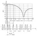
일반적으로 무선통신시스템의 송신단에서는 DAC(Digital to Analog Converter) 장치가 구비되어 디지털 신호를 아날로그 신호로 변환하는 기능이 수행된다. 이처럼, 디지털 신호를 아날로그 신호로 변환할 때, DAC는 이상적인 임펄스(impulse) 신호로 샘플링을 수행하는 것이 아니라, 샘플 앤드 홀드(sample and hold) 방식으로 샘플링을 수행하기 때문에 도 1과 같이 주파수 응답의 진폭이 평평하지 않고 sync 파형과 같이 떨어진다.In general, a digital to analog converter (DAC) device is provided at the transmitting end of a wireless communication system to perform a function of converting a digital signal into an analog signal. As such, when converting a digital signal into an analog signal, the DAC does not perform sampling with an ideal impulse signal, but performs sampling in a sample and hold method. The amplitude is not flat and falls like a sync waveform.
이러한 경우, 도 1의 ①, ②와 같이 상대적으로 대역폭이 작은 협대역 신호의 경우에는 전체 주파수 대역구간에서 감쇄가 많이 나지 않지만, ③과 같이 대역폭이 큰 광대역의 신호는 수 dB의 감쇄가 발생한다.In this case, in the case of a narrowband signal with a relatively small bandwidth as shown in Fig. 1, there is not much attenuation in the entire frequency band section, but a broadband signal with a large bandwidth as shown in ③ has attenuation of several dB. .
이에 따라 광대역 다중-중간주파수(multi-IF) 신호가 송신되는 시스템에서, 각각의 IF 신호들은 DAC를 통과하여 샘플링이 되면 주파수가 높아짐에 따라 신호의 진폭이 더욱더 감쇄되는 주파수 응답 특성을 가지게 된다.Accordingly, in a system in which a wideband multi-IF signal is transmitted, each IF signal has a frequency response characteristic in which the amplitude of the signal is further attenuated as the frequency increases when each IF signal passes through the DAC and is sampled.
본 발명은 다중-중간주파수 신호가 DAC를 통과한 후에도 중간주파수 신호들의 주파수 응답 특성이 감쇄되지 않도록 하는 방법 및 그 장치를 제공하고자 한다.An object of the present invention is to provide a method and apparatus for preventing attenuation of frequency response characteristics of intermediate frequency signals even after a multi-intermediate frequency signal passes through a DAC.
본 발명의 일 실시예에 따른 광대역 신호 송신이득 조절 장치는 복수의 기저대역 디지털 신호들을 생성하고, 생성된 기저대역 디지털 신호들의 이득을 조절하여 출력하는 기저대역 처리기, 상기 기저대역 처리기에서 출력되는 상기 복수의 기저대역 디지털 신호들을 디지털 중간주파수 신호들로 변환하고 변환된 디지털 중간주파수 신호들을 다중화하여 출력하는 다중-중간주파수 변환기 및 상기 다중-중간주파수 변환기에서 출력되는 다중화된 디지털 중간주파수 신호를 아날로그 중간주파수 신호로 변환하는 디지털-아날로그 변환기를 포함할 수 있다.The apparatus for controlling a wideband signal transmission gain according to an embodiment of the present invention includes a baseband processor that generates a plurality of baseband digital signals and adjusts and outputs the gains of the generated baseband digital signals, and the baseband processor outputs the output from the baseband processor. A multi-intermediate frequency converter that converts a plurality of baseband digital signals into digital intermediate frequency signals and multiplexes and outputs the converted digital intermediate frequency signals, and an analog intermediate multiplexed digital intermediate frequency signal output from the multi-intermediate frequency converter. It may include a digital-to-analog converter that converts into a frequency signal.
본 발명의 일 실시예에 따른 광대역 신호 송신이득 조절 장치의 신호 처리 방법은 복수의 기저대역 디지털 신호들을 생성하는 단계, 생성된 상기 복수의 기저대역 디지털 신호들의 이득을 조절하는 단계, 이득이 조절된 기저대역 디지털 신호들을 디지털 중간주파수 신호들로 변환하는 단계, 변환된 디지털 중간주파수 신호들을 다중화하는 단계 및 다중화된 디지털 중간주파수 신호를 아날로그 중간주파수 신호로 변환하는 단계를 포함할 수 있다.The signal processing method of the apparatus for controlling a wideband signal transmission gain according to an embodiment of the present invention includes the steps of generating a plurality of baseband digital signals, adjusting the gains of the generated baseband digital signals, and adjusting the gain. It may include converting the baseband digital signals into digital intermediate frequency signals, multiplexing the converted digital intermediate frequency signals, and converting the multiplexed digital intermediate frequency signals into analog intermediate frequency signals.
본 발명은 다중-중간주파수 신호가 DAC를 통과한 후에도 중간주파수 신호들의 주파수 응답 특성이 감쇄되지 않도록 해준다.The present invention prevents the frequency response characteristics of the intermediate frequency signals from being attenuated even after the multi-intermediate frequency signal passes through the DAC.
도 1은 종래 DAC 샘플링에 따른 주파수 응답 특성을 나타내는 도면.
도 2는 본 발명의 일 실시예에 따른 송신이득 조절 장치의 구성을 나타내는 구성도.
도 3은 도 2에서 기저대역 처리기의 구성을 보다 상세하게 나타낸 구성도.
도 4는 본 발명의 일 실시예에 따른 송신이득 조절 방법을 설명하기 위한 순서도.
도 5는 본 발명에 따른 송신이득 조절 후 DAC 샘플링에 따른 주파수 응답 특성을 나타내는 도면.1 is a diagram showing a frequency response characteristic according to a conventional DAC sampling.
2 is a block diagram showing the configuration of a transmission gain control apparatus according to an embodiment of the present invention.
3 is a block diagram showing the configuration of the baseband processor in FIG. 2 in more detail.
4 is a flow chart for explaining a transmission gain control method according to an embodiment of the present invention.
5 is a diagram showing frequency response characteristics according to DAC sampling after transmission gain adjustment according to the present invention.
이하, 첨부된 도면들을 참조하여 본 발명의 바람직한 실시 예를 보다 상세하게 설명한다. 이에 앞서, 본 명세서 및 청구범위에 사용된 용어나 단어는 통상적이거나 사전적인 의미로 한정해서 해석되어서는 아니 되며, 발명자는 그 자신의 발명을 가장 최선의 방법으로 설명하기 위해 용어의 개념을 적절하게 정의할 수 있다는 원칙에 입각하여 본 발명의 기술적 사상에 부합하는 의미와 개념으로 해석되어야만 한다. 따라서, 본 명세서에 기재된 실시예와 도면에 도시된 구성은 본 발명의 가장 바람직한 일 실시예에 불과할 뿐이고 본 발명의 기술적 사상을 모두 대변하는 것은 아니므로, 본 출원시점에 있어서 이들을 대체할 수 있는 다양한 균등물과 변형예들이 있을 수 있음을 이해하여야 한다.
Hereinafter, preferred embodiments of the present invention will be described in more detail with reference to the accompanying drawings. Prior to this, terms or words used in the specification and claims should not be construed as being limited to their usual or dictionary meanings, and the inventors appropriately explain the concept of terms in order to explain their own invention in the best way. Based on the principle that it can be defined, it should be interpreted as a meaning and concept consistent with the technical idea of the present invention. Accordingly, the embodiments described in the present specification and the configurations shown in the drawings are only the most preferred embodiment of the present invention, and do not represent all the technical spirit of the present invention, and thus various alternatives that can be substituted for them at the time of application It should be understood that there may be equivalents and variations.
도 2는 본 발명의 일 실시예에 따른 송신이득 조절 장치의 구성을 나타내는 구성도로, 다중-중간주파수(multi-IF) 신호를 전송하는 IFoF(Intermediate Frequency over Fiber) 링크를 구성하는 모바일 프론트홀 기지국 시스템에 적용될 수 있다.FIG. 2 is a block diagram showing the configuration of a transmission gain control apparatus according to an embodiment of the present invention, and a mobile fronthaul base station configuring an intermediate frequency over fiber (IFoF) link for transmitting a multi-IF signal Can be applied to the system.
도 2의 송신이득 조절 장치는 기저대역 처리기(100), 다중-중간주파수 변환기(200) 및 디지털-아날로그 변환기(DAC; Digital to Analog Converter)(300)를 포함한다.The transmission gain control apparatus of FIG. 2 includes a
기저대역 처리기(100)는 기저대역 처리된 복수의 디지털 신호들을 개별적으로 생성하고, 디지털-아날로그 변환기(300)의 샘플링 방식에 따른 주파수 응답의 진폭 특성에 따라 복수의 기저대역 디지털 신호들에 대한 송신이득(transmission gain)을 개별적으로 조절하여 다중-중간주파수 변환기(200)에 출력한다. 즉, 기저대역 처리기(100)에는 디지털-아날로그 변환기(300)의 샘플링 방식에 따른 주파수 응답의 진폭 특성 즉 다중-중간주파수 신호가 디지털-아날로그 변환기(300)를 통과하면서 발생되는 각각의 중간주파수에 대한 감쇄량에 대한 정보가 설정되며, 기저대역 처리기(100)는 각각의 기저대역 디지털 신호를 기 설정된 중간주파수별 감쇄량에 대응되게 개별적으로 미리 증폭시켜 다중-중간주파수 변환기(200)에 출력한다.The
다중-중간주파수 변환기(200)는 기저대역 처리기(100)에서 출력되는 복수의 기저대역 디지털 신호들 각각에 서로 다른 중간주파수를 할당하여 디지털 중간주파수 신호들로 변환하고 변환된 디지털 중간주파수 신호들을 다중화하여 디지털-아날로그 변환기(300)에 출력한다. 즉, 다중-중간주파수 변환기(200)는 다중화된 중간주파수(multi-IF) 광대역 신호를 생성하여 디지털-아날로그 변환기(300)에 출력한다.The
디지털-아날로그 변환기(DAC)(300)는 다중화된 디지털 중간주파수 신호(다중-중간주파수 신호)를 아날로그 중간주파수 신호로 변환한다.
The digital-analog converter (DAC) 300 converts the multiplexed digital intermediate frequency signal (multi-intermediate frequency signal) into an analog intermediate frequency signal.
도 3은 도 2에서 기저대역 처리기(100)의 구성을 보다 상세하게 나타낸 구성도이다.FIG. 3 is a block diagram showing the configuration of the
기저대역 처리기(100)는 복수의 모뎀들(112, 114,…, 116), 복수의 증폭기들(122, 124,…, 126) 및 송신이득 조절기(130)를 포함한다.The
복수의 모뎀들(112, 114,…, 116)은 각각 가입자들로부터 인가되는 통신신호(가입자 신호)를 기저대역 디지털 신호로 변환하여 출력한다.The plurality of
복수의 증폭기들(122, 124,…, 126)은 복수의 모뎀들(112, 114,…, 116)과 일대일 대응되게 구비되며, 각 증폭기(122, 124,…, 126)는 대응되는 모뎀(112, 114,…, 116)에서 출력되는 기저대역 디지털 신호를 송신이득 조절기(130)로부터의 이득조절신호에 따라 증폭시켜 다중-중간주파수 변환기(20)에 출력한다. 즉, 증폭기(122, 124,…, 126)는 각각의 대응되는 기저대역 디지털 신호의 이득을 디지털적으로 높여준다.A plurality of amplifiers (122, 124, ..., 126) is provided to correspond to a plurality of modems (112, 114, ..., 116) one-to-one, each amplifier (122, 124, ..., 126) is a corresponding modem ( The baseband digital signal output from 112, 114, ..., 116 is amplified according to the gain control signal from the
송신이득 조절기(130)는 기 설정된 각 중간주파수 별 감쇄량에 따라 각 중간주파수에 대응되는 기저대역 디지털 신호들의 크기를 각각 개별적으로 조절하기 위한 이득조절신호를 생성하여 증폭기들(122, 124,…, 126)에 출력한다. 즉, 송신이득 조절기(130)는 다중-중간주파수 변환기(200)로부터 출력되는 다중화된 디지털 중간주파수 신호의 각 중간주파수의 신호가 디지털-아날로그 변환기(300)를 통과하면서 감쇄되는 양만큼 그 감쇄량에 대응되게 각 기저대역 디지털 신호의 크기를 미리 증가시켜주기 위한 이득조절신호를 발생시켜 증폭기(122, 124,…, 126)에 출력한다. 이때, 각 중간주파수 별 감쇄량은 디지털-아날로그 변환기(300)의 샘플링 방식에 따른 주파수 응답의 진폭 특성으로 인해 디지털 중간주파수 신호들이 디지털-아날로그 변환기(300)를 통과하면서 감쇄되는 양으로서, 디지털-아날로그 변환기(300)가 가지는 고유의 특성값에 의해 결정된다. 따라서 각 중간주파수 별 감쇄량은 무선통신시스템에 사용되는 디지털-아날로그 변환기(300)에 따라 달라질 수 있으며, 시스템 설계시 미리 계산되어 설정된다.
The
도 4는 본 발명의 일 실시예에 따른 송신이득 조절 방법을 설명하기 위한 순서도이다.4 is a flowchart illustrating a transmission gain control method according to an embodiment of the present invention.
도 3의 송신이득 조절 장치에 사용될 디지털-아날로그 변환기(300)가 선정되면, 디지털-아날로그 변환기(300)의 샘플링 방식에 따른 주파수 응답의 진폭 특성을 계산한다(단계 410).When the digital-to-
단계 410에서 계산된 주파수 응답의 진폭 특성을 이용하여 다중-중간주파수 변환기(200)의 각 중간주파수 별로 디지털-아날로그 변환기(300)에 의해 디지털 중간주파수 신호의 크기(진폭)이 어느 정도 감쇄되는지를 확인하여 그 감쇄량에 대한 정보를 메모리(미도시)에 저장하여 설정한다(단계 420).How much the magnitude (amplitude) of the digital intermediate frequency signal is attenuated by the digital-
예컨대 도 1에 도시된 주파수 응답의 경우, 중간주파수들(IF1, IF2,…, IFn)에 대한 주파수 응답의 대푯값은 각각 -0.2dB, -0.8dB,…, -2.5dB이다. 즉, 중간주파수들(IF1, IF2,…, IFn)를 갖는 디지털 중간주파수 신호들은 각각 디지털-아날로그 변환기(300)를 통과하면서 0.2dB, 0.8dB,…, 2.5dB씩 감쇄됨을 알 수 있다.For example, in the case of the frequency response shown in FIG. 1, representative values of the frequency response to the intermediate frequencies IF1, IF2, ..., IFn are -0.2dB, -0.8dB, ... , -2.5dB. That is, the digital intermediate frequency signals having intermediate frequencies (IF1, IF2, ..., IFn) pass through the digital-
이러한, 디지털-아날로그 변환기(300)에 의한 각 중간주파수 별 감쇄량이 미리 계산되어 저장된다.The attenuation amount for each intermediate frequency by the digital-
무선통신시스템이 동작시, 송신이득 조절기(300)는 단계 420에서 기 설정된 중간주파수 별 감쇄량에 대한 정보를 이용하여 각 중간주파수(IF1, IF2,…, IFn)에 대응되는 기저대역 디지털 신호의 크기를 조절하기 위한 이득조절신호를 생성한 후 이를 대응되는 증폭기들(122, 124,…, 126)에 출력한다(단계 430).When the wireless communication system is in operation, the
즉, 각 중간주파수(IF1, IF2,…, IFn)가 디지털-아날로그 변환기(300)에 의해 감쇄되는 양에 따라 각 중간주파수(IF1, IF2,…, IFn)에 대응되는 기저대역 디지털 신호의 크기를 해당 감쇄량 만큼 증폭시키도록 지시하는 이득조절신호가 각 증폭기(122, 124,…, 126)에 인가된다.That is, the size of the baseband digital signal corresponding to each intermediate frequency (IF1, IF2, ..., IFn) according to the amount of each intermediate frequency (IF1, IF2, ..., IFn) attenuated by the digital-analog converter 300 A gain control signal instructing to amplify by the corresponding attenuation amount is applied to each of the
송신이득 조절기(130)로부터 이득조절신호를 수신한 증폭기들(122, 124, …, 126)은 입력되는 기저대역 디지털 신호를 이득조절신호에 따라 증폭하여 이득을 높여준 후 다중-중간주파수 변환기(200)에 출력한다(단계 440).Amplifiers (122, 124, …, 126) receiving the gain control signal from the
예컨대, 디지털-아날로그 변환기(300)가 도 1에서와 같은 주파수 응답을 갖는 경우, 중간주파수(IF1)에 대응되는 기저대역 디지털 신호는 0.2dB 만큼 증폭을 시키고, 중간주파수(IF2)에 대응되는 기저대역 디지털 신호는 0.8dB 만큼 증폭을 시키며, 중간주파수(IFn)에 대응되는 기저대역 디지털 신호는 2.5dB 만큼 증폭을 시킨다.
For example, when the digital-
도 5는 본 발명에 따른 송신이득 조절 후 디지털-아날로그 변환기(300)의 샘플링에 따른 주파수 응답 특성을 나타내는 도면이다.5 is a diagram showing frequency response characteristics according to sampling of the digital-
각 중간주파수((112, 114,…, 116)에 대응되는 기저대역 디지털 신호의 크기를 디지털-아날로그 변환기(300)에 의해 감쇄될 양 만큼 미리 증폭시켜줌으로써, 미리 증폭된 양과 디지털-아날로그 변환기(300)에 의해 감쇄되는 양이 상쇄되어 디지털-아날로그 변환기(300)에서 출력되는 신호들의 주파수 응답은 도 5에서와 같이 진폭이 평평하게 된다.
By amplifying the size of the baseband digital signal corresponding to each intermediate frequency (112, 114, ..., 116) by the amount to be attenuated by the digital-
상술한 본 발명의 바람직한 실시예는 예시의 목적을 위한 것으로, 당업자라면 첨부된 특허청구범위의 기술적 사상과 범위를 통해 다양한 수정, 변경, 대체 및 부가가 가능할 것이며, 이러한 수정 변경 등은 이하의 특허청구범위에 속하는 것으로 보아야 할 것이다.The preferred embodiments of the present invention described above are for the purpose of illustration, and those skilled in the art will be able to make various modifications, changes, substitutions and additions through the technical spirit and scope of the appended claims, and such modifications and changes will be made in the following patents. It should be viewed as falling within the claims.
100 : 기저대역 처리기 112 ~ 116 : 모뎀
122 ~ 126 : 증폭기 130 : 송신이득 조절기
200 : 다중-중간주파수 변환기 300 : 디지털-아날로그 변환기100:
122 ~ 126: amplifier 130: transmission gain controller
200: multi-intermediate frequency converter 300: digital-analog converter
Claims (12)
Translated fromKorean상기 기저대역 처리기에서 출력되는 상기 복수의 기저대역 디지털 신호들을 디지털 중간주파수 신호들로 변환하고 변환된 디지털 중간주파수 신호들을 다중화하여 출력하는 다중-중간주파수 변환기; 및
상기 다중-중간주파수 변환기에서 출력되는 다중화된 디지털 중간주파수 신호를 아날로그 중간주파수 신호로 변환하는 디지털-아날로그 변환기를 포함하며,
상기 기저대역 처리기는 상기 디지털-아날로그 변환기의 샘플링 방식에 따른 주파수 응답의 진폭 특성에 따라 상기 기저대역 디지털 신호들의 이득을 조절하는 것을 특징으로 하는 광대역 신호 송신이득 조절 장치.A baseband processor for generating a plurality of baseband digital signals and adjusting and outputting gains of the generated baseband digital signals;
A multi-intermediate frequency converter converting the plurality of baseband digital signals output from the baseband processor into digital intermediate frequency signals, multiplexing the converted digital intermediate frequency signals, and outputting the multiplexed digital intermediate frequency signals; And
It includes a digital-analog converter for converting the multiplexed digital intermediate frequency signal output from the multi-intermediate frequency converter into an analog intermediate frequency signal,
Wherein the baseband processor adjusts a gain of the baseband digital signals according to an amplitude characteristic of a frequency response according to a sampling method of the digital-to-analog converter.
상기 기저대역 디지털 신호들을 중간주파수 별로 개별적으로 이득을 조절하는 것을 특징으로 하는 광대역 신호 송신이득 조절 장치.The method of claim 1, wherein the baseband processor
A broadband signal transmission gain adjustment apparatus, characterized in that the gain of the baseband digital signals are individually adjusted for each intermediate frequency.
상기 디지털-아날로그 변환기의 특성에 따라 상기 기저대역 디지털 신호들의 이득을 조절하는 것을 특징으로 하는 광대역 신호 송신이득 조절 장치.The method of claim 2, wherein the baseband processor
A broadband signal transmission gain control device, characterized in that the gain of the baseband digital signals is adjusted according to the characteristics of the digital-to-analog converter.
상기 디지털 중간주파수 신호들이 상기 디지털-아날로그 변환기를 통과하면서 감쇄되는 양만큼 상기 기저대역 디지털 신호들을 증폭시키는 것을 특징으로 하는 광대역 신호 송신이득 조절 장치.The method of claim 3, wherein the baseband processor
And amplifying the baseband digital signals by an amount that is attenuated while the digital intermediate frequency signals pass through the digital-analog converter.
상기 복수의 기저대역 디지털 신호들을 개별적으로 생성하는 복수의 모뎀들;
상기 복수의 기저대역 디지털 신호들에 일대일 대응되며, 대응되는 기저대역 디지털 신호를 이득조절신호에 따라 증폭하는 복수의 증폭기들; 및
기 설정된 상기 디지털-아날로그 변환기의 특성에 따라 상기 이득조절신호를 생성하여 상기 증폭기에 출력하는 송신이득 조절기를 포함하는 것을 특징으로 하는 광대역 신호 송신이득 조절 장치.The method of claim 1, wherein the baseband processor
A plurality of modems for individually generating the plurality of baseband digital signals;
A plurality of amplifiers that correspond one-to-one to the plurality of baseband digital signals and amplify the corresponding baseband digital signal according to a gain control signal; And
And a transmission gain adjuster generating the gain control signal according to a predetermined characteristic of the digital-to-analog converter and outputting it to the amplifier.
상기 디지털-아날로그 변환기의 샘플링 방식에 따른 주파수 응답의 진폭 특성에 따라 상기 이득조절신호를 생성하는 것을 특징으로 하는 광대역 신호 송신이득 조절 장치.The method of claim 6, wherein the transmission gain controller
And generating the gain control signal according to an amplitude characteristic of a frequency response according to a sampling method of the digital-analog converter.
상기 복수의 기저대역 디지털 신호들에 서로 다른 중간주파수를 할당하여 디지털 중간주파수 신호들로 변환하는 것을 특징으로 하는 광대역 신호 송신이득 조절 장치.The method of claim 1, wherein the multi-intermediate frequency converter
A broadband signal transmission gain control device, characterized in that for converting the plurality of baseband digital signals into digital intermediate frequency signals by allocating different intermediate frequencies.
생성된 상기 복수의 기저대역 디지털 신호들의 이득을 조절하는 단계;
이득이 조절된 기저대역 디지털 신호들을 디지털 중간주파수 신호들로 변환하는 단계;
변환된 디지털 중간주파수 신호들을 다중화하는 단계; 및
다중화된 디지털 중간주파수 신호를 아날로그 중간주파수 신호로 변환하는 단계를 포함하며,
상기 이득을 조절하는 단계는
상기 다중화된 디지털 중간주파수 신호를 아날로그 중간 주파수 신호로 변환시의 샘플링 방식에 따른 주파수 응답의 진폭 특성에 따라 상기 기저대역 디지털 신호들의 이득을 조절하는 것을 특징으로 하는 광대역 신호 송신이득 조절 장치의 신호 처리 방법.Generating a plurality of baseband digital signals;
Adjusting gains of the generated plurality of baseband digital signals;
Converting the gain-adjusted baseband digital signals into digital intermediate frequency signals;
Multiplexing the converted digital intermediate frequency signals; And
Converting the multiplexed digital intermediate frequency signal to an analog intermediate frequency signal,
The step of adjusting the gain
A signal processing method of a broadband signal transmission gain control apparatus, characterized in that the gain of the baseband digital signals is adjusted according to the amplitude characteristic of the frequency response according to a sampling method when converting the multiplexed digital intermediate frequency signal into an analog intermediate frequency signal. .
상기 기저대역 디지털 신호들의 이득을 중간주파수 별로 개별적으로 조절하는 것을 특징으로 하는 광대역 신호 송신이득 조절 장치의 신호 처리 방법.The method of claim 9, wherein adjusting the gain
A signal processing method of a broadband signal transmission gain control apparatus, characterized in that the gains of the baseband digital signals are individually adjusted for each intermediate frequency.
상기 다중화된 디지털 중간주파수 신호를 아날로그 중간 주파수 신호로 변환시 감쇄되는 양만큼 상기 기저대역 디지털 신호들을 증폭시키는 것을 특징으로 하는 광대역 신호 송신이득 조절 장치의 신호 처리 방법.The method of claim 10, wherein adjusting the gain
And amplifying the baseband digital signals by an amount that is attenuated when converting the multiplexed digital intermediate frequency signal to an analog intermediate frequency signal.
Priority Applications (2)
| Application Number | Priority Date | Filing Date | Title |
|---|---|---|---|
| KR1020150022363AKR102216715B1 (en) | 2015-02-13 | 2015-02-13 | Apparatus for controlling wide-band signal transmission gain in wireless communication systems and signal processing method of the same |
| US15/042,145US9634699B2 (en) | 2015-02-13 | 2016-02-11 | Apparatus for controlling wide-band signal transmission gain in wireless communication systems and signal processing method of the same |
Applications Claiming Priority (1)
| Application Number | Priority Date | Filing Date | Title |
|---|---|---|---|
| KR1020150022363AKR102216715B1 (en) | 2015-02-13 | 2015-02-13 | Apparatus for controlling wide-band signal transmission gain in wireless communication systems and signal processing method of the same |
Publications (2)
| Publication Number | Publication Date |
|---|---|
| KR20160099975A KR20160099975A (en) | 2016-08-23 |
| KR102216715B1true KR102216715B1 (en) | 2021-02-17 |
Family
ID=56621504
Family Applications (1)
| Application Number | Title | Priority Date | Filing Date |
|---|---|---|---|
| KR1020150022363AActiveKR102216715B1 (en) | 2015-02-13 | 2015-02-13 | Apparatus for controlling wide-band signal transmission gain in wireless communication systems and signal processing method of the same |
Country Status (2)
| Country | Link |
|---|---|
| US (1) | US9634699B2 (en) |
| KR (1) | KR102216715B1 (en) |
Families Citing this family (1)
| Publication number | Priority date | Publication date | Assignee | Title |
|---|---|---|---|---|
| KR102478167B1 (en)* | 2016-11-29 | 2022-12-16 | 한국전자통신연구원 | Frequency allocation method and transmission apparatus for performing the method |
Citations (2)
| Publication number | Priority date | Publication date | Assignee | Title |
|---|---|---|---|---|
| WO2014129038A1 (en)* | 2013-02-21 | 2014-08-28 | 三菱電機株式会社 | Relay control station, repeat er, and method for repressing interference |
| WO2015016589A1 (en)* | 2013-08-01 | 2015-02-05 | Samsung Electronics Co., Ltd. | Apparatus and method for adaptive transmission power normalization in wireless communication system |
Family Cites Families (6)
| Publication number | Priority date | Publication date | Assignee | Title |
|---|---|---|---|---|
| US6970717B2 (en)* | 2001-01-12 | 2005-11-29 | Silicon Laboratories Inc. | Digital architecture for radio-frequency apparatus and associated methods |
| KR100480278B1 (en) | 2002-12-24 | 2005-04-07 | 삼성전자주식회사 | Digital predistorter of a wideband power amplifier and adaptation method therefor |
| KR100635011B1 (en) | 2004-11-16 | 2006-10-16 | 한국전자통신연구원 | Transmitter of orthogonal frequency division multiple access system capable of adjusting gain according to the number of subchannels and data transmission method |
| US8422465B2 (en) | 2007-12-17 | 2013-04-16 | Electronics And Telecommunications Research Institute | Transmitter and receiver for high throughput wireless communication system using multiple antenna, method thereof, and digital intermediate frequency transmission signal processing method for the same |
| KR101432100B1 (en) | 2008-12-16 | 2014-08-21 | 에스케이텔레콤 주식회사 | Multi-Band Digital Pre-Distortion Repeater System and Control Method thereof |
| US9037094B2 (en)* | 2011-10-17 | 2015-05-19 | Golba Llc | Method and system for high-throughput and low-power communication links in a distributed transceiver network |
- 2015
- 2015-02-13KRKR1020150022363Apatent/KR102216715B1/enactiveActive
- 2016
- 2016-02-11USUS15/042,145patent/US9634699B2/ennot_activeExpired - Fee Related
Patent Citations (2)
| Publication number | Priority date | Publication date | Assignee | Title |
|---|---|---|---|---|
| WO2014129038A1 (en)* | 2013-02-21 | 2014-08-28 | 三菱電機株式会社 | Relay control station, repeat er, and method for repressing interference |
| WO2015016589A1 (en)* | 2013-08-01 | 2015-02-05 | Samsung Electronics Co., Ltd. | Apparatus and method for adaptive transmission power normalization in wireless communication system |
Also Published As
| Publication number | Publication date |
|---|---|
| US9634699B2 (en) | 2017-04-25 |
| US20160241278A1 (en) | 2016-08-18 |
| KR20160099975A (en) | 2016-08-23 |
Similar Documents
| Publication | Publication Date | Title |
|---|---|---|
| US10009120B2 (en) | Wideband remote unit for distributed antenna system | |
| JP5815154B2 (en) | Relay control station, repeater, and interference suppression method | |
| KR20090081086A (en) | Digital line distortion device and method for sharing feedback path in multi-antenna wireless communication system | |
| CA2566644A1 (en) | Processor-controlled variable gain cellular network amplifier | |
| US10158399B2 (en) | Signal processing method and related device and apparatus | |
| KR102129063B1 (en) | Repeater and method for attenuating a signal | |
| US10644733B2 (en) | Method and system for crest factor reduction | |
| KR102216715B1 (en) | Apparatus for controlling wide-band signal transmission gain in wireless communication systems and signal processing method of the same | |
| JP2013157985A (en) | Automatic gain control device and method, power adjustment device, and radio transmission system | |
| US20230299860A1 (en) | Reception device and a/d conversion method | |
| JP6223216B2 (en) | Relay control station, repeater, and interference avoidance method | |
| KR102502229B1 (en) | 5G millimeter wave band OTA measurement system | |
| KR20170028150A (en) | Digital data compression and decompression module | |
| MX2023000816A (en) | Variable plc attenuator and amplifier. | |
| JP5163527B2 (en) | Amplifier | |
| KR101495113B1 (en) | digital gain automatic control method | |
| KR102262717B1 (en) | Automatic gain controller and method thereof | |
| CN107408975A (en) | digital repeater system | |
| KR20030052195A (en) | An Automatic Gain Control Circuit of Multi-band Modem | |
| US9866246B1 (en) | Digital Transmitter channel optimization device | |
| JP2007124375A (en) | Light receiving circuit and optical transmission system | |
| KR20140103496A (en) | Method for monitoring peak-to-average-ratio of the number of resource blocks of orthogonal frequency division multiplexing signal | |
| KR100908261B1 (en) | Apparatus and method for controlling power timing in a mobile communication terminal | |
| JP2015115694A (en) | Wireless signal transmission system, remote device, master device, and transmission method | |
| JP2009117884A (en) | Wireless communication system and wireless signal synthesis method |
Legal Events
| Date | Code | Title | Description |
|---|---|---|---|
| PA0109 | Patent application | Patent event code:PA01091R01D Comment text:Patent Application Patent event date:20150213 | |
| PG1501 | Laying open of application | ||
| A201 | Request for examination | ||
| PA0201 | Request for examination | Patent event code:PA02012R01D Patent event date:20200114 Comment text:Request for Examination of Application Patent event code:PA02011R01I Patent event date:20150213 Comment text:Patent Application | |
| E902 | Notification of reason for refusal | ||
| PE0902 | Notice of grounds for rejection | Comment text:Notification of reason for refusal Patent event date:20201001 Patent event code:PE09021S01D | |
| E701 | Decision to grant or registration of patent right | ||
| PE0701 | Decision of registration | Patent event code:PE07011S01D Comment text:Decision to Grant Registration Patent event date:20210105 | |
| GRNT | Written decision to grant | ||
| PR0701 | Registration of establishment | Comment text:Registration of Establishment Patent event date:20210209 Patent event code:PR07011E01D | |
| PR1002 | Payment of registration fee | Payment date:20210209 End annual number:3 Start annual number:1 | |
| PG1601 | Publication of registration | ||
| PR1001 | Payment of annual fee | Payment date:20231127 Start annual number:4 End annual number:4 |