KR102214208B1 - Phosphorus or arsenic ion implantation utilizing enhanced source techniques - Google Patents
Phosphorus or arsenic ion implantation utilizing enhanced source techniquesDownload PDFInfo
- Publication number
- KR102214208B1 KR102214208B1KR1020177008882AKR20177008882AKR102214208B1KR 102214208 B1KR102214208 B1KR 102214208B1KR 1020177008882 AKR1020177008882 AKR 1020177008882AKR 20177008882 AKR20177008882 AKR 20177008882AKR 102214208 B1KR102214208 B1KR 102214208B1
- Authority
- KR
- South Korea
- Prior art keywords
- delete delete
- phosphorus
- arsenic
- ion
- ion source
- Prior art date
- Legal status (The legal status is an assumption and is not a legal conclusion. Google has not performed a legal analysis and makes no representation as to the accuracy of the status listed.)
- Active
Links
- 229910052698phosphorusInorganic materials0.000titleclaimsabstractdescription122
- 239000011574phosphorusSubstances0.000titleclaimsabstractdescription119
- OAICVXFJPJFONN-UHFFFAOYSA-NPhosphorusChemical compound[P]OAICVXFJPJFONN-UHFFFAOYSA-N0.000titleclaimsabstractdescription117
- 238000005468ion implantationMethods0.000titleclaimsabstractdescription86
- 238000000034methodMethods0.000titleabstractdescription37
- HAYXDMNJJFVXCI-UHFFFAOYSA-Narsenic(5+)Chemical compound[As+5]HAYXDMNJJFVXCI-UHFFFAOYSA-N0.000titledescription3
- 229910052785arsenicInorganic materials0.000claimsabstractdescription112
- RQNWIZPPADIBDY-UHFFFAOYSA-Narsenic atomChemical compound[As]RQNWIZPPADIBDY-UHFFFAOYSA-N0.000claimsabstractdescription107
- 239000002019doping agentSubstances0.000claimsabstractdescription93
- 239000000463materialSubstances0.000claimsabstractdescription78
- 239000007787solidSubstances0.000claimsabstractdescription62
- 239000000539dimerSubstances0.000claimsabstractdescription43
- 239000002243precursorSubstances0.000claimsdescription51
- 150000001875compoundsChemical class0.000claimsdescription29
- 238000002513implantationMethods0.000claimsdescription26
- 239000012071phaseSubstances0.000claimsdescription22
- 239000012808vapor phaseSubstances0.000claimsdescription14
- 238000012544monitoring processMethods0.000claimsdescription13
- 239000000758substrateSubstances0.000claimsdescription11
- 238000006243chemical reactionMethods0.000claimsdescription8
- 238000004891communicationMethods0.000claimsdescription7
- 239000007943implantSubstances0.000claimsdescription7
- 238000009825accumulationMethods0.000claimsdescription6
- 239000012530fluidSubstances0.000claimsdescription6
- 230000007704transitionEffects0.000claimsdescription2
- 238000002347injectionMethods0.000abstractdescription5
- 239000007924injectionSubstances0.000abstractdescription5
- 230000003190augmentative effectEffects0.000abstract1
- 150000002500ionsChemical class0.000description158
- 239000007789gasSubstances0.000description157
- 239000000203mixtureSubstances0.000description46
- XYFCBTPGUUZFHI-UHFFFAOYSA-NPhosphineChemical compoundPXYFCBTPGUUZFHI-UHFFFAOYSA-N0.000description40
- 229910000073phosphorus hydrideInorganic materials0.000description21
- RBFQJDQYXXHULB-UHFFFAOYSA-NarsaneChemical compound[AsH3]RBFQJDQYXXHULB-UHFFFAOYSA-N0.000description20
- 238000010438heat treatmentMethods0.000description20
- 230000008569processEffects0.000description17
- 238000012546transferMethods0.000description15
- 238000010586diagramMethods0.000description11
- 239000011261inert gasSubstances0.000description11
- 239000006200vaporizerSubstances0.000description10
- 239000012159carrier gasSubstances0.000description9
- 238000004519manufacturing processMethods0.000description9
- 230000008054signal transmissionEffects0.000description9
- 238000009826distributionMethods0.000description8
- 238000000605extractionMethods0.000description8
- 239000003085diluting agentSubstances0.000description7
- -1hydride compoundsChemical class0.000description7
- 150000004678hydridesChemical class0.000description7
- 238000010884ion-beam techniqueMethods0.000description6
- 238000011144upstream manufacturingMethods0.000description6
- KRHYYFGTRYWZRS-UHFFFAOYSA-MFluoride anionChemical compound[F-]KRHYYFGTRYWZRS-UHFFFAOYSA-M0.000description5
- 125000004429atomChemical group0.000description5
- 238000009833condensationMethods0.000description5
- 230000005494condensationEffects0.000description5
- 238000002156mixingMethods0.000description5
- 239000000178monomerSubstances0.000description5
- 238000003860storageMethods0.000description5
- 230000015572biosynthetic processEffects0.000description4
- 230000008859changeEffects0.000description4
- 238000004140cleaningMethods0.000description4
- 230000001276controlling effectEffects0.000description4
- 238000000354decomposition reactionMethods0.000description4
- 230000006872improvementEffects0.000description4
- 239000004065semiconductorSubstances0.000description4
- 238000010521absorption reactionMethods0.000description3
- 230000008901benefitEffects0.000description3
- FFCZHQLUEDCQKI-UHFFFAOYSA-NdiarsenicChemical compound[As]#[As]FFCZHQLUEDCQKI-UHFFFAOYSA-N0.000description3
- 239000007792gaseous phaseSubstances0.000description3
- 229910052732germaniumInorganic materials0.000description3
- GNPVGFCGXDBREM-UHFFFAOYSA-Ngermanium atomChemical compound[Ge]GNPVGFCGXDBREM-UHFFFAOYSA-N0.000description3
- 239000001257hydrogenSubstances0.000description3
- 229910052739hydrogenInorganic materials0.000description3
- 229910052751metalInorganic materials0.000description3
- 239000002184metalSubstances0.000description3
- 238000012986modificationMethods0.000description3
- 230000004048modificationEffects0.000description3
- 230000001629suppressionEffects0.000description3
- 238000009834vaporizationMethods0.000description3
- 230000008016vaporizationEffects0.000description3
- XKRFYHLGVUSROY-UHFFFAOYSA-NArgonChemical compound[Ar]XKRFYHLGVUSROY-UHFFFAOYSA-N0.000description2
- IJGRMHOSHXDMSA-UHFFFAOYSA-NAtomic nitrogenChemical compoundN#NIJGRMHOSHXDMSA-UHFFFAOYSA-N0.000description2
- KRHYYFGTRYWZRS-UHFFFAOYSA-NFluoraneChemical compoundFKRHYYFGTRYWZRS-UHFFFAOYSA-N0.000description2
- UFHFLCQGNIYNRP-UHFFFAOYSA-NHydrogenChemical compound[H][H]UFHFLCQGNIYNRP-UHFFFAOYSA-N0.000description2
- 230000004888barrier functionEffects0.000description2
- 239000011324beadSubstances0.000description2
- 125000004122cyclic groupChemical group0.000description2
- FOBPTJZYDGNHLR-UHFFFAOYSA-NdiphosphorusChemical compoundP#PFOBPTJZYDGNHLR-UHFFFAOYSA-N0.000description2
- 230000000694effectsEffects0.000description2
- BHEPBYXIRTUNPN-UHFFFAOYSA-Nhydridophosphorus(.) (triplet)Chemical compound[PH]BHEPBYXIRTUNPN-UHFFFAOYSA-N0.000description2
- 229910000040hydrogen fluorideInorganic materials0.000description2
- 238000002955isolationMethods0.000description2
- 239000007788liquidSubstances0.000description2
- 230000033001locomotionEffects0.000description2
- WKFBZNUBXWCCHG-UHFFFAOYSA-Nphosphorus trifluorideChemical compoundFP(F)FWKFBZNUBXWCCHG-UHFFFAOYSA-N0.000description2
- 238000012545processingMethods0.000description2
- 239000007790solid phaseSubstances0.000description2
- 238000000859sublimationMethods0.000description2
- 230000008022sublimationEffects0.000description2
- 230000000153supplemental effectEffects0.000description2
- OBSZRRSYVTXPNB-UHFFFAOYSA-NtetraphosphorusChemical compoundP12P3P1P32OBSZRRSYVTXPNB-UHFFFAOYSA-N0.000description2
- OKTJSMMVPCPJKN-UHFFFAOYSA-NCarbonChemical compound[C]OKTJSMMVPCPJKN-UHFFFAOYSA-N0.000description1
- PXGOKWXKJXAPGV-UHFFFAOYSA-NFluorineChemical compoundFFPXGOKWXKJXAPGV-UHFFFAOYSA-N0.000description1
- QORIDDWXQPAYGJ-UHFFFAOYSA-N[AsH3].[AsH3]Chemical compound[AsH3].[AsH3]QORIDDWXQPAYGJ-UHFFFAOYSA-N0.000description1
- 230000002745absorbentEffects0.000description1
- 239000002250absorbentSubstances0.000description1
- 229910052782aluminiumInorganic materials0.000description1
- 238000005280amorphizationMethods0.000description1
- 229910052786argonInorganic materials0.000description1
- 229910000070arsenic hydrideInorganic materials0.000description1
- 230000000712assemblyEffects0.000description1
- 238000000429assemblyMethods0.000description1
- 230000005540biological transmissionEffects0.000description1
- 230000003139buffering effectEffects0.000description1
- 229910052799carbonInorganic materials0.000description1
- 230000005465channelingEffects0.000description1
- UHZZMRAGKVHANO-UHFFFAOYSA-Mchlormequat chlorideChemical group[Cl-].C[N+](C)(C)CCClUHZZMRAGKVHANO-UHFFFAOYSA-M0.000description1
- 239000000470constituentSubstances0.000description1
- 229910052802copperInorganic materials0.000description1
- 238000005336crackingMethods0.000description1
- 239000002178crystalline materialSubstances0.000description1
- 229910021419crystalline siliconInorganic materials0.000description1
- 238000013461designMethods0.000description1
- 238000011161developmentMethods0.000description1
- 238000005516engineering processMethods0.000description1
- 239000002657fibrous materialSubstances0.000description1
- 238000007667floatingMethods0.000description1
- 239000011737fluorineSubstances0.000description1
- 229910052731fluorineInorganic materials0.000description1
- 150000002222fluorine compoundsChemical class0.000description1
- 239000006261foam materialSubstances0.000description1
- 239000011491glass woolSubstances0.000description1
- 229910052736halogenInorganic materials0.000description1
- 150000002367halogensChemical class0.000description1
- 239000001307heliumSubstances0.000description1
- 229910052734heliumInorganic materials0.000description1
- SWQJXJOGLNCZEY-UHFFFAOYSA-Nhelium atomChemical compound[He]SWQJXJOGLNCZEY-UHFFFAOYSA-N0.000description1
- 150000002431hydrogenChemical class0.000description1
- 238000007654immersionMethods0.000description1
- 238000011065in-situ storageMethods0.000description1
- 238000009434installationMethods0.000description1
- 230000003993interactionEffects0.000description1
- 238000012423maintenanceMethods0.000description1
- 230000014759maintenance of locationEffects0.000description1
- 239000006262metallic foamSubstances0.000description1
- 238000004377microelectronicMethods0.000description1
- 229910052754neonInorganic materials0.000description1
- GKAOGPIIYCISHV-UHFFFAOYSA-Nneon atomChemical compound[Ne]GKAOGPIIYCISHV-UHFFFAOYSA-N0.000description1
- 229910052759nickelInorganic materials0.000description1
- 229910052757nitrogenInorganic materials0.000description1
- 238000012856packingMethods0.000description1
- YSWYYGKGAYSAOJ-UHFFFAOYSA-NphosphaneChemical compoundP.PYSWYYGKGAYSAOJ-UHFFFAOYSA-N0.000description1
- 150000003017phosphorusChemical class0.000description1
- 150000003018phosphorus compoundsChemical class0.000description1
- OBCUTHMOOONNBS-UHFFFAOYSA-Nphosphorus pentafluorideChemical compoundFP(F)(F)(F)FOBCUTHMOOONNBS-UHFFFAOYSA-N0.000description1
- 238000002360preparation methodMethods0.000description1
- 230000005855radiationEffects0.000description1
- 239000003870refractory metalSubstances0.000description1
- 230000001105regulatory effectEffects0.000description1
- 230000004044responseEffects0.000description1
- 235000002020sageNutrition0.000description1
- 239000011343solid materialSubstances0.000description1
- 238000001179sorption measurementMethods0.000description1
- 239000000126substanceSubstances0.000description1
- 125000001424substituent groupChemical group0.000description1
- 229910052721tungstenInorganic materials0.000description1
- 229910052724xenonInorganic materials0.000description1
- FHNFHKCVQCLJFQ-UHFFFAOYSA-Nxenon atomChemical compound[Xe]FHNFHKCVQCLJFQ-UHFFFAOYSA-N0.000description1
Images


Classifications
- H—ELECTRICITY
- H01—ELECTRIC ELEMENTS
- H01L—SEMICONDUCTOR DEVICES NOT COVERED BY CLASS H10
- H01L21/00—Processes or apparatus adapted for the manufacture or treatment of semiconductor or solid state devices or of parts thereof
- H01L21/02—Manufacture or treatment of semiconductor devices or of parts thereof
- H01L21/04—Manufacture or treatment of semiconductor devices or of parts thereof the devices having potential barriers, e.g. a PN junction, depletion layer or carrier concentration layer
- H01L21/18—Manufacture or treatment of semiconductor devices or of parts thereof the devices having potential barriers, e.g. a PN junction, depletion layer or carrier concentration layer the devices having semiconductor bodies comprising elements of Group IV of the Periodic Table or AIIIBV compounds with or without impurities, e.g. doping materials
- H01L21/26—Bombardment with radiation
- H01L21/263—Bombardment with radiation with high-energy radiation
- H01L21/265—Bombardment with radiation with high-energy radiation producing ion implantation
- H01L21/2658—Bombardment with radiation with high-energy radiation producing ion implantation of a molecular ion, e.g. decaborane
- H—ELECTRICITY
- H01—ELECTRIC ELEMENTS
- H01J—ELECTRIC DISCHARGE TUBES OR DISCHARGE LAMPS
- H01J37/00—Discharge tubes with provision for introducing objects or material to be exposed to the discharge, e.g. for the purpose of examination or processing thereof
- H01J37/02—Details
- H01J37/04—Arrangements of electrodes and associated parts for generating or controlling the discharge, e.g. electron-optical arrangement or ion-optical arrangement
- H01J37/08—Ion sources; Ion guns
- H—ELECTRICITY
- H01—ELECTRIC ELEMENTS
- H01J—ELECTRIC DISCHARGE TUBES OR DISCHARGE LAMPS
- H01J37/00—Discharge tubes with provision for introducing objects or material to be exposed to the discharge, e.g. for the purpose of examination or processing thereof
- H01J37/02—Details
- H01J37/244—Detectors; Associated components or circuits therefor
- H—ELECTRICITY
- H01—ELECTRIC ELEMENTS
- H01J—ELECTRIC DISCHARGE TUBES OR DISCHARGE LAMPS
- H01J37/00—Discharge tubes with provision for introducing objects or material to be exposed to the discharge, e.g. for the purpose of examination or processing thereof
- H01J37/30—Electron-beam or ion-beam tubes for localised treatment of objects
- H01J37/317—Electron-beam or ion-beam tubes for localised treatment of objects for changing properties of the objects or for applying thin layers thereon, e.g. for ion implantation
- H01J37/3171—Electron-beam or ion-beam tubes for localised treatment of objects for changing properties of the objects or for applying thin layers thereon, e.g. for ion implantation for ion implantation
- H—ELECTRICITY
- H10—SEMICONDUCTOR DEVICES; ELECTRIC SOLID-STATE DEVICES NOT OTHERWISE PROVIDED FOR
- H10F—INORGANIC SEMICONDUCTOR DEVICES SENSITIVE TO INFRARED RADIATION, LIGHT, ELECTROMAGNETIC RADIATION OF SHORTER WAVELENGTH OR CORPUSCULAR RADIATION
- H10F71/00—Manufacture or treatment of devices covered by this subclass
- H—ELECTRICITY
- H01—ELECTRIC ELEMENTS
- H01J—ELECTRIC DISCHARGE TUBES OR DISCHARGE LAMPS
- H01J2237/00—Discharge tubes exposing object to beam, e.g. for analysis treatment, etching, imaging
- H01J2237/006—Details of gas supplies, e.g. in an ion source, to a beam line, to a specimen or to a workpiece
Landscapes
- Physics & Mathematics (AREA)
- Analytical Chemistry (AREA)
- Chemical & Material Sciences (AREA)
- Engineering & Computer Science (AREA)
- High Energy & Nuclear Physics (AREA)
- Manufacturing & Machinery (AREA)
- Condensed Matter Physics & Semiconductors (AREA)
- General Physics & Mathematics (AREA)
- Toxicology (AREA)
- Computer Hardware Design (AREA)
- Microelectronics & Electronic Packaging (AREA)
- Power Engineering (AREA)
- Health & Medical Sciences (AREA)
- Spectroscopy & Molecular Physics (AREA)
- Physical Vapour Deposition (AREA)
- Electron Sources, Ion Sources (AREA)
Abstract
Translated fromKoreanDescription
Translated fromKorean본 발명은 인 또는 비소의 이온 주입에 관한 것이다. 더욱 구체적으로, 본 발명은 고체 도판트 소스 및 고차(higher order) 인 또는 비소 주입 소스 물질의 사용을 위한 향상된 소스 기술, 및 관련 방법 및 기구에 관한 것이다.The present invention relates to ion implantation of phosphorus or arsenic. More specifically, the present invention relates to improved source techniques, and related methods and apparatus for the use of solid dopant sources and higher order phosphorus or arsenic implant source materials.
구체적 양태에서, 본 발명은 상응하는 인 및 비소 클러스터 이온(이량체 및 사량체 포함)의 생성을 위한, 이량체 및 사량체를 비롯한 As 및 P 클러스터 분자의 형성에 관한 것이다. 또한, 본 발명은, 기체 혼합물, 예컨대 (i) PH3 및 PF3, (ii) PH3 및 PF5, (iii) PFx 및 H2, 및 (iv) PFx, PH3, H2, 및 불활성 기체(이때 x는 임의의 화학양론적으로 허용가능한 값을 가지며, 예컨대 3 내지 5의 값을 가짐), 및 상응하는 As계 기체 혼합물의, 소스 수명을 연장시키기 위한 용도에 관한 것이다. 상이한 공급 용기들로부터 프리-믹스 형태로 이온 주입기로 공급되거나 또는 공-유동식으로(as co-flowed) 주입기로 공급되는 이러한 기체 혼합물을 사용하여 이온 주입을 위한 단량체, 이량체, 및 사량체 빔의 빔 전류의 개선을 성취하고 주입기의 개선된 소스 수명을 수득할 수 있으며, 그 이유는, 상기 기체 혼합물은, 단지 하이드라이드 소스 종(AsH3 또는 PH3)만으로 수행하는 경우 주입기 내에서 형성되는 비소 또는 인의 침착물을 최소화하고, 또한 단지 불소화된 소스 종(PF3, PF5, AsF3, or AsF5)만으로 수행하는 경우 일어날 할로겐 영향을 최소화하기 때문이다.In a specific embodiment, the invention relates to the formation of As and P cluster molecules, including dimers and tetramers, for the production of corresponding phosphorus and arsenic cluster ions (including dimers and tetramers). In addition, the present invention provides a gas mixture such as (i) PH3 and PF3 , (ii) PH3 and PF5 , (iii) PFx and H2 , and (iv) PFx , PH3 , H2 , And an inert gas (where x has any stoichiometrically acceptable value, for example a value of 3 to 5), and the use of the corresponding As-based gas mixtures for extending the source lifetime. The monomer, dimer, and tetramer beams for ion implantation using this gas mixture supplied to the implanter in pre-mix form from different feed vessels or as co-flowed to the implanter. An improvement in the beam current can be achieved and an improved source life of the injector can be obtained, because the gas mixture is arsenic formed in the injector when only the hydride source species (AsH3 or PH3 ) is carried out. Or because it minimizes phosphorus deposits, and also minimizes the halogen effects that would occur if performed with only fluorinated source species (PF3 , PF5 , AsF3 , or AsF5 ).
관련 출원에 대한 상호-참조Cross-reference to related applications
35 USC 119 하에 올레그(Oleg Byl) 등의 2014년 9월 1일 출원된 미국 가특허출원 제62/044,409호(명칭: PHOSPHORUS OR ARSENIC ION IMPLANTATION UTILIZING ENHANCED SOURCE TECHNIQUES)의 우선권을 주장한다. 모든 목적에서, 미국 가특허출원 제62/044,409호의 전체 개시내용을 본원에 참고로 인용한다.U.S. Provisional Patent Application No. 62/044,409 (name: PHOSPHORUS OR ARSENIC ION IMPLANTATION UTILIZING ENHANCED SOURCE TECHNIQUES) filed on September 1, 2014 by Oleg Byl et al. under 35 USC 119 claims priority. For all purposes, the entire disclosure of US Provisional Patent Application No. 62/044,409 is incorporated herein by reference.
이온 주입 분야, 예를 들면, 반도체 소자 제조 분야에서, 주입 공정의 효율 개선에 관심이 지속되고 있다. 인 및 비소는 통상적으로 사용되는 도판트 종이다.In the field of ion implantation, for example, in the field of semiconductor device manufacturing, interest in improving the efficiency of an implantation process continues. Phosphorus and arsenic are commonly used dopant species.
통상적 실시에서, 도판트 종에 대한 소스 화합물은 기체, 액체, 또는 고체 형태로 제공된다. 소스 화합물은, 기체 상이 아니면, 고체 형태 또는 액체 형태 소스 화합물로부터 승화 또는 증기화 기술에 의해 휘발화될 수 있다. 그 후, 생성된 도판트 기체는, 플라즈마 함침(immersion) 이온 주입 공정과 같이 직접적으로, 또는 전극 어레이에 의해 이온 종을 분리시켜, 빔 라인 구조체를 통해 가속화되고 기판 상으로 부딪혀 기판에서의 이온 주입을 실시하는 목적 유형의 이온을 함유하는 이온 빔의 형성에 의해 이온화 처리되어 기판에서 주입을 위한 이온 종을 형성한다.In typical practice, the source compound for the dopant species is provided in gaseous, liquid, or solid form. The source compound, if not in a gaseous phase, can be volatilized from the source compound in solid or liquid form by sublimation or vaporization techniques. Thereafter, the generated dopant gas is accelerated through the beam line structure by separating the ionic species directly or by an electrode array, such as in a plasma immersion ion implantation process, and impinges on the substrate to implant ions in the substrate. The ionization treatment is performed by formation of an ion beam containing ions of the desired type to form ionic species for implantation in the substrate.
많은 경우, 이온 주입에 사용되는 도판트 소스 화합물은, 이온화되어 주입용 이온 종을 구성하는 원자에서 일원자성(monoatomic)이다. 제공, 저장 및 가공되어야만 되는 도판트 소스 화합물의 체적의 관점으로부터, 이온화되어, 주입을 위해 이온되는 종을 구성하는 원자에서 다원자성인 도판트 소스 화합물을 사용하는 것이 더욱 바람직하다. 다원자성 도판트 소스 화합물을 사용함에 의해, 도판트 소스 화합물의 단위 체적 당 수득가능한 도판트 이온의 양은 단원자성 도판트 소스 화합물에 비해 실질적으로 증가될 수 있고, 이때 소스 화합물 중의 도판트 원자 수를 증가시키는 것이 일반적으로 더욱 바람직하다. 따라서, 고차 도판트 소스 화합물(소스 화합물 분자 당 보다 많은 수의 도판트 원자)은 저차 도판트 소스 화합물(소스 화합물 분자 당 보다 적은 수의 도판트 원자)에 비해 전형적으로 바람직하다.In many cases, the dopant source compound used for ion implantation is monoatomic in the atoms that are ionized and constitute the ionic species for implantation. From the perspective of the volume of the dopant source compound that must be provided, stored and processed, it is more preferable to use a dopant source compound that is ionized and polyatomic at the atoms constituting the ionized species for implantation. By using the polyatomic dopant source compound, the amount of dopant ions obtainable per unit volume of the dopant source compound can be substantially increased compared to the monoatomic dopant source compound, wherein the number of dopant atoms in the source compound is reduced. It is generally more desirable to increase. Thus, higher order dopant source compounds (more number of dopant atoms per source compound molecule) are typically preferred over lower order dopant source compounds (less number of dopant atoms per source compound molecule).
본 발명은 인 또는 비소의 이온 주입에 관한 것이다.The present invention relates to ion implantation of phosphorus or arsenic.
하나의 양태에서, 본 발명은, 고체 인-포함 또는 비소-포함 물질로 제조되거나 또는 고체 인-포함 또는 비소-포함 물질이 침착된 하나 이상의 벽으로 경계지어진 이온 소스 챔버를 포함하는 이온 주입기를 포함하는 이온 주입 시스템에 관한 것이다.In one embodiment, the present invention comprises an ion implanter comprising an ion source chamber bounded by one or more walls made of a solid phosphorus-comprising or arsenic-comprising material or on which a solid phosphorus-comprising or arsenic-comprising material is deposited. It relates to an ion implantation system.
또 다른 양태에서, 본 발명은In another aspect, the present invention
이온 소스(source) 챔버를 포함하는 이온 주입기; 및An ion implanter including an ion source chamber; And
기상 인 또는 비소 도판트 전구체 물질을 수용하여 이로부터 기상 다원자성 인 또는 기상 다원자성 비소를 형성하도록 구성된 반응기Reactor configured to receive gaseous phosphorus or arsenic dopant precursor material and form gaseous polyatomic phosphorus or gaseous polyatomic arsenic therefrom
를 포함하는 이온 주입 시스템에 관한 것으로서, 이때It relates to an ion implantation system comprising a, wherein
상기 반응기는, 기체 상 물질을 이온 소스 챔버로 전달하여 그 내부에서 이온화하여 이온 주입기에서 기판에 주입하기 위한 주입 종을 형성하도록 배열된 유동 회로망으로 구성되거나 그와 유체 연통식으로 커플링된다.The reactor consists of or is coupled in fluid communication with a flow network arranged to form an implanted species for transferring the gaseous material to the ion source chamber and ionizing it therein to implant it into the substrate in the ion implanter.
추가의 양태에서, 본 발명은In a further aspect, the present invention
이온 소스 챔버를 포함하는 이온 주입기;An ion implanter including an ion source chamber;
상기 이온 소스 챔버로 인-포함 또는 비소-포함 기체 상 전구체를 분배하도록 구성된, 인-포함 또는 비소-포함 기체 상 전구체의 공급원; 및A source of phosphorus-comprising or arsenic-comprising gaseous precursors configured to distribute a phosphorus-comprising or arsenic-comprising gaseous precursor to the ion source chamber; And
상기 공급원으로부터 상기 이온 소스 챔버로 분배된 전구체로부터 유도되는 이온 소스 챔버 내의 고체 다원자성 인 또는 비소를 침착 및 축적시키는 조건 하에서의 제 1 작동 상, 및 이온 주입을 위해 상기 침착된 고체 다원자성 인 또는 비소로부터 이량체 또는 사량체를 포함하는 증기를 생성하는 조건 하에서의 제 2 작동 상으로 상기 이온 소스 챔버를 작동하도록 구성된 모니터링 및 제어 어셈블리A first operating phase under conditions that deposit and accumulate solid polyatomic phosphorus or arsenic in an ion source chamber derived from a precursor distributed from the source to the ion source chamber, and the deposited solid polyatomic phosphorus or arsenic for ion implantation. A monitoring and control assembly configured to operate the ion source chamber in a second operating phase under conditions that produce vapor comprising a dimer or tetramer from
를 포함하는, 이온 주입 시스템에 관한 것이다.It relates to an ion implantation system comprising a.
본 발명의 추가의 양태는A further aspect of the invention
이온 소스 챔버를 포함하는 이온 주입기;An ion implanter including an ion source chamber;
기상 인 또는 비소 전구체 화합물을 함유하는 하나 이상의 소스 용기를 포함하며, 상기 이온 주입기에서 사용하기 위해 상기 전구체 화합물을 분배하도록 구성되는, 도판트 소스 물질 공급 어셈블리; 및A dopant source material supply assembly comprising one or more source containers containing a vapor phase phosphorus or arsenic precursor compound and configured to dispense the precursor compound for use in the ion implanter; And
분배된 기상 인 또는 비소 전구체 화합물을 기상 다원자성 원소 인 또는 비소 물질로 전환시키고, 상기 기상 다원자성 원소 인 또는 비소 물질을 이온 소스 챔버에서 사용하기 위해 제공하여 이로부터 인 또는 비소 주입 종을 생성하도록 구성된, 전환 어셈블리To convert the distributed vapor phase phosphorus or arsenic precursor compound into a vapor phase polyatomic element phosphorus or arsenic material, and to provide the vapor phase polyatomic element phosphorus or arsenic material for use in an ion source chamber to produce phosphorus or arsenic implanted species therefrom. Composed, transition assembly
를 포함하는 이온 주입 시스템에 관한 것이다.It relates to an ion implantation system comprising a.
본 발명의 또 다른 양태는Another aspect of the present invention
이온 소스 챔버를 포함하는 이온 주입기; 및An ion implanter including an ion source chamber; And
상기 이온 주입기에 기체들의 혼합물을 공급하도록 배열된 하나 이상의 기체 공급 용기를 포함하는 기체 공급 어셈블리A gas supply assembly comprising one or more gas supply vessels arranged to supply a mixture of gases to the ion implanter
를 포함하는 이온 주입 시스템에 관한 것으로, 이때 상기 기체들의 혼합물은 하기 (i) 내지 (viii) 중 하나를 포함한다:It relates to an ion implantation system comprising, wherein the mixture of gases comprises one of the following (i) to (viii):
(i) PH3 및 PF3(이때 PH3의 농도는, 기체들의 혼합물의 총 체적을 기준으로 40체적% 내지 60체적% 범위임); (ii) PH3 및 PF5(이때 PH3의 농도는, 기체들의 혼합물의 총 체적을 기준으로 50체적% 내지 75체적% 범위임); (iii) PFx 및 H2(이때 x는 임의의 화학양론적으로 허용가능한 값을 갖고, H2의 농도는, 기체들의 혼합물의 총 체적을 기준으로 50체적% 이하임); (iv) PFx, PH3, H2, 및 불활성 기체(이때 x는 임의의 화학양론적으로 허용가능한 값을 가짐); (v) AsH3 및 AsF3(이때 AsH3의 농도는, 기체들의 혼합물의 총 체적을 기준으로 40체적% 내지 60체적% 범위임); (vi) AsH3 및 AsF5(이때 AsH3의 농도는, 기체들의 혼합물의 총 체적을 기준으로 50체적% 내지 75체적% 범위임); (vii) AsFx 및 H2(이때 x는 임의의 화학양론적으로 허용가능한 값을 갖고, H2의 농도는, 기체들의 혼합물의 총 체적을 기준으로 50체적% 이하임); 및 (viii) AsFx, AsH3, H2, 및 불활성 기체(이때 x는 임의의 화학양론적으로 허용가능한 값을 가짐).(i) PH3 and PF3 (wherein the concentration of PH3 is in the range of 40% by volume to 60% by volume based on the total volume of the mixture of gases); (ii) PH3 and PF5 (wherein the concentration of PH3 is in the range of 50% to 75% by volume based on the total volume of the mixture of gases); (iii) PFx and H2 (where x has any stoichiometrically acceptable value, and the concentration of H2 is less than 50% by volume based on the total volume of the mixture of gases); (iv) PFx , PH3 , H2 , and an inert gas (where x has any stoichiometrically acceptable value); (v) AsH3 and AsF3 (wherein the concentration of AsH3 ranges from 40% to 60% by volume, based on the total volume of the mixture of gases); (vi) AsH3 and AsF5 (wherein the concentration of AsH3 ranges from 50% to 75% by volume, based on the total volume of the mixture of gases); (vii) AsFx and H2 (where x has any stoichiometrically acceptable value, and the concentration of H2 is less than 50% by volume based on the total volume of the mixture of gases); And (viii) AsFx , AsH3 , H2 , and an inert gas, where x has any stoichiometrically acceptable value.
본 발명의 추가의 양태는, 본원에서 다양하게 기재된 바와 같은 본 발명의 이온 주입 시스템의 사용을 포함하는, 이온 주입 방법에 관한 것이다.A further aspect of the present invention relates to a method of ion implantation, including the use of an ion implantation system of the present invention as variously described herein.
본 발명의 추가의 양태는 하기 (i) 내지 (viii)로부터 선택되는 기체 혼합물을 이온 주입기의 이온 소스 챔버에 전달하는 것을 포함하는, 이온 주입기의 성능을 향상시키는 방법에 관한 것이다:A further aspect of the present invention relates to a method of improving the performance of an ion implanter comprising delivering a gas mixture selected from (i) to (viii) to the ion source chamber of the ion implanter:
(i) PH3 및 PF3(이때 PH3의 농도는, 기체들의 혼합물의 총 체적을 기준으로 40체적% 내지 60체적% 범위임); (ii) PH3 및 PF5(이때 PH3의 농도는, 기체들의 혼합물의 총 체적을 기준으로 50체적% 내지 75체적% 범위임); (iii) PFx 및 H2(이때 x는 임의의 화학양론적으로 허용가능한 값을 갖고, H2의 농도는, 기체들의 혼합물의 총 체적을 기준으로 50체적% 이하임); (iv) PFx, PH3, H2, 및 불활성 기체(이때 x는 임의의 화학양론적으로 허용가능한 값을 가짐); (v) AsH3 및 AsF3(이때 AsH3의 농도는, 기체들의 혼합물의 총 체적을 기준으로 40체적% 내지 60체적% 범위임); (vi) AsH3 및 AsF5(이때 AsH3의 농도는, 기체들의 혼합물의 총 체적을 기준으로 50체적% 내지 75체적% 범위임); (vii) AsFx 및 H2(이때 x는 임의의 화학양론적으로 허용가능한 값을 갖고, H2의 농도는, 기체들의 혼합물의 총 체적을 기준으로 50체적% 이하임); 및 (viii) AsFx, AsH3, H2, 및 불활성 기체(이때 x는 임의의 화학양론적으로 허용가능한 값을 가짐).(i) PH3 and PF3 (wherein the concentration of PH3 is in the range of 40% by volume to 60% by volume based on the total volume of the mixture of gases); (ii) PH3 and PF5 (wherein the concentration of PH3 is in the range of 50% to 75% by volume based on the total volume of the mixture of gases); (iii) PFx and H2 (where x has any stoichiometrically acceptable value, and the concentration of H2 is less than 50% by volume based on the total volume of the mixture of gases); (iv) PFx , PH3 , H2 , and an inert gas (where x has any stoichiometrically acceptable value); (v) AsH3 and AsF3 (wherein the concentration of AsH3 ranges from 40% to 60% by volume, based on the total volume of the mixture of gases); (vi) AsH3 and AsF5 (wherein the concentration of AsH3 ranges from 50% to 75% by volume, based on the total volume of the mixture of gases); (vii) AsFx and H2 (where x has any stoichiometrically acceptable value, and the concentration of H2 is less than 50% by volume based on the total volume of the mixture of gases); And (viii) AsFx , AsH3 , H2 , and an inert gas, where x has any stoichiometrically acceptable value.
본 발명의 다른 양태, 특징 및 실시양태는 하기의 발명의 상세한 설명 및 첨부된 특허청구범위로부터 더욱 더 명확해질 것이다.Other aspects, features and embodiments of the present invention will become more apparent from the following detailed description of the invention and the appended claims.
도 1은, 본 발명의 하나의 양태에 따른 이온 주입 공정 시스템의 개략도이다.
도 2는, 본 발명의 또 다른 양태에 따른 이온 주입 공정 시스템의 개략도이다.
도 3은, 본 발명의 추가의 양태에 따른 이온 주입 공정 시스템의 개략도이다.
도 4는, 도판트 소스 기체 공급 라인과 열 전달 관계에 있는, 이온 소스 챔버를 포함하는 이온 주입 공정 시스템의 개략도이다.
도 5는, 도판트 소스 기체 공급 라인을 가열하기 위해 작동식으로 위치된 열 전달 부재와 함께 배열된, 이온 소스 챔버를 포함하는 이온 주입 공정 시스템의 개략도이다.
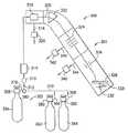
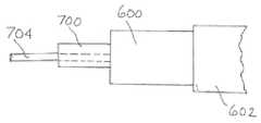
도 6은, 이온 주입 공정 시스템의 이온 소스 챔버로 가는 도판트 소스 기체 공급 라인에 위치되어 다원자성 인(phosphorous) 또는 비소 도판트 종을 생성하는 도판트 소스 기체 반응기이다.1 is a schematic diagram of an ion implantation process system according to one aspect of the present invention.
2 is a schematic diagram of an ion implantation process system according to another aspect of the present invention.
3 is a schematic diagram of an ion implantation process system according to a further aspect of the present invention.
4 is a schematic diagram of an ion implantation process system including an ion source chamber in a heat transfer relationship with a dopant source gas supply line.
5 is a schematic diagram of an ion implantation process system including an ion source chamber, arranged with a heat transfer member operatively positioned to heat a dopant source gas supply line.
6 is a dopant source gas reactor positioned in a dopant source gas supply line going to an ion source chamber of an ion implantation process system to produce a polyatomic phosphorous or arsenic dopant species.
본 발명은 인 또는 비소의 이온 주입에 관한 것이다. 더욱 구체적으로, 본 발명은 고체 도판트 소스 및 고차(higher order) 인 또는 비소 주입 소스 물질의 사용을 위한 향상된 소스 기술, 및 관련 방법 및 기구에 관한 것이다.The present invention relates to ion implantation of phosphorus or arsenic. More specifically, the present invention relates to improved source techniques, and related methods and apparatus for the use of solid dopant sources and higher order phosphorus or arsenic implant source materials.
문맥상 달리 명백히 나타내지 않는 한 단수 형태는 복수의 대상물을 포함한다.Unless the context clearly indicates otherwise, the singular form includes a plurality of objects.
본 발명은, 본 발명의 특징, 양태 및 실시양태와 관련하여 본원에 다양하게 개시된 바와 같이, 구체적인 구현양태에서 상기 특징, 양태 및 실시양태의 일부 또는 전부뿐만 아니라 본 발명의 다양한 추가적인 구현양태를 구성하도록 집합된 이들의 요소 및 구성요소를 포함하거나, 이들로 이루어지거나, 또는 이들로 본질적으로 이루어지는 것으로 구성될 수 있다. 본 발명은 본 발명의 다양한 특징 및 양태에 관하여 본원에 다양한 실시양태로 개시된다. 본 발명은 이러한 특징, 양태 및 실시양태의 다양한 변형 및 조합이 본 발명의 범주 내에 드는 것으로 고려한다. 따라서, 본 발명은 이들 특정 특징, 양태 및 실시양태, 또는 이들 중 선택된 것(들)의 임의의 조합 및 변형을 포함하거나, 이들로 이루어지거나, 또는 이들로 본질적으로 이루어지는 것으로 구체화된다.The present invention, as variously disclosed herein in connection with the features, aspects and embodiments of the invention, constitutes some or all of these features, aspects and embodiments in specific embodiments, as well as various additional embodiments of the invention. It may be configured to include, consist of, or consist essentially of these elements and components as set up to be. The invention is disclosed herein in various embodiments with respect to various features and aspects of the invention. The present invention contemplates that various modifications and combinations of these features, aspects and embodiments are within the scope of the present invention. Accordingly, the present invention is embodied as including, consisting of, or consisting essentially of these specific features, aspects and embodiments, or any combination and variation of the selected one(s) thereof.
본 발명의 화합물, 조성물, 특징, 단계 및 방법은 본원에 개시된 이들의 다양한 사양 및 예시와 관련하여, 적용가능하다면, 특정 치환기, 동위원소, 잔기, 구조, 성분, 특징, 단계 또는 조건을 배제하는 단서 또는 한정에 의해 특정 실시양태로 더 구체화된다.The compounds, compositions, features, steps, and methods of the present invention, when applicable, exclude certain substituents, isotopes, moieties, structures, components, features, steps or conditions with respect to their various specifications and examples disclosed herein. Further embodied in specific embodiments by clue or limitation.
본 발명의 이온 주입 시스템 및 방법은, 본 발명의 도판트 소스 조성물 및 방법을 사용하지 않은 상응하는 이온 주입 시스템 및 방법에 대해 향상된 이온 소스 수명을 달성한다.The ion implantation systems and methods of the present invention achieve improved ion source lifetime over the corresponding ion implantation systems and methods that do not employ the dopant source compositions and methods of the present invention.
도면을 참고하면, 도 1은 본 발명의 하나의 양태에 따른 이온 주입 공정 시스템의 개략도로서, 여기서 본 발명의 인 및 비소 주입 방법이 수행된다.Referring to the drawings, FIG. 1 is a schematic diagram of an ion implantation process system according to an aspect of the present invention, wherein the phosphorus and arsenic implantation method of the present invention is performed.
이온 주입 공정 시스템(300)은, 예시된 이온 주입 챔버(301)에서 기판(328)의 이온 주입 도핑을 위해 공급되는 도판트 기체를 보유하는 내부 공간을 갖는 저장 및 분배 용기(302)를 포함한다. 저장 및 분배 용기는, 도판트 기체가 기체의 저장을 위해 물리적으로 흡착되는 흡수 매질을 함유하는 유형의 것일 수 있으며, 이때 상기 기체는 상기 용기로부터 배출되기 위해, 분배 조건 하에, 상기 흡수 매질로부터 탈착된다. 흡수 매질은 고체-상 탄소 흡착 물질일 수 있다. 이러한 유형의 흡수제-기반 용기는 SDS 및 SAGE 상표명으로 엔테그리스 인코포레이티드(미국 메사추세츠주 빌레리카 소재)로부터 상업적으로 입수가능하다. 다르게는, 상기 용기는 용기 내부 공간 내에 하나 이상의 압력 조절기를 함유하는 내부 압력-조절 유형의 것일 수 있다. 이러한 압력-조절형 용기는 VAC 상표명으로 엔테그리스 인코포레이티드(미국 메사추세츠주 빌레리카 소재)로부터 상업적으로 입수가능하다. 다르게는, 상기 용기는, 예를 들면 상기 용기 및/또는 이의 내용물의 가열에 의해 휘발되어 증기화 또는 승화 생성물로서 도판트 기체를 생성하는 고체 형태의 도판트 소스 물질을 함유할 수 있다. 이러한 유형의 고체 전달 용기는 프로에바프(ProEvap) 상표명으로 엔테그리스 인코포레이티드(미국 메사추세츠주 빌레리카 소재)로부터 상업적으로 입수가능하다.The ion
도 1에서, 저장 및 분배 용기(302)는, 흡착된 상태, 유리 기체 상태 또는 액화된 기체 상태로 도판트 기체를 보유하는 내부 용적을 둘러싸는(enclosing) 실린더형 용기 벽(304)을 포함한다.In Figure 1, the storage and dispensing
저장 및 분배 용기(302)는, 혼합 챔버(360)(임의적임)를 갖는, 분배 라인(372)을 통해 기체 유동 연통식으로 커플링되며, 후에 배출 라인(312)으로 연결되는 밸브 헤드(308)을 포함한다. 압력 센서(310)는 물질(mass) 유동 제어기(314)와 함께 라인(312)에 배치될 수 있고; 다른 임의적 모니터링 및 감지 구성요소가 상기 라인에 커플링되고, 제어 수단, 예컨대 액추에이터(actuator), 피드백 및 컴퓨터 제어 시스템, 사이클 타이머 등과 접속될 수 있다.The storage and dispensing
또한, 혼합 챔버(360)는, 사용되는 경우, 기체 공급 라인(370)과 유동 연통식으로 연결될 수 있고, 이는 보충적 기체 공급 용기(362 및 364)에 연결되고, 이들 각각은 서로 동일하거나 상이할 수 있고, 이는 전술된 용기(302)에 대해 동일하거나 상이한 유형의 것일 수 있다. 용기(362)는 예컨대 희석제 기체를 함유하고, 도판트 기체 혼합물이 제조될 수 있도록 배열된 용기(364)는, 예컨대 희석제 기체 및/또는 공-종 기체와 함께 도판트 기체를 함유하는 공-종(co-species) 기체를 함유할 수 있다.In addition, the mixing chamber 360, if used, may be connected in flow communication with the gas supply line 370, which is connected to the supplementary
보충 용기(supplemental vessel)(362)는, 후에 보충 용기 공급 라인(366)과 커플링되는 밸브 헤드(380)가 고정되는 주 컨테이너 부분과 함께 형성된다. 유사한 방식으로, 보충 용기(364)는 밸브 헤드(382)가 고정되는 주 컨테이너 부분과 함께 형성된다. 밸브 헤드(382)는 보충 용기 공급 라인(368)과 커플링된다. 이러한 배열에 의한 공급 라인(366 및 368)은 희석제 및/또는 공-종 기체(들)을 혼합 챔버(360)로 전달하여 주입기의 이온 소스로의 경로에 희석제 및/또는 공-종 기체(들)을 함유하는 도판트 기체 혼합물을 제공한다. 이러한 목적을 위해, 보충 용기 공급 라인(366 및 368), 및 분배 라인(372)은, 상기 용기로부터 분배되는 물질들의 유동 또는 다른 특징을 수동식으로 또는 자동식으로 제어하기에 적합한 밸브, 제어기 및/또는 센서가 구비될 수 있고, 이러한 밸브, 제어기 및/또는 센서는 임의의 적합한 방식으로 상응하는 공급/분배 라인과 커플링 또는 연결될 수 있다.The
이러한 밸브는, 중앙 처리 유닛(CPU)에 작동적으로 연결되는 밸브 액추에이터와 후에 커플링될 수 있다. CPU는 전술된 제어기 및/또는 센서와 신호 교류 관계적으로 커플링되고, 서로에 대해 속도, 조건 및 각각의 용기로부터 분배되는 유체의 양을 제어하도록 프로그램식으로 배열될 수 있어서, 라인(312)에서의 혼합 챔버(360)로부터 유동되는 도판트 기체 혼합물이 이온 주입 작업을 수행하기 위해 목적하는 조성, 온도, 압력 및 유속을 가질 수 있게 한다.Such a valve can be later coupled with a valve actuator that is operatively connected to a central processing unit (CPU). The CPU is coupled in a signal exchange relationship with the controller and/or sensor described above and can be programmatically arranged to control the speed, conditions and the amount of fluid dispensed from each vessel relative to each other, such that the
예시된 시스템(300)에서, 이온 주입 챔버(301)는, 라인(312)로부터 분배된 도판트 기체 혼합물을 수용하여 이온 빔(305)을 생성하는 이온 소스(316)을 포함한다. 이온 빔(305)은, 필요한 이온을 선택하고, 선택되지 않은 이온은 거부하는 물질 분석기 유닛(322)을 관통한다.In the illustrated
선택된 이온은 가속 전극 어레이(324), 이후 편향(deflection) 전극(326)을 관통한다. 생성된 집속(focused) 이온 빔은 스핀들(332) 상에 배치된 회전식 홀더(330) 상에 배치된 기판 요소(328)에 충돌한다. 도판트 이온의 이온 빔은, 요망되는 바와 같이 기판을 도핑시켜 도핑된 구조체를 형성하기 위해 사용된다.The selected ions pass through the accelerating
이온 주입 챔버(301)의 개별 영역들은 펌프(320, 342 및 346)에 의해 각각 라인(318, 340 및 344)을 통해 배기된다.Individual regions of the ion implantation chamber 301 are evacuated through
도 1에 도시된 유형의 이온 주입 시스템은, 이후 더욱 상세히 기재되는 바와 같이, 본 발명에 따른 인 또는 비소 주입에 사용될 수 있다.Ion implantation systems of the type shown in FIG. 1 can be used for phosphorus or arsenic implantation according to the present invention, as will be described in more detail hereinafter.
현재의 이온 주입 실시에서, 예비-비정질화(amorphization) 주입(PAI)이 기본 반도체 제조 기술로서 통상적으로 이용되며, 여기서 초기 주입 단계는, 후속 주입 단계에서 채널링(channeling)이 방지되도록 기판 물질의 결정질 구조를 의도적으로 파괴하기 위해 이용된다. 게르마늄이 예비-비정질화 주입 종으로서 종종 사용된다. 그러나, 게르마늄의 손상 및 결합 특징부의 양을 제한하기 위해 게르마늄의 대체재가 요구되어, 최종 반도체 제조 생성물의 소자 특성이 영향을 덜 받게 된다.In current ion implantation practices, pre-amorphization implantation (PAI) is commonly used as the basic semiconductor fabrication technique, where the initial implantation step is the crystalline material of the substrate to prevent channeling in the subsequent implantation step. It is used to intentionally destroy structures. Germanium is often used as a pre-amorphized implanted species. However, replacements for germanium are required to limit the amount of damage and bonding features of germanium, so that the device properties of the final semiconductor fabrication product are less affected.
본 발명에 따라, 다원자성 인 및 비소 주입 종은, PAI 적용에서, 예를 들면, P2+ 또는 As2+의 이량체 빔 또는 P4+ 또는 As4+의 사량체 빔으로 사용될 수 있다. 이량체 빔 또는 사량체 빔에서 사용될 수 있다. 직간접적으로 가열된 고온 필라멘트 이온 소스를 사용한 이량체 빔 또는 사량체 빔 생성 및 이량체 또는 사량체 빔 수율은 소스 플라즈마 조건, 이량체 또는 사량체 생성의 효율, 및 보존 효과(retainment effect)에 의해 상당히 영향받을 수 있다. 하나의 양태에서 본 발명은 인-포함 또는 비소-포함 물질로 제조되거나 또는 인-포함 또는 비소-포함 물질이 침착된 하나 이상의 벽으로 경계지어진, 이온 소스 챔버를 포함하는 이온 주입기를 포함하는 이온 주입 시스템의 제공을 고려한다.According to the invention, polyatomic phosphorus and arsenic infused species can be used in PAI applications, for example as a dimer beam of P2+ or As2+ or a tetramer beam of P4+ or As4+. It can be used in either a dimer beam or a tetramer beam. Dimer or tetramer beam generation and dimer or tetramer beam yield using a directly or indirectly heated hot filament ion source is determined by the source plasma conditions, the efficiency of dimer or tetramer generation, and the retention effect. It can be quite affected. In one embodiment the present invention provides an ion implantation comprising an ion implanter comprising an ion source chamber made of a phosphorus-comprising or arsenic-comprising material or bounded by one or more walls in which a phosphorus-comprising or arsenic-comprising material is deposited. Consider the provision of the system.
인의 경우 이온 소스 챔버 벽은 고체 인 또는 인(phosphorous) 화합물 또는 착체로 형성되거나 코팅되어 인 단량체(P+) 또는 인 이량체(P2+) 또는 인 사량체(P4+) 주입 종을 생성할 수 있다. 이에 의해, 이온 소스 챔버에서 생성되는 소스 플라즈마에서의 이량체 이온 집단에 친향적인 인-풍부 환경이 제공된다. 고체 인 또는 인-포함 대체 물질을 이온 소스 챔버 벽 제조 물질로서 사용하여, 인-풍부 소스가 인 이량체의 제공을 위해 제공된다. 이에 의해 이온 주입 시스템은 이량체 주입을 위해 고안된 장치로서 제공된다. 이러한 이온 주입 시스템은, 이온 주입 시스템의 개선된 이량체 빔 성능을 촉진시키는 캐리어 기체 조성물로서 이온 소스 챔버로의 캐리어 기체, 예컨대 하이드라이드 기체, 플루오라이드 기체, 또는 하이드라이드 및 플루오라이드 기체의 혼합물의 유동에 의해 작동될 수 있다.In the case of phosphorus, the ion source chamber wall may be formed or coated with a solid phosphorus or phosphorous compound or complex to produce a phosphorus monomer (P+) or phosphorus dimer (P2+) or phosphorus tetramer (P4+) implanted species. Thereby, an in-rich environment is provided that is friendly to the population of dimer ions in the source plasma generated in the ion source chamber. Using a solid phosphorus or phosphorus-comprising alternative material as the ion source chamber wall preparation material, a phosphorus-rich source is provided for the provision of phosphorus dimers. Thereby the ion implantation system is provided as a device designed for dimer implantation. Such an ion implantation system comprises a carrier gas, such as a hydride gas, a fluoride gas, or a mixture of hydride and fluoride gases, into the ion source chamber as a carrier gas composition that promotes the improved dimer beam performance of the ion implantation system. It can be operated by flow.
이온 소스 챔버에서의 이러한 인 소스 물질의 제공에 의해, 인 이량체 또는 사량체 주입 종은 PAI 작업에서 또는 다른 인 주입 적용에서 사용될 수 있다.By providing such a phosphorus source material in an ion source chamber, phosphorus dimer or tetramer implanted species can be used in PAI operations or in other phosphorus implantation applications.
인 주입과 관련된 전술된 논의는, 비소-포함 물질로 제조되거나 비소-포함 물질이 침착된 하나 이상의 벽으로 경계지어진, 이온 소스 챔버에 의해 마찬가지로 비소 주입에 적용가능하다.The above discussion regarding phosphorus implantation is likewise applicable to arsenic implantation by means of an ion source chamber made of an arsenic-comprising material or bounded by one or more walls on which an arsenic-comprising material is deposited.
도 2는, 상기 논의된 인 또는 비소 주입에서, 또는 다르게는, 본 발명의 넓은 실시에서의 인 또는 비소 주입에서 유용하게 사용될 수 있는 하나의 실시양태에 따른 간접 가열식 캐쏘드(IHC) 이온 소스의 단면형 정면도이다. 도 2는, 아크 챔버 및 관련 구성요소를 도시한다. 이러한 유형의 이온 소스는 마시에조브스키(Maciejowski) 등의 미국 특허 제7,138,768호에 더욱 상세히 기재되어 있다.2 is a diagram of an indirectly heated cathode (IHC) ion source according to one embodiment that may be usefully used in the phosphorus or arsenic implantation discussed above, or alternatively, in the phosphorus or arsenic implantation in the broader practice of the present invention. It is a cross-sectional front view. 2 shows an arc chamber and associated components. Ion sources of this type are described in more detail in US Pat. No. 7,138,768 to Maciejowski et al.
이러한 IHC 이온 소스에서, 추출 어퍼쳐(extraction aperture)(1012)를 갖는 아크 챔버 하우징(1010)은 인-포함 또는 비소-포함 물질로 제조되거나 또는 인-포함 또는 비소-포함 물질이 침착된 벽으로 경계지어진 아크 챔버(1014)를 한정한다. 캐쏘드(1020) 및 리펠러(repeller) 전극(1022)은 아크 챔버(1014) 내에 위치된다. 캐쏘드(1020)에 근접한 아크 챔버(1014) 외부에 위치된 필라멘트(1030)는 캐쏘드의 가열을 생성한다. 캐리어 기체는, 기체 소스(1035)로 가는 기체 공급 라인(1038)에 의해 커플링된 기체 주입구(1034)를 통해 아크 챔버(1014)로 제공될 수 있다. 기체 소스(1035)는, 캐리어 기체를 아크 챔버(1014)로 공급하기 위해, 하이드라이드 기체, 플루오라이드 기체, 또는 하이드라이드 및 플루오라이드 기체 혼합물을 함유하는 공급 용기(들) 또는 다른 소스 구조체를 포함할 수 있다. 하이드라이드 기체는 수소, 수소 플루오라이드, 또는 다른 기상 하이드라이드 화합물을 포함할 수 있다. 플루오라이드 기체는 불소, 수소 플루오라이드, 또는 다른 기상 플루오라이드 화합물을 포함할 수 있다. 상기 캐리어 기체는 공-유동 기체, 희석제, 세정(cleaning) 기체, 또는 다른 기상 구성성분을 포함할 수 있다. 다양한 실시양태에서, 상기 캐리어 기체는 기상 인 화합물, 예컨대 포스핀, 인(phosphorus) 트라이플루오라이드, 포스포러스(phosphorous) 테트라플루오라이드, 또는 이들 중 2개 이상의 혼합물을 포함한다.In such an IHC ion source, the
도 2의 시스템에서, 아크 파워 서플라이는 아크 챔버 하우징(1010)에 연결된 양극 단자(positive terminal) 및 캐쏘드(1020)에 연결된 음극 단자(negative terminal)를 갖는다. 리펠러 전극(1022)은 부유형(floating)일 수 있거나, 아크 파워 서플라이의 음극 단자에 연결될 수 있다. 아크 파워 서플라이는 25 암페어에서 100 볼트의 정격을 가질 수 있고, 약 70 볼트에서 작동될 수 있다. 아크 파워 서플라이는 캐쏘드(1020)에 의해 방출된 전자를 아크 챔버(1014) 내의 플라즈마로 가속시킨다.In the system of FIG. 2, the arc power supply has a positive terminal connected to the
바이어스 파워 서플라이는 캐쏘드(1020)에 연결된 양극 단자 및 필라멘트(1030)에 연결된 음극 단자를 갖는다. 바이어스 파워 서플라이는 4 암페어에서 600 볼트의 정격을 갖고, 약 2.5 암페어의 전류 및 약 350 볼트의 전압에서 작동될 수 있다. 바이어스 파워 서플라이는, 필라멘트(1030)에 의해 방출된 전자를 캐쏘드(1020)로 가속시켜 캐쏘드(1020)의 가열을 생성한다.The bias power supply has a positive terminal connected to the
필라멘트 파워 서플라이는 필라멘트(1030)에 연결된 출력 터미널을 갖는다. 필라멘트 파워 서플라이는 200 암페어에서 6 볼트의 정격을 가질 수 있고, 약 140 내지 170 암페어의 필라멘트 전류에서 작동될 수 있다. 필라멘트 파워 서플라이는, 필라멘트(1030)의 가열을 생성하고, 이는 이후 캐쏘드(1020)의 가열을 위해 캐쏘드(1020)로 가속되는 전자를 생성한다.The filament power supply has an output terminal connected to the
소스 자석은 아크 챔버(1014) 내부에 자기장을 생성한다. 전형적으로, 소스 자석은 아크 챔버(1014)의 반대하는 말단에서 극(pole)을 포함한다. 자기장의 방향은 이온 소스의 작동에 영향을 주지 않으면서 전환될 수 있다. 소스 자석은 자석 파워 서플라이에 연결되고, 이는 60 암페어에서 20 볼트의 정격을 가질 수 있다. 자기장은 캐쏘드(1020)에 의해 방출된 전자와 아크 챔버(1014) 내의 플라즈마 사이의 증가된 상호작용을 생성한다.The source magnet creates a magnetic field inside the
다양한 파워 서플라이의 전압 및 전류 정격 및 작동 전압 및 전류는 단지 예시로서 주어진 것임을 이해할 것이다.It will be appreciated that the voltage and current ratings and operating voltage and current of the various power supplies are given by way of example only.
추출 전극 및 억제(suppression) 전극은 추출 어퍼쳐(1012)의 전면에 적합하게 위치된다. 추출 전극 및 억제 전극은 각각 매우-미세한(well-defined) 이온 빔의 추출을 위해 추출 어퍼쳐(1012)에 의해 정렬되는 어퍼쳐를 갖는다. 추출 전극 및 억제 전극은 개별 파워 서플라이에 연결된다.The extraction electrode and the suppression electrode are suitably positioned in front of the
이온 소스 제어기는 격리 회로(isolation circuit)를 통한 이온 소스의 제어를 제공하기 위해 사용될 수 있다. 다른 실시양태에서, 격리 기능을 수행하기 위한 회로망이 파워 서플라이에 설치될 수 있다. 이온 소스 제어기는 프로그램형 제어기 또는 고안된 특별 목적용 제어기일 수 있다. 하나의 실시양태에서, 이온 소스 제어기는 이온 주입기의 주 제어 컴퓨터로 통합된다.The ion source controller can be used to provide control of the ion source through an isolation circuit. In other embodiments, a network for performing the isolation function may be installed in the power supply. The ion source controller may be a programmable controller or a special purpose controller designed. In one embodiment, the ion source controller is integrated into the main control computer of the ion implanter.
이온 소스가 작동 중인 경우, 필라멘트(1030)는 열이온 방출 온도(이는 약 2200℃일 수 있음)로 필라멘트 전류에 의해 저항식으로 가열된다.When the ion source is in operation, the
필라멘트(1030)에 의해 방출된 전자는 필라멘트(1030)와 캐쏘드(1020) 사이의 바이어스 전압에 의해 가속된다. 캐쏘드(1020)는, 전자 폭격(electron bombardment)에 의해 열이온 방출 온도로 가열된다. 캐쏘드(1020)에 의해 방출된 전자는 아크 전압에 의해 가속되고, 아크 챔버(1014) 내부의 기체 소스로부터 기체 분자를 이온화시켜 플라즈마 방전을 생성한다. 아크 챔버(1014) 내부의 전자는 자기장에 의한 나선형 궤적(trajectories)을 따르도록 유도된다. 리펠러 전극(1022)은 입사 전자의 결과로서 음 전하를 축적하고, 결과적으로 전자를 아크 챔버(1014)를 통해 돌아가게 전자를 밀어내기에 충분한 음 전하를 가져서 추가의 이온화 충돌을 생성한다.Electrons emitted by the
리펠러 전극(1022)을 전도성 지지 부재(support member)(1170)에 의해 아크 챔버 베이스에 설치된다. 캐쏘드(1020)는 아크 챔버 하우징(1010)의 하나의 단부에서의 개구에 설치되지만, 아크 챔버 하우징(1010)과 물리적으로 접촉하지는 않는다. 바람직하게는, 캐쏘드(1020)와 아크 챔버 하우징(1010) 사이의 갭은 약 0.050 인치이다.The
캐쏘드(1020)와 아크 챔버 하우징(1010) 사이에 갭이 존재한다. 필라멘트(1030)의 가열 루프는 컵형 캐버티(cavity)(1240) 내부에 위치되고, 아크 챔버(1014)로부터 필라멘트(1030)로의 플라즈마의 이동이 최소화된다.A gap exists between the
이온 소스는 쉴드(1400)를 추가로 포함할 수 있다. 쉴드(1400)는 캐쏘드(1020) 및 필라멘트(1030)에 근접한 아크 챔버(1014) 외부의 영역(1402)을 실질적으로 둘러 싼다. 쉴드(1400)의 기능은 캐쏘드(1020) 및 필라멘트(1030) 부근에서 전자 및 플라즈마에 대한 장벽을 형성하는 것이다. 쉴드(1400)는 전자 및 플라즈마에 대한 장벽을 형성한다는 의미에서 영역(1402)를 실질적으로 둘러 싸지만, 영역(1402)를 밀봉하지는 않는다.The ion source may further include a
쉴드(1400)는 박스형 구조를 가질 수 있고, 내화 금속으로 제조될 수 있다. 쉴드(1400)는 상부 벽(1412)를 포함한다. 상이한 쉴드 구조(configuration)가 사용될 수 있음을 이해할 것이다. 예컨대, 쉴드(1400)는 평면형 주 벽을 가질 수 있고, 스탠드오프(standoff)를 사용하여 필라멘트 클램프에 설치될 수 있다. 또한, 쉴드(1400)는 이온 소스의 또 다른 요소에 설치될 수 있다.The
본 발명의 실시에서 사용되는 이온 소스는 임의의 적합한 유형의 것일 수 있고, 간접 가열식 캐쏘드(IHC) 이온 소스에 대안적으로, 상기 이온 소스는 버나스(Bernas) 소스, 마이크로파 소스, 라디오 주파수(RF) 소스, 또는 다른 유형의 이온 소스일 수 있다.The ion source used in the practice of the present invention may be of any suitable type, and alternatively to an indirectly heated cathode (IHC) ion source, the ion source may be a Bernas source, a microwave source, a radio frequency ( RF) source, or another type of ion source.
최근의 주입 기술의 방향에 관해서, 보다 작은 노드 크기에 대한 경향에 의해 인 및 비소의 초박형 정션(ultra-shallow junction) 주입의 개발을 위해 지속적으로 노력하고 있다. 이후, 이에 의해 이량체 또는 사량체 빔 전류(예를 들면 P4+, P2+, As4+, As2+)의 개선 필요성이 생긴다. 일반적으로, 인 또는 비소, 예컨대 원소 인 또는 원소 비소의 고체 소스를 사용하는 것은 우수한 이량체 및 사량체 빔 전류를 제공할 수 있는데, 이는 이들 물질이 전형적으로 고체 상에서 As4 및 P4의 형태로 존재하기 때문이고, 이때 생성된 증기는 또한 사량체 형태를 갖는다. 그러나, 고체 소스는 다양한 단점, 예컨대 고체 소스 인 및 비소 물질의 증기화에 필요한 높은 온도에서 밸브 및 물질 유동 제어기(MFC)의 사용 불가능성에 기인한 불량한 유동 제어를 갖는다. 또한, 빔 전류에서의 변화가 요망되는 경우, 고체 소스 기화기의 작동 온도가 변화되어야 하고, 이는 도판트 소스들 사이에서의 스위칭에 대한 장시간 래그(long time lag)를 종종 포함하는데, 이는, 하나의 기화기는, 또 다른 기화기가 목적하는 온도로 가열되는 동안, 냉각되어야 하기 때문이다. 또한, 특히, 기화기가 여전히 뜨거운 경우에 교체하는 동안에, 고체 인 및 비소 물질을 다루는 것과 관련한 상당한 위험성이 존재한다. 또한, 인 및 비소 고체가 기화기의 작동 동안 사용됨에 따라, 빔 전류가 변할 수 있는데, 이는 상기 고체가 증발됨에 따라 열 전달 면적에서의 변화에 기인한다. 또한, 기화기의 사용 동안, 일반적으로, 기화기 내의 인 및 비소 고체의 잔류 인벤토리(inventory)를 결정하는 것은 어렵다.Regarding the direction of the recent implantation technology, there is continuing effort to develop ultra-shallow junction implants of phosphorus and arsenic due to the trend toward smaller node sizes. Thereafter, there arises a need for improvement of the dimer or tetramer beam current (eg P4+, P2+, As4+, As2+) thereby. In general, using a solid source of phosphorus or arsenic, such as elemental phosphorus or elemental arsenic, can provide good dimer and tetramer beam currents, as these materials are typically present in the solid phase in the form of As4 and P4. This is because the vapor produced at this time also has a tetramer form. However, solid sources have various drawbacks, such as poor flow control due to the inability of the valve and material flow controller (MFC) to be used at the high temperatures required for vaporization of solid sources phosphorus and arsenic materials. Also, if a change in beam current is desired, the operating temperature of the solid source vaporizer must be changed, which often includes a long time lag for switching between dopant sources, which is one This is because the vaporizer has to be cooled while another vaporizer is heated to the desired temperature. In addition, there are significant risks associated with handling solid phosphorus and arsenic materials, especially during replacement if the carburetor is still hot. In addition, as the phosphorus and arsenic solids are used during operation of the vaporizer, the beam current may change, due to the change in the heat transfer area as the solids evaporate. Also, during the use of the vaporizer, it is generally difficult to determine the residual inventory of phosphorus and arsenic solids in the vaporizer.
전술된 난점은, 본 발명의 또 다른 양태에서, 이온 소스(source) 챔버를 포함하는 이온 주입기; 및 기상 인 또는 비소 도판트 전구체 물질을 수용하여 이로부터 기상 다원자성 인 또는 기상 다원자성 비소(예컨대 기상 이량체 또는 기상 사량체 인, 또는 기상 이량체 또는 기상 사량체 비소의 형태)을 형성하도록 구성된 반응기를 포함하되, 이때 상기 반응기는, 기체 상 물질을 이온 소스 챔버로 전달하여 그 내부에서 이온화하여 이온 주입기에서 기판에 주입하기 위한 주입 종을 형성하도록 배열된 유동 회로망으로 구성되거나 그와 유체 연통식으로 커플링되는, 이온 주입 시스템의 제공에 의해 해결된다.The above-described difficulty is, in yet another aspect of the present invention, an ion implanter comprising an ion source chamber; And a vapor phase phosphorus or arsenic dopant precursor material to form a vapor phase polyatomic phosphorus or vapor phase polyatomic arsenic (e.g., in the form of a vapor phase dimer or a vapor tetramer phosphorus, or a vapor phase dimer or a vapor tetramer arsenic) therefrom. Including a reactor, wherein the reactor is composed of a flow network arranged to form an implanted species for transferring the gaseous material to the ion source chamber and ionizing it therein to be implanted into the substrate by the ion implanter or in fluid communication therewith. Coupled with the ion implantation system.
예컨대, 상기 반응기는, 인 하이드라이드(포스핀) 또는 비소 하이드라이드(아르신) 도판트 전구체 물질을 분해하여 상응하는 고체 원소 인 또는 비소 및 수소를 형성하여 기상 다원자성 인 또는 기상 다원자성 비소, 예를 들면, 기체 상 이량체 또는 사량체 물질을 생성하도록 구성 및 작동될 수 있다.For example, the reactor may decompose a phosphorus hydride (phosphine) or arsenic hydride (arsine) dopant precursor material to form the corresponding solid elements phosphorus or arsenic and hydrogen to form gaseous polyatomic phosphorus or gaseous polyatomic arsenic, For example, it can be constructed and operated to produce a gaseous dimer or tetrameric material.
또 다른 변형에서, 상기 반응기는, 기체 상 As 또는 P 분자 소스 물질, 예컨대 기상 형태의 아르신 또는 포스핀 또는 다른 비소 또는 인 화합물을 수용하여, 이를, 기체 상(g)으로 존재할 것이며, As(g), P(g), 또는 고차 As 또는 P 기체 상 종, 예컨대 As4(g) 또는 P4(g)의 형태의 것일 수 있는 As 또는 P로 전환하도록 배열될 수 있다.In another variation, the reactor will contain a gaseous As or P molecular source material, such as arsine or phosphine or other arsenic or phosphorus compound in gaseous form, which will exist in the gaseous phase (g), and As( g), P(g), or higher order As or P gas phase species, such as As4(g) or P4(g), which may be arranged to convert to As or P.
추가의 변형에서, 상기 반응기는, 도판트 전구체 물질, 예컨대 하이드라이드 또는 플루오라이드 화합물을 수용하도록 구성될 수 있고, 상기 도판트 전구체 물질을 분해하여 반응기 내부에서 축적 모드로 고체 비소 또는 인을 형성하도록, 사전결정된 양의 고체 원소 비소 또는 인이 축적된 후에 반응기가 높은 온도로 가열되어 상기 고체 원소 비소 또는 인을 증기화시켜 다원자 형태의 기상 비소 또는 인, 예를 들면, 이량체 또는 사량체 형태를 수득하도록 작동될 수 있다.In a further variation, the reactor may be configured to receive a dopant precursor material, such as a hydride or fluoride compound, to decompose the dopant precursor material to form solid arsenic or phosphorus in an accumulation mode inside the reactor. , After a predetermined amount of solid elemental arsenic or phosphorus has been accumulated, the reactor is heated to a high temperature to vaporize the solid elemental arsenic or phosphorus to vaporize gaseous arsenic or phosphorus in polyatomic form, for example in the form of dimers or tetramers. Can be operated to obtain
또 다른 변형에서, 상기 반응기는, 화합물 형태의 도판트 전구체 물질, 예컨대 (아르신 또는 포스핀) 하이드라이드 화합물을 수용한 후, 분해하여 다원자성, 예를 들면, 이량체 또는 사량체 형태의 증기 상 비소 또는 인을 형성하고, 상기 반응기로부터 주입기의 이온 소스 챔버로 연속적으로 유동되도록 배열될 수 있다.In another variation, the reactor contains a dopant precursor material in the form of a compound, such as a (arsine or phosphine) hydride compound, and then decomposes to form a polyatomic, e.g., a dimer or tetramer form of vapor. It can be arranged to form phase arsenic or phosphorus and flow continuously from the reactor to the ion source chamber of the injector.
따라서, 상기 반응기는, 상기 이온 주입 시스템의 기체 전달 라인과 유동 연통식으로 배열되고, 여기서 기상 인 또는 비소 도판트 전구체 물질, 예컨대 포스핀 또는 아르신 기체가 공급 용기 또는 이의 다른 소스로부터 반응기로 유동되도록 배열된다.Thus, the reactor is arranged in flow communication with the gas delivery line of the ion implantation system, wherein a gaseous phosphorus or arsenic dopant precursor material, such as phosphine or arsine gas, flows from the supply vessel or other source thereof to the reactor. Arranged to be possible.
상기 반응기는, 포스핀 또는 아르신이 목적하는 기상 다원자성 원소 인 또는 비소 생성물을 형성하는 제조 공정에서 반응을 일으키기에 충분히 높은 온도에서 유지된다. 목적하는 기상 다원자성 원소 인 또는 비소 생성물은, 이온 소스 챔버로 가는 기체 전달 라인(들)을 통해 반응기로 유동된다. 반응기와 이온 소스 챔버 사이의 기체 전달 라인 및 반응기의 온도는 상기 이온 소스 챔버의 상류의 기상 사량체의 농축을 방지하기에 적합한 수준에서 유지된다.The reactor is maintained at a temperature high enough to cause a reaction in the manufacturing process in which phosphine or arsine forms the desired gaseous polyatomic element phosphorus or arsenic product. The desired gaseous polyatomic element phosphorus or arsenic product is flowed into the reactor via gas delivery line(s) to the ion source chamber. The gas delivery line between the reactor and the ion source chamber and the temperature of the reactor are maintained at a level suitable to prevent concentration of gaseous tetramers upstream of the ion source chamber.
반응기는, 유입되는 포스핀 또는 아르신 도판트 전구체 기체, 또는 다른 인 또는 비소 도판트 전구체 기체의 사전결정된 정도의 반응을 수행하도록 설계될 수 있다. 상기 반응기는 임의의 적합한 크기 및 형태일 수 있고, 예컨대 실린더형, 직사각형, 정사각형 또는 다른 단면 형태의 것일 수 있다. 일부 실시양태에서 반응기는 이온 소스 챔버로 가는 기체 전달 라인의 영역을 포함할 수 있다. 다른 실시양태에서, 이는 상기 반응기의 상류 및 하류에서 기체 전달 라인에 대해 동심형으로(concentrically) 배열될 수 있다. 일반적으로, 인 또는 비소 소스 기체를 분해하고 증기 상 사량체를 생성하기에 효과적인 반응기의 임의의 적합한 설계가 사용될 수 있다. 반응기는 임의의 적합한 방식으로, 예를 들면, 반응기 내부의 또는 반응기와 열 접촉되는 저항식 가열 요소, 본응기의 복사 가열, 반응기의 전도 가열, 반응기의 대류 가열, 또는 인 또는 비소 소스 기체를 분해하여 목적하는 원소 인 또는 비소 생성물을 생성하는데 필요한 온도를 제공하기에 효과적인 임의의 다른 배열 및 열 전달 방식에 의해 가열될 수 있다.The reactor may be designed to carry out a reaction of a predetermined degree of the incoming phosphine or arsine dopant precursor gas, or other phosphorus or arsenic dopant precursor gas. The reactor can be of any suitable size and shape, for example of a cylindrical, rectangular, square or other cross-sectional shape. In some embodiments, the reactor may include a region of gas delivery lines to the ion source chamber. In other embodiments, it can be arranged concentrically with respect to the gas delivery line upstream and downstream of the reactor. In general, any suitable design of the reactor that is effective for cracking the phosphorus or arsenic source gas and producing vapor phase tetramers can be used. The reactor may be in any suitable manner, for example, a resistive heating element in or in thermal contact with the reactor, radiative heating of the main condenser, conduction heating of the reactor, convective heating of the reactor, or decomposition of phosphorus or arsenic source gases. Thus, it can be heated by any other arrangement and mode of heat transfer effective to provide the temperature required to produce the desired elemental phosphorus or arsenic product.
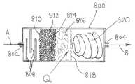
반응기는, 상기 반응기를 포함하는 이온 주입 시스템의 작동에 사용되는 인 또는 비소 소스 기체의 유속에서 인 또는 비소 소스 기체의 목적하는 분해 정도를 수득하는 체류 시간을 제공하도록 적절하게 사이징될 수 있다. 실시양태에서, 반응기는, 반응기를 통해 유동되는 소스 기체로의 향상된 열 전달 및/또는 이의 체류 시간을 제공하는 내부 매질 또는 성분으로 제조될 수 있다. 이러한 내부 매질 또는 성분은, 예컨대 배플, 베인, 스크류 요소, 또는 반응기에서 연정된 기체 유동 경로 및 반응기를 통해 유동하는 기체의 가열을 위해 연장된 열 전달 표면을 제공하는 다른 유동 지시 부재를 포함할 수 있다. 내부 매질 또는 성분은, 추가적으로 또는 대안적으로, 패킹 매질 또는 성분, 예컨대 비드, 금속 포움, 유리 울(glass wool) 등을 포함할 수 있고, 이들은 구불구불한(tortuous) 유동 경로 및 열 전달 향상을 제공한다.The reactor may be suitably sized to provide a residence time to obtain the desired degree of decomposition of the phosphorus or arsenic source gas at the flow rate of the phosphorus or arsenic source gas used in the operation of the ion implantation system comprising the reactor. In embodiments, the reactor may be made of an internal medium or component that provides improved heat transfer and/or residence time thereof to the source gas flowing through the reactor. Such internal media or components may include, for example, baffles, vanes, screw elements, or other flow directing members that provide extended heat transfer surfaces for heating of gas flow paths and gases flowing through the reactor connected to the reactor. have. The inner medium or component may, additionally or alternatively, comprise a packing medium or component such as beads, metal foam, glass wool, etc., which provide a tortuous flow path and improved heat transfer. to provide.
다른 실시양태에서, 반응기는, 이온 주입 시스템의 아크 챔버 주변을 래핑하는 튜브의 형태로 제공되어 상기 튜브 및 내부의 기체 내용물의 가열을 수행할 수 있거나, 또는 반응기는, 플라즈마에 직접 노출되지 않는 아크 챔버의 내부 공간에 배치된 채널의 형태로 제공되어, 예를 들면 목적하는 사량체가 아크 챔버의 채널에서 동일 반응계 내에서 형성되고, 상기 채널로부터 챔버의 내부 용적으로 배출될 수 있다.In another embodiment, the reactor is provided in the form of a tube that wraps around the arc chamber of the ion implantation system to perform heating of the tube and the gas contents therein, or the reactor is an arc that is not directly exposed to plasma. It is provided in the form of a channel disposed in the inner space of the chamber, so that, for example, a desired tetramer is formed in situ in the channel of the arc chamber and discharged from the channel into the inner volume of the chamber.
이온 소스 챔버에 도판트 전구체 기체를 전달하는 유동 회로망에서 사용되는 경우, 반응기는 이러한 회로망의 물질 유동 제어기(MFC)의 상류 또는 하류에 위치될 수 있다. 상기 반응기는 하나의 도판트 전구체 기체에 대해 고안될 수 있거나, 모든 기체가 이온 소스 챔버로 유동되는 공통 라인에 위치될 수 있다. 전술된 바와 같이, 증기 상 원소 인 또는 비소 종은 반응기와 이온 소스 챔버 사이에서 응축되지 않는 것이 필수적이다. 이는 상응하는 유동 회로망의 적절한 온도 제어에 의해 성취될 수 있다. 하나의 실시양태에서, 증기 상 사량체의 응축을 방지하는 필수 온도는, 이온 소스 챔버로부터 1.25 cm 내지 30.5 cm(0.5 내지 12 인치)의 길이에서 이온 소스 챔버로 가는 기체 전달 소스 튜브를 전도식으로 가열하여 수용될 수 있다.When used in a flow network that delivers a dopant precursor gas to an ion source chamber, the reactor may be located upstream or downstream of the mass flow controller (MFC) of such a network. The reactor can be designed for one dopant precursor gas, or it can be located in a common line through which all gases flow into the ion source chamber. As mentioned above, it is essential that the vapor phase elemental phosphorus or arsenic species do not condense between the reactor and the ion source chamber. This can be achieved by appropriate temperature control of the corresponding flow network. In one embodiment, the required temperature to prevent condensation of the vapor phase tetramer is conductively the gas delivery source tube going to the ion source chamber at a length of 1.25 cm to 30.5 cm (0.5 to 12 inches) from the ion source chamber. Can be accommodated by heating.
또 다른 실시양태에서, 열 전달 부재, 예컨대 적합한 금속, 바람직하게는 고 전도성 금속, 예컨대 W, Ni, Cu, Mo, Au, Al 등으로 제조된 금속 클램쉘(clamshell)을 기체 전달 소스 튜브 주변에 위치하되, 이때 상기 클램쉘의 하나의 단부는 이온 소스 챔버와 접촉되어 소스 튜브를 통해 상류에서 가열이 수행될 수 있다.In another embodiment, a heat transfer member, such as a metal clamshell made of a suitable metal, preferably a highly conductive metal, such as W, Ni, Cu, Mo, Au, Al, etc., is placed around the gas transfer source tube. However, at this time, one end of the clamshell may be in contact with the ion source chamber and heating may be performed upstream through the source tube.
또 다른 실시양태에서, 기체 전달 소스 튜브는 저항식 가열 요소에 의해 가열될 수 있거나, 또는 상기 튜브는, 전술된 바와 같이, 상기 이온 소스 챔버 주변으로 래핑될 수 있다.In another embodiment, the gas delivery source tube may be heated by a resistive heating element, or the tube may be wrapped around the ion source chamber, as described above.
반응기에서, 반응은 임의의 적합한 방식, 예를 들면, 반응성 도판트 전구체 기체(예컨대 포스핀 또는 아르신)의 유속을 제어, 반응기의 온도를 제어, 유동 제어 밸브, 유동 제한 오리피스 등의 적절한 사용에 의한 반응기 내부의 압력을 제어함에 의해, 또는 이들의 조합에 의해 제어될 수 있다. 예시적 예로서, 모니터링 및 제어 어셈블리 내의 센서의 적절한 개발에 의해, 사량체의 빔 전류가 모니터링되어 제어기로 전달되는 빔 전류 신호를 생성하고, 이는 이후 이에 응답하여 제어 신호를 전달하여 이러한 목적으로 제공된 적절한 제어식 장치에 의해 유동 및/또는 온도 및/또는 압력을 조절하고, 이때 유동, 온도 및 압력은 모니터링되어 이러한 파라미터의 정밀한 조절을 보장한다.In the reactor, the reaction can be in any suitable manner, for example, controlling the flow rate of the reactive dopant precursor gas (such as phosphine or arsine), controlling the temperature of the reactor, using a flow control valve, flow limiting orifice, etc. By controlling the pressure inside the reactor, or by a combination thereof. As an illustrative example, by appropriate development of the sensor in the monitoring and control assembly, the beam current of the tetramer is monitored to generate a beam current signal that is passed to the controller, which then passes a control signal in response to it provided for this purpose. The flow and/or temperature and/or pressure are regulated by suitable controlled devices, where the flow, temperature and pressure are monitored to ensure precise control of these parameters.
따라서, 반응기는, 상기 챔버로 가는 다른 기체 공급과는 구별되는, 이온 소스 챔버로 가는 별개의 라인에 위치될 수 있거나, 또는 반응기는 이온 소스 챔버로 가는 단일 공통 라인에 위치되어 이온 소스 챔버로 전달되는 모든 기체가 상기 반응기를 관통할 수 있게 한다. 후자의 경우, 반응기는 멈출 수 있거나, 다른 도판트 종이 반응기를 통해 유동될 때에 내부 온도는 제어식으로 저하될 수 있다.Thus, the reactor may be located on a separate line to the ion source chamber, distinct from other gas supply to the chamber, or the reactor may be located on a single common line to the ion source chamber and delivered to the ion source chamber. It allows all gases to be passed through the reactor. In the latter case, the reactor can be stopped, or the internal temperature can be lowered controllably as other dopant species flow through the reactor.
인 또는 비소 도판트 전구체 기체를 분해하여 기체 상 사량체 종을 형성하기 위한 반응기의 제공은, 인 또는 비소 도판트 전구체 기체가 적합한 소스 용기에 공급될 수 있게 한다. 따라서, 도판트는 인 또는 비소의 고체 형태에 대한 노출 없이 하나의 도판트에서 또 다른 것으로 매우 신속하게 스위칭될 수 있고, 도판트 전구체 인벤토리의 모니터링은 용이하게 달성되는데, 이는, 상기 도판트 전구체가 소스 용기로부터 기체의 압력을 모니터링하는 단순한 방편에 의해 기상 형태(예를 들면, 포스핀 또는 아르신으로서) 존재하기 때문이다. 또한, 도판트 전구체가, 먼저 기상 형태로 공급되기 때문에, 빔 전류는 도판트 전구체(포스핀 또는 아르신 기체)의 유속의 제어를 통해 제어될 수 있다. 기체 상 도판트 전구체가 사용되는 경우, 도판트 전구체 공급 용기의 변경에 필요한 시간은, 고체 기화기가 도판트 전구체를 공급하기 위해 사용되는 경우 고체 기화기의 대체에 필요한 시간보다 훨씬 적은데, 이는 소진된 기화기는 냉각시켜야만 하고, 새로운 기화기는 도판트 전구체로 충전되고, 설치되고, 작동 온도로 가열되어야 하기 때문이다.The provision of a reactor for decomposing the phosphorus or arsenic dopant precursor gas to form a gaseous tetrameric species allows the phosphorus or arsenic dopant precursor gas to be supplied to a suitable source vessel. Thus, the dopant can be switched very quickly from one dopant to another without exposure to the solid form of phosphorus or arsenic, and monitoring of the dopant precursor inventory is easily achieved, whereby the dopant precursor is sourced from. This is because it is in gaseous form (eg, as phosphine or arsine) by a simple means of monitoring the pressure of the gas from the vessel. In addition, since the dopant precursor is first supplied in a gas phase form, the beam current can be controlled through control of the flow rate of the dopant precursor (phosphine or arsine gas). When a gaseous dopant precursor is used, the time required to change the dopant precursor supply vessel is much less than the time required to replace the solid vaporizer when a solid vaporizer is used to supply the dopant precursor, which is the exhausted vaporizer. It must be cooled, and the new vaporizer must be filled with the dopant precursor, installed, and heated to the operating temperature.
따라서, 고체 인 또는 비소 소스 물질 사용의 단점 없이 이들의 이익을 동시적으로 수득하면서 인- 또는 비소-함유 기체를 분해하여 기상 도판트 전구체가 사용될 수 있도록 이온 주입 시스템에 반응기를 제공하는 것은 이온 주입 시스템의 실질적 개선을 달성한다.Thus, providing a reactor to the ion implantation system so that the gaseous dopant precursor can be used by decomposing the phosphorus- or arsenic-containing gas while simultaneously obtaining their benefits without the disadvantages of using solid phosphorus or arsenic source materials Achieve substantial improvement of the system.
전술된 및 후술되는 것들을 비롯한 본원에 기재된 이온 주입 시스템은, 매우 다양한 유형의 것일 수 있고, 예컨대 이온 주입기가 빔 라인 주입기인 이온 주입 시스템, 이온 주입기가 태양광 패널 또는 다른 광전 제품의 제조용으로 구성되는 이온 주입 시스템, 또는 이온 주입기가 다른 유형의 것이거나 다른 이온 주입식 구성요소, 구조체, 어셈블리 또는 다른 제품의 제조용으로 특수하게 구성된 이온 주입 시스템을 포함할 수 있음을 이해할 것이다. 따라서, 상기 이온 주입 시스템은 반도체 또는 다른 마이크로전자 제품을 제조하거나, n-형 도너 도판트, 예컨대 인이 결정질 규소 태양광 전지의 제조에서 p-n 정션의 형성에 주입되는 광전지를 제조하기 위해 구성될 수 있다.The ion implantation systems described herein, including those described above and below, can be of a wide variety of types, such as ion implantation systems in which the ion implanter is a beam line implanter, the ion implanter is configured for the manufacture of solar panels or other photovoltaic products. It will be appreciated that the ion implantation system, or ion implanter, may be of a different type or include an ion implantation system specially configured for the manufacture of other implantable components, structures, assemblies or other products. Thus, the ion implantation system can be configured to fabricate a semiconductor or other microelectronic product, or to fabricate a photovoltaic cell in which an n-type donor dopant, such as phosphorus, is implanted in the formation of a pn junction in the fabrication of a crystalline silicon solar cell. have.
추가의 양태에서 본 발명은, 소스 챔버를 포함하는 이온 주입기; 기상 인 또는 비소 전구체 화합물을 함유하는 하나 이상의 소스 용기를 포함하며, 상기 이온 주입기에서 사용하기 위해 상기 전구체 화합물을 분배하도록 구성되는, 도판트 소스 물질 공급 어셈블리; 및 분배된 기상 인 또는 비소 전구체 화합물을 기상 다원자성 원소 인 또는 비소 물질로 전환시키고, 상기 기상 다원자성 원소 인 또는 비소 물질을 이온 소스 챔버에서 사용하기 위해 제공하여 이로부터 인 또는 비소 주입 종을 생성하도록 구성된, 전환 어셈블리를 포함하는 이온 주입 시스템에 관한 것이다.In a further aspect the present invention provides an ion implanter comprising a source chamber; A dopant source material supply assembly comprising one or more source containers containing a vapor phase phosphorus or arsenic precursor compound and configured to dispense the precursor compound for use in the ion implanter; And converting the distributed gaseous phosphorus or arsenic precursor compound into a gaseous polyatomic element phosphorus or arsenic material, and providing the gaseous polyatomic element phosphorus or arsenic material for use in an ion source chamber to produce phosphorus or arsenic implanted species therefrom. It relates to an ion implantation system comprising a conversion assembly configured to.
이러한 이온 주입 시스템에서, 하나의 실시양태에서 전환 어셈블리는, 상기 분배된 기상 인 또는 비소 전구체 화합물을 기상 다원자성 원소 인 또는 비소 물질로 열에 의해 전환시키는 반응기를 포함한다.In such an ion implantation system, in one embodiment the conversion assembly includes a reactor that thermally converts the dispensed gaseous phosphorus or arsenic precursor compound into a gaseous polyatomic elemental phosphorus or arsenic material.
이러한 이온 주입 시스템의 또 다른 실시양태에서, 전환 어셈블리는, 이러한 공급원 어셈블리로부터 상기 이온 소스 챔버로 분배된 전구체 화합물로부터 유도되는 이온 소스 챔버 내의 고체 다원자성 인 또는 비소를 침착 및 축적시키는 조건 하에서의 제 1 작동 상, 및 이온 주입을 위해 상기 침착된 고체 다원자성 인 또는 비소로부터 이량체 또는 사량체를 포함하는 증기를 생성하는 조건 하에서의 제 2 작동 상으로 상기 이온 소스 챔버를 작동하도록 구성된 모니터링 및 제어 어셈블리를 포함한다.In another embodiment of such an ion implantation system, the conversion assembly is a first under conditions to deposit and accumulate solid polyatomic phosphorus or arsenic in an ion source chamber derived from a precursor compound distributed from this source assembly to the ion source chamber. A monitoring and control assembly configured to operate the ion source chamber in an operational phase and a second operational phase under conditions that produce a vapor comprising dimers or tetramers from the deposited solid polyatomic phosphorus or arsenic for ion implantation. Include.
이러한 이온 주입 시스템에서, 전술된 이온 소스 챔버는 제 1 이온 소스 챔버를 포함할 수 있고, 이때 상기 이온 주입 시스템은 제 2 이온 소스 챔버를 포함하며, 이때, 상기 제 2 이온 소스 챔버는, 상기 공급원으로부터 분배된 전구체를 수용하고 제 1 이온 소스 챔버와 동일한 작동 방식으로 작동하지만, 작동 중에 오프셋되어, 상기 제 2 이온 소스 챔버가 제 1 작동 상으로 작동되는 반면 상기 제 1 이온 소스 챔버는 제 2 작동 상으로 작동되도록, 그리고 상기 제 2 이온 소스 챔버가 제 2 작동 상으로 작동되는 반면 상기 제 1 이온 소스 챔버는 제 1 작동 상으로 작동되도록 구성된다.In such an ion implantation system, the ion source chamber described above may comprise a first ion source chamber, wherein the ion implantation system comprises a second ion source chamber, wherein the second ion source chamber comprises the source It receives the precursor dispensed from and operates in the same manner as the first ion source chamber, but is offset during operation, so that the second ion source chamber is operated in the first operating phase while the first ion source chamber is operated in the second operation. The first ion source chamber is configured to be operated with a phase, and the second ion source chamber is operated with a second operative phase while the first ion source chamber is operated with a first operative phase.
따라서, 상기 시스템에는 동일한 주입 장비 내에 2개의 이온 소스에 의해 구현될 수 있으며, 이때 하나는 침착물 축적 모드이고, 다른 것은 주입 모드이거나, 다르게는 모니터링 및 제어 시스템이 2개 이상의 별개의 주입 장비와 함께 사용될 수 있어서, 이들 중 선택된 하나가 제 1 작동 상에 있고, 반면 이들 중 다른 하나는 예들 들면 순환 반복 및 교호적 방식으로 제 2 작동 상에 있으며, 이때 각각의 이온 소스는 연속적안 제 1 및 제 2 작동 상을 진행한다.Thus, the system can be implemented by two ion sources within the same implantation equipment, one in the deposit accumulation mode, the other in the implantation mode, or alternatively the monitoring and control system is different from two or more separate implantation equipment. Can be used together, so that a selected one of them is on the first operation, while the other of them is on the second operation, e.g. in a cyclic iteration and alternating manner, with each ion source being the continuous eye first and Proceed to the second operational phase.
또 다른 양태에서 본 발명은, 이온 소스 챔버를 포함하는 이온 주입기; 및In another aspect, the present invention provides an ion implanter comprising an ion source chamber; And
상기 이온 주입기에 기체들의 혼합물을 공급하도록 배열된 하나 이상의 기체 공급 용기를 포함하는 기체 공급 어셈블리를 포함하는 이온 주입 시스템에 관한 것으로, 이때 상기 기체들의 혼합물은 하기 (i) 내지 (viii) 중 하나를 포함한다:An ion implantation system comprising a gas supply assembly comprising at least one gas supply vessel arranged to supply a mixture of gases to the ion implanter, wherein the mixture of gases comprises one of (i) to (viii) below. Includes:
(i) PH3 및 PF3(이때 PH3의 농도는, 기체들의 혼합물의 총 체적을 기준으로 40체적% 내지 60체적% 범위임); (ii) PH3 및 PF5(이때 PH3의 농도는, 기체들의 혼합물의 총 체적을 기준으로 50체적% 내지 75체적% 범위임); (iii) PFx 및 H2(이때 x는 임의의 화학양론적으로 허용가능한 값을 갖고, H2의 농도는, 기체들의 혼합물의 총 체적을 기준으로 50체적% 이하임); (iv) PFx, PH3, H2, 및 불활성 기체(이때 x는 임의의 화학양론적으로 허용가능한 값을 가짐); (v) AsH3 및 AsF3(이때 AsH3의 농도는, 기체들의 혼합물의 총 체적을 기준으로 40체적% 내지 60체적% 범위임); (vi) AsH3 및 AsF5(이때 AsH3의 농도는, 기체들의 혼합물의 총 체적을 기준으로 50체적% 내지 75체적% 범위임); (vii) AsFx 및 H2(이때 x는 임의의 화학양론적으로 허용가능한 값을 갖고, H2의 농도는, 기체들의 혼합물의 총 체적을 기준으로 50체적% 이하임); 및 (viii) AsFx, AsH3, H2, 및 불활성 기체(이때 x는 임의의 화학양론적으로 허용가능한 값을 가짐). 상기 불활성 기체는, 아르곤, 네온, 질소, 제논, 헬륨, 및 이들 중 2개 이상의 혼합물로 이루어진 군으로부터 선택되는 불활성 기체를 포함할 수 있다.(i) PH3 and PF3 (wherein the concentration of PH3 is in the range of 40% by volume to 60% by volume based on the total volume of the mixture of gases); (ii) PH3 and PF5 (wherein the concentration of PH3 is in the range of 50% to 75% by volume based on the total volume of the mixture of gases); (iii) PFx and H2 (where x has any stoichiometrically acceptable value, and the concentration of H2 is less than 50% by volume based on the total volume of the mixture of gases); (iv) PFx , PH3 , H2 , and an inert gas (where x has any stoichiometrically acceptable value); (v) AsH3 and AsF3 (wherein the concentration of AsH3 ranges from 40% to 60% by volume, based on the total volume of the mixture of gases); (vi) AsH3 and AsF5 (wherein the concentration of AsH3 ranges from 50% to 75% by volume, based on the total volume of the mixture of gases); (vii) AsFx and H2 (where x has any stoichiometrically acceptable value, and the concentration of H2 is less than 50% by volume based on the total volume of the mixture of gases); And (viii) AsFx , AsH3 , H2 , and an inert gas, where x has any stoichiometrically acceptable value. The inert gas may include an inert gas selected from the group consisting of argon, neon, nitrogen, xenon, helium, and a mixture of two or more of them.
또 다른 양태에서, 본 발명은 본원에 다양하게 기재된 이온 주입 시스템의 사용을 포함하는, 이온 주입 방법에 관한 것이다.In yet another aspect, the present invention relates to a method of ion implantation, including use of the ion implantation systems variously described herein.
또 다른 방법 양태에서, 본 발명은 하기 (i) 내지 (viii)로부터 선택되는 기체 혼합물을 이온 주입기의 이온 소스 챔버에 전달하는 것을 포함하는, 이온 주입기의 성능을 향상시키는 방법에 관한 것이다:In yet another method aspect, the present invention relates to a method for improving the performance of an ion implanter comprising delivering a gas mixture selected from (i) to (viii) to the ion source chamber of the ion implanter:
(i) PH3 및 PF3(이때 PH3의 농도는, 기체들의 혼합물의 총 체적을 기준으로 40체적% 내지 60체적% 범위임); (ii) PH3 및 PF5(이때 PH3의 농도는, 기체들의 혼합물의 총 체적을 기준으로 50체적% 내지 75체적% 범위임); (iii) PFx 및 H2(이때 x는 임의의 화학양론적으로 허용가능한 값을 갖고, H2의 농도는, 기체들의 혼합물의 총 체적을 기준으로 50체적% 이하임); (iv) PFx, PH3, H2, 및 불활성 기체(이때 x는 임의의 화학양론적으로 허용가능한 값을 가짐); (v) AsH3 및 AsF3(이때 AsH3의 농도는, 기체들의 혼합물의 총 체적을 기준으로 40체적% 내지 60체적% 범위임); (vi) AsH3 및 AsF5(이때 AsH3의 농도는, 기체들의 혼합물의 총 체적을 기준으로 50체적% 내지 75체적% 범위임); (vii) AsFx 및 H2(이때 x는 임의의 화학양론적으로 허용가능한 값을 갖고, H2의 농도는, 기체들의 혼합물의 총 체적을 기준으로 50체적% 이하임); 및 (viii) AsFx, AsH3, H2, 및 불활성 기체(이때 x는 임의의 화학양론적으로 허용가능한 값을 가짐).(i) PH3 and PF3 (wherein the concentration of PH3 is in the range of 40% by volume to 60% by volume based on the total volume of the mixture of gases); (ii) PH3 and PF5 (wherein the concentration of PH3 is in the range of 50% to 75% by volume based on the total volume of the mixture of gases); (iii) PFx and H2 (where x has any stoichiometrically acceptable value, and the concentration of H2 is less than 50% by volume based on the total volume of the mixture of gases); (iv) PFx , PH3 , H2 , and an inert gas (where x has any stoichiometrically acceptable value); (v) AsH3 and AsF3 (wherein the concentration of AsH3 ranges from 40% to 60% by volume, based on the total volume of the mixture of gases); (vi) AsH3 and AsF5 (wherein the concentration of AsH3 ranges from 50% to 75% by volume, based on the total volume of the mixture of gases); (vii) AsFx and H2 (where x has any stoichiometrically acceptable value, and the concentration of H2 is less than 50% by volume based on the total volume of the mixture of gases); And (viii) AsFx , AsH3 , H2 , and an inert gas, where x has any stoichiometrically acceptable value.
도 3은, 기상 인 또는 비소 도판트 전구체의 분해용 반응기를 사용하는 본 발명의 추가 양태에 따른 이온 주입 공정 시스템의 개략도이다.3 is a schematic diagram of an ion implantation process system according to a further aspect of the present invention using a reactor for decomposition of a gaseous phosphorus or arsenic dopant precursor.
도 3의 시스템에서, 도판트 소스 기체 예컨대 포스핀 또는 아르신을 함유하는 2개의 도판트 소스 기체 용기(402 및 404)가 제공된다. 용기(402, 404)는 분배 챔버(406)에 커플링된다. 이들 용기들은, 용기들 중 하나가 기체를 챔버(406)로 분배하면서, 도판트 소스 기체를 완충 함유하는 다른 것은 준비(standby) 모드에 있도록 통상적으로 배열되며, 이때 상기 용기는 개별 용기의 밸브 헤드 내의 개별 유동 제어 밸브의 적절한 조절에 의해 스위칭될 수 있다. 유동 제어 밸브는, 용기(402 및 404)의 개별 밸브에 적합한 밸브 액추에이터와 커플링된 신호 전달 라인(438 및 440)에 의해 CPU(430)에 작동적으로 연결될 수 있어서, CPU가, 2개의 용기들 중 온-라인된 하나에 의한 분배를 제공하도록 개별 밸브를 제어하게 하며, 이때 다른 용기의 유동 제어 밸브는 폐쇄 조건으로 유지된다. 이에 의해, CPU는, 2개의 용기의 스위칭을 수행할 수 있도록 배열되어, 새롭게 완충된 용기가 이의 유동 제어 밸브의 개방에 의해 분배 모드로 스위칭되고, 소진된 용기가 이전에 개방된 이의 유동 제어 밸브의 폐쇄에 의해 교체(change-out) 모드로 스위칭되도록 한다.In the system of FIG. 3, two dopant
분배 챔버(406)로부터, 분배된 도판트 소스 기체가 압력 센서(410)를 포함하는 분배 라인(408)으로 유동한다. 압력 센서는 신호 전달 라인(436)에 의해 CPU(430)와 신호 전달 관계로 연결된다. 분배 라인(408) 내의 분배된 도판트 소스 기체는 물질 유동 제어기(412)를 통해 유동하여, CPU(430)에 의해 조정될 수 있는 물질 유동 제어기의 설정에 의해 결정된 유속으로 배출되고, 이는 이러한 목적을 위한 제어 신호를 신호 전달 라인(434)의 물질 유동 제어기(412)로 전달하도록 배열된다. 그 후 분배된 도판트 소스 기체는 반응기(416)로 도입된다. 반응기는, 화살표 Q로 표시된 바와 같이 가열되며, 이는 적합한 소스(예를 들면, 임의의 적절한 가열 방식, 예컨대 전도성, 복사성, 대류성 또는 다른 가열 모드에 의해 적합한 승온으로 반응기를 가열하도록 구성된 가열기)로부터 반응기로의 열 전달을 나타낸다).From the dispensing
반응기에서, 도판트 소스 기체는 분해되어 원소 인, 또는 원소 비소를 형성하며, 적용가능한 경우, 이후 상기 원소 물질은 후속 주입용 이량체 또는 사량체 기체 상 물질을 형성한다. 그 후 이량체 또는 사량체 기체 상 물질은 분배 라인(408)의 하류 부분을 통해 이온 주입기(420)로 유동된다. 이량체 또는 사량체 기체 상 물질의 응축을 방지하기 위해, 분배 라인(408)은 가열기(418)에 의해 이러한 응축을 방지하는 적절한 온도로 가열된다. 가열기(418)는 임의의 적합한 가열 기구 또는 장치를 포함할 수 있고, 예컨대 전기 저항 가열 코일로 구성될 수 있다. 이온 주입기(420)에서, 이량체 또는 사량체 기체 상 물질은, 이온화되어 이후에 기판(미도시됨)에 주입되는 주입 종을 형성하기 위해 이온 소스 챔버를 통과한다.In the reactor, the dopant source gas decomposes to form elemental phosphorus, or elemental arsenic, where applicable, then the elemental material to form a dimer or tetramer gaseous material for subsequent injection. The dimer or tetramer gaseous material is then flowed to the
도 3의 시스템은 또한 추가의 기체, 예를 들면, 희석제, 세정 기체, 캐리어 기체, 공-유동 기체 등을 이온 주입기(420)로 공급하는 기체 공급 용기(422 및 424)를 포함한다. 용기(402 및 404)에 대해 전술된 배열과 유사한 방식으로 CPU(430)는 각각 용기(424 및 422)의 유동 제어 밸브 액추에이터로 가는 신호 전달 라인(442 및 444)에 커플링된다. 용기(422)로부터의 기체는 라인(446)에서 분배 챔버(426)로 분배되고, 이는 용기(424)로부터 라인(448)에서 동시에 또는 순차적으로 개별 기체를 수용할 수 있다. 분배 챔버(426)로부터, 기체는 이온 주입기(420)로 가는 물질 유동 제어기(428)를 포함하는 공급 라인(450)으로 유동된다. CPU(430)는 신호 전달 라인(432)에 의해 물질 유동 제어기(428)로 신호 전달 관계로 커플링된다.The system of FIG. 3 also includes
전술된 배열에 의해, CPU(430)는, 신호 전달 라인(436)의 압력 센서(410)으로부터 분배된 도판트 소스 기체 압력의 압력 감지 신호 지시자를 수용하고, CPU는 이온 주입 시스템의 작동을 위해 기체 용기(402, 404, 424, 및 422)의 물질 유동 제어기(412 및 428) 및 유동 제어 밸브의 설정을 응답식으로 또는 독립적으로 조절하도록 구성된다. CPU는 임의의 적합한 유형의 것일 수 있고, 이온 주입 시스템의 모니터링 및 제어 어셈블리의 적절한 센서, 신호 전달 라인 등을 갖는 구성요소로서 예컨대 마이크로프로세서, 프로그램식 로직(logic) 제어기, 특수용 프로그램식 컴퓨터, 또는 이온 주입 시스템의 모니터링 및 제어를 위해 구성 및 작동되는 다른 중앙 처리 유닛을 포함할 수 있다. 구체적으로 도시되지는 않았지만, CPU는 가열기(418)의 출력을 모니터링 및/또는 제어하여 이온 주입기(420)로 공급되는 기체 상 물질로서의 이량체 또는 사량체 도판트 물질의 요망되는 생성 및 유지를 보장하도록 배열 및 구성될 수 있다.By the arrangement described above, the
대안적 이온 주입 공정 시스템 배열이 사용될 수 있음을 인정할 것이다. 예컨대, 기체 공급 용기는, 각각, 고안된 물질 유동 제어기를 포함하는 라인으로 기체를 분배하도록 배열될 수 있고, 이때 개별 기체 라인은 물질 유동 제어기의 하류에서 이온 소스 챔버로 가는 단일 기체 유동 라인으로 합쳐진다. 기상 포스핀 또는 아르신 도판트 소스 화합물을 고차 다원자성 기상 도판트 물질로의 전환을 위한 반응기는 이온 소스 챔버로 가는 이러한 단일 기체 유동 라인에 위치될 수 있다. 개별 기체는 또한 이온 소스로 개별적으로 유동될 수 있거나, 도판트, 캐리어 기체, 세정 기체, 공-종 기체 등의 다중 기체 유동 스트림들 중 별도의 하나의 것들이, 본 발명의 방법 및 기구의 주어진 적용에서 필수적이거나 바람직할 수 있는 경우, 임의의 다양한 순열(permutation)로 합쳐질 수 있어서, 이러한 기체 스트림들의 일부가 이온 소스 챔버의 상류에서 합쳐지는 반면, 다른 것들은 혼합 또는 조합 없이 이온 소스 챔버로 직접 유동된다. 기체 공급 용기에는 액추에이터블(actuatable) 밸브 대신에 수동식 밸브가 구비될 수 있고, 이때 액추에이터블 유동 제어 밸브는 개별 기체 공급 용기로부터 하류에 위치된다.It will be appreciated that alternative ion implantation process system arrangements may be used. For example, the gas supply vessels may be arranged to distribute gas to a line each comprising a mass flow controller designed, wherein the individual gas lines are merged into a single gas flow line downstream of the mass flow controller to the ion source chamber. . A reactor for conversion of a gaseous phosphine or arsine dopant source compound to a higher order polyatomic gaseous dopant material may be located in this single gas flow line to the ion source chamber. Individual gases can also be individually flowed to the ion source, or separate ones of multiple gas flow streams such as dopants, carrier gases, cleaning gases, co-species gases, etc., given application of the method and apparatus of the present invention. Where necessary or desirable, some of these gas streams may be combined in any of a variety of permutations, such that some of these gaseous streams merge upstream of the ion source chamber, while others flow directly into the ion source chamber without mixing or combination. . The gas supply vessel may be provided with a manual valve instead of an actuatable valve, wherein the actuatable flow control valve is located downstream from the individual gas supply vessel.
도 4는, 도판트 소스 기체 공급 라인(604)과 열 전달 관계에 있는, 이온 소스 챔버를 포함하는 이온 주입 공정 시스템(600)의 개략도이다. 이온 소스 챔버(600)는 주입기(602)의 구성요소로서 배열된다. 이러한 실시양태에서, 도판트 소스 기체 공급 라인(604)은 근부 단부(proximal end)(608)로부터 이온 소스 챔버(600) 주위를 나선형으로 래핑하고, 이는 연속적으로 이온 소스를 둘러싸고, 이온 소스 챔버의 표면을 따라 축상으로 연장되는 라인 부분에서 및 이온 소스 챔버(600)의 내부 공간과 기체 유동 연통식으로 교류하는 원부 단부(distal end)(606)에서 종결된다.4 is a schematic diagram of an ion
이러한 배열에서 도판트 소스 기체 공급 라인(604)은 이온 소스 챔버(600)에 의해 가열되고, 이는 작동 시에 승온에 있다. 이러한 방식으로, 공급 라인(604)이 예를 들면, 포스핀 또는 아르신 분해 및 이량체/사량체 형성용 반응기로서 배열되는 경우, 도판트 소스 기체 공급 라인(604)이 기상 이량체 또는 사량체 인 또는 비소 물질이 형성되는 온도로 가열된다. 다르게는, 이러한 기상 이량체 또는 사량체 물질이 라인(604)의 근부 단부(608)의 상류에서 반응기에서 형성되는 경우, 라인(604)은 라인(604)을 통해 이온 소스 챔버(600)로 유동되는 이량체 또는 사량체 물질의 응축을 방지하도록 간략하게 가열된다.In this arrangement the dopant source
도 4의 기구는, 추가의 기체, 예를 들면, 희석제 기체, 캐리어 기체, 세정 기체, 공-유동 기체 등의 이온 소스 챔버(600)로 동시에, 사전에 또는 사후에 유동되는 기체 공급 라인(610)을 추가로 포함한다.The apparatus of FIG. 4 is a
도 5는, 주입기(602)의 일부를 구성하고, 도판트 소스 기체 공급 라인(704)을 가열하도록 작동적으로 배치된 열 전달 부재(700)와 함께 배열된, 이온 소스 챔버를 포함하는 이온 주입 공정 시스템(600)의 개략도이다. 이러한 배열에 의해, 작동 시 이온 소스 챔버(600)에 의해 생성된 열은 기체 공급 라인(704)으로 열 전달 부재(700)에 의해 전도식으로 전달되어 라인(704)의 이온 소스 챔버로 유동하는 도판트 소스 물질의 응축이 일어나지 않게 한다.5 is an ion implantation comprising an ion source chamber, which constitutes part of the
도 6은, 이온 주입 공정 시스템의 이온 소스 챔버로 가는 도판트 소스 기체 공급 라인에 위치된, 다원자성 주입 종을 생성하기 위한 도판트 소스 기체 반응기의 개략도이다. 반응기는, 내부에서 분해되어 이후에 주입을 위한 인 또는 비소 이량체 또는 사량체 물질을 생성하는 원소 인 또는 비소를 형성하는 인-포함 또는 비소-포함 기상 도판트 소스 물질을 수용하도록 개조된다. 상기 반응기는, 화살표 A로 지시되는 바와 같이 반응기의 내부 공간으로 도입되는 인-포함 또는 비소-포함 기상 도판트 소스 물질을 수용하기 위한 주입구(802)를 갖는 하우징(800)을 포함한다. 열 입력(heat input) Q는, 적합한 열원에 의해 반응기로 전달되고, 이는 전도식, 대류식, 복사식 또는 다른 가열기 유형일 수 있다.6 is a schematic diagram of a dopant source gas reactor for generating polyatomic implanted species, located in a dopant source gas supply line to an ion source chamber of an ion implantation process system. The reactor is adapted to contain a phosphorus-comprising or arsenic-comprising gaseous dopant source material that decomposes therein to form elemental phosphorus or arsenic that produces phosphorus or arsenic dimer or tetrameric material for later injection. The reactor includes a
반응기에서 생성된 이량체 또는 사량체 물질은 화살표 B로 지시되는 방향으로 배출구(804)에서 배출된다.The dimer or tetramer material produced in the reactor is discharged from the
반응기는, 연장된 열 전달 표면 및/또는 반응기를 통해 유동하는 물질의 체류 시간의 조절을 제공하는 내부 구조체, 구성요소 또는 물질을 포함할 수 있다. 따라서, 상기 반응기는, 도시된 바와 같이, 연장된 유체 유동 경로를 제공하는 배블(808)을 포함할 수 있다. 추가로, 또는 다르게는, 반응기는 보유 스크린(810 및 814)에 의해 고정식으로 위치되는 베드(bed)에 비드 물질(812)을 포함할 수 있다. 추가로, 또는 다르게는, 반응기는, 도시된 바와 같이, 포라머스 플레이트(foraminous plate)(818)에 의해 반응기의 내부 공간에 고정식으로 위치될 수 있는 섬유질 매트 또는 포움 물질(816)을 포함할 수 있다. 추가로, 또는 다르게는, 반응기는, 반응기를 통해 유동하는 유체에 대한 소용돌이 운동을 부여하는 역할을 하는 나선형 바디(820)를 포함할 수 있다. 반응기는, 반응기에서 목적하는 물질의 가열을 달성하는 역할을 하며 반응기를 통해 유동하는 물질에 적절한 체류 시간을 제공하는 매우 다양한 내부 구성요소 및/또는 물질을 포함할 수 있어서, 이량체 및 사량체 종이 유입된 기상 인-포함 또는 비소-포함 전구체 물질로부터 유리하게 형성될 수 있음을 이해할 것이다.The reactor may include an elongated heat transfer surface and/or an internal structure, component or material that provides control of the residence time of the material flowing through the reactor. Thus, the reactor, as shown, may include a baffle 808 that provides an extended fluid flow path. Additionally, or alternatively, the reactor can include
역사적으로, 고체 인 및 고체 비소는 이온 주입 공정에서 인 및 비소 이온의 생성을 위한 1차 공급 물질로서 사용되었으며, 이때 상기 고체 물질은 가열되어 이온화 및 이온 추출을 위해 이온 소스 챔버로 전달되는 증기를 생성하였다. 인 및 비소 증기는, 이량체로 분해되고, 이들은 승온에서 단량체로 분해되는 사량체(P4 및 As4)로 구성되기 때문에, 고체 인 및 고체 비소가 이량체 및 사량체를 형성하기 위한 이상적 공급 물질이다. 이러한 고체의 사용은 상응하는 단량체(P+ 및 As+)를 생성하는데 보다 편리한 기체 상 전구체, 예컨대 포스핀 및 아르신 때문에 이온 주입 산업분야에서 포기되었고, 고체 인 및 비소 공급 물질 사용으로의 복귀는, 고가의 이온 주입기의 신규 설치 및 이러한 고체 인 및 비소 공급 물질을 수용할 수 있는 새로운 이온 주입 시스템으로의 대체를 요구할 것이다. 포스핀 및 아르신이 특정 조건 하에 이온 주입기 내에서 이량체 및 사량체를 생성하기 위해 사용될 수 있지만, 이러한 이량체 및 사량체는 상업적으로 바람직하지 않을 정도로 낮은 농도도 생성된다.Historically, solid phosphorus and solid arsenic have been used as the primary feed material for the production of phosphorus and arsenic ions in the ion implantation process, where the solid material is heated to transfer vapors to the ion source chamber for ionization and ion extraction. Was created. Since phosphorus and arsenic vapors break down into dimers, and they consist of tetramers (P4 and As4) that break down into monomers at elevated temperatures, solid phosphorus and solid arsenic are ideal feedstocks for forming dimers and tetramers. The use of these solids has been abandoned in the ion implantation industry because of more convenient gaseous precursors such as phosphine and arsine to produce the corresponding monomers (P+ and As+), and the return to the use of solid phosphorus and arsenic feed materials is expensive. It will require a new installation of the ion implanter and replacement with a new ion implantation system that can accommodate these solid phosphorus and arsenic feed materials. Although phosphine and arsine can be used to generate dimers and tetramers in ion implanters under certain conditions, these dimers and tetramers are also produced in commercially undesirably low concentrations.
또 다른 양태에서 본 발명은 이러한 결점을 극복한다. 포스핀 및 아르신이 둘다 승온에서 원소 인 및 비소로 분해되고, 통상의 이온 주입기에서 일어날 공정이, 임의의 고체 원소 인 또는 비소가 (i) 이온 소스 챔버에서의 매우 고온의 결과로서 증발되거나, (ii) 본래의 인 또는 비소 하이드라이드 화합물로부터 유도된 수소와 반응하여, 포스핀 또는 아르신으로서 기체 상으로 되돌아 가거나, (iii) 단량체 이온으로서 이온화되거나, 또는 (iv) 이량체 또는 사량체를 형성하기 전에 이온 소스 챔버로부터 펌핑되어 나오는 것에 의해, 마스킹된다.In another aspect the invention overcomes this drawback. Both phosphine and arsine decompose into elemental phosphorus and arsenic at elevated temperature, and the process that will take place in a conventional ion implanter is that any solid elemental phosphorus or arsenic (i) evaporates as a result of very high temperatures in the ion source chamber, or ( ii) reacts with hydrogen derived from the original phosphorus or arsenic hydride compound to return to the gaseous phase as phosphine or arsine, (iii) ionizes as monomer ions, or (iv) forms dimers or tetramers. It is masked by being pumped out of the ion source chamber prior to doing so.
이러한 양태에서 본 발명은 통상의 이온 주입 시스템 작동으로부터 기초적 출발을 수행하며, 여기서 이온 소스 챔버는, 사전 결정된 양의 고체 인 또는 고체 비소가 이온 소스 챔버에 침착될 때까지 지속되는 제 1 "축적" 작동 모드에서, 기상 포스핀 또는 아르신을 수용하고, 포스핀 또는 아르신이 분해되어 고체 인 또는 고체 비소를 이온 소스 챔버에 침착시키는 온도를 비롯한 작동 조건에서 작동된다.In this embodiment the present invention takes a basic start from conventional ion implantation system operation, wherein the ion source chamber is a first "accumulation" that lasts until a predetermined amount of solid phosphorus or solid arsenic is deposited in the ion source chamber. In an operating mode, it is operated at operating conditions including a temperature that receives gaseous phosphine or arsine and the phosphine or arsine is decomposed to deposit solid phosphorus or solid arsenic into the ion source chamber.
이온 소스 챔버가 사전결정된 양의 고체 인 또는 고체 비소로 담지된 이러한 "축적" 작동 모드 후에, 이온 주입 시스템은 1차 "주입" 작동 모드에서 작동된다. 이러한 주입 작동 모드에서, 기상 포스핀 또는 아르신은, 이온 주입을 위해 추출되는 이량체 또는 사량체가 풍부한 증기를 생성하는 축적된 원소 고체의 장점을 취하기 위해 "전환되는" 작동 조건 하에 축적된 원소 인 또는 비소 고체를 함유하는 이온 소스 챔버로 유동된다.After this "accumulate" mode of operation in which the ion source chamber is loaded with a predetermined amount of solid phosphorus or solid arsenic, the ion implantation system is operated in the first "implant" mode of operation. In this mode of implantation operation, the gaseous phosphine or arsine is an elemental phosphorus that accumulates under operating conditions "converted" to take advantage of the accumulated elemental solids that produce a dimer or tetramer-rich vapor that is extracted for ion implantation. It flows into an ion source chamber containing an arsenic solid.
이러한 목적을 위해, 이온 주입 시스템은, 상기 공급원으로부터 상기 이온 소스 챔버로 분배된 전구체로부터 유도되는 이온 소스 챔버 내의 고체 다원자성 인 또는 비소를 침착 및 축적시키는 조건 하에서의 제 1 작동 상, 및 이온 주입을 위해 상기 침착된 고체 다원자성 인 또는 비소로부터 이량체 또는 사량체를 포함하는 증기를 생성하는 조건 하에서의 제 2 작동 상으로 상기 이온 소스 챔버를 작동하도록 구성된 모니터링 및 제어 어셈블리를 포함할 수 있다.For this purpose, the ion implantation system comprises a first operating phase under conditions that deposit and accumulate solid polyatomic phosphorus or arsenic in an ion source chamber derived from a precursor distributed from the source to the ion source chamber, and ion implantation. A monitoring and control assembly configured to operate the ion source chamber in a second operating phase under conditions that generate a vapor comprising a dimer or tetramer from the deposited solid polyatomic phosphorus or arsenic.
상기 논의된 이온 주입 시스템에서와 같이, 전술된 이온 소스 챔버는, 제 1 이온 소스 챔버를 포함할 수 있고, 이때 상기 이온 주입 시스템은 제 2 이온 소스 챔버를 포함하며, 이때, 상기 제 2 이온 소스 챔버는, 상기 공급원으로부터 분배된 전구체를 수용하고 제 1 이온 소스 챔버와 동일한 작동 방식으로 작동하지만, 작동 중에 오프셋되어, 상기 제 2 이온 소스 챔버가 제 1 작동 상으로 작동되는 반면 상기 제 1 이온 소스 챔버는 제 2 작동 상으로 작동되도록, 그리고 상기 제 2 이온 소스 챔버가 제 2 작동 상으로 작동되는 반면 상기 제 1 이온 소스 챔버는 제 1 작동 상으로 작동되도록 구성된다.As in the ion implantation system discussed above, the ion source chamber described above may comprise a first ion source chamber, wherein the ion implantation system comprises a second ion source chamber, wherein the second ion source The chamber receives the precursor dispensed from the source and operates in the same manner of operation as the first ion source chamber, but is offset during operation such that the second ion source chamber is operated into the first operational phase while the first ion source The chamber is configured to operate with a second operating phase, and the second ion source chamber is configured to operate with a second operating phase while the first ion source chamber is configured to operate with a first operating phase.
전술된 바와 같이, 따라서 상기 시스템에는, 동일한 주입 장비 내에 2개의 이온 소스에 의해 구현될 수 있으며, 이때 하나는 침착물 축적 모드이고, 다른 것은 주입 모드이거나, 다르게는 모니터링 및 제어 시스템이 2개 이상의 별개의 주입 장비와 함께 사용될 수 있어서, 이들 중 선택된 하나가 제 1 작동 상에 있고, 반면 이들 중 다른 하나는 예들 들면 순환 반복 및 교호적 방식으로 제 2 작동 상에 있으며, 이때 각각의 이온 소스는 연속적안 제 1 및 제 2 작동 상을 진행한다.As described above, therefore, the system can be implemented by two ion sources in the same implantation equipment, one in the deposit accumulation mode, the other in the implantation mode, or alternatively, the monitoring and control system may have two or more Can be used with separate implantation equipment, so that a selected one of them is on the first operation, while the other of them is on the second operation, for example in a cyclic iteration and in an alternating manner, wherein each ion source is Proceed to the first and second operating phases in succession.
따라서, 이러한 순차적 축적/주입 작동은, 이온 주입 시스템의 변형 필요성 또는 통상적으로 사용되는 도판트 전구체 물질의 변경 필요성 없이 고체 원소 인 또는 고체 원소 비소 사용의 장점을 제공한다.Thus, this sequential accumulation/implantation operation provides the advantage of using solid elemental phosphorus or solid elemental arsenic without the need to modify the ion implantation system or the need to modify the commonly used dopant precursor material.
전술된 이온 주입 시스템 작동은, 축적된 고체 원소 인과의 반응하여 주입을 위해 목적하는 이량체 또는 사량체를 생성하기 위해 포스핀과 함께 또는 이를 대체하여 사용되는 인 트라이플루오라이드 및/또는 인 펜타플루오라이드에 의한 인 주입의 경우에서 수행될 수 있다. 마찬가지로, 비소 주입의 경우, 상응하는 비소 플루오로화합물은 축적된 고체 원소 비소와 반응하는 기상 비소-함유 물질로서의 아르신과 함께 또는 이를 대체하여 사용될 수 있다.The above-described ion implantation system operation involves phosphorus trifluoride and/or phosphorus pentafluoride, which is used in combination with or in place of phosphine to react with the accumulated solid element phosphorus to produce the desired dimer or tetramer for implantation. It can be carried out in the case of phosphorus injection by Ride. Likewise, in the case of arsenic injection, the corresponding arsenic fluorocompound can be used with or in place of arsine as a gaseous arsenic-containing material that reacts with the accumulated solid elemental arsenic.
그러므로, 본 발명의 다양한 양태 및 실시양태는 인 및 비소 이온 주입에서 실질적 개선이 달성될 수 있게 함을 이해할 것이다.Therefore, it will be appreciated that various aspects and embodiments of the invention enable substantial improvements in phosphorus and arsenic ion implantation to be achieved.
본 발명을 특정 양태, 특징 및 예시적 실시양태를 참조하여 본원에 개시하였지만, 본 발명의 사용이 그에 제한되지 않고 본원의 기재내용을 기초로 본 발명 분야의 통상의 숙련자에게 시사되는 한 오히려 다수의 다른 변형, 변경 및 다른 실시양태들로 연장되거나 또는 이들을 포함할 수 있음을 알 수 있을 것이다. 따라서, 이후의 특허청구범위 발명은 본 발명의 진의 및 범주 내에 드는 이러한 모든 변형, 변경 및 다른 실시양태를 포함하는 것으로 폭넓게 해석되는 것으로 의도된다.Although the present invention has been disclosed herein with reference to certain aspects, features and exemplary embodiments, the use of the present invention is not limited thereto and, as suggested to one of ordinary skill in the art based on the disclosure herein, rather, a number of It will be appreciated that other variations, modifications, and other embodiments may be extended or included. Accordingly, it is intended that the invention of the following claims be broadly interpreted as including all such modifications, variations and other embodiments that fall within the spirit and scope of the present invention.
Claims (54)
Translated fromKorean기상(gaseous) 인 또는 비소 도판트 전구체 물질을 수용하여 이로부터 기상 다원자성 인 또는 기상 다원자성 비소를 형성하도록 구성된 반응기
를 포함하는 이온 주입 시스템으로서, 이때
상기 반응기는, 기체 상 물질을 상기 이온 소스 챔버로 전달하여 그 내부에서 이온화하여 상기 이온 주입기에서 기판에 주입하기 위한 주입 종(species)을 형성하도록 배열된 유동 회로망(flow circuitry)으로 구성되거나 그와 유체 연통식으로(in fluid communication) 커플링되고,
상기 반응기는, 도판트 전구체 물질을 수용하고 그 전구체 물질을 분해하여 상기 반응기 내에서 축적 모드로 고체 비소 또는 고체 인을 형성하고, 사전결정된 양의 고체 원소 비소 또는 인이 축적된 후 상기 고체 원소 비소 또는 인을 증기화시켜 다원자 형태의 기상 비소 또는 인을 수득하도록 추가로 구성되는, 이온 주입 시스템.An ion implanter including an ion source chamber; And
Reactor configured to receive gaseous phosphorus or arsenic dopant precursor material and form gaseous polyatomic phosphorus or gaseous polyatomic arsenic therefrom
As an ion implantation system comprising a, wherein
The reactor consists of, or consists of, a flow circuitry arranged to form an implantation species for transferring a gaseous material to the ion source chamber and ionizing it therein to implant it into the substrate in the ion implanter. Coupled in fluid communication,
The reactor receives the dopant precursor material and decomposes the precursor material to form solid arsenic or solid phosphorus in an accumulation mode in the reactor, and after a predetermined amount of solid element arsenic or phosphorus is accumulated, the solid element arsenic Or further configured to vaporize phosphorus to obtain gaseous arsenic or phosphorus in polyatomic form.
상기 이온 소스 챔버로 인-포함 또는 비소-포함 기체 상 전구체를 분배하도록 구성된, 인-포함 또는 비소-포함 기체 상 전구체의 공급원; 및
상기 공급원으로부터 상기 이온 소스 챔버로 분배된 상기 전구체로부터 유도되는 상기 이온 소스 챔버 내의 고체 다원자성 인 또는 비소를 침착 및 축적시키는 조건 하에서의 제 1 작동 상(phase), 및 이온 주입을 위해 침착된 상기 고체 다원자성 인 또는 비소로부터 이량체 또는 사량체를 포함하는 증기를 생성하는 조건 하에서의 제 2 작동 상으로 상기 이온 소스 챔버를 작동하도록 구성되고 프로그래밍된 모니터링 및 제어 어셈블리
를 포함하는 이온 주입 시스템.An ion implanter including an ion source chamber;
A source of phosphorus-comprising or arsenic-comprising gaseous precursors configured to distribute a phosphorus-comprising or arsenic-comprising gaseous precursor to the ion source chamber; And
A first operating phase under conditions that deposit and accumulate solid polyatomic phosphorus or arsenic in the ion source chamber derived from the precursor distributed from the source to the ion source chamber, and the solid deposited for ion implantation. A monitoring and control assembly configured and programmed to operate the ion source chamber in a second operating phase under conditions that produce a dimer or tetramer-containing vapor from polyatomic phosphorus or arsenic.
Ion implantation system comprising a.
기상 인 또는 비소 전구체 화합물을 함유하는 하나 이상의 소스 용기를 포함하며, 상기 이온 주입기에서 사용하기 위해 상기 전구체 화합물을 분배하도록 구성되는, 도판트 소스 물질 공급 어셈블리; 및
분배된 기상 인 또는 비소 전구체 화합물을 기상 다원자성 원소 인 또는 비소 물질로 전환시키고, 상기 기상 다원자성 원소 인 또는 비소 물질을 상기 이온 소스 챔버에서 사용하기 위해 제공하여 이로부터 인 또는 비소 주입 종을 생성하도록 구성된, 전환 어셈블리
를 포함하는 이온 주입 시스템으로서,
상기 전환 어셈블리가, 상기 도판트 소스 물질 공급 어셈블리로부터 상기 이온 소스 챔버로 분배된 상기 전구체 화합물로부터 유도되는 상기 이온 소스 챔버 내의 고체 다원자성 인 또는 비소를 침착 및 축적시키는 조건 하에서의 제 1 작동 상, 및 이온 주입을 위해 침착된 상기 고체 다원자성 인 또는 비소로부터 이량체 또는 사량체를 포함하는 증기를 생성하는 조건 하에서의 제 2 작동 상으로 상기 이온 소스 챔버를 작동하도록 구성되고 프로그래밍된 모니터링 및 제어 어셈블리를 포함하는, 이온 주입 시스템.An ion implanter including an ion source chamber;
A dopant source material supply assembly comprising one or more source containers containing a vapor phase phosphorus or arsenic precursor compound and configured to dispense the precursor compound for use in the ion implanter; And
Converting the distributed gaseous phosphorus or arsenic precursor compound to a gaseous polyatomic element phosphorus or arsenic material, and providing the gaseous polyatomic element phosphorus or arsenic material for use in the ion source chamber to produce phosphorus or arsenic implanted species therefrom. Configured to, transition assembly
As an ion implantation system comprising a,
A first operating phase under conditions in which the conversion assembly deposits and accumulates solid polyatomic phosphorus or arsenic in the ion source chamber derived from the precursor compound distributed from the dopant source material supply assembly to the ion source chamber, and A monitoring and control assembly configured and programmed to operate the ion source chamber under conditions that produce a vapor comprising a dimer or tetramer from the solid polyatomic phosphorus or arsenic deposited for ion implantation. That, ion implantation system.
Applications Claiming Priority (3)
| Application Number | Priority Date | Filing Date | Title |
|---|---|---|---|
| US201462044409P | 2014-09-01 | 2014-09-01 | |
| US62/044,409 | 2014-09-01 | ||
| PCT/US2015/045973WO2016036512A1 (en) | 2014-09-01 | 2015-08-19 | Phosphorus or arsenic ion implantation utilizing enhanced source techniques |
Publications (2)
| Publication Number | Publication Date |
|---|---|
| KR20170048517A KR20170048517A (en) | 2017-05-08 |
| KR102214208B1true KR102214208B1 (en) | 2021-02-08 |
Family
ID=55440258
Family Applications (1)
| Application Number | Title | Priority Date | Filing Date |
|---|---|---|---|
| KR1020177008882AActiveKR102214208B1 (en) | 2014-09-01 | 2015-08-19 | Phosphorus or arsenic ion implantation utilizing enhanced source techniques |
Country Status (5)
| Country | Link |
|---|---|
| US (2) | US10109488B2 (en) |
| KR (1) | KR102214208B1 (en) |
| CN (2) | CN110085499B (en) |
| TW (1) | TWI685885B (en) |
| WO (1) | WO2016036512A1 (en) |
Families Citing this family (8)
| Publication number | Priority date | Publication date | Assignee | Title |
|---|---|---|---|---|
| KR102214208B1 (en) | 2014-09-01 | 2021-02-08 | 엔테그리스, 아이엔씨. | Phosphorus or arsenic ion implantation utilizing enhanced source techniques |
| FR3041350B1 (en)* | 2015-09-21 | 2019-05-10 | Commissariat A L'energie Atomique Et Aux Energies Alternatives | SOLID ELECTROLYTE FOR ELECTROCHEMICAL GENERATOR |
| JP6584927B2 (en)* | 2015-11-13 | 2019-10-02 | 住友重機械イオンテクノロジー株式会社 | Ion implantation apparatus and control method of ion implantation apparatus |
| KR102801283B1 (en)* | 2019-09-20 | 2025-04-30 | 엔테그리스, 아이엔씨. | Plasma immersion method for ion implantation |
| US11923169B2 (en)* | 2020-02-07 | 2024-03-05 | Axcelis Technologies, Inc. | Apparatus and method for metal contamination control in an ion implantation system using charge stripping mechanism |
| US11935793B2 (en)* | 2020-05-29 | 2024-03-19 | Taiwan Semiconductor Manufacturing Co., Ltd. | Dual dopant source/drain regions and methods of forming same |
| US11596051B2 (en) | 2020-12-01 | 2023-02-28 | Applied Materials, Inc. | Resonator, linear accelerator configuration and ion implantation system having toroidal resonator |
| US11651928B2 (en)* | 2021-06-30 | 2023-05-16 | Fei Company | Reentrant gas system for charged particle microscope |
Citations (8)
| Publication number | Priority date | Publication date | Assignee | Title |
|---|---|---|---|---|
| US20040204897A1 (en) | 2003-03-28 | 2004-10-14 | Arno Jose I. | Photometrically modulated delivery of reagents |
| US20050202657A1 (en) | 2004-12-03 | 2005-09-15 | Epion Corporation | Formation of ultra-shallow junctions by gas-cluster ion irradiation |
| US20080087219A1 (en) | 1999-12-13 | 2008-04-17 | Horsky Thomas N | Dual mode ion source for ion implantation |
| US20090183679A1 (en) | 2008-01-22 | 2009-07-23 | Mcintyre Edward | Ion source gas reactor |
| US20110065268A1 (en) | 2005-08-30 | 2011-03-17 | Advanced Technology Materials, Inc. | Boron ion implantation using alternative fluorinated boron precursors, and formation of large boron hydrides for implantation |
| WO2012129454A2 (en) | 2011-03-24 | 2012-09-27 | Advanced Technology Materials, Inc. | Cluster ion implantation of arsenic and phosphorus |
| US20120252195A1 (en) | 2009-10-27 | 2012-10-04 | Advanced Technology Materials, Inc. | Ion implantation system and method |
| WO2013068796A2 (en) | 2011-11-09 | 2013-05-16 | Brookhaven Science Associates, Llc | Molecular ion source for ion implantation |
Family Cites Families (8)
| Publication number | Priority date | Publication date | Assignee | Title |
|---|---|---|---|---|
| JPH07262961A (en) | 1994-03-24 | 1995-10-13 | Nec Yamagata Ltd | Ion implantation apparatus |
| US7223676B2 (en)* | 2002-06-05 | 2007-05-29 | Applied Materials, Inc. | Very low temperature CVD process with independently variable conformality, stress and composition of the CVD layer |
| US7138768B2 (en) | 2002-05-23 | 2006-11-21 | Varian Semiconductor Equipment Associates, Inc. | Indirectly heated cathode ion source |
| CN1964620B (en)* | 2003-12-12 | 2010-07-21 | 山米奎普公司 | Control of steam from solid subliming |
| US20050260354A1 (en)* | 2004-05-20 | 2005-11-24 | Varian Semiconductor Equipment Associates, Inc. | In-situ process chamber preparation methods for plasma ion implantation systems |
| US7858503B2 (en)* | 2009-02-06 | 2010-12-28 | Applied Materials, Inc. | Ion implanted substrate having capping layer and method |
| US8062965B2 (en) | 2009-10-27 | 2011-11-22 | Advanced Technology Materials, Inc. | Isotopically-enriched boron-containing compounds, and methods of making and using same |
| KR102214208B1 (en) | 2014-09-01 | 2021-02-08 | 엔테그리스, 아이엔씨. | Phosphorus or arsenic ion implantation utilizing enhanced source techniques |
- 2015
- 2015-08-19KRKR1020177008882Apatent/KR102214208B1/enactiveActive
- 2015-08-19CNCN201910208219.3Apatent/CN110085499B/enactiveActive
- 2015-08-19USUS15/507,859patent/US10109488B2/enactiveActive
- 2015-08-19CNCN201580053465.6Apatent/CN107078009B/enactiveActive
- 2015-08-19WOPCT/US2015/045973patent/WO2016036512A1/enactiveApplication Filing
- 2015-09-01TWTW104128839Apatent/TWI685885B/enactive
- 2018
- 2018-10-02USUS16/149,792patent/US20190103275A1/ennot_activeAbandoned
Patent Citations (8)
| Publication number | Priority date | Publication date | Assignee | Title |
|---|---|---|---|---|
| US20080087219A1 (en) | 1999-12-13 | 2008-04-17 | Horsky Thomas N | Dual mode ion source for ion implantation |
| US20040204897A1 (en) | 2003-03-28 | 2004-10-14 | Arno Jose I. | Photometrically modulated delivery of reagents |
| US20050202657A1 (en) | 2004-12-03 | 2005-09-15 | Epion Corporation | Formation of ultra-shallow junctions by gas-cluster ion irradiation |
| US20110065268A1 (en) | 2005-08-30 | 2011-03-17 | Advanced Technology Materials, Inc. | Boron ion implantation using alternative fluorinated boron precursors, and formation of large boron hydrides for implantation |
| US20090183679A1 (en) | 2008-01-22 | 2009-07-23 | Mcintyre Edward | Ion source gas reactor |
| US20120252195A1 (en) | 2009-10-27 | 2012-10-04 | Advanced Technology Materials, Inc. | Ion implantation system and method |
| WO2012129454A2 (en) | 2011-03-24 | 2012-09-27 | Advanced Technology Materials, Inc. | Cluster ion implantation of arsenic and phosphorus |
| WO2013068796A2 (en) | 2011-11-09 | 2013-05-16 | Brookhaven Science Associates, Llc | Molecular ion source for ion implantation |
Also Published As
| Publication number | Publication date |
|---|---|
| TWI685885B (en) | 2020-02-21 |
| KR20170048517A (en) | 2017-05-08 |
| US20190103275A1 (en) | 2019-04-04 |
| WO2016036512A1 (en) | 2016-03-10 |
| US20170250084A1 (en) | 2017-08-31 |
| CN110085499B (en) | 2022-03-04 |
| US10109488B2 (en) | 2018-10-23 |
| CN107078009B (en) | 2019-04-12 |
| TW201621985A (en) | 2016-06-16 |
| CN110085499A (en) | 2019-08-02 |
| CN107078009A (en) | 2017-08-18 |
Similar Documents
| Publication | Publication Date | Title |
|---|---|---|
| KR102214208B1 (en) | Phosphorus or arsenic ion implantation utilizing enhanced source techniques | |
| TWI584336B (en) | Ion implantation system and method | |
| KR100571015B1 (en) | Decaborane ionizer | |
| KR101297917B1 (en) | Boron ion implantation using alternative fluorinated boron precursors, and formation of large boron hydrides for implantation | |
| KR102138400B1 (en) | Ion implantation compositions, systems, and methods | |
| CN104051209B (en) | Ion source | |
| TW200849309A (en) | Techniques for improving the performance and extending the lifetime of an ion source with gas mixing | |
| JP2016129153A (en) | Method and apparatus for improving the lifetime and performance of an ion source in an ion implantation system | |
| TWI788551B (en) | Germanium tetraflouride and hydrogen mixtures for an ion implantation system and an ion implantation method using the same | |
| KR20130097758A (en) | Isotopically-enriched boron-containing compounds, and methods of making and using same | |
| CN104051208B (en) | For the magnetic field sources of ion gun | |
| JP2013525977A (en) | Silaboran injection process | |
| JP4029394B2 (en) | Method and system for injecting icosaborane | |
| TWI413149B (en) | Ion source gas reactor and method for converting a gaseous feed materital into a different molecular or atomic species | |
| CN105190826A (en) | Supplies and methods for selenium-enriched ion implantation | |
| US10879038B1 (en) | Conductive beam optic containing internal heating element |
Legal Events
| Date | Code | Title | Description |
|---|---|---|---|
| PA0105 | International application | Patent event date:20170331 Patent event code:PA01051R01D Comment text:International Patent Application | |
| PG1501 | Laying open of application | ||
| PA0201 | Request for examination | Patent event code:PA02012R01D Patent event date:20200724 Comment text:Request for Examination of Application | |
| PA0302 | Request for accelerated examination | Patent event date:20200724 Patent event code:PA03022R01D Comment text:Request for Accelerated Examination | |
| E902 | Notification of reason for refusal | ||
| PE0902 | Notice of grounds for rejection | Comment text:Notification of reason for refusal Patent event date:20200924 Patent event code:PE09021S01D | |
| E701 | Decision to grant or registration of patent right | ||
| PE0701 | Decision of registration | Patent event code:PE07011S01D Comment text:Decision to Grant Registration Patent event date:20201208 | |
| GRNT | Written decision to grant | ||
| PR0701 | Registration of establishment | Comment text:Registration of Establishment Patent event date:20210203 Patent event code:PR07011E01D | |
| PR1002 | Payment of registration fee | Payment date:20210203 End annual number:3 Start annual number:1 | |
| PG1601 | Publication of registration | ||
| PR1001 | Payment of annual fee | Payment date:20240130 Start annual number:4 End annual number:4 | |
| PR1001 | Payment of annual fee | Payment date:20250203 Start annual number:5 End annual number:5 |