KR102214194B1 - A display device having rf sensor and method for detecting a user of the display device - Google Patents
A display device having rf sensor and method for detecting a user of the display deviceDownload PDFInfo
- Publication number
- KR102214194B1 KR102214194B1KR1020140107962AKR20140107962AKR102214194B1KR 102214194 B1KR102214194 B1KR 102214194B1KR 1020140107962 AKR1020140107962 AKR 1020140107962AKR 20140107962 AKR20140107962 AKR 20140107962AKR 102214194 B1KR102214194 B1KR 102214194B1
- Authority
- KR
- South Korea
- Prior art keywords
- display device
- user
- display panel
- liquid crystal
- power
- Prior art date
- Legal status (The legal status is an assumption and is not a legal conclusion. Google has not performed a legal analysis and makes no representation as to the accuracy of the status listed.)
- Expired - Fee Related
Links
Images


Classifications
- G—PHYSICS
- G01—MEASURING; TESTING
- G01S—RADIO DIRECTION-FINDING; RADIO NAVIGATION; DETERMINING DISTANCE OR VELOCITY BY USE OF RADIO WAVES; LOCATING OR PRESENCE-DETECTING BY USE OF THE REFLECTION OR RERADIATION OF RADIO WAVES; ANALOGOUS ARRANGEMENTS USING OTHER WAVES
- G01S13/00—Systems using the reflection or reradiation of radio waves, e.g. radar systems; Analogous systems using reflection or reradiation of waves whose nature or wavelength is irrelevant or unspecified
- G01S13/02—Systems using reflection of radio waves, e.g. primary radar systems; Analogous systems
- G01S13/04—Systems determining presence of a target
- G—PHYSICS
- G01—MEASURING; TESTING
- G01S—RADIO DIRECTION-FINDING; RADIO NAVIGATION; DETERMINING DISTANCE OR VELOCITY BY USE OF RADIO WAVES; LOCATING OR PRESENCE-DETECTING BY USE OF THE REFLECTION OR RERADIATION OF RADIO WAVES; ANALOGOUS ARRANGEMENTS USING OTHER WAVES
- G01S13/00—Systems using the reflection or reradiation of radio waves, e.g. radar systems; Analogous systems using reflection or reradiation of waves whose nature or wavelength is irrelevant or unspecified
- G01S13/86—Combinations of radar systems with non-radar systems, e.g. sonar, direction finder
- G—PHYSICS
- G06—COMPUTING OR CALCULATING; COUNTING
- G06F—ELECTRIC DIGITAL DATA PROCESSING
- G06F1/00—Details not covered by groups G06F3/00 - G06F13/00 and G06F21/00
- G06F1/26—Power supply means, e.g. regulation thereof
- G06F1/32—Means for saving power
- G06F1/3203—Power management, i.e. event-based initiation of a power-saving mode
- G06F1/3206—Monitoring of events, devices or parameters that trigger a change in power modality
- G06F1/3231—Monitoring the presence, absence or movement of users
- G—PHYSICS
- G06—COMPUTING OR CALCULATING; COUNTING
- G06F—ELECTRIC DIGITAL DATA PROCESSING
- G06F3/00—Input arrangements for transferring data to be processed into a form capable of being handled by the computer; Output arrangements for transferring data from processing unit to output unit, e.g. interface arrangements
- G06F3/01—Input arrangements or combined input and output arrangements for interaction between user and computer
- G06F3/048—Interaction techniques based on graphical user interfaces [GUI]
- G06F3/0481—Interaction techniques based on graphical user interfaces [GUI] based on specific properties of the displayed interaction object or a metaphor-based environment, e.g. interaction with desktop elements like windows or icons, or assisted by a cursor's changing behaviour or appearance
- G06F3/0482—Interaction with lists of selectable items, e.g. menus
- G—PHYSICS
- G09—EDUCATION; CRYPTOGRAPHY; DISPLAY; ADVERTISING; SEALS
- G09G—ARRANGEMENTS OR CIRCUITS FOR CONTROL OF INDICATING DEVICES USING STATIC MEANS TO PRESENT VARIABLE INFORMATION
- G09G3/00—Control arrangements or circuits, of interest only in connection with visual indicators other than cathode-ray tubes
- G09G3/20—Control arrangements or circuits, of interest only in connection with visual indicators other than cathode-ray tubes for presentation of an assembly of a number of characters, e.g. a page, by composing the assembly by combination of individual elements arranged in a matrix no fixed position being assigned to or needed to be assigned to the individual characters or partial characters
- G—PHYSICS
- G09—EDUCATION; CRYPTOGRAPHY; DISPLAY; ADVERTISING; SEALS
- G09G—ARRANGEMENTS OR CIRCUITS FOR CONTROL OF INDICATING DEVICES USING STATIC MEANS TO PRESENT VARIABLE INFORMATION
- G09G2330/00—Aspects of power supply; Aspects of display protection and defect management
- G09G2330/02—Details of power systems and of start or stop of display operation
- G09G2330/021—Power management, e.g. power saving
- G09G2330/022—Power management, e.g. power saving in absence of operation, e.g. no data being entered during a predetermined time
- G—PHYSICS
- G09—EDUCATION; CRYPTOGRAPHY; DISPLAY; ADVERTISING; SEALS
- G09G—ARRANGEMENTS OR CIRCUITS FOR CONTROL OF INDICATING DEVICES USING STATIC MEANS TO PRESENT VARIABLE INFORMATION
- G09G2354/00—Aspects of interface with display user
- Y—GENERAL TAGGING OF NEW TECHNOLOGICAL DEVELOPMENTS; GENERAL TAGGING OF CROSS-SECTIONAL TECHNOLOGIES SPANNING OVER SEVERAL SECTIONS OF THE IPC; TECHNICAL SUBJECTS COVERED BY FORMER USPC CROSS-REFERENCE ART COLLECTIONS [XRACs] AND DIGESTS
- Y02—TECHNOLOGIES OR APPLICATIONS FOR MITIGATION OR ADAPTATION AGAINST CLIMATE CHANGE
- Y02D—CLIMATE CHANGE MITIGATION TECHNOLOGIES IN INFORMATION AND COMMUNICATION TECHNOLOGIES [ICT], I.E. INFORMATION AND COMMUNICATION TECHNOLOGIES AIMING AT THE REDUCTION OF THEIR OWN ENERGY USE
- Y02D10/00—Energy efficient computing, e.g. low power processors, power management or thermal management
Landscapes
- Engineering & Computer Science (AREA)
- Radar, Positioning & Navigation (AREA)
- Remote Sensing (AREA)
- Physics & Mathematics (AREA)
- General Physics & Mathematics (AREA)
- Theoretical Computer Science (AREA)
- General Engineering & Computer Science (AREA)
- Computer Networks & Wireless Communication (AREA)
- Computer Hardware Design (AREA)
- Human Computer Interaction (AREA)
- Controls And Circuits For Display Device (AREA)
- Control Of Indicators Other Than Cathode Ray Tubes (AREA)
- Devices For Indicating Variable Information By Combining Individual Elements (AREA)
- Chemical & Material Sciences (AREA)
- Crystallography & Structural Chemistry (AREA)
Abstract
Translated fromKoreanDescription
Translated fromKorean본 발명은 무선 주파수(이하 RF라 칭함)센서를 가진 디스플레이장치 및 디스플레이장치에서 사용자를 감지방법, 더욱 상세하게는 표시패널을 가진 디스플레이장치의 전면부에 각종 부품의 실장이 어려운 디자인 및 공간적 제약을 극복하면서 사용자 감지와 각종 센싱을 할 수 있는 디스플레이장치 및 사용자 감지방법에 관한 것이다.The present invention provides a display device having a radio frequency (hereinafter referred to as RF) sensor and a method for detecting a user in a display device, and more specifically, design and spatial constraints in which it is difficult to mount various parts on the front side of a display device having a display panel. The present invention relates to a display device capable of detecting a user and performing various sensing while overcoming, and a method for detecting a user.
인체 감지를 위한 기술은 감지하고자 하는 범위에 대해 개방된 공간과 거리를 유지한 상태에서 대상에 대해 검사신호를 발송하여 대상의 반사행위 또는 반사 신호를 수신하는 행태가 대부분이다. 또한, 종래 인체 감지기술은 전방에 장애물이 없는 근거리에 있는 대상으로부터 발생하는 적외선 또는 원적외선을 감지하여 인체를 감지하는 방법을 사용하고 있다.Most of the techniques for detecting the human body are to send a test signal to a target while maintaining an open space and a distance for a range to be detected, to receive a reflection or a reflection signal from the target. In addition, the conventional human body detection technology uses a method of detecting the human body by detecting infrared rays or far infrared rays generated from a nearby object without an obstacle in front.
종래의 적외선 또는 원적외선 센서는 폐쇄 또는 장애물이 존재하는 경우, 감지하고자 하는 각종 대상의 모바일 기기나 무전기 등의 핫라인(Hot-Line)정보 즉, 별도의 생체정보나 음파, 각종 부가되는 무선(Wireless)정보를 받지 못하면 검출하기 힘든 것이 현실이다. 대부분의 검출방법은 사용자 기준의 가시권내에서만 가능한 상태이며, 일련의 장애물이 등장 시 미검출 상태로 판단되어 감지기능 자체가 무의미해진다.Conventional infrared or far-infrared sensors use hot-line information such as mobile devices or walkie-talkies for various targets, i.e., separate biometric information or sound waves, and various additional wireless devices when there is a blockage or an obstacle. The reality is that it is difficult to detect without receiving information. Most of the detection methods are possible only within the visible range of the user standard, and when a series of obstacles appear, the detection function itself becomes meaningless because it is determined as undetected.
실제 개방된 공간이 아닌 일부 장애물이나 폐쇄된 상태에서의 인체 감지는 무선 주파수(Radio Frequency) 신호를 발산하여 대상으로부터 반사되는 반사파를 수신하는 방식을 사용하나, 이러한 무선 주파수 인체 감지방법은 군사용처럼 무선형식승인과 같은 강제규격을 받지 아니하는 일부 산업분야에서나 응용되었고 실제 대다수의 일반 제품에는 응용 또는 활용되지 않고 있다.The detection of the human body in a closed state or some obstacles that is not actually an open space uses a method of emitting a radio frequency signal to receive the reflected wave from the target. It has been applied only in some industrial fields that do not receive compulsory standards such as type approval, and is not actually applied or used in most general products.
최근 디스플레이장치는 디자인 측면에서 보다 얇고, 전면을 대부분 유효화면으로 사용하기 위해 보다 좁은 베젤이 적용되고 있는 상황이고, 무선 주파수(RF) 센서는 원적외선 또는 적외선 센서에 비해 상대적으로 큰 볼륨을 갖기 때문에, 디스플레이장치에 RF센서를 적용하는 기술은 실용화되지 못하고 있었다.Recently, display devices are thinner in terms of design, and narrower bezels are being applied to use most of the front as an effective screen, and radio frequency (RF) sensors have a relatively large volume compared to far-infrared or infrared sensors. The technology of applying the RF sensor to the display device has not been put into practical use.
본 발명의 목적은 상술한 종래의 문제를 해결하기 위한 것으로, 대부분의 디자인 및 기구 실장적 이슈로 인해 전면 가시권부 실장이 어려운 표시패널을 가진 대형TV, 대형전자 광고모니터(LFD Sign Board), 모니터 등과 같은 디스플레이장치에서 대인 감지 센서의 실장을 수월하게 하고 사용자로 하여금 대인 감지의 상태 또는 센서 존재여부를 알 수 없도록 하는 수준의 신규 실장기술을 적용한 디스플레이장치 및 사용자 감지방법을 제공함에 있다.An object of the present invention is to solve the above-described conventional problems, large TVs, large electronic advertisement monitors (LFD sign boards), and monitors having a display panel that is difficult to mount in the front view area due to most design and instrument mounting issues. The object of the present invention is to provide a display device and a user detection method to which a new mounting technology is applied that facilitates the mounting of an interpersonal sensor in a display device such as an interpersonal sensor and prevents the user from knowing the state of interpersonal detection or the presence of the sensor.
본 발명의 다른 목적은 다수의 감지되는 대상 중 정확한 사용자 감지가 가능한 RF센서를 포함하는 디스플레이장치 및 사용자 감지방법을 제공함에 있다.Another object of the present invention is to provide a display device and a user detection method including an RF sensor capable of accurately detecting a user among a plurality of objects to be detected.
본 발명의 또 다른 목적은 사용자 감지 유무에 따라 디스플레이장치의 전원을 관리하여 에너지 절약 가능한 디스플레이장치를 제공함에 있다.Another object of the present invention is to provide a display device capable of saving energy by managing power of a display device according to whether or not a user is detected.
본 발명의 또 다른 목적은 대상으로부터 반사된 반사파에 포함된 잡음을 제거할 수 있어 정확한 사용자 감지가 가능한 디스플레이장치 및 사용자 감지방법을 제공함에 있다.Still another object of the present invention is to provide a display device and a user detection method capable of accurately detecting a user by removing noise included in a reflected wave reflected from an object.
상술한 본 발명의 과제를 해결하기 위한 일 실시예에 따른 디스플레이 장치는, 영상을 표시하는 표시패널; 상기 디스플레이장치의 부품을 지지하기 위해 상기 표시패널의 후방에 위치하는 지지프레임; 및 상기 지지프레임을 통과하여 상기 표시패널을 향해 무선 주파수 신호를 송신 및 표시패널의 전방으로부터 무선주파수 신호를 수신하고, 상기 송수신된 무선 주파수 신호가 상기 표시패널을 통과하도록 상기 지지프레임에 배치되는 무선 주파수(RF)센서를 포함하여 구성할 수 있다.A display device according to an exemplary embodiment for solving the above-described problems of the present invention includes: a display panel for displaying an image; A support frame positioned behind the display panel to support components of the display device; And transmitting a radio frequency signal toward the display panel through the support frame and receiving a radio frequency signal from the front of the display panel, and a radio disposed on the support frame so that the transmitted and received radio frequency signal passes through the display panel. It can be configured to include a frequency (RF) sensor.
상기 일 실시예에 따른 디스플레이장치에 의하면, RF센서를 표시패널 후방에 배치하여 사용자로부터 노출되지 않아 심미감을 손상시키지 않고 사용자가 감지가 가능하다. 또한, 표시패널과 지지프레임을 관통하여 무선 주파수를 송수신함으로써 표시패널 전방의 넓은 범위에 있는 사용자를 감지할 수 있다.According to the display device according to the exemplary embodiment, the RF sensor is disposed behind the display panel so that it is not exposed from the user, so that the user can detect it without damaging the aesthetics. In addition, by transmitting and receiving radio frequencies through the display panel and the support frame, a user in a wide range in front of the display panel can be detected.
상기 지지프레임은 상기 무선 주파수가 송수신할 수 있는 관통부를 포함함으로써, 사용자 감지를 위한 무선 주파수의 감쇄를 최소화할 수 있어 감지의 정확도를 높일 수 있다.The support frame includes a penetration part through which the radio frequency can transmit and receive, thereby minimizing attenuation of radio frequencies for user detection, thereby increasing detection accuracy.
상기 RF 센서는 RF송수신부(안테나)를 포함하며, 상기 RF송수신부는 상기 관통부 내에 적어도 부분적으로 수용되도록 설계함으로써, 프레임의 최소 부분만을 관통시켜 제조가 용이하고 표시패널 전방의 백라이트와 같은 부품의 기능을 최대한 보호하는 것이 가능하다.The RF sensor includes an RF transmitter/receiver (antenna), and the RF transmitter/receiver is designed to be at least partially accommodated in the penetrating portion, so that only a minimum portion of the frame is penetrated to facilitate manufacturing and components such as backlights in front of the display panel It is possible to protect the function as much as possible.
상기 RF송수신부는 광누출방지 재료로 코팅 또는 실딩(shielding)함으로써, 관통부를 통해 백라이트 광의 손실을 최대한 방지할 수 있다.The RF transmitter/receiver may be coated or shielded with a light leakage preventing material, thereby preventing the loss of backlight light through the penetrating part as much as possible.
상기 RF센서는 저잡음증폭부(LNA)를 포함함으로써, 표시패널을 통과하면서 흡수된 잡음을 제거하여 사용자 감지의 정확도를 높일 수 있다.Since the RF sensor includes a low noise amplifier (LNA), it is possible to increase the accuracy of user detection by removing noise absorbed while passing through the display panel.
기능의 용도에 따라 적외선센서를 더 포함함으로써, RF센서의 트리거 기능으로 이용하여 추가적인 에너지 절약이 가능하다.By further including an infrared sensor according to the purpose of the function, additional energy can be saved by using it as a trigger function of the RF sensor.
상기 적외선센서의 감지 결과를 이용하여 상기 RF 센서를 온(ON)시키거나 상기 RF 센서의 송신 주파수를 증폭함으로써, 사용자가 없는 경우에는 RF센서를 오프시키거나 감도를 낮추어 RF센서의 구동에 따른 에너지 소모를 절약할 수 있다.By using the detection result of the infrared sensor to turn on the RF sensor or amplify the transmission frequency of the RF sensor, when there is no user, the RF sensor is turned off or the sensitivity is reduced to reduce the energy generated by driving the RF sensor. You can save consumption.
상기 RF센서는 인체를 감지하거나 소정거리 범위 내에 인체가 위치됨에 따라 디스플레이장치의 전원 조작 트리거 기능으로서 상기 디스플레이장치에 전원을 온(ON)시킴으로써, 사용자가 없을 때 디스플레이장치의 소모 에너지를 절약할 수 있다.The RF sensor detects a human body or turns on the power to the display device as a function of triggering power manipulation of the display device as the human body is positioned within a predetermined distance, thereby saving energy consumption of the display device when there is no user. have.
상기 디스플레이장치에 전원을 온(ON) 시킨 후에, 상기 RF센서의 전원을 오프(OFF)시킴으로써, 디스플레이장치의 동작 중에는 RF센서의 동작을 중지시켜 불필요한 RF센서의 구동에 따른 에너지 소모를 절약할 수 있다.After turning on the power to the display device, by turning off the power of the RF sensor, the operation of the RF sensor is stopped during the operation of the display device, thereby saving energy consumption due to unnecessary driving of the RF sensor. have.
상기 RF센서는 인체가 감지되지 않거나 소정거리 범위 밖에 인체가 위치됨에 따라 상기 디스플레이장치를 오프(OFF)시켜, 사용자가 없을 때 디스플레이장치의 소모 에너지를 절약할 수 있다.The RF sensor may turn off the display device when a human body is not detected or a human body is positioned outside a predetermined distance range, thereby saving energy consumption of the display device when there is no user.
상기 RF센서는 인체를 감지하거나 소정거리 범위 내에 인체가 위치됨에 따라 상기 디스플레이장치의 특정 기능만을 온(ON)시킴에 따라, 최소한 기능만을 사용자에게 제시하고 불필요한 동작에 따른 디스플레이장치의 소모 에너지를 절약할 수 있다.The RF sensor detects a human body or turns on only a specific function of the display device as the human body is positioned within a predetermined distance, thereby presenting only the minimum function to the user and saving energy consumption of the display device due to unnecessary operations. can do.
상기 RF센서의 트리거 기능으로 디스플레이장치의 대기전원을 온(ON)시킴으로써 사용자가 없을 때에는 디스플레이장치의 대기전원까지 오프시킬 수 있어 디스플레이장치의 소모 에너지를 절약할 수 있다.By turning on the standby power of the display device with the trigger function of the RF sensor, it is possible to turn off the standby power of the display device when there is no user, thereby saving energy consumption of the display device.
상기 RF센서의 트리거 기능으로 디스플레이장치의 백라이트 일부를 동작시켜, 국부적 표시패널에 정보를 표시함으로써, 사용자에게 필요한 최소한의 정보만을 제공할 수 있다.By operating a part of the backlight of the display device with the trigger function of the RF sensor and displaying information on a local display panel, only the minimum information necessary for the user can be provided.
상기 사용자의 근접을 감지함에 따라 사용자를 의미하는 피사체 또는 형상을 의미하는 그래픽유저인터페이스(GUI)로 표시패널에 표시하고, 사용자의 이탈을 감지함에 따라 상기 표시된 그래픽유저인터페이스(GUI)를 페이드 아웃(fade out)시킴으로써, 사용자 인식 결과를 시각적으로 표시하여 사용자의 편의성을 높일 수 있다.As the proximity of the user is sensed, the displayed graphic user interface (GUI) is displayed on the display panel as a graphic user interface (GUI) indicating a subject or shape indicating the user, and the displayed graphic user interface (GUI) is faded out ( By fade out), the user's convenience can be enhanced by visually displaying the user recognition result.
상기 사용자의 근접을 감지함에 따라 사용자의 모습을 외곽 일러스트레이션의 모션 그래픽유저인터페이스(GUI)로 표시할 수 있다.As the proximity of the user is detected, the user's appearance may be displayed as a motion graphic user interface (GUI) of an outer illustration.
상기 RF센서는 상기 지지프레임에 일체형 또는 분리형으로 부착되어, 설계의 자유도를 높일 수 있다.The RF sensor is attached to the support frame integrally or separately, thereby increasing the degree of freedom in design.
상기 표시패널은 액정표시패널을 포함하며, 상기 디스플레이장치는 상기 액정표시패널에 영상을 표시하기 위한 패널구동부 및 상기 패널구동부를 제어하는 제어부를 포함하며, 상기 디스플레이장치를 온(ON)시켰을 때, 상기 RF센서의 무선주파수 신호의 발산은 상기 액정표시패널의 액정 뒤틀림 각도가 광 통과 가능 상태를 유지하는 상기 패널구동부 및 제어부의 영상표시 타이밍과 동기화시켜 주기적으로 수행함으로써, 액정표시장치의 동작 중에 액정층에 의한 무선주파수 투과 방해를 최소화할 수 있다.The display panel includes a liquid crystal display panel, and the display device includes a panel driving unit for displaying an image on the liquid crystal display panel and a control unit for controlling the panel driving unit, and when the display device is turned on, The radiating of the radio frequency signal of the RF sensor is periodically performed in synchronization with the image display timing of the panel driver and the control unit maintaining the liquid crystal distortion angle of the liquid crystal display panel in a state in which light can pass, so that the liquid crystal during operation of the liquid crystal display device It is possible to minimize interference with radio frequency transmission by the layer.
상기 주기는 액정동작주기 또는 화면교차주기를 포함하는 것이 바람직하다.It is preferable that the period includes a liquid crystal operation period or a screen crossing period.
상기 RF센서는 근거리 감지 또는 원거리 감지가 소정 시간 동안 반복되는 경우 무선 주파수 송신 출력을 낮춤으로써, 불필요한 대상이 사용자로 인식되는 것을 방지하여 에너지 소모를 방지할 수 있다.When the short-range detection or the long-range detection is repeated for a predetermined time, the RF sensor may reduce the radio frequency transmission output, thereby preventing unnecessary objects from being recognized as a user, thereby preventing energy consumption.
상기 RF센서는 반사파의 주파수가 소정 범위를 벗어나는 경우 감지에러로 판단하여, 불필요한 대상이 사용자로 인식되는 것을 방지할 수 있다.When the frequency of the reflected wave is out of a predetermined range, the RF sensor may determine it as a detection error, and thus prevent an unnecessary object from being recognized as a user.
본 발명의 일 실시예에 따른 영상을 표시하는 표시패널을 포함하는 디스플레이장치의 사용자 감지방법은, 상기 표시패널 후방의 지지프레임에 배치된 무선 주파수 (RF)센서에 의해 상기 표시패널을 투과하도록 무선 주파수를 발산하는 단계; 상기 표시패널 전방에 위치한 대상으로부터 상기 발산된 무선 주파수의 반사파를 상기 표시패널을 통과해 수신하는 단계; 및 상기 수신된 반사파로부터 상기 대상의 위치가 소정 범위 내에 있거나 반사파의 주파수가 소정 범위 내에 있는지를 판단하여 사용자로 인식하는 단계를 포함하는 구성할 수 있다.According to an embodiment of the present invention, a method for detecting a user of a display device including a display panel displaying an image includes a radio frequency (RF) sensor disposed on a support frame behind the display panel to transmit the display panel. Diverging frequencies; Receiving a reflected wave of the radio frequency emitted from a target located in front of the display panel through the display panel; And determining whether the location of the object is within a predetermined range or the frequency of the reflected wave is within a predetermined range from the received reflected wave, and recognizing it as a user.
본 발명에 의하면, 대부분의 디자인 및 기구 실장적 이슈로 인해 전면 가시권부 실장이 어려운 대형TV, 대형전자 광고모니터(LFD Sign Board), 모니터 등과 같은 디스플레이장치에서 대인 감지 센서의 실장을 수월하게 하고 사용자로 하여금 대인 감지의 상태를 알 수 없도록 할 수 있다.According to the present invention, it is easy to mount an interpersonal sensor in a display device such as a large TV, a large electronic advertisement monitor (LFD sign board), a monitor, etc., where it is difficult to mount the front view part due to most design and instrument mounting issues. You can make it impossible to know the state of interpersonal detection.
또한, 다수의 감지되는 대상 중 정확한 사용자 감지가 가능하며, 사용자 감지 유무에 따라 디스플레이장치의 전원을 관리하여 에너지 절약 가능하고, 대상으로부터 반사된 반사파에 포함된 잡음을 제거할 수 있어 정확한 사용자 감지가 가능하다.In addition, accurate user detection among a number of detected objects is possible, energy saving is possible by managing the power of the display device according to the presence or absence of the user detection, and noise included in the reflected waves reflected from the target can be removed, enabling accurate user detection. It is possible.
또한, RF센서를 이용함으로써 개방된 공간이 아닌 일부 장애물이나 폐쇄된 상태에서도 인체를 감지할 수 있어 사용자의 의도에 선점하여 디스플레이장치가 동작하도록 할 수 있다.In addition, by using the RF sensor, the human body can be detected even in a closed state or some obstacles, not in an open space, so that the display device can operate in accordance with the intention of the user.
도 1은 본 발명에 따른 디스플레이장치의 구성을 나타내는 블록도,
도 2는 표시패널을 개략적으로 나타내는 개략단면도,
도 3은 도 2에 나타낸 액정표시패널(200)의 픽셀전극(218)과 공통 전극(215)에 전압을 인가하는 구성을 나타내는 블록도,
도 4는 본 발명의 일 실시예에 따른 디스플레이장치에 RF센서의 설치방법을 나타내는 개략도,
도 5는 본 발명에 일 실시예에 따른 RF센서 모듈의 구성을 나타내는 블록도,
도 6은 본 발명의 다른 실시예에 따른 RF센서 모듈의 구성을 나타내는 블록도, 및
도 7은 본 발명에 따른 디스플레이장치의 사용자 감지방법을 나타내는 순서도이다.1 is a block diagram showing the configuration of a display device according to the present invention;
2 is a schematic cross-sectional view schematically showing a display panel;
FIG. 3 is a block diagram showing a configuration of applying voltage to the pixel electrode 218 and the common electrode 215 of the liquid
4 is a schematic diagram showing a method of installing an RF sensor in a display device according to an embodiment of the present invention;
5 is a block diagram showing the configuration of an RF sensor module according to an embodiment of the present invention;
6 is a block diagram showing the configuration of an RF sensor module according to another embodiment of the present invention, and
7 is a flowchart illustrating a method of detecting a user of a display device according to the present invention.
이하에서는 첨부도면을 참조하여 본 발명에 대해 상세히 설명한다. 이하 실시예에서는 본 발명의 사상과 직접적인 관련이 있는 구성들에 관해서만 설명하며, 그 외의 구성에 관해서는 설명을 생략한다. 그러나, 본 발명의 사상이 적용된 장치 또는 시스템을 구현함에 있어서, 이와 같이 설명이 생략된 구성이 불필요함을 의미하는 것이 아님을 밝힌다. 도면에 표현된 동일한 참조 번호는 동일한 구성 요소를 나타낸다.Hereinafter, the present invention will be described in detail with reference to the accompanying drawings. In the following embodiments, only configurations that are directly related to the spirit of the present invention will be described, and other configurations will be omitted. However, in implementing an apparatus or system to which the spirit of the present invention is applied, it should be noted that this does not mean that a configuration omitted from this description is unnecessary. The same reference numerals represented in the drawings indicate the same components.
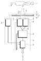
도 1은 본 발명에 따른 디스플레이장치(100)의 구조를 개략적으로 나타낸 도이다. 도 1에 나타낸 바와 같이, 디스플레이장치(100)는 영상을 처리하는 제어부(110), 전원부(120), 그래픽 유저 인터페이스(Graphic User Interface; 이하 'GUI'라 칭함) 생성부(130), 디스플레이부(140), 및 제1센서(150), 및 제2센서(160)를 포함할 수 있다. 디스플레이장치(100)는 상술한 구성요소들 외에 튜너를 포함하는 영상수신부(미도시), 수신된 영상을 처리하는 영상처리부(미도시), 유무선 통신부(미도시), 타이밍제어부(미도시), 음성처리부(미도시) 등 더 많은 구성요소들을 포함할 수 있으며, 간략한 설명을 위해 생략한다.1 is a diagram schematically showing the structure of a
제어부(110)는 디스플레이장치(100)의 각 구성요소, 예를 들면 전원부(120), GUI 생성부(130), 디스플레이부(140), 및 기타 각종 부품을 제어할 수 있다.The
제어부(110)는 각종 센서(150,160)에서 감지한 사용자의 근접 또는 이탈 감지 유무를 판독하여 제품의 전원을 사용자의 의도에 선점 분석하여 사용자가 디스플레이장치(100)를 온(On) 또는 오프(Off)하고자 리모컨이나 본체의 전원버튼 등을 이용하기 위해 근접하는 경우 본체가 미리 파워(Power) 온(ON) 또는 오프(OFF)하여 사용자가 실제 파워(Power) 온(ON) 또는 오프(OFF) 행위 시 빠르게 온(On) 또는 오프(OFF)하도록 할 수 있다.The
제어부(110)는 또한 사용자 인식 결과에 따라 또는 특정 구역의 백라이트만을 켜서, 국부적인 화면으로 사전 설정된 화면을 표시할 수 있다.The
제어부(110)는 인체감지결과에 따라 사용자를 의미하는 피사체 또는 형상을 의미하는 그래픽 유저 인터페이스(GUI)로 제시하는 형태, 예를 들면 사용자의 외곽라인기반의 일러스트레이션을 LCD화면을 통해 제공하고, 사용자가 해당 영역을 이탈하는 경우 해당 일러스트레이션도 페이드 아웃(Fade out)되는 형태로 사라지도록 영상처리부(미도시) 및 디스플레이부(140)를 제어할 수 있다. 또한, 제어부(110)는 사용자의 모습을 일정 외곽 일러스트레이션으로 표시하여 유사하게 모션 그래픽 유저 인터페이스(GUI)로 표시하도록 영상처리부(미도시) 및 디스플레이부(140)를 제어할 수 있다.The
제어부(110)는 ASICs (application specific integrated circuits), DSPs (digital signal processors), DSPDs (digital signal processing devices), PLDs (programmable logic devices), FPGAs (field programmable gate arrays), 마이크로 컨트롤러(micro-controllers), 마이크로 프로세서(microprocessors)를 포함할 수 있다.The
전원부(120)는 디스플레이장치(100)의 각 종 부품, 예를 들면 제어부(110), 디스플레이부(140), 제1 및 제2센서(150,160) 등에 전원을 공급할 수 있다.The
전원부(120)는 제어부(110)의 제어 하에 디스플레이장치(100) 본체, 또는 각 부품에 전원을 공급한다. 이때 제어부(110)는 제1 및 제2센서(150,160)의 사용자 감지 결과를 이용하여 디스플레이장치(100) 본체 또는 각 부품에 전원을 제어할 수 있다.The
전원부(120)는 디스플레이장치(100)의 전원이 오프인 경우에도 제1센서(150) 및/또는 제2센서(160)의 전원을 온 상태로 유지할 수 있다. 선택적으로, 전원부(120)는 디스플레이장치(100)의 전원이 온인 경우에 제1센서(150) 및/또는 제2센서(160)의 전원을 오프 상태로 전환할 수도 있다.The
GUI생성부(130)는 사용자 명령 입력을 위한 그래픽 유저 인터페이스(GUI)를 생성하여 디스플레이부(140)에 표시할 수 있다. GUI생성부(130)는 제1센서(150) 및/또는 제2센서(160)에 의한 사용자 감지 결과에 따라 제어부(110)에 의해 사용자가 바로 디스플레이부(140) 터치화면 또는 리모컨(미도시) 등의 입력장치를 통하여 명령을 입력하도록 GUI를 생성할 수 있다. GUI는 사용자가 디스플레이장치에 접근하는 것을 감지함에 따라 사용자의 피사체 또는 형상으로 디스플레이 패널 상에 표시된다. 표시된 GUI는 사용자가 디스플레이장치로부터 벗어난 것을 감지함에 따라 페이드 아웃된다.The
디스플레이(140)는 영상처리부(미도시) 또는 그래픽 처리부(미도시)에서 처리된 영상 또는 그래픽을 표시할 수 있다. 디스플레이부(140)의 구현 방식은 한정되지 않는 바, 액정층을 포함하는 액정패널 또는 유기물로 구성된 발광층을 포함하는 유기발광패널, 플라즈마 표시패널 등으로 구현될 수 있다.The
디스플레이부(140)는 구현 방식에 따라서 부가적인 구성을 추가적으로 포함할 수 있다. 디스플레이부(140)는 예를 들면 액정 방식인 경우, 백라이트, 편광특성 및 조명광의 집광특성에 따라서 프리즘 필름, 편광필름, LCD셀, 컬러필터 등을 포함할 수 있다.The
제1센서(150)는 무선 주파수(RF)센서를 포함할 수 있다. 무선 주파수(Radio Frequency; 이하 RF센서라 칭함)센서는 특정 주파수의 전파, 예를 들면 극초단파(microwave)를 송신한 후 해당 신호의 반사파를 감지하는 방식의 도플러효과를 적용하여 거리에 따른 주파수변화를 검출하여 감지신호를 출력한다. 도플러효과란 파가 정지된 물체에 부딪혀서 돌아오는 경우에는 송수신파가 동일한 주파수를 갖지만, 움직이는 물체에 부딪혔다가 반사되는 경우에는 주파수가 달라지는 현상이다. 송신부로 점점 가까워지는 물체의 경우 주파수가 짧아지고, 점점 멀어지는 물체의 경우 주파수가 길어진다. 따라서, 주파수의 변화와 변화상태를 분석하여 움직이는 물체가 있는지, 물체가 어느 방향으로 움직였는지, 얼마의 속도로 움직였는지 등을 분석할 수 있다. RF센서는 라디오 주파수를 사용하기 때문에 장애물을 뚫고 송수신이 가능하며, 넓은 지역으로 전파를 송신할 수 있다. 하지만 적외선 센서에 비해 비용이 많이 들고 PCB회로를 별도로 구비해야 하기 때문에 여유공간이 많이 필요하다.The
제2센서(160)는 적외선(Infrared) 감지 기반의 인체 체온 감지 센서, 예를 들면 볼로미터(bolometer)를 포함할 수 있다. 제2센서(160)는 예를 들면 리모컨 제어를 위한 IR송수신부(미도시)에 장착될 수 있다. 적외선 센서는 스스로 적외선을 복사하여 빛이 반사되어 돌아오는 회광이 차단됨으로써 변화를 검지하는 능동식과, 자체에는 발광기를 가지지 않고 외계로부터 받는 적외선의 변화만을 읽어내는 수동식이 있다. 적외선이란 전자기파스펙트럼중 가시광선의 적색광보다 길고 마이크로파보다 짧은파장, 즉파장0.75μm~1mm의 복사선을 말한다.The
제2센서(160)의 감지결과는 제1센서(150)에 전원을 온(ON)시키거나 송신 주파수를 증폭하는 트리거 데이터로 이용할 수 있다. 즉, 사용자가 없을 경우에는 디스플레이장치(100)의 전원을 완전 오프(OFF)시키고, 제1센서(150)의 전원도 완전 오프(OFF) 또는 저감도 작동시킨 상태에서, 제2센서(160)의 사용자 감지 결과를 통하여 제2센서(150)를 온(ON) 또는 증폭하고, RF센서(150)의 사용자 감지를 통하여 디스플레이장치(100)의 전원 또는 대기전원을 온(ON)시키거나 디스플레이장치(100)의 특정 기능만을 작동하도록 할 수 있다.The detection result of the
물론, 제2센서(160)는 선택적으로 적용되는 것이며, 제1센서(150)만으로도 충분히 본 발명의 사용자 인식 효과를 얻을 수 있다.Of course, the
도 2는 본 발명의 일 실시예에 따른 디스플레이장치(100)의 디스플레이부(140)를 구성하는 표시패널(200)을 나타내는 개략적 단면도이다. 표시패널(200)은 액정표시패널, 플라즈마 디스플레이 패널, 유기발광표시(LED) 패널 등이 사용될 수 있으나, 본 발명의 실시예에서는 액정표시패널을 예로 들어 설명하기로 한다,2 is a schematic cross-sectional view illustrating a
액정표시패널(200)은 전면에서부터 순서대로 제1편광필름(211), 제1투명기판(212), 블랙 매트릭스(213), 컬러필터(214), 공통전극(ITO)(215), 액정(Liquid Crystal)층(216), 박막트랜지스터(TFT)(217), 픽셀전극(218), 제2투명기판(219), 제2편광필름(220), 백라이트 도광판(221), 반사판(222) 등을 포함하여 구성할 수 있다. 공통 전극(215)은 제1투명기판(212)의 전면에 걸쳐 형성되어 있으며 공통 전압을 인가 받는다. 픽셀전극(218)과 공통 전극(215) 및 그 사이의 액정층(216)은 회로적으로 볼 때 액정 축전기를 이루며, 액정 축전기는 이에 연결된 박막트랜지스터(217)와 함께 픽셀을 이루는 기본 단위가 된다. 픽셀전극(218)과 공통 전극(215)에 전압을 인가하여 액정층(216)에 전계를 생성하고, 이 전계의 세기를 조절하여 액정층을 통과하는 빛의 투과율을 조절함으로써 원하는 화상을 얻는다.The liquid
도 3에 나타낸 바와 같이, 액정표시패널(200)의 픽셀전극(218)은 게이트선(G1-G2n), 유지전극선(S1-S2n), 데이터전극선(D1-Dm)을 포함할 수 있다. 게이트선(G1-G2n)에는 게이트 구동부(252)가 연결되고, 유지전극선(S1-S2n)에는 유지전극선 구동부(254)가 연결되고, 데이터전극선(D1-Dm)에는 데이터구동부(256)가 연결되고, 각 전극구동부(252,254,256)는 신호제어부(258)에 연결된다.As shown in FIG. 3, the pixel electrodes 218 of the liquid
게이트구동부(252)는 신호제어부(258)로부터의 게이트 제어 신호(CONT1)에 따라 게이트 온 전압을 해당 게이트선(G1-G2n)에 인가하여 게이트선(G1-G2n)에 연결된 스위칭 소자인 박막트랜지스터(217) 턴온시킨다. 그러면, 데이터선(D1-Dm)에 인가된 데이터 신호가 턴온된 박막트랜지스터(217)를 통하여 해당 픽셀(PX)에 인가된다.The
유지 전극선 구동부(254)는 외부로부터의 제어 신호(VB, VA1, VA2)에 기초하여, 해당 크기의 레벨을 갖는 유지전압을 유지 전극선(S1-S2n)에 차례로 인가하여, 픽셀전극(218)에 인가된 전압, 즉 화소 전극 전압을 변화시킨다.The sustain
신호 제어부(600)는 입력 영상 신호(R, G, B)와 입력 제어 신호를 기초로 입력 영상 신호(R, G, B)를 액정 표시패널(200)의 동작 조건에 맞게 적절히 처리하고, 게이트 제어 신호(CONT1) 및 데이터 제어 신호(CONT2) 등을 생성한 후, 게이트 제어 신호(CONT1)를 게이트구동부(252)로 내보내고 데이터 제어 신호(CONT2)와 처리한 영상 신호(DAT)를 데이터 구동부(256)로 내보낸다. 신호제어부(258)로부터의 데이터 제어 신호(CONT2)에 따라, 데이터구동부(256)는 한 행의 픽셀(PX)에 대한 디지털 영상 신호(DAT)를 수신하고, 각 디지털 영상 신호(DAT)에 대응하는 계조 전압을 선택함으로써 디지털 영상 신호(DAT)를 아날로그 데이터 신호로 변환한 다음, 이를 해당 데이터선(D1-Dm)에 인가하여 영상을 표시한다.The signal control unit 600 properly processes the input image signals R, G, and B according to the operating conditions of the liquid
상술한 액정표시패널(200)의 후방, 즉 반사판(222)의 후방에는 예를 들면 금속성으로 지지프레임(230)이 배치되어 액정표시패널을 지지할 수 있다. 또한, 지지프레임(230)은 RF센서(150) 및 액정표시패널(200)의 구동회로, 예를 들면 PCB형태의 영상보드(미도시), 그래픽보드(미도시), XY전극 드라이버 등이 고정 지지될 수 있다. 지지프레임(230)의 후방에는 소정 간격을 두고 후면 커버(240)가 결합될 수 있다.A
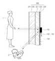
도 4는 본 발명의 일 실시예에 따른 디스플레이장치에 RF센서의 설치방법을 나타내는 개략도이다.4 is a schematic diagram showing a method of installing an RF sensor in a display device according to an embodiment of the present invention.
RF센서(150)는 액정표시패널(200)의 전면에서 보이지 않도록 지지프레임(230)에 일체형 또는 분리형으로 장착될 수 있다. 특히, 지지프레임(230)은 알루미늄, 철, 스테인리스 등의 금속성 재료로 제작되는 것이 일반적이므로, 무선 주파수 감지신호 통과를 용이하게 하기 위해 관통공(232)을 형성한 후, 관통공(232) 내에 RF센서(150)를 적어도 부분적으로 삽입하여 설치할 수 있다. 이때, 지지프레임(230)의 관통공(232)은 그 크기를 최소화하기 위해 RF센서(150)의 RF송수신부(152)만을 삽입할 수 있을 정도로 형성하는 것이 바람직하다. 상기 지지프레임(230)의 관통공(232)으로 전방의 백라이트 광이 누설되지 않도록 삽입된 RF송수신부(152)의 표면을 광누설방지 코팅(coating) 또는 (shielding)하는 것도 좋다.The
물론 지지프레임(230)이 무선 주파수가 투과할 수 있는 재료로 제작될 경우 관통공(232)을 설치하지 않아도 무방하다.Of course, if the
결과적으로 RF센서(150)에서 발산된 무선 주파수 감지신호는 관통공(232)을 통과 한 후, 전면의 액정표시패널(200)를 투과하여 액정표시패널 (200) 전방으로 방출된다. 이때, 액정표시패널 전방의 물체, 예를 들면 사용자(1)나 애완견(2)에 부딪혀 반사되는 반사파는 다시 액정표시패널(200) 및 관통공(232)에 설치된 수신부를 통하여 수신된다.As a result, the radio frequency detection signal emitted from the
RF센서(150)는 RF송수신부(152), RF센서모듈(154) 및 RF송수신부(152)와 RF센서모듈(154)를 연결하는 연결선(156)을 포함하여 구성할 수 있다.The
도 5는 본 발명에 따른 RF센서(150)와 적외선센서(160)의 구성을 나타낸 블록도이다.5 is a block diagram showing the configuration of the
RF송수신부(152)는 무선 주파수 감지신호를 발산하는 RF발산 안테나(152-1)와 대상에서 반사된 반사파를 수신하는 RF수신 안테나(152-2)를 포함할 수 있다.The RF transmitter/
RF송수신부(152)는 연결선(156)을 통하여 RF센서모듈(154)에 연결될 수 있다.The RF transmitter/
RF센서모듈(154)은 RF송수신부(152)가 발산하는 무선 주파수를 생성하고 수신된 반사파를 처리하는 후처리부(153) 및 센서 제어부(155)를 포함할 수 있다.The
후처리부(153)는 증폭기(AMP), 공진기(resonator), 필터, 아날로그 디지털 변환기(ADC), FET(field effect transistor), MMIC(Monolithic Microwave Integrated Circuit) 등을 포함할 수 있다.The
센서 제어부(155)는 제품, 예를 들면 디스플레이장치(100)의 제어부(110)로부터 명령이나 데이터를 수신하여 처리하거나, 상기 후처리부(153)에서 보내는 신호를 처리하여 분석 처리하여 디스플레이장치(100)의 제어부(110)로 전송하는 역할을 한다. 센서 제어부(155)는 마이크로 프로세서(MCU), USB 인터페이스, I2C 인터페이스 등을 포함할 수 있다.The
적외선센서(160)는 사용자의 근접 또는 이탈 감지 유무를 판독하여 제품의 전원(Power)을 사용자의 의도를 선점 분석하여 빠르게 온 또는 오프하도록 하기 위한 별종 트리거 기능을 제공할 수 있다.The
도 6은 본 발명의 다른 실시예에 따른 RF센서 모듈의 구성을 나타내는 블록도이다.6 is a block diagram showing the configuration of an RF sensor module according to another embodiment of the present invention.
본 발명에 따른 사용자 감지를 위한 무선 주파수 신호는 액정표시패널(200)를 투과하여 송신되고 수신된다. 그러나, 액정표시패널(200)에는 공통전극(215), 픽셀전극(218), 박막트랜지스터(TFT)(217) 등 무선 주파수 신호 투과를 방해하거나 액정표시패널 동작에 따라 발생하는 신호 주파수가 송수신되는 반사파에 혼합될 가능성이 높기 때문에 RF수신 안테나(152-2)와 후처리부(153) 사이에 저잡음 증폭기(Low Noise Amplifier)(156)를 부가하는 것이 바람직하다.The radio frequency signal for user detection according to the present invention is transmitted and received through the liquid
이하 본 발명에 따른 디스플레이장치(100)의 사용자 감지방법을 도 7을 참조하여 설명하면 다음과 같다.Hereinafter, a method for detecting a user of the
단계 S110에서, RF송신안테나(152-1)를 통해 예를 들면 10GHz or 24GHz or 66GHz, 77GHz 주파수를 표시패널(200)의 전방으로 방출한다.In step S110, frequencies of, for example, 10 GHz, 24 GHz, 66 GHz, and 77 GHz are emitted to the front of the
단계 S120에서, 상기 방출한 주파수가 전방의 대상(1, 2)에 부딪혀 반사되는 반사파를 RF수신 안테나(152-2)를 통해 수신한다. RF수신 안테나(152-2)에서 감지된 신호는 대단히 미약하기에 저잡음 증폭기(LNA)(156)를 거쳐 증폭되어 후처리부(153)에 전달된다. In step S120, a reflected wave reflected by the emitted frequency hitting the
이때, 단계 S110-S120단계를 원활하게 하기 위해 액정표시패널(200)을 동작시키는 매커니즘에 따라 적절한 알고리즘으로 무선 주파수 감지신호를 송신하여야 한다. 왜냐하면도 2에 나타낸 바와 같이, 액정표시패널(200)은 각종 배선을 위한 ITO(Indium Tin Oxide)에 의한 투명한 전기 전도체가 분포되어 실제 전파환경을 블록킹하기 때문에 실질적으로 액정표시패널(200)을 투과하여 전파가 나갔다가 되돌아오는 것을 감지하는 것은 매우 어려운 상태이다.At this time, in order to facilitate steps S110-S120, a radio frequency detection signal must be transmitted with an appropriate algorithm according to a mechanism for operating the liquid
또한, 무선 주파수 신호는 예를 들면 10GHz or 24GHz or 66GHz, 77GHz 정도 매우 짧은 파장을 갖기 때문에 액정층의 액정(LC) 분자에 방해를 받을 수 있다. 따라서 RF주파수 신호는 액정표시패널(200)의 액정(LC)의 뒤틀림 각도를 전파투과율이 최대상태에 있을 때 주기적으로 발산하는 것이 바람직하다. 액정표시패널(200)의 액정(LC)은 픽셀전극(218)에 전압을 인가하여 액정(LC)의 뒤틀림 각을 변화시켜 영상을 표시할 수 있다. 이때, 영상을 표시하기 위해 액정(LC)의 뒤틀림 제어는 도 3에 나타낸 신호제어부(258)가 입력영상신호(R, G, B)를 처리하여 영상신호(DAT)를 데이터구동부(256)에 공급하고, 유지전극선구동부(254)가 외부로부터의 제어신호(VB, VA1, VA2)에 기초하여 유지전압을 유지전극선(S1-S2n)에 인가함으로써 달성될 수 있다.In addition, since the radio frequency signal has a very short wavelength, for example, about 10GHz, 24GHz, 66GHz, or 77GHz, it may be disturbed by liquid crystal (LC) molecules in the liquid crystal layer. Therefore, it is preferable that the RF frequency signal periodically emit the twist angle of the liquid crystal (LC) of the liquid
따라서, 액정(LC)의 뒤틀림 각도는 액정표시패널(200)의 액정층(LC)이 광이 완전히 통과할 수 있는 상태일 때 전파투과율이 최대인 상태가 될 수 있다. 따라서, RF센서(150)는 신호제어부(258), 데이터 구동부(256), 유지전극선 구동부(254) 중 적어도 하나의 영상신호 표시 동작에 동기화하여 주기적으로 무선주파수 신호를 발산하는 것이 액정층(LC)에 의한 무선주파수 차단을 방지할 수 있다. 즉, RF센서(150)는 신호제어부(258)와 데이터 구동부(256), 유지전극선 구동부(254)의 동작에 동기화하여 액정의 뒤틀림 각도를 일정주기, 즉 240Hz, 120Hz, 60Hz 형태의 액정동작주기, 화면교차주기에 맞추어 주기적으로 발산할 수 있다.Accordingly, the distortion angle of the liquid crystal LC may be a state in which the radio wave transmittance is maximized when the liquid crystal layer LC of the liquid
단계 130에서, 센서 제어부(155)는 반사파로부터 감지된 대상이 소정 거리 내에 있거나 소정 주파수 범위 내에 있을 때 사용자로 판단한다. 만일 감지 대상이 사전 설정 된 거리 밖에 있거나 사전 설정된 소정 주파수 범위를 벗어날 경우에는 사용자로 판단하지 않을 수 있다. 사용자(1)외에 일정 반사파 기준 범위를 벗어나는 RF수신이 이루어지는 경우, 사용자가 아닌 대상(2), 예를 들면 애완견 또는 장난감으로 판단하여 감지의 대상에서 제외하도록 할 수 있다. 또한, 잦은 근거리 감지가 많이 되는 경우는 후처리부(153)의 MMIC 및 FET를 저출력으로 조정하거나 저잡음 증폭기(156)의 이득(Gain)을 저감화하여 전체 동작되는 소비전력을 절감할 수도 있다. 또한, 원거리 감지가 소정시간 동안 반복되는 경우 후처리부(153)의 MMIC 및 FET를 저출력으로 조정하거나 저잡음 증폭기(156)의 이득(Gain)을 저감화하여 전체 동작되는 소비전력을 절감할 수도 있다.In
단계 130에서 사용자 인식 결과를 디스플레이장치(100)의 제어부(110)에 전송하면, 단계 S140에서, 제어부(110)는 전원부(120)를 제어하여 디스플레이장치(100)의 특정 기능, 예를 들면 본체 전원을 켜거나 대기전원만을 온 시킬 수 있다. 또한, 디스플레이장치(100)의 제어부(110)는 백라이트의 일부만을 켜서, 화면의 일부만을 표시하여 정보를 제공할 수도 있다. 결과적으로, 감지결과를 기본으로 사용자의 근접 또는 이탈을 판독하고, 디스플레이장치(100)의 전원을 사용자의 의도에 대한 선점 분석하여 사용자가 디스플레이장치(100)를 온(ON) 또는 오프(OFF) 하고자 리모컨이나 본체의 전원버튼 등을 이용하기 위해 근접하는 경우에 대해 미리 파워 온(Power on)하여 사용자가 실제 파워 온(Poweron) 행위 시 빠르게 온 또는 오프(OFF) 하도록 사전 구동 기능을 제공하는 것이 가능하다. 또한 제어부(110)는 사용자가 다른 파워오프(Power Off)행위를 하지 않고 지정 감지영역을 이탈하여 일정시간이 지나는 경우는일정시간 후까지 지정된 범위 내의 재 근접여부를 감시하여 디스플레이장치(100)의 본체 전원을 오프(OFF) 할 수 있다.When the user recognition result is transmitted to the
단계 130에서, 사용자 인식 결과를 디스플레이장치(100)의 제어부(110)에 전송하면, 제어부(110)는 사용자의 근접 또는 이탈의 여부를 사용자를 의미하는 피사체 또는 형상을 의미하는 그래픽 유저 인터페이스(GUI)로 표시할 수 있다. 예를 들면 제어부(110)는 수신되는 사용자 인식 데이터를 이용하여 사용자의 외곽라인 기반의 일러스트레이션을 표시패널(200)을 통해 제공하고, 사용자가 해당영역을 이탈하는 경우 해당 일러스트레이션도 페이드 아웃(Fade out)되도록 할 수 있다. 또한, 제어부(110)는 수신되는 인식 데이터를 이용하여 사용자의 모습을 일정 외곽 일러스트레이션으로 표시하여 유사하게 모션그래픽 유저 인터페이스(GUI)로 표시할 수 있다.In
단계 S150에서, 사용자 또는 제어부(110)가 디스플레이장치(100) 본체의 전원을 오프(OFF) 시키는 명령을 있는 경우, RF센서(150) 또는 적외선 센서(160)의 전원을 온(ON)시킬 수 있다. 물론, 이는 디스플레이장치(100)의 전원이 온 될 때 RF센서(150) 또는 적외선센서(160)를 오프(OFF)시킨 경우에 한다.In step S150, when the user or the
본 발명에 따른 적외선 센서(160)의 추가는 표시패널(200)이 장착된 제품, 예를 들면 디스플레이장치(100), 자동판매기(미도시), 고객안내장치(미도시) 등의 파워 오프(Power Off) 상태에서 대상을 우선 감지하기 위한 것이다. 적외선 센서(160)의 감지 결과를 기초로 일정 수준의 감지기준에 부합되는 경우, RF센서(150)의 전원을 온 시키거나, RF송신기의 파워를 후처리부(153)에 포함된 FET와 MMIC를 이용하여 강제적으로 증폭시켜서 감지를 위한 전파 투과율을 높일 수 있다.The addition of the
상기한 실시예는 예시적인 것에 불과한 것으로, 당해 기술 분야의 통상의 지식을 가진 자라면 다양한 변형 및 균등한 타 실시예가 가능하다. 따라서, 본 발명의 진정한 기술적 보호범위는 하기의 특허청구범위에 기재된 발명의 기술적 사상에 의해 정해져야 할 것이다.The above-described embodiments are merely exemplary, and various modifications and equivalent other embodiments are possible for those of ordinary skill in the art. Therefore, the true technical protection scope of the present invention should be determined by the technical idea of the invention described in the following claims.
100: 디스플레이장치
110: 제어부
120: 전원부
130: GUI생성부
140: 디스플레이부
150: 제1센서(RF)
160: 제2센서(적외선)
200: 표시패널
230: 지지프레임100: display device
110: control unit
120: power supply
130: GUI generation unit
140: display unit
150: first sensor (RF)
160: second sensor (infrared)
200: display panel
230: support frame
Claims (35)
Translated fromKorean표시패널;
상기 표시패널의 후방에 위치하는 지지프레임;
상기 표시패널을 향하여 무선 신호를 송신하도록 상기 지지프레임에 마련되는 통신부; 및
상기 표시패널에 대한 상기 무선 신호의 투과율을 식별하고,
상기 식별된 투과율이 소정치 이상인 것에 대응하여 상기 무선 신호를 송신하도록 상기 통신부를 제어하고,
상기 송신된 무선 신호에 대응하여 상기 통신부에 의해 수신되는 무선 신호에 기초하여 상기 표시패널의 전방에 있는 물체에 대응하는 기능을 수행하는 제어부
를 포함하는 디스플레이장치.In the display device,
Display panel;
A support frame positioned behind the display panel;
A communication unit provided in the support frame to transmit a radio signal toward the display panel; And
Identifying the transmittance of the radio signal to the display panel,
Controlling the communication unit to transmit the radio signal in response to the identified transmittance being equal to or greater than a predetermined value,
A control unit performing a function corresponding to an object in front of the display panel based on a radio signal received by the communication unit in response to the transmitted radio signal
Display device comprising a.
상기 지지프레임은 상기 무선 신호를 송수신할 수 있는 관통부를 포함하는 디스플레이장치.The method of claim 1,
The support frame is a display device including a through portion capable of transmitting and receiving the radio signal.
상기 통신부는 RF송수신부를 더 포함하며,
상기 RF송수신부는 상기 관통부 내에 적어도 부분적으로 수용되는 디스플레이장치.The method of claim 2,
The communication unit further includes an RF transmission and reception unit,
The display device at least partially accommodated in the RF transmitting and receiving unit in the through portion.
상기 RF송수신부는 광누출방지 재료로 코팅(coating) 또는 실딩(shielding)되는 디스플레이장치.The method of claim 3,
A display device in which the RF transmission and reception unit is coated or shielded with a light leakage preventing material.
상기 통신부는 저잡음증폭부(LNA)를 포함하는 디스플레이장치.The method of claim 1,
The communication unit display device including a low noise amplifier (LNA).
상기 통신부는 적외선센서를 더 포함하는 디스플레이장치.The method of claim 3,
The display device further comprises an infrared sensor in the communication unit.
상기 제어부는, 상기 적외선센서의 감지 결과를 이용하여 상기 RF송수신부의 전원을 온(ON)시키거나 상기 RF송수신부의 송신 주파수를 증폭하는 디스플레이장치.The method of claim 6,
The control unit is a display device for amplifying a transmission frequency of the RF transmitting and receiving unit or turning on the power of the RF transmitting and receiving unit by using the detection result of the infrared sensor.
상기 제어부는, 상기 수신되는 무선 신호에 기초하여 사용자가 감지되거나 소정거리 범위 내에 상기 사용자의 위치가 감지되면, 상기 디스플레이장치에 전원을 온(ON)시키는 디스플레이장치.The method of claim 1,
The controller is a display device that turns on power to the display device when a user is sensed based on the received wireless signal or a location of the user within a predetermined distance range is sensed.
상기 제어부는, 상기 디스플레이장치에 전원을 온(ON) 시킨 후에, 상기 RF송수신부의 전원을 오프(OFF)시키는 디스플레이장치.The method of claim 7,
The control unit, after turning on the power of the display device, the display device to turn off the power of the RF transmitting and receiving unit (OFF).
상기 제어부는, 상기 수신되는 무선 신호에 기초하여 사용자가 감지되지 않거나 소정거리 범위 밖에 상기 사용자의 위치가 감지되면, 상기 디스플레이장치의 전원을 오프(OFF)시키는 디스플레이장치.The method of claim 1,
The control unit turns off the power of the display device when a user is not detected or a location of the user outside a predetermined distance range is detected based on the received wireless signal.
상기 제어부는, 상기 수신되는 무선 신호에 기초하여 사용자가 감지되거나 소정거리 범위 내에 상기 사용자의 위치가 감지되면, 상기 디스플레이장치의 특정 기능만을 온(ON)시키는 디스플레이장치.The method of claim 1,
The control unit, when a user is sensed based on the received wireless signal or a location of the user within a predetermined distance range, turns on only a specific function of the display device.
상기 특정 기능은 상기 디스플레이장치의 대기전원을 온(ON)시키는 것인 디스플레이장치.The method of claim 11,
The specific function is to turn on the standby power of the display device.
상기 특정 기능은 상기 디스플레이장치의 백라이트 일부를 동작시켜, 국부적 표시패널에 정보를 표시하는 것인 디스플레이장치.The method of claim 11,
The specific function is to display information on a local display panel by operating a part of a backlight of the display device.
상기 제어부는,
사용자의 근접을 감지함에 따라 상기 사용자를 나타내는 피사체 또는 형상을 포함하는 그래픽유저인터페이스(GUI)를 상기 표시패널에 표시하고,
상기 사용자의 이탈을 감지함에 따라 상기 표시된 그래픽유저인터페이스를 페이드 아웃(fade out)시키도록 상기 표시패널을 제어하는 디스플레이장치.The method of claim 1,
The control unit,
As the proximity of the user is detected, a graphic user interface (GUI) including a subject or shape representing the user is displayed on the display panel,
A display device that controls the display panel to fade out the displayed graphic user interface upon detecting the user's departure.
상기 제어부는, 사용자의 근접을 감지함에 따라 상기 사용자의 모습을 외곽 일러스트레이션의 모션 그래픽유저인터페이스로 표시하는 디스플레이장치.The method of claim 1,
The controller displays the user's appearance as a motion graphic user interface of an outer illustration as it detects the proximity of the user.
상기 통신부는 상기 지지프레임에 일체형 또는 분리형으로 부착되는 디스플레이장치.The method of claim 1,
The communication unit is a display device integrally or detachably attached to the support frame.
상기 표시패널은 액정표시패널을 포함하며,
상기 디스플레이장치는 상기 액정표시패널에 영상을 표시하기 위한 패널구동부를 포함하며,
상기 제어부는, 상기 디스플레이장치의 전원을 온(ON)시켰을 때, 상기 액정표시패널의 액정 뒤틀림 각도가 광 통과 가능 상태를 유지하는 상기 패널구동부의 영상표시 타이밍과 동기화시켜 주기적으로 상기 무선 신호를 송신하는 디스플레이장치.The method of claim 1,
The display panel includes a liquid crystal display panel,
The display device includes a panel driving unit for displaying an image on the liquid crystal display panel,
When the power of the display device is turned on, the control unit periodically transmits the wireless signal by synchronizing the liquid crystal distortion angle of the liquid crystal display panel with the image display timing of the panel driving unit maintaining a light-passable state. Display device.
상기 주기는 액정동작주기 또는 화면교차주기를 포함하는 디스플레이장치.The method of claim 17,
The period is a display device including a liquid crystal operation period or a screen crossing period.
상기 제어부는, 근거리 감지 또는 원거리 감지가 소정 시간 동안 반복되는 경우 상기 무선 신호의 송신 출력을 낮추는 디스플레이장치.The method of claim 1,
The controller is a display device that lowers the transmission power of the wireless signal when the short-range detection or the long-range detection is repeated for a predetermined time.
상기 제어부는, 상기 수신되는 무선 신호의 주파수범위가 소정 범위를 벗어나는 경우 감지에러로 판단하는 디스플레이장치.The method of claim 1,
The control unit, a display device that determines as a detection error when the frequency range of the received radio signal is out of a predetermined range.
상기 표시패널에 대한 상기 무선 신호의 투과율을 식별하는 단계;
상기 식별된 투과율이 소정치 이상인 것에 대응하여 상기 무선 신호를 송신하는 단계; 및
상기 송신된 무선 신호에 대응하여 상기 통신부에 의해 수신되는 무선 신호에 기초하여 상기 표시패널의 전방에 있는 물체에 대응하는 기능을 수행하는 단계
를 포함하는 제어방법.A method for controlling a display apparatus comprising a display panel, a support frame positioned behind the display panel, and a communication unit provided on the support frame to transmit a radio signal toward the display panel,
Identifying a transmittance of the radio signal to the display panel;
Transmitting the radio signal in response to the identified transmittance being equal to or greater than a predetermined value; And
Performing a function corresponding to an object in front of the display panel based on a radio signal received by the communication unit in response to the transmitted radio signal
Control method comprising a.
상기 수신된 무선 신호의 저잡음을 증폭하는 단계를 더 포함하는 제어방법.The method of claim 21,
A control method further comprising the step of amplifying the low noise of the received radio signal.
상기 무선 신호를 송신하는 단계는, 적외선센서를 통하여 적외선 신호를 송신하는 단계를 더 포함하는 제어방법.The method of claim 21,
The transmitting of the wireless signal further comprises transmitting an infrared signal through an infrared sensor.
상기 기능을 수행하는 단계는, 상기 송신된 적외선 신호에 대응하여 수신되는 적외선 신호에 기초하여 RF송수신부의 전원을 온(ON)시키거나 상기 RF송수신부의 송신 주파수를 증폭하는 단계를 더 포함하는 제어방법.The method of claim 23,
The performing of the function further comprises turning on the power of the RF transceiver or amplifying the transmission frequency of the RF transceiver based on the infrared signal received in response to the transmitted infrared signal. .
상기 기능을 수행하는 단계는, 상기 수신되는 무선 신호에 기초하여 사용자가 감지되거나 소정거리 범위 내에 상기 사용자의 위치가 감지되면, 상기 디스플레이장치에 전원을 온(ON)시키는 단계를 더 포함하는 제어방법.The method of claim 21,
The performing of the function further includes turning on power to the display device when a user is sensed based on the received wireless signal or a location of the user within a predetermined distance range is sensed. .
상기 기능을 수행하는 단계는, 상기 수신되는 무선 신호에 기초하여 사용자가 감지되지 않거나 소정거리 범위 밖에 상기 사용자의 위치가 감지되면, 상기 디스플레이장치의 전원을 오프(OFF)시키는 단계를 더 포함하는 제어방법.The method of claim 21,
The performing of the function may further include turning off the power of the display device when a user is not detected or a location of the user outside a predetermined distance range is detected based on the received wireless signal. Way.
상기 기능을 수행하는 단계는, 상기 수신되는 무선 신호에 기초하여 사용자가 감지되거나 소정거리 범위 내에 상기 사용자의 위치가 감지되면 상기 디스플레이장치의 특정 기능만을 온(ON)시키는 단계를 더 포함하는 제어방법.The method of claim 21,
The performing of the function further comprises turning ON only a specific function of the display device when a user is sensed based on the received wireless signal or a location of the user within a predetermined distance range is detected. .
상기 특정 기능은 상기 디스플레이장치의 대기전원을 온(ON)시키는 것인 제어방법.The method of claim 27,
The specific function is to turn on the standby power of the display device.
상기 특정 기능은 상기 디스플레이장치의 백라이트 일부를 동작시켜, 국부적 표시패널에 정보를 표시하는 것인 제어방법.The method of claim 27,
The specific function is to display information on a local display panel by operating a part of the backlight of the display device.
상기 기능을 수행하는 단계는,
사용자의 근접을 감지함에 따라 상기 사용자를 나타내는 피사체 또는 형상을 포함하는 그래픽유저인터페이스(GUI)를 표시하는 단계; 및
상기 사용자의 이탈을 감지함에 따라 상기 표시된 그래픽유저인터페이스를 페이드 아웃(fade out)시키는 단계를 포함하는 제어방법.The method of claim 21,
The step of performing the function,
Displaying a graphic user interface (GUI) including a subject or shape representing the user as the proximity of the user is sensed; And
And fading out the displayed graphic user interface upon detecting the departure of the user.
상기 기능을 수행하는 단계는, 사용자의 근접을 감지함에 따라 상기 사용자의 모습을 외곽 일러스트레이션의 모션 그래픽유저인터페이스로 표시하는 단계를 포함하는 제어방법.The method of claim 21,
The performing of the function includes the step of displaying the user's appearance as a motion graphic user interface of an outer illustration as the proximity of the user is detected.
상기 표시패널은 액정표시패널을 포함하며,
상기 디스플레이장치는 상기 액정표시패널에 영상을 표시하기 위한 패널구동부를 포함하며,
상기 무선 신호를 송신하는 단계는, 상기 디스플레이장치의 전원을 온(ON)시켰을 때, 상기 액정표시패널의 액정 뒤틀림 각도가 광 통과 가능 상태를 유지하는 상기 패널구동부의 영상표시 타이밍과 동기화시켜 주기적으로 상기 무선 신호를 송신하는 단계를 포함하는 제어방법.The method of claim 21,
The display panel includes a liquid crystal display panel,
The display device includes a panel driving unit for displaying an image on the liquid crystal display panel,
In the transmitting of the wireless signal, when the power of the display device is turned on, the liquid crystal distortion angle of the liquid crystal display panel is periodically synchronized with the image display timing of the panel driver to maintain a light-passing state And transmitting the radio signal.
상기 주기는 액정동작주기 또는 화면교차주기를 포함하는 제어방법.The method of claim 32,
The period is a control method including a liquid crystal operation period or a screen crossing period.
상기 무선 신호를 송신하는 단계는, 근거리 감지 또는 원거리 감지가 소정 시간 동안 반복되는 경우 상기 무선 신호의 송신 출력을 낮추는 단계를 더 포함하는 제어방법.The method of claim 21,
The transmitting of the wireless signal further comprises lowering the transmission power of the wireless signal when the short-range detection or the long-range detection is repeated for a predetermined time.
상기 기능을 수행하는 단계는, 상기 수신되는 무선 신호의 주파수가 소정 범위를 벗어나는 경우 감지에러로 판단하는 단계를 더 포함하는 제어방법.The method of claim 21,
The performing of the function further comprises determining a detection error when a frequency of the received radio signal is out of a predetermined range.
Priority Applications (2)
| Application Number | Priority Date | Filing Date | Title |
|---|---|---|---|
| KR1020140107962AKR102214194B1 (en) | 2014-08-19 | 2014-08-19 | A display device having rf sensor and method for detecting a user of the display device |
| US14/807,453US9797999B2 (en) | 2014-08-19 | 2015-07-23 | Display apparatus with RF sensor and user detection method using RF sensor |
Applications Claiming Priority (1)
| Application Number | Priority Date | Filing Date | Title |
|---|---|---|---|
| KR1020140107962AKR102214194B1 (en) | 2014-08-19 | 2014-08-19 | A display device having rf sensor and method for detecting a user of the display device |
Publications (2)
| Publication Number | Publication Date |
|---|---|
| KR20160022162A KR20160022162A (en) | 2016-02-29 |
| KR102214194B1true KR102214194B1 (en) | 2021-02-09 |
Family
ID=55348155
Family Applications (1)
| Application Number | Title | Priority Date | Filing Date |
|---|---|---|---|
| KR1020140107962AExpired - Fee RelatedKR102214194B1 (en) | 2014-08-19 | 2014-08-19 | A display device having rf sensor and method for detecting a user of the display device |
Country Status (2)
| Country | Link |
|---|---|
| US (1) | US9797999B2 (en) |
| KR (1) | KR102214194B1 (en) |
Families Citing this family (18)
| Publication number | Priority date | Publication date | Assignee | Title |
|---|---|---|---|---|
| US10142935B2 (en)* | 2016-01-26 | 2018-11-27 | Qualcomm Incorporated | Autonomous receive (RX) detector for a radio module |
| US9824589B1 (en)* | 2016-09-15 | 2017-11-21 | Ford Global Technologies, Llc | Vehicle collision risk detection |
| US10845477B2 (en) | 2017-05-10 | 2020-11-24 | Google Llc | Power management using a low-power radar |
| US10754005B2 (en) | 2017-05-31 | 2020-08-25 | Google Llc | Radar modulation for radar sensing using a wireless communication chipset |
| US10782390B2 (en) | 2017-05-31 | 2020-09-22 | Google Llc | Full-duplex operation for radar sensing using wireless communication chipset |
| US10795009B2 (en) | 2017-05-31 | 2020-10-06 | Google Llc | Digital beamforming for radar sensing using wireless communication chipset |
| KR102393933B1 (en) | 2018-08-30 | 2022-05-04 | 삼성전자주식회사 | Display apparatus and method for controlling thereof |
| BR112021019115A2 (en) | 2019-05-20 | 2021-11-30 | Google Llc | Mobile device based radar system to provide a multi-mode interface and method for the same |
| CN113632046A (en) | 2019-06-17 | 2021-11-09 | 谷歌有限责任公司 | Mobile device-based radar system for applying different power modes to a multimodal interface |
| EP3767325A1 (en)* | 2019-07-19 | 2021-01-20 | Aptiv Technologies Limited | Methods and systems for processing radar reflections |
| US11662695B2 (en)* | 2019-10-11 | 2023-05-30 | Dell Products L.P. | Information handling system infrared proximity detection with distance reduction detection |
| US11513813B2 (en) | 2020-01-31 | 2022-11-29 | Dell Products L.P. | Information handling system notification presentation based upon user presence detection |
| US11663343B2 (en) | 2020-01-31 | 2023-05-30 | Dell Products L.P. | Information handling system adaptive user presence detection |
| US12392881B2 (en)* | 2020-02-05 | 2025-08-19 | Samsung Electronics Co., Ltd. | System and method for detecting proximity of users |
| US11394417B1 (en)* | 2021-07-14 | 2022-07-19 | Qualcomm Incorporated | Human proximity sensor using short-range radar |
| WO2023038169A1 (en)* | 2021-09-09 | 2023-03-16 | 엘지전자 주식회사 | A/v transmission apparatus and a/v reception apparatus |
| CN117321485A (en)* | 2022-03-30 | 2023-12-29 | 京东方科技集团股份有限公司 | Display device and electronic apparatus |
| TWI834334B (en)* | 2022-10-12 | 2024-03-01 | 瑞軒科技股份有限公司 | Operation method for video conference system and related video conference system |
Citations (5)
| Publication number | Priority date | Publication date | Assignee | Title |
|---|---|---|---|---|
| US20060166681A1 (en)* | 2002-08-09 | 2006-07-27 | Andrew Lohbihler | Method and apparatus for position sensing |
| US20110304632A1 (en)* | 2010-06-11 | 2011-12-15 | Microsoft Corporation | Interacting with user interface via avatar |
| US20120280900A1 (en)* | 2011-05-06 | 2012-11-08 | Nokia Corporation | Gesture recognition using plural sensors |
| JP2013145463A (en)* | 2012-01-13 | 2013-07-25 | Sony Corp | Information processing apparatus and information processing method, and computer program |
| US20140213178A1 (en)* | 2013-01-31 | 2014-07-31 | Hewlett-Packard Development Company, Lp | Display Panel for Front-Side Wireless Communication |
Family Cites Families (20)
| Publication number | Priority date | Publication date | Assignee | Title |
|---|---|---|---|---|
| DE4013049A1 (en) | 1989-04-25 | 1990-10-31 | Siemens Ag | Doppler radar module circuit for object motion detection - has aerial coupled to control circuit for circuit of single active switching element for oscillator and receiver |
| US7199749B2 (en) | 2003-12-12 | 2007-04-03 | Georgia Tech Research Corporation | Radar detection device employing a scanning antenna system |
| US9898675B2 (en)* | 2009-05-01 | 2018-02-20 | Microsoft Technology Licensing, Llc | User movement tracking feedback to improve tracking |
| US20100306685A1 (en)* | 2009-05-29 | 2010-12-02 | Microsoft Corporation | User movement feedback via on-screen avatars |
| US8934937B1 (en)* | 2010-01-22 | 2015-01-13 | Amazon Technologies, Inc. | Using sensors to trigger transmit power management |
| TW201205042A (en)* | 2010-07-23 | 2012-02-01 | Capella Microsystems Corp | Electronic apparatus, proximity sensor and control method thereof |
| KR20120032888A (en)* | 2010-09-29 | 2012-04-06 | 삼성전자주식회사 | Method and apparatus for reducing power consumption of mobile device |
| KR101705549B1 (en)* | 2010-10-25 | 2017-02-23 | 삼성디스플레이 주식회사 | Display device and wireless transceiver system of image signal including the same |
| KR101932688B1 (en)* | 2010-11-29 | 2018-12-28 | 삼성전자주식회사 | Portable Device and Method for Providing User Interface Mode thereof |
| KR101890135B1 (en)* | 2011-03-18 | 2018-08-23 | 삼성전자주식회사 | Method and display apparatus for providing graphic user interface to decrease image sticking |
| KR101917685B1 (en)* | 2012-03-21 | 2018-11-13 | 엘지전자 주식회사 | Mobile terminal and control method thereof |
| US9173086B2 (en)* | 2012-07-17 | 2015-10-27 | Samsung Electronics Co., Ltd. | Method and apparatus for preventing screen off during automatic response system service in electronic device |
| KR101910509B1 (en)* | 2012-07-17 | 2018-10-22 | 삼성전자주식회사 | Method and apparatus for preventing screen off during automatic response system service in electronic device |
| US8798695B1 (en)* | 2012-09-17 | 2014-08-05 | Amazon Technologies, Inc. | Proximity sensor using antennas of a user device |
| US20140298672A1 (en)* | 2012-09-27 | 2014-10-09 | Analog Devices Technology | Locking and unlocking of contacless gesture-based user interface of device having contactless gesture detection system |
| US9152211B2 (en)* | 2012-10-30 | 2015-10-06 | Google Technology Holdings LLC | Electronic device with enhanced notifications |
| KR102070174B1 (en)* | 2013-05-16 | 2020-01-29 | 인텔 코포레이션 | Automatically adjusting display areas to reduce power consumption |
| US9322908B2 (en)* | 2013-12-23 | 2016-04-26 | Elwha Llc | Systems and methods for concealed radar imaging |
| US9798378B2 (en)* | 2014-03-31 | 2017-10-24 | Google Technology Holdings LLC | Apparatus and method for awakening a primary processor out of sleep mode |
| US9715619B2 (en)* | 2015-03-14 | 2017-07-25 | Microsoft Technology Licensing, Llc | Facilitating aligning a user and camera for user authentication |
- 2014
- 2014-08-19KRKR1020140107962Apatent/KR102214194B1/ennot_activeExpired - Fee Related
- 2015
- 2015-07-23USUS14/807,453patent/US9797999B2/enactiveActive
Patent Citations (5)
| Publication number | Priority date | Publication date | Assignee | Title |
|---|---|---|---|---|
| US20060166681A1 (en)* | 2002-08-09 | 2006-07-27 | Andrew Lohbihler | Method and apparatus for position sensing |
| US20110304632A1 (en)* | 2010-06-11 | 2011-12-15 | Microsoft Corporation | Interacting with user interface via avatar |
| US20120280900A1 (en)* | 2011-05-06 | 2012-11-08 | Nokia Corporation | Gesture recognition using plural sensors |
| JP2013145463A (en)* | 2012-01-13 | 2013-07-25 | Sony Corp | Information processing apparatus and information processing method, and computer program |
| US20140213178A1 (en)* | 2013-01-31 | 2014-07-31 | Hewlett-Packard Development Company, Lp | Display Panel for Front-Side Wireless Communication |
Also Published As
| Publication number | Publication date |
|---|---|
| US20160054436A1 (en) | 2016-02-25 |
| US9797999B2 (en) | 2017-10-24 |
| KR20160022162A (en) | 2016-02-29 |
Similar Documents
| Publication | Publication Date | Title |
|---|---|---|
| KR102214194B1 (en) | A display device having rf sensor and method for detecting a user of the display device | |
| KR20160022163A (en) | A display device having rf sensor and method for detecting a user of the display device | |
| US10452937B2 (en) | Electronic device supporting fingerprint verification function and method for operating the same | |
| EP3489939B1 (en) | Display screen and electronic device | |
| CN110249613B (en) | Display state control method, device, storage medium and electronic device | |
| EP3928181B1 (en) | Mobile device-based radar system for applying different power modes to a multi-mode interface | |
| US8279202B2 (en) | Methods of making and using an apparatus for providing multi-touch sensing capability using an LCD screen without an extra touch screen layer | |
| US9916049B2 (en) | Touch sensing system and display apparatus | |
| US9141235B2 (en) | Optical position detecting device and display device with position detecting function | |
| US9740335B2 (en) | Touch circuit, touch substrate and touch display device | |
| US8717443B2 (en) | Method and system for testing temporal latency in device having optical sensing component and touch-sensitive display component | |
| US20180210582A1 (en) | Method and apparatus for tracking input positions via electric field communication | |
| US20110308159A1 (en) | Apparatus for detecting coordinates, and display device, security device, and electronic blackboard including the same | |
| CN111201506A (en) | Detecting touch input to a surface | |
| US20160313852A1 (en) | Sensor Device For A Display | |
| US20180074675A1 (en) | Display device and control method thereof | |
| US20170045995A1 (en) | Touch display panel, method for driving the same and touch display apparatus | |
| US9865914B2 (en) | Multi-position display deck and antenna | |
| CN107945767A (en) | Display components and electronic equipment | |
| TW201335809A (en) | Touch display apparatus | |
| US20110063253A1 (en) | Optical position detector and display device with position detection function | |
| JP2004303185A (en) | Radio frequency signal detection device for liquid crystal display device and radio frequency signal detection method using the same | |
| CN107665081B (en) | Display screen state control method and device, storage medium and terminal | |
| US20250028411A1 (en) | Radar Antenna in a Capacitance Module | |
| US20120169666A1 (en) | Optical touch-sensing liquid crystal panel, optical touch-sensing panel and method of determining touch position |
Legal Events
| Date | Code | Title | Description |
|---|---|---|---|
| PA0109 | Patent application | St.27 status event code:A-0-1-A10-A12-nap-PA0109 | |
| P11-X000 | Amendment of application requested | St.27 status event code:A-2-2-P10-P11-nap-X000 | |
| P13-X000 | Application amended | St.27 status event code:A-2-2-P10-P13-nap-X000 | |
| PG1501 | Laying open of application | St.27 status event code:A-1-1-Q10-Q12-nap-PG1501 | |
| PA0201 | Request for examination | St.27 status event code:A-1-2-D10-D11-exm-PA0201 | |
| D13-X000 | Search requested | St.27 status event code:A-1-2-D10-D13-srh-X000 | |
| D14-X000 | Search report completed | St.27 status event code:A-1-2-D10-D14-srh-X000 | |
| E902 | Notification of reason for refusal | ||
| PE0902 | Notice of grounds for rejection | St.27 status event code:A-1-2-D10-D21-exm-PE0902 | |
| P11-X000 | Amendment of application requested | St.27 status event code:A-2-2-P10-P11-nap-X000 | |
| P13-X000 | Application amended | St.27 status event code:A-2-2-P10-P13-nap-X000 | |
| E701 | Decision to grant or registration of patent right | ||
| PE0701 | Decision of registration | St.27 status event code:A-1-2-D10-D22-exm-PE0701 | |
| GRNT | Written decision to grant | ||
| PR0701 | Registration of establishment | St.27 status event code:A-2-4-F10-F11-exm-PR0701 | |
| PR1002 | Payment of registration fee | St.27 status event code:A-2-2-U10-U11-oth-PR1002 Fee payment year number:1 | |
| PG1601 | Publication of registration | St.27 status event code:A-4-4-Q10-Q13-nap-PG1601 | |
| PC1903 | Unpaid annual fee | St.27 status event code:A-4-4-U10-U13-oth-PC1903 Not in force date:20240204 Payment event data comment text:Termination Category : DEFAULT_OF_REGISTRATION_FEE | |
| PC1903 | Unpaid annual fee | St.27 status event code:N-4-6-H10-H13-oth-PC1903 Ip right cessation event data comment text:Termination Category : DEFAULT_OF_REGISTRATION_FEE Not in force date:20240204 |