KR102212031B1 - Glass type terminal - Google Patents
Glass type terminalDownload PDFInfo
- Publication number
- KR102212031B1 KR102212031B1KR1020140081171AKR20140081171AKR102212031B1KR 102212031 B1KR102212031 B1KR 102212031B1KR 1020140081171 AKR1020140081171 AKR 1020140081171AKR 20140081171 AKR20140081171 AKR 20140081171AKR 102212031 B1KR102212031 B1KR 102212031B1
- Authority
- KR
- South Korea
- Prior art keywords
- frame
- bridge
- type terminal
- delete delete
- user
- Prior art date
- Legal status (The legal status is an assumption and is not a legal conclusion. Google has not performed a legal analysis and makes no representation as to the accuracy of the status listed.)
- Active
Links
- 239000011521glassSubstances0.000titleclaimsabstractdescription48
- 230000000007visual effectEffects0.000claimsabstractdescription6
- 238000000034methodMethods0.000claimsdescription23
- 238000003780insertionMethods0.000claimsdescription19
- 230000037431insertionEffects0.000claimsdescription19
- 238000005452bendingMethods0.000claimsdescription13
- 230000008878couplingEffects0.000claimsdescription5
- 238000010168coupling processMethods0.000claimsdescription5
- 238000005859coupling reactionMethods0.000claimsdescription5
- 230000006870functionEffects0.000description14
- 238000004891communicationMethods0.000description11
- 210000003128headAnatomy0.000description11
- 230000008569processEffects0.000description7
- 238000010586diagramMethods0.000description4
- 230000008901benefitEffects0.000description2
- 210000000988bone and boneAnatomy0.000description2
- 230000004438eyesightEffects0.000description2
- 210000000887faceAnatomy0.000description2
- 230000014509gene expressionEffects0.000description2
- 239000000463materialSubstances0.000description2
- 238000012986modificationMethods0.000description2
- 230000004048modificationEffects0.000description2
- 230000001133accelerationEffects0.000description1
- 230000003190augmentative effectEffects0.000description1
- 238000001514detection methodMethods0.000description1
- 230000000694effectsEffects0.000description1
- 238000005516engineering processMethods0.000description1
- 230000007613environmental effectEffects0.000description1
- 230000005484gravityEffects0.000description1
- 238000005286illuminationMethods0.000description1
- 238000010295mobile communicationMethods0.000description1
- 230000003287optical effectEffects0.000description1
- 238000012545processingMethods0.000description1
- 230000005855radiationEffects0.000description1
- 230000004044responseEffects0.000description1
- 230000015541sensory perception of touchEffects0.000description1
- 238000000926separation methodMethods0.000description1
- 210000003625skullAnatomy0.000description1
- 239000004984smart glassSubstances0.000description1
- 230000005236sound signalEffects0.000description1
- 239000000126substanceSubstances0.000description1
Images


Classifications
- G—PHYSICS
- G02—OPTICS
- G02C—SPECTACLES; SUNGLASSES OR GOGGLES INSOFAR AS THEY HAVE THE SAME FEATURES AS SPECTACLES; CONTACT LENSES
- G02C5/00—Constructions of non-optical parts
- G02C5/001—Constructions of non-optical parts specially adapted for particular purposes, not otherwise provided for or not fully classifiable according to technical characteristics, e.g. therapeutic glasses
- G—PHYSICS
- G02—OPTICS
- G02B—OPTICAL ELEMENTS, SYSTEMS OR APPARATUS
- G02B27/00—Optical systems or apparatus not provided for by any of the groups G02B1/00 - G02B26/00, G02B30/00
- G02B27/01—Head-up displays
- G02B27/0149—Head-up displays characterised by mechanical features
- G—PHYSICS
- G02—OPTICS
- G02B—OPTICAL ELEMENTS, SYSTEMS OR APPARATUS
- G02B27/00—Optical systems or apparatus not provided for by any of the groups G02B1/00 - G02B26/00, G02B30/00
- G02B27/01—Head-up displays
- G02B27/017—Head mounted
- G02B27/0176—Head mounted characterised by mechanical features
- G—PHYSICS
- G02—OPTICS
- G02C—SPECTACLES; SUNGLASSES OR GOGGLES INSOFAR AS THEY HAVE THE SAME FEATURES AS SPECTACLES; CONTACT LENSES
- G02C11/00—Non-optical adjuncts; Attachment thereof
- G02C11/10—Electronic devices other than hearing aids
- G—PHYSICS
- G02—OPTICS
- G02C—SPECTACLES; SUNGLASSES OR GOGGLES INSOFAR AS THEY HAVE THE SAME FEATURES AS SPECTACLES; CONTACT LENSES
- G02C5/00—Constructions of non-optical parts
- G02C5/02—Bridges; Browbars; Intermediate bars
- G—PHYSICS
- G02—OPTICS
- G02C—SPECTACLES; SUNGLASSES OR GOGGLES INSOFAR AS THEY HAVE THE SAME FEATURES AS SPECTACLES; CONTACT LENSES
- G02C5/00—Constructions of non-optical parts
- G02C5/14—Side-members
- G—PHYSICS
- G02—OPTICS
- G02B—OPTICAL ELEMENTS, SYSTEMS OR APPARATUS
- G02B27/00—Optical systems or apparatus not provided for by any of the groups G02B1/00 - G02B26/00, G02B30/00
- G02B27/01—Head-up displays
- G02B27/0149—Head-up displays characterised by mechanical features
- G02B2027/015—Head-up displays characterised by mechanical features involving arrangement aiming to get less bulky devices
- G—PHYSICS
- G02—OPTICS
- G02B—OPTICAL ELEMENTS, SYSTEMS OR APPARATUS
- G02B27/00—Optical systems or apparatus not provided for by any of the groups G02B1/00 - G02B26/00, G02B30/00
- G02B27/01—Head-up displays
- G02B27/0149—Head-up displays characterised by mechanical features
- G02B2027/0161—Head-up displays characterised by mechanical features characterised by the relative positioning of the constitutive elements
- G02B2027/0163—Electric or electronic control thereof
- G—PHYSICS
- G02—OPTICS
- G02B—OPTICAL ELEMENTS, SYSTEMS OR APPARATUS
- G02B27/00—Optical systems or apparatus not provided for by any of the groups G02B1/00 - G02B26/00, G02B30/00
- G02B27/01—Head-up displays
- G02B27/017—Head mounted
- G02B2027/0178—Eyeglass type
Landscapes
- Physics & Mathematics (AREA)
- General Physics & Mathematics (AREA)
- Optics & Photonics (AREA)
- Health & Medical Sciences (AREA)
- Ophthalmology & Optometry (AREA)
- Acoustics & Sound (AREA)
- General Health & Medical Sciences (AREA)
- Otolaryngology (AREA)
- Eyeglasses (AREA)
- Telephone Set Structure (AREA)
Abstract
Translated fromKoreanDescription
Translated fromKorean본 발명은 사용자의 눈에 맞는 렌즈의 착탈 기능이 구현될 수 있도록 하는 글래스 타입 단말기 및 그 제어 방법에 관한 것이다.
The present invention relates to a glass-type terminal and a control method thereof, which enables the lens to be attached or detached to fit the user's eyes.
단말기는 이동 가능여부에 따라 글래스 타입 단말기(mobile/portable terminal) 및 고정 단말기(stationary terminal)으로 나뉠 수 있다. 다시 글래스 타입 단말기는 사용자의 직접 휴대 가능 여부에 따라 휴대(형) 단말기(handheld terminal) 및 거치형 단말기(vehicle mounted terminal)로 나뉠 수 있다.Terminals can be divided into a glass-type terminal (mobile/portable terminal) and a stationary terminal (stationary terminal) depending on whether or not they can be moved. Again, the glass-type terminal can be divided into a handheld terminal and a vehicle mounted terminal according to whether the user can directly carry it.
글래스 타입 단말기의 기능은 다양화 되고 있다. 예를 들면, 데이터와 음성통신, 카메라를 통한 사진촬영 및 비디오 촬영, 음성녹음, 스피커 시스템을 통한 음악파일 재생 그리고 디스플레이부에 이미지나 비디오를 출력하는 기능이 있다. 일부 단말기는 전자게임 플레이 기능이 추가되거나, 멀티미디어 플레이어 기능을 수행한다. 특히 최근의 글래스 타입 단말기는 방송과 비디오나 텔레비전 프로그램과 같은 시각적 컨텐츠를 제공하는 멀티캐스트 신호를 수신할 수 있다.The functions of glass-type terminals are diversifying. For example, there are functions of data and voice communication, taking pictures and videos through a camera, recording voice, playing music files through a speaker system, and outputting images or videos to the display unit. Some terminals add an electronic game play function or perform a multimedia player function. In particular, recent glass-type terminals can receive multicast signals that provide visual content such as broadcasting and video or television programs.
이와 같은 단말기(terminal)는 기능이 다양화됨에 따라 예를 들어, 사진이나 동영상의 촬영, 음악이나 동영상 파일의 재생, 게임, 방송의 수신 등의 복합적인 기능들을 갖춘 멀티미디어 기기(Multimedia player) 형태로 구현되고 있다.As the functions are diversified, such a terminal is in the form of a multimedia player with complex functions such as, for example, taking photos or videos, playing music or video files, and receiving games and broadcasts. It is being implemented.
이러한 단말기의 기능 지지 및 증대를 위해, 단말기의 구조적인 부분 및/또는 소프트웨어적인 부분을 개량하는 것이 고려될 수 있다.In order to support and increase the function of the terminal, it may be considered to improve the structural part and/or the software part of the terminal.
예를 들면, 글래스 타입 단말기의 코받침부가 고정형으로 되어 있어 코받침부에 맞도록 제작된 렌즈만 부착가능하도록 되어 있다. 이러한 구조는 사용자가 자기의 시력에 맞는 도수를 갖는 렌즈를 부착하여 착용할 수 없는 문제가 있었다.
For example, since the nose support of the glass type terminal is of a fixed type, only lenses manufactured to fit the nose support can be attached. This structure has a problem that the user cannot wear a lens having a power suitable for his/her eyesight.
본 발명은 전술한 문제 및 다른 문제를 해결하는 것을 목적으로 한다. 또 다른 목적은 안경렌즈의 착탈이 구현될 수 있는 글래스 타입 단말기 및 그 제어 방법을 제공하는 것을 그 목적으로 한다.
It is an object of the present invention to solve the above and other problems. Another object of the present invention is to provide a glass-type terminal in which spectacle lenses can be attached and detached, and a control method thereof.
상기 또는 다른 목적을 달성하기 위해 본 발명의 일 측면에 따르면, 사용자의 두부(頭部)에 거치되는 프레임과, 상기 프레임에 구비되어, 시각 정보를 제공하는 디스플레이부와, 상기 디스플레이를 제어하는 제어 모듈, 및 상기 프레임의 길이 방향을 따라 상기 프레임에 결합되고, 사용자의 코를 받치는 코받침부가 결합되는 브릿지를 포함하고, 상기 프레임은 외부에 노출되는 외측 프레임과, 상기 외측 프레임의 내측에 결합되고, 사용자의 두부에 접촉하는 내측 프레임을 포함하고, 상기 브릿지는 상기 외측 프레임 및 내측 프레임의 사이에 배치되는 것을 특징으로 하는 글래스 타입 단말기가 제공될 수 있다.According to an aspect of the present invention to achieve the above or other objects, a frame mounted on a user's head, a display unit provided in the frame to provide visual information, and a control for controlling the display A module, and a bridge coupled to the frame along a length direction of the frame and to which a nose support portion supporting a user's nose is coupled, the frame being coupled to an outer frame exposed to the outside and an inner side of the outer frame , A glass-type terminal may be provided, comprising an inner frame contacting the user's head, and wherein the bridge is disposed between the outer frame and the inner frame.
상기 외측 프레임은 상면을 형성하고, 내측으로 향하는 제1 부분과, 상기 제1 부분으로부터 하부로 연장되는 제2 부분, 및 상기 제2 부분으로부터 내측으로 연장되는 제3 부분을 포함할 수 있다.The outer frame may include a first portion forming an upper surface and facing inward, a second portion extending downward from the first portion, and a third portion extending inward from the second portion.
상기 브릿지는 상기 프레임에 삽입되는 삽입부와, 상기 삽입부로부터 하부로 연장되어 외부에 노출되며, 상기 코받침부가 결합되는 노출부를 포함할 수 있다.The bridge may include an insertion portion inserted into the frame, and an exposure portion extending downward from the insertion portion to be exposed to the outside, and to which the nose support portion is coupled.
상기 제3 부분에는 상기 브릿지가 삽입되는 삽입구가 길이 방향을 따라 형성될 수 있고, 상기 내측 프레임의 내측면에는 그루브(groove)가 형성되고, 상기 그루브에는 핀이 삽입되는 제1 홀이 형성될 수 있다.In the third portion, an insertion hole into which the bridge is inserted may be formed along the length direction, a groove is formed in the inner surface of the inner frame, and a first hole into which a pin is inserted may be formed in the groove. have.
상기 그루브에는 상기 핀을 덮도록 형성되는 플레이트가 형성되고, 상기 플레이트에는 제2 홀이 형성되어 스크류에 의해 상기 플레이트를 상기 내측 프레임에 밀착시킬 수 있다.A plate formed to cover the pin is formed in the groove, and a second hole is formed in the plate, so that the plate can be brought into close contact with the inner frame by a screw.
상기 플레이트는 탄성이 있는 것을 특징으로 하며, 상기 브릿지에는 상기 핀이 수용되는 수용홈이 형성될 수 있다.The plate is characterized in that it has elasticity, and a receiving groove in which the pin is accommodated may be formed in the bridge.
상기 제1 내지 제3 부분에 의해 형성되는 공간에는 연성 회로기판이 배치될 수 있고, 상기 노출부는 상기 삽입부의 하단으로부터 양측 아래로 형성될 수 있다.A flexible circuit board may be disposed in the space formed by the first to third portions, and the exposed portion may be formed below both sides from the lower end of the insertion portion.
상기 내측 프레임은 상기 브릿지가 삽입되고, 상기 연성 회로기판과 브릿지를 이격시키는 굽힘부재가 형성될 수 있고, 상기 제1 부분에는 상기 굽힘부재가 수용되는 리세스부(recess portion)가 형성될 수 있다.In the inner frame, the bridge may be inserted, a bending member for separating the bridge from the flexible circuit board may be formed, and a recess portion for accommodating the bending member may be formed in the first part. .
상기 프레임은 상기 브릿지와 결합하는 부분이 다른 부분보다 아래 방향으로 휘어질 수 있고, 상기 브릿지와 결합하는 부분이 내측을 향하여 휘어질 수도 있다.In the frame, a portion coupled with the bridge may be bent downward than other portions, and a portion coupled with the bridge may be bent toward the inside.
상기 플레이트는 상기 그루브의 형성 방향을 따라 형성되며, 상기 그루브에 수용될 수 있다.The plate is formed along a direction in which the groove is formed, and may be accommodated in the groove.
상기 브릿지의 하단은 상기 삽입구에 걸림되도록 돌출되는 단차부가 형성될 수 있고, 상기 제1 부분 및 제3 부분의 끝단은 서로 마주하도록 돌출되는 돌출부가 형성되고, 상기 내측 프레임에는 상기 돌출부가 삽입되어 상기 외측 프레임과 내측 프레임을 결합시키는 홈부가 형성될 수 있다.
The lower end of the bridge may be formed with a step portion protruding so as to be engaged with the insertion hole, the ends of the first portion and the third portion are formed with protrusions protruding to face each other, and the protrusion is inserted into the inner frame A groove for coupling the outer frame and the inner frame may be formed.
본 발명에 따른 글래스 타입 단말기 및 그 제어 방법의 효과에 대해 설명하면 다음과 같다.The glass type terminal and the effect of the control method thereof according to the present invention will be described as follows.
본 발명의 실시 예들 중 적어도 하나에 의하면, 사용자의 시력에 맞는 안경렌즈를 부착하여 사용할 수 있다는 장점이 있다.According to at least one of the embodiments of the present invention, there is an advantage that a spectacle lens suitable for the user's vision can be attached and used.
또한, 본 발명의 실시 예들 중 적어도 하나에 의하면, 글래스 타입 단말기에 삽입구를 형성하여 브릿지를 삽입함으로써 안경렌즈를 단순한 조작에 의해 교체할 수 있다는 장점이 있다.In addition, according to at least one of the embodiments of the present invention, there is an advantage that the spectacle lens can be replaced by a simple operation by forming an insertion hole in the glass-type terminal and inserting the bridge.
본 발명의 적용 가능성의 추가적인 범위는 이하의 상세한 설명으로부터 명백해질 것이다. 그러나 본 발명의 사상 및 범위 내에서 다양한 변경 및 수정은 당업자에게 명확하게 이해될 수 있으므로, 상세한 설명 및 본 발명의 바람직한 실시 예와 같은 특정 실시 예는 단지 예시로 주어진 것으로 이해되어야 한다.Further scope of applicability of the present invention will become apparent from the detailed description below. However, since various changes and modifications within the spirit and scope of the present invention can be clearly understood by those skilled in the art, specific embodiments such as the detailed description and preferred embodiments of the present invention should be understood as being given by way of example only.
도 1은 본 발명과 관련된 글래스 타입 단말기를 설명하기 위한 블록도이다.
도 2는 본 발명의 일 실시예와 관련된 글래스 타입 단말기의 사시도이다.
도 3은 본 발명의 일 실시예와 관련된 글래스 타입 단말기의 결합 전의 형상이고, 도 4는 본 발명의 일 실시예와 관련된 글래스 타입 단말기의 결합 후의 형상이다.
도 5는 본 발명의 일 실시예와 관련된 글래스 타입 단말기의 분해 사시도이다.
도 6은 본 발명의 일 실시예와 관련된 브릿지부의 상세 도면이다.
도 7은 본 발명의 일 실시예와 관련된 브릿지가 내측 프레임에 삽입되는 과정을 설명하기 위한 측단면도이다.
도 8은 본 발명의 일 실시예와 관련된 브릿지가 내측 프레임에 삽입되는 과정의 평면도이다.
도 9는 도 6의 AA를 따르는 단면도이다.
도 10은 도 6의 BB를 따르는 단면도이다.1 is a block diagram illustrating a glass type terminal related to the present invention.
2 is a perspective view of a glass-type terminal according to an embodiment of the present invention.
3 is a shape before the glass-type terminal related to an embodiment of the present invention is combined, and FIG. 4 is a shape after the glass-type terminal related to an embodiment of the present invention is combined.
5 is an exploded perspective view of a glass-type terminal related to an embodiment of the present invention.
6 is a detailed view of a bridge unit related to an embodiment of the present invention.
7 is a side cross-sectional view illustrating a process of inserting a bridge into an inner frame according to an embodiment of the present invention.
8 is a plan view of a process in which a bridge according to an embodiment of the present invention is inserted into an inner frame.
9 is a cross-sectional view taken along AA in FIG. 6.
10 is a cross-sectional view taken along BB of FIG. 6.
이하, 첨부된 도면을 참조하여 본 명세서에 개시된 실시 예를 상세히 설명하되, 도면 부호에 관계없이 동일하거나 유사한 구성요소는 동일한 참조 번호를 부여하고 이에 대한 중복되는 설명은 생략하기로 한다. 이하의 설명에서 사용되는 구성요소에 대한 접미사 "모듈" 및 "부"는 명세서 작성의 용이함만이 고려되어 부여되거나 혼용되는 것으로서, 그 자체로 서로 구별되는 의미 또는 역할을 갖는 것은 아니다. 또한, 본 명세서에 개시된 실시 예를 설명함에 있어서 관련된 공지 기술에 대한 구체적인 설명이 본 명세서에 개시된 실시 예의 요지를 흐릴 수 있다고 판단되는 경우 그 상세한 설명을 생략한다. 또한, 첨부된 도면은 본 명세서에 개시된 실시 예를 쉽게 이해할 수 있도록 하기 위한 것일 뿐, 첨부된 도면에 의해 본 명세서에 개시된 기술적 사상이 제한되지 않으며, 본 발명의 사상 및 기술 범위에 포함되는 모든 변경, 균등물 내지 대체물을 포함하는 것으로 이해되어야 한다.Hereinafter, exemplary embodiments disclosed in the present specification will be described in detail with reference to the accompanying drawings, but identical or similar elements are denoted by the same reference numerals regardless of reference numerals, and redundant descriptions thereof will be omitted. The suffixes "module" and "unit" for components used in the following description are given or used interchangeably in consideration of only the ease of preparation of the specification, and do not have meanings or roles that are distinguished from each other by themselves. In addition, in describing the embodiments disclosed in the present specification, if it is determined that a detailed description of related known technologies may obscure the subject matter of the embodiments disclosed in the present specification, the detailed description thereof will be omitted. In addition, the accompanying drawings are for easy understanding of the embodiments disclosed in the present specification, and the technical idea disclosed in the present specification is not limited by the accompanying drawings, and all modifications included in the spirit and scope of the present invention It should be understood to include equivalents or substitutes.
제1, 제2 등과 같이 서수를 포함하는 용어는 다양한 구성요소들을 설명하는데 사용될 수 있지만, 상기 구성요소들은 상기 용어들에 의해 한정되지는 않는다. 상기 용어들은 하나의 구성요소를 다른 구성요소로부터 구별하는 목적으로만 사용된다.Terms including ordinal numbers, such as first and second, may be used to describe various elements, but the elements are not limited by the terms. These terms are used only for the purpose of distinguishing one component from another component.
어떤 구성요소가 다른 구성요소에 "연결되어" 있다거나 "접속되어" 있다고 언급된 때에는, 그 다른 구성요소에 직접적으로 연결되어 있거나 또는 접속되어 있을 수도 있지만, 중간에 다른 구성요소가 존재할 수도 있다고 이해되어야 할 것이다. 반면에, 어떤 구성요소가 다른 구성요소에 "직접 연결되어" 있다거나 "직접 접속되어" 있다고 언급된 때에는, 중간에 다른 구성요소가 존재하지 않는 것으로 이해되어야 할 것이다.When a component is referred to as being "connected" or "connected" to another component, it is understood that it may be directly connected or connected to the other component, but other components may exist in the middle. Should be. On the other hand, when a component is referred to as being "directly connected" or "directly connected" to another component, it should be understood that there is no other component in the middle.
단수의 표현은 문맥상 명백하게 다르게 뜻하지 않는 한, 복수의 표현을 포함한다.Singular expressions include plural expressions unless the context clearly indicates otherwise.
본 출원에서, "포함한다" 또는 "가지다" 등의 용어는 명세서상에 기재된 특징, 숫자, 단계, 동작, 구성요소, 부품 또는 이들을 조합한 것이 존재함을 지정하려는 것이지, 하나 또는 그 이상의 다른 특징들이나 숫자, 단계, 동작, 구성요소, 부품 또는 이들을 조합한 것들의 존재 또는 부가 가능성을 미리 배제하지 않는 것으로 이해되어야 한다.In the present application, terms such as "comprises" or "have" are intended to designate the presence of features, numbers, steps, actions, components, parts, or combinations thereof described in the specification, but one or more other features. It is to be understood that the presence or addition of elements or numbers, steps, actions, components, parts, or combinations thereof, does not preclude in advance.
도 1은 본 발명과 관련된 글래스 타입 단말기를 설명하기 위한 블록도이다.1 is a block diagram illustrating a glass type terminal related to the present invention.
글래스 타입 단말기(100)는 무선 통신부(110), 입력부(120), 센싱부(140), 출력부(150), 인터페이스부(160), 메모리(170), 제어부(180) 및 전원 공급부(190) 등을 포함할 수 있다. 도 1에 도시된 구성요소들은 글래스 타입 단말기를 구현하는데 있어서 필수적인 것은 아니어서, 본 명세서 상에서 설명되는 글래스 타입 단말기는 위에서 열거된 구성요소들 보다 많거나, 또는 적은 구성요소들을 가질 수 있다.The
보다 구체적으로, 상기 구성요소들 중 무선 통신부(110)는, 글래스 타입 단말기(100)와 무선 통신 시스템 사이, 글래스 타입 단말기(100)와 다른 글래스 타입 단말기(100) 사이, 또는 글래스 타입 단말기(100)와 외부서버 사이의 무선 통신을 가능하게 하는 하나 이상의 모듈을 포함할 수 있다. 또한, 상기 무선 통신부(110)는, 글래스 타입 단말기(100)를 하나 이상의 네트워크에 연결하는 하나 이상의 모듈을 포함할 수 있다.More specifically, among the components, the
이러한 무선 통신부(110)는, 방송 수신 모듈(111), 이동통신 모듈(112), 무선 인터넷 모듈(113), 근거리 통신 모듈(114), 위치정보 모듈(115) 중 적어도 하나를 포함할 수 있다.The
입력부(120)는, 영상 신호 입력을 위한 카메라(121) 또는 영상 입력부, 오디오 신호 입력을 위한 마이크로폰(microphone, 122), 또는 오디오 입력부, 사용자로부터 정보를 입력받기 위한 사용자 입력부(123, 예를 들어, 터치키(touch key), 푸시키(mechanical key) 등)를 포함할 수 있다. 입력부(120)에서 수집한 음성 데이터나 이미지 데이터는 분석되어 사용자의 제어명령으로 처리될 수 있다.The
센싱부(140)는 글래스 타입 단말기(100) 내 정보, 글래스 타입 단말기를 둘러싼 주변 환경 정보 및 사용자 정보 중 적어도 하나를 센싱하기 위한 하나 이상의 센서를 포함할 수 있다. 예를 들어, 센싱부(140)는 근접센서(141, proximity sensor), 조도 센서(142, illumination sensor), 터치 센서(touch sensor), 가속도 센서(acceleration sensor), 자기 센서(magnetic sensor), 중력 센서(G-sensor), 자이로스코프 센서(gyroscope sensor), 모션 센서(motion sensor), RGB 센서, 적외선 센서(IR 센서: infrared sensor), 지문인식 센서(finger scan sensor), 초음파 센서(ultrasonic sensor), 광 센서(optical sensor, 예를 들어, 카메라(121 참조)), 마이크로폰(microphone, 122 참조), 배터리 게이지(battery gauge), 환경 센서(예를 들어, 기압계, 습도계, 온도계, 방사능 감지 센서, 열 감지 센서, 가스 감지 센서 등), 화학 센서(예를 들어, 전자 코, 헬스케어 센서, 생체 인식 센서 등) 중 적어도 하나를 포함할 수 있다. 한편, 본 명세서에 개시된 글래스 타입 단말기는, 이러한 센서들 중 적어도 둘 이상의 센서에서 센싱되는 정보들을 조합하여 활용할 수 있다.The
출력부(150)는 시각, 청각 또는 촉각 등과 관련된 출력을 발생시키기 위한 것으로, 디스플레이부(151), 음향 출력부(152), 햅팁 모듈(153), 광 출력부(154) 중 적어도 하나를 포함할 수 있다. 디스플레이부(151)는 터치 센서와 상호 레이어 구조를 이루거나 일체형으로 형성됨으로써, 터치 스크린을 구현할 수 있다. 이러한 터치 스크린은, 글래스 타입 단말기(100)와 사용자 사이의 입력 인터페이스를 제공하는 사용자 입력부(123)로써 기능함과 동시에, 글래스 타입 단말기(100)와 사용자 사이의 출력 인터페이스를 제공할 수 있다.The
인터페이스부(160)는 글래스 타입 단말기(100)에 연결되는 다양한 종류의 외부 기기와의 통로 역할을 수행한다. 이러한 인터페이스부(160)는, 유/무선 헤드셋 포트(port), 외부 충전기 포트(port), 유/무선 데이터 포트(port), 메모리 카드(memory card) 포트, 식별 모듈이 구비된 장치를 연결하는 포트(port), 오디오 I/O(Input/Output) 포트(port), 비디오 I/O(Input/Output) 포트(port), 이어폰 포트(port) 중 적어도 하나를 포함할 수 있다. 글래스 타입 단말기(100)에서는, 상기 인터페이스부(160)에 외부 기기가 연결되는 것에 대응하여, 연결된 외부 기기와 관련된 적절할 제어를 수행할 수 있다.The interface unit 160 serves as a passage between various types of external devices connected to the
또한, 메모리(170)는 글래스 타입 단말기(100)의 다양한 기능을 지원하는 데이터를 저장한다. 메모리(170)는 글래스 타입 단말기(100)에서 구동되는 다수의 응용 프로그램(application program 또는 애플리케이션(application)), 글래스 타입 단말기(100)의 동작을 위한 데이터들, 명령어들을 저장할 수 있다. 이러한 응용 프로그램 중 적어도 일부는, 무선 통신을 통해 외부 서버로부터 다운로드 될 수 있다. 또한 이러한 응용 프로그램 중 적어도 일부는, 글래스 타입 단말기(100)의 기본적인 기능(예를 들어, 전화 착신, 발신 기능, 메시지 수신, 발신 기능)을 위하여 출고 당시부터 글래스 타입 단말기(100)상에 존재할 수 있다. 한편, 응용 프로그램은, 메모리(170)에 저장되고, 글래스 타입 단말기(100) 상에 설치되어, 제어부(180)에 의하여 상기 글래스 타입 단말기의 동작(또는 기능)을 수행하도록 구동될 수 있다.In addition, the
제어부(180)는 상기 응용 프로그램과 관련된 동작 외에도, 통상적으로 글래스 타입 단말기(100)의 전반적인 동작을 제어한다. 제어부(180)는 위에서 살펴본 구성요소들을 통해 입력 또는 출력되는 신호, 데이터, 정보 등을 처리하거나 메모리(170)에 저장된 응용 프로그램을 구동함으로써, 사용자에게 적절한 정보 또는 기능을 제공 또는 처리할 수 있다.In addition to the operation related to the application program, the
또한, 제어부(180)는 메모리(170)에 저장된 응용 프로그램을 구동하기 위하여, 도 1과 함께 살펴본 구성요소들 중 적어도 일부를 제어할 수 있다. 나아가, 제어부(180)는 상기 응용 프로그램의 구동을 위하여, 글래스 타입 단말기(100)에 포함된 구성요소들 중 적어도 둘 이상을 서로 조합하여 동작시킬 수 있다.Also, in order to drive an application program stored in the
전원공급부(190)는 제어부(180)의 제어 하에서, 외부의 전원, 내부의 전원을 인가 받아 글래스 타입 단말기(100)에 포함된 각 구성요소들에 전원을 공급한다. 이러한 전원공급부(190)는 배터리를 포함하며, 상기 배터리는 내장형 배터리 또는 교체가능한 형태의 배터리가 될 수 있다.The
상기 각 구성요소들 중 적어도 일부는, 이하에서 설명되는 다양한 실시 예들에 따른 글래스 타입 단말기의 동작, 제어, 또는 제어방법을 구현하기 위하여 서로 협력하여 동작할 수 있다. 또한, 상기 글래스 타입 단말기의 동작, 제어, 또는 제어방법은 상기 메모리(170)에 저장된 적어도 하나의 응용 프로그램의 구동에 의하여 글래스 타입 단말기 상에서 구현될 수 있다.At least some of the respective components may operate in cooperation with each other to implement an operation, control, or control method of a glass type terminal according to various embodiments described below. In addition, the operation, control, or control method of the glass-type terminal may be implemented on the glass-type terminal by driving at least one application program stored in the
한편, 글래스 타입 단말기는 사용자가 주로 손에 쥐고 사용하는 차원을 넘어서, 신체에 착용할 수 있는 웨어러블 디바이스(wearable device)로 확장될 수 있다. 이러한 웨어러블 디바이스에는 스마트 워치(smart watch), 스마트 글래스(smart glass), HMD(head mounted display) 등이 있다. 이하, 웨어러블 디바이스로 확장된 글래스 타입 단말기의 예들에 대하여 설명하기로 한다.On the other hand, the glass-type terminal can be extended to a wearable device that can be worn on the body beyond the dimension that the user mainly holds and uses in the hand. Such wearable devices include smart watch, smart glass, and head mounted display (HMD). Hereinafter, examples of glass-type terminals extended to wearable devices will be described.
웨어러블 디바이스는 다른 글래스 타입 단말기(100)와 데이터를 상호 교환(또는 연동) 가능하게 이루어질 수 있다. 근거리 통신 모듈(114)은, 글래스 타입 단말기(100) 주변에 통신 가능한 웨어러블 디바이스를 감지(또는 인식)할 수 있다. 나아가, 제어부(180)는 감지된 웨어러블 디바이스가 글래스 타입 단말기(100)와 통신하도록 인증된 디바이스인 경우, 글래스 타입 단말기(100)에서 처리되는 데이터의 적어도 일부를, 근거리 통신 모듈(114)을 통하여 웨어러블 디바이스로 전송할 수 있다. 따라서, 사용자는 글래스 타입 단말기(100)에서 처리되는 데이터를 웨어러블 디바이스를 통하여 이용할 수 있다. 예를 들어, 글래스 타입 단말기(100)에 전화가 수신된 경우 웨어러블 디바이스를 통해 전화 통화를 수행하거나, 글래스 타입 단말기(100)에 메시지가 수신된 경우 웨어러블 디바이스를 통해 상기 수신된 메시지를 확인하는 것이 가능하다.The wearable device may be configured to exchange (or interlock) data with another
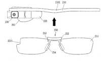
도 2는 본 발명의 일 실시예와 관련된 글래스 타입 단말기(100)의 일 예를 보인 사시도이다.2 is a perspective view showing an example of a
글래스 타입 단말기(100)는 인체의 두부(頭部)에 착용 가능하도록 구성되며, 이를 위한 프레임부(케이스, 하우징 등)을 구비할 수 있다. 프레임부는 착용이 용이하도록 플렉서블 재질로 형성될 수 있다. 본 도면에서는, 프레임부가 서로 다른 재질의 제1 프레임(210a)과 제2 프레임(210b)을 포함하는 것을 예시하고 있다.The
프레임부는 두부에 지지되며, 각종 부품들이 장착되는 공간을 마련한다. 도시된 바와 같이, 프레임부에는 제어 모듈(263), 음향 출력 모듈(261) 등과 같은 전자부품이 장착될 수 있다. 또한, 프레임부에는 좌안 및 우안 중 적어도 하나를 덮는 렌즈(251)가 착탈 가능하게 장착될 수 있다.The frame portion is supported on the head and provides a space in which various parts are mounted. As shown, electronic components such as the
제어 모듈(263)은 글래스 타입 단말기(100)에 구비되는 각종 전자부품을 제어하도록 이루어진다. 제어 모듈(263)은 앞서 설명한 제어부(180)에 대응되는 구성으로 이해될 수 있다. 본 도면에서는, 제어 모듈(263)이 일측 두부 상의 프레임부에 설치된 것을 예시하고 있다. 하지만, 제어 모듈(263)의 위치는 이에 한정되지 않는다.The
디스플레이부(220)는 헤드 마운티드 디스플레이(Head Mounted Display, HMD) 형태로 구현될 수 있다. HMD 형태란, 두부에 장착되어, 사용자의 눈 앞에 직접 영상을 보여주는 디스플레이 방식을 말한다. 사용자가 글래스 타입 단말기(100)를 착용하였을 때, 사용자의 눈 앞에 직접 영상을 제공할 수 있도록, 디스플레이부(220)는 좌안 및 우안 중 적어도 하나에 대응되게 배치될 수 있다. 본 도면에서는, 사용자의 우안을 향하여 영상을 출력할 수 있도록, 디스플레이부(220)가 우안에 대응되는 부분에 위치한 것을 예시하고 있다.The
디스플레이부(220)는 프리즘을 이용하여 사용자의 눈으로 이미지를 투사할 수 있다. 또한, 사용자가 투사된 이미지와 전방의 일반 시야(사용자가 눈을 통하여 바라보는 범위)를 함께 볼 수 있도록, 프리즘은 투광성으로 형성될 수 있다.The
이처럼, 디스플레이부(220)를 통하여 출력되는 영상은, 일반 시야와 오버랩(overlap)되어 보여질 수 있다. 글래스 타입 단말기(200)는 이러한 디스플레이의 특성을 이용하여 현실의 이미지나 배경에 가상 이미지를 겹쳐서 하나의 영상으로 보여주는 증강현실(Augmented Reality, AR)을 제공할 수 있다.In this way, the image output through the
카메라(230)는 좌안 및 우안 중 적어도 하나에 인접하게 배치되어, 전방의 영상을 촬영하도록 형성된다. 카메라(230)가 눈에 인접하여 위치하므로, 카메라(230)는 사용자가 바라보는 장면을 영상으로 획득할 수 있다.The
본 도면에서는, 카메라(230)가 제어 모듈(263)에 구비된 것을 예시하고 있으나, 반드시 이에 한정되는 것은 아니다. 카메라(230)는 상기 프레임부에 설치될 수도 있으며, 복수 개로 구비되어 입체 영상을 획득하도록 이루어질 수도 있다.In this drawing, the
글래스 타입 단말기(200)는 제어명령을 입력 받기 위하여 조작되는 사용자 입력부(262,264)를 구비할 수 있다. 사용자 입력부(262,264)는 터치, 푸시 등 사용자가 촉각적인 느낌을 가면서 조작하게 되는 방식(tactile manner)이라면 어떤 방식이든 채용될 수 있다. 본 도면에서는, 프레임부와 제어 모듈(263)에 각각 푸시 및 터치 입력 방식의 사용자 입력부(262,264)가 구비된 것을 예시하고 있다.The
또한, 글래스 타입 단말기(200)에는 사운드를 입력 받아 전기적인 음성 데이터로 처리하는 마이크로폰(미도시) 및 음향을 출력하는 음향 출력 모듈(261)이 구비될 수 있다. 음향 출력 모듈(261)은 일반적인 음향 출력 방식 또는 골전도 방식으로 음향을 전달하도록 이루어질 수 있다. 음향 출력 모듈(261)이 골전도 방식으로 구현되는 경우, 사용자가 글래스 타입 단말기(200)를 착용시, 음향 출력 모듈(261)은 두부에 밀착되며, 두개골을 진동시켜 음향을 전달하게 된다.In addition, the glass-
이하에서는 이와 같이 구성된 글래스 타입 단말기에서 구현될 수 있는 제어 방법과 관련된 실시 예들에 대해 첨부된 도면을 참조하여 살펴보겠다. 본 발명은 본 발명의 정신 및 필수적 특징을 벗어나지 않는 범위에서 다른 특정한 형태로 구체화될 수 있음은 당업자에게 자명하다.Hereinafter, embodiments related to a control method that can be implemented in a glass type terminal configured as described above will be described with reference to the accompanying drawings. It is obvious to those skilled in the art that the present invention can be embodied in other specific forms without departing from the spirit and essential features of the present invention.
도 3은 본 발명의 일 실시예와 관련된 글래스 타입 단말기(200)의 결합 전의 형상이고, 도 4는 본 발명의 일 실시예와 관련된 글래스 타입 단말기(200)의 결합 후의 형상이다.3 is a shape before the glass-
먼저, 도 3을 참조하면, 프레임(210)에는 카메라(230), 디스플레이부(220) 등이 결합되어 있으며, 안경렌즈(251)를 착용하지 않는 사용자의 경우에는 별도의 안경렌즈(251) 부착장치를 필요로 하지 않으나, 안경을 착용하는 사용자의 경우에는 글래스 타입 단말기(200)에 브릿지(252)를 이용하여 렌즈(251)를 부착하여 사용할 필요가 있다.First, referring to FIG. 3, a
즉, 종래에는 브릿지(252)가 없는 경우가 있을 뿐만 아니라, 브릿지(252)가 있더라도 프레임(210)에 고정되어 있는 경우라면 사용자가 임의로 안경렌즈(251)를 교체할 수가 없는 문제가 있었다.That is, conventionally, there is a problem in that the
본 발명은 이를 해결하기 위한 것으로, 프레임(210)에 체결가능한 브릿지(252)를 구비한다. 도 3은 브릿지(252)에 안경렌즈(251)가 결합된 브릿지(252)를 프레임(210)에 결합하는 과정을 도시한 것이고, 도 4는 상기 결합체(250)가 프레임(210)에 결합된 상태를 도시한 것이다.The present invention is to solve this, and includes a
도 3에 도시된 바와 같이, 사용자는 구입한 렌즈(251)를 스크류(253)를 이용하여 브릿지(252)에 체결할 수 있으며, 좌안 또는 우안 렌즈(251) 중 상기 디스플레이부(220), 카메라(230) 등이 부착되는 부분에는 절곡부(2511)를 형성하여 렌즈(251)가 제어 모듈(263) 등의 배치를 해하지 않으면서 프레임(210)에 결합되도록 한다.As shown in FIG. 3, the user can fasten the purchased
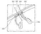
도 5는 본 발명의 일 실시예와 관련된 글래스 타입 단말기(200)의 분해 사시도인데, 도 3 내지 도 5를 참조하면, 본 발명의 일 실시예에 따른 글래스 타입 단말기(200)는 사용자의 두부(頭部)에 거치되는 프레임(210)과, 상기 프레임(210)에 구비되어, 시각 정보를 제공하는 디스플레이부(220)와, 상기 디스플레이부(220)를 제어하는 제어 모듈(263)과, 상기 프레임(210)의 길이 방향을 따라 상기 프레임(210)에 결합되고, 사용자의 코를 받치는 코받침부(254)가 결합되는 브릿지(252)를 포함한다.5 is an exploded perspective view of a glass-
상기 프레임(210)은 외부에 노출되는 외측 프레임(211)과, 상기 외측 프레임(211)의 내측에 결합되고, 사용자의 두부에 접촉하는 내측 프레임(215)을 포함하며, 상기 브릿지(252)는 상기 외측 프레임(211) 및 내측 프레임(215)의 사이에 배치된다. 보다 구체적으로, 상기 브릿지(252)는 외측 프레임(211)과 내측 프레임(215)이 결합될 때 형성되는 공간 내에 배치된다. 이때, 외측은 글래스 타입 단말기(200)를 착용하였을 때, 외부에 노출되는 부분을 의미하고, 내측은 외부에 노출되지 않고, 글래스 타입 단말기(200) 착용시 사용자의 두부가 접촉하는 부분을 의미한다.The
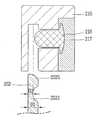
또한, 도 9에 도시된 바와 같이, 상기 외측 프레임(211)은 상면을 형성하고, 내측으로 향하는 제1 부분(211a)과, 상기 제1 부분(211a)으로부터 하부로 연장되는 제2 부분(211b), 및 상기 제2 부분(211b)으로부터 내측으로 연장되는 제3 부분(211c)을 포함하여 이루어진다. 즉, 상기 외측 프레임(211)은 대략 'ㄷ' 또는 'C' 형상을 갖는다.In addition, as shown in FIG. 9, the
본 발명의 일 실시예에서는 상면은 글래스 타입 단말기(200)를 착용하였을 때, 노출되는 면이 윗 방향을 향하는 부분을 의미하고, 전면은 노출되는 면이 정면을 향하는 경우를 의미하고, 하면은 노출되는 면이 아랫 방향을 향하는 것을 의미한다.In one embodiment of the present invention, the upper surface refers to a portion in which the exposed surface faces upward when the
예를 들어, 도 9를 참조하면, 상기 제1 부분(211a)의 노출되는 면이 윗 방향을 향하고 있으므로, 상면을 형성하고, 제2 부분(211b)의 노출되는 면이 정면을 향하므로 전면을 형성하며, 제3 부분(211c)의 노출되는 면은 아랫 방향을 향하여 형성되어 하면을 형성한다.For example, referring to FIG. 9, since the exposed surface of the
상기 브릿지(252)는 상기 프레임(210)에 삽입되어 외부에 노출되지 않는 삽입부(2523)와, 상기 삽입부(2523)로부터 하부로 연장되어 외부에 노출되며, 상기 코받침부(254)가 결합되는 노출부(2522))를 포함하는데, 상기 삽입부(2523)는 상기 프레임(210)의 길이 방향(횡 방향)을 따라 형성되고, 상기 노출부(2522)는 상기 삽입부(2523)와 대략 수직으로 형성되며, 코받침부(254)가 결합되어야 하므로 쌍으로 형성된다. 이때, 한 쌍의 코받침부(254)는 서로 평행으로 형성될 수도 있으나, 코의 형상을 반영하여 콧등과의 안정적인 접촉을 위하여 아래로 갈수록 서로 멀어지는 방향으로 형성되는 것이 바람직하다. 즉, 상기 노출부(2522)는 상기 삽입부(2523)의 하단으로부터 양측 아래로 형성된다.The
상기 브릿지(252)는 프레임(210)이 완전히 조립된 상태에서 외부에서부터 삽입되고, 고정되어야 하므로, 상기 브릿지(252)가 삽입되는 통로가 필요하다. 이를 위하여 본 발명에 따른 일 실시예에서는 상기 제3 부분(211c)에 브릿지(252) 삽입구(2113)를 프레임(210)의 길이 방향을 따라 형성하였다.Since the
도 5를 참조하면, 상기 삽입구(2113)의 아래로부터 프레임(210)의 내부로 브릿지(252)가 삽입되도록 외측 프레임(211)의 제3 부분(211c)에 삽입구(2113)가 형성된다. 상기 브릿지(252)는 외측 프레임(211)의 하부로부터 삽입되지만, 외측 프레임(211)에 의해 고정되는 것은 아니다. 본 발명의 일 실시예에서는 상기 브릿지(252)는 내측 프레임(215)에 삽입되도록 하고 있다. 도 9에 도시된 바와 같이, 상기 내측 프레임(215)의 외측면에는 상기 브릿지(252)가 삽입될 수 있는 공간이 형성된 굽힘부재(2154)가 배치된다. 상기 굽힘부재(2154)는 대략 'L'형상이며, 내측 프레임(215)과 함께 형성되는 공간에는 브릿지(252)가 삽입된다.Referring to FIG. 5, an
한편, 상기 제1 내지 제3 부분(211a,211b,211c)에 의해 형성되는 공간 중 상기 제2 부분(211b)의 내측면에는 연성 회로기판(213)이 배치되는데, 상기 굽힘부재(2154)에 의해 상기 연성 회로기판(213)과 브릿지(252)가 공간적으로 이격되도록 한다. 상기 굽힘부재(2154)는 상기 내측 프레임(215)으로부터 상기 외측 프레임(211)을 향하여 연장되는 연장부(2154a)와, 상기 연장부(2154a)로부터 수직으로 형성되어 상기 연성 회로기판(213)이 접촉되는 부분인 수직부(2154b)를 포함하여 이루어진다. 상기 연장부(2154a)와 수직부(2154b)는 서로 수직을 이루므로, "L"형상을 이룬다.Meanwhile, a
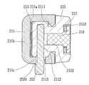
또한, 본 발명의 일 실시예에 따르면, 상기 굽힘부재(2154)의 내부 공간으로 삽입되는 브릿지(252)가 아래 방향으로 이탈되지 않도록 하기 위하여 하나 이상의 핀(216)이 사용된다. 상기 핀(216)은 상기 내측 프레임(215)의 내측면에 형성되는 그루브(2153,groove)에 형성된다. 상기 그루브(2153)는 상기 삽입구(2113)와 대응되는 길이를 가지며, 상기 내측 프레임(215)의 수직면 상에 형성되며, 상기 플레이트(217)에는 상기 핀(216)이 관통하는 제1 홀(2151)이 형성된다. 상기 핀(216)의 선단부(2161)는 상기 제1 홀(2151)을 관통하여 상기 브릿지(252)와 접촉하게 되는데, 상기 브릿지(252)가 이탈되지 않도록 고정하기 위하여 상기 브릿지(252)에는 상기 핀(216)이 수용되는 수용홈(2521)이 형성된다. 상기 수용홈(2521)은 상기 핀(216)의 선단부(2161)의 형상과 요철(凹凸) 결합이 가능하도록 형성된다.In addition, according to an embodiment of the present invention, one or
또한, 상기 그루브(2153)에는 상기 핀(216)을 가압하여 상기 핀(216)이 내측으로 돌출되는 것을 방지하는 플레이트(217)가 배치되고, 상기 플레이트(217)에는 제2 홀(2152)이 형성되어 스크류(218)에 의해 상기 플레이트(217)를 상기 내측 프레임(215)에 밀착시키도록 한다. 이때, 상기 플레이트(217)는 평판형의 플레이트(217)로 탄성이 있는 것을 사용한다.In addition, a
즉, 상기 그루브(2153)에는 플레이트(217)가 배치되며, 상기 플레이트(217)에는 하나 이상의 제2 홀(2152)이 형성되며, 상기 핀(216)은 상기 내측 프레임(215)을 관통하여 상기 브릿지(252)에 접촉하게 되고, 스크류(218)는 상기 플레이트(217)를 상기 내측 프레임(215)에 밀착시킴과 동시에 상기 핀(216)이 외부로 튀어나오지 못하도록 하는 역할을 한다.That is, a
도 7은 프레임(210), 보다 구체적으로는 내측 프레임(215)에 상기 핀(216)이 상기 탄력을 갖는 플레이트(217)를 관통하여 결합되고, 상기 플레이트(217)는 스크류(218)에 의해 상기 내측 프레임(215)에 체결된 상태에서 브릿지(252)가 굽힘부재(2154) 내로 삽입되는 과정을 도시한 것이다.7 is a
상기 브릿지(252)의 수용홈(2521) 이외의 부분에서의 두께는 D1인 반면, 상기 수용홈(2521) 부분에서의 두께는 D2로, 수용홈(2521)에서의 두께가 더 얇다. 이와 같은 구조에 의하여 상기 브릿지(252)의 상단부(2525)가 굽힘부재(2154) 내로 삽입되어 상기 핀(216)의 선단부(2161)와 접촉하게 되면 브릿지(252)는 더 이상 이동하지 않게 된다.The thickness of the
따라서, 상기 브릿지(252)를 상기 굽힘부재(2154)의 내부로 삽입하기 위해서는 상기 브릿지(252)를 강제로 밀어올려야 한다. 이와 같이 강제로 브릿지(252)가 삽입되는 동안 도 8a에 도시된 바와 같이, 플레이트(217)는 스크류(218)를 중심으로 활처럼 휘게 된다. 이와 같은 상태에서 계속하여 브릿지(252)를 삽입시키면 상기 핀(216)의 선단부(2161)가 상기 수용홈(2521)에 안착되게 된다. 상기 핀(216)이 수용홈(2521)에 안착되면, 도 8b에 도시된 바와 같이, 플레이트(217)는 상기 내측 프레임(215)의 그루브(2153)에 접촉되거나 거의 접촉될 수 있는 상태가 된다.Therefore, in order to insert the
이때, 상기 그루브(2153)의 높이는 상기 플레이트(217)의 두께보다 더 크도록 하는 것이 바람직하다. 보다 구체적으로, 상기 플레이트(217)와 내측 프레임(215)의 최대 이격 거리(H')는 상기 그루브(2153)의 높이보다 작아야 한다. 또한, 상기 스크류(218)의 최대 노출 높이 또한 상기 그루브(2153)의 높이보다는 작아야 한다. 왜냐 하면, 상기 내측 프레임(215)의 내측면은 사용자의 두부에 직접 접촉하는 부분이므로, 내측으로 돌출되는 부분이 없어야 하기 때문이다. 다만, 도 8a에 도시된 바와 같이, 브릿지(252)를 삽입하는 과정에서 플레이트(217)의 끝단부가 내측 프레임(215)으로부터 이격되는 높이(H)는 과도하게 높지만 않으면 된다. 이와 같이 함으로써 상기 플레이트(217)가 상기 그루브(2153)에 수용될 수 있도록 하며, 상기 플레이트(217)는 상기 그루브(2153)의 형성 방향을 따라 형성된다.In this case, it is preferable that the height of the
한편, 상기 굽힘부재(2154)는 상기 외측 프레임(211)의 내측면에 수용되는데, 이를 위하여 상기 외측 프레임(211)에는 도 5에 도시된 바와 같이, 리세스부(2114a,2114b,recess portion)가 형성된다. 보다 구체적으로는 상기 제1 부분(211a)의 일 부분에 형성된다. 상기 리세스부(2114a,2114b) 사이에는 돌출부(2111)가 형성된다.On the other hand, the bending
즉, 도 9를 참조하면, 상기 제1 부분(211a) 및 제3 부분(211c)의 끝단은 서로 마주하도록 돌출되는 돌출부(2111,2112)가 형성되고, 상기 내측 프레임(215)에는 상기 돌출부(2111,2112)가 삽입되어 상기 외측 프레임(211)과 내측 프레임(215)이 결합되도록 할 수 있다.That is, referring to FIG. 9,
또한, 도 3에 도시된 바와 같이, 상기 브릿지(252)의 하단은 상기 삽입구(2113)에 걸림되도록 돌출되는 단차부(2524)가 형성되며, 상기 프레임(210)은 상기 브릿지(252)와 결합하는 부분(2101)이 다른 부분보다 아래 방향으로 휘어지거나, 브릿지(252)와 결합하는 부분(2101)이 내측을 향하여 휘어지도록 한다.In addition, as shown in Figure 3, the lower end of the
이와 같이 함으로써, 글래스 타입 단말기(200)가 사용자의 코 부분에 안착되기 쉽게 된다.
In this way, the
상기의 상세한 설명은 모든 면에서 제한적으로 해석되어서는 아니되고 예시적인 것으로 고려되어야 한다. 본 발명의 범위는 첨부된 청구항의 합리적 해석에 의해 결정되어야 하고, 본 발명의 등가적 범위 내에서의 모든 변경은 본 발명의 범위에 포함된다.
The above detailed description should not be construed as restrictive in all respects and should be considered as illustrative. The scope of the present invention should be determined by rational interpretation of the appended claims, and all changes within the equivalent scope of the present invention are included in the scope of the present invention.
Claims (17)
Translated fromKorean상기 프레임에 구비되어, 시각 정보를 제공하는 디스플레이부;
상기 디스플레이를 제어하는 제어 모듈; 및
상기 프레임의 길이 방향을 따라 상기 프레임에 결합되고, 사용자의 코를 받치는 코받침부가 결합되는 브릿지를 포함하고,
상기 프레임은,
외부에 노출되는 외측 프레임과, 상기 외측 프레임의 내측에 결합되고, 사용자의 두부에 접촉하는 내측 프레임을 포함하고,
상기 브릿지는 상기 외측 프레임 및 내측 프레임의 사이에 배치되며, 상기 내측 프레임의 내측면에는 그루브(groove)가 형성되고, 상기 그루브에는 핀이 삽입되는 제1 홀이 형성하며,
상기 그루브에는 상기 핀을 가압하도록 형성되는 플레이트가 배치되고, 상기 플레이트에는 제2 홀이 형성되어 스크류에 의해 상기 플레이트를 상기 내측 프레임에 밀착시키고,
상기 브릿지에는 리세스되도록 상기 핀을 수용하는 수용홈이 형성되며, 상기 플레이트는 상기 핀을 상기 수용홈을 향해 가압하는 것을 특징으로 하는 글래스 타입 단말기.A frame mounted on the user's head;
A display unit provided in the frame and providing visual information;
A control module for controlling the display; And
It is coupled to the frame along the longitudinal direction of the frame, and includes a bridge to which a nose support portion for supporting the user's nose is coupled,
The frame,
An outer frame exposed to the outside and an inner frame coupled to the inner side of the outer frame and in contact with the user's head,
The bridge is disposed between the outer frame and the inner frame, a groove is formed in the inner surface of the inner frame, and a first hole into which a pin is inserted is formed in the groove,
A plate formed to press the pin is disposed in the groove, and a second hole is formed in the plate so that the plate is in close contact with the inner frame by a screw,
The bridge is formed with a receiving groove for receiving the pin to be recessed, the glass type terminal, characterized in that the plate presses the pin toward the receiving groove.
상기 외측 프레임은,
상면을 형성하고, 내측으로 향하는 제1 부분;
상기 제1 부분으로부터 하부로 연장되는 제2 부분; 및
상기 제2 부분으로부터 내측으로 연장되는 제3 부분을 포함하는 것을 특징으로 하는 글래스 타입 단말기.The method of claim 1,
The outer frame,
A first portion forming an upper surface and facing inward;
A second portion extending downward from the first portion; And
And a third portion extending inward from the second portion.
상기 브릿지는,
상기 프레임에 삽입되는 삽입부와, 상기 삽입부로부터 하부로 연장되어 외부에 노출되며, 상기 코받침부가 결합되는 노출부를 포함하며,
상기 제3 부분에는 상기 브릿지가 삽입되는 삽입구가 길이 방향을 따라 형성되는 것을 특징으로 하는 글래스 타입 단말기.The method of claim 2,
The bridge,
An insertion part inserted into the frame, and an exposure part extending downward from the insertion part to be exposed to the outside, and to which the nose support part is coupled,
The glass type terminal, characterized in that the third part has an insertion hole into which the bridge is inserted along a length direction.
상기 브릿지에는 상기 핀이 수용되는 수용홈이 형성되며, 상기 수용홈은 상기 핀의 선단부와 요철 결합되는 것을 특징으로 하는 글래스 타입 단말기.The method of claim 3,
The bridge is provided with a receiving groove for receiving the pin, the receiving groove is a glass type terminal, characterized in that the concave-convex coupling with the tip of the pin.
상기 제1 내지 제3 부분에 의해 형성되는 공간에는 연성 회로기판이 배치되며,
상기 내측 프레임은,
상기 브릿지가 삽입되고, 상기 연성 회로기판과 브릿지를 이격시키는 굽힘부재가 형성되며,
상기 제1 부분에는 상기 굽힘부재가 수용되는 리세스부(recess portion)가 형성되는 것을 특징으로 하는 글래스 타입 단말기.
The method of claim 2,
A flexible circuit board is disposed in the space formed by the first to third parts,
The inner frame,
The bridge is inserted, and a bending member is formed to separate the flexible circuit board and the bridge,
A glass type terminal, characterized in that a recess portion in which the bending member is accommodated is formed in the first portion.
Priority Applications (4)
| Application Number | Priority Date | Filing Date | Title |
|---|---|---|---|
| KR1020140081171AKR102212031B1 (en) | 2014-06-30 | 2014-06-30 | Glass type terminal |
| US14/742,499US9612453B2 (en) | 2014-06-30 | 2015-06-17 | Glasses-type terminal |
| EP15172841.7AEP2963479B1 (en) | 2014-06-30 | 2015-06-19 | Glasses-type head mounted display |
| CN201510369008.XACN105227703B (en) | 2014-06-30 | 2015-06-29 | Glasses type terminal |
Applications Claiming Priority (1)
| Application Number | Priority Date | Filing Date | Title |
|---|---|---|---|
| KR1020140081171AKR102212031B1 (en) | 2014-06-30 | 2014-06-30 | Glass type terminal |
Publications (2)
| Publication Number | Publication Date |
|---|---|
| KR20160002190A KR20160002190A (en) | 2016-01-07 |
| KR102212031B1true KR102212031B1 (en) | 2021-02-04 |
Family
ID=53483708
Family Applications (1)
| Application Number | Title | Priority Date | Filing Date |
|---|---|---|---|
| KR1020140081171AActiveKR102212031B1 (en) | 2014-06-30 | 2014-06-30 | Glass type terminal |
Country Status (4)
| Country | Link |
|---|---|
| US (1) | US9612453B2 (en) |
| EP (1) | EP2963479B1 (en) |
| KR (1) | KR102212031B1 (en) |
| CN (1) | CN105227703B (en) |
Families Citing this family (12)
| Publication number | Priority date | Publication date | Assignee | Title |
|---|---|---|---|---|
| US10754175B2 (en) | 2016-02-18 | 2020-08-25 | Lg Electronics Inc. | Head-mounted display |
| WO2017171157A1 (en)* | 2016-03-30 | 2017-10-05 | 엘지전자 주식회사 | Wearable device |
| US10466491B2 (en) | 2016-06-01 | 2019-11-05 | Mentor Acquisition One, Llc | Modular systems for head-worn computers |
| US11156855B2 (en)* | 2016-05-09 | 2021-10-26 | Oakley, Inc. | Modular wearable electronic devices, systems, and methods |
| CN108089326B (en)* | 2018-02-01 | 2023-12-26 | 北京七鑫易维信息技术有限公司 | Device suitable for being used with glasses |
| US11509883B2 (en)* | 2019-03-19 | 2022-11-22 | Lg Electronics Inc. | Electronic device |
| US12245367B2 (en) | 2019-08-05 | 2025-03-04 | Lg Electronics Inc. | Head wearable electronic device and method for manufacturing the same |
| KR102808965B1 (en)* | 2019-08-09 | 2025-05-20 | 엘지전자 주식회사 | Electronic device |
| US12007810B2 (en)* | 2020-04-23 | 2024-06-11 | Apple Inc. | Electronic devices with antennas and optical components |
| KR20220017272A (en)* | 2020-08-04 | 2022-02-11 | 삼성전자주식회사 | Wearable electronic device |
| ES1305085U (en)* | 2023-08-04 | 2024-01-19 | Soler Francisco Rausell | Vision device for users (Machine-translation by Google Translate, not legally binding) |
| ES2995434A1 (en)* | 2023-08-04 | 2025-02-10 | Soler Francisco Rausell | Vision device for users |
Citations (2)
| Publication number | Priority date | Publication date | Assignee | Title |
|---|---|---|---|---|
| KR101033606B1 (en) | 2010-10-04 | 2011-05-11 | 알랭 미끌리 인터네셔널 | glasses |
| WO2014097782A1 (en)* | 2012-12-18 | 2014-06-26 | OHURA Issei | Fixing structure for eyeglass lens assembly, and eyeglasses |
Family Cites Families (11)
| Publication number | Priority date | Publication date | Assignee | Title |
|---|---|---|---|---|
| US20120105740A1 (en) | 2000-06-02 | 2012-05-03 | Oakley, Inc. | Eyewear with detachable adjustable electronics module |
| CN1720763B (en)* | 2002-07-26 | 2013-06-12 | 奥克利有限公司 | Glasses |
| FR2915003B1 (en) | 2007-04-10 | 2009-12-25 | Logo Sa | GLASSES WITH INTERCHANGEABLE FRAME |
| CN201557262U (en)* | 2009-12-03 | 2010-08-18 | 北京市信息技术应用研究所 | an information receiving device |
| WO2011106797A1 (en)* | 2010-02-28 | 2011-09-01 | Osterhout Group, Inc. | Projection triggering through an external marker in an augmented reality eyepiece |
| KR101241918B1 (en)* | 2011-02-24 | 2013-03-11 | 엘지전자 주식회사 | Glasses |
| US9285592B2 (en)* | 2011-08-18 | 2016-03-15 | Google Inc. | Wearable device with input and output structures |
| US8971023B2 (en)* | 2012-03-21 | 2015-03-03 | Google Inc. | Wearable computing device frame |
| US9075249B2 (en)* | 2012-03-07 | 2015-07-07 | Google Inc. | Eyeglass frame with input and output functionality |
| US20130258271A1 (en) | 2012-03-28 | 2013-10-03 | Google Inc. | Sliding Frame |
| JP5462931B1 (en) | 2012-12-29 | 2014-04-02 | 一成 大浦 | Fixing structure of spectacle lens assembly and spectacles |
- 2014
- 2014-06-30KRKR1020140081171Apatent/KR102212031B1/enactiveActive
- 2015
- 2015-06-17USUS14/742,499patent/US9612453B2/enactiveActive
- 2015-06-19EPEP15172841.7Apatent/EP2963479B1/enactiveActive
- 2015-06-29CNCN201510369008.XApatent/CN105227703B/enactiveActive
Patent Citations (2)
| Publication number | Priority date | Publication date | Assignee | Title |
|---|---|---|---|---|
| KR101033606B1 (en) | 2010-10-04 | 2011-05-11 | 알랭 미끌리 인터네셔널 | glasses |
| WO2014097782A1 (en)* | 2012-12-18 | 2014-06-26 | OHURA Issei | Fixing structure for eyeglass lens assembly, and eyeglasses |
Also Published As
| Publication number | Publication date |
|---|---|
| US9612453B2 (en) | 2017-04-04 |
| KR20160002190A (en) | 2016-01-07 |
| CN105227703B (en) | 2019-10-15 |
| EP2963479A1 (en) | 2016-01-06 |
| US20150378171A1 (en) | 2015-12-31 |
| CN105227703A (en) | 2016-01-06 |
| EP2963479B1 (en) | 2019-02-27 |
Similar Documents
| Publication | Publication Date | Title |
|---|---|---|
| KR102212031B1 (en) | Glass type terminal | |
| KR102176364B1 (en) | Glass type terminal | |
| KR102091520B1 (en) | Mobile terminal | |
| KR101726676B1 (en) | Head mounted display | |
| KR102221468B1 (en) | Glass type terminal | |
| KR102063105B1 (en) | Mobile terminal | |
| EP3220196A1 (en) | Wearable device | |
| JP2016122177A (en) | Display device and control method of display device | |
| US20230034288A1 (en) | Wearable electronic device including display | |
| KR20200032467A (en) | Electronic device having optical member for adjusting permeation rate of light and method for operating thereof | |
| EP4621538A1 (en) | Wearable device and method for displaying multimedia content provided by external electronic device | |
| KR20150084603A (en) | Near to eye display and wearable device having the same | |
| EP4465644A1 (en) | Camera module and electronic device comprising same | |
| EP4610798A1 (en) | Wearable device for displaying media content on basis of grip form with respect to external object, and method for same | |
| KR20250028944A (en) | Wearable device, method, and non-transitory computer readable storage medium for adjusting brightness of environment | |
| KR20240097658A (en) | Wearable device for displaying multimedia content provided by external electronic device and method thereof | |
| KR20240097656A (en) | Wearable device for switching screen based on biometric data obtained from external electronic device and method thereof | |
| KR20250146117A (en) | Wearable device, method, and computer-readable storage medium for touch input in three dimensional space | |
| KR20240132828A (en) | Electronic device for controlling virtual object based on distance between virtual objects and method thereof | |
| KR20240028262A (en) | Wearable electronic device for controlling camera module and method for operating thereof | |
| CN120513464A (en) | Electronic device and method for controlling virtual objects based on distance between virtual objects | |
| KR20180041485A (en) | Case of mobile terminal | |
| KR20160086704A (en) | Electronic device |
Legal Events
| Date | Code | Title | Description |
|---|---|---|---|
| PA0109 | Patent application | Patent event code:PA01091R01D Comment text:Patent Application Patent event date:20140630 | |
| PG1501 | Laying open of application | ||
| PA0201 | Request for examination | Patent event code:PA02012R01D Patent event date:20190530 Comment text:Request for Examination of Application Patent event code:PA02011R01I Patent event date:20140630 Comment text:Patent Application | |
| E902 | Notification of reason for refusal | ||
| PE0902 | Notice of grounds for rejection | Comment text:Notification of reason for refusal Patent event date:20200710 Patent event code:PE09021S01D | |
| E701 | Decision to grant or registration of patent right | ||
| PE0701 | Decision of registration | Patent event code:PE07011S01D Comment text:Decision to Grant Registration Patent event date:20210125 | |
| PR0701 | Registration of establishment | Comment text:Registration of Establishment Patent event date:20210129 Patent event code:PR07011E01D | |
| PR1002 | Payment of registration fee | Payment date:20210201 End annual number:3 Start annual number:1 | |
| PG1601 | Publication of registration |