KR102210306B1 - Test Apparatus for Analysing Body Fluid - Google Patents
Test Apparatus for Analysing Body FluidDownload PDFInfo
- Publication number
- KR102210306B1 KR102210306B1KR1020180101355AKR20180101355AKR102210306B1KR 102210306 B1KR102210306 B1KR 102210306B1KR 1020180101355 AKR1020180101355 AKR 1020180101355AKR 20180101355 AKR20180101355 AKR 20180101355AKR 102210306 B1KR102210306 B1KR 102210306B1
- Authority
- KR
- South Korea
- Prior art keywords
- assembly
- body fluid
- fluid
- target
- observation sheet
- Prior art date
- Legal status (The legal status is an assumption and is not a legal conclusion. Google has not performed a legal analysis and makes no representation as to the accuracy of the status listed.)
- Active
Links
- 210000001124body fluidAnatomy0.000titleclaimsabstractdescription120
- 239000010839body fluidSubstances0.000titleclaimsabstractdescription79
- 238000012360testing methodMethods0.000titleclaimsabstractdescription43
- 230000008878couplingEffects0.000claimsdescription28
- 238000010168coupling processMethods0.000claimsdescription28
- 238000005859coupling reactionMethods0.000claimsdescription28
- 238000004891communicationMethods0.000claimsdescription15
- 230000035515penetrationEffects0.000claimsdescription11
- 230000001939inductive effectEffects0.000claimsdescription3
- 230000000149penetrating effectEffects0.000claimsdescription3
- 238000002347injectionMethods0.000claimsdescription2
- 239000007924injectionSubstances0.000claimsdescription2
- 239000000463materialSubstances0.000description9
- 230000006698inductionEffects0.000description6
- 230000035935pregnancyEffects0.000description5
- 230000000694effectsEffects0.000description4
- 230000036512infertilityEffects0.000description4
- 208000000509infertilityDiseases0.000description4
- 231100000535infertilityToxicity0.000description4
- 238000000034methodMethods0.000description4
- 229920003002synthetic resinPolymers0.000description4
- 239000000057synthetic resinSubstances0.000description4
- 238000011109contaminationMethods0.000description3
- 238000003745diagnosisMethods0.000description3
- 230000008901benefitEffects0.000description2
- 230000005540biological transmissionEffects0.000description2
- 239000008280bloodSubstances0.000description2
- 210000004369bloodAnatomy0.000description2
- 238000005516engineering processMethods0.000description2
- 238000007689inspectionMethods0.000description2
- 239000002184metalSubstances0.000description2
- 239000003973paintSubstances0.000description2
- 230000008569processEffects0.000description2
- 210000003296salivaAnatomy0.000description2
- 239000004698PolyethyleneSubstances0.000description1
- NIXOWILDQLNWCW-UHFFFAOYSA-Nacrylic acid groupChemical groupC(C=C)(=O)ONIXOWILDQLNWCW-UHFFFAOYSA-N0.000description1
- 239000000853adhesiveSubstances0.000description1
- 230000001070adhesive effectEffects0.000description1
- 230000000295complement effectEffects0.000description1
- 206010012601diabetes mellitusDiseases0.000description1
- 230000035558fertilityEffects0.000description1
- 239000011521glassSubstances0.000description1
- 230000036541healthEffects0.000description1
- 229940088597hormoneDrugs0.000description1
- 239000005556hormoneSubstances0.000description1
- 239000007788liquidSubstances0.000description1
- 238000012986modificationMethods0.000description1
- 230000004048modificationEffects0.000description1
- 230000001151other effectEffects0.000description1
- 230000016087ovulationEffects0.000description1
- 239000012466permeateSubstances0.000description1
- 229920000515polycarbonatePolymers0.000description1
- 239000004417polycarbonateSubstances0.000description1
- -1polyethylenePolymers0.000description1
- 229920000573polyethylenePolymers0.000description1
- 238000009597pregnancy testMethods0.000description1
- 230000004044responseEffects0.000description1
- 230000028327secretionEffects0.000description1
- 210000000582semenAnatomy0.000description1
- 230000035939shockEffects0.000description1
- 239000000126substanceSubstances0.000description1
- 210000004243sweatAnatomy0.000description1
- 239000012780transparent materialSubstances0.000description1
- 230000032258transportEffects0.000description1
- 210000002700urineAnatomy0.000description1
Images


Classifications
- A—HUMAN NECESSITIES
- A61—MEDICAL OR VETERINARY SCIENCE; HYGIENE
- A61B—DIAGNOSIS; SURGERY; IDENTIFICATION
- A61B5/00—Measuring for diagnostic purposes; Identification of persons
- A61B5/145—Measuring characteristics of blood in vivo, e.g. gas concentration or pH-value ; Measuring characteristics of body fluids or tissues, e.g. interstitial fluid or cerebral tissue
- A61B5/14507—Measuring characteristics of blood in vivo, e.g. gas concentration or pH-value ; Measuring characteristics of body fluids or tissues, e.g. interstitial fluid or cerebral tissue specially adapted for measuring characteristics of body fluids other than blood
- A—HUMAN NECESSITIES
- A61—MEDICAL OR VETERINARY SCIENCE; HYGIENE
- A61B—DIAGNOSIS; SURGERY; IDENTIFICATION
- A61B5/00—Measuring for diagnostic purposes; Identification of persons
- A61B5/0059—Measuring for diagnostic purposes; Identification of persons using light, e.g. diagnosis by transillumination, diascopy, fluorescence
- A—HUMAN NECESSITIES
- A61—MEDICAL OR VETERINARY SCIENCE; HYGIENE
- A61B—DIAGNOSIS; SURGERY; IDENTIFICATION
- A61B10/00—Instruments for taking body samples for diagnostic purposes; Other methods or instruments for diagnosis, e.g. for vaccination diagnosis, sex determination or ovulation-period determination; Throat striking implements
- A61B10/0045—Devices for taking samples of body liquids
- A61B10/0051—Devices for taking samples of body liquids for taking saliva or sputum samples
- A—HUMAN NECESSITIES
- A61—MEDICAL OR VETERINARY SCIENCE; HYGIENE
- A61B—DIAGNOSIS; SURGERY; IDENTIFICATION
- A61B5/00—Measuring for diagnostic purposes; Identification of persons
- A61B5/145—Measuring characteristics of blood in vivo, e.g. gas concentration or pH-value ; Measuring characteristics of body fluids or tissues, e.g. interstitial fluid or cerebral tissue
- A61B5/1455—Measuring characteristics of blood in vivo, e.g. gas concentration or pH-value ; Measuring characteristics of body fluids or tissues, e.g. interstitial fluid or cerebral tissue using optical sensors, e.g. spectral photometrical oximeters
- A—HUMAN NECESSITIES
- A61—MEDICAL OR VETERINARY SCIENCE; HYGIENE
- A61B—DIAGNOSIS; SURGERY; IDENTIFICATION
- A61B5/00—Measuring for diagnostic purposes; Identification of persons
- A61B5/43—Detecting, measuring or recording for evaluating the reproductive systems
- A61B5/4375—Detecting, measuring or recording for evaluating the reproductive systems for evaluating the male reproductive system
- A—HUMAN NECESSITIES
- A61—MEDICAL OR VETERINARY SCIENCE; HYGIENE
- A61B—DIAGNOSIS; SURGERY; IDENTIFICATION
- A61B5/00—Measuring for diagnostic purposes; Identification of persons
- A61B5/68—Arrangements of detecting, measuring or recording means, e.g. sensors, in relation to patient
- A61B5/6887—Arrangements of detecting, measuring or recording means, e.g. sensors, in relation to patient mounted on external non-worn devices, e.g. non-medical devices
- A61B5/6898—Portable consumer electronic devices, e.g. music players, telephones, tablet computers
- G—PHYSICS
- G01—MEASURING; TESTING
- G01N—INVESTIGATING OR ANALYSING MATERIALS BY DETERMINING THEIR CHEMICAL OR PHYSICAL PROPERTIES
- G01N21/00—Investigating or analysing materials by the use of optical means, i.e. using sub-millimetre waves, infrared, visible or ultraviolet light
- G01N21/17—Systems in which incident light is modified in accordance with the properties of the material investigated
- G—PHYSICS
- G01—MEASURING; TESTING
- G01N—INVESTIGATING OR ANALYSING MATERIALS BY DETERMINING THEIR CHEMICAL OR PHYSICAL PROPERTIES
- G01N33/00—Investigating or analysing materials by specific methods not covered by groups G01N1/00 - G01N31/00
- G01N33/48—Biological material, e.g. blood, urine; Haemocytometers
- G01N33/483—Physical analysis of biological material
- G01N33/487—Physical analysis of biological material of liquid biological material
- H—ELECTRICITY
- H04—ELECTRIC COMMUNICATION TECHNIQUE
- H04M—TELEPHONIC COMMUNICATION
- H04M1/00—Substation equipment, e.g. for use by subscribers
- H04M1/02—Constructional features of telephone sets
- H04M1/21—Combinations with auxiliary equipment, e.g. with clocks or memoranda pads
- G—PHYSICS
- G01—MEASURING; TESTING
- G01N—INVESTIGATING OR ANALYSING MATERIALS BY DETERMINING THEIR CHEMICAL OR PHYSICAL PROPERTIES
- G01N2201/00—Features of devices classified in G01N21/00
- G01N2201/06—Illumination; Optics
- G01N2201/063—Illuminating optical parts
Landscapes
- Health & Medical Sciences (AREA)
- Life Sciences & Earth Sciences (AREA)
- Engineering & Computer Science (AREA)
- Biomedical Technology (AREA)
- Physics & Mathematics (AREA)
- Pathology (AREA)
- General Health & Medical Sciences (AREA)
- Molecular Biology (AREA)
- Heart & Thoracic Surgery (AREA)
- Medical Informatics (AREA)
- Surgery (AREA)
- Animal Behavior & Ethology (AREA)
- Public Health (AREA)
- Veterinary Medicine (AREA)
- Biophysics (AREA)
- Chemical & Material Sciences (AREA)
- Hematology (AREA)
- Analytical Chemistry (AREA)
- Biochemistry (AREA)
- General Physics & Mathematics (AREA)
- Immunology (AREA)
- Medicinal Chemistry (AREA)
- Urology & Nephrology (AREA)
- Food Science & Technology (AREA)
- Optics & Photonics (AREA)
- Pulmonology (AREA)
- Signal Processing (AREA)
- Multimedia (AREA)
- Gynecology & Obstetrics (AREA)
- Reproductive Health (AREA)
- Spectroscopy & Molecular Physics (AREA)
- Investigating Or Analysing Biological Materials (AREA)
- Sampling And Sample Adjustment (AREA)
Abstract
Translated fromKoreanDescription
Translated fromKorean본 발명은 체액 분석용 검사 장치에 관한 것으로, 보다 상세하게는 장소나 시간의 제약 없이 사용자가 직접 체액을 검사하고 체액의 분석 결과를 사용자 단말을 통해 확인할 수 있도록 한 체액 분석용 검사 장치에 관한 것이다.The present invention relates to a body fluid analysis test device, and more particularly, to a body fluid analysis test device in which a user can directly test a body fluid without restriction of a place or time and check the analysis result of the body fluid through a user terminal. .
일반적으로, 사람들은 자신의 건강이나 신체 상태를 확인하기 위하여 전문 의료기관을 방문해야 하지만, 전문 의료기관을 방문하여 검진을 받기 위해서는 바쁜 일과시간을 쪼개야 하고, 복잡한 과정의 수속을 진행해야 하므로 많은 시간과 비용이 소요된다. 이로 인해, 대부분의 사람들은 어지간한 불편함은 감수하며 생활하고, 견디기 힘든 정도의 고통 또는 불편함이 발생해야만 전문 의료기관을 이용하는 실정이다. 이러한 불편함을 해소하기 위하여 각종 첨단장비를 이용하여 신체 상태를 빈번하게 확인하고, 이를 네트워크를 통해 전문 의료기관에 전달하여 체크하는 기술들이 개발되었지만, 실제로 상용화되어 이용되는 기술은 극히 드문 실정이다.In general, people have to visit a specialized medical institution to check their health or physical condition. However, in order to visit a specialized medical institution and receive a checkup, it is necessary to break down busy work hours and proceed with complicated procedures. It costs money. For this reason, most people live with considerable discomfort, and use specialized medical institutions only when pain or discomfort occurs to a degree that is difficult to bear. In order to alleviate such inconvenience, technologies have been developed to frequently check the physical condition using various high-tech equipment and transmit it to specialized medical institutions through a network to check, but the technology that is actually commercialized and used is extremely rare.
오히려, 과거로부터 사용되어온 간단한 테스트기의 사용은 꾸준히 증가하고 있으며, 특히, 편리한 사용 방법, 적은 비용, 전문 의료기관의 이용 시 불편함을 해소할 수 있기 때문에 젊은 세대들 사이에서 사용률이 더욱 증가하고 있다.Rather, the use of simple testing machines that have been used from the past is steadily increasing, and in particular, the usage rate among the younger generation is increasing further because it can relieve the inconvenience when using a convenient method, low cost, and use of a specialized medical institution.
이와 같은 테스트기는 사람들의 신체에서 배출되는 분비물들 또는 체액 예를 들어, 타액(침), 소변, 땀, 피 또는 정자 등을 이용하여 특정 상황에서 배출되는 호르몬과 같은 생화학 물질을 검출하도록 하는 것으로, 비교적 정확도가 높고 사용이 간편한 장점이 있으며, 주로 임신 진단, 당뇨 진단 또는 혈당 체크와 같은 테스트 수단으로 사용되고 있다.Such a test device detects biochemical substances such as hormones released in certain situations using secretions or body fluids, for example, saliva (saliva), urine, sweat, blood, or sperm discharged from the human body. It has advantages of relatively high accuracy and ease of use, and is mainly used as a test means such as pregnancy diagnosis, diabetes diagnosis, or blood sugar check.
최근 들어, 결혼 연령이 증가하고, 스트레스가 증가함에 따라 불임 및 난임 부부가 증가하고 있으며, 이로 인해 임신 진단 테스트기의 사용이 증가하는 추세에 있다. 이러한 임신 진단 테스트기는 임신 여부만 판별할 수 있을 뿐 불임 및 난임으로 고생하는 사용자에 대해서는 도움이 되지 못하고 있다. 더욱이 이조차도 여성의 임신만을 확인할 수 있는 것으로, 여성의 임신 가능성 여부나 남성의 수정 능력과 같은 사항은 전문 의료기관에서만 확인할 수 있는 한계가 있었다.In recent years, as the marriage age increases and stress increases, infertility and infertility couples are increasing, and for this reason, the use of a pregnancy test device is on the rise. Such a pregnancy diagnosis test machine can only determine whether or not to be pregnant, but is not helpful for users suffering from infertility and infertility. Moreover, even this can only confirm a woman's pregnancy, and matters such as a woman's possibility of pregnancy and a man's ability to fertilize have limitations that can only be verified at specialized medical institutions.
특히, 남성의 수정 능력을 확인하기 위한 정자 검사는 남자가 실험실에서 정액 샘플을 사정할 것을 요구하는데, 이는 남자에게 부끄러움과 수치심을 느끼게 할 수 있고, 집에서 정자 샘플을 채취할 경우 실험실로 신속하게 가져올 것을 요구할 수도 있는데, 이는 운반 도중에 정자가 죽을 수 있는 위험성이 있었다.In particular, a sperm test to check a man's fertility ability requires a man to ejaculate a semen sample in a laboratory, which can make him feel ashamed and shame, and if he is taking a sperm sample at home, he will quickly go to the laboratory. You may be asked to bring it, which risks sperm death during transport.
따라서 본 발명이 해결하고자 하는 기술적 과제는 사용자가 간편하게 휴대하고 편리하게 사용할 수 있는 체액 분석용 검사 장치를 제공하여 사용자가 원하는 장소 및 시간에 직접 체액 검사를 수행할 수 있고, 체액의 분석 결과를 사용자 단말을 통해 바로 확인할 수 있도록 한 체액 분석용 검사 장치를 제공하는 것이다.Therefore, the technical problem to be solved by the present invention is to provide a body fluid analysis test device that the user can conveniently carry and use conveniently, so that the user can directly perform a body fluid test at a desired place and time, and the analysis result of the body fluid is It is to provide a test device for body fluid analysis that can be checked directly through a terminal.
또한, 본 발명은 명시적으로 언급된 목적 이외에도, 후술하는 본 발명의 구성으로부터 달성될 수 있는 다른 목적도 포함한다.In addition, in addition to the objects explicitly mentioned, the present invention includes other objects that can be achieved from the configuration of the present invention described later.
상기한 기술적 과제를 해결하기 위한 본 발명의 실시예에 따른 대상 체액을 확대하여 관찰하기 위한 확대렌즈가 구비되는 제1 조립체, 상기 제1 조립체에 결합 가능하게 구성되고, 빛을 집광하는 렌즈 투과공이 구비되는 제2 조립체, 및 상기 제1 조립체 및 상기 제2 조립체 사이에서 상기 대상 체액을 수용하는 관찰 시트를 포함하고, 상기 관찰 시트는 상기 제1 조립체 및 상기 제2 조립체의 내측에 배치되는 몸체부 및 상기 몸체부로부터 연장되는 손잡이부를 포함한다.A first assembly provided with a magnifying lens for magnifying and observing a target bodily fluid according to an embodiment of the present invention for solving the above technical problem, configured to be coupled to the first assembly, and a lens penetration hole for condensing light A second assembly provided, and an observation sheet for accommodating the target body fluid between the first assembly and the second assembly, wherein the observation sheet is a body portion disposed inside the first assembly and the second assembly And a handle portion extending from the body portion.
상기 제1 조립체는 제1 조립 몸체, 상기 제1 조립 몸체의 내측에 상기 관찰 시트가 안착 가능하도록 형성되는 안착홈, 상기 안착홈에 형성되어 상기 제1 조립 몸체를 관통하는 관통공, 및 상기 제2 조립체와 조립 가능하도록 상기 제1 조립 몸체의 상면에 형성되는 적어도 하나의 결합홈을 더 포함할 수 있다.The first assembly may include a first assembly body, a seating groove formed inside the first assembly body so that the observation sheet can be seated, a through hole formed in the seating groove and penetrating the first assembly body, and the first assembly 2 It may further include at least one coupling groove formed on the upper surface of the first assembly body to be assembled with the assembly.
상기 손잡이부는 상기 제1 조립체 및 상기 제2 조립체의 외부 공간에 배치될 수 있다.The handle portion may be disposed in an outer space of the first assembly and the second assembly.
상기 제1 조립체는 상기 안착홈과 외부 공간을 연통시키는 제1 연통공을 더 포함할 수 있다.The first assembly may further include a first communication hole communicating the seating groove and the external space.
상기 확대렌즈는 상기 안착홈에 내설될 수 있다.The magnifying lens may be installed in the seating groove.
상기 제1 조립체는 상기 제1 조립 몸체의 바깥 테두리를 따라 단이지게 형성되어 상기 제2 조립체와의 결합에 따른 조립을 안내하는 제1 둘레 단턱을 더 포함할 수 있다.The first assembly may further include a first circumferential stepped step formed to be stepped along the outer rim of the first assembly body to guide assembly according to the coupling with the second assembly.
상기 제2 조립체는 제2 조립 몸체 및 상기 적어도 하나의 결합홈과 결합되도록 상기 제2 조립 몸체의 하면에 형성되는 적어도 하나의 결합돌기를 더 포함할 수 있다.The second assembly may further include a second assembly body and at least one coupling protrusion formed on a lower surface of the second assembly body to be coupled with the at least one coupling groove.
상기 제2 조립체는 상기 관찰 시트의 손잡이부가 외부 공간에 배치되도록 상기 제2 조립 몸체에 형성되는 제2 연통공을 더 포함할 수 있다.The second assembly may further include a second communication hole formed in the second assembly body such that the handle portion of the observation sheet is disposed in an external space.
상기 렌즈 투과공은 상기 제2 조립 몸체의 상측에서 하측으로 관통될 수 있다.The lens penetration hole may penetrate from an upper side to a lower side of the second assembly body.
상기 제2 조립체는 상기 제2 조립 몸체의 바깥 테두리를 따라 단이지게 형성되어 상기 제1 조립체와의 결합에 따른 조립을 안내하는 제2 둘레 돌기를 더 포함할 수 있다.The second assembly may further include a second circumferential protrusion formed to be stepped along the outer rim of the second assembly body to guide assembly according to the coupling with the first assembly.
상기 몸체부는 상기 대상 체액이 투입되게 형성되는 체액 투입부 및 상기 체액 투입부에 투입된 상기 대상 체액이 상기 확대렌즈의 시야에서 관찰되도록 유도하는 체액 유도부를 포함할 수 있다.The body portion may include a bodily fluid input unit formed to be injected with the target bodily fluid, and a bodily fluid guide unit for inducing the target bodily fluid injected into the bodily fluid input unit to be observed in a field of view of the magnifying lens.
상기 체액 투입부는 상기 대상 체액의 투입을 유도하도록 상기 몸체부에 형성되는 적어도 하나의 체액 가이드 홈을 포함할 수 있다.The bodily fluid input unit may include at least one bodily fluid guide groove formed on the body to induce the injection of the target bodily fluid.
상기 제1 조립체는 사용자 단말의 카메라에 탈부착 가능하게 설치될 수 있다.The first assembly may be detachably installed on the camera of the user terminal.
이와 같이 본 발명의 실시예에 따른 체액 분석용 검사 장치에 따르면, 사용자가 간편하게 휴대하면서 편리하게 사용할 수 있고, 사용자 단말의 카메라 부위에 용이하게 탈/부착 가능한 체액 분석용 검사 장치를 제공하여 사용자가 원하는 장소 및 시간에 직접 검사를 수행할 수 있으며, 체액의 분석 결과를 사용자 단말을 통해 바로 확인할 수 있는 장점이 있다.As described above, according to the test apparatus for analyzing bodily fluids according to an embodiment of the present invention, a test apparatus for analyzing bodily fluids that can be conveniently used while being easily carried by a user and easily detachable/attached to the camera portion of the user terminal is provided. There is an advantage that the test can be performed directly at a desired place and time, and the analysis result of the body fluid can be checked directly through the user terminal.
또한, 여성 및 남성 모두 사용 가능하도록 하여 여성은 자신의 배란기를 확인하여 임신 가능성이 높은 시기를 확인할 수 있고, 남성은 자신의 정자 상태를 확인할 수 있도록 함으로써 임신 가능성을 높일 수 있다.In addition, it is possible to use both women and men, so that women can check their ovulation period to check when they are likely to become pregnant, and men can increase the likelihood of pregnancy by allowing them to check their sperm status.
게다가, 체액 분석용 검사 장치를 사용자 단말에 사용함에 있어서 장치의 부착이 수월할 뿐만 아니라, 카메라의 주위에 일정하게 체액 분석용 검사 장치를 부착할 수 있다.In addition, when the body fluid analysis test apparatus is used in a user terminal, not only the attachment of the apparatus is easy, but also the body fluid analysis test apparatus can be constantly attached around the camera.
또한, 체액이 수용되는 관찰 시트에 사용자가 파지할 수 있는 손잡이부를 구비하여 사용자에 의해 체액이 오염되는 것을 방지할 뿐만 아니라 체액 분석용 검사 장치의 내부에 관찰 시트를 용이하게 안착시키고 분리할 수 있다.In addition, by providing a handle that can be gripped by the user on the observation sheet accommodating the bodily fluid, not only does it prevent contamination of the bodily fluid by the user, but also allows the observation sheet to be easily seated and separated inside the inspection apparatus for body fluid analysis. .
한편, 본 발명의 효과는 상술된 것에 국한되지 않고 후술하는 본 발명의 구성으로부터 도출될 수 있는 다른 효과도 본 발명의 효과에 포함된다.Meanwhile, the effects of the present invention are not limited to those described above, and other effects that can be derived from the configuration of the present invention described later are included in the effects of the present invention.
도 1은 본 발명의 일 실시예에 따른 사용자 단말에 장착되는 체액 분석용 검사 장치의 예시도이다.
도 2는 본 발명의 일 실시예에 따른 체액 분석용 검사 장치의 분해 사시도이다.
도 3a는 본 발명의 일 실시예에 따른 제1 조립체의 평면도이다.
도 3b는 도 3a에 도시한 A-A선의 확대 단면도이다.
도 4a는 본 발명의 일 실시예에 따른 제2 조립체의 평면도이다.
도 4b는 도 4a에 도시한 B-B선의 확대 단면도이다.
도 5는 본 발명의 일 실시예에 따른 관찰 시트의 평면도이다.1 is an exemplary view of a body fluid analysis test apparatus mounted on a user terminal according to an embodiment of the present invention.
Figure 2 is an exploded perspective view of a body fluid analysis test apparatus according to an embodiment of the present invention.
3A is a plan view of a first assembly according to an embodiment of the present invention.
3B is an enlarged cross-sectional view taken along line AA shown in FIG. 3A.
4A is a plan view of a second assembly according to an embodiment of the present invention.
4B is an enlarged cross-sectional view taken along line BB shown in FIG. 4A.
5 is a plan view of an observation sheet according to an embodiment of the present invention.
본 명세서 및 청구범위에 사용된 용어나 단어는 통상적이거나 사전적인 의미로 한정해서 해석되어서는 아니 되며, 발명자는 그 자신의 발명을 가장 최선의 방법으로 설명하기 위해 용어의 개념을 적절하게 정의할 수 있다는 원칙에 입각하여 본 발명의 기술적 사상에 부합하는 의미와 개념으로 해석되어야만 한다.The terms or words used in this specification and claims should not be construed as being limited to their usual or dictionary meanings, and the inventor may appropriately define the concept of terms in order to describe his own invention in the best way. It should be interpreted as a meaning and concept consistent with the technical idea of the present invention based on the principle that there is.
따라서, 본 명세서에 기재된 실시예와 도면에 도시된 구성은 본 발명의 가장 바람직한 일 실시예에 불과할 뿐이고 본 발명의 기술적 사상을 모두 대변하는 것은 아니므로, 본 출원시점에 있어서 이들을 대체할 수 있는 다양한 균등물과 변형 예들이 있을 수 있음을 이해하여야 한다.Accordingly, the embodiments described in the present specification and the configurations shown in the drawings are only the most preferred embodiment of the present invention, and do not represent all the technical spirit of the present invention, and thus various alternatives that can be substituted for them at the time of application It should be understood that there may be equivalents and variations.
도 1은 본 발명의 일 실시예에 따른 사용자 단말에 장착되는 체액 분석용 검사 장치의 예시도 및 도 2는 본 발명의 일 실시예에 따른 체액 분석용 검사 장치의 분해 사시도를 나타낸다.1 is an exemplary view of a body fluid analysis test apparatus mounted on a user terminal according to an embodiment of the present invention, and FIG. 2 is an exploded perspective view of a body fluid analysis test apparatus according to an embodiment of the present invention.
도 1 및 도 2에 도시한 바와 같이, 체액 분석용 검사 장치(1)는 사용자 단말(10)의 카메라(11)를 통해 대상 체액을 촬영하여 체액 영상이 생성되도록 하고, 체액 영상을 분석한 결과를 사용자 단말(10)을 통해 확인할 수 있도록 한다. 사용자 단말(10)은 미리 설치되어 있는 분석 프로그램이나 분석 어플리케이션을 통해 체액 영상을 분석하고, 분석된 결과를 출력하여 사용자에게 제공하거나, 전문 검진기관에 전달할 수 있다.As shown in FIGS. 1 and 2, the body fluid
체액 분석용 검사 장치(1)는 사용자 단말(10)의 카메라(11)에 탈부착 가능하게 설치되는 제1 조립체(100), 제1 조립체(100)에 결합 가능하게 설치되는 제2 조립체(200) 및 제1 조립체(100)와 제2 조립체(200) 사이에서 대상 체액을 수용하는 관찰 시트(300)를 포함하여 구성된다.The body fluid
제1 조립체(100)는 사용자 단말(10)의 카메라(11)에 탈부착 가능하게 설치되어 카메라(11)가 대상 체액을 촬영할 수 있도록 구성된다. 여기서, 제1 조립체(100)는 사용자 단말(10)의 카메라(11) 부근에 접착제로 부착되거나 클립 형태로 이루어진 별도의 장착 부재를 통해 사용자 단말(10)에 선택적으로 부착되거나 제거될 수 있다. 이때, 장착 부재는 클립 형태로 제한되지 않고 사용자 단말(10)에 부착될 수 있는 다양한 형태로 이루어질 수 있다.The
도 3a는 본 발명의 일 실시예에 따른 제1 조립체의 평면도 및 도 3b는 도 3a에 도시한 A-A선의 확대 단면도를 나타낸다.3A is a plan view of a first assembly according to an embodiment of the present invention, and FIG. 3B is an enlarged cross-sectional view taken along line A-A shown in FIG. 3A.
도 3a 및 도 3b를 참조하면, 제1 조립체(100)는 평판의 제1 조립 몸체(110), 제1 조립 몸체(110)의 내측에 관찰 시트(300)가 안착 가능하도록 형성되는 안착홈(120), 안착홈(120)에 형성되어 제1 조립 몸체(110)를 관통하는 관통공(130), 안착홈(120)과 외부 공간을 연통시키는 제1 연통공(140) 및 제2 조립체(200)와 조립 가능하도록 제1 조립 몸체(110)의 상면에 형성되는 적어도 하나의 결합홈(150)을 포함할 수 있다.3A and 3B, the
제1 조립 몸체(110)는 외부의 충격이나 오염으로부터 대상 체액을 보호할 수 있고, 사용자 단말(10)의 카메라(11)가 대상 체액을 안정적으로 촬영할 수 있도록 합성수지 또는 금속 등과 같이 외부 충격에 강하고 가벼운 물질로 이루어질 수 있다. 또한, 제1 조립 몸체(110)의 외면은 빛의 투과가 한정된 부분에서만 이루어질 수 있도록 비투과성 도료로 착색되거나 불투명 재료로 이루어질 수 있다. 안착홈(120)은 제1 조립 몸체(110)의 상면 중심부에 일정한 폭을 가지는 홈의 형태로 형성될 수 있는데, 특히, 관찰 시트(300)에 대응되는 형상의 홈으로 이루어짐으로써 관찰 시트(300)의 안착 시 관찰 시트(300)를 안정적으로 지지하면서 흔들리지 않도록 고정할 수 있다. 관통공(130)은 안착홈(120)의 중앙에 형성되어 제1 조립 몸체(110)를 관통할 수 있고, 사용자 단말(10)에 체액 분석용 검사 장치(1)를 부착할 경우, 카메라(11)와 마주보는 방향에 위치하여 관찰 시트(300)에 수용된 대상 체액을 관통공(130)을 통해 촬영할 수 있도록 한다. 제1 연통공(140)은 안착홈(120)과 외부 공간을 연통시키기 위하여 제1 조립 몸체(110)의 테두리 부위를 관통하여 형성될 수 있다. 제1 연통공(140)은 하기에서 설명할 관찰 시트(300)의 손잡이부(320)가 안착될 수 있고, 손잡이부(320)의 단면에 대응하는 형상으로 이루어질 수 있다. 적어도 하나의 결합홈(150)은 제1 조립 몸체(110)의 상면에 형성되어 하기에서 설명할 제2 조립체(200)의 결합돌기(240)와 결합됨으로써 제1 조립체(100)와 제2 조립체(200)를 조립할 수 있다. 예컨대, 결합홈(150)이 두 개일 경우, 제1 조립 몸체(110)의 상면 좌/우측에 각각 형성되어 제2 조립체(200)에 구비된 두 개의 결합돌기(240)와 각각 결합될 수 있다.The
또한, 제1 조립체(100)는 제1 조립 몸체(110)의 내측 중앙 특히, 관찰 시트(300)가 안착되는 안착홈(120)의 중앙에 내설되는 확대렌즈(160)를 더 포함할 수 있다. 확대렌즈(160)를 통해 대상 체액을 관찰할 경우, 대상 체액을 확대할 수 있기 때문에 핀홀(Pin Hole) 효과가 생성될 수 있다. 여기서, 핀홀 효과는 작은 구멍을 통해 볼 때 비교적 선명하게 보이는 현상으로서, 하기에서 설명할 제2 조립체(200)의 렌즈 투과공(220)을 통해 들어오는 빛이 한 곳에 모을 필요 없이 일직선으로 들어오기 때문에 정확한 상이 맺혀 대상 체액을 선명하게 관찰할 수 있다. 이와 같이, 확대렌즈(160)는 사용자 단말(10)의 카메라(11)에서 부족한 확대 비율을 보완하여 대상 체액을 충분하게 확대하여 관찰할 수 있도록 한다.In addition, the
또한, 제1 조립체(100)는 제1 조립 몸체(110)의 바깥 테두리를 따라 단이지게 형성되어 제2 조립체(200)와의 결합에 따른 조립을 안내하는 제1 둘레 단턱(170)을 더 포함할 수 있다. 이로써, 제1 조립체(100)와 제2 조립체(200)가 조립 시에 좌우 밀림에 대응하여 보강이 이루어질 수 있고, 제1 조립체(100)와 제2 조립체(200)의 결합에 따른 자리의 위치를 쉽게 확보할 수 있어 조립을 수월하게 할 수 있다.In addition, the
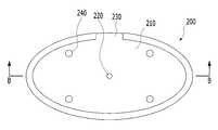
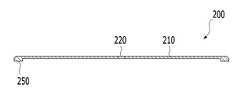
도 4a는 본 발명의 일 실시예에 따른 제2 조립체의 평면도 및 도 4b는 도 4a에 도시한 B-B선의 확대 단면도를 나타낸다.4A is a plan view of a second assembly according to an embodiment of the present invention, and FIG. 4B is an enlarged cross-sectional view taken along line B-B of FIG. 4A.
도 4a 및 도 4b를 참조하면, 제2 조립체(200)는 제1 조립체(100)의 상측으로 조립 가능하게 구성되고, 평판의 제2 조립 몸체(210), 빛을 집광하는 렌즈 투과공(220), 제2 조립 몸체(210)에 형성되는 제2 연통공(230) 및 제1 조립체(100)의 결합홈(150)과 결합되도록 제2 조립 몸체(210)의 하면에 형성되는 적어도 하나의 결합돌기(240)를 포함할 수 있다.4A and 4B, the
제2 조립 몸체(210)는 외부의 충격이나 오염으로부터 대상 체액을 보호할 수 있고, 대상 체액을 안정적으로 촬영할 수 있도록 합성수지 또는 금속 등과 같이 외부 충격에 강하고, 가벼운 물질로 이루어질 수 있다. 또한, 제2 조립 몸체(210)의 외면은 빛의 투과가 한정된 부분에서만 이루어질 수 있도록 비투과성 도료로 착색되거나 불투명 재료로 이루어질 수 있다.The
렌즈 투과공(220)은 좁은 수직 구멍으로서, 제2 조립 몸체(210)의 상측 중심에서 하측으로 관통될 수 있으며, 관통되는 제2 조립 몸체(210)의 상부면 주변은 검은색으로 도포될 수 있다. 이로써, 빛을 잘 흡수하는 검은색의 영향을 받아 좁은 구멍으로 더 많은 빛을 흡수할 수 있도록 한다.The
제2 연통공(230)은 제1 연통공(140)과 대응되는 위치에 제2 조립 몸체(210)의 테두리 부위를 관통하여 형성될 수 있다. 즉, 제2 연통공(230)은 관찰 시트(300)의 손잡이부(320)가 외부 공간에 배치되도록 제2 조립 몸체(210)에 형성될 수 있다. 보다 자세하게는, 하기에서 설명할 관찰 시트(300)의 손잡이부(320)가 안착될 수 있고, 손잡이부(320)의 단면에 대응하는 형상으로 이루어질 수 있다. 적어도 하나의 결합돌기(240)는 제2 조립 몸체(210)의 하면에 돌출 형성되어 적어도 하나의 결합홈(150)에 결합될 수 있다. 즉, 결합돌기(240)가 두 개일 경우, 제2 조립 몸체(210)의 하면 좌/우측에 각각 돌출 형성될 수 있고, 결합홈(150)에 대향하는 위치에 설치되어 제1 조립체(100)와 제2 조립체(200)의 결합 시 결합돌기(240)가 결합홈(150)에 각각 삽입될 수 있도록 한다.The
또한, 제2 조립체(200)는 제2 조립 몸체(210)의 바깥 테두리를 따라 단이지게 형성되어 제1 조립체(100)와의 결합에 따른 조립을 안내하는 제2 둘레 돌기(250)를 더 포함할 수 있다. 여기서, 제1 조립체(100)의 테두리에 설치되는 제1 둘레 단턱(170)과 제2 조립체(200)의 테두리에 설치되는 제2 둘레 돌기(250)가 상호 대응하여 결합 가능하게 설치될 수 있기 때문에 제1 조립체(100)와 제2 조립체(200)의 결합에 따른 위치의 조정 없이도 제1 조립체(100)와 제2 조립체(200)를 쉽게 조립할 수 있다.In addition, the
도 5는 본 발명의 일 실시예에 따른 관찰 시트의 평면도를 나타낸다.5 is a plan view of an observation sheet according to an embodiment of the present invention.
도 5를 참조하면, 관찰 시트(300)는 검사하고자 하는 대상 체액이 도포되고, 사용자 단말(10)의 카메라(11)가 대상 체액을 촬영할 수 있도록 하는 재물대의 역할을 한다. 이를 위해 관찰 시트(300)는 대상 체액을 수용하는 몸체부(310)와, 몸체부(310)로부터 연장되는 손잡이부(320)를 포함할 수 있다. 몸체부(310)는 일정한 양의 대상 체액을 수용할 수 있고, 얇은 판의 형태로 형성될 수 있다. 몸체부(310)는 광의 투과와 선명한 영상을 획득하기 위하여 투명한 재질 예컨대, 폴리카보네이트, 폴리에틸렌, 아크릴과 같은 합성수지 재질이나 유리 재질로 이루어질 수 있다. 또한, 몸체부(310)는 대상 체액이 선명하게 관찰될 수 있도록 단색 또는 대상 체액의 보색으로 채색되거나, 일면에 필름이 부착될 수도 있다.Referring to FIG. 5, the
몸체부(310)는 대상 체액이 투입되게 형성되는 체액 투입부(311) 및 체액 투입부(311)에 투입된 대상 체액이 확대렌즈(160)의 시야에서 관찰되도록 유도하는 체액 유도부(312)를 포함할 수 있다. 체액 투입부(311)는 대상 체액의 투입을 유도하도록 몸체부(310)에 형성되는 적어도 하나의 체액 가이드 홈(311a, 311b)을 포함할 수 있다. 예컨대, 체액 투입부(311)는 몸체부(310)의 좌/우측에 각각 형성되는 한 쌍의 체액 가이드 홈(311a, 311b)을 포함할 수 있다.The
체액 유도부(312)는 몸체부(310)의 중심부에 평판 형태로 삽입되어 체액 투입부(311)에 투입된 대상 체액을 보호하면서 대상 체액이 중심 안쪽으로 스며들어 확대렌즈(160)의 시야에서 관찰되도록 유도할 수 있다. 또한, 체액 유도부(312)는 체액 투입부(311)의 바닥보다 높게 형성되고, 제2 조립체(200)의 렌즈 투과공(220)과 일정한 간격을 유지할 수 있도록 한다. 한 쌍의 체액 가이드 홈(311a, 311b)에 대상 체액을 각각 떨어뜨리면, 대상 체액은 체액 가이드 홈(311a, 311b)에서 체액 유도부(312)의 중심 안쪽으로 스며들게 되는데, 이때 일정한 양의 대상 체액이 흡수되도록 체액 유도부(312)의 상면은 액체를 흡수할 수 있는 면, 종이 또는 다공성 합성수지와 같은 재질로 도포될 수 있다.The bodily
손잡이부(320)는 몸체부(310)로부터 연장되어 제1 조립체(100) 및 제2 조립체(200)의 외부 공간에 배치될 수 있다. 손잡이부(320)는 사용자가 파지할 수 있도록 구성되어 몸체부(310)를 제1 조립체(100)의 안착홈(120)에 용이하게 삽입하거나 이탈시킬 수 있다. 이때, 손잡이부(320)는 몸체부(310)와 동일한 재질로 형성될 수 있으나, 이에 한정되지는 않는다. 이와 같이, 관찰 시트(300)에 손잡이부(320)를 구현하여 사용자에 의해 대상 체액이 오염되는 것을 방지할 뿐만 아니라 체액 분석용 검사 장치(1)의 내부에 관찰 시트(300)를 용이하게 안착시키고 분리할 수 있다.The
또한, 손잡이부(320)에는 관찰 시트(300)의 투입 방향을 사용자가 용이하게 확인할 수 있도록 방향 표시 수단이 표시될 수 있다.In addition, a direction indicating means may be displayed on the
한편, 손잡이부(320)는 제1 조립체(100) 및 제2 조립체(200)의 내부 공간에 배치될 수도 있다. 즉, 안착홈(120)이 관찰 시트(300)의 평면과 동일한 형상으로 이루어진 경우, 손잡이부(320)는 몸체부(310)와 함께 제1 조립체(100) 및 제2 조립체(200)의 내측에 안착될 수 있다. 이와 같이, 몸체부(310) 및 손잡이부(320)가 제1 조립체(100) 및 제2 조립체(200)의 내부 공간에 배치될 경우, 제1 조립체(100) 및 제2 조립체(200)에는 제1 연통공(140) 및 제2 연통공(230)이 구비되지 않을 수 있다.Meanwhile, the
또 한편, 제1 조립체(100)는 사용자 단말(10)의 카메라(11)와 마주보는 방향에 관통공(130)이 위치하도록 설치하고, 제2 조립체(200)의 렌즈 투과공(220)을 통해 빛이 집광되도록 함으로써 관찰 시트(300)에 수용된 대상 체액을 확대렌즈(160)를 통하여 선명하게 관찰할 수 있게 한다.On the other hand, the
즉, 렌즈 투과공(220)을 통하여 빛을 집광시킬 수 있기 때문에 확대렌즈(160)로 들어오는 빛을 밝혀 관찰 시트(300)에서 관찰되는 대상 체액의 선명도 및 밝기를 높일 수 있으며, 이로 인해 사용자 단말(10)에서 선명한 영상이 표출될 수 있게 한다.That is, since light can be condensed through the
이하에서는 본 발명의 실시예에 따른 체액 분석용 검사 장치를 이용하여 대상 체액을 검사하는 과정에 대하여 예를 들어 설명하도록 한다.Hereinafter, a process of testing a target body fluid using the body fluid analysis test apparatus according to an embodiment of the present invention will be described by way of example.
먼저, 사용자 단말(10)의 카메라(11) 상측으로 체액 분석용 검사 장치(100)의 제1 조립체(100)를 거치하거나 부착한 후, 제1 조립체(100)의 안착홈(120)에 관찰 시트(300)를 안착시킨다.First, after mounting or attaching the
다음으로, 제1 조립체(100)에 안착된 관찰 시트(300)의 체액 투입부(311)에 대상 체액을 떨어뜨린 후, 제1 조립체(100)의 상측으로 제2 조립체(200)를 결합하여 조립을 마무리할 수 있다. 이때, 제1 조립체(100)의 안착홈(120)에 대상 체액이 수용된 관찰 시트(300)를 먼저 안착시킨 후, 관찰 시트가 안착된 제1 조립체(100)와 제2 조립체(200)를 결합하여 조립한 다음에 제1 조립체(100)와 제2 조립체(200)가 결합된 체액 분석용 검사 장치를 사용자 단말(10)에 거치하거나 부착시키는 것도 가능하다.Next, after dropping the target body fluid onto the body
그런 다음, 사용자 단말(10)의 체액 분석 검사 전용 프로그램이나 어플리케이션을 실행시켜 카메라(11)를 통해 관찰 시트(300)에 수용된 대상 체액을 관찰하여 촬영하는 것으로, 체액 분석 검사 과정을 수행할 수 있다.Then, by executing a program or application dedicated to the body fluid analysis test of the
이와 같이, 체액 분석용 검사 장치(1)는 사용자가 간편하게 휴대하면서도 실사용에서 간단하게 대상 체액만을 수집하여 검사 장치에 투입하는 것으로 사용자가 직접 체액 검사를 수행할 수 있도록 하고, 대상 체액을 분석한 결과를 사용자 단말을 통해 바로 확인할 수 있기 때문에 사용자에게 편리함과 정확한 검사 결과를 제공할 수 있다.In this way, the body fluid
이상에서 본 발명의 바람직한 실시예에 대하여 상세하게 설명하였지만 본 발명의 권리범위는 이에 한정되는 것은 아니고 다음의 청구범위에서 정의하고 있는 본 발명의 기본 개념을 이용한 당업자의 여러 변형 및 개량 형태 또한 본 발명의 권리범위에 속하는 것이다.Although the preferred embodiments of the present invention have been described in detail above, the scope of the present invention is not limited thereto, and various modifications and improvements by those skilled in the art using the basic concept of the present invention defined in the following claims are also present. It belongs to the scope of rights of
1: 체액 분석용 검사 장치
100: 제1 조립체
110: 제1 조립 몸체120: 안착홈
130: 관통공140: 제1 연통공
150: 결합홈160: 확대렌즈
170: 제1 둘레 단턱
200: 제2 조립체
210: 제2 조립 몸체220: 렌즈 투과공
230: 제2 연통공240: 결합돌기
250: 제2 둘레 돌기
300: 관찰 시트
310: 몸체부311: 체액 투입부
312: 체액 유도부320: 손잡이부1: Test device for body fluid analysis
100: first assembly
110: first assembly body 120: seating groove
130: through hole 140: first communication hole
150: coupling groove 160: magnifying lens
170: first circumferential stepped
200: second assembly
210: second assembly body 220: lens penetration hole
230: second communication hole 240: coupling protrusion
250: second circumferential protrusion
300: observation sheet
310: body part 311: body fluid input part
312: body fluid induction part 320: handle part
Claims (13)
Translated fromKorean상기 제1 조립체에 결합 가능하게 구성되고, 빛을 집광하는 렌즈 투과공이 구비되는 제2 조립체, 및
상기 제1 조립체 및 상기 제2 조립체 사이에서 상기 대상 체액을 수용하는 관찰 시트를 포함하고,
상기 관찰 시트는,
상기 제1 조립체 및 상기 제2 조립체의 내측에 배치되는 몸체부 및 상기 몸체부로부터 연장되는 손잡이부를 포함하고,
상기 제1 조립체는,
제1 조립 몸체,
상기 제1 조립 몸체의 내측에 상기 관찰 시트가 안착 가능하도록 형성되는 안착홈,
상기 안착홈에 형성되어 상기 제1 조립 몸체를 관통하는 관통공, 및
상기 제2 조립체와 조립 가능하도록 상기 제1 조립 몸체의 상면에 형성되는 적어도 하나의 결합홈을 더 포함하며,
상기 손잡이부는,
상기 제1 조립체 및 상기 제2 조립체의 외부 공간에 배치되고,
상기 제1 조립체는,
상기 안착홈과 외부 공간을 연통시키는 제1 연통공을 더 포함하며,
상기 제1 조립체는,
상기 제1 조립 몸체의 바깥 테두리를 따라 단이지게 형성되어 상기 제2 조립체와의 결합에 따른 조립을 안내하는 제1 둘레 단턱을 더 포함하고,
상기 제2 조립체는,
제2 조립 몸체, 및
상기 적어도 하나의 결합홈과 결합되도록 상기 제2 조립 몸체의 하면에 형성되는 적어도 하나의 결합돌기를 더 포함하며,
상기 제2 조립체는,
상기 관찰 시트의 손잡이부가 외부 공간에 배치되도록 상기 제2 조립 몸체에 형성되는 제2 연통공을 더 포함하고,
상기 제2 조립체는,
상기 제2 조립 몸체의 바깥 테두리를 따라 단이지게 형성되어 상기 제1 조립체와의 결합에 따른 조립을 안내하는 제2 둘레 돌기를 더 포함하며,
상기 몸체부는,
상기 대상 체액이 투입되게 형성되는 체액 투입부, 및
상기 체액 투입부에 투입된 상기 대상 체액이 상기 확대렌즈의 시야에서 관찰되도록 유도하는 체액 유도부를 포함하는 체액 분석용 검사 장치.A first assembly provided with a magnifying lens for magnifying and observing a target body fluid,
A second assembly coupled to the first assembly and provided with a lens penetration hole for condensing light, and
Including an observation sheet for accommodating the object body fluid between the first assembly and the second assembly,
The observation sheet,
A body portion disposed inside the first assembly and the second assembly, and a handle portion extending from the body portion,
The first assembly,
First assembly body,
A seating groove formed so that the observation sheet can be seated on the inside of the first assembly body,
A through hole formed in the seating groove and penetrating the first assembly body, and
Further comprising at least one coupling groove formed on the upper surface of the first assembly body to be assembled with the second assembly,
The handle part,
Disposed in the outer space of the first assembly and the second assembly,
The first assembly,
Further comprising a first communication hole for communicating the seating groove and the outer space,
The first assembly,
Further comprising a first circumferential stepped step formed along the outer rim of the first assembly body to guide assembly according to the coupling with the second assembly,
The second assembly,
A second assembly body, and
Further comprising at least one coupling protrusion formed on a lower surface of the second assembly body to be coupled to the at least one coupling groove,
The second assembly,
Further comprising a second communication hole formed in the second assembly body so that the handle portion of the observation sheet is disposed in the outer space,
The second assembly,
Further comprising a second circumferential protrusion formed stepwise along the outer edge of the second assembly body to guide the assembly according to the coupling with the first assembly,
The body part,
A bodily fluid input unit formed to be injected with the target bodily fluid, and
A body fluid analysis test apparatus comprising a body fluid guide unit for inducing the target body fluid injected into the body fluid input unit to be observed in a field of view of the magnifying lens.
상기 확대렌즈는,
상기 안착홈에 내설되는 체액 분석용 검사 장치.In claim 1,
The magnifying lens,
A test device for analyzing bodily fluids installed in the seating groove.
상기 렌즈 투과공은,
상기 제2 조립 몸체의 상측에서 하측으로 관통되는 체액 분석용 검사 장치.In claim 1,
The lens penetration hole,
Body fluid analysis test device that penetrates from the upper side to the lower side of the second assembly body.
상기 체액 투입부는,
상기 대상 체액의 투입을 유도하도록 상기 몸체부에 형성되는 적어도 하나의 체액 가이드 홈을 포함하는 체액 분석용 검사 장치.In claim 1,
The bodily fluid input unit,
Body fluid analysis test apparatus comprising at least one body fluid guide groove formed in the body portion to induce the injection of the target body fluid.
상기 제1 조립체는,
사용자 단말의 카메라에 탈부착 가능하게 설치되는 체액 분석용 검사 장치.In claim 1,
The first assembly,
A body fluid analysis test device that is detachably installed on the camera of the user terminal.
Priority Applications (7)
| Application Number | Priority Date | Filing Date | Title |
|---|---|---|---|
| KR1020180101355AKR102210306B1 (en) | 2018-08-28 | 2018-08-28 | Test Apparatus for Analysing Body Fluid |
| JP2021513733AJP7100197B2 (en) | 2018-08-28 | 2019-03-04 | Inspection device for body fluid analysis |
| US17/054,180US12329492B2 (en) | 2018-08-28 | 2019-03-04 | Test device for body fluid analysis |
| ES19854459TES2995115T3 (en) | 2018-08-28 | 2019-03-04 | Test device for body fluid analysis |
| CN201980030548.1ACN112105288A (en) | 2018-08-28 | 2019-03-04 | Body fluid analysis test device |
| EP19854459.5AEP3777655B1 (en) | 2018-08-28 | 2019-03-04 | Test device for body fluid analysis |
| PCT/KR2019/002460WO2020045778A1 (en) | 2018-08-28 | 2019-03-04 | Test device for body fluid analysis |
Applications Claiming Priority (1)
| Application Number | Priority Date | Filing Date | Title |
|---|---|---|---|
| KR1020180101355AKR102210306B1 (en) | 2018-08-28 | 2018-08-28 | Test Apparatus for Analysing Body Fluid |
Publications (2)
| Publication Number | Publication Date |
|---|---|
| KR20200024544A KR20200024544A (en) | 2020-03-09 |
| KR102210306B1true KR102210306B1 (en) | 2021-02-09 |
Family
ID=69643233
Family Applications (1)
| Application Number | Title | Priority Date | Filing Date |
|---|---|---|---|
| KR1020180101355AActiveKR102210306B1 (en) | 2018-08-28 | 2018-08-28 | Test Apparatus for Analysing Body Fluid |
Country Status (7)
| Country | Link |
|---|---|
| US (1) | US12329492B2 (en) |
| EP (1) | EP3777655B1 (en) |
| JP (1) | JP7100197B2 (en) |
| KR (1) | KR102210306B1 (en) |
| CN (1) | CN112105288A (en) |
| ES (1) | ES2995115T3 (en) |
| WO (1) | WO2020045778A1 (en) |
Families Citing this family (2)
| Publication number | Priority date | Publication date | Assignee | Title |
|---|---|---|---|---|
| USD976435S1 (en)* | 2021-04-23 | 2023-01-24 | Intin Co., Ltd. | Body fluid analyzer |
| KR102569696B1 (en)* | 2021-05-28 | 2023-08-24 | (주)에프피에이 | Kit for Urine Analysis |
Citations (1)
| Publication number | Priority date | Publication date | Assignee | Title |
|---|---|---|---|---|
| JP2017161301A (en)* | 2016-03-08 | 2017-09-14 | 株式会社リクルートホールディングス | Sperms simple test kit, system, and method for sperms simple test |
Family Cites Families (17)
| Publication number | Priority date | Publication date | Assignee | Title |
|---|---|---|---|---|
| US5104619A (en)* | 1990-01-24 | 1992-04-14 | Gds Technology, Inc. | Disposable diagnostic system |
| US6844149B2 (en) | 2001-06-29 | 2005-01-18 | International Business Machines Corporation | Method, system, and apparatus for measurement and recording of blood chemistry and other physiological measurements |
| JP2003287530A (en) | 2002-03-28 | 2003-10-10 | Fuji Photo Film Co Ltd | Humor test unit |
| US20080255472A1 (en) | 2007-04-13 | 2008-10-16 | Youti Kuo | Ovulation-prediction devices with image processing system |
| US9212995B2 (en)* | 2009-03-02 | 2015-12-15 | Mbio Diagnostics, Inc. | System and method for detecting multiple molecules in one assay |
| CN102053051A (en) | 2009-10-30 | 2011-05-11 | 西门子公司 | Body fluid analysis system as well as image processing device and method for body fluid analysis |
| KR101323373B1 (en) | 2011-07-26 | 2013-10-29 | 김수동 | A portable digital multi-reader to analyze urine, blood, Saliva and Biological secretions samples |
| KR101634541B1 (en)* | 2013-04-24 | 2016-07-05 | 연세대학교 산학협력단 | Cell-phone based strip sensor for measuring stress and depression |
| JP2015057626A (en) | 2013-08-16 | 2015-03-26 | 國昭 永山 | Lens unit and transmitted-light compound microscope device |
| BR112016011252B1 (en) | 2013-12-12 | 2020-11-24 | Mes Medical Electronic Systems Ltd | 0PTICO DEVICE, TESTING EQUIPMENT, SAMPLE SUPPORT AND TEST METHOD |
| KR101533107B1 (en) | 2014-11-14 | 2015-07-01 | (주)종로의료기 | Method for measuring ovulation using smartphone |
| CN107429285B (en)* | 2015-03-19 | 2021-10-15 | 3M创新有限公司 | Method, device and kit for detecting microorganisms in fluid sample |
| KR101813866B1 (en) | 2015-12-15 | 2018-01-02 | (주)종로의료기 | The test device for Body fluid analysis using natural light |
| TW201728955A (en)* | 2016-02-05 | 2017-08-16 | 億觀生物科技股份有限公司 | Optical viewing device |
| DE102016102867A1 (en) | 2016-02-18 | 2017-08-24 | Oculyze Gmbh | microscope arrangement |
| KR101994982B1 (en) | 2016-11-22 | 2019-07-01 | (주)인트인 | Portable test device for body fluid analysis |
| CN107144568B (en) | 2017-06-23 | 2023-06-20 | 深圳乐普智能医疗器械有限公司 | Sperm analysis device and analysis method thereof |
- 2018
- 2018-08-28KRKR1020180101355Apatent/KR102210306B1/enactiveActive
- 2019
- 2019-03-04CNCN201980030548.1Apatent/CN112105288A/enactivePending
- 2019-03-04WOPCT/KR2019/002460patent/WO2020045778A1/ennot_activeCeased
- 2019-03-04EPEP19854459.5Apatent/EP3777655B1/enactiveActive
- 2019-03-04JPJP2021513733Apatent/JP7100197B2/enactiveActive
- 2019-03-04USUS17/054,180patent/US12329492B2/enactiveActive
- 2019-03-04ESES19854459Tpatent/ES2995115T3/enactiveActive
Patent Citations (1)
| Publication number | Priority date | Publication date | Assignee | Title |
|---|---|---|---|---|
| JP2017161301A (en)* | 2016-03-08 | 2017-09-14 | 株式会社リクルートホールディングス | Sperms simple test kit, system, and method for sperms simple test |
Also Published As
| Publication number | Publication date |
|---|---|
| US20210186333A1 (en) | 2021-06-24 |
| EP3777655C0 (en) | 2024-10-16 |
| CN112105288A (en) | 2020-12-18 |
| EP3777655B1 (en) | 2024-10-16 |
| KR20200024544A (en) | 2020-03-09 |
| WO2020045778A1 (en) | 2020-03-05 |
| JP7100197B2 (en) | 2022-07-12 |
| EP3777655A4 (en) | 2021-06-23 |
| ES2995115T3 (en) | 2025-02-06 |
| EP3777655A1 (en) | 2021-02-17 |
| US12329492B2 (en) | 2025-06-17 |
| JP2021521468A (en) | 2021-08-26 |
Similar Documents
| Publication | Publication Date | Title |
|---|---|---|
| US7816124B2 (en) | Diagnostic whole blood and plasma apparatus | |
| EP2204440B1 (en) | Sperm analysis system | |
| US8206650B2 (en) | Joint-diagnostic spectroscopic and biosensor meter | |
| RU2194446C2 (en) | Method for following glucose contents in blood | |
| KR102210306B1 (en) | Test Apparatus for Analysing Body Fluid | |
| MX2007011104A (en) | A method, device and system for volumetric enumeration of white blood cells. | |
| EP3545853B1 (en) | Body fluid testing device having improved illumination | |
| US10730043B2 (en) | Sample collection and separation device | |
| KR101813867B1 (en) | The test device for body fluid analysis using light source | |
| KR101813866B1 (en) | The test device for Body fluid analysis using natural light | |
| WO2022158813A1 (en) | Specimen collection kit | |
| KR101920273B1 (en) | Sampler for body fluid analysis device and body fluid analysis device using the same | |
| KR101994982B1 (en) | Portable test device for body fluid analysis | |
| CN112113895A (en) | A blood cell analyzer | |
| CN219070318U (en) | Filter paper structure is adopted to blood | |
| KR200246866Y1 (en) | A immuno diagnostic kit for diagnosing of disease using membrane chromatographe and menstruation blood | |
| US10456068B2 (en) | Device for obtaining small, precise volumes of fluid from animals | |
| CA2523486A1 (en) | Joint-diagnostic spectroscopic and biosensor meter | |
| Zieminski et al. | Hematocrit measurement technology for use in low-resource environments utilizing a microfluidic disk with optical reader | |
| HK1143178B (en) | Sperm analysis system |
Legal Events
| Date | Code | Title | Description |
|---|---|---|---|
| A201 | Request for examination | ||
| PA0109 | Patent application | Patent event code:PA01091R01D Comment text:Patent Application Patent event date:20180828 | |
| PA0201 | Request for examination | ||
| E902 | Notification of reason for refusal | ||
| PE0902 | Notice of grounds for rejection | Comment text:Notification of reason for refusal Patent event date:20200205 Patent event code:PE09021S01D | |
| PG1501 | Laying open of application | ||
| E701 | Decision to grant or registration of patent right | ||
| PE0701 | Decision of registration | Patent event code:PE07011S01D Comment text:Decision to Grant Registration Patent event date:20201023 | |
| PR0701 | Registration of establishment | Comment text:Registration of Establishment Patent event date:20210126 Patent event code:PR07011E01D | |
| PR1002 | Payment of registration fee | Payment date:20210126 End annual number:3 Start annual number:1 | |
| PG1601 | Publication of registration | ||
| PR1001 | Payment of annual fee | Payment date:20211020 Start annual number:7 End annual number:9 Payment date:20211020 Start annual number:4 End annual number:6 |