KR102209543B1 - Method and system for monitoring hemodynamics - Google Patents
Method and system for monitoring hemodynamicsDownload PDFInfo
- Publication number
- KR102209543B1 KR102209543B1KR1020207002613AKR20207002613AKR102209543B1KR 102209543 B1KR102209543 B1KR 102209543B1KR 1020207002613 AKR1020207002613 AKR 1020207002613AKR 20207002613 AKR20207002613 AKR 20207002613AKR 102209543 B1KR102209543 B1KR 102209543B1
- Authority
- KR
- South Korea
- Prior art keywords
- signal
- subject
- output
- input
- hybrid
- Prior art date
- Legal status (The legal status is an assumption and is not a legal conclusion. Google has not performed a legal analysis and makes no representation as to the accuracy of the status listed.)
- Expired - Fee Related
Links
Images


Classifications
- A—HUMAN NECESSITIES
- A61—MEDICAL OR VETERINARY SCIENCE; HYGIENE
- A61B—DIAGNOSIS; SURGERY; IDENTIFICATION
- A61B5/00—Measuring for diagnostic purposes; Identification of persons
- A61B5/02—Detecting, measuring or recording for evaluating the cardiovascular system, e.g. pulse, heart rate, blood pressure or blood flow
- A61B5/0205—Simultaneously evaluating both cardiovascular conditions and different types of body conditions, e.g. heart and respiratory condition
- A—HUMAN NECESSITIES
- A61—MEDICAL OR VETERINARY SCIENCE; HYGIENE
- A61B—DIAGNOSIS; SURGERY; IDENTIFICATION
- A61B5/00—Measuring for diagnostic purposes; Identification of persons
- A61B5/02—Detecting, measuring or recording for evaluating the cardiovascular system, e.g. pulse, heart rate, blood pressure or blood flow
- A61B5/02007—Evaluating blood vessel condition, e.g. elasticity, compliance
- A—HUMAN NECESSITIES
- A61—MEDICAL OR VETERINARY SCIENCE; HYGIENE
- A61B—DIAGNOSIS; SURGERY; IDENTIFICATION
- A61B5/00—Measuring for diagnostic purposes; Identification of persons
- A61B5/02—Detecting, measuring or recording for evaluating the cardiovascular system, e.g. pulse, heart rate, blood pressure or blood flow
- A61B5/02028—Determining haemodynamic parameters not otherwise provided for, e.g. cardiac contractility or left ventricular ejection fraction
- A—HUMAN NECESSITIES
- A61—MEDICAL OR VETERINARY SCIENCE; HYGIENE
- A61B—DIAGNOSIS; SURGERY; IDENTIFICATION
- A61B5/00—Measuring for diagnostic purposes; Identification of persons
- A61B5/02—Detecting, measuring or recording for evaluating the cardiovascular system, e.g. pulse, heart rate, blood pressure or blood flow
- A61B5/024—Measuring pulse rate or heart rate
- A—HUMAN NECESSITIES
- A61—MEDICAL OR VETERINARY SCIENCE; HYGIENE
- A61B—DIAGNOSIS; SURGERY; IDENTIFICATION
- A61B5/00—Measuring for diagnostic purposes; Identification of persons
- A61B5/02—Detecting, measuring or recording for evaluating the cardiovascular system, e.g. pulse, heart rate, blood pressure or blood flow
- A61B5/026—Measuring blood flow
- A61B5/029—Measuring blood output from the heart, e.g. minute volume
- A—HUMAN NECESSITIES
- A61—MEDICAL OR VETERINARY SCIENCE; HYGIENE
- A61B—DIAGNOSIS; SURGERY; IDENTIFICATION
- A61B5/00—Measuring for diagnostic purposes; Identification of persons
- A61B5/02—Detecting, measuring or recording for evaluating the cardiovascular system, e.g. pulse, heart rate, blood pressure or blood flow
- A61B5/026—Measuring blood flow
- A61B5/0295—Measuring blood flow using plethysmography, i.e. measuring the variations in the volume of a body part as modified by the circulation of blood therethrough, e.g. impedance plethysmography
- A—HUMAN NECESSITIES
- A61—MEDICAL OR VETERINARY SCIENCE; HYGIENE
- A61B—DIAGNOSIS; SURGERY; IDENTIFICATION
- A61B5/00—Measuring for diagnostic purposes; Identification of persons
- A61B5/05—Detecting, measuring or recording for diagnosis by means of electric currents or magnetic fields; Measuring using microwaves or radio waves
- A61B5/053—Measuring electrical impedance or conductance of a portion of the body
- A61B5/0535—Impedance plethysmography
- A—HUMAN NECESSITIES
- A61—MEDICAL OR VETERINARY SCIENCE; HYGIENE
- A61B—DIAGNOSIS; SURGERY; IDENTIFICATION
- A61B5/00—Measuring for diagnostic purposes; Identification of persons
- A61B5/145—Measuring characteristics of blood in vivo, e.g. gas concentration or pH-value ; Measuring characteristics of body fluids or tissues, e.g. interstitial fluid or cerebral tissue
- A61B5/14535—Measuring characteristics of blood in vivo, e.g. gas concentration or pH-value ; Measuring characteristics of body fluids or tissues, e.g. interstitial fluid or cerebral tissue for measuring haematocrit
- A—HUMAN NECESSITIES
- A61—MEDICAL OR VETERINARY SCIENCE; HYGIENE
- A61B—DIAGNOSIS; SURGERY; IDENTIFICATION
- A61B5/00—Measuring for diagnostic purposes; Identification of persons
- A61B5/24—Detecting, measuring or recording bioelectric or biomagnetic signals of the body or parts thereof
- A61B5/316—Modalities, i.e. specific diagnostic methods
- A61B5/318—Heart-related electrical modalities, e.g. electrocardiography [ECG]
- A61B5/346—Analysis of electrocardiograms
- A61B5/349—Detecting specific parameters of the electrocardiograph cycle
- A—HUMAN NECESSITIES
- A61—MEDICAL OR VETERINARY SCIENCE; HYGIENE
- A61B—DIAGNOSIS; SURGERY; IDENTIFICATION
- A61B5/00—Measuring for diagnostic purposes; Identification of persons
- A61B5/41—Detecting, measuring or recording for evaluating the immune or lymphatic systems
- A61B5/412—Detecting or monitoring sepsis
- A—HUMAN NECESSITIES
- A61—MEDICAL OR VETERINARY SCIENCE; HYGIENE
- A61B—DIAGNOSIS; SURGERY; IDENTIFICATION
- A61B5/00—Measuring for diagnostic purposes; Identification of persons
- A61B5/48—Other medical applications
- A61B5/4806—Sleep evaluation
- A61B5/4818—Sleep apnoea
- A—HUMAN NECESSITIES
- A61—MEDICAL OR VETERINARY SCIENCE; HYGIENE
- A61B—DIAGNOSIS; SURGERY; IDENTIFICATION
- A61B5/00—Measuring for diagnostic purposes; Identification of persons
- A61B5/48—Other medical applications
- A61B5/4836—Diagnosis combined with treatment in closed-loop systems or methods
- A—HUMAN NECESSITIES
- A61—MEDICAL OR VETERINARY SCIENCE; HYGIENE
- A61B—DIAGNOSIS; SURGERY; IDENTIFICATION
- A61B5/00—Measuring for diagnostic purposes; Identification of persons
- A61B5/48—Other medical applications
- A61B5/4869—Determining body composition
- A61B5/4875—Hydration status, fluid retention of the body
- A—HUMAN NECESSITIES
- A61—MEDICAL OR VETERINARY SCIENCE; HYGIENE
- A61B—DIAGNOSIS; SURGERY; IDENTIFICATION
- A61B5/00—Measuring for diagnostic purposes; Identification of persons
- A61B5/72—Signal processing specially adapted for physiological signals or for diagnostic purposes
- A61B5/7228—Signal modulation applied to the input signal sent to patient or subject; Demodulation to recover the physiological signal
- A—HUMAN NECESSITIES
- A61—MEDICAL OR VETERINARY SCIENCE; HYGIENE
- A61B—DIAGNOSIS; SURGERY; IDENTIFICATION
- A61B5/00—Measuring for diagnostic purposes; Identification of persons
- A61B5/72—Signal processing specially adapted for physiological signals or for diagnostic purposes
- A61B5/7235—Details of waveform analysis
- A61B5/7239—Details of waveform analysis using differentiation including higher order derivatives
- A—HUMAN NECESSITIES
- A61—MEDICAL OR VETERINARY SCIENCE; HYGIENE
- A61B—DIAGNOSIS; SURGERY; IDENTIFICATION
- A61B8/00—Diagnosis using ultrasonic, sonic or infrasonic waves
- A61B8/06—Measuring blood flow
- A61B8/065—Measuring blood flow to determine blood output from the heart
Landscapes
- Health & Medical Sciences (AREA)
- Life Sciences & Earth Sciences (AREA)
- Engineering & Computer Science (AREA)
- Physics & Mathematics (AREA)
- Medical Informatics (AREA)
- Pathology (AREA)
- Biomedical Technology (AREA)
- Heart & Thoracic Surgery (AREA)
- Molecular Biology (AREA)
- Surgery (AREA)
- Animal Behavior & Ethology (AREA)
- General Health & Medical Sciences (AREA)
- Public Health (AREA)
- Veterinary Medicine (AREA)
- Biophysics (AREA)
- Cardiology (AREA)
- Physiology (AREA)
- Hematology (AREA)
- Nuclear Medicine, Radiotherapy & Molecular Imaging (AREA)
- Radiology & Medical Imaging (AREA)
- Signal Processing (AREA)
- Artificial Intelligence (AREA)
- Psychiatry (AREA)
- Computer Vision & Pattern Recognition (AREA)
- Vascular Medicine (AREA)
- Immunology (AREA)
- Pulmonology (AREA)
- Optics & Photonics (AREA)
- Measuring Pulse, Heart Rate, Blood Pressure Or Blood Flow (AREA)
- Measurement And Recording Of Electrical Phenomena And Electrical Characteristics Of The Living Body (AREA)
- Measurement Of The Respiration, Hearing Ability, Form, And Blood Characteristics Of Living Organisms (AREA)
- Measuring And Recording Apparatus For Diagnosis (AREA)
Abstract
Translated fromKoreanDescription
Translated fromKorean관련 출원Related application
본 출원은 2011년 7월 25일에 출원된, 미국 임시 특허 출원 번호 61/511,163의 우선권의 이익을 청구하며, 그 내용은 그 전체로 참조함으로써 본 발명에 편입된다.This application claims the benefit of the priority of US Provisional Patent Application No. 61/511,163, filed on July 25, 2011, the contents of which are incorporated herein by reference in their entirety.
발명의 분야 및 배경Field and background of the invention
본 발명은, 이의 특정 구체예에서, 의학 분야에 관한 것으로, 더욱 상세하게는, 그러나 배타적이지는 않게, 혈류 역학 감시 방법 및 시스템에 관한 것이다.The present invention, in certain embodiments thereof, relates to the field of medicine, and more particularly, but not exclusively, to methods and systems for monitoring hemodynamics.
심장 질환은 현대에서 이환 및 사망의 중요 원인이다. 일반적으로, 심장 질환은 (i) 중추 신경계 제어로부터 심장 근육으로의 맥동이 규칙적 심장 박동을 제공하는 데 실패하게 되는 자율신경계 부전 및/또는 (ii) 비록 환자가 규칙적 심장 박동을 가지지만, 그 수축력이 불충분한 심근 자체의 불충분한 강도에 의해 야기될 수 있다. 어느 쪽이든, 혈액의 양, 또는 혈액이 이환된 심장에 의해 공급되는 속도가 비정상적이며, 및 환자의 혈류 상태의 평가는 매우 중요하다고 이해된다.Heart disease is a major cause of morbidity and death in modern times. In general, heart disease is characterized by (i) autonomic failure in which the pulsation from the central nervous system control to the heart muscle fails to provide a regular heart rate, and/or (ii) its contractile force, although the patient has a regular heart rate. This can be caused by insufficient strength of the myocardium itself. Either way, it is understood that the amount of blood, or the rate at which blood is supplied by the affected heart, is abnormal, and the evaluation of the patient's blood flow status is of great importance.
심장 박동 및 혈압과 같이, 가장 간단한 측정치들은 많은 환자들에게 적정할 수 있지만, 만약 심혈관적 비정상이 있다면 더 많은 상세한 측정치들이 필요하다.The simplest measurements, such as heart rate and blood pressure, may be appropriate for many patients, but more detailed measurements are needed if there are cardiovascular abnormalities.
심박출량(CO)은 일정 시간, 통상 일 분 동안 심장에 의해 펌프된 혈액의 부피이다. 심박출량은 심박수와, 1회 박출량(stroke volume SV)으로 알려진 각 심장박동으로 펌프된 혈액의 양을 곱한 것이다. 예를 들어, 기립 자세에서 휴면시 1회 박출량은 대부분 성인에서 평균 60 내지 80 ml이다. 따라서, 분당 80 심박의 휴면 심박수에서, 휴면 심박출량은 분당 4.8 내지 6.4 L 사이이다.Cardiac output (CO) is the volume of blood pumped by the heart over a period of time, usually one minute. Cardiac output is the product of the heart rate and the amount of blood pumped into each heartbeat, known as stroke volume SV. For example, the average ejection amount per dormant in a standing position is 60 to 80 ml in most adults. Thus, at a dormant heart rate of 80 hearts per minute, the dormant cardiac output is between 4.8 and 6.4 L per minute.
현재 몇 가지 심박출량을 측정하는 방법이 알려져 있다.Currently, several methods of measuring cardiac output are known.
하나의 그러한 방법은 심장의 다양한 구조적 및 기능적 이상을 진단하고 감시하는 상호식도 초음파 심장검진법(TOE)을 사용한다. TOE는 적혈구 세포로부터 반사된 초음파의 도플러 천이를 기록함으로써 혈류 속도의 측정치로부터 심박출량을 유도하는 데 사용한다. 하나의 심장 주기 동안 순간 혈류 속도의 적분인, 시간 속도 적분은 특정 부위(예, 좌심실 유출로)에서의 혈류에 대하여 얻어진다. 상기 시간 속도 적분을 단면적과 심박수로 곱하여 심박출량을 산출한다.One such method uses interactive echocardiography (TOE), which diagnoses and monitors various structural and functional abnormalities in the heart. The TOE is used to derive cardiac output from measurements of blood flow velocity by recording the Doppler transition of ultrasound reflected from red blood cells. The time velocity integral, the integral of the instantaneous blood flow velocity during one cardiac cycle, is obtained for blood flow at a specific site (eg, left ventricular outflow tract). The cardiac output is calculated by multiplying the time velocity integral by the cross-sectional area and the heart rate.
미국 특허 번호 제6,485,431호는 압력 커프(cuff) 또는 안압계(tonometer)에 의해 측정된 동맥압을 사용하여 심장이완시 동맥계의 평균 동맥압과 시간 정수를 계산하는 기술을 개시하고 있다. 다음, 동맥계의 순응도를 표로부터 결정하고, 이를 사용하여 시간 상수로 나눈 평균 동맥압 및 순응도의 곱으로서 심박출량을 계산한다.U.S. Patent No. 6,485,431 discloses a technique for calculating the mean arterial pressure and time constant of the arterial system during cardiac relaxation using arterial pressure measured by a pressure cuff or tonometer. Next, the compliance of the arterial system is determined from the table, and cardiac output is calculated as the product of the average arterial pressure divided by the time constant and the compliance using this.
심박출량을 측정하는 추가의 방법은 열희석법으로 알려져 있다. 이러한 방법은 심박출량을 혈액으로부터 상이한 온도에 있는 식염수의 볼러스의 희석으로부터 측정할 수 있는 원리에 기초하고 있다. 열희석법은 심장을 통해서 정맥으로 및 폐 동맥으로 가느다란 카테터를 삽입하는 것을 포함한다. 상기 카테터의 끝에 적재된 서미스터는 폐동맥에서 온도를 감지한다. 식염수의 볼러스(약 5 ml 부피)는 심장 우심방 내에 또는 근처에 위치한 카테터 내의 개구부를 통해 빠르게 주입된다. 이 식염수는 심장에서 혈액과 섞이고 일시적으로 우심방의 온도를 낮춘다. 2개의 온도가 동시에 측정된다: 상기 혈액 온도는 카테터 상의 서미스터 센서에 의해 측정되고 및 주입될 식명뭇의 온도는 백금 온도 센서에 의해 측정된다. 심박출량은 온도 감소 곡선하의 면적과 역관계에 있다.An additional method of measuring cardiac output is known as thermal dilution. This method is based on the principle that cardiac output can be determined from the dilution of a bolus of saline at different temperatures from the blood. Thermal dilution involves the insertion of a slender catheter through the heart into a vein and into a pulmonary artery. The thermistor mounted at the end of the catheter senses the temperature in the pulmonary artery. A saline bolus (approximately 5 µml volume) is rapidly injected through an opening in the catheter located in or near the right atrium of the heart. This saline solution mixes with blood in the heart and temporarily cools the right atrium. Two temperatures are measured simultaneously: the blood temperature is measured by a thermistor sensor on the catheter and the temperature of the plant to be injected is measured by a platinum temperature sensor. Cardiac output is inversely related to the area under the temperature decline curve.
흉부 전기 생체임피던스로 알려진, 비침습적 방법이 미국 특허 번호 3,340,867에 처음 개시되어 있고, 최근 의학적 및 산업적 관심을 끌기 시작했다 (참고, 예, 미국 특허 번호 3,340,867호, 4,450,527, 4,852,580, 4,870,578, 4,953,556, 5,178,154, 5,309,917, 5,316,004, 5,505,209, 5,529,072, 5,503,157, 5,469,859, 5,423,326, 5,685,316, 6,485,431, 6,496,732 및 6,511,438; 미국 특허 출원 번호 20020193689]. 흉부 전기 생체 임피던스 방법은 환자에게 아무런 위험없이 연속적인 심박출량 측정을 제공하는 장점을 가진다.A non-invasive method, known as thoracic electrical bioimpedance, was first disclosed in U.S. Patent No. 3,340,867 and recently began to attract medical and industrial interest (see, e.g., U.S. Patent Nos. 3,340,867, 4,450,527, 4,852,580, 4,870,578, 4,953,556, 5,178,154. , 5,309,917, 5,316,004, 5,505,209, 5,529,072, 5,503,157, 5,469,859, 5,423,326, 5,685,316, 6,485,431, 6,496,732 and 6,511,438; U.S. Patent Application Nos. 20020193689]. Have.
생체 임피던스를 사용하는 다양한 방법들은 국제 특허 공개 번호: WO2004098376, WO2006087696, WO2008129535, WO2009022330 및 WO2010032252에서 발견되고, 이들 모두는 본 발명의 공통적인 양수인에 귀속되며 참조함으로써 완전히 편입된다.Various methods of using bioimpedance are found in International Patent Publication Nos: WO2004098376, WO2006087696, WO2008129535, WO2009022330 and WO2010032252, all of which belong to the common assignee of the present invention and are fully incorporated by reference.
미국 특허 번호 4,926,868는 흉부 심혈관 구조물 특히 심실을 통해 전파되고 및 이에 의해 산란되는 마이크로파의 복소체 진폭(complex field amplitude)에 기반한 심장 혈류역학을 심장 주기 동안의 시간의 함수로서 개시하고 있다. 운동 인공구조물 및 신호 누출은 UHF 대역에서 작동하는, 밀접하게 연계되고, 유연하고, 경량이며, 부동태화되어 있는 등각 마이크로스트립 안테나들을 사용하여 조절된다. 기본적인 측정 기술은 뒤쪽에서 앞쪽(PA), 좌전사위(left anterior oblique, LAO), 및 우전사위(right anterior oblique, RAO)와 같은 다양한 투사의 전방 분산 형상에서의 지수 파 산란 매개변수의 벡터 네트워크 분석이다.U.S. Patent No. 4,926,868 discloses cardiac hemodynamics based on the complex field amplitude of the thoracic cardiovascular structures, particularly the microwaves propagating through and scattering through the ventricles, as a function of time during the cardiac cycle. Motion artifacts and signal leakage are controlled using tightly coupled, flexible, lightweight, and passivated conformal microstrip antennas operating in the UHF band. The basic measurement technique is a vector network analysis of exponential wave scattering parameters in various anterior dispersion shapes of projections such as posterior to anterior (PA), left anterior oblique (LAO), and right anterior oblique (RAO). to be.
미국 특허 공개 출원 번호 20020062086는 살아있는 유기체의 순환계와 연계된 하나 이상의 혈류역학 매개변수를 평가하는 비침습적 기술을 개시하고 있다. 혈류역학 매개변수는, 상기 변수의 비계량적 값을 비침습적으로 측정하고, 및 제1 매개변수를 측정하면서 상기 순환계에 스트레스를 유도함으로써 측정된다. 상기 순환계의 스트레스에 대한 반응은 대상자로부터 직접 결정되고, 및 상기 반응으로부터 검량 함수를 유도하고 상기 비계량의 측정치에 적용하여 상기 혈류역학 매개변수의 실제 값의 계량된 측정치를 산출한다.US Patent Published Application No. 20020062086 discloses a non-invasive technique for evaluating one or more hemodynamic parameters associated with the circulatory system of a living organism. The hemodynamic parameter is measured by non-invasively measuring the non-quantitative value of the variable, and by inducing stress on the circulatory system while measuring the first parameter. The response of the circulatory system to stress is determined directly from the subject, and a calibration function is derived from the response and applied to the measurement of the specific measurement to yield a metered measure of the actual value of the hemodynamic parameter.
미국 특허 공개 출원 번호 20090287102는 임피던스 분석을 사용하여 환자에서 종아리 근육 펌프(CMP) 기능을 측정하는 것을 개시하고 있다. 전기 신호는 제1 세트의 전극을 통해 적용되고, 임피던스는 제2 세트의 전극을 통해 측정된다. 환자가 종아리 신장 또는 운동함에 따라 임피던스에서의 변화가 측정되고, 및 임피던스에서의 변화를 사용하여 CMP 기능을 평가한다. 임피던스에서의 변화를 사용하여 CMP에 의해 분출되는 혈액 부피를 나타내는 지시물을 결정한다.US Patent Published Application No. 20090287102 discloses measuring calf muscle pump (CMP) function in a patient using impedance analysis. The electrical signal is applied through the first set of electrodes, and the impedance is measured through the second set of electrodes. Changes in impedance are measured as the patient stretches or exercises the calf, and changes in impedance are used to evaluate CMP function. The change in impedance is used to determine the indicator representing the volume of blood expelled by the CMP.
본 발명의 특정 구체예의 일 관점에 따라서, 대상자의 혈류역학을 감시하는 시스템을 제공한다. 상기 시스템은 적어도 하나의 출력 전기 신호를 제공하고 및 상기 출력 신호를 대상자의 기관에 전달하도록 구성된 신호 발생 시스템을 포함한다. 상기 시스템은 또한 상기 출력 전기 신호에 응답하게 기관으로부터 감지된 입력 전기 신호를 수신하고 및 상기 출력 신호를 사용하여 상기 입력 신호를 변조하여 상기 입력신호의 동상분 및 직각 성분을 제공하도록 구성된다. 상기 시스템은 또한 동상 및 직각 성분에 기초하여 혈류역학을 감시하도록 구성된 처리 시스템을 포함한다.According to one aspect of a specific embodiment of the present invention, a system for monitoring the hemodynamics of a subject is provided. The system includes a signal generation system configured to provide at least one output electrical signal and communicate the output signal to the subject's organ. The system is also configured to receive an input electrical signal sensed from an engine in response to the output electrical signal and use the output signal to modulate the input signal to provide in-phase and quadrature components of the input signal. The system also includes a processing system configured to monitor the hemodynamics based on the in-phase and orthogonal components.
본 발명의 특정 구체예의 일 관점에 따라서, 대상자의 혈류역학을 감시하는 방법을 제공한다. 상기 방법은 적어도 출력 전기 신호를 발생시키는 단계 및 상기 대상자의 기관에 상기 출력 신호를 전달하는 단계를 포함한다. 상기 방법은 또한 상기 출력 전기 신호에 반응하여 상기 기관으로부터 입력 전기 신호를 감지하는 단계, 및 상기 출력 신호를 사용하여 상기 입력 신호를 변조하여 상기 입력 신호의 동상분 및 직각 성분을 제공하는 단계를 더 포함한다. 상기 방법은 또한 상기 동상분 및 직각 성분에 기초하여 혈류역학을 감시하는 단계를 더 포함한다.According to one aspect of a specific embodiment of the present invention, a method of monitoring the hemodynamics of a subject is provided. The method includes at least generating an output electrical signal and passing the output signal to the subject's organ. The method further comprises detecting an input electrical signal from the engine in response to the output electrical signal, and modulating the input signal using the output signal to provide in-phase and right angle components of the input signal. Include. The method further includes monitoring hemodynamics based on the frostbite and quadrature component.
본 발명의 특정 구체예에 따라서, 상기 처리 시스템 및/또는 방법은 상기 동상분을 상기 직각 성분과 조합하여 하이브리드 신호를 생성하고, 상기 감시는 상기 하이브리드 신호에 적어도 부분적으로 기초한다.According to a specific embodiment of the invention, the processing system and/or method combines the in-phase component with the quadrature component to generate a hybrid signal, and the monitoring is based at least in part on the hybrid signal.
본 발명의 특정 구체예에 따라서, 상기 신호 발생 시스템 및/또는 방법은 제1 출력 전기 신호 및 제2 출력 전기 신호를 제공하고, 및 상기 출력 신호 각각을 기관의 분리된 부분에 전달한다. 본 발명의 특정 구체예에 따라서, 상기 복조 시스템 및/또는 각각의 출력 전기 신호에 반응적으로 상기 기관의 각 부분으로부터 감지된 입력 전기 신호를 수신하고, 그 신호들을 변조하여 상기 입력 신호 각각의 동상분 및 직각 성분을 제공한다.According to a specific embodiment of the invention, the signal generation system and/or method provides a first output electrical signal and a second output electrical signal, and passes each of the output signals to a separate part of the engine. According to a specific embodiment of the present invention, in response to the demodulation system and/or each output electric signal, the input electric signal sensed from each part of the organ is received, and the signals are modulated to obtain the in-phase of each of the input signals. Provides minute and right angle components.
본 발명의 특정 구체예에 따라서 상기 처리 시스템 및/또는 방법은 각 입력 신호에 대하여, 각각의 동상분과 각각의 직각 성분을 조합하여 상기 입력 신호에 상응하는 하이브리드 신호를 발생시킨다. 본 발명의 특정 구체예에 따라서 상기 감시는 상기 하이브리드 신호에 적어도 부분적으로 기반하고 있다.According to a specific embodiment of the present invention, the processing system and/or method combines, for each input signal, each in-phase component and each square component to generate a hybrid signal corresponding to the input signal. According to a specific embodiment of the invention the monitoring is based at least in part on the hybrid signal.
본 발명의 특정 구체예에 따라서, 상기 처리 시스템 및/또는 방법은 상기 하이브리드 신호를 조합함으로써 조합된 하이브리드 신호를 제공하고, 및 여기서 상기 감시는 상기 조합된 하이브리드 신호에 적어도 부분적으로 기반한다.According to a specific embodiment of the invention, the processing system and/or method provides a combined hybrid signal by combining the hybrid signals, wherein the monitoring is based at least in part on the combined hybrid signal.
본 발명의 특정 구체예에 따라서 상기 처리 시스템 및/또는 방법은 제1 입력 신호의 동상분과 제2 입력신호의 동상분과 조합하여 조합된 동상 신호를 제공한다. 본 발명의 특정 구체예에 따라서, 상기 감시는 상기 조합된 동상 신호에 적어도 부분적으로 기반한다.According to a specific embodiment of the present invention, the processing system and/or method combines the in-phase component of the first input signal and the in-phase component of the second input signal to provide a combined in-phase signal. According to a specific embodiment of the invention, the monitoring is based at least in part on the combined in-phase signal.
본 발명의 특정 구체예에 따라서 상기 처리 시스템 및/또는 방법은 제1 입력신호의 직각 성분과 제2 입력 신호의 직각 성분을 조합하여 조합된 직각 신호를 제공한다. 본 발명의 특정 구체예에 따라서 상기 감시는 상기 조합된 직각 신호에 적어도 부분적으로 기반한다.According to certain embodiments of the present invention, the processing system and/or method combines the right angle component of the first input signal and the right angle component of the second input signal to provide a combined right angle signal. According to a specific embodiment of the invention the monitoring is based at least in part on the combined rectangular signal.
본 발명의 특정 구체예에 따라서, 상기 처리 시스템 및/또는 방법은, 각 입력 신호에 대하여, 위상 성분, 진폭 성분, 및 상기 위상 성분과 상기 진폭 성분과의 조합으로서 정의된 위상-진폭 성분 하이브리드를 계산한다. 본 발명의 특정 구체예에 따라서, 상기 감시는 이러한 조합에 적어도 부분적으로 기반한다.According to a specific embodiment of the invention, the processing system and/or method comprises, for each input signal, a phase component, an amplitude component, and a phase-amplitude component hybrid defined as a combination of the phase component and the amplitude component. Calculate. According to a specific embodiment of the invention, the monitoring is based at least in part on this combination.
본 발명의 특정 구체예에 따라서, 상기 처리 시스템 및/또는 방법은 제1 입력 신호에 상응하는 위상-진폭 하이브리드 신호를 상기 제2 입력 신호에 상응하는 위상-진폭 하이브리드 신호와 조합하여 조합된 위상-진폭 하이브리드 신호를 제공한다. 본 발명의 특정 구체예에 따라서 상기 감시는 상기 조합된 위상-진폭 하이브리드 신호에 적어도 부분적으로 기반한다.According to a specific embodiment of the present invention, the processing system and/or method comprises combining a phase-amplitude hybrid signal corresponding to a first input signal with a phase-amplitude hybrid signal corresponding to the second input signal to provide a combined phase- Provides an amplitude hybrid signal. According to a specific embodiment of the invention the monitoring is based at least in part on the combined phase-amplitude hybrid signal.
본 발명의 특정 구체예의 일 관점에 따라서, 대상자의 혈류역학을 감시하는 시스템을 제공한다. 상기 시스템은 제1 출력 전기 신호 및 제2 출력 전기 신호를 제공하고, 및 출력 신호 각각을 상기 대상자의 기관의 개별 부분에 전달하도록 구성된 신호 발생 시스템을 포함한다. 상기 시스템은 각각의 출력 전기 신호에 상응하여 상기 기관의 각 부분으로부터 감지된 입력 전기 신호를 수신하도록 및 입력 전기 신호에 기반하여 혈류 역학을 감시하도록 구성된 처리 시스템을 더 포함한다.According to one aspect of a specific embodiment of the present invention, a system for monitoring the hemodynamics of a subject is provided. The system includes a signal generation system configured to provide a first output electrical signal and a second output electrical signal, and deliver each of the output signals to a separate portion of the subject's organ. The system further includes a processing system configured to receive input electrical signals sensed from each part of the organ in response to each output electrical signal and to monitor hemodynamics based on the input electrical signal.
본 발명의 특정 구체예의 일 관점에 따라서 대상자의 혈류역학을 감시하는 방법을 제공한다. 상기 방법은: 제1 출력 전기 신호 및 제2 출력 전기 신호를 발생시키는 단계, 및 상기 출력 신호들 각각을 상기 대상자의 기관의 개별 부분에 전달하는 단계를 포함한다. 상기 방법은 각각의 출력 전기 신호에 반응하여 상기 기관의 각 부분으로부터 입력 전기 신호를 감지하는 단계, 및 입력 전기 신호들에 기반하여, 상기 혈류 역학을 감시하는 단계를 더 포함한다.In accordance with one aspect of a specific embodiment of the present invention, a method of monitoring the hemodynamics of a subject is provided. The method includes: generating a first output electrical signal and a second output electrical signal, and passing each of the output signals to a separate portion of the subject's organ. The method further includes sensing an input electrical signal from each part of the organ in response to each output electrical signal, and monitoring the hemodynamics based on the input electrical signals.
본 발명의 특정 구체예에 따라서, 상기 시스템 및/또는 방법은 상기 입력 신호들을 조합하여 조합된 신호를 제공하며, 여기서, 상기 감시는 상기 조합된 신호에 적어도 부분적으로 기반한다.According to a specific embodiment of the invention, the system and/or method combines the input signals to provide a combined signal, wherein the monitoring is based at least in part on the combined signal.
본 발명의 특정 구체예에 따라서, 상기 신호 조합들의 임의의 것은 선형 조합이다.According to a specific embodiment of the invention, any of the above signal combinations is a linear combination.
본 발명의 특정 구체예에 따라서, 상기 신호 조합들의 임의의 것은 비선형 조합이다.According to a specific embodiment of the invention, any of the above signal combinations is a non-linear combination.
본 발명의 특정 구체예에 따라서, 상기 처리 시스템 및/또는 방법은 상기 조합된 하이브리드 신호 및/또는 상기 조합된 위상-진폭 하이브리드 신호 및/또는 상기 조합된 신호에 기반하여, 1회 박출량(SV), 심박출량(CO), 심실 분출 시간(VET), 심계수(CI), 흉부 유체 함량(TFC), 총 말초 저항 계수(TPRI), 및 혈관 탄성도로 구성되는 군으로부터 선택된 적어도 하나의 특성을 평가한다.According to a specific embodiment of the invention, the processing system and/or method comprises a stroke amount (SV) based on the combined hybrid signal and/or the combined phase-amplitude hybrid signal and/or the combined signal. , Cardiac output (CO), ventricular ejection time (VET), heart coefficient (CI), chest fluid content (TFC), total peripheral resistance coefficient (TPRI), and at least one characteristic selected from the group consisting of vascular elasticity do.
본 발명의 특정 구체예에 따라서 상기 처리 시스템 및/또는 방법은 상기 조합된 하이브리드 신호 및/또는 상기 조합된 위상-진폭 하이브리드 신호 및/또는 상기 조합된 신호에 기반하여, 대상자의 운동능력을 평가한다.According to certain embodiments of the present invention, the processing system and/or method evaluates the motor capacity of the subject based on the combined hybrid signal and/or the combined phase-amplitude hybrid signal and/or the combined signal. .
본 발명의 특정 구체예에 따라서 상기 처리 시스템 및/또는 방법은 상기 조합된 하이브리드 신호 및/또는 상기 조합된 위상-진폭 하이브리드 신호 및/또는 상기 조합된 신호에 기반하여, 수면 무호흡 증상을 확인한다.According to certain embodiments of the present invention, the processing system and/or method identifies sleep apnea symptoms based on the combined hybrid signal and/or the combined phase-amplitude hybrid signal and/or the combined signal.
본 발명의 특정 구체예에 따라서 상기 처리 시스템 및/또는 방법은 상기 조합된 하이브리드 신호 및/또는 상기 조합된 위상-진폭 하이브리드 신호 및/또는 상기 조합된 신호에 기반하여 상기 대상자가 패혈증을 발전시킬 가능성을 산정한다.According to certain embodiments of the present invention, the processing system and/or method provides the possibility that the subject develops sepsis based on the combined hybrid signal and/or the combined phase-amplitude hybrid signal and/or the combined signal. Calculate
본 발명의 특정 구체예에 따라서 상기 처리 시스템 및/또는 방법은 상기 조합된 하이브리드 신호 및/또는 상기 조합된 위상-진폭 하이브리드 신호 및/또는 상기 조합된 신호에 기반하여 전자기계적 해리의 개시를 예측한다.According to certain embodiments of the present invention, the processing system and/or method predicts the onset of electromechanical dissociation based on the combined hybrid signal and/or the combined phase-amplitude hybrid signal and/or the combined signal. .
본 발명의 특정 구체예에 따라서 상기 처리 시스템 및/또는 방법 상기 조합된 하이브리드 신호 및/또는 상기 조합된 위상-진폭 하이브리드 신호 및/또는 상기 조합된 신호에 기반하여 혈액 적혈구 용적율을 평가한다.According to a specific embodiment of the present invention, the processing system and/or method is based on the combined hybrid signal and/or the combined phase-amplitude hybrid signal and/or the combined signal to assess blood red blood cell volume fraction.
본 발명의 특정 구체예에 따라서 상기 제1 및 제2 출력 전기 신호들은 의존적 전기 신호이다.According to a specific embodiment of the invention the first and second output electrical signals are dependent electrical signals.
본 발명의 특정 구체예에 따라서, 상기 제1 및 제2 출력 전기 신호들은 의존적 전기 신호이다.According to a specific embodiment of the invention, the first and second output electrical signals are dependent electrical signals.
별다르게 정의되지 않는 한, 본 명세서에서 사용된 모든 기술적 및/또는 과학적 용어들은 본 발명이 속한 분야에 통상의 기술자에 공통적으로 이해되는 것과 동일한 의미를 지닌다. 본 발명에서 설명된 것과 유사한 또는 동등한 방법과 물질을 본 발명의 실행 또는 시험에 사용한다 하더라도, 갈등의 경우, 예증적 방법 및/또는 물질이 하기에 설명되며, 정의를 포함한 특허 명세서는 또한, 상기 물질과 방법을 조절할 것이고, 및 실시예들은 예증적으로만 나타내고, 필수적으로 한정적인 것으로 의도되지 않는다.Unless otherwise defined, all technical and/or scientific terms used in this specification have the same meaning as commonly understood by one of ordinary skill in the art to which the present invention belongs. Even if methods and materials similar or equivalent to those described in the present invention are used in the practice or testing of the present invention, in case of conflict, illustrative methods and/or materials are described below, and the patent specification, including definitions, also Materials and methods will be controlled, and the examples are shown by way of example only and are not intended to be necessarily limiting.
본 발명의 구체예의 방법 및/또는 시스템의 실행은 선택된 임무를 수동으로, 자동으로 또는 이의 조합으로 수행하거나 완수하는 것을 포함할 수 있다. 더구나, 본 발명의 방법 및/또는 시스템의 구체예의 실제 장비 및 기구에 따라서, 몇 개 선택된 임무들은 운영체제를 사용하여 하드웨어, 소프트웨어나 펌웨어로써 또는 이의 조합으로써 수행될 수 있다.Execution of the methods and/or systems of embodiments of the present invention may include performing or completing selected tasks manually, automatically, or a combination thereof. Moreover, depending on the actual equipment and apparatus of an embodiment of the method and/or system of the present invention, several selected tasks may be performed as hardware, software or firmware using an operating system, or a combination thereof.
예를 들어, 본 발명의 구체예에 따라 선택된 임무를 수행하는 하드웨어는 칩 또는 회로로서 유효화될 수 있다. 소프트웨어로서, 본 발명의 구체예에 따사 선택도니 임무는 복수개의 소프트웨어 명령으로서 이행되며, 임의의 적절한 운영 체제를 사용하는 컴퓨터에서 실행된다. 본 발명의 예증적 구체예에서, 본 발명에서 설명되는 바와 같이, 방법 및/또는 시스템의 예증적 구체예에 따른 하나 이상의 임무는 복수개의 명령을 실행하는 컴퓨터 플랫폼과 같은 데이터 처리기에 의해 수행된다. 조건적으로, 상기 데이터 처리기는 명령을 저장하는 휘발성 메모리 및/또는, 에를 들어, 자기 하드 디스크 및/또는 제거가능한 매체와 같이, 명령 및/또는 데이터를 저장하는 비휘발성 저장체를 포함한다. 조건적으로, 네트워크 연결이 또한 제공된다. 디스플레이 및/또는 키보드나 마우스와 같은 사용자 입력 장치가 조건적으로 또한 제공된다.For example, hardware that performs a task selected according to an embodiment of the present invention can be validated as a chip or a circuit. As software, according to an embodiment of the present invention, the optional task is implemented as a plurality of software instructions, and is executed on a computer using any suitable operating system. In an illustrative embodiment of the present invention, as described herein, one or more tasks according to an illustrative embodiment of a method and/or system are performed by a data processor, such as a computer platform, executing a plurality of instructions. Conditionally, the data processor comprises a volatile memory for storing instructions and/or a non-volatile storage for storing instructions and/or data, such as, for example, a magnetic hard disk and/or a removable medium. Conditionally, a network connection is also provided. A display and/or a user input device such as a keyboard or mouse is also provided conditionally.
첨부 도면을 참조하여 본 발명의 특정 구체예가, 실시예의 방식으로서만 설명된다. 지금 도면을 특정적으로 참조하여, 나타난 특별 사항은 실시예의 방식으로 된 것으로 발명의 구체예를 예증적으로 논의하기 위한 것임을 강조한다. 이와 관련하여, 도면에 대한 설명은 본 발명의 구체예에 어떻게 실행되는 지에 대하여 당해분야의 숙련자에게 명백하게 제시한다.Certain embodiments of the present invention are described only by way of examples, with reference to the accompanying drawings. With specific reference now to the drawings, it is emphasized that the special matters shown are made in the manner of examples and are for illustrative discussion of embodiments of the invention. In this regard, the description of the drawings clearly presents to those skilled in the art as to how to implement the embodiments of the present invention.
도 1은 혈류역학을 감시하기에 적합한, 본 발명의 특정 구체예에 따른 시스템을 나타내는 개략적인 블록도;
도 2는 본 발명의 다른 구체예에 따른 상기 시스템을 나타내는 개략적인 블록도;
도 3은 도 1에 나타난 시스템 및 도 2에 나타난 시스템의 조합인, 본 발명의 특정 구체예에 따른 시스템을 설명하는 개략적인 블록도;
도 4는 시스템 본 발명의 특정 구체예에 따른 복조의 실행 원리의 개략적인 설명도;
도 5a 및 5b는 본 발명의 특정 구체예에 따른 복조 시스템(도 5a) 및 처리 시스템(도 5b)의 개략적인 블록도;
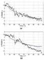
도 6a 및 6b는 본 발명의 특정 구체예에 따른 동역학적으로 변동하는 주파수 영역의 대표적인 예를 나타내는 도면들;
도 6c는 본 발명의 특정 구체예에 따른 동역학적으로 변하는 대역 통과 필터(BPF)를 나타내는 도면;
도 7은 본 발명의 특정 구체예에 따라서, 신호 및 이의 일차 도함수의 단일 박동의 전형적인 형태를 시간의 함수로 나타낸 개략도;
도 8은 본 발명의 특정 구체예에 따라서 제작된 프로토타입 시스템을 나타낸 개략도;
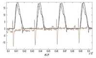
도 9a는 ECG 신호(흑색)와 동기화된, 쌈지 봉합법으로 고정된 3-Fr 마이크로마노미터에 의해 유도되었을 때, 좌심실 부피 신호를 ml의 단위로 (청색) 시간의 함수로서 나타내는 도면;
도 9b는 ECG 신호(흑색)와 동기화된, 본 발명의 특정 구체예에 따라서 수득한 신호 SCT(t)(적색)를 나타내는 도면;
도 10은 상행 대동맥 주위의 초음파 유동 탐침자에 의해 유도될 때의 좌심실 유동 신호(청색), 및 본 발명의 특정 구체예에 따라서 얻은 dSCT(t) 신호(흑색)를 나타내는 도면;
도 11은 도부타민을 주입하는 동안, 대동맥 초음파 유동 탐침자에 의해 유도된 평균 심박출량(청색), 및 본 발명의 특정 구체예에 따라서 얻은 dSCT(t) 신호에 의해 유도된 평균 심박출량(적색)을 나타내는 도면;
도 12a는 도부타민을 주입한 후, 대동맥 초음파 유동 탐침자에 의해 유도된 평균 심박출량(청색) 및 본 발명의 특정 구체예에 따라서 얻은 dSCL(t) 신호에 의해 유도된 평균 심박출량(흑색)을 나타내는 도면;
도 12b는 동맥 초음파 유동 탐침자에 의해 유도된 평균 심박출량(청색)과, 본 발명의 구체예에 따라서 수득한 dSCR(t) 신호에 의해 유도된 평균 심박출량(흑색)을, 심장 박동 수의 함수로서, 나타내는 도면;
도 13a는 심각한 부종의 진행 동안, 대동맥 초음파 유동 탐침자에 의해 유도된 평균 삼박축량(청색), 및 본 발명의 특정 구체예에 따라서 얻은 dSCR(t) 신호에 의해 유도된 평균 심박출량(흑색)을 나타내는 도면;
도 13b은 대동맥 초음파 유동 탐침자에 의해 유도된 평균 심박출량(청색), 및 본 발명의 특정 구체예에 따라서 얻은 dSCL(t) 신호에 의해 유도된 평균 심박출량(흑색)을 나타내는 도면; 및
도 14는 500cc 유체 볼러스를 조입하는 동안, 대동맥 초음파 유동 탐침자에 의해 유도된 평균 심박출량(청색), 및 본 발명의 특정 구체예에 따라서 얻은 dSPT(t) 신호에 의해 유도된 평균 심박출량(흑색)을 나타내는 도면.1 is a schematic block diagram showing a system according to a specific embodiment of the invention, suitable for monitoring hemodynamics;
2 is a schematic block diagram illustrating the system according to another embodiment of the present invention;
3 is a schematic block diagram illustrating a system according to certain embodiments of the present invention, which is a combination of the system shown in FIG. 1 and the system shown in FIG. 2;
4 is a schematic illustration of the principle of implementation of demodulation according to a specific embodiment of the system invention;
5A and 5B are schematic block diagrams of a demodulation system (FIG. 5A) and a processing system (FIG. 5B) according to certain embodiments of the present invention;
6A and 6B are diagrams showing representative examples of a dynamically varying frequency domain according to a specific embodiment of the present invention;
6C is a diagram illustrating a dynamically variable band pass filter (BPF) according to certain embodiments of the present invention;
7 is a schematic diagram showing a typical form of a single beat of a signal and its first derivative as a function of time, in accordance with certain embodiments of the invention;
8 is a schematic diagram showing a prototype system fabricated in accordance with certain embodiments of the present invention;
FIG. 9A is a plot showing the left ventricular volume signal as a function of time (blue) in units of ml when induced by a 3-Fr micromanometer fixed with a ssamzie suture, synchronized with an ECG signal (black);
9B is a diagram showing a signal SCT (t) (red) obtained according to a specific embodiment of the present invention, synchronized with an ECG signal (black);
Fig. 10 is a diagram showing a left ventricular flow signal (blue) as guided by an ultrasonic flow probe around the ascending aorta, and a dSCT (t) signal (black) obtained according to a specific embodiment of the present invention;
11 shows the average cardiac output induced by the aortic ultrasound flow probe (blue) during dobutamine injection, and the average cardiac output induced by the dSCT (t) signal obtained according to a specific embodiment of the present invention ( Red);
12A shows the average cardiac output induced by the aortic ultrasound flow probe (blue) after dobutamine injection and the average cardiac output induced by the dSCL (t) signal obtained according to a specific embodiment of the present invention (black );
12B shows the average cardiac output (blue) induced by the arterial ultrasound flow probe, and the average cardiac output (black) induced by the dSCR (t) signal obtained according to an embodiment of the present invention, and the number of heart beats. As a function of, the figure shown;
13A is an average cardiac output induced by the aortic ultrasound flow probe (blue), and the dSCR (t) signal obtained according to a specific embodiment of the present invention during the course of severe edema (black );
13B is a diagram showing the average cardiac output induced by the aortic ultrasound flow probe (blue), and the average cardiac output induced by the dSCL (t) signal obtained according to a specific embodiment of the present invention (black); And
FIG. 14 shows the average cardiac output (blue) induced by the aortic ultrasound flow probe during incorporation of the 500 cc fluid bolus, and the average induced by the dSPT (t) signal obtained according to a specific embodiment of the present invention. Diagram showing cardiac output (black).
발명의 특정 구체예의 설명Description of specific embodiments of the invention
본 발명은, 이의 특정 구체예에서, 의학 분야에 관한 것으로, 더욱 상세하게는, 그러나 배타적이지는 않게, 혈류 역학 감시 방법 및 시스템에 관한 것이다.The present invention, in certain embodiments thereof, relates to the field of medicine, and more particularly, but not exclusively, to methods and systems for monitoring hemodynamics.
본 발명의 적어도 하나의 구체예를 상세히 설명하기 전에, 본 발명은 하기 설명에서 설정된 및/또는 도면 및/또는 실시예에 예증된 구성의 상세점 및 성분 및/또는 방법의 배열에 그 적용이 필수적으로 제한되지 않는다는 것이 이해되어야 한다. 본 발명은 다른 구체예를 가능하게 하거나 다양한 방식으로 실행 또는 수행될 수 있다.Before describing at least one embodiment of the present invention in detail, the present invention is essential to its application to the details of the construction and arrangement of components and/or methods set forth in the following description and/or illustrated in the drawings and/or examples. It should be understood that it is not limited to. The present invention enables other embodiments or can be implemented or carried out in a variety of ways.
본 발명자들은 신호의 분해 성분들을 사용하여 대상체의 혈류 역학적 상태를 평가할 수 있고, 여기서, 상이한 성분들이 이들이 가지는 정보의 관점에서 서로 보충적이라는 것을 관찰하였다. 본 발명자들은 맥관구조물의 동일한 지역의 다른 부분으로부터 얻는 신호들이 서로 보충적이라는 것을 또한 관찰하였다. 본 발명자들은 대상자의 혈류역학을 감시할 목적으로, 상기 관측들 중 하나 또는 둘 다를 이용하는 기술을 고안하였다.The inventors have observed that the decomposition components of the signal can be used to evaluate the hemodynamic state of a subject, where different components are complementary to each other in terms of the information they have. The inventors have also observed that signals from different parts of the same area of the vasculature are complementary to each other. The present inventors devised a technique using one or both of the above observations for the purpose of monitoring the subject's hemodynamics.
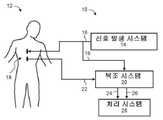
도면을 참조하면, 도 1은 대상자(12)의 혈류역학을 감시하기에 적합한, 본 발명의 특정 구체예에 따른 시스템(10)을 나타내는 개략적인 블록도이다. 시스템(10)은 일반적으로, 바람직하게는 하나 이상의 출력 전기 신호(16)를 제공하며 및 신호(16)를 상기 대상자(12)의 기관(18)에 전달하는 신호 발생 시스템(14)을 포함한다. 신호(들)(16)는 당해 분야에 공지된 것과 같이 의학적 리드선을 통해 전달될 수 있다.Referring to the drawings, FIG. 1 is a schematic block diagram illustrating a
명확한 표현을 위해, 의학적 리드선은 이들이 가지는 신호들의 참조 신호에 의해 지정된다.For clarity, medical leads are designated by the reference signal of the signals they have.
기관(18)은 인간 또는 동물의 신체의 임의의 부분일 수 있다. 바람직하게는, 기관(18)은 외부 기관이어서 신호의 전달이 비침습적으로 이루어질 수 있다. 기관(18)의 대표적인 예는, 제한 없이, 가슴, 엉덩이, 대퇴부, 목, 머리, 팔, 전완, 복부, 등, 둔근, 다리, 및 발을 포함한다. 본 발명의 특정 구체예에서 기관(18)은 가슴이다.
본 발명의 특정 구체예에서 시스템(10)은 출력 신호(16)에 반응적으로 기관(18)로부터 감지된 입력 전기 신호(22)를 수신하도록 및 출력 신호(16)를 이용하여 입력 신호(22)를 변조하여 입력 신호(22)의 동상분(24) 및 직각 성분(26)을 제공하도록 구성된 복조 시스템(20)을 포함한다. 시스템(10)은, 특정 구체예에 있어서, 동상분(24) 및 직각 성분(26)에 기반하여 혈류역학을 감시하도록 구성된 처리 시스템(28)을 더 포함한다.In certain embodiments of the present invention, the
도 2는 본 발명의 다른 구체예에 따른 시스템(10)을 나타내는 개략적인 블록도이다. 도 2에 나타난 구체예에서, 신호 발생 시스템(14)은 제1 출력 전기 신호(32) 및 제2 출력 전기 신호(34)로 지칭되는 2개 신호를 제공하고, 및 이들을 기관(18)으로 전달한다. 예를 들어, 신호(32)는 기관(18)의 좌측으로 전달될 수 있고 신호(34)는 기관(18)의 우측으로 전달될 수 있다. 본 발명의 특정 구체예에서, 신호(32, 34)는 의존성 신호이다. 대안적으로, 신호(32, 34)는 독립적 신호일 수 있다.2 is a schematic block diagram illustrating a
본 발명에서 사용되는 바와 같이, "의존성 신호들"이란 그것들의 주파수, 위상 및 진폭 중 적어도 하나, 더욱 바람직하게는 적어도 2개, 더욱 바람직하게는 임의의 것에서 동기화된 신호들을 의미한다.As used in the present invention, "dependent signals" mean signals synchronized in at least one, more preferably at least two, more preferably any of their frequency, phase and amplitude.
본 발명에서 사용된 바와 같이, "독립적 신호들"이란 그것들의 주파수, 위상 및 진폭 중 적어도 하나, 더욱 바람직하게는 적어도 2개, 더욱 바람직하게는 임의의 것에서 동기화되지 않은 신호들을 의미한다.As used herein, "independent signals" mean signals that are not synchronized in at least one, more preferably at least two, more preferably any of their frequency, phase and amplitude.
신호 발생 시스템(14)이 2개보다 많은 (의존성 또는 독립적) 신호들을 제공하는 구체예가 또한 고려된다.Embodiments are also contemplated in which the
도 2에 설명된 구체예에서, 처리 시스템(28)은 제1 출력 신호(32)에 반응적으로, 기관(18)의 제1 부분(상기 예에서 우측)으로부터 감지된 제1 입력 전기 신호(36), 및 제2 출력 신호(34)에 반응적으로, 기관(18)의 제2부분(상기 예에서 좌측)으로부터 감지된 제2 입력 전기 신호(38)을 수신한다. 처리 시스템(28)은 바람직하게는 입력 신호(36, 38)에 기반하여 상기 혈류역학을 감시한다.In the embodiment illustrated in FIG. 2, the
본 발명의 다양한 예증적 구체예에서, 도 1에 도시된 구체예는 도 2에 설명된 구체예와 조합된다. 그러한 조합의 대표적인 예가 도 3에 설명되어 있다. 본 구체예에서, 신호 발생 시스템(14)은 2개 이상의 출력 신호들, 그러나 필수적으로 독립적인 신호는 아닌 신호를 제공하고, 이를 기관(18)의 개별 부분으로 전달한다. 제한적으로 간주되지 않는 도 3의 개략적 예시에 있어서, 발생 시스템(14)은 2개 신호(32, 34)를 제공하고, 이들을 각각 기관(18)의 우측 및 좌측으로 전달한다.In various illustrative embodiments of the invention, the embodiment shown in FIG. 1 is combined with the embodiment described in FIG. 2. A representative example of such a combination is described in FIG. 3. In this embodiment, the
본 발명의 특정 구체예에서 복조 시스템(20)은 상기 각각의 출력 신호에 반응적으로, 기관(18)의 각 부분으로부터 감지된 입력 전기 신호를 수신한다. 예를 들어, 복조 시스템(20)은 제1 출력 신호(32)에 반응적으로, 기관(18)의 제1 부분으로부터 감지된 제1 입력 신호(36), 및 제2 출력 신호(34)에 반응적으로 기관(18)의 제2 부분으로부터 감지된 제2 입력 신호(38)를 수신할 수 있다. 복조 시스템(20)은 조건적으로 및 바람직하게는, 상기 입력신호들을 사용하여 모든 입력신호들을 변조하여, 각 입력 신호에 대하여, 동상분 및 직각 성분을 제공한다. 따라서, 복조 시스템(20)은 바람직하게는 2N 신호들을 제공하고, 여기서, N은 상기 수신된 입력 신호들의 수이다.In certain embodiments of the invention the
복조 시스템(20)이 입력 신호(36, 38)를 수신하는 상기 예에서, 시스템(20)의 출력은 둘 다가 제1 입력 신호(36)의 복조인, 제1 동상분(40)과 제1 직각 성분(42), 및 둘 다가 제2 입력 신호(38)의 복조인 제2 동상분(44) 및 제2 직각 성분이다.In the above example in which the
전술한 바와 같은 및 본 발명의 특정 구체예에 따른 시스템(10)의 상세한 설명이 제공될 것이다.A detailed description of the
발생 시스템(14)에 의해 제공되는 신호들은 바람직하게는 교류(AC) 신호이고 임의의 주파수일 수 있다. 라디오주파수 신호들이 유용하다고 본 발명자들에게 발견되었지만, 본 발명의 범위를 임의의 특정 주파수에 제한하고자 하는 의도가 아니다. 특히, 전달된 신호들의 주파수는 상기 라디오주파수 범위 아래, 상기 라디오주파수 범위 내, 또는 상기 라디오주파수 범위 위일 수 있다. 본 구체예에 적합한 대표적인 주파수 범위는, 제한됨 없이, 20KHz 내지 800KHz, 예, 약 75KHz를 포함한다. 본 구체예의 신호 발생 시스템에 의해 발생된 신호는 기관 전체에 흐르고, 신체의 임피던스로 인하여 전압 강하를 야기한다. 상기 입력 라디오주파수 신호들은, 일반적으로, 그러나, 필수적인 것은 아닌, 대상자의 기관의 임피던스와 관련이 있다. 본 발명의 다양한 예증적 구체예에서, 상기 출력 신호(들)의 상기 매개변수 (예, 주파수, 진폭, 위상)을 선택하여 상기 입력 신호가 기관(18)의 임피던스를 나타내도록 한다. 신호의 전형적인 피크 대 피크 진폭은 600mv 아래이고, 이에 제한되지 않는다.The signals provided by the
일반성을 잃지 않고, 상기 입력 신호들은 하기에 "임피던스"로 지칭되나, 임피던스에 대하여 더 상세하게 참조하는 것은 여하한 본 발명의 범위를 제한하는 것으로서 해석되지 않아야 하고, 및 상기 신호는 제한없이, 전압, 전류, 저항, 리액턴스를 포함하는 다른 측정가능한 전기적 양으로서 표시되어야 한다는 것이 이해될 것이다.Without losing generality, the input signals are hereinafter referred to as “impedance”, but further reference to impedance should not be construed as limiting the scope of any invention, and the signal is, without limitation, voltage It will be understood that it should be expressed as other measurable electrical quantities including current, resistance, and reactance.
임피던스 신호가 하기 식 중 임의의 것을 만족시키는 복소수로서 표시될 수 있다:The impedance signal can be expressed as a complex number that satisfies any of the following equations:
ZP = |Z| exp(jxφZ)(식 1)ZP= |Z| exp(jxφZ) (Equation 1)
및And
ZC =Zr + jZi(식 2).ZC=Zr+ jZi (Equation 2).
상기식에서,ZP는 극 표시를 나타내고 및ZC는 데카르트 표시를 나타내며, |Z|는 임피던스의 절대 진폭이고,φZ는 임피던스의 위상이고, Zr 은 임피던스의 실수 성분이고, Zi 는 임피던스의 허수 성분이고, 및j 는j2 = -1을 만족하는 순수 허수이다.In the above formula,ZP denotes the polar mark andZC denotes the Cartesian mark, |Z| is the absolute amplitude of the impedance,φZ is the phase of the impedance, Zr is the real component of the impedance, and Zi is the impedance Is the imaginary component of, andj is a pure imaginary number satisfyingj2 = -1.
성분들 (|Z|,φZ) 및 (Zr,Zi) 간의 관계는 다음과 같다:The relationship between the components (|Z|,φZ ) and (Zr, Zi ) is as follows:
Zr = |Z|Cos(φZ); Zr = |Z|Sin(φZ).(식 3)Zr = |Z|Cos(φZ ); Zr = |Z|Sin(φZ ). (Equation 3)
및And
|Z|= sqrt(Zr2 + Zi2);φZ = arctan(Zi/ Zr)(식 4)|Z|= sqrt(Zr2 + Zi2 );φZ = arctan(Zi / Zr ) (Equation 4)
상기 극 성분 |Z| 및φZ는, 예를 들어, 상기 WO2010032252에서 개시된 바와 같이, 진폭 변조(AM) 포락선 검출기, 및 위상 변조(PM) 검출기를 각각 사용하여 검출될 수 있다.The polar component |Z| AndφZ can be detected using an amplitude modulation (AM) envelope detector and a phase modulation (PM) detector, respectively, as disclosed in, for example, WO2010032252 above.
수신된 임의의 입력 신호들에 대하여 바람직하게는 복조 시스템(20)에 의해 수행되는 직각 복조를 사용하여 상기 신호로부터 데카르트 성분들을 직접적으로 추출하는 것이 유리하다는 것을 본 발명자들은 발견하였다. 복조 시스템(20)의 바람직한 실행 원리는 도 4에서 개략적으로 설명되어 있다.The inventors have found that it is advantageous to extract Cartesian components directly from the signal on any input signals received, preferably using a quadrature demodulation performed by the
여기서 설명된 임의의 신호 조작에서, 신호 및 그 성분들은 시간의 함수로 변동한다는 것으로 이해되어야 한다.It should be understood that in any signal manipulation described herein, the signal and its components fluctuate as a function of time.
수신된 입력 신호R은 (i) 전달된 출력 신호와 동상(in-phase)인 신호 A, 및 (ii) 상응하는 전달된 출력 신호 T에 비하여, 통상 위상 천이기(404)를 사용하여 위상 천이된 신호 B에 의해 병렬적으로 다중화된다. 이러한 과정은 2개의 다중화 신호 RxA 및 RxB를 각각 제공한다. 상기 다중화 신호는 신호 배율기(multiplier) MA 및 MB를 사용하여 얻을 수 있다. 다음, 상기 다중화 신호 RxA 및 RxB를 저역 필터(402)를 사용하여 필터한다. 본 발명의 특정 구체예에서 다중화 신호 RxA 및 RxB는 또한 고역 필터를 사용하여 필터한다. 이것은, 예를 들어, 필터(402) 직전 또는 직후에 고역 필터를 추가함으로써, 또는 필터(402)를 대역 통과 필터로 만듦으로써 성취될 수 있다.The received input signalR is compared to (i) a signal A that is in-phase with the transmitted output signal, and (ii) the corresponding transmitted output signal T, using a conventional phase shifter 404 to phase shift. Is multiplexed in parallel by signal B. This process provides two multiplexed signals RxA and RxB, respectively. The multiplexed signal can be obtained using signal multipliers MA and MB. Next, the multiplexed signals RxA and RxB are filtered using a
상기 저역 필터에 대한 통상적인 컷오프 주파수는, 제한없이, 약 5 Hz 내지 약 20 Hz이거나, 또는 약 5 Hz 내지 약 15 Hz, 또는 약 8 Hz 내지 약 12 Hz, 예, 약 9 Hz 이하의 컷오프 주파수이다. 고역 필터 LPF에 대한 통상적인 컷오프 주파수는, 제한없이, 약 0.5 Hz 내지 약 1.5 Hz이거나, 약 0.6 Hz 내지 약 1.4 Hz 또는 약 0.7 Hz 내지 약 1.3 Hz, 예, 0.8 Hz의 컷오프 주파수이다. 본 발명의 다양한 예증적 구체예에서, 상기 다중화 신호 R?A 및 R?B는, 후술하는 바와 같이, 역동적 적응(adaptive) 필터에 의해 필터된다. 상기 역동적 적응 필터는 필터(402) 중 하나 또는 둘 다에 추가될 수 있다. 대안적으로 필터(402) 중 하나 또는 둘 다는 상기 역동적 필터에 의해 대체될 수 있다.Typical cutoff frequencies for the low pass filter are, without limitation, from about 5 Hz to about 20 Hz, or from about 5 Hz to about 15 Hz, or from about 8 Hz to about 12 Hz, e.g., a cutoff frequency of about 9 Hz or less. to be. A typical cutoff frequency for a high pass filter LPF is, without limitation, from about 0.5 Hz to about 1.5 Hz, from about 0.6 Hz to about 1.4 Hz, or from about 0.7 Hz to about 1.3 Hz, such as 0.8 Hz. In various illustrative embodiments of the present invention, the multiplexed signals R?A and R?B are filtered by a dynamic adaptive filter, as described below. The dynamic adaptive filter may be added to one or both of the
RxA로부터 얻은 필터된 신호는 입력 신호 R의 동상분 I로 지칭되고, RxB로부터 얻은 필터된 신호는 입력 신호 R의 직각성분 Q로 지칭된다.The filtered signal obtained from RxA is referred to as the in-phase component I of the input signal R, and the filtered signal obtained from RxB is referred to as the quadrature component Q of the input signal R.
통상적으로, 상기 위상 천이기는 π/2의 상 천이를 발생시키고, 그래서 B는 T에 대하여 π/2 천이된다. 그러나, 이것은 필수적으로 필요한 경우가 아닌 데, 본 발명의 특정 구체예에서, 위상 천이는 π/2외 다른 위상 천이를 발생시키기 때문이다.Typically, the phase shifter produces a phase shift of π/2, so B is π/2 shifted with respect to T. However, this is not necessarily the case, since, in certain embodiments of the present invention, the phase shift causes a phase shift other than π/2.
따라서, 본 발명에서 사용되는 바, "직각 성분"은 수신된 입력 신호 R과 신호 B 사이의 저역 필터된 다중화의 결과인 것으로서, 상응하는 출력 신호 T에 대하여 위상 천이되며, T에 대한 B의 위상천이(Δφ)인, 임의의 신호를 지칭한다.Thus, as used in the present invention, the "rectangular component" is a result of low-pass filtered multiplexing between the received input signal R and signal B, and is phase shifted with respect to the corresponding output signal T, and the phase of B with respect to T Refers to any signal, which is a transition (Δφ ).
본 발명의 특정 구체예에서 Δφ는 약 π/2이다.In certain embodiments of the invention Δφ is about π/2.
시스템(20)에 의해 수행되는 복조는 직각 복조를 수행할 수 있는 임의의 공지된 회로도를 사용하여 수행될 수 있다. 상기 회로도는 필요시, 디지털 또는 아날로그일 수 있다. 본 발명의 특정 구체예에서, 상기 회로도는 아날로그이다. 적절한 아날로그 회로도는 카탈로그 번호 AD8333, Analog Devices Analog Devices, Inc., Norwood, MA 제품이다.The demodulation performed by the
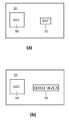
본 발명의 특정 구체예에서, 복조 시스템(20)은 디지털 방식으로 처리를 수행한다. 이러한 구체예에서, 복조 시스템(20)은 아날로그에서 디지털 컨버터 및 디지털 데이터 처리기 또는/및 디지털 신호 처리기 또는/및 필드 프로그램가능 게이트 어레이를 포함한다. 아날로그에서 디지털 컨버터(ADC)(50) 및 디지털 신호 처리기(DSP)(52)를 가지는 시스템(20)의 대표적인 예가 도 5a에 설명되어 있다. 아날로그 신호들은 ADC(50)에 의해 수신되고, 미리 정해진 샘플링 속도에 따라 디지털화되고, 구분된 데이터의 벡터로서 데이터 DSP(52)로 전달된다. 통상적인 샘플 속도는, 제한없이, 약 200 KHz 내지 약 1.5 MHz이다. DSP(52)는 입력 신호R 및 전달된 신호T를 수신하고, 및 디지털적으로 수행하는 것을 제외하고는 전술한 바와 같이, I 및 Q 신호를 계산한다. 따라서, 도 4를 참조하면, 복조 시스템(20)은 디지털 방식으로, 처리를 수행하고, 위상 천이기(404), 신호 배율기 MA 및 MB, 및 필터(402)는 각각 독립적으로 디지털 요소일 수 있다.In certain embodiments of the present invention,
처리 시스템(28)은 입력 신호에 의해 운반된 모니터링 정보를 제공하는 역할을 한다. 처리 시스템(28)은 시스템(20)으로부터 (도 1 및 3) 또는 직접 기관으로부터 (도 2) 신호를 수신하고, 그 신호들을 처리하고, 및 처리된 신호와 관계하는 출력을 발생시킨다. 바람직하게, 상기 출력은 도식적 출력이고 이는 디스플레이 카드, 컴퓨터의 네트워크 카드나 메모리 매체와 같은 컴퓨터 판독가능 매체로 전달된다. 상기 컴퓨터 판독가능 네트워크 카드로부터, 상기 출력은 국소 또는 원격 컴퓨터에 의해 판독되고, 예를 들어, 디스플레이 장비 상에 디스플레이 될 수 있다.The
조건적으로 및 바람직하게, 처리 시스템(28)은 상기 처리를 디지털 방식으로 수행한다. 이러한 구체예에서, 처리 시스템(28)은 아날로그에서 디지털 컨버터 및 디지털 데이터 처리기나 디지털 신호 처리기를 포함할 수 있다. 복조 시스템(20)이 디지털일 때, 처리 시스템(28)이 아날로그에서 디지털 컨버터를 포함할 필요가 없는 데, 이러한 구체예에서, 처리 시스템(28)은 디지털 신호를 복조 시스템(20)으로 부터 수신하기 때문이다.Conditionally and preferably, the
아날로그에서 디지털 컨버터(ADC)(54) 및 데이터 처리기(56)를 가지는 시스템(28)의 대표적인 예가 도 5b에 나타나 있다. 이러한 구체예는 복조 시스템(20)의 출력(예, 필터(402) 후)이 아날로그 신호를 포함할 때 유용하다. 상기 아날로그 신호들은 ADC(54)에 의해 수신되고, 미리 정해진 샘플링 속도에 따라 디지털화되고, 및 구분된 데이터의 벡터로서 데이터 처리기(56)에 전달된다. 통상적인 샘플 속도는, 제한 없이, 약 200 Hz 내지 약 800 Hz이다.A representative example of a
데이터 처리기(56)은 범용 컴퓨터 또는 전속 회로도일 수 있다. 본 구체예의 처리 기술을 수행하는 컴퓨터 프로그램은, 이에 제한되지 않는, 플로피 디스크, CD-ROM 또는 플래시 메모리와 같은 분배 매체 상에서 사용자들에게 공통적으로 분배될 수 있다. 상기 분배 매체로부터, 상기 컴퓨터 프로그램은 하드 디스크로 또는 유사 중간 저장 매체로 복사될 수 있다. 대안적으로, 컴퓨터 프로그램은 예를 들어, http 또는 ftp 인터넷 사이트로부터 다운로드될 수 있는 데이터 스트림으로서 분배될 수 있고, 이 경우, 컴퓨터 프로그램은 상기 인터넷 사이트로부터 직접 컴퓨터로 복사될 수 있다. 상기 컴퓨터 프로그램은 분배 매체나 중간 저장 매체로부터 컴퓨터의 실행 메모리로 컴퓨터 명령을 로딩하고, 그 컴퓨터를 본 발명의 방법에 따라서 작동하도록 구성함으로써 실행될 수 있다. 모든 이러한 조작은 컴퓨터 시스템의 분야의 숙련자에게 공지되어 있다.The
처리 시스템(28)은 한 가지 방법 이상으로 혈류역학 감시할 수 있다.
특정 구체예에서, 시스템(28)은 시스템(20)에 의해 수신되는 바와 같이, 각 신호에 기반하여, 개별 출력을 발생시킨다. 상기 출력은 신호 자체의 도식적 표시(예, 시간의 함수로서), 또는 신호들의 시간 도함수(예, 일차 시간 도함수(time-derivative) 또는 곡선하 면적을 포함할 수 있다. 조건적으로 및 바람직하게, 시스템(28)은, 상기 출력을 발생하기 전에, 표준화 과정을 수행하여, 예를 들어, 상이한 출력 유형에 대하여 유사한 척도를 얻는다.In certain embodiments,
특정 구체예에서, 시스템(28)은 시스템(20)에 의해 수신되는 바와 같이, 신호들의 조합에 기반하여 출력을 발생시킨다. 그러한 조합물들의 대표적인 예가 하기에 제공된다. 하나 이상의 조합이 시스템(28)에 의해 계산될 때, 개별 출력은 각 신호 조합에 대하여 조건적으로 제공될 수 있다.In certain embodiments,
본 발명의 특정 구체예에서 시스템(28)은 신호를 디스플레이 하기 전, 역동적 적응 필터를 그 신호에 적용한다. 이러한 필터화는 바람직하게는 대상자의 생리적 조건에 반응적으로 수행된다. 필터화는, 예를 들어, 참조함으로써 그 내용이 본 발명에 편입되는 국제 특허 공개 번호 2009/022330에 개시된 필터링 기술을 위상 및 절대 성분에 분리적으로 사용함으로써, 수행될 수 있다.In certain embodiments of the present invention,
일반적으로, 상기 역동적 가변 필터는 상기 대상자의 생리적 조건의 변화에 반응하여 역동적으로 적응된 주파수 대역에 따라 데이터를 필터한다. 주파수 대역을 대상자의 생리적 조건에 역동적으로 적응시키는 것은 무관한 신호의 측정된 특성에 대한 영향을 유의하게 감소시킬 수 있다는 것을 본 발명자들은 발견하였다.In general, the dynamically variable filter filters data according to a dynamically adapted frequency band in response to a change in a physiological condition of the subject. The inventors have found that dynamically adapting the frequency band to the subject's physiological conditions can significantly reduce the influence of the irrelevant signal on the measured properties.
따라서, 본 구체예에서, 시스템(28)은 먼저 대상자의 생리적 조건이 결정되고, 다음 주파수 대역이 대상자의 생리적 조건에 기반하여 선택된 후 수신된 신호를 주파수 대역에 따라 필터되는 과정을 사용한다. 상기 주파수 대역은 생리적 조건에서의 변화에 반응하여 역동적으로 적응된다.Thus, in this embodiment, the
상기 생리적 조건은, 바람직하게는, 그러나 필수적인 것은 아닌, 대상자의 심박수이다. 생리적 조건에 관한 데이터는, 필요시, 아날로그나 디지털 형태로, 적절한 데이터 수집 단위체를 통해 수집될 수 있다. 예를 들어, 생리적 조건은 예를 들어, ECG 신호 등의 분석에 의해, 결정될 수 있는 심박수일 수 있다.The physiological condition is, preferably, but not necessarily, the subject's heart rate. Data on physiological conditions may be collected through an appropriate data collection unit, in analog or digital form, if necessary. For example, the physiological condition may be a heart rate that can be determined, for example, by analysis of an ECG signal or the like.
하기 구체예들이 심박수인 생리적 조건에 특별한 강조점을 가지고 설명하지만, 심박수에 대하여 더 상세하게 참조하는 것은 여하간 본 발명의 범위를 제한하는 것으로 해석되어서는 안되는 것으로 이해되어야 한다. 예를 들어, 본 발명의 예증적 구체예에서, 생리적 조건은 대상자의 호흡량, 특정 근육 단위체의 반복율 및/또는 활동전위 감지된 근전도검사의 하나 이상의 특성이다.Although the following embodiments are described with particular emphasis on the physiological condition of heart rate, it should be understood that any reference to heart rate in more detail should not be construed as limiting the scope of the invention in any way. For example, in an illustrative embodiment of the invention, the physiological condition is one or more characteristics of the subject's respiration volume, the repetition rate of a particular muscle unit, and/or action potential detected EMG.
주파수 대역을 생리적 조건에 적응시키는 것은 당해 분야에 공지된 임의의 적응 계획에 따라 실행될 수 있다. 예를 들어, 주사수 대역의 하나 이상의 매개 변수들(예, 하한, 상한, 대역폭, 중앙 주파수)은 상기 생리적 조건을 특징 짓는 매개 변수의 선형 함수이다. 그러한 매개 변수는, 예를 들어, 분당 심박수일 수 있다.Adapting the frequency band to physiological conditions can be carried out according to any adaptation scheme known in the art. For example, one or more parameters of the scan number band (eg, lower limit, upper limit, bandwidth, center frequency) are a linear function of the parameter characterizing the physiological condition. Such a parameter may be, for example, heart rate per minute.
도 6a 및 도 6b는 역동적으로 가변되는 주파수 대역의 대표적인 예를 나타내고, 이는, 후술하는 바와 같이, 본 발명의 특정 구체예에 따라서 시스템(28)에 의해 수신된 각 신호에 개별적으로 및/또는 신호들의 임의의 조합에 집단적으로 사용될 수 있다.6A and 6B show representative examples of dynamically varying frequency bands, which are individually and/or signaled to each signal received by the
도 6a 및 도 6b에 대상자의 심박수에 대한 주파수 대역(도 6a에서 상한 및 도 6b에서 하한)의 함수적 의존성이 나타난다. 도 6a에 나타난 바와 같이, 주파수 대역의 상한은 선형적으로 변화하여 분당 약 60번의 맥박수(bpm)에서, 상기 상한은 약 6 Hz이고, 약 180 bpm의 맥박수에서, 상한은 약 9 Hz이다. 도 6b에 나타난 바와 같이, 주파수 대역의 하한은 선형적으로 변화하여 약 60의 맥박수에서 하한은 약 0.9 Hz bpm이고, 약 180 bpm의 맥박수에서, 하한은 약 2.7 Hz이다.6A and 6B show the functional dependence of the frequency band (the upper limit in FIG. 6A and the lower limit in FIG. 6B) on the subject's heart rate. As shown in Fig. 6A, the upper limit of the frequency band is linearly changed so that at a pulse rate of about 60 times per minute (bpm), the upper limit is about 6 Hz, and at a pulse rate of about 180 bpm, the upper limit is about 9 Hz. As shown in FIG. 6B, the lower limit of the frequency band changes linearly, so that at a pulse rate of about 60, the lower limit is about 0.9 Hz bpm, and at a pulse rate of about 180 bpm, the lower limit is about 2.7 Hz.
본 발명의 특정 구체예에서, 상한은 대략 함수 FU(HR)과 동등하고 이는 FU(HR) = 6 + 1.5 x [(HR/60) - 1]Hz으로 정의되며, 상기 식에서 HR은 bpm 단위인 상기 대상자의 맥박수이다. 특정 구체예에서, 상한은 모든 시간에서 FU(HR)과 동일하고, 다른 구체예에서, 상한은 반복 과정을 사용하여 설정된다.In certain embodiments of the invention, the upper limit is approximately equal to the function FU (HR), which is defined as FU (HR) = 6 + 1.5 x [(HR/60)-1] Hz, where HR is bpm The unit is the subject's pulse rate. In certain embodiments, the upper limit is equal to FU (HR) at all times, and in other embodiments, the upper limit is set using an iterative process.
본 발명의 특정 구체예에서, 하한은 대략 함수 FL(HR)와 동일하고 이는 FL(HR) = 0.9 x (HR/60)Hz로 정의된다. 특정 구체예에서, 하한은 모든 시간에서 FL(HR)와 동일하고 다른 구체예에서, 하한은 반복 과정으로 설정된다.In certain embodiments of the invention, the lower limit is approximately equal to the function FL (HR), which is defined as FL (HR) = 0.9 x (HR/60) Hz. In certain embodiments, the lower limit is equal to FL (HR) at all times and in other embodiments, the lower limit is set as a repeating process.
본 발명의 특정 구체예에 적합한 반복 과정의 대표적인 예는 하기에 제공된다.Representative examples of iterative procedures suitable for certain embodiments of the present invention are provided below.
역동적으로 가변되는 주파수 상한 및 역동적으로 가변되는 주파수 하한에 의해 특징되는 역동적으로 가변되는 대역 통과 필터(BPF)는, 본 발명의 특정 구체예에 따라서 도 6c에 나타나 있다. 나타난 바와 같이, 각 심박수는 하한 및 상한에 의해 정의된 주파수 대역과 연관된다. 예를 들어, 60 bpm의 심박수의 경우, 도 6c는 하한이 약 0.9 Hz이고 상한이 약 6 Hz인 BPF를 나타낸다.A dynamically variable band pass filter (BPF), characterized by a dynamically variable upper frequency limit and a dynamically variable lower frequency limit, is shown in FIG. 6C according to a specific embodiment of the invention. As shown, each heart rate is associated with a frequency band defined by a lower and upper limit. For example, in the case of a heart rate of 60 bpm, FIG. 6C shows a BPF with a lower limit of about 0.9 Hz and an upper limit of about 6 Hz.
상기 제시된 값과 도 6a 내지 도 6c에 나타난 함수적 관계는 예증적 구체예이고 여하간 본 발명의 범위를 제한하는 것으로 간주되어서는 안되는 것으로 이해되어야 한다. 다른 예증적 구체예에서, 주파수 대역 및 생리적 조건 간의 함수적 관계는 상이한 기울기 및/또는 옵셋들을 가질 수 있거나, 그들은 비선형적일 수 있다.It is to be understood that the values presented above and the functional relationships shown in FIGS. 6A-6C are illustrative embodiments and should not be considered as limiting the scope of the invention in any way. In another illustrative embodiment, the functional relationship between the frequency band and physiological condition may have different slopes and/or offsets, or they may be non-linear.
하기에, 본 발명의 특정 구체예에 따른 절대 성분을 위상 성분으로 및 개별적으로 필터하는 대역 통과 필터의 주파수 대역을 결정하는 반복 과정이 설명된다. 상기 반복 과정은, 특정 구체예에서, 각각의 필터된 성분으로부터 추출되거나 계산될 때의 생리적 매개변수의 값 및 참조 신호, 예를 들어, ECG 신호로부터 추출되거나 계산될 때의 동일한 생리적 매개변수의 값과의 비교에 근거하고 있다.In the following, an iterative process of determining a frequency band of a band pass filter that filters an absolute component as a phase component and individually according to a specific embodiment of the present invention is described. The iterative process, in certain embodiments, is the value of the physiological parameter when extracted or calculated from each filtered component and the value of the same physiological parameter when extracted or calculated from a reference signal, e.g., an ECG signal. It is based on a comparison with
용어, "생리적 매개 변수"는 측정가능하거나 계산가능한 및 생리적 활성, 특별하지만 필수적이진 않는, 심장의 활성을 나타내는 임의의 가변적 매개변수를 지칭한다. 본 발명의 다양한 예증적 구체예에서, 상기 생리적 매개변수는 심박수 그 자체외 다른 것이다. 상기 생리적 매개 변수는 시간 연관 매개변수, 진폭 연관 매개변수 또는 이의 조합일 수 있다.The term “physiological parameter” refers to any variable parameter that is measurable or countable and that indicates physiological activity, special but not essential, activity of the heart. In various illustrative embodiments of the present invention, the physiological parameter is other than the heart rate itself. The physiological parameter may be a time-related parameter, an amplitude-related parameter, or a combination thereof.
일반적으로, 필터 신호 및 참조 신호는 시간의 함수로서 진폭으로 표시된다. 따라서, 시간 관련 매개변수들은 신호들의 횡좌표 값을 이용하여 통상 계산되고 및 진폭 관련 매개변수들은 신호의 종좌표를 사용하여 통상 계산된다.In general, filter signals and reference signals are expressed as amplitudes as a function of time. Thus, time-related parameters are usually calculated using the abscissa values of the signals and amplitude-related parameters are usually calculated using the ordinate of the signal.
본 발명에 적절한 시간 관련 생리적 변수들의 대표예는, 제한없이, 심장 수축기 시간, 심장 확장기 시간, 전박출(pre-ejection)기간, 및 박출기간을 포함한다. 본 발명에 적합한 진폭-연관 생리적 매개변수의 대표적인 예는, 제한 없이, 일회 맥박 동안 영(0) 위의 최대 진폭, 일회 맥박 동안 최대 피크-대-피크 진폭, 및 일회 맥박 동안 RMS 수준을 포함한다. 또한 고려되는 것은 상기 신호에 걸쳐 2개 지점간의 평균 기울기와 같은, 그러나 이에 한정되지 않는, 다양한 기울기 매개변수이다.Representative examples of time-related physiological variables suitable for the present invention include, without limitation, systolic time, diastolic time, pre-ejection period, and ejection period. Representative examples of amplitude-related physiological parameters suitable for the present invention include, without limitation, the maximum amplitude above zero for a single pulse, the maximum peak-to-peak amplitude during a single pulse, and the RMS level during the single pulse. . Also considered are various slope parameters, such as, but not limited to, the average slope between two points across the signal.
본 발명의 다양한 예증적 구체예에서, 상기 생리적 매개변수는 심실 분출 시간(VET)이다.In various illustrative embodiments of the invention, the physiological parameter is ventricular ejection time (VET).
하기 구체예가 VET에 대한 특별한 강조점을 가지고, 생리적 매개변수로서 설명되어 있지만, VET에 더 상세한 참조를 한다고 해도 이는 여하간 본 발명의 범위를 제한하는 것으로 해석되어서는 안되는 것으로 이해되어야 한다.While the following embodiments have particular emphasis on VET and are described as physiological parameters, it is to be understood that any more detailed reference to VET should not be construed as limiting the scope of the invention in any way.
본 발명자들은 특별한 대상자에 대한 상당한 양의 생물학적 정보를 FL(HR) 내지 5.5 Hz의 주파수 범위로부터 얻을 수 있고, 여기서 HR은 대상자의 심박수이다. 특정 의학적 조건에 대하여, 상기 정보의 일부는 5.5 Hz과 FU(HR) 사이에 있을 수 있다는 것을 본 발명자들이 또한 발견하였다.We can obtain a significant amount of biological information for a particular subject from the frequency range of FL (HR) to 5.5 Hz, where HR is the subject's heart rate. For certain medical conditions, the inventors have also found that some of the information may be between 5.5 Hz and FU (HR).
동일한 생리적 매개변수를 추출하거나 계산하는 2개의 상이한 기술 간의 비교의 장점은 상기 대역 통과 필터의 주파수 상한을 실질적으로 최적화하게 한다는 것이다. 본 발명의 다양한 예증적 구체예에서, 상기 반복 과정의 각 반복의 경우, 비교가 반복된다. 상기 비교가 소정의 기준을 만날 때, 상기 주파수 상한은 상기 상한에 대한 낮은 역치 및 상기 상한에 대한 높은 역치 간의 평균을 계산함으로써 업테이트된다. 상기 주파수 하한은 일정 한계(예, 약 0.9 Hz 내지 약 2.7 Hz인 일정 주파수)일 수 있거나 역동적, 예를 들어, FL(HR), 여기서 HR은 각각의 반복 전 또는 그 동안의 대상자의 심박수이다.The advantage of the comparison between two different techniques of extracting or calculating the same physiological parameter is that it allows the upper frequency limit of the band pass filter to be substantially optimized. In various illustrative embodiments of the invention, for each iteration of the iteration process, the comparison is repeated. When the comparison meets a predetermined criterion, the upper frequency limit is updated by calculating the average between the low threshold for the upper limit and the high threshold for the upper limit. The lower frequency limit can be a certain limit (e.g., a constant frequency from about 0.9 Hz to about 2.7 Hz) or dynamic, e.g., FL (HR), where HR is the subject's heart rate before or during each repetition. .
상기 상한에 대한 저 역치 및 고 역치는 한 가지 방식이상으로 설정될 수 있다. 특정 구체예에서, 상기 저 역치 및 고 역치는 미리 정해진다(즉, 반복 과정 전에 연역적으로 정해진다). 특정 구체예에서, 상기 역치들은 반복 과정의 이전의 반복에서 설정된다. 특정 구체예에서, 상기 역치들 중 하나는 미리 정해지고 다른 것은 반복 과정의 이전 반복에서 설정된다. 어떤 경우든, 첫 번 반복은 반복 과정 전에 연역적으로 정해지는 2개의 역치에 기초한다. 적어도 시초에(예, 첫 번 반복에서), 첫 역치는 약 FU(40)일 수 있고, 이는 본 발명의 다양한 예증적 구체예에서 약 5.5 Hz이고, 두 번째 역치는 FU(HR)의 계산된 값일 수 있고, HR은 각각의 반복 전 또는 그 동안에 대상자의 심박수이다.The low threshold and the high threshold for the upper limit may be set in more than one way. In certain embodiments, the low and high thresholds are pre-determined (ie, a priori prior to the iteration process). In certain embodiments, the thresholds are set in a previous iteration of the iteration process. In certain embodiments, one of the thresholds is predetermined and the other is set in a previous iteration of the iteration process. In any case, the first iteration is based on two thresholds that are set a priori before the iteration process. At least initially (e.g., in the first iteration), the first threshold may be about FU (40), which in various illustrative embodiments of the invention is about 5.5 Hz, and the second threshold is of FU (HR). It can be a calculated value, where HR is the subject's heart rate before or during each repetition.
반복 중에 사용된 소정의 기준은, 예를 들어, 2개의 계산물의 결과가 유사하다(예, 서로 약 40 % 또는 30 % 또는 25 %)는 것일 수 있다. 상기 소정의 기준은 또한 상기 2개의 계산물의 차이의 방향과 관련될 수 있다. 대략적으로, 시간 연관 매개변수의 경우, 상기 상한은 상기 참조 신호에 기반하여 계산된 매개변수의 값이, 필터된 신호에 기반하여 계산된 매개변수의 값보다 더 큰 경우 업데이트되고, 및 진폭-관련 매개변수의 경우, 상기 상한은 참조 신호에 기반하여 계산된 매개변수의 값이, 필터된 신호에 기반하여 계산된 매개변수의 값보다 더 낮은 경우 업데이트 된다. 기울기 관련 매개변수의 경우, 상기 상한은 참조 신호에 기반하여 계산된 매개변수가 필터된 신호에 기반하여 계산된 매개변수의 값보다 클 때 업데이트된다.The predetermined criterion used during the iteration may be, for example, that the results of the two calculations are similar (eg, about 40 % or 30 % or 25 % of each other). The predetermined criterion may also be related to the direction of the difference between the two calculations. Roughly, for a time-related parameter, the upper bound is updated if the value of the parameter calculated based on the reference signal is greater than the value of the parameter calculated based on the filtered signal, and the amplitude-related In the case of a parameter, the upper limit is updated when the value of the parameter calculated based on the reference signal is lower than the value of the parameter calculated based on the filtered signal. In the case of a slope-related parameter, the upper limit is updated when the parameter calculated based on the reference signal is greater than the value of the parameter calculated based on the filtered signal.
상기 기준들 간의 불 조합(Boolean combination)을 한가지 기준으로서 또한 사용할 수 있다. 예를 들어, AND 불 조합을 사용할 수 있고, 이 경우 상기 주파수 상한은, 2개의 계산물의 결과가 유사하고 및 필터된 신호에 따른 계산이 비정상적 생리 조건을 나타내는 반면 참조 신호에 따른 계산물이 정상적인 생리 조건을 가르키는 경우, 업데이트 될 수 있다.A Boolean combination between the above criteria can also be used as one criterion. For example, an AND Boolean combination can be used, and in this case, the frequency upper limit is similar to the result of the two calculations, and the calculation according to the filtered signal indicates an abnormal physiological condition, whereas the calculation according to the reference signal is normal. If it points to a condition, it can be updated.
본 발명의 특정 예증적 구체예에 적합한, 주파수 상한을 선택하는 반복 과정은 국제 특허 공개 번호 WO2010/032252에 개시되어 있고, 이의 내용은 참조함으로써 본 발명에 편입된다.An iterative process of selecting an upper frequency limit, suitable for certain illustrative embodiments of the present invention, is disclosed in International Patent Publication No. WO2010/032252, the contents of which are incorporated herein by reference.
하기에 본 발명의 특정 구체예에 따라서 처리 시스템(28)에 의해 수행될 수 있는 적절한 신호 조합이 설명되어 있다. 하기 신호 조합 각각을, 후술하는 바와 같이, 기관(18)의 혈류역학을 나타내는 출력을 생성하는 기초로 사용할 수 있다.In the following, suitable signal combinations that can be performed by processing
본 발명의 특정 구체예에서 처리 시스템(28)은 기관(18)의 각 기관으로부터 얻은 입력 신호들(예, 36, 38)을 조합할 수 있다. 상기 조합은 선형 또는 비선형 조합일 수 있다. 예를 들어, 신호(36)를 SR 로 및 신호(38)를 SL로 표시하면, 시스템(28)은 하기 방정식을 사용하여 조합된 신호(SLR)를 계산할 수 있다:In certain embodiments of the present invention,

상기식에서, wL 및 wR 은 소정의 체중 매개변수이고, αL 및 αR은 소정의 지수 매개변수(power parameter)이다. 다른 구체예에서, αL = αR = 1이어서, 식 5는 선형 조합을 나타낸다.In the above formula, wL and wR are predetermined weight parameters, and αL and αR are predetermined power parameters. In another embodiment, αL = αR = 1, so that
본 발명의 특정 구체예에서 처리 시스템(28)은 동상분과 직각 성분 (예, 성분(24, 26))을 조합한다. 예를 들어, 신호(24)를 I로, 및 신호(26)를 Q로 표시하면, 시스템(28)은 하기 방정식을 사용하여 하이브리드 신호 SIQ를 계산할 수 있다:In certain embodiments of the present invention,

상기 식에서 wI 및 wQ 는 소정의 체중 매개변수이고, 및 αI및 αQ 는 소정의 지수 매개 변수이다. 특정 구체예에서, αI = αQ = 1이어서 식 6는 선형 조합을 나타낸다.Where wI and wQ are predetermined weight parameters, and αI and αQ are predetermined exponential parameters. In certain embodiments, αI = αQ = 1, so that
본 발명의 특정 구체예에서 처리 시스템(28)은, 각 입력 신호에 대해, 각각의 동상분과 각각의 직각 성분을 조합한다. 예를 들어, 제1 입력 신호(36)에 대하여, 시스템(28)은 제1 동상분(40)을 제1 직각 성분(42)과 조합할 수 있고, 제2 입력 신호(38)에 대하여, 시스템(28)은 제2 동상분(44)를 제 2 직각 성분(46)과 조합할 수 있다.In certain embodiments of the present invention, the
성분(40) 및 성분(42)을 각각 ZiR 및 ZrR로 지정하면, 시스템(28)은 하기 방정식을 사용하여 하이브리드 신호 SCR을 계산할 수 있다:By designating
SCR =wiRxZiRαR + wrRxZrRβR(식 8)S w =CRiR xZiRαR +βR wrR xZrR (expression 8)
상기식에서 wiR 및 wrR는 소정의 체중 매개변수이고, αR 및 βR은 소정의 지수 매개변수이다. 특정 구체예에서, αR = βR = 1이어서, 식 7는 선형 조합을 표시한다.In the above formula, wiR and wrR are predetermined body weight parameters, and αR and βR are predetermined exponential parameters. In certain embodiments, αR = βR = 1, so that
성분(44) 및 성분(46)을 각각 ZiL 및 ZrL으로 지정하면, 시스템(28)은 하기 방정식을 사용하여 하이브리드 신호 SCL를 계산할 수 있다:By designating
SCL =wiLxZiLαL + wrLxZrLβL(식 8)SCL =wiL xZiLαL + wrL xZrLβL (Equation 8)
상기 식에서, wiL 및 wrL는 소정의 체중 매개변수이고, 및 αL 과 βL 은 소정의 지수 매개변수이다. 특정 구체예에서, αL = βL = 1이어서, 식 8는 선형 조합을 나타낸다.In the above equation, wiL and wrL are predetermined body weight parameters, and αL and βL are predetermined exponential parameters. In certain embodiments, αL = βL = 1, so that
본 발명의 특정 구체예에서 처리 시스템(28)은 2개 이상의 하이브리드 신호를 조합하도록 구성되어 있다. 예를 들어, 시스템(28)은 하이브리드 신호 SCR 및 SCL 를 조합하여 하기 방정식에 따라 조합된 하이브리드 신호 SCT를 제공할 수 있다:In certain embodiments of the present
SCT =wCRxSCRνR + wCLxSCLνL(식 9)SCT =wCR xSCRνR + wCL xSCLνL (Equation 9)
상기 식에서, wCR 및 wCL는 소정의 체중 매개변수이고, 및 νR과 νL은 소정의 지수 매개변수이다. 특정 구체예에서, νR =νL = 1이어서, 식 9는 선형 조합을 나타낸다.In the above equations, wCR and wCL are predetermined body weight parameters, and vR and vL are predetermined exponential parameters. In certain embodiments, νR =νL = 1, so that Equation 9 represents a linear combination.
본 발명의 특정 구체예에서 처리 시스템(28) 2개 이상의 입력 신호들의 동상분을 조합한다. 예를 들어, 시스템(28)은 제1 동상분(40)을 제 2 동상분(44)과 조합할 수 있다. 성분(40) 및 성분(44)에 대하여 상기 지정을 사용하여, 시스템(28)은 하기 방정식을 사용하여 조합된 동상 신호 SiT를 계산할 수 있다:In certain embodiments of the present invention,
SiT =wiRxZiRαR + wiLxZiLαL(식 10)SiT =wiR xZiRαR + wiL xZiLαL (Equation 10)
기술한 바와 같이, αL 및 αR은 둘 다 1일 수 있어서, 식 10은 선형 조합을 나타낸다.As described, αL and αR can both be 1, so that
본 발명의 특정 구체예에서 처리 시스템(28)은 2개 이상의 입력 신호들의 직각 성분들을 조합할 수 있다. 예를 들어, 시스템(28)은 제1 직각 성분(42)을 제2 직각 성분(46)과 조합하여 하기 방정식을 사용하여 조합된 직각 신호 SrT를 제공할 수 있다:In certain embodiments of the present invention,
SrT =wrRxZrRαR + wrLxZrLαL(식 11)SrT =wrR xZrRαR + wrL xZrLαL (Equation 11)
상기 지수 매개변수들이 αR = αR = 1을 만족할 때, 식 11는 선형 조합을 나타낸다.When the above exponential parameters satisfy αR = αR = 1, Equation 11 represents a linear combination.
SiT 및 SrT의 조합 또한 고려된다. 이러한 조합은 수학적으로 명백하게 조성되진 않지만, 식 9에 대하여 상기 설명한 바와 같이, 예를 들어, 수득될 수 있다.A combination of SiT and SrT is also considered. This combination is not explicitly formulated mathematically, but can be obtained, for example, as described above for Equation 9.
본 발명의 특정 구체예에서 처리 시스템(28)은, 각 입력 신호에 대하여, 위상 성분 및 진폭 성분을 계산한다. 이것은 상기 식 4를 사용하고 및 Zr에 대하여 상기 동상분 및 직각 성분 Zi에 대하여 직각 성분을 치환함으로써 이루어질 수 있다.In certain embodiments of the present invention,
예를 들어, 제1 입력 신호(36)에 상응하는 위상 성분 ZPMR, 제1 입력신호(36)에 상응하는 진폭 성분 ZAMR, 제2 입력 신호(38)에 상응하는 위상 성분 ZPML, 및 제2 입력 신호(38)에 상응하는 진폭 성분 ZAML은 하기와 같이 계산될 수 있다:For example, a phase component ZPMR corresponding to the
ZPMR = arctan(ZiR/ZrR)ZPMR = arctan(ZiR /ZrR )
ZAMR= sqrt(ZrR2 + ZiR2)ZAMR = sqrt(ZrR2 + ZiR2 )
ZPML = arctan(ZiL/ZrL)ZPML = arctan(ZiL /ZrL )
ZAML= sqrt(ZrL2 + ZiL2)(식 12)ZAML = sqrt(ZrL2 + ZiL2 ) (Equation 12)
본 발명의 특정 구체예에서 처리 시스템(28)은 각 신호에 대하여 위상 성분과 진폭 성분의 조합을 계산한다. 예를 들어, 식 12를 사용하여, 2개의 위상-진폭 하이브리드 신호를 얻을 수 있다:In certain embodiments of the invention,
SPL =wAMLx ZAMLδL + wPMLxZPMLεL(식 13)SPL= wAMLAMLδLx Z+ wPMLxZPMLεL (equation 13)
SPR =wAMRxZAMRδL + wPMRxZPMRεR(식14)SPR= wAMRxZAMRδL+ wPMRxZPMRεR (formula 14)
상기식에서, wAML, wPML, wAMR 및 wPMR 은 소정의 체중 매개변수이고, 및δL,εL,δR, 및εR은 소정의 지수 매개변수이다. 상기 지수 매개변수가δL=εL = 1일 때 식 13은 선형 조합을 나타내고, 상기 지수 매개변수가δR =εR = 1일 때, 식 14는 선형 조합을 나타낸다.Wherein, wAML,PML w, w and wAMRPMR is a predetermined weight parameter, andδL,ε L,δR, andεR is a predetermined index parameter. The index parameter isδL =ε L= 1 be when equation 13 represents a linear combination, when the index parameter isδR =εR= 1 day,
본 발명의 특정 구체예에서 처리 시스템(28)은 하나 이상의 입력 신호에 상응하는 위상-진폭 하이브리드 신호들을 조합한다. 예를 들어, 조합된 위상-진폭 하이브리드 신호 SPT는 하기와 같이 계산될 수 있다:In certain embodiments of the present invention,
SPT =wPRxSPRκR + wPLxSPLκL(식 15)PT = S wPRPRκR xS + wPLPLκL xS (formula 15)
상기 식에서, wPR 및 wPL는 소정의 체중 매개변수이고, 및 κL 및 κL 은 소정의 지수 매개변수이다. 상기 지수 매개변수들이 κL =κL = 1을 만족할 때, 식 15은 선형 조합을 나타낸다.In the above equation, wPR and wPL are predetermined body weight parameters, and κL and κL are predetermined exponential parameters. When the above exponential parameters satisfy κL = κL = 1,
상기 체중 매개변수 wL, wR, wI, wQ, wiR, wrR, wiL, wrL, wCR, wCL,wiR, wiL, wrR, wrL,wAML,,wPML,wAMR, wPMR,wPR 및wPL중 임의의 것 및 지수 매개변수 αL, αR, αI, αQ, βR, βL, γR, γL, δL, εL, δR, εR, κR 및 κL 중 임의의 것은 예를 들어, 검량선을 사용하여, 감시 전에 발견될 수 있다. 체중 매개변수에 대한 통상적인 값은, 제한 없이, 0 내지 약 10의 임의의 값을 포함하고, 및 지수 매개변수에 대한 통상적인 값은, 제한없이, 0 내지 약 10의 값을 포함한다.The weight parameterw L, w R, w I , w Q, w iR, w rR, w iL, w rL, w CR, w CL, w iR, w iL, w rR, w rL, w AML,,wPML,wAMR, wPMR ,Any of wPR and wPL and any of the exponential parameters αL, αR, αI, αQ, βR, βL, γR, γL, δL, εL, δR, εR, κR, and κL, e.g. Using, can be found before surveillance. Typical values for the weight parameter include, without limitation, any value from 0 to about 10, and typical values for the index parameter include, without limitation, values from 0 to about 10.
특정 구체예에서, 표준화 인자를 사용한다. 상기 표준화 인자는 EQs. 5-15에 수록된 신호 또는 이의 도함수 또는 이들의 곡선하 면적을 위시한, 본 구체예의 신호 중 임의의 것에 포함될 수 있다. 본 구체예에 적합한 표준화 인자 NF의 대표적 예는, 제한없이, 하기를 포함한다:In certain embodiments, standardization factors are used. The normalization factor is EQs. It may be included in any of the signals of this embodiment, including the signals listed in 5-15 or their derivatives or the area under the curve thereof. Representative examples of standardization factors NF suitable for this embodiment include, without limitation:
NF = WNFxZ0a(식 16)NF = WNF xZ0a (Equation 16)
상기 식에서 Z0는 각 리드선에 대하여 개별적으로 또는 전체 기관에 대하여 기준선 임피던스이고, WNF는 체중 매개변수이고a 는 지수 매개변수이다. 매개변수 WNF 및 a는 검량선을 사용하여 발견될 수 있다. WNF 매개변수에 대한 통상적인 값은, 제한 없이, 최대 약 5까지의 임의의 양수를 포함하고, 상기 지수 매개변수 a에 대한 통상적인 값은, 제한없이 약 -10 내지 0의 임의의 수를 포함한다.In the above equation, Z0 is the baseline impedance for each lead individually or for the entire organ, WNF is the weight parameter anda is the exponential parameter. Parameters WNF and a can be found using a calibration curve. Typical values for the WNF parameter include, without limitation, any positive number up to about 5, and typical values for the exponent parameter a are, without limitation, any number from about -10 to 0. Include.
다른 구체예에 있어서, 표준화 인자는 하기 관계식을 사용하여 계산될 수 있다:In another embodiment, the normalization factor can be calculated using the following relationship:
NF = mxtan2(φ+c) + nxtan(φ+d)(식 17)NF = mxtan2 (φ+c) + nxtan(φ+d) (Equation 17)
상기 식에서, φ는 각 리드선에 대하여 개별적으로 또는 전체 기관에 대하여 라디안 단위의 현재 위상이고, c 및 d는 각 매개변수이고, 및 m 및 n은 다중화 매개변수이다. 상기 매개변수 c, d, m 및 n은 검량선을 사용하여 발견될 수 있다. 매개변수 c 및 d에 대한 통상적인 값은, 제한없이, 0 내지 약 0.6 라디안의 임의의 수를 포함하고, 매개변수 m과 n에 대한 통상적인 값은, 제한없이 -5 내지 약 5 라디안의 임의의 수를 포함한다.In the above equation, φ is the current phase in radians for each lead individually or for the entire organ, c and d are each parameter, and m and n are multiplexing parameters. The parameters c, d, m and n can be found using a calibration curve. Typical values for parameters c and d include, without limitation, any number from 0 to about 0.6 radians, and typical values for parameters m and n are, without limitation, any number from -5 to about 5 radians. Includes the number of.
식 5-15에 수록된 신호를 위시한, 본 구체예의 신호 중 임의의 것에 대하여, 시간 도함수, 즉 일차 시간 도함수를 계산할 수 있다. 상기 시간 도함수는 수식으로 계산될 수 있다. 예를 들어, 임의의 신호의 시간 의존성을 S(t)로 표시하면, 일차 시간 도함수 dS(t)는 다음과 같이 수식으로 계산될 수 있다:A time derivative, that is, a first order time derivative, can be calculated for any of the signals of this specific example, including the signals listed in Equation 5-15. The time derivative can be calculated by an equation. For example, if the time dependence of an arbitrary signal is expressed as S(t), the first order time derivative dS(t) can be calculated by the following formula:
dS(t) = (S(t) - S(t-Δt))/Δt. (식 18)dS(t) = (S(t)-S(t-Δt))/Δt. (Equation 18)
본 구체예의 신호, 예를 들어, 이의 임의의 시간 도함수, 특히 일차 시간 도함수를 포함한, EQs. 5-15에 수록된 신호를 사용하여 기관의 혈류역학에 관한 하나 이상의 특성을 평가할 수 있다. 본 발명의 특정 구체예에서, 상기 특성은 상기 조합된 신호 SLR(식 5 참조), 상기 조합된 하이브리드 신호 SCT(식 9 참조), 및 상기 조합된 위상-진폭 하이브리드 신호 SPT(식 15 참조)로 구성되는 군으로부터 선택된 적어도 하나의 신호에 기반하여 계산된다.Signals of this embodiment, for example EQs, including any temporal derivatives thereof, especially first order temporal derivatives. The signals listed in 5-15 can be used to assess one or more characteristics of the organ's hemodynamics. In a specific embodiment of the invention, the characteristics are the combined signal SLR (see equation 5), the combined hybrid signal SCT (see equation 9), and the combined phase-amplitude hybrid signal SPT (see equation 15). Reference) is calculated based on at least one signal selected from the group consisting of.
일단 이러한 특성이 계산되면, 시스템(28)은 상기 계산된 특성 또는 이의 시간-도함수에 근거하여 출력을 발생시킬 수 있다. 상기 출력은 도식적 표시, 예를 들어, 시간의 함수로서 계산된 특성을 포함할 수 있다.Once these characteristics have been calculated, the
본 구체예의 주어진 신호의 경우, 기관의 혈류역학에 관한 특성은 당해 분야에 공지된 임의의 기술, 예를 들어, 이에 한정되지 않지만, 국제 특허 공개 번호 WO2004/098376, WO2006/087696, WO2008/129535, WO2009/022330 및 WO2010/032252에 개시된 기술을 사용하여 계산될 수 있고, 상기 특허들의 내용은 참조함으로써 본 발명에 편입된다.For a given signal of this embodiment, the characteristics of the hemodynamics of the organ are any technique known in the art, such as, but not limited to, International Patent Publication Nos. WO2004/098376, WO2006/087696, WO2008/129535, It can be calculated using the techniques disclosed in WO2009/022330 and WO2010/032252, and the contents of the above patents are incorporated into the present invention by reference.
본 발명의 특정 구체예에 따라서 계산될 수 있는 특성들의 대표적인 실시예는 1회 박출량(SV), 심박출량(CO), 심실 분출 시간(VET), 심계수(CI), 흉부 유체 함량(TFC), 총 말초 저항 계수(TPRI), 혈관 탄성도 및 이의 임의의 조합을 포함한다.Representative examples of properties that can be calculated according to certain embodiments of the present invention are stroke volume (SV), cardiac output (CO), ventricular ejection time (VET), cardiac coefficient (CI), chest fluid content (TFC). , Total peripheral resistance coefficient (TPRI), vascular elasticity, and any combination thereof.
예를 들어, VET는 신호 맥동의 모양으로부터 추출될 수 있고, 계산에 사용된다. 본 발명의 특정 구체예에서, 전이의 포인트들은 상기 맥동 상에서 확인되고, 및 그러한 2개의 포인트들의 시간 간격은 VET로 정의된다. 예증적 과정이 도 7에 도시되어 있고, 신호 S의 단일 맥동의 전형적인 형상 및 이의 일차 도함수dS/dt를 시간의 함수로서 나타내고 있다.For example, VET can be extracted from the shape of the signal pulsation and used in calculations. In a particular embodiment of the invention, points of transition are identified on the pulsating pulse, and the time interval of those two points is defined as VET. An illustrative process is shown in FIG. 7, showing a typical shape of a single pulsation of signal S and its first derivativedS /dt as a function of time.
신호 S는, 본 구체예의 신호 중 임의의 것, 예, SLR 또는 SCT 또는 SPT일 수 있고, 조건적으로 및 바람직하게는 상기 상술한 바와 같이, 역동적으로 변하는 필터의 적용 후에 나타난 것이다.The signal S may be any of the signals of this embodiment, eg, SLR or SCT or SPT , and is conditionally and preferably, as described above, appearing after application of a dynamically changing filter.
도함수 dS/dt는 맥박에 걸쳐 2개의 영점 O1 및 O2을 가지며, 2개의 영점 사이에 국소적 최대M1 의 포인트 및 두 번째 영점 후 국소적 최소 M2 의 포인트가 있다. 본 발명의 특정 구체예에서, VET는 첫 번 영점 O1 과, 두 번째 영점 O2 후의 처음 최소 M2 사이의 시간 기간(횡좌표 값 사이의 차이)으로서 정의된다.The derivative dS/d t has two zeros O1 and O2 over the pulse, with a point of a local maximumM1 between the two zeros and a point of a local minimum M2 after the second zero. In certain embodiments of the invention, VET is defined as the time period (difference between abscissa values) between the first zero O1 and the first minimum M2 after the second zero O2 .
다른 예들은 1회 박출량 SV 및 심박출량 CO를 포함한다. SV는 dS/dt, 특징적인 시간 간격 T 및 선택적으로, 대상자의 체중, 신장, 나이, BMI 및 성별과 같은, 이에 한정되진 않지만, 대상자의 하나 이상의 세계적 특성인, 것에 기반하여 계산될 수 있다. 본 발명의 특정 구체예에서, 시간-간격은 VET이다. SV는 dS/dt 및 T에 선형적으로 의존한다. 예를 들어, SV = csubject x T x S/dt, 상기 식에서csubject는 대상자의 하나 이상의 세계적 특성에 의존하는 상수이다. 그러나, 본 발명의 범위를 SV를 계산하기 위한 선형 관계식에만 제한하지 않는다. 일반적으로, SV는 관계식 SV=f(dS/dt, T,csubject)에 따라 계산되고, 상기 식에서f 는 dS/dt, T 및csubject의 함수이지만, 필수적으로 선형적이진 않다. 대안적으로, 함수f는 모든 대상자에 대하여 공통적일 수 있고, 여기서 f는csubject에 의해 변동되지 않는다. 이러한 구체예에서, SV는 관계식 SV= csubjectf(dS/dt, T) 또는 SV=f(dS/dt, T)에 따라 계산될 수 있다. 1회 박출량 SV의 대표적인 비선형적 표현은 하기를 포함하나, 이에 한정되지 않는다:Other examples include stroke volume SV and cardiac output CO. The SV can be calculated based on dS/dt, a characteristic time interval T, and optionally, one or more global characteristics of the subject, such as, but not limited to, the subject's weight, height, age, BMI, and sex. In certain embodiments of the invention, the time-interval is VET. SV is linearly dependent on dS/dt and T. For example, SV =csubject x T x S/dt, wherecsubject is a constant that depends on one or more global characteristics of thesubject . However, the scope of the present invention is not limited to a linear relational expression for calculating SV. In general, SV is calculated according to the relation SV=f (dS/dt, T,csubject ), wheref is a function of dS/dt, T andcsubject , but is not necessarily linear. Alternatively, the functionf can be common to all subjects, where f is not variable bycsubject . In this embodiment, SV can be calculated according to the relation SV=csubjectf (dS/dt, T) or SV=f (dS/dt, T). Representative nonlinear expressions of stroke volume SV include, but are not limited to:
SV = [(w1x(Age)p1)x(w2x(Weight)p2)x(w3x(Height)p3)(식 19)SV = ((w1 x(Age)p1 )x(w2 x(Weight)p2 )x(w3 x(Height)p3 ) (Equation 19)
x(w4 x(dS/dt)p4)x(w5x(VET)p5)]x(w4 x(dS/dt)p4 )x(w5 x(VET)p5 )]
xw6,xw6 ,
상기식에서 Age는 대상자의 나이 연수이고, Weight는 대상자의 체중 Kg이고, Height는 대상자의 신장 cm이고, VET는 심실 분출 시간 ms이고, 및 dS/dt는 각각 신호의 일차 시간 도함수의 디지털 무차원 표시이다. 상기 매개변수 w1, w2, ..., w6 는 체중 매개변수이고 및 매개변수 p1, p2, ..., p5 는 지수 매개변수이다.In the above formula, Age is the subject's age and years, Weight is the subject's weight, Kg, Height is the subject's height in cm, VET is the ventricular ejection time ms, and dS/dt is a digital non-dimensional representation of the primary time derivative of the signal, respectively. to be. The parameters w1 , w2 , ..., w6 are weight parameters and parameters p1 , p2 , ..., p5 are exponential parameters.
체중 매개변수 w1, w2, ..., w6 및 지수 매개변수 p1, p2, ..., p5, 는 예를 들어, 검량선을 사용하여 발견될 수 있다. 체중 매개변수 w1, w2, ..., w6 에 대한 전형적인 수치는, 제한없이, 약 10-10 내지 약 102의 임의의 수를 포함하고, 지수 매개변수 p1, p2, ..., p5 에 대한 전형적인 값은 제한없이, -2 내지 약 2의 임의의 수를 포함한다.Body weight parameters w1 , w2 , ..., w6 and exponential parameters p1 , p2 , ..., p5 , can be found, for example, using a calibration curve. Typical values for the weight parameters w1 , w2 , ..., w6 include, without limitation, any number from about 10-10 to about 102 , and the index parameters p1 , p2 ,. .., typical values for p5 include , without limitation, any number from -2 to about 2.
심박출량 CO는 관계식 CO = SVxHR을 사용하여 계산될 수 있고, 상기 식에서, HR은 대상자의 심박수이다(예, 분당 맥박 단위로).Cardiac output CO can be calculated using the relation CO = SVxHR, where HR is the subject's heart rate (eg, in pulses per minute).
조건적으로 및 바람직하게는 상기 계산된 심박출량을 사용하여 대상자의 운동 능력을 추정할 수 있다. 일반적으로, 상기 운동 능력은 심박출량과 관계 있다. 예를 들어, 상기 심박출량이 소정의 역치 미만일 때, 처리 시스템(28)은 대상자의 운동 능력이 낮다고 추정할 수 있고, 상기 심박출량이 소정의 역치 위에 있을 때, 상기 방법은 대상자의 운동 능력이 높다고 추정할 수 있다. 운동 중에, 정상적인 대상자 중의 심박출량은 선천적 심부전(CHF) 환자의 것보다 약 34% 더 높다는 것이 본 발명자들에 의해 증명되었다. 따라서, 본 구체예의 시스템을 사용하여 대상자, 특히 선천성 심부전 환자의 상태의 악화를 평가하거나 결정할 수 있다.Conditionally and preferably, the calculated cardiac output can be used to estimate the subject's motor capacity. In general, the exercise capacity is related to cardiac output. For example, when the cardiac output is less than a predetermined threshold, the
조건적으로, 심폐 운동 시험을 수행하여 하나 이상의 심폐 운동(CPX) 측정치를 제공한다. 심박출량은 CPX 측정치(들)과 조합될 수 있고, 상기 조합을 사용하여 운동 능력을 추정하고, 및/또는 상기 추정의 질을 평가할 수 있다. 예를 들어, 최대 심박출량은 VE/VCO2 기울기에 역상관성이고, 상기 식에서 VE는 환기 효율이고 VCO2는 이산화탄소 생성율이다. 운동 중의 최대 심박출량 및 상기 VE/VCO2 기울기 간의 상관 계수를 계산할 수 있고, 운동 능력 추정의 질을 이러한 상관 계수에 근거하여 산정할 수 있으며, 여기서 음성이고 절대 값이 큰 상관 계수는 양질의 운동 능력 추정과 상응하고 그 역도 그러하다.Conditionally, a cardiopulmonary exercise test is performed to provide one or more cardiopulmonary exercise (CPX) measurements. Cardiac output may be combined with CPX measurement(s), and the combination may be used to estimate athletic performance, and/or assess the quality of the estimate. For example, the maximum cardiac output is inversely correlated to the VE/VCO2 slope, where VE is the ventilation efficiency and VCO2 is the carbon dioxide production rate. The correlation coefficient between the maximum cardiac output during exercise and the VE/VCO2 slope can be calculated, and the quality of the exercise capacity estimation can be calculated based on this correlation coefficient, where the negative and large absolute value correlation coefficient is good quality exercise. Corresponds to the ability estimation and vice versa.
상기 최대 심박출량은 산소 흡입량 효율 기울기 OUES와 직접적으로 상관된다. 운동중의 최대 심박출량과 OUES 간의 상관 계수를 계산할 수 있고, 운동 능력 추정의 질은 이러한 상관 계수에 기반하여 평가될 수 있고, 여기서 높은 양성의 상관 계수는 운동 능력 추정의 양질과 상응하고, 그 반대도 그러하다.The maximum cardiac output is directly correlated with the oxygen intake efficiency slope OUES. The correlation coefficient between the maximum cardiac output during exercise and OUES can be calculated, and the quality of the exercise capacity estimation can be evaluated based on this correlation coefficient, where a high positive correlation coefficient corresponds to the quality of the exercise capacity estimation, and The opposite is also true.
조건적 및 바람직하게는, 상기 계산된 심박출량을 사용하여 무호흡 수면 사건을 확인할 수 있다. 본 발명자들은 양성 및 호기 압력에 대한 심박출량 반응을 평가하는 실험을 실시하였다. 어떠한 이론에 얽매이지 않고, 호기 종말 양압은 중환자실에 있는 마취된 대상자에서 기계적 환기에 의해 유도된 흉부 양압을 발생시키기 때문에, 호기종말 양압은 무호흡 수면에 대하여 대리할 수 있다는 것이 가정된다. 호기 종말 양압에서의 압력 역학은 무호흡 시에 관측된 것과 유사하다.Conditionally and preferably, the calculated cardiac output can be used to identify apnea sleep events. The present inventors conducted experiments to evaluate the cardiac output response to positive and expiratory pressure. Without wishing to be bound by any theory, it is hypothesized that positive end-expiratory pressure may be surrogate for apnea sleep, as positive end-expiratory pressure generates positive chest pressure induced by mechanical ventilation in anesthetized subjects in intensive care units. The pressure dynamics at positive end-expiratory pressure are similar to those observed during apnea.
본 발명의 다양한 예증적 구체예에서, 무호흡 사건은 이 분 미만의 시간에 걸쳐 심박출량이 적어도 30%, 더 바람직하게는 적어도 40%, 더 바람직하게는 적어도 50% 감소될 때 확인된다. 특정 구체예에서, 동맥 산소 포화도(SPO2)를, 통상적인 비침습 맥박 옥시미터를 사용하여 감시한다. 이러한 구체예에서, 감소의 하한 역치를 사용할 수 있다. 예를 들어, 무호흡 사건은 상기 계산된 심박출량이 적어도 25%만큼 감소되고 SPO2 의 값이 유의하게 감소(즉 40 % 이상)함이 확인될 수 있다.In various illustrative embodiments of the present invention, an apnea event is identified when the cardiac output decreases by at least 30%, more preferably at least 40%, more preferably at least 50% over a period of less than two minutes. In certain embodiments, arterial oxygen saturation (SPO2 ) is monitored using a conventional non-invasive pulse oximeter. In these embodiments, a lower threshold of reduction can be used. For example, in the apnea event, it can be confirmed that the calculated cardiac output is reduced by at least 25% and the value of SPO2 is significantly reduced (ie, 40% or more).
조건적으로, 대상자의 헤모글로빈 농도는 추정되거나 입력시 수신되며, 혈액 산소 함량을 추정하는 데 사용된다. 혈액 산소 함량은 상기 심박출량을 보충하여 민감도 및/또는 특이성을 향상시킬 수 있다. 본 발명의 특정 구체예에서, 총 산호 전달을 추정한다. 상기 총 산소 전달은 심박출량, 옥시헤모글로빈 포화도 및 헤모글로빈 농도를 조합함으로써 추정될 수 있다. 예를 들어, 총 산소 전달율(분당 산소의 mL 단위로 표시되는)은 심박출량을 산소 함량으로 곱하여 추정될 수 있다.Conditionally, the subject's hemoglobin concentration is either estimated or received upon input and is used to estimate the blood oxygen content. The blood oxygen content may improve sensitivity and/or specificity by supplementing the cardiac output. In certain embodiments of the invention, total coral delivery is estimated. The total oxygen delivery can be estimated by combining cardiac output, oxyhemoglobin saturation and hemoglobin concentration. For example, the total oxygen delivery rate (expressed in mL of oxygen per minute) can be estimated by multiplying the cardiac output by the oxygen content.
총 산소 전달이 기준선의 백분율로 표시될 수 있는 소정의 역치 아래로 떨어질 때, 시스템(10)은 수면 대상자에 의해 감지될 수 있는 각성 알람을 발생시킬 수 있다.When total oxygen delivery falls below a predetermined threshold, which can be expressed as a percentage of the baseline, the
본 구체예는 또한 이미 수면 무호흡으로 진단 받은 대상자에 대하여 및 CPAP 장비가 처방된 대상자에 대하여 사용될 수 있다. 특히, 본 구체예는 통상적인 치료(예를 들면, CPAP 장비)에 보충재로서 사용하여 치료 효율을 평가할 수 있다. 예를 들어, 본 구체예를 사용하여 충분한 양의 산소가 뇌, 심자 및 신장과 같은 활력 기관에 전달 되었는지 아닌지를 결정할 수 있다. CPAP 장비가 공기를 폐로 밀어 넣을 때라도, 상기 심폐 시스템으로부터 활력 조직으로의 산소 전달은 보장되지 않는다는것이 인지되어 있다. 예를 들어, 심박출량에서의 유의한 감소는 CPAP 장비가 혈액 내 산소 함량을 증가시킬 때라도 불충분한 산소 전달을 결과할 수 있다. 이 경우, 본 발명의 특정 구체예에 따른 시스템은 CPAP 장비에 신호를 보내어 기도 양압을 증가시키게 및/또는 수면중인 대상자에 의해 감지될 수 있는 각성 신호를 발생시킬 수 있다. 따라서, 본 발명의 특정 구체예에 따라서 총 산소 전달이 소정의 역치 아래로 떨어지면, 시스템(10)은 CPAP 장비를 제어하여 압력을 증가시킨다.This embodiment can also be used for subjects who have already been diagnosed with sleep apnea and for subjects who have been prescribed CPAP equipment. In particular, this embodiment can be used as a supplement to conventional treatment (eg, CPAP equipment) to evaluate treatment efficiency. For example, this embodiment can be used to determine whether a sufficient amount of oxygen has been delivered to vital organs such as the brain, heart and kidneys. It is recognized that even when the CPAP equipment pushes air into the lungs, oxygen delivery from the cardiopulmonary system to vital tissue is not guaranteed. For example, a significant decrease in cardiac output can result in insufficient oxygen delivery even when CPAP equipment increases the oxygen content in the blood. In this case, the system according to certain embodiments of the invention may send a signal to the CPAP device to increase the positive airway pressure and/or generate an awakening signal that can be detected by a sleeping subject. Thus, according to certain embodiments of the present invention, when total oxygen delivery falls below a predetermined threshold,
상기 계산된 특성을 또한 사용하여 전기기계적 해리의 개시를 예측할 수 있다. 전기기계적 해리의 개시는, 전기기계적 해리의 사후 발생 인지를 제공할 수 만 있는 통상적인 기술과는 달리, 시간에 앞서서 예측될 수 있다. 본 구체예는 심장의 전기적 활성을 감시하면서 심장의 기계적 활성의 정량적 추정을 제공함으로써 전기기계적 해리의 개시를 예측한다. 특히, 본 구체예에 따라서, 전기기계적 해리의 개시는, 심장의 기계적 활성을 특징짓는 유동율이 소정의 역치보다 낮으면서 심장의 전기적 활성을 특징짓는 리듬이 다른 소정의 역치 위에 있는 경우, 일어나기 쉽다.The calculated properties can also be used to predict the onset of electromechanical dissociation. The onset of electromechanical dissociation can be predicted in advance of time, unlike conventional techniques that can only provide a post-occurrence awareness of electromechanical dissociation. This embodiment predicts the onset of electromechanical dissociation by providing a quantitative estimate of the mechanical activity of the heart while monitoring the electrical activity of the heart. In particular, according to this embodiment, the onset of electromechanical dissociation is likely to occur when the flow rate characterizing the mechanical activity of the heart is lower than a predetermined threshold while the rhythm characterizing the electrical activity of the heart is above another predetermined threshold.
따라서, 본 발명의 다양한 예증적 구체예에서, 심전기 신호, 예, 심전도(ECG) 신호 또는 ECG 신호와 관련있는 신호를 얻는다. 이러한 심전기 신호는 외부 원으로부터 얻을 수 있거나 본 구체예의 신호로부터 추출할 수 있다. 통상적으로, 심전기 신호는 DC 신호 또는 매우 낮은 주파수(150 Hz 미만)로 특징되는 신호를 포함한다. ECG 신호는, 예를 들어, 0.1-5 mV의 진폭 및 0.05-130 Hz의 주파수를 특징으로 한다.Thus, in various illustrative embodiments of the present invention, an electrocardiographic signal, eg, an electrocardiogram (ECG) signal or a signal related to an ECG signal is obtained. Such an electrocardiographic signal can be obtained from an external source or can be extracted from the signal of this embodiment. Typically, the electrocardiographic signal comprises a DC signal or a signal characterized by a very low frequency (less than 150 Hz). The ECG signal is characterized by an amplitude of, for example, 0.1-5 mV and a frequency of 0.05-130 Hz.
DC 신호 또는 매우 낮은 주파수 신호의 추출은 본 구체예의 신호를 수신하고 고주파수(통상 라디오주파수) 성분을 필터 제거하는 적절한 전자 회로도 또는 장비를 사용하여 완수될 수 있다. 그러한 전자 회로도는 당해 분야에 공지되어 있다. 예를 들어, 피드백 캐패시터 또는 구적기 유형의 전자 회로도를 심전기 신호를 추출하는 데 구성될 수 있다. 조건적으로, 상기 전자 회로도는 당해분야에 공지된 바와 같이 심전기 신호를 증폭시킬 수 있다.Extraction of a DC signal or very low frequency signal can be accomplished using suitable electronic circuit diagrams or equipment that receive the signal of this embodiment and filter out high frequency (usually radio frequency) components. Such electronic circuit diagrams are known in the art. For example, an electronic circuit diagram of a feedback capacitor or quadrilateral type may be configured to extract the electrocardiographic signal. Conditionally, the electronic circuit diagram can amplify the electrocardiographic signal as is known in the art.
심장의 전기적 활성은 심전기 신호에 기반하여 평가될 수 있다. 바람직하게는, 그러나 필수적이지는 않게, 하나 이상의 반복 패턴을 심전기 신호에서 확인하고, 확인된 패턴들의 재발율을 측정한다. 예를 들어, 상기 심전기 신호가 ECG 신호인 경우, QRS 복합체를 확인할 수 있고 QRS 율을, 예를 들어, RR 간격을 측정하고 및 그 속도를 RR 간격의 역으로서 정의함으로써 측정할 수 있다.The electrical activity of the heart can be assessed based on the electrocardiographic signal. Preferably, but not necessarily, one or more repetitive patterns are identified in the electrocardiographic signal and the recurrence rate of the identified patterns is measured. For example, if the electrocardiogram signal is an ECG signal, the QRS complex can be identified and the QRS rate can be measured, for example, by measuring the RR interval and defining the rate as the inverse of the RR interval.
심장의 기계적 활성은 상기 계산된 특성에, 바람직하게는 그러나 필수적이지는 않는 심박출량 또는 심계수 또는 1회 박출량에 근거하여 산정될 수 있다.The mechanical activity of the heart can be estimated based on the above calculated properties, preferably but not necessarily on the basis of cardiac output or cardiac coefficient or stroke volume.
일단 전기적 및 기계적 활성들이 평가되면, 처리 시스템(28)은 전기기계적 해리(EMD) 또는 무맥박 전기 활성(PEA)의 개시를 소정의 기준에 따라 예측한다. 일반적으로, 전기 활성이 소정의 역치보다 위에 있고 기계 활성이 소정의 역치보다 아래 있을 때, 처리 시스템(28)은 EMD 또는 PEA의 개시를 예측한다.Once the electrical and mechanical activities have been evaluated, the
예를 들어, 상기 계산된 특성이 심박출량일 때, 기계적 활성에 대한 소정의 역치는 분 당 X 리터 이상일 수 있고, 여기서 X는 약 1 내지 약 1.5 범위의 수이다. 대안적으로, 대상자에 대한 기준치 심박출량은 정의될 수 있고 순간적인 심박출량에 비교될 수 있다. 이 구체예에서, 상기 기계활성에 대한 소정의 역치는 상기 기준선의 70 % 또는 60 % 또는 50 %로서 정의된다.For example, when the calculated property is cardiac output, the predetermined threshold for mechanical activity may be at least X liters per minute, where X is a number ranging from about 1 to about 1.5. Alternatively, baseline cardiac output for the subject can be defined and compared to instantaneous cardiac output. In this embodiment, the predetermined threshold for mechanistic activity is defined as 70 % or 60 % or 50 % of the baseline.
상기 계산된 특성이 심계수(대상자 신체의 표면적당 심박출량)인 경우, 상기 기계 활성에 대한 소정의 역치는 제곱미터당 분당 약 Y 리터 이상일 수 있고, 여기서 Y는 약 0.75 내지 약 1 범위의 수이다. 대안적으로, 대상자에 대한 기준선 심계수는 정의되고 순간적 심계수에 비교될 수 있고, 여기서 기계적 활성에 대한 소정의 역치는 상기 기준선의 70 % 또는 60 % 또는 50 %로 정의될 수 있다.When the calculated characteristic is a heart coefficient (cardiac output per surface area of the subject's body), the predetermined threshold for the mechanical activity may be at least about Y liters per minute per square meter, where Y is a number ranging from about 0.75 to about 1 . Alternatively, a baseline heart factor for a subject may be defined and compared to an instantaneous heart factor, where a predetermined threshold for mechanical activity may be defined as 70 % or 60 % or 50 % of the baseline.
하기는 EMD을 에측하는 데 적절한 기준을 대표하는 것이다. 심박출량이 적어도 50%만큼 감소되고 및 전기 활성이 분당 적어도 60 맥박을 특징으로 한다면, EMD의 개시가 예측될 수 있다. 약 5 분간에 걸쳐, 상기 심박출량이 분당 1 리터 미만이고 및 전기 활성이 분당 적어도 40회의 리듬을 특징으로 한다면, EDM의 개시가 또한 예측된다. 약 5분간에 걸쳐, 상기 심계수가 제곱미터당 분당 1 리터 미만이고 전기 활성이 분강 적어도 40회의 리듬을 특징으로 한다면, EMD의 개시가 또한 예측된다. 약 5 분에 걸쳐, 심계수가 제곱미터 당 분당 0.75 리터 미만이고 전기 활성이 분당 적어도 40 회의 리듬을 특징으로 한다면, EMD의 개시가 예측될 수 있다.The following is representative of the appropriate criteria for estimating EMD. If cardiac output is reduced by at least 50% and the electrical activity is characterized by at least 60 pulses per minute, the onset of EMD can be predicted. Over about 5 minutes, if the cardiac output is less than 1 liter per minute and the electrical activity is characterized by a rhythm of at least 40 beats per minute, the onset of EDM is also predicted. Over about 5 minutes, if the heart coefficient is less than 1 liter per minute per square meter and the electrical activity is characterized by a rhythm of at least 40 minutes, the onset of EMD is also predicted. Over about 5 minutes, if the heart coefficient is less than 0.75 liters per minute per square meter and the electrical activity is characterized by at least 40 rhythms per minute, the onset of EMD can be predicted.
본 구체예의 신호의 형상을 본 발명의 특정 구체예에 따라서 사용하여 대상체가 패혈증으로 전개되는 가능성을 계산할 수 있다.The shape of the signal of this embodiment can be used according to a specific embodiment of the present invention to calculate the likelihood that a subject develops sepsis.
본 발명의 다양한 구체예에서, 패혈증 지시자는 맥박 형상으로부터 추출되고, 및 그 가능성은 패혈증 지시자에 기반하여 평가된다. 평가는 예를 들어, 임계화함으로써 수행될 수 있고, 여기서 맥박 형상으로부터 얻는 바 상기 패혈증 지시자는 소정의 역치와 비교될 수 있고 이는 대상자가 패혈증으로 전개될 것인지 아니지를 평가하는 기준으로서 사용될 수 있다.In various embodiments of the present invention, the sepsis indicator is extracted from the pulse shape, and the likelihood is evaluated based on the sepsis indicator. The evaluation can be performed, for example, by thresholding, wherein the sepsis indicator, obtained from the pulse shape, can be compared to a predetermined threshold, which can be used as a criterion to assess whether a subject will develop sepsis.
본 발명의 특정 구체예에서, 상기 패혈증 지시자는 수득된 신호(예, SLR 또는 SCT 또는 SPT)의 시간 도함수 및 심실 분출 시간 사이의 비율이다.In certain embodiments of the invention, the sepsis indicator is the ratio between the time derivative of the obtained signal (eg SLR or SCT or SPT ) and the ventricular ejection time.
임의의 특정 이론에 얽매이지 않고, 본 발명자들은 이러한 비율이 시간당 내뿜는 수축성의 상대적인 행위를 반영하는 것을 확인하였다. 따라서, 이러한 비율은 또한 부하 압력 후에 대하여 심장 작업을 반영한다. 패혈증 쇼크 및 간경변 부전과 같은, 과역동성 심장 성능의 경우, 심장은 적은 부하에 대하여 비교적 향상된 수축력에서 수축한다. 이것은 더 높은 값의 상기 비율을 결과한다. 따라서, 그러한 비율을 본 발명의 특정 구체예에 따라서 사용하여 대상자가 패혈증을 전개할 가능성을 평가할 수 있다. 본 발명자들은 실험을 수행하여 이러한 비율을 패혈증 및 비패혈증 대상자를 스크리닝 하는 구별자로서 사용할 수 있음을 발견하였다. 패혈증 대상자의 경우, 이러한 비울이 일반적으로 높고, 비패혈증 대상자의 경우, 이러한 비율이 전반적으로 낮음이 나타났다.Without wishing to be bound by any particular theory, the inventors have confirmed that this ratio reflects the relative behavior of the contractile exhaled per hour. Thus, this ratio also reflects cardiac work with respect to after load pressure. In the case of hyperdynamic cardiac performance, such as septic shock and cirrhosis insufficiency, the heart contracts at a relatively enhanced contractile force for light loads. This results in the ratio of higher values. Thus, such a ratio can be used according to certain embodiments of the present invention to assess the likelihood of a subject developing sepsis. The present inventors have conducted experiments and found that this ratio can be used as a discriminator for screening septic and non-sepsis subjects. In septic subjects, these emptyings were generally high, and in non-sepsis subjects, these rates were generally low.
상기 비율을 패혈증 지시자로서 사용하는 경우, 상기 비율은 조건적으로 및 바람직하게 소정의 역치와 비교하며, 상기 소정의 역치보다 높은 비율은 대상자가 패혈증으로 전개될 것 같은 것을 나타내고, 소정의 역치보다 높은 비율은 대상자가 패혈증을 전개하지 않는 것을 나타낸다. 상기 소정의 역치에 대한 일반적인 값은 약 0.5 내지 약 0.8이고, 또는 약 0.6 내지 약 0.8, 즉, 약 0.7이다. 그러한 역치를 사용하여, 상기 가능성은 0.1 미만, 예0.05의 p-값을 특징으로 한다.When the ratio is used as a sepsis indicator, the ratio is conditionally and preferably compared with a predetermined threshold, and a ratio higher than the predetermined threshold indicates that the subject is likely to develop sepsis, and is higher than the predetermined threshold. The proportion indicates that the subject does not develop sepsis. Typical values for the predetermined threshold are about 0.5 to about 0.8, or about 0.6 to about 0.8, that is, about 0.7. Using such a threshold, the likelihood is characterized by a p-value of less than 0.1, eg 0.05.
조건적으로 및 바람직하게는 보고서가 발행된다. 이 보고서는 상기 평가된 가능성 및 조건적으로 다른 매개변수, 특히 통계적 매개변수(예, 특징적 p-값 등)를 포함할 수 있다.Reports are issued conditionally and preferably. This report may include the estimated likelihood and conditionally other parameters, in particular statistical parameters (eg characteristic p-values, etc.).
제한없이, 예를 들어, 그 내용은 참조함으로 본 발명에 편입되는 미국 특허 번호 5,615,689에 나타난 바와 같은, 대상자의 체세포 질량, 무지방 질량 및/또는 총체수분을 예측하는 것; 예를 들어, 그 내용은 참조함으로 본 발명에 편입되는 미국 특허 번호 5,642,734에 개시된 바와 같은, 대상자의 신체 일부에서 혈액의 적혈구 용적율을 결정하는 것; 예를 들어, 그 내용은 참조함으로 본 발명에 편입되는 미국 공개 출원 번호 20030120170에서 개시된 바와 같은, 대상자의 수분 상태를 모니터링하는 것; 예를 들어, 그 내용은 참조함으로 본 발명에 편입되는 미국 특허 공개 출원번호 20060085048에서 개시된 바와 같은, 조직을 구별하는 것; 및 예를 들어, 그 내용은 참조함으로 본 발명에 편입되는 미국 특허 공개 출원번호 20060122540에서 개시된 바와 같은, 신체 세그먼트의 둘레를 계산하는 것을 포함하는 다른 적용에 본 구체예의 신호들을 또한 사용할 수 있다.Without limitation, predicting a subject's somatic cell mass, fat-free mass, and/or total moisture, as shown, for example, in US Pat. No. 5,615,689, the content of which is incorporated herein by reference; For example, determining the erythrocyte volume fraction of blood in a part of the subject's body, as disclosed in U.S. Patent No. 5,642,734, incorporated herein by reference; Monitoring the subject's moisture status, for example, as disclosed in US Published Application No. 20030120170, the content of which is incorporated herein by reference; Distinguishing tissues, as disclosed, for example, in US Patent Publication Application No. 20060085048, the content of which is incorporated herein by reference; And the signals of this embodiment can also be used in other applications including calculating the perimeter of a body segment, for example, as disclosed in US Patent Publication No. 20060122540, the content of which is incorporated herein by reference.
사용되는 바와 같이, 용어 "약"은 ±10 %를 지칭한다.As used, the term “about” refers to ±10%.
용어 “예증적”은 “일례, 보기 또는 설명으로서 작용하는”을 의미하는 것으로 사용된다. “예증적”으로서 설명된 임의의 구체예는 필연적으로, 다른 구체예에 비해 바람직하거나 유리한 것으로 해석되고 및/또는 다른 구체예로부터 특성의 혼입을 배제하도록 하는 것이 아니다.The term "exemplary" is used to mean "acting as an example, example, or explanation." Any embodiment described as “exemplary” is not necessarily to be construed as being preferred or advantageous over other embodiments and/or to preclude incorporation of properties from other embodiments.
용어 “조건적으로”는 “특정 구체예에서 제공되며 및 다른 구체예에서는 제공되니 않는”것을 의미하는 것으로 사용된다. 본 발명의 임의의 특정 구체예는 그러한 특징들이 갈등하지 않는다면, 복수개의 “조건적” 특성을 포함할 수 있다.The term “conditionally” is used to mean “provided in certain embodiments and not provided in other embodiments”. Any particular embodiment of the invention may include a plurality of “conditional” features provided those features are not conflicting.
용어 “포함한다”, “포함하는”, “위시하는” “위시하다” “가지는” 및 이의 연관어들은 “포함하지만 이에 한정하지 않는”을 의미한다.The terms “comprises”, “comprising”, “wish”, “wish” “have” and related words thereof mean “including but not limited to”.
용어 “구성되는”은 “포함하고 및 그에 한정되는”을 의미한다.The term “consisting of” means “including and limited to”.
용어 “본질적으로 구성되는”은 조성물, 방법 또는 구조가 추가의 성분, 단계 및/또는 부분을 포함할 수 있지만, 상기 추가 성분, 단계, 및 부분이 청구된 조성, 방법 또는 구조의 기본 및 신규 특성을 실질적으로 변경하지 않을 때를 의미한다.The term “consisting essentially of” refers to the basic and novel properties of the composition, method or structure in which the composition, method, or structure may contain additional components, steps, and/or parts. It means when you don't actually change.
사용되는 바와 같이, 단일 형 “하나”, 및 “일”은 문맥이 명백하게 다르게 지시하지 않는 한 복수 참조를 포함한다. 예를 들어, 용어 “일 화합물” 또는 “적어도 일 화합물”은 복수개의 화합물과 이의 혼합물을 포함할 수 있다.As used, the single forms “one” and “one” include multiple references unless the context clearly dictates otherwise. For example, the term “one compound” or “at least one compound” may include a plurality of compounds and mixtures thereof.
본 명세서 전체를 통틀어, 본 발명의 다양한 구체예는 범위 형식으로 주어질 수 있다. 범위 형식으로의 설명은 단순하게 편의와 간편함을 위한 것이고, 본 발명의 범위상에서 불가변적 제한으로서 해석되어서는 안된다는 것이 이해되어야 한다. 따라서, 범위의 기술은 그 범위 내에 있는 개별적 수치값은 물론 모든 가능한 하부범위를 특정적으로 개시하고 있다고 간주되어야 한다. 예를 들어, 1 내지 6과 같은 범위의 기술은 그 범위 내의 개별 수치, 예컨대, 1, 2, 3, 4, 5 및 6은 물론 1 내지 3, 1 내지 4, 1 내지 5, 2 내지 4, 2 내지 6, 3 내지 6 등과 같이, 하부 범위를 특정적으로 개시한다고 간주되어야 한다. 이것은 범위의 폭에 관계없이 적용된다.Throughout this specification, various embodiments of the invention may be given in a range format. It should be understood that the description in range form is for simplicity and convenience and should not be construed as an invariable limitation within the scope of the present invention. Accordingly, a description of a range should be considered to specifically disclose all possible subranges as well as the individual numerical values within that range. For example, descriptions in a range such as 1 to 6 can be used for individual values within that range, such as 1, 2, 3, 4, 5 and 6, as well as 1 to 3, 1 to 4, 1 to 5, 2 to 4, It should be considered to specifically disclose sub-ranges, such as 2 to 6, 3 to 6, and the like. This applies regardless of the width of the range.
수치 범위가 지시될 때마다, 이는 그 지시된 범위내의 임의의 인용된 수치 (분수 또는 정수)를 포함하는 것을 의미한다. 용어 제1 지시 숫자 및 제2 지시 숫자 “사이에 걸치는/범위” 및 제1 지시 숫자로”부터” 제2 지시 숫자”까지 범위”는 상호 교환적으로 사용되고, 상기 제1 및 제2 지시 숫자, 및 그 내부의 분수와 정수 수치 모두를 포함하는 것을 의미한다.Whenever a numerical range is indicated, it is meant to include any recited numerical value (fraction or integer) within that indicated range. The terms first and second indicating digits “spanning/range” and first indicating digits” to “second indicating digits” are used interchangeably, and the first and second indicating digits, And it means to include both fractional and integer values therein.
개별 구체예의 맥락에서, 명확함을 위하여 설명된, 본 발명의 특정한 특징들은 또한 단일 구체예에서 조합적으로 제공될 수 있다. 역으로, 단일 구체예의 맥락에서, 간결함을 위해, 설명된 본 발명의 다양한 특징들은 본 발명의 임의의 다른 설명된 구체예에서 개별적으로 또는 임의의 적절한 하부 조합이나 적절한 대로 제공될 수 있다. 다양한 구체예의 맥락에서 설명된 특정 특징들은, 구체예가 그러한 요소 없이 불가동되지 않는다면, 그러한 구체예의 필수적인 특징이라고 간주되지 않는다.Certain features of the invention, described for clarity, in the context of individual embodiments may also be provided in combination in a single embodiment. Conversely, in the context of a single embodiment, for brevity, the various features of the described invention may be provided individually or in any suitable subcombination or as appropriate in any other described embodiment of the invention. Certain features described in the context of various embodiments are not considered essential features of such an embodiment, unless the embodiment is incapacitated without such elements.
상기 설명된 바와 같은 및 하기 청구항 부분에서 청구되는 바와 같이, 본 발명의 다양한 구체예 및 관점은 하기 실시예에서 실험적으로 지지된다.As described above and as claimed in the claims section below, various embodiments and aspects of the invention are experimentally supported in the following examples.
실시예Example
이제 하기 실시예를 참조한다. 이들은 상기 설명과 함께 본 발명을 비제한적 방식으로 설명한다.Reference is now made to the following examples. They together with the above description illustrate the invention in a non-limiting manner.
프로토타입 시스템Prototype system
프로토타입 시스템을 본 발명의 특정 구체예에 따라서 설정하였다. 상기 시스템은 출력신호를 발생하고 전달하며 및 입력신호를 수신하고 복조하는 회로도를 포함하였다. 상기 회로도는 도 8에 도시되어 있다.The prototype system was set up according to certain embodiments of the present invention. The system included circuit diagrams for generating and delivering output signals and for receiving and demodulating input signals. The circuit diagram is shown in FIG. 8.
상기 프로토타입 시스템은 좌측 및 우측 리드선 전송기 및 2개의 I/Q 검출기를 포함하여 흉부 임피던스를 검출하였다. 전류원으로부터 나온 전달된 저 전류 사인파 신호(sinusoidal signal)를 밸룬 회로를 통해 분리적으로 좌측 리드선 및 우측 리드선(TxL 및 TxR)으로 전달하였다. 상기 신호를 피부에 부착된 전속 전달 전극을 통해 흉부로 전달하였다.The prototype system included left and right lead wire transmitters and two I/Q detectors to detect chest impedance. The transmitted low-current sinusoidal signal from the current source was separately transmitted to the left and right leads (TxL and TxR ) through a balun circuit. The signal was transmitted to the chest through a full-speed transmission electrode attached to the skin.
각 리드선(RxL 및 RxR)으로부터 수신된 변조된 신호들을 약 50 Hz의 컷오프 주파수를 가진 고역 통과 필터를 통해 필터한 후, (i) 각각 TxL 및 TxR에 의해 및 (ii) π/2 만큼 천이한 후 TxL 및 TxR 에 의해 병렬적으로 다중화하였다. 각 리드선으로부터 나온 2개의 결과된 다중화 신호들은 동상 및 직각 신호를 얻도록 선택된 상한 컷오프 및 호흡 신호를 제거하기 위한 하한 컷오프를 가지는 대역 통과 필터를 거치게 하여, 좌측 및 우측 동상분(I_L, I_R, 각각) 및 좌측 및 우측 직각 성분 (Q_L, Q_R, 각각)을 결과하였다. 상기 대역 통과 필터의 하한 및 상한 컷오프 주파수는 각각 0.8 Hz 및 9 Hz였다. 다음, 이러한 4개 신호를 500Hz의 샘플링 속도에서 아날로그에서 디지털 컨버터에 의해 취하여 디지털 처리기(미도시)에서 더 처리하였다.After filtering the modulated signals received from each lead (RxL and RxR ) through a high-pass filter with a cutoff frequency of about 50 Hz, (i) by TxL and TxR , respectively, and (ii) π/ After transitioning by 2, it was multiplexed in parallel by TxL and TxR . The two resulting multiplexed signals from each lead are passed through a band-pass filter having an upper limit cutoff selected to obtain in-phase and right-angle signals and a lower limit cutoff to remove the breathing signal, and left and right in-phase (I_L, I_R, respectively). ) And left and right orthogonal components (Q_L, Q_R, respectively). The lower and upper cutoff frequencies of the band pass filter were 0.8 Hz and 9 Hz, respectively. Next, these four signals were taken by an analog to digital converter at a sampling rate of 500 Hz and further processed in a digital processor (not shown).
동물 연구Animal research
55 kg의 두 마리 돼지 및 9 kg의 한 마리 비글견을 실험에 사용하였다.Two pigs weighing 55 kg and one beagle dog weighing 9 kg were used in the experiment.
돼지의 경우, 초음파 유동 탐침자를 상행 대동맥에 설치하고 개의 경우 전자석 유동 탐침자를 상행 대동맥에 설치하였다. 두 장비 모두 좌심실로부터 대동맥으로의 흐름을 측정하는 데 골드 스탠다드로 간주된다.In the case of pigs, an ultrasonic flow probe was installed in the ascending aorta, and in the case of dogs, an electromagnet flow probe was installed in the ascending aorta. Both instruments are considered gold standard for measuring flow from the left ventricle to the aorta.
또한, Fr. 마이크로마노미터를 끝에서 스탭(stab)을 통해 좌심실로 삽입하고 쌈지 봉합법으로 고정하여 좌심실 내의 압력과 부피를 측정하였다.Also, Fr. A micromanometer was inserted from the tip into the left ventricle through a stab and fixed with a ssamji suture to measure the pressure and volume in the left ventricle.
네 개 센서를 흉부 주위에 설치하여 본 구체예의 상이한 흉부 임피던스 기반 신호를 검출하였다. 이러한 실험 셋업 후, 상기 침습적 골드-스탠다드에 비하여, 상기 시스템의 거동을 시험하는 데 사용되는 급성적이고, 큰 혈류역학적 변이를 창출한 목적으로, 다양한 약학 및 외과적 간섭을 수행하였다.Four sensors were installed around the chest to detect different chest impedance based signals of this embodiment. After this experimental setup, compared to the invasive Gold-Standard, various pharmacological and surgical interventions were performed with the aim of creating acute, large hemodynamic variations used to test the behavior of the system.
하기 간섭을 수행하였다:The following interference was performed:
(i) 기준선 정상 상태 혈류역학 데이터를 10 분간 기록하였다.(i) Baseline steady state hemodynamic data was recorded for 10 minutes.
(ii) 정맥내 유체 - 500cc/200cc의 정상 식염수(돼지/개 각각)를 10 분간 관입시켜 혈액 부피 및 CO를 증가시켰다.(ii) Intravenous fluid-500cc/200cc of normal saline (each pig/dog) was infused for 10 minutes to increase blood volume and CO.
(iii) PEEP 시험: 호기 종말 양압(PEEP)을 10 내지 15 cmH2O로 증가시켜 CO를 감소시켰다. PEEP 시험은 CO를 급하게 감소시키는 공지된 방법으로서, 생리적 기작은 흉부에서 더 양성적 압력 환경을 창출함으로써 심장으로 되돌아오는 정맥혈 흐름을 감소시켜 작동한다.(iii) PEEP test: CO was reduced by increasing the end-expiratory positive pressure (PEEP) to 10-15 cmH2 O. The PEEP test is a known method of rapidly reducing CO, and the physiological mechanism works by reducing venous blood flow back to the heart by creating a more positive pressure environment in the chest.
(iv) 돼지에 도부타민 관입 및 개에 페닐레프린 관입 - 빠른 개시, 짧게 작용하는 심장 자극제인 도부타민/페닐레프린은 CO를 점진적으로 증가시켜 통상 약물 투여 전 현재 것보다 두 배까지 증가시킨다; 주입은 5-10 분 후 중지하였다.(iv) Intrusion of dobutamine in pigs and intrusion of phenylephrine in dogs-Dobutamine/phenylephrine, a fast-onset, short-acting cardiac stimulant, gradually increases CO, up to twice the current one before administration of the drug. ; Infusion was stopped after 5-10 minutes.
(v) 에스몰롤 주사 - 빠른 개신, 짧은 기간 베타-차단제인 에스몰롤은 도부타민/페닐레프린의 효과를 역전하여, 빠르게 CO를 낮춘다.(v) Esmolol injection-fast turnaround, short term beta-blocker esmolol reverses the effects of dobutamine/phenylephrine, rapidly lowering CO.
(vi) 올레산 관류 - 올레산을 60분 동안 관류하여 폐부종을 일으켜서, 혈류를 낮추고 우심 부전을 결과하였다.(vi) Oleic acid perfusion-Perfusion of oleic acid for 60 minutes caused pulmonary edema, lowering blood flow and resulting in right heart failure.
(vii) 희생 및 조직 수집 - 포화 염화 칼륨을 심장에 주사하여 즉각적인 심정지를 야기시켰다; 대동맥 유동 값에서 임의의 옵셋을 기록하였다.(vii) Sacrifice and Tissue Collection-Saturated potassium chloride was injected into the heart to cause immediate cardiac arrest; Any offset was recorded from the aortic flow value.
결과들Results
도 9a는 ECG 신호(흑색)와 동기화된, 마이크로마노미터에 의해 유도되었을 때, 좌심실 부피 신호를 ml의 단위로 (청색) 시간의 함수로서, 나타낸다. ECG는 표시 목적상 축척화되어 있다.FIG. 9A shows the left ventricular volume signal, in units of ml, as a function of time (blue) when induced by a micromanometer, synchronized with the ECG signal (black). The ECG has been scaled for display purposes.
도 9b는 흑색의 ECG 신호와 동기화된, 신호 SCT(t)를 ml(적색)로 나타낸다. SCT 신호 및 ECG 신호 둘 다는 표시 목적상 축척화되어 있다.9B shows the signal SCT (t), synchronized with the black ECG signal, in ml (red). Both the SCT signal and the ECG signal are scaled for display purposes.
도 9a-b는 본 구체예의 신호 SCT(t)가 심장의 심실에서 혈액의 부피와 잘 상관한다는 것을 증명한다.9A-B demonstrate that the signal SCT (t) of this embodiment correlates well with the volume of blood in the ventricles of the heart.
도 10은 ECG 신호와 동기화된 (적색), 초음파 유동 프로브에 의해 유도될 때 (청색), 좌심실 유동 신호를 초 시간의 함수로 나타낸다. 도 10은 또한 본 구체예(흑색)의 dSCT(t) 신호를 나타낸다. dSCT 신호 및 ECG 신호 둘 다는 표시 목적상 축척화되어 있다.10 shows the left ventricular flow signal as a function of time in seconds, when induced by the ultrasonic flow probe (blue), synchronized with the ECG signal (red). Fig. 10 also shows the dSCT (t) signal of this specific example (black). Both the dSCT signal and the ECG signal are scaled for display purposes.
도 10은 신호 dSCT(t)의 양성 곡선 하 면적은 좌심실로부터 대동맥으로의 혈액 흐름과 잘 상관한다는 것을 증명한다.Fig. 10 demonstrates that the area under the positive curve of the signal dSCT (t) correlates well with blood flow from the left ventricle to the aorta.
도 11은 도부타미의 관류 동안, 본 구체예의 dSCT(t) 신호에 의해 유도된 것으로서 (적색), 대동맥 초음파 유동 탐침자 (청색)에 의해 유도시의 평균 심박출량을 리터/분의 단위로, 초 시간의 함수로서 나타낸다.FIG. 11 shows the average cardiac output at the time of induction by the aortic ultrasound flow probe (blue) as induced by the dSCT (t) signal of this embodiment during perfusion of dobutami in units of liters/minute. , Expressed as a function of time in seconds.
도 11은 본 구체예의 신호 dSCT(t)가 혈류역학적 거동과 매우 정밀하게 상관한다는 것을 나타넨다.11 shows that the signal dSCT (t) of this embodiment correlates very precisely with the hemodynamic behavior.
도 12a는 도부타민의 주입이 끝난 후, 대동맥 초음파 유동 탐침자에 의해 유도된 평균 심박출량을 리터/분의 단위로 (청색), 및 본 구체예의 신호 dSCL(t)에 의해 유도된 평균 심박출량을 리터/분의 단위로 심장 박동의 수의 함수로서 나타낸다. 신호 dSCL(t)는 축척화되어 있다.12A shows the average cardiac output induced by the aortic ultrasound flow probe after the injection of dobutamine in liter/minute units (blue), and the average cardiac output induced by the signal dSCL (t) of this embodiment. The stroke volume is expressed as a function of the number of heartbeats in liters/minute. The signal dSCL (t) is scaled.
도 12b는 대동맥 초음파 유동 탐침자에 의해 유도된 평균 심박출량을 리터/분의 단위로 (청색), 및 본 구체예의 신호 dSCR(t)에 의해 유도된 평균 심박출량을 리터/분의 단위로 (흑색) 심장 박동 수의 함수로서 나타낸다. 신호 dSCR(t)는 축척화되어 있고 도 12a와 동일한 시간 프레임에 제공되어 있다. 좌측 리드는 우측 리드에 비하여, 참조물과 더 많은 상관관계를 나타냈다.12B shows the average cardiac output induced by the aortic ultrasound flow probe in units of liters/minute (blue), and the average cardiac output induced by the signal dSCR (t) of the present embodiment in units of liters/minute. (Black) Shown as a function of heart rate. The signal dSCR (t) is scaled and provided in the same time frame as in Fig. 12A. The left lead showed more correlation with the reference than the right lead.
도 13a는 심한 수종의 진행 중에, 대동맥 초음파 유동 탐침자에 의해 유도된 평균 심박출량을 리터/분의 단위로 (청색), 및 본 구체예의 신호 dSCR(t)에 이해 유도된 평균 심박출량을 리터/분의 단위로 (흑색), 심장 박동 수의 함수로서 나타낸다. 신호 dSCR(t)는 축척화되어 있다.13A shows the average cardiac output induced by the aortic ultrasound flow probe in the unit of liter/minute (blue), and the signal dSCR (t) of the present embodiment, and the average cardiac output induced in the course of severe water species. In liters/minute (black), expressed as a function of heart rate. The signal dSCR (t) is scaled.
도 13b는 대동맥 초음파 유동 탐침자에 의해 유도된 평균 심박출량을 리터/분의 단위로 (청색), 및 본 구체예의 신호 dSCL(t)에 의해 유도된 평균 심박출량을 리터/분의 단위로 (흑색) 심장 박동 수의 함수로서 나타낸다. 신호 dSCL(t)는 축척화되어 있고, 도 13a와 동일한 시간 프레임으로 제공되어 있다. 우측 리드는, 좌측 리드에 비해, 참조물과 더 많은 상관관계를 나타낸다.13B shows the average cardiac output induced by the aortic ultrasound flow probe in units of liters/minute (blue), and the average cardiac output induced by the signal dSCL (t) of the present embodiment in units of liters/minute. (Black) Shown as a function of heart rate. The signal dSCL (t) is scaled and provided in the same time frame as in Fig. 13A. The right lead shows more correlation with the reference than the left lead.
본 실시예는 약물 적정화로 야기된 및 본 구체예의 실험 시스템으로 포착된 혈류역학 성향은 SCL(t)에서 골드 스탠다드와 높은 상관관계에 있고(도 12a-b 참조) 및 유체 시험 또는 호흡 시험으로 나타난 혈류역학 성향은 SCR(t)에서 높은 상관관계에 있는 것으로 설명되고 있다(13A-B 참조)는 것을 나타낸다.This example shows that the hemodynamic propensity caused by drug titration and captured by the experimental system of this embodiment is highly correlated with the Gold Standard at SCL (t) (see Figs. 12A-B) and with fluid test or breath test. This indicates that the hemodynamic propensity shown is described as being highly correlated in SCR (t) (see 13A-B).
이러한 발견은, 혈액 유동이 폐순환 통과후 좌순환으로 계속되기 전, 부피 및 호흡 시험이 먼저 우심에 먼저 충격을 가하는 생리적 반응으로 설명될 수 있다. 반면, 혈관작용 약물은 말초 동맥 순환 또는 심장 자체에 충격을 가하고 좌심 출력에서 먼저 나타난다.These findings can be explained by a physiological response in which the volume and breath tests first impact the right heart before the blood flow passes through the pulmonary circulation and continues to the left circulation. On the other hand, vasoactive drugs impact the peripheral arterial circulation or the heart itself and appear first in the left cardiac output.
도 14는, 500cc 유체 볼러스의 주입 중에, 대동맥 초음파 유동 탐침자에 의해서 유도된 평균 심박출량을 리터/분의 단위로 (청색), 및 본 구체예의 신호 dSPT(t)에 의해 유도된 평균 심박출량을 리터/분의 단위로 (흑색), 심장 박동 수의 함수로서 나타낸다. 상기 신호 dSPT(t)는 축척화되어 있다. 도 14는 상기 신호 SPT(t)가 참조물의 심박출량과 상관관계가 있다는 것을 증명하고 있다.FIG. 14 shows the average cardiac output induced by the aortic ultrasound flow probe during injection of the 500cc fluid bolus in units of liters/minute (blue), and the average induced by the signal dSPT (t) of this embodiment. Cardiac output in liters/minute (black), expressed as a function of heart rate. The signal dSPT (t) is scaled. 14 demonstrates that the signal SPT (t) is correlated with the cardiac output of the reference.
참조문헌References
[1]Rich 등, Noninvasive Cardiac Output in Pulmonary Hypertension[1] Rich et al., Noninvasive Cardiac Output in Pulmonary Hypertension
[2]Rich 등, Evaluation Of Noninvasively Measured Cardiac Output In Patients With Pulmonary Hypertension[2] Rich et al., Evaluation Of Noninvasively Measured Cardiac Output In Patients With Pulmonary Hypertension
[3]Marqu 등, Comparison between Flotrac-Vigileo and Bioreactance, a totally noninvasive method for Cardiac Output monitoring, Critical Care Vol 13 No 3[3] Marqu et al., Comparison between Flotrac-Vigileo and Bioreactance, a totally noninvasive method for Cardiac Output monitoring, Critical Care Vol 13
[4]Heerdt 등, Noninvasive Cardiac Output monitoring with bioreactance as an alternative to invasive instrumentation for preclinical drug evaluation in beagles, Journal of harmacological and Toxicological Methods[4] Heerdt et al., Noninvasive Cardiac Output monitoring with bioreactance as an alternative to invasive instrumentation for preclinical drug evaluation in beagles, Journal of harmacological and Toxicological Methods
[5]Raval, 등, Multicenter Evaluation Of Noninvasive Cardiac Output Measurement By Bioreactance Technique, Journal of Clinical Monitoring and Computing[5] Raval, et al., Multicenter Evaluation Of Noninvasive Cardiac Output Measurement By Bioreactance Technique, Journal of Clinical Monitoring and Computing
[6]Squara 등, Comparison of monitoring performance of Bioreactance vs. pulse contour during lung recruitment maneuvers, Critical Care 2009, 13:R125[6] Squara et al., Comparison of monitoring performance of Bioreactance vs. pulse contour during lung recruitment maneuvers, Critical Care 2009, 13: R125
[7]Squara 등, Noninvasive Cardiac Output monitoring (NICOM): a clinical validation, Intensive Care Med.[7] Squara et al., Noninvasive Cardiac Output monitoring (NICOM): a clinical validation, Intensive Care Med.
비록 본 발명은 이의 특정 구체예와 연계하여 설명되었지만, 많은 대안, 개질 및 변경들이 당해 분야의 숙련자에게 명백하게 될 것이다. 따라서, 첨부된 청구 범위의 사상과 광범위한 범위 내에 속하는 그러한 모든 대안, 개질 및 변경들을 내포하는 것으로 의도된다.Although the present invention has been described in connection with its specific embodiments, many alternatives, modifications and variations will become apparent to those skilled in the art. Accordingly, it is intended to cover all such alternatives, modifications and variations that fall within the spirit and broad scope of the appended claims.
본 명세서에서 언급된 모든 공개물, 특허 및 특허출원서들은, 개별 공개물, 특허 또는 특허 출원서가 참조함으로써 본 명세서에 포함되는 것으로 특정적으로 및 개별적으로 지시되는 것과 동일한 정도로, 참조함으로써 그 전체가 본 명세서에 포함된다. 또한, 본 명세서에서의 임의의 참조물의 인용 및 확인은 그러한 참조물이 본 발명에 선행기술로서 이용가능한 것으로 허용된 것으로서 해석되어서는 안된다. 그것들은, 단위 제목이 사용되는 정도까지, 필수적으로 제한하는 것으로 해석되어서는 안된다.All publications, patents, and patent applications mentioned in this specification are to the same extent as if specifically and individually indicated to be incorporated herein by reference in the individual publication, patent, or patent application, in their entirety by reference. Included in the specification. Furthermore, citation and identification of any reference herein should not be construed as an admission that such reference is available as prior art to the present invention. They should not be construed as necessarily limiting, to the extent that unit titles are used.
Claims (18)
Translated fromKorean적어도 제1 출력 전기 신호와 제2 출력 전기 신호를 제공하고 상기 제1 출력 신호를 상기 대상자의 신체의 제1 부분에서의 기관에 전달하며 상기 제2 출력 신호를 상기 대상자의 상기 신체의 제2 부분에서의 기관에 전달하도록 구성된 신호 발생 시스템; 및
신호 처리 시스템으로서, 상기 신체의 제1 부분으로부터 감지되는 제1 입력 전기 신호와 상기 신체의 제2 부분으로부터 감지되는 제2 입력 전기 신호를 수신하기 위한 회로와, 상기 제1 입력 전기 신호와 상기 제2 입력 전기 신호를 조합하여 하이브리드 신호를 발생시키고 상기 하이브리드 신호에 적어도 부분적으로 기초하여 혈류역학을 감시하기 위한 회로를 가지고, 상기 하이브리드 신호는 상기 제1 입력 전기 신호 및 상기 제2 입력 전기 신호의 거듭제곱수(power)들의 선형 조합을 포함하는 상기 신호 처리 시스템
을 포함하는, 대상자의 혈류역학을 감시하는 시스템.In a system that monitors the subject's hemodynamics:
Providing at least a first output electrical signal and a second output electrical signal and delivering the first output signal to an organ in a first part of the subject's body and transmitting the second output signal to a second part of the subject's body A signal generation system configured to communicate to an organ in at; And
A signal processing system, comprising: a circuit for receiving a first input electrical signal sensed from a first part of the body and a second input electrical signal sensed from a second part of the body, the first input electrical signal and the second A circuit for generating a hybrid signal by combining two input electrical signals and monitoring hemodynamics based at least in part on the hybrid signal, wherein the hybrid signal is a sequence of the first input electrical signal and the second input electrical signal. The signal processing system comprising a linear combination of powers
Containing, a system for monitoring the hemodynamics of the subject.
각각의 신호의 동상분(in-phase component)을 제공하기 위해 각 입력 전기 신호를 복조하도록 구성되는 복조 시스템을 포함하고, 상기 하이브리드 신호는 상기 동상분들의 조합인, 대상자의 혈류역학을 감시하는 시스템.The method of claim 1,
A demodulation system configured to demodulate each input electrical signal to provide an in-phase component of each signal, wherein the hybrid signal is a combination of the in-phase components, a system for monitoring a subject's hemodynamics .
각각의 신호의 직각 성분(quadrature component)을 제공하기 위해 각 입력 전기 신호를 복조하도록 구성되는 복조 시스템을 포함하고, 상기 하이브리드 신호는 상기 직각 성분들의 조합인, 대상자의 혈류역학을 감시하는 시스템.The method of claim 1,
A system for monitoring a subject's hemodynamics, comprising a demodulation system configured to demodulate each input electrical signal to provide a quadrature component of each signal, wherein the hybrid signal is a combination of the quadrature components.
적어도 제1 출력 전기 신호와 제2 출력 전기 신호를 제공하고, 상기 제1 출력 신호를 상기 대상자의 신체의 제1 부분에서의 기관에 전달하며 상기 제2 출력 신호를 상기 대상자의 상기 신체의 제2 부분에서의 기관에 전달하도록 구성된 신호 발생 시스템;
상기 신체의 제1 부분으로부터 감지되는 제1 입력 전기 신호와 상기 신체의 제2 부분으로부터 감지되는 제2 입력 전기 신호를 수신하고, 각 입력 신호의 동상분 및 직각 성분을 제공하기 위해 각 입력 전기 신호를 복조하도록 구성된 복조 시스템; 및
상기 성분들의 선형 조합을 포함하는 제1 하이브리드 신호 및 제2 하이브리드 신호를 각각 제공하기 위해, 각 입력 신호의 각각의 동상분 및 각각의 직각 성분을 조합하고 상기 하이브리드 신호들을 공동으로 디스플레이하는 도식적 출력을 발생시키기 위한 회로를 가지는 신호 처리 시스템을 포함하는, 대상자의 혈류역학을 감시하는 시스템.In a system that monitors the subject's hemodynamics:
Providing at least a first output electrical signal and a second output electrical signal, transmitting the first output signal to an organ in a first part of the subject's body, and transmitting the second output signal to a second of the subject's body A signal generation system configured to transmit to the organ in the portion;
Each input electrical signal to receive a first input electrical signal sensed from the first part of the body and a second input electrical signal sensed from the second part of the body, and provide in-phase and right angle components of each input signal A demodulation system configured to demodulate; And
To provide a first hybrid signal and a second hybrid signal each comprising a linear combination of the components, a schematic output for combining each in-phase component and each right-angle component of each input signal and jointly displaying the hybrid signals is provided. A system for monitoring the hemodynamics of a subject, comprising a signal processing system having circuitry for generating.
적어도 제1 출력 전기 신호와 제2 출력 전기 신호를 제공하고, 상기 제1 출력 신호를 상기 대상자의 신체의 제1 부분에서의 기관에 전달하며 상기 제2 출력 신호를 상기 대상자의 상기 신체의 제2 부분에서의 기관에 전달하도록 구성된 신호 발생 시스템;
상기 신체의 제1 부분으로부터 감지되는 제1 입력 전기 신호와 상기 신체의 제2 부분으로부터 감지되는 제2 입력 전기 신호를 수신하고, 각 입력 신호의 동상분 및 직각 성분을 제공하기 위해 각 입력 전기 신호를 복조하도록 구성된 복조 시스템; 및
제1 하이브리드 신호를 제공하기 위해 상기 제1 입력 신호 및 상기 제2 입력 신호의 동상분들을 조합하고, 제2 하이브리드 신호를 제공하기 위해 상기 제1 입력 신호 및 상기 제2 입력 신호의 직각 성분들을 조합하며, 상기 하이브리드 신호들을 공동으로 디스플레이하는 도식적 출력을 발생시키기 위한 회로를 가지는 신호 처리 시스템을 포함하는, 대상자의 혈류역학을 감시하는 시스템.In a system that monitors the subject's hemodynamics:
Providing at least a first output electrical signal and a second output electrical signal, transmitting the first output signal to an organ in a first part of the subject's body, and transmitting the second output signal to a second of the subject's body A signal generation system configured to transmit to the organ in the portion;
Each input electrical signal to receive a first input electrical signal sensed from the first part of the body and a second input electrical signal sensed from the second part of the body, and provide in-phase and right angle components of each input signal A demodulation system configured to demodulate; And
Combining in-phase components of the first input signal and the second input signal to provide a first hybrid signal, and combining rectangular components of the first input signal and the second input signal to provide a second hybrid signal And a signal processing system having circuitry for generating a schematic output that jointly displays the hybrid signals.
적어도 제1 출력 전기 신호와 제2 출력 전기 신호를 제공하고, 상기 제1 출력 신호를 상기 대상자의 신체의 제1 부분에서의 기관에 전달하며 상기 제2 출력 신호를 상기 대상자의 상기 신체의 제2 부분에서의 기관에 전달하도록 구성된 신호 발생 시스템; 및
상기 신체의 제1 부분으로부터 감지되는 제1 입력 전기 신호와 상기 신체의 제2 부분으로부터 감지되는 제2 입력 전기 신호를 수신하기 위한 회로, 각 입력 전기 신호로부터 진폭 성분과 위상 성분을 추출하기 위한 회로, 제1 하이브리드 신호 및 제2 하이브리드 신호를 각각 제공하기 위해 각 입력 신호의 각각의 진폭 성분과 각각의 위상 성분을 조합하기 위한 회로, 및 상기 하이브리드 신호들을 공동으로 디스플레이하는 도식적 출력을 발생시키기 위한 회로를 가지는 신호 처리 시스템을 포함하는, 대상자의 혈류역학을 감시하는 시스템.In a system that monitors the subject's hemodynamics:
Providing at least a first output electrical signal and a second output electrical signal, transmitting the first output signal to an organ in a first part of the subject's body, and transmitting the second output signal to a second of the subject's body A signal generation system configured to transmit to the organ in the portion; And
A circuit for receiving a first input electric signal sensed from the first part of the body and a second input electric signal sensed from the second part of the body, and a circuit for extracting an amplitude component and a phase component from each input electric signal , A circuit for combining each amplitude component and each phase component of each input signal to provide a first hybrid signal and a second hybrid signal, respectively, and a circuit for generating a schematic output jointly displaying the hybrid signals. A system for monitoring the hemodynamics of a subject, including a signal processing system having a.
상기 신체의 제1 부분은 상기 신체의 우측 부분이고 상기 신체의 제2 부분은 상기 신체의 좌측 부분인, 대상자의 혈류역학을 감시하는 시스템.The method according to any one of claims 1 to 6,
The system for monitoring a subject's hemodynamics, wherein the first part of the body is a right part of the body and the second part of the body is a left part of the body.
상기 하이브리드 신호들 중 적어도 하나는 신호들의 선형 조합을 포함하는, 대상자의 혈류역학을 감시하는 시스템.The method according to any one of claims 4 to 6,
A system for monitoring a subject's hemodynamics, wherein at least one of the hybrid signals comprises a linear combination of signals.
상기 처리 시스템은 상기 하이브리드 신호에 기초하여, 1회 박출량(SV), 심박출량(CO), 심실 분출 시간(VET), 심계수(CI), 흉부 유체 함량(TFC), 총 말초 저항 계수(TPRI), 혈관 탄성도, 상기 대상자의 운동 능력, 수면 무호흡 사건들, 상기 대상자가 패혈증으로 이환되는 가능성, 전기기계적 해리의 예측된 개시, 및 혈액 적혈구 용적율 중 적어도 하나를 결정하도록 구성되는, 대상자의 혈류역학을 감시하는 시스템.The method according to any one of claims 1 to 6,
Based on the hybrid signal, the processing system is based on the stroke volume (SV), cardiac output (CO), ventricular ejection time (VET), cardiac coefficient (CI), chest fluid content (TFC), and total peripheral resistance coefficient (TPRI). ), blood flow of the subject, configured to determine at least one of vascular elasticity, motor capacity of the subject, sleep apnea events, the likelihood that the subject will develop sepsis, the predicted onset of electromechanical dissociation, and hematocrit A system for monitoring dynamics.
신호 발생 시스템에 의하여, 적어도 제1 출력 전기 신호와 제2 출력 전기 신호를 발생시키고, 상기 제1 출력 신호를 상기 대상자의 신체의 제1 부분에서의 기관에 전달하고 상기 제2 출력 신호를 상기 대상자의 신체의 제2 부분에서의 기관에 전달하는 단계;
신호 처리 시스템에 의하여, 상기 신체의 제1 부분으로부터 감지되는 제1 입력 전기 신호와 상기 신체의 제2 부분으로부터 감지되는 제2 입력 전기 신호를 수신하는 단계;
상기 신호 처리 시스템에 의하여, 상기 제1 입력 전기 신호와 상기 제2 입력 전기 신호를 조합하여 하이브리드 신호를 발생시키는 단계로서, 상기 하이브리드 신호는 상기 제1 입력 전기 신호와 상기 제2 입력 전기 신호의 거듭제곱수(power)들의 선형 조합을 포함하는, 상기 하이브리드 신호를 발생시키는 단계; 및
상기 신호 처리 시스템에 의하여, 상기 하이브리드 신호에 적어도 부분적으로 기초하여 상기 혈류역학을 감시하는 단계를 포함하는, 대상자의 혈류역학을 감시하는 방법.In the method of monitoring the subject's hemodynamics:
By means of a signal generation system, generating at least a first output electrical signal and a second output electrical signal, transmitting the first output signal to an organ in a first part of the subject's body, and transmitting the second output signal to the subject Delivering it to an organ in a second part of the body;
Receiving, by a signal processing system, a first input electrical signal sensed from the first part of the body and a second input electrical signal sensed from the second part of the body;
Generating a hybrid signal by combining the first input electric signal and the second input electric signal by the signal processing system, wherein the hybrid signal is a superposition of the first input electric signal and the second input electric signal Generating the hybrid signal comprising a linear combination of powers; And
And monitoring, by the signal processing system, the hemodynamics based at least in part on the hybrid signal.
각각의 신호의 동상분을 제공하기 위해 복조 시스템에 의하여 각 입력 전기 신호를 복조하는 단계를 포함하고, 상기 하이브리드 신호는 상기 동상분들의 조합인, 대상자의 혈류역학을 감시하는 방법.The method of claim 10,
Demodulating each input electrical signal by a demodulation system to provide an in-phase component of each signal, wherein the hybrid signal is a combination of the in-phase components.
각각의 신호의 직각 성분을 제공하기 위해 복조 시스템에 의하여 각 입력 전기 신호를 복조하는 단계를 포함하고, 상기 하이브리드 신호는 상기 직각 성분들의 조합인, 대상자의 혈류역학을 감시하는 방법.The method of claim 10,
Demodulating each input electrical signal by a demodulation system to provide a quadrature component of each signal, wherein the hybrid signal is a combination of the quadrature components.
신호 발생 시스템에 의하여, 적어도 제1 출력 전기 신호와 제2 출력 전기 신호를 발생시키고, 상기 제1 출력 신호를 상기 대상자의 신체의 제1 부분에서의 기관에 전달하고 상기 제2 출력 신호를 상기 대상자의 신체의 제2 부분에서의 기관에 전달하는 단계;
복조 시스템에 의하여, 상기 신체의 제1 부분으로부터 감지되는 제1 입력 전기 신호를 수신하고 상기 신체의 제2 부분으로부터 감지되는 제2 입력 전기 신호를 수신하고, 각 입력 신호의 동상분과 직각 성분을 제공하기 위해 각 입력 전기 신호를 복조하는 단계; 및
신호 처리 시스템에 의하여, 상기 성분들의 선형 조합을 포함하는 제1 하이브리드 신호 및 제2 하이브리드 신호를 각각 제공하기 위해, 각 입력 신호의 각각의 동상분 및 각각의 직각 성분을 조합하고 상기 하이브리드 신호들을 공동으로 디스플레이하는 도식적 출력을 발생시키는 단계를 포함하는, 대상자의 혈류역학을 감시하는 방법.As a method of monitoring the subject's hemodynamics:
By means of a signal generation system, generating at least a first output electrical signal and a second output electrical signal, transmitting the first output signal to an organ in a first part of the subject's body, and transmitting the second output signal to the subject Delivering it to an organ in a second part of the body;
By the demodulation system, a first input electrical signal sensed from the first part of the body is received, a second input electrical signal sensed from the second part of the body is received, and an in-phase component and a right angle component of each input signal are provided. Demodulating each input electrical signal to perform; And
By means of a signal processing system, to provide a first hybrid signal and a second hybrid signal each comprising a linear combination of the components, each in-phase component and each right-angle component of each input signal are combined and the hybrid signals are cooperated. And generating a schematic output to display as a method of monitoring a subject's hemodynamics.
신호 발생 시스템에 의하여, 적어도 제1 출력 전기 신호와 제2 출력 전기 신호를 발생시키고, 상기 대상자의 신체의 제1 부분에서의 기관에 상기 제1 출력 신호를 전달하고 상기 대상자의 상기 신체의 제2 부분에서의 기관에 상기 제2 출력 신호를 전달하는 단계;
복조 시스템에 의하여, 상기 신체의 제1 부분으로부터 감지되는 제1 입력 전기 신호과 상기 신체의 제2 부분으로부터 감지되는 제2 입력 전기 신호를 수신하고, 각 입력 신호의 동상분과 직각 성분을 제공하기 위해 각 입력 전기 신호를 복조하는 단계;
신호 처리 시스템에 의하여, 제1 하이브리드 신호를 제공하기 위해 상기 제1 입력 신호와 상기 제2 입력 신호의 동상분들을 조합하는 단계;
상기 신호 처리 시스템에 의하여, 제2 하이브리드 신호를 제공하기 위해 상기 제1 입력 신호와 상기 제2 입력 신호의 직각 성분들을 조합하는 단계; 및
상기 신호 처리 시스템에 의하여, 상기 하이브리드 신호들을 공동으로 디스플레이하는 도식적 출력을 발생시키는 단계를 포함하는, 대상자의 혈류역학을 감시하는 방법.As a method of monitoring the subject's hemodynamics:
By means of a signal generating system, generating at least a first output electrical signal and a second output electrical signal, transmitting the first output signal to an organ in a first part of the subject's body, and transmitting the second output signal to an organ in the first part of the subject's body Passing the second output signal to an organ in the portion;
By the demodulation system, to receive a first input electrical signal sensed from the first part of the body and a second input electrical signal sensed from the second part of the body, and to provide in-phase and right angle components of each input signal. Demodulating the input electrical signal;
Combining, by a signal processing system, in-phase components of the first input signal and the second input signal to provide a first hybrid signal;
Combining, by the signal processing system, orthogonal components of the first input signal and the second input signal to provide a second hybrid signal; And
Generating, by the signal processing system, a schematic output that jointly displays the hybrid signals.
신호 발생 시스템에 의하여, 적어도 제1 출력 전기 신호와 제2 출력 전기 신호를 발생시키고, 상기 대상자의 신체의 제1 부분에서의 기관에 상기 제1 출력 신호를 전달하고 상기 대상자의 상기 신체의 제2 부분에서의 기관에 상기 제2 출력 신호를 전달하는 단계;
복조 시스템에 의하여, 상기 신체의 제1 부분으로부터 감지되는 제1 입력 전기 신호과 상기 신체의 제2 부분으로부터 감지되는 제2 입력 전기 신호를 수신하고, 각 입력 신호의 진폭 성분과 위상 성분을 제공하기 위해 각 입력 전기 신호를 복조하는 단계; 및
신호 처리 시스템에 의하여, 제1 하이브리드 신호와 제2 하이브리드 신호를 각각 제공하기 위해, 각 입력 신호의 각각의 진폭 성분과 각각의 위상 성분을 조합하고 상기 하이브리드 신호들을 공동으로 디스플레이하는 도식적 출력을 발생시키는 단계를 포함하는, 대상자의 혈류역학을 감시하는 방법.As a method of monitoring the subject's hemodynamics:
By means of a signal generating system, generating at least a first output electrical signal and a second output electrical signal, transmitting the first output signal to an organ in a first part of the subject's body, and transmitting the second output signal to an organ in the first part of the subject's body Passing the second output signal to an organ in the portion;
To receive, by a demodulation system, a first input electrical signal sensed from the first part of the body and a second input electrical signal sensed from the second part of the body, and provide an amplitude component and a phase component of each input signal. Demodulating each input electrical signal; And
By the signal processing system to generate a schematic output that combines each amplitude component and each phase component of each input signal and jointly displays the hybrid signals, to provide a first hybrid signal and a second hybrid signal respectively. A method of monitoring the hemodynamics of a subject comprising the step of
상기 신체의 제1 부분은 상기 신체의 우측 부분이고 상기 신체의 제2 부분은 상기 신체의 좌측 부분인, 대상자의 혈류역학을 감시하는 방법.The method according to any one of claims 10 to 15,
Wherein the first part of the body is a right part of the body and the second part of the body is a left part of the body.
상기 신체의 우측 부분은 흉부의 우측 부분이고, 상기 신체의 좌측 부분은 상기 흉부의 좌측 부분인, 대상자의 혈류역학을 감시하는 방법.The method of claim 16,
The right part of the body is the right part of the chest, and the left part of the body is the left part of the chest.
상기 하이브리드 신호에 기초하여, 1회 박출량(SV), 심박출량(CO), 심실 분출 시간(VET), 심계수(CI), 흉부 유체 함량(TFC), 총 말초 저항 계수(TPRI), 혈관 탄성도, 상기 대상자의 운동 능력, 수면 무호흡 사건들, 상기 대상자가 패혈증으로 이환되는 가능성, 전기기계적 해리의 예측된 개시, 및 혈액 적혈구 용적율 중 적어도 하나를 상기 신호 처리 시스템에 의하여 결정하는 단계를 포함하는, 대상자의 혈류역학을 감시하는 방법.The method according to any one of claims 10 to 15,
Based on the hybrid signal, stroke volume (SV), cardiac output (CO), ventricular ejection time (VET), heart coefficient (CI), chest fluid content (TFC), total peripheral resistance coefficient (TPRI), vascular elasticity Figure, comprising the step of determining by the signal processing system at least one of the motor ability of the subject, sleep apnea events, the possibility that the subject will develop sepsis, the predicted onset of electromechanical dissociation, and the volume ratio of blood red blood cells. , How to monitor the subject's hemodynamics.
Priority Applications (1)
| Application Number | Priority Date | Filing Date | Title |
|---|---|---|---|
| KR1020217002418AKR102342217B1 (en) | 2011-07-25 | 2012-07-25 | Method and system for monitoring hemodynamics |
Applications Claiming Priority (3)
| Application Number | Priority Date | Filing Date | Title |
|---|---|---|---|
| US201161511163P | 2011-07-25 | 2011-07-25 | |
| US61/511,163 | 2011-07-25 | ||
| PCT/IL2012/050271WO2013014671A1 (en) | 2011-07-25 | 2012-07-25 | Method and system for monitoring hemodynamics |
Related Parent Applications (1)
| Application Number | Title | Priority Date | Filing Date |
|---|---|---|---|
| KR1020147004462ADivisionKR102073221B1 (en) | 2011-07-25 | 2012-07-25 | Method and system for monitoring hemodynamics |
Related Child Applications (1)
| Application Number | Title | Priority Date | Filing Date |
|---|---|---|---|
| KR1020217002418ADivisionKR102342217B1 (en) | 2011-07-25 | 2012-07-25 | Method and system for monitoring hemodynamics |
Publications (2)
| Publication Number | Publication Date |
|---|---|
| KR20200014936A KR20200014936A (en) | 2020-02-11 |
| KR102209543B1true KR102209543B1 (en) | 2021-01-29 |
Family
ID=47600584
Family Applications (4)
| Application Number | Title | Priority Date | Filing Date |
|---|---|---|---|
| KR1020207002613AExpired - Fee RelatedKR102209543B1 (en) | 2011-07-25 | 2012-07-25 | Method and system for monitoring hemodynamics |
| KR1020217041501AActiveKR102432709B1 (en) | 2011-07-25 | 2012-07-25 | Method and system for monitoring hemodynamics |
| KR1020147004462AExpired - Fee RelatedKR102073221B1 (en) | 2011-07-25 | 2012-07-25 | Method and system for monitoring hemodynamics |
| KR1020217002418AExpired - Fee RelatedKR102342217B1 (en) | 2011-07-25 | 2012-07-25 | Method and system for monitoring hemodynamics |
Family Applications After (3)
| Application Number | Title | Priority Date | Filing Date |
|---|---|---|---|
| KR1020217041501AActiveKR102432709B1 (en) | 2011-07-25 | 2012-07-25 | Method and system for monitoring hemodynamics |
| KR1020147004462AExpired - Fee RelatedKR102073221B1 (en) | 2011-07-25 | 2012-07-25 | Method and system for monitoring hemodynamics |
| KR1020217002418AExpired - Fee RelatedKR102342217B1 (en) | 2011-07-25 | 2012-07-25 | Method and system for monitoring hemodynamics |
Country Status (10)
| Country | Link |
|---|---|
| US (6) | US9380947B2 (en) |
| EP (2) | EP2736405B1 (en) |
| JP (2) | JP6124886B2 (en) |
| KR (4) | KR102209543B1 (en) |
| CN (1) | CN103796576B (en) |
| AU (4) | AU2012288416B2 (en) |
| BR (1) | BR112013028102A2 (en) |
| CA (3) | CA3142042C (en) |
| IL (2) | IL249799B (en) |
| WO (1) | WO2013014671A1 (en) |
Families Citing this family (28)
| Publication number | Priority date | Publication date | Assignee | Title |
|---|---|---|---|---|
| KR102209543B1 (en) | 2011-07-25 | 2021-01-29 | 치타 메디컬, 인코퍼레이티드 | Method and system for monitoring hemodynamics |
| EP2854622A1 (en)* | 2012-06-05 | 2015-04-08 | Cheetah Medical, Inc. | Method and system for assessing likelihood of sepsis |
| ES2537351B1 (en)* | 2013-11-04 | 2015-12-03 | Universidad De Sevilla | Intelligent bioimpedance sensor for biomedical applications |
| US10357180B2 (en)* | 2014-01-16 | 2019-07-23 | D.T.R. Dermal Therapy Research Inc. | Health monitoring system |
| WO2017051885A1 (en)* | 2015-09-25 | 2017-03-30 | 株式会社日立ハイテクノロジーズ | Information processing device, information processing method and information processing program |
| US10874324B2 (en)* | 2015-10-20 | 2020-12-29 | General Electric Company | Detection of physiological changes in impedance monitoring |
| JP2017153845A (en) | 2016-03-04 | 2017-09-07 | 日本光電工業株式会社 | Biological information measuring device, mixed venous blood oxygen saturation estimation method, and program |
| US10765329B2 (en) | 2016-05-02 | 2020-09-08 | Topera, Inc. | System and method to define an aggregated stability map of a rotational source over a plurality of time intervals associated with a biological rhythm disorder |
| CN110325110B (en)* | 2016-11-10 | 2022-08-09 | 纽约州立大学研究基金会 | Systems, methods, and biomarkers for airway obstruction |
| CN107296593A (en)* | 2017-05-31 | 2017-10-27 | 江苏斯坦德利医疗科技有限公司 | A kind of hemodynamic parameter acquisition methods and device |
| US10966668B2 (en)* | 2017-12-31 | 2021-04-06 | Msheaf Health Management Technologies Limited | Method and apparatus to measure bodily fluid and its change, and blood volume change |
| US10993672B2 (en) | 2017-12-31 | 2021-05-04 | Msheaf Health Management Technologies Limited | Non-invasive method and system to extract characteristic information of bio-tissues |
| CN110432903A (en)* | 2018-04-06 | 2019-11-12 | 麦层移动健康管理有限公司 | It is a kind of for extracting the noninvasive method and its system of biological tissue's characteristic information |
| KR20190134433A (en) | 2018-05-25 | 2019-12-04 | 주식회사 피지오닉스 | Cardiac output signal analyzer and method |
| EP3669774A1 (en)* | 2018-12-18 | 2020-06-24 | Koninklijke Philips N.V. | Inductive sensing system and method |
| US20220183573A1 (en)* | 2019-04-18 | 2022-06-16 | Msheaf Health Management Technologies Limited | Non-invasive method and system for measuring motion characteristics of myocardial tissue |
| EP3986260B1 (en)* | 2019-06-20 | 2025-08-13 | Medici Technologies, LLC | Hydration assessment system |
| IL289343B1 (en) | 2019-07-01 | 2025-09-01 | Baxter Int | Device and method for sensing signals from a body |
| IL289345B1 (en) | 2019-07-01 | 2025-09-01 | Baxter Int | Device and method for sensing signals from a body |
| KR102273117B1 (en) | 2019-08-29 | 2021-07-06 | 주식회사 피지오닉스 | Cardiac output measurement device and method using reactance |
| KR102305179B1 (en) | 2019-10-16 | 2021-09-27 | 주식회사 바이랩 | Method and apparatus for monitoring of cardiopulmonary parameters using electrical impedance tomography |
| KR102419262B1 (en) | 2020-11-05 | 2022-07-11 | 주식회사 피지오닉스 | Apparatus and method for estimating blood pressure by using cardiac output |
| KR102438217B1 (en) | 2020-11-10 | 2022-08-30 | 주식회사 피지오닉스 | Cardiac output measuring device using reactance component and weight scale including same |
| KR20220063346A (en) | 2020-11-10 | 2022-05-17 | 주식회사 피지오닉스 | Weight scale and healthcare system that can measure cardiac output and include AED |
| WO2022240812A1 (en)* | 2021-05-10 | 2022-11-17 | Flashback Technologies, Inc. | Non-invasive detection and differentiation of sepsis |
| CN115137334B (en)* | 2022-06-29 | 2025-04-08 | 苏州晟智医疗科技有限公司 | Blood monitoring device and blood monitoring method for traumatic shock |
| WO2024215743A1 (en)* | 2023-04-10 | 2024-10-17 | Edwards Lifesciences Corporation | Systems and methods for measuring cardiac output |
| CN116610221B (en)* | 2023-07-19 | 2024-03-12 | 深圳市巨朋电子科技有限公司 | Intelligent keyboard capable of monitoring physiological indexes of user and computer system |
Citations (1)
| Publication number | Priority date | Publication date | Assignee | Title |
|---|---|---|---|---|
| US20090287102A1 (en)* | 2008-02-15 | 2009-11-19 | Impedimed Limited | Blood flow assessment of venous insufficiency |
Family Cites Families (40)
| Publication number | Priority date | Publication date | Assignee | Title |
|---|---|---|---|---|
| US3340867A (en) | 1964-08-19 | 1967-09-12 | Univ Minnesota | Impedance plethysmograph |
| US4450527A (en) | 1982-06-29 | 1984-05-22 | Bomed Medical Mfg. Ltd. | Noninvasive continuous cardiac output monitor |
| GB8431500D0 (en) | 1984-12-13 | 1985-01-23 | Antec Systems | Measurement of thoracic impedances |
| US4852580A (en) | 1986-09-17 | 1989-08-01 | Axiom Medical, Inc. | Catheter for measuring bioimpedance |
| US4926868A (en)* | 1987-04-15 | 1990-05-22 | Larsen Lawrence E | Method and apparatus for cardiac hemodynamic monitor |
| US4870578A (en) | 1987-08-19 | 1989-09-26 | Bomed Medical Manufacturing, Ltd. | Diastolic clamp for bioimpedance measuring device |
| US5178154A (en) | 1990-09-18 | 1993-01-12 | Sorba Medical Systems, Inc. | Impedance cardiograph and method of operation utilizing peak aligned ensemble averaging |
| US5642734A (en) | 1990-10-04 | 1997-07-01 | Microcor, Inc. | Method and apparatus for noninvasively determining hematocrit |
| US5211177A (en) | 1990-12-28 | 1993-05-18 | Regents Of The University Of Minnesota | Vascular impedance measurement instrument |
| US5309917A (en)* | 1991-09-12 | 1994-05-10 | Drexel University | System and method of impedance cardiography and heartbeat determination |
| US5423326A (en) | 1991-09-12 | 1995-06-13 | Drexel University | Apparatus and method for measuring cardiac output |
| US5458117A (en) | 1991-10-25 | 1995-10-17 | Aspect Medical Systems, Inc. | Cerebral biopotential analysis system and method |
| IL102300A (en) | 1992-06-24 | 1996-07-23 | N I Medical Ltd | Non-invasive system for determining of the main cardiorespiratory parameters of the human body |
| US5505209A (en) | 1994-07-07 | 1996-04-09 | Reining International, Ltd. | Impedance cardiograph apparatus and method |
| US5615689A (en) | 1994-12-12 | 1997-04-01 | St. Luke's-Roosevelt Hospital | Method of predicting body cell mass using bioimpedance analysis |
| US5503157A (en) | 1995-03-17 | 1996-04-02 | Sramek; Bohumir | System for detection of electrical bioimpedance signals |
| WO1996032883A1 (en) | 1995-04-20 | 1996-10-24 | Microcor, Inc. | Method and apparatus for noninvasively determining hematocrit |
| US5685316A (en) | 1996-04-08 | 1997-11-11 | Rheo-Graphic Pte Ltd. | Non-invasive monitoring of hemodynamic parameters using impedance cardiography |
| AU5427098A (en) | 1996-11-04 | 1998-05-29 | Johns Hopkins University, The | Assessing cardiac contractility and cardiovascular interaction |
| AUPQ420599A0 (en) | 1999-11-24 | 1999-12-16 | Duncan Campbell Patents Pty Ltd | Method and apparatus for determining cardiac output or total peripheral resistance |
| US6554774B1 (en)* | 2000-03-23 | 2003-04-29 | Tensys Medical, Inc. | Method and apparatus for assessing hemodynamic properties within the circulatory system of a living subject |
| US6496732B1 (en) | 2000-05-25 | 2002-12-17 | The Regents Of The University Of California | Internal cardiac output monitor |
| US7801598B2 (en) | 2000-08-14 | 2010-09-21 | Fresenius Medical Care Holdings, Inc. | Device and method for the determination of dry weight by continuous measurement of resistance and calculation of circumference in a body segment using segmental bioimpedance analysis |
| US7228170B2 (en) | 2000-08-14 | 2007-06-05 | Renal Research Institute, Llc | Device and method for monitoring and controlling physiologic parameters of a dialysis patient using segmental bioimpedance |
| US6511438B2 (en) | 2001-04-03 | 2003-01-28 | Osypka Medical Gmbh | Apparatus and method for determining an approximation of the stroke volume and the cardiac output of the heart |
| US7761141B2 (en) | 2001-10-31 | 2010-07-20 | Robert Hirsh | Non-invasive method and device to monitor cardiac parameters without use of electrical-mechanical interval |
| WO2004028361A1 (en) | 2002-09-27 | 2004-04-08 | Koninklijke Philips Electronics N.V. | Wearable device for transcutaneous blood flow monitoring |
| WO2004098376A2 (en) | 2003-05-12 | 2004-11-18 | Cheetah Medical Inc. | System, method and apparatus for measuring blood flow and blood volume |
| US20060085048A1 (en) | 2004-10-20 | 2006-04-20 | Nervonix, Inc. | Algorithms for an active electrode, bioimpedance-based tissue discrimination system |
| WO2006087696A2 (en) | 2005-02-15 | 2006-08-24 | Cheetah Medical Ltd. | System, method and apparatus for measuring blood flow and blood volume |
| JP4908787B2 (en)* | 2005-06-29 | 2012-04-04 | 株式会社日立製作所 | Plasma display panel and image display system using the same. |
| US20070016029A1 (en) | 2005-07-15 | 2007-01-18 | General Electric Company | Physiology workstation with real-time fluoroscopy and ultrasound imaging |
| DE102006004415A1 (en) | 2006-01-31 | 2007-08-09 | Up Management Gmbh & Co Med-Systems Kg | Apparatus for evaluating a hemodynamic condition of a patient using cardiopulmonary interaction |
| WO2008036396A2 (en) | 2006-09-21 | 2008-03-27 | Noninvasive Medical Technologies, Inc. | Apparatus and method for non-invasive thoracic radio interrogation |
| CN101553163A (en)* | 2006-09-21 | 2009-10-07 | 奈鹰唯医学科技公司 | Apparatus and method for non-invasive thoracic radio interrogation |
| US9095271B2 (en) | 2007-08-13 | 2015-08-04 | Cheetah Medical, Inc. | Dynamically variable filter |
| US8523777B2 (en) | 2007-04-19 | 2013-09-03 | Cheetah Medical, Inc. | Method, apparatus and system for predicting electromechanical dissociation |
| TW200905084A (en)* | 2007-07-26 | 2009-02-01 | Sunonwealth Electr Mach Ind Co | Fan impeller structure |
| DK2346395T3 (en) | 2008-09-22 | 2018-06-06 | Cheetah Medical Inc | SYSTEM AND PROCEDURE FOR DETERMINING BLOOD FLOW |
| KR102209543B1 (en) | 2011-07-25 | 2021-01-29 | 치타 메디컬, 인코퍼레이티드 | Method and system for monitoring hemodynamics |
- 2012
- 2012-07-25KRKR1020207002613Apatent/KR102209543B1/ennot_activeExpired - Fee Related
- 2012-07-25AUAU2012288416Apatent/AU2012288416B2/enactiveActive
- 2012-07-25KRKR1020217041501Apatent/KR102432709B1/enactiveActive
- 2012-07-25USUS14/235,101patent/US9380947B2/enactiveActive
- 2012-07-25BRBR112013028102Apatent/BR112013028102A2/ennot_activeApplication Discontinuation
- 2012-07-25JPJP2014522213Apatent/JP6124886B2/ennot_activeExpired - Fee Related
- 2012-07-25EPEP12817147.7Apatent/EP2736405B1/enactiveActive
- 2012-07-25EPEP23210050.3Apatent/EP4309576A3/enactivePending
- 2012-07-25WOPCT/IL2012/050271patent/WO2013014671A1/enactiveApplication Filing
- 2012-07-25KRKR1020147004462Apatent/KR102073221B1/ennot_activeExpired - Fee Related
- 2012-07-25CNCN201280044422.8Apatent/CN103796576B/ennot_activeExpired - Fee Related
- 2012-07-25CACA3142042Apatent/CA3142042C/enactiveActive
- 2012-07-25CACA2876431Apatent/CA2876431C/enactiveActive
- 2012-07-25CACA3203972Apatent/CA3203972A1/enactivePending
- 2012-07-25KRKR1020217002418Apatent/KR102342217B1/ennot_activeExpired - Fee Related
- 2016
- 2016-07-03USUS15/201,458patent/US10433735B2/enactiveActive
- 2016-07-03USUS15/201,459patent/US10448841B2/enactiveActive
- 2016-07-03USUS15/201,457patent/US10456047B2/enactiveActive
- 2016-07-03USUS15/201,456patent/US10512405B2/enactiveActive
- 2016-12-27ILIL249799Apatent/IL249799B/enactiveIP Right Grant
- 2017
- 2017-03-21AUAU2017201920Apatent/AU2017201920A1/ennot_activeAbandoned
- 2017-04-04JPJP2017074554Apatent/JP6472832B2/ennot_activeExpired - Fee Related
- 2018
- 2018-10-17AUAU2018250405Apatent/AU2018250405B2/ennot_activeCeased
- 2019
- 2019-06-19USUS16/445,338patent/US11389070B2/enactiveActive
- 2020
- 2020-08-06AUAU2020213344Apatent/AU2020213344B2/ennot_activeCeased
- 2021
- 2021-02-14ILIL280839Apatent/IL280839B/enunknown
Patent Citations (1)
| Publication number | Priority date | Publication date | Assignee | Title |
|---|---|---|---|---|
| US20090287102A1 (en)* | 2008-02-15 | 2009-11-19 | Impedimed Limited | Blood flow assessment of venous insufficiency |
Also Published As
Similar Documents
| Publication | Publication Date | Title |
|---|---|---|
| KR102209543B1 (en) | Method and system for monitoring hemodynamics | |
| EP1848326B1 (en) | System, method and apparatus for measuring blood flow and blood volume | |
| EP2131737B1 (en) | Method and system for monitoring sleep | |
| HK1197009B (en) | Method and system for monitoring hemodynamics |
Legal Events
| Date | Code | Title | Description |
|---|---|---|---|
| A107 | Divisional application of patent | ||
| A201 | Request for examination | ||
| PA0104 | Divisional application for international application | St.27 status event code:A-0-1-A10-A16-div-PA0104 St.27 status event code:A-0-1-A10-A18-div-PA0104 | |
| PA0201 | Request for examination | St.27 status event code:A-1-2-D10-D11-exm-PA0201 | |
| PG1501 | Laying open of application | St.27 status event code:A-1-1-Q10-Q12-nap-PG1501 | |
| E902 | Notification of reason for refusal | ||
| PE0902 | Notice of grounds for rejection | St.27 status event code:A-1-2-D10-D21-exm-PE0902 | |
| P11-X000 | Amendment of application requested | St.27 status event code:A-2-2-P10-P11-nap-X000 | |
| P13-X000 | Application amended | St.27 status event code:A-2-2-P10-P13-nap-X000 | |
| E701 | Decision to grant or registration of patent right | ||
| PE0701 | Decision of registration | St.27 status event code:A-1-2-D10-D22-exm-PE0701 | |
| P22-X000 | Classification modified | St.27 status event code:A-2-2-P10-P22-nap-X000 | |
| P22-X000 | Classification modified | St.27 status event code:A-2-2-P10-P22-nap-X000 | |
| A107 | Divisional application of patent | ||
| GRNT | Written decision to grant | ||
| PA0104 | Divisional application for international application | St.27 status event code:A-0-1-A10-A16-div-PA0104 St.27 status event code:A-0-1-A10-A18-div-PA0104 | |
| PR0701 | Registration of establishment | St.27 status event code:A-2-4-F10-F11-exm-PR0701 | |
| PR1002 | Payment of registration fee | Fee payment year number:1 St.27 status event code:A-2-2-U10-U12-oth-PR1002 | |
| PG1601 | Publication of registration | St.27 status event code:A-4-4-Q10-Q13-nap-PG1601 | |
| P22-X000 | Classification modified | St.27 status event code:A-4-4-P10-P22-nap-X000 | |
| PC1903 | Unpaid annual fee | Not in force date:20240126 Payment event data comment text:Termination Category : DEFAULT_OF_REGISTRATION_FEE St.27 status event code:A-4-4-U10-U13-oth-PC1903 | |
| PC1903 | Unpaid annual fee | Ip right cessation event data comment text:Termination Category : DEFAULT_OF_REGISTRATION_FEE Not in force date:20240126 St.27 status event code:N-4-6-H10-H13-oth-PC1903 |