KR102206812B1 - Pre-action sprinkler valve assembly, associated dry sprinkler device and compression activation mechanism - Google Patents
Pre-action sprinkler valve assembly, associated dry sprinkler device and compression activation mechanismDownload PDFInfo
- Publication number
- KR102206812B1 KR102206812B1KR1020207001089AKR20207001089AKR102206812B1KR 102206812 B1KR102206812 B1KR 102206812B1KR 1020207001089 AKR1020207001089 AKR 1020207001089AKR 20207001089 AKR20207001089 AKR 20207001089AKR 102206812 B1KR102206812 B1KR 102206812B1
- Authority
- KR
- South Korea
- Prior art keywords
- proximal
- distal
- movable member
- base
- thermally responsive
- Prior art date
- Legal status (The legal status is an assumption and is not a legal conclusion. Google has not performed a legal analysis and makes no representation as to the accuracy of the status listed.)
- Active
Links
- 230000004913activationEffects0.000titleclaimsabstractdescription31
- 230000007246mechanismEffects0.000titledescription7
- 230000006835compressionEffects0.000titledescription2
- 238000007906compressionMethods0.000titledescription2
- 230000003213activating effectEffects0.000claimsabstractdescription35
- 230000001960triggered effectEffects0.000claimsabstractdescription35
- XLYOFNOQVPJJNP-UHFFFAOYSA-NwaterSubstancesOXLYOFNOQVPJJNP-UHFFFAOYSA-N0.000claimsdescription50
- 239000012530fluidSubstances0.000claimsdescription33
- 238000000034methodMethods0.000claimsdescription25
- 238000007789sealingMethods0.000claimsdescription17
- 238000004891communicationMethods0.000claimsdescription13
- NJPPVKZQTLUDBO-UHFFFAOYSA-NnovaluronChemical compoundC1=C(Cl)C(OC(F)(F)C(OC(F)(F)F)F)=CC=C1NC(=O)NC(=O)C1=C(F)C=CC=C1FNJPPVKZQTLUDBO-UHFFFAOYSA-N0.000claimsdescription9
- 238000011144upstream manufacturingMethods0.000claimsdescription2
- 230000001771impaired effectEffects0.000claims1
- 230000000712assemblyEffects0.000abstractdescription3
- 238000000429assemblyMethods0.000abstractdescription3
- 238000009434installationMethods0.000description14
- 230000009467reductionEffects0.000description6
- 238000012360testing methodMethods0.000description6
- 230000006378damageEffects0.000description5
- 239000011521glassSubstances0.000description5
- 230000008014freezingEffects0.000description4
- 238000007710freezingMethods0.000description4
- 238000004519manufacturing processMethods0.000description4
- 238000010586diagramMethods0.000description3
- 239000007921spraySubstances0.000description3
- IJGRMHOSHXDMSA-UHFFFAOYSA-NAtomic nitrogenChemical compoundN#NIJGRMHOSHXDMSA-UHFFFAOYSA-N0.000description2
- 230000009471actionEffects0.000description2
- 230000002528anti-freezeEffects0.000description2
- 230000008901benefitEffects0.000description2
- 238000010276constructionMethods0.000description2
- 230000003111delayed effectEffects0.000description2
- 238000006073displacement reactionMethods0.000description2
- 239000007789gasSubstances0.000description2
- 230000008439repair processEffects0.000description2
- 230000004044responseEffects0.000description2
- 125000006850spacer groupChemical group0.000description2
- LFQSCWFLJHTTHZ-UHFFFAOYSA-NEthanolChemical compoundCCOLFQSCWFLJHTTHZ-UHFFFAOYSA-N0.000description1
- 235000014676Phragmites communisNutrition0.000description1
- 150000001298alcoholsChemical class0.000description1
- 238000005452bendingMethods0.000description1
- 230000007797corrosionEffects0.000description1
- 238000005260corrosionMethods0.000description1
- 230000002950deficientEffects0.000description1
- 230000001934delayEffects0.000description1
- 238000013461designMethods0.000description1
- 238000011161developmentMethods0.000description1
- 238000001035dryingMethods0.000description1
- 231100001261hazardousToxicity0.000description1
- 239000007788liquidSubstances0.000description1
- 230000007257malfunctionEffects0.000description1
- 229910052757nitrogenInorganic materials0.000description1
- 230000001629suppressionEffects0.000description1
Images


Classifications
- A—HUMAN NECESSITIES
- A62—LIFE-SAVING; FIRE-FIGHTING
- A62C—FIRE-FIGHTING
- A62C35/00—Permanently-installed equipment
- A62C35/58—Pipe-line systems
- A62C35/68—Details, e.g. of pipes or valve systems
- A—HUMAN NECESSITIES
- A62—LIFE-SAVING; FIRE-FIGHTING
- A62C—FIRE-FIGHTING
- A62C3/00—Fire prevention, containment or extinguishing specially adapted for particular objects or places
- A62C3/002—Fire prevention, containment or extinguishing specially adapted for particular objects or places for warehouses, storage areas or other installations for storing goods
- A62C3/004—Fire prevention, containment or extinguishing specially adapted for particular objects or places for warehouses, storage areas or other installations for storing goods for freezing warehouses and storages
- A—HUMAN NECESSITIES
- A62—LIFE-SAVING; FIRE-FIGHTING
- A62C—FIRE-FIGHTING
- A62C35/00—Permanently-installed equipment
- A62C35/58—Pipe-line systems
- A62C35/62—Pipe-line systems dry, i.e. empty of extinguishing material when not in use
- A—HUMAN NECESSITIES
- A62—LIFE-SAVING; FIRE-FIGHTING
- A62C—FIRE-FIGHTING
- A62C37/00—Control of fire-fighting equipment
- A62C37/08—Control of fire-fighting equipment comprising an outlet device containing a sensor, or itself being the sensor, i.e. self-contained sprinklers
- A62C37/10—Releasing means, e.g. electrically released
- A62C37/11—Releasing means, e.g. electrically released heat-sensitive
- A62C37/12—Releasing means, e.g. electrically released heat-sensitive with fusible links
- A—HUMAN NECESSITIES
- A62—LIFE-SAVING; FIRE-FIGHTING
- A62C—FIRE-FIGHTING
- A62C37/00—Control of fire-fighting equipment
- A62C37/36—Control of fire-fighting equipment an actuating signal being generated by a sensor separate from an outlet device
- A62C37/38—Control of fire-fighting equipment an actuating signal being generated by a sensor separate from an outlet device by both sensor and actuator, e.g. valve, being in the danger zone
- A62C37/42—Control of fire-fighting equipment an actuating signal being generated by a sensor separate from an outlet device by both sensor and actuator, e.g. valve, being in the danger zone with mechanical connection between sensor and actuator, e.g. rods, levers
Landscapes
- Health & Medical Sciences (AREA)
- Public Health (AREA)
- Business, Economics & Management (AREA)
- Emergency Management (AREA)
- Engineering & Computer Science (AREA)
- Operations Research (AREA)
- Fire-Extinguishing By Fire Departments, And Fire-Extinguishing Equipment And Control Thereof (AREA)
- Reciprocating Pumps (AREA)
Abstract
Translated fromKoreanDescription
Translated fromKorean본 발명은 일반적으로 화재 방지(fire protection)에 관한 것으로서, 보다 상세하게는 화재 방지 시스템을 위한 활성화 부품(activation component) 및 화재 방지 시스템에 사용되는 밸브에 관한 것이다.The present invention relates generally to fire protection, and more particularly, to an activation component for a fire protection system and a valve used in the fire protection system.
화재 스프링클러 시스템 설치 및 작동은 국가적으로 인정된 코드가 적용된다.The fire sprinkler system installation and operation is subject to nationally recognized codes.
미국 특허 출원 공개 제2013/0199803호에 적절히 제시된 바와 같이, 건식 스프링클러는 냉동실, 비가열 내부 영역, 복도 등과 같은 동결 조건에 노출되거나 노출될 수 있는 영역에서 사용된다. 전형적인 건식 배관 시스템에서, 공급 도관은 공급 도관의 물이 얼지 않는 공간에서 작동한다. 건식 스프링클러는 이러한 공급 도관에 부착되어, 반대로 물이 얼어 붙을 수 있는 공간으로 확장된다.As appropriately set forth in US Patent Application Publication No. 2013/0199803, dry sprinklers are used in areas that are exposed to or may be exposed to freezing conditions, such as freezer compartments, unheated interior areas, corridors, and the like. In a typical dry piping system, the supply conduit operates in a space where the water in the supply conduit does not freeze. Dry sprinklers are attached to these supply conduits and, on the contrary, expand into a space where water can freeze.
공개 번호 제2013/0199803호에서 추가로 제시된 바와 같이, 건식 스프링클러의 전형적인 구조는 (유입구 단부를 화재 진압 시스템의 공급 파이프에 연결하기 위하여) 튜브의 유입구 단부의 파이프 연결부, 화재시와 같은 활성화 전에는 물이 튜브에 유입되는 것을 방지하기 위한 유입구 단부의 밀봉 부재 및 스프링클러가 활성화될 때까지 유입구 단부에서 밀봉을 유지하는 메커니즘을 구비한 튜브("드롭(drop)")를 포함한다. 일반적으로 배출구와 편향부(deflector)를 구비한 노즐은 튜브의 반대쪽 배출구 단부에 부착된다. 또한, 튜브는 때때로 튜브 내에 형성될 수 있는 임의의 응축수를 배출할 수 있도록 대기에 노출된다. 이러한 건식 스프링클러는 예를 들어 미국 특허 번호 제5,775,431호에 개시된다. 상기 특허에 일반적으로 도시된 바와 같이, 작동 메커니즘은 로드 또는 다른 유사한 강성 구조를 포함할 수 있으며, 이는 노즐 단부와 유입구 단부 사이에서 튜브를 통해 연장되어, 유입구 단부에서 밀봉을 유지한다. 작동 메커니즘은 열 반응형 부품을 추가로 포함할 수 있으며, 이는 노즐에서 로드 등을 지지함으로써, 노즐 단부에서 밀봉부를 지지한다.대안적으로, 튜브는 또한 튜브의 노즐 단부에서 밀봉되고, 로드는 그 자체가 열 반응형 부품에 의해 지지되는 밀봉 부재에 의해 노즐 단부에서 지지된다. 이러한 배열에서, 두 개의 밀봉 부재 사이의 튜브의 공간은 건조 공기 또는 질소와 같은 가스로 가압되거나 부동액과 같은 액체로 채워질 수 있다. 온도가 상승하면 열 반응형 지지 부품이 파손됨으로써, 로드가 유입구 단부의 밀봉부(및 또한 튜브의 노즐 단부에 있는 배출구 밀봉부)를 방출하도록 이동하여, 공급 도관의 물이 노즐의 튜브 안으로 및 이를 통하여 흐르도록 허용한다.As further suggested in Publication No. 2013/0199803, the typical construction of a dry sprinkler is a pipe connection at the inlet end of the tube (to connect the inlet end to the supply pipe of the fire suppression system), water prior to activation, such as in a fire. And a tube ("drop") with a sealing member at the inlet end for preventing entry into the tube and a mechanism for maintaining the seal at the inlet end until the sprinkler is activated. Typically, a nozzle with an outlet and a deflector is attached to the opposite outlet end of the tube. In addition, the tubes are sometimes exposed to the atmosphere so that any condensate water that may form within the tubes can be discharged. Such dry sprinklers are disclosed, for example, in US Pat. No. 5,775,431. As generally shown in the above patent, the actuation mechanism may include a rod or other similar rigid structure, which extends through the tube between the nozzle end and the inlet end to maintain a seal at the inlet end. The actuation mechanism may further comprise a thermally responsive component, which supports the seal at the nozzle end by supporting a rod or the like at the nozzle. Alternatively, the tube is also sealed at the nozzle end of the tube, and the rod is It is itself supported at the nozzle end by a sealing member supported by a thermally responsive component. In this arrangement, the space of the tube between the two sealing members can be pressurized with dry air or a gas such as nitrogen or filled with a liquid such as antifreeze. When the temperature rises, the thermally responsive support part breaks, causing the rod to move to release the seal at the inlet end (and also the outlet seal at the nozzle end of the tube), so that the water in the supply conduit is in and out of the tube of the nozzle. Allow it to flow through.
미국 특허 제5,775,431호 유형의 그러한 종래의 건식 스프링클러의 강성 튜브 또는 "드롭" 부분은 (가열된 영역 내에 위치된) 습식 분기 라인으로부터 미가열된 영역 내로 노즐과 함께 연장되고, 상업용 또는 산업용 건물에서 일반적으로 발견되는 다양한 건축, 구조 및 기계적 장애물을 피하면서 정확하게 정렬되어 설치되어야 한다. 설치자는 먼저 스프링클러 시스템을 위한 습식 주요 분기 공급 라인 배관을 설치한 다음, 분기 라인으로부터 천장 등에 대한 노즐의 원하는 높이의 각 건식 스프링클러의 적절한 길이를 측정해야 하는데, 이는 분기와 천장 또는 노즐의 원하는 위치 사이의 간격이 일반적으로 어느 정도 정확히 미리 결정된 거리가 아니기 때문이다. 작동 로드는 유입구의 밀봉부와 노즐 배출구의 밀봉부 또는 배출구 단부의 다른 지지부 사이에서 연장되어야 하기 때문에, 미국 특허 제 5,775,431호에서와 같이, 각각의 건식 스프링클러는 소정의 길이를 위해 주문 제작된다. 설치자는 일반적으로 인치의 분수(즉, 1/8) 내에서 측정된 길이에 따라 설치용 건식 스프링클러를 주문한다. 배송은 일반적으로 영업일 기준 최소 7일 내지 10일이 소요되며, 업무 잔량(backlog)에 따라 몇 주가 걸릴 수 있다. 이를 통해 건설 프로젝트의 설치 및 완료가 지연된다. 스프링클러를 측정하거나 제조할 때 실수가 발생하거나, 요구된 스프링클러의 운송 및 교체시 스프링클러가 손상되어 지연이 더 길어지면, 설치 완료가 더 지연된다.The rigid tube or “drop” portion of such a conventional dry sprinkler of the type US Patent No. 5,775,431 extends with the nozzle from the wet branch line (located within the heated area) into the unheated area, and is common in commercial or industrial buildings. It must be correctly aligned and installed, avoiding various architectural, structural and mechanical obstacles found in The installer must first install the wet main branch supply line piping for the sprinkler system, then measure the appropriate length of each dry sprinkler at the desired height of the nozzle from the branch line to the ceiling, etc., which is between the branch and the ceiling or the desired position of the nozzle. This is because the spacing of is not usually a predetermined distance to some extent. Since the actuating rod must extend between the seal at the inlet and the seal at the nozzle outlet or other support at the outlet end, as in U.S. Patent No. 5,775,431, each dry sprinkler is custom made for a predetermined length. Installers usually order dry sprinklers for installation according to the length measured in fractions of an inch (ie 1/8). Delivery typically takes at least 7 to 10 business days, and can take several weeks depending on the backlog. This delays the installation and completion of the construction project. If a mistake occurs when measuring or manufacturing the sprinkler, or if the sprinkler is damaged during the transport and replacement of the required sprinkler and the delay is longer, the installation completion is further delayed.
일부 제조업체는 일체형 "가요성(flexible)" 드롭 튜브를 구비한 건식 스프링클러에 제공하여, 설치의 어려움을 해결하였다. 미국 특허 출원 공개 번호 제2013/0199803호는 이러한 "건식(dry)" 스프링클러를 개시한다. 여기서, 드롭 튜브(1)의 유입구 단부에서 밀봉부(4)는 스프링클러 헤드에서 튜브의 배출구 단부에서의 밀봉부(4)와 밀봉부(12) 사이의 가압된 유체에 의해 제자리에 유지된다. 이 배열은 설치자 및 제조업체에 의한 설치 및 제조와 관련하여 약간의 유연성을 제공하지만, 이 배열은 최종 사용자에게 복잡한 압력 조절 시스템을 제공하여, 분기 공급 라인으로부터 유입구 단부의 밀봉부를 통해 가요성 튜브 내의 압력의 누수를 방지하기에 적절한 수준으로 지속하도록 유지한다.Some manufacturers have provided dry sprinklers with an integral "flexible" drop tube, which solves the installation difficulties. US Patent Application Publication No. 2013/0199803 discloses such a "dry" sprinkler. Here, the seal 4 at the inlet end of the drop tube 1 is held in place by the pressurized fluid between the seal 4 and the
가요성 드롭(14)을 구비한 상이한 유형의 건식 스프링클러(12)가 미국 특허 제8,887,822호에 개시된다. 가요성 링크(56)는 클래퍼(clapper)(44)와 같은 피봇 팅 밸브 부재와 가용성 부품(22)에 의해 노즐(20)의 스프링클러 배출구에 고정된 플러그(24) 사이의 일체형 가요성 드롭(14)의 중심을 통과한다. 링크(56)는 가요성 드롭(14)의 굽힘에 적합하도록 충분히 가요성이다. 오리피스(orifice)(22)에서 가용성 부품(22)의 분해에 의한 스프링클러의 작동은 플러그(24)와 스프링(66)을 해제하여 링크의 한쪽 끝을 잡아 당겨, 클래퍼(44)를 닫은 상태로 유지하는 "X 버팀대 밸브 래치(X brace valve latch)"(54)라 불리는 곳에 위치한 링크의 반대쪽 단부를 제거한다. 이 스프링클러는 적절한 유체로 가압되거나 벤트 홀(vent hole)(98)을 통해 대기로 개방될 수 있다. 그러나, 무엇이 래치(54)가 깨끗하게 해제되는 것을 보장하는 것인지는 설명되지 않은 부분이다. 래치(54)는 비틀림 없이 엘보우(elbow)를 통해 미끄러져서, 클래퍼(44)의 경로로부터 스스로를 제거해야 한다. 또한, 내부 버팀대(64)는 튜브(14)의 임의의 상당한 굴곡부에 마련되거나 가요 성 링크(56)는 열 반응형 부품이 촉발될 때 래치로부터 당겨지지 않도록 충분히 느슨해질 수 있는 위험이 존재한다.Different types of
미국 특허 출원 공개 제2013/0319696호는 나사형 유입구(1)와 대향 배출구(2)를 연결하는 일체형 가요성 드롭 튜브(3)를 구비한 다른 건식 스프링클러 (100)를 개시한다. 이는 유입구 밸브 어셈블리(13)와 배출구 플러그(53) 사이에 연장된 가요성 링크(10)가 튜브 내의 굽힘부의 위치에 관계없이 튜브 내의 굽힘부로부터 느슨해지지 않도록 보장하는 대안적인 배열이다. 스프링클러(100)는 플러그(53)와 스페이서(45)를 유지하는 취성 부품(56)의 붕괴에 의해 활성화되어, 스페이서(45)가 링크(10)를 이동시키고 끌어당길 수 있게 하며, 벌브(bulb)(11) 상의 칼라(collar)(36)를 트위스트함으로써 유입구 단부에서 벌브(11)를 기계적으로 파단한다. 단락 38에 제시된 일 예시에서는 그 배열에 의해 약 1/2 인치의 느슨함이 형성될 수 있다.US Patent Application Publication No. 2013/0319696 discloses another
건식 스프링클러의 설계는 가요성 튜브를 사용하더라도 설치된 길이의 1 인치 이내의 정밀한 제조를 필요로 한다. 미국 특허 출원 공개 번호 제2013/0319696호에 개시된 건식 스프링클러 조차도 이전에 확인된 다른 건식 스프링클러 보다 1인치 재량(leeway)의 큰 부분만을 허용한다. 결과적으로 모든 건식 스프링클러 튜브는 습식 스프링클러 시스템 설치와 비교하여 설치자와 최종 구매자에게 큰 비용과 시간으로 제조업체에 의해 주문되고 제조되어야 한다.The design of dry sprinklers requires precise manufacturing within 1 inch of the installed length, even with flexible tubes. Even the dry sprinkler disclosed in U.S. Patent Application Publication No. 2013/0319696 allows only a larger portion of an inch of leeway than other previously identified dry sprinklers. As a result, all dry sprinkler tubes must be ordered and manufactured by the manufacturer at a greater cost and time to the installer and final purchaser compared to installing a wet sprinkler system.
미국 특허 출원 공개 제2012/0298383호에는 가요성 튜브(또한 가요성 드롭으도 알려짐) 및 배출공을 구비한 건식 스프링클러의 제공에 대해 기술되어 있지만, 실제로는 모든 또는 거의 모든 상업적으로 입수 가능한 가요성 튜브가 설치된 건식 스프링클러에는 밀봉부 어셈블리를 폐쇄 상태로 유지하는 동일하게 긴 내부 튜브를 갖는 비교적 긴 가요성 튜브가 제공된다. 가압시 가요성 튜브는 변형이 일어나고, 내부 튜브 없이 가요성 튜브만 사용되는 경우 누출 문제가 있었다.U.S. Patent Application Publication No. 2012/0298383 describes the provision of a dry sprinkler with a flexible tube (also known as a flexible drop) and vent hole, but in practice all or almost all commercially available flexible The tube-equipped dry sprinkler is provided with a relatively long flexible tube with an equally long inner tube that keeps the seal assembly closed. When pressurized, the flexible tube is deformed, and when only the flexible tube is used without an inner tube, there is a problem of leakage.
기존의 가요성 드롭의 또 다른 단점은 천장에 연결되어야 하는 브래킷을 필요로 하므로, 가요성 드롭이 설치될 수 있는 천장 및 구조의 유형에 제한이 있을 수 있다는 점이다.Another disadvantage of the existing flexible drop is that it requires a bracket to be connected to the ceiling, so there may be limitations on the types of ceilings and structures in which the flexible drop can be installed.
하나의 시스템에 대해, 설치자가 맞춤형 측정 및 공장형 제작 건식 스프링클러 어셈블리를 사용하지 않고, 습식 스프링클러 시스템과 동등한 건식 스프링클러를 현장에서 제조 및 설치할 수 있게 한다면, 그 시스템은 화재 방지 산업에 혁명을 일으킬 것이다.If, for one system, the installer can manufacture and install dry sprinkler equivalent to a wet sprinkler system on-site, without the use of custom-measured and factory-made dry sprinkler assemblies, that system will revolutionize the fire protection industry.
간단히 말하면, 본 발명의 바람직한 실시형태에서, 열 촉발형 어셈블리(thermal trigger assembly)는 다른 화재 방지 시스템 부품의 원격 기계적 작동을 위해 구성된다. 열 촉발형 어셈블리는 활성화 부품(activation component)을 포함한다. 활성화 부품은 다른 화재 방지 시스템 부품에 대해 근위 단부(proximal end) 및 원위 단부(distal end)를 가지는 근위 기저부(proximal base)를 포함한다. 근위 이동형 부재(proximal movable member)는 근위 기저부에 대해 이동 가능하다. 편향 부재(bias member)는 근위 기저부에 대해 위치하여, 근위 이동형 부재가 예비활성 위치로부터 근위 기저부에 대해 활성화 위치로 편향시키고, 활성화 위치는 예비활성 위치에 근접하도록 배치된다. 열 촉발형 어셈블리는 원위 기저부(distal base), 원위 이동형 부재(distal movable member) 및 열 반응형 부품(thermally responsive element)을 포함한다. 열 반응형 부품은 소정의 열역학적 조건이 발생할 때까지 원위 기저부에 의해 유지된다. 열 반응형 부품은 소정의 열역학적 조건 하에서 구조적 완전성을 상실하도록 구성되며, 이에 의해 원위 이동형 부재가 원위 기저부에 대해 예비 활성화 위치로부터 활성화 위치로 이동할 수 있게 한다. 열 촉발형 어셈블리는 또한 근위 단부 및 원위 단부를 가지는 가요성 연결부(flexible connector)를 포함한다. 상기 근위 단부는 근위 이동형 부재에 연결되고, 상기 원위 단부는 원위 이동형 부재에 연결된다. 열 반응형 부품은 원위 기저부에 대해 예비 활성화 위치에 원위 이동형 부재를 유지시키고, 또한, 근위 기저부에 대해 예비 활성화 위치에 근위 이동형 부재를 유지시킨다. 열 반응형 부품에 의한 구조적 완전성이 상실되면, 편향 부재로부터의 편향력은 근위 이동형 부재의 예비 활성화 위치로부터 근위 이동형 부재의 활성화 위치로 근위 이동형 부재의 이동을 야기한다.Briefly, in a preferred embodiment of the invention, a thermal trigger assembly is configured for remote mechanical actuation of other fire protection system components. The heat triggered assembly includes an activation component. The activating component includes a proximal base having a proximal end and a distal end to other fire protection system components. A proximal movable member is movable relative to the proximal base. A bias member is positioned relative to the proximal base such that the proximal movable member biases from the pre-active position to the active position relative to the proximal base, and the activating position is arranged to proximate the pre-active position. The thermally triggered assembly includes a distal base, a distal movable member and a thermally responsive element. The thermally responsive part is held by the distal base until certain thermodynamic conditions occur. The thermally responsive part is configured to lose structural integrity under certain thermodynamic conditions, thereby allowing the distal movable member to move from the pre-activation position to the activating position relative to the distal base. The heat triggered assembly also includes a flexible connector having a proximal end and a distal end. The proximal end is connected to the proximal movable member, and the distal end is connected to the distal movable member. The thermally responsive part holds the distal movable member in a pre-activated position with respect to the distal base and also holds the proximal movable member in the pre-activated position with respect to the proximal base. If structural integrity is lost by the thermally responsive part, the biasing force from the biasing member causes movement of the proximal movable member from the pre-activated position of the proximal movable member to the activating position of the proximal movable member.
다른 측면에서, 본 발명의 바람직한 실시형태에서, 건식 스프링클러 장치는 기계적 운동에 의해 작동되도록 구성된 화재 방지 시스템 부품 및 활성화 부품을 포함한다. 활성화 부품은 화재 방지 시스템 부품에 대해 근위 단부 및 원위 단부를 가지는 근위 기저부를 포함한다. 근위 이동형 부재는 근위 기저부에 대해 이동할 수 있다. 편향 부재는 근위 기저부에 대해 위치되어, 근위 기저부에 대해 예비 활성화 위치로부터 활성화 위치로 근위 이동형 부재를 편향시킨다. 활성화 위치는 예비 활성화 위치에 근접하도록 배치된다. 활성화 부품은 또한 원위 기저부, 원위 이동형 부재 및 열 반응형 부품을 포함한다. 열 반응형 부품은 소정의 열역학적 조건이 발생할 때까지 원위 기저부에 의해 유지된다. 열 반응형 부품은 소정의 열역학적 조건 하에서 구조적 완전성을 상실하도록 구성되며, 이에 의해 원위 이동형 부재가 원위 기저부에 대해 예비 활성화 위치로부터 활성화 위치로 이동할 수 있게 한다. 활성화 부품은 또한 근위 단부 및 원위 단부를 가지는 가요성 연결부를 포함한다. 근위 단부는 근위 이동형 부재에 연결되고, 원위 단부는 원위 이동형 부재에 연결된다. 열 반응형 부품은 원위 기저부에 대해 예비 활성화 위치에 원위 이동형 부재를 유지시키고 또한 근위 기저부에 대해 예비 활성화 위치에 근위 이동형 부재를 유지시킨다. 열 반응형 부품에 의한 구조적 완전성이 상실되면, 편향 부재로부터의 편향력은 근위 이동형 부재의 예비 활성화 위치로부터 근위 이동형 부재의 활성화 위치로 근위 이동형 부재의 이동을 야기한다.In another aspect, in a preferred embodiment of the present invention, the dry sprinkler device comprises a fire protection system component and an activation component configured to be actuated by mechanical motion. The activating component includes a proximal base having a proximal end and a distal end to the fire protection system component. The proximal movable member is movable relative to the proximal base. The biasing member is positioned relative to the proximal base to bias the proximal moveable member from the pre-activated position to the activated position relative to the proximal base. The activation position is arranged to be close to the preliminary activation position. The activating component also includes a distal base, a distal moving member and a thermally responsive component. The thermally responsive part is held by the distal base until certain thermodynamic conditions occur. The thermally responsive part is configured to lose structural integrity under certain thermodynamic conditions, thereby allowing the distal movable member to move from the pre-activation position to the activating position relative to the distal base. The activating component also includes a flexible connection having a proximal end and a distal end. The proximal end is connected to the proximal movable member, and the distal end is connected to the distal movable member. The thermally responsive part holds the distal movable member in the pre-activated position relative to the distal base and also holds the proximal movable member in the pre-activated position with respect to the proximal base. If structural integrity is lost by the thermally responsive part, the biasing force from the biasing member causes movement of the proximal movable member from the pre-activated position of the proximal movable member to the activating position of the proximal movable member.
전술한 요약 뿐만 아리나 본 발명의 바람직한 실시형태에 대한 하기 상세한 설명은 첨부된 도면과 함께 읽을 때 보다 잘 이해될 것이다. 본 발명을 설명하기 위해, 현재 바람직한 실시형태가 도면에 도시된다. 그러나, 본 발명은 도시된 정확한 배열 및 수단으로 제한되지 않음을 이해해야 한다. 도면에서:
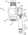
도 1은 본 발명의 바람직한 실시형태에 따른 다른 화재 방지 시스템 부품의 원격 기계적 작동을 위해 구성된 열 촉발형 어셈블리를 포함하는 건식 스프링클러 장치의 개략도이다;
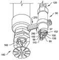
도 2는 본 발명의 바람직한 실시형태에 따른 활성화 부품에 의해 활성화되는 화재 방지 시스템 부품을 포함하는 건식 스프링클러 장치의 사시도이다;
도 3은 도 2의 건식 스프링클러 장치의 입면도이다;
도 4는 도 2의 장치의 밸브 부재 및 근위 기저부의 확대 및 부분 분해 사시도이다;
도 5는 도 2의 장치의 스프링클러 헤드 및 원위 기저부의 확대 부분 사시도이다;
도 6은 도 5의 스프링클러 헤드 및 원위 기부의 확대 부분 입면도이다;
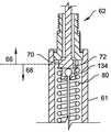
도 7은 예비 활성화 위치로 도시된, 도 2의 장치의 밸브 부품 및 근위 기저부의 확대 부분 입면도이다;
도 8은 활성화 위치로 도시된, 도 7의 밸브 부품 및 근위 기저부의 확대 부분 입면도이다;
도 9는 활성화 위치로 도시된, 도 2의 장치의 근위 기저부의 대안적인 실시 형태의 확대 부분 입면도;
도 10은 본 발명의 바람직한 실시형태에 따른 도관에 고정된 브래킷 및 원위 기저부의 부분 사시도이다; 및
도 11은 예비 활성화 위치로 도시된 본 발명의 바람직한 실시형태에 따른 밸브 부품의 부분 확대 입면도이다.The foregoing summary as well as the following detailed description of preferred embodiments of the present invention will be better understood when read in conjunction with the accompanying drawings. To illustrate the invention, a presently preferred embodiment is shown in the drawings. However, it should be understood that the invention is not limited to the precise arrangements and means shown. In the drawing:
1 is a schematic diagram of a dry sprinkler device comprising a heat triggered assembly configured for remote mechanical actuation of another fire protection system component according to a preferred embodiment of the present invention;
2 is a perspective view of a dry sprinkler device comprising a fire protection system component activated by an activation component according to a preferred embodiment of the present invention;
Figure 3 is an elevational view of the dry sprinkler device of Figure 2;
4 is an enlarged and partially exploded perspective view of the valve member and the proximal base of the device of FIG. 2;
5 is an enlarged partial perspective view of the sprinkler head and distal base of the device of FIG. 2;
6 is an enlarged partial elevational view of the sprinkler head and distal base of FIG. 5;
Fig. 7 is an enlarged partial elevational view of the proximal base and valve part of the device of Fig. 2, shown in a pre-activated position;
Fig. 8 is an enlarged partial elevational view of the proximal base and the valve component of Fig. 7, shown in the activated position;
9 is an enlarged partial elevational view of an alternative embodiment of the proximal base of the device of FIG. 2, shown in an activated position;
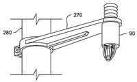
10 is a partial perspective view of a distal base and a bracket secured to a conduit according to a preferred embodiment of the present invention; And
11 is a partially enlarged elevational view of a valve component according to a preferred embodiment of the invention, shown in a pre-activated position.
특정 용어는 단지 편의를 위해 다음의 설명에서 사용되며, 이는 제한적인 것은 아니다. "하단(lower)", "하부(bottom)", "상단(upper)", "상부(top)", "전방(front)", "후방(back)" 및 "후진(rear)"이라는 단어는 도면에서 참조되는 방향을 지정한다. "내부로(inwardly)" 및 "외부로(outwardly)"라는 단어는 각각 본 개시에 따라 논의되는 구성 요소 및 이의 지정된 부품의 기하학적 중심을 향하고 그로부터 멀어지는 방향을 지칭한다. "근위(proximal)" 및 "원위(distal)"는 문맥이 달리 나타내지 않는 한, 각각 열 촉발형 어셈블리에 의해 촉발되는 화재 방지 시스템 부품을 향하고 멀어지는 일반적인 방향을 지칭한다. 본 명세서에서 구체적으로 언급되지 않는 한, 용어 "하나(a)", "하나(an)" 및 "그(the)"는 하나의 부품으로 제한되지 않고, 대신에 "적어도 하나(at least one)"를 의미하는 것으로 읽혀져야 한다. 용어는 상기 언급된 단어, 그 파생어 및 유사한 외래어를 포함한다.Certain terms are used in the following description for convenience only, and this is not limiting. The words "lower", "bottom", "upper", "top", "front", "back" and "rear" Designates the direction referred to in the drawing. The words "inwardly" and "outwardly" refer to a direction towards and away from the geometric center of a component and its designated part, respectively, discussed in accordance with this disclosure. "Proximal" and "distal" refer to the general direction towards and away from the fire protection system components triggered by the heat triggered assembly, respectively, unless the context indicates otherwise. Unless specifically stated herein, the terms “a”, “an” and “the” are not limited to one part, but instead “at least one” It should be read as meaning ". The term includes the words mentioned above, their derivatives and similar foreign words.
도 1에 도시된 바와 같이, 본 발명의 바람직한 실시형태의 블록도에서, 열 촉발형 어셈블리(10)는 다른 화재 방지 시스템 부품(16)의 원격 기계적 작동을 위해 구성된다. 열 촉발형 어셈블리(10)는 활성화 부품(12)과 상기 활성화 부품(12)이 다른 화재 방지 시스템 부품(16)을 원격 기계적 작동시키도록 구성된 가요성 연결부(14)를 포함하며, 이는 (하기에서 설명된) 일부 바람직한 실시형태에서 하나 또는 그 이상의 스프링클러, (리드 스위치(Reed switch) 또는 릴레이(relay)와 같은) 스위치 또는 스로우(throw), 마그넷(marnet)을 갖는 릴레이 또는 기계적으로 움직일 수 있는 유사체 또는 기계적 입력에 의해 작동 가능한 다른 유형의 화재 방지 시스템 장치로 물을 배출하는 밸브이다. 후술하는 바와 같이, 활성화 부품(12) 및 가요성 연결부(14)는 도 1의 블록도에 도시된 것과 동일한 방식으로 공간에 반드시 분배될 필요는 없다.As shown in FIG. 1, in a block diagram of a preferred embodiment of the present invention, a thermally triggered
다른 바람직한 실시형태에서, 도 2 내지 도 8에 도시된 바와 같이, 건식 스프링클러 장치는 도 2 내지 도 4, 도 7 및 도 8의 밸브(20)의 형태를 취하는 다른 화재 방지 시스템 부품의 원격 기계적 구조를 위해 구성된 열 촉발형 어셈블리를 포함한다. 열 촉발형 어셈블리는 다른 화재 시스템 부품(밸브(20))에 대해 몸통부(61), 근위 단부(62) 및 원위 단부(64)를 구비한 근위 기저부(60)를 포함하는 활성화 부품(50)을 포함한다. 일부 실시형태에서, 몸통부(61)의 원위 단부(64)에서 너트(63)는 (후술하는) 가요성 연결부(120)를 부착하기 위한 노치 피팅(63a)을 구비하여, 너트는 나사산(64a)과 맞물린다. 근위 이동형 부재(70)는 근위 기저부(60)에 대해 이동 가능하다. 도 7 및 도 8에 가장 잘 도시된 편향 부재는 코일 스프링(80)으로서 도시된다. 본 명세서에서 논의된 "편향 부재(bias member)"는 대안적으로 변위에 응답하여 복원력을 공급할 수 있는 다른 장치의 형태, 예를 들어, 공기 스프링 또는 판 스프링을 취할 수 있다. 편향 부재(코일 스프링(80))는 도 7에 도시된 바와 같이 근위 이동형 부재(70)를 근위 기저부(60)에 대해 예비 활성화 위치로부터 도 8에 도시된 바와 같이 근위 이동형 부재(70)를 근위 기저부(60)에 대해 활성화 위치로 편향시키도록 위치된다.In another preferred embodiment, as shown in Figures 2-8, the dry sprinkler device is a remote mechanical structure of another fire protection system component taking the form of the
활성화 위치는 예비 활성화 위치에 근접하여 위치하여, 근위 기저부(60)에 대한 예비 활성화 위치에서 활성화 위치로의 근위 이동형 부재(70)의 이동은 일반적으로 근접 이동이며, 즉, 다른 화재 방지 부품, 밸브(20)를 향한다(도 8에 도시된 바에 따르면 위로). 도 7에 도시된 예비 활성화 위치에서 근위 이동형 부재의 근위 단부(71)와 래치(32) 사이에 갭이 존재하는 것이 주목된다. 도 8에 도시된 활성화 위치에서 근위 이동형 부재(70)의 근위 단부(71)는 래치(32)와 접촉한다. 일부 실시형태에서, 근위 이동형 부재의 근위 단부(70a)는 다른 화재 방지 부품의 일부, 예를 들어, 밸브(20)의 래치(32)와 강제 충돌한다.The activation position is located close to the pre-activation position, so that the movement of the proximal
열 촉발형 어셈블리는 또한 원위 기저부(90), 당김부 형태의 원위 이동형 부재(100) 및 일부 실시형태에서 알코올이 충전된 유리 벌브이고, 열역학적 조건이 발생하거나 도달할 때까지 원위 기저부(90)에 의해 유지되는 열 반응형 부품(110)을 포함한다. 대안적으로, 특정 실시형태에서 원위 이동형 부재는 가요성 연결부 (120)의 단부 부분의 형태를 취할 수 있다.The heat-triggered assembly is also a
열 반응형 부품(110)은 소정의 열역학적 조건 하에서 구조적 완전성을 상실하도록 구성되며, 이에 의해 원위 이동형 부재(100)가 예비 활성화 위치로부터 원위 기저부(90)에 대해 일반적으로 근접하여 위치된 활성화 위치로(즉, 밸브(20)를 향해) 이동시킨다. 도 6을 참조하면, 원위 기저부(90)는 근위 단부(94), 원위 단부(96) 및 원위 단부로부터 원위로 연장되는 연장부(98)(도 6의 점선 박스 내에 있음)를 구비한 몸통부(92)를 포함하며, 연장부(98)는 열 반응형 부품(110)을 지지하는 암(99)을 포함한다. 원위 기저부(90)는 또한 본 실시형태에서 연장부(98)에 의해 지지되는 원위 기저부(90)에 의해 지지되는 받침대(97)를 포함한다.The thermally
도 2 내지 8을 다시 참조하면, 열 촉발형 어셈블리는 또한 근위 단부(122) 및 원위 단부(124)를 구비한 가요성 연결부(120)를 포함하고, 상기 근위 단부(122)는 근위 이동형 부재(70)에 연결되고, 상기 원위 단부(124)는 원위 이동형 부재(100)에 연결된다. 가요성 연결부(120)와 다른 부품 사이의 연결은 직접이거나, 가요성 연결부(120)와 예를 들어 근위 이동형 부재(70) 사이에 배치된 개재 연결 부품(intervening connecting component)을 이용하여 간접적일 수 있다. 예비 활성화 위치에서, 원위 기저부(90)에 대해 원위 이동형 부재, 당김부(100)를 유지하는 열 반응형 부품(110)은 또한 예비 활성화 위치에서, 근위 기저부(60)에 대해 근위 이동형 부재(70)를 유지한다. 열 반응형 부품(110)에 의한 구조적 완전성이 상실되면, 편향 부재(코일 스프링(80))로부터의 편향력은 근위 이동형 부재(70)의 예비 활성화 위치(도 7)으로부터 근위 이동형 부재(70)의 활성화 위치(도 8)로의 근위 이동형 부재(70)의 이동을 야기한다.2-8, the heat triggered assembly also includes a
가요성 연결부(120)는 근위 기저부(60)에 대해 고정식으로 연결되도록 구성된 근위 하우징 단부(128) 및 원위 기저부(90)에 대해 고정식으로 연결되도록 구성된 원위 하우징 단부(130)를 구비한 가요성 중공 외부 케이블 하우징(126)을 포함한다. 가요성 외부 케이블 하우징(126)은 둘 또는 그 이상의 이들의 부분을 연결하는 적어도 하나의 조인트(126a)를 포함할 수 있다. 가요성 연결부(120)는 또한 가요성 외부 케이블 하우징(126) 내의 이동을 위해 가요성 중공 외부 케이블 하우징(126) 내에서 위치하고, 근위 내부 부재 단부(134)(도 7) 및 원위 내부 부재 단부(136)(도 6)를 구비한 가요성 내부 부재(132)를 포함하고, 상기 근위 내부 부재 단부(134)는 근위 이동형 부재(70)와 고정식으로 연결되고, 원위 내부 부재 단부(136)는 원위 이동형 부재, 예시적인 실시형태에서 당김부(100)와 고정식으로 연결된다. 원위 이동형 부재는 당김부(100)에 대한 대안으로서, 가요성 연결부(120)와 결합된 다른 몸체부를 포함할 수 있으며, 다른 몸체부는 임의의 편리한 형상을 갖는다. 보다 일반적으로, 근위 내부 부재 단부(134)는 밀봉 부재(28)로부터 래치(32)에 의해 제공된 지지를 제거하기 위한 래치(32)와의 기계적 연결을 위해 구성되며, 이에 의해 유체가 밸브(20)의 유체 통로(40)를 통해 흐르도록 허용한다.The
도 5 및 도 6을 이하 참조하면, 플랫폼(150)은 받침대(97), 원위 이동형 부재(100) 및 열 반응형 부품(110)과 결합되어, 원위 이동형 부재(100) 및 열 반응형 부품(110)은 받침대(97) 위에 플랫폼(150)을 구속한다. 플랫폼(150)은 비교적 평평한 판으로 도시됨에도 불구하고, 본 발명에 따라 일반적으로 플랫폼(150)은 받침대(97)에 지지 가능하고 열 반응형 부품(110) 및 원위 이동형 부재(100)의 필요한 맞물림을 수용하는 임의의 형상을 취할 수 있다.5 and 6, the
(열역학적 조건의 발생으로 인한) 열 반응형 부품(110)의 구조적 완전성이 상실되면, 가요성 연결부(120)에 의해 전송되는 편향 부재(코일 스프링(80))로부터의 힘의 결과로서 플랫폼(150)은 받침대(97)를 중심으로 피봇팅하며, 원위 이동형 부재(100)를 원위 기저부(90)에 대한 활성화 위치로 이동시킨다. 바람직한 실시형태에서, 도 5 및 도 6에 도시된 바와 같이, 원위 이동형 부재는 가요성 연결부(120)의 원위 내부 부재 단부(136)에 부착된 당김부(100)의 형태를 취하고, 플랫폼(150)은 노치(152)를 구비하여, 당김부(100)와 맞물린다.If the structural integrity of the thermally responsive part 110 (due to the occurrence of thermodynamic conditions) is lost, the
예시적인 실시형태에서, 도 4, 도 7 및 도 8에 도시된 바와 같이. 밸브(20)는 유입구 단부(24)에 위치된 유입구(25), 배출구 단부(26)에 위치된 적어도 하나의 배출구(27) 및 유입구(25)와 배출구(27) 사이의 유체 통로(40)를 구비한 몸통부(22)를 포함한다. 유입구 단부(24)는 나사산(24a)을 구비하여, 유체 공급원에 부착된다. 몸통부(22)는 나사(23a)(하나가 도시됨)에 의해 부착된 착탈형 커버(23) (도 4)를 포함한다. 착탈형 커버는 나사산 개구부(23b)를 구비하여 나사산(62a)을 통해 근위 기저부(60)를 근위 단부(62)에 부착시킨다. 대안적인 실시형태에서, 밸브(20)는 유체 통로(40)와 유체 연통되는 추가 배출구(미도시)를 구비할 수 있음이 주목된다. 밀봉 부재(28)는 통로(40)를 가로 질러 지지 가능하여, 레버(30)에 의해 통로(40)를 폐쇄하며, 이는 교차 부재(36)에 위치된 레버 피봇(30a)에 의해 피봇식으로 장착된다. 레버(30)는 레버(30)와 맞물린 래치(32)에 의해 밀봉 위치로 유지된다. 근위 내부 부재 단부(134)는 래치(32)와 맞물리도록 구성되어, 도 8의 활성화 위치에서 근위 방향으로의 근위 내부 부재 단부(134)의 이동에 의해 레버(30)에 대해 래치(32)를 이동시킨다. 래치(32)는 교차 부재(36)에 위치된 래치 피봇(32a)에 의해 지지된다. 래치 편향 부재, 본 명세서에서 압축 작용을 하는 래치 스프링(32b)은 도 7의 예비 활성화 위치에 있을 때 레버(30)를 지지하는 위치에 래치(32)를 유지한다. 선택적으로 조정 나사(34)는 레버(30)와 샤프트 부분(28a)의 일 부분을 나사식으로 맞물리며, 이는 밀봉 부재(28)와 유입구(25)를 맞물리도록 조정하는 메카니즘을 제공하는 조합과 함께 밀봉 부재(28)를 지지한다. 보다 일반적으로, 가요성 연결부(120)의 근위 내부 부재 단부(134)는 직접 접촉을 통하거나 개재 부품을 통해 래치(32)와 맞물리도록 구성되어, 밀봉 부재(28)로부터 래치(32)에 의해 제공된 지지를 제거하며, 밀봉 부재(28)는 밸브(20)의 유입구(28)로부터 멀어지도록 이동함으로써, 유체가 유체 통로(40)를 통해 흐르도록 허용한다(도 8 참조).In an exemplary embodiment, as shown in FIGS. 4, 7 and 8. The
도 8을 참조하면, 활성화 위치의 근위 이동형 부재(70)는 밀봉부(170)에 의해 근위 기저부(60)와 밀봉되도록 맞물림된다.Referring to FIG. 8, the proximal
대안적으로, 도 9를 참조하면, 밀봉부(170)는 생략되고 근위 이동형 부재(70)는 근위 이동형 부재(70)에 대한 근위 기저부(60)의 몸통부(61)의 근위 부분(66)과 근위 이동형 부재(70)에 대한 근위 기저부(60)의 몸통부(61)의 원위 부분(68) 사이의 유체 연통을 허용하는 배수공(72)을 포함한다. 도 2 내지 도 8을 다시 참조하면, 근위 이동형 부재(70)는 근위 기저부(60)와 밀봉되도록 맞물리는 것이 유리하며, 활성화 부품(50)이 밸브(20)를 제어하도록 사용되어, 물이 스프링클러 헤드(180)로 흘러가도록 허용하며, 이는 스프링클러 헤드(180)의 제 2 열 반응형 부품(182)이 소정의 열역학적 조건 하에서 구조적 완전성을 상실(도 2 참조)할 때까지 폐쇄된 상태를 유지한다. 스프링클러 헤드(180)는 당업계에 현재 널리 알려진 임의의 광범위한 스프링클러 헤드, 또는 물 또는 다른 유체를 화재로 전달하기위한 임의의 다른 유형의 물-배출 장치를 포함할 수 있고, 개방형 스프링클러 헤드 및 유체가 흐르는 것을 차단하거나 허용하는 플러그 또는 다른 메카니즘을 구비한 스프링클러 헤드 모두를 포함할 수 있다. 이러한 부품들의 조합은 원위 기저부(90)의 열 반응형 부품 (110)과 스프링클러 헤드의 가용성 부재(182)로 도시된 열 반응형 부품 모두가 활성화되는 경우에만 스프링클러 헤드(180)를 통해 물이 흐르는 시스템을 형성한다. 열 반응형 부품(110) 단독으로 구조적 완전성을 상실하면, 밸브(20)가 개방되지만 물은 스프링클러 헤드(180)를 통해 흐를 수 없고; 또한 근위 기저부(60)와 근위 이동형 부재(70)의 밀봉적인 맞물림이 근위 기저부(60)를 통한 물의 흐름을 방지하거나 최소화한다.Alternatively, referring to FIG. 9, the
도 9의 실시형태에서, 근위 이동형 부재(70)의 배수공 통로(72)는 소량의 물이 근위 기저부(60)를 통해 흐르도록 허용하여, 스프링클러 헤드(180)의 작동 없이, 밸브(20) 단독의 촉발이 보다 용이하게 감지되며, 이는 물이 배수공 통로(72)를 통해 누출되어, 결국 활성화 부품(50)으로부터 누출되며, 원위 기저부(90) 부근에서 물이 감지될 수 있기 때문이다.In the embodiment of FIG. 9, the
도 10을 참조하면, 본 발명의 예시적인 실시형태에 따른 브래킷(270)은 도관(280) 상에 원위 기저부(90)를 지지한다.Referring to FIG. 10, a
도 11에 도시된 대안적인 실시형태에서, 다른 화재 부품(20)은 밸브(220)의 형태를 취할 수 있으며, 이는 많은 점에서 밸브(20)와 유사하다. 밸브(220)는 유입구(225), 배출구(227) 및 유입구(225)와 배출구(227) 사이의 유체 통로(240)를 구비한 몸통부(222)를 포함한다. 대안적인 실시형태에서, 밸브(220)는 유체 통로(240)와 유체 연통되는 추가 배출구(미도시)를 포함할 수 있음이 주목된다. 밀봉 부재(228)는 통로(240)를 가로 질러 지지 가능하여, 피봇식으로 장착된 레버(230)에 의해 통로(240)를 폐쇄하며, 레버(230)는 레버(230)와 결합될 수 있는 유리 벌브 형태의 취성 지지부(244)에 의해, 가요성 연결부, 도 11에 도시된 가요성 연결부의 근위 내부 부재 단부(134)의 이동이 유리 벌브(244)의 붕괴를 야기할 때까지, 밀봉 위치에 유지된다. 도시된 실시형태에서, 근위 내부 부재 단부(122)는 유리 벌브(244)에 힘을 전달함으로써 붕괴를 야기하고, 근위 이동형 부재는 가요성 연결부의 근위 내부 부재 단부(134)의 형태를 취한다. 레버(230)는 교차 부재(236) 상에 위치된 레버 피봇(230a)에 의해 교차 부재(236) 상에 피봇식으로 지지된다. 선택적으로, 조정 나사(234)는 레버(230)와 샤프브 부분(228a)를 나사식으로 맞물리며, 이는 차례로 밀봉 부재(28)와 유입구(25)를 맞물리도록 조정하는 메카니즘을 제공하는 조합과 함께 밀봉 부재(28)를 지지한다. 보다 일반적으로, 가요성 연결부(120)의 근위 내부 부재 단부(134)는 유리 벌브(244) 또는 다른 취성 지지부와 직접 접촉하거나 또는 개재 부품을 이용하여 맞물리도록 구성되어 밀봉 부재(228)로부터 지지를 제거함으로써, 유체가 통로(240)를 통하여 흐르도록 허용한다.In the alternative embodiment shown in FIG. 11, the
다른 대안적인 실시형태(미도시)에서, 가요성 내부 부재는 도 2 내지 도 8에 도시된 바와 같이 가요성 외부 케이블 하우징의 유무에 관계없이 도관의 외부가 아닌 도관(280)을 통해 통과될 수 있으며, 대안적인 실시형태에서 원위 기저부(90)는 도 2, 도 3 및 도 5의 스프링클러 헤드(180) 또는 도 6의 감축부에 의하여 점유된 위치나 근접하여 위치된다.In another alternative embodiment (not shown), the flexible inner member can be passed through the
도 2 내지 도 8을 다시 참조하면, 본 발명의 바람직한 실시형태에 따른 건식 스프링클러 장치는 밸브(20)의 적어도 하나의 배출구(27) 중 하나와 유체 연통하는 도관(280)을 추가로 포함한다. 건식 스프링클러 장치는 도관(280)과 유체 연통되는 스프링클러 헤드(180) 형태의 물 분배 장치를 추가로 포함하며, 스프링클러 헤드(180)는 유입구(184)와 도시된 실시형태에서 가용성 부재(120)이나 알코올이 충전된 벌브 형태 또는 열 반응형 부품의 임의의 적절한 형태를 취할 수 있는 제 2 열 반응형 부품에 의해 밀봉 위치에 유지된 유입구 플러그(186)로 밀봉된 배출구를 포함한다. 제 2 열 반응형 부품은 소정의 열역학적 조건이 발생하는 경우 구조적 완전성을 상실하도록 구성되어, 유체가 유입구(184)로부터 스프링클러 헤드(180)의 배출구를 통해 흐르도록 허용한다. 제 2 열 반응형 부품의 파괴를 위해 선택된 소정의 열역학적 조건은 반드시 그런 것은 아니지만 원위 기저부(90)의 열 반응형 부품(110)에 대해 선택된 조건과 상이한 소정의 열역학적 조건일 수 있음이 주목된다.Referring again to FIGS. 2 to 8, the dry sprinkler device according to a preferred embodiment of the present invention further comprises a
도 6을 참조하면, 현재 바람직한 실시형태에서, 건식 스프링클러 장치는 감축부(290)와 외부면(294)를 구비한 브래킷(292)을 포함하며, 브래킷(292)은 감축부(290)에 부착된다. 감축부(290)에 대한 브래킷(292)의 부착은 선택적으로 감축부(290)와 일체로 브래킷(290)을 형성하는 것을 포함할 수 있다. 바람직한 실시형태에서 배수공 통로(296)는 스프링클러 헤드(180)의 밀봉 부재(배출구 플러그 (186))의 근접하여 위치되며, 배수공 통로(296)는 도관(280) 및 브래킷(292)의 외부(294)과 유체 연통하며, 외부면(294)은 건식 스프링클러 장치의 외부 표면의 일부이다. 도 2 내지 도 8을 참조하면, 브래킷(290)의 배수공 통로(296)는 소량의 물이 브래킷(290)을 통해 흐르도록 허용하여, 스프링클러 헤드(180)의 촉발 없이, 밸브(20) 단독의 촉발이 보다 용이하게 검출되며, 이는 물이 브래킷(292)의 외부면(294)에(onto) 배수공 통로(296)를 통해 누출되기 때문이다.6, in the presently preferred embodiment, the dry sprinkler device includes a
본 발명의 실시형태에서, 근위 이동형 부재(70)의 이동은 편향 부재(코일 스프링(80))에 의하여 유발되며, 이는 밸브(20) 또는 다른 화재 시스템 부품(16) 근처의 가요성 연결부(120)의 근위 단부(122)에 위치된다. 이는 편향 부재가 가요성 연결부(120)의 원위 단부(124)에 위치된 구성보다 더 안정적인 작동을 초래하고, 이는 밸브(20) 또는 다른 화재 시스템 부품(16)을 작동시키기 위한 충분한 이동을 생성하기 위하여 가요성 연결부(120)의 임의의 변위를 극복해야 한다.In an embodiment of the present invention, the movement of the proximal
제어된 스프링클러 헤드 또는 다른 장치로부터 활성화 부품의 변위 능력은 화재 식별 및 대응을 위한 최적의 위치에서 활성화 부품의 유리한 위치를 허용하고, 물 분배 및/또는 적용을 위해 최적의 위치(들)에 연결된 스프링클러(들)를 배치한다.The ability of the active component to displace from a controlled sprinkler head or other device allows an advantageous location of the active component in the optimal location for fire identification and response, and the sprinkler connected to the optimal location(s) for water distribution and/or application. Place(s).
본 발명 장치의 또 다른 가능한 용도는 목재 구조물의 다락(attic) 및 다른 가연성 은폐 영역에서 장애물의 유무에 관계없이 화재 방지를 제공하는 것이다.Another possible use of the inventive device is to provide fire protection with or without obstacles in the attic and other combustible concealment areas of wooden structures.
본 발명의 많은 실시형태는 지금까지 다락 사용에 대하여 이용할 수 없었거나 화재 시험을 통과할 수 없었던 다수의 가능한 스프링클러 옵션을 제공한다. 본 발명의 시스템의 활성화 부품은 지붕의 정점에 위치하거나, 가장 빠른 활성화를 위해 가장 신속하게 화재로부터 열을 감지하는 데 최적인 곳마다 위치할 수 있으며, 밸브 부품을 통해 활성화 부품과 연결되는 스프링클러 헤드(들)는 최적의 물 분배를 얻거나 및/또는 잠재적인 화재원에 더 가까이 위치하기 위해 최고의 보호 또는 설치(피크(peak)에서, 피크로부터 멀리 및/또는 피치(pitch)로부터 멀리)를 제공할 수 있는 곳마다 위치될 수 있다.Many embodiments of the present invention provide a number of possible sprinkler options that have hitherto been unavailable for attic use or have not been able to pass fire tests. The activating part of the system of the present invention can be located at the apex of the roof, or wherever it is optimal to detect heat from fire most quickly for the fastest activation, and the sprinkler head connected to the activating part through a valve part. (S) provide the best protection or installation (at peak, away from peak and/or away from pitch) to obtain optimal water distribution and/or to be located closer to potential fire sources. It can be located wherever it can.
본 발명의 특정 실시형태는 플러그 또는 열 반응형 부품 없이 개방형 구성이지만, 이러한 위치에 임의의 및 모든 유형의 종래의 스프링클러 헤드(펜던트(pendent) 및 측벽(sidewall) 뿐만 아니라 수직 및 표준 스프레이)의 설치를 가능하게 한다. 본 발명의 제공은 추가로 그러한 적용(들)에 적합한 다른 신규한 개념의 스프레이 분배 방법 및 스프링클러 헤드의 개발을 가능하게 한다. 또한, 종래의 자동 스프링클러 헤드는 최대 열거된 적용 범위 영역 (또는 정상적인 경우 열거된 적용 범위가 130 스퀘어 피트를 초과하는 경우 최소 130 스퀘어 피트 이상)에 따르고 및 다락 및 다른 가연성 은폐 설비에 사용되는 기존의 자동 스프링클러에 현재 부과되는 유압 수요 페널티 없이 설치 가능하다. 본 발명의 밸브 부품에 연결된 개방 스프링클러 헤드는 또한 수직으로부터 설치(pitch)되어 필요에 따라 또는 원하는 경우에 스로우 패턴(throw patter)을 향상시킨다. 본 발명의 일부 실시형태는 또한 현재 필요한 것보다 적은 물을 사용할 수 있는 기회를 제공하며, 이는 표준 스프링클러 방식의 단일 장치에 의해 제공되는 것보다 기능이 분리되어, 본 발명의 실시형태가 활성화를 위한 활성화 부품의 최적 배치 뿐만 아니라 화재 방지를 위한 스프레이 스프링클러의 최적 배치를 제공하기 때문이다.Certain embodiments of the invention are open configurations without plugs or thermally responsive parts, but installation of any and all types of conventional sprinkler heads (pendents and sidewalls as well as vertical and standard sprays) in these locations. Makes it possible. The provision of the present invention further enables the development of sprinkler heads and other novel concept spray dispensing methods suitable for such application(s). In addition, conventional automatic sprinkler heads conform to the maximum enumerated coverage area (or at least 130 sq ft if the enumerated coverage exceeds 130 sq ft in normal cases) and are used in attic and other flammable concealment installations. It can be installed without the hydraulic demand penalty currently imposed on automatic sprinklers. The open sprinkler head connected to the valve component of the present invention is also pitched from vertical to improve the throw pattern as needed or if desired. Some embodiments of the present invention also provide the opportunity to use less water than is currently needed, which is more functional than provided by a single unit of standard sprinkler system, allowing embodiments of the present invention for activation. This is because it provides the optimal placement of the active parts as well as the spray sprinkler for fire protection.
이들 장점은 또 다른 "문제 영역"에 설치된 스프링클러 시스템에서 이용 가능하다. 따라서, 본 발명의 특정 실시형태는 종래의 개방형 자동 스프링클러 헤드를 사용하면서 건식 다락 스프링클러 시스템의 설치를 가능하게 한다. 밸브 부품은 활성화 부품 및 헤드가 위치될 수 있는 추운 영역이나 물에 민감한 영역(water-sensitive area)으로부터 이격된 가열된 영역 또는 물에 민감하지 않은 영역(non-water-sensitive area)에 위치될 수 있다. 대안적으로, 가열된 영역 또는 물에 민감하지 않은 영역과 활성화 부품 사이의 거리가 프리액션(preaction) 밸브 어셈블리의 가요성 연결부의 길이 보다 큰 곳에서의 가열된 영역 또는 물에 민감하지 않은 영역의 상측(upstream)에 위치된 건조 밸브를 제공함으로써, 추운 영역 또는 물에 민감한 영역에 위치된 본 발명의 프리액션 밸브 어셈블리에 물이 제공될 수 있다.These advantages are available for sprinkler systems installed in another "problem area". Thus, certain embodiments of the present invention enable the installation of dry attic sprinkler systems while using conventional open automatic sprinkler heads. The valve part may be located in a cold or non-water-sensitive area away from a water-sensitive area or a cold area where the active part and head can be located. have. Alternatively, in a heated area or in a water insensitive area where the distance between the heated area or the water insensitive area and the active part is greater than the length of the flexible connection of the preaction valve assembly. By providing a drying valve located upstream, water can be provided to the pre-action valve assembly of the present invention located in a cold or water sensitive area.
최종적으로, 본 발명의 밸브 부품에 의해 공급된 스프링클러 헤드의 제공은 화재원에 충분히 신속하고 충분히 근접하게 물을 배출하여, 화재를 진압하도록 헤드의 최적 위치를 허용하여, 적용 영역의 스퀘어 피트당 분당 0.1 갤런 미만의 전달된 수분 밀도로 시험 기관 화재 테스트를 통과할 수 있다.Finally, the provision of the sprinkler head supplied by the valve component of the present invention discharges water sufficiently quickly and sufficiently close to the fire source, allowing the optimum position of the head to extinguish the fire, per minute per square foot of application area. Delivered moisture densities of less than 0.1 gallon can pass laboratory fire tests.
다른 적용은 동결 조건하에 있는 트럭 로딩 도크(truck loading dock)의 화재 방지이다. 본 발명의 열 촉발형 어셈블리의 특정 실시형태는 동결 영역에 설치된 기존의 승인된 종래 개방형 스프링클러를 사용하고, 가열된 영역에 밸브 부품을 설치함으로써, 매우 비싸고 복잡한 건식 스프링클러 시스템을 대체할 수 있다. 이 개념은 본 발명의 실시형태에 의해 허용되는 속도 및 전략적 위치로 인해 일반적인 위험 수분 밀도의 감소가 경 위험 요건(50 % 초과의 물이 덜 함유(over 50% less water))으로 낮아질 수 있게 한다.Another application is fire protection for truck loading docks under freezing conditions. Certain embodiments of the heat-triggered assembly of the present invention can replace a very expensive and complex dry sprinkler system by using an existing approved conventional open sprinkler installed in the frozen zone and installing valve components in the heated zone. This concept allows the reduction in general hazardous moisture density to be lowered to light hazard requirements (over 50% less water) due to the speed and strategic location allowed by embodiments of the present invention. .
임의의 종래 자동 스프링클러 헤드를 건식 스프링클러 장치에 설치할 수 있다는 것은 그 자체로 중요한 장점이다. 종래 건식 스프링클러 시스템의 설치자는 종래 건식 스프링클러를 주문하기 위해 특정 길이 외에도 배향(orentation)(측벽, 수직 또는 펜던트 및 펜던트인 경우 노출된, 오목하거나 숨겨진), 작동 온도, 오리피스 크기, 마감 및/또는 색상을 포함하는 다른 특성을 구체화해야 한다. 이러한 특성의 수천 가지 잠재적 조합을 만족시키기 위해, 본 발명의 밸브 부품과 함께 선반에서 사용될 수 있는 다양한 제조업체로부터 이용 가능한 상이한 종래의 자동 스프링클러 헤드는 실제로 수백 가지 어쩌면 수천 가지이다. 본 발명의 건식 스프링클러 장치의 밸브 부품만이 공인된 시험 기관의 승인을 필요로 하기 때문에, 본 발명의 밸브 부품으로 사실상 임의의 종래 자동 스프링클러 헤드(개방형 또는 플러그형)를 제한없이 설치하여 건식 시스템을 제공할 수 있다.Being able to install any conventional automatic sprinkler head into a dry sprinkler device is a significant advantage in itself. To order a conventional dry sprinkler system, the installers can order a conventional dry sprinkler, in addition to the specific length, orientation (exposed, concave or hidden for sidewalls, vertical or pendants and pendants), operating temperature, orifice size, finish, and/or color. Other properties, including: To satisfy thousands of potential combinations of these properties, there are actually hundreds or maybe thousands of different conventional automatic sprinkler heads available from various manufacturers that can be used in lathes with the valve parts of the present invention. Since only the valve parts of the dry sprinkler device of the present invention require approval from an accredited testing agency, virtually any conventional automatic sprinkler head (open type or plug type) is installed without limitation as the valve part of the present invention to provide a dry system. Can provide.
화재 스프링클러에 대한 가능한 상이한 특성 조합이 실제로 수백 가지 어쩌면 수천 가지이며, 많은 제조업체는 자동 스프링클러 헤드에 이러한 조합을 상업적으로 제공할 것이고, 그들은 건식 스프링클러에서 이러한 특징적인 조합의 약 10 분의 1만 공급할 것이며, 이는 각각의 건식 스프링클러는 승인 시험 기관에서 작동, 부식 및 기타 성능 특성에 대해 개별적으로 테스트를 받아야 하기 때문이다. 공인된 테스트 시험 기관 중 한 곳의 승인을 위하여 테스트를 위한 각각의 건식 스프링클러의 비용이 $10,000 이상인 경우, 제조업체는 시장이 이용 가능한 습식 시스템 스프링클러 헤드의 모든 범위에 대한 승인 비용을 정당화하기에 크지 않기 때문에, 이용 가능한 건식 스프링클러의 종류를 제한한다. 일단 승인되면, 본 발명의 열 촉발형 어셈블리를 구비한 프리액션 밸브는 모든 제조업체의 사실상 모든 시험 기관-승인 종래 자동 스프링클러 헤드에 건식 스프링클러 장치로서 설치되도록 허용한다. 이를 통해 스프링클러 시스템 설계자, 건물 소유주 및 설치업체에게 설치 비용을 또한 절약할 수 있는 사용을 위해 스프링클러 헤드의 거의 무제한적인 선택을 제공한다.There are actually hundreds or maybe thousands of different combinations of properties for fire sprinklers, and many manufacturers will commercially offer these combinations for automatic sprinkler heads, and they will only supply about a tenth of these characteristic combinations in dry sprinklers. This is because each dry sprinkler must be individually tested for operation, corrosion and other performance characteristics by an approved testing laboratory. If the cost of each dry sprinkler for testing is more than $10,000 for approval by one of the accredited testing laboratory, the manufacturer is not large enough to justify the cost of approval for the full range of wet system sprinkler heads available on the market. , Limit the type of dry sprinkler available. Once approved, the pre-action valve with the heat triggered assembly of the present invention allows installation as a dry sprinkler device in virtually all laboratory-approved conventional automatic sprinkler heads from all manufacturers. This gives sprinkler system designers, building owners and installers an almost unlimited choice of sprinkler heads for use that can also save installation costs.
본 발명의 밸브 부품은 기계적으로 작동(trip)될 수 있기 때문에, 이들은 또한 개별적으로 원격 작동되거나, 자동으로 또는 필요에 따라 구성되거나 접근될 수 있다.Since the valve parts of the invention can be mechanically tripped, they can also be individually remotely operated, automatically configured or accessed as needed.
본 발명의 열 촉발형 어셈블리는 플러그형 스프링클러 헤드의 온도와 비교하여 낮거나 높도록 활성화 부품의 열 반응형 부품의 작동 온도의 선택에 의해 연결된 자동(즉, 플러그형) 스프링클러 헤드(들)의 정격 온도 미만, 초과 또는 동등한 온도에서 자동으로 작동되도록 구성될 수 있다. 따라서, 원하는 경우, 스프링클러 헤드를 활성화하기 전에 스프링클러 헤드에 물을 예비 로딩하거나, 스프링클러 헤드가 개방된 후까지 로딩을 지연시킬 수 있다.The thermally triggered assembly of the present invention is rated for the automatic (i.e. pluggable) sprinkler head(s) connected by selection of the operating temperature of the thermally responsive part of the active part to be low or high compared to the temperature of the pluggable sprinkler head. It can be configured to operate automatically at below, above, or equivalent temperatures. Therefore, if desired, water may be preloaded on the sprinkler head before activating the sprinkler head, or the loading may be delayed until after the sprinkler head is opened.
2단계 활성화를 제공하기 위해 사용될 때, 본 발명의 열 촉발형 어셈블리는 또한 파손 또는 우발적 손상, 허위 작동 또는 오작동 및 누수(보험회사 및 건물 소유주 모두의 주요 관심사)에 대한 우수한 보호를 제공한다. 스프링클러가 정상적인 작동 전에 손상을 입는 경우(예를 들어, 벌브 또는 기타 열 반응형 부품이 파괴되거나 실수로 파손되거나 결함이 있는 경우(즉, 누출 허용)), 더 이상 물이 방출되지 않을 것이며, 이는 본 발명의 "독립적인" 활성화 부품이 스프링클러에 대한 손상에 의해 유발되지 않기 때문이다. 이를 통해 의도하지 않은 활성화로 인한 물 손상을 방지할 뿐만 아니라 시스템을 보호 서비스에서 시스템을 제거하지 않고, 공장에서 제조한 교체 어셈블리를 기다릴 필요 없이 즉시 현장 수리를 허용한다. 본 시스템은 기존의 습식 시스템과 같이 현장에서 완전히 수리될 수 있다. (헤드 수리 중 활성 시스템을 유지 관리하는 데는 정교한 장비가 필요하기 때문에 비용이 매우 많이 소요된다.)When used to provide two-step activation, the thermally triggered assemblies of the present invention also provide excellent protection against breakage or accidental damage, spurious operation or malfunction, and leaks (a major concern for both insurance companies and building owners). If the sprinkler is damaged prior to normal operation (e.g., if the bulb or other thermally responsive part is destroyed, accidentally broken or defective (i.e. leaks are allowed)), no more water will be released, which means This is because the "independent" active part of the invention is not caused by damage to the sprinkler. This not only prevents water damage due to unintentional activation, but also allows immediate on-site repair without having to remove the system from protection service and without having to wait for a factory-made replacement assembly. The system can be fully repaired in the field just like a conventional wet system. (Maintaining the active system during head repair is very expensive because sophisticated equipment is required.)
자동 (즉, 플러그형) 스프링클러 헤드를 구비한 시스템의 열 촉발형 어셈블리가 스프링클러 작동 전에 밸브 부품을 개방하도록 구성되면, 스프링클러 헤드로부터 물이 흐르기 전에 빠져나갈 공기가 없기 때문에 화재 방지가 개선된다. 밸브 부품은 스프링클러 헤드의 작동 온도에 도달하는 조건 전에 스프링클러 헤드를 미리 채운다.If the heat-triggered assembly of a system with an automatic (i.e. pluggable) sprinkler head is configured to open the valve component prior to sprinkler actuation, fire protection is improved as there is no air to escape before the water flows from the sprinkler head. The valve component is prefilled with the sprinkler head prior to the condition reaching the operating temperature of the sprinkler head.
본 발명의 열 촉발형 어셈블리를 구비한 프리액션 밸브는, 밸브 부품이 동결 온도로부터 보호된 영역 및/또는 그렇지 않으면 동결 온도에 노출되지 않은 영역에 위치될 수 있다면, 플라스틱 배관이 일반적으로 건식 스프링클러를 필요로 하는 영역에서 드롭으로서 사용되도록 허용한다. 이는 특히 플라스틱 배관 설치가 전체적으로 가능한 주거 및 경(light) 위험 시스템에서 설치 시간과 비용을 크게 절약하는 것을 나타낸다. 본 어셈블리는, 임의의 자동(즉, 플러그형) 스프링클러에 사용된 열 반응형 부품이 활성화되어, 활성화 부품과 스프링클러 모두의 열 반응형 부품이 이들 각각의 활성화 온도에 도달할 때까지 드롭 내에 물 및 드롭의 가압이 없음을 보장하기 위한 온도를 초과하여 작동시키기 위한 열 반응형 부품의 선택에 의해, 구성될 수 있다.Preaction valves with the heat triggered assembly of the present invention, plastic tubing is generally used in dry sprinklers, provided that the valve component can be placed in an area protected from freezing temperatures and/or otherwise not exposed to freezing temperatures. Allows to be used as a drop in the required area. This represents a significant savings in installation time and cost, especially in residential and light hazard systems where plastic piping installation is entirely possible. This assembly allows the thermally responsive component used in any automatic (i.e. pluggable) sprinkler to be activated so that both the active component and the thermally responsive component of the sprinkler have water and water in the drop until they reach their respective activation temperatures. It can be configured by the selection of thermally responsive parts to operate above the temperature to ensure there is no pressurization of the drop.
활성화 부품(12)이 상기 반응형 부품(110) 또는 그 동등물의 파손으로부터 작동되지만 자동(즉, 플러그형) 스프링클러(180)가 활성화되지 않으면, 활성화 부품의 노출된 부분, 예를 들어 원위 기저부(90)는 상기 설명된 바와 같이, 활성화 부품이 작동되고 물이 잠재적으로 동결되는 영역에 있다는 것을 천장 아래에서 시각적으로 표시할 것이며, 또한 하나 또는 그 이상의 배출공 통로(72, 296)를 통한 누출에 의한 표시를 제공할 것이다. 스프링클러가 누출된 경우, 드롭 배관에 물이 가득 차서 서비스를 받아야 한다는 경고가 2차 표시될 것이다.If the activating
본 발명의 열 촉발형 어셈블리는 압축 가스 및 부동액 "건식" 스프링클러에 대한 매우 경제적인 대안을 제공하는 것 외에도, 부동산 소유자를 위한 손상으로부터 추가적인 보안을 제공하는 2단계 작동을 구비한 경제적인 건식 주거용 스프링클러 시스템의 가능성을 추가로 제시할 수 있다.In addition to providing a very economical alternative to compressed gas and antifreeze "dry" sprinklers, the heat triggered assembly of the present invention is an economical dry residential sprinkler with two-stage operation that provides additional security from damage for property owners. Additional possibilities of the system can be presented.
본 기술 분야에서 당업자는 본 발명의 광범위한 개념을 벗어나지 않고 전술 한 실시형태를 변경할 수 있음을 이해할 것이다. 그러므로, 본 개시는 개시된 특정 실시형태들로 제한되지 않으며, 첨부된 청구범위에 의해 정의된 바와 같이 본 개시의 사상 및 범위 내에서의 변형을 포함하도록 의도된다.Those skilled in the art will appreciate that the above-described embodiments can be changed without departing from the broad concept of the present invention. Therefore, this disclosure is not limited to the specific embodiments disclosed, but is intended to cover variations within the spirit and scope of the disclosure as defined by the appended claims.
Claims (28)
Translated fromKorean화재 방지 시스템 부품에 대해 근위 단부 및 원위 단부를 가지는 근위 기저부;
근위 기저부에 대해 이동 가능한 근위 이동형 부재;
근위 기저부 보다 화재 방지 시스템 부품으로부터 멀리 위치된 원위 기저부;
원위 이동형 부재;
근위 기저부에 대해 위치되어, 근위 이동형 부재를 근위 기저부에 대해 예비 활성화 위치로부터 활성화 위치로 편향시키고, 상기 활성화 위치는 예비 활성화 위치의 상류측에 위치되는 편향 부재;
소정의 열역학적 조건이 발생할 때까지 원위 기저부에 의해 유지되고, 소정의 열역학적 조건 하에서 구조적 완전성을 상실하여, 원위 이동형 부재를 원위 기저부에 대해 예비 활성화 위치로부터 활성화 위치로 이동시키도록 구성된 열 반응형 부품; 및
근위 단부 및 원위 단부를 가지고, 상기 근위 단부는 근위 이동형 부재에 연결되고, 상기 원위 단부는 원위 이동형 부재에 연결되어, 열 반응형 부품이 원위 이동형 부재를 원위 기저부에 대해 예비 활성화 위치에 유지시키고, 또한, 근위 이동형 부재를 근위 기저부에 대해 예비 활성화 위치에 유지시켜, 열 반응형 부품에 의해 구조적 완전성의 상실시 편향 부재로부터의 편향력이 근위 이동형 부재의 예비 활성화 위치로부터 근위 이동형 부재의 활성화 위치로의 근위 이동형 부재의 이동을 야기하는 가요성 연결부를 구비한 활성화 부품을 포함하는 열 촉발형 어셈블리.A heat-triggered assembly configured for remote mechanical operation of fire protection system components,
A proximal base having a proximal end and a distal end to the fire protection system component;
A proximal moveable member movable relative to the proximal base;
A distal base located further from the fire protection system component than the proximal base;
Distal movable member;
A biasing member positioned relative to the proximal base to bias the proximal movable member from a pre-activation position to an activation position with respect to the proximal base, the activation position being positioned upstream of the pre-activation position;
A thermally responsive part that is held by the distal base until a certain thermodynamic condition occurs and is configured to move the distal movable member from the pre-activation position to the activating position relative to the distal base by losing structural integrity under the pre-determined thermodynamic condition; And
Having a proximal end and a distal end, said proximal end connected to a proximal movable member, said distal end connected to a distal movable member such that the thermally responsive part holds the distal movable member in a pre-activated position relative to the distal base, In addition, by keeping the proximal movable member in a pre-activated position with respect to the proximal base, the biasing force from the biasing member in the event of loss of structural integrity by the thermally responsive part is transferred from the pre-activated position of the proximal movable member to the activated position of the proximal movable member. A heat triggered assembly comprising an activating component having a flexible connection that causes movement of the proximal moveable member of the.
상기 가요성 연결부는:
근위 기저부에 대해 고정식으로 연결되도록 구성된 근위 하우징 단부와 원위 기저부에 대해 고정식으로 연결되도록 구성된 원위 하우징 단부를 구비한 가요성 중공 외부 케이블 하우징; 및
가요성 외부 케이블 하우징 내에서의 이동을 위해 가요성 중공 외부 케이블 하우징 내부에 위치되고, 근위 내부 부재 단부 및 원위 내부 부재 단부를 가지며, 상기 근위 내부 부재 단부는 근위 이동형 부재에 고정식으로 연결되고, 상기 원위 내부 부재 단부는 원위 이동형 부재에 고정식으로 연결되는 가요성 내부 부재를 포함하는 열 촉발형 어셈블리.The method of claim 1,
The flexible connection part:
A flexible hollow outer cable housing having a proximal housing end configured to be fixedly connected to the proximal base and a distal housing end configured to be fixedly connected to the distal base; And
It is located inside the flexible hollow outer cable housing for movement within the flexible outer cable housing and has a proximal inner member end and a distal inner member end, the proximal inner member end being fixedly connected to the proximal movable member, the The distal inner member end is a heat triggered assembly comprising a flexible inner member fixedly connected to the distal moveable member.
화재 방지 시스템 부품은
몸체부,
개방 상태,
폐쇄 상태,
환형 밀봉부,
폐쇄 상태에서 환형 밀봉부를 지지하도록 구성된 샤프트, 및
폐쇄 상태에서 샤프트를 지지하도록 구성되고, 샤프트를 지지하는 레버를 포함하는 지지체 어셈블리를 가지는 밸브이고,
근위 이동형 부재는 지지체 어셈블리에 작동하도록 연결되어, 근위 이동형 부재의 이동이 지지체 어셈블리에 작용하여, 레버가 이동하고 밸브가 폐쇄 상태에서 개방 상태로 변경되는 열 촉발형 어셈블리.The method of claim 1,
Fire protection system parts are
Body,
openness,
Closed state,
Annular seal,
A shaft configured to support the annular seal in a closed state, and
A valve configured to support the shaft in a closed state and having a support assembly comprising a lever for supporting the shaft,
The proximal movable member is operatively connected to the support assembly, such that movement of the proximal movable member acts on the support assembly such that the lever moves and the valve changes from a closed state to an open state.
상기 근위 이동형 부재는 레버로부터 래치를 해제함으로써 레버의 이동을 야기하는 열 촉발형 어셈블리.The method of claim 3,
The proximal moveable member causes the lever to move by releasing the latch from the lever.
상기 근위 이동형 부재는 압축력을 래치가 아닌 부품에 전달함으로써 레버의 이동을 야기하는 열 촉발형 어셈블리.The method of claim 3,
The proximal movable member is a heat triggered assembly that causes movement of the lever by transmitting a compressive force to a component other than the latch.
화재 방지 시스템 부품은
몸체부,
개방 상태,
폐쇄 상태,
환형 밀봉부,
폐쇄 상태에서 환형 밀봉부를 지지하도록 구성된 샤프트, 및
폐쇄 상태에서 샤프트를 지지하도록 구성되고, 샤프트를 지지하는 레버를 포함하는 지지체 어셈블리를 가지는 밸브이고,
상기 레버는 근위 이동형 부재의 이동이 취성 지지부의 붕괴를 야기할 때까지 레버와 결합된 취성 지지부에 의해 밀봉 위치에 유지되는 열 촉발형 어셈블리.The method of claim 1,
Fire protection system parts are
Body,
openness,
Closed state,
Annular seal,
A shaft configured to support the annular seal in a closed state, and
A valve configured to support the shaft in a closed state and having a support assembly comprising a lever for supporting the shaft,
Wherein the lever is held in the sealed position by the brittle support associated with the lever until movement of the proximal moveable member causes the brittle support to collapse.
상기 가요성 연결부는:
근위 기저부에 대해 고정식으로 연결되도록 구성된 근위 하우징 단부와 원위 기저부에 대해 고정식으로 연결되도록 구성된 원위 하우징 단부를 구비한 가요성 중공 외부 케이블 하우징; 및
가요성 외부 케이블 하우징 내에서의 이동을 위해 가요성 중공 외부 케이블 하우징 내부에 위치되고, 근위 내부 부재 단부 및 원위 내부 부재 단부를 가지며, 상기 근위 내부 부재 단부는 근위 이동형 부재에 고정식으로 연결되고, 상기 원위 내부 부재 단부는 원위 이동형 부재에 고정식으로 연결되는 가요성 내부 부재를 포함하며,
근위 내부 부재 단부는 힘을 취성 지지부에 전달함으로써, 붕괴를 야기하는 열 촉발형 어셈블리.The method of claim 6,
The flexible connection part:
A flexible hollow outer cable housing having a proximal housing end configured to be fixedly connected to the proximal base and a distal housing end configured to be fixedly connected to the distal base; And
It is located inside the flexible hollow outer cable housing for movement within the flexible outer cable housing and has a proximal inner member end and a distal inner member end, the proximal inner member end being fixedly connected to the proximal movable member, the The distal inner member end includes a flexible inner member fixedly connected to the distal movable member,
The proximal inner member end transfers force to the brittle support, thereby causing collapse.
취성 부품의 붕괴를 야기하는 힘은 근위 이동형 부재에 의해 가해지는 압축력인 열 촉발형 어셈블리.The method of claim 7,
A heat-triggered assembly where the force that causes the brittle component to collapse is the compressive force exerted by the proximal moving member.
활성화 위치의 근위 이동형 부재는 근위 기저부에 밀봉되도록 맞물리고, 근위 이동형 부재는 근위 이동형 부재에 대해 근위 기저부의 몸통부의 근위 부분과 근위 이동형 부재에 대해 근위 기저부의 몸통부의 원위 부분 사이의 유체 연통을 허용하는 배출공 경로를 포함하는 열 촉발형 어셈블리.The method of claim 1,
The proximal movable member in the active position engages sealingly at the proximal base, and the proximal movable member allows fluid communication between the proximal portion of the trunk of the proximal base relative to the proximal movable member and the distal portion of the trunk of the proximal base for the proximal movable member. Heat-triggered assembly including an exhaust hole path.
원위 기저부는:
근위 단부, 원위 단부, 및 원위 단부로부터 원위로 연장되며, 열 반응형 부품을 지지하는 연장부를 구비한 몸체부,
몸체부에 의해 지지되는 받침대,
받침대, 원위 이동형 부재 및 열 반응형 부품과 맞물리는 플랫폼을 포함하며, 원위 이동형 부재와 열 반응형 부품이 플랫폼을 받침대 상에 구속시키고, 열 반응형 부품의 구조적 완전성의 손상시 플랫폼이 받침대를 중심으로 피봇팅하여, 원위 이동형 부재를 원위 기저부에 대해 활성화 위치로 이동시키는 열 촉발형 어셈블리.The method of claim 1,
The distal base is:
A body portion having a proximal end, a distal end, and an extension extending distally from the distal end and supporting a thermally responsive part,
A pedestal supported by the body,
It includes a pedestal, a distal movable member, and a platform that engages with the thermally responsive parts, and the distal movable member and the thermally responsive part restrain the platform on the pedestal, and the platform centers around the pedestal when the structural integrity of the thermally responsive component is impaired. A heat triggered assembly that pivots to move the distal movable member to an active position relative to the distal base.
원위 이동형 부재는 가요성 연결부에 부착된 당김부를 포함하고, 플랫폼은 당김부에 맞물리는 노치를 구비한 열 촉발형 어셈블리.The method of claim 10,
The distal movable member includes a pull attached to the flexible connection, and the platform has a notch that engages the pull.
기계적 이동에 의해 작동되도록 구성된 화재 방지 시스템 부품;
화재 방지 시스템 부품에 대해 근위 단부 및 원위 단부를 구비한 근위 기저부,
근위 기저부에 대해 이동 가능한 근위 이동형 부재,
근위 기저부보다 화재 방지 시스템 부품으로부터 멀리 위치된 원위 기저부,
원위 이동형 부재,
근위 기저부에 대해 위치되고, 근위 이동형 부재를 근위 기저부에 대해 예비 활성화 위치로부터 활성화 위치로 편향시키고, 상기 활성화 위치는 예비 활성화 위치에 대해 근위 방향을 향해 위치되고, 근위 방향은 원위 기저부로부터 근위 기저부로 향하는 편향 부재,
소정의 열역학적 조건이 발생할 때까지 원위 기저부에 의해 유지되고, 소정의 열역학적 조건 하에서 구조적 완전성을 상실하여, 원위 이동형 부재를 원위 기저부에 대해 예비 활성화 위치로부터 활성화 위치로 이동시키도록 구성된 열 반응형 부품, 및
근위 단부 및 원위 단부를 가지며, 상기 근위 단부는 근위 이동형 부재에 연결되고, 상기 원위 단부는 원위 이동형 부재에 연결되어, 열 반응형 부품이 원위 이동형 부재를 원위 기저부에 대해 예비 활성화 위치에 유지시키고, 또한, 상기 근위 이동형 부재를 근위 기저부에 대해 예비 활성화 위치에 유지시켜, 열 반응형 부품에 의해 구조적 완전성의 상실시, 편향 부재로부터의 편향력이 근위 이동형 부재의 예비 활성화 위치로부터 근위 이동형 부재의 활성화 위치로의 근위 이동형 부재의 이동을 야기하는 가요성 연결부를 구비한 활성화 부재를 포함하고,
화재 방지 시스템 부품은
몸체부,
개방 상태,
폐쇄 상태,
환형 밀봉부,
폐쇄 상태에서 환형 밀봉부를 지지하도록 구성된 샤프트, 및
폐쇄 상태에서 샤프트를 지지하도록 구성되고, 샤프트를 지지하는 레버를 포함하는 지지체 어셈블리를 가지는 밸브이고,
근위 이동형 부재는 지지체 어셈블리에 작동하도록 연결되어, 근위 이동형 부재의 이동이 지지체 어셈블리에 작용하여 레버를 이동시켜, 밸브가 폐쇄 상태에서 개방 상태로 변경되는 건식 스프링클러 장치.As a dry sprinkler device,
Fire protection system components configured to be operated by mechanical movement;
A proximal base with a proximal end and a distal end to the fire protection system component,
A proximal movable member movable relative to the proximal base,
The distal base located further from the fire protection system component than the proximal base,
Distal movable member,
Positioned relative to the proximal base, deflecting the proximal movable member from the pre-activation position to the activating position relative to the proximal base, the activating position being positioned toward the proximal direction relative to the pre-activating position, the proximal direction being from the distal base to the proximal base Facing deflection member,
A thermally responsive part configured to move the distal movable member from the pre-activation position to the activating position relative to the distal base by being held by the distal base until a certain thermodynamic condition occurs, losing structural integrity under certain thermodynamic conditions, And
Having a proximal end and a distal end, the proximal end connected to the proximal movable member, the distal end connected to the distal movable member, such that the thermally responsive part holds the distal movable member in a pre-activated position relative to the distal base, In addition, the proximal movable member is held in a pre-activated position with respect to the proximal base, so that upon loss of structural integrity by the thermally responsive part, the biasing force from the deflecting member is activated from the pre-activated position of the proximal movable member. An activating member having a flexible connection that causes movement of the proximal movable member to a position,
Fire protection system parts are
Body,
openness,
Closed state,
Annular seal,
A shaft configured to support the annular seal in a closed state, and
A valve configured to support the shaft in a closed state and having a support assembly comprising a lever for supporting the shaft,
The proximal movable member is operatively connected to the support assembly, so that movement of the proximal movable member acts on the support assembly to move the lever, so that the valve is changed from a closed state to an open state.
기계적 이동에 의해 작동되도록 구성된 화재 방지 시스템 부품;
화재 방지 시스템 부품에 대해 근위 단부 및 원위 단부를 구비한 근위 기저부,
근위 기저부에 대해 이동 가능한 근위 이동형 부재,
근위 기저부보다 화재 방지 시스템 부품으로부터 멀리 위치된 원위 기저부,
원위 이동형 부재,
근위 기저부에 대해 위치되고, 근위 이동형 부재를 근위 기저부에 대해 예비 활성화 위치로부터 활성화 위치로 편향시키고, 상기 활성화 위치는 예비 활성화 위치에 대해 근위 방향을 향해 위치되고, 근위 방향은 원위 기저부로부터 근위 기저부로 향하는 편향 부재,
소정의 열역학적 조건이 발생할 때까지 원위 기저부에 의해 유지되고, 소정의 열역학적 조건 하에서 구조적 완전성을 상실하여, 원위 이동형 부재를 원위 기저부에 대해 예비 활성화 위치로부터 활성화 위치로 이동시키도록 구성된 열 반응형 부품, 및
근위 단부 및 원위 단부를 가지며, 상기 근위 단부는 근위 이동형 부재에 연결되고, 상기 원위 단부는 원위 이동형 부재에 연결되어, 열 반응형 부품이 원위 이동형 부재를 원위 기저부에 대해 예비 활성화 위치에 유지시키고, 또한, 상기 근위 이동형 부재를 근위 기저부에 대해 예비 활성화 위치에 유지시켜, 열 반응형 부품에 의해 구조적 완전성의 상실시, 편향 부재로부터의 편향력이 근위 이동형 부재의 예비 활성화 위치로부터 근위 이동형 부재의 활성화 위치로의 근위 이동형 부재의 이동을 야기하는 가요성 연결부를 구비한 활성화 부재를 포함하고,
상기 화재 방지 시스템 부품은 유입구, 적어도 하나의 배출구 및 유입구와 각각의 배출구 사이의 유체 통로를 포함하는 몸체부를 가지는 밸브이고,
상기 건식 스프링클러 장치는 추가로:
상기 밸브의 적어도 하나의 배출구 중 하나와 유체 연통되는 도관; 및
상기 도관과 유체 연통되는 물 분배 장치를 포함하고, 상기 물 분배 장치는 통로에 의해 연결된 유입구 및 배출구를 포함하고, 상기 통로는 제 2 열 반응형 부품에 의해 밀봉 위치에 유지되는 밀봉 부재에 의해 밀봉되고, 상기 제 2 열 반응형 부품은 소정의 열역학적 조건 하에서 구조적 완전성을 상실하도록 구성되어, 유체가 물 분배 장치의 유입구와 배출구 사이로 흐르도록 허용하는 건식 스프링클러 장치.As a dry sprinkler device,
Fire protection system components configured to be operated by mechanical movement;
A proximal base with a proximal end and a distal end to the fire protection system component,
A proximal movable member movable relative to the proximal base,
The distal base located further from the fire protection system component than the proximal base,
Distal movable member,
Positioned relative to the proximal base, deflecting the proximal movable member from the pre-activation position to the activating position relative to the proximal base, the activating position being positioned toward the proximal direction relative to the pre-activating position, the proximal direction being from the distal base to the proximal base Facing deflection member,
A thermally responsive part configured to move the distal movable member from the pre-activation position to the activating position relative to the distal base by being held by the distal base until a certain thermodynamic condition occurs, losing structural integrity under certain thermodynamic conditions, And
Having a proximal end and a distal end, the proximal end connected to the proximal movable member, the distal end connected to the distal movable member, such that the thermally responsive part holds the distal movable member in a pre-activated position relative to the distal base, In addition, the proximal movable member is held in a pre-activated position with respect to the proximal base, so that upon loss of structural integrity by the thermally responsive part, the biasing force from the deflecting member is activated from the pre-activated position of the proximal movable member. An activating member having a flexible connection that causes movement of the proximal movable member to a position,
The fire protection system component is a valve having an inlet, at least one outlet, and a body portion comprising a fluid passage between the inlet and each outlet,
The dry sprinkler device additionally:
A conduit in fluid communication with one of the at least one outlet of the valve; And
A water distribution device in fluid communication with the conduit, the water distribution device comprising an inlet and an outlet connected by a passage, the passage being sealed by a sealing member held in a sealed position by a second thermally responsive component Wherein the second thermally responsive component is configured to lose structural integrity under certain thermodynamic conditions, allowing fluid to flow between the inlet and outlet of the water distribution device.
상기 물 분배 장치의 밀봉 부재에 대해 근위 방향으로 위치된 배출공 통로를 추가로 포함하며, 상기 배출공 통로는 도관 및 건식 스프링클러 장치의 외부 표면과 유체 연통되는 건식 스프링클러 장치.The method of claim 14,
The dry sprinkler device further comprises a discharge hole passage positioned in a direction proximal to the sealing member of the water distribution device, the discharge hole passage being in fluid communication with the conduit and the outer surface of the dry sprinkler device.
외부 표면을 구비한 브래킷; 및
상기 브래킷의 적어도 일 부분을 관통하고, 도관 및 브래킷의 외부 표면과 유체 연통되는 배출공 통로를 추가로 포함하는 건식 스프링클러 장치.The method of claim 14,
A bracket with an outer surface; And
A dry sprinkler device further comprising a discharge hole passage through at least a portion of the bracket and in fluid communication with the conduit and the outer surface of the bracket.
지지체 어셈블리는 샤프트와 동일 선상에 있는 나사를 추가로 포함하고, 나사는 지지체 어셈블리 및 샤프트에 작용하며, 나사는 환형 밀봉부에 힘을 가하여 밸브를 폐쇄 상태로 유지하는 열 촉발형 어셈블리.The method of claim 3,
The support assembly further includes a screw collinear with the shaft, the screw acting on the support assembly and the shaft, and the screw exerts a force on the annular seal to keep the valve closed.
지지체 어셈블리는 샤프트와 동일 선상에 있는 나사를 추가로 포함하고, 나사는 지지체 어셈블리 및 샤프트에 작용하며, 나사는 환형 밀봉부에 힘을 가하여 밸브를 폐쇄 상태로 유지하는 열 촉발형 어셈블리.The method of claim 6,
The support assembly further includes a screw collinear with the shaft, the screw acting on the support assembly and the shaft, and the screw exerts a force on the annular seal to keep the valve closed.
지지체 어셈블리는 샤프트와 동일 선상에 있는 나사를 추가로 포함하고, 나사는 지지체 어셈블리 및 샤프트에 작용하며, 나사는 환형 밀봉부에 힘을 가하여 밸브를 폐쇄 상태로 유지하는 건식 스프링클러 장치.The method of claim 13,
The support assembly further includes a screw collinear with the shaft, the screw acting on the support assembly and the shaft, and the screw exerts a force on the annular seal to keep the valve closed.
밸브의 몸체부는 유입구와 배출구 및 유입구를 배출구와 연결하는 유체 통로를 포함하고, 상기 열 촉발형 어셈블리는 배출구와 유체 연결되는 적어도 하나의 물 분배 장치를 추가로 포함하는 열 촉발형 어셈블리.The method of claim 3,
The body portion of the valve includes an inlet and an outlet, and a fluid passage connecting the inlet and the outlet, and the heat-triggered assembly further comprises at least one water distribution device in fluid communication with the outlet.
밸브의 몸체부는 유입구와 배출구 및 유입구를 배출구와 연결하는 유체 통로를 포함하고, 상기 열 촉발형 어셈블리는 배출구와 유체 연결되는 적어도 하나의 물 분배 장치를 추가로 포함하는 열 촉발형 어셈블리.The method of claim 6,
The body portion of the valve includes an inlet and an outlet, and a fluid passage connecting the inlet and the outlet, and the heat-triggered assembly further comprises at least one water distribution device in fluid communication with the outlet.
밸브의 몸체부는 유입구와 배출구 및 유입구를 배출구와 연결하는 유체 통로를 포함하고, 상기 건식 스프링클러 장치는 배출구와 유체 연결되는 적어도 하나의 물 분배 장치를 추가로 포함하는 건식 스프링클러 장치.The method of claim 13,
The body portion of the valve includes an inlet and an outlet, and a fluid passage connecting the inlet and the outlet, and the dry sprinkler device further comprises at least one water distribution device in fluid communication with the outlet.
파이프는 적어도 하나의 물 분배 장치를 배출구에 연결하는 열 촉발형 어셈블리.The method of claim 20,
The pipe is a heat triggered assembly connecting at least one water distribution device to the outlet.
파이프는 적어도 하나의 물 분배 장치를 배출구에 연결하는 열 촉발형 어셈블리.The method of claim 21,
The pipe is a heat triggered assembly connecting at least one water distribution device to the outlet.
파이프는 적어도 하나의 물 분배 장치를 배출구에 연결하는 건식 스프링클러 장치.The method of claim 22,
The pipe is a dry sprinkler device connecting at least one water distribution device to the outlet.
유입구는 물 공급 라인에 유체 연결되는 열 촉발형 어셈블리.The method of claim 23,
The inlet is a heat triggered assembly fluidly connected to the water supply line.
유입구는 물 공급 라인에 유체 연결되는 열 촉발형 어셈블리.The method of claim 24,
The inlet is a heat triggered assembly fluidly connected to the water supply line.
유입구는 물 공급 라인에 유체 연결되는 건식 스프링클러 장치.The method of claim 25,
The inlet is a dry sprinkler device fluidly connected to the water supply line.
Applications Claiming Priority (3)
| Application Number | Priority Date | Filing Date | Title |
|---|---|---|---|
| US15/623,048US10850144B2 (en) | 2017-06-14 | 2017-06-14 | Preaction sprinkler valve assemblies, related dry sprinkler devices, and compressive activation mechanism |
| US15/623,048 | 2017-06-14 | ||
| PCT/US2018/034148WO2018231467A1 (en) | 2017-06-14 | 2018-05-23 | Preaction sprinkler valve assemblies, related dry sprinkler devices, and compressive activation mechanism |
Publications (2)
| Publication Number | Publication Date |
|---|---|
| KR20200014424A KR20200014424A (en) | 2020-02-10 |
| KR102206812B1true KR102206812B1 (en) | 2021-01-26 |
Family
ID=64657037
Family Applications (1)
| Application Number | Title | Priority Date | Filing Date |
|---|---|---|---|
| KR1020207001089AActiveKR102206812B1 (en) | 2017-06-14 | 2018-05-23 | Pre-action sprinkler valve assembly, associated dry sprinkler device and compression activation mechanism |
Country Status (10)
| Country | Link |
|---|---|
| US (1) | US10850144B2 (en) |
| EP (1) | EP3638381B1 (en) |
| JP (1) | JP6821831B2 (en) |
| KR (1) | KR102206812B1 (en) |
| CN (1) | CN110809488B (en) |
| AU (1) | AU2018286522B2 (en) |
| CA (1) | CA3065507C (en) |
| ES (1) | ES2940249T3 (en) |
| MX (1) | MX2019015142A (en) |
| WO (1) | WO2018231467A1 (en) |
Families Citing this family (8)
| Publication number | Priority date | Publication date | Assignee | Title |
|---|---|---|---|---|
| US10646736B2 (en) | 2015-07-28 | 2020-05-12 | Victaulic Company | Preaction sprinkler valve assemblies, related dry sprinkler devices adapted for long travel, and fire protection sprinkler systems |
| CN108348798B (en) | 2015-07-28 | 2021-07-13 | 环球喷洒灭火器有限公司 | Preaction sprinkler valve assemblies, associated dry sprinklers and fire sprinkler systems |
| US10850144B2 (en) | 2017-06-14 | 2020-12-01 | Victaulic Company | Preaction sprinkler valve assemblies, related dry sprinkler devices, and compressive activation mechanism |
| US11045675B2 (en) | 2018-02-02 | 2021-06-29 | Victaulic Company | Belleville seal for valve seat having a tear drop laminar flow feature |
| KR20190142285A (en) | 2019-12-05 | 2019-12-26 | 이종서 | Compressed Type Gas spring |
| EP4304742A1 (en) | 2021-03-08 | 2024-01-17 | Tyco Fire Products LP | Systems and methods for sprinkler systems with flexible hose and rapid seal adapter |
| GB2613329B (en)* | 2021-08-18 | 2024-08-14 | Oxford Gas Products Ltd | Valve Actuation Systems |
| WO2023215165A2 (en)* | 2022-05-01 | 2023-11-09 | Minimax Viking Research & Development Gmbh | Dry fire protection sprinkler assemblies and systems |
Citations (2)
| Publication number | Priority date | Publication date | Assignee | Title |
|---|---|---|---|---|
| US20120298383A1 (en)* | 2011-05-27 | 2012-11-29 | Buddy Clayton Shipman | X-brace valve and flexible connection for fire sprinklers |
| US20170028238A1 (en)* | 2015-07-28 | 2017-02-02 | Globe Fire Sprinkler Corporation | Preaction sprinkler valve assemblies, related dry sprinkler devices and fire protection sprinkler systems |
Family Cites Families (92)
| Publication number | Priority date | Publication date | Assignee | Title |
|---|---|---|---|---|
| US1182460A (en) | 1915-07-08 | 1916-05-09 | Joseph Bradley | Apparatus for discharging dangerous liquids and gases. |
| US2251422A (en) | 1940-02-23 | 1941-08-05 | Automatic Sprinkler Company | Dry pipe valve |
| US2506468A (en) | 1947-05-13 | 1950-05-02 | Automatic Sprinkler Corp | Automatic sprinkler valve |
| US2865225A (en) | 1954-12-20 | 1958-12-23 | Knappmonarch Company | Plural selective position cam actuator for valves |
| US3309028A (en) | 1964-07-31 | 1967-03-14 | Donald G Griswold | Sprinkler heads having valves actuated by separate pressure lines |
| US3392787A (en) | 1966-06-14 | 1968-07-16 | Weise George | Thermally actuated fire extinguisher |
| US3419083A (en) | 1967-05-10 | 1968-12-31 | Roger R. Cholin | Cable cam shutoff mechanism |
| US3463236A (en) | 1967-12-05 | 1969-08-26 | Ansul Co | Cable release for fire protection system and the like |
| US3463235A (en) | 1967-12-05 | 1969-08-26 | Ansul Co | Control unit for fire extinguishing systems and the like |
| US3616860A (en) | 1969-10-06 | 1971-11-02 | Norris Industries | Quick opening device for dry-pipe valves of automatic sprinkler systems |
| US3722596A (en) | 1969-10-08 | 1973-03-27 | Factory Mutual Res Corp | Fire protection system |
| US3657942A (en) | 1970-06-09 | 1972-04-25 | Matthew A Sullivan | Control cable |
| US3911940A (en) | 1971-05-14 | 1975-10-14 | Us Fire Control Corp | Delayed closing fire sprinkler heads |
| US3684023A (en) | 1971-06-08 | 1972-08-15 | Factory Mutual Res Corp | Fire protection system with a variable pressure floor |
| BE788653A (en) | 1971-11-15 | 1973-01-02 | Us Fire Control Corp | SPRINKLER HEAD |
| US3768567A (en) | 1971-12-14 | 1973-10-30 | G Weise | Automatic remote control discharge system for portable fire extinguishers |
| US3779318A (en) | 1972-10-05 | 1973-12-18 | Factory Mutual Res Corp | Discharge head for discharging fluid in two discharge patterns and fire protection system incorporating said head |
| US3991829A (en) | 1973-09-24 | 1976-11-16 | U.S. Fire Control Corporation | Delayed closing fire sprinkler heads |
| JPS5083097U (en) | 1973-12-03 | 1975-07-16 | ||
| US3924687A (en) | 1974-02-20 | 1975-12-09 | Viking Corp | Valve and sprinkler head for automatic fire extinguishing systems |
| JPS5445040Y2 (en) | 1975-03-19 | 1979-12-24 | ||
| US4046406A (en) | 1975-05-15 | 1977-09-06 | Resistoflex Corporation | Fire-safe jacket for fluid piping components |
| US4082148A (en) | 1976-07-26 | 1978-04-04 | A-T-O Inc. | Fire protection system |
| DE2656428C3 (en) | 1976-12-13 | 1980-05-08 | Metallwerk Max Brose Gmbh & Co, 8630 Coburg | Cable window regulator |
| US4128128A (en) | 1977-06-27 | 1978-12-05 | Grinnell Fire Protection Systems Company, Inc. | Diaphragm actuated sprinkler head |
| US4220208A (en) | 1977-11-21 | 1980-09-02 | Hays Heating & Plumbing Company | Dry pipe fire extinguishing sprinkler system |
| EP0018065A1 (en) | 1979-02-28 | 1980-10-29 | MATHER & PLATT LIMITED | On/off sprinkler |
| US4258795A (en) | 1979-03-08 | 1981-03-31 | Central Sprinkler Corporation | On-off sprinkler head having an offset drive motor |
| US4553602A (en) | 1981-08-03 | 1985-11-19 | Pieczykolan George S | Automatic on-off sprinkler head |
| US4854388A (en) | 1987-05-28 | 1989-08-08 | American Safety Products | Fire extinguishing apparatus |
| US4976320A (en) | 1989-05-25 | 1990-12-11 | Central Sprinkler Corporation | Concealed sprinkler with drop down deflector assembly, and improved fusible valve lever assembly |
| US4951755A (en) | 1989-08-31 | 1990-08-28 | Automatic Sprinkler Corporation Of America | Manual actuator |
| CA2051760C (en) | 1990-09-18 | 1995-01-10 | Barry William Northill | Fire suppression systems |
| US5127479A (en) | 1990-12-31 | 1992-07-07 | 21St Century International Fire Equipment Services Corporation | Fire extinguishing system for cookstoves and ranges |
| DE4122665A1 (en) | 1991-07-09 | 1993-01-14 | Total Feuerschutz Gmbh | SPRINKLER FOR AUTOMATIC FIRE-FIGHTING SYSTEMS |
| US5609211A (en) | 1991-09-30 | 1997-03-11 | Central Sprinkler Company | Extended coverage automatic ceiling sprinkler |
| US5295503A (en) | 1992-10-02 | 1994-03-22 | Central Sprinkler Corporation | Modular valve for a building standpipe |
| US5396959A (en) | 1993-09-20 | 1995-03-14 | Pnm, Inc. | Sprinkler system |
| US5533576A (en) | 1994-08-01 | 1996-07-09 | Grinnell Corporation | Automatic on-off fire protection sprinkler |
| US5669449A (en) | 1995-02-28 | 1997-09-23 | Central Sprinkler Co. | Directional sprinklers |
| US5775431A (en) | 1996-09-11 | 1998-07-07 | The Reliable Automatic Sprinkler Co., Inc. | Dry sprinkler arrangements |
| US6076608A (en) | 1998-05-11 | 2000-06-20 | Pnm, Inc. | Fire-suppression sprinkler system and method for installation and retrofit |
| US6029749A (en) | 1998-05-18 | 2000-02-29 | Victaulic Fire Safety Company, L.L.C. | Actuator for check valve |
| JP3928105B2 (en) | 1998-11-19 | 2007-06-13 | 能美防災株式会社 | Sprinkler head fitting |
| DE19948324C2 (en) | 1999-10-07 | 2001-08-09 | Fogtec Brandschutz Gmbh & Co | Fire extinguishing device |
| US6158519A (en) | 2000-01-18 | 2000-12-12 | Kretschmer; Alan P. | Fire suppression method and apparatus |
| US6666277B2 (en) | 2000-03-27 | 2003-12-23 | Victaulic Company Of America | Low pressure pneumatic and gate actuator |
| JP4495832B2 (en) | 2000-05-31 | 2010-07-07 | ヤマトプロテック株式会社 | Differential pressure release valve and open sprinkler equipment |
| US6557645B1 (en) | 2000-06-13 | 2003-05-06 | Grinnell Corporation | Dry pipe valve for fire protection sprinkler system |
| US6851482B2 (en) | 2000-11-02 | 2005-02-08 | Kevin Michael Dolan | Sprinkler assembly |
| DE10101490A1 (en) | 2001-01-12 | 2002-08-01 | Fogtec Brandschutz Gmbh & Co | Fire fighting device |
| US20030075343A1 (en) | 2001-10-22 | 2003-04-24 | National Foam, Inc., D/B/A Kidde Fire Fighting | Dry sprinkler |
| US7143834B2 (en) | 2001-11-01 | 2006-12-05 | Kevin Michael Dolan | Sprinkler assembly |
| JP2003164543A (en) | 2001-11-30 | 2003-06-10 | Senju Sprinkler Kk | Pre-operating foam fire-extinguishing facility |
| CA2368399A1 (en) | 2002-01-17 | 2003-07-17 | Brian D. Thompson | Method of fighting a smouldering attic fire with a piercing nozzle and a piercing nozzle |
| CA2678623C (en) | 2002-05-17 | 2011-07-19 | The Viking Corporation | Fire protection system |
| DE20209353U1 (en) | 2002-06-15 | 2002-11-21 | Minimax Gmbh, 23843 Bad Oldesloe | Stationary fire extinguishing system and trigger mechanism |
| US7516800B1 (en) | 2002-07-19 | 2009-04-14 | Tyco Fire Products Lp | Dry sprinkler |
| US6955226B2 (en) | 2002-10-16 | 2005-10-18 | Akins Larry W | Ganged fire extinguisher system |
| PL1830928T3 (en) | 2004-11-29 | 2017-06-30 | Phoenix Firefighting Technologies Sa | System, in particular, fire-fighting system with valves |
| US7543653B2 (en) | 2005-06-30 | 2009-06-09 | Victaulic Company | Diaphragm latch valve |
| US20070007020A1 (en) | 2005-07-11 | 2007-01-11 | Kidde Fenwal, Inc. | Thermal detector for fire suppression system |
| US7373720B1 (en) | 2006-03-20 | 2008-05-20 | Jensen Raymond H | Fire sprinkler flexible piping system, bracing apparatus therefor, and method of installing a fire sprinkler |
| EP1996298B1 (en) | 2006-03-22 | 2011-08-17 | Lubrizol Advanced Materials, Inc. | Fire suppression system |
| US8584767B2 (en) | 2007-01-25 | 2013-11-19 | Tini Alloy Company | Sprinkler valve with active actuation |
| US8083002B1 (en) | 2007-04-19 | 2011-12-27 | Tyco Fire Products Lp | Combustible concealed space sprinkler system and method |
| ES2557403T3 (en) | 2007-07-13 | 2016-01-25 | Firetrace Usa, Llc | Methods and apparatus for risk control |
| GB0803357D0 (en) | 2008-02-25 | 2008-04-02 | Building Res Establishment Ltd | Dry pipe sprinkler system |
| WO2009108944A2 (en) | 2008-02-28 | 2009-09-03 | The Reliable Automatic Sprinkler Co., Inc. | Fire protection sprinklers and systems for attics |
| JP5713674B2 (en) | 2008-07-17 | 2015-05-07 | 株式会社東芝 | Valve device opened by abnormally high temperature |
| US7921928B2 (en) | 2008-08-18 | 2011-04-12 | The Viking Corporation | 90 degree dry horizontal sidewall sprinkler |
| CN201379932Y (en)* | 2009-03-19 | 2010-01-13 | 承弘工业股份有限公司 | Hidden fire sprinkler head structure |
| BRPI1011037B1 (en)* | 2009-05-19 | 2020-08-04 | Erick Girouard | TEMPERATURE ACTIVATED TRIGGER VALVE |
| US8746358B2 (en) | 2010-03-03 | 2014-06-10 | Lehavot Fire Protection Ltd. | Device, system and method of operating fire extinguishing units |
| KR101259098B1 (en) | 2011-02-28 | 2013-05-14 | 주식회사 진화이앤씨 | Freeze protection device for sprinkler connection for water-based fire extinguishing |
| MX344119B (en) | 2011-05-27 | 2016-12-06 | Victaulic Co Of America | X-brace valve and flexible connection for fire sprinklers. |
| DE102011076798B4 (en) | 2011-05-31 | 2016-12-29 | Minimax Gmbh & Co. Kg | Device for triggering a fire extinguishing system by a sprinkler |
| EP3597273A1 (en)* | 2011-06-28 | 2020-01-22 | Tyco Fire Products LP | Dry sprinkler assemblies |
| US9511248B2 (en) | 2011-08-10 | 2016-12-06 | Victaulic Company | Sprinkler system and installation |
| US8943104B2 (en) | 2011-08-30 | 2015-01-27 | International Business Machines Corporation | Dynamic record management for systems utilizing virtual storage access method (VSAM) data sets with a corresponding VSAM control block structure |
| US9011305B2 (en) | 2011-12-28 | 2015-04-21 | John Inzer | Gripper wraps |
| CA2802728A1 (en) | 2012-02-03 | 2013-08-03 | The Reliable Automatic Sprinkler Co., Inc. | Flexible dry sprinklers |
| US8887822B2 (en)* | 2012-06-01 | 2014-11-18 | Reliable Automatic Sprinkler Co., Inc. | Flexible dry sprinklers |
| US9415250B2 (en) | 2012-12-20 | 2016-08-16 | Victaulic Company | Dry sprinkler |
| US9345918B2 (en) | 2012-12-20 | 2016-05-24 | Victaulic Company | Dry sprinkler |
| US20150121206A1 (en) | 2013-10-28 | 2015-04-30 | Kobo Incorporated | Method and system for a single tap gesture advancement to next content portion |
| CN103845836A (en) | 2014-02-28 | 2014-06-11 | 沈阳理工大学 | Linkage extinguisher sprayer controller |
| CN204337604U (en)* | 2014-12-03 | 2015-05-20 | 重庆图安消防设备有限公司 | A kind of fire extinguisher automatic starting device |
| US10646736B2 (en) | 2015-07-28 | 2020-05-12 | Victaulic Company | Preaction sprinkler valve assemblies, related dry sprinkler devices adapted for long travel, and fire protection sprinkler systems |
| US11452894B2 (en) | 2015-10-26 | 2022-09-27 | Tyco Fire Products Lp | Sectional fire protection for attic spaces |
| WO2017106532A1 (en) | 2015-12-15 | 2017-06-22 | Globe Fire Sprinkler Corporation | Fire protection systems and methods for attic/combustible concealed spaces beneath pitched roofs using preaction sprinkler valve assemblies and related dry sprinkler devices |
| US10850144B2 (en) | 2017-06-14 | 2020-12-01 | Victaulic Company | Preaction sprinkler valve assemblies, related dry sprinkler devices, and compressive activation mechanism |
- 2017
- 2017-06-14USUS15/623,048patent/US10850144B2/enactiveActive
- 2018
- 2018-05-23EPEP18818341.2Apatent/EP3638381B1/enactiveActive
- 2018-05-23AUAU2018286522Apatent/AU2018286522B2/enactiveActive
- 2018-05-23CNCN201880039988.9Apatent/CN110809488B/enactiveActive
- 2018-05-23ESES18818341Tpatent/ES2940249T3/enactiveActive
- 2018-05-23KRKR1020207001089Apatent/KR102206812B1/enactiveActive
- 2018-05-23WOPCT/US2018/034148patent/WO2018231467A1/ennot_activeCeased
- 2018-05-23CACA3065507Apatent/CA3065507C/enactiveActive
- 2018-05-23JPJP2019567688Apatent/JP6821831B2/enactiveActive
- 2018-05-23MXMX2019015142Apatent/MX2019015142A/enunknown
Patent Citations (2)
| Publication number | Priority date | Publication date | Assignee | Title |
|---|---|---|---|---|
| US20120298383A1 (en)* | 2011-05-27 | 2012-11-29 | Buddy Clayton Shipman | X-brace valve and flexible connection for fire sprinklers |
| US20170028238A1 (en)* | 2015-07-28 | 2017-02-02 | Globe Fire Sprinkler Corporation | Preaction sprinkler valve assemblies, related dry sprinkler devices and fire protection sprinkler systems |
Also Published As
| Publication number | Publication date |
|---|---|
| CA3065507A1 (en) | 2018-12-20 |
| US20180361182A1 (en) | 2018-12-20 |
| AU2018286522B2 (en) | 2020-10-08 |
| JP6821831B2 (en) | 2021-01-27 |
| MX2019015142A (en) | 2020-02-17 |
| CA3065507C (en) | 2021-01-19 |
| US10850144B2 (en) | 2020-12-01 |
| EP3638381A4 (en) | 2021-03-31 |
| EP3638381B1 (en) | 2022-12-14 |
| JP2020523098A (en) | 2020-08-06 |
| WO2018231467A1 (en) | 2018-12-20 |
| AU2018286522A1 (en) | 2019-12-19 |
| CN110809488B (en) | 2022-01-25 |
| EP3638381A1 (en) | 2020-04-22 |
| CN110809488A (en) | 2020-02-18 |
| ES2940249T3 (en) | 2023-05-04 |
| KR20200014424A (en) | 2020-02-10 |
Similar Documents
| Publication | Publication Date | Title |
|---|---|---|
| KR102206812B1 (en) | Pre-action sprinkler valve assembly, associated dry sprinkler device and compression activation mechanism | |
| US11547888B2 (en) | Preaction sprinkler valve assemblies, related dry sprinkler devices and fire protection sprinkler systems | |
| US10646736B2 (en) | Preaction sprinkler valve assemblies, related dry sprinkler devices adapted for long travel, and fire protection sprinkler systems | |
| KR102643914B1 (en) | Preaction sprinkler valve assemblies, associated dry sprinklers and fire protection sprinkler systems adapted for long-distance operation. | |
| HK40028762A (en) | Preaction sprinkler valve assemblies, related dry sprinkler devices, and compressive activation mechanism | |
| HK40028762B (en) | Preaction sprinkler valve assemblies, related dry sprinkler devices, and compressive activation mechanism | |
| HK40029110B (en) | Preaction sprinkler valve assemblies, related dry sprinkler devices adapted for long travel, and fire protection sprinkler systems |
Legal Events
| Date | Code | Title | Description |
|---|---|---|---|
| A201 | Request for examination | ||
| A302 | Request for accelerated examination | ||
| PA0105 | International application | Patent event date:20200114 Patent event code:PA01051R01D Comment text:International Patent Application | |
| PA0201 | Request for examination | ||
| PA0302 | Request for accelerated examination | Patent event date:20200114 Patent event code:PA03022R01D Comment text:Request for Accelerated Examination | |
| PG1501 | Laying open of application | ||
| E902 | Notification of reason for refusal | ||
| PE0902 | Notice of grounds for rejection | Comment text:Notification of reason for refusal Patent event date:20200609 Patent event code:PE09021S01D | |
| E701 | Decision to grant or registration of patent right | ||
| PE0701 | Decision of registration | Patent event code:PE07011S01D Comment text:Decision to Grant Registration Patent event date:20201029 | |
| GRNT | Written decision to grant | ||
| PR0701 | Registration of establishment | Comment text:Registration of Establishment Patent event date:20210119 Patent event code:PR07011E01D | |
| PR1002 | Payment of registration fee | Payment date:20210120 End annual number:3 Start annual number:1 | |
| PG1601 | Publication of registration | ||
| PR1001 | Payment of annual fee | Payment date:20250107 Start annual number:5 End annual number:5 |