KR102204865B1 - Terminal charging system, charging method and power adapter - Google Patents
Terminal charging system, charging method and power adapterDownload PDFInfo
- Publication number
- KR102204865B1 KR102204865B1KR1020187006369AKR20187006369AKR102204865B1KR 102204865 B1KR102204865 B1KR 102204865B1KR 1020187006369 AKR1020187006369 AKR 1020187006369AKR 20187006369 AKR20187006369 AKR 20187006369AKR 102204865 B1KR102204865 B1KR 102204865B1
- Authority
- KR
- South Korea
- Prior art keywords
- delete delete
- voltage
- charging
- terminal
- unit
- Prior art date
- Legal status (The legal status is an assumption and is not a legal conclusion. Google has not performed a legal analysis and makes no representation as to the accuracy of the status listed.)
- Expired - Fee Related
Links
Images


Classifications
- H02J7/022—
- H—ELECTRICITY
- H02—GENERATION; CONVERSION OR DISTRIBUTION OF ELECTRIC POWER
- H02J—CIRCUIT ARRANGEMENTS OR SYSTEMS FOR SUPPLYING OR DISTRIBUTING ELECTRIC POWER; SYSTEMS FOR STORING ELECTRIC ENERGY
- H02J7/00—Circuit arrangements for charging or depolarising batteries or for supplying loads from batteries
- H02J7/02—Circuit arrangements for charging or depolarising batteries or for supplying loads from batteries for charging batteries from AC mains by converters
- G—PHYSICS
- G01—MEASURING; TESTING
- G01R—MEASURING ELECTRIC VARIABLES; MEASURING MAGNETIC VARIABLES
- G01R31/00—Arrangements for testing electric properties; Arrangements for locating electric faults; Arrangements for electrical testing characterised by what is being tested not provided for elsewhere
- G01R31/36—Arrangements for testing, measuring or monitoring the electrical condition of accumulators or electric batteries, e.g. capacity or state of charge [SoC]
- G01R31/382—Arrangements for monitoring battery or accumulator variables, e.g. SoC
- G01R31/3842—Arrangements for monitoring battery or accumulator variables, e.g. SoC combining voltage and current measurements
- H—ELECTRICITY
- H01—ELECTRIC ELEMENTS
- H01M—PROCESSES OR MEANS, e.g. BATTERIES, FOR THE DIRECT CONVERSION OF CHEMICAL ENERGY INTO ELECTRICAL ENERGY
- H01M10/00—Secondary cells; Manufacture thereof
- H01M10/05—Accumulators with non-aqueous electrolyte
- H01M10/052—Li-accumulators
- H01M10/0525—Rocking-chair batteries, i.e. batteries with lithium insertion or intercalation in both electrodes; Lithium-ion batteries
- H—ELECTRICITY
- H01—ELECTRIC ELEMENTS
- H01M—PROCESSES OR MEANS, e.g. BATTERIES, FOR THE DIRECT CONVERSION OF CHEMICAL ENERGY INTO ELECTRICAL ENERGY
- H01M10/00—Secondary cells; Manufacture thereof
- H01M10/42—Methods or arrangements for servicing or maintenance of secondary cells or secondary half-cells
- H01M10/425—Structural combination with electronic components, e.g. electronic circuits integrated to the outside of the casing
- H01M10/4257—Smart batteries, e.g. electronic circuits inside the housing of the cells or batteries
- H—ELECTRICITY
- H01—ELECTRIC ELEMENTS
- H01M—PROCESSES OR MEANS, e.g. BATTERIES, FOR THE DIRECT CONVERSION OF CHEMICAL ENERGY INTO ELECTRICAL ENERGY
- H01M10/00—Secondary cells; Manufacture thereof
- H01M10/42—Methods or arrangements for servicing or maintenance of secondary cells or secondary half-cells
- H01M10/44—Methods for charging or discharging
- H—ELECTRICITY
- H02—GENERATION; CONVERSION OR DISTRIBUTION OF ELECTRIC POWER
- H02J—CIRCUIT ARRANGEMENTS OR SYSTEMS FOR SUPPLYING OR DISTRIBUTING ELECTRIC POWER; SYSTEMS FOR STORING ELECTRIC ENERGY
- H02J7/00—Circuit arrangements for charging or depolarising batteries or for supplying loads from batteries
- H02J7/00032—Circuit arrangements for charging or depolarising batteries or for supplying loads from batteries characterised by data exchange
- H02J7/00034—Charger exchanging data with an electronic device, i.e. telephone, whose internal battery is under charge
- H—ELECTRICITY
- H02—GENERATION; CONVERSION OR DISTRIBUTION OF ELECTRIC POWER
- H02J—CIRCUIT ARRANGEMENTS OR SYSTEMS FOR SUPPLYING OR DISTRIBUTING ELECTRIC POWER; SYSTEMS FOR STORING ELECTRIC ENERGY
- H02J7/00—Circuit arrangements for charging or depolarising batteries or for supplying loads from batteries
- H02J7/00032—Circuit arrangements for charging or depolarising batteries or for supplying loads from batteries characterised by data exchange
- H02J7/00036—Charger exchanging data with battery
- H—ELECTRICITY
- H02—GENERATION; CONVERSION OR DISTRIBUTION OF ELECTRIC POWER
- H02J—CIRCUIT ARRANGEMENTS OR SYSTEMS FOR SUPPLYING OR DISTRIBUTING ELECTRIC POWER; SYSTEMS FOR STORING ELECTRIC ENERGY
- H02J7/00—Circuit arrangements for charging or depolarising batteries or for supplying loads from batteries
- H02J7/00032—Circuit arrangements for charging or depolarising batteries or for supplying loads from batteries characterised by data exchange
- H02J7/00038—Circuit arrangements for charging or depolarising batteries or for supplying loads from batteries characterised by data exchange using passive battery identification means, e.g. resistors or capacitors
- H02J7/00043—Circuit arrangements for charging or depolarising batteries or for supplying loads from batteries characterised by data exchange using passive battery identification means, e.g. resistors or capacitors using switches, contacts or markings, e.g. optical, magnetic or barcode
- H—ELECTRICITY
- H02—GENERATION; CONVERSION OR DISTRIBUTION OF ELECTRIC POWER
- H02J—CIRCUIT ARRANGEMENTS OR SYSTEMS FOR SUPPLYING OR DISTRIBUTING ELECTRIC POWER; SYSTEMS FOR STORING ELECTRIC ENERGY
- H02J7/00—Circuit arrangements for charging or depolarising batteries or for supplying loads from batteries
- H02J7/0013—Circuit arrangements for charging or depolarising batteries or for supplying loads from batteries acting upon several batteries simultaneously or sequentially
- H02J7/0025—Sequential battery discharge in systems with a plurality of batteries
- H—ELECTRICITY
- H02—GENERATION; CONVERSION OR DISTRIBUTION OF ELECTRIC POWER
- H02J—CIRCUIT ARRANGEMENTS OR SYSTEMS FOR SUPPLYING OR DISTRIBUTING ELECTRIC POWER; SYSTEMS FOR STORING ELECTRIC ENERGY
- H02J7/00—Circuit arrangements for charging or depolarising batteries or for supplying loads from batteries
- H02J7/0029—Circuit arrangements for charging or depolarising batteries or for supplying loads from batteries with safety or protection devices or circuits
- H02J7/00304—Overcurrent protection
- H—ELECTRICITY
- H02—GENERATION; CONVERSION OR DISTRIBUTION OF ELECTRIC POWER
- H02J—CIRCUIT ARRANGEMENTS OR SYSTEMS FOR SUPPLYING OR DISTRIBUTING ELECTRIC POWER; SYSTEMS FOR STORING ELECTRIC ENERGY
- H02J7/00—Circuit arrangements for charging or depolarising batteries or for supplying loads from batteries
- H02J7/0029—Circuit arrangements for charging or depolarising batteries or for supplying loads from batteries with safety or protection devices or circuits
- H02J7/0031—Circuit arrangements for charging or depolarising batteries or for supplying loads from batteries with safety or protection devices or circuits using battery or load disconnect circuits
- H—ELECTRICITY
- H02—GENERATION; CONVERSION OR DISTRIBUTION OF ELECTRIC POWER
- H02J—CIRCUIT ARRANGEMENTS OR SYSTEMS FOR SUPPLYING OR DISTRIBUTING ELECTRIC POWER; SYSTEMS FOR STORING ELECTRIC ENERGY
- H02J7/00—Circuit arrangements for charging or depolarising batteries or for supplying loads from batteries
- H02J7/0042—Circuit arrangements for charging or depolarising batteries or for supplying loads from batteries characterised by the mechanical construction
- H02J7/0044—Circuit arrangements for charging or depolarising batteries or for supplying loads from batteries characterised by the mechanical construction specially adapted for holding portable devices containing batteries
- H—ELECTRICITY
- H02—GENERATION; CONVERSION OR DISTRIBUTION OF ELECTRIC POWER
- H02J—CIRCUIT ARRANGEMENTS OR SYSTEMS FOR SUPPLYING OR DISTRIBUTING ELECTRIC POWER; SYSTEMS FOR STORING ELECTRIC ENERGY
- H02J7/00—Circuit arrangements for charging or depolarising batteries or for supplying loads from batteries
- H02J7/0047—Circuit arrangements for charging or depolarising batteries or for supplying loads from batteries with monitoring or indicating devices or circuits
- H02J7/0048—Detection of remaining charge capacity or state of charge [SOC]
- H02J7/0049—Detection of fully charged condition
- H—ELECTRICITY
- H02—GENERATION; CONVERSION OR DISTRIBUTION OF ELECTRIC POWER
- H02J—CIRCUIT ARRANGEMENTS OR SYSTEMS FOR SUPPLYING OR DISTRIBUTING ELECTRIC POWER; SYSTEMS FOR STORING ELECTRIC ENERGY
- H02J7/00—Circuit arrangements for charging or depolarising batteries or for supplying loads from batteries
- H02J7/007—Regulation of charging or discharging current or voltage
- H02J7/0071—Regulation of charging or discharging current or voltage with a programmable schedule
- H—ELECTRICITY
- H02—GENERATION; CONVERSION OR DISTRIBUTION OF ELECTRIC POWER
- H02J—CIRCUIT ARRANGEMENTS OR SYSTEMS FOR SUPPLYING OR DISTRIBUTING ELECTRIC POWER; SYSTEMS FOR STORING ELECTRIC ENERGY
- H02J7/00—Circuit arrangements for charging or depolarising batteries or for supplying loads from batteries
- H02J7/007—Regulation of charging or discharging current or voltage
- H02J7/00711—Regulation of charging or discharging current or voltage with introduction of pulses during the charging process
- H—ELECTRICITY
- H02—GENERATION; CONVERSION OR DISTRIBUTION OF ELECTRIC POWER
- H02J—CIRCUIT ARRANGEMENTS OR SYSTEMS FOR SUPPLYING OR DISTRIBUTING ELECTRIC POWER; SYSTEMS FOR STORING ELECTRIC ENERGY
- H02J7/00—Circuit arrangements for charging or depolarising batteries or for supplying loads from batteries
- H02J7/007—Regulation of charging or discharging current or voltage
- H02J7/00712—Regulation of charging or discharging current or voltage the cycle being controlled or terminated in response to electric parameters
- H02J7/00714—Regulation of charging or discharging current or voltage the cycle being controlled or terminated in response to electric parameters in response to battery charging or discharging current
- H—ELECTRICITY
- H02—GENERATION; CONVERSION OR DISTRIBUTION OF ELECTRIC POWER
- H02J—CIRCUIT ARRANGEMENTS OR SYSTEMS FOR SUPPLYING OR DISTRIBUTING ELECTRIC POWER; SYSTEMS FOR STORING ELECTRIC ENERGY
- H02J7/00—Circuit arrangements for charging or depolarising batteries or for supplying loads from batteries
- H02J7/007—Regulation of charging or discharging current or voltage
- H02J7/00712—Regulation of charging or discharging current or voltage the cycle being controlled or terminated in response to electric parameters
- H02J7/007182—Regulation of charging or discharging current or voltage the cycle being controlled or terminated in response to electric parameters in response to battery voltage
- H—ELECTRICITY
- H02—GENERATION; CONVERSION OR DISTRIBUTION OF ELECTRIC POWER
- H02J—CIRCUIT ARRANGEMENTS OR SYSTEMS FOR SUPPLYING OR DISTRIBUTING ELECTRIC POWER; SYSTEMS FOR STORING ELECTRIC ENERGY
- H02J7/00—Circuit arrangements for charging or depolarising batteries or for supplying loads from batteries
- H02J7/007—Regulation of charging or discharging current or voltage
- H02J7/007188—Regulation of charging or discharging current or voltage the charge cycle being controlled or terminated in response to non-electric parameters
- H02J7/007192—Regulation of charging or discharging current or voltage the charge cycle being controlled or terminated in response to non-electric parameters in response to temperature
- H02J7/0072—
- H02J7/008—
- H—ELECTRICITY
- H02—GENERATION; CONVERSION OR DISTRIBUTION OF ELECTRIC POWER
- H02J—CIRCUIT ARRANGEMENTS OR SYSTEMS FOR SUPPLYING OR DISTRIBUTING ELECTRIC POWER; SYSTEMS FOR STORING ELECTRIC ENERGY
- H02J7/00—Circuit arrangements for charging or depolarising batteries or for supplying loads from batteries
- H02J7/02—Circuit arrangements for charging or depolarising batteries or for supplying loads from batteries for charging batteries from AC mains by converters
- H02J7/04—Regulation of charging current or voltage
- H02J7/045—
- H—ELECTRICITY
- H02—GENERATION; CONVERSION OR DISTRIBUTION OF ELECTRIC POWER
- H02J—CIRCUIT ARRANGEMENTS OR SYSTEMS FOR SUPPLYING OR DISTRIBUTING ELECTRIC POWER; SYSTEMS FOR STORING ELECTRIC ENERGY
- H02J7/00—Circuit arrangements for charging or depolarising batteries or for supplying loads from batteries
- H02J7/02—Circuit arrangements for charging or depolarising batteries or for supplying loads from batteries for charging batteries from AC mains by converters
- H02J7/04—Regulation of charging current or voltage
- H02J7/06—Regulation of charging current or voltage using discharge tubes or semiconductor devices
- H—ELECTRICITY
- H02—GENERATION; CONVERSION OR DISTRIBUTION OF ELECTRIC POWER
- H02J—CIRCUIT ARRANGEMENTS OR SYSTEMS FOR SUPPLYING OR DISTRIBUTING ELECTRIC POWER; SYSTEMS FOR STORING ELECTRIC ENERGY
- H02J7/00—Circuit arrangements for charging or depolarising batteries or for supplying loads from batteries
- H02J7/14—Circuit arrangements for charging or depolarising batteries or for supplying loads from batteries for charging batteries from dynamo-electric generators driven at varying speed, e.g. on vehicle
- H02J7/16—Regulation of the charging current or voltage by variation of field
- H02J7/24—Regulation of the charging current or voltage by variation of field using discharge tubes or semiconductor devices
- H02J7/2434—Regulation of the charging current or voltage by variation of field using discharge tubes or semiconductor devices with pulse modulation
- H—ELECTRICITY
- H02—GENERATION; CONVERSION OR DISTRIBUTION OF ELECTRIC POWER
- H02M—APPARATUS FOR CONVERSION BETWEEN AC AND AC, BETWEEN AC AND DC, OR BETWEEN DC AND DC, AND FOR USE WITH MAINS OR SIMILAR POWER SUPPLY SYSTEMS; CONVERSION OF DC OR AC INPUT POWER INTO SURGE OUTPUT POWER; CONTROL OR REGULATION THEREOF
- H02M1/00—Details of apparatus for conversion
- H02M1/0003—Details of control, feedback or regulation circuits
- H02M1/0009—Devices or circuits for detecting current in a converter
- H—ELECTRICITY
- H02—GENERATION; CONVERSION OR DISTRIBUTION OF ELECTRIC POWER
- H02M—APPARATUS FOR CONVERSION BETWEEN AC AND AC, BETWEEN AC AND DC, OR BETWEEN DC AND DC, AND FOR USE WITH MAINS OR SIMILAR POWER SUPPLY SYSTEMS; CONVERSION OF DC OR AC INPUT POWER INTO SURGE OUTPUT POWER; CONTROL OR REGULATION THEREOF
- H02M1/00—Details of apparatus for conversion
- H02M1/08—Circuits specially adapted for the generation of control voltages for semiconductor devices incorporated in static converters
- H—ELECTRICITY
- H02—GENERATION; CONVERSION OR DISTRIBUTION OF ELECTRIC POWER
- H02M—APPARATUS FOR CONVERSION BETWEEN AC AND AC, BETWEEN AC AND DC, OR BETWEEN DC AND DC, AND FOR USE WITH MAINS OR SIMILAR POWER SUPPLY SYSTEMS; CONVERSION OF DC OR AC INPUT POWER INTO SURGE OUTPUT POWER; CONTROL OR REGULATION THEREOF
- H02M1/00—Details of apparatus for conversion
- H02M1/44—Circuits or arrangements for compensating for electromagnetic interference in converters or inverters
- H—ELECTRICITY
- H02—GENERATION; CONVERSION OR DISTRIBUTION OF ELECTRIC POWER
- H02M—APPARATUS FOR CONVERSION BETWEEN AC AND AC, BETWEEN AC AND DC, OR BETWEEN DC AND DC, AND FOR USE WITH MAINS OR SIMILAR POWER SUPPLY SYSTEMS; CONVERSION OF DC OR AC INPUT POWER INTO SURGE OUTPUT POWER; CONTROL OR REGULATION THEREOF
- H02M3/00—Conversion of DC power input into DC power output
- H02M3/22—Conversion of DC power input into DC power output with intermediate conversion into AC
- H02M3/24—Conversion of DC power input into DC power output with intermediate conversion into AC by static converters
- H02M3/28—Conversion of DC power input into DC power output with intermediate conversion into AC by static converters using discharge tubes with control electrode or semiconductor devices with control electrode to produce the intermediate AC
- H02M3/325—Conversion of DC power input into DC power output with intermediate conversion into AC by static converters using discharge tubes with control electrode or semiconductor devices with control electrode to produce the intermediate AC using devices of a triode or a transistor type requiring continuous application of a control signal
- H02M3/335—Conversion of DC power input into DC power output with intermediate conversion into AC by static converters using discharge tubes with control electrode or semiconductor devices with control electrode to produce the intermediate AC using devices of a triode or a transistor type requiring continuous application of a control signal using semiconductor devices only
- H02M3/33507—Conversion of DC power input into DC power output with intermediate conversion into AC by static converters using discharge tubes with control electrode or semiconductor devices with control electrode to produce the intermediate AC using devices of a triode or a transistor type requiring continuous application of a control signal using semiconductor devices only with automatic control of the output voltage or current, e.g. flyback converters
- H02M3/33523—Conversion of DC power input into DC power output with intermediate conversion into AC by static converters using discharge tubes with control electrode or semiconductor devices with control electrode to produce the intermediate AC using devices of a triode or a transistor type requiring continuous application of a control signal using semiconductor devices only with automatic control of the output voltage or current, e.g. flyback converters with galvanic isolation between input and output of both the power stage and the feedback loop
- H—ELECTRICITY
- H02—GENERATION; CONVERSION OR DISTRIBUTION OF ELECTRIC POWER
- H02M—APPARATUS FOR CONVERSION BETWEEN AC AND AC, BETWEEN AC AND DC, OR BETWEEN DC AND DC, AND FOR USE WITH MAINS OR SIMILAR POWER SUPPLY SYSTEMS; CONVERSION OF DC OR AC INPUT POWER INTO SURGE OUTPUT POWER; CONTROL OR REGULATION THEREOF
- H02M3/00—Conversion of DC power input into DC power output
- H02M3/22—Conversion of DC power input into DC power output with intermediate conversion into AC
- H02M3/24—Conversion of DC power input into DC power output with intermediate conversion into AC by static converters
- H02M3/28—Conversion of DC power input into DC power output with intermediate conversion into AC by static converters using discharge tubes with control electrode or semiconductor devices with control electrode to produce the intermediate AC
- H02M3/325—Conversion of DC power input into DC power output with intermediate conversion into AC by static converters using discharge tubes with control electrode or semiconductor devices with control electrode to produce the intermediate AC using devices of a triode or a transistor type requiring continuous application of a control signal
- H02M3/335—Conversion of DC power input into DC power output with intermediate conversion into AC by static converters using discharge tubes with control electrode or semiconductor devices with control electrode to produce the intermediate AC using devices of a triode or a transistor type requiring continuous application of a control signal using semiconductor devices only
- H02M3/33569—Conversion of DC power input into DC power output with intermediate conversion into AC by static converters using discharge tubes with control electrode or semiconductor devices with control electrode to produce the intermediate AC using devices of a triode or a transistor type requiring continuous application of a control signal using semiconductor devices only having several active switching elements
- H02M3/33576—Conversion of DC power input into DC power output with intermediate conversion into AC by static converters using discharge tubes with control electrode or semiconductor devices with control electrode to produce the intermediate AC using devices of a triode or a transistor type requiring continuous application of a control signal using semiconductor devices only having several active switching elements having at least one active switching element at the secondary side of an isolation transformer
- H02M3/33592—Conversion of DC power input into DC power output with intermediate conversion into AC by static converters using discharge tubes with control electrode or semiconductor devices with control electrode to produce the intermediate AC using devices of a triode or a transistor type requiring continuous application of a control signal using semiconductor devices only having several active switching elements having at least one active switching element at the secondary side of an isolation transformer having a synchronous rectifier circuit or a synchronous freewheeling circuit at the secondary side of an isolation transformer
- H—ELECTRICITY
- H02—GENERATION; CONVERSION OR DISTRIBUTION OF ELECTRIC POWER
- H02M—APPARATUS FOR CONVERSION BETWEEN AC AND AC, BETWEEN AC AND DC, OR BETWEEN DC AND DC, AND FOR USE WITH MAINS OR SIMILAR POWER SUPPLY SYSTEMS; CONVERSION OF DC OR AC INPUT POWER INTO SURGE OUTPUT POWER; CONTROL OR REGULATION THEREOF
- H02M5/00—Conversion of AC power input into AC power output, e.g. for change of voltage, for change of frequency, for change of number of phases
- H02M5/02—Conversion of AC power input into AC power output, e.g. for change of voltage, for change of frequency, for change of number of phases without intermediate conversion into DC
- H02M5/04—Conversion of AC power input into AC power output, e.g. for change of voltage, for change of frequency, for change of number of phases without intermediate conversion into DC by static converters
- H—ELECTRICITY
- H02—GENERATION; CONVERSION OR DISTRIBUTION OF ELECTRIC POWER
- H02M—APPARATUS FOR CONVERSION BETWEEN AC AND AC, BETWEEN AC AND DC, OR BETWEEN DC AND DC, AND FOR USE WITH MAINS OR SIMILAR POWER SUPPLY SYSTEMS; CONVERSION OF DC OR AC INPUT POWER INTO SURGE OUTPUT POWER; CONTROL OR REGULATION THEREOF
- H02M7/00—Conversion of AC power input into DC power output; Conversion of DC power input into AC power output
- H02M7/02—Conversion of AC power input into DC power output without possibility of reversal
- H02M7/04—Conversion of AC power input into DC power output without possibility of reversal by static converters
- H02M7/06—Conversion of AC power input into DC power output without possibility of reversal by static converters using discharge tubes without control electrode or semiconductor devices without control electrode
- H—ELECTRICITY
- H02—GENERATION; CONVERSION OR DISTRIBUTION OF ELECTRIC POWER
- H02M—APPARATUS FOR CONVERSION BETWEEN AC AND AC, BETWEEN AC AND DC, OR BETWEEN DC AND DC, AND FOR USE WITH MAINS OR SIMILAR POWER SUPPLY SYSTEMS; CONVERSION OF DC OR AC INPUT POWER INTO SURGE OUTPUT POWER; CONTROL OR REGULATION THEREOF
- H02M7/00—Conversion of AC power input into DC power output; Conversion of DC power input into AC power output
- H02M7/02—Conversion of AC power input into DC power output without possibility of reversal
- H02M7/04—Conversion of AC power input into DC power output without possibility of reversal by static converters
- H02M7/12—Conversion of AC power input into DC power output without possibility of reversal by static converters using discharge tubes with control electrode or semiconductor devices with control electrode
- H02M7/21—Conversion of AC power input into DC power output without possibility of reversal by static converters using discharge tubes with control electrode or semiconductor devices with control electrode using devices of a triode or transistor type requiring continuous application of a control signal
- H02M7/217—Conversion of AC power input into DC power output without possibility of reversal by static converters using discharge tubes with control electrode or semiconductor devices with control electrode using devices of a triode or transistor type requiring continuous application of a control signal using semiconductor devices only
- H—ELECTRICITY
- H01—ELECTRIC ELEMENTS
- H01M—PROCESSES OR MEANS, e.g. BATTERIES, FOR THE DIRECT CONVERSION OF CHEMICAL ENERGY INTO ELECTRICAL ENERGY
- H01M10/00—Secondary cells; Manufacture thereof
- H01M10/42—Methods or arrangements for servicing or maintenance of secondary cells or secondary half-cells
- H01M10/425—Structural combination with electronic components, e.g. electronic circuits integrated to the outside of the casing
- H01M2010/4271—Battery management systems including electronic circuits, e.g. control of current or voltage to keep battery in healthy state, cell balancing
- H—ELECTRICITY
- H02—GENERATION; CONVERSION OR DISTRIBUTION OF ELECTRIC POWER
- H02J—CIRCUIT ARRANGEMENTS OR SYSTEMS FOR SUPPLYING OR DISTRIBUTING ELECTRIC POWER; SYSTEMS FOR STORING ELECTRIC ENERGY
- H02J2207/00—Indexing scheme relating to details of circuit arrangements for charging or depolarising batteries or for supplying loads from batteries
- H02J2207/10—Control circuit supply, e.g. means for supplying power to the control circuit
- H—ELECTRICITY
- H02—GENERATION; CONVERSION OR DISTRIBUTION OF ELECTRIC POWER
- H02J—CIRCUIT ARRANGEMENTS OR SYSTEMS FOR SUPPLYING OR DISTRIBUTING ELECTRIC POWER; SYSTEMS FOR STORING ELECTRIC ENERGY
- H02J2207/00—Indexing scheme relating to details of circuit arrangements for charging or depolarising batteries or for supplying loads from batteries
- H02J2207/20—Charging or discharging characterised by the power electronics converter
- Y—GENERAL TAGGING OF NEW TECHNOLOGICAL DEVELOPMENTS; GENERAL TAGGING OF CROSS-SECTIONAL TECHNOLOGIES SPANNING OVER SEVERAL SECTIONS OF THE IPC; TECHNICAL SUBJECTS COVERED BY FORMER USPC CROSS-REFERENCE ART COLLECTIONS [XRACs] AND DIGESTS
- Y02—TECHNOLOGIES OR APPLICATIONS FOR MITIGATION OR ADAPTATION AGAINST CLIMATE CHANGE
- Y02E—REDUCTION OF GREENHOUSE GAS [GHG] EMISSIONS, RELATED TO ENERGY GENERATION, TRANSMISSION OR DISTRIBUTION
- Y02E60/00—Enabling technologies; Technologies with a potential or indirect contribution to GHG emissions mitigation
- Y02E60/10—Energy storage using batteries
Landscapes
- Engineering & Computer Science (AREA)
- Power Engineering (AREA)
- Chemical & Material Sciences (AREA)
- Manufacturing & Machinery (AREA)
- Chemical Kinetics & Catalysis (AREA)
- Electrochemistry (AREA)
- General Chemical & Material Sciences (AREA)
- Physics & Mathematics (AREA)
- Microelectronics & Electronic Packaging (AREA)
- General Physics & Mathematics (AREA)
- Materials Engineering (AREA)
- Electromagnetism (AREA)
- Charge And Discharge Circuits For Batteries Or The Like (AREA)
- Secondary Cells (AREA)
- Dc-Dc Converters (AREA)
- Direct Current Feeding And Distribution (AREA)
- Theoretical Computer Science (AREA)
- Emergency Protection Circuit Devices (AREA)
- Protection Of Static Devices (AREA)
- Rectifiers (AREA)
Abstract
Translated fromKoreanDescription
Translated fromKorean본 발명은 단말기 설비 영역에 관한 것으로, 특히 단말기용 충전 시스템, 단말기용 충전 방법 및 전원 어댑터에 관한 것이다.The present invention relates to the field of terminal equipment, and more particularly, to a charging system for a terminal, a charging method for a terminal, and a power adapter.
현재 이동 단말기(예: 스마트폰)는 갈수록 소비자들의 주목을 받고 있지만 전력을 많이 소비하는 이유로 이동 단말기는 빈번하게 충전해야 한다.Currently, mobile terminals (eg, smartphones) are getting more and more attention from consumers, but because they consume a lot of power, mobile terminals need to be frequently charged.
일반적으로 이동 단말기는 전원 어댑터를 통해 충전된다. 이중에 전원 어댑터는 일반적으로 1차 정류회로, 1차 필터 회로, 변압기, 2차 정류회로, 2차 필터 회로 및 제어 회로 등을 포함하며, 전원 어댑터는 입력된 220V 교류 전류를 이동 단말기에 요구되는 안정된 저압 직류 전류(예: 5V)로 전환단말기의 전원 관리 장치 및 배터리에 제공함으로써 이동 단말기의 충전을 실현한다.Typically, the mobile terminal is charged through a power adapter. Among these, the power adapter generally includes a primary rectifier circuit, a primary filter circuit, a transformer, a secondary rectifier circuit, a secondary filter circuit, and a control circuit, and the power adapter transfers the input 220V AC current to the mobile terminal. A stable low-voltage direct current (eg 5V) is provided to the power management device and battery of the switching terminal to realize charging of the mobile terminal.
그러나 전원 어댑터의 전력이 커짐에 따라 예컨대 5W에서 10W, 15W, 25W 등과 같은 더 큰 전력으로 업그레이드될 경우, 어답테이션 진행 시 높은 전력을 견딜 수 있으면서 보다 정밀한 제어를 할 수 있는 더 많은 전자 부품을 필요하며 이럴 경우 전원 어댑터의 부피를 늘릴 뿐만 아니라 어댑터의 제조원가와 제조 난이도도 증가하게 된다.However, if the power adapter is upgraded to a larger power, such as 5W to 10W, 15W, 25W, etc. as the power adapter increases, more electronic components are required that can withstand higher power during adaptation while providing more precise control. In this case, not only increases the volume of the power adapter, but also increases the manufacturing cost and difficulty of manufacturing the adapter.
본 출원은 발명인이 아래와 같은 문제에 대한 인식과 연구를 기반으로 제시된 것이다.This application was presented based on the inventor's recognition and research on the following problems.
발명인의 연구 개발에 의하면 전원 어댑터의 전력이 커짐에 따라 전원 어댑터에 의해 이동 단말기의 배터리를 충전할 때 배터리 전극 저항이 커지면서 배터리의 온도가 상승되어 배터리의 사용 수명을 단축시켜 배터리의 신뢰성과 안전성에 영향을 끼치게 된다.According to the inventor's research and development, as the power of the power adapter increases, when the battery of the mobile terminal is charged by the power adapter, the battery electrode resistance increases and the temperature of the battery increases, shortening the service life of the battery, thereby improving the reliability and safety of the battery. Will have an effect.
또한 교류 전류를 통해 전원 공급 시 대부분의 설비는 교류 전류로 직접 작동하지 못한다. 그 이유는 50Hz의 220V 와 같은 도시 가정용 전기는 전기 에너지를 비연속적으로 출력하기 때문이다. "비연속적"이지 않기 위해 전해 커패시터를 사용해 에너지를 저장해야 하며 따라서 전원 공급이 파곡(波谷)에 있을 때 전원 공급은 전해 커패시터에 저장된 에너지에 의존해 지속되어 전기 에너지의 공급의 안정성을 유지한다. 따라서 교류 전원이 전원 어댑터를 통해 이동 단말기를 충전할 때 모두 교류 전원에서 제공되는 교류 전류(예: 220V 교류 전류)를 직류 전류로 먼저 전환 한 뒤 이동 단말기에 제공한다. 그러나 전원 어댑터는 이동단말기의 배터리를 위해 충전하고 따라서 간접적으로 이동단말기에 전원공급하게 된다. 전원 공급의 지속성은 배터리에 의해 보장되므로 전원 어댑터에 의해 배터리를 충전할 때 안정된 직류 전류를 지속적으로 출력할 필요가 없다.Also, when power is supplied through alternating current, most of the equipment cannot operate directly with alternating current. The reason is that electricity for urban households, such as 220V at 50Hz, outputs electrical energy discontinuously. In order not to be "discontinuous," an electrolytic capacitor must be used to store energy, so when the power supply is in a wave, the power supply continues depending on the energy stored in the electrolytic capacitor to maintain the stability of the supply of electrical energy. Therefore, when AC power charges the mobile terminal through the power adapter, AC current (eg 220V AC current) provided from AC power is first converted into DC current and then supplied to the mobile terminal. However, the power adapter charges for the battery of the mobile terminal and thus indirectly supplies power to the mobile terminal. Since the continuity of power supply is guaranteed by the battery, there is no need to continuously output a stable DC current when charging the battery by the power adapter.
또한 관련 기술에 따른 저압 대전류 VOOC 충전방식으로 이동 단말기를 충전할 때 어댑터는 배터리에 직렬 연결되며 그리고 어댑터에 의해 출력 전압과 전류를 조절하기 때문에 어댑터는 배터리의 전압 등 정보를 알 필요가 있고, 알게 된 배터리 전압 정보를 통해 목표 전압에 도달할 수 있는지를 판단하며, 목표 전압에 도달 시 출력 전류 감소를 시작한다. 배터리의 전압 등 정보는 보통 ADC 샘플링을 통해 얻게 되며 또한 샘플링을 통해 얻게 된 전압은 순간 전압 값이고, 이러한 샘플링 방식으로 수집된 전압 값은 직류 전류 충전 과정에서는 가능하지만 펄스 충전 과정에서는 문제가 있는데 이는 펄스 전류가 입력되기 때문이다. 또한 배터리 내부 저항의 존래로 인해 배터리의 전압은 펄스 전류 파형의 변동에 따라 변동하므로 배터리의 전압에는 피크 또는 파곡이 일어나게 된다. 배터리가 과전압 상태로 되지 않기 위해 배터리의 피크 전압이 과전압으로 되지 않도록 보장해야 한다. 그러나 상기 샘플링 방식으로 순간 전압 값이 수집되므로 이 때, 샘플링을 통해 파곡 전압이 수집되면 시스템의 적시 조정에 영향을 끼치게 된다.In addition, when charging the mobile terminal with the low-voltage, high-current VOOC charging method according to the related technology, the adapter is connected in series to the battery and the output voltage and current are controlled by the adapter, so the adapter needs to know information such as the voltage of the battery. It determines whether the target voltage can be reached through the battery voltage information, and when the target voltage is reached, the output current starts to decrease. Information such as the voltage of the battery is usually obtained through ADC sampling, and the voltage obtained through sampling is an instantaneous voltage value, and the voltage value collected by this sampling method is possible in the DC current charging process, but there is a problem in the pulse charging process. This is because a pulse current is input. In addition, due to the existence of the internal resistance of the battery, the voltage of the battery fluctuates according to the fluctuation of the pulse current waveform, so that the voltage of the battery peaks or breaks. To prevent the battery from going into an overvoltage condition, it is necessary to ensure that the peak voltage of the battery does not become overvoltage. However, since the instantaneous voltage value is collected by the above sampling method, at this time, when the crest voltage is collected through sampling, timely adjustment of the system is affected.
따라서 본 발명의 첫 번째 목적은 단말기용 충전 시스템을 제공하는 것으로, 전원 어댑터에서 출력되는 맥동 파형의 전압을 직접 단말기의 배터리에 로딩하게 하므로 전원 어댑터의 소형화, 저 원가를 실현한다.Accordingly, a first object of the present invention is to provide a charging system for a terminal, and since the voltage of the pulsating waveform output from the power adapter is directly loaded into the battery of the terminal, miniaturization of the power adapter and low cost are realized.
본 발명의 두 번째 목적은 전원 어댑터를 제공하는 것이다.The second object of the present invention is to provide a power adapter.
본 발명의 세 번째 목적은 단말기용 충전 방법을 제공하는 것이다.A third object of the present invention is to provide a charging method for a terminal.
상기 목적 중의 적어도 하나를 달성하기 위해 본 발명의 제 1 실시예에서 전원 어댑터와 단말기를 포함하는 단말기용 충전 시스템을 제공하며, 상기 전원 어댑터는, 충전 과정 중에 입력된 교류 전류를 정류하여 제1 맥동 파형의 전압을 출력하는 제1 정류 유닛; 1차 측에서 2차 측으로 결합된 전압을 정류하는 제2 정류 유닛(여기서여기서 상기 제2 정류 유닛의 정류 후에 출력되는 전류의 파형이 상기 제1 맥동 파형의 주기와 같고, 또는 상기 제2 정류 유닛의 정류 후에 출력되는 전류의 파형의 포락이 상기 제1 맥동 파형의 주기와 같음)을 포함하고; 단말기는 상기 전원 어댑터의 출력 전압을 기준으로 하여 상기 단말기 내의 배터리를 충전시킨다.In order to achieve at least one of the above objects, in a first embodiment of the present invention, a charging system for a terminal including a power adapter and a terminal is provided, wherein the power adapter rectifies the AC current input during the charging process to perform a first pulsation. A first rectifying unit outputting a waveform voltage; A second rectifying unit rectifying the voltage combined from the primary side to the secondary side (here, the waveform of the current output after the rectification of the second rectifying unit is the same as the period of the first pulsating waveform, or the second rectifying unit The envelope of the waveform of the current output after the rectification of is equal to the period of the first pulsating waveform); The terminal charges the battery in the terminal based on the output voltage of the power adapter.
본 발명의 실시예에 따른 전원 어댑터는 1차 측에 있는 정류를 위한 액상 알루미늄 전해 커패시터를 제거하여 제1 정류 유닛이 맥동 파형의 전압을 직접 출력할 수 있고 따라서 어댑터의 부피도 줄이게 된다. 또한 1차 측에 있는 액상 알루미늄 전해 커패시터의 사용 수명이 짧고 버스트하기 용이하게 1차 측에 잇는 액상 알루미늄 전해 커패시터를 제거함으로써 어댑터의 사용 수명과 안전성을 크게 향상시킬 수 있다.The power adapter according to the embodiment of the present invention removes the liquid aluminum electrolytic capacitor for rectification on the primary side, so that the first rectification unit can directly output the voltage of the pulsating waveform, thus reducing the volume of the adapter. In addition, the service life of the liquid aluminum electrolytic capacitor on the primary side is short, and by removing the liquid aluminum electrolytic capacitor on the primary side to facilitate bursting, the service life and safety of the adapter can be greatly improved.
상기 목적 중의 적어도 하나를 달성하기 위해 본 발명의 제 2 실시예에서 전원 어댑터를 제공하며, 상기 전원 어댑터는 충전 과정 중에 입력된 교류 전류를 정류하여 제1 맥동 파형의 전압을 출력하는 제1 정류 유닛; 1차 측에서 2차 측으로 결합된 전압을 정류하는 제2 정류 유닛을 포함하며, 상기 제2 정류 유닛의 정류 후에 출력되는 전류의 파형이 상기 제1 맥동 파형의 주기와 같고, 또는 상기 제2 정류 유닛의 정류 후에 출력되는 전류의 파형의 포락이 상기 제1 맥동 파형의 주기와 같을 수 있다.In order to achieve at least one of the above objects, a power adapter according to a second embodiment of the present invention is provided, wherein the power adapter rectifies an AC current input during a charging process to output a voltage of a first pulsating waveform. ; And a second rectifying unit rectifying the voltage combined from the primary side to the secondary side, and the waveform of the current output after the rectification of the second rectifying unit is the same as the period of the first pulsating waveform, or the second rectification The envelope of the waveform of the current output after the unit is rectified may be the same as the period of the first pulsating waveform.
본 발명의 실시예에 따른 전원 어댑터는 1차 측에 있는 정류를 위한 액상 알루미늄 전해 커패시터를 제거하여 제1 정류 유닛이 맥동 파형의 전압을 직접 출력할 수 있고, 따라서 어댑터의 부피도 줄이게 된다. 또한 1차 측에 있는 액상 알루미늄 전해 커패시터의 사용 수명이 짧고 버스트하기 용이하게 1차 측에 잇는 액상 알루미늄 전해 커패시터를 제거함으로써 어댑터의 사용 수명과 안전성을 크게 향상시킬 수 있다.The power adapter according to the embodiment of the present invention removes the liquid aluminum electrolytic capacitor for rectification on the primary side, so that the first rectification unit can directly output the voltage of the pulsating waveform, thus reducing the volume of the adapter. In addition, the service life of the liquid aluminum electrolytic capacitor on the primary side is short, and by removing the liquid aluminum electrolytic capacitor on the primary side to facilitate bursting, the service life and safety of the adapter can be greatly improved.
상기 목적 중의 적어도 하나를 달성하기 위해 본 발명의 제 3 실시예에서 단말기용 충전 방법을 제공하며, 상기 방법은 : 충전 과정 중에 입력된 교류 전류를 정류하여 제1 맥동 파형의 전압을 출력하는 단계; 및 1차 측에서 2차 측으로 결합된 전압을 2차 정류하는 단계하며, 상기 2차 정류 후에 출력되는 전류의 파형이 상기 제1 맥동 파형의 주기와 같고, 또는 상기 2차 정류 후에 출력되는 전류의 파형의 포락이 상기 제1 맥동 파형의 주기와 같을 수 있다.In order to achieve at least one of the above objects, a third embodiment of the present invention provides a charging method for a terminal, the method comprising: rectifying an AC current input during a charging process to output a voltage of a first pulsating waveform; And secondary rectifying the voltage combined from the primary side to the secondary side, wherein the waveform of the current output after the secondary rectification is the same as the period of the first pulsation waveform, or of the current output after the secondary rectification. The envelope of the waveform may be the same as the period of the first pulsating waveform.
본 발명의 실시예에 따른 전원 어댑터에는 1차 측에 있는 정류를 위한 액상 알루미늄 전해 커패시터를 제거하여 제1 정류 유닛이 맥동 파형의 전압을 직접 출력할 수 있도록 하며 따라서 어댑터의 부피도 줄이게 된다. 또한 1차 측에 있는 액상 알루미늄 전해 커패시터의 사용 수명이 짧고 버스트하기 용이하게 1차 측에 잇는 액상 알루미늄 전해 커패시터를 제거함으로써 어댑터의 사용 수명과 안전성을 크게 향상시킬 수 있다.In the power adapter according to the embodiment of the present invention, the liquid aluminum electrolytic capacitor for rectification on the primary side is removed so that the first rectification unit can directly output the voltage of the pulsating waveform, and thus the volume of the adapter is reduced. In addition, the service life of the liquid aluminum electrolytic capacitor on the primary side is short, and by removing the liquid aluminum electrolytic capacitor on the primary side to facilitate bursting, the service life and safety of the adapter can be greatly improved.
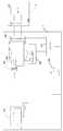
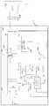
도 1a는 본 발명의 일 실시예에 따른 플라이 백 스위치 전원을 사용하는 단말기용 충전 시스템의 블록도이고;
도 1b는 본 발명의 일 실시예에 따른 포워드 스위치 전원을 사용하는 단말기용 충전 시스템의 블록도이며;
도 1c는 본 발명의 일 실시예에 따른 푸시폴 스위치 전원을 사용하는 단말기용 충전 시스템의 블록도이고;
도 1d는 본 발명의 일 실시예에 따른 반 브리지 스위치 전원을 사용하는 단말기용 충전 시스템의 블록도이며;
도 1e는 본 발명의 일 실시예에 따른 풀 브리지 스위치 전원을 사용하는 단말기용 충전 시스템의 블록도이고;
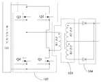
도 2a는 본 발명의 실시예에 따른 단말기용 충전 시스템의 블록도이며;
도 2b는 본 발명의 실시예에 따른 단말기용 충전 시스템의 블록도이고;
도 3은 본 발명의 일 실시예에 따른 전원 어댑터로부터 배터리로 출력되는 충전 전압 파형의 설명도이며;
도 4는 본 발명의 일 실시예에 따른 전원 어댑터로부터 배터리로 출력되는 충전 전류 파형의 설명도이고;
도 5는 본 발명의 일 실시예에 따라 스위치 유닛으로 출력되는 제어 신호의 설명도이며;
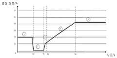
도 6은 본 발명의 일 실시예에 따른 고속 충전 과정의 설명도이고;
도 7a은 본 발명의 일 실시예에 따른 단말기용 충전 시스템의 블록도이며;
도 7b는 본 발명의 일 실시예에 따른 LC 필터 회로를 갖는 전원 어댑터의 블록도이고;
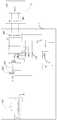
도 8은 본 발명의 다른 실시예에 따른 단말기용 충전 시스템의 블록도이며;
도 9는 본 발명의 또 다른 실시예에 따른 단말기용 충전 시스템의 블록도이고;
도 10은 본 발명의 또 하나의 실시예에 따른 단말기용 충전 시스템의 블록도이며;
도 11은 본 발명의 일 실시예에 따른 샘플링 유닛의 블록도이고;
도 12은 본 발명의 또 다른 하나의 실시예에 따른 단말기용 충전 시스템의 블록도이며;
도 13은 본 발명의 일 실시예에 따른 단말기의 블록도이고;
도 14은 본 발명의 다른 실시예에 따른 단말기의 블록도이며; 및
도 15는 본 발명의 실시예에 따른 단말기용 충전 방법의 흐름도이고;
도 16a와 도 16b는 본 발명의 실시예에 따른 맥동 파형의 설명도이다.1A is a block diagram of a charging system for a terminal using a flyback switch power supply according to an embodiment of the present invention;
1B is a block diagram of a charging system for a terminal using a forward switch power supply according to an embodiment of the present invention;
1C is a block diagram of a charging system for a terminal using a push-pole switch power supply according to an embodiment of the present invention;
1D is a block diagram of a charging system for a terminal using a half-bridge switch power supply according to an embodiment of the present invention;
1E is a block diagram of a charging system for a terminal using a full bridge switch power supply according to an embodiment of the present invention;
2A is a block diagram of a charging system for a terminal according to an embodiment of the present invention;
2B is a block diagram of a charging system for a terminal according to an embodiment of the present invention;
3 is an explanatory diagram of a charging voltage waveform output from a power adapter to a battery according to an embodiment of the present invention;
4 is an explanatory diagram of a charging current waveform output from a power adapter to a battery according to an embodiment of the present invention;
5 is an explanatory diagram of a control signal output to a switch unit according to an embodiment of the present invention;
6 is an explanatory diagram of a fast charging process according to an embodiment of the present invention;
7A is a block diagram of a charging system for a terminal according to an embodiment of the present invention;
7B is a block diagram of a power adapter having an LC filter circuit according to an embodiment of the present invention;
8 is a block diagram of a charging system for a terminal according to another embodiment of the present invention;
9 is a block diagram of a charging system for a terminal according to another embodiment of the present invention;
10 is a block diagram of a charging system for a terminal according to another embodiment of the present invention;
11 is a block diagram of a sampling unit according to an embodiment of the present invention;
12 is a block diagram of a charging system for a terminal according to another embodiment of the present invention;
13 is a block diagram of a terminal according to an embodiment of the present invention;
14 is a block diagram of a terminal according to another embodiment of the present invention; And
15 is a flowchart of a charging method for a terminal according to an embodiment of the present invention;
16A and 16B are explanatory diagrams of pulsation waveforms according to an embodiment of the present invention.
이하, 본 발명의 실시예를 상세히 설명하도록 하며, 상기 실시예는 첨부된 도면을 통해 도시되며, 처음부터 끝까지 동일하거나 유시한 부호는 동일하거나 유사한 기능을 갖는 구성 요소를 나타낸다. 이하 첨부된 도면을 참조하여 설명되는 실시예는 본 발명을 설명하기 위한 것이며 본 발명을 제한하려고 한 것은 아니다.Hereinafter, embodiments of the present invention will be described in detail, and the embodiments are illustrated through the accompanying drawings, and the same or similar reference numerals denote components having the same or similar functions. Embodiments described below with reference to the accompanying drawings are for explaining the present invention and are not intended to limit the present invention.
본 발명의 실시예에 의해 제기된 단말기용 충전기 시스템, 충전 방법, 및 전원 어댑터를 설명하기 전에, 먼저 관련 기술 중에 단말기 등 충전 대기 설비를 충전시키는 전원 어댑터를 설명하고자 한다. 이하 "관련 어댑터"로 지칭한다.Before describing the charger system, charging method, and power adapter for a terminal proposed by an embodiment of the present invention, first, a power adapter for charging a charging standby facility such as a terminal will be described. Hereinafter referred to as "related adapter".
관련 어댑터가 정전압 모드로 작동 시 출력되는 전압은 기본적으로 5V, 9V, 12V 또는 20V와 같이 일정하다.When the relevant adapter is operated in constant voltage mode, the output voltage is basically constant such as 5V, 9V, 12V or 20V.
관련 어댑터에서 출력되는 전압은 배터리 양단에 직접 로딩하기에는 적합하지 않고, 충전 대기 설비(예: 단말기) 내의 배터리가 소정의 충전 전압 및/또는 충전 전류를 얻기 위해서는 먼저 충전 대기 설비(예: 단말기) 내의 변환 회로에 의해 변환될 필요가 있다. 상기 충전 전류는 직류 전류일 수 있다.The voltage output from the relevant adapter is not suitable for direct loading across the battery, and in order for the battery in the charging standby facility (eg, terminal) to obtain a predetermined charging voltage and/or charging current, first in the charging standby facility (eg, terminal). It needs to be converted by a conversion circuit. The charging current may be a direct current.
배터리가 소정의 충전 전압 및/또는 충전 전류의 요구를 충족시키기 위해 변환 회로는 관련 어댑터에서 출력되는 전압을 변환시키는 데에 사용된다.A conversion circuit is used to convert the voltage output from the associated adapter so that the battery meets the requirements of a predetermined charging voltage and/or charging current.
하나의 예시로서, 해당 변환 회로는 충전 관리 모듈일 수 있으며, 예를 들어, 단말기 중의 충전 IC가 있는데, 이는 배터리의 충전 과정에서 배터리의 충전 전압 및/또는 충전 전류를 관리하는 데에 사용된다. 해당 변환 회로는 배터리의 충전 전압 및/또는 충전 전류에 대한 관리를 실현하기 위해 전압 피드백 모듈의 기능, 및/또는 전류 피드백 모듈의 기능을 갖는다.As an example, the conversion circuit may be a charge management module. For example, there is a charging IC in a terminal, which is used to manage the charging voltage and/or charging current of the battery during the charging process of the battery. The conversion circuit has a function of a voltage feedback module and/or a function of a current feedback module to realize management of the charging voltage and/or charging current of the battery.
예를 들어, 배터리의 충전과정은 트리클 충전 단계, 정전류 충전 단계 및 정 전압 충전 단계 중에 적어도 하나를 포함할 수 있다. 트리클 충전 단계에서, 변환 회로는 트리클 충전 단계에서 배터리에 들어가는 전류가 배터리가 소정의 충전 전류 크기(예컨대, 제1 충전 전류)를 충족시키기 위해 전류 피드백 루프를 이용할 수 있다. 정전류 충전 단계에서 변환 회로는 전류 피드백 루프를 이용할 수 있어 정전류 충전 단계에서 배터리에 들어가는 전류가 배터리가 소정의 충전 전류 크기(예컨대, 제2 충전 전류, 해당 제2 충전 전류는 제1 충전 전류보다 클 수 있음)를 충족시키도록 한다. 정전압 충전 단계에서 변환 회로는 전압 피드백 루프를 사용할 수 있어 정전압 충전 단계에서 배터리 양단에 로딩된 전압이 배터리가 소정의 충전 전압 크기를 충족시키도록 한다.For example, the charging process of the battery may include at least one of a trickle charging step, a constant current charging step, and a constant voltage charging step. In the trickle charging step, the conversion circuit may use a current feedback loop so that the current entering the battery in the trickle charging step allows the battery to meet a predetermined charging current level (eg, a first charging current). In the constant current charging step, the conversion circuit can use a current feedback loop, so that the current entering the battery in the constant current charging step is a predetermined amount of charging current of the battery (e.g., the second charging current, the corresponding second charging current is greater than the first charging current). Can meet). In the constant voltage charging step, the conversion circuit may use a voltage feedback loop so that the voltage loaded across the battery in the constant voltage charging step allows the battery to meet a predetermined charging voltage level.
하나의 예시로서, 관련 어댑터에서 출력되는 전압이 배터리가 소정의 충전 전압보다 클 경우, 변환 회로는 관련 어댑터에서 출력되는 전압에 대한 강압 전환 처리 시에 사용될 수 있어, 강압 전환 후의 충전 전압이 배터리가 소정의 충전 전압 요구를 충족시키도록 한다. 또 하나의 예시로서, 관련 어댑터에서 출력되는 전압이 배터리가 소정의 충전 전압보다 작을 경우, 변환 회로는 관련 어댑터의 전압을 승압 전환 처리 시에 사용될 수 있어, 승압 전환 후의 충전 전압이 배터리가 소정의 충전 전압 요구를 충족시키도록 한다.As an example, when the voltage output from the related adapter is greater than the predetermined charging voltage of the battery, the conversion circuit can be used in the step-down conversion process for the voltage output from the related adapter, so that the charging voltage after the step-down conversion is To meet the predetermined charging voltage requirements. As another example, when the voltage output from the related adapter is less than the predetermined charging voltage of the battery, the conversion circuit can be used in the step-up conversion process to the voltage of the related adapter, so that the charging voltage after the step-up conversion is To meet the charging voltage requirements.
또 하나의 예시로서, 관련 어댑터에서 5V 정전압을 출력하는 것을 예로 들면, 배터리가 단일 셀(리튬 배터리 셀일 경우, 단일 셀의 충전 차단 전압은 4.2V임)일 경우, 변환 회로(예컨대, Buck 강압 회로)는 관련 어댑터에서 출력되는 전압을 강압 전환 처리할 수 있어 강압 처리 후의 충전 전압이 배터리가 소정의 충전 전압 요구를 충족시키도록 한다.As another example, for example, when the battery is a single cell (in the case of a lithium battery cell, the charging cutoff voltage of the single cell is 4.2V), a conversion circuit (e.g., a Buck step-down circuit) ) Can perform step-down conversion processing of the voltage output from the relevant adapter so that the charging voltage after the step-down processing allows the battery to meet a predetermined charging voltage requirement.
또 하나의 예시로서, 관련 어댑터에서 5V 정전압을 출력하는 것을 예로 들면, 관련 어댑터에 의해 두 개 이상의 단일 셀이 직렬로 연결된 배터리(리튬 배터리 셀일 경우, 단일 셀의 충전 차단 전압은 4.2V임)가 충전될 경우, 변환 회로(예컨대, Boost 승압 회로)는 관련 어댑터에서 출력되는 전압을 승압 전환 처리를 할 수 있어, 승압 후의 충전 전압이 배터리가 소정의 충전 전압 요구를 충족시키도록 한다.As another example, when outputting a 5V constant voltage from a related adapter, for example, a battery in which two or more single cells are connected in series by a related adapter (in the case of a lithium battery cell, the charge cutoff voltage of a single cell is 4.2V). When charged, the conversion circuit (e.g., the Boost booster circuit) can perform step-up conversion processing of the voltage output from the associated adapter, so that the charging voltage after boosting allows the battery to meet a predetermined charging voltage requirement.
변환 회로는 회로 전환 효율 저하로 인해 미 전환된 일부 전기 에너지를 열량으로 손실하게 하며, 이 부분의 열량은 충전 대기 설비(예: 단말기) 내부에 축적되지만 충전 대기 설비(예: 단말기)의 설계 공간 및 산열 공간이 모두 협소(예컨대, 사용자가 사용하는 이동 단말기의 물리적 크기가 갈수록 얇아지고 있고, 또한 이동 단말기의 성능을 향상하기 위해 이동 단말기 내부에 다수의 전자 부품이 조밀하게 배치되어 있음)하기에 이는 변환 회로의 설계 난이도를 향상시킬 뿐만 아니라 충전 대기 설비(예: 단말기)내부에 축적된 열량도 적시 소산되지 못하게 하고, 충전 대기 설비(예: 단말기)의 이상을 유발한다.The conversion circuit causes some unconverted electrical energy to be lost as heat due to the decrease in circuit conversion efficiency, and the heat amount of this part is accumulated inside the charging standby facility (eg terminal), but the design space of the charging standby facility (eg terminal) And the heat distributing space is all narrow (for example, the physical size of the mobile terminal used by the user is getting thinner, and a number of electronic components are densely arranged inside the mobile terminal to improve the performance of the mobile terminal). This not only improves the design difficulty of the conversion circuit, but also prevents the heat accumulated in the charging standby facility (eg, terminal) from dissipating in a timely manner, and causes an abnormality in the charging standby facility (eg, terminal).
예를 들어, 변환 회로에 축적된 열량으로 인해 변환 회로 부근에 있는 전자 부품에 열적 간섭이 일어나 전자 부품의 비정상적인 작동을 야기할 수 있으며; 및/또는 예를 들어, 변환 회로에 축적된 열량으로 인해 변환 회로 및 부근에 있는 전자 부품의 사용 수명을 단축시킬 수 있고; 및/또는 변환 회로에 축적된 열량으로 인해 배터리에 열적 간섭이 일어나 배터리의 비정상적인 충전과 방전을 야기할 수 있으며; 및/또는 변환 회로에 축적된 열량으로 인해 충전 대기 설비(예: 단말기)의 온도가 상승되어 충전 중 사용자의 사용 경험에 영향을 끼칠 수 있고; 및/또는 예를 들어, 변환 회로에 축적된 열량으로 인해 변환 회로 자체의 단락이 발생해 관련 어댑터에서 출력되는 전압이 배터리 양단에 직접 로딩되어 비정상적인 충전을 일으키며, 배터리가 장기간 과전압 상태에 처하면, 심지어 배터리의 폭발을 일으킬 수 있어 잠재적 안전 위험 요소를 갖고 있다.For example, due to the amount of heat accumulated in the conversion circuit, thermal interference may occur in an electronic component in the vicinity of the conversion circuit, causing abnormal operation of the electronic component; And/or it is possible to shorten the service life of the conversion circuit and nearby electronic components due to, for example, the amount of heat accumulated in the conversion circuit; And/or due to the amount of heat accumulated in the conversion circuit, thermal interference may occur in the battery, causing abnormal charging and discharging of the battery; And/or due to the amount of heat accumulated in the conversion circuit, the temperature of the charging standby facility (eg, a terminal) may increase, thereby affecting the user's experience during charging; And/or, for example, due to the amount of heat accumulated in the conversion circuit, a short circuit occurs in the conversion circuit itself, and the voltage output from the relevant adapter is directly loaded across the battery, causing abnormal charging, and if the battery is in an overvoltage condition for a long time, even It has a potential safety hazard as it can cause the battery to explode.
그러나 본 발명에서 제공되는 전원 어댑터는 배터리의 상태 정보를 얻을 수 있으며, 배터리의 상태 정보는 적어도 배터리의 현재 전기량 정보 및/또는 전압 정보를 포함하고 있으며, 해당 전원 어댑터는 얻은 배터리의 상태 정보에 따라 전원 어댑터 자체의 출력 전압을 조절하여 배터리가 소정의 충전 전압 및/또는 충전 전류의 요구를 충족시키도록 하고, 전원 어댑터가 조절 후에 출력되는 전압은 배터리 양단에 직접 로딩되어 배터리를 충전할 수 있다(이하 "직접 충전"으로 함). 일부 실시예에서 해당 전원 어댑터에서 맥동 파형의 전압이 출력된다.However, the power adapter provided in the present invention can obtain the status information of the battery, and the status information of the battery includes at least current electricity quantity information and/or voltage information of the battery, and the power adapter is based on the obtained battery status information. The output voltage of the power adapter itself is adjusted so that the battery meets the requirements of a predetermined charging voltage and/or charging current, and the voltage output after the power adapter is adjusted can be loaded directly across the battery to charge the battery ( Hereinafter referred to as "direct charging"). In some embodiments, a voltage of a pulsating waveform is output from the power adapter.
해당 전원 어댑터는 전압 피드백 모듈의 기능과 전류 피드백 모듈의 기능을 갖고 있어 배터리의 충전 전압 및/또는 충전 전류에 대한 관리를 실현하도록 한다.The power adapter has a function of a voltage feedback module and a function of a current feedback module to realize management of the charging voltage and/or charging current of the battery.
해당 전원 어댑터가 획득한 배터리의 상태 정보에 따라 자체의 출력 전압을 조절하는 것은, 해당 전원 어댑터가 배터리의 상태 정보를 실시간으로 획득할 수 있고, 매번 획득한 배터리의 실시간 상태 정보에 따라 전원 어댑터 자차의 출력 전압을 조절하여 배터리가 소정의 충전 전압 및/또는 충전 전류를 충족시키도록 하는 것을 의미할 수 있다.Adjusting its own output voltage according to the battery status information obtained by the power adapter allows the power adapter to acquire battery status information in real time, and the power adapter itself according to the real-time status information of the battery acquired each time. It may mean that the battery meets a predetermined charging voltage and/or charging current by adjusting the output voltage of.
해당 전원 어댑터가 실시간으로 획득한 배터리의 상태 정보에 따라 자체의 출력 전압을 조절하는 것은, 충전 중에 배터리의 충전 전압이 계속 상승함에 따라 전원 어댑터가 충전 중에 상이한 시각의 배터리의 현재 상태 정보를 획득할 수 있고, 배터리의 현재 상태 정보에 따라 전원 어댑터 자체의 출력 전압을 실시간으로 조절하여 배터리가 소정의 충전 전압 및/또는 충전 전류의 요구를 충족시키도록 하고, 전원 어댑터에서 출력되는 전압은 배터리 양단에 직접 로딩되어 배터리를 충전할 수 있다.When the power adapter adjusts its own output voltage according to the status information of the battery acquired in real time, the power adapter can acquire current status information of the battery at different times during charging as the charging voltage of the battery continues to rise. The output voltage of the power adapter itself is adjusted in real time according to the current state information of the battery so that the battery meets the requirements of a predetermined charging voltage and/or charging current, and the voltage output from the power adapter is applied across the battery. It can be loaded directly to charge the battery.
예를 들어, 배터리의 충전 과정은 트리클 충전 단계, 정전류 충전 단계 및 정 전압 충전 단계 중의 적어도 하나를 포함할 수 있다. 트리클 충전 단계에서, 전원 어댑터는 트리클 충전 단계에서 제1 충전 전류를 출력하여 배터리를 충전시켜 배터리가 소정의 충전 전류의 요구를 충족시킬 수 있다(제1 충전 전류는 맥동 파형의 전류일 수 있음). 정전류 충전 단계에서 전원 어댑터는 전류 피드백 루프를 이용할 수 있어 정전류 충전 단계에서 전원 어댑터에 의해 출력되어 배터리에 들어가는 전류가 배터리가 소정의 충전 전류 크기를 충족시킨다(예컨대, 맥동 파형의 전류인 제2 충전전류, 해당 제2 충전 전류는 제1 충전 전류보다 클 수 있으며, 정전류 단계의 맥동 파형의 전류 피크가 트리클 충전 단계의 맥동 파형의 전류 피크보다 클 수 있다). 정전압 단계에서 전원 어댑터는 전압 피드백 루프를 사용할 수 있어 정전압 충전 단계에서 전원 어댑터에서 충전 대기 설비(예: 단말기)로 출력되는 전압(즉 맥동 파형의 전압)이 일정하게 유지하도록 한다.For example, the charging process of the battery may include at least one of a trickle charging step, a constant current charging step, and a constant voltage charging step. In the trickle charging step, the power adapter may charge the battery by outputting the first charging current in the trickle charging step, so that the battery can meet the demand of a predetermined charging current (the first charging current may be a current of a pulsating waveform) . In the constant current charging step, the power adapter can use a current feedback loop, so that the current output by the power adapter and entering the battery in the constant current charging step meets a predetermined charge current level (e.g., a second charge that is a pulsating current) The current and the corresponding second charging current may be greater than the first charging current, and the current peak of the pulsating waveform in the constant current step may be greater than the current peak of the pulsating waveform in the trickle charging step). In the constant voltage phase, the power adapter can use a voltage feedback loop, so that the voltage (that is, the voltage of the pulsating waveform) output from the power adapter to the charging standby facility (eg, terminal) in the constant voltage charging phase remains constant.
예를 들어, 본 발명의 실시예에서 언급된 전원 어댑터는 주로 충전 대기 설비(예: 단말기) 내부 전류의 정전류 충전단계를 제어하는 데에 사용될 수 있다. 다른 실시예에서, 충전 대기 설비(예: 단말기) 내부 전류의 트리클 충전 단계와 정전압 충전 단계의 제어 기능은 본 발명의 실시예에서 언급된 저원 어댑터와 충전 대기 설비(예: 단말기)내부 별도의 충전 칩의 협조에 의해 구현될 수 있으며; 정전류 충전 단계에 비해, 배터리는 트리클 충전단계 및 정전압 단계에서 더 작은 충전 전력을 허용하고, 충전 대기 설비(예: 단말기)의 내부 충전 칩의 효율 전환 손실 및 열량 축적은 허용될 수 있다. 설명해야 할 것은, 본 발명의 실시예에서 언급된 정전류 충전단계와 정전류 단계는 전원 어댑터에서 출력되는 전류를 제어하는 충전 모드를 지칭할 수 있으며, 전원 어댑터에서 출력되는 전류가 완전히 일정하게 유지를 요구하지는 않고, 예를 들어, 일반적으로 전원 어댑터에서 출력되는 맥동 파형의 전류 피크 또는 평균값이 그대로 유지되거나 어느 시간대에 그대로 유지되는 것을 가리킬 수 있다. 예를 들어, 실제로 정전류 충전 단계에서는 전원 어댑터가 일반적으로 다단식 정전류 충전을 이용한다.For example, the power adapter mentioned in the embodiment of the present invention can be mainly used to control the constant current charging step of the internal current of the charging standby facility (eg, terminal). In another embodiment, the control function of the trickle charging step and the constant voltage charging step of the internal current of the charging standby facility (eg, a terminal) is a separate charging inside the low power adapter and the charging standby facility (eg, terminal) mentioned in the embodiment of the present invention. Can be implemented by the cooperation of the chip; Compared to the constant current charging step, the battery allows a smaller charging power in the trickle charging step and the constant voltage step, and the efficiency conversion loss and heat accumulation of the internal charging chip of the charging standby facility (eg, terminal) may be allowed. It should be explained that the constant current charging step and the constant current step mentioned in the embodiments of the present invention may refer to a charging mode for controlling the current output from the power adapter, and it is required to keep the current output from the power adapter completely constant. Without doing so, for example, it may indicate that the current peak or average value of the pulsating waveform output from the power adapter is maintained as it is or is maintained in a certain time period. In practice, for example, in the constant current charging phase, the power adapter generally uses multistage constant current charging.
다단식 정전류 충전(Multi-stage constant current charging)은 N 개의 정전류 단계(N은 2 이상의 정수)를 가질 수 있으며, 다단식 정전류 충전은 소정의 충전 전류로 제1 단계의 충전을 시작하고, 상기 다단식 정전류 충전의 N개의 정전류 단계는 제1 단계로부터 제(N-1) 단계까지 순차적으로 수행되며, 정전류 단계 중 이전 정전류 단계에서 다음 정전류 단계로 이동 후, 맥동 파형의 전류 피크 또는 평균값이 작아질 수 있고; 배터리 전압이 충전 전압 종단 전압 문턱 값에 도달 시 정전류 단계 중의 이전 정전류 단계가 다음 정전류 단계로 이동된다. 인접한 2개의 정전류 단계 사이의 전류 전환 과정은 점차 변화일 수 있고, 또는 스텝식의 점프 변화일 수도 있다.Multi-stage constant current charging may have N constant current stages (N is an integer of 2 or more), and multi-stage constant current charging starts charging of the first stage with a predetermined charging current, and the multi-stage constant current charging The N constant current steps of are sequentially performed from the first step to the (N-1)th step, and after moving from the previous constant current step to the next constant current step among the constant current steps, the current peak or average value of the pulsating waveform may decrease; When the battery voltage reaches the charging voltage termination voltage threshold, the previous constant current step in the constant current step moves to the next constant current step. The current conversion process between adjacent two constant current steps may be a gradual change, or may be a stepwise jump change.
또한 설명해야 할 것은 본 발명의 실시예에서 사용된 "단말기"는 유선 선로를 통해 접속(예를 들어, 공중교환전화망(PSTN), 디지털 가입자 회선(DSL), 디지털 케이블, 직접적인 케이블 접속, 및/또는 다른 데이터 접속/네트워크를 통함) 및/또는 (예를 들어, 셀룰러 네트워크, 무선 랜(WLAN), DVB-H 네트워크와 같은 디지털 TV 네트워크, 위성 네트워크, AM-FM 방송 송신기 및/또는 다른 통신 단말기를 위한)무선 인터페이스를 통해 통신 신호를 수신/발신할 수 있도록 설정된 장치를 포함할 수 있지만 이에 한정되지는 않는다. 무선 인터페이스를 통해 통신하도록 설정된 단말기는 "무선 통신 단말기", "무선 단말기" 및/또는 "이동 단말기"로 지칭할 수 있다. 이동 단말기의 예시로는 위성 또는 셀룰러 전화; 셀룰러 무선 전화와 데이터 처리, 팩스 및 데이터 통신 능력을 결합할 수 있는 개인 통신 시스템(PCS)단말기; 무선 전화, 무선 호출기, 인터넷/인트라넷 접속, 웹 브라우저, 일기 및/또는 GPS수신기를 포함하는 PDA; 및 일반적인 랩탑 및/또는 팜탑 수신기 또는 무선 전화 수신기의 기타 전자 장치를 포함하되 이에 한정되지는 않는다.It should also be explained that the "terminal" used in the embodiment of the present invention is connected through a wired line (for example, a public switched telephone network (PSTN), a digital subscriber line (DSL), a digital cable, a direct cable connection, and/or Or via other data access/network) and/or (e.g., cellular networks, wireless LANs (WLANs), digital TV networks such as DVB-H networks, satellite networks, AM-FM broadcast transmitters and/or other communication terminals. For), a device configured to receive/transmit a communication signal through a wireless interface may be included, but is not limited thereto. A terminal configured to communicate through a wireless interface may be referred to as a "wireless communication terminal", a "wireless terminal" and/or a "mobile terminal". Examples of mobile terminals include satellite or cellular telephones; Personal Communication System (PCS) terminals capable of combining cellular wireless telephones with data processing, fax and data communication capabilities; PDAs including wireless telephones, wireless pagers, Internet/intranet connections, web browsers, diary and/or GPS receivers; And other electronic devices of a general laptop and/or palmtop receiver or a wireless telephone receiver, but is not limited thereto.
또한, 본 발명의 실시예에서, 전원 어댑터에서 출력되는 맥동 파형의 전압이 단말기의 배터리에 직접 로딩된 후 배터리를 충전할 경우, 충전 전류는 만두형태 웨이브와 같은 맥동 파로 나타나고, 충전 전류는 간헐적으로 배터리를 충전시키는 것으로 이해될 수 있고, 해당 충전 전류의 주기는 입력된 교류 전류(예컨대, 교류 전류 망의 주파수)에 따라 변화되고, 예를 들어, 충전 전류의 주기에 대응하는 주파수는 전력망 주파수의 정수 배 또는 역수 배이다. 또한, 충전 저류는 간헐적으로 배터리를 충전시킬 경우, 해당 충전 전류에 대응하는 전류 파형은 전력망과 동기화된 하나 또는 한 그룹의 펄스로 구성될 수 있다.In addition, in an embodiment of the present invention, when charging the battery after the voltage of the pulsating waveform output from the power adapter is directly loaded into the battery of the terminal, the charging current appears as a pulsating wave such as a dumpling wave, and the charging current is intermittently It can be understood as charging the battery, and the period of the corresponding charging current is changed according to the input AC current (eg, the frequency of the AC current network), and for example, the frequency corresponding to the period of the charging current is the frequency of the power grid. It is an integer multiple or an reciprocal multiple. In addition, when the charge storage intermittently charges the battery, a current waveform corresponding to the corresponding charging current may be composed of one or a group of pulses synchronized with the power grid.
하나의 예시로서, 본 발명의 실시예에서 배터리가 충전 과정 중(예를 들어, 트리클 충전 단계, 정전류 충전 단계 및 정 전압 충전 단계 중 적어도 하나)에 어댑터에서 출력되는 맥동 직류 전류(방향은 변하지 않고, 진폭 크기는 시간에 따라 변함), 교류 전류(방향과 진폭 크기 모두 시간에 따라 변함), 직류 전류(즉 일정한 직류이며, 진폭 크기와 방향은 모두 시간에 따라 변하지 않음)를 수용할 수 있다.As an example, in the embodiment of the present invention, the pulsating DC current output from the adapter during the charging process of the battery (for example, at least one of a trickle charging step, a constant current charging step, and a constant voltage charging step) (direction does not change) , Amplitude magnitude changes over time), AC current (both direction and amplitude magnitude change over time), DC current (that is, constant direct current, and both amplitude magnitude and direction do not change over time) can be accommodated.
관련 어댑터의 2차 측에는 여러 개의 액상 알루미늄 전해 커패시터가 포함되어 있으며 다음과 같은 단점을 갖고 있다. 첫째, 액상 알루미늄 전해 커패시터의 부피가 비교적 크므로 어댑터의 부피도 커지게 된다. 둘째, 액상 알루미늄 전해 커패시터의 형상은 일반적으로 원기동체이고 이는 회로 기판의 면적을 많이 차지하므로 어댑터 내부의 회로 기판의 전체 배선을 어렵게 한다. 셋째, 액상 알루미늄 전해 커패시터의 사용 수명이 제한됨으로 어댑터의 사용 수명도 제한된다. 넷째, 액상 알루미늄 전해 커패시터에 버스터 현상이 일어날 수 있어, 버스터 후 남게 된 전해액은 전도체이므로 어댑터에 잠재적 안전 위험 요소를 갖게 된다.The secondary side of the associated adapter contains several liquid aluminum electrolytic capacitors and has the following disadvantages: First, since the volume of the liquid aluminum electrolytic capacitor is relatively large, the volume of the adapter is also increased. Second, the shape of the liquid aluminum electrolytic capacitor is generally a prime mover, which occupies a large area of the circuit board, making it difficult to wire the entire circuit board inside the adapter. Third, the service life of the adapter is also limited due to the limited service life of the liquid aluminum electrolytic capacitor. Fourth, a bursting phenomenon may occur in the liquid aluminum electrolytic capacitor, and since the electrolyte remaining after the bursting is a conductor, there is a potential safety hazard to the adapter.
상기 문제 중의 적어도 하나를 해결하기 위해, 도 2A에 도시된 바와 같이, 본 발명의 실시예에서 전원 어댑터(1)와 단말기(2)를 포함하는 단말기용 충전 시스템을 제공하고 있다.In order to solve at least one of the above problems, as shown in Fig. 2A, in the embodiment of the present invention, a charging system for a terminal including a
전원 어댑터(1)는 제1 정류 유닛(101)과 제2 정류 유닛(104)을 포함한다.The
제1 정류 유닛(101)은 충전 과정 중에 입력된 교류 전류를 정류하여 제1 맥동 파형의 전압을 출력하는 데에 사용된다.The
제2 정류 유닛(104)은 1차 측에서 2차 측으로 결합된 전압을 정류하는 데에 사용된다. 제2 정류 유닛(104)의 정류 후에 출력되는 전류의 파형이 상기 제1 맥동 파형의 주기와 같고, 또는 제2 정류 유닛(104)의 정류 후에 출력되는 전류의 파형의 포락이 상기 제1 맥동 파형의 주기와 같다.The
단말기(2)는 전원 어댑터의 출력 전압을 기준으로 하여 단말기(2) 내의 배터리(202)를 충전시킨다.The terminal 2 charges the
본 발명의 실시예에 따른 전원 어댑터에는 1차 측에 있는 정류를 위한 액상 알루미늄 전해 커패시터를 제거하여 제1 정류 유닛이 맥동 파형의 전압을 직접 출력할 수 있도록 하며 따라서 어댑터의 부피도 줄이게 된다. 또한 1차 측에 있는 액상 알루미늄 전해 커패시터의 사용 수명이 짧고 버스트하기 쉬움으로 1차 측에 잇는 액상 알루미늄 전해 커패시터를 제거함으로써 어댑터의 사용 수명과 안전성을 크게 향상시킬 수 있다.In the power adapter according to the embodiment of the present invention, the liquid aluminum electrolytic capacitor for rectification on the primary side is removed so that the first rectification unit can directly output the voltage of the pulsating waveform, and thus the volume of the adapter is reduced. In addition, since the liquid aluminum electrolytic capacitor on the primary side has a short service life and is easy to burst, it is possible to greatly improve the service life and safety of the adapter by removing the liquid aluminum electrolytic capacitor on the primary side.
제2 정류 유닛(104)의 정류 후에 출력되는 전류의 파형이 상기 제1 맥동 파형의 주기와 같다는 것은, 제2 정류 유닛(104)의 정류 후에 출력되는 전류의 파형이 제1 맥동 파형과 동기화하고 있는 것을 의미할 수 있다.That the waveform of the current output after the rectification of the
제2 정류 유닛(104)의 정류 후에 출력되는 전류의 파형의 포락이 상기 제1 맥동 파형의 주기와 같다는 것은, 제2 정류 유닛(104)의 정류 후에 출력되는 전류의 파형의 포락이 제1 맥동 파형과 동기화하고 있는 것을 의미할 수 있다.That the envelope of the waveform of the current output after the rectification of the
제2 정류 유닛(104)의 정류 후에 출력되는 전류의 파형 포락은 완전한 맥동 파형일 수 있고, 또한 클리핑 처리 후에 얻게 된 맥동 파형(T자형과 유사하며, 구체적으로는 도 16b 참조)일 수도 있는 것으로 이해되어야 한다.The waveform envelope of the current output after the rectification of the
일부 실시예에서 제2 정류 유닛(104)에서 출력되는 전류는 어댑터(1)의 출력 전류로 하여 직접 출력될 수 있다. 다른 일부 실시예에서 제2 정류 유닛(104)에서 출력되는 전류 파형 또는 전류 파형의 포락에 대해 다양한 파형 변환을 실행하고 파형 변환 후에 얻게 된 전류를 어댑터(1)의 출력 전류로 할 수 있다. 예를 들어, 제2 정류 유닛(104)에서 출력되는 전압 파형/전류 파형을 방형파, 삼각형파 등 파형으로 변환시킨 후 방형파인 파형의 전류 또는 삼각형파인 파형의 전류를 출력할 수 있다. 전류 파형의 변경 방식은 여러 가지가 있고, 예를 들어, 제2 정류 유닛(104) 뒤에 스위치, 커패시터 등 소자를 배치할 수 있어 제2 정류 유닛(104)에서 출력되는 전류 파형의 형상을 변경하도록 한다.In some embodiments, the current output from the
마찬가지로 제2 정류 유닛(104)에서 출력되는 전압이 직접 어댑터(1)의 출력 전압으로 할 수 있고, 또한 제2 정류 유닛(104)에서 출력되는 전압 파형 또는 전압 파형의 포락에 대해 다양한 변환을 실행하고 파형 변환 후에 얻게 된 전압을 어댑터(1)의 출력 전압으로 할 수 있다. 이하, 주로 어댑터(1)에서 출력되는 제3 맥동 파형의 전압을 예로 하여 설명하도록 하지만 본 발명의 실시예는 이에 한정되지는 않는다.Similarly, the voltage output from the
본 발명의 실시예에서 언급된 하나 또는 여러 개의 맥동 파형의 전압은 비음의 맥동 파형(예컨대, 제1 맥동 파형)일 수 있고, 양음 교체 식의 맥동 파형(예컨대, 제2 맥동 파형)일 수도 있는 것으로 이해되어야 한다. 또한 본 발명의 실시예에서 언급된 하나 또는 여러 개의 파형은 구체적으로 거시적 또는 전체적인 추세로 봤을 때 맥동 형태로 나타나고 있는 것을 뜻할 수 있으며, 미시적으로 보면 맥동 파형은 연속적으로 또는 비연속적으로 변화될 수 있다. 예를 들어, 제2 맥동 파형의 전압과 제2 맥동 파형의 전압은 스위치 유닛(102)을 통해 초퍼 처리 후에 얻게 된 전압일 수 있고, 2차 필터링 처리하지 않을 경우, 미시적으로 보면 해당 제2 맥동 파형 또는 제3 맥동 파형은 다수의 작은 비연속적인 펄스 조합으로 구성될 수 있다. 그러나 전체적으로 보면 해당 전압의 파형은 여전히 맥동 형식의 파형이고, 따라서 본 발명의 실시예에서 전체적 또는 거시적인 측면으로 봤을 때 맥동으로 나타난 파형도 맥동 파형으로 한다. 즉 본 발명의 실시예에서 언급된 하나 또는 여러 개의 맥동 파형의 전압은 전압의 포락이 맥동 파형으로 나타나고 있다는 것을 의미할 수 있다. 또한, 본 발명의 하나 또는 여러 개의 맥동 파형은 완전한 맥동 파형일 수 있고, 그리고 클리핑 처리 후에 얻게 된 맥동 파형일 수도 있다. 예를 들어, 제3 맥동 파형의 전압의 피크는 도 16A에 도시된 완전한 맥동 파형일 수 있고, 도 16b에 도시된 클리핑 처리 후의 맥동 파형일 수 있다. 또한, 충전 과정 중에 배터리 양단의 전압이 맥동 파형의 전압에 대해 클램핑 효과를 갖고 있으며, 본 발명의 실시예의 하나 또는 여러 개의 맥동 파형은 클랭핑 후에 형성된 맥동 파형(구체적으로 도 3에 도시된 바와 같음)을 뜻할 수 있으며, 충전 과정 중에 제3 맥동 파형의 전압은 클랭핑 후의 맥동 파형일 수 있다.The voltage of one or more pulsating waveforms mentioned in the embodiments of the present invention may be a non-negative pulsating waveform (eg, a first pulsating waveform), or a positive-negative pulsating waveform (eg, a second pulsating waveform). It should be understood as. In addition, one or several waveforms mentioned in the embodiments of the present invention may specifically mean that they appear in a form of pulsation when viewed as a macroscopic or overall trend, and when viewed microscopically, the pulsating waveform may be continuously or discontinuously changed. . For example, the voltage of the second pulsating waveform and the voltage of the second pulsating waveform may be the voltage obtained after the chopper processing through the
이하, 도면을 참조하여 본 발명의 실시예에서 제기되는 단말기용 충전 시스템, 전원 어댑터, 단말기용 충전 방법을 설명하도록 한다.Hereinafter, a charging system for a terminal, a power adapter, and a charging method for a terminal proposed in an embodiment of the present invention will be described with reference to the drawings.
도 1a 내지 도 14에 도시된 바에 따르면, 본 발명의 실시예에서 제기되는 단말기용 충전 시스템은 전원 어댑터(1)와 단말기(2)를 포함한다.1A to 14, a charging system for a terminal proposed in an embodiment of the present invention includes a
도 2b에 도시된 바와 같이, 전원 어댑터(1)는 제1 정류 유닛(101), 스위치 유닛(102), 변압기(103), 제2 정류 유닛(104), 제1 충전 인터페이스(101), 샘플링 유닛(106)과 제어 유닛(107)을 포함한다. 제1 정류 유닛(101)은 입력된 교류 전류(도시 가정용 전기, 예: AC220V)를 정류하여 제1 맥동 파형의 전압(예: 만두 형태 웨이브 전압)을 출력하고, 여기서 도 1a에 도시된 바와 같이, 제1 정류 유닛은 4개의 다이오드로 구성된 풀 브리지 정류 회로일 수 있다. 스위치 유닛(102)은 제어 신호에 따라 제1 맥동 파형의 전압을 변조하는 데에 사용되고, 여기서여기서 스위치 유닛(102)은 MOS 트랜지스터로 구성될 수 있고, MOS 트랜지스터에 대한 PWM(Pulse Width Modulation, 펄스 폭 변조)제어로 만두 형태 웨이브 전압을 초퍼 변조한다. 변압기(103)는 변조된 상기 제1 맥동 파형의 전압에 따라 제2 맥동 파형의 전압을 출력하는 데에 사용되고, 제2 정류 유닛(104)은 상기 제2 맥동 파형의 전압에 따라 제3 파형 맥동의 전압을 출력하는 데에 사용되고, 여기서여기서, 제2 정류 유닛(104)은 다이오드 또는 MOS 트랜지스터로 구성될 수 있고, 2차적 동기 정류가 실현될 수 있으며, 따라서 제3 맥동 파형의 전압이 변조된 제1 맥동 파형과의 동기화를 유지한다., 설명되는 바와 같이, 제3 맥동 파형은 변조된 제1 맥동 파형과 동기화를 유지하는 것은, 구체적으로 제3 맥동 파형의 위상이 변조된 제1 파형의 위상과의 일치함을 유지하고, 제3 맥동 파형의 진폭이 변조된 제1 맥동 파형의 진폭 변동 추세와의 일치함을 유지하는 것을 의미한다. 제1 충전 인터페이스(105)는 제2 정류 유닛(104)과 연결되고, 샘플링 유닛(106)은 제2 정류 유닛(104)에서 출력되는 전압 및/또는 제2 전류를 샘플링하여 전압 샘플링 값 및 전류 샘플링 값을 획득하는 데에 사용되고, 제어 유닛(107)은 샘플링 유닛(106) 및 스위치 유닛(102)에 각각 연결되고, 제어 유닛(107)은 스위치 유닛(102)에 제어 신호를 출력하고, 전압 샘플링 값 및/또는 전류 샘플링 값에 따라 제어 신호의 듀티비를 조절하여 제2 정류 유닛(104)에서 출력되는 제3 맥동 파형의 전압이 충전 요구를 충족하도록 한다.2B, the
도 2b에 도시된 바와 같이, 단말기(2)는 제2 충전 인터페이스(201)와 배터리(202)를 포함하고, 제2 충전 인터페이스(201)가 배터리(202)와 연결되고, 여기서 제2 충전 인터페이스(201)가 제1 충전 인터페이스(105)와 연결되면 제2 충전 인터페이스(201)는 제3 맥동 파형의 전압을 배터리(202)에 로딩하게 하고, 배터리(202)를 위한 충전을 실현한다.2B, the
본 발명의 일 실시예에 따르면, 도 1a에 도시된 바와 같이, 전원 어댑터(1)는 플라이 백 스위치 전원을 사용할 수 있다. 구체적으로, 변압기(103)는 1차 권선과 2차 권선을 포함하고, 1차 권선의 한 단은 제1 정류 유닛(101)의 제1 출력 단과 연결되고, 제1 정류 유닛(101)의 제2 출력 단은 접지되며, 1차 권선의 다른 한 단은 스위치 유닛(102)과 연결되며(예를 들어, 해당 스위치 유닛(102)은 MOS 트랜지스터이고, 여기서는 1차 권선의 다른 한 단은 MOS 트랜지스터의 드레인과 연결됨을 의미함), 변압기(103)는 변조된 제1 맥동 파형의 전압에 따라 제2 맥동 파형의 전압을 출력하는 데에 사용된다.According to an embodiment of the present invention, as shown in Fig. 1A, the
여기서 변압기(103)는 고주파 변압기이고, 작동 주파수는 50KHz∼2MHz일 수 있고, 고주파 변압기는 제1 맥동 파형의 전압을 2차 측으로 결합시켜 2차 권선에 의해 출력된다. 본 발명의 실시예에서 고주파 변압기를 사용하며 저주파 변압기(저주파 변압기는 또한 전력 주파수 변압기로도 불리며, 주로 50Hz 또는 60Hz인 교류 전류와 같은 도시 가정용 전기의 주파수를 지칭하는 데에 사용됨)에 비해 작은 부피를 갖는 고주파 변압기의 특징을 이용해 전원 어댑터(1)의 소형화를 실현할 수 있다.Here, the
본 발명의 일 실시예에 따르면, 도 1b에 도시된 바와 같이, 상기 전원 어댑터(1)는 또한 포워드 스위치 전원을 사용할 수 있다. 구체적으로, 변압기(103)는 제1 권선, 제2 권선과 제3 권선을 포함하고, 제1 권선의 동명 단(homonymous end)은 역방향 다이오드를 통해 제1 정류 유닛(101)의 제2 출력 단과 연결되고, 제1 권선의 이명 단(synonym end)은 제2 권선의 동명 단과 연결된 후 제1 정류 유닛(101)의 제1 출력 단과 연결되며, 제2 권선의 이명 단은 스위치 유닛(102)과 연결되고, 제3 권선은 제2 정류 유닛(104)과 연결된다. 여기서 역방향 다이오드는 인버스 클리핑의 역할을 하고, 제1 권선에 의해 발생된 유도 전기력은 역방향 다이오드를 통해 역 전기력의 진폭 제한하고, 제한된 에너지를 제1 정류 유닛의 출력으로 반환시킬 수 있으며, 제1 정류 유닛의 출력을 위한 충전을 진행하며, 제1 권선에 흐르는 전류에 의해 발생한 자기장은 변압기의 코어의 자성을 없앨 수 있고, 변압기 코어의 자기장 강도를 초기 상태로 복귀시킨다. 변압기(103)는 변조된 제1 맥동 파형의 전압에 따라 제2 맥동 파형의 전압을 출력하는 데에 사용된다.According to an embodiment of the present invention, as shown in Fig. 1B, the
본 발명의 일 실시예에 따라 도 1c에 도시된 바와 같이, 상기 전원 어댑터(1)는 또한 푸시폴 스위치 전원을 사용할 수 있다. 구체적으로 상기 변압기는 제1 권선, 제2 권선, 제3 권선과 제4 권선을 포함하고, 상기 제1 권선의 동명 단은 상기 스위치 유닛과 연결되고, 상기 제1 권선의 이명 단은 상기 제2 권선의 동명 단과 연결된 후 상기 제1 정류 유닛의 제1 출력단과 연결되며, 상기 제2 권선의 이명 단은 상기 스위치 유닛과 연결되고, 상기 제3 권선의 이명 단은 상기 제4 권선의 동명 단과 연결되며, 상기 변압기는 변조된 상기 제1 맥동 파형의 전압에 따라 제2 맥동 파형의 전압을 출력하는 데에 사용된다.As shown in Fig. 1c according to an embodiment of the present invention, the
도 1c에 도시된 바와 같이, 스위치 유닛(102)은 제1 MOS 트랜지스터(Q1)와 제2 MOS 트랜지스터(Q2)를 포함하고, 변압기(103)는 제1 권선, 제2 권선, 제3 권선과 제4 권선을 포함하고, 제1 권선의 동명 단은 스위치 유닛(102) 중의 제1 MOS 트랜지스터(Q1)의 드레인과 연결되고, 제1 권선의 이명 단은 제2권선의 동명 단과 연결되며, 제1 권선의 이명 단과 제2 권선의 동명 단 사이의 노드는 제1 정류 유닛(101)의 제1 출력 단과 연결되고, 제2 권선의 이명 단은 스위치 유닛(102) 중의 제2 MOS 트랜지스터(Q2)와 연결되며, 제1 MOS 트랜지스터(Q1)의 소스 적극은 제2 MOS 트랜지스터(Q2)의 소스 전극과 연결된 후 제1 정류 유닛(101)의 제2 출력 단과 연결되고, 제3 권선의 동명 단은 제2 정류 유닛(104)의 제1 입력단과 연결되고, 제3 권선의 이명 단은 제4 권선의 동명 단과 연결되며, 제3 권선의 이명 단과 제 4 권선의 동명 단 사이의 노드는 접지되고, 제4 권선의 이명 단은 제2 정류 유닛(104)의 제2 입력단과 연결된다.1C, the
도 1c에 도시된 바와 같이, 제2 정류 유닛(104)의 제1 입력 단은 제3 권선의 동명 단과 연결되고, 제2 정류 유닛(104)의 제2 입력 단은 제4 권선의 이명 단과 연결되며, 제2 정류 유닛(104)은 상기 제2 맥동 파형의 전압을 정류하여 제3 맥동 파형의 전압을 출력한다. 제2 정류 유닛(104)은 2 개의 다이오드를 포함할 수 있고, 하나의 다이오드의 양극은 제3 권선의 동명 단과 연결되고, 다른 하나의 다이오드의 양극은 제4 권선의 이명 단과 연결되며, 2 개의 다이오드의 음극은 서로 연결된다.1C, the first input terminal of the
본 발명의 일 실시예에 따르면, 도 1d에 도시된 바와 같아, 상기 전원 어댑터(1)는 또한 반 브리지 스위치 전원을 사용할 수 있다. 구체적으로, 스위치 유닛(102)은 제1 MOS 트랜지스터(Q1)와 제2 MOS 트랜지스터(Q2), 제1 커패시터(C1), 제2 커패시터(C2)를 포함하고, 제1 커패시터(C1)와 제2 커패시터(C2)가 직렬로 제1 정류 유닛(101)의 출력 단에 연결되고, 제1 MOS 트랜지스터(Q1)와 제2 MOS 트랜지스터(Q2)가 직렬로 연결된 후 제1 정류 유닛(101)의 출력 단에 병렬로 연결되며, 변압기(103)는 제1 권선, 제2 권선, 제3 권선을 포함하고, 제1 권선의 동명 단은 직렬로 연결된 제1 커패시터와 제2 커패시터 사이의 노드와 연결되고, 제1 권선의 이명 단은 직렬로 연결된 제1 MOS 트랜지스터(Q1)와 제2 MOS 트랜지스터(Q2) 사이의 노드와 연결되며, 제2 권선의 동명 단은 제2 정류 유닛(104)의 제1 입력단과 연결되고, 제2 권선의 이명 단은 제3 권선의 동명 단과 연결된 후 접지되며, 제3 권선의 이명 단은 제2 정류 유닛(104)의 제2 입력 단과 연결된다. 변압기(103)는 변조된 상기 제1 맥동 파형의 전압에 따라 제2 맥동 파형의 전압을 출력한다.According to an embodiment of the present invention, as shown in Fig. 1D, the
본 발명의 일 실시예에 따르면, 도 1e에 도시된 바와 같이, 상기 전원 어댑터(1)는 또한 풀 브리지 스위치 전원을 사용할 수 있다. 구체적으로 스위치 유닛(102)은 제1 MOS 트랜지스터(Q1), 제2 MOS 트랜지스터(Q2)와 제3 MOS 트랜지스터(Q3), 제4 MOS 트랜지스터(Q4)를 포함하고, 제3 MOS 트랜지스터(Q3)와 제4 MOS 트랜지스터(Q4)가 직렬 연결된 후 제1 정류 유닛(101)의 출력 단에 병렬 연결되며, 변압기(103)는 제1 권선, 제2 권선, 제3 권선을 포함하고, 제1 권선의 동명 단은 직렬로 연결된 제3 MOS 트랜지스터(Q3)와 제4 MOS 트랜지스터(Q4) 사이의 노드와 연결되고, 제1 권선의 이명 단은 직렬로 연결된 제1 MOS 트랜지스터(Q1)와 제2 MOS 트랜지스터(Q2) 사이의 노드와 연결되며, 제2 권선의 동명 단은 제2 정류 유닛(104)의 제1 입력단과 연결되고, 제2 권선의 이명 단은 제3 권선의 동명 단과 연결된 후 접지되며, 제3 권선의 이명 단은 제2 정류 유닛(104)의 제2 입력단과 연결된다. 변압기(103)는 변조된 상기 제1 맥동 파형의 전압에 따라 제2 맥동 파형의 전압을 출력한다.According to an embodiment of the present invention, as shown in Fig. 1E, the
따라서 본 발명의 실시예에서 상기 전원 어댑터(1)는 플라이 백 스위치 전원, 포워드 스위치 전원, 푸시폴 스위치 전원, 반 브리지 스위치 전원, 풀 브리지 스위치 전원 중의 어느 하나을 사용해 맥동 파형의 전압을 출력할 수 있다.Therefore, in the embodiment of the present invention, the
또한, 도 1a에 도시된 바와 같이, 제2 정류 유닛(104)은 변압기(103)의 2차 권선과 연결되고, 제2 정류 유닛(104)은 제2 맥동 파형의 전압을 정류하여 제3 맥동 파형의 전압을 출력하는 데에 사용된다. 여기서, 제2 정류 유닛(104)은 다이오드로 구성되어 2차적 동기 정류가 실현될 수 있으며, 따라서 제3 맥동 파형의 전압이 변조된 제1 맥동 파형과의 동기화를 유지되며, 설명되는 바와 같이, 제3 맥동 파형은 변조된 제1 맥동 파형과 동기화를 유지하는 것은 구체적으로 제3 맥동 파형의 위상이 변조된 제1 파형의 위상과의 일치함을 유지하고, 제3 맥동 파형의 진폭이 변조된 제1 맥동 파형의 진폭 변동 추세와의 일치함을 유지하는 것을 의미한다. 제1 충전 인터페이스(105)은 제2 정류 유닛(104)과 연결되고, 샘플링 유닛(106)은 제2 정류 유닛(104)에서 출력되는 전압 및/또는 제2 전류를 샘플링하여 전압 샘플링 값 및 전류 샘플링 값을 획득하는 데에 사용되고, 제어 유닛(107)은 샘플링 유닛(106) 및 스위치 유닛(102)에 각각 연결되고, 제어 유닛(107)은 스위치 유닛(107)에 제어 신호를 출력하고, 전압 샘플링 값 및/또는 전류 샘플링 값에 따라 제어 신호의 듀티비를 조절하여 제2 정류 유닛(104)에서 출력되는 제3 맥동 파형의 전압이 충전 요구를 충족하도록 한다.In addition, as shown in FIG. 1A, the
도 1a에 도시된 바와 같이, 단말기(2)는 제2 충전 인터페이스(201)와 배터리(202)를 포함하고, 제2 충전 인터페이스(201)가 배터리(202)와 연결되고, 여기서 제2 충전 인터페이스(201)가 제1 충전 인터페이스(105)과 연결되면 제2 충전 인터페이스(201)는 제3 맥동 파형의 전압을 배터리(202)에 로딩하게 하고, 배터리(202)를 위한 충전을 실현한다.1A, the
설명되는 바와 같이, 제3 맥동 파형의 전압은 충전 요구를 충족하는 것은 제3 맥동 파형의 전압과 전류가 배터리 충전 시의 충전 전압과 충전 전류를 충족해야 하는 것을 뜻한다. 즉, 제어 유닛(107)은 샘플링으로 얻게 된 전원 어댑터에서 출력되는 전압 및/또는 전류에 따라 PWM 신호와 같은 제어 신호의 듀티비를 조절하여 제2 정류 유닛(104)의 출력을 실시간으로 조절하고, 폐쇄 루프 조절 제어를 실현해 제3 맥동 파형의 전압이 단말기(2)의 충전 요구를 충족하도록 하고 배터리(202)가 안전하고 신뢰성 있게 충전되도록 보장한다. 구체적으로 도 3에 도시된 바와 같이 PWM 신호의 듀티비를 통해 배터리(202)에 출력되는 충전 전압 파형을 조절하고, 도 4에 도시된 바와 같이 PWM 신호의 듀티비를 통해 배터리(202)에 출력되는 충전 전류 파형을 조절한다.As will be described, that the voltage of the third pulsating waveform satisfies the charging request means that the voltage and current of the third pulsating waveform must meet the charging voltage and charging current when charging the battery. That is, the
PWM 신호의 듀티비를 조절할 때 전압 샘플링 값, 또는 전류 샘플링 값, 혹은 전압 샘플링 값과 전류 샘플링 값에 따라 조절 명령어를 생성할 수 있음을 이해할 수 있다.When adjusting the duty ratio of a PWM signal, it can be understood that a control command can be generated according to a voltage sampling value, a current sampling value, or a voltage sampling value and a current sampling value.
따라서 본 발명의 실시예에서 스위치 유닛(102)을 제어함으로써 정류된 제1 맥동 파형의 전압, 즉 만두 형태 웨이브 전압을 초퍼 변조한 뒤 고주파 변압기에 전송하고, 고주파 변압기를 통해 1차 측에서 2차 측로 결합시켜, 동기 정류를 거쳐 만두 형태 웨이브 전압/전류로 환원하고, 배터리에 직접 전달하여, 배터리를 위한 고속 충전을 실현한다. 여기서 만두 형태 웨이브의 전압 진폭은 PWM 신호의 듀티비를 통해 조절할 수 있어 전원 어댑터의 출력이 배터리의 충전 요구를 충족시키도록 한다. 따라서 본 발명의 실시예에 따른 전원 어댑터는 1차, 2차 전해 커패시터를 제거하고 만두 형태 웨이브 전압을 통해 직접 배터리를 충전해 따라서 전원 어댑터의 부피를 줄이면서 전원 어댑터의 소형화를 실현되며 원가도 크게 줄일 수 있다.Therefore, by controlling the
여기서여기서, 본 발명의 구체적인 예시에 따라 제어 유닛(107)은 MCU(Micro Controller Unit, 마이크로 제어 프로세서)일 수 있고, 즉, 스위치 구동 제어 기능, 동기 정류 기능, 전압 전류 조절 제어 기능이 통합된 마이크로 프로세서일 수 있다.Here, according to a specific example of the present invention, the
본 발명의 일 실시예에 따르면, 제어 유닛(107)은 또한 전압 샘플링 값 및/또는 전류 샘플링 값에 따라 제어 신호의 주파수를 조절하는 데에 사용되고, 즉 스위치 유닛(102)에 출력되는 PWM 신호가 일정 시간 동안 연속적으로 출력한 후 출력을 정지하고 예정 시간이 경과되면 다시 PWM 신호를 출력하는 것을 제어할 수 있으므로 배터리에 불연속적인 전압이 배터리에 로딩되어 배터리의 불연속적 충전을 실현할 수 있게 된다. 따라서 배터리가 연속 충전 시 심각한 발열로 인한 잠재적 안전 문제를 피할 수 있고, 배터리 충전의 신뢰성과 안전성이 향상된다.According to an embodiment of the present invention, the
리튬 배터리의 경우, 저온 조건에서 리튬 배터리 자체의 이온과 전자 전도성이 떨어짐으로 충전 과정에서 편극 정도가 심각해질 수 있다. 연속 충전으로 인한 편극 현상이 더욱 뚜렷해지고 리튬 석출이 형성하는 가능성도 증가되며 배터리의 안전 성능에 영향을 끼치게 된다. 또한 연속 충전 시에 충전으로 인한 연속적인 열 축적을 유발하여 배터리 내부의 온도를 계속 증가시키게 되며, 일정한 온도 한계치를 초과하면 배터리의 성능이 제한되고 안전상의 위험도 증가된다.In the case of a lithium battery, the degree of polarization in the charging process may become severe due to the decrease in the ionic and electronic conductivity of the lithium battery itself under low temperature conditions. The polarization phenomenon due to continuous charging becomes more pronounced, the possibility of formation of lithium precipitation increases, and the safety performance of the battery is affected. In addition, during continuous charging, the temperature inside the battery is continuously increased by causing continuous heat accumulation due to charging, and when a certain temperature limit is exceeded, the performance of the battery is limited and the safety risk is increased.
본 발명의 실시예에서 제어 신호의 주파수를 조절함으로써 전원 어댑터가 불연속적으로 출력할 수 있도록 한다. 즉 배터리 충전 과정에서 배터리 스탠딩 과정을 도입한 것과 같으며 연속 충전 시 분극으로 인해 발생할 수 있는 리튬 석출 현상을 완화할 수 있고, 또한 열 생성의 연속 축적의 영향을 약화해 냉각 효과를 얻으며 배터리의 신뢰성과 안전성을 보장한다.In an embodiment of the present invention, the power adapter can output discontinuously by controlling the frequency of the control signal. In other words, it is the same as the introduction of the battery standing process in the battery charging process, and it can alleviate the lithium precipitation phenomenon that may occur due to polarization during continuous charging, and also obtain a cooling effect by weakening the effect of continuous accumulation of heat generation, and the reliability of the battery. And ensure safety.
여기서, 여기서스위치 유닛(102)에 출력되는 제어 신호는 도 5에 도시된 바와 같으며, 일정 시간 동안 PWM 신호를 출력한 뒤 일정 시간 동안의 출력을 정지하고 또 다시 일정 시간 동안에 PWM 신호를 출력하고, 간격 있는 제어 신호가 스위치 유닛(102)에 출력될 수 있도록 하고, 또한 주파수는 조절가능하다.Here, the control signal output to the
도 1a에 도시된 바와 같이, 제어 유닛(107)은 제1 충전 인터페이스(105)와 연결되고, 제어 유닛(107)은 제1 충전 인터페이스(105)를 통해 단말기(2)과 통신하여 단말기(2)의 상태 정보를 획득하는 데에 사용된다. 따라서 제어 유닛(107)은 또한 단말기의 상태 정보, 전압 샘플링 값 및/또는 전류 샘플링 값에 따라 PWM 신호와 같은 제어 신호의 듀티비를 조절하는 데에 사용된다.1A, the
여기서 단말기의 상태 정보는 상기 배터리의 전기량, 상기 배터리의 온도, 상기 배터리의 전압, 상기 단말기의 인터페이스 정보, 상기 단말기의 경로 임피던스 등을 포함할 수 있다.Here, the state information of the terminal may include electricity quantity of the battery, temperature of the battery, voltage of the battery, interface information of the terminal, path impedance of the terminal, and the like.
구체적으로 제1 충전 인터페이스(105)는 전원선과 데이터 선을 포함하고, 전원선은 배터리 충전에 사용되고, 데이터 선은 단말기와 통신하는 데에 사용된다. 제2 충전 인터페이스(201)가 제1 충전 인터페이스(105)와 연결될 때, 전원 어댑터(1)는 단말기(2)와 서로 통신문의 명령어를 송신할 수 있고, 대응되는 응답 명령어를 수신한 뒤 전원 어댑터(1)와 단말기(2) 사이에 통신 연결이 형성되며 제어 유닛(107)은 단말기(2)의 상태 정보를 획득할 수 있고, 따라서 단말기(2)와 충전 모드 및 충전 파라미터(예: 충전 전류, 충전 전압)에 대해 상의하고 충전 과정을 제어한다.Specifically, the
여기서 전원 어댑터 및/또는 단말기가 지원하는 충전 모드는 일반 충전 모드와 고속 충전 모드를 포함할 수 있다. 고속 충전 모드의 충전 속도는 일반 충전 모드의 충전 속도보다 빠르다(예를 들어, 고속 충전 모드의 충전 전류가 일반 충전 모드의 충전 전류보다 크다). 일반적으로 일반 충전 모드는 정격 출력 전압이 5V이고, 정격 출력 전류가 2.5A이상인 충전 모드로 이해될 수 있고, 또한, 일반 충전 모드에서 전원 어댑터의 출력 인터페이스의 데이터 선 중의 D+와 D-는 단락될 수 있다. 그러나 본 발명의 실시예에 따른 고속 충전 모드는 이와 다르다. 본 발명의 실시예에 따른 고속 충전 모드에서 전원 어댑터는 데이터 선 중의 D+와 D-를 이용해 단말기와 통신할 수 있어 데이터 교환을 실현하며, 즉 전원 어댑터와 단말기는 서로 고속 충전 명령어를 송신할 수 있다. 전원 어댑터는 단말기에 고속 충전 문의 명령어를 송신하고, 단말기의 고속 충전 응답 명령어를 수신한 뒤, 단말기의 응답 명령어에 따라 전원 어댑터는 단말기의 상태 정보를 획득하고, 고속 충전 모드를 작동시키고, 고속 충전 모드에서의 충전 전류는 2.5A보다 크다. 예를 들어, 4.5A에 도달할 수 있고, 이보다 더 클 수 있다. 그러나 본 발명의 실시예에서는 일반 충전 모드에 대해 특별히 제한하지 않는다. 저원 어댑터가 두 가지의 충전 모드를 지원하고, 그 중 하나의 충전 모드의 충전 속도(또는 전류)가 다른 충전 모드의 충전 속도보다 빠르면, 충전 속도가 비교적 느린 충전 모드가 일반 충전 모드로 이해될 수 있다. 충전 전력의 경우, 고속 충전 모드에서의 충전 전력이 15W이상일 수 있다.Here, the charging mode supported by the power adapter and/or the terminal may include a normal charging mode and a fast charging mode. The charging speed of the fast charging mode is faster than that of the normal charging mode (for example, the charging current in the fast charging mode is greater than the charging current in the normal charging mode). In general, the normal charging mode can be understood as a charging mode in which the rated output voltage is 5V and the rated output current is 2.5A or more.In addition, in the normal charging mode, D+ and D- in the data line of the output interface of the power adapter are short-circuited. I can. However, the fast charging mode according to the embodiment of the present invention is different from this. In the fast charging mode according to an embodiment of the present invention, the power adapter can communicate with the terminal using D+ and D- in the data line, thereby realizing data exchange, that is, the power adapter and the terminal can transmit a fast charging command to each other. . The power adapter transmits a fast charging inquiry command to the terminal, receives the fast charging response command from the terminal, and according to the response command from the terminal, the power adapter acquires the status information of the terminal, activates the fast charging mode, and fast charging. The charging current in the mode is greater than 2.5A. For example, it can reach 4.5A, and it can be larger. However, in the embodiment of the present invention, there is no particular limitation on the general charging mode. If the low power adapter supports two charging modes, and the charging speed (or current) of one charging mode is faster than that of the other charging mode, the charging mode with a relatively slow charging rate can be understood as a normal charging mode. have. In the case of charging power, the charging power in the fast charging mode may be 15W or more.
즉, 제어 유닛(107)은 제1 충전 인터페이스(105)를 통해 단말기(2)와 통신하여 충전 모드를 결정하고, 여기서 충전 모드는 고속 충전 모드와 일반 충전 모드를 포함한다.That is, the
구체적으로, 상기 전원 어댑터와 단말기는 범용직렬버스(Universal Serial Bus, USB) 인터페이스를 통해 연결되고, 해당 USB 인터페이스는 일반 USB 인터페이스일 수 있고, micro USB 인터페이스일 수 도 있고, 또한 다른 종류의 USB 인터페이스일 수도 있다. USB 인터페이스 중의 데이터 선, 즉 제1 충전 인터페이스 중의 데이터 선이 상기 전원 어댑터와 상기 단말기의 쌍방향 통신하는 데에 사용되고, 해당 데이터 선은 USB 인터페이스 중의 D+선 및/또는 D-선일 수 있고, 상기 쌍방향 통신은 전원 어댑터와 단말기 사이의 정보 교환을 뜻할 수 있다.Specifically, the power adapter and the terminal are connected through a universal serial bus (USB) interface, and the corresponding USB interface may be a general USB interface, a micro USB interface, or another type of USB interface. May be. A data line in the USB interface, that is, a data line in the first charging interface, is used for bidirectional communication between the power adapter and the terminal, and the data line may be a D+ line and/or a D-line in the USB interface, and the bidirectional communication May mean the exchange of information between the power adapter and the terminal.
여기서 상기 전원 어댑터는 상기 USB 인터페이스 중의 데이터 선을 통해 상기 단말기와 쌍방향 통신하여 상기 고속 충전 모드로 상기 단말기를 충전하는 것을 결정하도록 한다.Here, the power adapter determines to charge the terminal in the fast charging mode by bidirectional communication with the terminal through a data line in the USB interface.
설명되는 바와 같이, 고속 충전 모드로 상기 단말기를 충전할지를 결정하는 과정에서 전원 어댑터는 단말기와의 연결 상태만 유지하고, 충전하지 않아도 되고, 또한 일반 충전 모드로 단말기를 충전할 수도 있으며, 그리고 단말기를 충전하기 위해 작은 전류도 사용할 수 있으며, 본 발명의 실시예는 이에 대해 특별히 한정하지는 않는다.As described, in the process of determining whether to charge the terminal in the fast charging mode, the power adapter maintains only the connection state with the terminal, does not need to be charged, and can also charge the terminal in the normal charging mode. A small current may also be used for charging, and embodiments of the present invention are not particularly limited thereto.
상기 전원 어댑터는 충전 전류를 고속 충전 모드에 대응하는 충전 전류로 조절하고 상기 단말기를 충전시킨다. 전원 어댑터는 고속 충전 모드로 단말기를 충전시킨 뒤 충전 전류를 고속 충전 모드에 대응하는 충전 전류로 직접 조절할 수 있고, 단말기와 고속 충전 모드의 충전 전류에 대해 협의할 수도 있으며, 예를 들어, 단말기 중의 배터리의 현재 전기량에 따라 고속 충전 모드에 대응하는 충전 전류를 결정할 수 있다.The power adapter regulates the charging current to a charging current corresponding to the fast charging mode and charges the terminal. After charging the terminal in the fast charging mode, the power adapter can directly adjust the charging current to the charging current corresponding to the fast charging mode, and can negotiate with the terminal about the charging current in the fast charging mode. The charging current corresponding to the fast charging mode may be determined according to the current amount of electricity of the battery.
본 발명의 실시예에서 전원 어댑터는 출력 전류를 맹목적으로 증가시켜 고속 충전하는 것이 아니고, 단말기와의 쌍방향 통신이 필요하고, 고속 충전 모드의 사용 여부에 대해 협의하고 있으며 종래 기술에 비해 고속 충전 과정의 안전성이 향상되었다.In the embodiment of the present invention, the power adapter does not blindly increase the output current to fast charge, but requires two-way communication with the terminal, and discusses whether to use the fast charging mode. Safety has been improved.
선택적 일 실시예로서, 제어 유닛(107)은 제1 충전 인터페이스 중의 데이터 선을 통해 상기 단말기와 쌍방향 통신하여 상기 고속 충전 모드로 상기 단말기를 충전시키는 것을 결정할 때, 상기 제어 유닛은 상기 단말기에 제1 명령어를 송신하고, 상기 제1 명령어는 상기 단말기가 상기 고속 충전 모드를 작동할지를 문의하는 데에 사용되고; 상기 제어 유닛은 상기 단말기로부터 상기 제1 명령어의 응답 명령어를 수신하고, 상기 제1 명령어의 응답 명령어는 상기 단말기가 상기 고속 충전 모드의 작동을 동의하는 것을 지시하는 데에 사용된다.As an optional embodiment, when the
선택적 일 실시예로서, 상기 제어 유닛이 상이 단말기로 상기 제1 명령어를 송신하기 전에 상기 전원 어댑터와 상기 단말기 사이에는 상기 일반 충전 모드로 충전되고, 또한 상기 제어 유닛은 상기 일반 충전모드의 충전 시간이 소정의 문턱 값보다 크다는 시실을 확인한 후 상기 단말기에 상기 제1 명령어를 송신한다.As an optional embodiment, before the control unit transmits the first command to a different terminal, the power adapter and the terminal are charged in the normal charging mode, and the control unit has a charging time in the normal charging mode. After confirming that it is greater than a predetermined threshold value, the first command is transmitted to the terminal.
전원 어댑터가 상기 일반 충전 모드의 충전 시간이 소정의 문턱 값보다 크다는 시실을 확인한 후 전원 어댑터는 단말기가 자신을 이미 전원 어댑터로 식별된 것으로 간주할 수 있고, 고속 충전에 대한 문의 통신을 시작할 수 있는 것으로 이해되어야 한다.After the power adapter confirms that the charging time in the general charging mode is greater than a predetermined threshold, the power adapter may consider itself as already identified as a power adapter and initiate communication inquiries about fast charging. It should be understood as.
선택적 일 실시예로서, 상기 전원 어댑터는 소정의 전류 문턱 값보다 크거나 같은 충전 전류를 사용하여 소정의 기간 동안 충전을 진행하는 것을 결정한 후, 상기 단말기에 상기 제1 명령어를 송신한다.As an optional embodiment, the power adapter transmits the first command to the terminal after determining to proceed with charging for a predetermined period by using a charging current equal to or greater than a predetermined current threshold.
선택적 일 실시예로서, 상기 제어 유닛은 상기 스위치 유닛을 제어함으로써 상기 전원 어댑터가 충전 전류를 상기 고속 충전 모드에 대응하는 충전 전류로 조절하도록 제어하는 데에 사용되고, 상기 전원 어댑터가 상기 고속 충전 모드에 대응하는 충전 전류로 상기 단말기를 충전시키기 전에 상기 제어 유닛은 상기 제1 충전 인터페이스 중의 데이터 선을 통해 상기 단말기와 쌍방향 통신하여 상기 고속 충전 모드에 대응하는 충전 전압을 결정하고, 또한 상기 전원 어댑터가 충전 전압을 상기 고속 충전 모드에 대응하는 충전 전압으로 조절하도록 제어한다.As an optional embodiment, the control unit is used to control the power adapter to adjust the charging current to a charging current corresponding to the fast charging mode by controlling the switch unit, and the power adapter is used in the fast charging mode. Before charging the terminal with a corresponding charging current, the control unit determines a charging voltage corresponding to the fast charging mode by bidirectional communication with the terminal through a data line in the first charging interface, and the power adapter charges The voltage is controlled to be adjusted to a charging voltage corresponding to the fast charging mode.
선택적 일 실시예로서, 상기 제어 유닛은 상기 제1 충전 인터페이스 중의 데이터 선을 통해 상기 단말기와 쌍방향 통신하여 고속 충전 모드에 대응하는 충전 전압을 결정할 때, 상기 제어 유닛은 상기 단말기로 제2 명령어를 송신하고, 상기 제2 명령어는 상기 전원 어댑터에서 출력되는 현재 출력 전압이 상기 고속 충전 모드의 충전 전압으로서 적합한 지를 문의하는 데에 사용되고; 상기 제어 유닛이 상기 단말기에서 송신된 상기 제2 명령어의 응답 명령어를 수신하고, 상기 제2 명령어의 응답 명령어는 상기 전원 어댑터의 현재 출격 전압이 적합하거나 높거나 낮음을 지시하는 데에 사용되고; 상기 제어 유닛은 제2 명령어의 응답 명령어에 따라 상기 고속 충전 모드의 충전 전압을 결정한다.As an optional embodiment, when the control unit determines a charging voltage corresponding to the fast charging mode by bidirectional communication with the terminal through a data line in the first charging interface, the control unit transmits a second command to the terminal. And the second command is used to inquire whether the current output voltage output from the power adapter is suitable as a charging voltage in the fast charging mode; The control unit receives a response command of the second command transmitted from the terminal, and the response command of the second command is used to indicate that the current sorting voltage of the power adapter is suitable, high or low; The control unit determines the charging voltage of the fast charging mode according to the response command of the second command.
선택적 일 실시예로서, 상기 제어 유닛이 상기 전원 어댑터를 제어하여 충전 전류를 상기 고속 충전 모드에 대응하는 충전 전류로 조절하기 전에, 또한 상기 제1 충전 인터페이스 중의 데이터 선을 통해 상기 단말기와 쌍방향 통신하여 상기 고속 충전 모드에 대응하는 충전 전류를 결정한다.As an optional embodiment, before the control unit controls the power adapter to adjust the charging current to the charging current corresponding to the fast charging mode, the control unit communicates with the terminal in two directions through a data line in the first charging interface. A charging current corresponding to the fast charging mode is determined.
선택적 일 실시예로서, 상기 제어 유닛은 상기 제1 충전 인터페이스 중의 데이터 선을 통해 상기 단말기와 쌍방향 통신하여 상기 고속 충전 모드에 대응하는 충전 전류를 결정할 때, 상기 제어 유닛은 상기 단말기로 제3 명령어를 송신하고, 상기 제3 명령어는 현재 단말기가 지원하고 있는 최대 충전 전류를 문의하는 데에 사용되고; 상기 제어 유닛은 상기 단말기로부터 송신된 상기 제3 명령어의 응답 명령어를 수신하고, 상기 제3 명령어의 응답 명령어는 상기 단말기가 현재 지원하고 있는 최대 충전 전류를 지시하는 데에 사용되고; 상기 제어 유닛은 상기 제3 명령어의 응답 명령어에 따라 상기 고속 충전 모드의 충전 전류를 결정한다.As an optional embodiment, when the control unit determines a charging current corresponding to the fast charging mode by bidirectional communication with the terminal through a data line in the first charging interface, the control unit sends a third command to the terminal. Transmit, and the third command is used to inquire about the maximum charging current supported by the current terminal; The control unit receives a response command of the third command transmitted from the terminal, and the response command of the third command is used to indicate a maximum charging current currently supported by the terminal; The control unit determines the charging current in the fast charging mode according to the response command of the third command.
전원 어댑터는 상기 최대 충전 전류를 고속 충전 모드의 충전 전류로 직접 결정할 수 있고, 또는 충전 전류를 해당 최대 충전 전류 보다 작은 특정 전류 값으로 설정할 수 있다.The power adapter may directly determine the maximum charging current as the charging current in the fast charging mode, or set the charging current to a specific current value smaller than the corresponding maximum charging current.
선택적 일 실시예로서, 상기 전원 어댑터가 상기 고속 충전 모드로 상기 단말기를 충전하는 과정에서 상기 제어 유닛은 또한 제1 충전 인터페이스 중의 데이터 선을 통해 상기 단말기와 쌍방향 통신하여 상기 스위치 유닛을 제어함으로써 상기 전원 어댑터에서 배터리로 출력되는 충전 전류를 계속 조절한다.As an optional embodiment, in the process of charging the terminal by the power adapter in the fast charging mode, the control unit also controls the switch unit by bidirectional communication with the terminal through a data line in the first charging interface. The adapter continuously regulates the charging current output to the battery.
전원 어댑터는 단말기의 배터리 전압, 배터리 전기량 등의 단말기의 현재 상태 정보를 계속 문의할 수 있으므로 전원 어댑터에서 배터리로 출력되는 충전 전류를 계속 조절할 수 있다.Since the power adapter can continuously inquire about the current status information of the terminal, such as the battery voltage of the terminal and the amount of electricity in the battery, the charging current output from the power adapter to the battery can be continuously adjusted.
선택적 일 실시예로서, 상기 제어 유닛은 제1 충전 인터페이스 중의 데이터 선을 통해 상기 단말기와 쌍방향 통신하여 상기 스위치 유닛을 제어함으로써 상기 전원 어댑터에서 배터리로 출력되는 충전 전류를 계속 조절 시 상기 제어 유닛은 상기 단말기에 제4 명령어를 송신하고, 상기 제4 명령어는 상기 단말기 내부 배터리의 현재 전압을 문의하는 데에 사용되고; 상기 제어 유닛은 상기 단말기에서 송신된 제4 명령어의 응답 명령어를 수신하고, 상기 제4 명령어의 응답 명령어는 상기 단말기 내부 배터리의 현재 전압을 지시하는 데에 사용되며; 상기 제어 유닛은 상기 배터리의 현재 전압에 따라 스위치 유닛을 제어함으로써 상기 전원 어댑터에서 배터리로 출력되는 충전 전류를 조절한다.As an optional embodiment, when the control unit controls the switch unit by bidirectional communication with the terminal through a data line of the first charging interface to continuously adjust the charging current output from the power adapter to the battery, the control unit Sending a fourth command to the terminal, the fourth command being used to inquire about the current voltage of the internal battery of the terminal; The control unit receives a response command of the fourth command transmitted from the terminal, and the response command of the fourth command is used to indicate a current voltage of the internal battery of the terminal; The control unit regulates the charging current output from the power adapter to the battery by controlling the switch unit according to the current voltage of the battery.
선택적 일 실시예로서, 상기 제어 유닛은 상기 배터리의 현재 전압, 소정의 배터리의 전압 값과 충전 전류 값의 대응 관계에 따라 상기 스위치 유닛을 제어함으로써 상기 전원 어댑터에서 배터리로 출력되는 충전 전류를 상기 배터리의 현재 전압과 대응되는 충전 전류 값으로 조절한다.As an optional embodiment, the control unit controls the switch unit according to a correspondence relationship between a current voltage of the battery, a voltage value of a predetermined battery, and a charging current value, so that the charging current output from the power adapter to the battery is converted into the battery. It is adjusted by the charging current value corresponding to the current voltage of.
구체적으로, 전원 어댑터는 배터리의 전압 값과 충전 전류 값의 대응 관계를 미리 저장할 수 있고, 전원 어댑터는 또한 상기 제1 충전 인터페이스 중의 데이터 선을 통해 상기 단말기와 쌍방향 통신함으로써 단말기로부터 단말기 내부에 저장된 배터리의 전압 값과 충전 전류 값의 대응관계를 획득할 수 있다.Specifically, the power adapter may store a correspondence relationship between the voltage value of the battery and the charging current value in advance, and the power adapter may also interactively communicate with the terminal through a data line in the first charging interface, so that the battery stored in the terminal from the terminal It is possible to obtain a correspondence between the voltage value of and the charging current value.
선택적 일 실시예로서, 상기 전원 어댑터가 상기 고속 충전 모드로 상기 단말기를 충전하는 과정에서 상기 제어 유닛은 상기 제1 충전 인터페이스 중의 데이터 선을 통해 상기 단말기와 쌍방향 통신함으로써 제1 충전 인터페이스와 제2 충전 인터페이스 사이의 접촉 불량 여부를 판단하며, 여기서 상기 제1 충전 인터페이스와 제2 인터페이스 사이의 접촉 불량이 확인될 경우, 상기 제어 유닛은 상기 전원 어댑터를 제어하여 상기 고속 충전 모드를 종료한다.As an optional embodiment, while the power adapter charges the terminal in the fast charging mode, the control unit bidirectionally communicates with the terminal through a data line in the first charging interface, thereby charging the first charging interface and the second charging. It is determined whether or not there is a contact failure between the interfaces, and when the contact failure between the first charging interface and the second interface is determined, the control unit controls the power adapter to end the fast charging mode.
선택적 일 실시예로서, 상기 제1 충전 인터페이스와 제2 충전 인터페이스 사이의 접촉 불량 여부를 판단하기 전에 상기 제어 유닛은 또한 상기 단말기로부터 상기 단말기의 경로 임피던스를 지시하는 정보를 획득하는 데에 사용되고, 여기서 상기 제어 유닛은 상기 단말기에 제4 명령어를 송신하고, 상기 제4 명령어는 상기 단말기 내부 배터리의 전압을 문의하는 데에 사용되고; 상기 제어 유닛은 상기 단말기에서 송신된 제4 명령어의 응답 명령어를 수신하고, 상기 제4 명령어의 응답 명령어는 상기 단말기 내부 배터리의 전압을 지시하는 데에 사용되며; 상기 제어 유닛은 상기 전원 어댑터의 출력 전압과 상기 배터리의 전압에 따라 상기 전원 어댑터에서 상기 배터리까지의 경로 임피던스를 결정하고; 상기 제어 유닛은 상기 전원 어댑터에서 상기 배터리까지의 경로 임피던스, 상기 단말기의 임피던스, 그리고 상기 전원 어댑터와 상기 단말기 사이의 충전 라인의 경로 임피던스에 따라 상기 제1 충전 인터페이스와 상기 제2 충전 인터페이스 사이의 접촉 불량 여부를 확인한다.As an optional embodiment, before determining whether the contact between the first charging interface and the second charging interface is defective, the control unit is also used to obtain information indicating the path impedance of the terminal from the terminal, wherein The control unit transmits a fourth command to the terminal, and the fourth command is used to inquire about the voltage of the internal battery of the terminal; The control unit receives a response command of the fourth command transmitted from the terminal, and the response command of the fourth command is used to indicate a voltage of the internal battery of the terminal; The control unit determines a path impedance from the power adapter to the battery according to an output voltage of the power adapter and a voltage of the battery; The control unit may contact between the first charging interface and the second charging interface according to a path impedance from the power adapter to the battery, an impedance of the terminal, and a path impedance of a charging line between the power adapter and the terminal. Check for defects.
단말기는 자신의 경로 임피던스를 미리 기록할 수 있다. 예를 들어, 같은 모델의 단말기는 같은 구조를 갖기 때문에 출고 설정 시 단말기의 경로 임피던스는 같은 값으로 설정된다. 같은 원리로, 전원 어댑터도 충전 라인의 경로 임피던스를 미리 기록할 수 있다. 전원 어댑터가 단말기의 배터리 양단의 전압을 획득 시 전원 어댑터에서 배터리 양단까지의 전압 강하 및 경로 전류에 따라 전체 경로의 경로 임피던스를 결정할 수 있고, 전체 경로의 경로 임피던스 > 단말기의 경로 임피던스+ 충전 라인의 경로일 경우, 또는 전체 경로의 경로 임피던스 - (단말기의 경로 임피던스 + 충전 라인의 경로 임피던스) > 임피던스 문턱 값일 경우, 상기 제1 충전 인터페이스와 제2 충전 인터페이스 사이에 접속 불량으로 간주될 수 있다.The terminal can record its own path impedance in advance. For example, since terminals of the same model have the same structure, the path impedance of the terminal is set to the same value at the time of factory setting. In the same way, the power adapter can also pre-record the path impedance of the charging line. When the power adapter acquires the voltage across the battery of the terminal, the path impedance of the entire path can be determined according to the voltage drop and path current from the power adapter to both ends of the battery, and the path impedance of the entire path> the path impedance of the terminal + the charging line. In the case of a path, or when the path impedance of the entire path-(path impedance of the terminal + path impedance of the charging line)> an impedance threshold value, it may be regarded as a connection failure between the first charging interface and the second charging interface.
선택적 일 실시예로서, 상기 전원 어댑터가 고속 충전 모드를 종료하기 전에 상기 제어 유닛은 상기 단말기에 제5 명령어를 송신하고, 상기 제5 명령어는 상기 제1 충전 인터페이스와 제2 충전 인터페이스 사이에 접속 불량을 지시하는 데에 사용된다.As an optional embodiment, before the power adapter ends the fast charging mode, the control unit transmits a fifth command to the terminal, and the fifth command is a connection failure between the first charging interface and the second charging interface. It is used to indicate
전원 어댑터는 제5 명령어를 송신한 뒤 고속 충전 모드를 종료하거나 리셋할 수 있다.The power adapter may terminate or reset the fast charging mode after transmitting the fifth command.
이상은 전원 어댑터의 관점에서 본 발명의 실시예에 따른 고속 충전 과정을 상세히 설명하였고, 이하는 단말기 관점에서 본 발명의 실시예에 따른 고속 충전 과정을 설명할 것이다.The above has been described in detail the fast charging process according to the embodiment of the present invention from the viewpoint of the power adapter, and the following will describe the fast charging process according to the embodiment of the present invention from the viewpoint of the terminal.
이해해야 할 것은, 단말기 측에서 설명된 전원 어댑터와 단말기의 상호 작용, 관련 특성 및 기능 등은 전원 어댑터 측의 설명과 대응되고, 간략화를 위해 중복된 설명은 생략된다.It should be understood that the interaction between the power adapter and the terminal, related characteristics and functions, etc. described on the terminal side correspond to the description on the power adapter side, and duplicate descriptions are omitted for simplicity.
본 발명의 일 실시예에 따르면, 도 13에 도시된 바와 같이, 단말기(2)는 충전 제어 스위치(203)와 제어기(204)를 포함하고, 충전 제어 스위치(203), 예컨대, 전자 스위치 소자로 구성된 스위치 회로가 제2 충전 인터페이스(201)와 배터리(202)사이에 연결되며, 충전 제어 스위치(203)는 제어기(204)의 제어로 배터리(202)의 충전 과정을 턴 오프 또는 턴 온하는 데에 사용되며, 따라서 배터리(202)의 충전 과정이 단말기 측으로부터 제어할 수 있게 되고, 배터리(202) 충전의 안전성과 신뢰성이 보장된다.According to an embodiment of the present invention, as shown in Fig. 13, the
또한, 도14에 도시된 바와 같이, 단말기(2)는 또한 통신 유닛(205)을 포함할 수 있고, 통신 유닛(205)은 제2 충전 인터페이스(201)와 제1 충전 인터페이스(105)를 통해 제어기(104)와 제어 유닛(107) 사이의 쌍방향 통신을 구축하는 데에 사용된다. 즉, 단말기(2)와 전원 어댑터(1)는 USB 인터페이스 중의 데이터 선을 통해 쌍방향 통신할 수 있고, 상기 단말기(2)는 일반 충전 모드와 고속 충전 모드를 지원하고, 여기서 고속 충전 모드의 충전 전류는 상기 일반 충전 모드의 충전 전류보다 크고, 상기 통신 유닛(205)은 상기 통신 유닛(107)과 쌍방향 통신함으로써 상기 전원 어댑터(1)가 상기 고속 충전 모드로 상기 단말기(2)를 충전하는 것을 결정하도록 하고, 상기 제어 유닛(107)에 의해 상기 전원 어댑터(1)가 제어되어 상기 고속 충전 모드에 대응하는 충전 전류에 따라 출력하여 상기 단말기(2) 내부의 배터리(202)를 충전 한다.Further, as shown in Fig. 14, the
본 발명의 실시예에서 전원 어댑터(1)는 출력 전류를 맹목적으로 증가시켜 고속 충전하는 것이 아니고, 단말기(2)와의 쌍방향 통신이 필요하고, 고속 충전 모드의 사용 여부에 대해 협의하고 있으며, 종래 기술에 비해 고속 충전 과정의 안전성이 향상되었다.In the embodiment of the present invention, the
선택적 일 실시예로서 상기 제어기는 통신 유닛을 통해 상기 제어 유닛에서 송신된 제1 명령어를 수신하고, 상기 제1 명령어는 상기 단말기가 상기 고속 충전 모드 작동하는 지를 문의하는 데에 사용되며; 상기 제어기는 통신 유닛을 통해 상기 제어 유닛에 제1 명령어의 응답 명령어를 송신하고, 상기 제1 명령어의 응답 명령어는 상기 단말기가 상기 고속 충전 모드의 작동을 동의하는 것을 지시하는 데에 사용된다.In an optional embodiment, the controller receives a first command transmitted from the control unit via a communication unit, the first command is used to inquire whether the terminal operates in the fast charging mode; The controller transmits a response command of the first command to the control unit through the communication unit, and the response command of the first command is used to instruct the terminal to agree to the operation of the fast charging mode.
선택적 일 실시예로서, 상기 제어기가 통신 유닛을 통해 상기 제어 유닛에서 송신된 제1 명령어를 수신하기 전에 상기 전원 어댑터는 상기 일반 충전 모드를 통해 상기 단말기 내부의 전원을 충전하고, 상기 제어 유닛이 상기 일반 충전 모드의 충전 지속 시간이 소정의 문턱 값보다 크다는 시실을 확인한 후 상기 제어유닛은 상기 단말기에 상기 제1 명령어를 송신하고, 상기 제어기는 통신 유닛을 통해 상기 제어 유닛에서 송신된 상기 제1 명령어를 수신한다.As an optional embodiment, before the controller receives the first command transmitted from the control unit through a communication unit, the power adapter charges the power inside the terminal through the normal charging mode, and the control unit After confirming that the charging duration in the normal charging mode is greater than a predetermined threshold value, the control unit transmits the first command to the terminal, and the controller transmits the first command from the control unit through a communication unit. Receive.
선택적 실시예로서, 상기 전원 어댑터는 상기 고속 충전 모드에 대응하는 충전 전류에 따라 출력하여 상기 단말기 내부의 배터리를 충전하기 전에 상기 제어기는 통신 유닛을 통해 상기 제어 유닛과 쌍방향 통신함으로써 상기 전원 어댑터가 상기 고속 충전 모드에 대응하는 충전 전압을 결정하도록 한다.As an optional embodiment, the power adapter outputs according to the charging current corresponding to the fast charging mode and before charging the battery in the terminal, the controller bidirectionally communicates with the control unit through a communication unit so that the power adapter The charging voltage corresponding to the fast charging mode is determined.
선택적 일 실시예로서, 상기 제어기는 상기 제어 유닛에서 송신된 제2 명령어를 수신하고, 상기 제2 명령어는 상기 전원 어댑터의 현재 출력 전압이 상기 고속 충전 모드의 충전 전압으로서 적합한 지를 문의하는 데에 사용되고; 상기 제어기는 상기 제어 유닛에 상기 제2 명령어의 응답 명령어를 송신하고, 상기 제2 명령어의 응답 명령어는 상기 전원 어댑터의 현재 출격 전압이 적합하거나 높거나 낮음을 지시하는 데에 사용된다.As an optional embodiment, the controller receives a second command sent from the control unit, and the second command is used to inquire whether the current output voltage of the power adapter is suitable as the charging voltage of the fast charging mode. ; The controller transmits a response command of the second command to the control unit, and the response command of the second command is used to indicate that the current sorting voltage of the power adapter is suitable, high or low.
선택적 실시예로서, 상기 제어기는 상기 제어 유닛과 쌍방향 통신함으로써 상기 전원 어댑터가 상기 고속 충전 모드에 대응하는 충전 전류를 결정하도록 한다.In an optional embodiment, the controller causes the power adapter to determine a charging current corresponding to the fast charging mode by bidirectional communication with the control unit.
여기서, 상기 제어기는 제어 유닛에서 송신된 제3 명령어를 수신하고, 상기 제3 명령어는 상기 단말기가 현재 지원하고 있는 최대 충전 전류를 문의하는 데에 사용되고; 상기 제어기는 상기 제어 유닛에 상기 제3 명령어의 응답 명령어를 송신하고, 상기 제3 명령어의 응답 명령은 상기 단말기 내부의 배터리가 현재 지원하고 있는 최대 충전 전류를 지시하는 데에 사용되어 상기 전원 어댑터가 상기 최대 충전 전류에 따라 상기 고속 충전 모드에 대응하는 충전 전류를 결정하도록 한다.Here, the controller receives a third command transmitted from the control unit, and the third command is used to inquire about the maximum charging current currently supported by the terminal; The controller transmits a response command of the third command to the control unit, and the response command of the third command is used to indicate the maximum charging current currently supported by the battery inside the terminal, so that the power adapter The charging current corresponding to the fast charging mode is determined according to the maximum charging current.
선택적 실시예로서, 상기 전원 어댑터가 상기 고속 충전 모드로 상기 단말기를 충전하는 과정에서 상기 제어기는 상기 통신 유닛과 쌍방향 통신하여 상기 전원 어댑터가 상기 전원 어댑터에서 배터리로 출력되는 충전 전류를 계속 조절하도록 한다.As an optional embodiment, while the power adapter charges the terminal in the fast charging mode, the controller communicates bi-directionally with the communication unit so that the power adapter continues to adjust the charging current output from the power adapter to the battery. .
여기서, 상기 제어기는 상기 제어 유닛에서 송신된 제4 명령어를 수신하고, 상기 제4 명령어는 상기 단말기 내부 배터리의 현재 전압을 문의하는 데에 사용되고; 상기 제어기는 상기 제어 유닛에 상기 제4 명령어의 응답 명령어를 송신하고, 상기 제4 명령어의 응답 명령어는 상기 단말기 내부 배터리의 현재 전압을 지시하는 데에 사용되어 상기 전원 어댑터가 상기 배터리의 현재 전압에 따라 상기 전원 어댑터에서 배터리로 출력되는 충전 전류를 계속 조절하도록 한다.Here, the controller receives a fourth command transmitted from the control unit, and the fourth command is used to inquire about the current voltage of the internal battery of the terminal; The controller transmits a response command of the fourth command to the control unit, and the response command of the fourth command is used to indicate a current voltage of the internal battery of the terminal, so that the power adapter corresponds to the current voltage of the battery. Accordingly, the charging current output from the power adapter to the battery is continuously adjusted.
선택적 일 실시예로서, 상기 전원 어댑터가 상기 고속 충전 모드로 상기 단말기를 충전하는 과정에서 상기 제어기가 통신 유닛을 통해 상기 제어 유닛과 쌍방향 통신하여 상기 전원 어댑터가 상기 제1 충전 인터페이스와 상기 제2 충전 인터페이스 사이의 접촉 불량 여부를 확인하도록 한다.As an optional embodiment, in a process in which the power adapter charges the terminal in the fast charging mode, the controller bidirectionally communicates with the control unit through a communication unit, so that the power adapter charges the first charging interface and the second charging. Check for poor contact between interfaces.
여기서 상기 제어기는 상기 제어 유닛에서 송신된 제4 명령어를 수신하고, 상기 제4 명령어는 상기 단말기 내부 배터리의 현재 전압을 문의하는 데에 사용되고; 상기 제어기는 상기 제어 유닛에 상기 제4 명령어의 응답 명령어를 송신하고, 상기 제4 명령어의 응답 명령어는 상기 단말기 내부 배터리의 현재 전압을 지시하는 데에 사용되어 상기 제어기가 상기 전원 어댑터의 출력 전압과 상기 배터리의 현재 전압에 따라 상기 제1 충전 인터페이스와 상기 제2 충전 인터페이스 사이의 접촉 불량 여부를 확인하도록 한다.Wherein the controller receives a fourth command transmitted from the control unit, and the fourth command is used to inquire about the current voltage of the internal battery of the terminal; The controller transmits a response command of the fourth command to the control unit, and the response command of the fourth command is used to indicate a current voltage of the internal battery of the terminal, so that the controller is connected to the output voltage of the power adapter. According to the current voltage of the battery, it is checked whether there is a contact failure between the first charging interface and the second charging interface.
선택적 일 실시예로서, 상기 제어기는 상기 제어 유닛에서 송신된 제5 명령어를 수신하고, 제5 명령어는 상기 제1 충전 인터페이스와 제2 충전 인터페이스 사이에 접속 불량을 지시하는 데에 사용된다.As an optional embodiment, the controller receives a fifth command transmitted from the control unit, and the fifth command is used to indicate a connection failure between the first charging interface and the second charging interface.
고속 충전 모드를 작동하여 사용하기 위해, 전원 어댑터는 단말기와 고속 충전 통신 프로세스를 진행할 수 있고, 여러 번의 핸드 셰이크 협상을 통해 배터리의 고속 충전을 실현할 수 있다. 이하, 도 6을 참조하여 본 발명의 실시예에 따른 고속 충전 프로세스 및 고속 충전 과정에 포함되어 있는 각 단계를 상세히 설명한다. 이해해야 할 것은, 도 6에 도시된 통신 절차 또는 동작은 예시일 뿐 본 발명의 실시예는 다른 동작 또는 도 6의 다양한 동작의 변형도 수행할 수 있다. 또한, 도 6의 다양한 단계는 도6에 제시된 것과 다른 순서로 수행할 수 있고, 또한 도 6의 모든 동작을 수행할 필요가 없을 수 있다. 여기서 설명되는 바와 같이, 도 6의 곡선은 충전 전류의 피크 또는 평균값의 변동 추세를 보여주고 있으며 실제 충전 전류 곡선은 아니다.In order to operate and use the fast charging mode, the power adapter can go through the fast charging communication process with the terminal, and through several handshake negotiations, it can realize fast charging of the battery. Hereinafter, each step included in the fast charging process and the fast charging process according to an embodiment of the present invention will be described in detail with reference to FIG. 6. It should be understood that the communication procedure or operation shown in FIG. 6 is only an example, and the embodiment of the present invention may perform other operations or modifications of various operations of FIG. 6. In addition, the various steps of FIG. 6 may be performed in a different order than that shown in FIG. 6, and it may not be necessary to perform all the operations of FIG. 6. As described herein, the curve of FIG. 6 shows a trend of fluctuations in the peak or average value of the charging current and is not an actual charging current curve.
도 6에 도시된 바와 같이, 고속 충전 과정은 5 개의 단계를 포함한다.As shown in Figure 6, the fast charging process includes five steps.
단계1:Step 1:
단말기가 전원 공급 장치와 연결된 후, 단말기는 데이터 선 D+, D-를 통해 전원 공급 장치의 유형을 검출할 수 있고, 전원 공급 장치가 전원 어댑터로 검출될 경우, 단말기가 흡수된 전류는 소정의 전류 문턱 값 I2보다 클 수 있다(예를 들어, 1A일 수 있음). 전원 어댑터가 소정의 기간(예를 들어, 연속 T1 시간일 수 있음)내에 전원 어댑터의 출력 전류가 I2보다 크거나 같음을 검출할 경우, 전원 어댑터는 단말기를 통한 전원 공급 장치의 유형 식별이 완료된 것으로 간주하고, 전원 어댑터는 어댑터와 단말기 사이의 핸드 셰이크 통신을 작동하고, 전원 어댑터는 명령어 1 (상기 제1 명령어와 대응)을 송신하여 단말기가 제1 충전 모드(플래시 충전이라고도 함)를 작동하는 지를 문의한다.After the terminal is connected to the power supply, the terminal can detect the type of power supply through the data lines D+ and D-, and when the power supply is detected by the power adapter, the current absorbed by the terminal is a predetermined current. It may be greater than the threshold value I2 (for example, it may be 1A). If the power adapter detects that the output current of the power adapter is greater than or equal to I2 within a predetermined period (for example, it may be a continuous T1 time), the power adapter indicates that the type of power supply through the terminal has been identified. In this regard, the power adapter activates handshake communication between the adapter and the terminal, and the power adapter sends command 1 (corresponding to the first command above) to determine whether the terminal operates the first charging mode (also referred to as flash charging). Inquire.
전원 어댑터가 단말기로부터 고속 충전 모드의 작동을 동의하지 않는 것을 지시하는 단말기의 응답 명령어를 수신할 때 전원 어댑터의 출력 전류를 다시 검출하고, 전원 어댑터의 출력 전류가 소정의 지속 기간(예를 들어, 연속 T1 시간일 수 있음)내에 여전히 I2보다 크거나 같을 경우, 단말기에게 고속 충전 모드를 작동하는 지에 대한 문의를 요청하며, 단말기로부터 고속 충전 모드의 작동을 동의하거나 전원 어댑터의 출력 전류가 I1보다 크거나 같은 조건을 충족하지 않을 때까지 단계 1의 상기 절차를 반복한다.When the power adapter receives a response command from the terminal indicating that it does not agree to the operation of the fast charging mode from the terminal, it detects again the output current of the power adapter, and the output current of the power adapter has a predetermined duration (e.g., If it is still greater than or equal to I2 within continuous T1 hours), request the terminal to inquire about whether to operate the fast charging mode, agree to the operation of the fast charging mode from the terminal, or the output current of the power adapter is greater than I1. Or repeat the above procedure in
단말기가 일반 충전 모드의 작동을 동의한 후 고속 충전 과정을 작동하고 고속 충전 통신 프로세스가 제2 단계에 진입한다.After the terminal agrees to the operation of the normal charging mode, the fast charging process is operated, and the fast charging communication process enters the second stage.
단계 2:Step 2:
전원 어댑터에서 출력되는 찐방 웨이브 전압은 다수의 텝 포지션을 포함할 수 있고, 전원 어댑터는 단말기에 명령어 2(상기 제2 명령어와 대응)를 송신하여 전원 어댑터의 출력 전압이 배터리의 현재 전압과 일치하는지(또는 적합한지, 즉 고속 충전 모드의 충전 전압으로서 적합한지)를, 즉 충전 요구를 충족하는지를 단말기에 문의한다.The steam wave voltage output from the power adapter may include a plurality of tap positions, and the power adapter transmits command 2 (corresponding to the second command) to the terminal to determine whether the output voltage of the power adapter matches the current voltage of the battery. (Or whether it is suitable, that is, whether it is suitable as a charging voltage in the fast charging mode), that is, whether it meets the charging request, is asked to the terminal.
단말기로는 전원 어댑터의 출력 전압이 높거나 낮거나 또는 일치하는지에 대해 응답한다. 전원 어댑터가 단말기로부터 어댑터의 출력 전압이 높거나 낮은 피드백을 수신할 경우, 제어 유닛은 PWM신호의 듀티비를 조절함으로써 전원 어댑터의 출력 전압의 탭 포지션을 한 단 조절하여 다시 단말기에 명령어2를 송신하고, 전원 어댑터의 출력 전압이 일치하는 지를 단말기에 다시 문의한다.The terminal responds to whether the output voltage of the power adapter is high, low, or matches. When the power adapter receives high or low feedback from the terminal, the control unit adjusts the duty ratio of the PWM signal to adjust the tap position of the output voltage of the power adapter and sends the
전원 어댑터의 출력 전압이 그와 일치하는 탬 포지션에 위치하고 있다는 응답을 단말기로부터 받을 때까지 상기 단계2를 반복한 후 제3 단계에 진입한다.The
단계 3:Step 3:
전원 어댑터가 단말기로부터 그의 출력 전압이 일치하다는 피드백을 수신한 후 전원 어댑터는 단말기에 명령어 3(상기 제3 명령어와 대응)을 송신하고, 단말기가 현재 지원하고 있는 최대 충전 전류를 문의하고 단말기는 현재 지원하고 있는 최대 충전 전류 값에 대한 응답을 전원 어댑터에 보내고, 제4 단계에 진입한다.After the power adapter receives the feedback from the terminal that its output voltage matches, the power adapter sends command 3 (corresponding to the third command) to the terminal, inquires about the maximum charging current supported by the terminal, and the terminal The response to the supported maximum charging current value is sent to the power adapter, and the fourth step is entered.
단계 4:Step 4:
전원 어댑터는 단말기로부터 현재 지원하고 있는 최대 충전 전류 값에 대한 피드백을 수신한 뒤, 전원 어댑터는 그의 출력 기준 값을 설정할 수 있고, 제어 유닛(107)은 해당 전류 기준 값에 따라 PWM신호의 듀티비를 조절하여 전원 어댑터의 출력 전류가 단말기의 충전 전류 요구를 충족하도록 하고, 즉 정전류 단계로 들어가며, 여기서의 정전류 단계는 전원 어댑터의 출력 전력 피크 또는 평균값이 거의 변하지 않고 유지되는 것을 뜻하며(즉, 출력 전류 피크 또는 평균값의 변화의 폭이 적어, 예를 들어, 출력 피크 또는 평균값의 5% 범위 안에서 변화) 즉, 제3 맥동 파형의 전류 피크는 매 주기마다 일정하게 유지된다. After the power adapter receives feedback on the maximum charging current value currently supported from the terminal, the power adapter can set its output reference value, and the
단계 5:Step 5:
정전류 변화 단계에 진입 시, 전원 어댑터는 일정한 기간마다 명령어4(상기 제4 명령어와 대응)를 송신하고, 단말기 배터리의 현재 전압을 문의하고, 단말기는 단말기 배터리의 현재 전압에 대한 피드백을 전원 어댑터에 보낼 수 있고, 전원 어댑터는 단말기로부터 얻은 단말기 배터리의 현재 전압에 대한 피드백에 따라 USB 접촉, 즉 제1 충전 인터페이스 사이의 접촉이 양호한지, 또한 단말기의 현재 충전 전류 값을 낮출 필요 여부를 판단한다. 전원 어댑터에 의해 USB 접촉 불량이 판정될 경우, 명령어 5(상기 제5 명령어와 대응됨)를 송신한 뒤, 리셋하여 단계1에 다시 진입한다.When entering the constant current change phase, the power adapter transmits command 4 (corresponding to the fourth command) every certain period, inquires about the current voltage of the terminal battery, and the terminal provides feedback on the current voltage of the terminal battery to the power adapter. And the power adapter determines whether the USB contact, that is, the contact between the first charging interfaces is good, and whether it is necessary to lower the current charging current value of the terminal according to the feedback on the current voltage of the terminal battery obtained from the terminal. When it is determined that the USB contact is defective by the power adapter, the command 5 (corresponding to the fifth command) is transmitted and then reset to enter
선택 가능한 일부 실시예에서, 단계 1에서는 단말기로부터 명령어 1을 응답할 때, 명령어 1에 대응하는 데이터에는 해당 단말기의 경로 임피던스 데이터(또는 정보)가 덧붙일 수 있고, 단말기 경로 임피던스 데이터는 단계 5에서의 USB 접촉 양호 여부를 판단하는 데에 사용될 수 있다.In some selectable embodiments, in
선택 가능한 일부 실시예에서, 단계 2에서는 단말기로부터 고속 충전 모드의 작동이 동의된 후부터 전원 어댑터에 의해 전압이 적합한 값으로 조절되기까지 소요되는 시간을 일정한 범위 내에서 제어할 수 있으며, 해당 시간이 소정 범위를 초과할 경우 단말기는 비정상적인 요청으로 판전하고 빠른 속도로 리셋을 진행한다.In some selectable embodiments, in
선택 가능한 일부 실시예에서, 단계 2에서는 전원 어댑터의 출력 저압이 배터리의 현재 전압보다 ΔV(ΔV은 약 200∼500mV임) 만큼 높게 조정될 때, 단말기는 전원 어댑터의 출력 전압이 적합하거나/일치하다는 피드백을 전원 어댑터에 보낼 수 있다. 여기서, 단말기는 전원 어댑터의 출력 전압이 접합하지 않다(즉, 높거나 낮다)는 피드백을 전원 어댑터에 보낼 때, 제어 유닛(107)은 전압 샘플링 값에 따라 PWM 신호의 듀티비를 조절하고 따라서 전원 어댑터의 출력 전압을 조절한다.In some selectable embodiments, in
선택 가능한 일부 실시예에서, 단계 4에서는 전원 어댑터의 출력 전류 값의 크기 조절 속도를 일정한 범위 내에서 제어할 수 있으므로 빠른 조절 속도로 인한 고속 충전의 비정상적인 중단을 피할 수 있다.In some selectable embodiments, in step 4, the rate of scaling the output current value of the power adapter can be controlled within a certain range, thereby avoiding abnormal interruption of fast charging due to the fast regulation rate.
선택 가능한 일부 실시예에서, 단계 5에서는 전원 어댑터의 출력 전류 값의 크기 변화 폭을 5% 이내로 제어할 수 있고, 즉 정전류 단계로 간주될 수 있다.In some selectable embodiments, in step 5, the amplitude variation width of the output current value of the power adapter can be controlled within 5%, that is, it can be regarded as a constant current step.
선택 가능한 일부 실시예에서, 단계 5에서는 전원 어댑터가 충전 회로 임피던스를 실시간으로 모니터링하고, 즉, 전원 어댑터의 출력 전압, 현재 충전 전류와 판독된 단말기 배터리 전압을 측정함으로써 전체 충전 회로 임피던스를 모니터링한다. 충전 회로 임피던스 > 단말기 경로 임피던스 + 고속 충전 데이터 선 임피던스일 경우, USB의 접촉이 불량이고 고속 충전 리셋을 진행하는 것으로 간주될 수 있다.In some selectable embodiments, in Step 5, the power adapter monitors the charging circuit impedance in real time, i.e., the total charging circuit impedance by measuring the output voltage of the power adapter, the current charging current and the read terminal battery voltage. In the case of charging circuit impedance> terminal path impedance + fast charging data line impedance, it can be considered that the USB contact is bad and fast charging reset is in progress.
선택 가능한 일부 실시예에서, 일반 충전 모드를 작동한 뒤, 전원 어댑터와 단말기 사이의 통신 시간 간격을 일정한 범위 내에서 제어할 수 있어 고속 충전 리셋을 피할 수 있다.In some selectable embodiments, after the normal charging mode is activated, the communication time interval between the power adapter and the terminal can be controlled within a certain range, thereby avoiding a fast charge reset.
선택 가능한 일부 실시예에서, 고속 충전 모드(또는 고속 충전 과정)의 정지는 복구 가능한 정지와 복구 불가능한 정지 두 가지로 나눌 수 있다.In some selectable embodiments, stopping of the fast charging mode (or fast charging process) can be divided into two types of stops, recoverable and non-recoverable.
예를 들어, 단말기에 의해 배터리가 완전히 충전되거나 USB의 접촉 불량이 검출될 경우, 고속 충전이 정지되며 리셋을 진행하고 단계 1에 진입하며, 단말기는 고속 충전 모드의 작동을 동의하지 않고, 고속 충전 통신 프로세스가 단계 2에 진입하지 않으며, 이때 정지된 고속 충전 과정은 복구 불가능한 정지일 수 있다.For example, if the battery is fully charged by the terminal or a faulty USB contact is detected, the fast charging stops, resets and enters
다른 예로는 단말기와 전원 어댑터 사이에 통신 이상이 발생할 때 고속 충전이 정지되고 단계 1에 진입하며, 단계 1의 요구를 충족한 후, 단말기는 일반 충전 모드의 작동을 동의하고 고속 충전 과정을 복구하며 이때 정지된 고속 충전 과정은 복구 가능한 정지일 수 있다.Another example is that when a communication error occurs between the terminal and the power adapter, the fast charging stops and enters
또 다른 예로서, 단말기가 배터리의 이상을 검출하면 고속 충전이 정지되고, 리셋을 진행하며 단계 1에 진입하고, 단계 1에 진입한 후 단말기는 일반 충전 모드의 작동을 동의하지 않는다. 배터리가 정상으로 복구될 때까지 그리고 단계 1의 요구를 충족한 뒤, 단말기가 고속 충전의 작동을 동의하고 고속 충전 과정을 복구하며 이때 정지된 고속 충전 과정은 복구 가능한 정지일 수 있다.As another example, when the terminal detects an abnormality in the battery, fast charging is stopped, reset proceeds to enter
특별히 설명되는 바와 같이, 도 6에 도시된 통신 절차 또는 동작은 예시일 뿐, 예를 들어, 단계 1에서 단말기와 어댑터가 연결 된 후, 단말기와 어댑터 사이의 핸드 셰이크 통신이 단말기에 의해 개시될 수 있고, 즉, 단말기는 어댑터가 제 1 충전 모드(플래시 충전이라고도 함)를 작동하는 지를 문의하는 명령어 1을 송신하고, 단말기가 전원 어댑터가 고속 충전 모드의 작동을 동의하는 것을 지시하는 전원 어댑터의 응답 명령어를 수신할 때 고속 충전 과정이 작동된다.As specifically described, the communication procedure or operation shown in FIG. 6 is only an example. For example, after the terminal and the adapter are connected in
특별히 설명되는 바와 같이, 도 6에 도시된 통신 절차 또는 동작은 예시일 뿐, 예를 들어, 단계 5 이후에 또한 정전압 충전단계를 포함할 수 있고, 즉, 단계 5에서, 단말기는 전원 어댑터에 단말기 배터리의 현재 전압에 대한 피드백을 보낼 수 있고, 단말기 배터리 전압이 계속 상승함에 따라 상기 단말기 배터리의 현재 전압이 정전압 충전 전압 문턱 값에 도달 시 충전은 정전압 충전 단계로 전환되고, 제어 유닛(107)은 해당 전압 기준 값(즉 정전압 충전 전류 문턱 값)에 따라 PWM 신호의 듀티비를 조절하여 전원 어댑터의 출력전압이 단말기 충전 요구를 충족하도록 하고, 즉 전압이 거의 그대로 유지되고, 정전압 충전 단계에서, 충전 전류는 점차 감소되고, 전류가 일정한 문턱 값까지 떨어질 때 충전을 정지하고, 이때 배터리는 완전히 충전된 것을 나타낸다. 여기서, 여겨서의 정전압 충전은 제3 맥동 파형의 피크 전압이 거의 그대로 유지되는 것을 의미한다.As will be specifically described, the communication procedure or operation shown in FIG. 6 is only an example, for example, after step 5 may also include a constant voltage charging step, that is, in step 5, the terminal is connected to the power adapter. Feedback on the current voltage of the battery can be sent, and as the terminal battery voltage continues to rise, when the current voltage of the terminal battery reaches the constant voltage charging voltage threshold, charging is switched to the constant voltage charging step, and the
본 발명의 실시예에서 전원 어댑터의 출력 전압을 획득하는 것은 제3 맥동 파형의 피크 전압 또는 전압 평균값을 획득하는 것을 의미하고, 전원 어댑터의 출력 전류를 획득하는 것은 제3 맥동 파형의 피크 전류 또는 전류 평균값을 획득하는 것을 의미하는 것으로 이해되어야 한다.In an embodiment of the present invention, acquiring the output voltage of the power adapter means acquiring the peak voltage or average voltage value of the third pulsating waveform, and acquiring the output current of the power adapter means acquiring the peak current or current of the third pulsating waveform. It should be understood to mean obtaining an average value.
본 발명의 일 실시예에서 도 7a에 도시된 바와 같이, 전원 어댑터(1)는 또한 직렬 연결된 제어 가능한 스위치(108)와 필터링 유닛(109)을 포함하고, 직렬 연결된 제어 가능한 스위치(108)와 필터링 유닛(109)은 제 2 정류 유닛(104)의 제1 출력 단과 연결되며, 여기서 제어 유닛(107)은 또한 일반 충전 모드를 충전모드로 결정할 때 제어 가능한 스위치(108)가 턴 온되도록 제어하는 데에 사용되고, 또는 고속 충전 모드를 충전모드로 결정 시 제어 가능한 스위치(108)가 턴 오프되도록 제어하는 데에 사용된다. 또한 제2 정류 유닛(104)의 출력 단에 한 세트 이상의 소형 커패시터가 병렬로 연결되어 노이즈를 저감할 뿐만 아니라 써지 현상의 발생도 감소시킬 수 있다. 또는 제 2 정류 유닛(104)의 출력 단에 LC 필터 회로 또는 π형 필터 회로가 또한 연결될 수 있어 리플 간섭을 필터링할 수 있다. 여기서, 도 7b에 도시된 바와 같이, 제2 정류 유닛(104)의 출력 단에 LC 필터 회로가 연결되어 있다. 설명해야 할 것은, LC 필터 회로 또는 π형 필터 회로의 커패시터는 모두 소형 커패시터이므로 공간을 많이 차지 않는다.In one embodiment of the present invention, as shown in Fig. 7A, the
여기서, 필터링 유닛(109)은 필터 커패시터를 포함하고, 해당 필터 커패시터는 5V인 표준 충전을 지원할 수 있고, 즉 일반 충전 모드와 대응되며, 제어 가능한 스위치(108)는 MOS 트랜지시터와 같은 반도체 스위치 소자로 구성될 수 있다. 전원 어댑터는 일반 충전 모드(표준 충전으로도 함)를 이용해 단말기의 배터리를 충전할 때, 제어 유닛(107)은 제어 가능한 스위치(108)가 턴 온되도록 제어할 수 있어, 필터링 유닛(109)을 회로에 접속시켜 따라서 제2 정류 유닛의 출력에 대한 필터링을 진행할 수 있으며, 이렇게 되면, 직류 충전 기술과 더 잘 호환될 수 있다. 즉 직류 전류를 직접 단말기의 배터리에 로딩시켜 배터리의 직류 충전을 실현한다. 예를 들어, 일반적으로 필터링 유닛은 병렬로 연결된 전해 커패시터와 일반 커패시터, 즉 5V 표준 충전을 지원하는 소형 커패시터(예: 고체 커패시터)를 포함한다. 전해 커패시터가 차지하는 부피가 크기 때문에 전원 어댑터의 사이즈를 줄이기 위해 전원 어댑터 내부의 전해 커패시터를 제거해 용량 값이 작은 커패시터 하나를 보유할 수 있다. 일반 충전 모드를 사용 시 해당 소형 커패시터가 위치하는 분기회로가 전도되도록 제어할 수 있고, 전류에 대한 필터링을 진행하여 낮은 전력의 안정적인 출력으로 배터리의 직류 충전을 실현하고, 고속 충전 모드를 사용 시 소형 커패시터가 위치하는 분기회로가 차단되도록 제어할 수 있고, 제2 정류 유닛(104)의 출력은 필터링을 거치지 않고, 맥동 파형의 전압/전류를 직접 출력하여 배터리에 로딩시켜 배터리의 고속 충전을 실현한다.Here, the
본 발명의 일 실시예에 따르면, 제어 유닛(107)은 또한 고속 충전 모드가 충전 모드로 결정될 때 단말기의 상태 정보에 따라 고속 충전 모드에 대응하는 충전 전류 및/또는 충전 전압을 획득하는 데에 사용되고, 고속 충전 모드에 대응하는 충전 전류 및/또는 충전 전압에 따라 PWM신호와 같은 제어신호의 듀티비를 조절한다. 즉, 고속 충전 모드를 충전모드로 결정할 때, 제어 유닛(107)은 획득한 단말기의 상태 정보, 예를 들어, 배터리의 전압, 전기량, 온도, 단말기의 실행 파라미터, 및 단말기에서 실행중인 애플리케이션의 전력 소비 정보 등에 따라 고속 충전 모드에 대응하는 충전 전류 및/또는 충전 전압을 획득하고, 그 다음 획득한 충전 전류 및/또는 충전 전압에 따라 제어 신호의 듀티비를 조절하여 전원 어댑터의 출력이 충전 요구를 충족시키도록 하고 배터리의 고속 충전을 실현한다.According to an embodiment of the present invention, the
여기서 단말기의 상태 정보는 배터리의 온도를 포함한다. 또한, 배터리의 온도가 소정의 제1 온도 문턱 값보다 크거나 배터리의 온도가 소정의 제2 온도 문턱 값보다 작을 경우, 현재 충전 모드가 고속 충전 모드이면, 고속 충전 모드를 일반 충전 모드로 전환하고, 여기서, 소정의 제1 온도 문턱 값이 소정의 제2 온도 문턱 값보다 크다. 즉, 배터리의 온도가 너무 낮거나(예를 들어, 소정의 제2 온도 문턱 값보다 작을 경우와 대응) 또는 너무 높을(예를 들어, 소정의 제1 온도 문턱 값보다 클 경우와 대응)경우, 모두 고속 충전에 적합하지 않는다. 따라서 고속 충전 모드를 일반 충전 모드로 전환해야 한다. 본 발명의 실시예에서 소정의 제1 온도 문턱 값과 소정의 제2 온도 문턱 값은 실제 상황에 따라 설정되거나 제어 유닛(예를 들어, 전원 어댑터 MCU)의 저장에 기록될 수 있다.Here, the status information of the terminal includes the temperature of the battery. In addition, when the temperature of the battery is greater than a predetermined first temperature threshold value or the temperature of the battery is smaller than a predetermined second temperature threshold value, if the current charging mode is a fast charging mode, the fast charging mode is switched to the normal charging mode. , Here, a predetermined first temperature threshold value is greater than a predetermined second temperature threshold value. That is, when the temperature of the battery is too low (e.g., corresponds to a case that is less than a predetermined second temperature threshold) or too high (e.g., corresponds to a case that is greater than a predetermined first temperature threshold), Not all are suitable for fast charging. Therefore, it is necessary to switch the fast charging mode to the normal charging mode. In an embodiment of the present invention, a predetermined first temperature threshold value and a predetermined second temperature threshold value may be set according to an actual situation or recorded in storage of a control unit (eg, a power adapter MCU).
본 발명의 일 실시예에 따르면, 제어 유닛(107)은 또한 배터리의 온도가 소정의 고온 보호 문턱 값보다 클 경우 스위치 유닛(102)이 턴 오프되도록 제어하는 데에 사용되며, 즉 배터리의 온도가 고온 보호 문턱 값을 초과하는 경우, 제어 유닛(107)은 고온 보호 전략을 채택하여 스위치 유닛(102)을 차단상태로 제어하여 전원 어댑터에 의한 배터리 충전을 중단하도록 하며 배터리를 위한 고온 보호를 실현하고 충전의 안전성을 향상시킨다. 상기 고온 보호 문턱 값은 상기 제1 온도 문턱 값과 다를 수도 있고 동일할 수 도 있다. 바람직하게는 상기 고온 보호 문턱 값은 상기 제1 온도 문턱 값보다 크다.According to an embodiment of the present invention, the
본 발명의 일 실시예에 따르면, 상기 제어기는 또한 상기 배터리의 온도를 획득하는 데에 사용되고, 또한 상기 배터리의 온도가 소정의 고온 보호 문턱 값보다 클 경우 상기 충전 제어 스위치가 턴 오프되도록 제어하고, 즉 단말기 측을 통해 충전 제어 스위치를 턴 오프하게 함으로써 배터리의 충전 과정을 턴 오프하게 하여 배터리의 충전 안전은 보장한다.According to an embodiment of the present invention, the controller is also used to obtain the temperature of the battery, and also controls the charging control switch to be turned off when the temperature of the battery is greater than a predetermined high temperature protection threshold value, That is, by turning off the charging control switch through the terminal side, the charging process of the battery is turned off, thereby ensuring the charging safety of the battery.
또한 본 발명의 일 실시에에서, 상기 제어 유닛은 또한 상기 제1 충전 인터페이스의 온도를 획득하는 데에 사용되고, 그리고 상기 제1 충전 인터페이스의 온도가 소정의 보호 온도보다 클 경우 상기 스위치 유닛이 턴 온프되도록 제어한다. 즉, 충전 인터페이스의 온도가 일정 온도를 초과할 경우, 제어 유닛(107)도 고온 보호 전략을 실행해야 하고 스위치 유닛을 차단상태로 제어하여 전원 어댑터에 의한 배터리 충전을 중단하도록 하며 배터리를 위한 고온 보호를 실현하고 충전의 안전성을 향상시킨다.In addition, in one embodiment of the present invention, the control unit is also used to obtain the temperature of the first charging interface, and when the temperature of the first charging interface is greater than a predetermined protection temperature, the switch unit is turned on. Control to be possible. That is, when the temperature of the charging interface exceeds a certain temperature, the
물론, 본 발명의 다른 실시예에서 상기 제어기는 상기 제어 유닛과 쌍방향 통신함으로써 상기 제1 충전 인터페이스의 온도를 획득하고, 또한 상기 제1 충전 인터페이스의 온도가 소정의 보호 온도보다 클 경우, 상기 충전 제어 스위치(도 13 및 도 14 참조)가 턴 오프되도록 제어하고, 즉 단말기 측을 통해 충전 제어 스위치를 턴 오프하게 하고 배터리의 충전 과정을 턴 오프하게 하며 배터리의 충전 안전은 보장한다.Of course, in another embodiment of the present invention, the controller obtains the temperature of the first charging interface by interactive communication with the control unit, and when the temperature of the first charging interface is greater than a predetermined protection temperature, the charging control The switch (see FIGS. 13 and 14) is controlled to be turned off, that is, the charging control switch is turned off through the terminal side, the charging process of the battery is turned off, and the charging safety of the battery is ensured.
구체적으로 본 발명의 일 실시예에서, 도 8에 도시된 바와 같이, 전원 어댑터(1)는 또한 MOSFET 구동 장치와 같은 구동 유닛(110)을 포함하고, 구동 유닛(110)은 스위치 유닛(102)과 제어 유닛(107) 사이에 연결되고, 구동 유닛(110)은 제어 신호에 따라 구동 스위치 유닛(102)을 턴 온 또는 턴 오프로 제어하는 데에 사용된다. 물론, 설명되는 바와 같이 본 발명의 다른 실시예에서, 구동 유닛(110)은 제어 유닛(107)에 통합될 수도 있다.Specifically, in one embodiment of the present invention, as shown in Fig. 8, the
또한, 도 8에 도시된 바와 같이, 전원 어댑터(1)는 또한 격리 유닛(111)을 포함하고, 격리 유닛(110)은 구동 유닛(110)과 제어 유닛(107) 사이에 연결되어 전원 어댑터(1)의 1차와 2차 사이의 신호 격리(또는 변압기(103)의 1차 권선과 2차 권선 사이의 신호 격리)를 실현한다. 여기서, 격리 유닛(111)은 광 커플러 격리 방식을 사용할 수 있고 다른 격리 방식도 사용할 수 있다. 격리 유닛(111)을 설정함으로써 제어 유닛(107)은 전원 어댑터(1)의 2차 측(또는 변압기(103)의 2차 권선 측)에 설정될 수 있어 단말기(2)와의 통신을 용이하게 하고 전원 어댑터(1)의 공간 설계가 더욱 간단하고 쉬워지게 한다.In addition, as shown in Fig. 8, the
물론, 본 발명에 다른 실시예에서 제어 유닛(107), 구동 유닛(110)은 모두 1차 측에 설정할 수 있고, 이 때 제어 유닛(107)과 샘플링 유닛(106) 사이에 격리 유닛(111)을 설정해 전원 어댑터(1)의 1차와 2차 사이의 신호 격리를 실현하는 것으로도 이해된다.Of course, in another embodiment of the present invention, the
또한, 설명되는 바와 같이, 본 발명의 실시예에서 제어 유닛(107)이 2차 측에 설정될 경우, 격리 유닛(111)을 설정해야 하고, 격리 유닛(111)은 제어 유닛(107)에 통합될 수도 있다. 즉, 1차에서 2차로 신호 전송 또는 2차에서 1차로 신호 전송 시 신호 격리를 위해 일반적으로 격리 유닛을 설정할 필요가 있다Further, as described, in the embodiment of the present invention, when the
본 발명의 일 실시예에서 도9에 도시된 바와 같이, 전원 어댑터(1)는 또한 보조 권선과 전원 공급 유닛(112)을 포함할 수 있고, 보조 권선은 변조된 제1 맥동 파형의 전압에 따라 제4 맥동 파형의 전압을 생성하고, 전원 공급 유닛(112)은 보조 권선과 연결되고, 전원 공급 유닛(112)(예를 들어, 필터 레귤레이터 모듈, 전압 전환 모듈 등)은 제4 맥동 파형의 전압을 전환하여 직류 전류를 출력해 각각 구동 유닛(110) 및/또는 제어 유닛(107)에 전원을 공급하는 데에 사용된다. 전원 공급 유닛(112)은 소형 필터 커패시터, 레귤레이터 침 등 소자로 구성될 수 있고, 제4 맥동 파형의 전압에 대한 처리, 전환을 실현하여 3.3V 또는 5V 등 저압 전압 직류 전류를 출력한다.As shown in Fig. 9 in an embodiment of the present invention, the
즉, 구동 유닛(110)의 공급 전원은 전원 공급 유닛(112)이 제4 파형의 전압의 전환에 의해 얻을 수 있고, 제어 유닛(107)이 1차 측에 설정될 경우, 그의 공급 전원은 또한 전원 공급 유닛(112)이 제4 맥동 파형의 전압을 전환에 의해 얻을 수 있다. 여기서, 도 9에 도시된 바와 같이, 제어 유닛(107)이 2차 측에 설정될 경우, 전원 공급 유닛(1122)은 투 웨이 직류 전류 출력을 제공해 각각 구동 유닛(110)과 제어 유닛(107)에 전원을 공급하고, 제어 유닛(107)과 샘플링 유닛(106) 사이에 광 커플러격리 유닛을 설정해 전원 어댑터(1)의 1차와 2차 사이의 신호 격리를 실현한다.That is, the supply power of the
제어 유닛(107)이 1차 측에 설정되고 또한 구동 유닛(110)이 통합되어 있을 경우, 전원 공급 유닛(112)은 제어 유닛(107)에만 전원을 공급한다. 제어 유닛(107)이 2차 측에 설정되고, 구동 유닛(110)은 2차 측에 설정될 경우, 전원 공급 유닛(112)은 구동 유닛(110)에만 전원을 공급하고, 제어 유닛(107)의 전원 공급은 예를 들어, 하나의 전원 공급 유닛에 의해 제2 정류 유닛(104)에서 출력되는 제3 맥동 파형의 전압을 직류 전류로 전환함으로써 2차 측으로부터 제어 유닛(107)에 공급된다.When the
또한, 본 발명의 실시예에서, 제1 정류 유닛(101)의 출력 단에 또한 여러 개의 소형 커패시터가 병렬로 연결되어 필터링 역할을 한다. 또한 제1 정류 유닛(101)의 출력 단에는 LC 필터 회로가 연결되어 있다.In addition, in the embodiment of the present invention, several small capacitors are also connected in parallel to the output terminal of the
본 발명의 다른 실시예에서 도10에 도시된 바와 같이, 전원 어댑터(1)는 또한 제1 전압 검출 유닛(113)을 포함하고, 제1 전압 검출 유닛(113)은 각각 보조 권선과 제어 유닛(107)과 연결되고, 제1 전압 검출 유닛(113)은 제4 맥동 파형의 전압을 검출하여 전압 검출 값을 생성하는 데에 사용되고, 여기서 제어 유닛(107)은 또한 전압 검출 값에 따라 제어 신호의 듀티비를 조절하는 데에 사용된다.In another embodiment of the present invention, as shown in Fig. 10, the
즉, 제어 유닛(107)은 또한 제1 전압 검출 유닛(113)에서 검출된 보조 권선의 출력 전압에 따라 제2 정류 유닛(104)의 출력 전압을 반영할 수 있고, 그 다음 전압 검출 값에 따라 제어 신호의 듀티비를 조절하여 제2 정류 유닛(104)의 출력이 배터리의 충전 요구를 충족하도록 한다.That is, the
구체적으로, 본 발명의 일 실시예에서, 도 11에 도시된 바와 같이, 샘플링 유닛(106)은 제1 전류 샘플링 회로(1061)와 제1 전압 샘플링 회로(1062)를 포함한다. 여기서, 제1 전류 샘플링 회로(1061)는 제2 정류 유닛(104)에서 출력되는 전류를 샘플링하여 전류 샘플링 값을 획득하는 데에 사용되고, 제1 전압 샘플링 회로(1062)은 제2 정류 유닛(104)에서 출력되는 전압을 샘플링하여 전압 샘플링 값을 획득하는 데에 사용된다.Specifically, in one embodiment of the present invention, as shown in FIG. 11, the
선택 가능하게, 제1 전류 샘플링 유닛(1061)은 제2 정류 유닛(104)의 제1 출력 단에 연결된 저항(전류 검출 저항)의 전압을 샘플링함으로써 제2 정류 유닛(104)에 출력되는 전류를 샘플링할 수 있다. 제1 전압 샘플링 회로(1062)는 제2 정류 유닛(104)의 제1 출력 단과 제2 출력 단 사이의 전압을 샘플링함으로써 제2 정류 유닛(104)에 출력되는 전압을 샘플링할 수 있다.Selectably, the first current sampling unit 1061 samples the voltage of a resistor (current detection resistor) connected to the first output terminal of the
또한, 본 발명의 일 실시예어서, 도 11에 도시된 바와 같이, 제1 전압 샘플링 회로(1062)는 피크 전압 샘플링 및 홀딩 유닛, 제로 크로싱 샘플링 유닛, 블리딩 유닛과 AD 샘플링 유닛을 포함한다. 피크 전압 샘플링 홀딩 유닛은 제3 맥동 파형의 전압의 피크 전압을 샘플링하고 홀딩하는 데에 사용되고, 제로 크로싱 샘플링 유닛은 제3 맥동 파형의 전압의 제로 크로싱을 샘플링하는 데에 사용되며, 블리딩 유닛은 제로 크로싱 시 피크 전압 샘플링 및 홀딩 유닛을 블리딩하는 데에 사용된다. AD 샘플링 유닛은 피크 전압 샘플링 및 홀딩 유닛 중의 피크 전압을 샘플링하여 전압 샘플링 값을 획득하는 데에 사용된다.In addition, according to an embodiment of the present invention, as shown in FIG. 11, the first voltage sampling circuit 1062 includes a peak voltage sampling and holding unit, a zero crossing sampling unit, a bleeding unit, and an AD sampling unit. The peak voltage sampling holding unit is used to sample and hold the peak voltage of the voltage of the third pulsating waveform, the zero crossing sampling unit is used to sample the zero crossing of the voltage of the third pulsating waveform, and the bleeding unit is used to sample zero. It is used to bleed the peak voltage sampling and holding units during crossing. The AD sampling unit is used to obtain a voltage sampling value by sampling the peak voltage sampling and the peak voltage in the holding unit.
제1 전압 샘플링 회로(1062)에 피크 전압 샘플링 및 홀딩 유닛, 제로 크로싱 샘플링 유닛, 블리딩 유닛과 AD 샘플링 유닛을 설정함으로써, 제2 정류 유닛(104)에서 출력되는 전압의 정확한 샘플링을 실현할 수 있고, 또한 전압 샘플링 값이 제1 맥동 파형의 전압과 동기화될 수 있도록, 즉 위상이 동기화 되고, 진폭 변동 추세도 일정하게 유지되도록 보장한다.By setting the peak voltage sampling and holding unit, the zero crossing sampling unit, the bleeding unit and the AD sampling unit in the first voltage sampling circuit 1062, accurate sampling of the voltage output from the
본 발명의 일 실시예에 따르면, 도 12에 도시된 바와 같이, 전원 어댑터(1)는 또한 제2 샘플링 회로(114)를 포함하고, 제2 전압 샘플링 회로(114)는 제1 맥동 파형의 전압을 샘플링하는 데에 사용되고, 제2 전압 샘플링 회로(114)는 제어 유닛(107)과 연결되고, 여기서 제2 전압 샘플링 회로(114)에서 샘플링된 전압 값이 소정의 제1 전압 값보다 클 때 제어 유닛(107)은 스위치 유닛(102)이 소정의 제1 시간동안 개통하여 제1 맥동 파형 중의 써지 전압, 피크 전압 등의 방전 동작을 실행하는 것을 제어한다.According to an embodiment of the present invention, as shown in Fig. 12, the
도 12에 도시된 바와 같이, 제2 전압 샘플링 회로(114)는 제1 정류 유닛(101)의 제1 출력 단과 제2 출력 단에 연결될 수 있어 제1 맥동 파형의 전압 샘플링을 실현하고, 제어 유닛(107)은 제2 전압 샘플링 회로(114)에 의해 샘플링된 전압 값에 대해 판단하고, 제2 전압 샘플링 회로(114)에 의해 샘플링된 전압 값이 소정의 제1 전압 값보다 클 경우, 전원 어댑터(1)가 낙뢰 간섭을 받고 있고, 써지 전압이 발생한 것이며, 이때 써지 전압을 블리딩시켜 충전의 안전성과 신뢰성을 보장해야 하며, 제어 유닛(107)이 스위치 유닛(102)이 일정 기간 동안 개통되는 것을 제어하여 블리딩 경로를 형성해 낙뢰로 인해 발생한 써지 전압을 블리딩하여 전원 어댑터에 의해 단말기를 충전 시에 날뢰로 인해 발생한 간섭을 피하고 단말기 충전 시의 안전성과 신뢰성을 효과적으로 향상시킨다. 여기서 소정의 제1 전압 값은 실제 상황에 따라 규정할 수 있다.12, the second
본 발명의 일 실시예에서, 전원 어댑터(1)에 의해 단말기(2)의 배터리(202)를 충전하는 과정에서, 제어 유닛(107)은 또한 샘플링 유닛(106)에 의해 샘플링된 전압 값이 소정의 제2 전압 값보다 클 경우, 스위치 유닛(102)을 턴 오프로 제어하는 데에 사용되고, 즉, 제어 유닛(107)은 샘플링 유닛(106)에 의해 샘플링된 전압 값의 크기에 대해 판단하고 샘플링 유닛(106)에 의해 샘플링된 전압 값이 소정의 제2 전압보다 클 경우, 전원 어댑터(1)에서 출력되는 전압이 너무 높은 것이며, 이때 제어 유닛(107)이 스위치 유닛(102)을 턴 오프로 제어함으로써 전원 어댑터(1)에 의해 단말기(2)의 배터리를 충전하는 것을 정지시키고, 즉 제어 유닛(107)은 스위치 유닛(102)을 턴 오프로 제어함으로써 전원 어댑터(1)의 과전압 보호를 실현하고 충전의 안전성을 보장한다.In one embodiment of the present invention, in the process of charging the
물론, 본 발명의 일 실시예에서 상기 제어기(204)는 상기 제어 유닛(107)과 쌍방향 통신하여 상기 샘플링 유닛(106)에 의해 샘플링된 전압 값을 획득하고(도 13 및 도 14), 또한 상기 샘플링 유닛(106)에 의해 샘플링된 전압 값이 소정의 제2 전압 값보다 클 경우, 상기 충전 제어 스위치(203)를 턴 오프로 제어하고, 즉 단말기(2) 측을 통해 충전 제어 스위치(203)을 턴 오포하여 따라서 배터리(202)의 충전 과정을 턴 오프하며 충전의 안전성을 보장한다.Of course, in one embodiment of the present invention, the
또한 제어 유닛(107)은 샘플링 유닛(106)에 의해 샘플링된 전류 값이 미리 설정 전류 값보다 클 경우, 스위치 유닛(102)을 턴 오프로 제어하고, 즉, 제어 유닛(107)은 샘플링 유닛(106)에 의해 샘플링된 전류 값 크기를 판단하고, 샘플링 유닛(106)에 의해 샘플링된 전류 값이 소정의 전류 값보다 클 경우, 스위치 유닛(102)을 턴 오프로 제어하는 데에 사용되고, 즉, 제어 유닛(107)은 샘플링 유닛(106)에 의해 샘플링된 전류 값의 크기에 대해 판단하고 샘플링 유닛(106)에 의해 샘플링된 전류 값이 소정의 전류보다 클 경우, 전원 어댑터(1)에서 출력되는 전류가 너무 큰 것이며, 이때 제어 유닛(107)이 스위치 유닛(102)을 턴 오프로 제어함으로써 전원 어댑터(1)에 의해 단말기(2)의 배터리를 충전하는 것을 정지시키고, 즉 제어 유닛(107)은 스위치 유닛(102)을 턴 오프로 제어함으로써 전원 어댑터(1)의 과전류 보호를 실현하고 충전의 안전성을 보장한다.Further, the
마찬가지로, 상기 제어기(204)는 상기 제어 유닛(107)과 쌍방향 통신하여 상기 샘플링 유닛(106)에 의해 샘플링된 전압 값을 획득하고(도 13 및 도 14), 또한 상기 샘플링 유닛(1206)에 의해 샘플링된 전류 값이 소정의 전류 값보다 클 경우, 상기 충전 제어 스위치(203)를 턴 오프로 제어하고, 즉 단말기(2) 측을 통해 충전 제어 스위치(203)을 턴 오포하여 따라서 배터리(202)의 충전 과정을 턴 오프하며 충전의 안전성을 보장한다.Similarly, the
여기서 소정의 제2 전압 값과 소정의 전류 값은 모두 실제 상황에 따라 설정되거나 제어 유닛(예를 들어, 전원 어댑터(1)의 제어 유닛(107)중의 마이크로 제어 프로세서 MCU)의 저장에 기록될 수 있다.Here, both the predetermined second voltage value and the predetermined current value may be set according to the actual situation or recorded in the storage of the control unit (for example, the microcontroller MCU in the
본 발명의 실시예에서, 단말기는 휴대폰과 같은 이동 단말기, 보조 배터리와 같은 이동 전원, 멀티미디어 플레이어, 노트북, 웨어러블 장치 등일 수 있다.In an embodiment of the present invention, the terminal may be a mobile terminal such as a mobile phone, a mobile power source such as an auxiliary battery, a multimedia player, a notebook computer, a wearable device, and the like.
볼 발명의 실시예에 따른 단말기용 충전 시스템으로서, 전원 어댑터가 제3 맥동 파형의 전압을 출력하도록 제어하여 전원 어댑터에서 출력되는 제3 맥동 파형의 전압을 직접 단말기의 배터리에 로딩하게 함으로써 맥동의 출력 전압/전류에 의해 직접 배터리를 고속 충전할 수 있게 된다. 여기서 맥동의 출력 전압/전류의 크기는 주기적으로 변환됨으로 종래의 정전압 정전류에 비해 리튬 배터리의 리튬 석출 현상을 감소시켜 배터리의 사용 수명을 향상시킬 수 있으며, 또한 충전 인터페이스 접점의 아크의 확률과 강도를 감소시켜 충전 인터페이스의 수명을 향상시킬 수 있고, 또한 배터리의 분극 효과를 감소시키고, 충전 속도를 향상시키며, 배터리의 발열을 감소시키는 데에도 도움이 되어 충전 시의 안전성과 신뢰성을 보장한다. 또한, 전원 어댑터에서 맥동 파형의 전압이 출력되므로 전원 어댑터에 전해 커패시터를 설치할 필요가 없어 전원 어댑터의 단순화, 소형화를 실현할 수 있을 뿐만 아니라 원가도 크게 절감할 수 있다.Ball charging system for a terminal according to an embodiment of the present invention, by controlling the power adapter to output the voltage of the third pulsating waveform to directly load the voltage of the third pulsating waveform output from the power adapter into the battery of the terminal to output pulsation. It is possible to quickly charge the battery directly by voltage/current. Here, since the magnitude of the output voltage/current of the pulsation is periodically converted, it is possible to improve the service life of the battery by reducing the lithium precipitation phenomenon of the lithium battery compared to the conventional constant voltage constant current, and also improve the probability and strength of the arc at the charging interface contact. By reducing it, the lifespan of the charging interface can be improved, and the polarization effect of the battery is reduced, the charging speed is improved, and it is also helpful in reducing the heat generation of the battery, ensuring safety and reliability during charging. In addition, since the voltage of the pulsating waveform is output from the power adapter, there is no need to install an electrolytic capacitor in the power adapter, thus simplifying and miniaturizing the power adapter, as well as significantly reducing the cost.
또한, 본 발명의 실시예에서 전원 어댑터를 또한 제공하고 있으며, 해당 전원 어댑터는, 입력된 교류 전류를 정류하여 제1 맥동 파형의 전압을 출력하는 데에 사용되는 제1 정류 유닛; 제어 신호에 따라 상기 제1 맥동 파형의 전압을 변조하는 데에 사용되는 스위치 유닛; 변조된 상기 제1 맥동 파형의 전압에 따라 제2 맥동 파형의 전압을 출력하는 데에 사용되는 변압기; 상기 제2 맥동 파형의 전압에 따라 제3 파형 맥동의 전압을 출력하는 데에 사용되는 제2 정류 유닛; 상기 제2 정류 유닛과 연결되고, 단말기의 제2 충전 인터페이스와 연결 시 제2 충전 인터페이스를 통해 상기 제3 맥동 파형의 전압을 상기 단말기의 배터리에 직접 로딩하게 하는(여기서, 제2 충전 인터페이스는 상기 배터리와 연결됨)데에 사용되는 제1 충전 인터페이스; 상기 제2 정류 유닛(104)에서 출력되는 전압 및/또는 전류를 샘플링하여 전압 샘플링 값 및/또는 전류 샘플링 값을 획득하는 데에 사용되는 샘플링 유닛; 샘플링 유닛과 스위치 유닛에 각각 연결되고, 스위치 유닛에 제어 신호를 출력하고, 상기 전압 샘플링 값 및/또는 전류 샘플링 값에 따라 제어 신호의 듀티비를 조절하여 상기 제3 맥동 파형의 전압이 충전 요구를 충족하도록 하는 제어 유닛; 을 포함한다. In addition, a power adapter is also provided in an embodiment of the present invention, the power adapter comprising: a first rectifying unit used to rectify an input AC current and output a voltage of a first pulsating waveform; A switch unit used to modulate the voltage of the first pulsating waveform according to a control signal; A transformer used to output a voltage of a second pulsating waveform according to the modulated voltage of the first pulsating waveform; A second rectifying unit used to output a voltage of a third waveform pulsating according to the voltage of the second pulsating waveform; It is connected to the second rectifying unit, and when connected to the second charging interface of the terminal, the voltage of the third pulsating waveform is directly loaded into the battery of the terminal through the second charging interface (here, the second charging interface is the A first charging interface used to connect to the battery); A sampling unit used for sampling the voltage and/or current output from the second rectifying unit 104 to obtain a voltage sampling value and/or a current sampling value; It is connected to the sampling unit and the switch unit, respectively, outputs a control signal to the switch unit, and adjusts the duty ratio of the control signal according to the voltage sampling value and/or the current sampling value, so that the voltage of the third pulsating waveform meets the charging request. A control unit to fulfill; Includes.
본 발명의 실시예에 따른 전원 어댑터는 제1 충전 인터페이스를 통해 제3 맥동 파형의 전압을 출력하고, 단말기의 제2 충전 인터페이스를 통해 제3 맥동 파형의 전압을 직접 단말기의 배터리에 로딩하게 함으로써 맥동의 출력 전압/전류에 의해 직접 배터리를 고속 충전할 수 있게 된다. 여기서 맥동의 출력 전압/전류의 크기는 주기적으로 변환됨으로 종래의 정전압 정전류에 비해 리튬 배터리의 리튬 석출 현상을 감소시켜 배터리의 사용 수명을 향상시킬 수 있으며, 또한 충전 인터페이스 접점의 아크의 확률과 강도를 감소시켜 충전 인터페이스의 수명을 향상시킬 수 있고, 또한 배터리의 분극 효과를 감소시키고, 충전 속도를 향상시키며, 배터리의 발열을 감소시키는 데에도 도움이 되어 충전 시의 안전성과 신뢰성을 보장한다. 또한, 전원 어댑터에서 맥동 파형의 전압이 출력되므로 전원 어댑터에 전해 커패시터를 설치할 필요가 없어 전원 어댑터의 단순화, 소형화를 실현할 수 있을 뿐만 아니라 원가도 크게 절감할 수 있다.The power adapter according to the embodiment of the present invention outputs the voltage of the third pulsating waveform through the first charging interface and loads the voltage of the third pulsating waveform directly into the battery of the terminal through the second charging interface of the terminal. The battery can be directly charged at a high speed by the output voltage/current of. Here, since the magnitude of the output voltage/current of the pulsation is periodically converted, it is possible to improve the service life of the battery by reducing the lithium precipitation phenomenon of the lithium battery compared to the conventional constant voltage constant current, and also improve the probability and strength of the arc at the charging interface contact. By reducing it, the lifespan of the charging interface can be improved, and the polarization effect of the battery is reduced, the charging speed is improved, and it is also helpful in reducing the heat generation of the battery, ensuring safety and reliability during charging. In addition, since the voltage of the pulsating waveform is output from the power adapter, there is no need to install an electrolytic capacitor in the power adapter, thus simplifying and miniaturizing the power adapter, as well as significantly reducing the cost.
도 15는 본 발명의 실시예에 따른 단말기용 충전 방법의 흐름도이다. 도 15에 도시된 바와 같이, 해당 단말기용 충전 방법은 아래와 같은 절차를 포함한다.15 is a flowchart of a charging method for a terminal according to an embodiment of the present invention. As shown in FIG. 15, the charging method for the terminal includes the following procedure.
S1, 전원 어댑터의 제1 충전 인터페이스가 단말기의 제2 충전 인터페이스와 연결될 때, 전원 어댑터에 입력되는 교류 전류를 1차 정류하여 제1 맥동 파형의 전압을 출력한다.S1, when the first charging interface of the power adapter is connected to the second charging interface of the terminal, the AC current input to the power adapter is first rectified to output a voltage of the first pulsating waveform.
즉, 전원 어댑터 중의 제1 정류 유닛을 통해 입력된 교류 전류(즉, 도시 가정용 전기, 예: 220V, 50H 또는 60Hz)를 정류하고 제1 맥동 파형의 전압(예를 들어, 100Hz 또는 120Hz)의 만두 형태 웨이브 전압을 출력한다.That is, the AC current input through the first rectifying unit in the power adapter (i.e., urban household electricity, such as 220V, 50H or 60Hz) is rectified and the first pulsating waveform voltage (for example, 100Hz or 120Hz) dumplings Outputs the shape wave voltage.
S2, 스위치 유닛을 제어함으로써 제1 맥동 파형의 전압을 변조하고, 또한 변압기의 변환을 통해 제2 맥동 파형의 전압을 출력한다.S2 modulates the voltage of the first pulsating waveform by controlling the switch unit, and outputs the voltage of the second pulsating waveform through conversion of the transformer.
여기서, 스위치 유닛은 MOS 트랜지스터로 구성될 수 있고, MOS 트랜지스터에 대한 PWM제어로 만두 형태 웨이브 전압을 초퍼 변조한다. 그 다음, 변압기에 의해 변조된 제1 맥동 파형의 전압을 2차 측으로 결합시켜, 2차 권선에 의해 제2 맥동 파형의 전압을 출력한다.Here, the switch unit may be composed of a MOS transistor, and chopper-modulates the dumpling-shaped wave voltage by PWM control of the MOS transistor. Then, the voltage of the first pulsating waveform modulated by the transformer is coupled to the secondary side, and the voltage of the second pulsating waveform is outputted by the secondary winding.
본 발명의 실시예에서, 고주파 변압기를 사용할 수 있으며, 따라서 변압기가 작은 부피를 가질 수 있어 전원 어댑터의 고전력, 소형화 설계를 실현할 수 있다.In the embodiment of the present invention, a high-frequency transformer can be used, and thus the transformer can have a small volume, thereby realizing a high-power, compact design of the power adapter.
S3, 제2 맥동 파형의 전압을 2차 정류하여 제3 맥동 파형의 전압을 출력하며, 여기서, 제2 충전 인터페이스를 통해, 제3 맥동 파형의 전압을 단말기 배터리에 로딩하게 하고, 단말기 배터리의 충전을 실현할 수 있다.S3, the voltage of the second pulsating waveform is secondarily rectified to output the voltage of the third pulsating waveform, where, through the second charging interface, the voltage of the third pulsating waveform is loaded into the terminal battery, and the terminal battery is charged. Can be realized.
본 발명의 일 실시예에서, 제2 정류 유닛을 통해 제2 맥동 파형의 전압을 2차 정류하고, 제2 정류 유닛은 다이오드 또는 MOS 트랜지스터로 구성될 수 있고, 2차적 동기 정류가 실현될 수 있고, 따라서 제3 맥동 파형의 전압이 변조된 제1 맥동 파형과의 동기화가 유지된다.In one embodiment of the present invention, the voltage of the second pulsating waveform is secondarily rectified through the second rectifying unit, and the second rectifying unit may be composed of a diode or a MOS transistor, and the second synchronous rectification may be realized, and Thus, the voltage of the third pulsating waveform is maintained in synchronization with the modulated first pulsating waveform.
S4, 2차 정류된 전압 및/또는 전류를 샘플링하여 전압 샘플링 값 및/또는 전류 샘플링 값을 획득한다.S4, the secondary rectified voltage and/or current is sampled to obtain a voltage sampling value and/or a current sampling value.
S5, 전압 샘플링 값 및/또는 전류 샘플링 값에 따라 스위치 유닛을 제어하는 제어 신호의 듀티비를 조절하여 제3 맥동 파형의 전압이 충전 요구를 충족하도록 한다.The duty ratio of the control signal for controlling the switch unit is adjusted according to S5 and the voltage sampling value and/or the current sampling value so that the voltage of the third pulsating waveform meets the charging request.
설명되는 바와 같이, 제3 맥동 파형의 전압은 충전 요구를 충족하는 것은 제3 맥동 파형의 전압과 전류가 배터리 충전 시의 충전 전압과 충전 전류를 만족해야 하는 것을 뜻한다. 즉, 샘플링으로 얻게 된 전원 어댑터에서 출력되는 전압 및/또는 전류에 따라 PWM 신호와 같은 제어 신호의 듀티비를 조절할 수 있고, 전원 어댑터의 출력을 실시간으로 조절하고, 폐쇄 루프 조절 제어를 실현해 제3 맥동 파형의 전압이 단말기의 충전 요구를 충족하도록 하고 배터리의 안전하고 신뢰성 있게 충전되도록 보장한다. 구체적으로 도 3에 도시된 바와 같이 PWM 신호의 듀티비를 통해 배터리에 출력되는 충전 전압 파형을 조절하고, 도 4에 도시된 바와 같이 PWM 신호의 듀티비를 통해 배터리에 출력되는 충전 전류 파형을 조절한다.As will be described, that the voltage of the third pulsating waveform satisfies the charging request means that the voltage and current of the third pulsating waveform must satisfy the charging voltage and charging current during battery charging. That is, according to the voltage and/or current output from the power adapter obtained by sampling, the duty ratio of control signals such as PWM signals can be adjusted, the output of the power adapter can be adjusted in real time, and closed loop regulation control is realized. 3 Ensure that the voltage of the pulsating waveform meets the charging needs of the terminal and ensures that the battery is charged safely and reliably. Specifically, as shown in Fig. 3, the charging voltage waveform output to the battery is adjusted through the duty ratio of the PWM signal, and the charging current waveform output to the battery is adjusted through the duty ratio of the PWM signal as shown in Fig. 4 do.
따라서 볼 발명의 실시예에서 스위치 유닛을 제어함으로써 풀 브리지 정류된 제1 맥동 파형의 전압, 즉 만두 형태 웨이브 전압을 초퍼 변조한 뒤 고주파 변압기에 전송하고, 고주파 변압기를 통해 1차 측에서 2차 측로 결합시켜, 동기 정류를 거쳐 만두 형태 웨이브 전압/전류로 환원하고, 단말기의 배터리에 직접 전달하여, 배터리를 위한 고속 충전을 실현한다. 여기서 만두 형태 웨이브의 전압 진폭은 PWM 신호의 듀티비를 통해 조절할 수 있어 전원 어댑터의 출력이 배터리의 충전 요구를 충족시키도록 한다. 따라서 전원 어댑터 중의 1차, 2차 전해 커패시터를 제거할 수 있고, 만두 형태 웨이브 전압을 통해 직접 배터리를 충전해 따라서 전원 어댑터의 부피를 줄이면서 전원 어댑터의 소형화를 실현되며 원가도 크게 줄일 수 있다.Therefore, by controlling the switch unit in the embodiment of the ball invention, the voltage of the full-bridge rectified first pulsating waveform, that is, the dumpling-shaped wave voltage, is modulated with a chopper and then transmitted to the high-frequency transformer, and from the primary side to the secondary side through the high-frequency transformer. Combined, it is reduced to dumpling-shaped wave voltage/current through synchronous rectification, and transferred directly to the battery of the terminal, realizing fast charging for the battery. Here, the voltage amplitude of the dumpling wave can be adjusted through the duty ratio of the PWM signal so that the output of the power adapter meets the charging needs of the battery. Therefore, the primary and secondary electrolytic capacitors in the power adapter can be removed, and the battery can be directly charged through the dumpling wave voltage, thus reducing the volume of the power adapter, realizing the miniaturization of the power adapter, and greatly reducing the cost.
본 발명의 일 실시예에 따라, 또한 전압 샘플링 값 및/또는 전류 샘플링 값에 따라 제어 신호의 주파수를 조절하고, 즉 스위치 유닛에 출력되는 PWM 신호가 일정 시간 동안 연속적으로 출력한 후 출력을 정지추고 예정 시간이 경과되면 다시 PWM 신호를 출력하는 것을 제어할 수 있으므로 배터리에 불연속적인 전압이 배터리에 로딩되어 배터리의 불연속적 충전을 실현할 수 있게 된다. 따라서 배터리가 연속 충전 시 심각한 발열로 인한 잠재적 안전 문제를 피할 수 있고, 배터리 충전의 신뢰성과 안전성이 향상된다. 여기서 스위치 유닛에 출력되는 제어 신호는 도5에 도시된 바와 같다.According to an embodiment of the present invention, the frequency of the control signal is also adjusted according to the voltage sampling value and/or the current sampling value, that is, the PWM signal output to the switch unit is continuously output for a certain time and then the output is stopped. When the predetermined time elapses, it is possible to control the output of the PWM signal again, so that a discontinuous voltage is loaded into the battery, thereby realizing discontinuous charging of the battery. Therefore, when the battery is continuously charged, potential safety problems due to severe heat generation can be avoided, and reliability and safety of battery charging are improved. Here, the control signal output to the switch unit is as shown in FIG.
또한 상기 단말기용 충전 방법은 또한 제1 충전 인터페이스를 통해 단말기와 통신하여 단말기의 상태 정보를 획득해 단말기의 상태 정보, 전압 샘플링 값 및/또는 전류 샘플링 값에 따라 제어 신호의 듀티비를 조절하는 것을 포함한다.In addition, the charging method for a terminal further includes acquiring status information of the terminal by communicating with the terminal through the first charging interface to adjust the duty ratio of the control signal according to the status information of the terminal, a voltage sampling value and/or a current sampling value. Include.
즉, 제2 충전 인터페이스가 제1 충전 인터페이스와 연결될 때, 전원 어댑터는 단말기와 서로 통신문의 명령어를 송신할 수 있고, 대응되는 응답 명령어를 수신한 뒤 전원 어댑터와 단말기 사이에 통신 연결이 형성되며 제어 유닛은 단말기의 상태 정보를 획득할 수 있고, 따라서 단말기와 충전 모드 및 충전 파라미터(예: 충전 전류, 충전 전압)에 대해 상의하고 충전 과정을 제어한다.That is, when the second charging interface is connected to the first charging interface, the power adapter can transmit a communication command with the terminal, and after receiving the corresponding response command, a communication connection is formed between the power adapter and the terminal, and control The unit can obtain the status information of the terminal, and thus consults with the terminal about the charging mode and charging parameters (eg, charging current, charging voltage) and controls the charging process.
본 발명의 일 실시예에 따르면, 또한 변압기의 변환에 의해 제4 맥동 파형의 전압을 형성하고, 제4 맥동 파형의 전압을 검출하여 전압 검출 값을 형성하여 전압 검출 값에 따라 제어 신호의 듀티비를 조절한다.According to an embodiment of the present invention, the voltage of the fourth pulsating waveform is formed by conversion of the transformer, and the voltage of the fourth pulsating waveform is detected to form a voltage detection value, and the duty ratio of the control signal according to the voltage detection value. Adjust.
구체적으로, 변압기에 또한 보조 권선을 설정할 수 있고, 보조 권선은 변조된 제1 맥동 파형의 전압에 따라 제4 맥동 파형의 전압을 생성하고, 제4 맥동 파형의 전압을 검출함으로써 전원 어댑터의 출력 전압을 반영할 수 있고, 따라서 전압 검출 값에 따라 제어 신호의 듀티비를 조절하여 전원 어댑터의 출력이 배터리의 충전 요구를 충족하도록 한다.Specifically, it is also possible to set an auxiliary winding in the transformer, the auxiliary winding generates a voltage of the fourth pulsating waveform according to the voltage of the modulated first pulsating waveform, and detects the voltage of the fourth pulsating waveform, thereby output voltage of the power adapter Can be reflected, and thus the duty ratio of the control signal is adjusted according to the voltage detection value so that the output of the power adapter meets the charging demand of the battery.
본 발명의 일 실시예에서 2차 정류된 전압 및/또는 전류를 샘플링하여 전압 샘플링 값을 획득하고, 이는 상기 2차 정류된 전압의 피크 전압을 샘플링하고 홀딩하고, 상기 2차 정류된 전압의 제로 크로싱을 샘플링하며; 상기 제로 크로싱 시 피크 전압 샘플링 및 홀딩 유닛을 블리딩하고; 상기 피크 전압 샘플링 홀딩 유닛 중의 피크 전압을 샘플링하여 전압 샘플링 값을 획득하는 것을 포함한다. 따라서 전원 어댑터에서 출력되는 전압의 정확한 샘플링을 실현할 수 있고, 또한, 전압 샘플링 값이 제1 맥동 파형의 전압과 동기화될 수 있도록, 즉 위상과 진폭 변동 추세가 일정하게 유지되도록 보장한다.In an embodiment of the present invention, a voltage sampling value is obtained by sampling the secondary rectified voltage and/or current, which samples and holds the peak voltage of the secondary rectified voltage, and the second rectified voltage is zero. Sample crossings; Bleeding the peak voltage sampling and holding unit at the zero crossing; And obtaining a voltage sampling value by sampling a peak voltage in the peak voltage sampling holding unit. Thus, it is possible to realize accurate sampling of the voltage output from the power adapter, and also ensure that the voltage sampling value can be synchronized with the voltage of the first pulsating waveform, that is, the phase and amplitude fluctuation trends are kept constant.
또한, 본 발명의 일 실시예에서, 상기 단말기용 충전 방법은 또한 상기 제1 맥동 파형의 전압을 샘플링하고, 샘플링된 전압 값이 소정의 제1 전압 값보다 클 때 상기 스위치 유닛이 소정의 제1 시간동안 개통하여 제1 맥동 파형 중의 써지 전압의 방전 동작을 실행하는 것을 제어한다.In addition, in one embodiment of the present invention, the charging method for a terminal further samples the voltage of the first pulsating waveform, and when the sampled voltage value is greater than a predetermined first voltage value, the switch unit is It is opened for a period of time and controls the discharge operation of the surge voltage in the first pulsating waveform.
제1 맥동 파형의 전압을 샘플링하고 샘플링된 전압 값에 대해 판단하며, 샘플링된 전압 값이 소정의 제1 전압 값보다 클 경우, 전원 어댑터가 낙뢰 간섭을 받고 있고, 써지 전압이 발생한 것이며, 이때 써지 전압을 블리딩시켜 충전의 안전성과 신뢰성을 보장해야 하며, 스위치 유닛이 일정 기간 동안 개통되는 것을 제어해, 블리딩 경로를 형성해 낙뢰로 인해 발생한 써지 전압을 블리딩하여 전원 어댑터에 의해 단말기를 충전 시에 날뢰로 인해 발생한 간섭을 피하고 단말기 충전 시의 안전성과 신뢰성을 효과적으로 향상시킨다. 여기서 소정의 제1 전압 값은 실제 상황에 따라 규정할 수 있다.The voltage of the first pulsating waveform is sampled and judged on the sampled voltage value, and if the sampled voltage value is greater than the predetermined first voltage value, the power adapter is under lightning interference and a surge voltage has occurred. Safety and reliability of charging must be ensured by bleeding the voltage, controlling the opening of the switch unit for a certain period of time, forming a bleeding path, bleeding the surge voltage caused by lightning, and charging the terminal by a power adapter. It avoids the interference caused by this and effectively improves safety and reliability when charging the terminal. Here, the predetermined first voltage value may be defined according to an actual situation.
본 발명의 일 실시예에서, 또한 제1 충전 인터페이스를 통해 단말기와 통신하여 충전 모드를 결정하고, 또한 고속 충전 모드가 충전 모드로 결정될 때 단말기의 상태 정보에 따라 고속 충전 모드에 대응하는 충전 전류 및/또는 충전 전압을 획득하여 고속 충전 모드에 대응하는 충전 전류 및/또는 충전 전압에 따라 제어 신호의 듀티비를 조절하고, 여기서 충전 모드는 고속 충전 모드와 일반 충전 모드를 포함한다.In an embodiment of the present invention, the charging mode is determined by communicating with the terminal through the first charging interface, and when the fast charging mode is determined as the charging mode, the charging current corresponding to the fast charging mode and the /Or acquiring the charging voltage to adjust the duty ratio of the control signal according to the charging current and/or the charging voltage corresponding to the fast charging mode, wherein the charging mode includes a fast charging mode and a normal charging mode.
즉, 고속 충전 모드를 충전모드로 결정할 때, 획득한 단말기의 상태 정보, 예를 들어, 배터리의 전압, 전기량, 온도, 단말기의 실행 파라미터, 및 단말기에서 실행중인 애플리케이션의 전력 소비 정보 등에 따라 고속 충전 모드에 대응하는 충전 전류 및/또는 충전 전압을 획득하고, 그 다음 획득한 충전 전류 및/또는 충전 전압에 따라 제어 신호의 듀티비를 조절하여 전원 어댑터의 출력이 충전 요구를 충족시키도록 하고 배터리의 고속 충전을 실현한다.That is, when determining the fast charging mode as the charging mode, fast charging according to the acquired status information of the terminal, for example, battery voltage, electricity quantity, temperature, running parameters of the terminal, and power consumption information of applications running on the terminal. Obtain the charging current and/or charging voltage corresponding to the mode, and then adjust the duty ratio of the control signal according to the acquired charging current and/or charging voltage so that the output of the power adapter meets the charging demand and It realizes fast charging.
여기서 단말기의 상태 정보는 배터리의 온도를 포함한다. 또한, 배터리의 온도가 소정의 제1 온도 문턱 값보다 크거나 배터리의 온도가 소정의 제2 온도 문턱 값보다 작을 경우, 현재 충전 모드가 고속 충전 모드이면, 고속 충전 모드를 일반 충전 모드로 전환하고, 여기서, 소정의 제1 온도 문턱 값이 소정의 제2 온도 문턱 값보다 크다. 즉, 배터리의 온도가 너무 낮거나(예를 들어, 소정의 제2 온도 문턱 값보다 작을 경우와 대응) 또는 너무 높을(예를 들어, 소정의 제1 온도 문턱 값보다 클 경우와 대응)경우, 모두 고속 충전에 적합하지 않는다. 따라서 고속 충전 모드를 일반 충전 모드로 전환해야 한다. 본 발명의 실시예에서 소정의 제1 온도 문턱 값과 소정의 제2 온도 문턱 값은 실제 상황에 따라 규정될 수 있다.Here, the status information of the terminal includes the temperature of the battery. In addition, when the temperature of the battery is greater than a predetermined first temperature threshold value or the temperature of the battery is smaller than a predetermined second temperature threshold value, if the current charging mode is a fast charging mode, the fast charging mode is switched to the normal charging mode. , Here, a predetermined first temperature threshold value is greater than a predetermined second temperature threshold value. That is, when the temperature of the battery is too low (e.g., corresponds to a case that is less than a predetermined second temperature threshold) or too high (e.g., corresponds to a case that is greater than a predetermined first temperature threshold), Not all are suitable for fast charging. Therefore, it is necessary to switch the fast charging mode to the normal charging mode. In an embodiment of the present invention, a predetermined first temperature threshold value and a predetermined second temperature threshold value may be defined according to an actual situation.
본 발명의 일 실시예에서, 상기 배터리의 온도가 소정의 고온 보호 문턱 값보다 클 경우, 상기 스위치 유닛이 턴 오프되도록 제어하고, 즉 배터리의 온도가 고온 보호 문턱 값을 초과 시 고온 보호 전략을 채택하여 스위치 유닛을 차단상태로 제어하여 전원 어댑터에 의한 배터리 충전을 중단하도록 하며 배터리를 위한 고온 보호를 실현하고 충전의 안전성을 향상시킨다. 상기 고온 보호 문턱 값은 상기 제1 온도 문턱 값과 다를 수도 있고 동일할 수 도 있다. 바람직하게는 상기 고온 보호 문턱 값은 상기 제1 온도 문턱 값보다 크다.In one embodiment of the present invention, when the temperature of the battery is greater than a predetermined high temperature protection threshold, the switch unit is controlled to be turned off, that is, a high temperature protection strategy is adopted when the temperature of the battery exceeds the high temperature protection threshold. Thus, the switch unit is controlled in a cut-off state to stop charging the battery by the power adapter, realizing high temperature protection for the battery, and improving the safety of charging. The high temperature protection threshold value may be different from or the same as the first temperature threshold value. Preferably, the high temperature protection threshold is greater than the first temperature threshold.
본 발명의 또 하나의 실시예에서, 상기 단말기는 또한 상기 배터리의 온도를 획득하고, 상기 배터리의 온도가 소정의 고온 보호 문턱 값보다 클 경우 배터리의 충전이 정지되도록 제어한다. 즉 단말기 측을 통해 충전 제어 스위치를 턴 오프하게 함으로써 배터리의 충전 과정을 턴 오프하게 하여 배터리의 충전의 안전성을 보장한다.In yet another embodiment of the present invention, the terminal further obtains the temperature of the battery and controls the battery to stop charging when the temperature of the battery is greater than a predetermined high temperature protection threshold. That is, by turning off the charging control switch through the terminal side, the charging process of the battery is turned off, thereby ensuring the safety of charging the battery.
또한 본 발명의 일 실시예에서 해당 단말기용 충전 방법은 또한 상기 제1 충전 인터페이스의 온도를 획득하고, 상기 제1 충전 인터페이스의 온도가 소정의 보호 온도보다 클 경우 상기 스위치 유닛이 턴 오프되도록 제어한다. 즉 충전 인터페이스의 온도가 일정 온도를 초과할 경우, 제어 유닛도 고온 보호 전략을 실행해야 하고 스위치 유닛을 차단상태로 제어하여 전원 어댑터에 의한 배터리 충전을 중단하도록 하며 배터리를 위한 고온 보호를 실현하고 충전의 안전성을 향상시킨다.In addition, in an embodiment of the present invention, the charging method for a corresponding terminal further obtains the temperature of the first charging interface, and controls the switch unit to be turned off when the temperature of the first charging interface is greater than a predetermined protection temperature. . That is, when the temperature of the charging interface exceeds a certain temperature, the control unit must also execute a high-temperature protection strategy, and the switch unit is controlled to shut down to stop charging the battery by the power adapter, realizing high-temperature protection for the battery, and charging. Improves safety.
물론, 본 발명의 다른 실시예에서, 상기 단말기는 상기 제2 충전 인터페이스를 통해 상기 전원 어댑터와 쌍방향 통신하여 상기 제1 충전 인터페이스의 온도를 획득하고, 상기 제1 충전 인터페이스의 온도가 소정의 온도보다 클 경우, 상기 배터리의 충전이 정지되도록 제어한다. 즉 단말기 측을 통해 충전 제어 스위치를 턴 오프하게 함으로써 배터리의 충전 과정을 턴 오프하게 하여 배터리의 충전의 안전성을 보장한다.Of course, in another embodiment of the present invention, the terminal obtains the temperature of the first charging interface by bidirectional communication with the power adapter through the second charging interface, and the temperature of the first charging interface is higher than a predetermined temperature. If large, the battery is controlled to stop charging. That is, by turning off the charging control switch through the terminal side, the charging process of the battery is turned off, thereby ensuring the safety of charging the battery.
또한 전원 어댑터에 의해 단말기를 충전하는 과정에서, 상기 전압 샘플링 값이 소정의 제2 전압 값보다 클 경우, 상기 스위치 유닛이 턴 오프되도록 제어한다. 즉, 전원 어댑터에 의해 단말기를 충전하는 과정에서 또한 전압 샘플링 값의 크기를 판단하고, 전압 샘플링 값이 소정의 제2 저압 값보다 클 경우, 전원 어댑터에서 출력되는 전압이 너무 높은 것이며, 이때 스위치 유닛이 턴 오프로 제어함으로써 전원 어댑터에 의해 단말기를 충전하는 것을 정지시키고, 즉 스위치 유닛을 턴 오프로 제어함으로써 전원 어댑터의 과전압 보호를 실현하며 충전의 안전성을 보장한다.In addition, in the process of charging the terminal by the power adapter, when the voltage sampling value is greater than a predetermined second voltage value, the switch unit is controlled to be turned off. That is, in the process of charging the terminal by the power adapter, the magnitude of the voltage sampling value is also determined, and if the voltage sampling value is greater than the second low voltage value, the voltage output from the power adapter is too high. By controlling this turn-off, charging the terminal by the power adapter is stopped, that is, by controlling the switch unit to turn-off, it realizes overvoltage protection of the power adapter and ensures the safety of charging.
물론, 본 발명의 일 실시예에서 상기 단말기는 상기 제2 충전 인터페이스를 통해 상기 전원 어댑터와 쌍방향 통신하여 상기 전압 샘플링 값을 획득하고, 또한 샘플링된 전압 값이 소정의 제2 전압 값보다 클 경우, 상기 배터리의 충전이 정지되도록 제어하고, 즉 단말기 측을 통해 충전 제어 스위치를 턴 오프하게 함으로써 배터리의 충전 과정을 턴 오프하게 하여 배터리의 충전 안전은 보장한다.Of course, in an embodiment of the present invention, the terminal obtains the voltage sampling value by bidirectional communication with the power adapter through the second charging interface, and when the sampled voltage value is greater than a predetermined second voltage value, The charging of the battery is controlled to stop, that is, the charging control switch is turned off through the terminal to turn off the charging process of the battery, thereby ensuring the charging safety of the battery.
본 발명의 일 실시예에서, 전원 어댑터에 의해 단말기를 충전하는 과정에서, 상기 전류 샘플링 값이 소정의 전류 값보다 클 경우, 스위치 유닛이 턴 오프되도록 제어한다. 즉, 전원 어댑터에 의해 단말기를 충전하는 과정에서 또한 전류 샘플링 값의 크기를 판단하고, 전류 샘플링 값이 소정의 전류 값보다 클 경우, 전원 어댑터에서 출력되는 전류가 너무 큰 것이며, 이때 스위치 유닛이 턴 오프로 제어함으로써 전원 어댑터에 의해 단말기를 충전하는 것을 정지시키고, 즉 스위치 유닛을 턴 오프로 제어함으로써 전원 어댑터의 과전류 보호를 실현하며 충전의 안전성을 보장한다.In an embodiment of the present invention, when the current sampling value is greater than a predetermined current value in the process of charging the terminal by the power adapter, the switch unit is controlled to be turned off. That is, in the process of charging the terminal by the power adapter, the size of the current sampling value is also determined, and if the current sampling value is greater than a predetermined current value, the current output from the power adapter is too large, and at this time, the switch unit is turned on. By controlling it to off, charging the terminal by the power adapter is stopped, that is, by controlling the switch unit to turn off, it realizes overcurrent protection of the power adapter and ensures the safety of charging.
마찬가지로, 상기 단말기가 상기 제2 충전 인터페이스를 통해 상기 전원 어댑터와 쌍방향 통신하여 상기 전류 샘플링 값을 획득하고, 또한 샘플링된 전류 값이 소정의 전류 값보다 클 경우, 상기 배터리의 충전이 정지되도록 제어하고, 즉 단말기 측을 통해 충전 제어 스위치를 턴 오프하게 함으로써 배터리의 충전 과정을 턴 오프하게 하여 배터리의 충전의 안성을 보장한다.Similarly, the terminal obtains the current sampling value by bidirectional communication with the power adapter through the second charging interface, and when the sampled current value is greater than a predetermined current value, the charging of the battery is stopped. That is, by turning off the charging control switch through the terminal side, the charging process of the battery is turned off, thereby ensuring the safety of charging the battery.
여기서 소정의 제2 전압 값과 미리 설정 전류 값은 모두 실제 상황에 따라 규정될 수 있다.Here, both the predetermined second voltage value and the preset current value may be defined according to an actual situation.
본 발명의 실시예에서 상기 단말기의 상태 정보는 상기 배터리의 전기량, 상기 배터리의 온도, 상기 단말기의 전압/전류, 상기 단말기의 인터페이스 정보, 상기 단말기의 경로 임피던스 등을 포함할 수 있다.In an embodiment of the present invention, the state information of the terminal may include the amount of electricity of the battery, the temperature of the battery, the voltage/current of the terminal, interface information of the terminal, and path impedance of the terminal.
구체적으로, 상기 전원 어댑터는 USB 인터페이스를 통해 단말기와 연결될 수 있고, 해당 USB 인터페이스는 일반 USB 인터페이스일 수 있고, micro USB 인터페이스일 수 도 있고, 또한 다른 종류의 USB 인터페이스일 수도 있다. USB 인터페이스 중의 데이터 선, 즉 제1 충전 인터페이스 중의 데이터 선이 상기 전원 어댑터와 상기 단말기의 쌍방향 통신에 사용되고, 해당 데이터 선은 USB 인터페이스 중의 D+선 및/또는 D-선일 수 있고, 상기 쌍방향 통신은 전원 어댑터와 단말기 사이의 정보 교환을 뜻할 수 있다.Specifically, the power adapter may be connected to the terminal through a USB interface, and the corresponding USB interface may be a general USB interface, a micro USB interface, or another type of USB interface. A data line in the USB interface, that is, a data line in the first charging interface, is used for bidirectional communication between the power adapter and the terminal, and the data line may be a D+ line and/or a D-line in the USB interface, and the bidirectional communication is a power supply. It can mean the exchange of information between the adapter and the terminal.
여기서 상기 전원 어댑터는 상기 USB 인터페이스 중의 데이터 선을 통해 상기 단말기와 쌍방향 통신하여 상기 고속 충전 모드로 상기 단말기를 충전하는 것을 결정하도록 한다.Here, the power adapter determines to charge the terminal in the fast charging mode by bidirectional communication with the terminal through a data line in the USB interface.
선택적 일 실시예로서, 상기 전원 어댑터는 상기 전원 어댑터가 상기 제1 충전 인터페이스를 통해 상기 단말기와 쌍방향 통신하여 상기 고속 충전 모드로 상기 단말기를 충전시키는 것을 결정할 때, 상기 전원 어댑터는 상기 단말기에 제1 명령어를 송신하고, 상기 제1 명령어는 상기 단말기가 상기 고속 충전 모드를 작동할지를 문의하는 데에 사용되고; 상기 전원 어댑터는 상기 단말기로부터 상기 제1 명령어의 응답 명령어를 수신하고, 상기 제1 명령어의 응답 명령어는 상기 단말기가 상기 고속 충전 모드의 작동을 동의하는 것을 지시하는 데에 사용된다.As an optional embodiment, when the power adapter determines to charge the terminal in the fast charging mode by bidirectional communication with the terminal through the first charging interface, the power adapter provides a first Sending a command, the first command being used to inquire whether the terminal will operate the fast charging mode; The power adapter receives a response command of the first command from the terminal, and the response command of the first command is used to instruct the terminal to agree to the operation of the fast charging mode.
선택적 일 실시예로서, 상기 전원 어댑터가 상기 단말기로 상기 제1 명령어를 송신하기 전에 상기 전원 어댑터와 상기 단말기 사이에는 상기 일반 충전 모드로 충전되고, 또한 상기 일반 충전모드의 충전 시간이 소정의 문턱 값보다 크다는 시실을 확인된 후 상기 전원 어댑터는 상기 단말기에 상기 제1 명령어를 송신한다.As an optional embodiment, before the power adapter transmits the first command to the terminal, the power adapter and the terminal are charged in the normal charging mode, and the charging time in the normal charging mode is a predetermined threshold value. After confirming that it is larger than that, the power adapter transmits the first command to the terminal.
전원 어댑터가 상기 일반 충전 모드의 충전 시간이 소정의 문턱 값보다 크다는 시실을 확인한 후 전원 어댑터는 단말기가 자신을 이미 전원 어댑터로 식별된 것으로 간주할 수 있고, 고속 충전에 대한 문의 통신을 시작할 수 있는 것으로 이해된다.After the power adapter confirms that the charging time in the general charging mode is greater than a predetermined threshold, the power adapter may consider itself as already identified as a power adapter and initiate communication inquiries about fast charging. Is understood to be.
선택적 일 실시예로서, 상기 제어 유닛이 상기 스위치 유닛을 제어함으로써 상기 전원 어댑터가 충전 전류를 상기 고속 충전 모드에 대응하는 충전 전류로 조절하도록 제어하고, 그리고 상기 전원 어댑터가 상기 고속 충전 모드에 대응하는 충전 전류로 상기 단말기를 충전하기 전에 상기 제1 충전 인터페이스를 통해 상기 단말기와 쌍방향 통신하여 상기 고속 충전 모드에 대응하는 충전 전압을 결정하고, 또한 상기 전원 어댑터가 충전 전압을 상기 고속 충전 모드에 대응하는 충전 전압으로 조절하도록 제어한다.As an optional embodiment, the control unit controls the switch unit to control the power adapter to adjust a charging current to a charging current corresponding to the fast charging mode, and the power adapter corresponding to the fast charging mode. Before charging the terminal with a charging current, a charging voltage corresponding to the fast charging mode is determined by bidirectional communication with the terminal through the first charging interface, and the power adapter determines a charging voltage corresponding to the fast charging mode. It is controlled to regulate by charging voltage.
선택적 일 실시예로서, 상기 제1 충전 인터페이스를 통해 상기 단말기와 쌍방향 통신하여 고속 충전 모드에 대응하는 충전 전압을 결정하는 것은, 상기 전원 어댑터가 상기 단말기로 제2 명령어를 송신하고, 상기 제2 명령어는 상기 전원 어댑터에서 출력되는 현재 출력 전압이 상기 고속 충전 모드의 충전 전압으로서 적합한 지를 문의하는 데에 사용되고; 상기 전원 어댑터가 상기 단말기에서 송신된 상기 제2 명령어의 응답 명령어를 수신하고, 상기 제2 명령어의 응답 명령어는 상기 전원 어댑터의 현재 출격 전압이 적합하거나 높거나 낮음을 지시하는 데에 사용되고; 상기 전원 어댑터는 제2 명령어의 응답 명령어에 따라 상기 고속 충전 모드의 충전 전압을 결정하는 것을 포함한다.As an optional embodiment, determining a charging voltage corresponding to the fast charging mode by bidirectional communication with the terminal through the first charging interface, wherein the power adapter transmits a second command to the terminal, and the second command Is used to inquire whether the current output voltage output from the power adapter is suitable as the charging voltage in the fast charging mode; The power adapter receives a response command of the second command transmitted from the terminal, and the response command of the second command is used to indicate that a current sorting voltage of the power adapter is suitable, high or low; The power adapter includes determining a charging voltage in the fast charging mode according to a response command of the second command.
선택적 일 실시예로서, 상기 전원 어댑터를 제어하여 충전 전류를 상기 고속 충전 모드에 대응하는 충전 전류로 조절하기 전에, 또한 상기 제1 충전 인터페이스를 통해 상기 단말기와 쌍방향 통신하여 상기 고속 충전 모드에 대응하는 충전 전류를 결정한다.As an optional embodiment, before controlling the power adapter to adjust the charging current to the charging current corresponding to the fast charging mode, and bidirectionally communicating with the terminal through the first charging interface to correspond to the fast charging mode. Determine the charging current.
선택적 일 실시예로서, 상기 제1 충전 인터페이스를 통해 상기 단말기와 쌍방향 통신하여 상기 고속 충전 모드에 대응하는 충전 전류를 결정하는 것은, 상기 전원 어댑터가 상기 단말기로 제3 명령어를 송신하고, 상기 제3 명령어는 현재 단말기가 지원하고 있는 최대 충전 전류를 문의하는 데에 사용되고; 상기 전원 어댑터는 상기 단말기로부터 송신된 상기 제3 명령어의 응답 명령어를 수신하고, 상기 제3 명령어의 응답 명령어는 상기 단말기가 현재 지원하고 있는 최대 충전 전류를 지시하는 데에 사용되고; 상기 전원 어댑터는 상기 제3 명령어의 응답 명령어에 따라 상기 고속 충전 모드의 충전 전류를 결정한다.As an optional embodiment, determining the charging current corresponding to the fast charging mode by bidirectional communication with the terminal through the first charging interface, the power adapter transmits a third command to the terminal, the third The command is used to query the maximum charging current supported by the current terminal; The power adapter receives a response command of the third command transmitted from the terminal, and the response command of the third command is used to indicate a maximum charging current currently supported by the terminal; The power adapter determines the charging current in the fast charging mode according to the response command of the third command.
전원 어댑터는 상기 최대 충전 전류를 고속 충전 모드의 충전 전류로 직접 결정할 수 있고, 또한 충전 전류를 해당 최대 충전 전류보다 작은 특정 전류 값으로 설정할 수 있다.The power adapter may directly determine the maximum charging current as the charging current in the fast charging mode, and set the charging current to a specific current value smaller than the corresponding maximum charging current.
선택적 일 실시예로서, 상기 전원 어댑터가 상기 고속 충전 모드로 상기 단말기를 충전하는 과정에서 또한 제1 충전 인터페이스를 통해 상기 단말기와 쌍방향 통신하여 상기 스위치 유닛을 제어함으로써 상기 전원 어댑터에서 배터리로 출력되는 충전 전류를 계속 조절한다.As an optional embodiment, in the process of charging the terminal in the fast charging mode by the power adapter, charging output from the power adapter to the battery by controlling the switch unit by bidirectional communication with the terminal through a first charging interface. Continue to regulate the current.
여기서 전원 어댑터는 단말기의 배터리 전압, 배터리 전기량 등의 단말기의 현재 상태 정보를 계속 문의할 수 있으므로 충전 전류를 계속 조절할 수 있다.Here, the power adapter can continuously inquire about current status information of the terminal, such as the battery voltage of the terminal and the amount of electricity in the battery, so that the charging current can be continuously adjusted.
선택적 일 실시예로서, 상기 제1 충전 인터페이스를 통해 상기 단말기와 쌍방향 통신하여 상기 스위치 유닛을 제어함으로써 상기 전원 어댑터에서 배터리로 출력되는 충전 전류를 계속 조절하는 것은, 상기 전원 어댑터가 상기 단말기에 제4 명령어를 송신하고, 상기 제4 명령어는 상기 단말기 내부 배터리의 현재 전압을 문의하는 데에 사용되고; 상기 전원 어댑터는 상기 단말기에서 송신된 제4 명령어의 응답 명령어를 수신하고, 상기 제4 명령어의 응답 명령어는 상기 단말기 내부 배터리의 현재 전압을 지시하는 데에 사용되며; 상기 배터리의 현재 전압에 따라 스위치 유닛을 제어함으로써 상기 충전 전류를 조절한다.As an optional embodiment, the control of the switch unit by bidirectional communication with the terminal through the first charging interface to continuously adjust the charging current output from the power adapter to the battery, the power adapter to the terminal 4 Sending a command, the fourth command being used to inquire about the current voltage of the internal battery of the terminal; The power adapter receives a response command of the fourth command transmitted from the terminal, and the response command of the fourth command is used to indicate a current voltage of the internal battery of the terminal; The charging current is adjusted by controlling the switch unit according to the current voltage of the battery.
선택적 일 실시예로서, 상기 배터리의 현재 전압에 따라 스위치 유닛을 제어함으로써 상기 충전 전류를 조절하는 것은, 상기 배터리의 현재 전압, 소정의 배터리의 전압 값과 충전 전류 값의 대응 관계에 따라 상기 스위치 유닛을 제어함으로써 상기 전원 어댑터에서 배터리로 출력되는 충전 전류를 상기 배터리의 현재 전압과 대응되는 충전 전류 값으로 조절하는 것을 포함한다.As an optional embodiment, the controlling of the charging current by controlling the switch unit according to the current voltage of the battery includes the switch unit according to a correspondence relationship between the current voltage of the battery, a voltage value of a predetermined battery, and a charging current value. And controlling the charging current output from the power adapter to the battery to a charging current value corresponding to the current voltage of the battery.
구체적으로, 전원 어댑터는 배터리의 전압 값과 충전 전류 값의 대응 관계를 미리 저장할 수 있다.Specifically, the power adapter may store a correspondence relationship between the voltage value of the battery and the charging current value in advance.
선택적 일 실시예로서, 상기 전원 어댑터가 상기 고속 충전 모드로 상기 단말기를 충전하는 과정에서 또한 상기 제1 충전 인터페이스를 통해 상기 단말기와 쌍방향 통신함으로써 제1 충전 인터페이스와 제2 충전 인터페이스 사이의 접촉 불량 여부를 판단하며, 여기서 상기 제1 충전 인터페이스와 제2 인터페이스 사이의 접촉 불량이 확인될 경우, 상기 전원 어댑터를 제어하여 상기 고속 충전 모드를 종료한다.As an optional embodiment, whether the contact between the first charging interface and the second charging interface is defective by bidirectional communication with the terminal through the first charging interface while the power adapter charges the terminal in the fast charging mode. When it is determined that a contact failure between the first charging interface and the second interface is confirmed, the fast charging mode is terminated by controlling the power adapter.
선택적 일 실시예로서, 상기 전원 어댑터가 상기 제1 충전 인터페이스와 제2 충전 인터페이스 사이의 접촉 불량 여부를 판단하기 전에 상기 전원 어댑터는 상기 단말기로부터 상기 단말기의 경로 임피던스를 지시하는 정보를 획득하는 데에 사용되고, 여기서 상기 전원 어댑터는 상기 단말기에 제4 명령어를 송신하고, 상기 제4 명령어는 상기 단말기 내부 배터리의 전압을 문의하는 데에 사용되고; 상기 전원 어댑터는 상기 단말기에서 송신된 제4 명령어의 응답 명령어를 수신하고, 상기 제4 명령어의 응답 명령어는 상기 단말기 내부 배터리의 전압을 지시하는 데에 사용되며; 상기 전원 어댑터의 출력 전압과 상기 배터리의 전압에 따라 상기 전원 어댑터에서 상기 배터리까지의 경로 임피던스를 결정하고; 또한 상기 전원 어댑터에서 상기 배터리까지의 경로 임피던스, 상기 단말기의 임피던스, 그리고 상기 전원 어댑터와 상기 단말기 사이의 충전 라인의 경로 임피던스에 따라 상기 제1 충전 인터페이스와 상기 제2 충전 인터페이스 사이의 접촉 불량 여부를 확인한다.As an optional embodiment, before the power adapter determines whether contact between the first charging interface and the second charging interface is defective, the power adapter is used to obtain information indicating the path impedance of the terminal from the terminal. Wherein the power adapter transmits a fourth command to the terminal, and the fourth command is used to inquire about the voltage of the internal battery of the terminal; The power adapter receives a response command of the fourth command transmitted from the terminal, and the response command of the fourth command is used to indicate a voltage of the internal battery of the terminal; Determining a path impedance from the power adapter to the battery according to an output voltage of the power adapter and a voltage of the battery; In addition, according to the path impedance from the power adapter to the battery, the impedance of the terminal, and the path impedance of the charging line between the power adapter and the terminal, whether there is a contact failure between the first charging interface and the second charging interface. Confirm.
선택가능한 일 실시예로서, 상기 전원 어댑터가 고속 충전 모드를 종료하기 전에 상기 제어 유닛은 상기 단말기에 제5 명령어를 송신하고, 상기 제5 명령어는 상기 제1 충전 인터페이스와 제2 충전 인터페이스 사이에 접속 불량을 지시하는 데에 사용된다.As an optional embodiment, before the power adapter ends the fast charging mode, the control unit transmits a fifth command to the terminal, and the fifth command is connected between the first charging interface and the second charging interface. It is used to indicate defects.
전원 어댑터는 제5 명령어를 송신한 뒤 고속 충전 모드를 종료하거나 리셋할 수 있다.The power adapter may terminate or reset the fast charging mode after transmitting the fifth command.
이상은 전원 어댑터의 관점에서 본 발명의 실시예에 따른 고속 충전 과정을 상세히 설명하였고, 이하는 단말기 관점에서 본 발명의 실시예에 따른 고속 충전 과정을 설명할 것이다.The above has been described in detail the fast charging process according to the embodiment of the present invention from the viewpoint of the power adapter, and the following will describe the fast charging process according to the embodiment of the present invention from the viewpoint of the terminal.
본 발명의 실시예에서 상기 단말기는 일반 충전 모드와 고속 충전 모드를 지원하고, 여기서 상기 고속 충전 모드의 충전 전류는 상기 일반 충전 모드의 충전 전류보다 크고, 상기 단말기는 상기 제2 충전 인터페이스를 통해 상기 전원 어댑터와 쌍방향 통신함으로써 상기 전원 어댑터가 상기 고속 충전 모드로 상기 단말기를 충전하는 것을 결정하도록 하고, 여기서 전원 어댑터는 상기 고속 충전 모드에 대응하는 충전 전류에 따라 출력하여 상기 단말기 내부의 배터리를 충전한다.In an embodiment of the present invention, the terminal supports a normal charging mode and a fast charging mode, wherein a charging current in the fast charging mode is greater than a charging current in the normal charging mode, and the terminal is configured to use the second charging interface. By interactive communication with a power adapter, the power adapter determines to charge the terminal in the fast charging mode, wherein the power adapter outputs according to a charging current corresponding to the fast charging mode to charge the battery inside the terminal. .
선택적 일 실시예로서 상기 단말기는 상기 제2 충전 인터페이스를 통해 상기 전원 어댑터와 쌍방향 통신하여 상기 전원 어댑터가 상기 고속 충전 모드로 상기 단말기를 충전하는 것을 결정하도록 하는 것은, 상기 단말기가 상기 전원 어댑터에서 송신된 제1 명령어를 수신하고, 상기 제1 명령어는 상기 단말기가 상기 고속 충전 모드 작동하는 지를 문의하는 데에 사용되며; 상기 단말기는 상기 전원 어댑터에 제1 명령어의 응답 명령어를 송신하고, 상기 제1 명령어의 응답 명령어는 상기 단말기가 상기 고속 충전 모드의 작동을 동의하는 것을 지시하는 데에 사용된다.As an optional embodiment, the terminal bidirectionally communicates with the power adapter through the second charging interface so that the power adapter determines to charge the terminal in the fast charging mode, the terminal transmits from the power adapter. Receiving the first command, the first command is used to inquire whether the terminal operates in the fast charging mode; The terminal transmits a response command of the first command to the power adapter, and the response command of the first command is used to instruct the terminal to agree to the operation of the fast charging mode.
선택적 일 실시예로서, 상기 단말기가 상기 전원 어댑터에서 송신된 제1 명령어를 수신하기 전에 상기 단말기와 상기 전원 어댑터 상이에 상기 일반 충전 모드를 통해 상기 단말기 내부의 전원을 충전하고, 상기 전원 어댑터가 상기 일반 충전 모드의 충전 지속 시간이 소정의 문턱 값보다 크다는 시실을 확인한 후 상기 단말기는 상기 전원 어댑터에서 송신된 상기 제1 명령어를 수신한다.As an optional embodiment, before the terminal receives the first command transmitted from the power adapter, the terminal and the power adapter charge the power inside the terminal through the normal charging mode, and the power adapter After confirming that the charging duration in the normal charging mode is greater than a predetermined threshold value, the terminal receives the first command transmitted from the power adapter.
선택적 실시예로서, 상기 전원 어댑터는 상기 고속 충전 모드에 대응하는 충전 전류에 따라 출력하여 상기 단말기 내부의 배터리를 충전하기 전에 상기 단말기는 상기 제2 충전 인터페이스를 통해 상기 전원 어댑터와 쌍방향 통신하여 상기 전원 어댑터가 상기 고속 충전 모드로 상기 단말기를 충전하는 것을 결정하도록 한다.As an optional embodiment, the power adapter outputs according to the charging current corresponding to the fast charging mode and before charging the battery inside the terminal, the terminal bidirectionally communicates with the power adapter through the second charging interface to provide the power supply. Let the adapter determine to charge the terminal in the fast charging mode.
선택적 일 실시예로서, 상기 단말기는 상기 제2 충전 인터페이스를 통해 상기 전원 어댑터와 쌍방향 통신하여 상기 전원 어댑터가 상기 고속 충전 모드로 상기 단말기를 충전하는 것을 결정하도록 하는 것은, 상기 단말기가 상기 전원 어댑터에서 송신된 제2 명령어를 수신하고, 상기 제2 명령어는 상기 전원 어댑터의 현재 출력 전압이 상기 고속 충전 모드의 충전 전압으로서 적합한 지를 문의하는 데에 사용되고; 상기 단말기는 상기 전원 어댑터에 상기 제2 명령어의 응답 명령어를 송신하고, 상기 제2 명령어의 응답 명령어는 상기 전원 어댑터의 현재 출격 전압이 적합하거나 높거나 낮음을 지시하는 데에 사용되는 것을 포함한다.As an optional embodiment, the terminal bidirectionally communicates with the power adapter through the second charging interface so that the power adapter determines to charge the terminal in the fast charging mode, wherein the terminal is in the power adapter Receiving the transmitted second command, the second command being used to inquire whether the current output voltage of the power adapter is suitable as the charging voltage of the fast charging mode; The terminal transmits a response command of the second command to the power adapter, and the response command of the second command is used to indicate that the current sorting voltage of the power adapter is suitable, high or low.
선택적 실시예로서, 상기 단말기가 상기 전원 어댑터로부터 고속 충전 모드에 대응하는 충전 전류를 수신하고, 상기 단말기 내부의 배터리를 충전하기 전에 상기 단말기는 상기 제2 충전 인터페이스를 통해 상기 전원 어댑터와 쌍방향 통신함으로써 상기 전원 어댑터가 상기 고속 충전 모드에 대응하는 충전 전류를 결정하도록 한다.As an optional embodiment, the terminal receives a charging current corresponding to the fast charging mode from the power adapter, and before charging the battery inside the terminal, the terminal bidirectionally communicates with the power adapter through the second charging interface. The power adapter determines a charging current corresponding to the fast charging mode.
여기서, 상기 단말기가 상기 제2 충전 인터페이스를 통해 상기 전원 어댑터와 쌍방향 통신함으로써 상기 전원 어댑터가 상기 고속 충전 모드에 대응하는 충전 전류를 결정하도록 하는 것은, 상기 단말기가 전원 어댑터에서 송신된 제3 명령어를 수신하고, 상기 제3 명령어는 상기 단말기가 현재 지원하고 있는 최대 충전 전류를 문의하는 데에 사용되고; 상기 단말기는 상기 전원 어댑터에 상기 제3 명령어의 응답 명령어를 송신하고, 상기 제3 명령어의 응답 명령은 상기 단말기 내부의 배터리가 현재 지원하고 있는 최대 충전 전류를 지시하는 데에 사용되어 상기 전원 어댑터가 상기 최대 충전 전류에 따라 상기 고속 충전 모드에 대응하는 충전 전류를 결정하도록 하는 것을 포함한다.Here, the terminal bidirectional communication with the power adapter through the second charging interface to cause the power adapter to determine a charging current corresponding to the fast charging mode, wherein the terminal receives a third command transmitted from the power adapter. Receive, and the third command is used to inquire about the maximum charging current currently supported by the terminal; The terminal transmits a response command of the third command to the power adapter, and the response command of the third command is used to indicate the maximum charging current currently supported by the battery inside the terminal, so that the power adapter And determining a charging current corresponding to the fast charging mode according to the maximum charging current.
선택적 실시예로서, 상기 전원 어댑터가 상기 고속 충전 모드로 상기 단말기를 충전하는 과정에서 상기 단말기는 상기 제2 충전 인터페이스를 통해 상기 전원 어댑터와 쌍방향 통신하여 상기 전원 어댑터에서 배터리로 출력되는 충전 전류를 계속 조절하도록 한다.As an optional embodiment, in the process of the power adapter charging the terminal in the fast charging mode, the terminal bidirectionally communicates with the power adapter through the second charging interface to continue charging current output from the power adapter to the battery. Adjust it.
여기서, 상기 단말기가 상기 제2 충전 인터페이스를 통해 상기 전원 어댑터와 쌍방향 통신하여 상기 전원 어댑터에서 배터리로 출력되는 충전 전류를 계속 조절하도록 하는 것은, 상기 단말기가 전원 어댑터에서 송신된 제4 명령어를 수신하고, 상기 제4 명령어는 상기 단말기 내부 배터리의 현재 전압을 문의하는 데에 사용되고; 상기 단말기는 상기 전원 어댑터에 상기 제4 명령어의 응답 명령어를 송신하고, 상기 제4 명령어의 응답 명령어는 상기 단말기 내부 배터리의 현재 전압을 지시하는 데에 사용되어 상기 배터리의 현재 전압에 따라 상기 전원 어댑터에서 배터리로 출력되는 충전 전류를 계속 조절하도록 하는 것을 포함한다.Here, allowing the terminal to interactively communicate with the power adapter through the second charging interface to continuously adjust the charging current output from the power adapter to the battery, wherein the terminal receives the fourth command transmitted from the power adapter and , The fourth command is used to inquire about the current voltage of the internal battery of the terminal; The terminal transmits a response command of the fourth command to the power adapter, and the response command of the fourth command is used to indicate a current voltage of the internal battery of the terminal, and the power adapter according to the current voltage of the battery Including continuing to adjust the charging current output to the battery.
선택적 일 실시예로서, 상기 전원 어댑터가 상기 고속 충전 모드로 상기 단말기를 충전하는 과정에서 상기 단말기는 상기 제2 충전 인터페이스를 통해 상기 전원 어댑터와 쌍방향 통신하여 상기 전원 어댑터가 상기 제1 충전 인터페이스와 상기 제2 충전 인터페이스 사이의 접촉 불량 여부를 확인하도록 한다.As an optional embodiment, in a process in which the power adapter charges the terminal in the fast charging mode, the terminal bidirectionally communicates with the power adapter through the second charging interface, so that the power adapter communicates with the first charging interface. It is checked whether the contact between the second charging interface is defective.
여기서 상기 제2 충전 인터페이스를 통해 상기 전원 어댑터와 쌍방향 통신하여 상기 전원 어댑터가 상기 제1 충전 인터페이스와 상기 제2 충전 인터페이스 사이의 접촉 불량 여부를 확인하도록 하는 것은, 상기 단말기가 상기 전원 어댑터에서 송신된 제4 명령어를 수신하고, 상기 제4 명령어는 상기 단말기 내부 배터리의 현재 전압을 문의하는 데에 사용되고; 상기 단말기는 상기 전원 어댑터에 상기 제4 명령어의 응답 명령어를 송신하고, 상기 제4 명령어의 응답 명령어는 상기 단말기 내부 배터리의 현재 전압을 지시하는 데에 사용되어 상기 전원 어댑터가 상기 전원 어댑터의 출력 전압과 상기 배터리의 현재 전압에 따라 상기 제1 충전 인터페이스와 상기 제2 충전 인터페이스 사이의 접촉 불량 여부를 확인하도록 하는 것을 포함한다.Here, bidirectional communication with the power adapter through the second charging interface so that the power adapter checks whether there is a contact failure between the first charging interface and the second charging interface, the terminal transmits from the power adapter. Receiving a fourth command, the fourth command being used to query the current voltage of the internal battery of the terminal; The terminal transmits a response command of the fourth command to the power adapter, and the response command of the fourth command is used to indicate a current voltage of the internal battery of the terminal, so that the power adapter is output voltage of the power adapter. And checking whether there is a contact failure between the first charging interface and the second charging interface according to the current voltage of the battery.
선택적 일 실시예로서, 상기 단말기는 또한 전원 어댑터에서 송신된 제5 명령어를 수신하고, 제5 명령어는 상기 제1 충전 인터페이스와 제2 충전 인터페이스 사이에 접속 불량을 지시하는 데에 사용된다.As an optional embodiment, the terminal also receives a fifth command sent from a power adapter, and the fifth command is used to indicate a bad connection between the first charging interface and the second charging interface.
고속 충전 모드를 작동하여 사용하기 위해, 전원 어댑터는 단말기와 고속 충전 통신 프로세스를 진행할 수 있고, 여러 번의 핸드 셰이크 협상을 통해 배터리의 고속 충전을 실현할 수 있다. 본 발명의 실시예에 따른 고속 충전 프로세스 및 고속 충전 과정에 포함되어 있는 각 단계가 상세히 설명하기 위해 구체적으로는 도 6을 참조한다. 이해해야 할 것은, 도 6에 도시된 통신 절차 또는 동작은 예시일 뿐 본 발명의 실시예는 다른 동작 또는 도 6의 다양한 동작의 변형도 수행할 수 있다. 또한, 도 6의 다양한 단계는 도6에 제시된 것과 다른 순서로 수행할 수 있고, 또한 도 6의 모든 동작을 수행할 필요가 없을 수 있다.In order to operate and use the fast charging mode, the power adapter can go through the fast charging communication process with the terminal, and through several handshake negotiations, it can realize fast charging of the battery. Referring specifically to FIG. 6 to describe in detail each step included in the fast charging process and the fast charging process according to an embodiment of the present invention. It should be understood that the communication procedure or operation shown in FIG. 6 is only an example, and the embodiment of the present invention may perform other operations or modifications of various operations of FIG. 6. In addition, the various steps of FIG. 6 may be performed in a different order than that shown in FIG. 6, and it may not be necessary to perform all the operations of FIG. 6.
상술된 바와 같이 본 발명의 실시예에 따른 단말기용 충전 방법은 전원 어댑터가 제3 맥동 파형의 전압을 출력하도록 제어하여 전원 어댑터에서 출력되는 제3 맥동 파형의 전압을 직접 단말기의 배터리에 로딩하게 함으로써 맥동의 출력 전압/전류에 의해 직접 배터리를 고속 충전할 수 있게 된다. 여기서 맥동의 출력 전압/전류의 크기는 주기적으로 변환됨으로 종래의 정전압 정전류에 비해 리튬 배터리의 리튬 석출 현상을 감소시켜 배터리의 사용 수명을 향상시킬 수 있으며, 또한 충전 인터페이스 접점의 아크의 확률과 강도를 감소시켜 충전 인터페이스의 수명을 향상시킬 수 있고, 또한 배터리의 분극 효과를 감소시키고, 충전 속도를 향상시키며, 배터리의 발열을 감소시키는 데에도 도움이 되어 충전 시의 안전성과 신뢰성을 보장한다. 또한, 전원 어댑터에서 맥동 파형의 전압이 출력되므로 전원 어댑터에 전해 커패시터를 설치할 필요가 없어 전원 어댑터의 단순화, 소형화를 실현할 수 있을 뿐만 아니라 원가도 크게 절감할 수 있다.As described above, in the charging method for a terminal according to an embodiment of the present invention, the voltage of the third pulsating waveform output from the power adapter is directly loaded into the battery of the terminal by controlling the power adapter to output the voltage of the third pulsating waveform. It is possible to directly charge the battery quickly by the output voltage/current of the pulsation. Here, since the magnitude of the output voltage/current of the pulsation is periodically converted, it is possible to improve the service life of the battery by reducing the lithium precipitation phenomenon of the lithium battery compared to the conventional constant voltage constant current, and also improve the probability and strength of the arc at the charging interface contact. By reducing it, the lifespan of the charging interface can be improved, and the polarization effect of the battery is reduced, the charging speed is improved, and it is also helpful in reducing the heat generation of the battery, ensuring safety and reliability during charging. In addition, since the voltage of the pulsating waveform is output from the power adapter, there is no need to install an electrolytic capacitor in the power adapter, thus simplifying and miniaturizing the power adapter, as well as significantly reducing the cost.
본 발명의 설명에 있어서 이해해야 할 것은, "중심", "세로", "가로", "길이", "폭", "두께", "상", "하", "좌", "우", "수직", "수평", "탑", "밑", "외", "시계방향", "반시계 방향", "축 방향", "반경 방향", "원주 방향" 등 용어로 표시되는 방향 또는 위치 관계는 단지 도면에 도시된 방향과 위치관계에 기초하여 본 발명의 설명과 설명의 편의를 위한 것이며, 가리키는 장치나 요소가 특정 방향을 가져, 특정 방향에 의해 구성 그리고 작동해야 하는 것을 지시하거나 암시하는 것은 아니며, 따라서 본 발명을 제한하는 것으로 해석되어서는 안 된다.It should be understood in the description of the present invention, "center", "vertical", "horizontal", "length", "width", "thickness", "top", "bottom", "left", "right", "Vertical", "horizontal", "top", "bottom", "outside", "clockwise", "counterclockwise", "axial direction", "radial direction", "circumferential direction" The direction or positional relationship is merely for convenience of explanation and explanation of the present invention based on the direction and positional relationship shown in the drawings, and indicates that the pointing device or element has a specific direction and should be configured and operated according to a specific direction. It is not intended to be implied or implied, and thus should not be construed as limiting the invention.
또한, "제1", "제2"라는 용어는 설명의 목적으로만 사용되며, 상대적인 중요성을 지시 또는 암시하거나 가리키는 기술 특징의 수를 암시하는 것으로 해석되어서는 안 된다. 따라서 "제1", "제2"를 가진 특징들은 적어도 하나의 해당 특징을 명확히 또는 암시적으로 포함하는 것에 대해 제한한다. 본 발명의 설명에서 "여러 개"는 따로 명확하고 구체적으로 제한되지 않은 한, 적어도 2개, 예를 들어, 2개, 3개 등을 의미한다.In addition, the terms "first" and "second" are used for illustrative purposes only and should not be construed as indicating or implying relative importance or to imply a number of technical features indicated. Thus, features with “first” and “second” are limited to including explicitly or implicitly at least one corresponding feature. In the description of the present invention, "several" means at least two, for example, two, three, and the like, unless otherwise clearly and specifically limited.
본 발명에서 따로 명확히 규정되거나 제한되지 않은 한, "설치", "서로 연결", "연결", "고정" 등 용어는 폭 넓게 해석되어야 한다. 예를 들어, 명확히 제한되지 않는 한, 고정 연결, 또는 착탈식 연결 또는 일체화일 수 있고; 기계적 연결이거나 전기적 연결, 직접 연결, 또는 중간 매개를 통한 간접적 연결일 수도 있고, 그리고 두 요소 내부의 연통 또는 두 요소간의 상호작용 관계일 수도 있다. 본 영역의 일반 기술자라면, 구체적인 상황에 따라 본 발명의 상기 용어의 특정 의미를 이해할 수 있다.Unless otherwise clearly defined or limited in the present invention, terms such as "installation", "connect to each other", "connect", and "fixed" should be broadly interpreted. For example, unless expressly limited, it may be a fixed connection, or a removable connection or integral; It may be a mechanical connection, an electrical connection, a direct connection, or an indirect connection through an intermediate medium, and it may be a communication between two elements or an interaction relationship between the two elements. A person skilled in the art may understand the specific meaning of the terms of the present invention according to specific circumstances.
본 발명에서 따로 명확히 규정되거나 제한되지 않는 한, 제1 특징이 제2 특징의 "상" 또는 "하"에 있다는 것은 제1 특징과 제2 특징이 직접적으로 접촉되거나 제1 특징과 제2 특징이 중간 매개를 통해 간접적으로 접촉될 수 있다. 또한, 제1 특징이 제2 특징 "위", "상부", 그리고 "위에"에 있다는 것은 제1 특징이 제2 특징의 바로 위에 또는 비스듬히 위에 있거나 단지 제1 특징의 수평 높이가 제2 특징보다 높다는 것을 나타내고 있을 수도 있다. 제1 특징이 제2 특징의 "아래에", "하부", 그리고 "밑에" 있다는 것은 제1 특징이 제2 특징의 바로 아래 또는 비스듬히 아래에 있거나 단지 제1 특징의 수명 높이가 제2 특징보다 작다는 것을 나타내고 있을 수도 있다.Unless otherwise clearly defined or limited in the present invention, the fact that the first feature is “above” or “below” the second feature means that the first feature and the second feature are in direct contact, or the first feature and the second feature are in direct contact. They can be contacted indirectly through intermediate media. Further, the fact that the first feature is "above", "above", and "above" the second feature means that the first feature is directly above or obliquely above the second feature, or only the horizontal height of the first feature is above the second feature. It may indicate that it is high. The fact that the first feature is “below”, “lower”, and “below” the second feature means that the first feature is immediately below or at an angle to the second feature, or only the lifetime height of the first feature is greater than the second feature. It may indicate that it is small.
본 명세서의 명세서에서 "일 실시예", "일부 실시예", "예시", "구체적인 예시" 또는 "일부 예시"와 같은 참고 용어의 설명은 해당 실시예 또는 예시를 참조하여 설명된 구체적인 특징, 구조, 재로 또는 특성이 본 발명의 적어도 하나의 실시예 또는 예시에 포함되어 있다는 것을 뜻한다. 본 명세서에서, 상기 용어에 대한 설명적인 표현은 반드시 동일한 실시예 또는 예시를 지칭하지 않아도 된다. 또한, 설명된 특정 특징, 구조, 재료 또는 특성은 임의의 하나 이상의 실시예 또는 예시에서 적합한 방식으로 결합될 수 있다. 그리고 모순되지 않는 상황에서 본 영역의 기술자는 본 명세서에서 설명된 상이한 실시예 또는 예시 및 상이한 실시예 또는 예시의 특징을 결합하고 조합할 수 있다.In the specification of the present specification, the description of reference terms such as "one embodiment", "some embodiments", "example", "specific example" or "some example" refers to specific features described with reference to the corresponding embodiment or example, It means that a structure, material or characteristic is included in at least one embodiment or illustration of the present invention. In the present specification, explanatory expressions for the terms do not necessarily refer to the same embodiment or example. Further, the specific features, structures, materials, or properties described may be combined in any suitable manner in any one or more embodiments or examples. And in a situation that is not contradictory, a person skilled in the art may combine and combine different embodiments or examples described herein and features of different embodiments or examples.
본 영역의 일반 기술자라면 본문에서 공개된 실시예에서 설명된 각 예시의 유닛과 알고리즘 절차가 전자 하드웨어, 또는 컴퓨터 소프트웨어와 전자 하드웨어의 결합에 의해 구현될 수 있다는 것을 인식할 수 있다. 이러한 기능이 하드웨어 또는 소프트웨어로 실행되는지는 기술 방안의 특정 애플리케이션과 설계 제약 조건에 따라 다르다. 전문 기술자라면, 기술된 기능을 구현하기 위해, 각 애플리케이션에 대해 상이한 방법을 사용할 수 있지만, 이러한 구현은 본 발명의 범위를 벗어난 것으로 간주되어서는 안 된다.Those skilled in the art may recognize that the units and algorithm procedures of each example described in the embodiments disclosed in the text may be implemented by electronic hardware or a combination of computer software and electronic hardware. Whether these functions are implemented in hardware or software depends on the specific application and design constraints of the technology solution. Skilled artisans may use different methods for each application in order to implement the described functionality, but such implementations should not be considered to be outside the scope of the present invention.
속한 영역의 기술자라면, 설명의 편리 또는 간략화를 위해, 상기 설명된 시스템, 장치 및 유닛의 구체적인 동작 과정은 전술한 방법 실시예에서의 대응하는 프로세스를 참조할 수 있음을 명확히 이해할 수 있고, 상세한 설명은 여기서 생량하도록 한다.For the convenience or simplicity of description, those skilled in the relevant area can clearly understand that the detailed operation process of the above-described system, device, and unit can refer to the corresponding process in the above-described method embodiment, and detailed description Let's live here.
본 출원에서 제공되는 몇몇 실시예에서, 개시된 시스템, 장치 및 방법은 다른 방식으로 구현할 수 있다는 것을 이해해야 한다. 예를 들어, 상기 설명된 장치의 실시예는 단지 설명적인 것이며, 예를 들어, 논리적인 기능 분할일 뿐, 실제 구현에서는 다른 분할 방식이 있을 수 있으며, 예들 들어, 여러 개의 유닛 또는 컴포넌트가 결합되거나 다른 시스템에 통합될 수 있고, 또는 일부 기능은 무시되거나 실행되지 않을 수 있다. 또한, 표시되거나 논의된 결합 또는 직접 결합 또는 통신 연결은 일부 인터페이스, 장치 또는 유닛을 통한 간접적 결합 또는 통신 연결일 수 있으며, 전기적, 기계적 또는 다른 형태일 수 있다.It should be understood that in some embodiments provided in this application, the disclosed systems, apparatuses, and methods may be implemented in different ways. For example, the embodiments of the apparatus described above are merely illustrative, for example, only logical function division, and in actual implementation there may be other division methods, for example, several units or components are combined or It may be integrated into other systems, or some functions may be ignored or not implemented. Further, the indicated or discussed coupling or direct coupling or communication connection may be an indirect coupling or communication connection through some interface, device or unit, and may be of electrical, mechanical or other form.
분리된 구성 요소로 설명된 유닛은 물리적으로 분리되거나 분리되지 않을 수도 있고, 유닛으로 표시되는 구성 요소는 물리적 유닛일 수 있고 아닐 수도 있으며, 한 위치에 배치되거나 여러 네트워크 유닛에 분포되어 있을 수도 있다. 본 실시예 방안의 목적을 달성하기 위해 실제 요구에 따라 그중의 일부 또는 모든 유닛을 선택할 수 있다.A unit described as a separate component may or may not be physically separated, and a component represented as a unit may or may not be a physical unit, and may be disposed in one location or distributed over several network units. Some or all of the units may be selected according to actual needs in order to achieve the object of the present embodiment solution.
또한, 본 발명의 각 실시예에서의 각 기능 유닛은 하나의 처리 유닛에 통합될 수 있고, 또는 각각의 유닛이 물리적으로 별도로 존재할 수도 있고, 또는 2개 이상의 유닛이 하나의 유닛에 통합될 수도 있다.In addition, each functional unit in each embodiment of the present invention may be integrated into one processing unit, or each unit may exist physically separately, or two or more units may be integrated into one unit. .
상기 기능은 소프트웨어 기능 유닛 형태로 구현되어 별도의 제품으로 판매되거나 사용되는 경우, 컴퓨터로 읽을 수 있는 저장 매체에 저장될 수 있다. 이러한 이해를 기초로 하여 본 발명의 기술방안의 본질, 혹은 기술 분야에 기여하는 부분 또는 기술적 방안의 일부를 소프트웨어 제품의 형태로 구현될 수 있다. 해당 컴퓨터 소프트웨어는 하나의 저장 매체에 저장되며, 컴퓨터 장치(개인용 컴퓨터, 서버 또는 네트워크 장치일 수 있음)가 본 발명의 각 실시예에 따른 방법의 전부 또는 일부를 실행할 수 있도록 하는 다수의 명령어를 포함한다. 전술한 저장 매체는 USB, 외장 하드, 읽기 전용 기억 장치(ROM, Read-Only Memory), 랜덤 액세스 메모리(RAM, Random Access Memory), 디스크 또는 광 디스크 등과 같은 프로그램 코드를 저장할 수 있는 다양한 매체를 포함한다.When the function is implemented in the form of a software function unit and is sold or used as a separate product, the function may be stored in a computer-readable storage medium. Based on this understanding, the essence of the technical solution of the present invention, a part contributing to the technical field, or a part of the technical solution may be implemented in the form of a software product. The computer software is stored on a single storage medium, and includes a plurality of instructions that enable a computer device (which may be a personal computer, server or network device) to execute all or part of the method according to each embodiment of the present invention. do. The above-described storage medium includes various media capable of storing program codes such as USB, external hard disk, read-only memory (ROM), random access memory (RAM), disk or optical disk. do.
이상에서 본 발명의 실시예를 도시하고 설명하였지만, 상기 실시예는 예시적인 것이며, 본 발명을 제한하는 것으로 해석되어서는 안 되고, 본 영역의 일반 기술자라면 본 발명의 범위 안에서 상기 실시예에 대한 변경, 수정, 대체 또는 변형을 실행할 수 있다.Although the embodiments of the present invention have been shown and described above, the embodiments are illustrative and should not be construed as limiting the present invention, and changes to the embodiments within the scope of the present invention are those of ordinary skill in the present area. , Modification, substitution or transformation can be performed.
Claims (134)
Translated fromKorean상기 전원 어댑터는,
충전 과정 중에 입력된 교류 전류를 정류하여 제1 맥동 파형의 전압을 출력하는 제1 정류 유닛; 및
1차 측에서 2차 측으로 결합된 전압을 정류하는 제2 정류 유닛(여기서 상기 제2 정류 유닛의 정류 후에 출력되는 전압의 파형이 상기 제1 맥동 파형의 주기와 같고, 또는 상기 제2 정류 유닛의 정류 후에 출력되는 전압의 파형의 포락이 상기 제1 맥동 파형의 주기와 같음)을 포함하고; 및
상기 단말기는 상기 전원 어댑터의 출력 전압을 기준으로 하여 상기 단말기 내의 배터리를 충전시키며,
상기 전원 어댑터는,
제어 신호에 따라 상기 제1 맥동 파형의 전압을 변조하는 데에 사용되는 스위치 유닛;
변조된 상기 제1 맥동 파형의 전압에 따라 제2 맥동 파형의 전압을 출력하는 데에 사용되는 변압기(상기 제2 정류 유닛은 구체적으로 상기 제2 맥동 파형의 전압을 정류하여 제3 맥동 파형의 전압을 출력하는 데에 사용됨);
상기 제2 정류 유닛과 연결되는 제1 충전 인터페이스;
상기 제2 정류 유닛에서 출력되는 전압 및/또는 전류를 샘플링하여 전압 샘플링 값 및/또는 전류 샘플링 값을 획득하는 데에 사용되는 샘플링 유닛;
상기 샘플링 유닛 및 상기 스위치 유닛에 각각 연결되고, 상기 스위치 유닛에 제어 신호를 출력하고, 상기 전압 샘플링 값 및/또는 상기 전류 샘플링 값에 따라 상기 제어 신호의 듀티비를 조절하여 상기 제3 맥동 파형의 전압이 충전 요구를 충족하도록 하는 제어 유닛을 더 포함하고; 및
상기 단말기는 제2 충전 인터페이스와 배터리를 포함하고, 상기 제2 충전 인터페이스가 상기 배터리와 연결되고, 여기서 상기 제2 충전 인터페이스가 상기 제1 충전 인터페이스와 연결되면 상기 제2 충전 인터페이스는 상기 제3 맥동 파형의 전압을 상기 배터리에 로딩하게 하는 것을 특징으로 하는 단말기용 충전 시스템.As a charging system for a terminal including a power adapter and a terminal,
The power adapter,
A first rectifying unit that rectifies the AC current input during the charging process and outputs a voltage of the first pulsating waveform; And
A second rectifying unit rectifying the voltage combined from the primary side to the secondary side (here, the waveform of the voltage output after the rectification of the second rectifying unit is the same as the period of the first pulsating waveform, or The envelope of the waveform of the voltage output after rectification is the same as the period of the first pulsating waveform); And
The terminal charges the battery in the terminal based on the output voltage of the power adapter,
The power adapter,
A switch unit used to modulate the voltage of the first pulsating waveform according to a control signal;
A transformer used to output the voltage of the second pulsating waveform according to the modulated voltage of the first pulsating waveform (the second rectifying unit specifically rectifies the voltage of the second pulsating waveform to obtain a voltage of the third pulsating waveform Used to output);
A first charging interface connected to the second rectifying unit;
A sampling unit used to obtain a voltage sampling value and/or a current sampling value by sampling the voltage and/or current output from the second rectifying unit;
Respectively connected to the sampling unit and the switch unit, outputting a control signal to the switch unit, and adjusting a duty ratio of the control signal according to the voltage sampling value and/or the current sampling value, Further comprising a control unit for causing the voltage to meet the charging demand; And
The terminal includes a second charging interface and a battery, and the second charging interface is connected to the battery, and when the second charging interface is connected to the first charging interface, the second charging interface is connected to the third pulsation. Charging system for a terminal, characterized in that to load a waveform voltage into the battery.
상기 전원 어댑터는 구동 유닛을 더 포함하고, 및
상기 구동 유닛은 상기 스위치 유닛과 상기 제어 유닛 사이에 연결되고, 상기 구동 유닛은 상기 제어 신호에 따라 상기 스위치 유닛을 턴 온 또는 턴 오프로 제어하는 데에 사용되는 것을 특징으로 하는 단말기용 충전 시스템.The method of claim 1,
The power adapter further comprises a drive unit, and
The driving unit is connected between the switch unit and the control unit, and the driving unit is used to control the switch unit to be turned on or off according to the control signal.
상기 전원 어댑터는
변조된 제1 맥동 파형의 전압에 따라 제4 맥동 파형의 전압을 생성하는 보조 권선; 및
상기 보조 권선과 연결되고, 상기 제4 맥동 파형의 전압을 전환하여 직류 전류를 출력해 각각 상기 구동 유닛 및/또는 상기 제어 유닛에 전원을 공급하는 데에 사용되는 전원 공급 유닛을 더 포함하는 것을 특징으로 하는 단말기용 충전 시스템.The method of claim 2,
The power adapter
An auxiliary winding generating a voltage of a fourth pulsating waveform according to the modulated voltage of the first pulsating waveform; And
And a power supply unit connected to the auxiliary winding and used to supply power to each of the driving unit and/or the control unit by converting the voltage of the fourth pulsating waveform to output a direct current. Charging system for terminals.
상기 전원 어댑터는 제1 전압 검출 유닛을 더 포함하고,
상기 제1 전압 검출 유닛은 각각 상기 보조 권선과 상기 제어 유닛과 연결되고, 상기 제1 전압 검출 유닛은 상기 제4 맥동 파형의 전압을 검출하여 전압 검출 값을 생성하는 데에 사용되고, 여기서 상기 제어 유닛은 또한 전압 검출 값에 따라 상기 제어 신호의 듀티비를 조절하는 데에 사용되는 것을 특징으로 하는 단말기용 충전 시스템.The method of claim 3,
The power adapter further comprises a first voltage detection unit,
The first voltage detection unit is connected to the auxiliary winding and the control unit, respectively, the first voltage detection unit is used to detect the voltage of the fourth pulsating waveform to generate a voltage detection value, wherein the control unit Is also used to adjust the duty ratio of the control signal according to the voltage detection value.
상기 샘플링 유닛은,
상기 제2 정류 유닛에서 출력되는 전류를 샘플링하여 상기 전류 샘플링 값을 획득하는 데에 사용되는 제1 전류 샘플링 회로; 및
상기 제2 정류 유닛에서 출력되는 전압을 샘플링하여 상기 전압 샘플링 값을 획득하는 데에 사용되는 제1 전압 샘플링 회로를 포함하는 것을 특징으로 하는 단말기용 충전 시스템.The method of claim 1,
The sampling unit,
A first current sampling circuit used to sample the current output from the second rectifying unit to obtain the current sampling value; And
And a first voltage sampling circuit used to sample the voltage output from the second rectifying unit to obtain the voltage sampling value.
상기 제1 전압 샘플링 회로는
상기 제3 맥동 파형의 전압의 피크 전압을 샘플링하고 홀딩하는 데에 사용되는 피크 전압 샘플링 및 홀딩 유닛;
상기 제3 맥동 파형의 전압의 제로 크로싱을 샘플링하는 데에 사용되는 제로 크로싱 샘플링 유닛;
상기 제로 크로싱 시 상기 피크 전압 샘플링 및 홀딩 유닛을 블리딩하는 데에 사용되는 블리딩 유닛; 및
상기 피크 전압 샘플링 및 홀딩 유닛 중의 피크 전압을 샘플링하여 상기 전압 샘플링 값을 획득하는 데에 사용되는 AD 샘플링 유닛을 포함하는 것을 특징으로 하는 단말기용 충전 시스템.The method of claim 5,
The first voltage sampling circuit is
A peak voltage sampling and holding unit used to sample and hold a peak voltage of the voltage of the third pulsating waveform;
A zero crossing sampling unit used to sample a zero crossing of the voltage of the third pulsating waveform;
A bleeding unit used to bleed the peak voltage sampling and holding unit during the zero crossing; And
And an AD sampling unit used to obtain the voltage sampling value by sampling a peak voltage in the peak voltage sampling and holding unit.
상기 전원 어댑터는 제2 전압 샘플링 회로를 더 포함하고,
상기 제2 전압 샘플링 회로는 상기 제1 맥동 파형의 전압을 샘플링하는 데에 사용되고, 상기 제2 전압 샘플링 회로는 상기 제어 유닛과 연결되고, 이중에서 상기 제2 전압 샘플링 회로에서 샘플링된 전압 값이 소정의 제1 전압 값보다 클 때 상기 제어 유닛은 상기 스위치 유닛이 소정의 제1 시간동안 개통하여 방전 동작을 실행되도록 제어하는 것을 특징으로 하는 단말기용 충전 시스템.The method of claim 6,
The power adapter further comprises a second voltage sampling circuit,
The second voltage sampling circuit is used to sample the voltage of the first pulsating waveform, the second voltage sampling circuit is connected to the control unit, of which the voltage value sampled by the second voltage sampling circuit is predetermined. When it is greater than the first voltage value of, the control unit controls the switch unit to open for a predetermined first time to execute a discharge operation.
상기 제1 충전 인터페이스는
상기 배터리 충전에 사용되는 전원선; 및
상기 단말기와 통신하는 데에 사용되는 데이터 선을 포함하는 것을 특징으로 하는 단말기용 충전 시스템.The method of claim 1,
The first charging interface
A power line used for charging the battery; And
Charging system for a terminal, comprising a data line used to communicate with the terminal.
상기 제어 유닛은 상기 제1 충전 인터페이스를 통해 상기 단말기와 통신하여 충전 모드를 결정하고, 여기서 상기 충전 모드는 고속 충전 모드와 일반 충전 모드를 포함하는 것을 특징으로 하는 단말기용 충전 시스템.The method of claim 8,
The control unit communicates with the terminal through the first charging interface to determine a charging mode, wherein the charging mode includes a fast charging mode and a normal charging mode.
상기 전원 어댑터는 직렬로 연결된 제어 가능한 스위치와 필터링 유닛을 더 포함하고, 상기 직렬 연결된 제어 가능한 스위치와 상기 필터링 유닛은 상기 제 2 정류 유닛의 제1 출력 단과 연결되며, 여기서 상기 제어 유닛은 또한 일반 충전 모드를 충전모드로 결정할 때 상기 제어 가능한 스위치가 턴 온되도록 제어하는 데에 사용되고, 또한 고속 충전 모드를 충전모드로 결정 시 상기 제어 가능한 스위치가 턴 오프되도록 제어하는 데에 사용되는 것을 특징으로 하는 단말기용 충전 시스템.The method of claim 9,
The power adapter further includes a controllable switch and a filtering unit connected in series, the series-connected controllable switch and the filtering unit are connected to a first output terminal of the second rectifying unit, wherein the control unit is also a general charging unit A terminal, characterized in that it is used to control the controllable switch to be turned on when the mode is determined as a charging mode, and to control the controllable switch to be turned off when the fast charging mode is determined as the charging mode Dragon charging system.
상기 제어 유닛은 고속 충전 모드가 상기 충전 모드로 결정될 때 상기 단말기의 상태 정보에 따라 상기 고속 충전 모드에 대응하는 충전 전류 및/또는 충전 전압을 획득하는 데에 또한 사용되고, 상기 고속 충전 모드에 대응하는 충전 전류 및/또는 충전 전압에 따라 상기 제어 신호의 듀티비를 조절하는 것을 특징으로 하는 단말기용 충전 시스템.The method of claim 9,
The control unit is also used to obtain a charging current and/or a charging voltage corresponding to the fast charging mode according to the state information of the terminal when the fast charging mode is determined as the charging mode, and corresponding to the fast charging mode. Charging system for a terminal, characterized in that adjusting the duty ratio of the control signal according to the charging current and / or charging voltage.
상기 단말기의 상태 정보는 상기 배터리의 온도를 포함하고, 여기서 상기 배터리의 온도가 소정의 제1 온도 문턱 값보다 크거나 상기 배터리의 온도가 상기 소정의 제2 온도 문턱 값보다 작을 경우, 현재 충전 모드가 고속 충전 모드이면, 고속 충전 모드를 일반 충전 모드로 전환하고, 여기서, 상기 소정의 제1 온도 문턱 값이 상기 소정의 제2 온도 문턱 값보다 큰 것을 특징으로 하는 단말기용 충전 시스템.The method of claim 11,
The state information of the terminal includes a temperature of the battery, wherein when the temperature of the battery is greater than a predetermined first temperature threshold value or the temperature of the battery is lower than the predetermined second temperature threshold value, a current charging mode Is a fast charging mode, switching the fast charging mode to a normal charging mode, wherein the predetermined first temperature threshold value is greater than the predetermined second temperature threshold value.
변압기의 1차 측은 제어 신호에 따라 상기 제1 맥동 파형의 전압을 변조하고, 상기 변압기의 2차 측은 변조된 상기 제1 맥동 파형의 전압에 따라 제2 맥동 파형의 전압을 출력하는 단계;
상기 변압기의 1차 측에서 2차 측으로 결합된 제2 맥동 파형의 전압을 2차 정류하여 제3 맥동 파형의 전압을 출력하는 단계;
단말기의 제2 충전 인터페이스와 연결되면, 배터리에 연결된 상기 제2 충전 인터페이스는 상기 제3 맥동 파형의 전압을 상기 단말기의 배터리에 로딩하는 단계;
출력되는 상기 제3 맥동 파형의 전압을 샘플링하여 전압 샘플링 값을 획득하는 단계;
전압 샘플링 값에 따라 제어 신호의 듀티비를 조절하여 상기 제3 맥동 파형의 전압이 충전 요구를 충족하도록 하는 단계를 포함하며,
상기 2차 정류 후에 출력되는 상기 제3 맥동 파형의 전압의 파형이 상기 제1 맥동 파형의 주기와 같고, 또는 상기 2차 정류 후에 출력되는 상기 제3 맥동 파형의 전압의 파형의 포락이 상기 제1 맥동 파형의 주기와 같은 단말기용 충전 방법.Rectifying the AC current input during the charging process to output a voltage of the first pulsating waveform;
Modulating a voltage of the first pulsating waveform according to a control signal at a primary side of the transformer, and outputting a voltage of a second pulsating waveform at the secondary side of the transformer according to the modulated voltage of the first pulsating waveform;
Outputting a voltage of a third pulsating waveform by secondary rectifying the voltage of the second pulsating waveform coupled from the primary side to the secondary side of the transformer;
When connected to the second charging interface of the terminal, the second charging interface connected to the battery loads the voltage of the third pulsating waveform into the battery of the terminal;
Sampling a voltage of the outputted third pulsating waveform to obtain a voltage sampling value;
And adjusting the duty ratio of the control signal according to the voltage sampling value so that the voltage of the third pulsating waveform meets a charging request,
The waveform of the voltage of the third pulsating waveform output after the second rectification is the same as the period of the first pulsation waveform, or the envelope of the voltage of the third pulsating waveform output after the second rectification is the first Charging method for terminals such as the period of the pulse wave.
Applications Claiming Priority (5)
| Application Number | Priority Date | Filing Date | Title |
|---|---|---|---|
| CNPCT/CN2016/073679 | 2016-02-05 | ||
| PCT/CN2016/073679WO2017133001A1 (en) | 2016-02-05 | 2016-02-05 | Charging method, adapter, and mobile terminal |
| CN201610600612 | 2016-07-26 | ||
| CN201610600612.3 | 2016-07-26 | ||
| PCT/CN2017/070728WO2017133410A1 (en) | 2016-02-05 | 2017-01-10 | Charging system, charging method, and power adapter for terminal |
Publications (2)
| Publication Number | Publication Date |
|---|---|
| KR20180113491A KR20180113491A (en) | 2018-10-16 |
| KR102204865B1true KR102204865B1 (en) | 2021-01-19 |
Family
ID=59499282
Family Applications (21)
| Application Number | Title | Priority Date | Filing Date |
|---|---|---|---|
| KR1020187007677AExpired - Fee RelatedKR102204603B1 (en) | 2016-02-05 | 2017-01-07 | Adapter and charging control method |
| KR1020187021404AExpired - Fee RelatedKR102193332B1 (en) | 2016-02-05 | 2017-01-07 | Charging system, charging method and power adapter for terminal |
| KR1020187004498AExpired - Fee RelatedKR102227157B1 (en) | 2016-02-05 | 2017-01-07 | Adapter and charging control method |
| KR1020177031582AExpired - Fee RelatedKR102178666B1 (en) | 2016-02-05 | 2017-01-07 | Adapter and charging control method |
| KR1020187006346AExpired - Fee RelatedKR102301104B1 (en) | 2016-02-05 | 2017-01-07 | Charging system for terminal, charging method and terminal |
| KR1020177036990AExpired - Fee RelatedKR102157329B1 (en) | 2016-02-05 | 2017-01-07 | Charging system, charging method and power adapter for terminal |
| KR1020177031773AExpired - Fee RelatedKR102189990B1 (en) | 2016-02-05 | 2017-01-07 | Adapter and charging control method |
| KR1020187006356AExpired - Fee RelatedKR102301103B1 (en) | 2016-02-05 | 2017-01-07 | Charging systems, charging methods and power adapters for terminals |
| KR1020177031772AExpired - Fee RelatedKR102191090B1 (en) | 2016-02-05 | 2017-01-07 | Adapter and charging control method |
| KR1020187003186AExpired - Fee RelatedKR102183635B1 (en) | 2016-02-05 | 2017-01-07 | Adapter and charging control method |
| KR1020187001286AExpired - Fee RelatedKR102196455B1 (en) | 2016-02-05 | 2017-01-07 | Adapter and charging control method |
| KR1020177035929AExpired - Fee RelatedKR102138109B1 (en) | 2016-02-05 | 2017-01-07 | Adapter and charging control method |
| KR1020177037879AExpired - Fee RelatedKR102157342B1 (en) | 2016-02-05 | 2017-01-07 | Charging system, protection method during charging, power adapter |
| KR1020177032891AExpired - Fee RelatedKR102183491B1 (en) | 2016-02-05 | 2017-01-07 | Adapter and charging control method |
| KR1020177037882AExpired - Fee RelatedKR102157343B1 (en) | 2016-02-05 | 2017-01-07 | Charging system for terminal, charging method and power adapter, switching power supply |
| KR1020177031620AExpired - Fee RelatedKR102157331B1 (en) | 2016-02-05 | 2017-01-07 | Adapter and charging control method |
| KR1020177037496AExpired - Fee RelatedKR102134066B1 (en) | 2016-02-05 | 2017-01-07 | Adapter and charging control method |
| KR1020177031705AExpired - Fee RelatedKR102138091B1 (en) | 2016-02-05 | 2017-01-07 | Adapter and charging control method |
| KR1020187006369AExpired - Fee RelatedKR102204865B1 (en) | 2016-02-05 | 2017-01-10 | Terminal charging system, charging method and power adapter |
| KR1020177033644AExpired - Fee RelatedKR102183637B1 (en) | 2016-02-05 | 2017-01-10 | Terminal charging method and system and power adapter |
| KR1020187034034AExpired - Fee RelatedKR102176549B1 (en) | 2016-02-05 | 2017-07-18 | Charging system, charging method, and power adapter (CHARGING SYSTEM, CHARGING METHOD, AND POWER ADAPTER) |
Family Applications Before (18)
| Application Number | Title | Priority Date | Filing Date |
|---|---|---|---|
| KR1020187007677AExpired - Fee RelatedKR102204603B1 (en) | 2016-02-05 | 2017-01-07 | Adapter and charging control method |
| KR1020187021404AExpired - Fee RelatedKR102193332B1 (en) | 2016-02-05 | 2017-01-07 | Charging system, charging method and power adapter for terminal |
| KR1020187004498AExpired - Fee RelatedKR102227157B1 (en) | 2016-02-05 | 2017-01-07 | Adapter and charging control method |
| KR1020177031582AExpired - Fee RelatedKR102178666B1 (en) | 2016-02-05 | 2017-01-07 | Adapter and charging control method |
| KR1020187006346AExpired - Fee RelatedKR102301104B1 (en) | 2016-02-05 | 2017-01-07 | Charging system for terminal, charging method and terminal |
| KR1020177036990AExpired - Fee RelatedKR102157329B1 (en) | 2016-02-05 | 2017-01-07 | Charging system, charging method and power adapter for terminal |
| KR1020177031773AExpired - Fee RelatedKR102189990B1 (en) | 2016-02-05 | 2017-01-07 | Adapter and charging control method |
| KR1020187006356AExpired - Fee RelatedKR102301103B1 (en) | 2016-02-05 | 2017-01-07 | Charging systems, charging methods and power adapters for terminals |
| KR1020177031772AExpired - Fee RelatedKR102191090B1 (en) | 2016-02-05 | 2017-01-07 | Adapter and charging control method |
| KR1020187003186AExpired - Fee RelatedKR102183635B1 (en) | 2016-02-05 | 2017-01-07 | Adapter and charging control method |
| KR1020187001286AExpired - Fee RelatedKR102196455B1 (en) | 2016-02-05 | 2017-01-07 | Adapter and charging control method |
| KR1020177035929AExpired - Fee RelatedKR102138109B1 (en) | 2016-02-05 | 2017-01-07 | Adapter and charging control method |
| KR1020177037879AExpired - Fee RelatedKR102157342B1 (en) | 2016-02-05 | 2017-01-07 | Charging system, protection method during charging, power adapter |
| KR1020177032891AExpired - Fee RelatedKR102183491B1 (en) | 2016-02-05 | 2017-01-07 | Adapter and charging control method |
| KR1020177037882AExpired - Fee RelatedKR102157343B1 (en) | 2016-02-05 | 2017-01-07 | Charging system for terminal, charging method and power adapter, switching power supply |
| KR1020177031620AExpired - Fee RelatedKR102157331B1 (en) | 2016-02-05 | 2017-01-07 | Adapter and charging control method |
| KR1020177037496AExpired - Fee RelatedKR102134066B1 (en) | 2016-02-05 | 2017-01-07 | Adapter and charging control method |
| KR1020177031705AExpired - Fee RelatedKR102138091B1 (en) | 2016-02-05 | 2017-01-07 | Adapter and charging control method |
Family Applications After (2)
| Application Number | Title | Priority Date | Filing Date |
|---|---|---|---|
| KR1020177033644AExpired - Fee RelatedKR102183637B1 (en) | 2016-02-05 | 2017-01-10 | Terminal charging method and system and power adapter |
| KR1020187034034AExpired - Fee RelatedKR102176549B1 (en) | 2016-02-05 | 2017-07-18 | Charging system, charging method, and power adapter (CHARGING SYSTEM, CHARGING METHOD, AND POWER ADAPTER) |
Country Status (16)
| Country | Link |
|---|---|
| US (23) | US10985595B2 (en) |
| EP (20) | EP3282550B1 (en) |
| JP (26) | JP6670852B2 (en) |
| KR (21) | KR102204603B1 (en) |
| CN (5) | CN206490598U (en) |
| AU (7) | AU2017215242B2 (en) |
| DK (1) | DK3249777T3 (en) |
| ES (4) | ES2744852T3 (en) |
| IL (2) | IL258469B (en) |
| MY (3) | MY190877A (en) |
| PH (1) | PH12018501667A1 (en) |
| PT (1) | PT3249777T (en) |
| SG (4) | SG11201806219QA (en) |
| TW (13) | TWI655821B (en) |
| WO (30) | WO2017133381A1 (en) |
| ZA (5) | ZA201707146B (en) |
Families Citing this family (131)
| Publication number | Priority date | Publication date | Assignee | Title |
|---|---|---|---|---|
| EP3101768B1 (en)* | 2014-01-28 | 2021-05-26 | Guangdong Oppo Mobile Telecommunications Corp., Ltd. | Power adapter and terminal |
| WO2017000216A1 (en)* | 2015-06-30 | 2017-01-05 | 深圳市大疆创新科技有限公司 | Charging control circuit, charging device, charging system and charging control method |
| WO2017049459A1 (en)* | 2015-09-22 | 2017-03-30 | 广东欧珀移动通信有限公司 | Method and device for controlling charging and electronic device |
| US10565657B2 (en) | 2015-10-02 | 2020-02-18 | Engie Storage Services Na Llc | Methods and apparatuses for risk assessment and insuring intermittent electrical systems |
| US10248146B2 (en) | 2015-10-14 | 2019-04-02 | Honeywell International Inc. | System for dynamic control with interactive visualization to optimize energy consumption |
| HUE042719T2 (en)* | 2016-01-05 | 2019-07-29 | Guangdong Oppo Mobile Telecommunications Corp Ltd | Rapid charging method, mobile terminal and adapter |
| EP3282550B1 (en) | 2016-02-05 | 2020-04-15 | Guangdong Oppo Mobile Telecommunications Corp., Ltd. | Adapter and charging control method |
| MY181704A (en)* | 2016-02-05 | 2021-01-04 | Guangdong Oppo Mobile Telecommunications Corp Ltd | Charge method, adapter and mobile terminal |
| KR102023617B1 (en)* | 2016-03-22 | 2019-09-20 | 삼성전자주식회사 | Method for supplying power to implantable medical device and power supply system thereof |
| CN105655985B (en) | 2016-03-29 | 2018-10-16 | 昂宝电子(上海)有限公司 | Systems and methods for overvoltage protection of LED lighting |
| CN107231013B (en)* | 2016-05-24 | 2019-01-15 | 华为技术有限公司 | A kind of method of charging, terminal, charger and system |
| JP6540896B2 (en)* | 2016-06-02 | 2019-07-10 | 株式会社村田製作所 | Battery module voltage control device, battery module and power supply system |
| JP6358304B2 (en)* | 2016-09-30 | 2018-07-18 | 株式会社オートネットワーク技術研究所 | Vehicle power supply |
| JP2018087879A (en)* | 2016-11-28 | 2018-06-07 | キヤノン株式会社 | Image forming apparatus |
| TWI612750B (en)* | 2017-03-22 | 2018-01-21 | 華碩電腦股份有限公司 | Electronic device and charging method thereof |
| EP3462564A4 (en)* | 2017-04-07 | 2019-05-08 | Guangdong Oppo Mobile Telecommunications Corp., Ltd. | SYSTEM, APPARATUS AND METHOD FOR WIRELESS LOADING, AND DEVICE FOR CHARGING |
| KR102268987B1 (en) | 2017-04-07 | 2021-06-24 | 광동 오포 모바일 텔레커뮤니케이션즈 코포레이션 리미티드 | Wireless charging device, wireless charging method and charging standby equipment |
| WO2018195776A1 (en) | 2017-04-25 | 2018-11-01 | Oppo广东移动通信有限公司 | Power supply device and charging control method |
| US10978882B2 (en)* | 2017-05-16 | 2021-04-13 | Dong Guan Juxing Power Co., Ltd. | Constant-current charging circuit, energy storage power source and constant-current charging method |
| US10999652B2 (en)* | 2017-05-24 | 2021-05-04 | Engie Storage Services Na Llc | Energy-based curtailment systems and methods |
| EP3610552B1 (en)* | 2017-06-12 | 2023-11-29 | Gbatteries Energy Canada Inc. | Battery charging through multi-stage voltage conversion |
| JP6853884B2 (en)* | 2017-06-14 | 2021-03-31 | 日立Astemo株式会社 | Battery monitoring device |
| CN109148985A (en)* | 2017-06-15 | 2019-01-04 | 苏州宝时得电动工具有限公司 | A kind of battery pack charging method and device |
| US10658841B2 (en) | 2017-07-14 | 2020-05-19 | Engie Storage Services Na Llc | Clustered power generator architecture |
| CN119419387A (en)* | 2017-07-24 | 2025-02-11 | 工机控股株式会社 | Battery pack, electrical device body, and electrical device |
| CN109819686B (en)* | 2017-09-22 | 2024-02-23 | Oppo广东移动通信有限公司 | Power supply circuit, power supply apparatus, and control method |
| EP3557747A4 (en) | 2017-09-22 | 2020-03-18 | Guangdong Oppo Mobile Telecommunications Corp., Ltd. | Power supply circuit, power supply device, and control method |
| WO2019056320A1 (en)* | 2017-09-22 | 2019-03-28 | Oppo广东移动通信有限公司 | Power supply circuit, power supply device, and control method |
| JP6812550B2 (en)* | 2017-09-22 | 2021-01-13 | オッポ広東移動通信有限公司Guangdong Oppo Mobile Telecommunications Corp., Ltd. | Power supply circuit, power supply equipment and control method |
| WO2019056303A1 (en)* | 2017-09-22 | 2019-03-28 | Oppo广东移动通信有限公司 | Power supply circuit, power supply device, and control method |
| CN109599905B (en)* | 2017-09-30 | 2020-11-06 | 比亚迪股份有限公司 | Charging current adjustment method and device |
| US10379921B1 (en)* | 2017-11-14 | 2019-08-13 | Juniper Networks, Inc. | Fault detection and power recovery and redundancy in a power over ethernet system |
| US11476697B2 (en)* | 2017-11-29 | 2022-10-18 | Mahle Electric Drives Japan Corporation | Battery-charging device |
| CN110119177B (en)* | 2018-02-07 | 2020-08-28 | 珠海市一微半导体有限公司 | Integrated circuit of low-voltage manufacturing process and power supply circuit thereof |
| TWI663514B (en)* | 2018-04-27 | 2019-06-21 | 宏碁股份有限公司 | Electronic apparatus and temperature controlling method thereof |
| WO2019218162A1 (en)* | 2018-05-15 | 2019-11-21 | Oppo广东移动通信有限公司 | Device to be charged and wireless charging method and system |
| BR112019026187B1 (en)* | 2018-05-31 | 2024-01-16 | Guangdong Oppo Mobile Telecommunications Corp., Ltd | CHARGING METHOD AND CHARGING APPARATUS |
| CN111433619B (en)* | 2018-06-15 | 2023-02-28 | Oppo广东移动通信有限公司 | Adapter aging detection method and device for equipment to be charged |
| CN111433615B (en)* | 2018-06-15 | 2022-12-30 | Oppo广东移动通信有限公司 | Adapter aging detection method and device for equipment to be charged |
| CN110838739B (en)* | 2018-08-17 | 2023-03-14 | 群光电能科技(苏州)有限公司 | Charging device and operation method thereof |
| CN110879316B (en)* | 2018-09-05 | 2022-03-22 | Oppo(重庆)智能科技有限公司 | Terminal charging current detection method, system and storage medium |
| CN110383665A (en)* | 2018-09-11 | 2019-10-25 | Oppo广东移动通信有限公司 | power supply device and charging control method |
| US11482874B2 (en) | 2018-10-12 | 2022-10-25 | Guangdong Oppo Mobile Telecommunications Corp., Ltd. | Method for charging battery, terminal and computer storage medium |
| KR102403478B1 (en)* | 2018-10-12 | 2022-05-30 | 광동 오포 모바일 텔레커뮤니케이션즈 코포레이션 리미티드 | Charging method, terminal and computer storage medium |
| KR102316486B1 (en)* | 2018-11-27 | 2021-10-22 | 주식회사 엘지화학 | Driving system of starting battery and method of recognizing off-state of external system using it |
| DE102018220674A1 (en)* | 2018-11-30 | 2020-06-04 | Robert Bosch Gmbh | Power supply device |
| KR102219370B1 (en)* | 2018-12-20 | 2021-02-23 | 현대트랜시스 주식회사 | Commuication system in vehicle and the method using the same |
| CN109888864B (en)* | 2019-02-25 | 2021-03-23 | 宁德时代新能源科技股份有限公司 | Battery management system |
| TWI703330B (en)* | 2019-03-15 | 2020-09-01 | 德禮實業有限公司 | Zero point detection circuit capable of controlling switch |
| CN109831262B (en)* | 2019-03-28 | 2021-04-16 | 黄小花 | Intelligent low temperature stores up grain system signal calibration circuit |
| TWI704744B (en)* | 2019-03-29 | 2020-09-11 | 威達高科股份有限公司 | Power bridge device using mobile robot battery |
| NO345214B1 (en)* | 2019-04-04 | 2020-11-09 | Hark Tech As | POWER ADJUSTMENT CIRCUIT AND METHOD FOR ADJUSTING THE POWER SOCKET FROM A CURRENT METER |
| TWI691158B (en)* | 2019-04-24 | 2020-04-11 | 奇源科技有限公司 | AC charging and power supply circuit |
| TWI688197B (en)* | 2019-04-30 | 2020-03-11 | 宏碁股份有限公司 | Power conversion apparatus |
| TWI692192B (en)* | 2019-05-29 | 2020-04-21 | 宏碁股份有限公司 | Power supply circuit capable of setting turn-off point |
| WO2020237863A1 (en)* | 2019-05-31 | 2020-12-03 | 广东美的制冷设备有限公司 | Operation control method and apparatus, and circuit, household appliance and computer storage medium |
| JP7482354B2 (en)* | 2019-06-07 | 2024-05-14 | パナソニックIpマネジメント株式会社 | In-vehicle power supply system |
| CN113169547B (en)* | 2019-06-21 | 2025-07-08 | 富士电机株式会社 | Integrated circuit and power supply circuit |
| CN110308322B (en)* | 2019-06-29 | 2021-07-23 | 杭州涂鸦信息技术有限公司 | Method for calculating electric quantity of power adapter |
| TWI704753B (en)* | 2019-07-05 | 2020-09-11 | 宏碁股份有限公司 | Power conversion apparatus |
| CN112311024A (en)* | 2019-07-25 | 2021-02-02 | Oppo广东移动通信有限公司 | To-be-charged equipment, wireless charging method and system |
| TWI695564B (en)* | 2019-09-03 | 2020-06-01 | 飛宏科技股份有限公司 | Temperature dependent current and pulse controlled charging method for a battery charger |
| CN110635544A (en)* | 2019-09-16 | 2019-12-31 | 深圳第三代半导体研究院 | Vehicle-mounted charging system for automobile |
| CN110635546B (en)* | 2019-09-18 | 2021-11-30 | 华为数字能源技术有限公司 | Wireless charging electronic equipment, method and system |
| CN110488086A (en)* | 2019-09-20 | 2019-11-22 | 成都沃特塞恩电子技术有限公司 | The power measurement method and system of burst pulse |
| CN110729790B (en)* | 2019-10-28 | 2023-03-21 | Oppo广东移动通信有限公司 | Charging method and device, computer equipment and storage medium |
| CN110690751B (en)* | 2019-11-17 | 2021-10-01 | 鲨湾科技(上海)有限公司 | A charging base and charging system |
| CN114616738B (en) | 2019-12-13 | 2025-08-05 | Oppo广东移动通信有限公司 | Adapter and Charging Method |
| US11498446B2 (en)* | 2020-01-06 | 2022-11-15 | Ford Global Technologies, Llc | Plug-in charge current management for battery model-based online learning |
| US11145257B2 (en)* | 2020-02-02 | 2021-10-12 | Novatek Microelectronics Corp. | Display device driving method and related driver circuit |
| CN113364072A (en)* | 2020-03-06 | 2021-09-07 | 华为技术有限公司 | Charging method, device and system |
| CN111327020B (en)* | 2020-03-10 | 2020-12-25 | 珠海格力电器股份有限公司 | Power supply protection circuit and power supply |
| CN113394989B (en)* | 2020-03-12 | 2023-08-08 | Oppo广东移动通信有限公司 | Power conversion device and charging control method |
| CN113394979B (en)* | 2020-03-12 | 2023-11-17 | Oppo广东移动通信有限公司 | Power supply device and charging control method |
| CN113495195A (en)* | 2020-03-20 | 2021-10-12 | 富泰华工业(深圳)有限公司 | Electronic device and diagnostic method thereof |
| CN111293757A (en)* | 2020-03-24 | 2020-06-16 | 上海广为美线电源电器有限公司 | Fully-automatic control charging equipment |
| JP7682163B2 (en)* | 2020-03-30 | 2025-05-23 | パナソニックエナジー株式会社 | power supply |
| CN111413624B (en)* | 2020-04-13 | 2021-04-09 | 清华大学 | Fuel cell service life and residual life reciprocal prediction method and device |
| KR102397594B1 (en)* | 2020-05-08 | 2022-05-16 | 주식회사 마루온 | Current Control Type Battery Discharge Apparatus |
| DE112021002840T5 (en)* | 2020-05-18 | 2023-03-23 | Omron Corporation | Safety system for a charging station of a mobile robot |
| JP2023527316A (en)* | 2020-05-21 | 2023-06-28 | イオントラ リミテッド ライアビリティ カンパニー | System and method for battery impedance measurement |
| TWI730802B (en)* | 2020-06-05 | 2021-06-11 | 安沛科技股份有限公司 | Control system and method of charging device |
| CN111682629A (en)* | 2020-06-22 | 2020-09-18 | 深圳市富兰瓦时技术有限公司 | Power supplementing system and method for energy storage device |
| CN111917152B (en)* | 2020-07-07 | 2021-03-23 | 珠海智融科技有限公司 | Method for improving power efficiency, terminal, storage medium and charging device |
| TWI767280B (en)* | 2020-07-24 | 2022-06-11 | 台達電子工業股份有限公司 | Method for reducing line loss of power supply system and power supply system with reduced line loss |
| CN113991762B (en)* | 2020-07-27 | 2025-09-23 | 华为技术有限公司 | Charging device, electronic device, charging system and charging method |
| KR20220017260A (en) | 2020-08-04 | 2022-02-11 | 삼성전자주식회사 | Electronic device charging battery based on direct charging and operating method thereof |
| EP4191816B1 (en)* | 2020-08-17 | 2025-10-08 | Huawei Digital Power Technologies Co., Ltd. | Charging circuit, terminal device, charging system and charging method |
| TWI740615B (en)* | 2020-08-19 | 2021-09-21 | 僑威科技股份有限公司 | Fast charging device for mobile electronic device |
| CN112019060A (en)* | 2020-08-28 | 2020-12-01 | 东莞市大忠电子有限公司 | Vehicle-mounted AC/DC quick-charging power adapter circuit |
| CN114274792A (en)* | 2020-10-01 | 2022-04-05 | 郑州创狼信息技术有限公司 | Direct current power supply system and battery module charging system thereof |
| CN112319296B (en)* | 2020-10-13 | 2022-08-30 | 武汉蔚来能源有限公司 | Charging protection method and system and rechargeable battery |
| TWI741850B (en)* | 2020-10-22 | 2021-10-01 | 僑威科技股份有限公司 | Power conversion system |
| TWI729966B (en) | 2020-12-11 | 2021-06-01 | 四零四科技股份有限公司 | Power management system |
| TWI767452B (en)* | 2020-12-16 | 2022-06-11 | 廣達電腦股份有限公司 | Electronic device |
| TWI741920B (en) | 2020-12-23 | 2021-10-01 | 大陸商艾科微電子(深圳)有限公司 | Voltage supply circuit and power supply unit |
| CN112731984B (en)* | 2020-12-23 | 2022-02-22 | 恒大新能源汽车投资控股集团有限公司 | Power battery temperature adjusting method, storage medium and system |
| KR102858145B1 (en)* | 2021-02-03 | 2025-09-11 | 삼성전자주식회사 | Electric power supply method and electronic device supporting the same |
| CN115145349B (en) | 2021-03-30 | 2024-06-04 | 台达电子工业股份有限公司 | Power supply system and method |
| US12255481B2 (en)* | 2021-04-26 | 2025-03-18 | Cirrus Logic Inc. | Pulsed current battery management system |
| CN113193770B (en)* | 2021-05-08 | 2022-12-13 | Oppo广东移动通信有限公司 | Power supply device, power adapter and power supply device control method |
| CN113252949B (en)* | 2021-05-13 | 2021-11-05 | 北京芯格诺微电子有限公司 | High-precision current sampling circuit with on-chip real-time calibration |
| US11791648B2 (en) | 2021-05-28 | 2023-10-17 | Deltran Operations Usa, Inc. | Automated battery charging |
| JP7201264B2 (en)* | 2021-06-04 | 2023-01-10 | 東洋システム株式会社 | BATTERY TESTING DEVICE AND BATTERY CHARGE TESTING METHOD |
| KR102434036B1 (en)* | 2021-06-17 | 2022-08-19 | 삼성전자주식회사 | Method of controlling charging voltage for lifetime of secondary power source and storage device performing the same |
| US12199582B2 (en)* | 2021-06-19 | 2025-01-14 | Maxim Integrated Products, Inc. | Digital communication systems and associated methods |
| CN113671251B (en)* | 2021-06-30 | 2024-07-19 | 北京航天发射技术研究所 | Input electric form identification method and device and electronic equipment |
| US12244160B2 (en)* | 2021-07-11 | 2025-03-04 | Harman International Industries, Incorporated | System and method for delivering power to a portable device |
| CN113640565B (en)* | 2021-07-26 | 2025-03-25 | 台达电子企业管理(上海)有限公司 | Current detection circuit, current detection method and converter |
| KR20230036900A (en)* | 2021-09-08 | 2023-03-15 | 삼성전자주식회사 | Electronic apparatus and operating method thereof |
| US12300944B2 (en) | 2021-09-24 | 2025-05-13 | Apple Inc. | Protection circuits for untethered cables |
| TWI784788B (en)* | 2021-11-10 | 2022-11-21 | 技嘉科技股份有限公司 | Power supply regulating circuit, charging device and power supply mode adjustment method thereof |
| JP2023098367A (en)* | 2021-12-28 | 2023-07-10 | 株式会社マキタ | charger |
| TWI792917B (en)* | 2022-02-11 | 2023-02-11 | 全漢企業股份有限公司 | Charging device and its safety function control circuit and method |
| TWI817432B (en)* | 2022-04-07 | 2023-10-01 | 宏碁股份有限公司 | Power delivery system with electric arc suppression |
| KR102530292B1 (en)* | 2022-05-04 | 2023-05-10 | (주)케이엔씨 | Charging device |
| CN115051573A (en)* | 2022-06-09 | 2022-09-13 | 昂宝电子(上海)有限公司 | Switching power supply and method for use in a switching power supply |
| KR102598301B1 (en)* | 2022-08-19 | 2023-11-03 | (주)케이엔씨 | Charging device |
| CN115220387B (en)* | 2022-09-15 | 2022-11-29 | 成都市易冲半导体有限公司 | Wide-range high-precision linear charging current control method |
| CN115655015B (en)* | 2022-09-30 | 2025-08-01 | 四川航天川南火工技术有限公司 | Low-power-consumption integrated wireless exploder and exploding method |
| TWI853338B (en)* | 2022-11-08 | 2024-08-21 | 台達電子工業股份有限公司 | Charging circuitry, charging method and power system for supercapacitor |
| EP4369586A1 (en)* | 2022-11-14 | 2024-05-15 | Delta Electronics Inc. | Power supply unit and dc conversion module |
| JP7718395B2 (en)* | 2022-11-24 | 2025-08-05 | トヨタ自動車株式会社 | Solar Charging System |
| CN115776160A (en)* | 2022-12-09 | 2023-03-10 | 昂宝电子(上海)有限公司 | Method and apparatus for calibrating output current for fast charger |
| CN115986880B (en)* | 2023-01-06 | 2024-05-10 | 铁塔能源有限公司 | Charging method and charging circuit |
| US20240291308A1 (en)* | 2023-02-23 | 2024-08-29 | The Noco Company | Systems and Methods for Adaptive USB Charging |
| CN116826892B (en)* | 2023-05-26 | 2024-06-21 | 荣耀终端有限公司 | Charging method, charging device, electronic apparatus, and readable storage medium |
| CN116742762B (en)* | 2023-08-14 | 2024-04-26 | 陕西拓普索尔电子科技有限责任公司 | Charging method, device and equipment |
| TWI877757B (en)* | 2023-08-31 | 2025-03-21 | 大陸商美律電子(深圳)有限公司 | Audio device and control method thereof |
| TWI873879B (en)* | 2023-09-27 | 2025-02-21 | 力林科技股份有限公司 | Synchronous rectifier device for power converter |
| TWI880526B (en)* | 2023-12-15 | 2025-04-11 | 技嘉科技股份有限公司 | Power supply |
Citations (3)
| Publication number | Priority date | Publication date | Assignee | Title |
|---|---|---|---|---|
| JP2002262565A (en)* | 2001-03-05 | 2002-09-13 | Tdk Corp | Switching power supply |
| JP2010011563A (en)* | 2008-06-25 | 2010-01-14 | Mitsumi Electric Co Ltd | Dc power supply device |
| CN103762702A (en)* | 2014-01-28 | 2014-04-30 | 广东欧珀移动通信有限公司 | Charging device of electronic equipment and power adapter of charging device |
Family Cites Families (437)
| Publication number | Priority date | Publication date | Assignee | Title |
|---|---|---|---|---|
| US1897394A (en)* | 1930-11-17 | 1933-02-14 | United States Gypsum Co | Gypsum calciner |
| JPS502047B1 (en)* | 1970-03-18 | 1975-01-23 | ||
| JPS502047A (en) | 1973-05-08 | 1975-01-10 | ||
| US3974660A (en) | 1974-07-01 | 1976-08-17 | Tecumseh Products Company | Power supply for refrigeration units |
| CA1025940A (en) | 1975-07-25 | 1978-02-07 | Serge Casagrande | Battery charger |
| JPS5441434A (en)* | 1977-09-06 | 1979-04-02 | Matsushita Electric Works Ltd | Method of charging battery |
| US4354148A (en) | 1979-04-18 | 1982-10-12 | Sanyo Electric Co., Ltd. | Apparatus for charging rechargeable battery |
| JPS5822304B2 (en) | 1979-12-06 | 1983-05-07 | 東芝機械株式会社 | Workpiece feed device for double-head surface grinder |
| JPS58105743U (en)* | 1982-01-14 | 1983-07-19 | 三洋電機株式会社 | battery charging device |
| DE3303223A1 (en) | 1983-02-01 | 1984-08-09 | Silcon Elektronik As | POWER SUPPLY DEVICE |
| US6075340A (en) | 1985-11-12 | 2000-06-13 | Intermec Ip Corp. | Battery pack having memory |
| JPS61244267A (en) | 1985-04-18 | 1986-10-30 | Nec Corp | Power source circuit |
| JPS6289431A (en) | 1985-10-15 | 1987-04-23 | 株式会社マキタ | Charging circuit of quick charging battery |
| JPS63184073A (en) | 1986-07-23 | 1988-07-29 | Shimadzu Corp | Peak value detection circuit |
| JPS63187321A (en)* | 1987-01-30 | 1988-08-02 | Hitachi Ltd | coordinate reading device |
| US5614802A (en) | 1987-02-13 | 1997-03-25 | Nilssen; Ole K. | Frequency, voltage and waveshape converter for a three phase induction motor |
| US4763045A (en) | 1987-05-04 | 1988-08-09 | Bang H. Mo | Spark ignitor generated by capacitor discharge synchronized with alternate current power frequency |
| JPH0191626A (en)* | 1987-10-02 | 1989-04-11 | Sony Corp | Battery charging equipment |
| JPH0186475U (en)* | 1987-11-25 | 1989-06-08 | ||
| JPH01170330A (en) | 1987-12-25 | 1989-07-05 | Nec Corp | Charger |
| JPH01197998A (en)* | 1988-02-03 | 1989-08-09 | Hitachi Medical Corp | Inverter type x-ray device |
| US5270635A (en)* | 1989-04-11 | 1993-12-14 | Solid State Chargers, Inc. | Universal battery charger |
| JPH0326194A (en) | 1989-06-23 | 1991-02-04 | Matsushita Electric Ind Co Ltd | ISDN switching equipment |
| JPH03189569A (en) | 1989-12-20 | 1991-08-19 | Toshiba Corp | voltage measuring device |
| JP3019353B2 (en) | 1990-02-27 | 2000-03-13 | ソニー株式会社 | Charging device |
| JP2646824B2 (en) | 1990-09-28 | 1997-08-27 | 富士通株式会社 | Power supply |
| JPH0476133U (en)* | 1990-11-09 | 1992-07-02 | ||
| JPH0739341Y2 (en)* | 1991-03-26 | 1995-09-06 | 太陽誘電株式会社 | Constant current circuit |
| US5382893A (en)* | 1991-05-16 | 1995-01-17 | Compaq Computer Corporation | Maximum power regulated battery charger |
| JPH0513108A (en) | 1991-07-01 | 1993-01-22 | Yoshimura Denki Kk | Secondary battery |
| JP3187454B2 (en) | 1991-07-05 | 2001-07-11 | 松下電工株式会社 | Charging circuit |
| JPH0549182A (en)* | 1991-08-08 | 1993-02-26 | Sharp Corp | Charger for battery set |
| JPH05103430A (en) | 1991-10-07 | 1993-04-23 | Murata Mfg Co Ltd | Battery charging circuit |
| JPH05137271A (en)* | 1991-11-08 | 1993-06-01 | Nec Corp | Charging method of battery |
| US5214369A (en) | 1991-12-30 | 1993-05-25 | The Charles Machine Works, Inc. | Universal battery charger |
| JPH0646535A (en) | 1992-05-22 | 1994-02-18 | Tamura Seisakusho Co Ltd | Charger |
| US5442274A (en)* | 1992-08-27 | 1995-08-15 | Sanyo Electric Company, Ltd. | Rechargeable battery charging method |
| JP2601974B2 (en) | 1992-09-16 | 1997-04-23 | インターナショナル・ビジネス・マシーンズ・コーポレイション | Power supply for electronic equipment and electronic equipment system |
| US5614805A (en) | 1992-11-19 | 1997-03-25 | Tokin Corporation | Method and apparatus for charging a secondary battery by supplying pulsed current as charging current |
| JPH06165407A (en) | 1992-11-24 | 1994-06-10 | Toyonori Akiba | Switching converter type charger |
| JPH06351170A (en)* | 1993-06-02 | 1994-12-22 | Fujitsu Ltd | Charge current detecting circuit |
| JP3226396B2 (en) | 1993-09-24 | 2001-11-05 | オリジン電気株式会社 | DC power supply |
| US5463304A (en) | 1993-11-22 | 1995-10-31 | Winters; Thomas L. | Life extending circuit for storage batteries |
| JPH07177672A (en) | 1993-12-20 | 1995-07-14 | Sony Corp | Charger for secondary battery |
| JP3605733B2 (en) | 1994-01-25 | 2004-12-22 | 株式会社エイ・ティーバッテリー | Charging method |
| US5561596A (en)* | 1994-02-22 | 1996-10-01 | International Business Machines Corporation | AC line stabilization circuitry for high power factor loads |
| GB9408056D0 (en) | 1994-04-22 | 1994-06-15 | Switched Reluctance Drives Ltd | A control circuit for an inductive load |
| JPH0865904A (en) | 1994-06-06 | 1996-03-08 | Nippondenso Co Ltd | Charger for electric automobile |
| JP3291402B2 (en)* | 1994-10-20 | 2002-06-10 | 三洋電機株式会社 | Rechargeable battery charging method |
| JPH08182215A (en) | 1994-12-26 | 1996-07-12 | Shin Kobe Electric Mach Co Ltd | Rechargeable battery charging method and charging device |
| JP3208270B2 (en) | 1995-01-30 | 2001-09-10 | 三洋電機株式会社 | Rechargeable battery charging method |
| JPH08223907A (en)* | 1995-02-06 | 1996-08-30 | Internatl Business Mach Corp <Ibm> | Power unit and power supply supplying method |
| DE19504320C1 (en) | 1995-02-10 | 1996-07-25 | Starck H C Gmbh Co Kg | Process for the preparation of cobalt metal-containing cobalt (II) oxide and its use |
| JP3660398B2 (en)* | 1995-06-28 | 2005-06-15 | ヤマハ発動機株式会社 | Rechargeable battery charging method |
| JP3469681B2 (en) | 1995-08-22 | 2003-11-25 | 三洋電機株式会社 | Battery pack with built-in condenser |
| FR2738416B1 (en)* | 1995-08-31 | 1997-09-26 | Lacme | ELECTRIC CHARGING AND / OR STARTING ASSISTANCE DEVICE FOR A MOTOR VEHICLE |
| JP3620118B2 (en)* | 1995-10-24 | 2005-02-16 | 松下電器産業株式会社 | Constant current / constant voltage charger |
| KR0151495B1 (en)* | 1995-12-02 | 1998-12-15 | 김광호 | Battery charge mode control circuit |
| US5648895A (en)* | 1995-12-19 | 1997-07-15 | Sysgration Ltd. | Flyback and charging circuitry for an uninterruptible power supply system |
| JPH09233725A (en) | 1996-02-20 | 1997-09-05 | Brother Ind Ltd | Quick charge circuit |
| JP3508384B2 (en)* | 1996-04-05 | 2004-03-22 | ソニー株式会社 | Battery charging apparatus and method, and battery pack |
| JP3580828B2 (en) | 1996-05-21 | 2004-10-27 | 松下電器産業株式会社 | Pulse charging method and charging device |
| JPH10136573A (en)* | 1996-10-28 | 1998-05-22 | Sanyo Electric Co Ltd | Charge system of electric vehicle |
| DE69805378T2 (en) | 1997-03-12 | 2002-11-28 | Koninklijke Philips Electronics N.V., Eindhoven | CONVERTER, POWER SUPPLY AND BATTERY CHARGER |
| JP3038652B2 (en) | 1997-05-28 | 2000-05-08 | 日本電気株式会社 | Uninterruptible power system |
| US6025695A (en) | 1997-07-09 | 2000-02-15 | Friel; Daniel D. | Battery operating system |
| JPH11143591A (en)* | 1997-11-11 | 1999-05-28 | Matsushita Electric Ind Co Ltd | Power supply |
| JP3216595B2 (en) | 1997-11-13 | 2001-10-09 | ソニー株式会社 | Rechargeable battery charger |
| WO1999026330A2 (en)* | 1997-11-17 | 1999-05-27 | Lifestyle Technologies | Universal power supply |
| US6184660B1 (en)* | 1998-03-26 | 2001-02-06 | Micro International, Ltd. | High-side current-sensing smart battery charger |
| JPH11332238A (en)* | 1998-05-19 | 1999-11-30 | Sanyo Electric Co Ltd | Power supply device |
| US6198645B1 (en)* | 1998-07-02 | 2001-03-06 | National Semiconductor Corporation | Buck and boost switched capacitor gain stage with optional shared rest state |
| CN1079603C (en) | 1998-08-20 | 2002-02-20 | 苏永贵 | Combined pulse charging method |
| US6137265A (en) | 1999-01-11 | 2000-10-24 | Dell Usa, L.P. | Adaptive fast charging of lithium-ion batteries |
| EP1020973A3 (en) | 1999-01-18 | 2001-05-02 | Hitachi, Ltd. | A charge and discharge system for electric power storage equipment |
| JP2000275282A (en)* | 1999-03-26 | 2000-10-06 | Mitsubishi Electric Corp | One-chip extreme value detector |
| US6100664A (en) | 1999-03-31 | 2000-08-08 | Motorola Inc. | Sub-miniature high efficiency battery charger exploiting leakage inductance of wall transformer power supply, and method therefor |
| US6127804A (en)* | 1999-09-10 | 2000-10-03 | Oglesbee; John Wendell | Lithium ion charging means and method using ionic relaxation control |
| KR100520721B1 (en)* | 1999-12-14 | 2005-10-11 | 가부시키가이샤 다키온 | Power supply and led lamp device |
| JP2001178013A (en)* | 1999-12-20 | 2001-06-29 | Casio Comput Co Ltd | Charge circuit and charge control method thereof |
| US6229287B1 (en) | 2000-01-24 | 2001-05-08 | Michael T. Ferris | Battery charger |
| US6456511B1 (en) | 2000-02-17 | 2002-09-24 | Tyco Electronics Corporation | Start-up circuit for flyback converter having secondary pulse width modulation |
| JP2001286070A (en)* | 2000-03-31 | 2001-10-12 | Sony Corp | Charging apparatus and charge control method |
| US6459237B1 (en)* | 2000-06-13 | 2002-10-01 | Hewlett-Packard Company | Battery charger apparatus and method |
| CN1168210C (en) | 2000-06-27 | 2004-09-22 | 百利通电子(上海)有限公司 | Infrared-induction electronic switch for lighting lamp |
| JP3486603B2 (en) | 2000-07-06 | 2004-01-13 | Tdk株式会社 | Power supply |
| JP3428955B2 (en)* | 2000-08-25 | 2003-07-22 | オーツー・マイクロ・インターナショナル・リミテッド | Buffer battery power supply system |
| JP3574394B2 (en) | 2000-10-02 | 2004-10-06 | シャープ株式会社 | Switching power supply |
| US6563235B1 (en)* | 2000-10-03 | 2003-05-13 | National Semiconductor Corporation | Switched capacitor array circuit for use in DC-DC converter and method |
| CN1305145C (en) | 2000-10-20 | 2007-03-14 | 瑞约伐克股份有限公司 | Method and apparatus for regulating charging of electrochemical cells |
| JP2002218749A (en)* | 2001-01-19 | 2002-08-02 | Sony Corp | Switching power supply unit |
| JP3714882B2 (en)* | 2001-03-16 | 2005-11-09 | シャープ株式会社 | Portable communication terminal charging system |
| US6414465B1 (en) | 2001-06-22 | 2002-07-02 | France/Scott Fetzer Company | Method and apparatus for charging a lead acid battery |
| JP2003028901A (en)* | 2001-07-11 | 2003-01-29 | Fujitsu Ten Ltd | Current-detecting circuit using multi-source mos |
| US7012405B2 (en) | 2001-09-14 | 2006-03-14 | Ricoh Company, Ltd. | Charging circuit for secondary battery |
| JP2003111386A (en)* | 2001-09-26 | 2003-04-11 | Sanyo Electric Co Ltd | Method of controlling dc-dc converter |
| JP2003116232A (en)* | 2001-10-04 | 2003-04-18 | Matsushita Electric Ind Co Ltd | Power supply |
| EP1451921A4 (en)* | 2001-11-02 | 2006-01-11 | Aker Wade Power Technologies L | Fast charger for high capacity batteries |
| US6664765B2 (en)* | 2002-01-30 | 2003-12-16 | Denso Corporation | Lithium-ion battery charger power limitation method |
| EP1516405A2 (en) | 2002-06-14 | 2005-03-23 | Koninklijke Philips Electronics N.V. | Charger for rechargeable batteries |
| JP3557198B2 (en) | 2002-06-17 | 2004-08-25 | 株式会社東芝 | Switching power supply circuit and electronic equipment |
| SI21248B (en) | 2002-06-20 | 2008-12-31 | Mikro + Polo Druĺ˝Ba Za Inĺ˝Eniring, Proizvodnjo In Trgovino D.O.O. | Method and device for fast recharging of batteries |
| JP3753112B2 (en) | 2002-08-20 | 2006-03-08 | 株式会社村田製作所 | Switching power supply device and electronic device using the same |
| JP3905005B2 (en)* | 2002-09-18 | 2007-04-18 | 富士通株式会社 | Portable device and semiconductor integrated circuit device |
| WO2004038900A2 (en)* | 2002-10-21 | 2004-05-06 | Advanced Power Technology, Inc. | Ac-dc power converter having high input power factor and low harmonic distortion |
| US6841983B2 (en) | 2002-11-14 | 2005-01-11 | Fyre Storm, Inc. | Digital signal to pulse converter and method of digital signal to pulse conversion |
| JP2004172963A (en) | 2002-11-20 | 2004-06-17 | Uniden Corp | Cordless telephone set |
| US7176654B2 (en) | 2002-11-22 | 2007-02-13 | Milwaukee Electric Tool Corporation | Method and system of charging multi-cell lithium-based batteries |
| US6844705B2 (en) | 2002-12-09 | 2005-01-18 | Intersil Americas Inc. | Li-ion/Li-polymer battery charger configured to be DC-powered from multiple types of wall adapters |
| US6914415B2 (en)* | 2003-02-14 | 2005-07-05 | Motorola, Inc. | Battery adaptor to facilitate reconditioning in a smart charger |
| JP2004260911A (en)* | 2003-02-25 | 2004-09-16 | Canon Inc | AC adapter |
| US7135836B2 (en) | 2003-03-28 | 2006-11-14 | Power Designers, Llc | Modular and reconfigurable rapid battery charger |
| US6862194B2 (en)* | 2003-06-18 | 2005-03-01 | System General Corp. | Flyback power converter having a constant voltage and a constant current output under primary-side PWM control |
| GB2403609A (en) | 2003-07-01 | 2005-01-05 | Univ Leicester | Pulse charging an electrochemical device |
| JP3905867B2 (en) | 2003-07-17 | 2007-04-18 | 東芝テック株式会社 | Rechargeable vacuum cleaner |
| JP4124041B2 (en)* | 2003-07-18 | 2008-07-23 | 日立工機株式会社 | DC power supply with charging function |
| US7528579B2 (en) | 2003-10-23 | 2009-05-05 | Schumacher Electric Corporation | System and method for charging batteries |
| JP2005151740A (en) | 2003-11-18 | 2005-06-09 | Sanyo Electric Co Ltd | Charger |
| US6909617B1 (en) | 2004-01-22 | 2005-06-21 | La Marche Manufacturing Co. | Zero-voltage-switched, full-bridge, phase-shifted DC-DC converter with improved light/no-load operation |
| CN1564421A (en)* | 2004-03-17 | 2005-01-12 | 毛锦铭 | Charger for lithium cell |
| US7755330B2 (en) | 2004-03-31 | 2010-07-13 | Texas Instruments Incorporated | Methods and systems for controlling an AC adapter and battery charger in a closed loop configuration |
| US20050253557A1 (en) | 2004-05-14 | 2005-11-17 | Grand Power Sources Inc. | Electric charging system |
| TWI298970B (en)* | 2004-07-29 | 2008-07-11 | Sanyo Electric Co | Voltage reduction type dc-dc converter |
| JP2006121797A (en) | 2004-10-20 | 2006-05-11 | Matsushita Electric Ind Co Ltd | Charger |
| TWI251395B (en) | 2004-11-12 | 2006-03-11 | Niko Semiconductor Co Ltd | Pulse width modulation apparatus by using output voltage feedback delay circuit to automatically change the output frequency |
| JP2006158073A (en)* | 2004-11-29 | 2006-06-15 | Fuji Electric Holdings Co Ltd | Capacitor charge / discharge method and power converter |
| US7723964B2 (en) | 2004-12-15 | 2010-05-25 | Fujitsu General Limited | Power supply device |
| US20060164044A1 (en)* | 2005-01-25 | 2006-07-27 | Keat Cheong S | Digital pulse controlled capacitor charging circuit |
| SG124315A1 (en)* | 2005-01-31 | 2006-08-30 | Stl Corp | Battery pack |
| CN1828467A (en) | 2005-03-03 | 2006-09-06 | 华邦电子股份有限公司 | Adjustable regulated power supply unit |
| TWI278162B (en) | 2005-05-24 | 2007-04-01 | Compal Electronics Inc | Power management device and method for an electronic device |
| CN1881738B (en) | 2005-06-17 | 2011-06-22 | 鸿富锦精密工业(深圳)有限公司 | Charging mode control circuit and method |
| CN100438261C (en) | 2005-07-14 | 2008-11-26 | 栢怡国际股份有限公司 | Alternative looping recharger |
| JP4544092B2 (en) | 2005-08-12 | 2010-09-15 | パナソニック電工株式会社 | Electric razor system |
| US20070138971A1 (en)* | 2005-08-15 | 2007-06-21 | Liang Chen | AC-to-DC voltage converter as power supply for lamp |
| US20070040516A1 (en)* | 2005-08-15 | 2007-02-22 | Liang Chen | AC to DC power supply with PFC for lamp |
| US7595619B2 (en)* | 2005-08-23 | 2009-09-29 | Texas Instruments Incorporated | Feed-forward circuit for adjustable output voltage controller circuits |
| TW200723660A (en) | 2005-09-30 | 2007-06-16 | Sony Corp | Switching power supply circuit |
| KR20070079783A (en) | 2006-02-03 | 2007-08-08 | 엘지전자 주식회사 | Battery charging control device and method |
| US10099308B2 (en) | 2006-02-09 | 2018-10-16 | Illinois Tool Works Inc. | Method and apparatus for welding with battery power |
| JP2007252116A (en) | 2006-03-16 | 2007-09-27 | Matsushita Electric Ind Co Ltd | Pulse charger |
| TWI312603B (en) | 2006-03-17 | 2009-07-21 | Innolux Display Corp | Battery charging circuit |
| JP4193857B2 (en) | 2006-03-23 | 2008-12-10 | ソニー株式会社 | Lithium ion secondary battery charging device and charging method |
| JP4495105B2 (en) | 2006-03-28 | 2010-06-30 | 富士通株式会社 | Uninterruptible power system |
| JP4431119B2 (en) | 2006-03-28 | 2010-03-10 | パナソニック株式会社 | Charger |
| US20100201308A1 (en)* | 2006-06-29 | 2010-08-12 | Nokia Corporation | Device and method for battery charging |
| KR101259642B1 (en)* | 2006-08-01 | 2013-04-30 | 엘지전자 주식회사 | charging device, portable apparatus having charging device and charging method using the same |
| US20080149320A1 (en) | 2006-10-19 | 2008-06-26 | Sony Ericsson Mobile Communications Ab | Electronic device with dual function outer surface |
| JP2008136278A (en) | 2006-11-27 | 2008-06-12 | Matsushita Electric Works Ltd | Charger |
| DE102006057523B4 (en)* | 2006-12-06 | 2008-08-07 | Siemens Ag | Control method for a volume flow control |
| US7750604B2 (en)* | 2007-02-16 | 2010-07-06 | O2Micro, Inc. | Circuits and methods for battery charging |
| CN101051701B (en) | 2007-03-01 | 2010-08-11 | 华为技术有限公司 | Pulse quick charging method and system for accumulator |
| CN201017967Y (en) | 2007-03-05 | 2008-02-06 | 南京德朔实业有限公司 | Lithium cell system with self-charging function |
| US20080218127A1 (en) | 2007-03-07 | 2008-09-11 | O2Micro Inc. | Battery management systems with controllable adapter output |
| US7973515B2 (en) | 2007-03-07 | 2011-07-05 | O2Micro, Inc | Power management systems with controllable adapter output |
| JP4379480B2 (en) | 2007-03-09 | 2009-12-09 | ソニー株式会社 | Charger and charging method |
| CN101022179A (en) | 2007-03-15 | 2007-08-22 | 淮阴工学院 | Storage battery fast charging method |
| JP2008236878A (en) | 2007-03-19 | 2008-10-02 | Hitachi Koki Co Ltd | Charger |
| FR2914123B1 (en) | 2007-03-20 | 2009-12-04 | Advanced Electromagnetic Syste | UNIVERSAL FAST CHARGER FOR ALL ELECTROLYTIC ELEMENT, ALKALINE BATTERIES AND RECHARGEABLE BATTERIES |
| US8018204B2 (en)* | 2007-03-26 | 2011-09-13 | The Gillette Company | Compact ultra fast battery charger |
| CN101291079B (en)* | 2007-04-18 | 2010-10-13 | 深圳市盈基实业有限公司 | Adaptive battery charging circuit |
| JP2009017648A (en)* | 2007-07-03 | 2009-01-22 | Canon Inc | Charger |
| US8040699B2 (en)* | 2007-07-09 | 2011-10-18 | Active-Semi, Inc. | Secondary side constant voltage and constant current controller |
| US8193778B2 (en)* | 2007-07-13 | 2012-06-05 | Sanyo Electric Co., Ltd. | Method of charging a battery array |
| JP4380747B2 (en)* | 2007-07-25 | 2009-12-09 | ソニー株式会社 | Charger |
| JP4479760B2 (en)* | 2007-07-25 | 2010-06-09 | ソニー株式会社 | Charging apparatus and charging method |
| US7663352B2 (en) | 2007-08-27 | 2010-02-16 | System General Corp. | Control circuit for measuring and regulating output current of CCM power converter |
| JP5162187B2 (en) | 2007-08-31 | 2013-03-13 | 京セラ株式会社 | Mobile terminal and activation method |
| US9071073B2 (en) | 2007-10-04 | 2015-06-30 | The Gillette Company | Household device continuous battery charger utilizing a constant voltage regulator |
| US7755916B2 (en) | 2007-10-11 | 2010-07-13 | Solarbridge Technologies, Inc. | Methods for minimizing double-frequency ripple power in single-phase power conditioners |
| CN101202462A (en) | 2007-11-02 | 2008-06-18 | 南开大学 | Multifunctional Portable Power Supply |
| US7969043B2 (en)* | 2007-11-05 | 2011-06-28 | O2 Micro, Inc. | Power management systems with multiple power sources |
| CN101431250A (en) | 2007-11-06 | 2009-05-13 | 上海辰蕊微电子科技有限公司 | Charging management control circuit used for battery charger and its control method |
| US20110280047A1 (en)* | 2007-11-29 | 2011-11-17 | Eng Electronic Co., Ltd. | Switching power adaptor circuit |
| KR100998304B1 (en) | 2008-01-23 | 2010-12-03 | 삼성에스디아이 주식회사 | Battery pack and its charging method |
| US7855520B2 (en)* | 2008-03-19 | 2010-12-21 | Niko Semiconductor Co., Ltd. | Light-emitting diode driving circuit and secondary side controller for controlling the same |
| JP5551342B2 (en)* | 2008-03-26 | 2014-07-16 | 富士重工業株式会社 | Charger |
| JP2009247101A (en)* | 2008-03-31 | 2009-10-22 | Tdk Corp | Charger device |
| US8320143B2 (en) | 2008-04-15 | 2012-11-27 | Powermat Technologies, Ltd. | Bridge synchronous rectifier |
| CN101312297B (en)* | 2008-05-16 | 2010-12-08 | 浙江华源电气有限公司 | Power supply apparatus for pulse charging of accumulator |
| JP2010010499A (en)* | 2008-06-30 | 2010-01-14 | New Japan Radio Co Ltd | Method of manufacturing semiconductor device |
| CN101621209A (en)* | 2008-07-03 | 2010-01-06 | 深圳富泰宏精密工业有限公司 | Charging device and charging method thereof |
| JP5301897B2 (en) | 2008-07-03 | 2013-09-25 | セミコンダクター・コンポーネンツ・インダストリーズ・リミテッド・ライアビリティ・カンパニー | Charger |
| JP5098912B2 (en)* | 2008-07-11 | 2012-12-12 | ソニー株式会社 | Battery pack and charge control system |
| JP5138490B2 (en)* | 2008-07-17 | 2013-02-06 | ルネサスエレクトロニクス株式会社 | Sample and hold circuit and digital / analog converter |
| CN101651356A (en) | 2008-08-11 | 2010-02-17 | 鸿富锦精密工业(深圳)有限公司 | Power adapter and charging method thereof |
| WO2010028303A2 (en) | 2008-09-04 | 2010-03-11 | Allsop, Inc. | System and method for providing power to portable electronic devices |
| JP5313635B2 (en)* | 2008-11-10 | 2013-10-09 | 株式会社マキタ | Electric tool charging system, electric tool battery pack, and electric tool charger |
| CN101714647B (en)* | 2008-10-08 | 2012-11-28 | 株式会社牧田 | Battery pack for power tool, and power tool |
| JP4766095B2 (en)* | 2008-10-09 | 2011-09-07 | ソニー株式会社 | Charger |
| US8488342B2 (en) | 2008-10-21 | 2013-07-16 | On-Bright Electronics (Shanghai) Co., Ltd. | Systems and methods for constant voltage mode and constant current mode in flyback power converters with primary-side sensing and regulation |
| JP5431842B2 (en)* | 2008-10-21 | 2014-03-05 | セイコーインスツル株式会社 | Battery state monitoring circuit and battery device |
| TWI414126B (en) | 2009-01-23 | 2013-11-01 | Asustek Comp Inc | Charge device |
| JP5451094B2 (en) | 2009-02-02 | 2014-03-26 | スパンション エルエルシー | Charging circuit, charging device, electronic device, and charging method |
| US8169806B2 (en)* | 2009-02-12 | 2012-05-01 | Apple Inc. | Power converter system with pulsed power transfer |
| JP5600881B2 (en)* | 2009-03-06 | 2014-10-08 | セイコーエプソン株式会社 | DC-DC converter circuit, electro-optical device, and electronic apparatus |
| US8143862B2 (en)* | 2009-03-12 | 2012-03-27 | 02Micro Inc. | Circuits and methods for battery charging |
| US8159091B2 (en)* | 2009-04-01 | 2012-04-17 | Chimei Innolux Corporation | Switch circuit of DC/DC converter configured to conduct various modes for charging/discharging |
| JP2010251104A (en)* | 2009-04-15 | 2010-11-04 | Sanyo Electric Co Ltd | Battery pack |
| JP2010263734A (en)* | 2009-05-11 | 2010-11-18 | Funai Electric Co Ltd | Safety protection circuit, as well as power supply device with the same and electric apparatus |
| JP2010263735A (en) | 2009-05-11 | 2010-11-18 | Toshiba Corp | Information processing apparatus and battery charging control method |
| JP2010288360A (en)* | 2009-06-11 | 2010-12-24 | Mitsubishi Electric Corp | Power converter |
| JP5593849B2 (en)* | 2009-06-12 | 2014-09-24 | 日産自動車株式会社 | Battery monitoring device |
| JP2010288403A (en)* | 2009-06-12 | 2010-12-24 | Nissan Motor Co Ltd | Battery charge control device |
| CN101572496B (en) | 2009-06-15 | 2012-07-11 | 哈尔滨工程大学 | Program-controlled switching power supply based on single-chip computer control |
| CN101706558B (en)* | 2009-07-20 | 2013-07-03 | 深圳市普禄科智能检测设备有限公司 | On-line monitoring system for direct-current power supply and storage battery |
| CN101986502A (en)* | 2009-07-28 | 2011-03-16 | 深圳富泰宏精密工业有限公司 | Mobile phone battery charging circuit |
| TWI401555B (en) | 2009-07-29 | 2013-07-11 | Delta Electronics Inc | Voltage-regulating circuit with input voltage detecting circuit and parallel voltage-regulating circuit system using the same |
| CN102013705A (en) | 2009-09-08 | 2011-04-13 | 和硕联合科技股份有限公司 | Power supply system with power saving function and power supply method |
| US8148942B2 (en) | 2009-11-05 | 2012-04-03 | O2Micro International Limited | Charging systems with cell balancing functions |
| JP5731398B2 (en)* | 2009-11-25 | 2015-06-10 | ローム株式会社 | Control circuit for power adapter and DC / DC converter |
| US20110140673A1 (en) | 2009-12-10 | 2011-06-16 | Texas Insturments Incorporated | Pulse width modulated battery charging |
| JP5454781B2 (en) | 2010-01-15 | 2014-03-26 | 株式会社ダイフク | Lead-acid battery charger |
| JP2011151891A (en) | 2010-01-19 | 2011-08-04 | Sony Corp | Method and apparatus for charging secondary battery |
| US9087656B1 (en)* | 2010-02-08 | 2015-07-21 | VI Chip, Inc. | Power supply system with power factor correction and efficient low power operation |
| US8553439B2 (en) | 2010-02-09 | 2013-10-08 | Power Integrations, Inc. | Method and apparatus for determining zero-crossing of an AC input voltage to a power supply |
| US8310845B2 (en)* | 2010-02-10 | 2012-11-13 | Power Integrations, Inc. | Power supply circuit with a control terminal for different functional modes of operation |
| JP4848038B2 (en) | 2010-02-26 | 2011-12-28 | 幸男 高橋 | Charger and charger |
| CN101867295B (en)* | 2010-03-16 | 2014-07-16 | 成都芯源系统有限公司 | Circuit and control method |
| CN101944853B (en)* | 2010-03-19 | 2013-06-19 | 郁百超 | Green power inverter |
| JP2011205839A (en)* | 2010-03-26 | 2011-10-13 | Hitachi Koki Co Ltd | Charger and battery pack |
| JP5486986B2 (en) | 2010-03-31 | 2014-05-07 | 新電元工業株式会社 | Battery charging device, battery charging circuit, and semiconductor integrated circuit device |
| JP5412355B2 (en) | 2010-03-31 | 2014-02-12 | 株式会社日立製作所 | Battery charging device, battery charging circuit, and semiconductor integrated circuit device |
| JP5693870B2 (en) | 2010-04-13 | 2015-04-01 | ミネベア株式会社 | Switching power supply circuit |
| TWM391795U (en) | 2010-06-18 | 2010-11-01 | Digilion Inc | Power supply adapter |
| CN101924471B (en)* | 2010-08-31 | 2013-05-01 | 深圳市明微电子股份有限公司 | Method for constantly outputting current and device thereof |
| CN201904769U (en)* | 2010-09-01 | 2011-07-20 | 文祚明 | Sampling circuit gear fast switching device |
| CN101938154B (en) | 2010-09-09 | 2013-11-06 | 中兴通讯股份有限公司 | Terminal charging method, device and system |
| JP5817096B2 (en)* | 2010-09-22 | 2015-11-18 | 日産自動車株式会社 | Power supply apparatus and power supply method |
| JP5226753B2 (en)* | 2010-10-04 | 2013-07-03 | レノボ・シンガポール・プライベート・リミテッド | Charging system and charging method |
| TW201236309A (en) | 2010-10-08 | 2012-09-01 | Richard Landry Gray | Device and method for an intermittent load |
| GB2484773B (en) | 2010-10-21 | 2013-09-11 | Chervon Hk Ltd | Battery charging system having multiple charging modes |
| JP5685885B2 (en) | 2010-10-21 | 2015-03-18 | 株式会社デンソー | Battery pack for vehicles |
| US9153999B2 (en)* | 2010-10-22 | 2015-10-06 | Qualcomm, Incorporated | Circuits and methods for automatic power source detection |
| JP5369082B2 (en) | 2010-12-06 | 2013-12-18 | パナソニック株式会社 | Charger, adapter and charging system |
| CN102055344B (en)* | 2010-12-22 | 2013-03-06 | 上海明石光电科技有限公司 | Switch power supply |
| JP5664223B2 (en) | 2010-12-27 | 2015-02-04 | ソニー株式会社 | Charger |
| US8971074B2 (en) | 2011-01-05 | 2015-03-03 | General Electric Company | Bias supply, a power supply and a method of using bias supply voltage levels to signal information across an isolation barrier |
| CN102364990B (en)* | 2011-02-01 | 2012-10-10 | 杭州士兰微电子股份有限公司 | Switching power supply controller for constant current driving of LED by primary side control and method therefor |
| CN102364848B (en) | 2011-02-01 | 2013-04-03 | 杭州士兰微电子股份有限公司 | Primary side-controlled constant current switch power supply controller and primary side-controlled constant current switch power supply control method |
| JP2012165546A (en)* | 2011-02-07 | 2012-08-30 | Konica Minolta Medical & Graphic Inc | Charging system, electronic apparatus and charging apparatus |
| US8351302B2 (en)* | 2011-02-09 | 2013-01-08 | Jeremy Laurence Fischer | Power supply for clock |
| JP2012200781A (en)* | 2011-03-28 | 2012-10-22 | Nippon Avionics Co Ltd | Charge control method for electrostatic energy storage welding power source and electrostatic energy storage welding power source |
| US20120249054A1 (en)* | 2011-03-29 | 2012-10-04 | Paul King | Universal charging board assembly and method for providing power to devices connected thereof |
| JP5403288B2 (en) | 2011-03-30 | 2014-01-29 | 株式会社エクォス・リサーチ | Power transmission system |
| JP2012217276A (en) | 2011-03-31 | 2012-11-08 | Sanyo Electric Co Ltd | Power supply and vehicle having the same |
| JP5617748B2 (en)* | 2011-04-08 | 2014-11-05 | 株式会社デンソー | Charger |
| JP2012223077A (en)* | 2011-04-14 | 2012-11-12 | Kyocera Corp | Charging system |
| CN202019221U (en) | 2011-04-18 | 2011-10-26 | 成都秦川科技发展有限公司 | PWM (Pulse-Width Modulation) rectifying and variable-voltage variable-current pulse charging system for electric vehicle |
| US8836287B2 (en)* | 2011-05-03 | 2014-09-16 | Apple Inc. | Time-domain multiplexing of power and data |
| CN102769383B (en)* | 2011-05-05 | 2015-02-04 | 广州昂宝电子有限公司 | System and method for constant-current control via primary side sensing and regulating |
| CN202059194U (en) | 2011-05-17 | 2011-11-30 | 杭州电子科技大学 | Intelligent general type liquid crystal display charger |
| CN202026118U (en) | 2011-05-17 | 2011-11-02 | 李秉哲 | Charging device for preventing storage battery from being overcharged |
| JP5097289B1 (en) | 2011-05-27 | 2012-12-12 | シャープ株式会社 | Battery charger and charging device for electric vehicle charging |
| KR101813011B1 (en)* | 2011-05-27 | 2017-12-28 | 삼성전자주식회사 | Wireless power and data transmission system |
| JP2012249410A (en) | 2011-05-27 | 2012-12-13 | Sharp Corp | Battery charger and charging device for electric vehicle charging |
| CN102820682B (en) | 2011-06-09 | 2016-01-20 | 中兴通讯股份有限公司 | A kind of communicated by USB interface and be external equipment charging device and method |
| DE102011077716A1 (en)* | 2011-06-17 | 2012-12-20 | Robert Bosch Gmbh | Charging device and method for charging an electrical energy store |
| US9263968B2 (en) | 2011-06-22 | 2016-02-16 | Eetrex, Inc. | Bidirectional inverter-charger |
| CN102364856B (en) | 2011-06-30 | 2013-10-16 | 成都芯源系统有限公司 | Switching power supply and its no-load control circuit and control method |
| US8788852B2 (en)* | 2011-07-01 | 2014-07-22 | Intel Corporation | System and method for providing power through a reverse local data transfer connection |
| EP2735078B1 (en)* | 2011-07-24 | 2017-10-04 | Makita Corporation | Power tool system and adapter therefor |
| JP5887081B2 (en) | 2011-07-26 | 2016-03-16 | ローム株式会社 | AC / DC converter, AC power adapter using the same, and electronic device |
| JP2013031303A (en) | 2011-07-28 | 2013-02-07 | Sanyo Electric Co Ltd | Battery pack non-contact charge method and battery pack |
| JP5683710B2 (en)* | 2011-09-08 | 2015-03-11 | 日立オートモティブシステムズ株式会社 | Battery system monitoring device |
| JP5780894B2 (en)* | 2011-09-16 | 2015-09-16 | 株式会社半導体エネルギー研究所 | Contactless power supply system |
| JP5773435B2 (en)* | 2011-10-25 | 2015-09-02 | ニチコン株式会社 | Charger |
| US8699243B2 (en) | 2011-10-28 | 2014-04-15 | Apple Inc. | Power converter system with synchronous rectifier output stage and reduced no-load power consumption |
| US9805890B2 (en)* | 2011-11-07 | 2017-10-31 | Cooper Technologies Company | Electronic device state detection for zero power charger control, systems and methods |
| CN102427260A (en) | 2011-12-02 | 2012-04-25 | 苏州冠硕新能源有限公司 | Charging management system and charger adopting same |
| CN103167663A (en)* | 2011-12-09 | 2013-06-19 | 鸿富锦精密工业(深圳)有限公司 | LED control circuit |
| US20130147543A1 (en)* | 2011-12-12 | 2013-06-13 | Futurewei Technologies, Inc. | Apparatus and Method for Fractional Charge Pumps |
| JP2013135510A (en) | 2011-12-26 | 2013-07-08 | Sanyo Electric Co Ltd | Determination method of charging current and battery pack |
| CN102570546B (en)* | 2011-12-28 | 2016-07-27 | 中兴通讯股份有限公司 | A mobile terminal and its charging device and method |
| WO2013108155A2 (en)* | 2012-01-19 | 2013-07-25 | Koninklijke Philips N.V. | Power supply device |
| KR101629997B1 (en)* | 2012-01-30 | 2016-06-13 | 엘에스산전 주식회사 | An apparatus for discharhing dc-link capacitor for electric vehicle charger |
| WO2013114497A1 (en) | 2012-02-01 | 2013-08-08 | パナソニック株式会社 | Control device for power supply control system |
| JP5800919B2 (en) | 2012-02-08 | 2015-10-28 | 三菱電機株式会社 | Power converter |
| CN102545360A (en) | 2012-02-09 | 2012-07-04 | 刘德军 | Intelligent charger for storage battery of electric vehicle |
| CN103001272A (en)* | 2012-02-15 | 2013-03-27 | 西安胜唐电源有限公司 | Charging station with electric energy metering and battery management functions |
| IL218213A0 (en)* | 2012-02-20 | 2012-07-31 | Better Place GmbH | Charging management method and system |
| KR20130098521A (en)* | 2012-02-28 | 2013-09-05 | 삼성전자주식회사 | Wireless power providing device and method for controlling thereof |
| US9287731B2 (en)* | 2012-02-29 | 2016-03-15 | Fairchild Semiconductor Corporation | Battery charging system including current observer circuitry to avoid battery voltage overshoot based on battery current draw |
| FR2987946B1 (en) | 2012-03-09 | 2014-03-07 | Valeo Sys Controle Moteur Sas | METHOD FOR DISCHARGING AT LEAST ONE CAPACITOR OF AN ELECTRIC CIRCUIT |
| JP5773920B2 (en) | 2012-03-19 | 2015-09-02 | ルネサスエレクトロニクス株式会社 | Charger |
| JP5822304B2 (en) | 2012-03-26 | 2015-11-24 | ニチコン株式会社 | Charger |
| US9450452B2 (en) | 2012-04-03 | 2016-09-20 | Micorsoft Technology Licensing, LLC | Transformer coupled current capping power supply topology |
| CN102629773B (en) | 2012-04-12 | 2014-04-30 | 杭州创美实业有限公司 | Intelligent pulse temperature-control charger |
| CN103376346B (en)* | 2012-04-26 | 2015-12-02 | 比亚迪股份有限公司 | A kind of low limit current detecting system |
| AT512887B1 (en) | 2012-04-27 | 2014-03-15 | Siemens Ag | Output stage of a charger |
| US9118185B2 (en)* | 2012-05-14 | 2015-08-25 | Qualcomm Incorporated | Systems and methods for high power factor charging |
| EP4468291A1 (en) | 2012-05-18 | 2024-11-27 | Dolby Laboratories Licensing Corporation | System and method for dynamic range control of an audio signal |
| CN202616850U (en) | 2012-06-01 | 2012-12-19 | 宋新林 | Storage battery charger |
| CN102723880A (en) | 2012-06-13 | 2012-10-10 | 广州金升阳科技有限公司 | Alternating current-to-direct current circuit |
| CN202651863U (en) | 2012-06-28 | 2013-01-02 | 华为终端有限公司 | Chargers and Charging Systems |
| JP6122257B2 (en) | 2012-07-04 | 2017-04-26 | ローム株式会社 | DC / DC converter and control circuit thereof, power supply using the same, power adapter, and electronic device |
| CN103580506B (en)* | 2012-07-19 | 2016-09-07 | 比亚迪股份有限公司 | Switching Power Supply and power supply control chip |
| US8933662B2 (en)* | 2012-07-26 | 2015-01-13 | Daifuku Co., Ltd. | Charging apparatus for lead storage battery |
| CN102801340B (en) | 2012-08-20 | 2014-07-02 | 浙江大学 | Control method and controller for AC-DC converter |
| JP6008365B2 (en)* | 2012-09-05 | 2016-10-19 | 新電元工業株式会社 | Charger |
| CN102916595B (en) | 2012-10-25 | 2015-02-18 | 深圳市明微电子股份有限公司 | Switching power supply and multi-threshold switching circuit thereof |
| TWI498704B (en)* | 2012-11-06 | 2015-09-01 | 泰達電子公司 | Power converter capable of dynamically adjusting output voltage and power supply system using the same |
| WO2014077978A1 (en)* | 2012-11-14 | 2014-05-22 | Apple Inc. | High voltage charging for a portable device |
| CN102957193B (en) | 2012-11-19 | 2015-12-23 | 中兴通讯股份有限公司 | A kind of charging management method, device and system |
| US9209676B2 (en) | 2012-12-07 | 2015-12-08 | Motorola Solutions, Inc. | Method and apparatus for charging batteries having different voltage ranges with a single conversion charger |
| JP6092604B2 (en) | 2012-12-10 | 2017-03-08 | ローム株式会社 | DC / DC converter and control circuit thereof, power supply using the same, power adapter, and electronic device |
| CN103036437B (en) | 2012-12-11 | 2015-03-11 | 航天科工深圳(集团)有限公司 | Distribution network terminal power supply device |
| KR101489226B1 (en)* | 2012-12-21 | 2015-02-06 | 주식회사 만도 | An all in one onboard battery charger for electric vehicle, electric vehicle having the function of the charge, and the system and method for controlling a battery charger for electric vehicle including the on board battery charger |
| CN203104000U (en) | 2012-12-24 | 2013-07-31 | 华联电电子(深圳)有限公司 | portable charger |
| US20140184189A1 (en)* | 2013-01-02 | 2014-07-03 | Loai Galal Bahgat Salem | Inductively assisted switched capacitor dc-dc converter |
| US9921627B2 (en)* | 2013-01-08 | 2018-03-20 | Semiconductor Components Industries, Llc | Control circuit for programmable power supply |
| JP6101493B2 (en)* | 2013-01-15 | 2017-03-22 | ローム株式会社 | Power supply device, AC adapter, electronic device, and power supply system |
| US9425634B2 (en) | 2013-01-17 | 2016-08-23 | Tamura Corporation | Charging apparatus for secondary battery |
| JP5997063B2 (en) | 2013-01-17 | 2016-09-21 | 株式会社タムラ製作所 | Secondary battery charger |
| CN103066666B (en)* | 2013-01-22 | 2015-08-26 | 矽力杰半导体技术(杭州)有限公司 | A kind of booster type battery charging management system and control method thereof |
| JP6081207B2 (en)* | 2013-01-29 | 2017-02-15 | 三洋電機株式会社 | Contactless power supply system, power receiving device, power supply stand, contactless power supply method |
| JP2014161146A (en)* | 2013-02-19 | 2014-09-04 | Denso Corp | Switching power supply device |
| US20140239882A1 (en)* | 2013-02-26 | 2014-08-28 | System General Corporation | Apparatus for charging battery through programmable power adapter |
| US20140253051A1 (en)* | 2013-03-07 | 2014-09-11 | Apple Inc. | Charging a battery in a portable electronic device |
| US9318963B2 (en) | 2013-03-13 | 2016-04-19 | Dialog Semiconductor Inc. | Switching power converter with secondary to primary messaging |
| CN103178595B (en) | 2013-03-14 | 2015-06-24 | 广东欧珀移动通信有限公司 | Mobile phone adapter |
| CN203135543U (en) | 2013-03-14 | 2013-08-14 | 广东欧珀移动通信有限公司 | Cell phone adapter |
| US9559538B1 (en) | 2013-03-15 | 2017-01-31 | Maxim Integrated Products, Inc. | Switch mode battery charger with improved battery charging time |
| KR20140120699A (en)* | 2013-04-04 | 2014-10-14 | 삼성전자주식회사 | Control Method for Charging and Electronic Device, and Charging Device supporting the same |
| JP6030018B2 (en)* | 2013-04-16 | 2016-11-24 | 株式会社マキタ | Charging system |
| TWI479294B (en)* | 2013-04-18 | 2015-04-01 | Asustek Comp Inc | Power adaptor apparatus |
| US9231481B2 (en) | 2013-04-26 | 2016-01-05 | Motorola Solutions, Inc. | Power converter apparatus |
| CN203368317U (en) | 2013-04-28 | 2013-12-25 | 矽恩微电子(厦门)有限公司 | High PFC constant current control device without loop compensation and voltage converter |
| JP2014220876A (en) | 2013-05-02 | 2014-11-20 | 株式会社ブリッジ・マーケット | Electronic transformer |
| JP6279229B2 (en)* | 2013-05-07 | 2018-02-14 | 東芝Itコントロールシステム株式会社 | Charge / discharge control device |
| DE102013105119B4 (en) | 2013-05-17 | 2016-03-03 | H-Tech Ag | Method and device for charging rechargeable cells |
| CN104335446B (en)* | 2013-06-03 | 2017-05-03 | 联发科技股份有限公司 | Portable device capable of controlling output characteristics of adapter and corresponding method |
| US9553519B2 (en) | 2013-06-04 | 2017-01-24 | Intel Corporation | Small form factor voltage adapters and devices, platforms, and techniques for managing power boosts |
| JP2015006068A (en) | 2013-06-21 | 2015-01-08 | 三洋電機株式会社 | Noncontact power supply method |
| US9419455B2 (en)* | 2013-09-06 | 2016-08-16 | Broadcom Corporation | Multimode battery charger |
| JP5895912B2 (en) | 2013-09-11 | 2016-03-30 | トヨタ自動車株式会社 | In-vehicle battery charging system and in-vehicle battery charging method |
| KR101502230B1 (en)* | 2013-09-17 | 2015-03-12 | 삼성에스디아이 주식회사 | Charging method of battery and battery charging system |
| CN203537225U (en)* | 2013-09-18 | 2014-04-09 | 江门市三通科技实业有限公司 | Novel antisurge constant-current switching power supply |
| JP2015065736A (en) | 2013-09-24 | 2015-04-09 | 日立工機株式会社 | Charger |
| KR101854218B1 (en)* | 2013-10-22 | 2018-05-03 | 삼성에스디아이 주식회사 | Battery pack, energy storage system, and method of charging the battery pack |
| JP5519853B1 (en)* | 2013-11-11 | 2014-06-11 | パナソニック株式会社 | Electronic equipment and electronic equipment system |
| KR20150054464A (en) | 2013-11-12 | 2015-05-20 | 삼성에스디아이 주식회사 | Charging method of battery and battery charging system |
| TWI506937B (en) | 2013-12-03 | 2015-11-01 | Grenergy Opto Inc | Power controllers and relevant control methods capable of providing load compensation |
| JP6225679B2 (en) | 2013-12-09 | 2017-11-08 | 横浜ゴム株式会社 | Rubber composition for tire bead filler and pneumatic tire using the same |
| CN203645386U (en) | 2013-12-10 | 2014-06-11 | 中兴通讯股份有限公司 | Charging adapter and mobile terminal |
| KR102215085B1 (en)* | 2013-12-23 | 2021-02-15 | 삼성전자주식회사 | Charging apparatus and operating method thereof |
| JP2015144554A (en)* | 2013-12-24 | 2015-08-06 | パナソニックIpマネジメント株式会社 | Power converter |
| CN103698594A (en)* | 2013-12-31 | 2014-04-02 | 广东易事特电源股份有限公司 | A current detection circuit and method with adjustable detection range |
| KR101938220B1 (en)* | 2014-01-27 | 2019-01-14 | 엘에스산전 주식회사 | Analog current output module |
| CN103762691B (en) | 2014-01-28 | 2015-12-23 | 广东欧珀移动通信有限公司 | Battery charger and cell charge protection control method |
| EP3101768B1 (en) | 2014-01-28 | 2021-05-26 | Guangdong Oppo Mobile Telecommunications Corp., Ltd. | Power adapter and terminal |
| CN106329688B (en)* | 2014-01-28 | 2019-09-27 | Oppo广东移动通信有限公司 | Electronic equipment and its power adapter |
| CN203747451U (en)* | 2014-01-28 | 2014-07-30 | 广东欧珀移动通信有限公司 | battery charging device |
| CN104810877B (en)* | 2014-01-28 | 2016-12-14 | 广东欧珀移动通信有限公司 | Battery charging device and method |
| DK3101770T3 (en) | 2014-01-28 | 2019-07-22 | Guangdong Oppo Mobile Telecommunications Corp Ltd | POWER ADAPTERS AND TERMINAL |
| CN108134432B (en) | 2014-01-28 | 2021-01-15 | Oppo广东移动通信有限公司 | Electronic equipment charging control device and method |
| CN203747485U (en) | 2014-01-28 | 2014-07-30 | 广东欧珀移动通信有限公司 | Electronic equipment charging device and its power adapter |
| CN106487065B (en) | 2014-01-28 | 2019-02-05 | Oppo广东移动通信有限公司 | Fast charging method and system |
| CN103746434B (en) | 2014-01-28 | 2016-04-06 | 广东欧珀移动通信有限公司 | Charging method and system |
| CN203747452U (en)* | 2014-01-28 | 2014-07-30 | 广东欧珀移动通信有限公司 | battery charging device |
| US9641014B2 (en) | 2014-02-12 | 2017-05-02 | Qualcomm Incorporated | Circuits and methods for controlling skin temperature of an electronic device |
| CN103856060A (en) | 2014-02-13 | 2014-06-11 | 苏州市职业大学 | Flyback switching power supply with adjustable maximum output current |
| US20150244187A1 (en)* | 2014-02-26 | 2015-08-27 | Kabushiki Kaisha Toshiba | Electronic device |
| JP2015162967A (en) | 2014-02-27 | 2015-09-07 | 日立マクセル株式会社 | Energy management system and program |
| US9562951B2 (en) | 2014-03-11 | 2017-02-07 | Venable Corporation | Digital Frequency response analysis system and method useful for power supplies |
| TWI536706B (en) | 2014-03-11 | 2016-06-01 | 登騰電子股份有限公司 | Smart power adaptor and control method of power supplay thereof |
| WO2015138880A1 (en) | 2014-03-14 | 2015-09-17 | Avogy, Inc. | Adaptive synchronous switching in a resonant converter |
| TWM481439U (en) | 2014-03-14 | 2014-07-01 | San-Shan Hong | Switching power supply and protection device |
| US20150280576A1 (en) | 2014-03-26 | 2015-10-01 | Infineon Technologies Austria Ag | System and Method for a Switched Mode Power Supply |
| EP2928038A1 (en)* | 2014-03-31 | 2015-10-07 | ABB Technology AG | Inductive power transfer system and method for operating an inductive power transfer system |
| US9711983B2 (en)* | 2014-04-09 | 2017-07-18 | Blackberry Limited | Device, system and method for charging a battery |
| DE112015001844B4 (en)* | 2014-04-16 | 2024-09-19 | Mitsubishi Electric Corporation | Charging device for electric vehicles |
| US9158325B1 (en) | 2014-04-22 | 2015-10-13 | Infineon Technologies Ag | Cable quality detection and power consumer devices |
| CN203827185U (en) | 2014-05-07 | 2014-09-10 | 昂宝电子(上海)有限公司 | Switching power supply circuit being compatible with various communication command and supporting multistage buck-boost |
| CN203981764U (en) | 2014-05-09 | 2014-12-03 | 中节能六合天融环保科技有限公司 | High-speed pulse peak value is screened sample circuit |
| CN203872379U (en) | 2014-05-28 | 2014-10-08 | 佛山市顺德区美的电热电器制造有限公司 | Electromagnetic heating circuit and electromagnetic heating device |
| TW201547175A (en) | 2014-06-06 | 2015-12-16 | Wei-Chih Huang | AC to DC converter with reduced standby power |
| EP3157131B1 (en)* | 2014-06-13 | 2019-04-17 | Nissan Motor Co., Ltd | Charge control device and charge control method |
| TWI539731B (en) | 2014-06-19 | 2016-06-21 | 立錡科技股份有限公司 | Voltage converter controller, voltage converter circuit, and control method for voltage converting |
| CN104022634B (en) | 2014-06-30 | 2016-06-29 | 中国电子科技集团公司第四十三研究所 | A kind of storage capacitor formula high and low pressure surge restraint circuit and suppressing method thereof |
| CN204190621U (en) | 2014-07-09 | 2015-03-04 | 昂宝电子(上海)有限公司 | A kind of switching power circuit |
| CN106537725A (en) | 2014-07-22 | 2017-03-22 | 罗姆股份有限公司 | Charging circuit, electronic device using same, and charger |
| KR102271730B1 (en) | 2014-07-31 | 2021-07-02 | 삼성전자주식회사 | Charging control Method and Device |
| KR101592751B1 (en) | 2014-08-13 | 2016-02-05 | 현대자동차주식회사 | Apparatus and Method for preventing over-shoot in early charging stand |
| US9634502B2 (en) | 2014-08-20 | 2017-04-25 | Qualcomm Incorporated | Fast battery charging through digital feedback |
| CN105472827B (en) | 2014-08-22 | 2018-11-09 | 比亚迪股份有限公司 | LED drive control circuits and its control chip |
| CN104393628B (en)* | 2014-08-29 | 2017-02-01 | 展讯通信(上海)有限公司 | USB charger, mobile terminal and charging control method |
| DE102015011718A1 (en) | 2014-09-10 | 2016-03-10 | Infineon Technologies Ag | Rectifier device and arrangement of rectifiers |
| JP6400407B2 (en) | 2014-09-18 | 2018-10-03 | Ntn株式会社 | Charger |
| US9784777B2 (en)* | 2014-09-24 | 2017-10-10 | Qualcomm Incorporated | Methods and systems for measuring power in wireless power systems |
| US9929568B2 (en) | 2014-09-26 | 2018-03-27 | Integrated Device Technology, Inc. | Methods and apparatuses for power control during backscatter modulation in wireless power receivers |
| TWI640145B (en)* | 2014-10-13 | 2018-11-01 | 力智電子股份有限公司 | Adapter, portable electronic device and charge control method thereof |
| CN105576306A (en) | 2014-10-17 | 2016-05-11 | 东莞新能源科技有限公司 | battery fast charging method |
| CN104362842A (en) | 2014-10-20 | 2015-02-18 | 矽力杰半导体技术(杭州)有限公司 | Switching power supply and surge protection circuit and method adaptive to same |
| CN204118838U (en)* | 2014-10-20 | 2015-01-21 | 广州市江科电子有限公司 | A kind of syllogic adds pulse intelligent electric motor car charger |
| WO2016074159A1 (en) | 2014-11-11 | 2016-05-19 | 广东欧珀移动通信有限公司 | Communication method, power adaptor and terminal |
| US9577452B2 (en) | 2014-12-05 | 2017-02-21 | Htc Corporation | Portable electronic device and charging method therefor |
| US10250053B2 (en) | 2014-12-16 | 2019-04-02 | Virginia Tech Intellectual Properties, Inc. | Optimal battery current waveform for bidirectional PHEV battery charger |
| CN104506055B (en) | 2014-12-26 | 2018-07-06 | 东莞市时瑞电池有限公司 | Adaptive voltage output power supply circuit and supply unit |
| CN104467139B (en) | 2014-12-31 | 2017-10-24 | 展讯通信(上海)有限公司 | charging method, device and charger |
| CN104917222B (en) | 2015-01-05 | 2018-08-10 | 惠州市英盟科技有限公司 | Electric-vehicle-mounted digital charger |
| US10193380B2 (en) | 2015-01-13 | 2019-01-29 | Inertech Ip Llc | Power sources and systems utilizing a common ultra-capacitor and battery hybrid energy storage system for both uninterruptible power supply and generator start-up functions |
| CN105991018B (en) | 2015-01-27 | 2018-08-21 | 意瑞半导体(上海)有限公司 | Circuit of power factor correction, multiplier and electric voltage feed forward circuit |
| TWI573365B (en)* | 2015-02-04 | 2017-03-01 | 通嘉科技股份有限公司 | Protection circuit applied to an alternating current power source and related protection method thereof |
| CN106104964A (en) | 2015-02-10 | 2016-11-09 | 存点有限公司 | For the high power charging device that energy storing device is charged |
| CN104600813B (en) | 2015-02-11 | 2017-12-19 | 南京矽力杰半导体技术有限公司 | The charger and its control method of adaptive input current limit |
| CN104767260B (en)* | 2015-03-30 | 2017-04-05 | 华为技术有限公司 | Charger, terminal unit and charging system |
| US9525333B1 (en) | 2015-06-05 | 2016-12-20 | Power Integrations Limited | BJT driver with dynamic adjustment of storage time versus input line voltage variations |
| CN104917267B (en) | 2015-06-05 | 2017-09-05 | 凤冠电机(深圳)有限公司 | Two-in-one charging circuit compatible with MTK and QC2.0 charging solutions |
| CN104917271A (en)* | 2015-06-19 | 2015-09-16 | 李�昊 | Adapter |
| DE102015212403B4 (en) | 2015-07-02 | 2021-03-25 | Dialog Semiconductor (Uk) Limited | BATTERY CHARGING SYSTEM WITH CONTROL LOOP |
| CN105098900B (en)* | 2015-08-05 | 2018-05-29 | 青岛海信移动通信技术股份有限公司 | Mobile terminal, can directly charge source adapter and charging method |
| CN104967201B (en) | 2015-08-05 | 2018-10-02 | 青岛海信移动通信技术股份有限公司 | Fast charge method, mobile terminal and the source adapter that can directly charge |
| CN104993182B (en)* | 2015-08-05 | 2018-01-09 | 青岛海信移动通信技术股份有限公司 | A kind of mobile terminal, can directly charge source adapter and charging method |
| CN104967199B (en) | 2015-08-05 | 2018-07-10 | 青岛海信移动通信技术股份有限公司 | Fast charge method and mobile terminal |
| CN104993562B (en)* | 2015-08-05 | 2017-12-05 | 青岛海信移动通信技术股份有限公司 | Can directly be charged source adapter |
| CN105098945B (en)* | 2015-08-05 | 2018-01-09 | 青岛海信移动通信技术股份有限公司 | One kind can directly charge source adapter |
| TWI579678B (en)* | 2015-08-13 | 2017-04-21 | 華碩電腦股份有限公司 | Power adapter and control method thereof |
| CN204858705U (en)* | 2015-08-13 | 2015-12-09 | 深圳市龙威盛电子科技有限公司 | mobile phone charger |
| CN105048613B (en)* | 2015-09-02 | 2018-10-16 | 泉州市海通电子设备有限公司 | A kind of intelligent charger for electric bicycle |
| TWI536409B (en)* | 2015-09-11 | 2016-06-01 | 萬國半導體(開曼)股份有限公司 | Novel pulse transformer |
| CN105226759A (en)* | 2015-10-28 | 2016-01-06 | 北京新能源汽车股份有限公司 | Synchronous sampling method and sampling system of battery management system |
| CN105305551B (en)* | 2015-11-11 | 2018-11-30 | 南京矽力杰半导体技术有限公司 | Charge power supply and its control method |
| US9559521B1 (en) | 2015-12-09 | 2017-01-31 | King Electric Vehicles Inc. | Renewable energy system with integrated home power |
| US20170187200A1 (en) | 2015-12-28 | 2017-06-29 | Dialog Semiconductor (Uk) Limited | Charger Communication by Load Modulation |
| TWM523138U (en)* | 2015-12-29 | 2016-06-01 | 律源興業股份有限公司 | Switching power supply and a power supply apparatus that incorporates the same |
| US10536024B2 (en) | 2016-01-19 | 2020-01-14 | Texas Instruments Incorporated | Battery charging system |
| MY181704A (en) | 2016-02-05 | 2021-01-04 | Guangdong Oppo Mobile Telecommunications Corp Ltd | Charge method, adapter and mobile terminal |
| EP3282550B1 (en) | 2016-02-05 | 2020-04-15 | Guangdong Oppo Mobile Telecommunications Corp., Ltd. | Adapter and charging control method |
| JP2017163779A (en) | 2016-03-11 | 2017-09-14 | ローム株式会社 | Power supply device, primary side controller, ac adapter, electronic equipment, and short-circuit detection method |
| US20170293335A1 (en)* | 2016-04-08 | 2017-10-12 | Robert A. Dunstan | Adjustable power delivery apparatus for universal serial bus (usb) type-c |
| CN106028327A (en) | 2016-05-19 | 2016-10-12 | 徐美琴 | Method for realizing hotspot security through authentication server |
| EP3723231B1 (en) | 2016-07-26 | 2021-10-06 | Guangdong Oppo Mobile Telecommunications Corp., Ltd. | Charging system, charging method, and power adapter |
| EP3276811B1 (en) | 2016-07-26 | 2019-03-06 | Guangdong Oppo Mobile Telecommunications Corp., Ltd. | Charging system, charging method, and power adapter |
| CN106297726B (en)* | 2016-09-08 | 2018-10-23 | 京东方科技集团股份有限公司 | Sampling hold circuit, discharge control method and display device |
| US10476394B2 (en)* | 2016-12-28 | 2019-11-12 | Texas Instruments Incorporated | Dynamic learning of voltage source capabilities |
| US20180214971A1 (en) | 2017-02-02 | 2018-08-02 | Illinois Tool Works Inc. | Methods and apparatus for a multi-mode welding-type power supply |
- 2017
- 2017-01-07EPEP17746700.8Apatent/EP3282550B1/enactiveActive
- 2017-01-07WOPCT/CN2017/070519patent/WO2017133381A1/ennot_activeCeased
- 2017-01-07WOPCT/CN2017/070547patent/WO2017133401A1/ennot_activeCeased
- 2017-01-07JPJP2017560302Apatent/JP6670852B2/ennot_activeExpired - Fee Related
- 2017-01-07USUS15/562,011patent/US10985595B2/enactiveActive
- 2017-01-07WOPCT/CN2017/070516patent/WO2017133379A1/ennot_activeCeased
- 2017-01-07WOPCT/CN2017/070543patent/WO2017133397A2/ennot_activeCeased
- 2017-01-07WOPCT/CN2017/070545patent/WO2017133399A1/ennot_activeCeased
- 2017-01-07KRKR1020187007677Apatent/KR102204603B1/ennot_activeExpired - Fee Related
- 2017-01-07AUAU2017215242Apatent/AU2017215242B2/ennot_activeCeased
- 2017-01-07EPEP17746706.5Apatent/EP3285360B1/enactiveActive
- 2017-01-07KRKR1020187021404Apatent/KR102193332B1/ennot_activeExpired - Fee Related
- 2017-01-07JPJP2018512567Apatent/JP6503138B2/ennot_activeExpired - Fee Related
- 2017-01-07USUS15/573,445patent/US10389164B2/enactiveActive
- 2017-01-07JPJP2018500630Apatent/JP6495535B2/ennot_activeExpired - Fee Related
- 2017-01-07WOPCT/CN2017/070528patent/WO2017133388A1/ennot_activeCeased
- 2017-01-07DKDK17746701.6Tpatent/DK3249777T3/enactive
- 2017-01-07EPEP17746703.2Apatent/EP3285364B1/enactiveActive
- 2017-01-07JPJP2018504669Apatent/JP6589046B6/ennot_activeExpired - Fee Related
- 2017-01-07EPEP17746723.0Apatent/EP3282549B1/enactiveActive
- 2017-01-07AUAU2017215241Apatent/AU2017215241B2/ennot_activeCeased
- 2017-01-07SGSG11201806219QApatent/SG11201806219QA/enunknown
- 2017-01-07USUS15/575,788patent/US10566829B2/ennot_activeExpired - Fee Related
- 2017-01-07AUAU2017215235Apatent/AU2017215235B2/ennot_activeCeased
- 2017-01-07EPEP17746707.3Apatent/EP3249779B1/enactiveActive
- 2017-01-07ESES17746704Tpatent/ES2744852T3/enactiveActive
- 2017-01-07KRKR1020187004498Apatent/KR102227157B1/ennot_activeExpired - Fee Related
- 2017-01-07CNCN201720022432.1Upatent/CN206490598U/ennot_activeExpired - Fee Related
- 2017-01-07EPEP17755705.5Apatent/EP3285362B1/ennot_activeNot-in-force
- 2017-01-07JPJP2018508703Apatent/JP6810738B2/ennot_activeExpired - Fee Related
- 2017-01-07WOPCT/CN2017/070542patent/WO2017143876A1/ennot_activeCeased
- 2017-01-07WOPCT/CN2017/070526patent/WO2017133386A2/ennot_activeCeased
- 2017-01-07JPJP2017557134Apatent/JP6378454B2/ennot_activeExpired - Fee Related
- 2017-01-07PTPT17746701Tpatent/PT3249777T/enunknown
- 2017-01-07WOPCT/CN2017/070551patent/WO2017133404A1/ennot_activeCeased
- 2017-01-07WOPCT/CN2017/070552patent/WO2017133405A1/ennot_activeCeased
- 2017-01-07JPJP2017564896Apatent/JP6546295B2/ennot_activeExpired - Fee Related
- 2017-01-07WOPCT/CN2017/070530patent/WO2017133389A1/ennot_activeCeased
- 2017-01-07USUS15/576,236patent/US10651677B2/enactiveActive
- 2017-01-07EPEP17746704.0Apatent/EP3282551B1/enactiveActive
- 2017-01-07KRKR1020177031582Apatent/KR102178666B1/ennot_activeExpired - Fee Related
- 2017-01-07WOPCT/CN2017/070537patent/WO2017133392A1/ennot_activeCeased
- 2017-01-07WOPCT/CN2017/070520patent/WO2017133382A1/ennot_activeCeased
- 2017-01-07JPJP2018539393Apatent/JP6728372B2/ennot_activeExpired - Fee Related
- 2017-01-07USUS15/573,913patent/US10381860B2/enactiveActive
- 2017-01-07JPJP2017568136Apatent/JP6495485B2/ennot_activeExpired - Fee Related
- 2017-01-07ESES17746708Tpatent/ES2788707T3/enactiveActive
- 2017-01-07CNCN201780001158.2Apatent/CN107836066B/enactiveActive
- 2017-01-07USUS15/570,519patent/US10566828B2/enactiveActive
- 2017-01-07USUS15/561,297patent/US10541553B2/enactiveActive
- 2017-01-07KRKR1020187006346Apatent/KR102301104B1/ennot_activeExpired - Fee Related
- 2017-01-07WOPCT/CN2017/070521patent/WO2017133383A1/ennot_activeCeased
- 2017-01-07USUS15/564,026patent/US10291060B2/enactiveActive
- 2017-01-07AUAU2017215247Apatent/AU2017215247B2/ennot_activeCeased
- 2017-01-07KRKR1020177036990Apatent/KR102157329B1/ennot_activeExpired - Fee Related
- 2017-01-07JPJP2017557434Apatent/JP6420498B2/ennot_activeExpired - Fee Related
- 2017-01-07EPEP17746716.4Apatent/EP3285361B1/enactiveActive
- 2017-01-07AUAU2017215236Apatent/AU2017215236B2/ennot_activeCeased
- 2017-01-07SGSG11201708528PApatent/SG11201708528PA/enunknown
- 2017-01-07JPJP2018508173Apatent/JP6458200B2/ennot_activeExpired - Fee Related
- 2017-01-07KRKR1020177031773Apatent/KR102189990B1/ennot_activeExpired - Fee Related
- 2017-01-07ESES17746699Tpatent/ES2857570T3/enactiveActive
- 2017-01-07EPEP17746712.3Apatent/EP3282547B1/enactiveActive
- 2017-01-07JPJP2017557133Apatent/JP6421253B2/ennot_activeExpired - Fee Related
- 2017-01-07ESES17746701Tpatent/ES2746231T3/enactiveActive
- 2017-01-07KRKR1020187006356Apatent/KR102301103B1/ennot_activeExpired - Fee Related
- 2017-01-07KRKR1020177031772Apatent/KR102191090B1/ennot_activeExpired - Fee Related
- 2017-01-07KRKR1020187003186Apatent/KR102183635B1/ennot_activeExpired - Fee Related
- 2017-01-07EPEP17746702.4Apatent/EP3285363B1/enactiveActive
- 2017-01-07USUS15/573,035patent/US10320225B2/enactiveActive
- 2017-01-07KRKR1020187001286Apatent/KR102196455B1/ennot_activeExpired - Fee Related
- 2017-01-07WOPCT/CN2017/070548patent/WO2017133402A2/ennot_activeCeased
- 2017-01-07WOPCT/CN2017/070523patent/WO2017133384A2/ennot_activeCeased
- 2017-01-07KRKR1020177035929Apatent/KR102138109B1/ennot_activeExpired - Fee Related
- 2017-01-07EPEP17746708.1Apatent/EP3273571B1/enactiveActive
- 2017-01-07USUS15/570,802patent/US10491030B2/enactiveActive
- 2017-01-07WOPCT/CN2017/070544patent/WO2017133398A1/ennot_activeCeased
- 2017-01-07CNCN201780002632.3Apatent/CN108141058B/enactiveActive
- 2017-01-07CNCN201780001264.0Apatent/CN107735922B/enactiveActive
- 2017-01-07JPJP2017564836Apatent/JP6623237B2/ennot_activeExpired - Fee Related
- 2017-01-07WOPCT/CN2017/070549patent/WO2017133403A2/ennot_activeCeased
- 2017-01-07WOPCT/CN2017/070524patent/WO2017133385A2/ennot_activeCeased
- 2017-01-07EPEP17746722.2Apatent/EP3291410B1/enactiveActive
- 2017-01-07EPEP17746714.9Apatent/EP3282548B1/ennot_activeNot-in-force
- 2017-01-07JPJP2017557443Apatent/JP6420499B2/ennot_activeExpired - Fee Related
- 2017-01-07WOPCT/CN2017/070540patent/WO2017133395A1/ennot_activeCeased
- 2017-01-07WOPCT/CN2017/070546patent/WO2017133400A2/ennot_activeCeased
- 2017-01-07WOPCT/CN2017/070527patent/WO2017133387A1/ennot_activeCeased
- 2017-01-07WOPCT/CN2017/070538patent/WO2017133393A1/ennot_activeCeased
- 2017-01-07KRKR1020177037879Apatent/KR102157342B1/ennot_activeExpired - Fee Related
- 2017-01-07MYMYPI2018702449Apatent/MY190877A/enunknown
- 2017-01-07KRKR1020177032891Apatent/KR102183491B1/ennot_activeExpired - Fee Related
- 2017-01-07WOPCT/CN2017/070517patent/WO2017133380A1/ennot_activeCeased
- 2017-01-07KRKR1020177037882Apatent/KR102157343B1/ennot_activeExpired - Fee Related
- 2017-01-07KRKR1020177031620Apatent/KR102157331B1/ennot_activeExpired - Fee Related
- 2017-01-07WOPCT/CN2017/070539patent/WO2017133394A1/ennot_activeCeased
- 2017-01-07JPJP2018508172Apatent/JP6483325B2/ennot_activeExpired - Fee Related
- 2017-01-07JPJP2017568217Apatent/JP6393001B2/ennot_activeExpired - Fee Related
- 2017-01-07WOPCT/CN2017/070541patent/WO2017133396A1/ennot_activeCeased
- 2017-01-07EPEP17746701.6Apatent/EP3249777B1/enactiveActive
- 2017-01-07USUS15/739,618patent/US10644529B2/enactiveActive
- 2017-01-07USUS16/063,268patent/US10644530B2/enactiveActive
- 2017-01-07WOPCT/CN2017/070536patent/WO2017133391A1/ennot_activeCeased
- 2017-01-07WOPCT/CN2017/070535patent/WO2017133390A1/ennot_activeCeased
- 2017-01-07USUS15/561,713patent/US10581264B2/ennot_activeExpired - Fee Related
- 2017-01-07EPEP17746711.5Apatent/EP3282569B1/enactiveActive
- 2017-01-07USUS15/561,880patent/US10566827B2/ennot_activeExpired - Fee Related
- 2017-01-07SGSG11201806170UApatent/SG11201806170UA/enunknown
- 2017-01-07USUS15/560,911patent/US10411494B2/enactiveActive
- 2017-01-07CNCN201780003822.7Apatent/CN108450037B/ennot_activeExpired - Fee Related
- 2017-01-07EPEP17746699.2Apatent/EP3413429B1/enactiveActive
- 2017-01-07EPEP17746705.7Apatent/EP3319202B1/ennot_activeNot-in-force
- 2017-01-07KRKR1020177037496Apatent/KR102134066B1/ennot_activeExpired - Fee Related
- 2017-01-07USUS15/573,853patent/US10348119B2/enactiveActive
- 2017-01-07EPEP17746709.9Apatent/EP3407460B1/ennot_activeNot-in-force
- 2017-01-07MYMYPI2017001495Apatent/MY183550A/enunknown
- 2017-01-07JPJP2017568074Apatent/JP6386199B2/ennot_activeExpired - Fee Related
- 2017-01-07KRKR1020177031705Apatent/KR102138091B1/ennot_activeExpired - Fee Related
- 2017-01-10KRKR1020187006369Apatent/KR102204865B1/ennot_activeExpired - Fee Related
- 2017-01-10KRKR1020177033644Apatent/KR102183637B1/ennot_activeExpired - Fee Related
- 2017-01-10JPJP2017560298Apatent/JP6738834B2/ennot_activeExpired - Fee Related
- 2017-01-10AUAU2017215263Apatent/AU2017215263B2/ennot_activeCeased
- 2017-01-10USUS15/563,594patent/US10910866B2/enactiveActive
- 2017-01-10SGSG11201801422UApatent/SG11201801422UA/enunknown
- 2017-01-10ILIL258469Apatent/IL258469B/enunknown
- 2017-01-10AUAU2017215264Apatent/AU2017215264B2/ennot_activeCeased
- 2017-01-10EPEP17746730.5Apatent/EP3273570B1/ennot_activeNot-in-force
- 2017-01-10MYMYPI2018700316Apatent/MY188691A/enunknown
- 2017-01-10WOPCT/CN2017/070724patent/WO2017133409A1/ennot_activeCeased
- 2017-01-10WOPCT/CN2017/070728patent/WO2017133410A1/ennot_activeCeased
- 2017-01-10JPJP2018513611Apatent/JP6559888B2/ennot_activeExpired - Fee Related
- 2017-01-10EPEP17746729.7Apatent/EP3249778B1/ennot_activeNot-in-force
- 2017-01-26TWTW106103369Apatent/TWI655821B/ennot_activeIP Right Cessation
- 2017-01-26TWTW106103241Apatent/TWI625916B/ennot_activeIP Right Cessation
- 2017-01-26TWTW106103243Apatent/TWI610509B/enactive
- 2017-01-26TWTW106103242Apatent/TWI625917B/ennot_activeIP Right Cessation
- 2017-01-26TWTW106137238Apatent/TWI666849B/ennot_activeIP Right Cessation
- 2017-01-26TWTW106103370Apatent/TWI663805B/ennot_activeIP Right Cessation
- 2017-01-26TWTW106103384Apatent/TWI656709B/ennot_activeIP Right Cessation
- 2017-01-26TWTW106103385Apatent/TWI656710B/ennot_activeIP Right Cessation
- 2017-01-26TWTW106103252Apatent/TWI651915B/ennot_activeIP Right Cessation
- 2017-01-26TWTW106103251Apatent/TWI651914B/ennot_activeIP Right Cessation
- 2017-01-26TWTW106103390Apatent/TWI617113B/ennot_activeIP Right Cessation
- 2017-01-26TWTW106103373Apatent/TWI661640B/ennot_activeIP Right Cessation
- 2017-01-26TWTW106103382Apatent/TWI663810B/ennot_activeIP Right Cessation
- 2017-07-18KRKR1020187034034Apatent/KR102176549B1/ennot_activeExpired - Fee Related
- 2017-07-18JPJP2018549330Apatent/JP6705010B2/ennot_activeExpired - Fee Related
- 2017-09-20USUS15/710,612patent/US10461568B2/enactiveActive
- 2017-10-20ZAZA2017/07146Apatent/ZA201707146B/enunknown
- 2017-10-30ZAZA2017/07368Apatent/ZA201707368B/enunknown
- 2017-11-08USUS15/807,511patent/US11539230B2/enactiveActive
- 2017-11-11ILIL255584Apatent/IL255584B2/enunknown
- 2017-11-14USUS15/811,770patent/US10819134B2/enactiveActive
- 2017-11-22ZAZA2017/07933Apatent/ZA201707933B/enunknown
- 2018
- 2018-02-12ZAZA2018/00935Apatent/ZA201800935B/enunknown
- 2018-02-19ZAZA2018/01132Apatent/ZA201801132B/enunknown
- 2018-07-26JPJP2018140376Apatent/JP6692390B2/enactiveActive
- 2018-08-06PHPH12018501667Apatent/PH12018501667A1/enunknown
- 2018-08-23JPJP2018156093Apatent/JP6712294B2/ennot_activeExpired - Fee Related
- 2019
- 2019-01-31JPJP2019015865Apatent/JP6761061B2/ennot_activeExpired - Fee Related
- 2019-02-26JPJP2019032208Apatent/JP6948356B2/ennot_activeExpired - Fee Related
- 2019-05-24JPJP2019097976Apatent/JP6918862B2/ennot_activeExpired - Fee Related
- 2019-06-10JPJP2019108071Apatent/JP6976993B2/enactiveActive
- 2019-06-24USUS16/450,785patent/US10637276B2/enactiveActive
- 2019-07-03USUS16/502,177patent/US10608462B2/ennot_activeExpired - Fee Related
- 2019-09-06USUS16/562,690patent/US10714963B2/ennot_activeExpired - Fee Related
Patent Citations (3)
| Publication number | Priority date | Publication date | Assignee | Title |
|---|---|---|---|---|
| JP2002262565A (en)* | 2001-03-05 | 2002-09-13 | Tdk Corp | Switching power supply |
| JP2010011563A (en)* | 2008-06-25 | 2010-01-14 | Mitsumi Electric Co Ltd | Dc power supply device |
| CN103762702A (en)* | 2014-01-28 | 2014-04-30 | 广东欧珀移动通信有限公司 | Charging device of electronic equipment and power adapter of charging device |
Also Published As
Similar Documents
| Publication | Publication Date | Title |
|---|---|---|
| KR102204865B1 (en) | Terminal charging system, charging method and power adapter | |
| JP6743271B2 (en) | Charging system, charging method and power adapter | |
| CN108307667B (en) | Charging system, charging method, and power adapter | |
| HK1251084B (en) | Charging system, charging method, and power adapter |
Legal Events
| Date | Code | Title | Description |
|---|---|---|---|
| PA0105 | International application | St.27 status event code:A-0-1-A10-A15-nap-PA0105 | |
| A201 | Request for examination | ||
| E13-X000 | Pre-grant limitation requested | St.27 status event code:A-2-3-E10-E13-lim-X000 | |
| P11-X000 | Amendment of application requested | St.27 status event code:A-2-2-P10-P11-nap-X000 | |
| P13-X000 | Application amended | St.27 status event code:A-2-2-P10-P13-nap-X000 | |
| PA0201 | Request for examination | St.27 status event code:A-1-2-D10-D11-exm-PA0201 | |
| R17-X000 | Change to representative recorded | St.27 status event code:A-3-3-R10-R17-oth-X000 | |
| PG1501 | Laying open of application | St.27 status event code:A-1-1-Q10-Q12-nap-PG1501 | |
| P22-X000 | Classification modified | St.27 status event code:A-2-2-P10-P22-nap-X000 | |
| R17-X000 | Change to representative recorded | St.27 status event code:A-3-3-R10-R17-oth-X000 | |
| E902 | Notification of reason for refusal | ||
| PE0902 | Notice of grounds for rejection | St.27 status event code:A-1-2-D10-D21-exm-PE0902 | |
| E13-X000 | Pre-grant limitation requested | St.27 status event code:A-2-3-E10-E13-lim-X000 | |
| P11-X000 | Amendment of application requested | St.27 status event code:A-2-2-P10-P11-nap-X000 | |
| P13-X000 | Application amended | St.27 status event code:A-2-2-P10-P13-nap-X000 | |
| E701 | Decision to grant or registration of patent right | ||
| PE0701 | Decision of registration | St.27 status event code:A-1-2-D10-D22-exm-PE0701 | |
| GRNT | Written decision to grant | ||
| PR0701 | Registration of establishment | St.27 status event code:A-2-4-F10-F11-exm-PR0701 | |
| PR1002 | Payment of registration fee | St.27 status event code:A-2-2-U10-U12-oth-PR1002 Fee payment year number:1 | |
| PG1601 | Publication of registration | St.27 status event code:A-4-4-Q10-Q13-nap-PG1601 | |
| P22-X000 | Classification modified | St.27 status event code:A-4-4-P10-P22-nap-X000 | |
| PC1903 | Unpaid annual fee | St.27 status event code:A-4-4-U10-U13-oth-PC1903 Not in force date:20240114 Payment event data comment text:Termination Category : DEFAULT_OF_REGISTRATION_FEE | |
| PC1903 | Unpaid annual fee | St.27 status event code:N-4-6-H10-H13-oth-PC1903 Ip right cessation event data comment text:Termination Category : DEFAULT_OF_REGISTRATION_FEE Not in force date:20240114 |