KR102194779B1 - Portable Potential Transformer Tester - Google Patents
Portable Potential Transformer TesterDownload PDFInfo
- Publication number
- KR102194779B1 KR102194779B1KR1020200087523AKR20200087523AKR102194779B1KR 102194779 B1KR102194779 B1KR 102194779B1KR 1020200087523 AKR1020200087523 AKR 1020200087523AKR 20200087523 AKR20200087523 AKR 20200087523AKR 102194779 B1KR102194779 B1KR 102194779B1
- Authority
- KR
- South Korea
- Prior art keywords
- ratio
- voltage value
- output
- sec
- error
- Prior art date
- Legal status (The legal status is an assumption and is not a legal conclusion. Google has not performed a legal analysis and makes no representation as to the accuracy of the status listed.)
- Active
Links
- 238000004804windingMethods0.000claimsabstractdescription73
- 238000005259measurementMethods0.000claimsabstractdescription33
- 230000001131transforming effectEffects0.000claims1
- 238000012360testing methodMethods0.000abstractdescription5
- 230000000694effectsEffects0.000abstractdescription2
- 238000004904shorteningMethods0.000abstract1
- 238000000034methodMethods0.000description5
- 238000001514detection methodMethods0.000description4
- 238000012545processingMethods0.000description4
- 238000010586diagramMethods0.000description3
- 230000005611electricityEffects0.000description2
- 230000006870functionEffects0.000description2
- 238000000691measurement methodMethods0.000description2
- 230000002093peripheral effectEffects0.000description2
- 230000003321amplificationEffects0.000description1
- 238000004458analytical methodMethods0.000description1
- 238000006243chemical reactionMethods0.000description1
- 238000004891communicationMethods0.000description1
- 230000003247decreasing effectEffects0.000description1
- 230000005284excitationEffects0.000description1
- 238000007689inspectionMethods0.000description1
- 238000009434installationMethods0.000description1
- 230000004807localizationEffects0.000description1
- 238000012423maintenanceMethods0.000description1
- 238000012986modificationMethods0.000description1
- 230000004048modificationEffects0.000description1
- 238000012544monitoring processMethods0.000description1
- 238000003199nucleic acid amplification methodMethods0.000description1
- 238000011160researchMethods0.000description1
- 238000006467substitution reactionMethods0.000description1
- 230000009466transformationEffects0.000description1
Images

Classifications
- G—PHYSICS
- G01—MEASURING; TESTING
- G01R—MEASURING ELECTRIC VARIABLES; MEASURING MAGNETIC VARIABLES
- G01R31/00—Arrangements for testing electric properties; Arrangements for locating electric faults; Arrangements for electrical testing characterised by what is being tested not provided for elsewhere
- G01R31/50—Testing of electric apparatus, lines, cables or components for short-circuits, continuity, leakage current or incorrect line connections
- G01R31/62—Testing of transformers
- G—PHYSICS
- G01—MEASURING; TESTING
- G01R—MEASURING ELECTRIC VARIABLES; MEASURING MAGNETIC VARIABLES
- G01R1/00—Details of instruments or arrangements of the types included in groups G01R5/00 - G01R13/00 and G01R31/00
- G01R1/20—Modifications of basic electric elements for use in electric measuring instruments; Structural combinations of such elements with such instruments
- G01R1/206—Switches for connection of measuring instruments or electric motors to measuring loads
- G—PHYSICS
- G01—MEASURING; TESTING
- G01R—MEASURING ELECTRIC VARIABLES; MEASURING MAGNETIC VARIABLES
- G01R29/00—Arrangements for measuring or indicating electric quantities not covered by groups G01R19/00 - G01R27/00
- G01R29/20—Measuring number of turns; Measuring transformation ratio or coupling factor of windings
- G—PHYSICS
- G01—MEASURING; TESTING
- G01R—MEASURING ELECTRIC VARIABLES; MEASURING MAGNETIC VARIABLES
- G01R31/00—Arrangements for testing electric properties; Arrangements for locating electric faults; Arrangements for electrical testing characterised by what is being tested not provided for elsewhere
- G01R31/50—Testing of electric apparatus, lines, cables or components for short-circuits, continuity, leakage current or incorrect line connections
- G01R31/72—Testing of electric windings
- G—PHYSICS
- G05—CONTROLLING; REGULATING
- G05B—CONTROL OR REGULATING SYSTEMS IN GENERAL; FUNCTIONAL ELEMENTS OF SUCH SYSTEMS; MONITORING OR TESTING ARRANGEMENTS FOR SUCH SYSTEMS OR ELEMENTS
- G05B19/00—Programme-control systems
- G05B19/02—Programme-control systems electric
- G05B19/04—Programme control other than numerical control, i.e. in sequence controllers or logic controllers
- G05B19/05—Programmable logic controllers, e.g. simulating logic interconnections of signals according to ladder diagrams or function charts
- G05B19/058—Safety, monitoring
- H—ELECTRICITY
- H02—GENERATION; CONVERSION OR DISTRIBUTION OF ELECTRIC POWER
- H02M—APPARATUS FOR CONVERSION BETWEEN AC AND AC, BETWEEN AC AND DC, OR BETWEEN DC AND DC, AND FOR USE WITH MAINS OR SIMILAR POWER SUPPLY SYSTEMS; CONVERSION OF DC OR AC INPUT POWER INTO SURGE OUTPUT POWER; CONTROL OR REGULATION THEREOF
- H02M7/00—Conversion of AC power input into DC power output; Conversion of DC power input into AC power output
- H02M7/02—Conversion of AC power input into DC power output without possibility of reversal
- H02M7/04—Conversion of AC power input into DC power output without possibility of reversal by static converters
- H02M7/12—Conversion of AC power input into DC power output without possibility of reversal by static converters using discharge tubes with control electrode or semiconductor devices with control electrode
Landscapes
- Physics & Mathematics (AREA)
- General Physics & Mathematics (AREA)
- Engineering & Computer Science (AREA)
- Power Engineering (AREA)
- Automation & Control Theory (AREA)
- Measurement Of Current Or Voltage (AREA)
Abstract
Translated fromKoreanDescription
Translated fromKorean본 발명은 휴대용 변압기 시험기에 관한 것으로서, 연산부를 PLC 회로로 구성함으로써, 측정대상 변압기의 권선비(RATIO), 권선비에러(RATIO %ERROR), 2차출력(SEC OUTPUT)를 즉시 연산할 수 있는 휴대용 변압기 시험기에 관한 것이다.The present invention relates to a portable transformer tester, and a portable transformer capable of immediately calculating turns ratio (RATIO), turns ratio error (RATIO% ERROR), and secondary output (SEC OUTPUT) of a transformer to be measured by configuring an operation unit with a PLC circuit It is about the testing machine.
변압기 및 변성기의 특성을 나타내는 지표로서 전력공급의 안정도와 전력계통의 보호제어에 중요한 영향을 끼치는 파라미터인 극성, 권선비, 여자전류, 단락전류 및 상차각(Phase Difference Angle) 또는 위상각변위(Phase Angle Deviation) 등이 있다.As an index indicating the characteristics of transformers and transformers, polarity, turns ratio, excitation current, short circuit current, and phase difference angle or phase angle, which are parameters that have an important influence on the stability of power supply and protection control of the power system. Deviation).
한국전력공사, 대용량 전력수용, 중전기 제작업체, 전력설비 시공업체, 연구소 등에서 전력설비의 신설, 보수, 점검 및 시험 시에 각종 계측기를 조합하는 방법으로 변압기의 특성시험을 실시하여 측정되고 있다.The characteristics of transformers are being measured by combining various measuring instruments at the time of new installation, maintenance, inspection and testing of power facilities in Korea Electric Power Corporation, large-capacity power receiving companies, heavy electricity manufacturers, power facility contractors, and research institutes.
종래의 휴대용 변압기는 마이크로프로세서(마이컴) 방식으로 동작되는데, 이에 따르면, 분석데이터의 변수를 측정함에 있어서 그 용량이나 조합수가 방대하여 일일이 변수별로 측정해야 되므로 측정시간이 많이 걸리는 문제점이 있었다.Conventional portable transformers are operated in a microprocessor (microprocessor) method, and according to this, when measuring variables of analysis data, the capacity or number of combinations is huge, so that measurement time is required for each variable.
본 발명은 변압기이 제반 특성을 한번의 시험으로 측정하는 휴대용 변압기 시험기로서, 로컬 제어를 통해 PLC를 기반으로 실시간 측정, 기본파 전압비교방식을 이용한 권선비 측정, 권선전압 측정기법, Auto-ranging 기능, HMI에 추가로 연결되어 원격지에서 측정결과의 기록/표시기능, 외부장치에서의 검색/인쇄/설정을 가능하게 하는 모니터링 기능, 사용환경의 한글화, 메뉴실 조작 등을 아주 쉽게 실현할 수 있는 휴대용 변압기 시험기이다.The present invention is a portable transformer tester that measures all characteristics of a transformer in one test. Real-time measurement based on PLC through local control, winding ratio measurement using fundamental wave voltage comparison method, winding voltage measurement technique, auto-ranging function, HMI It is a portable transformer tester that can easily realize recording/display of measurement results from remote locations, monitoring functions that enable search/print/setting from external devices, localization of the use environment, and menu room operation. .
특히, PLC 타입은 측정할 수 있는 모든 측정변수(1차 전압, 2차 전압 등의 조합에 의해 산출된 측정변수)가 프로그램으로 작화되어 하드웨어 內에 포함되어 측정과 동시에 권선비(RATIO), 권선비에러(RATIO %ERROR), 2차출력(SEC OUTPUT)이 연산되는 장점이 있다.In particular, in PLC type, all measurement variables (measurement variables calculated by a combination of primary voltage, secondary voltage, etc.) that can be measured are created in a program and included in the hardware, so as to measure turns ratio (RATIO) and turns ratio errors. (RATIO %ERROR) and secondary output (SEC OUTPUT) are calculated.
그리고, 본 발명은 플러그소켓패널, 컨트롤패널, 파워인가회로, 안정적인 전원공급장치(SMPS), 중앙처리장치인 PLC를 포함하여 구성된 CPU, 상기 컨트롤패널의 스위치 접점상태신호를 코드 값으로 변환하는 디지털신호 입력회로, 상기 전원조작회로 전자개폐기 구동회로를 개폐하기 위한 디지털신호출력회로, 상기 플러그소켓에 연결되는 시험전압의 입/출력회로에서 전압을 검출하는 전압검출회로, 상기 전압검출회로의 출력신호를 디지털신호로 변환하는 아날로그신호입력회로, 상기 전압검출회로의 Auto-Ranging 회로의 증폭도 설정 값을 제어하는 이득제어회로, 상기 CPU의 모선에 접속되어 있는 터치스크린, 통신포트, 정전보상이 가능한 메모리소자, Clock alc Led 등의 주변장치 구동모듈을 포함하여 구성되는 하드웨어시스템 및 본 발명의 휴대용 변압기시험기 구성요소의 처리 순서와 처리시간 등을 관장하는 시스템 스케줄러, 메인프로그램을 포함하여 구성되는 시스템관리 모듈, 접점신호를 취득하여 코드 값으로 변환하는 디지털신호취득 모듈, 전압검출신호를 샘플링하여 코드 값으로 변환하는 아날로그 신호취득 모듈, 취득 데이터를 가공하여 전기량을 계산하기 위한 페이저 측정기법을 기반으로 하는 측정모듈, 데이터를 파일형태로 내장 메모리에 저장하고, 저장 데이터의 조회를 위한 데이터베이스, 사용자와의 인터페이스를 위한 키 스캔모듈 및 표시모듈을 포함하여 구성되는 MMI 모듈, 상기 전원조작회로의 전자개폐기를 개폐시키는 디지털 신호를 발생하는 디지털출력신호 모듈 및 주변장치 구동모듈을 포함하여 구성되는 소프트웨어시스템으로 구성된 것을 특징으로 한다.In addition, the present invention is a plug-and-socket panel, a control panel, a power application circuit, a stable power supply (SMPS), a CPU configured including a central processing unit PLC, a digital converting the switch contact status signal of the control panel into a code value. A signal input circuit, a digital signal output circuit for opening and closing the magnetic switch driving circuit of the power operation circuit, a voltage detection circuit for detecting a voltage in an input/output circuit of a test voltage connected to the plug socket, an output signal of the voltage detection circuit An analog signal input circuit that converts to digital signals, a gain control circuit that controls the amplification degree setting value of the auto-ranging circuit of the voltage detection circuit, a touch screen connected to the bus bus of the CPU, a communication port, and power failure compensation is possible. A system management including a hardware system including a memory device, a peripheral device driving module such as a clock alc LED, and a system scheduler that manages the processing sequence and processing time of the components of the portable transformer tester of the present invention, and a main program Module, digital signal acquisition module that acquires contact signals and converts them to code values, analog signal acquisition module that samples voltage detection signals and converts them into code values, and phasor measurement techniques for calculating the amount of electricity by processing acquired data. A measurement module, an MMI module including a database for querying the stored data, a key scan module and a display module for an interface with a user, and an electronic switch of the power operation circuit are stored in the internal memory in the form of a file. It characterized in that it is composed of a software system comprising a digital output signal module and a peripheral device driving module for generating a digital signal to open and close.
본 발명은 연산부를 PLC 회로로 구성함으로써, 권선비(RATIO), 권선비에러(RATIO %ERROR), 2차출력(SEC OUTPUT)를 즉시 연산할 수 있는 휴대용 변압기 시험기를 제공하는데 그 목적이 있다.An object of the present invention is to provide a portable transformer tester capable of immediately calculating turns ratio (RATIO), turns ratio error (RATIO% ERROR), and secondary output (SEC OUTPUT) by configuring the operation unit as a PLC circuit.
상기와 같은 과제를 해결하기 위하여, 본 발명에서는 외부에서 입력되는 교류전원을 변압기(1)에 공급하는 전원공급부(100); 변압기(1)의 일측에 연결되는 제1교류전압변환기(200); 변압기(1)의 타측에 병렬적으로 연결되는 제2,3교류전압변환기(300,400); 제1,2,3교류전압변환기(200,300,400)에서 변환된 전원을 입력받아 아날로그 신호를 디지털 신호로 변환시키는 A/D컨버터(500); PLC 회로로 이루어지되, A/D컨버터(500)에 의하여 변환된 디지털 신호를 입력받아 권선비(RATIO), 권선비에러(RATIO %ERROR), 2차출력(SEC OUTPUT)을 연산하는 연산부(600); 변압기(1)의 1차권선전압값(PRI.V)과 2차권선전압값(SEC.V)이 입력되는 제어부(700); 연산부(600)에서 연산된 권선비(RATIO), 권선비에러(RATIO %ERROR), 2차출력(SEC OUTPUT)이 화면상에 출력되는 표시부(800);를 포함하고, 상기 전원공급부(100)는 외부에서 입력되는 교류전원이 출력되는 전원출력부(110)와, 전원출력부(110)에서 출력되는 교류전원의 전압값을 기설정된 복수개의 전압값 중 제어부(700)에 입력된 1,2차권선전압값(PRI.V,SEC.V)에 대응되는 전압값으로 변압시키는 다중변압부(120)와, 전원출력부(110)와 다중변압부(120) 사이에 연결되어 회로를 개방 또는 단락시키는 회로차단부(130)를 포함하고, 상기 제1교류전압변환기(200)는 제어부(700)에 입력된 2차권선전압값(SEC.V)에 대응되는 교류전원을 직류전원으로 변환한 후 A/D컨버터(500)로 인가하고, 상기 제2교류전압변환기(300)는 제어부(700)에 입력된 1차권선전압값(PRI.V)이 제1전압값을 가지는 경우, 제1전압값에 대응되는 교류전원을 직류전원으로 변환한 후 A/D컨버터(500)로 인가하고, 상기 제3교류전압변환기(400)는 제어부(700)에 입력된 1차권선전압값(PRI.V)이 제2전압값을 가지는 경우, 제2전압값에 대응되는 교류전원을 직류전원으로 변환한 후 A/D컨버터(500)로 인가하는 것을 특징으로 하고, 상기 연산부(600)는 제어부(700)에 입력된 1차권선전압값(PRI.V) 및 2차권선전압값(SEC.V)을 이용하여 권선비(RATIO)를 연산하는 권선비연산부(610)와, 제2교류전압변환기(300) 또는 제3교류전압변환기(400)에서 측정된 1차권선측정전압값(RATED PRI.V)과 제1교류전압변환기(200)에서 측정된 2차권선측정전압값(RATED SEC.V)을 이용하여 측정권선비(RATED RATIO)를 연산하는 측정권선비연산부(620)와, 권선비연산부(610)에서 연산된 권선비(RATIO)와 측정권선비연산부(620)에서 연산된 측정권선비(RATED RATIO)를 이용하여 권선비에러(RATIO %ERROR)를 연산하는 권선비에러연산부(630)와, 제어부(700)에 입력된 1차권선전압값(PRI.V) 및 권선비연산부(610)에서 연산된 권선비(RATIO)를 이용하여 2차출력(SEC OUTPUT)을 연산하는 2차출력연산부(640)를 포함하고, 상기 권선비연산부(610)에서 연산되는 권선비(RATIO)는 RATIO = PRI.V / SEC.V 로 연산되고, 상기 측정권선비연산부(620)에서 연산되는 측정권선비(RATED RATIO)는 RATED RATIO = RATED PRI.V / RATED SEC.V 로 연산되고, 상기 권선비에러연산부(630)에서 연산되는 권선비에러(RATIO %ERROR)는 RATIO %ERROR = ((RATED RATIO - RATIO)*100) / RATED RATIO 로 연산되고, 상기 2차출력연산부(640)에서 연산되는 2차출력(SEC OUTPUT)은 SEC OUTPUT = PRI.V * RATIO 로 연산되는 것을 특징으로 하는 휴대용 변압기 시험기를 제시한다.In order to solve the above problems, in the present invention, the
본 발명은 다음과 같은 효과를 발휘한다.The present invention exhibits the following effects.
즉, 본 발명에 따르면, 변압기(1)의 1차권선전압값(PRI.V)과 2차권선전압값(SEC.V)이 입력되는 즉시 변압기(1)의 권선비(RATIO), 권선비에러(RATIO %ERROR), 2차출력(SEC OUTPUT)이 연산되기 때문에, 측정이 간편하고, 측정시간을 단축시킬 수 있는 장점이 있다.That is, according to the present invention, as soon as the primary winding voltage value (PRI.V) and the secondary winding voltage value (SEC.V) of the
도 1은 본 발명에 따른 휴대용 변압기 시험기의 회로도이다.
도 2는 본 발명의 일부구성인 연산부의 구성요소를 나타내는 도면이다.1 is a circuit diagram of a portable transformer tester according to the present invention.
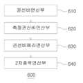
2 is a diagram showing components of an operation unit that is a part of the present invention.
이하 첨부된 도면을 바탕으로 본 발명의 바람직한 실시예에 대해 설명한다. 다만, 본 발명의 권리범위는 특허청구범위 기재에 의하여 파악되어야 한다. 또한 본 발명의 요지를 모호하게 하는 공지기술의 설명은 생략한다.Hereinafter, a preferred embodiment of the present invention will be described based on the accompanying drawings. However, the scope of the present invention should be grasped by the description of the claims. In addition, descriptions of known techniques that obscure the subject matter of the present invention will be omitted.
본 발명은 휴대용 변압기 시험기에 관한 것으로서, 연산부를 PLC 회로로 구성함으로써, 측정대상 변압기(1)의 권선비(RATIO), 권선비에러(RATIO %ERROR), 2차출력(SEC OUTPUT)가 즉시 연산될 수 있는 휴대용 변압기 시험기에 관한 것이다.The present invention relates to a portable transformer tester, and by configuring an operation unit with a PLC circuit, the turns ratio (RATIO), turns ratio error (RATIO %ERROR), and the secondary output (SEC OUTPUT) of the
도 1은 본 발명에 따른 휴대용 변압기 시험기의 회로도이고, 도 2는 본 발명의 일부구성인 연산부의 구성요소를 나타내는 도면이다.1 is a circuit diagram of a portable transformer tester according to the present invention, and FIG. 2 is a view showing components of an operation unit that is a part of the present invention.
본 발명에 따른 휴대용 변압기 시험기는 도 1에 도시된 바와 같이, 전원공급부(100)와, 제1교류전압변환기(200)와, 제2교류전압변환기(300)와, 제3교류전압변환기(400)와, A/D컨버터(500)와, 연산부(600)와, 제어부(700)와, 표시부(800)를 포함하여 구성될 수 있다.The portable transformer tester according to the present invention, as shown in FIG. 1, includes a
전원공급부(100)에 대해 설명한다. 전원공급부(100)는 외부에서 입력되는 교류전원을 변압기(1)에 공급하는 부분으로서, 전원출력부(110)와, 다중변압부(120)와, 회로차단부(130)를 포함하여 구성될 수 있다.The
전원출력부(110)에 대해 설명한다. 전원출력부(110)는 외부에서 입력되는 교류전원이 출력되는 부분이다. 바람직하게는, AC 0.8V~10V 전원이 출력되도록 구성할 수 있지만, 반드시 이에 한정되는 것은 아니다.The
다중변압부(120)에 대해 설명한다. 다중변압부(120)는 전원출력부(110)에서 출력되는 교류전원의 전압값을 기설정된 복수개의 전압값 중 전압값으로 변압시키는 부분이다.The
여기서, 기설정된 복수개의 전압값은 제어부(700)에 입력된 1,2차권선전압값(PRI.V,SEC.V)에 대응되는 특정한 값으로 설정될 수 있다. 구체적으로, 상기 전압값을 0.8V, 2V, 5V, 10V 로 설정하는 것이 바람직하지만, 반드시 이에 한정되는 것은 아니다.Here, a plurality of preset voltage values may be set to specific values corresponding to primary and secondary winding voltage values (PRI.V, SEC.V) input to the
회로차단부(130)에 대해 설명한다. 회로차단부(130)는 전원출력부(110)와 다중변압부(120) 사이에 연결되어 회로를 개방 또는 단락시키는 부분이다.The
상기 회로차단부(130)와 다중변압부(120) 사이에는 제1릴레이(10)가 직렬적으로 연결될 수 있다. 상기 제1릴레이(10)는 다중변압부(120)를 on/off 하는 역할을 한다.The
제1교류전압변환기(200)에 대해 설명한다. 제1교류전압변환기(200)는 변압기(1)의 일측에 연결되는 부분으로서, 제어부(700)에 입력된 2차권선전압값(SEC.V)을 측정하여 이에 대응되는 교류전원을 직류전원으로 변환한 후 A/D컨버터(500)로 인가하는 부분이다.The first
바람직하게는, 제1교류전압변환기(200)에서 AC 10V 가 DC 4~20mA 로 변환되도록 구성할 수 있지만, 반드시 이에 한정되는 것은 아니다.Preferably, the first
상기 다중변압부(120)와 제1교류전압변환기(200) 사이에는 제2릴레이(20)가 연결될 수 있다. 상기 제2릴레이(20)는 기설정된 복수개의 전압값 중 다중변압부(120)에서 변압된 전압값에 대응되는 전압값을 통과시키는 부분이다.A
제2릴레이(20)는 상호 병렬적으로 연결되는 제2-1릴레이(21), 제2-2릴레이(22), 제2-3릴레이(23), 2-4릴레이(24)를 포함하여 구성될 수 있다.The
상기 제2-1릴레이(21)는 제1변압값의 통과를 on/off 하는 부분이고, 제2-2릴레이(22)는 제2변압값의 통과를 on/off 하는 부분이고, 제2-3릴레이(23)는 제3변압값의 통과를 on/off 하는 부분이고, 2-4릴레이(24)는 제4변압값의 통과를 on/off 하는 부분이다.The 2-1
여기서, 제1변압값은 0.8V, 제2변압값은 2V, 제3변압값은 5V, 제4변압값은 10V로 설정하는 것이 바람직하다. 다만, 반드시 이에 한정되는 것은 아니고, 제2릴레이(20)의 갯수를 가감할 수 있음은 물론이고, 다른 특정한 변압값으로 설정할 수도 있다.Here, it is preferable to set the first transformed value to 0.8V, the second transformed value to 2V, the third transformed value to 5V, and the fourth transformed value to 10V. However, the present invention is not necessarily limited thereto, and the number of the
상기 제1교류전압변환기(200)와 변압기(1) 사이에는 제3릴레이(30)가 연결될 수 있다. 여기서, 제3릴레이(30)는 3상의 2차권선전압값(SEC.V) 중에서 어느 하나의 전압값의 통과를 on/off 하는 부분으로서, 바람직하게는, 상호 병렬적으로 연결되는 제3-1릴레이(31), 제3-2릴레이(32), 제3-3릴레이(33)를 포함하여 구성될 수 있다.A
제2교류전압변환기(300)에 대해 설명한다. 제2교류전압변환기(300)는 변압기(1)의 타측에 연결되는 부분으로서, 제어부(700)에 입력된 1차권선전압값(PRI.V)이 제1전압값을 가지는 경우, 제1전압값에 대응되는 교류전원을 직류전원으로 변환한 후 A/D컨버터(500)로 인가하는 부분이다.The second
여기서, 제1전압값은 AC 50V 로 설정하는 것이 바람직하고, 이 경우 제2교류전압변환기(300)에서는 AC 50V 가 DC 4~20mA 로 변환될 수 있다. 다만, 반드시 이에 한정되는 것은 아니다.Here, it is preferable to set the first voltage value to AC 50V. In this case, the second
상기 제2교류전압변환기(300)와 변압기(1) 사이에는 제4,5릴레이(40,50)가 직렬적으로 연결될 수 있다.The fourth and
여기서, 제4릴레이(40)는 3상의 1차권선전압값(PRI.V) 중에서 어느 하나의 전압값의 통과를 on/off 하는 부분으로서, 상호 병렬적으로 연결되는 제4-1릴레이(41), 제4-2릴레이(42), 제4-3릴레이(43)를 포함하여 구성될 수 있다.Here, the
제5릴레이(50)는 제4릴레이(40)를 통과한 전압값이 제2교류전압변환기(300)에 입력되는 것을 on/off 하는 부분이다.The
제3교류전압변환기(400)에 대해 설명한다. 제3교류전압변환기(400)는 변압기(1)의 타측에 연결되되, 제2교류전압변환기(300)와 병렬적으로 연결되는 부분으로서, 제어부(700)에 입력된 1차권선전압값(PRI.V)이 제2전압값을 가지는 경우, 제2전압값에 대응되는 교류전원을 직류전원으로 변환한 후 A/D컨버터(500)로 인가하는 부분이다.The third
여기서, 제2전압값은 AC 100V 로 설정하는 것이 바람직하고, 이 경우 제3교류전압변환기(400)에서는 AC 100V 가 DC 4~20mA 로 변환될 수 있다. 다만, 반드시 이에 한정되는 것은 아니다.Here, it is preferable to set the second voltage value to AC 100V. In this case, the third
상기 제3교류전압변환기(400)와 변압기(1) 사이에는 제4,6릴레이(40,60)가 직렬적으로 연결될 수 있다.Fourth and
여기서, 제4릴레이(40)는 전술한 바와 같이, 3상의 1차권선전압값(PRI.V) 중에서 어느 하나의 전압값의 통과를 on/off 하는 부분으로서, 바람직하게는, 상호 병렬적으로 연결되는 제4-1릴레이(41), 제4-2릴레이(42), 제4-3릴레이(43)를 포함하여 구성될 수 있다.Here, as described above, the
제6릴레이(60)는 제4릴레이(40)를 통과한 전압값이 제3교류전압변환기(400)에 입력되는 것을 on/off 하는 부분이다.The
A/D컨버터(500)에 대해 설명한다. A/D컨버터(500)는 제1,2,3교류전압변환기(200,300,400)에서 변환된 전원을 입력받아 아날로그 신호를 디지털 신호로 변환시키는 부분이다.The A/
연산부(600)에 대해 설명한다. 연산부(600)는 PLC 회로로 이루어지되, A/D컨버터(500)에 의하여 변환된 디지털 신호를 입력받아 권선비(RATIO), 권선비에러(RATIO %ERROR), 2차출력(SEC OUTPUT)을 즉시 연산하는 부분이다.The
상기 상기 연산부(600)는 도 2에 도시된 바와 같이, 권선비연산부(610)와, 측정권선비연산부(620)와, 권선비에러연산부(630)와, 2차출력연산부(640)를 포함하여 구성될 수 있다.As shown in FIG. 2, the
상기 권선비연산부(610)는 제어부(700)에 입력된 1차권선전압값(PRI.V) 및 2차권선전압값(SEC.V)을 이용하여 권선비(RATIO)를 연산하는 부분이다.The winding
구체적으로, RATIO = PRI.V / SEC.V 로 연산된다.Specifically, it is calculated as RATIO = PRI.V / SEC.V.
상기 측정권선비연산부(620)는 제2교류전압변환기(300) 또는 제3교류전압변환기(400)에서 측정된 1차권선측정전압값(RATED PRI.V)과 제1교류전압변환기(200)에서 측정된 2차권선측정전압값(RATED SEC.V)을 이용하여 측정권선비(RATED RATIO)를 연산하는 부분이다.The measurement winding
구체적으로, RATED RATIO = RATED PRI.V / RATED SEC.V 로 연산된다.Specifically, it is calculated as RATED RATIO = RATED PRI.V / RATED SEC.V.
상기 권선비에러연산부(630)는 권선비연산부(610)에서 연산된 권선비(RATIO)와 측정권선비연산부(620)에서 연산된 측정권선비(RATED RATIO)를 이용하여 권선비에러(RATIO %ERROR)를 연산하는 부분이다.The turns ratio
구체적으로, RATIO %ERROR = ((RATED RATIO - RATIO)*100) / RATED RATIO 로 연산된다.Specifically, it is calculated as RATIO %ERROR = ((RATED RATIO-RATIO)*100) / RATED RATIO.
상기 2차출력연산부(640)는 제어부(700)에 입력된 1차권선전압값(PRI.V) 및 권선비연산부(610)에서 연산된 권선비(RATIO)를 이용하여 2차출력(SEC OUTPUT)을 연산하는 부분이다.The secondary
구체적으로, SEC OUTPUT = PRI.V * RATIO 로 연산된다.Specifically, it is calculated as SEC OUTPUT = PRI.V * RATIO.
제어부(700)에 대해 설명한다. 제어부(700)는 변압기(1)의 1차권선전압값(PRI.V)과 2차권선전압값(SEC.V)이 입력되는 부분이다.The
표시부(800)에 대해 설명한다. 표시부(800)에서는 변압기(1)의 1차권선전압값(PRI.V)과 2차권선전압값(SEC.V)이 입력될 수 있도록 사용자 인터페이스를 제공하거나, 연산부(600)에서 연산된 권선비(RATIO), 권선비에러(RATIO %ERROR), 2차출력(SEC OUTPUT)이 화면상에 출력되는 부분이다.The display unit 800 will be described. The display unit 800 provides a user interface so that the primary winding voltage value (PRI.V) and the secondary winding voltage value (SEC.V) of the
상기 제어부(700) 및 표시부(700)는 HMI 터치스크린 방식으로 구현되거나, PC CIMON 방식으로 구현될 수 있다.The
이상에서 설명한 본 발명은 전술한 실시예 및 첨부된 도면에 의해 한정되는 것은 아니고, 본 발명의 기술적 사상을 벗어나지 않는 범위 내에서 여러 가지 치환, 변형 및 변경 가능함은 본 발명이 속하는 기술분야에서 통상의 지식을 가진 자에게 있어서 명백할 것이다.The present invention described above is not limited by the above-described embodiments and the accompanying drawings, and various substitutions, modifications, and changes are possible within the scope of the technical spirit of the present invention. It will be obvious to those who have knowledge.
100 : 전원공급부
110 : 전원입력부
120 : 다중변압부
130 : 회로차단부
200 : 제1교류전압변환기
300 : 제2교류전압변환기
400 : 제3교류전압변환기
500 : A/D컨버터
600 : 연산부
610 : 권선비연산부
620 : 측정권선비연산부
630 : 권선비에러연산부
640 : 2차출력연산부
700 : 제어부
800 : 표시부
10 : 제1릴레이
20 : 제2릴레이
21 : 제2-1릴레이
22 : 제2-2릴레이
23 : 제2-3릴레이
24 : 제2-4릴레이
30 : 제3릴레이
31 : 제3-1릴레이
32 : 제3-2릴레이
33 : 제3-3릴레이
40 : 제4릴레이
41 : 제4-1릴레이
42 : 제4-2릴레이
43 : 제4-3릴레이
50 : 제5릴레이
1 : 변압기100: power supply
110: power input unit
120: multiple transformer
130: circuit breaker
200: first AC voltage converter
300: second AC voltage converter
400: 3rd AC voltage converter
500: A/D converter
600: operation unit
610: winding ratio calculation unit
620: Measurement winding ratio calculation unit
630: Turns ratio error calculation unit
640: secondary output calculation unit
700: control unit
800: display
10: first relay
20: second relay
21: relay 2-1
22: relay 2-2
23: relay 2-3
24: relay 2-4
30: 3rd relay
31: 3-1 relay
32: 3-2 relay
33: 3-3 relay
40: 4th relay
41: relay 4-1
42: relay 4-2
43: relay 4-3
50: 5th relay
1: transformer
Claims (4)
Translated fromKorean변압기(1)의 일측에 연결되는 제1교류전압변환기(200);
변압기(1)의 타측에 병렬적으로 연결되는 제2,3교류전압변환기(300,400);
제1,2,3교류전압변환기(200,300,400)에서 변환된 전원을 입력받아 아날로그 신호를 디지털 신호로 변환시키는 A/D컨버터(500);
PLC 회로로 이루어지되, A/D컨버터(500)에 의하여 변환된 디지털 신호를 입력받아 권선비(RATIO), 권선비에러(RATIO %ERROR), 2차출력(SEC OUTPUT)을 연산하는 연산부(600);
변압기(1)의 1차권선전압값(PRI.V)과 2차권선전압값(SEC.V)이 입력되는 제어부(700);
연산부(600)에서 연산된 권선비(RATIO), 권선비에러(RATIO %ERROR), 2차출력(SEC OUTPUT)이 화면상에 출력되는 표시부(800);를 포함하고,
상기 전원공급부(100)는
외부에서 입력되는 교류전원이 출력되는 전원출력부(110)와,
전원출력부(110)에서 출력되는 교류전원의 전압값을 기설정된 복수개의 전압값 중 어느 하나의 전압값으로 변압시키는 다중변압부(120)와,
전원출력부(110)와 다중변압부(120) 사이에 연결되어 회로를 개방 또는 단락시키는 회로차단부(130)를 포함하고,
상기 제1교류전압변환기(200)는
제어부(700)에 입력된 2차권선전압값(SEC.V)에 대응되는 교류전원을 직류전원으로 변환한 후 A/D컨버터(500)로 인가하고,
상기 제2교류전압변환기(300)는
제어부(700)에 입력된 1차권선전압값(PRI.V)이 제1전압값을 가지는 경우, 제1전압값에 대응되는 교류전원을 직류전원으로 변환한 후 A/D컨버터(500)로 인가하고,
상기 제3교류전압변환기(400)는
제어부(700)에 입력된 1차권선전압값(PRI.V)이 제2전압값을 가지는 경우, 제2전압값에 대응되는 교류전원을 직류전원으로 변환한 후 A/D컨버터(500)로 인가하고,
상기 연산부(600)는
제어부(700)에 입력된 1차권선전압값(PRI.V) 및 2차권선전압값(SEC.V)을 이용하여 권선비(RATIO)를 연산하는 권선비연산부(610)와,
제2교류전압변환기(300) 또는 제3교류전압변환기(400)에서 측정된 1차권선측정전압값(RATED PRI.V)과 제1교류전압변환기(200)에서 측정된 2차권선측정전압값(RATED SEC.V)을 이용하여 측정권선비(RATED RATIO)를 연산하는 측정권선비연산부(620)와,
권선비연산부(610)에서 연산된 권선비(RATIO)와 측정권선비연산부(620)에서 연산된 측정권선비(RATED RATIO)를 이용하여 권선비에러(RATIO %ERROR)를 연산하는 권선비에러연산부(630)와,
제어부(700)에 입력된 1차권선전압값(PRI.V) 및 권선비연산부(610)에서 연산된 권선비(RATIO)를 이용하여 2차출력(SEC OUTPUT)을 연산하는 2차출력연산부(640)를 포함하고,
상기 권선비연산부(610)에서 연산되는 권선비(RATIO)는
RATIO = PRI.V / SEC.V 로 연산되고,
상기 측정권선비연산부(620)에서 연산되는 측정권선비(RATED RATIO)는
RATED RATIO = RATED PRI.V / RATED SEC.V 로 연산되고,
상기 권선비에러연산부(630)에서 연산되는 권선비에러(RATIO %ERROR)는
RATIO %ERROR = ((RATED RATIO - RATIO)*100) / RATED RATIO 로 연산되고,
상기 2차출력연산부(640)에서 연산되는 2차출력(SEC OUTPUT)은
SEC OUTPUT = PRI.V * RATIO 로 연산되는 것을 특징으로 하는
휴대용 변압기 시험기.A power supply unit 100 for supplying an AC power input from the outside to the transformer 1;
A first AC voltage converter 200 connected to one side of the transformer 1;
Second and third AC voltage converters 300 and 400 connected in parallel to the other side of the transformer 1;
An A/D converter 500 for converting an analog signal into a digital signal by receiving the power converted from the first, second, and third AC voltage converters 200, 300, and 400;
An operation unit 600 configured as a PLC circuit, receiving the digital signal converted by the A/D converter 500 and calculating a turns ratio (RATIO), a turns ratio error (RATIO %ERROR), and a secondary output (SEC OUTPUT);
A controller 700 to which a primary winding voltage value (PRI.V) and a secondary winding voltage value (SEC.V) of the transformer 1 are input;
Including; a display unit 800 for outputting a turns ratio (RATIO), a turns ratio error (RATIO %ERROR), and a secondary output (SEC OUTPUT) calculated by the operation unit 600 on the screen; and
The power supply unit 100 is
A power output unit 110 for outputting an AC power input from the outside;
A multi-transformer 120 transforming the voltage value of the AC power output from the power output unit 110 into any one of a plurality of preset voltage values,
A circuit breaker 130 connected between the power output unit 110 and the multi-transformer unit 120 to open or short a circuit,
The first AC voltage converter 200 is
After converting the AC power corresponding to the secondary winding voltage value (SEC.V) input to the control unit 700 to DC power, it is applied to the A/D converter 500,
The second AC voltage converter 300 is
When the primary winding voltage value (PRI.V) input to the control unit 700 has a first voltage value, the AC power corresponding to the first voltage value is converted into DC power and then converted to the A/D converter 500. Authorized,
The third AC voltage converter 400 is
When the primary winding voltage value (PRI.V) input to the control unit 700 has a second voltage value, the AC power corresponding to the second voltage value is converted into DC power and then converted to the A/D converter 500. Authorized,
The operation unit 600 is
A winding ratio calculating unit 610 that calculates a turns ratio (RATIO) using a primary winding voltage value (PRI.V) and a secondary winding voltage value (SEC.V) input to the control unit 700;
The primary winding measurement voltage value (RATED PRI.V) measured by the second AC voltage converter 300 or the third AC voltage converter 400 and the secondary winding measurement voltage value measured by the first AC voltage converter 200 A measurement winding ratio calculation unit 620 that calculates a measurement winding ratio (RATED RATIO) using (RATED SEC.V),
A turns ratio error calculation unit 630 that calculates a turns ratio error (RATIO% ERROR) using the turns ratio (RATIO) calculated by the winding ratio calculation unit 610 and the measured winding ratio (RATED RATIO) calculated by the measurement winding ratio calculation unit 620,
The secondary output calculation unit 640 that calculates the secondary output (SEC OUTPUT) using the primary winding voltage value (PRI.V) input to the control unit 700 and the turns ratio (RATIO) calculated by the winding ratio calculation unit 610 Including,
The turns ratio (RATIO) calculated by the turns ratio calculation unit 610 is
RATIO = PRI.V / SEC.V calculated,
The measurement winding ratio (RATED RATIO) calculated by the measurement winding ratio calculation unit 620 is
RATED RATIO = RATED PRI.V / RATED SEC.V is calculated,
The turns ratio error (RATIO %ERROR) calculated by the turns ratio error calculation unit 630 is
RATIO %ERROR = ((RATED RATIO-RATIO)*100) / Calculated as RATED RATIO,
The secondary output (SEC OUTPUT) calculated by the secondary output calculation unit 640 is
SEC OUTPUT = PRI.V * RATIO
Portable transformer tester.
Priority Applications (1)
| Application Number | Priority Date | Filing Date | Title |
|---|---|---|---|
| KR1020200087523AKR102194779B1 (en) | 2020-07-15 | 2020-07-15 | Portable Potential Transformer Tester |
Applications Claiming Priority (1)
| Application Number | Priority Date | Filing Date | Title |
|---|---|---|---|
| KR1020200087523AKR102194779B1 (en) | 2020-07-15 | 2020-07-15 | Portable Potential Transformer Tester |
Publications (1)
| Publication Number | Publication Date |
|---|---|
| KR102194779B1true KR102194779B1 (en) | 2020-12-23 |
Family
ID=74089386
Family Applications (1)
| Application Number | Title | Priority Date | Filing Date |
|---|---|---|---|
| KR1020200087523AActiveKR102194779B1 (en) | 2020-07-15 | 2020-07-15 | Portable Potential Transformer Tester |
Country Status (1)
| Country | Link |
|---|---|
| KR (1) | KR102194779B1 (en) |
Cited By (2)
| Publication number | Priority date | Publication date | Assignee | Title |
|---|---|---|---|---|
| KR102296618B1 (en)* | 2021-02-25 | 2021-09-01 | 송상훈 | Ratio Error And Phase displacement Error Tester For Portable Current Transformer |
| KR20230093588A (en) | 2021-12-20 | 2023-06-27 | 엘에스일렉트릭(주) | System and method for temperature-rise test automation |
Citations (3)
| Publication number | Priority date | Publication date | Assignee | Title |
|---|---|---|---|---|
| KR100206655B1 (en)* | 1996-02-23 | 1999-07-01 | 이종훈 | Portable current transformer tester |
| KR100439646B1 (en) | 2001-08-28 | 2004-07-12 | 주식회사프로컴시스템 | Portable Transformer Tester |
| JP4035897B2 (en)* | 1998-08-21 | 2008-01-23 | 日新電機株式会社 | Transformer circuit inspection equipment |
- 2020
- 2020-07-15KRKR1020200087523Apatent/KR102194779B1/enactiveActive
Patent Citations (3)
| Publication number | Priority date | Publication date | Assignee | Title |
|---|---|---|---|---|
| KR100206655B1 (en)* | 1996-02-23 | 1999-07-01 | 이종훈 | Portable current transformer tester |
| JP4035897B2 (en)* | 1998-08-21 | 2008-01-23 | 日新電機株式会社 | Transformer circuit inspection equipment |
| KR100439646B1 (en) | 2001-08-28 | 2004-07-12 | 주식회사프로컴시스템 | Portable Transformer Tester |
Cited By (2)
| Publication number | Priority date | Publication date | Assignee | Title |
|---|---|---|---|---|
| KR102296618B1 (en)* | 2021-02-25 | 2021-09-01 | 송상훈 | Ratio Error And Phase displacement Error Tester For Portable Current Transformer |
| KR20230093588A (en) | 2021-12-20 | 2023-06-27 | 엘에스일렉트릭(주) | System and method for temperature-rise test automation |
Similar Documents
| Publication | Publication Date | Title |
|---|---|---|
| KR102180016B1 (en) | Portable Current Transformer Excitation And Core Characteristics Tester | |
| KR102296618B1 (en) | Ratio Error And Phase displacement Error Tester For Portable Current Transformer | |
| US5821742A (en) | Computerized solid state energy meter test system and method of testing | |
| KR100439646B1 (en) | Portable Transformer Tester | |
| KR102194779B1 (en) | Portable Potential Transformer Tester | |
| CN105548948A (en) | Device and method for testing digitalization electric energy metering system | |
| KR102191783B1 (en) | Portable Current Transformer Ratio Tester | |
| CN106597351A (en) | A Realization Method of On-line Real-time Monitoring of Electric Energy Meter Calibration Device | |
| CN107942192A (en) | A kind of controller switching equipment CT automatic test approach and system | |
| Adamo et al. | Channel characterization of an open source energy meter | |
| CN202486269U (en) | State tester of electrical equipment | |
| CN106483397A (en) | A kind of electric energy quality detection device of high accuracy high bandwidth and measuring method | |
| Tung et al. | An Arduino-Based System for Monitoring and Protecting Overvoltage and Undervoltage. | |
| CN203337792U (en) | Motor type test system | |
| Fuzhou et al. | Error analysis of capacitor voltage transformer in the operation environment | |
| Gutwald et al. | Measurement technology in industrial low voltage DC grids–Requirements and selection procedure | |
| CN106772197B (en) | Calibration device for load box of mutual inductor | |
| CN103023497B (en) | The digital signal of selsyn module and analog signal conversion accuracy method of testing | |
| CN104849532B (en) | A precision current sensor | |
| CN114137303B (en) | Measuring device and measuring method | |
| Bonisławski et al. | Automated test stand for transformer inrush current measurement | |
| CN111208468A (en) | Harmonic performance tester for electronic voltage transformer | |
| Volovich et al. | Experimental operation of the adaptive electronic instrument transformer of current and voltage | |
| KR100439647B1 (en) | Portable Anglemeter | |
| Faiz et al. | New controller for an electronic tap changer—Part II: Measurement algorithm and test results |
Legal Events
| Date | Code | Title | Description |
|---|---|---|---|
| PA0109 | Patent application | Patent event code:PA01091R01D Comment text:Patent Application Patent event date:20200715 | |
| PA0201 | Request for examination | ||
| PA0302 | Request for accelerated examination | Patent event date:20200715 Patent event code:PA03022R01D Comment text:Request for Accelerated Examination | |
| PE0902 | Notice of grounds for rejection | Comment text:Notification of reason for refusal Patent event date:20200827 Patent event code:PE09021S01D | |
| E701 | Decision to grant or registration of patent right | ||
| PE0701 | Decision of registration | Patent event code:PE07011S01D Comment text:Decision to Grant Registration Patent event date:20201216 | |
| GRNT | Written decision to grant | ||
| PR0701 | Registration of establishment | Comment text:Registration of Establishment Patent event date:20201217 Patent event code:PR07011E01D | |
| PR1002 | Payment of registration fee | Payment date:20201217 End annual number:3 Start annual number:1 | |
| PG1601 | Publication of registration | ||
| PR1001 | Payment of annual fee | Payment date:20231206 Start annual number:4 End annual number:4 | |
| PR1001 | Payment of annual fee | Payment date:20241211 Start annual number:5 End annual number:5 |