KR102193768B1 - Robot and control method for the same - Google Patents
Robot and control method for the sameDownload PDFInfo
- Publication number
- KR102193768B1 KR102193768B1KR1020140004467AKR20140004467AKR102193768B1KR 102193768 B1KR102193768 B1KR 102193768B1KR 1020140004467 AKR1020140004467 AKR 1020140004467AKR 20140004467 AKR20140004467 AKR 20140004467AKR 102193768 B1KR102193768 B1KR 102193768B1
- Authority
- KR
- South Korea
- Prior art keywords
- robot
- wearer
- hardness information
- ground
- walking
- Prior art date
- Legal status (The legal status is an assumption and is not a legal conclusion. Google has not performed a legal analysis and makes no representation as to the accuracy of the status listed.)
- Active
Links
Images


Classifications
- B—PERFORMING OPERATIONS; TRANSPORTING
- B25—HAND TOOLS; PORTABLE POWER-DRIVEN TOOLS; MANIPULATORS
- B25J—MANIPULATORS; CHAMBERS PROVIDED WITH MANIPULATION DEVICES
- B25J9/00—Programme-controlled manipulators
- B25J9/0006—Exoskeletons, i.e. resembling a human figure
- G—PHYSICS
- G05—CONTROLLING; REGULATING
- G05B—CONTROL OR REGULATING SYSTEMS IN GENERAL; FUNCTIONAL ELEMENTS OF SUCH SYSTEMS; MONITORING OR TESTING ARRANGEMENTS FOR SUCH SYSTEMS OR ELEMENTS
- G05B2219/00—Program-control systems
- G05B2219/30—Nc systems
- G05B2219/40—Robotics, robotics mapping to robotics vision
- G05B2219/40305—Exoskeleton, human robot interaction, extenders
- Y—GENERAL TAGGING OF NEW TECHNOLOGICAL DEVELOPMENTS; GENERAL TAGGING OF CROSS-SECTIONAL TECHNOLOGIES SPANNING OVER SEVERAL SECTIONS OF THE IPC; TECHNICAL SUBJECTS COVERED BY FORMER USPC CROSS-REFERENCE ART COLLECTIONS [XRACs] AND DIGESTS
- Y10—TECHNICAL SUBJECTS COVERED BY FORMER USPC
- Y10S—TECHNICAL SUBJECTS COVERED BY FORMER USPC CROSS-REFERENCE ART COLLECTIONS [XRACs] AND DIGESTS
- Y10S901/00—Robots
- Y10S901/01—Mobile robot
- Y—GENERAL TAGGING OF NEW TECHNOLOGICAL DEVELOPMENTS; GENERAL TAGGING OF CROSS-SECTIONAL TECHNOLOGIES SPANNING OVER SEVERAL SECTIONS OF THE IPC; TECHNICAL SUBJECTS COVERED BY FORMER USPC CROSS-REFERENCE ART COLLECTIONS [XRACs] AND DIGESTS
- Y10—TECHNICAL SUBJECTS COVERED BY FORMER USPC
- Y10S—TECHNICAL SUBJECTS COVERED BY FORMER USPC CROSS-REFERENCE ART COLLECTIONS [XRACs] AND DIGESTS
- Y10S901/00—Robots
- Y10S901/46—Sensing device
Landscapes
- Engineering & Computer Science (AREA)
- Robotics (AREA)
- Mechanical Engineering (AREA)
- Rehabilitation Tools (AREA)
- Manipulator (AREA)
Abstract
Translated fromKorean
Description
Translated fromKorean로봇 및 로봇의 제어 방법이 개시된다. 더욱 상세하게는 사용자 주변의 환경에 따라 로봇을 안정적으로 제어할 수 있는 로봇 및 로봇의 제어 방법이 개시된다.A robot and a method of controlling the robot are disclosed. In more detail, a robot capable of stably controlling a robot according to an environment around a user and a method of controlling the robot are disclosed.
로봇은 군사, 산업, 의료 분야에서 다양한 목적으로 사용되고 있다. 이들 로봇 중에서 보행 보조 로봇은 실내외 보행 환경에서 보행이 불편한 보행자를 부축하고 보행을 도와주는 로봇을 말한다. 이러한 보행 보조 로봇은 부축형 보행 보조 로봇과 착용형 보행 보조 로봇을 포함할 수 있다.Robots are used for various purposes in military, industrial, and medical fields. Among these robots, the walking assistance robot refers to a robot that supports and assists pedestrians who are inconvenient to walk in indoor and outdoor walking environments. Such a walking assistance robot may include an auxiliary axis walking assistance robot and a wearable walking assistance robot.
부축형 보행 보조 로봇은 보행자의 보행 의지를 파악하여 보행자의 보행을 보조하는 로봇이다. 부축형 보행 보조 로봇은 몸체, 몸체 상부에 마련된 핸들바, 몸체 하부에 마련되어 몸체의 이동을 가능하게 하는 복수의 바퀴를 포함할 수 있다.The auxiliary walking assist robot is a robot that assists the pedestrian by grasping the will of the pedestrian to walk. The auxiliary walking assist robot may include a body, a handle bar provided on the upper body, and a plurality of wheels provided under the body to enable movement of the body.
착용형 보행 보조 로봇은 하지 근력이 저하된 노인 및 환자의 재활 치료와 근력 증진을 도모하기 위한 로봇으로, 보행자의 하지에 착용될 수 있도록 외골격 구조를 갖는다.The wearable walking assistance robot is a robot for rehabilitation treatment and improvement of muscle strength for the elderly and patients with lower leg muscle strength, and has an exoskeleton structure to be worn on the lower leg of a pedestrian.
한국공개특허공보 10-2011-0125289Korean Patent Publication 10-2011-0125289
착용자 주변의 보행 환경에 따라 보행 보조 모드를 자동으로 전환할 수 있는 로봇 및 로봇의 제어 방법이 개시된다.Disclosed are a robot capable of automatically switching a walking assistance mode according to a walking environment around a wearer and a method of controlling the robot.
상술한 과제를 해결하기 위하여, 로봇의 제어 방법의 일 실시예는 착용자의 진행 방향의 지면에 대한 경도 정보를 계산하는 단계; 및 상기 계산된 경도 정보에 따라 로봇을 제어하는 단계 포함한다.In order to solve the above-described problem, an embodiment of a method of controlling a robot may include calculating hardness information on a ground in a moving direction of a wearer; And controlling the robot according to the calculated hardness information.
상술한 과제를 해결하기 위하여, 로봇의 일 실시예는 착용자의 진행 방향의 지면에 대한 경도 정보를 계산하는 계산부; 및 상기 계산된 경도 정보에 따라 로봇을 제어하기 위한 제어신호를 생성하는 제어신호 생성부를 포함한다.In order to solve the above-described problem, an embodiment of the robot includes: a calculation unit for calculating hardness information on the ground in the direction of travel of the wearer; And a control signal generator for generating a control signal for controlling the robot according to the calculated hardness information.
로봇 주변의 환경에 맞추어 로봇의 제어 모드가 자동으로 변경되므로, 로봇의 사용성을 향상시킬 수 있다.Since the control mode of the robot is automatically changed according to the environment around the robot, the usability of the robot can be improved.
도 1은 보행 보조 로봇의 일 실시예에 대한 정면도이다.
도 2는 보행 보조 로봇의 일 실시예에 대한 배면도이다.
도 3은 보행 보조 로봇의 일 실시예에 대한 구성도이다.
도 4 보행 환경 지도의 일 실시예를 도시한 도면이다.
도 5는 보행 보조 로봇에 대한 기계 시스템의 수학적 모델을 예시한 도면이다.
도 6은 도 5에 도시된 지면의 수학적 모델을 예시한 도면이다.
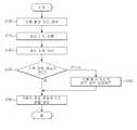
도 7은 보행 보조 로봇의 제어 방법에 대한 일 실시예를 도시한 흐름도이다.1 is a front view of an embodiment of a walking assistance robot.
2 is a rear view of an embodiment of a walking assist robot.
3 is a configuration diagram of an embodiment of a walking assist robot.
4 is a diagram showing an embodiment of a walking environment map.
5 is a diagram illustrating a mathematical model of a mechanical system for a walking assist robot.
6 is a diagram illustrating a mathematical model of the ground shown in FIG. 5.
7 is a flowchart illustrating an embodiment of a method for controlling a walking assist robot.
본 발명의 이점 및 특징, 그리고 그것들을 달성하는 방법은 첨부되는 도면과 함께 상세하게 후술되어 있는 실시예들을 참조하면 명확해질 것이다. 그러나 본 발명은 이하에서 개시되는 실시예들에 한정되는 것이 아니라 서로 다른 다양한 형태로 구현될 수 있으며, 단지 본 실시예들은 본 발명의 개시가 완전하도록 하고, 본 발명이 속하는 기술 분야에서 통상의 지식을 가진 자에게 발명의 범주를 완전하게 알려주기 위해 제공되는 것이며, 본 발명은 청구항의 범주에 의해 정의될 뿐이다.Advantages and features of the present invention, and a method of achieving them will become apparent with reference to the embodiments described below in detail together with the accompanying drawings. However, the present invention is not limited to the embodiments disclosed below, but may be implemented in a variety of different forms, and only these embodiments make the disclosure of the present invention complete, and common knowledge in the technical field to which the present invention pertains. It is provided to completely inform the scope of the invention to those who have, and the invention is only defined by the scope of the claims.
이하, 첨부된 도면들을 참조하여 보행 보조 로봇 및 그 제어 방법에 대한 실시예들을 설명한다. 도면에서 동일한 도면 부호는 동일한 구성 요소를 나타낸다.Hereinafter, embodiments of a walking assist robot and a control method thereof will be described with reference to the accompanying drawings. In the drawings, the same reference numerals denote the same components.
개시된 발명에 따른 로봇은 이동형 로봇 및 보행 보조 로봇을 포함할 수 있다. 이동형 로봇은 사람 없이도 이동이 가능한 무인 로봇 및 사람이 탑승할 수 있는 형태의 유인 로봇을 포함할 수 있다. 보행 보조 로봇은 부축형 보행 보조 로봇 및 착용형 보행 보조 로봇을 포함할 수 있다.The robot according to the disclosed invention may include a mobile robot and a walking assist robot. The mobile robot may include an unmanned robot capable of moving without a person and a manned robot in a form in which a person can ride. The walking assistance robot may include a sub-axis walking assistance robot and a wearable walking assistance robot.
부축형 보행 보조 로봇은 복수의 바퀴에 의해 이동 가능한 몸체, 몸체의 상부에 마련되어 사용자가 몸체의 이동 방향을 조절할 수 있으며, 사용자가 몸체를 기댈 수 있는 핸들바를 포함한다. 착용형 보행 보조 로봇은 사용자의 양 다리 중에서 적어도 하나의 다리에 착용될 수 있도록 외골격(外骨格) 구조를 가진다. 이하의 설명에서는 착용형 보행 보조 로봇을 예로 들어 설명하기로 한다. 또한, 설명의 편의를 위해 착용형 보행 보조 로봇을 '보행 보조 로봇'이라 칭하기로 한다.The auxiliary walking assist robot includes a body that can be moved by a plurality of wheels, a handle bar that is provided on an upper portion of the body and allows the user to adjust the movement direction of the body, and the user can lean the body. The wearable walking assistance robot has an exoskeleton structure so that it can be worn on at least one of the user's legs. In the following description, a wearable walking assist robot will be described as an example. In addition, for convenience of description, the wearable walking assistance robot will be referred to as a'walking assistance robot'.
도 1 및 도 2는 보행 보조 로봇의 일 실시예가 도시되어 있다. 도 1은 보행 보조 로봇의 일 실시예에 대한 정면도이고, 도 2는 착용형 보행 보조 로봇의 일 실시예에 대한 배면도이다.1 and 2 illustrate an embodiment of a walking assist robot. 1 is a front view of an embodiment of a walking assistance robot, and FIG. 2 is a rear view of an embodiment of a wearable walking assistance robot.
도 1 및 도 2에 도시된 바와 같이, 보행 보조 로봇(1)은 착용자의 왼쪽 다리 및 오른쪽 다리에 각각 착용될 수 있도록 외골격(外骨格) 구조를 가진다. 착용자는 보행 보조 로봇(1)을 착용한 상태에서 폄(extension), 구부림(flexion), 모음(adduction), 벌림(abduction) 등의 동작을 수행할 수 있다. 폄 동작은 관절을 펴는 운동을 말하며, 구부림 동작은 관절을 구부리는 운동을 말한다. 모음 동작은 다리를 몸의 중심축으로 가까이 하는 운동을 말한다. 벌림 동작은 몸의 중심축에서 멀어지는 방향으로 다리를 뻗는 운동을 말한다.1 and 2, the
도 1 및 도 2를 참조하면, 보행 보조 로봇(1)은 본체부(10), 제1 기구부(20R, 20L), 제2 기구부(30R, 30L) 및 제3 기구부(40R, 40L)를 포함할 수 있다.1 and 2, the
본체부(10)는 하우징(11), 허리 착용부(13), 허리 지지부(12) 및 전원(16)을 포함할 수 있다.The
하우징(11)에는 각종 부품이 내장될 수 있다. 하우징(11)에 내장되는 부품으로는, 중앙 처리 장치(CPU, central processing unit), 그래픽 처리 장치(GPU, graphic processing unit), 인쇄 회로 기판, 다양한 종류의 저장 장치 및 관성 측정 장치(Inertial Measurement Unit; IMU)가 설치될 수 있다. 예를 들어, 관성 측정 장치는 하우징(11)의 외부 또는 내부에 설치될 수 있다. 구체적으로, 관성 측정 장치는 하우징(11)의 내부에 마련된 인쇄회로기판 상에 설치될 수 있다. 관성 측정 장치는 관성 센서(inertial sensor)를 포함할 수 있다. 관성 센서는 가속도 및 각속도를 측정할 수 있다.Various components may be embedded in the
중앙 처리 장치는 마이크로 프로세서일 수 있다. 마이크로 프로세서는 실리콘 칩에 산술 논리 연산기, 레지스터, 프로그램 카운터, 명령 디코더나 제어 회로 등이 설치되어 있는 처리 장치이다. 중앙 처리 장치는 착용자로부터 지명 정보가 입력되는 경우, 저장 장치에서 지면 정보와 관련된 보행 환경 지도를 검색하고, 검색된 보행 환경 지도 상에 착용자의 초기 위치를 설정할 수 있다. 이 후, 착용자가 보행하여 위치가 변하는 경우, 중앙 처리 장치는 센서부의 각종 센서에서 감지된 정보에 기초하여 착용자의 현재 위치를 추정할 수 있다. 그리고 추정된 현재 위치 및 보행 환경 지도에 기초하여 현재 위치 주변의 보행 환경을 판단할 수 있다. 이 후, 보행 환경에 적합한 제어 모드를 선택하고, 선택된 제어 모드에 따라 기구부(20R, 20L, 30R, 30L, 40R, 40L)의 동작을 제어하기 위한 제어신호를 생성할 수 있다.The central processing unit may be a microprocessor. A microprocessor is a processing device in which arithmetic and logic operators, registers, program counters, instruction decoders and control circuits are installed on a silicon chip. When the place name information is input from the wearer, the central processing unit may search for a walking environment map related to the ground information from the storage device and set an initial position of the wearer on the searched walking environment map. Thereafter, when the wearer walks and the position changes, the central processing unit may estimate the current position of the wearer based on information detected by various sensors of the sensor unit. In addition, the walking environment around the current location may be determined based on the estimated current location and the walking environment map. Thereafter, a control mode suitable for the walking environment may be selected, and a control signal for controlling the operation of the
그래픽 처리 장치는 마이크로 프로세서 중 주로 그래픽에 관련된 정보를 처리하는 처리 장치를 의미한다. 그래픽 처리 장치는 중앙 처리 장치의 그래픽 처리 기능을 보조하거나 단독으로 그래픽 처리를 수행할 수 있다. 그래픽 처리 장치는 중앙 처리 장치에서 검색된 보행 환경 지도에 대해 영상 처리를 수행할 수 있다. 예를 들면, 착용자의 초기 위치를 보행 환경 지도 상에 표시하거나, 착용자의 현재 위치가 추정되면, 추정된 현재 위치를 보행 환경 지도 상에 표시할 수 있다.The graphic processing unit refers to a processing unit that mainly processes information related to graphics among microprocessors. The graphic processing unit may assist the graphic processing function of the central processing unit or may perform graphic processing by itself. The graphic processing device may perform image processing on the walking environment map searched by the central processing device. For example, the initial position of the wearer may be displayed on a walking environment map, or when the current position of the wearer is estimated, the estimated current position may be displayed on the walking environment map.
인쇄 회로 기판은 소정의 회로가 인쇄되어 있는 기판으로, 인쇄 회로 기판에는 중앙 처리 장치, 그래픽 처리 장치 또는 다양한 저장 장치가 설치되어 있을 수 있다. 이러한 인쇄 회로 기판은 하우징(11)의 내측면에 고정될 수 있다.The printed circuit board is a board on which a predetermined circuit is printed, and a central processing unit, a graphic processing unit, or various storage devices may be installed on the printed circuit board. Such a printed circuit board may be fixed to the inner surface of the
하우징(11)에 내장된 저장 장치는 다양한 종류를 포함할 수 있다. 저장 장치로는 자기 디스크 표면을 자화시켜 데이터를 저장하는 자기 디스크 저장 장치, 다양한 종류의 메모리 반도체를 이용하여 데이터를 저장하는 반도체 메모리 장치를 예로 들 수 있다. 실시예에 따르면, 저장 장치에는 보행 환경 지도가 저장될 수 있다.The storage device built into the
보행 환경 지도는 지면에 대한 정보를 포함할 수 있다. 실시예에 따르면, 지면에 대한 정보는 지면에 대한 경도(단단함, hardness) 정보를 포함할 수 있다. 예를 들어, 지면은 콘크리트, 모래(즉, 운동장의 모래), 및 카펫 중 하나로 이루어질 수 있는데, 지면의 경도는 각 경우마다 다르다. 구체적으로, 카펫, 모래, 콘크리트의 순서로 지면의 경도는 증가한다. 다른 실시예에 따르면, 지면에 대한 정보는 지면에 대한 정도 정보 외에도 지면에 대한 기하학 정보를 더 포함할 수 있다. 지면에 대한 기하학 정보는 지면의 형태에 대한 정보를 의미하며, 지면의 형태는 예를 들어, 평지, 오르막 경사, 내리막 경사, 오르막 계단 및 내리막 계단 중 하나일 수 있다. 이하의 설명에서는 보행 환경 지도가 지면 정보로서, 지면에 대한 경도 정보 및 지면에 대한 기하학 정보를 모두 포함하는 경우를 예로 들어 설명하기로 한다.The pedestrian environment map may include information about the ground. According to an embodiment, the information on the ground may include information on the hardness (hardness) on the ground. For example, the ground may be made of one of concrete, sand (ie, sand of a playground), and carpet, the hardness of which is different in each case. Specifically, the hardness of the ground increases in the order of carpet, sand, and concrete. According to another embodiment, the information on the ground may further include geometric information on the ground in addition to information on the degree of the ground. Geometry information on the ground refers to information on the shape of the ground, and the shape of the ground may be, for example, one of a flat ground, an uphill slope, a downhill slope, an uphill staircase, and a downhill staircase. In the following description, a case where the walking environment map includes both hardness information on the ground and geometric information on the ground as ground information will be described as an example.
하우징(11)에 내장된 관성 측정 장치는 관성 센서(inertial sensor)를 포함할 수 있다. 관성 센서는 보행 보조 로봇(1)의 가속도 및 각속도를 측정할 수 있다.The inertial measuring device built into the
전원(16)은 하우징(11)의 외부에 배치될 수 있다. 전원(16)은 하우징(11)에 내장된 각종 부품이나 기구부(20R, 20L, 30R, 30L, 40R, 40L)로 동력을 공급할 수 있다. 도 1 및 도 2는 하우징(11)의 외부에 전원(16)이 배치된 경우를 도시하고 있으나, 전원(16)은 하우징(11)의 내부에 배치될 수도 있다. 구체적으로, 하우징(11)의 내부에 마련된 인쇄회로기판 상에 배치될 수도 있다. 전원(16)은 하우징(11) 또는 하우징(11) 내의 인쇄회로기판으로부터 분리 가능하도록 구현되거나, 외부 장치(미도시)에 의해 충전 가능한 형태로 구현될 수 있다.The
허리 착용부(13)는 하우징(11)을 착용자의 허리에 고정시키는 역할을 한다. 허리 착용부(13)는 착용자의 허리를 지지할 수 있도록 만곡된 평면판의 형상을 가질 수 있다. 도면에 도시되지는 않았으나, 허리 착용부(13)에는 허리 착용부(13)를 착용자의 허리에 고정시키기 위한, 고정부를 더 포함할 수 있다. 고정부는 예를 들어, 밴드나 벨트 형태로 구현될 수 있다. 고정부는 길이가 조절될 수 있도록 구현될 수 있다. 이 경우, 고정부는 착용자의 허리 둘레에 상관 없이 허리 착용부(13)를 착용자의 허리에 고정시킬 수 있다.The
허리 지지부(12)는 허리 착용부(13)에 연결된다. 허리 지지부(12)는 도 1 및 도 2에 도시된 바와 같이, 착용자의 등을 지지할 수 있도록 만곡된 평면판의 형상을 가질 수 있으며, 일단이 착용자의 양 어깨에 걸쳐질 수 있도록 구부러진 형상을 가질 수 있다. 그러나 허리 지지부(12)의 형상이 반드시 이로 한정되는 것은 아니며, 착용자의 등 및/또는 어깨 모양에 맞게 다양한 형상을 가질 수 있다.The
제1 기구부(20R, 20L)는 보행 동작에 있어서 착용자의 엉덩이 관절 및 대퇴부의 움직임을 보조할 수 있다. 이를 위해 제1 기구부(20R, 20L)는 제1 관절부(210R, 21L), 제1 링크부(22R, 22L) 및 제1 고정부(23R, 23L)를 포함할 수 있다.The first
제1 관절부(210R, 21L)는 인체의 엉덩이 관절에 대응된다. 제1 관절부(210R, 21L)는 인체의 엉덩이 관절의 동작 범위 내에서 회전하도록 구현될 수 있다. 이를 위해 제1 관절부(210R, 21L)는 적어도 1 자유도를 가질 수 있다.The first
여기서, 자유도(Degree of Freedom; DOF)란 정기구학(Forward Kinematics) 또는 역기구학(Inverse Kinematics)에서의 자유도를 말한다. 기구의 자유도란 기구의 독립적인 운동의 수, 또는 각 링크 간의 상대 위치의 독립된 운동을 결정하는 변수의 수를 말한다. 예를 들어, x축, y축, z축으로 이루어진 3차원 공간 상의 물체는 물체의 공간적인 위치(position)를 결정하기 위한 3 자유도(각 축에서의 위치)와, 물체의 공간적인 자세(orientation)를 결정하기 위한 3 자유도(각 축에 대한 회전 각도) 중에서 하나 이상의 자유도를 갖는다. 만약, 물체가 각각의 축을 따라 이동 가능하고, 각각의 축을 기준으로 회전 가능하다고 한다면, 이 물체는 6 자유도를 갖는 것으로 이해될 수 있다.Here, the degree of freedom (DOF) refers to a degree of freedom in Forward Kinematics or Inverse Kinematics. The degree of freedom of the instrument is the number of independent motions of the instrument, or the number of variables that determine the independent motion of the relative position between each link. For example, an object in a three-dimensional space consisting of the x-axis, y-axis, and z-axis has three degrees of freedom (position on each axis) to determine the spatial position of the object, and the spatial posture of the object ( orientation) to determine one or more of the three degrees of freedom (rotation angle about each axis). If an object is said to be movable along each axis and rotatable about each axis, this object can be understood as having 6 degrees of freedom.
제1 관절부(210R, 21L)에는 제1 구동부(도 3의 210R, 210L)가 마련될 수 있다. 제1 구동부(210R, 210L)는 본체부(10)에서 제공되는 제어신호에 따라 구동되어, 소정의 방향으로 다양한 크기의 회전력을 발생시킬 수 있다. 제1 구동부(210R, 210L)에서 발생된 회전력은 제1 관절부(210R, 21L)과 연결된 제1 링크부(22R, 22L)에 인가될 수 있다.A first driving unit (210R, 210L in FIG. 3) may be provided in the first
제1 구동부(210R, 210L)는 예를 들어, 모터, 진공 펌프(vacuum pump) 및 수압 펌프(hydraulic pump) 중 하나로 구현될 수 있으나, 이에 한정되는 것은 아니다. 이하의 설명에서는 제1 구동부(210R, 210L)가 모터로 구현되는 경우를 예로 들어 설명하기로 한다.The
제1 링크부(22R, 22L)는 제1 관절부(210R, 21L)와 물리적으로 연결된다. 제1 링크부(22R, 22L)는 제1 관절부(210R, 21L)의 제1 구동부(210R, 210L)에서 발생한 회전력에 따라 소정의 방향으로 회전될 수 있다.The
제1 링크부(22R, 22L)는 다양한 형상으로 구현될 수 있다. 일 예로, 제1 링크부(22R, 22L)는 복수의 마디가 서로 연결되어 있는 형상으로 구현될 수 있다. 이 때, 마디와 마디 사이에는 관절이 마련될 수 있으며, 제1 링크부(22R, 22L)는 이 관절에 의해 일정 범위 내에서 휘어질 수 있다. 다른 예로, 제1 링크부(22R, 22L)는 막대 형상으로 구현될 수 있다. 이 때, 제1 링크부(22R, 22L)는 일정한 범위 내에서 휘어질 수 있도록 가요성 있는 소재로 구현될 수 있다.The
제1 고정부(23R, 23L)는 제1 링크부(22R, 22L)에 마련될 수 있다. 제1 고정부(23R, 23L)는 제1 링크부(22R, 22L)를 착용자의 대퇴부에 고정시키는 역할을 한다. 도 1 및 도 2는 제1 링크부(22R, 22L)가 제1 고정부(23R, 23L)에 의해 착용자의 대퇴부의 외측에 고정되는 경우를 도시하고 있다. 제1 관절부(210R, 21L)가 회전함에 따라 제1 링크부(22R, 22L)가 회전하게 되면, 제1 링크부(22R, 22L)가 고정되어 있는 착용자의 대퇴부 역시 제1 링크부(22R, 22L)의 회전 방향과 동일한 방향으로 회전한다. 실시예에 따르면, 제1 고정부(23R, 23L)은 탄성력을 구비한 밴드, 벨트, 끈, 가요성 있는 금속 소재, 또는 이들의 조합으로 구현될 수도 있다.The
제2 기구부(30R, 30L)는 보행 동작에 있어서 착용자의 무릎 관절 및 하퇴부의 움직임을 보조할 수 있다. 이를 위해 제2 기구부(30R, 30L)는 제2 관절부(31R, 31L), 제2 링크부(32R, 32L) 및 제2 고정부(33R, 33L)를 포함할 수 있다.The
제2 관절부(31R, 31L)는 인체의 무릎 관절에 대응된다. 제2 관절부(31R, 31L)는 인체의 무릎 관절의 동작 범위 내에서 회전하도록 구현될 수 있다. 이를 위해 제2 관절부(31R, 31L)는 적어도 1 자유도를 가질 수 있다.The second
제2 관절부(31R, 31L)에는 제2 구동부(도 3의 310R, 310L)이 마련될 수 있다. 제2 구동부(310R, 310L)는 본체부(10)에서 제공되는 제어신호에 따라 구동되어, 소정의 방향으로 다양한 크기의 회전력을 발생시킬 수 있다. 제2 구동부(310R, 310L)에서 발생된 회전력은 제2 관절부(31R, 31L)와 연결된 제2 링크부(22R, 22L)에 인가될 수 있다.Second driving units (310R and 310L in FIG. 3) may be provided in the second
제2 구동부(310R, 310L)는 예를 들어, 모터, 진공 펌프 및 수압 펌프 중 하나로 구현될 수 있으나, 이에 한정되는 것은 아니다. 이하의 설명에서는 제2 구동부(310R, 310L)가 모터로 구현되는 경우를 예로 들어 설명하기로 한다.The
제2 링크부(32R, 32L)는 제2 관절부(31R, 31L)와 물리적으로 연결된다. 제2 링크부(32R, 32L)는 제2 관절부(31R, 31L)의 제2 구동부(310R, 310L)에서 발생한 회전력에 따라 소정의 방향으로 회전될 수 있다.The
제2 링크부(32R, 32L)는 다양한 형상으로 구현될 수 있다. 일 예로, 제2 링크부(32R, 32L)는 복수의 마디가 서로 연결되어 있는 형상으로 구현될 수 있다. 이 때, 마디와 마디 사이에는 관절이 마련될 수 있으며, 제2 링크부(32R, 32L)는 이 관절에 의해 일정 범위 내에서 휘어질 수 있다. 다른 예로, 제2 링크부(32R, 32L)는 막대 형상으로 구현될 수 있다. 이 때, 제2 링크부(32R, 32L)는 일정한 범위 내에서 휘어질 수 있도록 가요성 있는 소재로 구현될 수 있다.The
제2 고정부(33R, 33L)는 제2 링크부(32R, 32L)에 마련될 수 있다. 제2 고정부(33R, 33L)는 제2 링크부(32R, 32L)를 착용자의 하퇴부에 고정시키는 역할을 한다. 도 1 및 도 2는 제2 링크부(32R, 32L)가 제2 고정부(33R, 33L)에 의해 착용자의 하퇴부의 외측에 고정되는 경우를 도시하고 있다. 제2 관절부(31R, 31L)가 회전함에 따라 제2 링크부(22R, 22L)가 회전하게 되면, 제2 링크부(22R, 22L)가 고정되어 있는 착용자의 하퇴부 역시 제2 링크부(22R, 22L)의 회전 방향과 동일한 방향으로 회전한다. 실시예에 따르면, 제2 고정부(33R, 33L)는 탄성력을 구비한 밴드, 벨트, 끈, 가요성 있는 금속 소재, 또는 이들의 조합으로 구현될 수 있다.The
제3 기구부(40R, 40L)는 보행 동작에 있어서 착용자의 발목 관절 및 발의 움직임을 보조할 수 있다. 이를 위해 제3 기구부(40R, 40L)는 제3 관절부(41R, 41L) 및 발 착용부(42R, 42L)를 포함할 수 있다.The
제3 관절부(41R, 41L)는 인체의 발목 관절에 대응된다. 제3 관절부(41R, 41L)는 인체의 발목 관절의 동작 범위 내에서 회전하도록 구현될 수 있다. 이를 위해 제3 관절부(41R, 41L)는 적어도 1 자유도를 가질 수 있다.The third
제3 관절부(41R, 41L)에는 제3 구동부(도 3의 410R, 410L)이 마련될 수 있다. 제3 구동부(도 3의 410R, 410L)는 본체부(10)에서 제공되는 제어신호에 따라 구동되어, 소정의 방향으로 다양한 크기의 회전력을 발생시킬 수 있다. 제3 구동부(410R, 410L)에서 발생된 회전력은 제3 관절부(41R, 41L)와 연결된 발 착용부(43R, 43L)에 인가될 수 있다. A third driving unit (410R, 410L in FIG. 3) may be provided in the third
제3 구동부(410R, 410L)는 예를 들어, 모터, 진공 펌프 및 수압 펌프 중 하나로 구현될 수 있으나, 이에 한정되는 것은 아니다. 이하의 설명에서는 제3 구동부(410R, 410L)가 모터로 구현되는 경우를 예로 들어 설명하기로 한다.The
발 착용부(42R, 42L)는 착용자의 발에 대응하는 위치에 마련되며, 제3 관절부(41R, 41L)와 물리적으로 연결된다. 발 착용부(42R, 42L)에는 적어도 하나의 센서가 구비될 수 있다.The
일 예로, 발 착용부(42R, 42L)에는 압력 센서가 구비될 수 있다. 압력 센서는 착용자의 무게를 감지할 수 있으며, 압력 센서의 감지 결과는 착용자가 보행 보조 로봇(1)을 착용하였는지 여부, 착용자가 일어섰는지 여부, 착용자의 발과 지면의 접촉 여부 등을 판단하는데 사용될 수 있다.For example, a pressure sensor may be provided in the
다른 예로, 발 착용부(42R, 42L)에는 힘 센서가 구비될 수 있다. 힘 센서는 착용자의 발이 지면에 접촉되는 경우, 착용자가 지면으로부터 받는 힘인 지면 반발력(Ground Reaction Force)을 감지할 수 있다. 힘 센서의 감지 결과는 보행 로봇(1) 주변의 지면의 경도 정보를 계산하는데 사용될 수 있다.As another example, force sensors may be provided in the
발 착용부(42R, 42L)에는 압력 센서 및 힘 센서 중 어느 하나만 구비될 수도 있고, 압력 센서 및 힘 센서가 모두 구비될 수도 있다. 또한, 압력 센서 및 힘 센서 이외의 센서가 구비될 수도 있음은 물론이다.Only one of a pressure sensor and a force sensor may be provided in the
도 3은 보행 보조 로봇(1)의 일 실시예에 대한 구성도이다. 도 3을 참조하면, 보행 보조 로봇(1)은 힘 센서(110), 관성 센서(120), 위치 인식부(130), 저장부(140), 검색부(150), 제어부(160) 및 구동부(210R, 210L, 310R, 310L, 410R, 410L)을 포함할 수 있다.3 is a configuration diagram of an embodiment of the walking assist
힘 센서(110)는 앞서 설명한 바와 같이 발 착용부(42R, 42L)에 마련될 수 있다. 일 실시예에 따르면, 힘 센서(110)는 인체의 발 뒤꿈치 및 앞 발바닥에 대응하는 위치에 각각 구비될 수 있다. 다른 실시예에 따르면, 힘 센서(110)는 인체의 발목에 대응하는 위치에 하나만 구비될 수도 있다.The
관성 센서(120)는 인체의 허리나 골반에 대응하는 위치에 구비될 수 있다. 구체적으로, 관성 센서(120)는 하우징(11) 내의 인쇄회로기판 상에 구비될 수 있다. 관성 센서(120)는 착용자의 가속도나 각속도를 감지할 수 있다. 관성 센서(120)의 감지 결과는 보행 보조 로봇(1) 주변의 지면의 경도 정보를 계산하는데 사용될 수 있다.The
위치 인식부(130)는 외부 장치로부터 수신한 데이터에 기초하여 착용자의 위치를 인식할 수 있다. 일 실시예에 따르면, 위치 인식부(130)는 복수의 기지국으로부터 데이터를 수신하고, 삼각측량법에 기초하여 착용자의 위치를 인식할 수 있다. 다른 실시예에 따르면, 위치 인식부(130)는 복수의 위성으로부터 수신한 위성 신호에 기초하여 착용자의 위치를 인식할 수 있다.The
일 실시예에 따르면, 위치 인식은 보행 보조 로봇(1)에 전원이 들어온 경우, 또는 착용자가 새로운 장소로 이동한 경우에 자동으로 수행될 수 있다. 구체적으로, 위치 인식은 착용자가 소정 건물에서 다른 건물로 이동하거나 소정 건물 내의 소정 층에서 다른 층으로 이동한 경우에 자동으로 수행될 수 있다.According to an embodiment, position recognition may be performed automatically when power is turned on to the walking assist
다른 실시예에 따르면, 위치 인식은 위치 인식 실행 명령이 입력된 경우에 수행될 수 있다. 착용자는 보행 보조 로봇(1)의 입력부(미도시)에 마련된 위치 인식 실행 버튼(미도시)을 이용하여, 위치 인식 실행 명령을 입력할 수 있다.According to another embodiment, location recognition may be performed when a location recognition execution command is input. The wearer may input a location recognition execution command using a location recognition execution button (not shown) provided in an input unit (not shown) of the walking assist
저장부(140)는 경도 지도를 저장할 수 있다. 보행 환경 지도는 지면 정보를 포함할 수 있다. 실시예에 따르면 지면 정보는 지면에 대한 경도 정보 및 지면에 대한 기하학 정보를 포함할 수 있다. 지면에 대한 경도 정보는 지면의 단단함이나 부드러움 정도를 나타내는 정보이다. 지면은 예를 들어, 콘크리트, 모래(운동장) 및 카펫 중 하나일 수 있다. 지면에 대한 기하학 정보는 지면의 형태에 대한 정보를 의미하는 것으로, 지면의 형태는 예를 들어, 평지, 오르막 경사, 내리막 경사, 오르막 계단 및 내리막 계단 중 하나일 수 있다. 여기서 도 4를 참조하여 보행 환경 지도에 대해서 좀 더 구체적으로 설명하기로 한다.The
도 4는 보행 환경 지도의 일 실시예를 도시한 도면이다. 도 4에 도시된 바와 같이, 보행 환경 지도는 다수의 격자로 분할될 수 있다. 이 때, 각 격자의 가로 및 세로의 길이는 인간의 보폭에 따라 결정될 수 있다. 인간의 보폭은 평균적으로 30cm 이므로, 각 격자의 가로 및 세로 길이는 각각 30cm 로 설정될 수 있다. 실시예에 따르면, 각 격자 마다 지면에 대한 경도 정보 및 기하학 정보가 매핑될 수 있다. 도 4의 보행 환경 지도에는 각 격자의 음영이 다르게 표현된 것을 알 수 있다. 어둡게 표현된 격자일수록 지면이 단단함을 의미한다. 반대로, 밝게 표현된 격자일수록 지면이 소프트함을 의미한다. 도 4와 같은 보행 환경 지도는 설명의 이해를 돕기 위한 것이며, 다른 실시예에 따르면, 각 격자마다 지면의 경도 정보를 나타내는 수치가 매핑될 수 있다. 일 예로, 보행 보조 로봇(1)이 지면으로부터 받는 반력이 각 격자마다 매핑될 수 있다. 다른 예로, 지면이 가지는 스프링 계수 및 댐퍼 계수가 각 격자마다 매핑될 수 있다. 또 다른 예로, 보행 보조 로봇(1)이 지면으로부터 반는 반력 및 지면의 스프링 계수 및 댐퍼 계수가 각 격자마다 모두 매핑될 수도 있다.4 is a diagram showing an embodiment of a walking environment map. As shown in FIG. 4, the pedestrian environment map may be divided into a plurality of grids. At this time, the horizontal and vertical lengths of each grid may be determined according to the human stride. Since the human stride is 30 cm on average, the horizontal and vertical lengths of each grid can be set to 30 cm, respectively. According to an embodiment, hardness information and geometric information on the ground may be mapped for each grid. It can be seen that the shadows of each grid are expressed differently on the walking environment map of FIG. 4. The darker the grid, the harder the ground. Conversely, the brighter the grid, the softer the ground. The walking environment map as shown in FIG. 4 is for aiding understanding of the description, and according to another embodiment, a numerical value representing the hardness information of the ground may be mapped for each grid. For example, a reaction force received from the ground by the walking assist
도 4에 도시된 바와 같은 보행 환경 지도는 사전에 획득될 수 있다. 구체적으로, 지면에 대한 기하학 정보의 경우, 3차원 레이저 센서(laser sensor)가 설치된 이동형 로봇을 이동시켜가면서 3차원점 군(point cloud) 데이터를 획득하고, 획득된 3차원 점 군 데이터를 2차원 평면으로 투영시켜 획득할 수 있다. 다른 예로, 건물이나 집에 대한 내부 평면도에 계단 정보 및 경사 정보를 지정하여 지면에 대한 기하학 정보를 획득할 수도 있다. 지면에 대한 경도 정보의 경우, 지면을 구성하는 물질의 종류에 따라 사전에 획득될 수 있다.The walking environment map as shown in FIG. 4 may be obtained in advance. Specifically, in the case of geometric information on the ground, 3D point cloud data is acquired while moving a mobile robot equipped with a 3D laser sensor, and the acquired 3D point cloud data is 2D. It can be obtained by projecting it onto a plane. As another example, it is possible to obtain geometric information on the ground by designating staircase information and slope information on an interior floor plan of a building or house. In the case of the hardness information on the ground, it may be obtained in advance according to the type of material constituting the ground.
상술한 바와 같은 보행 환경 지도는 서버 등의 외부 장치(미도시)로부터 수신될 수 있다. 이를 위해 보행 보조 로봇(1)에는 외부 장치와의 통신을 위한 통신부(미도시)가 추가적으로 마련될 수 있다. 서버 등의 외부 장치로부터 수신된 보행 환경 지도는 저장부(140)에 저장될 수 있다. 실시예에 따르면, 보행 보조 로봇(1)은 힘 센서(110)나 관성 센서(120)의 감지 결과에 기초하여 보행 보조 로봇(1) 주변의 지면에 대한 경도 정보를 계산하고, 계산된 경도 정보와 보행 환경 지도에 매핑되어 있는 경도 정보와 비교한 결과에 따라, 보행 환경 지도의 경도 정보를 업데이트할 수 있다. 경도 정보가 업데이트된 보행 환경 지도는 서버 등의 외부 장치로 전송될 수 있다. 서버 등의 외부 장치로 전송된 보행 환경 지도는 다른 보행 보조 로봇으로 제공될 수 있다.The walking environment map as described above may be received from an external device (not shown) such as a server. To this end, a communication unit (not shown) for communication with an external device may be additionally provided in the walking assist
다시 도 3을 참조하면, 저장부(140)는 상술한 바와 같은 보행 환경 지도를 저장할 수 있다. 또한 저장부(140)는 보행 환경 지도 외에도 보행 보조 로봇(1)의 동작에 필요한 각종 데이터나 알고리즘을 저장할 수 있다. 예를 들면, 보행 보조 로봇(1)를 제어 모드에 맞게 제어하기 위한 데이터나 알고리즘을 저장할 수 있다. 이러한 저장부(140)는 비휘발성 메모리 소자, 휘발성 메모리 소자, 하드 디스크 드라이브, 광 디스크 드라이브, 또는 이들의 조합으로 구현될 수 있다.Referring back to FIG. 3, the
검색부(150)는 저장부(140)에서 보행 환경 지도를 검색할 수 있다. 일 실시예에 따르면, 검색부(150)는 위치 인식부(130)의 위치 인식 결과에 기초하여, 착용자가 위치한 곳의 보행 환경 지도를 검색할 수 있다. 예를 들어, 위치 인식 결과, 착용자가 특정 나라의 특정 도시에 있다면, 검색부(150)는 해당 도시에 대한 보행 환경 지도를 검색할 수 있다. 다른 예로, 위치 인식 결과, 착용자가 도서관이나 박물관 등의 특정 건물 내에 있다면, 검색부(150)는 해당 건물에 대한 보행 환경 지도를 검색할 수 있다.The
다른 실시예에 따르면, 검색부(150)는 보행 환경 지도 검색 명령이 입력된 경우에 보행 환경 지도를 검색할 수 있다. 구체적으로, 착용자는 보행 보조 로봇(1)의 입력부(미도시)에 마련된 적어도 하나의 문자 키, 적어도 하나의 숫자 키를 이용하여 지명이나 건물 이름 등의 정보를 입력한 다음, 보행 환경 지도 검색 실행 버튼(미도시)을 선택한다. 그러면 검색부(150)는 입력된 지명이나 건물에 대한 보행 환경 지도를 검색할 수 있다.According to another embodiment, the
제어부(160)는 보행 보조 로봇(1) 내의 각 구성요소들을 연결하고, 각 구성요소들을 제어할 수 있다. 또한 제어부(160)는 힘 센서(110) 및 관성 센서(120)의 감지 결과에 기초하여, 보행 보조 로봇(1) 주변의 지면에 대한 경도 정보를 계산한 다음, 계산된 경도 정보에 따라 보행 보조 로봇(1)의 각 구동부(210R, 210L, 310R, 310L, 410R, 410L)로 제공하기 위한 제어신호를 생성할 수 있다. 이를 위해 제어부(160)는 설정부(161), 계산부(162), 판단부(163) 및 제어신호 생성부(164)를 포함할 수 있다.The controller 160 may connect each component in the walking assist
설정부(161)는 위치 인식부(130)에서 인식된 착용자의 초기 위치를 검색부(150)에서 검색된 보행 환경 지도 상에 설정할 수 있다. 착용자의 초기 위치가 설정된 보행 환경 지도는 후술될 판단부(163)로 제공할 수 있다.The
계산부(162) 착용자가 초기 위치에서 이동하는 경우, 힘 센서(110), 관성 센서(120), 압력 센서 등과 같은 각종 센서들의 감지 결과에 기초하여, 착용자의 현재 위치를 추정할 수 있다. 구체적으로, 지도 상에 착용자의 초기 위치가 설정된 후, 착용자가 이동하는 경우, 관성 센서(120)에서는 착용자의 움직임에 따른 가속도 및 각속도가 측정된다. 그러면 위치 추정부(240)는 관성 센서(120)에서 측정된 가속도 및 각속도에 기초하여 착용자의 현재 위치를 추정할 수 있다.When the wearer moves from the initial position, the
또한, 계산부(162)는 힘 센서(110) 및 관성 센서(120)의 감지 결과에 기초하여, 보행 보조 로봇(1) 주변의 지면에 대한 경도 정보를 계산할 수 있다. 지면에 대한 경도 정보는 착용자의 발이 지면이 접촉하였을 때, 힘 센서(110)에서 감지된 지면 반발력 및 관성 센서(120)에서 감지된 가속도에 기초하여 계산될 수 있다. 이에 대한 보다 구체적인 설명을 위해 도 5 및 도 6을 참조하기로 한다.In addition, the
도 5는 보행 보조 로봇에 대한 기계 시스템의 수학적 모델을 예시한 도면이다.5 is a diagram illustrating a mathematical model of a mechanical system for a walking assist robot.
도 5에 도시된 바와 같이, 보행 보조 로봇(1)의 각 다리는 스프링-댐퍼-질량 시스템으로 모델링될 수 있다. 도 5에서 k1 및 k2는 각각 스프링 계수를 나타내며, c1 및 c2는 각각 댐퍼 계수를 나타내다. 그리고 l1 및 l2는 각각 두 다리의 길이를 나타낸다. CoM은 보행 보조 로봇(1)의 무게 중심을 나타낸다. 보행 보조 로봇(1)의 무게 중심 또는 무게 중심 주변에는 관성 센서(120)가 마련될 수 있다.As shown in FIG. 5, each leg of the walking assist
보행 보조 로봇(1)의 각 다리가 이와 같이 모델링된 경우, 착용자의 한쪽 발이 지면에 접촉되는 경우, 지면에 접촉된 다리가 받는 힘을 나타내면 [수학식 1]과 같다.When each leg of the walking assist
[수학식 1][Equation 1]

[수학식 1]에서 F는 지면에 접촉된 다리가 받는 지면 반발력을 나타낸다. m는 착용자의 질량을 나타낸다. c는 지면에 접촉된 다리의 댐퍼 계수를 나타내고, k는 지면에 촉한 다리의 스프링 계수를 나타낸다. F는 지면에 접촉한 다리의 발 착용부(42R 또는 42L)에 마련되어 있는 힘 센서(110)에서 획득된다. m은 압력 센서에서 획득된다. g는 관성 센서(120)에서 획득된다. 관성 센서(120)에서 g 값이 획득되면, 획득된 g 값을 미분하여 g'을 얻을 수 있고, g'값을 미분하여 g''값을 얻을 수 있다. 이처럼 F, m, g, g', g''을 알면, 지면에 접촉한 다리의 스프링 계수인 k의 값과 지면에 접촉한 다리의 댐퍼 계수인 c의 값을 계산할 수 있다. 계산된 스프링 계수 및 댐퍼 계수는 지면에 대한 스프링 계수 및 댐퍼 계수와 비례하는 것으로 볼 수 있다. 이에 대한 구체적인 설명을 위해 도 6을 참조하기로 한다.In [Equation 1], F denotes the ground repulsion force received by the leg in contact with the ground. m represents the wearer's mass. c represents the damper coefficient of the leg in contact with the ground, and k represents the spring coefficient of the leg in contact with the ground. F is obtained from the
도 6은 도 5에 도시된 지면의 수학적 모델을 예시한 도면이다.6 is a diagram illustrating a mathematical model of the ground shown in FIG. 5.
지면은 지층 및 지층 위에 형성된 바닥재로 이루어진 것으로 볼 수 있다. 따라서 지면에 대한 스프링-댐퍼-질량 시스템은 도 6과 같이 모델링될 수 있다. 여기서, 지층의 경도가 매우 높다고 가정한다면, 지층에 대한 스프링 계수인 Ke의 값 및 댐퍼 계수인 Ce의 값은 장소에 상관 없이 거의 고정적인 값을 갖는 것으로 볼 수 있다. 이에 비하여, 바닥재의 스프링 계수인 Kf의 값 및 댐퍼 계수인 Cf의 값은 바닥재의 종류에 따라 다른 값을 갖는다. 장소에 따라 서로 다른 종류의 바닥재가 사용되므로, 착용자의 발이 지면에 접촉된 경우, 지면에 접촉된 발에서 측정된 지면 반발력은 해당 지면의 바닥재가 가지는 스프링 계수 및 댐퍼 계수에 따라 결정되는 것으로 볼 수 있다.The ground can be seen as consisting of the strata and the flooring material formed on the strata. Therefore, the spring-damper-mass system for the ground can be modeled as shown in FIG. 6. Here, assuming that the stratum has very high hardness, it can be seen that the values of Ke, the spring coefficient, and Ce, the damper coefficient, have almost fixed values regardless of the location. On the other hand, the value of the spring coefficient Kf of the flooring material and the value of the damper coefficient Cf have different values depending on the type of flooring material. Different types of flooring are used depending on the location, so when the wearer's feet are in contact with the ground, the ground repulsion measured at the feet in contact with the ground can be considered to be determined according to the spring coefficient and damper coefficient of the ground flooring material. have.
따라서, 사전에 보행 환경 지도의 각 격자에 대응하는 장소 마다 [수학식 1]을 이용하여, 스프링 계수 및 댐퍼 계수를 계산한 다음, 계산된 값을 각 격자에 매핑함으로써, 보행 환경 지도의 경도 정보를 완성할 수 있다. 이상의 설명에서는 [수학식 1]을 이용하여 보행 환경 지도의 각 격자에 매핑할 경도 정보를 계산하는 경우를 설명하였다. 이처럼 [수학식 1]은 보행 환경 지도를 생성하는데 사용될 수도 있지만, 착용자가 보행 보조 로봇(1)을 착용한 상태에서 이동하는 경우, 보행 보조 로봇(1) 주변의 지면에 대한 경도 정보를 계산하는 데에도 사용될 수 있다.Therefore, by calculating the spring coefficient and the damper coefficient for each place corresponding to each grid of the walking environment map in advance, using [Equation 1], and then mapping the calculated values to each grid, the hardness information of the walking environment map Can be completed. In the above description, the case of calculating hardness information to be mapped to each grid of the walking environment map has been described using [Equation 1]. As such, [Equation 1] may be used to generate a walking environment map, but when the wearer moves while wearing the walking
다시 도 3을 참조하면, 계산부(162)는 착용자가 보행 보로 로봇(1)을 착용한 상태에서 이동하는 경우, 압력 센서, 힘 센서(110) 및 관성 센서(120)의 감지 결과에 기초하여, 보행 보조 로봇(1)의 주변의 지면에 대한 경도 정보를 계산할 수 있다. 즉, 계산부(162)는 앞서 설명한 바와 같이, [수학식 1]을 이용하여, 지면에 접촉한 다리의 스프링 계수 및 댐퍼 계수를 계산할 수 있다. 계산된 경도 정보 즉, 스프링 계수 및 댐퍼 계수는 후술될 판단부(163)으로 제공될 수 있다.Referring back to FIG. 3, when the wearer moves while wearing the walking
또한, 착용자의 초기 위치가 보행 환경 지도 상에 설치된 이후, 착용자가 이동하는 경우, 각 센서의 감지 결과에 기초하여 착용자의 현재 위치를 추정할 수 있다. 추정된 현재 위치는 후술될 판단부(163)로 제공될 수 있다.In addition, when the wearer moves after the initial position of the wearer is installed on the walking environment map, the current position of the wearer may be estimated based on the detection result of each sensor. The estimated current location may be provided to the
판단부(163)는 보행 환경 지도, 착용자의 현재 위치 및 계산된 경도를 참조하여, 착용자 주변의 보행 환경을 판단할 수 있다. 구체적으로, 판단부(163)는 보행 환경 지도에서 착용자의 현재 위치에 대응하는 격자를 검색한다. 그 다음, 판단부(163)는 검색된 격자에 매핑되어 있는 지면의 경도 정보 및 기하학 정보에 기초하여, 착용자 주변의 보행 환경을 판단할 수 있다.The
이 후, 판단부(163)는 판단된 보행 환경에 따라 보행 보조 로봇(1)의 제어 모드를 전환할 수 있다. 구체적으로, 판단부(163)는 착용자 주변의 지면에 대한 기하학 정보에 따라 보행 보조 로봇(1)의 제어 모드를 전환할 수 있다. 예를 들어, 착용자 주변의 지면이 오르막 경사인 것으로 판단된 경우, 판단부(163)은 보행 보조 로봇(1)의 제어 모드를 오르막 경사에 대응하는 제어 모드로 전환할 수 있다.After that, the
또한, 판단부(163)는 판단된 보행 환경에 따라 보행 환경 지도를 업데이트할 수 있다. 구체적으로, 판단부(163)는 검색된 격자에 매핑되어 있는 경도 정보와 계산부(162)에서 계산된 경도 정보가 일치하는지를 판단할 수 있다. 판단 결과, 두 개의 경도 정보가 서로 일치한다면, 판단부(163)는 보행 환경 지도에서 검색된 경도 정보를 제어신호 생성부(164)로 제공할 수 있다. 판단 결과, 두 개의 경도 정보가 서로 일치하지 않는다면, 판단부(163)는 보행 환경 지도에서 검색된 경도 정보를 계산부(162)에서 계산된 경도 정보로 업데이트한 다음, 계산된 경도 정보를 제어신호 생성부(164)로 제공할 수 있다.Further, the
제어신호 생성부(164)는 판단부(163)에 의해 전환된 제어 모드 및 판단부(163)로부터 제공받은 경도 정보에 기초하여, 각 구동부(210R, 210L, 310R, 310L, 410R, 410L)로 제공할 제어신호를 생성할 수 있다. 예를 들어, 보행 보조 로봇(1)의 제어 모드가 오르막 경사에 대한 제어 모드로 전환되었고, 오르막 경사의 경도가 높다면, 오르막 경사에 맞추어 보행 보조 로봇(1)이 움직일 수 있도록 제어신호를 생성하되, 보행 보조 로봇(1)의 각 다리가 오르막 경사에 접촉되었을 때, 착용자가 받는 지면 반발력이 크지 않도록 제어신호를 생성할 수 있다.The control
도 7은 보행 보조 로봇(1)의 제어 방법에 대한 일 실시예를 도시한 흐름도이다.7 is a flowchart illustrating an embodiment of a method of controlling the walking assist
우선, 저장부(140)에서 보행 환경 지도를 검색한다(S700).First, a walking environment map is retrieved from the storage unit 140 (S700).
그 다음, 착용자의 위치 인식을 수행한다(S710). 일 실시예에 따르면, 위치 인식은 보행 보조 로봇(1)에 전원이 공급된 경우, 또는 착용자가 새로운 장소로 이동한 경우에 자동으로 수행될 수 있다. 다른 실시예에 따르면, 착용자가 위치 인식 실행 명령을 입력한 경우에 수행될 수 있다.Then, position recognition of the wearer is performed (S710). According to an embodiment, position recognition may be automatically performed when power is supplied to the walking assist
위치 인식이 수행되면, 인식된 위치가 검색된 보행 환경 지도 상에 설정된다.When location recognition is performed, the recognized location is set on the searched walking environment map.
이 후, 착용자가 이동하면, 각종 센서의 감지 결과에 기초하여 착용자 주변의 지면에 대한 경도 정보를 계산할 수 있다(S720). 즉, [수학식 1]을 이용하여 지면과 접촉한 다리의 스프링 계수 및 댐핑 계수를 계산할 수 있다.Thereafter, when the wearer moves, hardness information on the ground around the wearer may be calculated based on the detection results of various sensors (S720). That is, the spring coefficient and the damping coefficient of the leg in contact with the ground can be calculated using [Equation 1].
이 후, 보행 환경 지도에서 착용자의 현재 위치에 대응하는 격자가 검색되고, 검색된 격자에 매핑되어 있는 지면의 경도 정보 및 기하학 정보에 기초하여 착용자 주변의 보행 환경을 판단한다.Thereafter, a grid corresponding to the current position of the wearer is searched on the walking environment map, and the walking environment around the wearer is determined based on the hardness information and geometric information of the ground mapped to the searched grid.
그 다음, S720 단계에서 계산된 경도 정보가 보행 환경 지도에서 검색된 기존의 경도 정보와 동일한지를 판단할 수 있다(S730).Then, it may be determined whether the hardness information calculated in step S720 is the same as the existing hardness information retrieved from the walking environment map (S730).
S730 단계의 판단 결과, 두 경도 정보가 서로 다르다면, 보행 환경 지도의 경도 정보를 업데이트한다(S750). 구체적으로, 보행 환경 지도의 경도 정보를 계산된 경도 정보로 업데이트한다.As a result of the determination in step S730, if the two hardness information is different from each other, the hardness information of the walking environment map is updated (S750). Specifically, the hardness information of the walking environment map is updated with the calculated hardness information.
S730 단계의 판단 결과, 두 경도 정보가 서로 동일하다면, 계산된 경도 정보 및 보행 환경 지도에서 검색된 기하학 정보에 따라 보행 보조 로봇(1)을 제어한다(S740).As a result of the determination in step S730, if the two hardness information is the same, the walking assist
이상으로 본 발명의 실시예들을 설명하였다. 전술한 실시예들에서 보행 보조 로봇(1)의 일부 구성요소는 일종의 '모듈(module)'로 구현될 수 있다. 여기서, '모듈'은 소프트웨어 또는 Field Programmable Gate Array(FPGA) 또는 주문형 반도체(Application Specific Integrated Circuit, ASIC)과 같은 하드웨어 구성요소를 의미하며, 모듈은 어떤 역할들을 수행한다. 그렇지만 모듈은 소프트웨어 또는 하드웨어에 한정되는 의미는 아니다. 모듈은 어드레싱할 수 있는 저장 매체에 있도록 구성될 수도 있고 하나 또는 그 이상의 프로세서들을 실행시키도록 구성될 수도 있다.The embodiments of the present invention have been described above. In the above-described embodiments, some components of the walking assist
일 예로서 모듈은 소프트웨어 구성요소들, 객체지향 소프트웨어 구성요소들, 클래스 구성요소들 및 태스크 구성요소들과 같은 구성요소들과, 프로세스들, 함수들, 속성들, 프로시저들, 서브루틴들, 프로그램 코드의 세그먼트들, 드라이버들, 펌웨어, 마이크로코드, 회로, 데이터, 데이터베이스, 데이터 구조들, 테이블들, 어레이들, 및 변수들을 포함한다. 구성요소들과 모듈들에서 제공되는 기능은 더 작은 수의 구성요소들 및 모듈들로 결합되거나 추가적인 구성요소들과 모듈들로 더 분리될 수 있다. 게다가, 상기 구성요소들 및 모듈들은 디바이스 내에서 하나 또는 그 이상의 CPU를 실행할 수 있다.As an example, a module includes components such as software components, object-oriented software components, class components, and task components, processes, functions, properties, procedures, subroutines, It includes segments of program code, drivers, firmware, microcode, circuits, data, databases, data structures, tables, arrays, and variables. The functions provided by the components and modules may be combined into a smaller number of components and modules, or may be further separated into additional components and modules. In addition, the components and modules may run one or more CPUs within the device.
본 발명의 일부 실시예들은 전술한 실시예의 적어도 하나의 처리 요소를 제어하기 위한 컴퓨터 판독 가능한 코드/명령을 포함하는 매체 예를 들면, 컴퓨터 판독 가능한 매체를 통해 구현될 수도 있다. 상기 매체는 상기 컴퓨터 판독 가능한 코드의 저장 및/또는 전송을 가능하게 하는 매체/매체들에 대응할 수 있다.Some embodiments of the present invention may be implemented through a medium including computer-readable code/instructions for controlling at least one processing element of the above-described embodiments, for example, a computer-readable medium. The medium may correspond to a medium/media that enables storage and/or transmission of the computer-readable code.
상기 컴퓨터 판독 가능한 코드는, 매체에 기록될 수 있을 뿐만 아니라, 인터넷을 통해 전송될 수도 있는데, 상기 매체는 예를 들어, ROM, RAM, CD-ROM, 마그네틱 테이프, 플로피 디스크, 광학 기록 매체를 포함할 수 있다. 또한, 상기 매체는 비일시적인 컴퓨터로 판독 가능한 매체일 수도 있다. 상기 매체들은 분산 네트워크일 수도 있으므로, 컴퓨터로 읽을 수 있는 코드는 분산 방식으로 저장/전송되고 실행될 수 있다. 또한 더 나아가, 단지 일 예로써, 처리 요소는 프로세서 또는 컴퓨터 프로세서를 포함할 수 있고, 상기 처리 요소는 하나의 디바이스 내에 분산 및/또는 포함될 수 있다.The computer-readable code may not only be recorded on a medium, but may also be transmitted over the Internet. The medium includes, for example, ROM, RAM, CD-ROM, magnetic tape, floppy disk, and optical recording medium. can do. Also, the medium may be a non-transitory computer-readable medium. Since the media may be a distributed network, computer-readable code may be stored/transmitted and executed in a distributed manner. Furthermore, furthermore, by way of example only, the processing element may include a processor or a computer processor, and the processing element may be distributed and/or included in one device.
이상과 같이 예시된 도면을 참조로 하여, 본 발명의 실시예들을 설명하였지만, 본 발명이 속하는 기술분야에서 통상의 지식을 가진 자는 본 발명이 그 기술적 사상이나 필수적인 특징을 변경하지 않고서 다른 구체적인 형태로 실시될 수 있다는 것을 이해할 수 있을 것이다. 그러므로 이상에서 기술한 실시예들은 모든 면에서 예시적인 것이며, 한정적이 아닌 것으로 이해해야만 한다.Although embodiments of the present invention have been described with reference to the drawings exemplified as described above, those of ordinary skill in the art to which the present invention pertains will not change the technical spirit or essential features of the present invention, It will be appreciated that it can be implemented. Therefore, the embodiments described above are illustrative in all respects, and should be understood as non-limiting.
1: 보행 보조 로봇
10: 본체부
20R, 20L: 제1 기구부
30R, 30L: 제2 기구부
40R, 40L: 제3 기구부1: walking assist robot
10: main body
20R, 20L: first mechanical part
30R, 30L: 2nd mechanism part
40R, 40L: 3rd mechanism part
Claims (12)
Translated fromKorean상기 계산된 경도 정보에 따라 로봇을 제어하는 단계를 포함하는 로봇의 제어 방법.Calculating hardness information on the ground in the direction of travel of the wearer from a walking environment map that is divided into a plurality of grids and includes ground hardness information and geometric information for each grid; And
Control method of a robot comprising the step of controlling the robot according to the calculated hardness information.
상기 보행 환경 지도에서 상기 착용자의 위치에 대응하는 지점에 매핑되어 있는 경도 정보를 검색하는 단계를 더 포함하는 로봇의 제어 방법.The method of claim 1,
The method of controlling a robot further comprising the step of searching for hardness information mapped to a point corresponding to the position of the wearer on the walking environment map.
상기 로봇을 제어하는 단계는
상기 계산된 경도 정보가 상기 검색된 경도 정보와 동일한 경우, 상기 계산된 경도 정보에 따라 상기 로봇을 제어하는 단계를 포함하는 로봇의 제어 방법.The method of claim 2,
The step of controlling the robot
When the calculated hardness information is the same as the retrieved hardness information, the control method of a robot comprising the step of controlling the robot according to the calculated hardness information.
상기 계산된 경도 정보가 상기 검색된 경도 정보와 동일하지 않은 경우, 상기 검색된 경도 정보를 상기 계산된 경도 정보로 업데이트하는 단계를 더 포함하는 로봇의 제어 방법.The method of claim 2,
If the calculated hardness information is not the same as the searched hardness information, the method further comprising the step of updating the searched hardness information to the calculated hardness information.
상기 계산된 경도 정보에 따라 로봇을 제어하기 위한 제어신호를 생성하는 제어신호 생성부를 포함하는 로봇.A calculation unit that is divided into a plurality of grids, and calculates hardness information on the ground in the direction of travel of the wearer from a walking environment map including ground hardness information and geometric information for each grid; And
Robot comprising a control signal generator for generating a control signal for controlling the robot according to the calculated hardness information.
상기 보행 환경 지도에서 상기 착용자의 위치에 대응하는 지점에 매핑되어 있는 경도 정보를 검색하는 판단부를 더 포함하는 로봇.The method of claim 7,
The robot further comprising a determination unit for searching for hardness information mapped to a point corresponding to the position of the wearer on the walking environment map.
상기 제어신호 생성부는
상기 계산된 경도 정보가 상기 검색된 경도 정보와 동일한 경우, 상기 계산된 경도 정보에 따라 상기 로봇을 제어하기 위한 제어신호를 생성하는 로봇.The method of claim 8,
The control signal generator
When the calculated hardness information is the same as the retrieved hardness information, a robot generating a control signal for controlling the robot according to the calculated hardness information.
상기 판단부는
상기 계산된 경도 정보가 상기 검색된 경도 정보와 동일하지 않은 경우, 상기 검색된 경도 정보를 상기 계산된 경도 정보로 업데이트하는 로봇.The method of claim 8,
The determination unit
When the calculated hardness information is not the same as the searched hardness information, the robot for updating the searched hardness information with the calculated hardness information.
Priority Applications (2)
| Application Number | Priority Date | Filing Date | Title |
|---|---|---|---|
| KR1020140004467AKR102193768B1 (en) | 2014-01-14 | 2014-01-14 | Robot and control method for the same |
| US14/532,166US9566706B2 (en) | 2014-01-14 | 2014-11-04 | Robot and control method thereof |
Applications Claiming Priority (1)
| Application Number | Priority Date | Filing Date | Title |
|---|---|---|---|
| KR1020140004467AKR102193768B1 (en) | 2014-01-14 | 2014-01-14 | Robot and control method for the same |
Publications (2)
| Publication Number | Publication Date |
|---|---|
| KR20150084444A KR20150084444A (en) | 2015-07-22 |
| KR102193768B1true KR102193768B1 (en) | 2020-12-22 |
Family
ID=53520553
Family Applications (1)
| Application Number | Title | Priority Date | Filing Date |
|---|---|---|---|
| KR1020140004467AActiveKR102193768B1 (en) | 2014-01-14 | 2014-01-14 | Robot and control method for the same |
Country Status (2)
| Country | Link |
|---|---|
| US (1) | US9566706B2 (en) |
| KR (1) | KR102193768B1 (en) |
Cited By (1)
| Publication number | Priority date | Publication date | Assignee | Title |
|---|---|---|---|---|
| WO2024219538A1 (en)* | 2023-04-19 | 2024-10-24 | 주식회사 피앤에스미캐닉스 | Gait training pattern generation method and gait training apparatus |
Families Citing this family (16)
| Publication number | Priority date | Publication date | Assignee | Title |
|---|---|---|---|---|
| KR102172954B1 (en)* | 2013-11-08 | 2020-11-02 | 삼성전자주식회사 | A walk-assistive robot and a method for controlling the walk-assistive robot |
| US9499219B1 (en) | 2014-08-25 | 2016-11-22 | Google Inc. | Touch-down sensing for robotic devices |
| US20160158593A1 (en)* | 2014-12-04 | 2016-06-09 | Florida Institute for Human and Machine Cognition | Exoskeleton-Based Exercise and Training Device |
| WO2016172002A1 (en)* | 2015-04-22 | 2016-10-27 | Massachusetts Institute Of Technology | Foot touch position following apparatus, method of controlling movement thereof, computer-executable program, and non-transitory computer-readable information recording medium storing the same |
| KR102481533B1 (en)* | 2015-09-04 | 2022-12-26 | 삼성전자주식회사 | A motion assist apparatus and a method for controlling thereof |
| KR101836636B1 (en) | 2016-05-19 | 2018-03-09 | 현대자동차주식회사 | Wearable walking assistant robot and method for controlling the same |
| KR102708848B1 (en)* | 2017-02-16 | 2024-09-25 | 삼성전자주식회사 | Motion assist apparatus |
| JP1620634S (en)* | 2018-04-09 | 2018-12-17 | ||
| JP7075822B2 (en)* | 2018-06-04 | 2022-05-26 | パナソニックホールディングス株式会社 | Map information update system |
| USD947388S1 (en)* | 2018-12-10 | 2022-03-29 | Jtekt Corporation | Motion assisting device |
| USD921734S1 (en)* | 2019-03-07 | 2021-06-08 | Hyundai Motor Company | Wearable industrial robotic exoskeleton |
| USD924957S1 (en)* | 2019-03-26 | 2021-07-13 | Hyundai Motor Company | Wearable walking-assistance robot |
| CN110840701A (en)* | 2019-11-22 | 2020-02-28 | 浙江迈联医疗科技有限公司 | Flexible control method and system for robot arm strength |
| WO2021243064A1 (en)* | 2020-05-27 | 2021-12-02 | Roam Robotics Inc. | Modular exoskeleton systems and methods |
| CN112008720A (en)* | 2020-08-17 | 2020-12-01 | 国为(南京)软件科技有限公司 | Intelligent efficient transfer robot system |
| CN113359743A (en)* | 2021-06-18 | 2021-09-07 | 北京盈迪曼德科技有限公司 | Robot task execution method and device, robot and storage medium |
Citations (2)
| Publication number | Priority date | Publication date | Assignee | Title |
|---|---|---|---|---|
| JP2011093027A (en)* | 2009-10-28 | 2011-05-12 | Honda Motor Co Ltd | Control device for legged mobile robot |
| US20120125363A1 (en) | 2010-11-24 | 2012-05-24 | Samsung Electronics Co., Ltd. | Robot cleaner and control method thereof |
Family Cites Families (16)
| Publication number | Priority date | Publication date | Assignee | Title |
|---|---|---|---|---|
| US6560512B1 (en)* | 2002-01-04 | 2003-05-06 | Machine Consciousness, Inc. | Relational robotic controller |
| KR20040068438A (en)* | 2003-01-25 | 2004-07-31 | 삼성전자주식회사 | Walking type robot and a moving method thereof |
| KR100499143B1 (en)* | 2003-02-27 | 2005-07-04 | 삼성전자주식회사 | Ground reaction force detection module for walking robot and robot foot structure adopting the same |
| US7840308B2 (en)* | 2004-09-10 | 2010-11-23 | Honda Motor Co., Ltd. | Robot device control based on environment and position of a movable robot |
| US7474945B2 (en)* | 2004-12-14 | 2009-01-06 | Honda Motor Company, Ltd. | Route generating system for an autonomous mobile robot |
| KR20110074520A (en)* | 2008-09-04 | 2011-06-30 | 아이워크, 아이엔씨. | Hybrid Terrain-Adaptive Prosthetic Systems |
| US8096965B2 (en) | 2008-10-13 | 2012-01-17 | Argo Medical Technologies Ltd. | Locomotion assisting device and method |
| AU2010286429B2 (en) | 2009-08-31 | 2013-11-28 | Vorwerk & Co. Interholding Gmbh | Method and apparatus for simultaneous localization and mapping of mobile robot environment |
| KR20120107928A (en)* | 2009-08-31 | 2012-10-04 | 아이워크, 아이엔씨. | Implementing a stand-up sequence using a lower-extremity prothesis or orthesis |
| KR101171225B1 (en)* | 2009-12-29 | 2012-08-06 | 한국생산기술연구원 | Sensor system for a user's intention following and walk supporting robot |
| KR101402715B1 (en) | 2010-05-13 | 2014-07-01 | 주식회사 만도 | Hydraulic pump for electronic control brake system |
| KR101196622B1 (en)* | 2010-05-14 | 2012-11-02 | 한양대학교 에리카산학협력단 | Warking robot system and method for analysising ground and warking for the same |
| KR101082161B1 (en) | 2010-06-23 | 2011-11-09 | 고려대학교 산학협력단 | Walking aid |
| US8761990B2 (en)* | 2011-03-30 | 2014-06-24 | Microsoft Corporation | Semi-autonomous mobile device driving with obstacle avoidance |
| KR102015325B1 (en)* | 2013-01-29 | 2019-08-28 | 삼성전자주식회사 | Robot cleaner and method for controlling the same |
| US9014925B2 (en)* | 2013-03-15 | 2015-04-21 | Caterpillar Inc. | System and method for determining a ripping path |
- 2014
- 2014-01-14KRKR1020140004467Apatent/KR102193768B1/enactiveActive
- 2014-11-04USUS14/532,166patent/US9566706B2/enactiveActive
Patent Citations (2)
| Publication number | Priority date | Publication date | Assignee | Title |
|---|---|---|---|---|
| JP2011093027A (en)* | 2009-10-28 | 2011-05-12 | Honda Motor Co Ltd | Control device for legged mobile robot |
| US20120125363A1 (en) | 2010-11-24 | 2012-05-24 | Samsung Electronics Co., Ltd. | Robot cleaner and control method thereof |
Cited By (1)
| Publication number | Priority date | Publication date | Assignee | Title |
|---|---|---|---|---|
| WO2024219538A1 (en)* | 2023-04-19 | 2024-10-24 | 주식회사 피앤에스미캐닉스 | Gait training pattern generation method and gait training apparatus |
Also Published As
| Publication number | Publication date |
|---|---|
| US9566706B2 (en) | 2017-02-14 |
| US20150197008A1 (en) | 2015-07-16 |
| KR20150084444A (en) | 2015-07-22 |
Similar Documents
| Publication | Publication Date | Title |
|---|---|---|
| KR102193768B1 (en) | Robot and control method for the same | |
| KR102150297B1 (en) | Walking assist robot and control method for the same | |
| KR102119536B1 (en) | Wearable robot and control method for the same | |
| CN103153356B (en) | Human-machine interface for human exoskeleton | |
| JP6472959B2 (en) | Walking assist robot and control method for walking assist robot | |
| US20190278295A1 (en) | Robot control system, machine control system, robot control method, machine control method, and recording medium | |
| US8873831B2 (en) | Walking robot and simultaneous localization and mapping method thereof | |
| Šlajpah et al. | Kinematics based sensory fusion for wearable motion assessment in human walking | |
| ES2659053T3 (en) | Robot with variable stiffness joints and optimized stiffness calculation procedure | |
| CN103895016B (en) | Method for controlling robot gait | |
| JP4440759B2 (en) | Method for estimating floor reaction force of biped walking object | |
| Yuan et al. | Human velocity and dynamic behavior tracking method for inertial capture system | |
| KR20160090088A (en) | Method and apparatus for assisting walking | |
| US20220409097A1 (en) | Joint Axis Direction Estimation | |
| Meng et al. | Biomechanical model-based displacement estimation in micro-sensor motion capture | |
| Joukov et al. | Online tracking of the lower body joint angles using IMUs for gait rehabilitation | |
| JP2005237504A (en) | Method for controlling generated torque of leg exercise assistive device | |
| JP2016193138A (en) | Quadrupedal type walking support machine, control method and control program of quadrupedal type walking support machine | |
| WO2020159567A1 (en) | Virtual reality simulation system | |
| JP2013208292A (en) | Walking assistance device and walking assistance program | |
| JP2013208291A (en) | Walking assistance device and walking assistance program | |
| Wasielica et al. | Interactive programming of a mechatronic system: A small humanoid robot example | |
| JP5392671B2 (en) | Walking measurement device | |
| JP2002210681A (en) | Motion control device and method for leg-type moving robot, and robot device | |
| CN107203490A (en) | The control method of one species humanoid robot balance |
Legal Events
| Date | Code | Title | Description |
|---|---|---|---|
| PA0109 | Patent application | Patent event code:PA01091R01D Comment text:Patent Application Patent event date:20140114 | |
| PG1501 | Laying open of application | ||
| PA0201 | Request for examination | Patent event code:PA02012R01D Patent event date:20190109 Comment text:Request for Examination of Application Patent event code:PA02011R01I Patent event date:20140114 Comment text:Patent Application | |
| E902 | Notification of reason for refusal | ||
| PE0902 | Notice of grounds for rejection | Comment text:Notification of reason for refusal Patent event date:20200413 Patent event code:PE09021S01D | |
| E701 | Decision to grant or registration of patent right | ||
| PE0701 | Decision of registration | Patent event code:PE07011S01D Comment text:Decision to Grant Registration Patent event date:20200922 | |
| GRNT | Written decision to grant | ||
| PR0701 | Registration of establishment | Comment text:Registration of Establishment Patent event date:20201215 Patent event code:PR07011E01D | |
| PR1002 | Payment of registration fee | Payment date:20201216 End annual number:3 Start annual number:1 | |
| PG1601 | Publication of registration | ||
| PR1001 | Payment of annual fee | Payment date:20241216 Start annual number:5 End annual number:5 |