KR102192521B1 - Touch screen device, touch screen display device using the same and method for driving thereof - Google Patents
Touch screen device, touch screen display device using the same and method for driving thereofDownload PDFInfo
- Publication number
- KR102192521B1 KR102192521B1KR1020130169110AKR20130169110AKR102192521B1KR 102192521 B1KR102192521 B1KR 102192521B1KR 1020130169110 AKR1020130169110 AKR 1020130169110AKR 20130169110 AKR20130169110 AKR 20130169110AKR 102192521 B1KR102192521 B1KR 102192521B1
- Authority
- KR
- South Korea
- Prior art keywords
- touch
- driving
- driving electrodes
- electrodes
- touch screen
- Prior art date
- Legal status (The legal status is an assumption and is not a legal conclusion. Google has not performed a legal analysis and makes no representation as to the accuracy of the status listed.)
- Active
Links
Images


Classifications
- G—PHYSICS
- G06—COMPUTING OR CALCULATING; COUNTING
- G06F—ELECTRIC DIGITAL DATA PROCESSING
- G06F3/00—Input arrangements for transferring data to be processed into a form capable of being handled by the computer; Output arrangements for transferring data from processing unit to output unit, e.g. interface arrangements
- G06F3/01—Input arrangements or combined input and output arrangements for interaction between user and computer
- G06F3/03—Arrangements for converting the position or the displacement of a member into a coded form
- G06F3/041—Digitisers, e.g. for touch screens or touch pads, characterised by the transducing means
- G06F3/044—Digitisers, e.g. for touch screens or touch pads, characterised by the transducing means by capacitive means
- G06F3/0446—Digitisers, e.g. for touch screens or touch pads, characterised by the transducing means by capacitive means using a grid-like structure of electrodes in at least two directions, e.g. using row and column electrodes
- G—PHYSICS
- G06—COMPUTING OR CALCULATING; COUNTING
- G06F—ELECTRIC DIGITAL DATA PROCESSING
- G06F1/00—Details not covered by groups G06F3/00 - G06F13/00 and G06F21/00
- G06F1/26—Power supply means, e.g. regulation thereof
- G06F1/32—Means for saving power
- G06F1/3203—Power management, i.e. event-based initiation of a power-saving mode
- G06F1/3234—Power saving characterised by the action undertaken
- G06F1/325—Power saving in peripheral device
- G06F1/3262—Power saving in digitizer or tablet
- G—PHYSICS
- G06—COMPUTING OR CALCULATING; COUNTING
- G06F—ELECTRIC DIGITAL DATA PROCESSING
- G06F3/00—Input arrangements for transferring data to be processed into a form capable of being handled by the computer; Output arrangements for transferring data from processing unit to output unit, e.g. interface arrangements
- G06F3/01—Input arrangements or combined input and output arrangements for interaction between user and computer
- G06F3/03—Arrangements for converting the position or the displacement of a member into a coded form
- G06F3/041—Digitisers, e.g. for touch screens or touch pads, characterised by the transducing means
- G06F3/0412—Digitisers structurally integrated in a display
- G—PHYSICS
- G06—COMPUTING OR CALCULATING; COUNTING
- G06F—ELECTRIC DIGITAL DATA PROCESSING
- G06F3/00—Input arrangements for transferring data to be processed into a form capable of being handled by the computer; Output arrangements for transferring data from processing unit to output unit, e.g. interface arrangements
- G06F3/01—Input arrangements or combined input and output arrangements for interaction between user and computer
- G06F3/03—Arrangements for converting the position or the displacement of a member into a coded form
- G06F3/041—Digitisers, e.g. for touch screens or touch pads, characterised by the transducing means
- G06F3/0416—Control or interface arrangements specially adapted for digitisers
- G06F3/04166—Details of scanning methods, e.g. sampling time, grouping of sub areas or time sharing with display driving
Landscapes
- Engineering & Computer Science (AREA)
- Theoretical Computer Science (AREA)
- General Engineering & Computer Science (AREA)
- Physics & Mathematics (AREA)
- General Physics & Mathematics (AREA)
- Human Computer Interaction (AREA)
- Position Input By Displaying (AREA)
- Control Of Indicators Other Than Cathode Ray Tubes (AREA)
Abstract
Translated fromKoreanDescription
Translated fromKorean본 발명은 터치 스크린 패널에 관한 것으로서, 보다 구체적으로 터치 스크린 장치 및 이를 이용한 터치 스크린 표시장치에 관한 것이다The present invention relates to a touch screen panel, and more particularly, to a touch screen device and a touch screen display device using the same.
터치 스크린은 액정 표시장치(Liquid Crystal Display, LCD), 전계 방출 표시장치(Field Emission Display, FED), 플라즈마 디스플레이 패널(Plasma Display Panel, PDP), 전계 발광 표시장치(Electroluminescent Display, ELD), 전기 영동 표시장치(Electrophoretic Display, EPD) 등과 같은 표시장치에 설치되어 사용자가 표시장치를 보면서 손가락이나 펜 등으로 화면과 직접 접촉하여 정보를 입력하는 입력장치의 한 종류이다.Touch screens include Liquid Crystal Display (LCD), Field Emission Display (FED), Plasma Display Panel (PDP), Electroluminescent Display (ELD), and electrophoresis. It is a type of input device that is installed on a display device such as an electrophoretic display (EPD) and allows the user to directly contact the screen with a finger or a pen while viewing the display device to input information.
이러한 터치 스크린은 최근 들어 복수의 터치 구동 영역과 복수의 터치 센싱 영역으로 분할하여 터치 구동 영역과 터치 센싱 영역 사이에 상호 정전 용량(mutual capacitance)이 발생되도록 함으로써 터치 시 발생하는 상호 정전 용량의 변화량을 측정하여 터치 여부를 인식하는 경우가 일반적이다.In recent years, such a touch screen is divided into a plurality of touch driving areas and a plurality of touch sensing areas so that mutual capacitance is generated between the touch driving area and the touch sensing area. It is common to recognize whether or not touch is detected by measuring.
한편, 이러한 상호 정전 용량 방식에 의해 터치를 인식하는 경우 터치하는 면적이 작은 펜 터치 인식을 위해 터치 패턴의 크기를 작게 형성함에 따라 터치 채널 수가 증가되며, 손가락 터치 및 펜 터치 모두를 인식하기 위하여 각 채널을 구동하기 위한 구동시간 및 소비 전력이 증가하는 문제점이 있다.On the other hand, in the case of recognizing a touch by this mutual capacitance method, the number of touch channels increases as the size of the touch pattern is reduced for pen touch recognition with a small touch area, and each touch channel increases in order to recognize both finger touch and pen touch. There is a problem in that the driving time and power consumption for driving the channel are increased.
본 발명은 상술한 문제점을 해결하기 위한 것으로서, 손가락 터치 구동 시 펜 터치 구동과 달리 저전력 구동을 이용함으로써 소비 전력을 저감할 수 있는 터치 스크린 장치, 이를 이용한 터치 스크린 표시장치 및 그 구동 방법을 제공하는 것을 기술적 과제로 한다.The present invention is to solve the above-described problems, and provides a touch screen device capable of reducing power consumption by using low power driving unlike pen touch driving when driving a finger touch, a touch screen display device using the same, and a driving method thereof. Make it a technical task.
상술한 목적을 달성하기 위한 본 발명의 일 측면에 따른 터치 스크린 장치는 제1방향으로 나란하게 위치하는 복수의 구동 전극과 제2방향으로 나란하게 위치하는 복수의 센싱 전극을 포함하는 터치 스크린 패널; 및 이전 터치 센싱 구간의 터치 타입이 손가락 터치이면, 상기 복수의 구동 전극 중 복수의 제1구동 전극을 제외한 복수의 제2구동 전극으로 구동 펄스를 순차적으로 인가하고, 상기 구동 펄스에 의한 센싱 신호를 상기 복수의 센싱 전극으로부터 수신하는 터치 회로부를 포함한다.A touch screen device according to an aspect of the present invention for achieving the above object includes: a touch screen panel including a plurality of driving electrodes disposed parallel in a first direction and a plurality of sensing electrodes disposed parallel in a second direction; And if the touch type of the previous touch sensing period is a finger touch, driving pulses are sequentially applied to a plurality of second driving electrodes excluding a plurality of first driving electrodes among the plurality of driving electrodes, and a sensing signal by the driving pulses is applied. And a touch circuit receiving from the plurality of sensing electrodes.
상술한 목적을 달성하기 위한 본 발명의 다른 측면에 따른 터치 스크린 장치 구동 방법은 제1방향으로 나란하게 위치하는 복수의 구동 전극과 제2방향으로 나란하게 위치하는 복수의 센싱 전극을 포함하는 터치 스크린 패널 및 터치 회로부를 포함하는 터치 스크린 장치의 구동 방법으로써, 이전 터치 센싱 구간의 터치 타입이 손가락 터치이면, 상기 복수의 구동 전극 중 복수의 제1구동 전극을 제외한 복수의 제2구동 전극으로 구동 펄스를 순차적으로 인가하는 단계; 및 상기 복수의 제2구동 전극으로 인가한 상기 구동 펄스에 의한 센싱 신호를 수신하는 단계를 포함한다.A method of driving a touch screen device according to another aspect of the present invention for achieving the above object is a touch screen including a plurality of driving electrodes positioned parallel in a first direction and a plurality of sensing electrodes positioned parallel in a second direction. As a driving method of a touch screen device including a panel and a touch circuit, when the touch type in the previous touch sensing period is a finger touch, driving pulses are applied to a plurality of second driving electrodes excluding a plurality of first driving electrodes among the plurality of driving electrodes. Sequentially applying; And receiving a sensing signal by the driving pulse applied to the plurality of second driving electrodes.
본 발명의 실시예들에 따르면, 손가락 터치 인식과 펜 터치 인식을 구분하여 구동하여, 손가락 터치 인식시 모든 구동 전극으로 구동 펄스를 인가하지 않고 일부 구동 전극으로 구동 펄스를 인가함으로써 터치 패널로 인가되는 부하를 감소시켜 소비 전력을 저감할 수 있다.According to embodiments of the present invention, finger touch recognition and pen touch recognition are separately driven, so that driving pulses are applied to some of the driving electrodes instead of applying driving pulses to all driving electrodes during finger touch recognition. Power consumption can be reduced by reducing the load.
도 1은 본 발명의 실시예들에 따른 터치 스크린 장치의 구성의 일 예를 개략적으로 보여주는 도면;
도 2는 도 1에 도시된 구동 전극으로 인가되는 구동 펄스를 설명하기 위한 도면;
도 3은 도 2에 도시된 손가락 모드시 터치 센싱 방법의 일 예를 보여주는 도면;
도 4는 도 2에 도시된 펜 모드시 터치 센싱 방법의 일 예를 보여주는 도면;
도 5 내지 도 7은 본 발명의 실시예들에 따른 터치 스크린 표시장치의 구성의 예들을 개략적으로 보여주는 도면; 및
도 8 및 도 9는 본 발명의 실시예들에 따른 터치 스크린 표시장치의 구동 방법의 예들을 보여주는 타이밍도.1 is a diagram schematically showing an example of a configuration of a touch screen device according to embodiments of the present invention;
2 is a view for explaining a driving pulse applied to the driving electrode shown in FIG. 1;
3 is a diagram illustrating an example of a touch sensing method in the finger mode shown in FIG. 2;
4 is a diagram showing an example of a touch sensing method in the pen mode shown in FIG. 2;
5 to 7 are views schematically showing examples of configurations of a touch screen display device according to embodiments of the present invention; And
8 and 9 are timing diagrams illustrating examples of a method of driving a touch screen display device according to embodiments of the present invention.
이하, 첨부되는 도면들을 참고하여 본 발명의 실시예들에 대해 상세히 설명하기로 한다.Hereinafter, exemplary embodiments of the present invention will be described in detail with reference to the accompanying drawings.
도 1은 본 발명의 실시예들에 따른 터치 스크린 장치의 구성의 일 예를 개략적으로 보여주는 도면이고, 도 2는 도 1에 도시된 구동 전극으로 인가되는 구동 펄스를 설명하기 위한 도면이다.1 is a diagram schematically showing an example of a configuration of a touch screen device according to embodiments of the present invention, and FIG. 2 is a diagram for explaining a driving pulse applied to a driving electrode shown in FIG. 1.
도 1에 도시된 바와 같이, 터치 스크린 장치(10)는 터치 스크린 패널(100) 및 터치 회로부(200)를 포함한다.As shown in FIG. 1, the
먼저, 터치 스크린 패널(100)은 복수의 구동 전극(112) 및 복수의 센싱 전극(114)을 포함하며, 복수의 구동 전극(112)은 제1방향으로 나란하게 위치하며, 복수의 센싱 전극(114)은 제2방향으로 나란하게 위치한다.First, the
예를 들어, 복수의 제1전극(112)은 도 1에 도시된 바와 같이 x축 방향으로 나란하게 위치하며, 복수의 제2전극(114)은 y축 방향으로 나란하게 위치할 수 있다.For example, as shown in FIG. 1, the plurality of
다음으로, 터치 회로부(200)는 이전 터치 센싱 구간의 터치 타입이 손가락(Finger) 터치이면, 복수의 구동 전극(112) 중 복수의 제1구동 전극을 제외한 복수의 제2구동 전극으로 구동 펄스를 순차적으로 인가하거나 또는 이전 터치 센싱 구간의 터치 타입이 펜 터치이면, 모든 복수의 구동 전극(112)으로 구동 펄스를 순차적으로 인가하며, 인가된 구동 펄스에 의한 센싱 신호를 복수의 센싱 전극(114)로부터 수신한다.Next, if the touch type of the previous touch sensing period is a finger touch, the
예를 들어, 도 2에 도시된 바와 같이, 종래 구동 방법인 경우 손가락 터치를 인식하는 핑거 모드(Finger Mode) 및 펜 터치를 인식하는 펜 모드(Pen Mode)를 구분하지 하고 모든 구동 전극으로 구동 펄스를 인가하지만, 본 발명의 구동 방법인 경우 이전 터치 센싱 구간의 터치 타입이 손가락 터치(Finger Touch)인 것으로 인식된 경우 일부의 구동 전극 예를 들어, 홀수 번째 구동 전극으로 구동 펄스가 인가될 수 있다. 이 경우, 모든 구동 전극으로 구동 펄스가 인가되지 않아 터치 구동 시간이 감소함에 따라 종래 구동 방법의 터치 응답 시간(A ms) 보다 본 발명의 실시예에 따른 터치 응답 시간(A/2 ms)이 짧은 것을 알 수 있다.For example, as shown in FIG. 2, in the case of a conventional driving method, a finger mode for recognizing a finger touch and a pen mode for recognizing a pen touch are not distinguished, and driving pulses are used with all driving electrodes. However, in the case of the driving method of the present invention, when it is recognized that the touch type in the previous touch sensing period is a finger touch, a driving pulse may be applied to some driving electrodes, for example, odd-numbered driving electrodes. . In this case, the touch response time (A / 2 ms) according to the embodiment of the present invention is shorter than the touch response time (A ms) of the conventional driving method as the driving pulse is not applied to all the driving electrodes and the touch driving time is reduced. Can be seen.
또한, 이전 터치 센싱 구간의 터치 타입이 펜 터치(Pen Tocuh)인 것으로 인식된 경우 모든 구동 전극으로 구동 펄스가 인가함으로써 세밀하게 펜 터치 센싱이 가능한 것을 알 수 있다.In addition, when it is recognized that the touch type of the previous touch sensing period is a pen touch, it can be seen that pen touch sensing is possible in detail by applying a driving pulse to all driving electrodes.
다시 말해, 손가락 터치 또는 펜 터치 인식을 위해 종래과 같이 동일한 방법으로 구동하는 것이 아니라, 이전 터치 센싱 구간의 터치 타입에 따라 핑거 모드 또는 펜 모드로 구분하여 구동하며, 핑거 모드의 경우 일부의 구동 전극으로만 구동 펄스를 인가함으로써 저전력 구동이 가능하고, 핑거 모드의 경우 터치 응답 시간이 감소함에 따라 터치 응답 속도 또한 증가할 수 있다.In other words, it is not driven in the same way as in the prior art for finger touch or pen touch recognition, but is driven by dividing into finger mode or pen mode according to the touch type of the previous touch sensing section, and in the case of finger mode, some driving electrodes are used. Low power driving is possible by applying only driving pulses, and in the case of the finger mode, the touch response speed may also increase as the touch response time decreases.
한편, 이를 위해, 터치 회로부(200)는 도 1에 도시된 바와 같이, 구동부(210) 및 센싱부(220)을 포함한다.Meanwhile, for this purpose, the
먼저, 구동부(210)는 이전 터치 센싱 구간의 터치 타입이 손가락(Finger) 터치이면, 복수의 구동 전극(TX#1, TX#2, …, TX#m, 여기서, m은 홀수) 중 제1구동 전극으로써 짝수 번째 구동 전극(TX#2, TX#2, …, TX#m-1)을 제외한 제2구동 전극으로써 홀수 번째 구동 전극(TX#1, TX#3, …, TX#m)으로 구동 펄스를 순차적으로 인가할 수 있다.First, if the touch type of the previous touch sensing period is a finger touch, the
반대로, 구동부(210)는 이전 터치 센싱 구간의 터치 타입이 손가락(Finger) 터치이면, 복수의 구동 전극(TX#1, TX#2, …, TX#m, 여기서, m은 홀수) 중 제1구동 전극으로써 홀수 번째 구동 전극(TX#1, TX#3, …, TX#m)을 제외한 제2구동 전극으로써 짝수 번째 구동 전극(TX#2, TX#2, …, TX#m-1)으로 구동 펄스를 순차적으로 인가할 수도 있다.Conversely, if the touch type of the previous touch sensing period is a finger touch, the
또한, 구동부(210)는 이전 터치 센싱 구간의 터치 타입이 손가락(Finger) 터치이면, 복수의 구동 전극(TX#1, TX#2, …, TX#m, 여기서, m은 홀수) 중 복수의 제2구동 전극 각각 사이에 적어도 두 전극인 복수의 제1전극을 제외한 복수의 제2 구동 전극으로 구동 펄스를 순차적으로 인가할 수 있다.In addition, if the touch type of the previous touch sensing period is a finger touch, the
한편, 구동부(210)는 현재 터치 센싱 구간에서 복수의 제2구동 전극으로 순차적으로 인가한 구동 펄스에 의한 터치 타입이 손가락 터치이면, 다음 터치 센싱 구간에서 복수의 제2구동 전극을 제외한 복수의 제1구동 전극으로 구동 펄스를 순차적으로 인가할 수 있다.On the other hand, if the touch type by the driving pulses sequentially applied to the plurality of second driving electrodes in the current touch sensing period is a finger touch, the
다시 말해, 구동부는 현재 터치 센싱 구간의 터치 타입이 손가락 터치이면, 다음 터치 센싱 구간에서 현재 터치 센싱 구간에서 구동 펄스가 인가되지 않은 구동 전극으로 구동 펄스를 인가함으로써 구동 전극의 교차 구동이 가능할 수 있다.In other words, if the touch type of the current touch sensing period is a finger touch, the driver may cross-drive the driving electrode by applying the driving pulse to the driving electrode to which the driving pulse is not applied in the current touch sensing period in the next touch sensing period. .
다음으로, 센싱부(220)는 복수의 제2구동 전극에 대응되는 센싱 신호의 원시 데이터를 이용하여 복수의 제1전극에 대응되는 센싱 신호의 보간 데이터를 산출할 수 있다. 한편, 센싱부(220)는 보간 데이터를 산출하지 않고 복수의 제2구동 전극에 대응되는 센싱 신호의 원시 데이터를 이용하여 터치 좌표를 추출할 수 있다.Next, the
예를 들어, 보간 데이터는 복수의 제1전극 각각에 인접한 복수의 제2전극에 대응되는 원시 데이터를 보간하여 산출될 수 있다.For example, the interpolated data may be calculated by interpolating raw data corresponding to a plurality of second electrodes adjacent to each of the plurality of first electrodes.
이하에서는 도 3 및 도 4를 참조하여 본 발명의 실시예들에 따른 터치 스크린 장치의 핑거 모드 구동 방법 및 펜 모드 구동 방법에 대해 자세히 살펴보기로 한다.Hereinafter, a method of driving a finger mode and a method of driving a pen mode of a touch screen device according to embodiments of the present invention will be described in detail with reference to FIGS. 3 and 4.
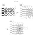
도 3은 도 2에 도시된 손가락 모드시 터치 센싱 방법의 일 예를 보여주는 도면이고, 도 4는 도 2에 도시된 펜 모드시 터치 센싱 방법의 일 예를 보여주는 도면이다.FIG. 3 is a diagram illustrating an example of a touch sensing method in the finger mode shown in FIG. 2, and FIG. 4 is a diagram illustrating an example of a touch sensing method in the pen mode shown in FIG. 2.
한편, 도 3 및 도 4에서는 설명의 편의상 다이아몬드 형태의 터치 전극을 일부만 도시하였으나, 본 발명은 이에 한정되지 않으며 설계 변경에 따라 다양한 형태, 크기 및 개수의 터치 전극이 가능할 수 있다.Meanwhile, in FIGS. 3 and 4, only a part of a diamond-shaped touch electrode is illustrated for convenience of description, but the present invention is not limited thereto, and various shapes, sizes, and numbers of touch electrodes may be possible according to a design change.
먼저, 핑거 모드(Finger Mode)인 경우 도 3에 도시된 바와 같이, S301에서 손가락 터치 인식을 위해 복수의 제2구동 전극인 홀수 번째 구동 전극(TX#1, TX#3, TX#5)으로 구동 펄스가 인가되면, S302에서와 홀수 번째 구동 전극에 인가된 구동 펄스에 의한 센싱 신호의 원시 데이터가 산출되며, S303에서 구동 펄스가 인가되지 않은 복수의 제2구동 전극에 대응되는 센싱 신호는 인접한 복수의 제1구동 전극에 대응되는 센싱 신호의 원시 데이터를 보간하여 산출될 수 있다. 예를 들어, 인접한 복수의 제1구동 전극의 원시 데이터를 이용하여 각각의 데이터를 보간하여 구동 펄스가 인가되지 않은 복수의 제2구동 전극에 대응되는 보간 데이터가 산출될 수 있다. 마지막으로, S304에서 원시 데이터 및 보간 데이터를 이용하여 핑거 모드에서의 터치 좌표가 추출될 수 있다. 한면, S303 및 S304와 다르게 복수의 제1구동 전극에 대응되는 센싱 신호의 원시 데이터만을 이용하여 터치 좌표가 추출될 수 있다.First, in the case of a finger mode, as shown in FIG. 3, in S301, a plurality of second driving electrodes, which are odd-numbered driving electrodes (TX#1, TX#3, TX#5), are used for finger touch recognition. When the driving pulse is applied, raw data of the sensing signal by the driving pulse applied to the odd-numbered driving electrode is calculated in S302, and the sensing signal corresponding to the plurality of second driving electrodes to which no driving pulse is applied in S303 is adjacent It may be calculated by interpolating raw data of sensing signals corresponding to a plurality of first driving electrodes. For example, by interpolating each data using raw data of a plurality of adjacent first driving electrodes, interpolation data corresponding to a plurality of second driving electrodes to which a driving pulse is not applied may be calculated. Finally, in S304, touch coordinates in the finger mode may be extracted using the raw data and the interpolated data. On the other hand, unlike S303 and S304, touch coordinates may be extracted using only raw data of sensing signals corresponding to a plurality of first driving electrodes.
다음으로, 펜 모드(Pen Mode)인 경우 도 4에 도시된 바와 같이, S401에서 펜 터치 인식을 위해 모든 구동 전극으로 구동 펄스가 인가되면, S402에서 펜 터치된 지점의 원시 데이터가 산출되며, S403에서 산출된 원시 데이터를 이용하여 펜 모드 에서의 터치 좌표가 추출 될 수 있다.Next, in the case of the pen mode, as shown in FIG. 4, when driving pulses are applied to all driving electrodes for pen touch recognition in S401, raw data of the point touched by the pen is calculated in S402, S403. Touch coordinates in the pen mode can be extracted using the raw data calculated in.
따라서, 본 발명의 실시예들에 따른 터치 스크린 장치는 손가락 터치 인식과 펜 터치 인식을 구분하여 구동하며, 손가락 터치 인식 시 모든 구동 전극으로 구동 펄스를 인가하지 않고 일부 구동 전극으로 구동 펄스를 인가함으로써 터치 패널로 인가되는 부하를 감소시켜 소비 전력을 저감할 수 있다.Therefore, the touch screen device according to the embodiments of the present invention is driven by dividing finger touch recognition and pen touch recognition, and when the finger touch is recognized, driving pulses are applied to some driving electrodes without applying driving pulses to all driving electrodes. Power consumption can be reduced by reducing the load applied to the touch panel.
한편, 위에서 설명한 본 발명의 터치 스크린 장치(10)는 다양한 종류의 디스플레이 패널과 결합하여 터치 스크린 표시장치를 구성할 수 있다.Meanwhile, the
한편, 이하에서는 본 발명의 실시예들에 따른 터치 스크린 표시장치에 대해 도면을 참조하여 설명하기로 한다.Meanwhile, hereinafter, a touch screen display device according to embodiments of the present invention will be described with reference to the drawings.
삭제delete
삭제delete
도 5 내지 도 7은 본 발명의 실시예들에 따른 터치 스크린 표시장치의 구성의 예들을 개략적으로 보여주는 도면이다.5 to 7 are diagrams schematically showing examples of the configuration of a touch screen display device according to embodiments of the present invention.
도 5 내지 도 7에 도시된 디스플레이 패널(20)은 액정표시장치 것으로 일 예를 들어 설명하기로 하며, 본 발명은 이에 한정되지 않고, 전계 방출 표시장치, 플라즈마 디스플레이 패널, 전계발광 표시장치, 전기영동 표시장치 등 다양한 표시장치에 적용될 수 있다. 또한, 액정표시장치의 일반적인 구성에 대한 설명은 생략하기로 한다.The
본 발명의 실시예들에 따른 터치 스크린 표시장치(1)는 도 5에 도시된 바와 같이, 디스플레이 패널(20)의 상부 편광판(POL1) 상에 터치 스크린 장치(10)의 터치 스크린 패널(100)이 위치하거나, 도 6에 도시된 바와 같이, 디스플레이 패널(20)의 상부 편광판(POL1)과 상부 기판(GLS1) 사이에 터치 스크린 장치(10)의 터치 스크린 패널(100)이 위치하거나, 도 7에 도시된 바와 같이, 터치 스크린 장치(10)의 터치 스크린 패널(100)이 디스플레이 패널(20)에 내장될 수 있다. 여기서, "GLS2"는 하부 기판, "POL2"는 하부 편광판을 각각 의미한다.As shown in FIG. 5, the touch
한편, 도 7에 도시된 터치 스크린 패널(100)에 포함된 복수의 구동 전극 및 복수의 센싱 전극 중 적어도 하나는 터치 전극의 기능 및 공통 전극의 기능을 함께 수행할 수 있다.Meanwhile, at least one of the plurality of driving electrodes and the plurality of sensing electrodes included in the
예를 들어, 복수의 구동 전극이 공통 전극 및 터치 전극의 기능을 수행하는 경우 복수의 센싱 전극은 터치 전극의 기능만을 수행하거나, 복수의 센싱 전극이 공통 전극 및 터치 전극의 기능을 수행하는 경우 복수의 구동 전극은 터치 전극의 기능만을 수행할 수 있다. 또한, 복수의 구동 전극 및 복수의 센싱 전극 모두 공통 전극 및 터치 전극의 기능을 수행할 수 있다.For example, when a plurality of driving electrodes perform the functions of a common electrode and a touch electrode, a plurality of sensing electrodes perform only the functions of a touch electrode, or a plurality of sensing electrodes perform the functions of a common electrode and a touch electrode. The driving electrode of can perform only the function of a touch electrode. In addition, all of the plurality of driving electrodes and the plurality of sensing electrodes may function as a common electrode and a touch electrode.
한편, 이하에서는 본 발명의 실시예들에 따는 터치 스크린 표시장치의 구동 방법을 도면을 참조하여 설명하기로 한다.Meanwhile, a method of driving a touch screen display device according to embodiments of the present invention will be described below with reference to the drawings.
삭제delete
도 8 및 도 9는 본 발명의 실시예들에 따른 터치 스크린 표시장치의 구동 방법의 예들을 보여주는 타이밍도이다.8 and 9 are timing diagrams illustrating examples of a method of driving a touch screen display device according to embodiments of the present invention.
한편, 도 8에 도시된 타이밍도는 도 5 및 도 6에 도시된 터치 스크린 표시장치의 타이밍도에 해당하며, 도 9에 도시된 타이밍도는 도 7에 도시된 터치 스크린 표시장치의 타이밍도에 해당할 수 있다.Meanwhile, the timing diagram illustrated in FIG. 8 corresponds to the timing diagram of the touch screen display device illustrated in FIGS. 5 and 6, and the timing diagram illustrated in FIG. 9 corresponds to the timing diagram of the touch screen display device illustrated in FIG. 7. May be applicable.
도 8에 도시된 타이밍도에 따는 터치 스크린 표시장치는 디스플레이 패널의 구동과 별도로 터치 여부를 감지하며, 이전 터치 센싱 구간의 터치 타입이 펜 터치인 것으로 인식된 경우에는 복수의 구동 전극(TX#1, TX#2, …, TX#m, 여기서 m은 홀수) 모두로 구동 펄스를 순차적으로 인가하는 펜 모드로 동작하며, 이전 터치 센싱 구간의 터치 타입이 손가락 터치인 것으로 인식된 경우에는 복수의 구동 전극(TX#1, TX#2, …, TX#m) 중 짝수 번째 구동 전극(TX#2, TX#4, TX#m-1)을 제외한 홀수 번째 구동 전극(TX#1, TX#3, …, TX#m)으로 구동 펄스를 순차적으로 인가하는 핑거 모드로 동작할 수 있다. 따라서, 핑거 모드의 경우 터치 응답 시간이 짧아지고 결과적으로 터치 응답 속도가 증가할 수 있다.The touch screen display device according to the timing diagram shown in FIG. 8 detects whether a touch is separately from driving the display panel, and when it is recognized that the touch type of the previous touch sensing period is a pen touch, a plurality of driving
도 9에 도시된 타이밍도에 따른 터치 스크린 표시장치는 디스플레이 패널에 터치 스크린 패널이 내장됨에 따라 매 프레임 마다 디스플레이 구동 및 터치 구동이 시분할 될 수 있다.In the touch screen display device according to the timing diagram illustrated in FIG. 9, since the touch screen panel is embedded in the display panel, display driving and touch driving may be time-divided in every frame.
터치 구동 시 도 8과 마찬가지로 이전 터치 센싱 구간의 터치 타입이 펜 터치인 것으로 인식된 경우에는 복수의 구동 전극(TX#1, TX#2, …, TX#m, 여기서 m은 홀수) 모두로 구동 펄스를 순차적으로 인가하는 펜 모드로 동작하며, 이전 터치 센싱 구간의 터치 타입이 손가락 터치인 것으로 인식된 경우에는 복수의 구동 전극(TX#1, TX#2, …, TX#m) 중 짝수 번째 구동 전극(TX#2, TX#4, TX#m-1)을 제외한 홀수 번째 구동 전극(TX#1, TX#3, …, TX#m)으로 구동 펄스를 순차적으로 인가하는 핑거 모드로 동작할 수 있다. 한편, 터치 구동 시 인식된 터치 타입이 손가락 터치이면, 계속해서 핑거 모드로 터치를 센싱하지만, 펜 터치이면 다음 프레임의 터치 구동 시 펜 모드로 터치를 센싱할 수 있다. 결과적으로 핑거 모드로 터치를 센싱하는 경우 일부 구동 전극으로 구동 펄스가 인가됨에 따라 소비 전력이 저감되고 터치 응답 시간이 감소하기 때문에 결과적으로 터치 응답 속도가 증가할 수 있다.When the touch is driven as in Fig. 8, when the touch type in the previous touch sensing section is recognized as a pen touch, all of the plurality of driving electrodes (
한편, 도 9에 도시된 타이밍도는 매 프레임마다 디스플레이 구동 및 터치 구동이 한 번씩 포함되는 것으로 도시되어 있으나, 본 발명은 이에 한정되지 않으며, 다른 실시예로 매 프레임마다 디스플레이 구동 및 터치 구동이 교번적으로 포함될 수 있다. 또한, 이 경우 디스플레이 구동의 개수 및 시간에 따라 디스플레이 구동 주파수를 60Hz, 120Hz, 240Hz 또는 그 이상으로 조정할 수 있으며, 터치 구동의 개수 및 시간에 따라 터치 리포트 레이트를 60Hz, 100Hz, 또는 그 이상으로 조정할 수 있다.Meanwhile, the timing diagram shown in FIG. 9 is shown that display driving and touch driving are included once per frame, but the present invention is not limited thereto, and as another embodiment, display driving and touch driving are alternately performed for each frame. Can be included as an enemy. Also, in this case, the display driving frequency can be adjusted to 60Hz, 120Hz, 240Hz or more according to the number and time of display driving, and the touch report rate can be adjusted to 60Hz, 100Hz, or more according to the number and time of touch driving. I can.
따라서, 본 발명의 실시예들에 따른 터치 스크린 장치는 손가락 터치 인식과 펜 터치 인식을 구분하여 구동하며, 손가락 터치 인식 시 모든 구동 전극으로 구동 펄스를 인가하지 않고 일부 구동 전극으로 구동 펄스를 인가함으로써 터치 패널로 인가되는 부하를 감소시켜 소비 전력을 저감할 수 있다.Therefore, the touch screen device according to the embodiments of the present invention is driven by dividing finger touch recognition and pen touch recognition, and when the finger touch is recognized, driving pulses are applied to some driving electrodes without applying driving pulses to all driving electrodes. Power consumption can be reduced by reducing the load applied to the touch panel.
본 발명이 속하는 기술분야의 당업자는 상술한 본 발명이 그 기술적 사상이나 필수적 특징을 변경하지 않고서 다른 구체적인 형태로 실시될 수 있다는 것을 이해할 수 있을 것이다.Those skilled in the art to which the present invention pertains will appreciate that the above-described present invention can be implemented in other specific forms without changing the technical spirit or essential features thereof.
그러므로, 이상에서 기술한 실시예들은 모든 면에서 예시적인 것이며 한정적인 것이 아닌 것으로 이해해야만 한다. 본 발명의 범위는 상기 상세한 설명보다는 후술하는 특허청구범위에 의하여 나타내어지며, 특허청구범위의 의미 및 범위 그리고 그 등가 개념으로부터 도출되는 모든 변경 또는 변형된 형태가 본 발명의 범위에 포함되는 것으로 해석되어야 한다.Therefore, it should be understood that the embodiments described above are illustrative in all respects and not limiting. The scope of the present invention is indicated by the claims to be described later rather than the detailed description, and all changes or modified forms derived from the meaning and scope of the claims and their equivalent concepts should be interpreted as being included in the scope of the present invention. do.
100 : 터치 스크린 패널200 : 터치 회로부
210 : 구동부220 : 센싱부100: touch screen panel 200: touch circuit unit
210: driving unit 220: sensing unit
Claims (12)
Translated fromKorean이전 터치 센싱 구간의 터치 타입이 손가락 터치이면, 상기 복수의 구동 전극 중 복수의 제1구동 전극을 제외한 복수의 제2구동 전극으로 구동 펄스를 순차적으로 인가하고, 상기 구동 펄스에 의한 센싱 신호를 상기 복수의 센싱 전극으로부터 수신하는 터치 회로부를 포함하며,
상기 터치 회로부는,
상기 이전 터치 센싱 구간의 터치 타입이 펜 터치이면, 상기 복수의 구동 전극으로 상기 구동 펄스를 순차적으로 인가하는, 터치 스크린 장치.A touch screen panel including a plurality of driving electrodes disposed parallel in a first direction and a plurality of sensing electrodes disposed parallel in a second direction; And
If the touch type of the previous touch sensing period is a finger touch, driving pulses are sequentially applied to a plurality of second driving electrodes excluding a plurality of first driving electrodes among the plurality of driving electrodes, and a sensing signal by the driving pulse Including a touch circuit receiving from a plurality of sensing electrodes,
The touch circuit unit,
When the touch type of the previous touch sensing period is a pen touch, the driving pulse is sequentially applied to the plurality of driving electrodes.
상기 복수의 제1구동 전극은 짝수 번째 구동 전극이며, 상기 복수의 제2구동 전극은 홀수 번째 구동 전극인, 터치 스크린 장치.The method of claim 1,
The plurality of first driving electrodes are even-numbered driving electrodes, and the plurality of second driving electrodes are odd-numbered driving electrodes.
상기 복수의 제1구동 전극은 홀수 번째 구동 전극이며, 상기 복수의 제2구동 전극은 짝수 번째 구동 전극인, 터치 스크린 장치.The method of claim 1,
The plurality of first driving electrodes are odd-numbered driving electrodes, and the plurality of second driving electrodes are even-numbered driving electrodes.
상기 복수의 제1구동 전극 중 적어도 두 전극은 상기 복수의 제2구동 전극 중 적어도 하나를 사이에 두고 각각 위치하는, 터치 스크린 장치.The method of claim 1,
At least two of the plurality of first driving electrodes are each positioned with at least one of the plurality of second driving electrodes interposed therebetween.
상기 터치 회로부는,
상기 복수의 제2구동 전극으로 순차적으로 인가한 상기 구동 펄스에 의한 터치 타입이 손가락 터치이면, 다음 터치 센싱 구간에서 상기 복수의 제2구동 전극을 제외한 상기 복수의 제1구동 전극으로 상기 구동 펄스를 순차적으로 인가하는, 터치 스크린 장치.The method of claim 1,
The touch circuit unit,
If the touch type by the driving pulses sequentially applied to the plurality of second driving electrodes is a finger touch, the driving pulses are applied to the plurality of first driving electrodes excluding the plurality of second driving electrodes in a next touch sensing section. A touch screen device that is sequentially applied.
상기 터치 회로부는,
상기 복수의 제2구동 전극에 대응되는 센싱 신호의 원시 데이터를 이용하여 상기 복수의 제1구동 전극에 대응되는 센싱 신호의 보간 데이터를 산출하는, 터치 스크린 장치.The method of claim 1,
The touch circuit unit,
A touch screen device configured to calculate interpolated data of sensing signals corresponding to the plurality of first driving electrodes by using raw data of sensing signals corresponding to the plurality of second driving electrodes.
상기 보간 데이터는 상기 복수의 제1구동 전극 각각에 인접한 상기 복수의 제2구동 전극에 대응되는 상기 원시 데이터를 보간하여 산출되는, 터치 스크린 장치.The method of claim 7,
The interpolation data is calculated by interpolating the raw data corresponding to the plurality of second driving electrodes adjacent to each of the plurality of first driving electrodes.
상기 터치 스크린 장치의 상기 터치 스크린 패널 상에 위치하는 디스플레이 패널을 포함하는 터치 스크린 표시장치.The touch screen device according to any one of claims 1 and 3 to 8; And
A touch screen display device comprising a display panel positioned on the touch screen panel of the touch screen device.
상기 터치 스크린 장치의 상기 터치 스크린 패널이 내장된 디스플레이 패널을 포함하며,
상기 복수의 제1구동 전극 및 상기 복수의 제2구동 전극 중 적어도 하나는 터치 전극의 기능 및 공통 전극의 기능을 함께 수행하는, 터치 스크린 표시장치.The touch screen device according to any one of claims 1 and 3 to 8; And
And a display panel in which the touch screen panel of the touch screen device is embedded,
At least one of the plurality of first driving electrodes and the plurality of second driving electrodes simultaneously performs a function of a touch electrode and a function of a common electrode.
이전 터치 센싱 구간의 터치 타입이 손가락 터치이면, 상기 복수의 구동 전극 중 복수의 제1구동 전극을 제외한 복수의 제2구동 전극으로 구동 펄스를 순차적으로 인가하는 단계; 및
상기 복수의 제2구동 전극으로 인가한 상기 구동 펄스에 의한 센싱 신호를 수신하는 단계를 포함하며,
상기 이전 터치 센싱 구간의 터치 타입이 펜 터치이면, 상기 복수의 구동 전극으로 상기 구동 펄스를 순차적으로 인가하는 단계; 및
상기 복수의 구동 전극 모두에 인가된 상기 구동 펄스에 의한 센싱 신호를 상기 복수의 센싱 전극으로부터 수신하는 단계를 포함하는 터치 스크린 장치 구동 방법.In the driving method of a touch screen device including a touch screen panel and a touch circuit unit including a plurality of driving electrodes disposed in parallel in a first direction and a plurality of sensing electrodes disposed in parallel in a second direction,
If the touch type of the previous touch sensing period is a finger touch, sequentially applying driving pulses to a plurality of second driving electrodes excluding a plurality of first driving electrodes among the plurality of driving electrodes; And
And receiving a sensing signal by the driving pulse applied to the plurality of second driving electrodes,
If the touch type of the previous touch sensing period is a pen touch, sequentially applying the driving pulses to the plurality of driving electrodes; And
And receiving a sensing signal by the driving pulse applied to all of the plurality of driving electrodes from the plurality of sensing electrodes.
Priority Applications (4)
| Application Number | Priority Date | Filing Date | Title |
|---|---|---|---|
| KR1020130169110AKR102192521B1 (en) | 2013-12-31 | 2013-12-31 | Touch screen device, touch screen display device using the same and method for driving thereof |
| US14/551,550US9354693B2 (en) | 2013-12-31 | 2014-11-24 | Touch screen device, touch screen display device using the same, and driving method thereof |
| CN201410805058.3ACN104750338A (en) | 2013-12-31 | 2014-12-19 | Touch screen device, touch screen display device using the same, and driving method thereof |
| US15/143,375US9703441B2 (en) | 2013-12-31 | 2016-04-29 | Touch screen device, touch screen display device using the same, and driving method thereof |
Applications Claiming Priority (1)
| Application Number | Priority Date | Filing Date | Title |
|---|---|---|---|
| KR1020130169110AKR102192521B1 (en) | 2013-12-31 | 2013-12-31 | Touch screen device, touch screen display device using the same and method for driving thereof |
Publications (2)
| Publication Number | Publication Date |
|---|---|
| KR20150079104A KR20150079104A (en) | 2015-07-08 |
| KR102192521B1true KR102192521B1 (en) | 2020-12-17 |
Family
ID=53481662
Family Applications (1)
| Application Number | Title | Priority Date | Filing Date |
|---|---|---|---|
| KR1020130169110AActiveKR102192521B1 (en) | 2013-12-31 | 2013-12-31 | Touch screen device, touch screen display device using the same and method for driving thereof |
Country Status (3)
| Country | Link |
|---|---|
| US (2) | US9354693B2 (en) |
| KR (1) | KR102192521B1 (en) |
| CN (1) | CN104750338A (en) |
Families Citing this family (11)
| Publication number | Priority date | Publication date | Assignee | Title |
|---|---|---|---|---|
| CN105549782B (en)* | 2015-12-14 | 2018-05-08 | 厦门天马微电子有限公司 | Touch device and touch control display apparatus |
| CN105700745A (en)* | 2016-01-08 | 2016-06-22 | 京东方科技集团股份有限公司 | Array substrate and manufacturing method thereof, driving mode, touch screen and display device |
| US10474286B2 (en)* | 2016-10-25 | 2019-11-12 | Lg Display Co., Ltd. | Touch display device, active pen, touch system, touch circuit, and pen recognition method |
| KR102656423B1 (en) | 2016-12-30 | 2024-04-09 | 엘지디스플레이 주식회사 | Touch sensing system and display device including the same |
| CN108733233A (en)* | 2017-04-13 | 2018-11-02 | 瑞鼎科技股份有限公司 | Active pen signal identification method applied to capacitive touch panel |
| TWI609310B (en)* | 2017-04-27 | 2017-12-21 | 義隆電子股份有限公司 | Method For Sensing A Stylus On A Display Device And Device For Sensing A Stylus |
| TWI652605B (en) | 2017-05-08 | 2019-03-01 | 義隆電子股份有限公司 | In-cell touch display device and communicating method thereof with an active stylus thereof |
| US10712884B2 (en)* | 2017-10-03 | 2020-07-14 | Microsoft Technology Licensing, Llc | Touch sensor locating mode |
| KR102553530B1 (en)* | 2018-07-20 | 2023-07-10 | 엘지디스플레이 주식회사 | Touch display panel, touch display device and method for driving thereof |
| CN110928449B (en)* | 2019-11-26 | 2023-06-23 | 北京集创北方科技股份有限公司 | Point reporting method and device of touch screen, electronic equipment and storage medium |
| WO2023090094A1 (en)* | 2021-11-16 | 2023-05-25 | パナソニックIpマネジメント株式会社 | Display system and control device |
Citations (1)
| Publication number | Priority date | Publication date | Assignee | Title |
|---|---|---|---|---|
| US20130278560A1 (en)* | 2010-12-28 | 2013-10-24 | Yoshiyuki Yamaguchi | Input device, input control method, program and electronic apparatus |
Family Cites Families (7)
| Publication number | Priority date | Publication date | Assignee | Title |
|---|---|---|---|---|
| WO2009007704A1 (en) | 2007-07-12 | 2009-01-15 | Qrg Limited | Two-dimensional touch panel |
| US8482545B2 (en)* | 2008-10-02 | 2013-07-09 | Wacom Co., Ltd. | Combination touch and transducer input system and method |
| JP2012103797A (en)* | 2010-11-08 | 2012-05-31 | Sony Corp | Input device, coordinate detection method and program |
| KR101219273B1 (en)* | 2011-01-14 | 2013-01-08 | 삼성디스플레이 주식회사 | touch screen system |
| KR101461157B1 (en)* | 2011-04-18 | 2014-11-13 | 삼성디스플레이 주식회사 | touch screen system and driving method thereof |
| KR101898979B1 (en) | 2012-02-16 | 2018-09-17 | 삼성디스플레이 주식회사 | Method of operating a touch panel, touch panel and display device |
| CN103207718B (en)* | 2013-03-18 | 2016-08-03 | 敦泰科技有限公司 | A kind of mutual capacitance type touch screen and touch sensible method thereof |
- 2013
- 2013-12-31KRKR1020130169110Apatent/KR102192521B1/enactiveActive
- 2014
- 2014-11-24USUS14/551,550patent/US9354693B2/enactiveActive
- 2014-12-19CNCN201410805058.3Apatent/CN104750338A/enactivePending
- 2016
- 2016-04-29USUS15/143,375patent/US9703441B2/enactiveActive
Patent Citations (1)
| Publication number | Priority date | Publication date | Assignee | Title |
|---|---|---|---|---|
| US20130278560A1 (en)* | 2010-12-28 | 2013-10-24 | Yoshiyuki Yamaguchi | Input device, input control method, program and electronic apparatus |
Also Published As
| Publication number | Publication date |
|---|---|
| CN104750338A (en) | 2015-07-01 |
| US9703441B2 (en) | 2017-07-11 |
| US20160246414A1 (en) | 2016-08-25 |
| US20150185810A1 (en) | 2015-07-02 |
| KR20150079104A (en) | 2015-07-08 |
| US9354693B2 (en) | 2016-05-31 |
Similar Documents
| Publication | Publication Date | Title |
|---|---|---|
| KR102192521B1 (en) | Touch screen device, touch screen display device using the same and method for driving thereof | |
| KR102081606B1 (en) | Touch ic and display device integrated with touch screen using the same | |
| KR101364075B1 (en) | Display device with integrated touch screen | |
| JP5685512B2 (en) | Display device, touch detection device, driving method, and electronic device | |
| CN106598334B (en) | Touch display device and driving method thereof | |
| JP5840510B2 (en) | Display panel and display panel driving method | |
| US10365755B2 (en) | Display device with touch detection function and display method | |
| US20150199060A1 (en) | Liquid crystal display device | |
| KR102078650B1 (en) | Touch ic and touch screen display device using the same | |
| US20150277657A1 (en) | Touch drive device, touch detection device and display device having touch detection function | |
| KR102044551B1 (en) | Touch sensing apparatus and driving method thereof | |
| KR20150002242A (en) | Display device and method of driving the same | |
| US10296156B2 (en) | Touch detection device, display device with touch detecting function, and electronic apparatus | |
| KR102133736B1 (en) | Display device with integrated touch screen and method for driving the same | |
| KR102286893B1 (en) | Touch Display Device | |
| JP2014199499A (en) | Electronic device and control method of electronic device | |
| CN109032409A (en) | A kind of driving method of display panel, display panel and display device | |
| TW201629716A (en) | In-cell touch display device and method for driving same | |
| KR102146678B1 (en) | Touch screen device and touch screen display device using the same | |
| US20200371626A1 (en) | Pressure-sensor-embedded display | |
| KR20170138160A (en) | Display apparatus | |
| KR102799985B1 (en) | Touch display device, touch circuit, and touch driving method thereof | |
| CN104508736A (en) | Liquid crystal display device | |
| KR102259238B1 (en) | Driving Apparatus Of Touch Panel | |
| KR102177901B1 (en) | Display device with integrated touch screen |
Legal Events
| Date | Code | Title | Description |
|---|---|---|---|
| PA0109 | Patent application | Patent event code:PA01091R01D Comment text:Patent Application Patent event date:20131231 | |
| PG1501 | Laying open of application | ||
| A201 | Request for examination | ||
| PA0201 | Request for examination | Patent event code:PA02012R01D Patent event date:20181212 Comment text:Request for Examination of Application Patent event code:PA02011R01I Patent event date:20131231 Comment text:Patent Application | |
| E902 | Notification of reason for refusal | ||
| PE0902 | Notice of grounds for rejection | Comment text:Notification of reason for refusal Patent event date:20200601 Patent event code:PE09021S01D | |
| E701 | Decision to grant or registration of patent right | ||
| PE0701 | Decision of registration | Patent event code:PE07011S01D Comment text:Decision to Grant Registration Patent event date:20201130 | |
| PR0701 | Registration of establishment | Comment text:Registration of Establishment Patent event date:20201211 Patent event code:PR07011E01D | |
| PR1002 | Payment of registration fee | Payment date:20201211 End annual number:3 Start annual number:1 | |
| PG1601 | Publication of registration | ||
| PR1001 | Payment of annual fee | Payment date:20231115 Start annual number:4 End annual number:4 | |
| PR1001 | Payment of annual fee | Payment date:20241118 Start annual number:5 End annual number:5 |