KR102191538B1 - Charging system, charging method and power adapter for terminal - Google Patents
Charging system, charging method and power adapter for terminalDownload PDFInfo
- Publication number
- KR102191538B1 KR102191538B1KR1020177030961AKR20177030961AKR102191538B1KR 102191538 B1KR102191538 B1KR 102191538B1KR 1020177030961 AKR1020177030961 AKR 1020177030961AKR 20177030961 AKR20177030961 AKR 20177030961AKR 102191538 B1KR102191538 B1KR 102191538B1
- Authority
- KR
- South Korea
- Prior art keywords
- charging
- voltage
- terminal
- power adapter
- command
- Prior art date
- Legal status (The legal status is an assumption and is not a legal conclusion. Google has not performed a legal analysis and makes no representation as to the accuracy of the status listed.)
- Expired - Fee Related
Links
Images


Classifications
- H—ELECTRICITY
- H04—ELECTRIC COMMUNICATION TECHNIQUE
- H04M—TELEPHONIC COMMUNICATION
- H04M19/00—Current supply arrangements for telephone systems
- H—ELECTRICITY
- H02—GENERATION; CONVERSION OR DISTRIBUTION OF ELECTRIC POWER
- H02J—CIRCUIT ARRANGEMENTS OR SYSTEMS FOR SUPPLYING OR DISTRIBUTING ELECTRIC POWER; SYSTEMS FOR STORING ELECTRIC ENERGY
- H02J7/00—Circuit arrangements for charging or depolarising batteries or for supplying loads from batteries
- H02J7/007—Regulation of charging or discharging current or voltage
- H—ELECTRICITY
- H02—GENERATION; CONVERSION OR DISTRIBUTION OF ELECTRIC POWER
- H02J—CIRCUIT ARRANGEMENTS OR SYSTEMS FOR SUPPLYING OR DISTRIBUTING ELECTRIC POWER; SYSTEMS FOR STORING ELECTRIC ENERGY
- H02J7/00—Circuit arrangements for charging or depolarising batteries or for supplying loads from batteries
- H02J7/02—Circuit arrangements for charging or depolarising batteries or for supplying loads from batteries for charging batteries from AC mains by converters
- G—PHYSICS
- G01—MEASURING; TESTING
- G01R—MEASURING ELECTRIC VARIABLES; MEASURING MAGNETIC VARIABLES
- G01R31/00—Arrangements for testing electric properties; Arrangements for locating electric faults; Arrangements for electrical testing characterised by what is being tested not provided for elsewhere
- G01R31/28—Testing of electronic circuits, e.g. by signal tracer
- G01R31/2851—Testing of integrated circuits [IC]
- G01R31/2855—Environmental, reliability or burn-in testing
- G01R31/2872—Environmental, reliability or burn-in testing related to electrical or environmental aspects, e.g. temperature, humidity, vibration, nuclear radiation
- G01R31/2874—Environmental, reliability or burn-in testing related to electrical or environmental aspects, e.g. temperature, humidity, vibration, nuclear radiation related to temperature
- H—ELECTRICITY
- H01—ELECTRIC ELEMENTS
- H01F—MAGNETS; INDUCTANCES; TRANSFORMERS; SELECTION OF MATERIALS FOR THEIR MAGNETIC PROPERTIES
- H01F27/00—Details of transformers or inductances, in general
- H01F27/42—Circuits specially adapted for the purpose of modifying, or compensating for, electric characteristics of transformers, reactors, or choke coils
- H01F27/422—Circuits specially adapted for the purpose of modifying, or compensating for, electric characteristics of transformers, reactors, or choke coils for instrument transformers
- H01F27/425—Circuits specially adapted for the purpose of modifying, or compensating for, electric characteristics of transformers, reactors, or choke coils for instrument transformers for voltage transformers
- H—ELECTRICITY
- H01—ELECTRIC ELEMENTS
- H01M—PROCESSES OR MEANS, e.g. BATTERIES, FOR THE DIRECT CONVERSION OF CHEMICAL ENERGY INTO ELECTRICAL ENERGY
- H01M10/00—Secondary cells; Manufacture thereof
- H01M10/05—Accumulators with non-aqueous electrolyte
- H01M10/052—Li-accumulators
- H01M10/0525—Rocking-chair batteries, i.e. batteries with lithium insertion or intercalation in both electrodes; Lithium-ion batteries
- H—ELECTRICITY
- H02—GENERATION; CONVERSION OR DISTRIBUTION OF ELECTRIC POWER
- H02H—EMERGENCY PROTECTIVE CIRCUIT ARRANGEMENTS
- H02H3/00—Emergency protective circuit arrangements for automatic disconnection directly responsive to an undesired change from normal electric working condition with or without subsequent reconnection ; integrated protection
- H02H3/20—Emergency protective circuit arrangements for automatic disconnection directly responsive to an undesired change from normal electric working condition with or without subsequent reconnection ; integrated protection responsive to excess voltage
- H02H3/202—Emergency protective circuit arrangements for automatic disconnection directly responsive to an undesired change from normal electric working condition with or without subsequent reconnection ; integrated protection responsive to excess voltage for DC systems
- H—ELECTRICITY
- H02—GENERATION; CONVERSION OR DISTRIBUTION OF ELECTRIC POWER
- H02H—EMERGENCY PROTECTIVE CIRCUIT ARRANGEMENTS
- H02H7/00—Emergency protective circuit arrangements specially adapted for specific types of electric machines or apparatus or for sectionalised protection of cable or line systems, and effecting automatic switching in the event of an undesired change from normal working conditions
- H02H7/18—Emergency protective circuit arrangements specially adapted for specific types of electric machines or apparatus or for sectionalised protection of cable or line systems, and effecting automatic switching in the event of an undesired change from normal working conditions for batteries; for accumulators
- H—ELECTRICITY
- H02—GENERATION; CONVERSION OR DISTRIBUTION OF ELECTRIC POWER
- H02J—CIRCUIT ARRANGEMENTS OR SYSTEMS FOR SUPPLYING OR DISTRIBUTING ELECTRIC POWER; SYSTEMS FOR STORING ELECTRIC ENERGY
- H02J7/00—Circuit arrangements for charging or depolarising batteries or for supplying loads from batteries
- H02J7/00032—Circuit arrangements for charging or depolarising batteries or for supplying loads from batteries characterised by data exchange
- H02J7/00034—Charger exchanging data with an electronic device, i.e. telephone, whose internal battery is under charge
- H—ELECTRICITY
- H02—GENERATION; CONVERSION OR DISTRIBUTION OF ELECTRIC POWER
- H02J—CIRCUIT ARRANGEMENTS OR SYSTEMS FOR SUPPLYING OR DISTRIBUTING ELECTRIC POWER; SYSTEMS FOR STORING ELECTRIC ENERGY
- H02J7/00—Circuit arrangements for charging or depolarising batteries or for supplying loads from batteries
- H02J7/00032—Circuit arrangements for charging or depolarising batteries or for supplying loads from batteries characterised by data exchange
- H02J7/00036—Charger exchanging data with battery
- H—ELECTRICITY
- H02—GENERATION; CONVERSION OR DISTRIBUTION OF ELECTRIC POWER
- H02J—CIRCUIT ARRANGEMENTS OR SYSTEMS FOR SUPPLYING OR DISTRIBUTING ELECTRIC POWER; SYSTEMS FOR STORING ELECTRIC ENERGY
- H02J7/00—Circuit arrangements for charging or depolarising batteries or for supplying loads from batteries
- H02J7/00032—Circuit arrangements for charging or depolarising batteries or for supplying loads from batteries characterised by data exchange
- H02J7/00038—Circuit arrangements for charging or depolarising batteries or for supplying loads from batteries characterised by data exchange using passive battery identification means, e.g. resistors or capacitors
- H02J7/00043—Circuit arrangements for charging or depolarising batteries or for supplying loads from batteries characterised by data exchange using passive battery identification means, e.g. resistors or capacitors using switches, contacts or markings, e.g. optical, magnetic or barcode
- H—ELECTRICITY
- H02—GENERATION; CONVERSION OR DISTRIBUTION OF ELECTRIC POWER
- H02J—CIRCUIT ARRANGEMENTS OR SYSTEMS FOR SUPPLYING OR DISTRIBUTING ELECTRIC POWER; SYSTEMS FOR STORING ELECTRIC ENERGY
- H02J7/00—Circuit arrangements for charging or depolarising batteries or for supplying loads from batteries
- H02J7/0013—Circuit arrangements for charging or depolarising batteries or for supplying loads from batteries acting upon several batteries simultaneously or sequentially
- H—ELECTRICITY
- H02—GENERATION; CONVERSION OR DISTRIBUTION OF ELECTRIC POWER
- H02J—CIRCUIT ARRANGEMENTS OR SYSTEMS FOR SUPPLYING OR DISTRIBUTING ELECTRIC POWER; SYSTEMS FOR STORING ELECTRIC ENERGY
- H02J7/00—Circuit arrangements for charging or depolarising batteries or for supplying loads from batteries
- H02J7/0029—Circuit arrangements for charging or depolarising batteries or for supplying loads from batteries with safety or protection devices or circuits
- H02J7/0031—Circuit arrangements for charging or depolarising batteries or for supplying loads from batteries with safety or protection devices or circuits using battery or load disconnect circuits
- H—ELECTRICITY
- H02—GENERATION; CONVERSION OR DISTRIBUTION OF ELECTRIC POWER
- H02J—CIRCUIT ARRANGEMENTS OR SYSTEMS FOR SUPPLYING OR DISTRIBUTING ELECTRIC POWER; SYSTEMS FOR STORING ELECTRIC ENERGY
- H02J7/00—Circuit arrangements for charging or depolarising batteries or for supplying loads from batteries
- H02J7/0042—Circuit arrangements for charging or depolarising batteries or for supplying loads from batteries characterised by the mechanical construction
- H02J7/0044—Circuit arrangements for charging or depolarising batteries or for supplying loads from batteries characterised by the mechanical construction specially adapted for holding portable devices containing batteries
- H—ELECTRICITY
- H02—GENERATION; CONVERSION OR DISTRIBUTION OF ELECTRIC POWER
- H02J—CIRCUIT ARRANGEMENTS OR SYSTEMS FOR SUPPLYING OR DISTRIBUTING ELECTRIC POWER; SYSTEMS FOR STORING ELECTRIC ENERGY
- H02J7/00—Circuit arrangements for charging or depolarising batteries or for supplying loads from batteries
- H02J7/0042—Circuit arrangements for charging or depolarising batteries or for supplying loads from batteries characterised by the mechanical construction
- H02J7/0045—Circuit arrangements for charging or depolarising batteries or for supplying loads from batteries characterised by the mechanical construction concerning the insertion or the connection of the batteries
- H—ELECTRICITY
- H02—GENERATION; CONVERSION OR DISTRIBUTION OF ELECTRIC POWER
- H02J—CIRCUIT ARRANGEMENTS OR SYSTEMS FOR SUPPLYING OR DISTRIBUTING ELECTRIC POWER; SYSTEMS FOR STORING ELECTRIC ENERGY
- H02J7/00—Circuit arrangements for charging or depolarising batteries or for supplying loads from batteries
- H02J7/0047—Circuit arrangements for charging or depolarising batteries or for supplying loads from batteries with monitoring or indicating devices or circuits
- H—ELECTRICITY
- H02—GENERATION; CONVERSION OR DISTRIBUTION OF ELECTRIC POWER
- H02J—CIRCUIT ARRANGEMENTS OR SYSTEMS FOR SUPPLYING OR DISTRIBUTING ELECTRIC POWER; SYSTEMS FOR STORING ELECTRIC ENERGY
- H02J7/00—Circuit arrangements for charging or depolarising batteries or for supplying loads from batteries
- H02J7/007—Regulation of charging or discharging current or voltage
- H02J7/0071—Regulation of charging or discharging current or voltage with a programmable schedule
- H—ELECTRICITY
- H02—GENERATION; CONVERSION OR DISTRIBUTION OF ELECTRIC POWER
- H02J—CIRCUIT ARRANGEMENTS OR SYSTEMS FOR SUPPLYING OR DISTRIBUTING ELECTRIC POWER; SYSTEMS FOR STORING ELECTRIC ENERGY
- H02J7/00—Circuit arrangements for charging or depolarising batteries or for supplying loads from batteries
- H02J7/007—Regulation of charging or discharging current or voltage
- H02J7/00711—Regulation of charging or discharging current or voltage with introduction of pulses during the charging process
- H—ELECTRICITY
- H02—GENERATION; CONVERSION OR DISTRIBUTION OF ELECTRIC POWER
- H02J—CIRCUIT ARRANGEMENTS OR SYSTEMS FOR SUPPLYING OR DISTRIBUTING ELECTRIC POWER; SYSTEMS FOR STORING ELECTRIC ENERGY
- H02J7/00—Circuit arrangements for charging or depolarising batteries or for supplying loads from batteries
- H02J7/007—Regulation of charging or discharging current or voltage
- H02J7/00712—Regulation of charging or discharging current or voltage the cycle being controlled or terminated in response to electric parameters
- H02J7/00714—Regulation of charging or discharging current or voltage the cycle being controlled or terminated in response to electric parameters in response to battery charging or discharging current
- H—ELECTRICITY
- H02—GENERATION; CONVERSION OR DISTRIBUTION OF ELECTRIC POWER
- H02J—CIRCUIT ARRANGEMENTS OR SYSTEMS FOR SUPPLYING OR DISTRIBUTING ELECTRIC POWER; SYSTEMS FOR STORING ELECTRIC ENERGY
- H02J7/00—Circuit arrangements for charging or depolarising batteries or for supplying loads from batteries
- H02J7/007—Regulation of charging or discharging current or voltage
- H02J7/00712—Regulation of charging or discharging current or voltage the cycle being controlled or terminated in response to electric parameters
- H02J7/007182—Regulation of charging or discharging current or voltage the cycle being controlled or terminated in response to electric parameters in response to battery voltage
- H—ELECTRICITY
- H02—GENERATION; CONVERSION OR DISTRIBUTION OF ELECTRIC POWER
- H02J—CIRCUIT ARRANGEMENTS OR SYSTEMS FOR SUPPLYING OR DISTRIBUTING ELECTRIC POWER; SYSTEMS FOR STORING ELECTRIC ENERGY
- H02J7/00—Circuit arrangements for charging or depolarising batteries or for supplying loads from batteries
- H02J7/007—Regulation of charging or discharging current or voltage
- H02J7/007188—Regulation of charging or discharging current or voltage the charge cycle being controlled or terminated in response to non-electric parameters
- H02J7/007192—Regulation of charging or discharging current or voltage the charge cycle being controlled or terminated in response to non-electric parameters in response to temperature
- H—ELECTRICITY
- H02—GENERATION; CONVERSION OR DISTRIBUTION OF ELECTRIC POWER
- H02J—CIRCUIT ARRANGEMENTS OR SYSTEMS FOR SUPPLYING OR DISTRIBUTING ELECTRIC POWER; SYSTEMS FOR STORING ELECTRIC ENERGY
- H02J7/00—Circuit arrangements for charging or depolarising batteries or for supplying loads from batteries
- H02J7/02—Circuit arrangements for charging or depolarising batteries or for supplying loads from batteries for charging batteries from AC mains by converters
- H02J7/04—Regulation of charging current or voltage
- H02J7/06—Regulation of charging current or voltage using discharge tubes or semiconductor devices
- H—ELECTRICITY
- H02—GENERATION; CONVERSION OR DISTRIBUTION OF ELECTRIC POWER
- H02J—CIRCUIT ARRANGEMENTS OR SYSTEMS FOR SUPPLYING OR DISTRIBUTING ELECTRIC POWER; SYSTEMS FOR STORING ELECTRIC ENERGY
- H02J7/00—Circuit arrangements for charging or depolarising batteries or for supplying loads from batteries
- H02J7/14—Circuit arrangements for charging or depolarising batteries or for supplying loads from batteries for charging batteries from dynamo-electric generators driven at varying speed, e.g. on vehicle
- H02J7/1469—Regulation of the charging current or voltage otherwise than by variation of field
- H02J7/1492—Regulation of the charging current or voltage otherwise than by variation of field by means of controlling devices between the generator output and the battery
- H—ELECTRICITY
- H02—GENERATION; CONVERSION OR DISTRIBUTION OF ELECTRIC POWER
- H02J—CIRCUIT ARRANGEMENTS OR SYSTEMS FOR SUPPLYING OR DISTRIBUTING ELECTRIC POWER; SYSTEMS FOR STORING ELECTRIC ENERGY
- H02J7/00—Circuit arrangements for charging or depolarising batteries or for supplying loads from batteries
- H02J7/14—Circuit arrangements for charging or depolarising batteries or for supplying loads from batteries for charging batteries from dynamo-electric generators driven at varying speed, e.g. on vehicle
- H02J7/16—Regulation of the charging current or voltage by variation of field
- H02J7/24—Regulation of the charging current or voltage by variation of field using discharge tubes or semiconductor devices
- H02J7/2434—Regulation of the charging current or voltage by variation of field using discharge tubes or semiconductor devices with pulse modulation
- H—ELECTRICITY
- H02—GENERATION; CONVERSION OR DISTRIBUTION OF ELECTRIC POWER
- H02M—APPARATUS FOR CONVERSION BETWEEN AC AND AC, BETWEEN AC AND DC, OR BETWEEN DC AND DC, AND FOR USE WITH MAINS OR SIMILAR POWER SUPPLY SYSTEMS; CONVERSION OF DC OR AC INPUT POWER INTO SURGE OUTPUT POWER; CONTROL OR REGULATION THEREOF
- H02M1/00—Details of apparatus for conversion
- H02M1/08—Circuits specially adapted for the generation of control voltages for semiconductor devices incorporated in static converters
- H—ELECTRICITY
- H02—GENERATION; CONVERSION OR DISTRIBUTION OF ELECTRIC POWER
- H02M—APPARATUS FOR CONVERSION BETWEEN AC AND AC, BETWEEN AC AND DC, OR BETWEEN DC AND DC, AND FOR USE WITH MAINS OR SIMILAR POWER SUPPLY SYSTEMS; CONVERSION OF DC OR AC INPUT POWER INTO SURGE OUTPUT POWER; CONTROL OR REGULATION THEREOF
- H02M3/00—Conversion of DC power input into DC power output
- H02M3/02—Conversion of DC power input into DC power output without intermediate conversion into AC
- H02M3/04—Conversion of DC power input into DC power output without intermediate conversion into AC by static converters
- H02M3/10—Conversion of DC power input into DC power output without intermediate conversion into AC by static converters using discharge tubes with control electrode or semiconductor devices with control electrode
- H02M3/145—Conversion of DC power input into DC power output without intermediate conversion into AC by static converters using discharge tubes with control electrode or semiconductor devices with control electrode using devices of a triode or transistor type requiring continuous application of a control signal
- H02M3/155—Conversion of DC power input into DC power output without intermediate conversion into AC by static converters using discharge tubes with control electrode or semiconductor devices with control electrode using devices of a triode or transistor type requiring continuous application of a control signal using semiconductor devices only
- H02M3/156—Conversion of DC power input into DC power output without intermediate conversion into AC by static converters using discharge tubes with control electrode or semiconductor devices with control electrode using devices of a triode or transistor type requiring continuous application of a control signal using semiconductor devices only with automatic control of output voltage or current, e.g. switching regulators
- H—ELECTRICITY
- H02—GENERATION; CONVERSION OR DISTRIBUTION OF ELECTRIC POWER
- H02M—APPARATUS FOR CONVERSION BETWEEN AC AND AC, BETWEEN AC AND DC, OR BETWEEN DC AND DC, AND FOR USE WITH MAINS OR SIMILAR POWER SUPPLY SYSTEMS; CONVERSION OF DC OR AC INPUT POWER INTO SURGE OUTPUT POWER; CONTROL OR REGULATION THEREOF
- H02M3/00—Conversion of DC power input into DC power output
- H02M3/22—Conversion of DC power input into DC power output with intermediate conversion into AC
- H02M3/24—Conversion of DC power input into DC power output with intermediate conversion into AC by static converters
- H02M3/28—Conversion of DC power input into DC power output with intermediate conversion into AC by static converters using discharge tubes with control electrode or semiconductor devices with control electrode to produce the intermediate AC
- H02M3/325—Conversion of DC power input into DC power output with intermediate conversion into AC by static converters using discharge tubes with control electrode or semiconductor devices with control electrode to produce the intermediate AC using devices of a triode or a transistor type requiring continuous application of a control signal
- H02M3/335—Conversion of DC power input into DC power output with intermediate conversion into AC by static converters using discharge tubes with control electrode or semiconductor devices with control electrode to produce the intermediate AC using devices of a triode or a transistor type requiring continuous application of a control signal using semiconductor devices only
- H02M3/33507—Conversion of DC power input into DC power output with intermediate conversion into AC by static converters using discharge tubes with control electrode or semiconductor devices with control electrode to produce the intermediate AC using devices of a triode or a transistor type requiring continuous application of a control signal using semiconductor devices only with automatic control of the output voltage or current, e.g. flyback converters
- H02M3/33515—Conversion of DC power input into DC power output with intermediate conversion into AC by static converters using discharge tubes with control electrode or semiconductor devices with control electrode to produce the intermediate AC using devices of a triode or a transistor type requiring continuous application of a control signal using semiconductor devices only with automatic control of the output voltage or current, e.g. flyback converters with digital control
- H—ELECTRICITY
- H02—GENERATION; CONVERSION OR DISTRIBUTION OF ELECTRIC POWER
- H02M—APPARATUS FOR CONVERSION BETWEEN AC AND AC, BETWEEN AC AND DC, OR BETWEEN DC AND DC, AND FOR USE WITH MAINS OR SIMILAR POWER SUPPLY SYSTEMS; CONVERSION OF DC OR AC INPUT POWER INTO SURGE OUTPUT POWER; CONTROL OR REGULATION THEREOF
- H02M3/00—Conversion of DC power input into DC power output
- H02M3/22—Conversion of DC power input into DC power output with intermediate conversion into AC
- H02M3/24—Conversion of DC power input into DC power output with intermediate conversion into AC by static converters
- H02M3/28—Conversion of DC power input into DC power output with intermediate conversion into AC by static converters using discharge tubes with control electrode or semiconductor devices with control electrode to produce the intermediate AC
- H02M3/325—Conversion of DC power input into DC power output with intermediate conversion into AC by static converters using discharge tubes with control electrode or semiconductor devices with control electrode to produce the intermediate AC using devices of a triode or a transistor type requiring continuous application of a control signal
- H02M3/335—Conversion of DC power input into DC power output with intermediate conversion into AC by static converters using discharge tubes with control electrode or semiconductor devices with control electrode to produce the intermediate AC using devices of a triode or a transistor type requiring continuous application of a control signal using semiconductor devices only
- H02M3/33507—Conversion of DC power input into DC power output with intermediate conversion into AC by static converters using discharge tubes with control electrode or semiconductor devices with control electrode to produce the intermediate AC using devices of a triode or a transistor type requiring continuous application of a control signal using semiconductor devices only with automatic control of the output voltage or current, e.g. flyback converters
- H02M3/33523—Conversion of DC power input into DC power output with intermediate conversion into AC by static converters using discharge tubes with control electrode or semiconductor devices with control electrode to produce the intermediate AC using devices of a triode or a transistor type requiring continuous application of a control signal using semiconductor devices only with automatic control of the output voltage or current, e.g. flyback converters with galvanic isolation between input and output of both the power stage and the feedback loop
- H—ELECTRICITY
- H02—GENERATION; CONVERSION OR DISTRIBUTION OF ELECTRIC POWER
- H02M—APPARATUS FOR CONVERSION BETWEEN AC AND AC, BETWEEN AC AND DC, OR BETWEEN DC AND DC, AND FOR USE WITH MAINS OR SIMILAR POWER SUPPLY SYSTEMS; CONVERSION OF DC OR AC INPUT POWER INTO SURGE OUTPUT POWER; CONTROL OR REGULATION THEREOF
- H02M3/00—Conversion of DC power input into DC power output
- H02M3/22—Conversion of DC power input into DC power output with intermediate conversion into AC
- H02M3/24—Conversion of DC power input into DC power output with intermediate conversion into AC by static converters
- H02M3/28—Conversion of DC power input into DC power output with intermediate conversion into AC by static converters using discharge tubes with control electrode or semiconductor devices with control electrode to produce the intermediate AC
- H02M3/325—Conversion of DC power input into DC power output with intermediate conversion into AC by static converters using discharge tubes with control electrode or semiconductor devices with control electrode to produce the intermediate AC using devices of a triode or a transistor type requiring continuous application of a control signal
- H02M3/335—Conversion of DC power input into DC power output with intermediate conversion into AC by static converters using discharge tubes with control electrode or semiconductor devices with control electrode to produce the intermediate AC using devices of a triode or a transistor type requiring continuous application of a control signal using semiconductor devices only
- H02M3/3353—Conversion of DC power input into DC power output with intermediate conversion into AC by static converters using discharge tubes with control electrode or semiconductor devices with control electrode to produce the intermediate AC using devices of a triode or a transistor type requiring continuous application of a control signal using semiconductor devices only having at least two simultaneously operating switches on the input side, e.g. "double forward" or "double (switched) flyback" converter
- H—ELECTRICITY
- H02—GENERATION; CONVERSION OR DISTRIBUTION OF ELECTRIC POWER
- H02M—APPARATUS FOR CONVERSION BETWEEN AC AND AC, BETWEEN AC AND DC, OR BETWEEN DC AND DC, AND FOR USE WITH MAINS OR SIMILAR POWER SUPPLY SYSTEMS; CONVERSION OF DC OR AC INPUT POWER INTO SURGE OUTPUT POWER; CONTROL OR REGULATION THEREOF
- H02M3/00—Conversion of DC power input into DC power output
- H02M3/22—Conversion of DC power input into DC power output with intermediate conversion into AC
- H02M3/24—Conversion of DC power input into DC power output with intermediate conversion into AC by static converters
- H02M3/28—Conversion of DC power input into DC power output with intermediate conversion into AC by static converters using discharge tubes with control electrode or semiconductor devices with control electrode to produce the intermediate AC
- H02M3/325—Conversion of DC power input into DC power output with intermediate conversion into AC by static converters using discharge tubes with control electrode or semiconductor devices with control electrode to produce the intermediate AC using devices of a triode or a transistor type requiring continuous application of a control signal
- H02M3/335—Conversion of DC power input into DC power output with intermediate conversion into AC by static converters using discharge tubes with control electrode or semiconductor devices with control electrode to produce the intermediate AC using devices of a triode or a transistor type requiring continuous application of a control signal using semiconductor devices only
- H02M3/33538—Conversion of DC power input into DC power output with intermediate conversion into AC by static converters using discharge tubes with control electrode or semiconductor devices with control electrode to produce the intermediate AC using devices of a triode or a transistor type requiring continuous application of a control signal using semiconductor devices only of the forward type
- H02M3/33546—Conversion of DC power input into DC power output with intermediate conversion into AC by static converters using discharge tubes with control electrode or semiconductor devices with control electrode to produce the intermediate AC using devices of a triode or a transistor type requiring continuous application of a control signal using semiconductor devices only of the forward type with automatic control of the output voltage or current
- H—ELECTRICITY
- H02—GENERATION; CONVERSION OR DISTRIBUTION OF ELECTRIC POWER
- H02M—APPARATUS FOR CONVERSION BETWEEN AC AND AC, BETWEEN AC AND DC, OR BETWEEN DC AND DC, AND FOR USE WITH MAINS OR SIMILAR POWER SUPPLY SYSTEMS; CONVERSION OF DC OR AC INPUT POWER INTO SURGE OUTPUT POWER; CONTROL OR REGULATION THEREOF
- H02M3/00—Conversion of DC power input into DC power output
- H02M3/22—Conversion of DC power input into DC power output with intermediate conversion into AC
- H02M3/24—Conversion of DC power input into DC power output with intermediate conversion into AC by static converters
- H02M3/28—Conversion of DC power input into DC power output with intermediate conversion into AC by static converters using discharge tubes with control electrode or semiconductor devices with control electrode to produce the intermediate AC
- H02M3/325—Conversion of DC power input into DC power output with intermediate conversion into AC by static converters using discharge tubes with control electrode or semiconductor devices with control electrode to produce the intermediate AC using devices of a triode or a transistor type requiring continuous application of a control signal
- H02M3/335—Conversion of DC power input into DC power output with intermediate conversion into AC by static converters using discharge tubes with control electrode or semiconductor devices with control electrode to produce the intermediate AC using devices of a triode or a transistor type requiring continuous application of a control signal using semiconductor devices only
- H02M3/33569—Conversion of DC power input into DC power output with intermediate conversion into AC by static converters using discharge tubes with control electrode or semiconductor devices with control electrode to produce the intermediate AC using devices of a triode or a transistor type requiring continuous application of a control signal using semiconductor devices only having several active switching elements
- H02M3/33576—Conversion of DC power input into DC power output with intermediate conversion into AC by static converters using discharge tubes with control electrode or semiconductor devices with control electrode to produce the intermediate AC using devices of a triode or a transistor type requiring continuous application of a control signal using semiconductor devices only having several active switching elements having at least one active switching element at the secondary side of an isolation transformer
- H02M3/33592—Conversion of DC power input into DC power output with intermediate conversion into AC by static converters using discharge tubes with control electrode or semiconductor devices with control electrode to produce the intermediate AC using devices of a triode or a transistor type requiring continuous application of a control signal using semiconductor devices only having several active switching elements having at least one active switching element at the secondary side of an isolation transformer having a synchronous rectifier circuit or a synchronous freewheeling circuit at the secondary side of an isolation transformer
- H—ELECTRICITY
- H02—GENERATION; CONVERSION OR DISTRIBUTION OF ELECTRIC POWER
- H02M—APPARATUS FOR CONVERSION BETWEEN AC AND AC, BETWEEN AC AND DC, OR BETWEEN DC AND DC, AND FOR USE WITH MAINS OR SIMILAR POWER SUPPLY SYSTEMS; CONVERSION OF DC OR AC INPUT POWER INTO SURGE OUTPUT POWER; CONTROL OR REGULATION THEREOF
- H02M7/00—Conversion of AC power input into DC power output; Conversion of DC power input into AC power output
- H02M7/02—Conversion of AC power input into DC power output without possibility of reversal
- H02M7/04—Conversion of AC power input into DC power output without possibility of reversal by static converters
- H02M7/06—Conversion of AC power input into DC power output without possibility of reversal by static converters using discharge tubes without control electrode or semiconductor devices without control electrode
- H—ELECTRICITY
- H02—GENERATION; CONVERSION OR DISTRIBUTION OF ELECTRIC POWER
- H02M—APPARATUS FOR CONVERSION BETWEEN AC AND AC, BETWEEN AC AND DC, OR BETWEEN DC AND DC, AND FOR USE WITH MAINS OR SIMILAR POWER SUPPLY SYSTEMS; CONVERSION OF DC OR AC INPUT POWER INTO SURGE OUTPUT POWER; CONTROL OR REGULATION THEREOF
- H02M7/00—Conversion of AC power input into DC power output; Conversion of DC power input into AC power output
- H02M7/02—Conversion of AC power input into DC power output without possibility of reversal
- H02M7/04—Conversion of AC power input into DC power output without possibility of reversal by static converters
- H02M7/12—Conversion of AC power input into DC power output without possibility of reversal by static converters using discharge tubes with control electrode or semiconductor devices with control electrode
- H02M7/21—Conversion of AC power input into DC power output without possibility of reversal by static converters using discharge tubes with control electrode or semiconductor devices with control electrode using devices of a triode or transistor type requiring continuous application of a control signal
- H02M7/217—Conversion of AC power input into DC power output without possibility of reversal by static converters using discharge tubes with control electrode or semiconductor devices with control electrode using devices of a triode or transistor type requiring continuous application of a control signal using semiconductor devices only
- H—ELECTRICITY
- H01—ELECTRIC ELEMENTS
- H01F—MAGNETS; INDUCTANCES; TRANSFORMERS; SELECTION OF MATERIALS FOR THEIR MAGNETIC PROPERTIES
- H01F27/00—Details of transformers or inductances, in general
- H01F27/40—Structural association with built-in electric component, e.g. fuse
- H01F2027/408—Association with diode or rectifier
- H—ELECTRICITY
- H01—ELECTRIC ELEMENTS
- H01M—PROCESSES OR MEANS, e.g. BATTERIES, FOR THE DIRECT CONVERSION OF CHEMICAL ENERGY INTO ELECTRICAL ENERGY
- H01M10/00—Secondary cells; Manufacture thereof
- H01M10/42—Methods or arrangements for servicing or maintenance of secondary cells or secondary half-cells
- H01M10/425—Structural combination with electronic components, e.g. electronic circuits integrated to the outside of the casing
- H01M10/4257—Smart batteries, e.g. electronic circuits inside the housing of the cells or batteries
- H—ELECTRICITY
- H02—GENERATION; CONVERSION OR DISTRIBUTION OF ELECTRIC POWER
- H02J—CIRCUIT ARRANGEMENTS OR SYSTEMS FOR SUPPLYING OR DISTRIBUTING ELECTRIC POWER; SYSTEMS FOR STORING ELECTRIC ENERGY
- H02J2207/00—Indexing scheme relating to details of circuit arrangements for charging or depolarising batteries or for supplying loads from batteries
- H02J2207/10—Control circuit supply, e.g. means for supplying power to the control circuit
- H—ELECTRICITY
- H02—GENERATION; CONVERSION OR DISTRIBUTION OF ELECTRIC POWER
- H02J—CIRCUIT ARRANGEMENTS OR SYSTEMS FOR SUPPLYING OR DISTRIBUTING ELECTRIC POWER; SYSTEMS FOR STORING ELECTRIC ENERGY
- H02J2207/00—Indexing scheme relating to details of circuit arrangements for charging or depolarising batteries or for supplying loads from batteries
- H02J2207/20—Charging or discharging characterised by the power electronics converter
- H—ELECTRICITY
- H02—GENERATION; CONVERSION OR DISTRIBUTION OF ELECTRIC POWER
- H02J—CIRCUIT ARRANGEMENTS OR SYSTEMS FOR SUPPLYING OR DISTRIBUTING ELECTRIC POWER; SYSTEMS FOR STORING ELECTRIC ENERGY
- H02J7/00—Circuit arrangements for charging or depolarising batteries or for supplying loads from batteries
- H02J7/0047—Circuit arrangements for charging or depolarising batteries or for supplying loads from batteries with monitoring or indicating devices or circuits
- H02J7/0048—Detection of remaining charge capacity or state of charge [SOC]
- H02J7/0049—Detection of fully charged condition
- H—ELECTRICITY
- H02—GENERATION; CONVERSION OR DISTRIBUTION OF ELECTRIC POWER
- H02M—APPARATUS FOR CONVERSION BETWEEN AC AND AC, BETWEEN AC AND DC, OR BETWEEN DC AND DC, AND FOR USE WITH MAINS OR SIMILAR POWER SUPPLY SYSTEMS; CONVERSION OF DC OR AC INPUT POWER INTO SURGE OUTPUT POWER; CONTROL OR REGULATION THEREOF
- H02M1/00—Details of apparatus for conversion
- H02M1/0003—Details of control, feedback or regulation circuits
- H02M1/0009—Devices or circuits for detecting current in a converter
- H—ELECTRICITY
- H02—GENERATION; CONVERSION OR DISTRIBUTION OF ELECTRIC POWER
- H02M—APPARATUS FOR CONVERSION BETWEEN AC AND AC, BETWEEN AC AND DC, OR BETWEEN DC AND DC, AND FOR USE WITH MAINS OR SIMILAR POWER SUPPLY SYSTEMS; CONVERSION OF DC OR AC INPUT POWER INTO SURGE OUTPUT POWER; CONTROL OR REGULATION THEREOF
- H02M1/00—Details of apparatus for conversion
- H02M1/0048—Circuits or arrangements for reducing losses
- H—ELECTRICITY
- H02—GENERATION; CONVERSION OR DISTRIBUTION OF ELECTRIC POWER
- H02M—APPARATUS FOR CONVERSION BETWEEN AC AND AC, BETWEEN AC AND DC, OR BETWEEN DC AND DC, AND FOR USE WITH MAINS OR SIMILAR POWER SUPPLY SYSTEMS; CONVERSION OF DC OR AC INPUT POWER INTO SURGE OUTPUT POWER; CONTROL OR REGULATION THEREOF
- H02M5/00—Conversion of AC power input into AC power output, e.g. for change of voltage, for change of frequency, for change of number of phases
- H02M5/40—Conversion of AC power input into AC power output, e.g. for change of voltage, for change of frequency, for change of number of phases with intermediate conversion into DC
- H02M5/42—Conversion of AC power input into AC power output, e.g. for change of voltage, for change of frequency, for change of number of phases with intermediate conversion into DC by static converters
- H02M5/44—Conversion of AC power input into AC power output, e.g. for change of voltage, for change of frequency, for change of number of phases with intermediate conversion into DC by static converters using discharge tubes or semiconductor devices to convert the intermediate DC into AC
- H02M5/453—Conversion of AC power input into AC power output, e.g. for change of voltage, for change of frequency, for change of number of phases with intermediate conversion into DC by static converters using discharge tubes or semiconductor devices to convert the intermediate DC into AC using devices of a triode or transistor type requiring continuous application of a control signal
- H02M5/458—Conversion of AC power input into AC power output, e.g. for change of voltage, for change of frequency, for change of number of phases with intermediate conversion into DC by static converters using discharge tubes or semiconductor devices to convert the intermediate DC into AC using devices of a triode or transistor type requiring continuous application of a control signal using semiconductor devices only
- Y—GENERAL TAGGING OF NEW TECHNOLOGICAL DEVELOPMENTS; GENERAL TAGGING OF CROSS-SECTIONAL TECHNOLOGIES SPANNING OVER SEVERAL SECTIONS OF THE IPC; TECHNICAL SUBJECTS COVERED BY FORMER USPC CROSS-REFERENCE ART COLLECTIONS [XRACs] AND DIGESTS
- Y02—TECHNOLOGIES OR APPLICATIONS FOR MITIGATION OR ADAPTATION AGAINST CLIMATE CHANGE
- Y02D—CLIMATE CHANGE MITIGATION TECHNOLOGIES IN INFORMATION AND COMMUNICATION TECHNOLOGIES [ICT], I.E. INFORMATION AND COMMUNICATION TECHNOLOGIES AIMING AT THE REDUCTION OF THEIR OWN ENERGY USE
- Y02D30/00—Reducing energy consumption in communication networks
- Y02D30/70—Reducing energy consumption in communication networks in wireless communication networks
- Y—GENERAL TAGGING OF NEW TECHNOLOGICAL DEVELOPMENTS; GENERAL TAGGING OF CROSS-SECTIONAL TECHNOLOGIES SPANNING OVER SEVERAL SECTIONS OF THE IPC; TECHNICAL SUBJECTS COVERED BY FORMER USPC CROSS-REFERENCE ART COLLECTIONS [XRACs] AND DIGESTS
- Y02—TECHNOLOGIES OR APPLICATIONS FOR MITIGATION OR ADAPTATION AGAINST CLIMATE CHANGE
- Y02E—REDUCTION OF GREENHOUSE GAS [GHG] EMISSIONS, RELATED TO ENERGY GENERATION, TRANSMISSION OR DISTRIBUTION
- Y02E60/00—Enabling technologies; Technologies with a potential or indirect contribution to GHG emissions mitigation
- Y02E60/10—Energy storage using batteries
Landscapes
- Engineering & Computer Science (AREA)
- Power Engineering (AREA)
- Signal Processing (AREA)
- Chemical & Material Sciences (AREA)
- Environmental & Geological Engineering (AREA)
- Manufacturing & Machinery (AREA)
- Chemical Kinetics & Catalysis (AREA)
- Electrochemistry (AREA)
- General Chemical & Material Sciences (AREA)
- Materials Engineering (AREA)
- General Physics & Mathematics (AREA)
- Physics & Mathematics (AREA)
- Microelectronics & Electronic Packaging (AREA)
- Computer Hardware Design (AREA)
- General Engineering & Computer Science (AREA)
- Toxicology (AREA)
- Health & Medical Sciences (AREA)
- Charge And Discharge Circuits For Batteries Or The Like (AREA)
- Secondary Cells (AREA)
- Dc-Dc Converters (AREA)
- Computer Networks & Wireless Communication (AREA)
- Power Sources (AREA)
- Power Conversion In General (AREA)
- Telephone Function (AREA)
- Protection Of Static Devices (AREA)
Abstract
Translated fromKoreanDescription
Translated fromKorean본 발명은 단말 장비의 기술분야에 관한 것으로, 특히 단말을 위한 충전 시스템, 단말을 위한 충전 방법 및 전원 어댑터에 관한 것이다.The present invention relates to the technical field of terminal equipment, and more particularly, to a charging system for a terminal, a charging method for a terminal, and a power adapter.
현재, 모바일 단말(예컨대 스마트 폰)은 날따라 많이 소비자들의 관심을 받고 있는데, 모바일 단말은 전기 소모량이 크기에 늘 충전해야 한다.Currently, mobile terminals (for example, smart phones) are receiving a lot of attention from consumers, and mobile terminals have to be charged due to their large amount of electricity consumption.
통상적으로, 모바일 단말은 전원 어댑터를 통해 충전을 진행한다. 여기서, 전원 어댑터는 일반적으로 1차측 정류 회로, 1차측 필터링 회로, 변압기, 2차측 정류 회로, 2차측 필터링 회로 및 제어 회로 등을 포함하는데, 이와 같은 전원 어댑터는 입력된 220V 교류 전기를 모바일 단말의 수요에 적합한 안정화된 저전압 직류 전기(예를 들면 5V)로 전환함으로써 모바일 단말의 전원 관리 장치 및 배터리에 제공해주어 모바일 단말의 충전을 실현한다.Typically, the mobile terminal performs charging through a power adapter. Here, the power adapter generally includes a primary-side rectifying circuit, a primary-side filtering circuit, a transformer, a secondary-side rectifying circuit, a secondary-side filtering circuit, and a control circuit. Such a power adapter transmits 220V AC electricity input to the mobile terminal. By converting to a stabilized low-voltage direct current electricity (5V, for example) suitable for demand, it is provided to the power management device and battery of the mobile terminal to realize charging of the mobile terminal.
그러나, 전원 어댑터의 전력이 증가함에 따라, 예를 들어 5W로부터 10W, 15W, 25W 등 더욱 큰 전력으로 업그레이드되는 경우, 고전력 견딤성 및 더욱 이상적인 정확율 제어를 가능케 하는 전자 소자의 맞춤 배치가 필요한데, 이는 전원 어댑터의 체적을 증가시킬 뿐만아니라, 동시에 어댑터의 생산 원가 및 제조 곤란성을 증가시키기도 한다.However, as the power of the power adapter increases, for example, when upgrading from 5W to a larger power, such as 10W, 15W, 25W, custom placement of electronic devices is required to enable high power tolerance and more ideal precision control. It not only increases the volume of the power adapter, but also increases the production cost and manufacturing difficulty of the adapter.
본 발명은 하기 문제에 대한 발명자의 인지 및 연구에 기반하여 안출된 것이다.The present invention was devised based on the inventor's recognition and research on the following problems.
발명자는 연구 과정에 하기 사실을 발견하였다. 전원 어댑터의 전력이 증가됨에 따라 전원 어댑터가 모바일 단말의 배터리에 대해 충전 시, 배터리의 편극 저항 증가, 배터리의 높은 온도 상승을 쉽게 초래하게 되어 배터리의 사용 수명을 감소시키며, 배터리의 신뢰성 및 안정성에 영향을 미친다.The inventors discovered the following facts during the course of their research. As the power of the power adapter increases, when the power adapter charges the battery of the mobile terminal, the polarization resistance of the battery increases and a high temperature rise of the battery easily occurs, reducing the service life of the battery, and improving the reliability and stability of the battery. Affect
또한, 교류 전기 전원 급전 시, 대다수 장비는 모두 직접 교류 전기를 사용하여 동작할 수 없는데, 그 원인은 하기와 같다. 교류 전기, 예컨대 50Hz의 220V 상용전기는 간헐적으로 전기 에너지를 출력하는데, "비간헐성"을 위해서는 전해 커패시터를 사용하여 에너지를 축적함으로써 급전이 파형의 골부에 위치하는 경우, 급전의 지속성이 전해 커패시터의 저장 에너지에 의해 안정적인 전기 에너지 공급을 실현할 수 있도록 한다. 그러므로, 교류 전기 전원이 전원 어댑터를 통해 모바일 단말을 위한 충전을 수행할 때에는, 모두 먼저 교류 전기 전원에 의해 제공된 교류 전기, 예컨대 220V의 교류 전기를 안정된 직류 전기로 전환시켜 모바일 단말에 제공해준다. 그러나, 전원 어댑터는 모바일 단말의 배터리를 위해 충전하는 것으로, 이에 의해 간접적으로 모바일 단말을 상대로 급전하게 되는데, 급전의 지속성은 배터리에 의해 확보되기에 전원 어댑터가 배터리를 상대로 충전 시, 연속적으로 안정화된 직류 전기를 출력할 필요가 없게 된다.In addition, when AC electric power is supplied, most of the equipment cannot operate directly using AC electricity. The causes are as follows. AC electricity, for example, 220V commercial electricity of 50Hz intermittently outputs electrical energy. For "non-intermittent", if the power supply is located in the valley of the waveform by accumulating energy using an electrolytic capacitor, the continuity of the power supply is It makes it possible to realize a stable electric energy supply by the stored energy. Therefore, when the AC electric power performs charging for the mobile terminal through the power adapter, all of the AC electricity provided by the AC electric power source, for example, 220V AC electricity, is converted into stable DC electricity and provided to the mobile terminal. However, the power adapter is charged for the battery of the mobile terminal, thereby indirectly supplying power to the mobile terminal. Since the continuity of power supply is secured by the battery, the power adapter is continuously stabilized when charging the battery. There is no need to output DC electricity.
이를 위해, 본 발명의 제1 목적은 단말을 위한 충전 시스템을 제공하고자 하는 것으로, 전원 어댑터에서 출력한 펄싱 파형의 전압이 직접 단말의 배터리에 로딩될 수 있도록 하여 전원 어댑터의 소형화, 원가 저렴화 실현이 가능하며, 배터리의 사용 수명을 향상시킬 수 있다.To this end, the first object of the present invention is to provide a charging system for a terminal, and by allowing the voltage of the pulsing waveform output from the power adapter to be directly loaded into the battery of the terminal, it is possible to realize the miniaturization and cost reduction of the power adapter. It is possible and can improve the service life of the battery.
본 발명의 제2 목적은 전원 어댑터를 제공하는 것이다.A second object of the present invention is to provide a power adapter.
본 발명의 제3 목적은 단말을 위한 충전 방법을 제공하는 것이다.A third object of the present invention is to provide a charging method for a terminal.
상술한 목적을 달성하기 위하여, 본 발명의 제1 측면의 실시예에 따라 안출되는 단말을 위한 충전 시스템은, 전원 어댑터 및 단말을 포함하되, 상기 전원 어댑터는, 제1 펄싱 파형의 전압이 출력되도록 입력된 교류 전기에 대해 정류를 수행하는 제1 정류 유닛; 제어 신호에 따라 상기 제1 펄싱 파형의 전압에 대해 변조를 수행하는 스위치 유닛; 변조 후의 상기 제1 펄싱 파형의 전압에 따라 제2 펄싱 파형의 전압을 출력하는 변압기; 제3 펄싱 파형의 전압이 출력되도록 상기 제2 펄싱 파형의 전압에 대해 정류를 수행하는 제2 정류 유닛; 상기 제2 정류 유닛과 상호 연결된 제1 충전 인터페이스; 전류 샘플링 값이 획득되도록 상기 제2 정류 유닛에 의해 출력된 전류에 대해 샘플링을 수행하는 샘플링 유닛; 및 상기 샘플링 유닛 및 상기 스위치 유닛과 각각 상호 연결되고, 상기 제어 신호를 상기 스위치 유닛에 출력하며, 상기 전류 샘플링 값에 따라 상기 전원 어댑터의 출력 전류가 높은 편임 또는 낮은 편임을 판단할 경우, 상기 제어 신호의 듀티비에 대해 조절을 수행하는 것을 통해 상기 전원 어댑터가 단말에 대해 충전하는 과정이 정전류 충전 절차에 처해 있도록 제어하는 제어 유닛을 포함하며; 상기 단말은 제2 충전 인터페이스 및 배터리를 포함하되, 상기 제2 충전 인터페이스는 상기 배터리와 상호 연결되며, 상기 제2 충전 인터페이스와 상기 제1 충전 인터페이스가 연결되는 경우, 상기 제2 충전 인터페이스는 상기 제3 펄싱 파형의 전압을 상기 배터리에 로딩한다.In order to achieve the above object, a charging system for a terminal devised according to an embodiment of the first aspect of the present invention includes a power adapter and a terminal, wherein the power adapter is configured to output a voltage of the first pulsing waveform. A first rectifying unit for performing rectification on the input AC electricity; A switch unit that modulates the voltage of the first pulsed waveform according to a control signal; A transformer outputting a voltage of a second pulsing waveform according to the voltage of the first pulsing waveform after modulation; A second rectifying unit performing rectification on the voltage of the second pulsing waveform so that the voltage of the third pulsing waveform is output; A first charging interface interconnected with the second rectifying unit; A sampling unit that performs sampling on the current output by the second rectifying unit so that a current sampling value is obtained; And the sampling unit and the switch unit are interconnected, respectively, and output the control signal to the switch unit, and when determining that the output current of the power adapter is high or low according to the current sampling value, the control And a control unit controlling a process of charging the terminal by the power adapter to be subjected to a constant current charging procedure by adjusting the duty ratio of the signal; The terminal includes a second charging interface and a battery, wherein the second charging interface is interconnected with the battery, and when the second charging interface and the first charging interface are connected, the second charging interface is 3 The voltage of the pulsed waveform is loaded into the battery.
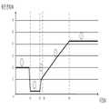
본 발명의 실시예에 따른 단말을 위한 충전 시스템은 전원 어댑터에 의해 출력되는 제3 펄싱 파형의 전압을 제어하고, 전원 어댑터에 의해 출력되는 제3 펄싱 파형의 전압을 직접 단말의 배터리에 로딩함으로써 펄싱하는 출력 전압/전류에 의해 직접 배터리에 대한 급속 충전을 수행할 수 있다. 여기서, 펄싱되는 출력 전압/전류의 크기는 주기적으로 변환되는 것으로, 전통적인 정전압 정전류와 비교할 경우, 리튬 배터리의 리튬 석출 현상을 감소할 수 있고, 배터리의 사용 수명이 향상되며, 충전 인터페이스의 접촉 포인트의 아크 오름 확율 및 강도를 감소할 수 있고, 충전 인터페이스의 수명을 향상시키며, 배터리의 편극 효과 감소, 충전 효율 향상 및 배터리의 발열 감소에 유리하여 단말 충전 시의 안전성 및 신뢰성이 확보된다. 그리고, 전원 어댑터에 의해 출력되는 것은 펄싱 파형의 전압이기에 전원 어댑터 중에서 전해 커패시터를 설치할 필요가 없으며, 전원 어댑터의 간소화, 소형화를 실현할 수 있을 뿐만아니라 원가를 대폭 절감할 수도 있다.The charging system for a terminal according to an embodiment of the present invention controls the voltage of the third pulsing waveform output by the power adapter, and pulsing by directly loading the voltage of the third pulsing waveform outputted by the power adapter into the battery of the terminal. Rapid charging of the battery can be performed directly by the output voltage/current. Here, the magnitude of the pulsed output voltage/current is periodically converted. Compared with the traditional constant voltage constant current, the lithium precipitation phenomenon of the lithium battery can be reduced, the service life of the battery is improved, and the contact point of the charging interface It is possible to reduce the probability and intensity of arc rise, improve the life of the charging interface, reduce polarization effect of the battery, improve charging efficiency, and reduce heat generation of the battery, thereby ensuring safety and reliability when charging the terminal. In addition, since the voltage output by the power adapter is a pulsed waveform voltage, there is no need to install an electrolytic capacitor among the power adapters, simplifying and miniaturization of the power adapter can be realized, and cost can be significantly reduced.
상술한 목적을 달성하기 위하여, 본 발명의 제2 측면의 실시예에 따라 제공되는 전원 어댑터는, 제1 펄싱 파형의 전압이 출력되도록 입력된 교류 전기에 대해 정류를 수행하는 제1 정류 유닛; 제어 신호에 따라 상기 제1 펄싱 파형의 전압에 대해 변조를 수행하는 스위치 유닛; 변조 후의 상기 제1 펄싱 파형의 전압에 따라 제2 펄싱 파형의 전압을 출력하는 변압기; 제3 펄싱 파형의 전압이 출력되도록 상기 제2 펄싱 파형의 전압에 대해 정류를 수행하는 제2 정류 유닛; 상기 제2 정류 유닛과 상호 연결되고, 단말의 제2 충전 인터페이스와 연결 시, 상기 제2 충전 인터페이스를 통해 상기 제3 펄싱 파형의 전압을 상기 단말의 배터리에 로딩하되, 상기 제2 충전 인터페이스와 상기 배터리는 상호 연결되게 구성되는 제1 충전 인터페이스; 전류 샘플링 값이 획득되도록 상기 제2 정류 유닛에 의해 출력되는 전류를 샘플링하는 샘플링 유닛; 및 상기 샘플링 유닛 및 상기 스위치 유닛과 각각 상호 연결되고, 상기 제어 신호를 상기 스위치 유닛에 출력하며, 상기 전류 샘플링 값에 따라 상기 전원 어댑터의 출력 전류가 높은 편임 또는 낮은 편임을 판단할 경우, 상기 제어 신호의 듀티비에 대해 조절을 수행하는 것을 통해 상기 전원 어댑터가 단말에 대해 충전하는 과정이 정전류 충전 절차에 처해 있도록 제어하는 제어 유닛을 포함한다.In order to achieve the above object, a power adapter provided according to an embodiment of the second aspect of the present invention includes: a first rectifying unit that rectifies input AC electricity so that a voltage of a first pulsing waveform is output; A switch unit that modulates the voltage of the first pulsed waveform according to a control signal; A transformer outputting a voltage of a second pulsing waveform according to the voltage of the first pulsing waveform after modulation; A second rectifying unit performing rectification on the voltage of the second pulsing waveform so that the voltage of the third pulsing waveform is output; When the second rectifying unit is interconnected and connected to the second charging interface of the terminal, the voltage of the third pulsing waveform is loaded into the battery of the terminal through the second charging interface, and the second charging interface and the The battery includes a first charging interface configured to be interconnected; A sampling unit that samples the current output by the second rectifying unit so that a current sampling value is obtained; And the sampling unit and the switch unit are interconnected, respectively, and output the control signal to the switch unit, and when determining that the output current of the power adapter is high or low according to the current sampling value, the control And a control unit that controls a process of charging the terminal by the power adapter to be subjected to a constant current charging procedure by adjusting the duty ratio of the signal.
본 발명의 실시예에 따른 전원 어댑터는 제1 충전 인터페이스를 통해 제3 펄싱 파형의 전압을 출력하고, 단말의 제2 충전 인터페이스를 통해 제3 펄싱 파형의 전압을 직접 단말의 배터리에 로딩함으로써 펄싱되는 출력 전압/전류에 의해 직접 배터리에 대한 급속 충전을 실현할 수 있다. 여기서, 펄싱되는 출력 전압/전류의 크기는 주기적으로 변환되는 것으로, 전통적인 정전압 정전류와 비교할 경우, 리튬 배터리의 리튬 석출 현상을 감소할 수 있고, 배터리의 사용 수명이 향상되며, 충전 인터페이스의 접촉 포인트의 아크 오름 확율 및 강도를 감소할 수 있고, 충전 인터페이스의 수명을 향상시키며, 배터리의 편극 효과 감소, 충전 효율 향상 및 배터리의 발열 감소에 유리하여 단말 충전 시의 안전성 및 신뢰성이 확보된다. 그리고, 출력되는 것은 펄싱 파형의 전압이기에 전해 커패시터를 설치할 필요가 없으며, 전원 어댑터의 간소화, 소형화를 실현할 수 있을 뿐만아니라 원가를 대폭 절감할 수도 있다.The power adapter according to an embodiment of the present invention outputs the voltage of the third pulsing waveform through the first charging interface, and pulses by directly loading the voltage of the third pulsing waveform into the battery of the terminal through the second charging interface of the terminal. Rapid charging of the battery can be realized directly by the output voltage/current. Here, the magnitude of the pulsed output voltage/current is periodically converted. Compared with the traditional constant voltage constant current, the lithium precipitation phenomenon of the lithium battery can be reduced, the service life of the battery is improved, and the contact point of the charging interface It is possible to reduce the probability and intensity of arc rise, improve the life of the charging interface, reduce polarization effect of the battery, improve charging efficiency, and reduce heat generation of the battery, thereby ensuring safety and reliability when charging the terminal. Further, since the output is a voltage of a pulsed waveform, there is no need to install an electrolytic capacitor, and not only can the power adapter be simplified and downsized, but also the cost can be significantly reduced.
상술한 목적을 달성하기 위하여, 본 발명의 제3 측면의 실시예에 따라 제공되는 단말을 위한 충전 방법은, 전원 어댑터의 제1 충전 인터페이스와 상기 단말의 제2 충전 인터페이스가 연결되는 경우, 제1 펄싱 파형의 전압이 출력되도록 입력된 교류 전기에 대해 1차 정류를 수행하는 단계; 스위치 유닛에 대한 제어를 통하여 상기 제1 펄싱 파형의 전압에 대해 변조를 수행하고, 변압기에 대한 변환을 통하여 제2 펄싱 파형의 전압이 출력되도록 하는 단계; 제3 펄싱 파형의 전압이 출력되도록 상기 제2 펄싱 파형의 전압에 대해 2차 정류를 수행하며, 상기 제2 충전 인터페이스를 통해 상기 제3 펄싱 파형의 전압을 상기 단말의 배터리에 로딩하는 단계; 전류 샘플링 값이 획득되도록 2차 정류 후의 전류에 대해 샘플링을 수행하는 단계; 및 상기 전류 샘플링 값에 따라 상기 전원 어댑터의 출력 전류가 높은 편임 또는 낮은 편임을 판단할 경우, 상기 스위치 유닛에 출력되는 제어 신호의 듀티비에 대해 조절을 수행하는 것을 통해 상기 전원 어댑터가 단말에 대해 충전하는 과정이 정전류 충전 절차에 처해 있도록 제어하는 단계를 포함한다.In order to achieve the above object, in the charging method for a terminal provided according to an embodiment of the third aspect of the present invention, when the first charging interface of the power adapter and the second charging interface of the terminal are connected, the first Performing primary rectification on the input AC electricity so that the voltage of the pulsed waveform is output; Modulating the voltage of the first pulsing waveform through control of the switch unit, and outputting the voltage of the second pulsing waveform through conversion of the transformer; Performing secondary rectification on the voltage of the second pulsing waveform so that the voltage of the third pulsing waveform is output, and loading the voltage of the third pulsing waveform into the battery of the terminal through the second charging interface; Sampling the current after secondary rectification so that a current sampling value is obtained; And when determining that the output current of the power adapter is high or low according to the current sampling value, the power adapter for the terminal by adjusting the duty ratio of the control signal output to the switch unit. And controlling the charging process to be subjected to a constant current charging procedure.
본 발명의 실시예에 따른 단말을 위한 충전 방법은 전원 어댑터를 제어함으로써 충전 수요를 만족시키는 제3 펄싱 파형의 전압을 출력하고, 전원 어댑터에 의해 출력되는 제3 펄싱 파형의 전압을 직접 단말의 배터리에 로딩함으로써 펄싱하는 출력 전압/전류에 의해 직접 배터리에 대한 급속 충전을 수행할 수 있다. 여기서, 펄싱되는 출력 전압/전류의 크기는 주기적으로 변환되는 것으로, 전통적인 정전압 정전류와 비교할 경우, 리튬 배터리의 리튬 석출 현상을 감소할 수 있고, 배터리의 사용 수명이 향상되며, 충전 인터페이스의 접촉 포인트의 아크 오름 확율 및 강도를 감소할 수 있고, 충전 인터페이스의 수명을 향상시키며, 배터리의 편극 효과 감소, 충전 속도 향상 및 배터리의 발열 감소에 유리하여 단말 충전 시의 안전성 및 신뢰성이 확보된다. 그리고, 전원 어댑터에 의해 출력되는 것은 펄싱 파형의 전압이기에 전원 어댑터 중에서 전해 커패시터를 설치할 필요가 없으며, 전원 어댑터의 간소화, 소형화를 실현할 수 있을 뿐만아니라 원가를 대폭 절감할 수도 있다.In the charging method for a terminal according to an embodiment of the present invention, the voltage of the third pulsing waveform that satisfies the charging demand is output by controlling the power adapter, and the voltage of the third pulsing waveform output by the power adapter is directly transferred to the battery of the terminal. It is possible to perform rapid charging of the battery directly by the pulsed output voltage/current by loading in. Here, the magnitude of the pulsed output voltage/current is periodically converted. Compared with the traditional constant voltage constant current, the lithium precipitation phenomenon of the lithium battery can be reduced, the service life of the battery is improved, and the contact point of the charging interface It is possible to reduce the probability and intensity of arc rise, improve the life of the charging interface, reduce polarization effect of the battery, improve the charging speed, and reduce heat generation of the battery, thereby ensuring safety and reliability when charging the terminal. In addition, since the voltage output by the power adapter is a pulsed waveform voltage, there is no need to install an electrolytic capacitor among the power adapters, simplifying and miniaturization of the power adapter can be realized, and cost can be significantly reduced.
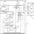
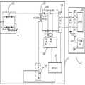
도 1a는 본 발명의 일 실시예에 따른 단말을 위한 충전 시스템이 안티 여기 타입의 스위치 전원을 적용한 블록도이다.
도 1b는 본 발명의 일 실시예에 따른 단말을 위한 충전 시스템이 포워드 여기 타입의 스위치 전원를 적용한 블록도이다.
도 1c는 본 발명의 일 실시예에 따른 단말을 위한 충전 시스템이 푸시풀(push-pull) 타입의 스위치 전원을 적용한 블록도이다.
도 1d는 본 발명의 일 실시예에 따른 단말을 위한 충전 시스템이 하프 브리지 타입의 스위치 전원을 적용한 블록도이다.
도 1e는 본 발명의 일 실시예에 따른 단말을 위한 충전 시스템이 풀 브리지 타입의 스위치 전원을 적용한 블록도이다.
도 2는 본 발명의 일 실시예에 따른 단말을 위한 충전 시스템의 블록도이다.
도 3은 본 발명의 일 실시예에 따른 전원 어댑터가 배터리에 출력하는 충전 전압의 파형 모식도이다.
도 4는 본 발명의 일 실시예에 따른 전원 어댑터가 배터리에 출력하는 충전 전류의 파형 모식도이다.
도 5는 본 발명의 일 실시예에 따라 스위치 유닛에 출력되는 제어 신호의 모식도이다.
도 6은 본 발명의 일 실시예에 따른 급속 충전 과정의 모식도이다.
도 7a는 본 발명의 일 실시예에 따른 단말을 위한 충전 시스템의 블록도이다.
도 7b는 본 발명의 일 실시예에 따른 전원 어댑터에 LC 필터링 회로가 구비된 경우의 블록도이다.
도 8은 본 발명의 다른 일 실시예에 따른 단말을 위한 충전 시스템의 블록도이다.
도 9는 본 발명의 또 다른 일 실시예에 따른 단말을 위한 충전 시스템의 블록도이다.
도 10은 본 발명의 또 다른 일 실시예에 따른 단말을 위한 충전 시스템의 블록도이다.
도 11은 본 발명의 일 실시예에 따른 샘플링 유닛의 블록도이다.
도 12는 본 발명의 또 다른 일 실시예에 따른 단말을 위한 충전 시스템의 블록도이다.
도 13은 본 발명의 일 실시예에 따른 단말의 블록도이다.
도 14는 본 발명의 다른 일 실시예에 따른 단말의 블록도이다.
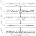
도 15는 본 발명의 실시예에 따른 단말을 위한 충전 방법의 흐름도이다.1A is a block diagram of an anti-excitation type switch power applied to a charging system for a terminal according to an embodiment of the present invention.
1B is a block diagram of a charging system for a terminal according to an embodiment of the present invention to which a forward excitation type switch power is applied.
1C is a block diagram of a charging system for a terminal according to an embodiment of the present invention to which a push-pull type switch power is applied.
1D is a block diagram in which a half-bridge type switch power is applied to a charging system for a terminal according to an embodiment of the present invention.
1E is a block diagram of a charging system for a terminal according to an embodiment of the present invention to which a full bridge type switch power is applied.
2 is a block diagram of a charging system for a terminal according to an embodiment of the present invention.
3 is a schematic diagram of a waveform of a charging voltage output to a battery by a power adapter according to an embodiment of the present invention.
4 is a schematic diagram of a waveform of a charging current output to a battery by a power adapter according to an embodiment of the present invention.
5 is a schematic diagram of a control signal output to a switch unit according to an embodiment of the present invention.
6 is a schematic diagram of a rapid charging process according to an embodiment of the present invention.
7A is a block diagram of a charging system for a terminal according to an embodiment of the present invention.
7B is a block diagram illustrating a case where an LC filtering circuit is provided in a power adapter according to an embodiment of the present invention.
8 is a block diagram of a charging system for a terminal according to another embodiment of the present invention.
9 is a block diagram of a charging system for a terminal according to another embodiment of the present invention.
10 is a block diagram of a charging system for a terminal according to another embodiment of the present invention.
11 is a block diagram of a sampling unit according to an embodiment of the present invention.
12 is a block diagram of a charging system for a terminal according to another embodiment of the present invention.
13 is a block diagram of a terminal according to an embodiment of the present invention.
14 is a block diagram of a terminal according to another embodiment of the present invention.
15 is a flowchart of a charging method for a terminal according to an embodiment of the present invention.
이하, 본 발명의 실시예를 상세히 기재할 것이며, 상기 실시예의 예시는 도면에 도시될 것인데, 그 중 시종일관하게 동일하거나 유사한 부호는 동일하거나 유사한 소자 또는 동일하거나 유사한 기능을 구비한 소자를 지칭한다. 이하, 첨부도면을 참조하여 기재되는 실시예는 예시적인 것으로, 본 발명을 해석하고자 하는 것이지, 본 발명을 제한하는 것으로 해석하면 안된다.Hereinafter, embodiments of the present invention will be described in detail, and examples of the embodiments will be shown in the drawings, among which the same or similar reference numerals consistently refer to the same or similar devices or devices having the same or similar functions. . Hereinafter, the embodiments described with reference to the accompanying drawings are illustrative and intended to interpret the present invention, but should not be construed as limiting the present invention.
이하, 첨부도면을 참조하여 본 발명의 실시예에 따라 제공되는 단말을 위한 충전 시스템 및 전원 어댑터, 단말을 위한 충전 방법을 설명한다.Hereinafter, a charging system and a power adapter for a terminal and a charging method for the terminal provided according to an embodiment of the present invention will be described with reference to the accompanying drawings.
도 1a 내지 도 14를 결부하여 참조하면, 본 발명의 실시예에서 제공하는 단말을 위한 충전 시스템은 전원 어댑터(1) 및 단말(2)을 포함한다.1A to 14, a charging system for a terminal provided in an embodiment of the present invention includes a power adapter 1 and a terminal 2.
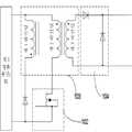
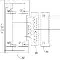
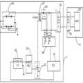
도 2에 도시된 바와 같이, 전원 어댑터(1)는 제1 정류 유닛(101), 스위치 유닛(102), 변압기(103), 제2 정류 유닛(104), 제1 충전 인터페이스(105), 샘플링 유닛(106) 및 제어 유닛(107)을 포함한다. 제1 정류 유닛(101)은 입력되는 교류 전기(상용전기, 예컨대 AC220V)에 대해 정류를 수행하여 제1 펄싱 파형의 전압[예를 들면, 스팀 브레드 웨이브(steamed bread wave)]이 출력되도록 하는데, 여기서, 도 1a에 도시된 바와 같이, 제1 정류 유닛(101)은 4개의 다이오드로 구성된 풀 브리지 정류 회로일 수 있다. 스위치 유닛(102)은 제어 신호에 따라 제1 펄싱 파형의 전압에 대한 변조를 수행하기 위한 것으로, 스위치 유닛(102)은 MOS 튜브로 구성될 수 있으며, MOS 튜브에 대해 펄스 폭 변조(PWM; Pulse Width Modulation) 제어를 수행함으로써 스팀 브레드 웨이브 전압에 대한 초퍼(chopper) 변조를 수행한다. 변압기(103)는 변조 후의 상기 제1 펄싱 파형의 전압에 따라 제2 펄싱 파형의 전압을 출력하고, 제2 정류 유닛(104)은 상기 제2 펄싱 파형의 전압에 대해 정류를 수행함으로써 제3 펄싱 파형의 전압을 출력한다. 여기서, 제2 정류 유닛(104)은 다이오드 또는 MOS 튜브로 구성될 수 있으며, 2차측 동기화 정류가 실현 가능하여 제3 펄싱 파형과 변조 후의 제1 펄싱 파형은 동기화를 유지한다. 설명해야 하는 바는, 제3 펄싱 파형과 변조 후의 제1 펄싱 파형이 동기화를 유지한다는 것은, 구체적으로 제3 펄싱 파형의 위상과 변조 후의 제1 펄싱 파형의 위상이 일치함을 유지하며, 제3 펄싱 파형의 폭 값과 변조 후의 제1 펄싱 파형의 폭 값의 변화 추세가 일치함을 유지한다는 것을 가리킨다. 제1 충전 인터페이스(105)와 제2 정류 유닛(104)은 상호 연결되고, 샘플링 유닛(106)은 제2 정류 유닛(104)에 의해 출력되는 전류를 샘플링함으로써 및/또는 전류 샘플링 값이 획득되도록 하며, 제어 유닛(107)은 샘플링 유닛(106) 및 스위치 유닛(102)과 각각 상호 연결되고, 제어 유닛(107)은 제어 신호를 스위치 유닛(102)에 출력하며, 전류 샘플링 값에 따라 전원 어댑터(1)의 출력 전류가 높은 편임 또는 낮은 편임을 판단할 경우, 제어 신호의 듀티비에 대해 조절을 수행하는 것을 통해 상기 전원 어댑터(1)가 단말(2)에 대해 충전하는 과정이 정전류 충전 절차에 처해 있도록 제어한다.As shown in Fig. 2, the power adapter 1 includes a
여기서, 설명해야 하는 바는, 전원 어댑터(1)의 출력 전류가 높은 편임 또는 낮은 편임은 제2 정류 유닛(104)에 의해 출력되는 제3 펄싱 파형의 피크값 전류 또는 전류 평균치가 정전류 충전 절차의 전류 기준값과 비교하면 높은 편임 또는 낮은 편임을 의미하며, 즉 전류 기준값보다 일정하게 높은 미리 설정된 값이거나 일정하게 낮은 미리 설정된 값이다.Here, it should be explained that the output current of the power adapter 1 is high or low is that the peak value current or current average value of the third pulsing waveform output by the
도 2에 도시된 바와 같이, 단말(2)은 제2 충전 인터페이스(201) 및 배터리(202)를 포함하되, 제2 충전 인터페이스(201)와 배터리(202)는 상호 연결되며, 여기서, 제2 충전 인터페이스(201)와 제1 충전 인터페이스(105)가 연결되는 경우, 제2 충전 인터페이스(201)는 제3 펄싱 파형의 전압을 배터리(202)에 로딩하여 배터리(202)에 대한 충전을 실현한다.As shown in FIG. 2, the terminal 2 includes a
본 발명의 일 실시예에 따라서, 상기 전원 어댑터의 출력 전류가 높은 편임일 경우, 제어 유닛(107)은 상기 제어 신호의 듀티비를 낮춤으로써, 전원 어댑터의 출력 전류를 조절하여 전류 기준값으로 낮추며; 상기 전원 어댑터의 출력 전류가 낮은 편임일 경우, 제어 유닛(107)은 상기 제어 신호의 듀티비를 높임으로써, 전원 어댑터의 출력 전류를 조절하여 전류 기준값으로 높인다.According to an embodiment of the present invention, when the output current of the power adapter is high, the
본 발명의 일 실시예에 따라서, 샘플링 유닛(106)은 전압 샘플링 값이 획득되도록 상기 제2 정류 유닛에 의해 출력되는 전압에 대해 샘플링을 수행하기 위한 것이다. 정전류 충전 절차가 완성된 후, 제어 유닛(107)은 또 상기 전압 샘플링 값에 따라 상기 전원 어댑터의 출력 전압이 높은 편임 또는 낮은 편임을 판단할 경우, 상기 제어 신호의 듀티비에 대해 조절을 수행하는 것을 통해 상기 전원 어댑터가 단말에 대해 충전하는 과정이 정전압 충전 절차에 처해 있도록 제어한다.According to an embodiment of the present invention, the
설명해야 하는 바는, 전원 어댑터(1)의 출력 전압이 높은 편임 또는 낮은 편임은 제2 정류 유닛(104)에 의해 출력되는 제3 펄싱 파형의 피크값 전압 또는 전압 평균치가 정전압 충전 절차의 전압 기준값과 비교하면 높은 편임 또는 낮은 편임을 의미하며, 즉 전압 기준값보다 일정하게 높은 미리 설정된 값이거나 일정하게 낮은 미리 설정된 값이다.It should be explained that the output voltage of the power adapter 1 is high or low is the peak value voltage or voltage average value of the third pulsing waveform output by the
여기서, 상기 전원 어댑터의 출력 전압이 높은 편임일 경우, 제어 유닛(107)은 상기 제어 신호의 듀티비를 낮춤으로써, 전원 어댑터의 출력 전압을 조절하여 전류 기준값으로 낮추며; 상기 전원 어댑터의 출력 전압이 낮은 편임일 경우, 제어 유닛(107)은 상기 제어 신호의 듀티비를 높임으로써, 전원 어댑터의 출력 전압을 조절하여 전압 기준값으로 높인다.Here, when the output voltage of the power adapter is high, the
본 발명의 일 실시예에 있어서, 도 1a에 도시된 바와 같이, 전원 어댑터(1)는 안티 여기 타입의 스위치 전원을 적용할 수 있다. 구체적으로, 변압기(103)는 1차측 권선(winding) 및 2차측 권선을 포함하되, 1차측 권선의 일단은 제1 정류 유닛(101)의 제1 출력단과 상호 연결되고, 제1 정류 유닛(101)의 제2 출력단은 그라운딩(접지)되며, 1차측 권선의 타단과 스위치 유닛(102)은 상호 연결(예를 들어, 상기 스위치 유닛(102)이 MOS 튜브인 경우, 1차측 권선의 타단과 MOS 튜브의 드레인 전극이 상호 연결됨)되고, 변압기(103)는 변조 후의 제1 펄싱 파형의 전압에 따라 제2 펄싱 파형의 전압을 출력한다.In an embodiment of the present invention, as shown in Fig. 1A, the power adapter 1 may apply an anti-excitation type switch power supply. Specifically, the
여기서, 변압기(103)는 고주파 변압기로서, 그 동작 주파수는 50KHz ~ 2MHz일 수 있으며, 고주파 변압기는 변조 후의 제1 펄싱 파형의 전압을 2차측에 커플링시키고, 2차측 권선에 의해 출력된다. 본 발명의 실시예에 있어서, 고주파 변압기를 적용하며, 고주파 변압기의 체적이 저주파 변압기(저주파 변압기는 또한 동작 주파 변압기로도 불리우며, 주로 상용전기의 주파수를 가리키는 바, 예컨대 50Hz 또는 60Hz 의 교류 전기를 가리킴)의 체적보다 작은 특점을 이용하여 전원 어댑터(1)의 소형화를 구현할 수 있다.Here, the
본 발명의 일 실시예에 따르면, 도 1b에 도시된 바와 같이, 상술한 전원 어댑터(1)는 또한 포워드 여기 타입의 스위치 전원을 적용할 수도 있다. 구체적으로, 변압기(103)는 제1 권선, 제2 권선 및 제3 권선을 포함하되, 제1 권선의 동일 명명단은 하나의 역방향 다이오드를 통해 제1 정류 유닛(101)의 제2 출력단과 상호 연결되고, 제1 권선의 상이 명명단은 제2 권선의 동일 명명단과 상호 연결된 후 제1 정류 유닛(101)의 제1 출력단과 상호 연결되며, 제2 권선의 상이 명명단은 스위치 유닛(102)과 상호 연결되고, 제3 권선은 제2 정류 유닛(104)과 상호 연결된다. 여기서, 역방향 다이오드는 안티 피크 절삭 역할을 일으키고, 제1 권선에 의해 생성된 유도 기전력은 역방향 다이오드를 통해 안티 기전력에 대한 폭 한정을 수행할 수 있으며, 폭 한정적 에너지를 제1 정류 유닛에 반환하여 출력할 수 있고, 제1 정류 유닛의 출력에 대해 충전을 수행하며, 제1 권선 중에서 흐르는 전류에 의해 발생된 자기장은 변압기의 철심(Iron core)으로 하여금 자력을 상실하게 하여 변압기 철심 중의 자기장 강도가 초기 상태에로 회복되도록 한다. 변압기(103)는 변조 후의 제1 펄싱 파형의 전압에 따라 제2 펄싱 파형의 전압을 출력한다.According to an embodiment of the present invention, as shown in Fig. 1B, the power adapter 1 described above may also apply a forward excitation type switch power supply. Specifically, the
본 발명의 일 실시예에 따르면, 도 1c에 도시된 바와 같이, 상술한 전원 어댑터(1)는 또한 푸시풀 타입의 스위치 전원을 적용할 수도 있다. 구체적으로, 상기 변압기는 제1 권선, 제2 권선, 제3 권선 및 제4 권선을 포함하되, 상기 제1 권선의 동일 명명단은 상기 스위치 유닛과 상호 연결되고, 상기 제1 권선의 상이 명명단은 상기 제2 권선의 동일 명명단과 상호 연결된 후 상기 제1 정류 유닛의 제1 출력단과 상호 연결되며, 상기 제2 권선의 상이 명명단은 상기 스위치 유닛과 상호 연결되고, 상기 제3 권선의 상이 명명단은 상기 제4 권선의 동일 명명단과 상호 연결되며, 상기 변압기는 변조 후의 상기 제1 펄싱 파형의 전압에 따라 제2 펄싱 파형의 전압을 출력한다.According to an embodiment of the present invention, as shown in FIG. 1C, the above-described power adapter 1 may also apply a push-pull type switch power source. Specifically, the transformer includes a first winding, a second winding, a third winding, and a fourth winding, wherein the same naming end of the first winding is interconnected with the switch unit, and the difference of the first winding is Is interconnected with the same naming end of the second winding and then interconnected with the first output terminal of the first rectifying unit, and the different naming end of the second winding is interconnected with the switch unit, and the difference of the third winding The nomenclature is interconnected with the same nomenclature of the fourth winding, and the transformer outputs a voltage of the second pulsing waveform according to the voltage of the first pulsing waveform after modulation.
도 1c에 도시된 바와 같이, 스위치 유닛(102)은 제1 MOS 튜브(Q1) 및 제2 MOS 튜브(Q2)를 포함하고, 변압기(103)는 제1 권선, 제2 권선, 제3 권선 및 제4 권선을 포함하되, 제1 권선의 동일 명명단은 스위치 유닛(102) 중의 제1 MOS 튜브(Q1)의 드레인 전극과 상호 연결되며, 제1 권선의 상이 명명단은 제2 권선의 동일 명명단과 상호 연결되고, 제1 권선의 상이 명명단과 제2 권선의 동일 명명단 사이의 노드는 제1 정류 유닛(101)의 제1 출력단과 상호 연결되며, 제2 권선의 상이 명명단은 스위치 유닛(102) 중의 제2 MOS 튜브(Q2)의 드레인 전극과 상호 연결되고, 제1 MOS 튜브(Q1)의 소스 전극은 제2 MOS 튜브(Q2)의 소스 전극과 상호 연결된 후 제1 정류 유닛(101)의 제2 출력단과 상호 연결되며, 제3 권선의 동일 명명단은 제2 정류 유닛(104)의 제1 입력단과 상호 연결되고, 제3 권선의 상이 명명단은 제4 권선의 동일 명명단과 상호 연결되며, 제3 권선의 상이 명명단과 제4 권선의 동일 명명단 사이의 노드는 그라운딩되고, 제4 권선의 상이 명명단은 제2 정류 유닛(104)의 제2 입력단과 상호 연결된다.1C, the
도 1c에 도시된 바와 같이, 제2 정류 유닛(104)의 제1 입력단은 제3 권선의 동일 명명단과 상호 연결되고, 제2 정류 유닛(104)의 제2 입력단은 제4 권선의 상이 명명단과 상호 연결되며, 제2 정류 유닛(104)은 상기 제2 펄싱 파형의 전압에 대해 정류를 수행함으로써 제3 펄싱 파형의 전압이 출력되도록 한다. 제2 정류 유닛(104)은 두개의 다이오드를 포함하되, 하나의 다이오드의 양극은 제3 권선의 동일 명명단과 상호 연결되고, 다른 하나의 다이오드의 양극은 제4 권선의 상이 명명단과 상호 연결되며, 두개의 다이오드의 음극은 일체로 연결된다.1C, the first input terminal of the
본 발명의 일 실시예에 따르면, 도 1d에 도시된 바와 같이, 상술한 전원 어댑터(1)는 또한 하프 브리지 타입의 스위치 전원을 적용할 수도 있다. 구체적으로, 스위치 유닛(102)은 제1 MOS 튜브(Q1), 제2 MOS 튜브(Q2) 및 제1 커패시터(C1), 제2 커패시터(C2)를 포함하되, 제1 커패시터(C1)는 제2 커패시터(C2)와 직렬 연결된 후 제1 정류 유닛(101)의 출력단에 병렬 연결되고, 제1 MOS 튜브(Q1)는 제2 MOS 튜브(Q2)와 직렬 연결된 후 제1 정류 유닛(101)의 출력단에 병렬 연결되며, 변압기(103)는 제1 권선, 제2 권선, 제3 권선을 포함하되, 제1 권선의 동일 명명단은 직렬 연결된 제1 커패시터(C1)와 제2 커패시터(C2) 사이의 노드와 상호 연결되고, 제1 권선의 상이 명명단은 직렬 연결된 제1 MOS 튜브(Q1)와 제2 MOS 튜브(Q2) 사이의 노드와 상호 연결되며, 제2 권선의 동일 명명단은 제2 정류 유닛(104)의 제1 입력단과 상호 연결되고, 제2 권선의 상이 명명단은 제3 권선의 동일 명명단과 상호 연결된 후 그라운딩되며, 제3 권선의 상이 명명단은 제2 정류 유닛(104)의 제2 입력단과 상호 연결된다. 변압기(103)는 변조 후의 상기 제1 펄싱 파형의 전압에 따라 제2 펄싱 파형의 전압을 출력한다.According to an embodiment of the present invention, as shown in Fig. 1D, the above-described power adapter 1 may also apply a half-bridge type switch power supply. Specifically, the
본 발명의 일 실시예에 따르면, 도 1e에 도시된 바와 같이, 상술한 전원 어댑터(1)는 또한 풀 브리지 타입의 스위치 전원을 적용할 수도 있다. 구체적으로, 스위치 유닛(102)은 제1 MOS 튜브(Q1), 제2 MOS 튜브(Q2) 및 제3 MOS 튜브(Q3), 제4 MOS 튜브(Q4)를 포함하되, 제3 MOS 튜브(Q3)는 제4 MOS 튜브(Q4)와 직렬 연결된 후 제1 정류 유닛(101)의 출력단에 병렬 연결되고, 제1 MOS 튜브(Q1)는 제2 MOS 튜브(Q2)와 직렬 연결된 후 제1 정류 유닛(101)의 출력단에 병렬 연결되며, 변압기(103)는 제1 권선, 제2 권선 및 제3 권선을 포함하되, 제1 권선의 동일 명명단은 직렬 연결된 제3 MOS 튜브(Q3)와 제4 MOS 튜브(Q4) 사이의 노드와 상호 연결되고, 제1 권선의 상이 명명단은 직렬 연결된 제1 MOS 튜브(Q1)와 제2 MOS 튜브(Q2) 사이의 노드와 상호 연결되며, 제2 권선의 동일 명명단은 제2 정류 유닛(104)의 제1 입력단과 상호 연결되고, 제2 권선의 상이 명명단은 제3 권선의 동일 명명단과 상호 연결된 후 그라운딩되며, 제3 권선의 상이 명명단은 제2 정류 유닛(104)의 제2 입력단과 상호 연결된다. 변압기(103)는 변조 후의 상기 제1 펄싱 파형의 전압에 따라 제2 펄싱 파형의 전압을 출력한다.According to an embodiment of the present invention, as shown in Fig. 1E, the above-described power adapter 1 may also apply a full bridge type switch power supply. Specifically, the
따라서, 본 발명의 실시예에 있어서, 상술한 전원 어댑터(1)는 안티 여기 타입의 스위치 전원, 포워드 여기 타입의 스위치 전원, 푸시풀 타입의 스위치 전원, 하프 브리지 타입의 스위치 전원 및 풀 브리지 타입의 스위치 전원 중의 임의의 한가지 스위치 전원을 적용하여 펄싱 파형의 전압을 출력할 수 있다.Accordingly, in the embodiment of the present invention, the power adapter 1 described above is an anti-excitation type switch power supply, a forward excitation type switch power supply, a push-pull type switch power supply, a half-bridge type switch power supply, and a full-bridge type switch power supply. The voltage of the pulsed waveform can be output by applying any one of the switch power supplies.
나아가, 도 1a에 도시된 바와 같이, 제2 정류 유닛(104)은 변압기(103)의 2차측 권선과 상호 연결되고, 제2 정류 유닛(104)은 제2 펄싱 파형의 전압에 대해 정류를 수행함으로써 제3 펄싱 파형의 전압이 출력되도록 한다. 여기서, 제2 정류 유닛(104)은 다이오드로 구성될 수 있으며, 2차측 동기화 정류를 실현하여 제3 펄싱 파형과 변조 후의 제1 펄싱 파형이 동기화를 유지하게 되는데, 설명해야 하는 바는, 제3 펄싱 파형과 변조 후의 제1 펄싱 파형이 동기화를 유지한다는 것은, 구체적으로 제3 펄싱 파형의 위상과 변조 후의 제1 펄싱 파형의 위상이 일치함을 유지하며, 제3 펄싱 파형의 폭 값과 변조 후의 제1 펄싱 파형의 폭 값의 변화 추세가 일치함을 유지한다는 것을 가리킨다. 제1 충전 인터페이스(105)는 제2 정류 유닛(104)과 상호 연결되고, 샘플링 유닛(106)은 제2 정류 유닛(104)에 의해 출력된 전압 및/또는 전류를 샘플링함으로써 전압 샘플링 값 및/또는 전류 샘플링 값이 획득되도록 하며, 제어 유닛(107)은 샘플링 유닛(106) 및 스위치 유닛(102)과 상호 연결되고, 제어 유닛(107)은 제어 신호를 스위치 유닛(102)에 출력하며, 전압 샘플링 값 및/또는 전류 샘플링 값에 따라 제어 신호의 듀티비를 조절함으로써 상기 제2 정류 유닛(104)에 의해 출력되는 제3 펄싱 파형의 전압으로 하여금 충전 수요를 만족시키도록 한다.Further, as shown in FIG. 1A, the
도 1a에 도시된 바와 같이, 단말(2)은 제2 충전 인터페이스(201) 및 배터리(202)를 포함하고, 제2 충전 인터페이스(201)는 배터리(202)와 상호 연결되는데, 여기서, 제2 충전 인터페이스(201)와 제1 충전 인터페이스(105)가 연결되는 경우, 제2 충전 인터페이스(201)는 제3 펄싱 파형의 전압을 배터리(202)에 로딩하여 배터리(202)에 대한 충전을 실현한다.As shown in FIG. 1A, the terminal 2 includes a
여기서, 설명해야 하는 바는, 제3 펄싱 파형의 전압이 충전 수요를 만족시킨다는 것은, 제3 펄싱 파형의 전압 및 전류는 배터리 충전 시의 충전 전압 및 충전 전류를 만족해야 한다는 것을 가리킨다. 다시 말해서, 제어 유닛(107)은 샘플링해낸 전원 어댑터에 의해 출력되는 전압 및/또는 전류에 따라 제어 신호(예컨대 PWM 신호)의 듀티비를 조절하여 제2 정류 유닛(104)의 출력을 실시간적으로 조정하고, 폐환 조절 제어를 실현함으로써 제3 펄싱 파형의 전압이 단말(2)의 충전 수요를 만족하도록 하며, 배터리(202)가 안전하고도 신뢰성 있게 충전되도록 확보하는 바, 구체적으로 PWM 신호의 듀티비를 통해 배터리(202)에 출력되는 충전 전압을 조절하는 파형은 도 3에 도시된 바와 같고, PWM 신호의 듀티비를 통해 배터리(202)에 출력되는 충전 전류를 조절하는 파형은 도 4에 도시된 바와 같다.Here, it should be described that the voltage of the third pulsing waveform satisfies the charging demand indicates that the voltage and current of the third pulsing waveform must satisfy the charging voltage and charging current during battery charging. In other words, the
이해 가능할 것인 바, PWM 신호의 듀티비 조절 시, 전압 샘플링 값에 따라 조절 명령을 생성할 수도 있지만, 전류 샘플링 값에 따라 생성하거나 전압 샘플링 값 및 전류 샘플링 값에 따라 생성할 수도 있다.As will be understood, when adjusting the duty ratio of the PWM signal, an adjustment command may be generated according to a voltage sampling value, but may be generated according to a current sampling value or a voltage sampling value and a current sampling value.
따라서, 본 발명의 실시예에 있어서, 스위치 유닛(102)에 대한 제어를 통해 정류 후의 제1 펄싱 파형의 전압 즉 스팀 브레드 웨이브 전압에 대해 직접 PWM 초퍼 변조를 수행하고, 고주파 변압기에 송달하며, 고주파 변압기를 통하여 1차측으로부터 2차측에 커플링된 다음, 동기화 정류를 거친 후 스팀 브레드 웨이브 전압/전류로 환원되고, 배터리에 직접 수송되어 배터리에 대한 급속 충전을 실현한다. 여기서, 스팀 브레드 웨이브의 전압 폭 값은 PWM 신호의 듀티비를 통해 조절될 수 있으며, 전원 어댑터의 출력이 배터리의 충전 수요를 만족시키도록 구현한다. 이로부터 알다시피, 본 발명의 실시예의 전원 어댑터는 1차측, 2차측의 전기분해 커패시터를 제거하고, 스팀 브레드 웨이브 전압에 의해 직접 배터리를 충전함으로써 전원 어댑터의 체적을 감소시켜 전원 어댑터의 소형화를 실현하며, 원가를 대폭적으로 저감할 수 있다.Therefore, in an embodiment of the present invention, PWM chopper modulation is directly performed on the voltage of the first pulsing waveform, that is, the steam bread wave voltage, after rectification through control of the
여기서, 본 발명의 일 구체적인 예시 중에서, 제어 유닛(107)은 마이크로 제어 프로세서(MCU; Micro Controller Unit)일 수 있다. 즉, 스위치 구동 제어 기능, 동기화 정류 기능, 전압 전류 조절 제어 기능이 집적된 마이크로 프로세서일 수 있다.Here, among a specific example of the present invention, the
본 발명의 일 실시예에 따르면, 제어 유닛(107)은 또한 전압 샘플링 값 및/또는 전류 샘플링 값에 따라 제어 신호의 주파수를 조절한다. 즉, 스위치 유닛(102)에 제어 가능하게 출력되는 PWM 신호는 소정 시간동안 지속적으로 출력된 후 다시 출력이 정지되고, 소정 시간 정지된 후 다시 PWM 신호의 출력을 작동하는데, 이는 배터리에 로딩된 전압이 비연속적으로 이어지게 하여 배터리의 간헐성 충전이 실현되기에, 배터리 연속 충전 시 발열이 엄중하여 초래되는 보안성 우려를 해소할 수 있으며, 배터리 충전의 신뢰성 및 안전성을 향상시킨다.According to an embodiment of the present invention, the
리튬 배터리의 경우, 저온 조건하에서, 리튬 배터리 자체의 이온 및 전자 도전성 능령의 저하로 인해, 충전 과정 중 편극화 정도의 가중화를 쉽게 야기할 수 있는데, 지속적 충전 방식은 이와 같은 편극화 현상으로 하여금 가일층 선명해지게 하는 동시에, 리튬 석출의 발생 가능성을 증가시켜 배터리의 보안 성능에 영향을 미친다. 또한, 지속적인 충전은 충전에 의해 열량이 끊임 없이 축적되는 현상을 초래하게 되어 배터리 내부 온도가 끊임 없이 상승하게 하고, 온도가 소정 한계 값을 초과하는 경우, 배터리 성능의 발휘가 제한적일 수 있으며, 아울러 보안 우려가 증가된다.In the case of a lithium battery, under low temperature conditions, it can easily cause a weighting of the degree of polarization during the charging process due to a decrease in the ability of ionic and electronic conductivity of the lithium battery itself.The continuous charging method causes such polarization phenomenon. At the same time, it makes the battery more clear and increases the likelihood of lithium precipitation, thereby affecting the security performance of the battery. In addition, continuous charging causes a phenomenon in which the amount of heat is constantly accumulated by charging, causing the internal temperature of the battery to constantly rise. If the temperature exceeds a predetermined limit, the performance of the battery may be limited, and security Concerns increase.
반면에 본 발명의 실시예에서는, 제어 신호의 주파수에 대한 조절을 통해 전원 어댑터가 간헐적으로 출력되게 한다. 즉, 배터리 충전 과정 중 배터리 정지 거치 과정을 도입하는 것에 해당되어 지속적인 충전 과정 중 편극으로 인해 리튬 석출 현상이 야기되는 것을 완화할 수 있으며, 생성 열이 지속적으로 누적되는 영향을 감쇄하고, 온도 저감 효과가 달성되며, 배터리 충전의 신뢰성 및 안전성을 확보한다.On the other hand, in the embodiment of the present invention, the power adapter is intermittently output through adjustment of the frequency of the control signal. In other words, it corresponds to the introduction of the battery stop step during the battery charging process, so that the occurrence of lithium precipitation due to polarization during the continuous charging process can be alleviated, the effect of continuously accumulating generated heat is reduced, and the effect of reducing the temperature. Is achieved, and ensures the reliability and safety of battery charging.
여기서, 스위치 유닛(102)에 출력되는 제어 신호는 도 5에 도시된 것과 같은 바, 먼저 소정 시간동안 지속적으로 PWM 신호를 출력한 다음, 소정 시간동안 출력을 정지하며, 그리고 다시 소정 시간동안 PWM 신호를 출력하고, 스위치 유닛(102)에 출력되는 제어 신호의 간헐성을 구현하며, 주파수는 조절 가능하게 마련한다.Here, the control signal output to the
도 1a에 도시된 바와 같이, 제어 유닛(107)는 제1 충전 인터페이스(105)와 상호 연결되고, 제어 유닛(107)은 또한 제1 충전 인터페이스(105)를 통해 단말(2)과 통신을 수행하여 단말(2)의 상태 정보가 획득되도록 한다. 이와 같이, 제어 유닛(107)은 또한 단말의 상태 정보, 전압 샘플링 값 및/또는 전류 샘플링 값에 따라 제어 신호(예를 들어 PWM 신호)의 듀티비를 조절한다.1A, the
여기서, 단말의 상태 정보는 상기 배터리의 전기량, 상기 배터리의 온도, 상기 배터리의 전압, 상기 단말의 인터페이스 정보, 및 상기 단말의 통로 저항의 정보 등을 포함할 수 있다.Here, the state information of the terminal may include electricity amount of the battery, temperature of the battery, voltage of the battery, interface information of the terminal, and information of path resistance of the terminal.
구체적으로, 제1 충전 인터페이스(105)는 전원선 및 데이터선을 포함하되, 전원선은 배터리를 위한 충전을 수행하고, 데이터선은 단말과의 통신을 수행한다. 제2 충전 인터페이스(201)와 제1 충전 인터페이스(105)가 연결되는 경우, 전원 어댑터(1)와 단말(2) 사이는 서로 통신 문의 명령을 송신할 수 있으며, 상응한 응답 명령을 수신한 후, 전원 어댑터(1)와 단말(2) 사이에 통신 연결을 구축하며, 제어 유닛(107)은 단말(2)의 상태 정보를 획득할 수 있어 단말(2)과 충전 모드 및 충전 파라미터(예를 들면, 충전 전류 및 충전 전압)에 대한 협의를 수행하고, 충전 과정에 대해 제어를 수행한다.Specifically, the
여기서, 전원 어댑터 및/또는 단말에 의해 지원되는 충전 모드는 일반 충전 모드 및 급속 충전 모드를 포함할 수 있다. 급속 충전 모드의 충전 속도는 일반 충전 모드의 충전 속도보다 크다(예를 들어, 급속 충전 모드의 충전 전류는 일반 충전 모드의 충전 전류보다 크다). 일반적으로, 일반 충전 모드는 정격 출력 전압이 5V이며, 정격 출력 전류는 2.5A보다 작거나 같은 충전 모드인 것으로 이해할 수 있다. 이밖에, 일반 충전 모드 하에서, 전원 어댑터 출력 포트 데이터선 중의 D+와 D-는 단락될 수 있다. 반면에 본 발명의 실시예 중의 급속 충전 모드는 상이한 바, 본 발명의 실시예의 급속 충전 모드 하에서 전원 어댑터는 데이터선 중의 D+ 및 D-를 이용하여 단말과 통신을 수행함으로써 데이터 교환을 실현할 수 있다. 즉, 전원 어댑터와 단말 사이에 서로 급속 충전 명령을 수신할 수 있다. 전원 어댑터는 단말을 향해 급속 충전 문의 명령을 송신하고, 단말의 급속 충전 응답 명령을 수신한 후, 단말의 응답 명령에 따라 전원 어댑터는 단말의 상태 정보를 획득하며, 급속 충전 모드를 작동시키고, 급속 충전 모드 하의 충전 전류는 2.5A보다 클 수 있으며, 예컨대 4.5A에 도달하거나 더욱 클 수도 있다. 그러나, 본 발명의 실시예는 일반 충전 모드에 대해 구체적으로 한정하지 않는 바, 전원 어댑터가 두가지 충전 모드를 지원하기만 하면 되며, 그 중 한가지 충전 모드의 충전 속도(또는 전류)가 다른 한가지 충전 모드의 충전 속도보다 크면, 충전 속도가 비교적 느린 충전 모드를 일반 충전 모드로 이해할 수 있다. 충전 전력에 대해 말하면, 급속 충전 모드 하의 충전 전력은 15 W보다 크거나 같을 수 있다.Here, the charging mode supported by the power adapter and/or the terminal may include a normal charging mode and a fast charging mode. The charging speed of the fast charging mode is greater than that of the normal charging mode (for example, the charging current in the fast charging mode is greater than that of the normal charging mode). In general, it can be understood that the normal charging mode is a charging mode with a rated output voltage of 5V and a rated output current of less than or equal to 2.5A. In addition, under normal charging mode, D+ and D- in the power adapter output port data line may be shorted. On the other hand, the fast charging mode in the embodiment of the present invention is different, and in the fast charging mode of the embodiment of the present invention, the power adapter can perform data exchange by performing communication with the terminal using D+ and D- in the data line. That is, it is possible to receive a quick charge command between the power adapter and the terminal. The power adapter transmits a quick charge inquiry command to the terminal, receives the quick charge response command from the terminal, and according to the response command from the terminal, the power adapter acquires the status information of the terminal, activates the quick charge mode, and The charging current under charging mode may be greater than 2.5A, for example it may reach 4.5A or even greater. However, the embodiment of the present invention is not specifically limited to the general charging mode, and the power adapter only needs to support two charging modes, and one charging mode in which the charging speed (or current) of one charging mode is different. If it is greater than the charging rate of, the charging mode, which is relatively slow in charging rate, can be understood as a normal charging mode. Speaking of charging power, the charging power under the fast charging mode may be greater than or equal to 15 W.
즉, 제어 유닛(107)은 제1 충전 인터페이스(105)를 통해 단말(2)과 통신을 수행함으로써 충전 모드가 결정되도록 하는데, 여기서, 충전 모드는 급속 충전 모드 및 일반 충전 모드를 포함한다.That is, the
구체적으로, 상기 전원 어댑터와 단말은 통용 직렬 버스(Universal Serial Bus; USB)를 통해 인터페이스와 상호 연결되며, 상기 USB 인터페이스는 일반 USB 인터페이스일 수도 있고, 마이크로(micro) USB 인터페이스일 수도 있다. USB 인터페이스 중의 데이터선 즉 제1 충전 인터페이스 중의 데이터선은 상기 전원 어댑터 및 상기 단말의 양방향 통신을 위해 이용되고, 상기 데이터선은 USB 인터페이스 중의 D+ 라인 및/또는 D- 라인일 수 있으며, 소위의 양방향 통신은 전원 어댑터 및 단말 양방이 정보 상호 작용을 수행하는 것을 의미할 수 있다.Specifically, the power adapter and the terminal are interconnected with an interface through a universal serial bus (USB), and the USB interface may be a general USB interface or a micro USB interface. The data line in the USB interface, that is, the data line in the first charging interface, is used for bidirectional communication between the power adapter and the terminal, and the data line may be a D+ line and/or a D- line in the USB interface. Communication may mean that both the power adapter and the terminal perform information interaction.
여기서, 상기 전원 어댑터는 상기 USB 인터페이스 중의 데이터선을 통해 상기 단말과 양방향 통신을 수행함으로써 상기 급속 충전 모드를 사용하여 상기 단말을 위한 충전을 수행할 것을 결정한다.Here, the power adapter determines to perform charging for the terminal using the fast charging mode by performing bidirectional communication with the terminal through a data line in the USB interface.
설명해야 하는 바는, 전원 어댑터와 단말이 급속 충전 모드를 적용하여 상기 단말을 위한 충전을 수행할 것인지 여부를 협의하는 과정 중, 전원 어댑터는 단말과 단지 연결 상태를 유지할 뿐, 충전은 수행하지 않을 수 있으며, 일반 충전 모드를 적용하여 단말을 위한 충전을 수행할 수도 있고, 작은 전류를 적용하여 단말을 위한 충전을 수행할 수도 있는 바, 본 발명의 실시예는 이에 대해 구체적으로 한정하지 않는다.What should be explained is that in the process of discussing whether to perform charging for the terminal by applying the fast charging mode between the power adapter and the terminal, the power adapter only maintains a connected state with the terminal, but does not perform charging. In addition, charging for the terminal may be performed by applying a general charging mode, or charging for the terminal may be performed by applying a small current, and embodiments of the present invention are not specifically limited thereto.
상기 전원 어댑터는 충전 전류를 상기 급속 충전 모드에 대응되는 충전 전류에 도달하도록 조정하고, 상기 단말을 위한 충전을 수행한다. 전원 어댑터는 급속 충전 모드를 적용하여 단말을 위한 충전을 수행할 것을 결정한 후, 직접 충전 전류를 급속 충전 모드에 대응되는 충전 전류에 도달하도록 조정할 수도 있고, 단말과 급속 충전 모드의 충전 전류를 협의할 수도 있다. 예를 들어, 단말 중의 배터리의 현재 전기량에 따라 급속 충전 모드에 대응되는 충전 전류를 결정할 수 있다.The power adapter adjusts the charging current to reach a charging current corresponding to the fast charging mode, and performs charging for the terminal. The power adapter may adjust the direct charging current to reach the charging current corresponding to the fast charging mode after determining to perform charging for the terminal by applying the fast charging mode, or negotiate the charging current of the fast charging mode with the terminal. May be. For example, the charging current corresponding to the fast charging mode may be determined according to the current amount of electricity of the battery in the terminal.
본 발명의 실시예에 있어서, 전원 어댑터는 맹목적으로 출력 전류를 증가하여 급속 충전을 수행하는 것이 아니라, 단말과 양방향 통신을 수행함으로써 급속 충전 모드의 적용 가능 여부를 협의하는 바, 종래기술과 비교할 경우, 급속 충전 과정의 보안성을 향상시킨다.In an embodiment of the present invention, the power adapter does not perform fast charging by blindly increasing the output current, but discusses whether the fast charging mode can be applied by performing bidirectional communication with the terminal. , Improve the security of the fast charging process.
선택 가능하게, 일 실시예로서, 제어 유닛(107)은 상기 제1 충전 인터페이스 중의 데이터선을 통해 상기 단말과 양방향 통신을 수행함으로써 상기 급속 충전 모드를 사용하여 상기 단말을 위한 충전을 수행할 것을 결정하는 경우, 상기 제어 유닛은 상기 단말을 향해 제1 명령을 송신하되, 상기 제1 명령은 상기 단말이 상기 급속 충전 모드를 작동시키는지 여부를 문의하고; 상기 제어 유닛은 상기 단말로부터 상기 제1 명령의 답변 명령을 수신하며, 상기 제1 명령의 답변 명령은 상기 단말로 하여금 상기 급속 충전 모드를 작동하는데 동의하도록 지시한다.Optionally, as an embodiment, the
선택 가능하게, 일 실시예로서, 상기 제어 유닛이 상기 단말을 향해 상기 제1 명령을 송신하기 저에, 상기 전원 어댑터와 상기 단말 사이에서 상기 일반 충전 모드를 통해 충전이 진행되고, 상기 제어 유닛이 상기 일반 충전 모드의 충전 시간 길이가 미리 설정 문턱값보다 크다는 것을 결정한 후, 상기 단말을 향해 상기 제1 명령을 송신한다.Selectably, as an embodiment, when the control unit transmits the first command to the terminal, charging is performed between the power adapter and the terminal through the normal charging mode, and the control unit After determining that the length of the charging time in the normal charging mode is greater than a preset threshold, the first command is transmitted to the terminal.
이해해야 할 바로는, 전원 어댑터에 의해 상기 일반 충전 모드의 충전 시간 길이가 미리 설정 문턱값보다 크다는 것이 결정된 후, 전원 어댑터는 단말이 이미 자신은 전원 어댑터라는 것을 인지하였다고 인정할 수 있으며, 급속 문의 통신을 작동시킬 수 있다.It should be understood that, after it is determined by the power adapter that the length of the charging time in the general charging mode is greater than the preset threshold, the power adapter can admit that the terminal has already recognized that it is a power adapter, and can communicate with a quick inquiry. You can make it work.
선택 가능하게, 일 실시예로서, 상기 전원 어댑터는 미리 설정된 전류 문턱값보다 크거나 같은 충전 전류를 적용하여 미리 설정 시간 길이동안 충전을 진행한 후, 상기 단말을 향해 상기 제1 명령을 송신한다.Selectably, as an embodiment, the power adapter applies a charging current equal to or greater than a preset current threshold to perform charging for a preset time length, and then transmits the first command to the terminal.
선택 가능하게, 일 실시예로서, 상기 제어 유닛은 또한 상기 스위치 유닛을 제어함으로써 상기 전원 어댑터를 제어하여 충전 전류를 상기 급속 충전 모드에 대응되는 충전 전류에 도달하도록 조정하고, 상기 전원 어댑터가 상기 급속 충전 모드에 대응되는 충전 전류로 상기 단말을 위한 충전을 수행하기 전에, 상기 제어 유닛은 상기 제1 충전 인터페이스 중의 데이터선을 통해 상기 단말과 양방향 통신을 수행함으로써 상기 급속 충전 모드에 대응되는 충전 전압이 결정되도록 하고, 상기 전원 어댑터를 제어하여 충전 전압을 상기 급속 충전 모드에 대응되는 충전 전압에 도달하도록 조정한다.Selectably, as an embodiment, the control unit also controls the power adapter by controlling the switch unit to adjust the charging current to reach a charging current corresponding to the rapid charging mode, and the power adapter Before performing charging for the terminal with a charging current corresponding to the charging mode, the control unit performs bidirectional communication with the terminal through a data line in the first charging interface, so that the charging voltage corresponding to the fast charging mode is And controlling the power adapter to adjust a charging voltage to reach a charging voltage corresponding to the fast charging mode.
선택 가능하게, 일 실시예로서, 상기 제어 유닛은 상기 제1 충전 인터페이스 중의 데이터선을 통해 상기 단말과 양방향 통신을 수행함으로써 상기 급속 충전 모드에 대응되는 충전 전압 결정 시, 상기 제어 유닛은 상기 단말을 향해 제2 명령을 송신하되, 상기 제2 명령은 상기 전원 어댑터의 현재 출력 전압을 상기 급속 충전 모드의 충전 전압으로 취급되기 적합한지 여부를 문의하고; 상기 제어 유닛은 상기 단말에 의해 송신된 상기 제2 명령의 답변 명령을 수신하되, 상기 제2 명령의 답변 명령은 상기 전원 어댑터의 현재 출력 전압의 적절함, 높은 편임 또는 낮은 편임을 지시하며; 상기 제어 유닛은 상기 제2 명령의 답변 명령에 따라 급속 충전 모드의 충전 전압을 결정한다.Selectably, as an embodiment, when determining a charging voltage corresponding to the fast charging mode by performing bidirectional communication with the terminal through the data line of the first charging interface, the control unit Send a second command to the second command, wherein the second command inquires whether the current output voltage of the power adapter is suitable to be treated as a charging voltage in the fast charging mode; The control unit receives a response command to the second command transmitted by the terminal, wherein the response command to the second command indicates that the current output voltage of the power adapter is appropriate, high or low; The control unit determines a charging voltage in the fast charging mode according to the response command of the second command.
선택 가능하게, 일 실시예로서, 상기 제어 유닛은 상기 전원 어댑터를 제어하여 충전 전류를 상기 급속 충전 모드에 대응되는 충전 전류에 도달하도록 조정하기 전에, 상기 제1 충전 인터페이스 중의 데이터선을 통해 상기 단말과 양방향 통신을 수행함으로써 상기 급속 충전 모드에 대응되는 충전 전류가 결정되도록 한다.Selectably, as an embodiment, the control unit controls the power adapter to adjust the charging current to reach a charging current corresponding to the fast charging mode, before controlling the terminal through a data line of the first charging interface. The charging current corresponding to the fast charging mode is determined by performing two-way communication with the device.
선택 가능하게, 일 실시예로서, 상기 제어 유닛은 상기 제1 충전 인터페이스 중의 데이터선을 통해 상기 단말과 양방향 통신을 수행함으로써 상기 급속 충전 모드에 대응되는 충전 전류 결정 시, 상기 제어 유닛은 상기 단말을 향해 제3 명령을 송신하되, 상기 제3 명령은 상기 단말이 현재 지원하는 최대 충전 전류를 문의하고; 상기 제어 유닛은 상기 단말에 의해 송신된 상기 제3 명령의 답변 명령을 수신하되, 상기 제3 명령의 답변 명령은 상기 단말이 현재 지원하는 최대 충전 전류를 지시하며; 상기 제어 유닛은 상기 제3 명령의 답변 명령에 따라 상기 급속 충전 모드의 충전 전류를 결정한다.Selectably, as an embodiment, when determining a charging current corresponding to the fast charging mode by performing bidirectional communication with the terminal through the data line of the first charging interface, the control unit Transmits a third command toward, wherein the third command inquires about a maximum charging current currently supported by the terminal; The control unit receives a response command to the third command transmitted by the terminal, wherein the response command to the third command indicates a maximum charging current currently supported by the terminal; The control unit determines the charging current in the fast charging mode according to the response command of the third command.
전원 어댑터는 상술한 최대 충전 전류를 직접 급속 충전 모드의 충전 전류로 결정하거나, 충전 전류를 상기 최대 충전 전류보다 작은 어느 한 전류값으로 설치할 수 있다.The power adapter may directly determine the above-described maximum charging current as the charging current in the rapid charging mode, or install the charging current as any one current value smaller than the maximum charging current.
선택 가능하게, 일 실시예로서, 상기 전원 어댑터가 상기 급속 충전 모드를 적용하여 상기 단말을 위한 충전을 수행하는 과정 중, 상기 제어 유닛은 또한 상기 제1 충전 인터페이스 중의 데이터선을 통해 상기 단말과 양방향 통신을 수행함으로써 상기 스위치 유닛에 대한 제어를 통해 상기 전원 어댑터가 배터리에 출력하는 충전 전류를 끊임 없이 조정한다.Selectably, as an embodiment, in the process of the power adapter performing charging for the terminal by applying the fast charging mode, the control unit is also bidirectionally connected to the terminal through a data line in the first charging interface. By performing communication, the charging current output to the battery by the power adapter is constantly adjusted through control of the switch unit.
전원 어댑터는 단말의 현재 상태 정보를 끊임 없이 문의할 수 있는 바, 예컨대 단말의 배터리 전압, 배터리 전기량 등을 문의하여 전원 어댑터가 배터리에 출력하는 충전 전류를 끊임 없이 조정한다.The power adapter can continuously inquire about the current state information of the terminal. For example, the power adapter continuously adjusts the charging current output to the battery by inquiring about the battery voltage of the terminal and the amount of electricity in the battery.
선택 가능하게, 일 실시예로서, 상기 제어 유닛은 상기 제1 충전 인터페이스 중의 데이터선을 통해 상기 단말과 양방향 통신을 수행함으로써 상기 스위치 유닛에 대한 제어를 통해 상기 전원 어댑터가 배터리에 출력하는 충전 전류를 끊임 없이 조정 시, 상기 제어 유닛은 상기 단말을 향해 제4 명령을 송신하되, 상기 제4 명령은 상기 단말 내의 배터리의 현재 전압을 문의하고; 상기 제어 유닛은 상기 단말에 의해 송신된 상기 제4 명령의 답변 명령을 수신하되, 상기 제4 명령의 답변 명령은 상기 단말 내의 배터리의 현재 전압을 지시하며; 상기 제어 유닛은 상기 배터리의 현재 전압에 따라 상기 스위치 유닛에 대한 제어를 통해 상기 전원 어댑터가 배터리에 출력하는 충전 전류가 조정되도록 한다.Selectably, as an embodiment, the control unit performs two-way communication with the terminal through a data line in the first charging interface, so that the charging current output from the power adapter to the battery through control of the switch unit Upon constant adjustment, the control unit transmits a fourth command to the terminal, the fourth command inquiring the current voltage of the battery in the terminal; The control unit receives a response command to the fourth command transmitted by the terminal, wherein the response command to the fourth command indicates a current voltage of the battery in the terminal; The control unit adjusts the charging current output to the battery by the power adapter through control of the switch unit according to the current voltage of the battery.
선택 가능하게, 일 실시예로서, 상기 제어 유닛은 상기 배터리의 현재 전압, 미리 설정된 배터리 전압값 및 충전 전류값의 대응 관계에 따라 상기 스위치 유닛에 대한 제어를 통해 상기 전원 어댑터가 배터리에 출력하는 충전 전류를 상기 배터리의 현재 전압에 대응되는 충전 전류값에 도달하도록 조정한다.Selectably, as an embodiment, the control unit is a charging output from the power adapter to the battery through control of the switch unit according to a correspondence relationship between the current voltage of the battery, a preset battery voltage value, and a charging current value. The current is adjusted to reach a charging current value corresponding to the current voltage of the battery.
구체적으로, 전원 어댑터는 배터리 전압값과 충전 전류값의 대응 관계를 미리에 저장할 수 있으며, 전원 어댑터는 상기 제1 충전 인터페이스 중의 데이터선을 통해 상기 단말과 양방향 통신을 수행함으로써 단말측으로부터 단말 내에 저장된 배터리 전압값과 충전 전류값의 대응 관계를 획득한다.Specifically, the power adapter may store a correspondence relationship between the battery voltage value and the charging current value in advance, and the power adapter performs bidirectional communication with the terminal through a data line in the first charging interface, thereby storing the stored in the terminal from the terminal side. A correspondence relationship between the battery voltage value and the charging current value is obtained.
선택 가능하게, 일 실시예로서, 상기 전원 어댑터가 상기 급속 충전 모드를 사용하여 상기 단말을 위한 충전을 수행하는 과정 중, 상기 제어 유닛은 또한 상기 제1 충전 인터페이스 중의 데이터선을 통해 상기 단말과 양방향 통신을 수행함으로써 상기 제1 충전 인터페이스와 상기 제2 충전 인터페이스 사이에 접촉 불량이 존재하는지 여부를 결정한다. 여기서, 상기 제1 충전 인터페이스와 상기 제2 충전 인터페이스 사이에 접촉 불량이 존재한다는 것이 결정된 경우, 상기 제어 유닛은 상기 전원 어댑터를 제어하여 상기 급속 충전 모드로부터 탈출한다.Selectably, as an embodiment, in the process of the power adapter performing charging for the terminal using the fast charging mode, the control unit also bidirectionally with the terminal through the data line in the first charging interface. By performing communication, it is determined whether there is a contact failure between the first charging interface and the second charging interface. Here, when it is determined that there is a contact failure between the first charging interface and the second charging interface, the control unit controls the power adapter to escape from the fast charging mode.
선택 가능하게, 일 실시예로서, 상기 제1 충전 인터페이스와 상기 제2 충전 인터페이스 사이에 접촉 불량이 존재하는지 여부를 결정하기 전에, 상기 제어 유닛은 또한 상기 단말로부터 상기 단말의 통로 저항을 지시하기 위한 정보를 수신하는데, 여기서, 상기 제어 유닛은 상기 단말을 향해 제4 명령을 송신하되, 상기 제4 명령은 상기 단말 내의 배터리의 전압을 문의하고; 상기 제어 유닛은 상기 단말이 송신한 상기 제4 명령의 답변 명령을 수신하되, 상기 제4 명령의 답변 명령은 상기 단말 내의 배터리의 전압을 지시하며; 상기 제어 유닛은 상기 전원 어댑터의 출력 전압 및 상기 배터리의 전압에 따라 상기 전원 어댑터로부터 상기 배터리에 이르는 통로 저항을 결정한다. 상기 제어 유닛은 상기 전원 어댑터로부터 상기 배터리에 이르는 통로 저항, 상기 단말의 통로 저항, 및 상기 전원 어댑터와 상기 단말 사이의 충전 라인 선로의 통로 저항에 따라 상기 제1 충전 인터페이스와 상기 제2 충전 인터페이스 사이에 접촉 불량이 존재하는지 여부를 결정한다.Optionally, as an embodiment, before determining whether a contact failure exists between the first charging interface and the second charging interface, the control unit is further configured to indicate a passage resistance of the terminal from the terminal. Receiving information, wherein the control unit transmits a fourth command to the terminal, the fourth command inquiring the voltage of the battery in the terminal; The control unit receives a response command to the fourth command transmitted from the terminal, wherein the response command to the fourth command indicates a voltage of a battery in the terminal; The control unit determines a path resistance from the power adapter to the battery according to the output voltage of the power adapter and the voltage of the battery. The control unit may be configured between the first charging interface and the second charging interface according to a passage resistance from the power adapter to the battery, a passage resistance of the terminal, and a passage resistance of a charging line line between the power adapter and the terminal. It is determined whether or not there is a contact failure.
단말은 해당 통로 저항을 사전에 기록할 수 있다. 예를 들어, 동일 모델의 단말은 구조가 동일하므로, 출하 설치 시, 상기 단말의 통로 저향을 동일 값으로 설치할 수 있다. 마찬가지로, 전원 어댑터는 충전 선로의 통로 저항을 사전에 기록할 수 있다. 전원 어댑터가 단말의 배터리의 양단의 전압을 획득한 경우, 전원 어댑터로부터 배터리의 양단에 이르는 압력 강하 및 통로의 전류에 따라 전체 통로의 통로 저항을 결정할 수 있다. 전체 통로의 통로 저항 > 단말의 통로 저항 + 충전 선로의 통로 저항; 또는 전체 통로의 통로 저항 (단말의 통로 저항 + 충전 선로의 통로 저항) > 저항 문턱값인 경우, 상기 제1 충전 인터페이스와 상기 제2 충전 인터페이스 사이에 접촉 불량이 존재하는 것으로 인정할 수 있다.The terminal can record the corresponding passage resistance in advance. For example, since terminals of the same model have the same structure, when shipping and installing, the passage direction of the terminal can be installed at the same value. Similarly, the power adapter can pre-record the passage resistance of the charging line. When the power adapter acquires the voltage across the battery of the terminal, the path resistance of the entire path may be determined according to the pressure drop from the power adapter to both ends of the battery and the current of the path. Passage resistance of the entire passage> passage resistance of the terminal + passage resistance of the charging line; Alternatively, when the passage resistance of the entire passage (passage resistance of the terminal + passage resistance of the charging line)> a resistance threshold value, it may be recognized that there is a contact failure between the first charging interface and the second charging interface.
선택 가능하게, 일 실시예로서, 상기 전원 어댑터가 상기 급속 충전 모드로부터 탈출하기 전에, 상기 제어 유닛은 또한 상기 단말을 향해 제5 명령을 송신하되, 상기 제5 명령은 상기 제1 충전 인터페이스와 상기 제2 충전 인터페이스 사이의 접촉 불량을 지시한다.Optionally, as an embodiment, before the power adapter escapes from the fast charging mode, the control unit also transmits a fifth command toward the terminal, the fifth command being the first charging interface and the Indicate contact failure between the second charging interface.
전원 어댑터는 제5 명령을 송신 완료한 후, 급속 충전 모드로부터 탈출하거나 원위치 복귀될 수 있다.After completing the transmission of the fifth command, the power adapter may escape from the fast charging mode or return to its original position.
이상, 전원 어댑터의 각도로부터 본 발명의 실시예에 따른 급속 충전 과정을 상세히 기재하였는데, 이하 단말의 각도로부터 본 발명의 실시예에 따른 급속 충전 과정을 설명한다.In the above, the rapid charging process according to the embodiment of the present invention has been described in detail from the angle of the power adapter. Hereinafter, the rapid charging process according to the embodiment of the present invention will be described from the angle of the terminal.
이해해야 할 바로는, 단말측에 기재된 전원 어댑터와 단말의 상호 작용 관계 및 관련 특성, 기능 등은 전원 어댑터측의 기재와 대응되기에, 간결성을 위해 중복된 설명을 적절하게 생략한다.It should be understood that since the interaction relationship between the power adapter and the terminal described on the terminal side, related characteristics, functions, etc. correspond to the description on the power adapter side, duplicate descriptions are appropriately omitted for the sake of brevity.
본 발명의 일 실시예에 따르면, 도 13에 도시된 바와 같이, 단말(2)은 충전 제어 스위치(203) 및 컨트롤러(204)를 더 포함하되, 충전 제어 스위치(203), 예컨대 전자 스위치 소자에 의해 구성된 스위치 회로는 제2 충전 인터페이스(201)와 배터리(202) 사이에 연결되고, 충전 제어 스위치(203)가 컨트롤러(204)의 제어하에서 배터리(202)의 충전 과정을 턴오프(Turn Off) 또는 턴온(Turn On)하는 과정은, 단말측으로부터 배터리(202)의 충전 과정을 제어할 수도 있으며, 배터리(202) 충전의 안전성 및 신뢰성이 확보된다.According to an embodiment of the present invention, as shown in FIG. 13, the terminal 2 further includes a
또한, 도 14에 도시된 바와 같이, 단말(2)은 통신 유닛(205)을 더 포함하되, 통신 유닛(205)은 제2 충전 인터페이스(201) 및 제1 충전 인터페이스(105)를 통해 컨트롤러(204)와 제어 유닛(107) 사이의 양방향 통신을 구축한다. 즉, 단말(2)과 전원 어댑터(1)는 USB 인터페이스 중의 데이터선을 통해 양방향 통신을 수행할 수 있으며, 상기 단말(2)은 일반 충전 모드 및 급속 충전 모드를 지원하고, 여기서, 상기 급속 충전 모드의 충전 전류는 상기 일반 충전 모드의 충전 전류보다 크고, 상기 통신 유닛(205)과 상기 제어 유닛(107)은 양방향 통신을 수행함으로써 상기 전원 어댑터(1)로 하여금 상기 급속 충전 모드를 사용하여 상기 단말(2)을 위한 충전을 수행할 것을 결정하도록 하며, 상기 제어 유닛(107)이 상기 전원 어댑터(1)를 제어하여 상기 급속 충전 모드에 대응되는 충전 전류에 근거하여 출력을 수행하도록 하고, 상기 단말(2) 내의 배터리(202)를 위한 충전이 이루어진다.In addition, as shown in Fig. 14, the terminal 2 further includes a
본 발명의 실시예에 있어서, 전원 어댑터(1)는 맹목적으로 출력 전류를 증가시켜 급속 충전을 수행하는 것이 아니라, 단말(2)과 양방향 통신을 수행함으로써 급속 충전 모드의 적용 가능 여부를 협의하는 것인 바, 종래기술과 비교하면, 급속 충전 과정의 안전성이 향상된다.In an embodiment of the present invention, the power adapter 1 does not blindly increase the output current to perform fast charging, but performs bidirectional communication with the terminal 2 to negotiate whether the fast charging mode can be applied. In bar, compared with the prior art, the safety of the rapid charging process is improved.
선택 가능하게, 일 실시예로서, 상기 컨트롤러는 통신 유닛을 통해 상기 제어 유닛에 의해 송신된 제1 명령을 수신하되, 상기 제1 명령은 상기 단말이 상기 급속 충전 모드를 작동할 것인지 여부를 문의하고; 상기 컨트롤러는 통신 유닛을 통하여 상기 제어 유닛을 향해 상기 제1 명령의 답변 명령을 송신하며, 상기 제1 명령의 답변 명령은 상기 단말이 상기 급속 충전 모드를 작동하는 것에 동의하도록 지시한다.Optionally, as an embodiment, the controller receives a first command transmitted by the control unit through a communication unit, the first command inquiring whether the terminal will operate the fast charging mode, and ; The controller transmits a response command of the first command to the control unit through a communication unit, and the response command of the first command instructs the terminal to agree to operate the fast charging mode.
선택 가능하게, 일 실시예로서, 상기 컨트롤러가 통신 유닛을 통해 상기 제어 유닛에 의해 송신된 제1 명령을 수신하기 전에, 상기 전원 어댑터는 상기 일반 충전 모드를 통해 상기 단말 내의 배터리를 위한 충전을 수행하고, 상기 제어 유닛은 상기 일반 충전 모드의 충전 시간 길이가 미리 설정 문턱값보다 크다는 것이 결정된 후, 상기 제어 유닛에 의해 단말 내의 통신 유닛을 향해 상기 제1 명령을 송신하며, 상기 컨트롤러는 통신 유닛을 통해 상기 제어 유닛에 의해 송신된 상기 제1 명령을 수신한다.Optionally, as an embodiment, before the controller receives the first command sent by the control unit through the communication unit, the power adapter performs charging for the battery in the terminal through the normal charging mode. And, after it is determined that the length of the charging time in the general charging mode is greater than a preset threshold, the control unit transmits the first command to the communication unit in the terminal by the control unit, and the controller sends the communication unit. The first command transmitted by the control unit is received through.
선택 가능하게, 일 실시예로서, 상기 전원 어댑터는 상기 급속 충전 모드에 대응되는 충전 전류에 근거하여 출력을 수행함으로써 상기 단말 내의 배터리를 위한 충전이 진행되기 전에, 상기 컨트롤러는 통신 유닛을 통해 상기 제어 유닛과 양방향 통신을 수행하여 상기 전원 어댑터로 하여금 상기 급속 충전 모드에 대응되는 충전 전압을 편리하게 결정할 수 있도록 한다.Selectably, as an embodiment, the power adapter performs output based on the charging current corresponding to the fast charging mode, so that before charging for the battery in the terminal proceeds, the controller controls the control through the communication unit. It performs bidirectional communication with the unit so that the power adapter can conveniently determine a charging voltage corresponding to the fast charging mode.
선택 가능하게, 일 실시예로서, 상기 컨트롤러는 상기 제어 유닛에 의해 송신된 제2 명령을 수신하되, 상기 제2 명령은 상기 전원 어댑터의 현재 출력 전압을 상기 급속 충전 모드의 충전 전압으로 취급되기 적합한지 여부를 문의하고; 상기 컨트롤러는 상기 제어 유닛을 향해 상기 제2 명령의 답변 명령을 송신하되, 상기 제2 명령의 답변 명령은 상기 전원 어댑터의 현재 출력 전압의 적절함, 높은 편임 또는 낮은 편임을 지시한다.Optionally, as an embodiment, the controller receives a second command sent by the control unit, wherein the second command is suitable to treat the current output voltage of the power adapter as the charging voltage of the fast charging mode. Ask whether or not; The controller transmits a response command of the second command to the control unit, and the response command of the second command indicates that the current output voltage of the power adapter is appropriate, high or low.
선택 가능하게, 일 실시예로서, 상기 컨트롤러는 상기 제어 유닛과 양방향 통신을 수행함으로써 상기 전원 어댑터로 하여금 상기 급속 충전 모드에 대응되는 충전 전류를 편리하게 결정하도록 한다.Optionally, as an embodiment, the controller allows the power adapter to conveniently determine a charging current corresponding to the fast charging mode by performing bidirectional communication with the control unit.
여기서, 상기 컨트롤러는 상기 제어 유닛에 의해 송신된 제3 명령을 수신하되, 상기 제3 명령은 상기 단말이 현재 지원하는 최대 충전 전류를 문의하고; 상기 컨트롤러는 상기 제어 유닛을 향해 상기 제3 명령의 답변 명령을 송신하되, 상기 제3 명령의 답변 명령은 상기 단말 내의 배터리가 현재 지원하는 최대 충전 전류를 지시함으로써 상기 전원 어댑터로 하여금 상기 최대 충전 전류에 따라 상기 급속 충전 모드에 대응되는 충전 전류를 편리하게 결정하도록 한다.Here, the controller receives a third command transmitted by the control unit, wherein the third command inquires about a maximum charging current currently supported by the terminal; The controller transmits a response command of the third command to the control unit, and the response command of the third command indicates a maximum charging current currently supported by the battery in the terminal, thereby causing the power adapter to generate the maximum charging current. According to this, a charging current corresponding to the fast charging mode is conveniently determined.
선택 가능하게, 일 실시예로서, 상기 전원 어댑터가 상기 급속 충전 모드를 사용하여 상기 단말을 위한 충전을 수행하는 과정 중, 상기 컨트롤러는 상기 제어 유닛과 양방향 통신을 수행함으로써 상기 전원 어댑터로 하여금 상기 전원 어댑터가 배터리로 출력하는 충전 전류를 끊임 없이 조정하도록 한다.Selectably, as an embodiment, during the process of the power adapter performing charging for the terminal using the fast charging mode, the controller performs bidirectional communication with the control unit, thereby causing the power adapter to Allows the adapter to constantly adjust the charging current it outputs to the battery.
여기서, 상기 컨트롤러는 상기 제어 유닛에 의해 송신된 제4 명령을 수신하되, 상기 제4 명령은 상기 단말 내의 배터리의 현재 전압을 문의하고; 상기 컨트롤러는 상기 제어 유닛을 향해 상기 제4 명령의 답변 명령을 송신하되, 상기 제4 명령의 답변 명령은 상기 단말 내의 배터리의 현재 전압을 지시함으로써 상기 전원 어댑터로 하여금 상기 배터리의 현재 전압에 따라 상기 전원 어댑터에서 배터리로 출력하는 충전 전류를 끊임 없이 조정하도록 한다.Here, the controller receives a fourth command transmitted by the control unit, wherein the fourth command queries the current voltage of the battery in the terminal; The controller transmits a response command of the fourth command to the control unit, wherein the response command of the fourth command indicates a current voltage of a battery in the terminal, thereby causing the power adapter to generate the response according to the current voltage of the battery. The charging current output from the power adapter to the battery should be constantly adjusted.
선택 가능하게, 일 실시예로서, 상기 전원 어댑터가 상기 급속 충전 모드를 사용하여 상기 단말을 위한 충전을 수행하는 과정 중, 상기 컨트롤러는 통신 유닛을 통해 상기 제어 유닛과 양방향 통신을 수행함으로써 상기 전원 어댑터로 하여금 상기 제1 충전 인터페이스와 상기 제2 충전 인터페이스 사이에 접촉 불량이 존재하는지 여부를 편리하게 결정하도록 한다.Selectably, as an embodiment, in the process of the power adapter performing charging for the terminal using the fast charging mode, the controller performs bidirectional communication with the control unit through a communication unit, thereby the power adapter Allows to conveniently determine whether or not there is a contact failure between the first charging interface and the second charging interface.
여기서, 상기 컨트롤러는 상기 제어 유닛에 의해 송신된 제4 명령을 수신하되, 상기 제4 명령은 상기 단말 내의 배터리의 현재 전압을 문의하고; 상기 컨트롤러는 상기 제어 유닛을 향해 상기 제4 명령의 답변 명령을 송신하되, 상기 제4 명령의 답변 명령은 상기 단말 내의 배터리의 현재 전압을 지시하며, 상기 제어 유닛으로 하여금 상기 전원 어댑터의 출력 전압 및 상기 배터리의 현재 전압에 따라 상기 제1 충전 인터페이스와 상기 제2 충전 인터페이스 사이에 접촉 불량이 존재하는지 여부를 편리하게 결정하도록 한다.Here, the controller receives a fourth command transmitted by the control unit, wherein the fourth command queries the current voltage of the battery in the terminal; The controller transmits a response command of the fourth command to the control unit, wherein the response command of the fourth command indicates a current voltage of the battery in the terminal, and the control unit causes the output voltage of the power adapter and It is conveniently determined whether or not a contact failure exists between the first charging interface and the second charging interface according to the current voltage of the battery.
선택 가능하게, 일 실시예로서, 상기 컨트롤러는 상기 제어 유닛에 의해 송신된 제5 명령을 수신하되, 상기 제5 명령은 상기 제1 충전 인터페이스와 상기 제2 충전 인터페이스 사이에 접촉 불량이 존재함을 지시한다.Optionally, as an embodiment, the controller receives a fifth command transmitted by the control unit, wherein the fifth command indicates that there is a contact failure between the first charging interface and the second charging interface. Instruct.
급속 충전 모드를 작동 및 사용하기 위하여, 전원 어댑터는 단말과 급속 통신 절차를 수행할 수 있으며, 한번 또는 여러번의 핸드 셰이크 협의를 통해 배터리의 급속 충전을 실현한다. 이하, 도 6을 결합하여 본 발명의 실시예의 급속 통신 절차, 및 급속 충전 과정에 포함되는 각각의 단계를 상세하게 설명한다. 이해해야 할 바로는, 도 6에 도시된 통신 단계 또는 동작은 단지 예시적인 것으로, 본 발명의 실시예는 기타 동작 또는 도 6 중의 다양한 동작의 변형을 실시할 수 있다. 이밖에, 도 6 중의 각각의 단계는 도 6에 나타난 것과 상이한 순서에 따라 수행될 수 있으며, 도 6 중의 전부 동작을 모두 수행하지는 않을 수도 있다. 여기서, 설명해야 하는 바는, 도 6 중의 곡선은 충전 전류의 피크값 또는 평균치의 변화 추세를 표시한 것으로, 실제 충전 전류 곡선이 아니다.In order to operate and use the fast charging mode, the power adapter can perform a rapid communication procedure with the terminal, and realize rapid charging of the battery through one or several handshake negotiations. Hereinafter, each step included in the rapid communication procedure and the rapid charging process according to an embodiment of the present invention will be described in detail in conjunction with FIG. 6. It should be understood that the communication steps or operations shown in FIG. 6 are merely exemplary, and embodiments of the present invention may perform other operations or variations of various operations in FIG. 6. In addition, each step in FIG. 6 may be performed in a different order from that shown in FIG. 6, and not all operations in FIG. 6 may be performed. Here, it should be explained that the curve in FIG. 6 represents a trend of change in the peak value or average value of the charging current, and is not an actual charging current curve.
도 6에 도시된 바와 같이, 급속 충전 과정은 5개의 절차를 포함할 수 있다.As shown in FIG. 6, the rapid charging process may include five procedures.
절차 1:Procedure 1:
단말과 전원 제공 장치가 연결된 후, 단말은 데이터선(D+, D-)을 통해 전원 제공 장치의 유형을 검출할 수 있으며, 전원 제공 장치가 전원 어댑터라는 것이 검출된 경우, 단말이 흡수한 전류는 미리 설정된 전류 문턱값(I2)(예컨대 1A일 수 있음)보다 클 수 있다. 전원 어댑터에 의해 미리 설정 시간 길이(예컨대 연속된 T1 시간일 수 있음) 내에서 전원 어댑터의 출력 전류가 I2보다 크거나 같다는 것이 검출되면, 전원 어댑터는 전원 제공 장치의 유형에 대한 단말의 식별이 이미 완료되었다고 인정하고, 전원 어댑터는 어댑터와 단말 사이의 핸드 셰이크 통신을 작동시키며, 전원 어댑터는 명령(1)[상술한 제1 명령에 해당]을 송신하여 단말이 급속 충전 모드(또는 플래시 충전)를 작동하는지 여부를 문의한다.After the terminal and the power supply device are connected, the terminal can detect the type of the power supply device through the data lines (D+, D-), and when it is detected that the power supply device is a power adapter, the current absorbed by the terminal is It may be greater than a preset current threshold value I2 (which may be 1A, for example). If the power adapter detects that the output current of the power adapter is greater than or equal to I2 within a preset length of time (which may be a continuous T1 time), the power adapter has already identified the terminal's identification of the type of power supply device. Acknowledging that it is complete, the power adapter activates the handshake communication between the adapter and the terminal, and the power adapter sends a command (1) [corresponding to the first command described above] to allow the terminal to enter the fast charging mode (or flash charging). Ask if it works.
전원 어댑터가 단말의 답변 명령을 수신하여 급속 충전 모드를 작동하는 것에 동의하지 않도록 단말을 지시하는 경우, 전원 어댑터의 출력 전류를 재차 검출하고, 전원 어댑터의 출력 전류가 미리 설정된 연속적인 시간 길이 내(예를 들면, 연속적인 T1 시간)에서 여전히 I2보다 크거나 같은 경우, 재차 청구를 송신하여 단말이 급속 충전 모드를 작동할 것인지 여부를 문의하며, 절차 1의 상술한 단계를 중복하되, 단말이 급속 충전 모드를 작동하는 것에 동의할 때까지 중복하거나, 전원 어댑터의 출력 전류가 더이상 I2보다 크거나 같은 조건을 만족하지 않을 때까지 중복한다.If the power adapter receives the response command from the terminal and instructs the terminal to disagree to operate the fast charging mode, the output current of the power adapter is detected again, and the output current of the power adapter is within a preset continuous time length ( For example, if it is still greater than or equal to I2 in a continuous T1 time), a request is sent again to inquire whether the terminal will operate the fast charging mode, and the above-described steps of procedure 1 are duplicated, but the terminal is rapidly Duplicate until agreed to operate the charging mode, or until the power adapter's output current no longer meets the conditions equal to or greater than I2.
단말이 급속 충전 모드를 작동하는 것에 동의한 후, 급속 충전 과정이 작동되며, 급속 충전 통신 절차는 제2 절차에 진입한다.After the terminal agrees to operate the fast charging mode, the fast charging process is activated, and the fast charging communication procedure enters the second procedure.
절차 2:Procedure 2:
전원 어댑터가 출력하는 스팀 브레드 웨이브 전압은 복수의 준위를 포함할 수 있으며, 전원 어댑터는 단말을 향해 명령 2(상술한 제2 명령에 대응)를 송신하여 전원 어댑터의 출력 전압이 배터리의 현재 전압과 매칭되는지 여부(또는 적합한지 여부, 즉 급속 충전 모드하의 충전 전압으로 취급되기 적합한지 여부)를 단말에게 문의하는 바, 충전 수요 만족 여부를 문의하는 것이다.The steam bread wave voltage output by the power adapter may include a plurality of levels, and the power adapter transmits command 2 (corresponding to the second command described above) to the terminal, so that the output voltage of the power adapter matches the current voltage of the battery. Whether it is matched (or whether it is suitable, that is, whether it is suitable to be treated as a charging voltage in the fast charging mode) is inquired with the terminal, and it is inquired whether the charging demand is satisfied.
단말은 전원 어댑터의 출력 전압이 높은 편임 또는 낮은 편임 또는 매칭됨을 답변한다. 예컨대 전원 어댑터가 어댑터의 출력 전압이 높은 편임 또는 낮은 편임에 관한 단말의 피드백을 수신한 경우, 제어 유닛은 PWM 신호의 듀티비를 조절하여 전원 어댑터의 출력 전압을 한 준위 조정하고, 다시 단말을 향해 명령 2를 송신하며, 전원 어댑터의 출력 전압이 매칭되는지 여부를 다시 단말에게 문의한다.The terminal answers that the output voltage of the power adapter is high or low or matches. For example, when the power adapter receives the feedback from the terminal regarding the high or low output voltage of the adapter, the control unit adjusts the duty ratio of the PWM signal to adjust the output voltage of the power adapter by one level, and then again towards the terminal. Command 2 is sent, and the terminal is asked again whether the output voltage of the power adapter matches.
절차 2의 상술한 단계를 중복하되, 전원 어댑터의 출력 전압이 매칭 준위에 처해 있다는 것을 단말이 답변할 때까지 대기한 후 제3 절차에 진입한다.The above-described steps of step 2 are duplicated, but wait until the terminal responds that the output voltage of the power adapter is at the matching level, and then the third step is entered.
절차 3:Procedure 3:
전원 어댑터가 단말에 의한 전원 어댑터의 출력 전압 매칭 피드백 답변을 수신한 후, 전원 어댑터는 단말을 향해 명령 3(상술한 제3 명령에 대응)을 송신하고, 단말이 현재 지원하는 최대 충전 전류를 문의하며, 단말은 전원 어댑터를 상대로 현재 지원하는 최대 충전 전류값을 답변하고, 제4 절차에 진입한다.After the power adapter receives the response to the output voltage matching feedback from the power adapter by the terminal, the power adapter sends command 3 (corresponding to the third command described above) to the terminal, and inquires about the maximum charging current currently supported by the terminal. And, the terminal responds to the maximum charging current value currently supported for the power adapter, and enters the fourth procedure.
절차 4:Procedure 4:
전원 어댑터는 단말이 답변한 현재 지원하는 최대 충전 전류값의 피드백을 수신한 후, 전원 어댑터는 그 출력 전류의 기준값을 설치할 수 있으며, 제어 유닛(107)은 상기 전류 기준값에 따라 PWM 신호의 듀티비를 조절하여 전원 어댑터의 출력 전류가 단말의 충전 전류 수요를 만족시키도록 하고, 곧 바로 정전류 충전 절차에 진입하는데, 여기서, 정전류 충전 절차란, 전원 어댑터의 출력 전류 피크값 또는 전류 평균치가 기본상 변함 없이 유지되는 것(다시 말해서, 출력 전류 피크값 또는 평균치의 변화 폭도가 극히 작은 바, 예컨대 출력 전류 피크값 또는 평균치의 5% 범위내에서 변화됨)을 가리킨다. 즉, 제3 펄싱 파형의 전류 피크값은 모든 각각의 주기내에서 항상 고정된 상태를 유지한다.After the power adapter receives the feedback of the currently supported maximum charging current value replied by the terminal, the power adapter can set a reference value of the output current, and the
절차 5:Procedure 5:
전류의 정상 변화 절차에 진입한 후, 전원 어댑터는 소정 시간씩 사이 두고 명령 4(상술한 제4 명령에 대응)를 송신하고, 단말 배터리의 현재 전압을 문의하며, 단말은 전원 어댑터를 향해 단말 배터리의 현재 전압을 피드백할 수 있고, 전원 어댑터는 단말 배터리의 현재 전압에 관한 단말의 피드백에 따라 USB 접촉 즉 제1 충전 인터페이스와 제2 충전 인터페이스 사이의 접촉이 양호한지 여부 및 단말 현재의 충전 전류값을 저감시켜야 할지 여부를 판단한다. 전원 어댑터가 USB 접촉 불량임을 판단하면, 명령 5(상술한 제5 명령에 대응)를 송신하며, 그다음 원위치 복귀되어 절차 1에 다시 진입한다.After entering the procedure of normal change of current, the power adapter sends command 4 (corresponding to the fourth command described above) for a predetermined time interval, inquires about the current voltage of the terminal battery, and the terminal turns to the power adapter. The current voltage of the terminal can be fed back, and the power adapter according to the feedback of the terminal regarding the current voltage of the terminal battery, the USB contact, that is, whether the contact between the first charging interface and the second charging interface is good, and the current charging current value of the terminal. Determine whether or not to reduce If it is determined that the power adapter has a bad USB contact, it transmits command 5 (corresponding to the above-described fifth command), and then returns to its original position and enters step 1 again.
선택 가능하게, 일부 실시예에 있어서, 절차 1 중에서, 단말이 명령 1에 답변하는 경우, 명령1에 대응되는 데이터 중에는 상기 단말의 통로 저항의 데이터(또는 정보)가 휴대될 수 있으며, 단말 통로 저항 데이터는 절차 5 중에서 USB 접촉 양호 여부를 판단하기 위해 이용될 수 있다.Optionally, in some embodiments, in procedure 1, when the terminal responds to command 1, among data corresponding to command 1, data (or information) of the path resistance of the terminal may be carried, and the terminal path resistance The data can be used to determine whether the USB contact is good or not in
선택 가능하게, 일부 실시예에 있어서, 절차 2 중에서, 단말이 급속 충전 모드를 작동하는 것에 동의하는 시점부터 전원 어댑터가 전압을 적절값에 도달하도록 조정하는 시점까지의 시간은 소정 범위내에 포함되도록 제어할 수 있는 바, 상기 시간이 소정 범위를 초과하면 단말은 청구 이상인 것으로 판단하며, 급속 원위치 복귀를 수행할 수 있다.Optionally, in some embodiments, in step 2, the time from the point when the terminal agrees to operate the fast charging mode to the point at which the power adapter adjusts the voltage to reach an appropriate value is controlled to be within a predetermined range. As can be done, if the time exceeds a predetermined range, the terminal determines that it is more than the claim and can perform rapid return to the original position.
선택 가능하게, 일부 실시예에 있어서, 절차 2 중에서, 전원 어댑터의 출력 전압을 배터리의 현재 전압과 비교하여 ΔV(ΔV는 약 200~500 mV) 더 높은 수준에 도달하도록 조정한 경우, 단말은 전원 어댑터를 상대로 전원 어댑터의 출력 전압의 적절함/매칭됨과 관련된 피드백을 제공한다. 여기서, 단말이 전원 어댑터를 상대로 전원 어댑터의 출력 전압이 부적절(즉, 높은 편임 또는 낮은 편임)함에 관한 피드백을 제공하는 경우, 제어 유닛(107)은 전압 샘플링 값에 따라 PWM 신호의 듀티비를 조절함으로써 전원 어댑터의 출력 전압에 대한 조정을 수행한다.Optionally, in some embodiments, in step 2, when the output voltage of the power adapter is compared with the current voltage of the battery and adjusted to reach a higher level of ΔV (ΔV is about 200 to 500 mV), the terminal powers Provides feedback to the adapter regarding the appropriateness/matching of the power adapter's output voltage. Here, when the terminal provides feedback to the power adapter about the output voltage of the power adapter is inappropriate (i.e., high or low), the
선택 가능하게, 일부 실시예에 있어서, 절차 4 중에서, 전원 어댑터의 출력 전류값의 크기 조정은 소정 범위내에 포함되도록 제어할 수 있는 바, 이에 의해 조정 속도가 과도히 빠른 연고로 인해 급속 충전의 이상(비정상) 중단을 초래하는 것을 방지할 수 있다.Optionally, in some embodiments, in step 4, the size adjustment of the output current value of the power adapter can be controlled to be within a predetermined range, whereby the abnormality of rapid charging due to excessively fast adjustment speed ( Abnormal) can be prevented from causing interruption.
선택 가능하게, 일부 실시예 중에서, 절차 5 중에서, 전원 어댑터의 출력 전류값의 크기 변화 폭도는 5% 이내에 들어있도록 제어할 수 있다. 즉, 정전류 절차로 인정할 수 있는 것이다.Optionally, among some embodiments, in
선택 가능하게, 일부 실시예에 있어서, 절차 5 중에서, 전원 어댑터는 충전 회로 저항을 실시간적으로 모니터링한다. 즉, 전원 어댑터의 출력 전압, 현재 충전 전류 및 판독한 단말 배터리 전압을 통해 전체 충전 회로 저항을 모니터링한다. 충전 회로 저항 > 단말 통로 저항 + 급속 충전 데이터선 저항인 경우, USB 접촉 불량임을 인정할 수 있으며, 급속 충전 원위치 복귀를 수행한다.Optionally, in some embodiments, during
선택 가능하게, 일부 실시예에 있어서, 급속 충전 모드를 작동시킨 후, 전원 어댑터와 단말 사이의 통신 시간 간격은 소정 범위내에 포함되도록 제어하여 급속 충전 원위치 복귀의 발생을 회피할 수 있다.Optionally, in some embodiments, after activating the quick charge mode, the communication time interval between the power adapter and the terminal is controlled to be within a predetermined range, thereby avoiding the occurrence of quick charge return to the home position.
선택 가능하게, 일부 실시예에 있어서, 급속 충전 모드(또는 급속 충전 과정)의 정지는 회복 가능한 정지 및 회복이 불가능한 정지 등 두가지로 구분될 수 있다.Optionally, in some embodiments, stopping of the fast charging mode (or fast charging process) may be divided into two types: a recoverable stop and a non-recoverable stop.
예를 들어, 단말이 배터리의 충만 또는 USB 접촉 불량을 검출해낸 경우, 급속 충전은 정지되며 원위치 복귀가 이루어지고, 절차 1에 진입되며, 단말은 급속 충전 모드를 작동하는 것에 동의하지 않고, 급속 충전 통신 과정은 절차 2에 진입되지 않는데, 이때 정지된 급속 충전 과정은 회복이 불가능한 정지일 수 있다.For example, if the terminal detects that the battery is full or the USB contact is defective, the rapid charging is stopped and the return to the original position is made, and procedure 1 is entered, and the terminal does not agree to operate the rapid charging mode, and the rapid charging The communication process does not enter the procedure 2, and at this time, the stopped fast charging process may be a stop that cannot be recovered.
또 다른 예시로서, 단말과 전원 어댑터 사이에 통신 이상이 발생한 경우, 급속 충전이 정지되고 원위치 복귀가 이루어져 절차 1에 진입되며, 절차 1의 요구를 만족시킨 후, 단말은 급속 충전 과정이 회복되도록 급속 충전 모드를 작동시키는 것에 동의하는데, 이때 정지된 급속 충전 과정은 회복 가능한 정지일 수 있다.As another example, if a communication error occurs between the terminal and the power adapter, rapid charging is stopped and return to the original position to enter procedure 1, and after satisfying the request of procedure 1, the terminal is rapidly charged to recover the rapid charging process. Agree to activate the charging mode, where the paused quick charge process may be a recoverable stop.
또한 예컨대, 단말에 의해 배터리에 이상이 발생하였음을 검출해낸 경우, 급속 충전이 정지되고 원위치 복귀가 이루어져 절차 1에 진입되며, 절차 1에 진입한 후, 단말은 급속 충전 모드를 작동시키는 것에 동의하지 않는다. 배터리가 정상적인 상태를 회복하되, 절차 1의 요구를 만족시킬 때까지 대기한 후, 단말은 급속 충전의 작동을 동의하여 급속 충전 과정이 회복되게 하는데, 이때 정지된 급속 충전 과정은 회복 가능한 정지일 수 있다.In addition, for example, if the terminal detects that an abnormality has occurred in the battery, rapid charging stops and returns to the original position to enter procedure 1, and after entering procedure 1, the terminal does not agree to operate the rapid charging mode. Does not. The battery recovers to a normal state, but after waiting until the request of procedure 1 is satisfied, the terminal agrees to the operation of the rapid charging and causes the rapid charging process to recover, and the stopped rapid charging process may be a recoverable stop. .
특별히 설명해야 하는 바는, 상술한 도 6과 관련하여 개시된 통신 단계 또는 동작은 단지 예시적인 것으로, 절차 1 중에서, 단말과 어댑터가 연결된 후, 단말과 어댑터 사이의 핸드 셰이크 통신은 단말에 의해 개시될 수도 있는 바, 단말이 명령 1을 송신하여 어댑터가 급속 충전 모드(또는 “플래시 충전”으로도 호칭)를 작동시키는지 여부를 문의하며, 단말이 전원 어댑터의 답변 명령을 수신하여 전원 어댑터가 급속 충전 모드를 작동시키는 것에 동의함을 지시하는 경우, 급속 충전 과정이 작동된다.What should be specifically described is that the communication steps or operations disclosed in connection with FIG. 6 described above are merely exemplary, and in Procedure 1, after the terminal and the adapter are connected, handshake communication between the terminal and the adapter is initiated by the terminal. As it may be, the terminal sends command 1 to inquire whether the adapter activates the fast charging mode (also referred to as “flash charging”), and the terminal receives the response command from the power adapter and the power adapter rapidly charges. If you indicate that you agree to activate the mode, the quick charge process is activated.
특별히 설명해야 하는 바는, 상술한 도 6에 도시된 통신 단계 또는 동작은 단지 예시적인 것으로, 예컨대 절차 5가 수행된 후, 정전압 충전 절차를 더 포함할 수도 있다. 즉, 절차 5 중에서, 단말은 전원 어댑터를 향해 단말 배터리의 현재 전압을 피드백할 수 있으며, 단말 배터리의 전압이 끊임 없이 상승함에 따라 상기 단말 배터리의 현재 전압이 정전압 충전 전압 문턱값에 도달한 경우, 충전은 정전압 충전 절차에 진입되고, 제어 유닛(107)은 상기 전압 기준값(즉, 정전압 충전 전압 문턱값)에 따라 PWM 신호의 듀티비를 조절하며, 전원 어댑터의 출력 전압이 단말 충전 전압 수요를 만족시키도록 한다. 즉, 전압으로 하여금 기본상 유지되어 정상 변화를 나타내게 하고, 정전압 충전 절차 중에서, 충전 전류는 점차적으로 감소되며, 전류가 어느 한 문턱값에까지 저감되면 충전이 정지되는데, 이때 배터리는 이미 충만되어 있다. 여기서, 정전압 충전이란, 제3 펄싱 파형의 피크값 전압이 기본상 항상 고정된 상태를 유지한다는 것을 의미한다.What should be specifically described is that the communication step or operation illustrated in FIG. 6 described above is merely exemplary, and may further include a constant voltage charging procedure after, for example,
이해해야 할 바로는, 본 발명의 실시예에 있어서, 전원 어댑터의 출력 전압을 획득한다는 것은, 제3 펄싱 파형의 피크값 전압 또는 전압평균치를 획득한다는 것을 의미하고, 전원 어댑터의 출력 전류를 획득한다는 것은, 제3 펄싱 파형의 피크값 전류 또는 전류 평균치를 획득한다는 것을 의미한다.It should be understood that in the embodiment of the present invention, acquiring the output voltage of the power adapter means acquiring the peak value voltage or voltage average value of the third pulsing waveform, and acquiring the output current of the power adapter , Means that the peak value current or current average value of the third pulsing waveform is obtained.
본 발명의 일 실시예에 있어서, 도 7a에 도시된 바와 같이, 전원 어댑터(1)는 직렬 연결된 제어 가능형 스위치(108)와 필터링 유닛(109)을 포함하되, 직렬 연결된 제어 가능형 스위치(108) 및 필터링 유닛(109)은 제2 정류 유닛(104)의 제1 출력단과 상호 연결된다. 여기서, 제어 유닛(107)은 충전 모드를 일반 충전 모드로 결정 시, 제어 가능형 스위치(108)를 클로즈되도록 제어하고, 충전 모드를 급속 충전 모드로 결정하는 경우, 제어 가능형 스위치(108)를 오픈되도록 제어한다. 여기서, 제2 정류 유닛(104)의 출력단에는 일 그룹 또는 복수 그룹의 작은 커패시터가 추가로 병렬 연결되어 있으며, 노이즈 저감 효과의 달성은 물론, 서지(surge) 현상의 발생도 감소할 수 있다. 또는, 제2 정류 유닛(104)의 출력단에 LC 필터링 회로 또는 π형 필터링 회로가 더 연결되어 있어 리플(ripple)파의 간섭을 필터링할 수 있다. 여기서, 도 7b에 도시된 바와 같이, 제2 정류 유닛(104)의 출력단에는 LC 필터링 회로가 연결되어 있다. 설명해야 하는 바는, LC 필터링 회로 또는 π형 필터링 회로 중의 커패시터는 모드 작은 커패시터로서, 점유하는 공간이 매우 작다.In an embodiment of the present invention, as shown in Fig. 7A, the power adapter 1 includes a controllable switch 108 and a
여기서, 필터링 유닛(109)은 필터링 커패시터를 포함하되, 상기 필터링 커패시터는 5V의 표준 충전을 지원할 수 있다. 즉, 일반 충전 모드에 대응되게, 제어 가능형 스위치(108)는 반도체 스위치 소자, 예컨대 MOS 튜브로 구성될 수 있다. 전원 어댑터이 일반 충전 모드(또는 표준 충전으로도 불리움)를 적용하여 단말 중의 배터리를 충전시키는 경우, 제어 유닛(107)은 제어 가능형 스위치(108)가 클로즈되도록 제어하며, 필터링 유닛(109)을 회로에 접속시켜 제2 정류 유닛의 출력에 대한 필터링을 실현하는데, 이에 의해 전류 충전 기술을 더욱 우수하게 겸용할 수 있다. 즉, 직류 전기를 단말의 배터리에 로딩하여 배터리에 대한 직류 충전을 실현한다. 예를 들어, 일반적인 경우에 있어서, 필터링 유닛은 병렬 연결된 전기분해 커패시터 및 일반 커패시터, 즉 5V 급속 충전을 지원하는 작은 커패시터(예컨대 고체 커패시터)를 포함한다. 전기분해 커패시터는 점유하는 체적이 비교적 크기 때문에, 전원 어댑터의 사이즈를 감소하기 위해서는, 전원 어댑터 내의 전기분해 커패시터를 제거하며 용량값이 비교적 작은 하나의 커패시터를 남겨 둘 수 있다. 일반 충전 모드 적용 시, 상기 작은 커패시터가 위치한 회로 분지가 클로즈되도록 제어하여 전류에 대한 필터링을 수행함으로써 소전력 안정 출력을 실현하고, 배터리에 대해 지류 충전을 수행하며; 급속 충전 모드 적용 시, 작은 커패시터가 위치한 회로 분지를 오픈하며, 제2 정류 유닛(104)의 출력이 필터링을 거치지 않게 하고, 직접 펄싱 파형의 전압/전류를 출력하며, 배터리에 인가하여 배터리에 대한 급속 충전을 실현한다.Here, the
본 발명의 일 실시예에 따르면, 제어 유닛(107)은 충전 모드가 급속 충전 모드인 것이 결정된 경우, 단말의 상태 정보에 따라 급속 충전 모드에 대응되는 충전 전류 및/또는 충전 전압을 획득하고, 급속 충전 모드에 대응되는 충전 전류 및/또는 충전 전압에 따라 제어 신호, 예컨대 PWM 신호의 듀티비를 조절한다. 다시 말해서, 현재 충전 모드가 급속 충전 모드인 것으로 결정된 경우, 제어 유닛(107)은 획득된 단말의 상태 정보, 예컨대 배터리의 전압, 전기량, 온도, 단말의 운행 파라미터, 및 단말 상에서 운행되는 응용 프로그램의 전기 소모 정보 등에 따라 급속 충전 모드에 대응되는 충전 전류 및/또는 충전 전압을 획득하며, 그다음 획득된 충전 전류 및/또는 충전 전압에 따라 제어 신호의 듀티비를 조절하여 전원 어댑터의 출력이 충전 수요를 만족시키도록 함으로써 배터리의 급속 충전을 실현한다.According to an embodiment of the present invention, when it is determined that the charging mode is the fast charging mode, the
여기서, 단말의 상태 정보는 배터리의 온도를 포함한다. 또한, 배터리의 온도가 제1 미리 설정 온도 문턱값보다 크거나, 배터리의 온도가 제2 미리 설정 온도 문턱값보다 작을 경우, 만약 현재 충전 모드가 급속 충전 모드이면, 급속 충전 모드를 일반 충전 모드로 전환하되, 제1 미리 설정 온도 문턱값은 제2 미리 설정 온도 문턱값보다 크다. 즉, 배터리의 온도가 지나치게 낮거나(예를 들어, 대응되게 제2 미리 설정 온도 문턱값보다 작음) 지나치게 높은(예를 들어, 대응되게 제1 미리 설정 온도 문턱값보다 큼) 경우, 모두 급속 충전을 수행하기 적합하지 않기 때문에, 급속 충전 모드를 일반 충전 모드로 전환해야 한다. 본 발명의 실시예에 있어서, 제1 미리 설정 온도 문턱값 및 제2 미리 설정 온도 문턱값은 실제 정황에 따라 설정하거나 제어 유닛(예를 들어, 전원 어댑터인 MCU)의 메모리에 기록할 수 있다.Here, the state information of the terminal includes the temperature of the battery. In addition, when the temperature of the battery is greater than the first preset temperature threshold or the temperature of the battery is less than the second preset temperature threshold, if the current charging mode is the fast charging mode, the fast charging mode is changed to the normal charging mode. However, the first preset temperature threshold is greater than the second preset temperature threshold. That is, if the temperature of the battery is too low (e.g., correspondingly less than the second preset temperature threshold) or too high (e.g., correspondingly greater than the first preset temperature threshold), all of them are rapidly charged. Since it is not suitable to perform the fast charging mode, it is necessary to switch to the normal charging mode. In an embodiment of the present invention, the first preset temperature threshold value and the second preset temperature threshold value may be set according to an actual situation or recorded in a memory of a control unit (eg, a power adapter, MCU).
본 발명의 일 실시예에 있어서, 제어 유닛(107)은 또한 배터리의 온도가 미리 설정된 고온 보호 문턱값보다 클 경우 스위치 유닛(102)이 턴오프되도록 제어한다. 즉, 배터리의 온도가 고온 보호 문턱값을 초과하는 경우, 제어 유닛(107)은 고온 보호 대안을 적용해야 하며, 스위치 유닛(102)을 제어하여 오픈 상태에 처하도록 함으로써 전원 어댑터로 하여금 배터리에 대한 충전을 정지하게 하고, 배터리에 대한 고온 보호를 실현하며, 충전 안전성을 향상시킨다. 상기 고온 보호 문턱값과 상기 제1 온도 문턱값은 서로 다를 수도 있고, 동일할 수도 있다. 바람직하게, 상기 고온 보호 문턱값은 상기 제1 온도 문턱값보다 크다.In one embodiment of the present invention, the
본 발명의 다른 일 실시예에 있어서, 상기 컨트롤러는 또한 상기 배터리의 온도를 획득하되, 상기 배터리의 온도가 미리 설정된 고온 보호 문턱값보다 클 경우, 상기 충전 제어 스위치를 제어하여 턴오프시킨다. 즉, 단말측을 통해 충전 제어 스위치를 턴오프시켜 배터리의 충전 과정을 턴오프시키며, 충전 보안성을 확보한다.In another embodiment of the present invention, the controller also obtains the temperature of the battery, but when the temperature of the battery is greater than a preset high temperature protection threshold, the charge control switch is controlled to turn off. That is, the charging control switch is turned off through the terminal to turn off the charging process of the battery, and charging security is ensured.
본 발명의 일 실시예에 있어서, 상기 제어 유닛은 또한 상기 제1 충전 인터페이스의 온도를 획득하되, 상기 제1 충전 인터페이스의 온도가 미리 설정된 보호 온도보다 클 경우, 상기 스위치 유닛을 턴오프되도록 제어한다. 즉, 충전 인터페이스의 온도가 소정 온도를 초과하는 경우, 제어 유닛(107)도 고온 보호 대안을 수행해야 하는 바, 스위치 유닛(102)이 오픈되도록 제어하여 전원 어댑터로 하여금 배터리를 위한 충전을 정지하게 함으로써 충전 인터페이스에 대한 고온 보호를 실현하고, 충전의 보안성을 향상시킨다.In one embodiment of the present invention, the control unit also obtains the temperature of the first charging interface, and controls the switch unit to be turned off when the temperature of the first charging interface is greater than a preset protection temperature. . That is, when the temperature of the charging interface exceeds a predetermined temperature, the
물론, 본 발명의 다른 일 실시예에 있어서, 상기 컨트롤러는 상기 제어 유닛과 양방향 통신을 수행함으로써 상기 제1 충전 인터페이스의 온도가 획득되도록 하며, 상기 제1 충전 인터페이스의 온도가 미리 설정된 보호 온도보다 클 경우, 상기 충전 제어 스위치를 제어(도 13 및 도 14를 참조)하여 턴오프되도록 한다. 즉, 단말측을 통해 충전 제어 스위치를 턴오프시키며, 배터리의 충전 과정을 턴오프시켜 충전 안전성을 확보한다.Of course, in another embodiment of the present invention, the controller enables the temperature of the first charging interface to be obtained by performing bidirectional communication with the control unit, and the temperature of the first charging interface is greater than a preset protection temperature. In this case, the charging control switch is controlled (see FIGS. 13 and 14) to be turned off. That is, the charging control switch is turned off through the terminal side, and charging safety is secured by turning off the charging process of the battery.
구체적으로, 본 발명의 일 실시예에 있어서, 도 8에 도시된 바와 같이, 전원 어댑터(1)는 구동 유닛(110), 예컨대 MOSFET 구동기를 더 포함하며, 구동 유닛(110)은 스위치 유닛(102)과 제어 유닛(107) 사이에 연결되고, 구동 유닛(110)은 제어 신호에 따라 스위치 유닛(102)의 턴온 또는 턴오프를 구동한다. 물론, 설명해야 하는 바는, 본 발명의 기타 실시예 중에서, 구동 유닛(110)은 제어 유닛(107) 중에 집적될 수도 있다.Specifically, in an embodiment of the present invention, as shown in Fig. 8, the power adapter 1 further includes a
또한, 도 8에 도시된 바와 같이, 전원 어댑터(1)는 격리 유닛(111)을 더 포함하되, 격리 유닛(111)은 구동 유닛(110)과 제어 유닛(107) 사이에 연결되며, 전원 어댑터(1)의 1차측과 2차측 사이의 신호 격리(또는 변압기 103의 1차측 권선과 2차측 권선 사이의 신호 격리)를 실현한다. 여기서, 격리 유닛(111)은 광 커플링 격리 방식을 적용할 수도 있고, 기타 격리 방식을 적용할 수도 있다. 격리 유닛(111)을 설치함으로써 제어 유닛(107)은 전원 어댑터(1)의 2차측(또는 변압기 103의 2차측 권선측)에 설치될 수 있어 단말(2)과의 통신이 편리하고, 전원 어댑터(1)의 공간 설계로 하여금 더욱 간단하고 수월해지도록 할 수 있다.In addition, as shown in Figure 8, the power adapter 1 further includes an
물론, 이해해야 할 바로는, 본 발명의 기타 실시예에 있어서, 제어 유닛(107)과 구동 유닛(110)은 모두 1차측에 설치될 수 있는데, 이때 제어 유닛(107)과 샘플링 유닛(106) 사이에 격리 유닛(111)을 설치하여 전원 어댑터(1)의 1차측과 2차측 사이의 신호 격리를 실현할 수 있다.Of course, it should be understood that in other embodiments of the present invention, both the
또한, 설명해야 하는 바는, 본 발명의 실시예에 있어서, 제어 유닛(107)은 2차측에 설치되고, 격리 유닛(111)을 설치해야 하며, 격리 유닛(111)은 또한 제어 유닛(107) 중에 집적될 수도 있다. 다시 말해서, 1차측에서 2차측으로 신호를 전달하거나 2차측에서 1차측으로 신호를 전달하는 경우, 통상적으로 격리 유닛을 설치하여 신호 격리를 수행해야 한다.In addition, it should be described, in the embodiment of the present invention, the
본 발명의 일 실시예에 있어서, 도 9에 도시된 바와 같이, 전원 어댑터(1)는 보조 권선 및 급전 유닛(112)을 더 포함하되, 보조 권선은 변조 후의 제1 펄싱 파형의 전압에 따라 제4 펄싱 파형의 전압을 생성하고, 급전 유닛(112)은 보조 권선과 상호 연결되며, 급전 유닛(112)(예컨대 필터링 전압 안정화 모듈, 전압 변환 모듈 등을 포함)은 직류 전기가 출력되도록 제4 펄싱 파형의 전압을 전환시키고, 구동 유닛(110) 및/또는 제어 유닛(107) 각각에 대한 급전을 수행한다. 급전 유닛(112)은 필터링 소형 커패시터, 전압 안정화 칩 등 소자에 의해 구성되고, 제4 펄싱 파형의 전압에 대한 처리, 전환을 실현하며, 3.3V 또는 5V 등 저전압 직류 전기를 출력한다.In an embodiment of the present invention, as shown in FIG. 9, the power adapter 1 further includes an auxiliary winding and a
다시 말해서, 구동 유닛(110)의 급전 전압은 급전 유닛(112)에 의해 제4 펄싱 파형의 전압을 전환시켜 획득할 수 있으며, 제어 유닛(107)이 1차측에 설치되는 경우, 그 급전 전원은 또한 급전 유닛(112)에 의해 제4 펄싱 파형의 전압을 전환시켜 획득할 수도 있다. 여기서, 도 9에 도시된 바와 같이, 제어 유닛(107)이 1차측에 설치되는 경우, 급전 유닛(112)은 두갈래의 직류 전기 출력을 제공하여 구동 유닛(110) 및 제어 유닛(107) 각각을 위해 급전하며, 제어 유닛(107)과 샘플링 유닛(106) 사이에 광 커플링 격리 유닛(111)을 설치하여 전원 어댑터(1)의 1차측과 2차측 사이의 신호 격리를 실현한다.In other words, the supply voltage of the
제어 유닛(107)이 1차측에 설치되고 구동 유닛(110)이 집적되어 있는 경우, 급전 유닛(112)은 단독으로 제어 유닛(107)을 위해 급전한다. 제어 유닛(107)이 2차측에 설치되고 구동 유닛(110)은 1차측에 설치되는 경우, 급전 유닛(112)은 단독으로 구동 유닛(110)을 위해 급전하며, 제어 유닛(107)의 급전은 2차측에 의해 예컨대 하나의 급전 유닛을 통해 제2 정류 유닛(104)이 출력한 제3 펄싱 파형의 전압을 직류 전기 전원으로 전환함으로써 제어 유닛(107)에 제공된다.When the
또한, 본 발명의 실시예에 있어서, 제1 정류 유닛(101)의 출력단에는 또한 복수의 소형 커패시터가 병렬 연결되어 있는 바, 필터링 역할을 일으킨다. 또는, 제1 정류 유닛(101)의 출력단에는 LC 필터링 회로가 연결되어 있다.In addition, in the embodiment of the present invention, a plurality of small capacitors are also connected in parallel to the output terminal of the
본 발명의 다른 일 실시예에 있어서, 도 10에 도시된 바와 같이, 전원 어댑터(1)는 제1 전압 검출 유닛(113)을 더 포함하되, 제1 전압 검출 유닛(113)은 각각 보조 권선 및 제어 유닛(107)과 상호 연결되고, 제1 전압 검출 유닛(113)은 전압 검출값이 생성되도록 제4 펄싱 파형의 전압을 검출한다. 여기서, 제어 유닛(107)은 또한 전압 검출값에 따라 제어 신호의 듀티비를 조절한다.In another embodiment of the present invention, as shown in FIG. 10, the power adapter 1 further includes a first voltage detection unit 113, wherein the first voltage detection unit 113 includes an auxiliary winding and It is interconnected with the
다시 말해서, 제어 유닛(107)은 제1 전압 검출 유닛(113)에 의해 검출된 보조 권선이 출력한 전압에 따라 제2 정류 유닛(104)에 의해 출력되는 전압을 반영하고, 그다음 전압 검출값에 따라 제어 신호의 듀티비를 조절하여 제2 정류 유닛(104)의 출력으로 하여금 배터리의 충전 수요에 매칭되게 한다.In other words, the
구체적으로, 본 발명의 일 실시예에 있어서, 도 11에 도시된 바와 같이, 샘플링 유닛(106)은 제1 전류 샘플링 회로(1061) 및 제1 전압 샘플링 회로(1062)를 포함한다. 여기서, 제1 전류 샘플링 회로(1061)는 전류 샘플링 값이 획득되도록 제2 정류 유닛(104)에 의해 출력되는 전류를 샘플링하고, 제1 전압 샘플링 회로(1062)는 전압 샘플링 값이 획득되도록 제2 정류 유닛(104)에 의해 출력되는 전압을 샘플링한다.Specifically, in an embodiment of the present invention, as shown in FIG. 11, the
선택 가능하게, 제1 전류 샘플링 회로(1061)는 제2 정류 유닛(104)에 연결된 제1 출력단의 저항(전류 검출 저항) 상의 전압을 샘플링함으로써 제2 정류 유닛(104)에 의해 출력되는 전류에 대한 샘플링을 수행한다. 제1 전압 샘플링 회로(1062)는 제2 정류 유닛(104)의 제1 출력단과 제2 출력단 사이의 전압을 샘플링함으로써 제2 정류 유닛(104)에 의해 출력되는 전압에 대한 샘플링을 수행한다.Selectably, the first current sampling circuit 1061 is applied to the current output by the
또한, 본 발명의 일 실시예에 있어서, 도 11에 도시된 바와 같이, 제1 전압 샘플링 회로(1062)는 피크값 전압 샘플링 유지 유닛, 제로 크로싱 샘플링 유닛, 블리더(bleeder) 유닛 및 AD 샘플링 유닛을 포함한다. 피크값 전압 샘플링 유지 유닛은 제3 펄싱 파형의 전압의 피크값 전압을 샘플링하고 유지하며, 제로 크로싱 샘플링 유닛은 제3 펄싱 파형의 전압의 제로 크로싱 포인트를 샘플링하고, 블리더 유닛은 제로 크로싱 포인트에 위치 시, 피크값 전압 샘플링 유지 유닛을 블리딩(bleeding)하며, AD 샘플링 유닛은 피크값 전압 샘플링 유지 유닛 중의 피크값 전압을 샘플링함으로써 전압 샘플링 값이 획득되도록 한다.In addition, in an embodiment of the present invention, as shown in FIG. 11, the first voltage sampling circuit 1062 includes a peak value voltage sampling holding unit, a zero crossing sampling unit, a bleeder unit, and an AD sampling unit. Includes. The peak value voltage sampling holding unit samples and maintains the peak value voltage of the voltage of the third pulsing waveform, the zero crossing sampling unit samples the zero crossing point of the voltage of the third pulsing waveform, and the bleeder unit at the zero crossing point. When positioned, the peak value voltage sampling holding unit is bleeding, and the AD sampling unit samples the peak value voltage in the peak value voltage sampling holding unit so that a voltage sampling value is obtained.
제1 전압 샘플링 회로(1062) 중에서 피크값 전압 샘플링 유지 유닛, 제로 크로싱 샘플링 유닛, 블리더 유닛 및 AD 샘플링 유닛을 설치함으로써 제2 정류 유닛(104)에 의해 출력되는 전압에 대한 정밀한 샘플링의 구현이 가능하며, 전압 샘플링 값이 제1 펄싱 파형의 전압과 동기화를 유지하도록 확보한다. 즉, 위상 동기화를 확보하며, 폭 값 변화 추세는 일치함을 유지한다.By installing the peak value voltage sampling holding unit, the zero crossing sampling unit, the bleeder unit and the AD sampling unit among the first voltage sampling circuit 1062, it is possible to implement precise sampling of the voltage output by the
본 발명의 일 실시예에 따르면, 도 12에 도시된 바와 같이, 전원 어댑터(1)는 제2 전압 샘플링 회로(114)를 더 포함하되, 제2 전압 샘플링 회로(114)는 제1 펄싱 파형의 전압을 샘플링하고, 제2 전압 샘플링 회로(114)는 제어 유닛(107)과 상호 연결된다. 여기서, 제2 전압 샘플링 회로(114)에 의해 샘플링된 전압값이 제1 미리 설정 전압값보다 클 경우, 제어 유닛(107)은 스위치 유닛(102)을 제어하여 제1 미리 설정 시간을 턴온함으로써 제1 펄싱 파형 중의 서지 전압, 첨예성 피크 전압에 대한 방전 동작을 수행한다.According to an embodiment of the present invention, as shown in FIG. 12, the power adapter 1 further includes a second voltage sampling circuit 114, wherein the second voltage sampling circuit 114 has a first pulsing waveform. The voltage is sampled, and the second voltage sampling circuit 114 is interconnected with the
도 12에 도시된 바와 같이, 제2 전압 샘플링 회로(114)는 제1 정류 유닛(101)의 제1 출력단 및 제2 출력단에 연결될 수 있고, 제1 펄싱 파형의 전압에 대한 샘플링을 실현하며, 제어 유닛(107)은 제2 전압 샘플링 회로(114)에 의해 샘플링된 전압값에 대해 판단을 수행하되, 만약 제2 전압 샘플링 회로(114)에 의해 샘플링된 전압값이 제1 미리 설정 전압값보다 크면, 전원 어댑터(1)가 번개 타격의 간섭을 받았다는 것을 설명하고, 서지 전압이 발생하며, 이때 서지 전압을 블리딩하여 충전의 안전성 및 신뢰성을 확보해야 하고, 제어 유닛(107)은 스위치 유닛(102)을 제어하여 소정 시간동안 턴온하며, 블리더 통로를 형성하고, 번개 타격에 의해 형성된 서지 전압을 블리딩하며, 번개 타격으로 인해 전원 어댑터가 단말을 위해 충전 시 간섭을 초래하는 것을 방지하고, 단말 충전 시의 안전성 및 신뢰성을 효과적으로 향상시킨다. 여기서, 제1 미리 설정 전압값은 실제 정황에 따라 표기하여 결정할 수 있다.As shown in Fig. 12, the second voltage sampling circuit 114 may be connected to the first output terminal and the second output terminal of the
본 발명의 일 실시예에 있어서, 전원 어댑터(1)가 단말(2)의 배터리(202)를 위해 충전하는 과정 중, 제어 유닛(107)은 또한 샘플링 유닛(106)에 의해 샘플링된 전압값이 제2 미리 설정 전압값보다 클 경우, 스위치 유닛(102)를 제어하여 턴오프시킨다. 즉, 제어 유닛(107)은 또한 샘플링 유닛(106)에 의해 샘플링된 전압값의 크기에 대한 판단을 수행하되, 만약 샘플링 유닛(106)에 의해 샘플링된 전압값이 제2 미리 설정 전압값보다 크다면, 전원 어댑터(1)에 의해 출력되는 전압이 과도히 높다는 것을 설명하는데, 이때 제어 유닛(107)은 스위치 유닛(102)을 턴오프하도록 제어하여 전원 어댑터(1)로 하여금 단말(2)의 배터리(202)에 대한 충전을 정지하도록 한다. 즉, 제어 유닛(107)은 스위치 유닛(102)의 턴오프를 제어하여 전원 어댑터(1)의 과전압 보호를 실현하며, 충전 안전성을 확보한다.In one embodiment of the present invention, during the process of the power adapter 1 charging for the
물론, 본 발명의 일 실시예에 있어서, 상기 컨트롤러(204)는 상기 제어 유닛(107)과 양방향 통신을 수행함으로써 상기 샘플링 유닛(106)에 의해 샘플링된 전압값(도 13 및 도 14)을 획득하고, 상기 샘플링 유닛(106)에 의해 샘플링된 전압값이 제2 미리 설정 전압값보다 클 경우, 상기 충전 제어 스위치(203)가 턴오프되도록 제어한다. 즉, 단말(2)측을 통해 충전 제어 스위치(203)를 턴오프하고, 나아가 배터리(202)의 충전 과정을 턴오프하며, 충전 안전성을 확보한다.Of course, in one embodiment of the present invention, the
또한, 제어 유닛(107)은 또한 샘플링 유닛(106)에 의해 샘플링된 전류값이 미리 설정 전류값보다 클 경우, 스위치 유닛(102)이 턴오프되도록 제어한다. 즉, 제어 유닛(107)은 또한 샘플링 유닛(106)에 의해 샘플링된 전류값의 크기를 판단하되, 만약 샘플링 유닛(106)에 의해 샘플링된 전류값이 미리 설정 전류값보다 크다면 전원 어댑터(1)에 의해 출력된 전류가 지나치게 크가는 것을 설명하는데, 이때 제어 유닛(107)은 스위치 유닛(102)이 턴오프되도록 제어하여 전원 어댑터(1)로 하여금 단말을 위한 충전을 정지하도록 한다. 즉, 제어 유닛(107)은 스위치 유닛(102)의 턴오프를 제어하여 전원 어댑터(1)의 과전류 보호를 실현하며, 충전 안전성을 확보한다.Further, the
마찬가지로, 상기 컨트롤러(204)는 상기 제어 유닛(107)과 양방향 통신을 수행함으로써 샘플링 유닛(106)에 의해 샘플링된 전류값(도 13 및 도 14)을 획득하고, 상기 샘플링 유닛(106)에 의해 샘플링된 전류값이 미리 설정 전류값보다 클 경우, 상기 충전 제어 스위치(203)가 턴오프되도록 제어한다. 즉, 단말(2)측을 통해 충전 제어 스위치(203)를 턴오프하고, 나아가 배터리(202)의 충전 과정을 턴오프하며, 충전 안전성을 확보한다.Similarly, the
여기서, 제2 사전 설정 전압값 및 사전 설정 전류값은 모두 실제 정황에 따라 설정되거나 제어 유닛[예컨대, 전원 어댑터(1)의 제어 유닛(107) 중, 예를 들면 제어 프로세서(MCU)]의 메모리에 기록될 수 있다.Here, the second preset voltage value and the preset current value are both set according to the actual situation or the memory of the control unit (for example, among the
본 발명의 실시예에 있어서, 단말은 모바일 단말(예를 들어 핸드폰), 모바일 전원(예를 들어 모바일 충전 장치), 멀티 미디어 플레이어, 노트북, 웨어러블 장비 등일 수 있다.In an embodiment of the present invention, the terminal may be a mobile terminal (eg, a mobile phone), a mobile power source (eg, a mobile charging device), a multimedia player, a notebook computer, and wearable equipment.
본 발명의 실시예에 따른 단말을 위한 충전 시스템은, 전원 어댑터를 제어하여 제3 펄싱 파형의 전압을 출력하고, 전원 어댑터에 의해 출력되는 제3 펄싱 파형의 전압을 직접 단말의 배터리에 로딩함으로써 펄싱되는 출력 전압/전류에 의해 직접 배터리에 대한 급속 충전을 수행할 수 있다. 여기서, 펄싱되는 출력 전압/전류의 크기는 주기적으로 변화하는 바, 정전압 정전류와 비교할 경우, 리튬 배터리의 리튬 석출 현상을 저감시킬 수 있고, 배터리의 사용 수명을 향상시키며, 아울러 충전 인터페이스의 접촉 포인트의 아크 오름 확율 및 강도를 감소시킬 수 있고, 충전 인터페이스의 수명이 향상되며, 배터리의 편극화 효과 감소, 충전 속도 향상 및 배터리 발열량 감소에 유리하고, 단말 충전 시의 안전성 및 신뢰성을 확보한다. 이밖에, 전원 어댑터에 의해 출력되는 것은 펄싱 파형의 전압이기 때문에, 전원 어댑터 중에서 전기분해 커패시터를 설치할 필요가 없는 바, 전원 어댑터의 간이화, 소형화 실현이 가능할 뿐만아니라 원가 또한 대폭적으로 절감할 수 있다.The charging system for a terminal according to an embodiment of the present invention controls the power adapter to output the voltage of the third pulsing waveform, and directly loads the voltage of the third pulsing waveform outputted by the power adapter into the battery of the terminal to pulsing. Rapid charging of the battery can be performed directly by the output voltage/current. Here, the magnitude of the pulsed output voltage/current changes periodically. Compared with the constant voltage constant current, the lithium precipitation phenomenon of the lithium battery can be reduced, the service life of the battery is improved, and the contact point of the charging interface It is possible to reduce the probability and intensity of arc rising, improve the life of the charging interface, reduce the polarization effect of the battery, improve the charging speed, and reduce the amount of heat generated by the battery, and secure safety and reliability when charging the terminal. In addition, since it is the voltage of the pulsed waveform that is output by the power adapter, it is not necessary to install an electrolytic capacitor among the power adapters, so not only can the power adapter be simplified and miniaturized, but also the cost can be significantly reduced.
또한, 본 발명의 실시예는 또한 전원 어댑터를 제공하되, 상기 전원 어댑터는 제1 정류 유닛, 스위치 유닛, 변압기, 제2 정류 유닛, 제1 충전 인터페이스, 샘플링 유닛, 제어 유닛을 포함한다. 상기 제1 정류 유닛은 입력된 교류 전기에 대해 정류를 수행함으로써 제1 펄싱 파형의 전압이 출력되도록 한다. 상기 스위치 유닛은 제어 신호에 따라 상기 제1 펄싱 파형의 전압에 대해 변조를 수행한다. 상기 변압기는 변조 후의 상기 제1 펄싱 파형의 전압에 따라 제2 펄싱 파형의 전압을 출력한다. 상기 제2 정류 유닛은 상기 제2 펄싱 파형의 전압에 대해 정류를 수행하여 제3 펄싱 파형의 전압이 출력되도록 한다. 상기 제1 충전 인터페이스는 상기 제2 정류 유닛과 상호 연결되고, 상기 제1 충전 인터페이스는 단말의 제2 충전 인터페이스와 연결 시, 상기 제2 충전 인터페이스를 통해 상기 제3 펄싱 파형의 전압을 상기 단말의 배터리에 로딩하되, 상기 제2 충전 인터페이스는 상기 배터리와 상호 연결된다. 상기 샘플링 유닛은 상기 제2 정류 유닛에 의해 출력되는 전류를 샘플링하여 전류 샘플링 값이 획득되도록 한다. 상기 제어 유닛은 각각 상기 샘플링 유닛 및 상기 스위치 유닛과 상호 연결되고, 상기 제어 유닛은 상기 제어 신호를 상기 스위치 유닛에 출력하며, 상기 전류 샘플링 값에 따라 상기 전원 어댑터의 출력 전류가 높은 편임 또는 낮은 편임을 판단할 경우, 상기 제어 신호의 듀티비에 대해 조절을 수행하는 것을 통해 상기 전원 어댑터가 단말에 대해 충전하는 과정이 정전류 충전 절차에 처해 있도록 제어한다.In addition, an embodiment of the present invention also provides a power adapter, wherein the power adapter includes a first rectifying unit, a switch unit, a transformer, a second rectifying unit, a first charging interface, a sampling unit, and a control unit. The first rectifying unit rectifies the input AC electricity so that the voltage of the first pulsing waveform is output. The switch unit modulates the voltage of the first pulsed waveform according to a control signal. The transformer outputs the voltage of the second pulsing waveform according to the voltage of the first pulsing waveform after modulation. The second rectifying unit performs rectification on the voltage of the second pulsing waveform so that the voltage of the third pulsing waveform is output. The first charging interface is interconnected with the second rectifying unit, and when the first charging interface is connected to the second charging interface of the terminal, the voltage of the third pulsing waveform is transmitted to the terminal through the second charging interface. It is loaded into a battery, and the second charging interface is interconnected with the battery. The sampling unit samples the current output by the second rectifying unit to obtain a current sampling value. The control unit is interconnected with the sampling unit and the switch unit, respectively, the control unit outputs the control signal to the switch unit, and the output current of the power adapter is higher or lower according to the current sampling value. When it is determined that it is, the process of charging the terminal by the power adapter is controlled to be subjected to the constant current charging procedure by adjusting the duty ratio of the control signal.
본 발명의 실시예에 따른 전원 어댑터는, 제1 충전 인터페이스를 통해 제3 펄싱 파형의 전압을 출력하고, 단말의 제2 충전 인터페이스를 통해 제3 펄싱 파형의 전압을 직접 단말의 배터리에 로딩함으로써 펄싱되는 출력 전압/전류에 의해 직접 배터리에 대한 급속 충전을 수행할 수 있다. 여기서, 펄싱되는 출력 전압/전류의 크기는 주기적으로 변화하는 바, 전통적인 정전압 정전류와 비교할 경우, 리튬 배터리의 리튬 석출 현상을 저감시킬 수 있고, 배터리의 사용 수명을 향상시키며, 아울러 충전 인터페이스의 접촉 포인트의 아크 오름 확율 및 강도를 감소시킬 수 있고, 충전 인터페이스의 수명이 향상되며, 배터리의 편극화 효과 감소, 충전 속도 향상 및 배터리 발열량 감소에 유리하고, 단말 충전 시의 안전성 및 신뢰성을 확보한다. 이밖에, 출력되는 것은 펄싱 파형의 전압이기 때문에, 전기분해 커패시터를 설치할 필요가 없는 바, 전원 어댑터의 간이화, 소형화 실현이 가능할 뿐만아니라 원가 또한 대폭적으로 절감할 수 있다.The power adapter according to an embodiment of the present invention outputs the voltage of the third pulsing waveform through the first charging interface, and pulsing by directly loading the voltage of the third pulsing waveform into the battery of the terminal through the second charging interface of the terminal. Rapid charging of the battery can be performed directly by the output voltage/current. Here, the magnitude of the pulsed output voltage/current changes periodically.Compared with the traditional constant voltage constant current, the lithium precipitation phenomenon of the lithium battery can be reduced, the service life of the battery is improved, and the contact point of the charging interface. It is possible to reduce the probability and intensity of arcing of the arc, improve the life of the charging interface, reduce the polarization effect of the battery, improve the charging speed, and reduce the amount of heat generated by the battery, and secure safety and reliability when charging the terminal. In addition, since the output is a voltage of a pulsed waveform, it is not necessary to install an electrolysis capacitor, so that not only can the power adapter be simplified and miniaturized, but also the cost can be significantly reduced.
도 15는 본 발명의 실시예에 따른 단말을 위한 충전 방법의 흐름도이다. 도 15에 도시된 바와 같이, 상기 단말을 위한 충전 방법은 하기 단계들을 포함한다.15 is a flowchart of a charging method for a terminal according to an embodiment of the present invention. As shown in Figure 15, the charging method for the terminal includes the following steps.
S1: 전원 어댑터의 제1 충전 인터페이스와 단말의 제2 충전 인터페이스가 연결되는 경우, 입력된 전원 어댑터의 교류 전기에 대해 1차 정류를 수행함으로써 제1 펄싱 파형의 전압이 출력되도록 한다.S1: When the first charging interface of the power adapter and the second charging interface of the terminal are connected, the voltage of the first pulsing waveform is output by performing primary rectification on the input AC electricity of the power adapter.
즉, 전원 어댑터 중의 제1 정류 유닛을 통해 입력된 교류 전기(즉 상용전기, 예컨대 220V, 50Hz 또는 60Hz)의 교류 상용전기에 대한 정류를 수행하며, 제1 펄싱 파형의 전압(예컨대 100Hz 또는 120Hz)의 스팀 브레드 웨이브 전압을 출력한다.That is, the rectification of the AC electricity (that is, commercial electricity, such as 220V, 50Hz or 60Hz) input through the first rectification unit in the power adapter, and the voltage of the first pulsing waveform (eg 100Hz or 120Hz) Outputs the steam bread wave voltage of.
S2: 스위치 유닛을 제어하여 제1 펄싱 파형의 전압에 대한 변조를 수행하고, 제2 펄싱 파형의 전압이 출력되도록 변압기의 변환을 거친다.S2: The switch unit is controlled to perform modulation on the voltage of the first pulsing waveform, and a transformer is converted to output the voltage of the second pulsing waveform.
여기서, 스위치 유닛은 MOS 튜브로 구성될 수 있고, 스팀 브레드 웨이브 전압에 대한 초퍼 웨이브 변조가 이루어지도록 MOS 튜브에 대해 PWM 제어를 수행한다. 그다음, 변압기에 의해 변조 후의 제1 펄싱 파형의 전압을 2차측에 커플링하며, 2차측 권선에 의해 제2 펄싱 파형의 전압을 출력한다.Here, the switch unit may be configured as a MOS tube, and PWM control is performed on the MOS tube so that chopper wave modulation is performed on the steam bread wave voltage. Then, the voltage of the first pulsing waveform modulated by a transformer is coupled to the secondary side, and the voltage of the second pulsing waveform is outputted by the secondary winding.
본 발명의 실시예에 있어서, 고주파 변압기를 적용하여 변환을 수행할 수 있는데, 그러면 변압기의 체적은 매우 작을 수 있어 전원 어댑터의 대전력, 소형화 설계가 실현된다.In the embodiment of the present invention, conversion can be performed by applying a high-frequency transformer. Then, the volume of the transformer can be very small, and thus a high power and compact design of the power adapter is realized.
S3: 제3 펄싱 파형의 전압이 출력되도록 제2 펄싱 파형의 전압에 대해 2차 정류를 수행하는데, 여기서, 제2 충전 인터페이스를 통해 제3 펄싱 파형의 전압을 단말의 배터리에 로딩할 수 있으며, 단말 배터리에 대한 충전을 실현한다.S3: Secondary rectification is performed on the voltage of the second pulsing waveform so that the voltage of the third pulsing waveform is output, where the voltage of the third pulsing waveform can be loaded into the battery of the terminal through the second charging interface, It realizes charging of the terminal battery.
본 발명의 일 실시예에 있어서, 제2 정류 유닛을 통해 제2 펄싱 파형의 전압에 대한 2차 정류를 수행하되, 제2 정류 유닛은 다이오드 또는 MOS 튜브로 구성될 수 있어, 2차측 동기화 정류가 구현됨으로써 변조 후의 제1 펄싱 파형과 제3 펄싱 파형은 동기화를 유지한다.In an embodiment of the present invention, secondary rectification is performed on the voltage of the second pulsing waveform through the second rectification unit, but the second rectification unit may be composed of a diode or a MOS tube, so that the secondary side synchronization rectification is By implementing the modulation, the first pulsing waveform and the third pulsing waveform are kept in synchronization.
S4: 전류 샘플링 값이 획득되도록 2차 정류 후의 전류를 샘플링한다.S4: The current after secondary rectification is sampled so that a current sampling value is obtained.
S5: 전류 샘플링 값에 따라 전원 어댑터의 출력 전류가 높은 편임 또는 낮은 편임을 판단할 경우, 스위치 유닛에 출력되는 제어 신호의 듀티비에 대해 조절을 수행하는 것을 통해 전원 어댑터가 단말에 대해 충전하는 과정이 정전류 충전 절차에 처해 있도록 제어한다.S5: When determining that the output current of the power adapter is high or low according to the current sampling value, the power adapter charges the terminal by adjusting the duty ratio of the control signal output to the switch unit Control to be in this constant current charging procedure.
여기서, 설명해야 하는 바는, 전원 어댑터의 출력 전류가 높은 편임 또는 낮은 편임은 제2 정류 유닛에 의해 출력되는 제3 펄싱 파형의 피크값 전류 또는 전류 평균치가 정전류 충전 절차의 전류 기준값과 비교하면 높은 편임 또는 낮은 편임을 의미하며, 즉 전류 기준값보다 일정하게 높은 미리 설정된 값이거나 일정하게 낮은 미리 설정된 값이다.Here, it should be explained that the output current of the power adapter is high or low when the peak value current or current average value of the third pulsing waveform output by the second rectifying unit is compared with the current reference value of the constant current charging procedure. It means a side or low side, that is, a preset value that is constantly higher than the current reference value or a preset value that is constantly lower than the current reference value.
본 발명의 일 실시예에 따라서, 상기 전원 어댑터의 출력 전류가 높은 편임일 경우, 상기 제어 신호의 듀티비를 낮춤으로써, 전원 어댑터의 출력 전류를 조절하여 전류 기준값으로 낮추며; 상기 전원 어댑터의 출력 전류가 낮은 편임일 경우, 상기 제어 신호의 듀티비를 높임으로써, 전원 어댑터의 출력 전류를 조절하여 전류 기준값으로 높인다.According to an embodiment of the present invention, when the output current of the power adapter is high, by lowering the duty ratio of the control signal, the output current of the power adapter is adjusted and lowered to a current reference value; When the output current of the power adapter is low, the duty ratio of the control signal is increased to adjust the output current of the power adapter to increase the current reference value.
본 발명의 일 실시예에 따라서, 상술의 단말의 충전 방법을 위한 것은: 전압 샘플링 값이 획득되도록 2차 정류후의 전압에 대해 샘플링을 수행하기 위한 단계; 상기 정전류 충전 절차가 완성된 후, 상기 전압 샘플링 값에 따라 상기 전원 어댑터의 출력 전압이 높은 편임 또는 낮은 편임을 판단할 경우, 상기 제어 신호의 듀티비에 대해 조절을 수행하는 것을 통해 상기 전원 어댑터가 단말에 대해 충전하는 과정이 정전압 충전 절차에 처해 있도록 제어하는 단계를 더 포함한다.According to an embodiment of the present invention, the above-described charging method of a terminal includes: performing sampling on a voltage after secondary rectification so that a voltage sampling value is obtained; After the constant current charging procedure is completed, if it is determined that the output voltage of the power adapter is high or low according to the voltage sampling value, the power adapter is configured to adjust the duty ratio of the control signal. The step of controlling the charging process of the terminal to be subjected to the constant voltage charging procedure is further included.
설명해야 하는 바는, 전원 어댑터의 출력 전압이 높은 편임 또는 낮은 편임은 제2 정류 유닛에 의해 출력되는 제3 펄싱 파형의 피크값 전압 또는 전압 평균치가 정전압 충전 절차의 전압 기준값과 비교하면 높은 편임 또는 낮은 편임을 의미하며, 즉 전압 기준값보다 일정하게 높은 미리 설정된 값이거나 일정하게 낮은 미리 설정된 값이다.It should be explained that the output voltage of the power adapter is high or low is that the peak value voltage or voltage average value of the third pulsing waveform output by the second rectifying unit is high compared to the voltage reference value of the constant voltage charging procedure, or It means that it is on the low side, that is, a preset value that is constantly higher than the voltage reference value or a preset value that is constantly lower than the voltage reference value.
여기서, 상기 전원 어댑터의 출력 전압이 높은 편임일 경우, 상기 제어 신호의 듀티비를 낮춤으로써, 전원 어댑터의 출력 전압을 조절하여 전류 기준값으로 낮추며; 상기 전원 어댑터의 출력 전압이 낮은 편임일 경우, 상기 제어 신호의 듀티비를 높임으로써, 전원 어댑터의 출력 전압을 조절하여 전압 기준값으로 높인다.Here, when the output voltage of the power adapter is high, by lowering the duty ratio of the control signal, the output voltage of the power adapter is adjusted and lowered to a current reference value; When the output voltage of the power adapter is low, the duty ratio of the control signal is increased to adjust the output voltage of the power adapter to increase the voltage to a reference value.
그리고, 본 발명의 실시예에 있어서, 제어 신호의 듀티비를 조절하는 것을 통해 제3 펄싱 파형의 전압이 충전 수요를 만족시키도록 한다.In addition, in an embodiment of the present invention, the voltage of the third pulsing waveform satisfies the charging demand by adjusting the duty ratio of the control signal.
설명해야 하는 바는, 제3 펄싱 파형의 전압이 충전 수요를 만족시킨다는 것은, 제3 펄싱 파형의 전압 및 전류가 배터리 충전 시의 충전 전압 및 충전 전류를 만족시켜야 한다는 것이다. 다시 말해서, 샘플링해낸 전원 어댑터에 의해 출력된 전압 및/또는 전류에 따라 제어 신호, 예컨대 PWM 신호의 듀티비를 조절하고, 전원 어댑터의 출력을 실시간적으로 조정하며, 폐환 조절 제어를 실현함으로써 제3 펄싱 파형의 전압이 단말의 충전 수요를 만족시키도록 하고, 배터리가 안전하고도 신뢰성 있게 충전되도록 확보하며, 구체적으로는 PWM 신호의 듀티비를 통해 배터리에 출력되는 충전 전압 을 조절하는 파형은 도 3에 도시된 바와 같고, PWM 신호의 듀티비를 통해 배터리에 출력되는 충전 전류를 조절하는 파형은 도 4에 도시된 바와 같다.It should be explained that the voltage of the third pulsing waveform satisfies the charging demand means that the voltage and current of the third pulsing waveform must satisfy the charging voltage and charging current during battery charging. In other words, according to the voltage and/or current output by the sampled power adapter, the duty ratio of the control signal, such as the PWM signal, is adjusted, the output of the power adapter is adjusted in real time, and the loop control control is realized. The voltage of the pulsing waveform satisfies the charging demand of the terminal, secures the battery to be charged safely and reliably, and specifically, the waveform for controlling the charging voltage output to the battery through the duty ratio of the PWM signal is shown in FIG. As illustrated in FIG. 4, a waveform for controlling the charging current output to the battery through the duty ratio of the PWM signal is as illustrated in FIG. 4.
따라서, 본 발명의 실시예에 있어서, 스위치 유닛에 대한 제어를 통해 풀 브리지 정류 후의 제1 펄싱 파형의 전압, 즉 스팀 브레드 웨이브 전압에 대해 PWM 초퍼 웨이브 변조를 수행하고, 고주파 변압기에 수송하며, 고주파 변압기를 통해 1차측으로부터 2차측에 커플링된 다음, 동기화 정류를 거친 후 스팀 브레드 웨이브 전압/전류로 환원되며, 직접 단말의 배터리에 수송되어 배터리 급속 충전을 실현한다. 여기서, 스팀 브레드 웨이브의 전압 폭 값은 PWM 신호의 듀티비를 통해 조절되며, 전원 어댑터의 출력으로 하여금 배터리의 충전 수요를 만족시키도록 한다. 이에 의해, 전원 어댑터 중의 1차측, 2차측의 전기분해 커패시터를 제거할 수 있으며, 스팀 브레드 웨이브 전압을 통해 직접 배터리를 충전함으로써 전원 어댑터의 체적을 감소할 수 있고, 전원 어댑터의 소형화가 실현되며, 원가를 대폭적으로 저감시킬 수 있다.Accordingly, in an embodiment of the present invention, PWM chopper wave modulation is performed on the voltage of the first pulsing waveform, that is, the steam bread wave voltage, after full bridge rectification through control of the switch unit, and transported to a high frequency transformer, and It is coupled from the primary side to the secondary side through a transformer, and then returned to steam bread wave voltage/current after synchronous rectification, and is directly transported to the battery of the terminal to realize rapid battery charging. Here, the voltage width value of the steam bread wave is adjusted through the duty ratio of the PWM signal, and the output of the power adapter satisfies the charging demand of the battery. Thereby, the electrolysis capacitors on the primary side and the secondary side of the power adapter can be removed, the volume of the power adapter can be reduced by directly charging the battery through the steam bread wave voltage, and the miniaturization of the power adapter can be realized. Cost can be drastically reduced.
본 발명의 일 실시예에 따르면, 또한 전압 샘플링 값 및/또는 전류 샘플링 값에 따라 제어 신호의 주파수를 조절한다. 즉, 제어 가능하게 스위치 유닛에 출력되는 PWM 신호는 소정 시간동안 지속적으로 출력된 후 다시 출력이 정지되고, 소정 시간동안 정지된 후 재차 PWM 신호의 출력을 작동하며, 이에 의해 배터리에 로딩되는 전압으로 하여금 끊김과 이어짐을 반복하게 하고, 배터리의 비연속적인 충전을 실현함으로써 배터리의 연속 충전 시 발열이 엄중하여 초래되는 안전성 우려를 회피할 수 있으며, 배터리 충전의 신뢰성 및 안전성을 향상시킨다. 여기서, 스위치 유닛에 출력되는 제어 신호는 도 5에 도시된 바와 같다.According to an embodiment of the present invention, the frequency of the control signal is also adjusted according to the voltage sampling value and/or the current sampling value. In other words, the PWM signal output to the switch unit in a controllable manner is continuously output for a predetermined period of time, then the output is stopped again, and the PWM signal is output again after being stopped for a predetermined period of time. By allowing the battery to be disconnected and connected repeatedly, and by realizing non-continuous charging of the battery, it is possible to avoid safety concerns caused by severe heat generation during continuous charging of the battery, and improve the reliability and safety of battery charging. Here, the control signal output to the switch unit is as shown in FIG. 5.
나아가, 상술한 단말을 위한 충전 방법은, 제1 충전 인터페이스를 통해 단말과 통신을 수행함으로써 단말의 상태 정보가 획득되도록 하여, 단말의 상태 정보, 전압 샘플링 값 및/또는 전류 샘플링 값에 따라 제어 신호의 듀티비를 조절한다.Further, the above-described charging method for the terminal, by performing communication with the terminal through the first charging interface to obtain the terminal status information, the control signal according to the status information of the terminal, a voltage sampling value and/or a current sampling value. Adjust the duty ratio of
다시 말해서, 제2 충전 인터페이스와 제1 충전 인터페이스가 연결되는 경우, 전원 어댑터와 단말 사이는 서로 통신 문의 명령을 송신할 수 있으며, 상응한 응답 명령을 수신한 후, 전원 어댑터와 단말 사이에서 통신 연결을 구축할 수 있는데, 그러면 단말의 상태 정보가 획득될 수 있어 단말과 충전 모드 및 충전 파라미터(예컨대 충전 전류, 충전 전압)에 대해 협의하며, 충전 과정을 제어하게 된다.In other words, when the second charging interface and the first charging interface are connected, a communication inquiry command can be transmitted between the power adapter and the terminal, and after receiving the corresponding response command, the communication connection between the power adapter and the terminal In this case, the status information of the terminal can be obtained, and the charging mode and charging parameters (eg, charging current and charging voltage) are discussed with the terminal, and the charging process is controlled.
본 발명의 일 실시예에 따르면, 또한 변압기의 변환을 통해 제4 펄싱 파형의 전압이 생성되도록 하고, 전압 검출값이 생성되도록 제4 펄싱 파형의 전압을 검출함으로써 전압 검출값에 따라 제어 신호의 듀티비를 조절한다.According to an embodiment of the present invention, the voltage of the fourth pulsing waveform is generated through conversion of the transformer, and the duty of the control signal according to the voltage detected value is detected by detecting the voltage of the fourth pulsing waveform so that the voltage detection value is generated. Adjust the rain.
구체적으로, 변압기 중에는 보조 권선이 더 설치될 수 있고, 보조 권선은 변조 후의 제1 펄싱 파형의 전압에 따라 제4 펄싱 파형의 전압을 생성할 수 있다. 이에 의해, 제4 펄싱 파형의 전압에 대한 검출을 통하여 전원 어댑터의 출력 전압을 반영할 수 있어 전압 검출값에 따라 제어 신호의 듀티비가 조절되며, 전원 어댑터의 출력으로 하여금 배터리의 충전 수요에 매칭되게 한다.Specifically, an auxiliary winding may be further installed in the transformer, and the auxiliary winding may generate a voltage of the fourth pulsing waveform according to the voltage of the first pulsing waveform after modulation. Accordingly, the output voltage of the power adapter can be reflected through detection of the voltage of the fourth pulsing waveform, so that the duty ratio of the control signal is adjusted according to the voltage detection value, and the output of the power adapter matches the charging demand of the battery. do.
본 발명의 일 실시예에 있어서, 전압 샘플링 값이 획득되도록 2차 정류 후의 전압을 샘플링하는 단계는 하기 단계들을 포함한다. 상기 2차 정류 후의 전압의 피크값 전압을 샘플링하고 유지하며, 상기 2차 정류 후의 전압의 제로 크로싱 포인트를 샘플링하는 단계; 상기 제로 크로싱 포인트에 위치 시, 상기 피크값 전압을 샘플링하고 유지하는 피크값 전압 샘플링 유지 유닛에 대한 블리딩을 수행하는 단계; 상기 피크값 전압 샘플링 유지 유닛 중의 피크값 전압을 샘플링하여 상기 전압 샘플링 값이 획득되도록 하는 단계이다. 이에 의해, 전원 어댑터에 의해 출력되는 전압을 정밀하게 샘플링할 수 있으며, 전압 샘플링 값이 제1 펄싱 파형의 전압과 동기화를 유지하도록 확보하게 된다. 즉, 위상 및 폭 값의 변화 추세는 일치함을 유지한다.In an embodiment of the present invention, the step of sampling the voltage after the secondary rectification so that the voltage sampling value is obtained includes the following steps. Sampling and maintaining a peak value voltage of the voltage after the secondary rectification, and sampling a zero crossing point of the voltage after the secondary rectification; Performing bleeding for a peak value voltage sampling holding unit that samples and maintains the peak value voltage when positioned at the zero crossing point; In this step, the voltage sampling value is obtained by sampling the peak value voltage in the peak value voltage sampling holding unit. Accordingly, the voltage output by the power adapter can be accurately sampled, and the voltage sampling value is ensured to maintain synchronization with the voltage of the first pulsing waveform. That is, the trend of changes in the phase and width values remains consistent.
나아가, 본 발명의 일 실시예에 있어서, 상술한 단말을 위한 충전 방법은, 상기 제1 펄싱 파형의 전압을 샘플링하되, 샘플링해낸 전압값이 제1 미리 설정 전압값보다 클 경우, 상기 스위치 유닛을 제어하여 제1 미리 설정 시간을 턴온시켜 제1 펄싱 파형 중의 서지 전압에 대한 방전 동작을 수행한다.Further, in an embodiment of the present invention, in the charging method for the terminal, the voltage of the first pulsing waveform is sampled, and when the sampled voltage value is greater than a first preset voltage value, the switch unit is Controlling the first preset time is turned on to perform a discharge operation for the surge voltage in the first pulsing waveform.
제1 펄싱 파형의 전압에 대한 샘플링을 수행하고, 그다음 샘플링해낸 전압값에 대해 판단을 진행하되, 만약 샘플링해낸 전압값이 제1 미리 설정 전압값보다 크다면, 전원 어댑터가 번개 타격 간섭을 받음을 설명하고, 서지 전압이 발생하는데, 이때는 서지 전압을 블리딩해버려야 하며, 이에 의해 충전의 안전성 및 신뢰성이 확보되고, 스위치 유닛을 제어하여 소정 시간동안 턴온해야 하며, 블리더 통로를 형성하고, 번개 타격에 의해 형성된 서지 전압을 블리딩하며, 번개 타격으로 인해 전원 어댑터가 단말을 위한 충전 시 간섭이 초래되는 것을 방지하고, 단말 충전 시의 안전성 및 신뢰성을 효과적으로 향상시킨다. 여기서, 제1 미리 설정 전압값은 실제 정황에 따라 표기 결정될 수 있다.The voltage of the first pulsing waveform is sampled, and then the sampled voltage value is judged, but if the sampled voltage value is greater than the first preset voltage value, the power adapter is subjected to lightning strike interference. Explain, surge voltage occurs, in which case the surge voltage must be bleed, thereby ensuring safety and reliability of charging, and the switch unit must be controlled to turn on for a predetermined period of time, forming a bleeder passage, and striking lightning. It bleeds the surge voltage generated by the lightning strike, prevents interference when charging the power adapter for the terminal due to lightning strike, and effectively improves safety and reliability when charging the terminal. Here, the first preset voltage value may be marked and determined according to an actual situation.
본 발명의 일 실시예에 따르면, 또한 제1 충전 인터페이스를 통해 단말과 통신을 수행함으로써 충전 모드가 결정되도록 하고, 충전 모드가 급속 충전 모드인 것으로 결정되는 경우, 단말의 상태 정보에 따라 급속 충전 모드에 대응되는 충전 전류 및/또는 충전 전압을 획득함으로써 급속 충전 모드에 대응되는 충전 전류 및/또는 충전 전압에 따라 제어 신호의 듀티비를 조절한다. 여기서, 충전 모드는 급속 충전 모드 및 일반 충전 모드를 포함한다.According to an embodiment of the present invention, the charging mode is determined by performing communication with the terminal through the first charging interface, and when the charging mode is determined to be the fast charging mode, the fast charging mode according to the state information of the terminal The duty ratio of the control signal is adjusted according to the charging current and/or the charging voltage corresponding to the fast charging mode by acquiring the charging current and/or the charging voltage corresponding to. Here, the charging mode includes a fast charging mode and a normal charging mode.
다시 말해서, 현재 충전 모드가 급속 충전 모드인 것으로 결정된 경우, 획득된 단말의 상태 정보, 예컨대 배터리의 전압, 전기량, 온도, 단말의 운행 파라미터, 및 단말 상에서 운행되는 응용 프로그램의 전기 소모 정보 등에 따라 급속 충전 모드에 대응되는 충전 전류 및/또는 충전 전압을 획득하고, 그다음 획득된 충전 전류 및/또는 충전 전압에 따라 제어 신호의 듀티비를 조절함으로써 전원 어댑터의 출력으로 하여금 충전 수요를 만족시키도록 하며, 배터리의 급속 충전을 실현한다.In other words, if the current charging mode is determined to be the fast charging mode, the device is rapidly charged according to the acquired status information of the terminal, such as the voltage of the battery, the amount of electricity, the temperature, the operating parameter of the terminal, and the electricity consumption information of the application program running on the terminal. Obtaining the charging current and/or charging voltage corresponding to the charging mode, and then adjusting the duty ratio of the control signal according to the obtained charging current and/or charging voltage, thereby causing the output of the power adapter to satisfy the charging demand, Realizes rapid charging of the battery.
여기서, 단말의 상태 정보는 배터리의 온도를 포함한다. 또한, 상기 배터리의 온도가 제1 미리 설정 온도 문턱값보다 크거나, 상기 배터리의 온도가 제2 미리 설정 온도 문턱값보다 작을 경우, 만약 현재 충전 모드가 급속 충전 모드이면, 급속 충전 모드를 일반 충전 모드로 전환시키되, 상기 제1 미리 설정 온도 문턱값은 상기 제2 미리 설정 온도 문턱값보다 크다. 즉, 배터리의 온도가 지나치게 낮은 경우(예컨대, 대응되게 제2 미리 설정 온도 문턱값보다 작음) 또는 지나치게 높은 경우(예컨대, 대응되게 제1 미리 설정 온도 문턱값보다 큼)에, 모두 급속 충전을 수행하기 적합하지 않기에, 급속 충전 모드를 일반 충전 모드로 전환해야 한다. 본 발명의 실시예에 있어서, 제1 미리 설정 온도 문턱값 및 제2 미리 설정 온도 문턱값은 실제 정황에 따라 표기 결정된다.Here, the state information of the terminal includes the temperature of the battery. In addition, when the temperature of the battery is greater than a first preset temperature threshold or the temperature of the battery is less than a second preset temperature threshold, if the current charging mode is a fast charging mode, the fast charging mode is normally charged. The mode is switched to, but the first preset temperature threshold is greater than the second preset temperature threshold. That is, when the temperature of the battery is too low (e.g., correspondingly less than the second preset temperature threshold) or excessively high (e.g., correspondingly larger than the first preset temperature threshold), all rapid charging is performed. Since it is not suitable for the following, it is necessary to switch the fast charging mode to the normal charging mode. In an embodiment of the present invention, the first preset temperature threshold value and the second preset temperature threshold value are marked and determined according to actual circumstances.
본 발명의 일 실시예에 있어서, 상기 배터리의 온도가 미리 설정된 고온 보호 문턱값보다 클 경우, 상기 스위치 유닛을 턴오프되도록 제어한다. 즉, 배터리의 온도가 고온 보호 문턱값을 초과하는 경우, 고온 보호 대안을 적용해야 하며, 스위치 유닛이 오픈되도록 제어함으로써 전원 어댑터로 하여금 배터리를 위한 충전을 정지하도록 하고, 배터리에 대한 고온 보호를 실현하며, 충전의 안전성을 향상시킨다. 상기 고온 보호 문턱값과 상기 제1 온도문턱값은 서로 다를 수도 있고, 동일할 수도 있다. 바람직하게, 상기 고온 보호 문턱값은 상기 제1 온도문턱값보다 크다.In one embodiment of the present invention, when the temperature of the battery is greater than a preset high temperature protection threshold, the switch unit is controlled to be turned off. In other words, if the temperature of the battery exceeds the high temperature protection threshold, a high temperature protection alternative should be applied, and by controlling the switch unit to open, the power adapter stops charging for the battery, realizing high temperature protection for the battery. And improves the safety of charging. The high temperature protection threshold and the first temperature threshold may be different from each other or may be the same. Preferably, the high temperature protection threshold is greater than the first temperature threshold.
본 발명의 다른 일 실시예에 있어서, 상기 단말은 또한 상기 배터리의 온도를 획득하고, 상기 배터리의 온도가 미리 설정된 고온 보호 문턱값보다 클 경우, 상기 배터리를 제어하여 충전을 정지시킨다. 즉, 단말측을 통해 충전 제어 스위치를 턴오프함으로써 배터리의 충전 과정을 턴오프하며, 충전의 안전성을 확보한다.In another embodiment of the present invention, the terminal further acquires the temperature of the battery and, when the temperature of the battery is greater than a preset high temperature protection threshold, controls the battery to stop charging. That is, by turning off the charging control switch through the terminal side, the charging process of the battery is turned off, and the safety of charging is ensured.
또한, 본 발명의 일 실시예에 있어서, 상기 단말을 위한 충전 방법은, 상기 제1 충전 인터페이스의 온도를 획득하되, 상기 제1 충전 인터페이스의 온도가 미리 설정된 보호 온도보다 클 경우에 상기 스위치 유닛을 턴오프되도록 제어하는 단계를 더 포함한다. 즉, 충전 인터페이스의 온도가 소정 온도를 초과하는 경우, 제어 유닛도 고온 보호 대안을 수행할 필요가 있으며, 스위치 유닛이 오픈되도록 제어하여 전원 어댑터로 하여금 배터리를 위한 충전을 정지하게 하고, 충전 인터페이스에 대한 고온 보호를 실현하며, 충전의 안전성을 향상시킨다.In addition, in an embodiment of the present invention, the charging method for the terminal is to obtain a temperature of the first charging interface, but when the temperature of the first charging interface is greater than a preset protection temperature, the switch unit is It further includes controlling to be turned off. That is, when the temperature of the charging interface exceeds a predetermined temperature, the control unit also needs to perform a high temperature protection alternative, and the switch unit is controlled to open, causing the power adapter to stop charging for the battery, and the charging interface. It realizes high temperature protection and improves the safety of charging.
물론, 본 발명의 다른 일 실시예에 있어서, 상기 단말은 상기 제2 충전 인터페이스를 통해 상기 전원 어댑터와 양방향 통신을 수행함으로써 상기 제1 충전 인터페이스의 온도가 획득되게 하며, 상기 제1 충전 인터페이스의 온도가 미리 설정된 보호 온도보다 클 경우, 상기 배터리를 제어하여 충전을 정지시킨다. 즉, 단말측을 통해 충전 제어 스위치를 턴오프시켜 배터리의 충전 과정을 턴오프시키고, 충전 안전성을 확보한다.Of course, in another embodiment of the present invention, the terminal performs bidirectional communication with the power adapter through the second charging interface to obtain the temperature of the first charging interface, and the temperature of the first charging interface When is greater than a preset protection temperature, the battery is controlled to stop charging. That is, the charging control switch is turned off through the terminal side to turn off the charging process of the battery, and charging safety is ensured.
또한, 전원 어댑터가 단말을 위해 충전하는 과정 중, 전압 샘플링 값이 제2 미리 설정 전압값보다 클 경우, 스위치 유닛을 턴오프되도록 제어한다. 즉, 전원 어댑터는 단말을 위해 충전하는 과정 중, 또한 전압 샘플링 값의 크기에 대한 판단을 수행하되, 만약 전압 샘플링 값이 제2 미리 설정 전압값보다 크면, 전원 어댑터에 의해 출력되는 전압이 지나치게 높다는 것을 의미하는데, 이때 스위치 유닛을 턴오프되도록 제어하여 전원 어댑터로 하여금 단말을 위한 충전을 정지하게 한다. 즉, 스위치 유닛의 턴오프를 제어하여 전원 어댑터의 과전압 보호를 실현하며, 충전 안전성을 확보한다.In addition, during the process of the power adapter charging for the terminal, when the voltage sampling value is greater than the second preset voltage value, the switch unit is controlled to be turned off. That is, during the charging process for the terminal, the power adapter also determines the magnitude of the voltage sampling value, but if the voltage sampling value is greater than the second preset voltage value, the voltage output by the power adapter is too high. At this time, by controlling the switch unit to be turned off, the power adapter stops charging for the terminal. That is, by controlling the turn-off of the switch unit, overvoltage protection of the power adapter is realized, and charging safety is ensured.
물론, 본 발명의 일 실시예에 있어서, 상기 단말은 상기 제2 충전 인터페이스를 통해 상기 전원 어댑터와 양방향 통신을 수행함으로써 상기 전압 샘플링 값이 획득되도록 하되, 상기 전압 샘플링 값이 제2 미리 설정 전압값보다 클 경우, 상기 배터리를 제어하여 충전을 정지한다. 즉, 단말측을 통해 충전 제어 스위치를 턴오프하여 배터리의 충전 과정을 턴오프하며, 충전의 안전성을 확보한다.Of course, in an embodiment of the present invention, the terminal performs bidirectional communication with the power adapter through the second charging interface to obtain the voltage sampling value, but the voltage sampling value is a second preset voltage value. If larger, the battery is controlled to stop charging. That is, the charging control switch is turned off through the terminal to turn off the charging process of the battery, and safety of charging is secured.
본 발명의 일 실시예에 있어서, 전원 어댑터가 단말을 위해 충전하는 과정 중, 상기 전류 샘플링 값이 미리 설정 전류값보다 클 경우, 상기 스위치 유닛을 턴오프되도록 제어한다. 즉, 전원 어댑터가 단말을 위해 충전하는 과정 중, 전류 샘플링 값의 크기에 대해서도 판단하는데, 만약 전류 샘플링 값이 미리 설정 전류값보다 크다면, 전원 어댑터에 의해 출력되는 전류가 지나치게 크다는 것을 의미하는데, 이때 스위치 유닛을 턴오프되도록 제어함으로써 전원 어댑터로 하여금 단말을 위한 충전을 정지하도록 한다. 즉, 스위치 유닛의 턴오프를 제어하여 전원 어댑터의 과전류 보호를 실현하며, 충전 안전성을 확보한다.In one embodiment of the present invention, when the current sampling value is greater than a preset current value during the process of charging the power adapter for the terminal, the switch unit is controlled to be turned off. That is, during the process of the power adapter charging for the terminal, the size of the current sampling value is also determined. If the current sampling value is greater than the preset current value, it means that the current output by the power adapter is too large. At this time, by controlling the switch unit to be turned off, the power adapter stops charging for the terminal. That is, by controlling the turn-off of the switch unit, overcurrent protection of the power adapter is realized, and charging safety is ensured.
마찬가지로, 상기 단말은 상기 제2 충전 인터페이스를 통해 상기 전원 어댑터와 양방향 통신을 수행하여 상기 전류 샘플링 값이 획득되도록 하되, 상기 전류 샘플링 값이 미리 설정 전류값보다 클 경우, 상기 배터리를 제어하여 충전을 정지한다. 즉, 단말측을 통해 충전 제어 스위치를 턴오프하여 배터리의 충전 과정을 턴오프시키며, 충전 안전성을 확보한다.Similarly, the terminal performs bidirectional communication with the power adapter through the second charging interface to obtain the current sampling value, but when the current sampling value is greater than a preset current value, the terminal controls the battery to perform charging. Stop. That is, the charging control switch is turned off through the terminal to turn off the charging process of the battery, and charging safety is ensured.
여기서, 제2 미리 설정 전압값 및 미리 설정 전류값은 모두 실제 정황에 따라 표기 결정될 수 있다.Here, both the second preset voltage value and the preset current value may be marked and determined according to an actual situation.
본 발명의 실시예에 있어서, 상기 단말의 상태 정보는 상기 배터리의 전기량, 상기 배터리의 온도, 상기 단말의 전압/전류, 상기 단말의 인터페이스 정보, 상기 단말의 통로 저항의 정보 등을 포함할 수 있다.In an embodiment of the present invention, the status information of the terminal may include electricity quantity of the battery, temperature of the battery, voltage/current of the terminal, interface information of the terminal, information of path resistance of the terminal, and the like. .
구체적으로, 상기 전원 어댑터와 단말은 USB 인터페이스를 통해 상호 연결될 수 있으며, 상기 USB 인터페이스는 일반적인 USB 인터페이스일 수도 있고, 마이크로(micro) USB 인터페이스일 수도 있다. USB 인터페이스 중의 데이터선 즉 제1 충전 인터페이스 중의 데이터선은 상기 전원 어댑터와 상기 단말 사이의 양방향 통신을 위해 이용되고, 상기 데이터선은 USB 인터페이스 중의 D+ 라인 및/또는 D- 라인일 수 있으며, 소위의 양방향 통신이란 전원 어댑터와 단말 양방이 정보 상호 작용을 수행함을 의미할 수 있다.Specifically, the power adapter and the terminal may be interconnected through a USB interface, and the USB interface may be a general USB interface or a micro USB interface. The data line in the USB interface, that is, the data line in the first charging interface, is used for bidirectional communication between the power adapter and the terminal, and the data line may be a D+ line and/or a D- line in the USB interface. Bidirectional communication may mean that both the power adapter and the terminal perform information interaction.
여기서, 상기 전원 어댑터는 상기 USB 인터페이스 중의 데이터선을 통해 상기 단말과 양방향 통신을 수행함으로써 상기 급속 충전 모드를 사용하여 상기 단말을 위한 충전을 수행할 것을 결정한다.Here, the power adapter determines to perform charging for the terminal using the fast charging mode by performing bidirectional communication with the terminal through a data line in the USB interface.
선택 가능하게, 일 실시예로서, 상기 전원 어댑터는 상기 제1 충전 인터페이스를 통해 상기 단말과 양방향 통신을 수행함으로써 상기 급속 충전 모드를 사용하여 상기 단말을 위해 충전 시, 상기 전원 어댑터는 상기 단말을 향해 제1 명령을 송신하되, 상기 제1 명령은 상기 단말이 상기 급속 충전 모드를 작동시키는지 여부를 문의하고; 상기 전원 어댑터는 상기 단말로부터 상기 제1 명령의 답변 명령을 수신하되, 상기 제1 명령의 답변 명령은 상기 단말이 상기 급속 충전 모드를 작동하는 것에 동의하도록 지시한다.Selectably, as an embodiment, when charging for the terminal using the fast charging mode by performing bidirectional communication with the terminal through the first charging interface, the power adapter is directed toward the terminal. Transmit a first command, wherein the first command inquires whether the terminal activates the fast charging mode; The power adapter receives a response command to the first command from the terminal, and the response command to the first command instructs the terminal to agree to operate the fast charging mode.
선택 가능하게, 일 실시예로서, 상기 전원 어댑터가 상기 단말을 향해 상기 제1 명령을 송신하기 전에, 상기 전원 어댑터와 상기 단말 사이는 상기 일반 충전 모드를 통해 충전이 이루어지고, 상기 일반 충전 모드의 충전 시간 길이가 미리 설정 문턱값보다 크다는 것이 결정된 후, 상기 전원 어댑터는 상기 단말을 향해 상기 제1 명령을 송신한다.Selectably, as an embodiment, before the power adapter transmits the first command to the terminal, charging is performed between the power adapter and the terminal through the normal charging mode, and the normal charging mode After it is determined that the length of the charging time is greater than the preset threshold, the power adapter transmits the first command to the terminal.
이해해야 할 바로는, 전원 어댑터에 의해 상기 일반 충전 모드의 충전 시간 길이가 미리 설정 문턱값보다 크다는 것이 결정된 후, 전원 어댑터는 단말이 이미 자신이 전원 어댑터라는 것을 인식하였다고 인정하고, 급속 충전 문의 통신을 작동시킬 수 있다.It should be understood that, after it is determined by the power adapter that the length of the charging time in the general charging mode is greater than the preset threshold, the power adapter acknowledges that the terminal has already recognized that it is a power adapter, and communicates the quick charging inquiry. You can make it work.
선택 가능하게, 일 실시예로서, 또한 상기 스위치 유닛을 제어하여 상기 전원 어댑터를 제어함으로써 충전 전류를 상기 급속 충전 모드에 대응되는 충전 전류에 도달하도록 조정하며, 상기 전원 어댑터는 상기 급속 충전 모드에 대응되는 충전 전류로 상기 단말을 위한 충전을 수행하기 전에, 상기 제1 충전 인터페이스를 통해 상기 단말과 양방향 통신을 수행하여 상기 급속 충전 모드에 대응되는 충전 전압이 결정되게 하고, 상기 전원 어댑터를 제어하여 충전 전압을 상기 급속 충전 모드에 대응되는 충전 전압에 도달하도록 조정한다.Selectably, as an embodiment, further controlling the switch unit to control the power adapter to adjust the charging current to reach a charging current corresponding to the fast charging mode, and the power adapter corresponding to the fast charging mode Before performing charging for the terminal with a charged current, bidirectional communication with the terminal is performed through the first charging interface to determine a charging voltage corresponding to the fast charging mode, and charging by controlling the power adapter The voltage is adjusted to reach a charging voltage corresponding to the fast charging mode.
선택 가능하게, 일 실시예로서, 상기 제1 충전 인터페이스를 통해 상기 단말과 양방향 통신을 수행하여 상기 급속 충전 모드에 대응되는 충전 전압이 결정되도록 하는 단계는 하기 단계들을 포함한다. 상기 전원 어댑터가 상기 단말을 향해 제2 명령을 송신하되, 상기 제2 명령은 상기 전원 어댑터의 현재 출력 전압을 상기 급속 충전 모드의 충전 전압으로 취급되기 적합한지 여부를 문의하는 단계; 상기 전원 어댑터가 상기 단말에 의해 송신된 상기 제2 명령의 답변 명령을 수신하되, 상기 제2 명령의 답변 명령은 상기 전원 어댑터의 현재 출력 전압이 적절한지, 높은 편인지 또는 낮은 편인지를 지시하는 단계; 상기 전원 어댑터가 상기 제2 명령의 답변 명령에 따라 상기 급속 충전 모드의 충전 전압을 결정하는 단계이다.Optionally, as an embodiment, performing bidirectional communication with the terminal through the first charging interface to determine a charging voltage corresponding to the fast charging mode includes the following steps. The power adapter transmitting a second command to the terminal, the second command inquiring whether the current output voltage of the power adapter is suitable to be treated as a charging voltage in the fast charging mode; Receiving, by the power adapter, a response command to the second command transmitted by the terminal, wherein the response command to the second command indicates whether the current output voltage of the power adapter is appropriate, high or low; In this step, the power adapter determines a charging voltage in the fast charging mode according to an answer command of the second command.
선택 가능하게, 일 실시예로서, 상기 전원 어댑터를 제어하여 충전 전류를 상기 급속 충전 모드에 대응되는 충전 전류에 도달하도록 조정하기 전에, 또한 상기 제1 충전 인터페이스를 통해 상기 단말과 양방향 통신을 수행함으로써 상기 급속 충전 모드에 대응되는 충전 전류가 결정되도록 한다.Selectably, as an embodiment, before adjusting the charging current to reach a charging current corresponding to the fast charging mode by controlling the power adapter, and performing bidirectional communication with the terminal through the first charging interface, The charging current corresponding to the fast charging mode is determined.
선택 가능하게, 일 실시예로서, 상기 제1 충전 인터페이스를 통해 상기 단말과 양방향 통신을 수행하여 상기 급속 충전 모드에 대응되는 충전 전류가 결정되도록 하는 단계는 하기 단계들을 포함한다. 상기 전원 어댑터가 상기 단말을 향해 제3 명령을 송신하되, 상기 제3 명령은 상기 단말이 현재 지원하는 최대 충전 전류를 문의하는 단계; 상기 전원 어댑터는 상기 단말에 의해 송신되는 상기 제3 명령의 답변 명령을 수신하되, 상기 제3 명령의 답변 명령은 상기 단말이 현재 지원하는 최대 충전 전류를 지시하는 단계; 상기 전원 어댑터가 상기 제3 명령의 답변 명령에 따라 상기 급속 충전 모드의 충전 전류를 결정하는 단계이다.Optionally, as an embodiment, performing bidirectional communication with the terminal through the first charging interface to determine a charging current corresponding to the fast charging mode includes the following steps. The power adapter transmitting a third command to the terminal, the third command inquiring about a maximum charging current currently supported by the terminal; The power adapter receiving a response command to the third command transmitted by the terminal, wherein the response command to the third command indicates a maximum charging current currently supported by the terminal; This is a step of determining, by the power adapter, a charging current in the fast charging mode according to an answer command of the third command.
전원 어댑터는 직접 상술한 최대 충전 전류를 급속 충전 모드의 충전 전류로 결정할 수도 있고, 또는 충전 전류를 상기 최대 충전 전류보다 작은 어느 한 전류값으로 설치할 수도 있다.The power adapter may directly determine the above-described maximum charging current as the charging current in the fast charging mode, or may install the charging current as any one current value smaller than the maximum charging current.
선택 가능하게, 일 실시예로서, 상기 전원 어댑터가 상기 급속 충전 모드를 사용하여 상기 단말을 위한 충전을 수행하는 과정 중, 또한 상기 제1 충전 인터페이스를 통해 상기 단말과 양방향 통신을 수행함으로써 상기 스위치 유닛에 대한 제어를 통하여 상기 전원 어댑터가 배터리에 출력하는 충전 전류를 끊임 없이 조정한다.Optionally, as an embodiment, during the process of the power adapter performing charging for the terminal using the fast charging mode, the switch unit is further configured to perform bidirectional communication with the terminal through the first charging interface. Through control of the power adapter, the charging current output to the battery is constantly adjusted.
여기서, 전원 어댑터는 단말의 현재 상태 정보를 끊임 없이 문의하여 충전 전류를 끊임 없이 조정할 수 있다. 예를 들면, 단말의 배터리 전압, 배터리 전기량 등을 문의한다.Here, the power adapter can constantly inquire about the current state information of the terminal to continuously adjust the charging current. For example, inquire about the battery voltage of the terminal and the amount of electricity in the battery.
선택 가능하게, 일 실시예로서, 상기 제1 충전 인터페이스를 통해 상기 단말과 양방향 통신을 수행함으로써 상기 스위치 유닛에 대한 제어를 통해 상기 전원 어댑터가 배터리에 출력하는 충전 전류를 끊임 없이 조정하는 단계는 하기 단계들을 포함한다. 상기 전원 어댑터가 상기 단말을 향해 제4 명령을 송신하되, 상기 제4 명령은 상기 단말 내의 배터리의 현재 전압을 문의하는 단계; 상기 전원 어댑터는 상기 단말에 의해 송신된 상기 제4 명령의 답변 명령을 수신하되, 상기 제4 명령의 답변 명령은 상기 단말 내의 배터리의 현재 전압을 지시하는 단계; 상기 배터리의 현재 전압에 따라 상기 스위치 유닛을 제어함으로써 상기 충전 전류가 조정되도록 하는 단계이다.Optionally, as an embodiment, the step of continuously adjusting the charging current output to the battery by the power adapter through control of the switch unit by performing bidirectional communication with the terminal through the first charging interface is described below. Includes steps. The power adapter transmitting a fourth command to the terminal, the fourth command inquiring about a current voltage of a battery in the terminal; The power adapter receiving a response command to the fourth command transmitted by the terminal, wherein the response command to the fourth command indicates a current voltage of a battery in the terminal; In this step, the charging current is adjusted by controlling the switch unit according to the current voltage of the battery.
선택 가능하게, 일 실시예로서, 상기 배터리의 현재 전압에 따라 상기 스위치 유닛에 대한 제어를 통해 상기 충전 전류가 조정되도록 하는 단계는 하기 단계를 포함한다. 상기 배터리의 현재 전압, 미리 설정된 배터리 전압값 및 충전 전류값의 대응 관계에 따라 상기 스위치 유닛을 제어하여 상기 전원 어댑터에서 배터리로 출력하는 충전 전류를 상기 배터리의 현재 전압에 대응되는 충전 전류값에 도달하도록 조정한다.Optionally, as an embodiment, the step of adjusting the charging current through control of the switch unit according to the current voltage of the battery includes the following steps. The charging current output from the power adapter to the battery by controlling the switch unit according to the correspondence between the current voltage of the battery, a preset battery voltage value, and a charging current value reaches a charging current value corresponding to the current voltage of the battery. To adjust.
구체적으로, 전원 어댑터는 배터리 전압값과 충전 전류값의 대응 관계를 미리에 저장할 수 있다.Specifically, the power adapter may store a correspondence relationship between the battery voltage value and the charging current value in advance.
선택 가능하게, 일 실시예로서, 상기 전원 어댑터는 상기 급속 충전 모드를 사용하여 상기 단말을 위한 충전을 수행하는 과정 중, 또한 상기 제1 충전 인터페이스를 통해 상기 단말과 양방향 통신을 수행하여 상기 제1 충전 인터페이스와 상기 제2 충전 인터페이스 사이에 접촉 불량이 존재하는지 여부를 결정하는데, 여기서, 상기 제1 충전 인터페이스와 상기 제2 충전 인터페이스 사이에 접촉 불량이 존재한다는 것이 결정된 경우, 상기 전원 어댑터를 제어하여 상기 급속 충전 모드로부터 탈출한다.Selectably, as an embodiment, the power adapter performs two-way communication with the terminal through the first charging interface during the process of performing charging for the terminal using the fast charging mode, and the first It is determined whether or not there is a contact failure between the charging interface and the second charging interface, wherein when it is determined that there is a contact failure between the first charging interface and the second charging interface, the power adapter is controlled to Escape from the fast charging mode.
선택 가능하게, 일 실시예로서, 상기 제1 충전 인터페이스와 상기 제2 충전 인터페이스 사이에 접촉 불량이 존재하는지 여부를 결정하기 전에, 상기 전원 어댑터는 상기 단말로부터 상기 단말의 통로 저항을 지시하기 위한 정보를 수신하되, 상기 전원 어댑터는 상기 단말을 향해 제4 명령을 송신하며, 상기 제4 명령은 상기 단말 내의 배터리의 전압을 문의하고; 상기 전원 어댑터는 상기 단말이 송신한 상기 제4 명령의 답변 명령을 수신하되, 상기 제4 명령의 답변 명령은 상기 단말 내의 배터리의 전압을 지시하며; 상기 전원 어댑터의 출력 전압 및 상기 배터리의 전압에 따라 상기 전원 어댑터로부터 상기 배터리에 이르는 통로 저항을 결정하고; 상기 전원 어댑터로부터 상기 배터리에 이르는 통로 저항, 상기 단말의 통로 저항, 및 상기 전원 어댑터와 상기 단말 사이의 충전 라인 선로의 통로 저항에 따라 상기 제1 충전 인터페이스와 상기 제2 충전 인터페이스 사이에 접촉 불량이 존재하는지 여부를 결정한다.Optionally, as an embodiment, before determining whether there is a contact failure between the first charging interface and the second charging interface, the power adapter includes information for indicating passage resistance of the terminal from the terminal. Wherein the power adapter transmits a fourth command to the terminal, and the fourth command inquires about the voltage of the battery in the terminal; The power adapter receives a response command to the fourth command transmitted by the terminal, wherein the response command to the fourth command indicates a voltage of a battery in the terminal; Determining a path resistance from the power adapter to the battery according to an output voltage of the power adapter and a voltage of the battery; A contact failure between the first charging interface and the second charging interface according to a passage resistance from the power adapter to the battery, a passage resistance of the terminal, and a passage resistance of a charging line line between the power adapter and the terminal Determine whether it exists or not.
선택 가능하게, 일 실시예로서, 상기 전원 어댑터를 제어하여 상기 급속 충전 모드로부터 탈출하기 전에, 또한 상기 단말을 향해 제5 명령을 송신하되, 상기 제5 명령은 상기 제1 충전 인터페이스와 상기 제2 충전 인터페이스 사이의 접촉 불량을 지시한다.Selectably, as an embodiment, before escaping from the fast charging mode by controlling the power adapter, a fifth command is also transmitted to the terminal, wherein the fifth command is the first charging interface and the second Indicate poor contact between charging interfaces.
전원 어댑터는 제5 명령을 송신 완료한 후, 급속 충전 모드로부터 탈출하거나 원위치 복귀될 수 있다.After completing the transmission of the fifth command, the power adapter may escape from the fast charging mode or return to its original position.
이상, 전원 어댑터의 각도로부터 본 발명의 실시예에 따른 급속 충전 과정을 상세하게 기재하였는데, 이하 단말의 각도로부터 본 발명의 실시예에 따른 급속 충전 과정을 설명한다.In the above, the rapid charging process according to the embodiment of the present invention has been described in detail from the angle of the power adapter. Hereinafter, the rapid charging process according to the embodiment of the present invention will be described from the angle of the terminal.
본 발명의 실시예에 있어서, 상기 단말은 일반 충전 모드 및 급속 충전 모드를 지원하되, 상기 급속 충전 모드의 충전 전류는 상기 일반 충전 모드의 충전 전류보다 크고, 상기 단말은 상기 제2 충전 인터페이스를 통해 상기 전원 어댑터와 양방향 통신을 수행함으로써 상기 전원 어댑터로 하여금 상기 급속 충전 모드를 사용하여 상기 단말을 위한 충전을 수행하도록 할 수 있다. 여기서, 상기 전원 어댑터는 상기 급속 충전 모드에 대응되는 충전 전류에 따라 출력을 수행하여 상기 단말 내의 배터리를 충전시킨다.In an embodiment of the present invention, the terminal supports a normal charging mode and a fast charging mode, but the charging current of the fast charging mode is greater than the charging current of the normal charging mode, and the terminal is By performing bidirectional communication with the power adapter, the power adapter may perform charging for the terminal using the fast charging mode. Here, the power adapter charges the battery in the terminal by performing output according to the charging current corresponding to the fast charging mode.
선택 가능하게, 일 실시예로서, 상기 단말은 상기 제2 충전 인터페이스를 통해 상기 전원 어댑터와 양방향 통신을 수행함으로써 상기 전원 어댑터로 하여금 상기 급속 충전 모드를 사용하여 상기 단말을 충전시킬 것을 결정하도록 하는 단계는 하기 단계들을 포함할 수 있다. 상기 단말이 상기 전원 어댑터에 의해 송신된 제1 명령을 수신하되, 상기 제1 명령은 상기 단말이 상기 급속 충전 모드를 작동시킬지 여부를 문의하는 단계; 상기 단말이 상기 전원 어댑터를 향해 상기 제1 명령의 답변 명령을 송신하되, 상기 제1 명령의 답변 명령은 상기 단말이 상기 급속 충전 모드를 작동시키는 것에 동의하도록 지시하는 단계이다.Optionally, as an embodiment, the terminal performing bidirectional communication with the power adapter through the second charging interface, thereby causing the power adapter to determine to charge the terminal using the fast charging mode. May include the following steps. The terminal receiving a first command transmitted by the power adapter, the first command inquiring whether the terminal activates the fast charging mode; The terminal transmits a response command of the first command to the power adapter, wherein the response command of the first command is a step of instructing the terminal to agree to operate the fast charging mode.
선택 가능하게, 일 실시예로서, 상기 단말이 상기 전원 어댑터에 의해 송신된 제1 명령을 수신하기 전에, 상기 단말과 상기 전원 어댑터 사이에서 상기 일반 충전 모드를 통해 충전이 이루어지며, 상기 전원 어댑터는 상기 일반 충전 모드의 충전 시간 길이가 미리 설정 문턱값보다 크다는 것이 결정된 후, 상기 단말에 의해 상기 전원 어댑터가 송신한 상기 제1 명령을 수신한다.Optionally, as an embodiment, before the terminal receives the first command transmitted by the power adapter, charging is performed between the terminal and the power adapter through the normal charging mode, and the power adapter After it is determined that the length of the charging time in the normal charging mode is greater than a preset threshold value, the first command transmitted by the power adapter is received by the terminal.
선택 가능하게, 일 실시예로서, 상기 전원 어댑터는 상기 급속 충전 모드에 대응되는 충전 전류에 따라 출력을 수행하여 상기 단말 내의 배터리를 위해 충전하기 전에, 상기 단말은 상기 제2 충전 인터페이스를 통해 상기 전원 어댑터와 양방향 통신을 수행함으로써 상기 전원 어댑터로 하여금 상기 급속 충전 모드에 대응되는 충전 전압을 결정하도록 한다.Selectably, as an embodiment, the power adapter performs output according to the charging current corresponding to the fast charging mode and before charging for the battery in the terminal, the terminal performs the power supply through the second charging interface. By performing bidirectional communication with the adapter, the power adapter determines a charging voltage corresponding to the fast charging mode.
선택 가능하게, 일 실시예로서, 상기 단말이 상기 제2 충전 인터페이스를 통해 상기 전원 어댑터와 양방향 통신을 수행함으로써 상기 전원 어댑터로 하여금 상기 급속 충전 모드에 대응되는 충전 전압을 편리하게 결정하도록 하는 단계는 하기 단계들을 포함한다. 상기 단말은 상기 전원 어댑터에 의해 송신된 제2 명령을 수신하되, 상기 제2 명령은 상기 전원 어댑터의 현재 출력 전압을 상기 급속 충전 모드의 충전 전압으로 취급되기 적합한지 여부를 문의하는 단계; 상기 단말은 상기 전원 어댑터를 향해 상기 제2 명령의 답변 명령을 송신하되, 상기 제2 명령의 답변 명령은 상기 전원 어댑터의 현재 출력 전압의 적절함, 높은 편임 또는 낮은 편임을 지시하는 단계이다.Selectably, as an embodiment, the step of allowing the power adapter to conveniently determine a charging voltage corresponding to the fast charging mode by performing bidirectional communication with the power adapter through the second charging interface by the terminal It includes the following steps. The terminal receiving a second command transmitted by the power adapter, the second command inquiring whether the current output voltage of the power adapter is suitable to be treated as a charging voltage in the fast charging mode; The terminal transmits a response command of the second command to the power adapter, wherein the response command of the second command indicates that the current output voltage of the power adapter is appropriate, high or low.
선택 가능하게, 일 실시예로서, 상기 단말이 상기 전원 어댑터로부터 상기 급속 충전 모드에 대응되는 충전 전류를 수신하여 상기 단말 내의 배터리를 위해 충전하기 전에, 상기 단말은 상기 제2 충전 인터페이스를 통해 상기 전원 어댑터와 양방향 통신을 수행함으로써 상기 전원 어댑터로 하여금 상기 급속 충전 모드에 대응되는 충전 전류를 편리하게 결정하도록 한다.Selectably, as an embodiment, before the terminal receives the charging current corresponding to the fast charging mode from the power adapter and charges for the battery in the terminal, the terminal provides the power supply through the second charging interface. By performing bidirectional communication with the adapter, the power adapter conveniently determines a charging current corresponding to the fast charging mode.
여기서, 상기 단말이 상기 제2 충전 인터페이스를 통해 상기 전원 어댑터와 양방향 통신을 수행함으로써 상기 전원 어댑터로 하여금 상기 급속 충전 모드에 대응되는 충전 전류를 결정하도록 하는 단계는 하기 단계들을 포함한다. 상기 단말은 상기 전원 어댑터가 송신한 제3 명령을 수신하되, 상기 제3 명령은 상기 단말이 현재 지원하는 최대 충전 전류를 문의하는 단계; 상기 단말은 상기 전원 어댑터를 향해 상기 제3 명령의 답변 명령을 수신하되, 상기 제3 명령의 답변 명령은 상기 단말이 현재 지원하는 최대 충전 전류를 지시함으로써 상기 전원 어댑터로 하여금 상기 최대 충전 전류에 따라 상기 급속 충전 모드에 대응되는 충전 전류를 편리하게 결정하도록 한다.Here, the step of causing the power adapter to determine a charging current corresponding to the rapid charging mode by performing bidirectional communication with the power adapter through the second charging interface includes the following steps. The terminal receiving a third command transmitted by the power adapter, the third command inquiring about a maximum charging current currently supported by the terminal; The terminal receives a response command of the third command toward the power adapter, and the response command of the third command indicates a maximum charging current currently supported by the terminal, thereby causing the power adapter to respond according to the maximum charging current. The charging current corresponding to the fast charging mode is conveniently determined.
선택 가능하게, 일 실시예로서, 상기 전원 어댑터가 상기 급속 충전 모드를 사용하여 상기 단말을 위한 충전을 수행하는 과정 중, 상기 단말은 상기 제2 충전 인터페이스를 통해 상기 전원 어댑터와 양방향 통신을 수행함으로써 상기 전원 어댑터로 하여금 상기 전원 어댑터에서 배터리로 출력하는 충전 전류를 끊임 없이 조정하도록 한다.Optionally, as an embodiment, during the process of the power adapter performing charging for the terminal using the fast charging mode, the terminal performs bidirectional communication with the power adapter through the second charging interface. The power adapter continuously adjusts the charging current output from the power adapter to the battery.
여기서, 상기 단말이 상기 제2 충전 인터페이스를 통해 상기 전원 어댑터와 양방향 통신을 수행하여 상기 전원 어댑터로 하여금 상기 전원 어댑터에서 배터리로 출력하는 충전 전류를 끊임 없이 조정하도록 하는 단계는 하기 단계들을 포함한다. 상기 단말이 상기 전원 어댑터에 의해 송신된 제4 명령을 수신하되, 상기 제4 명령은 상기 단말 내의 배터리의 현재 전압을 문의하는 단계; 상기 단말은 상기 전원 어댑터를 향해 상기 제4 명령의 답변 명령을 송신하되, 상기 제4 명령의 답변 명령은 상기 단말 내의 배터리의 현재 전압을 지시함으로써 상기 배터리의 현재 전압에 따라 상기 전원 어댑터에서 배터리로 출력되는 충전 전류를 끊임 없이 조정하도록 마련하는 단계이다.Herein, the step of causing the terminal to perform bidirectional communication with the power adapter through the second charging interface so that the power adapter continuously adjusts the charging current output from the power adapter to the battery includes the following steps. The terminal receiving a fourth command transmitted by the power adapter, the fourth command inquiring about a current voltage of a battery in the terminal; The terminal transmits a response command of the fourth command to the power adapter, and the response command of the fourth command indicates a current voltage of the battery in the terminal, thereby indicating a current voltage of the battery from the power adapter to the battery. This is a step in which the output charging current is constantly adjusted.
선택 가능하게, 일 실시예로서, 상기 전원 어댑터가 상기 급속 충전 모드를 사용하여 상기 단말을 위한 충전을 수행하는 과정 중, 상기 단말은 상기 제2 충전 인터페이스를 통해 상기 전원 어댑터와 양방향 통신을 수행함으로써 상기 전원 어댑터로 하여금 상기 제1 충전 인터페이스와 상기 제2 충전 인터페이스 사이에 접촉 불량이 존재하는지 여부를 결정하도록 한다.Optionally, as an embodiment, during the process of the power adapter performing charging for the terminal using the fast charging mode, the terminal performs bidirectional communication with the power adapter through the second charging interface. Allows the power adapter to determine whether there is a contact failure between the first charging interface and the second charging interface.
여기서, 상기 단말은 상기 제2 충전 인터페이스를 통해 상기 전원 어댑터와 양방향 통신을 수행하여 상기 전원 어댑터로 하여금 상기 제1 충전 인터페이스와 상기 제2 충전 인터페이스 사이에 접촉 불량이 존재하는지 여부를 결정하도록 하는 단계는 하기 단계들을 포함한다. 상기 단말은 상기 전원 어댑터에 의해 송신된 제4 명령을 수신하되, 상기 제4 명령은 상기 단말 내의 배터리의 현재 전압을 문의하는 단계; 상기 단말은 상기 전원 어댑터를 향해 상기 제4 명령의 답변 명령을 송신하되, 상기 제4 명령의 답변 명령은 상기 단말 내의 배터리의 현재 전압을 지시함으로써 상기 전원 어댑터로 하여금 상기 전원 어댑터의 출력 전압 및 상기 배터리의 현재 전압에 따라 상기 제1 충전 인터페이스와 상기 제2 충전 인터페이스 사이에 접촉 불량이 존재하는지 여부를 결정하도록 하는 단계이다.Here, the terminal performing bidirectional communication with the power adapter through the second charging interface, causing the power adapter to determine whether a contact failure exists between the first charging interface and the second charging interface. Includes the following steps. The terminal receiving a fourth command transmitted by the power adapter, the fourth command inquiring about a current voltage of a battery in the terminal; The terminal transmits a response command of the fourth command to the power adapter, and the response command of the fourth command indicates a current voltage of a battery in the terminal, thereby causing the power adapter to generate an output voltage of the power adapter and the In this step, it is determined whether or not a contact failure exists between the first charging interface and the second charging interface according to the current voltage of the battery.
선택 가능하게, 일 실시예로서, 상기 단말은 또한 상기 전원 어댑터에 의해 송신된 제5 명령을 수신하되, 상기 제5 명령은 상기 제1 충전 인터페이스와 상기 제2 충전 인터페이스 사이의 접촉 불량을 지시한다.Optionally, as an embodiment, the terminal also receives a fifth command transmitted by the power adapter, wherein the fifth command indicates a contact failure between the first charging interface and the second charging interface. .
급속 충전 모드를 작동 및 사용하기 위하여, 전원 어댑터는 단말과 급속 충전 통신 절차를 수행할 수 있으며, 한번 또는 여러번의 핸드 셰이크 프로토콜을 통해 배터리의 급속 충전을 실현한다. 구체적으로, 도 6을 참조하면 본 발명의 실시예에 기재된 급속 충전 통신 절차 및 급속 충전 과정에 포함된 각각의 단계들을 이해할 수 있을 것이다. 도 6에 도시된 통신 단계 또는 동작은 단지 예시적인 것으로, 본 발명의 실시예는 기타 동작 또는 도 6 중의 다양한 동작의 변형을 수행할 수도 있다. 이밖에, 도 6 중의 각각의 단계는 도 6에 도시된 순서와 상이한 순서에 따라 수행될 수 있으며, 도 6 중의 전부 단계를 모두 수행하지는 않아도 된다.In order to operate and use the quick charge mode, the power adapter can perform a quick charge communication procedure with the terminal, and realizes the quick charge of the battery through one or several handshake protocols. Specifically, referring to FIG. 6, it will be possible to understand the rapid charging communication procedure and the respective steps included in the rapid charging process described in the embodiment of the present invention. The communication steps or operations shown in FIG. 6 are merely exemplary, and an embodiment of the present invention may perform other operations or variations of various operations in FIG. 6. In addition, each step in FIG. 6 may be performed in a different order from the order shown in FIG. 6, and not all steps in FIG. 6 need to be performed.
이상 정리하면, 본 발명의 실시예에 따른 단말을 위한 충전 방법은, 전원 어댑터를 제어하여 충전 수요를 만족시키는 제3 펄싱 파형의 전압을 출력하고, 전원 어댑터에 의해 출력되는 제3 펄싱 파형의 전압을 직접 단말의 배터리에 로딩함으로써 펄싱되는 출력 전압/전류에 의해 직접 배터리에 대한 급속 충전을 수행할 수 있다. 여기서, 펄싱되는 출력 전압/전류의 크기는 주기적으로 변화하는 바, 정전압 정전류와 비교할 경우, 리튬 배터리의 리튬 석출 현상을 저감시킬 수 있고, 배터리의 사용 수명을 향상시키며, 아울러 충전 인터페이스의 접촉 포인트의 아크 오름 확율 및 강도를 감소시킬 수 있고, 충전 인터페이스의 수명이 향상되며, 배터리의 편극화 효과 감소, 충전 속도 향상 및 배터리 발열량 감소에 유리하고, 단말 충전 시의 안전성 및 신뢰성을 확보한다. 이밖에, 전원 어댑터에 의해 출력되는 것은 펄싱 파형의 전압이기 때문에, 전원 어댑터 중에서 전기분해 커패시터를 설치할 필요가 없는 바, 전원 어댑터의 간이화, 소형화 실현이 가능할 뿐만아니라 원가 또한 대폭적으로 절감할 수 있다.In summary, in the charging method for a terminal according to an embodiment of the present invention, the voltage of the third pulsing waveform that satisfies the charging demand by controlling the power adapter is output, and the voltage of the third pulsing waveform is output by the power adapter. By directly loading the battery of the terminal, rapid charging of the battery can be performed directly by the pulsed output voltage/current. Here, the magnitude of the pulsed output voltage/current changes periodically. Compared with the constant voltage constant current, the lithium precipitation phenomenon of the lithium battery can be reduced, the service life of the battery is improved, and the contact point of the charging interface It is possible to reduce the probability and intensity of arc rising, improve the life of the charging interface, reduce the polarization effect of the battery, improve the charging speed, and reduce the amount of heat generated by the battery, and secure safety and reliability when charging the terminal. In addition, since it is the voltage of the pulsed waveform that is output by the power adapter, it is not necessary to install an electrolytic capacitor among the power adapters, so not only can the power adapter be simplified and miniaturized, but also the cost can be significantly reduced.
본 발명에 대한 기재에 있어서, 유의할 점은 용어 “중심”, “종방향”, “횡방향”, “길이”, “폭”, “두께”, “상”, “하”, “전”, “후”, “좌”, “우”, “수직”, “수평”, “헤드”, “바닥”, “내부”, “외부”, “순시침방향”, “역시침방향”, “축방향”, “반경방향”, “원주방향” 등이 지시하는 방위 또는 위치 관계는 도면에 도시된 방위 또는 위치 관계에 기반한 것으로, 본 발명의 설명이 용이하고도 간결하도록 하기 위한 것이지, 지시된 장치 또는 소자가 반드시 특정된 방위를 가져야만 하며 특정된 방위에 따라 구성 및 동작해야 한다는 것을 명시 또는 암시하고자 하는 의도는 없다. 따라서, 본 발명이 이에 의해 제한되는 것으로 이해하면 안될 것이다.In the description of the present invention, it should be noted that the terms "center", "longitudinal direction", "transverse direction", "length", "width", "thickness", "top", "bottom", "front", "Back", "Left", "Right", "Vertical", "Horizontal", "Head", "Floor", "Inside", "Outside", "Instantial hand direction", "Reverse hand direction", "Axis The orientation or positional relationship indicated by the direction”, “radial direction”, “circumferential direction”, etc. is based on the orientation or positional relationship shown in the drawings, and is intended to facilitate and concise description of the present invention, and the indicated device Or, there is no intention to specify or imply that a device must have a specified orientation and that it must be configured and operated according to the specified orientation. Accordingly, it should not be understood that the invention is limited thereby.
이밖에, 용어 “제1”, “제2”는 단순한 기재의 목적으로 이용될 뿐, 상대적 중요성을 명시 또는 암시하거나, 지시된 구성요소의 수량을 내포적으로 표현하고자 하는 의도는 없다. 따라서, “제1”, “제2” 등 용어가 한정된 구성요소는 적어도 하나의 당해 구성요소를 명시적 또는 내포적으로 포함할 수 있다. 본 발명의 기재 중, 명확한 구체적 한정이 별도로 존재하지 않는 한, “복수’의 함의는 적어도 두개이며, 예를 들어 2개, 3개 등일 수 있다.In addition, the terms “first” and “second” are used only for the purpose of description, and are not intended to express or imply relative importance, or to implicitly express the quantity of the indicated components. Accordingly, a component for which terms such as “first” and “second” are limited may explicitly or implicitly include at least one corresponding component. Among the descriptions of the present invention, unless a specific specific limitation exists separately, the meaning of “plurality” is at least two, and may be, for example, two or three.
본 발명에 있어서, 별도의 명확한 규정 및 한정이 존재하지 않는 한, “장착”, “상호 연결”, “연결”, “고정” 등 용어는 광범위하게 해석되어야 한다. 예를 들어 고정 연결일 수도 있고, 착탈 가능한 연결 또는 일체적 연결일 수도 있으며; 기계적 연결일 수도 있고, 전기적 연결일 수도 있으며; 직접적 연결일 수도 있고, 중간 매질을 경유한 간접적 상호 연결일 수도 있으며, 두개의 소자 내부의 연통 또는 두개의 소자의 상호작용 관계일 수도 있는데, 오직 별도의 명확한 규정이 있는 경우에만 제한적일 수 있다. 해당 분야의 당업자 수준에서는 구체적인 상황에 따라 상기 용어가 본 발명 중에서 가지는 구체적인 의미를 이해할 수 있을 것이다.In the present invention, terms such as “equipped”, “interconnected”, “connected”, and “fixed” should be interpreted broadly, unless there is a separate specific regulation and limitation. For example, it may be a fixed connection, a detachable connection or an integral connection; A mechanical connection or an electrical connection; It may be a direct connection, an indirect interconnection via an intermediate medium, a communication between two elements, or an interaction relationship between two elements, which may be limited only if there is a separate clear regulation. Those skilled in the art will be able to understand the specific meanings of the terms in the present invention according to specific circumstances.
본 발명에 있어서, 명확한 규정 및 한정이 별도로 존재하지 않는 한, 제1 구성요소가 제2 구성요소 “상” 또는 “하”에 위치한다는 것은, 제1 구성요소와 제2 구성요소가 직접적으로 접촉되거나, 제1 구성요소와 제2 구성요소가 중간 매질을 통해 간접적으로 접촉되었다는 것을 의미할 수 있다. 또한, 제1 구성요소가 제2 구성요소의 “상부”, “상방” 또는 “상면”에 위치한다는 것은, 제1 구성요소가 제2 구성요소의 직교 상방 또는 경사진 상방에 위치한 경우 또는 단순히 제1 구성요소의 수평 높이가 제2 구성요소보다 높은 경우를 포함할 수 있다. 제1 구성요소가 제2 구성요소의 “하부”, “하방” 또는 “하면”에 위치한다는 것은, 제1 구성요소가 제2 구성요소의 직교 하방 또는 경사진 하방에 위치한 경우 또는 단순히 제1 구성요소의 수평 높이가 제2 구성요소보다 낮은 경우를 포함할 수 있다.In the present invention, unless there are clear regulations and limitations, the fact that the first component is located “above” or “below” the second component means that the first component and the second component directly contact Alternatively, it may mean that the first component and the second component are indirectly contacted through an intermediate medium. In addition, the fact that the first component is located at the “top”, “upper” or “top” of the second component means that the first component is located orthogonally above or inclined above the second component, or simply A case in which the horizontal height of one component is higher than that of the second component may be included. The fact that the first component is located “lower”, “down” or “lower” of the second component means that the first component is located orthogonally below or inclined below the second component, or simply the first component A case in which the horizontal height of the element is lower than that of the second component may be included.
본 명세서의 기재에 있어서, 참고용어 “일 실시예”, “일부 실시예”, “예시”, “구체적 예시” 또는 “일부 예시” 등 기재는 당해 실시예 또는 예시를 결부하여 기술된 구체적 구성요소, 구조, 재질 또는 특점이 본 발명의 적어도 하나의 실시예 또는 예시에 포함된다는 것을 의미한다. 본 명세서 중에서, 상기 용어의 개략성 표현은 동일한 실시예 또는 예시를 필연적인 상대로 하는 것은 아니다. 또한, 기술된 구체적 구성요소, 구조, 재질이나 특점은 임의의 하나 또는 복수의 실시예 혹은 예시에서 적절한 방식으로 결합될 수 있다. 이밖에, 상호 모순되지 않는 경우에, 해당 분야의 당업자는 본 명세서에 기재된 상이한 실시예 또는 예시 그 자체, 그리고 상이한 실시예 또는 예시의 구성요소를 결합 및 조합할 수 있다.In the description of the present specification, descriptions such as the reference terms “one embodiment”, “some embodiments”, “example”, “specific example” or “some example” refer to specific elements described in conjunction with the embodiment or example. , Means that a structure, material, or feature is included in at least one embodiment or illustration of the present invention. In the present specification, the schematic expression of the term does not necessarily refer to the same embodiment or illustration. Further, the specific components, structures, materials or features described may be combined in any one or more embodiments or examples in an appropriate manner. In addition, if not contradictory to each other, those skilled in the art may combine and combine different embodiments or examples themselves, and components of different embodiments or examples described herein.
해당 분야의 일반 당업자는 본 명세서 중에서 개시한 실시예에 기재된 다양한 예시적 유닛 및 알고리즘 단계를 결합하여 전자 하드웨어 또는 컴퓨터 소프트웨어와 전자 하드웨어의 결합 형태로 본 발명을 실현하는 것을 인지할 수 있을 것이다. 이러한 기능이 필경 하드웨어 아니면 소프트웨어 형태로 수행될 것인지는 기술 방안의 특정적인 응용 및 설계 제약 조건에 의해 결정된다. 해당 분야의 당업자는 모든 각각의 특정된 응용에 대해 상이한 방법을 적용하여 상술한 기능을 실현할 수 있을 것인데, 이러한 구현은 본 발명의 범위를 일탈하는 것으로 인정하면 안된다.Those of ordinary skill in the art will recognize that the present invention can be realized in the form of electronic hardware or a combination of computer software and electronic hardware by combining various exemplary units and algorithm steps described in the embodiments disclosed herein. Whether these functions will be performed in the form of hardware or software is determined by the specific application and design constraints of the technology scheme. Those skilled in the art will be able to realize the above-described functions by applying different methods for every specific application, but such implementation should not be admitted as deviating from the scope of the present invention.
본 발명이 소속된 기술 분야의 당업자는 기재의 편리성 및 간결성을 도모하기 위하여 상술한 시스템, 장치 및 유닛의 구체적인 동작 과정은 전술된 방법 실시예 중의 대응되는 과정을 참조하여 구현할 수 있다는 점을 명확이 이해할 수 있을 것인 바, 여기서 더이상 중복 설명하지 않는다.It is clear that those skilled in the art to which the present invention belongs can implement the detailed operation process of the above-described system, device, and unit with reference to the corresponding process in the above-described method embodiments for convenience and conciseness of description. As this will be understandable, no more redundant explanations here.
본 발명에서 제공하는 일부 실시예에 있어서, 개시된 시스템, 장치 및 방법은 기타의 방식으로도 구현될 수 있다는 점을 이해할 필요가 있다. 예를 들어, 이상 기재된 장치 실시예는 단지 예시적인 것인 바, 일 예로 상기 유닛의 구분은 단지 한가지 로직 기능 구분일 뿐이며, 실제 구현 시 기타 구분 방식이 존재할 수도 있다. 예컨대, 복수의 유닛 또는 모듈은 다른 한 시스템에 결합 또는 집적될 수도 있으며, 일부 구성요소는 생략 가능하고, 수행하지 않아도 무방하다. 한편, 표시 또는 토론된 상호간의 커플링 또는 직접적 커플링 혹은 통신적 연결은 일부 인터페이스를 통해 실현될 수 있고, 장치 또는 유닛의 간접적 커플링 또는 통신적 연결은 전기적인 것일 수도 있고, 기계적 또는 기타 형태적인 것일 수도 있다.It is to be understood that in some embodiments provided by the present invention, the disclosed systems, apparatuses, and methods may be implemented in other ways as well. For example, the above-described device embodiments are merely exemplary. For example, the division of the unit is only one logical function division, and other division methods may exist in actual implementation. For example, a plurality of units or modules may be combined or integrated into another system, and some components may be omitted and may not be performed. On the other hand, the marked or discussed mutual coupling or direct coupling or communication connection may be realized through some interfaces, and the indirect coupling or communication connection of devices or units may be electrical, mechanical or other forms. It could be something like that.
분리 부재로서 설명된 유닛은 물리적으로 분리된 것이 아닐 수도 있는 바, 유닛으로서 도시된 부재는 물리적 부재일 수도 있고, 물리적 부재가 아닐 수도 있다. 즉, 한 지역에 위치할 수도 있고, 복수의 네트워크 유닛 상에 분포될 수도 있다. 실제 수요에 따라 그중의 일부분 또는 전부 유닛을 선택하여 본 실시예의 기술방안의 목적을 실현할 수 있다.The unit described as the separating member may not be physically separated, and the member illustrated as a unit may or may not be a physical member. That is, they may be located in one area or may be distributed over a plurality of network units. According to the actual demand, some or all of the units can be selected to realize the object of the technical solution of this embodiment.
이밖에, 본 발명의 각각의 실시예 중의 기능 유닛 각각은 하나의 처리 유닛에 집적될 수도 있고, 각각의 유닛이 단독적으로 물리 형태로 존재할 수도 있으며, 두개 또는 두개 이상의 유닛이 하나의 유닛 중에 집적될 수도 있다.In addition, each of the functional units in each embodiment of the present invention may be integrated into one processing unit, each unit may exist independently in a physical form, and two or more units may be integrated among one unit. May be.
상술한 기능이 만약 소프트웨어 기능 유닛의 형태로 구현되며 독립적인 제품으로 판매 또는 사용되는 경우, 하나의 컴퓨터 판독 가능 저장 매체 중에 저장될 수 있다. 이와 같은 이해에 기반하면, 본 발명의 기술 방안은 실질 상 또는 종래기술에 대해 기여가 있는 부분 또는 상술한 기술방안의 부분은 소프트웨어 형태로 구현될 수 있으며, 상기 컴퓨터 소프트웨어 제품은 하나의 저장 매체 중에 저장되고, 약간의 명령을 포함하여 하나의 컴퓨터 장비(개인용 컴퓨터, 서버 또는 네트워크 장비 등일 수 있음)로 하여금 본 발명의 각각의 실시예에 기재된 방법의 전부 또는 일부분 단계를 수행하도록 할 수 있다. 한편 전술한 저장 매체는 USB, 모바일 하드웨어, 판독 전용 메모리(ROM; Read-Only Memory), 랜덤 액세스 메모리(RAM; Random Access Memory), 자기 디스크 또는 광 디스크 등 다양한 프로그램 코드 저장이 가능한 매체를 포함한다.If the above-described functions are implemented in the form of software functional units and are sold or used as independent products, they may be stored in one computer-readable storage medium. Based on this understanding, the technical solution of the present invention may be implemented in the form of software, and the portion of the technical solution described above may be implemented in the form of software. It is stored and may include some instructions to cause a single computer equipment (which may be a personal computer, server or network equipment, etc.) to perform all or part of the steps of the method described in each embodiment of the present invention. Meanwhile, the above-described storage medium includes a medium capable of storing various program codes such as USB, mobile hardware, read-only memory (ROM), random access memory (RAM), magnetic disk or optical disk. .
비록 상술한 바와 같이 이미 본 발명의 실시예를 도시 및 기재하였지만, 상기 실시예들은 예시적인 것으로 본 발명에 대한 한정이 아니며, 본 발명이 소속된 기술분야의 일반 지식을 장악한 당업자라면 본 발명의 범위내에서 상기 실시예에 대한 변경, 수정, 대체 또는 변형을 가할 수 있을 것이라는 점을 이해할 것이다.Although the embodiments of the present invention have already been shown and described as described above, the embodiments are illustrative and are not limited to the present invention, and those skilled in the art who have gained general knowledge of the technical field to which the present invention belong It will be appreciated that changes, modifications, substitutions or modifications to the above embodiments may be made within the scope.
Claims (42)
Translated fromKorean전원 어댑터 및 단말을 포함하며,
상기 전원 어댑터는,
제1 펄싱 파형의 전압이 출력되도록 입력된 교류 전기에 대해 정류를 수행하는 제1 정류 유닛;
제어 신호에 따라 상기 제1 펄싱 파형의 전압에 대해 변조를 수행하는 스위치 유닛;
변조 후의 상기 제1 펄싱 파형의 전압에 따라 제2 펄싱 파형의 전압을 출력하는 변압기;
제3 펄싱 파형의 전압이 출력되도록 상기 제2 펄싱 파형의 전압에 대해 정류를 수행하는 제2 정류 유닛;
상기 제2 정류 유닛과 상호 연결된 제1 충전 인터페이스;
전류 샘플링 값이 획득되도록 상기 제2 정류 유닛에 의해 출력된 전류에 대해 샘플링을 수행하는 샘플링 유닛; 및
상기 샘플링 유닛 및 상기 스위치 유닛과 각각 상호 연결되고, 상기 제어 신호를 상기 스위치 유닛에 출력하며, 상기 전류 샘플링 값에 따라 상기 전원 어댑터의 출력 전류가 높은 편임 또는 낮은 편임을 판단할 경우, 상기 제어 신호의 듀티비에 대해 조절을 수행하는 것을 통해 상기 전원 어댑터가 단말에 대해 충전하는 과정이 정전류 충전 절차에 처해 있도록 제어하는 제어 유닛을 포함하며,
상기 단말은 제2 충전 인터페이스 및 배터리를 포함하되, 상기 제2 충전 인터페이스는 상기 배터리와 상호 연결되며,
상기 제2 충전 인터페이스와 상기 제1 충전 인터페이스가 연결되는 경우, 상기 제2 충전 인터페이스는 상기 제3 펄싱 파형의 전압을 상기 배터리에 로딩하고,
상기 제어 유닛은 또한,
상기 제1 충전 인터페이스를 통해 상기 단말과 통신하여 충전 모드를 결정하고, 급속 충전 모드를 사용한다고 결정할 경우, 상기 제1 충전 인터페이스를 통해 상기 단말과 양방향 통신을 수행함으로써 상기 급속 충전 모드에 대응되는 충전 전압이 결정되도록 하고, 상기 제2 정류 유닛를 제어하여 충전 전압을 상기 급속 충전 모드에 대응되는 충전 전압에 도달하도록 조정하며,
상기 제어 유닛은 상기 제1 충전 인터페이스를 통하여 상기 단말과 양방향 통신을 수행함으로써 상기 급속 충전 모드에 대응되는 충전 전압 결정 시,
상기 제어 유닛은 상기 단말을 향해 제2 명령을 송신하되, 상기 제2 명령은 상기 전원 어댑터의 현재 출력 전압을 상기 급속 충전 모드의 충전 전압으로 취급되기 적합한지 여부를 문의하고;
상기 제어 유닛은 상기 단말이 송신한 상기 제2 명령의 답변 명령을 수신하되, 상기 제2 명령의 답변 명령은 상기 전원 어댑터의 현재 출력 전압의 적절함, 높은 편임 또는 낮은 편임을 지시하며;
상기 제어 유닛은 상기 제2 명령의 답변 명령에 따라 상기 급속 충전 모드의 충전 전압을 결정하는 것을 특징으로 하는 단말을 위한 충전 시스템.In the charging system for the terminal,
Including a power adapter and a terminal,
The power adapter,
A first rectifying unit that rectifies the input AC electricity so that the voltage of the first pulsing waveform is output;
A switch unit that modulates the voltage of the first pulsed waveform according to a control signal;
A transformer outputting a voltage of a second pulsing waveform according to the voltage of the first pulsing waveform after modulation;
A second rectifying unit performing rectification on the voltage of the second pulsing waveform so that the voltage of the third pulsing waveform is output;
A first charging interface interconnected with the second rectifying unit;
A sampling unit that performs sampling on the current output by the second rectifying unit so that a current sampling value is obtained; And
When it is determined that the sampling unit and the switch unit are interconnected, respectively, and output the control signal to the switch unit, and that the output current of the power adapter is high or low according to the current sampling value, the control signal And a control unit that controls the process of charging the terminal by the power adapter to be subjected to a constant current charging procedure by adjusting the duty ratio of,
The terminal includes a second charging interface and a battery, the second charging interface is interconnected with the battery,
When the second charging interface and the first charging interface are connected, the second charging interface loads the voltage of the third pulsing waveform into the battery,
The control unit also,
When determining the charging mode by communicating with the terminal through the first charging interface, and when determining to use the fast charging mode, charging corresponding to the fast charging mode by performing bidirectional communication with the terminal through the first charging interface A voltage is determined, and a charging voltage is adjusted to reach a charging voltage corresponding to the fast charging mode by controlling the second rectifying unit,
When the control unit determines a charging voltage corresponding to the fast charging mode by performing bidirectional communication with the terminal through the first charging interface,
The control unit transmits a second command to the terminal, the second command inquiring whether the current output voltage of the power adapter is suitable to be treated as a charging voltage in the fast charging mode;
The control unit receives a response command to the second command transmitted by the terminal, wherein the response command to the second command indicates that the current output voltage of the power adapter is appropriate, high or low;
The control unit is a charging system for a terminal, characterized in that to determine the charging voltage of the fast charging mode according to the response command of the second command.
상기 샘플링 유닛은 전압 샘플링 값이 획득되도록 상기 제2 정류 유닛에 의해 출력되는 전압에 대해 샘플링을 수행하고,
상기 정전류 충전 절차가 완성된 후, 상기 제어 유닛은 상기 전압 샘플링 값에 따라 상기 전원 어댑터의 출력 전압이 높은 편임 또는 낮은 편임을 판단할 경우, 상기 제어 신호의 듀티비에 대해 조절을 수행하는 것을 통해 상기 전원 어댑터가 단말에 대해 충전하는 과정이 정전압 충전 절차에 처해 있도록 제어하는 단계를 특징으로 하는 단말을 위한 충전 시스템.The method of claim 1,
The sampling unit performs sampling on the voltage output by the second rectifying unit so that a voltage sampling value is obtained,
After the constant current charging procedure is completed, when the control unit determines that the output voltage of the power adapter is high or low according to the voltage sampling value, the control unit adjusts the duty ratio of the control signal. The charging system for a terminal, characterized in that the step of controlling the power adapter charging the terminal to be subjected to a constant voltage charging procedure.
상기 전원 어댑터의 출력 전압이 높은 편임일 경우, 상기 제어 유닛은 상기 제어 신호의 듀티비를 낮추며;
상기 전원 어댑터의 출력 전압이 낮은 편임일 경우, 상기 제어 유닛은 상기 제어 신호의 듀티비를 높이는 것을 특징으로 하는 단말을 위한 충전 시스템.The method according to claim 1 or 2,
When the output voltage of the power adapter is high, the control unit lowers the duty ratio of the control signal;
When the output voltage of the power adapter is low, the control unit increases the duty ratio of the control signal.
상기 샘플링 유닛은,
상기 전류 샘플링 값이 획득되도록 상기 제2 정류 유닛에 의해 출력되는 전류에 대해 샘플링을 수행하는 제1 전류 샘플링 회로; 및
상기 전압 샘플링 값이 획득되도록 상기 제2 정류 유닛에 의해 출력되는 전압에 대해 샘플링을 수행하는 제1 전압 샘플링 회로를 포함하고,
상기 제1 전압 샘플링 회로는,
상기 제3 펄싱 파형의 전압의 피크값 전압에 대해 샘플링하고 유지시키는 피크값 전압 샘플링 유지 유닛;
상기 제3 펄싱 파형의 전압의 제로 크로싱 포인트에 대해 샘플링을 수행하는 제로 크로싱 샘플링 유닛;
상기 제로 크로싱 포인트에 위치 시 상기 피크값 전압 샘플링 유지 유닛에 대해 블리딩을 수행하는 블리더 유닛; 및
상기 전압 샘플링 값이 획득되도록 상기 피크값 전압 샘플링 유지 유닛 중의 피크값 전압에 대해 샘플링을 수행하는 AD 샘플링 유닛을 포함하는 것을 특징으로 하는 단말을 위한 충전 시스템.The method of claim 2,
The sampling unit,
A first current sampling circuit for performing sampling on the current output by the second rectifying unit so that the current sampling value is obtained; And
A first voltage sampling circuit for performing sampling on the voltage output by the second rectifying unit so that the voltage sampling value is obtained,
The first voltage sampling circuit,
A peak value voltage sampling holding unit for sampling and maintaining the peak value voltage of the voltage of the third pulsed waveform;
A zero crossing sampling unit that performs sampling on a zero crossing point of the voltage of the third pulsing waveform;
A bleeder unit performing bleeding on the peak value voltage sampling holding unit when positioned at the zero crossing point; And
And an AD sampling unit that performs sampling on a peak value voltage in the peak value voltage sampling holding unit so that the voltage sampling value is obtained.
상기 제1 충전 인터페이스는,
상기 배터리를 충전시키기 위한 전원선; 및
상기 단말과 통신을 수행하기 위한 데이터선을 포함하는 것을 특징으로 하는 단말을 위한 충전 시스템.The method of claim 1,
The first charging interface,
A power line for charging the battery; And
Charging system for a terminal comprising a data line for performing communication with the terminal.
상기 충전 모드는 급속 충전 모드 및 일반 충전 모드를 포함하고,
상기 제어 유닛은 상기 제1 충전 인터페이스 중의 데이터선을 통해 상기 단말과 양방향 통신을 수행함으로써 상기 급속 충전 모드를 사용하여 상기 단말을 위해 충전하도록 결정 시,
상기 제어 유닛은 상기 단말을 향해 제1 명령을 송신하되, 상기 제1 명령은 상기 단말이 상기 급속 충전 모드를 작동시켰는지 여부를 문의하고;
상기 제어 유닛은 상기 단말로부터 상기 제1 명령의 답변 명령을 수신하되, 상기 제1 명령의 답변 명령은 상기 단말이 상기 급속 충전 모드의 작동을 동의하도록 지시하는 것을 특징으로 하는 단말을 위한 충전 시스템.The method of claim 5,
The charging mode includes a fast charging mode and a normal charging mode,
When the control unit determines to charge for the terminal using the fast charging mode by performing bidirectional communication with the terminal through a data line in the first charging interface,
The control unit transmits a first command to the terminal, the first command inquiring whether or not the terminal activated the fast charging mode;
The control unit receives a response command to the first command from the terminal, wherein the response command to the first command instructs the terminal to agree to the operation of the fast charging mode.
상기 제어 유닛이 상기 단말을 향해 상기 제1 명령을 송신하기 전에, 상기 전원 어댑터와 상기 단말 사이에서 상기 일반 충전 모드를 통해 충전이 이루어지며, 상기 제어 유닛에 의해 상기 일반 충전 모드의 충전 시간 길이가 미리 설정 문턱값보다 큰 것으로 결정된 경우, 상기 단말을 향해 상기 제1 명령을 송신하는 것을 특징으로 하는 단말을 위한 충전 시스템.The method of claim 6,
Before the control unit transmits the first command to the terminal, charging is performed between the power adapter and the terminal through the normal charging mode, and the charging time length of the normal charging mode by the control unit is When it is determined that it is greater than a preset threshold, the charging system for a terminal, characterized in that for transmitting the first command to the terminal.
상기 제어 유닛은 상기 전원 어댑터를 제어하여 충전 전류를 상기 급속 충전 모드에 대응되는 충전 전류에 이르기까지 조정하기 전에, 또 상기 급속 충전 모드에 대응되는 충전 전류가 결정되도록 상기 제1 충전 인터페이스 중의 데이터선을 통해 상기 단말과 양방향 통신을 수행하고,
상기 제어 유닛은 상기 제1 충전 인터페이스 중의 데이터선을 통해 상기 단말과 양방향 통신을 수행함으로써 상기 급속 충전 모드에 대응되는 충전 전류 결정 시,
상기 제어 유닛은 상기 단말을 향해 제3 명령을 송신하되, 상기 제3 명령은 상기 단말이 현재 지원하는 최대 충전 전류를 문의하고;
상기 제어 유닛은 상기 단말이 송신한 상기 제3 명령의 답변 명령을 수신하되, 상기 제3 명령의 답변 명령은 상기 단말이 현재 지원하는 최대 충전 전류를 문의하며;
상기 제어 유닛은 상기 제3 명령의 답변 명령에 따라 상기 급속 충전 모드의 충전 전류를 결정하는 것을 특징으로 하는 단말을 위한 충전 시스템.The method of claim 1,
The control unit controls the power adapter to adjust the charging current to the charging current corresponding to the rapid charging mode, and the data line in the first charging interface to determine a charging current corresponding to the rapid charging mode. Performs two-way communication with the terminal through,
When the control unit determines a charging current corresponding to the fast charging mode by performing bidirectional communication with the terminal through a data line in the first charging interface,
The control unit transmits a third command to the terminal, the third command inquiring for a maximum charging current currently supported by the terminal;
The control unit receives a response command to the third command transmitted from the terminal, wherein the response command to the third command inquires about the maximum charging current currently supported by the terminal;
The control unit is a charging system for a terminal, characterized in that to determine the charging current in the fast charging mode according to the response command of the third command.
제1 펄싱 파형의 전압이 출력되도록 입력된 교류 전기에 대해 정류를 수행하는 제1 정류 유닛;
제어 신호에 따라 상기 제1 펄싱 파형의 전압에 대해 변조를 수행하는 스위치 유닛;
변조 후의 상기 제1 펄싱 파형의 전압에 따라 제2 펄싱 파형의 전압을 출력하는 변압기;
제3 펄싱 파형의 전압이 출력되도록 상기 제2 펄싱 파형의 전압에 대해 정류를 수행하는 제2 정류 유닛;
상기 제2 정류 유닛과 상호 연결되고, 단말의 제2 충전 인터페이스와 연결 시, 상기 제2 충전 인터페이스를 통해 상기 제3 펄싱 파형의 전압을 상기 단말의 배터리에 로딩하되, 상기 제2 충전 인터페이스와 상기 배터리는 상호 연결되게 구성되는 제1 충전 인터페이스;
전류 샘플링 값이 획득되도록 상기 제2 정류 유닛에 의해 출력되는 전류를 샘플링하는 샘플링 유닛; 및
상기 샘플링 유닛 및 상기 스위치 유닛과 각각 상호 연결되고, 상기 제어 신호를 상기 스위치 유닛에 출력하며, 상기 전류 샘플링 값에 따라 상기 전원 어댑터의 출력 전류가 높은 편임 또는 낮은 편임을 판단할 경우, 상기 제어 신호의 듀티비에 대해 조절을 수행하는 것을 통해 상기 전원 어댑터가 단말에 대해 충전하는 과정이 정전류 충전 절차에 처해 있도록 제어하는 제어 유닛을 포함하고,
상기 제어 유닛은 또한,
상기 제1 충전 인터페이스를 통해 상기 단말과 통신하여 충전 모드를 결정하고, 급속 충전 모드를 사용한다고 결정할 경우, 상기 제1 충전 인터페이스를 통해 상기 단말과 양방향 통신을 수행함으로써 상기 급속 충전 모드에 대응되는 충전 전압이 결정되도록 하고, 상기 제2 정류 유닛를 제어하여 충전 전압을 상기 급속 충전 모드에 대응되는 충전 전압에 도달하도록 조정하며,
상기 제어 유닛은 상기 제1 충전 인터페이스를 통하여 상기 단말과 양방향 통신을 수행함으로써 상기 급속 충전 모드에 대응되는 충전 전압 결정 시,
상기 제어 유닛은 상기 단말을 향해 제2 명령을 송신하되, 상기 제2 명령은 상기 전원 어댑터의 현재 출력 전압을 상기 급속 충전 모드의 충전 전압으로 취급되기 적합한지 여부를 문의하고;
상기 제어 유닛은 상기 단말이 송신한 상기 제2 명령의 답변 명령을 수신하되, 상기 제2 명령의 답변 명령은 상기 전원 어댑터의 현재 출력 전압의 적절함, 높은 편임 또는 낮은 편임을 지시하며;
상기 제어 유닛은 상기 제2 명령의 답변 명령에 따라 상기 급속 충전 모드의 충전 전압을 결정하는 것을 특징으로 하는 전원 어댑터.In the power adapter,
A first rectifying unit that rectifies the input AC electricity so that the voltage of the first pulsing waveform is output;
A switch unit that modulates the voltage of the first pulsed waveform according to a control signal;
A transformer outputting a voltage of a second pulsing waveform according to the voltage of the first pulsing waveform after modulation;
A second rectifying unit performing rectification on the voltage of the second pulsing waveform so that the voltage of the third pulsing waveform is output;
When the second rectifying unit is interconnected and connected to the second charging interface of the terminal, the voltage of the third pulsing waveform is loaded into the battery of the terminal through the second charging interface, and the second charging interface and the The battery includes a first charging interface configured to be interconnected;
A sampling unit that samples the current output by the second rectifying unit so that a current sampling value is obtained; And
When it is determined that the sampling unit and the switch unit are interconnected, respectively, and output the control signal to the switch unit, and that the output current of the power adapter is high or low according to the current sampling value, the control signal And a control unit that controls the process of charging the power adapter to the terminal by performing the adjustment on the duty ratio of the terminal in a constant current charging procedure,
The control unit also,
When determining the charging mode by communicating with the terminal through the first charging interface, and when determining to use the fast charging mode, charging corresponding to the fast charging mode by performing bidirectional communication with the terminal through the first charging interface A voltage is determined, and a charging voltage is adjusted to reach a charging voltage corresponding to the fast charging mode by controlling the second rectifying unit,
When the control unit determines a charging voltage corresponding to the fast charging mode by performing bidirectional communication with the terminal through the first charging interface,
The control unit transmits a second command to the terminal, the second command inquiring whether the current output voltage of the power adapter is suitable to be treated as a charging voltage in the fast charging mode;
The control unit receives a response command to the second command transmitted by the terminal, wherein the response command to the second command indicates that the current output voltage of the power adapter is appropriate, high or low;
Wherein the control unit determines a charging voltage in the fast charging mode according to an answer command of the second command.
상기 샘플링 유닛은 전압 샘플링 값이 획득되도록 상기 제2 정류 유닛에 의해 출력되는 전압에 대해 샘플링을 수행하고,
상기 정전류 충전 절차가 완성된 후, 상기 제어 유닛은 또한 상기 전압 샘플링 값에 따라 상기 전원 어댑터의 출력 전압이 높은 편임 또는 낮은 편임을 판단할 경우, 상기 제어 신호의 듀티비에 대해 조절을 수행하는 것을 통해 상기 전원 어댑터가 단말에 대해 충전하는 과정이 정전압 충전 절차에 처해 있도록 제어하는 단계를 특징으로 하는 전원 어댑터.The method of claim 10,
The sampling unit performs sampling on the voltage output by the second rectifying unit so that a voltage sampling value is obtained,
After the constant current charging procedure is completed, the control unit further adjusts the duty ratio of the control signal when determining that the output voltage of the power adapter is high or low according to the voltage sampling value. And controlling the process of charging the terminal by the power adapter to be subjected to a constant voltage charging procedure.
상기 전원 어댑터의 출력 전압이 높은 편임일 경우, 상기 제어 유닛은 상기 제어 신호의 듀티비를 낮추며;
상기 전원 어댑터의 출력 전압이 낮은 편임일 경우, 상기 제어 유닛은 상기 제어 신호의 듀티비를 높이는 것을 특징으로 하는 전원 어댑터.The method of claim 10 or 11,
When the output voltage of the power adapter is high, the control unit lowers the duty ratio of the control signal;
When the output voltage of the power adapter is low, the control unit increases the duty ratio of the control signal.
상기 샘플링 유닛은,
상기 전류 샘플링 값이 획득되도록 상기 제2 정류 유닛에 의해 출력되는 전류에 대해 샘플링을 수행하는 제1 전류 샘플링 회로; 및
상기 전압 샘플링 값이 획득되도록 상기 제2 정류 유닛에 의해 출력되는 전압에 대해 샘플링을 수행하는 제1 전압 샘플링 회로를 포함하고,
상기 제1 전압 샘플링 회로는,
상기 제3 펄싱 파형의 전압의 피크값 전압에 대해 샘플링하고 유지시키는 피크값 전압 샘플링 유지 유닛;
상기 제3 펄싱 파형의 전압의 제로 크로싱 포인트에 대해 샘플링을 수행하는 제로 크로싱 샘플링 유닛;
상기 제로 크로싱 포인트에 위치 시 상기 피크값 전압 샘플링 유지 유닛에 대해 블리딩을 수행하는 블리더 유닛; 및
상기 전압 샘플링 값이 획득되도록 상기 피크값 전압 샘플링 유지 유닛 중의 피크값 전압에 대해 샘플링을 수행하는 AD 샘플링 유닛을 포함하는 것을 특징으로 하는 전원 어댑터.The method of claim 11,
The sampling unit,
A first current sampling circuit for performing sampling on the current output by the second rectifying unit so that the current sampling value is obtained; And
A first voltage sampling circuit for performing sampling on the voltage output by the second rectifying unit so that the voltage sampling value is obtained,
The first voltage sampling circuit,
A peak value voltage sampling holding unit for sampling and maintaining the peak value voltage of the voltage of the third pulsed waveform;
A zero crossing sampling unit that performs sampling on a zero crossing point of the voltage of the third pulsing waveform;
A bleeder unit performing bleeding on the peak value voltage sampling holding unit when positioned at the zero crossing point; And
And an AD sampling unit that performs sampling on the peak value voltage in the peak value voltage sampling holding unit so that the voltage sampling value is obtained.
상기 제1 충전 인터페이스는,
상기 배터리를 충전시키기 위한 전원선; 및
상기 단말과 통신을 수행하기 위한 데이터선을 포함하는 것을 특징으로 하는 전원 어댑터.The method of claim 10,
The first charging interface,
A power line for charging the battery; And
And a data line for performing communication with the terminal.
상기 충전 모드는 급속 충전 모드 및 일반 충전 모드를 포함하고,
상기 제어 유닛은 상기 제1 충전 인터페이스 중의 데이터선을 통해 상기 단말과 양방향 통신을 수행함으로써 상기 급속 충전 모드를 사용하여 상기 단말을 위해 충전하도록 결정 시,
상기 제어 유닛은 상기 단말을 향해 제1 명령을 송신하되, 상기 제1 명령은 상기 단말이 상기 급속 충전 모드를 작동시켰는지 여부를 문의하고;
상기 제어 유닛은 상기 단말로부터 상기 제1 명령의 답변 명령을 수신하되, 상기 제1 명령의 답변 명령은 상기 단말이 상기 급속 충전 모드의 작동을 동의하도록 지시하는 것을 특징으로 하는 전원 어댑터.The method of claim 14,
The charging mode includes a fast charging mode and a normal charging mode,
When the control unit determines to charge for the terminal using the fast charging mode by performing bidirectional communication with the terminal through a data line in the first charging interface,
The control unit transmits a first command to the terminal, the first command inquiring whether or not the terminal activated the fast charging mode;
Wherein the control unit receives a response command to the first command from the terminal, wherein the response command to the first command instructs the terminal to agree to the operation of the fast charging mode.
상기 제어 유닛이 상기 단말을 향해 상기 제1 명령을 송신하기 전에, 상기 전원 어댑터와 상기 단말 사이에서 상기 일반 충전 모드를 통해 충전이 이루어지며, 상기 제어 유닛에 의해 상기 일반 충전 모드의 충전 시간 길이가 미리 설정 문턱값보다 큰 것으로 결정된 경우, 상기 단말을 향해 상기 제1 명령을 송신하는 것을 특징으로 하는 전원 어댑터.The method of claim 15,
Before the control unit transmits the first command to the terminal, charging is performed between the power adapter and the terminal through the normal charging mode, and the charging time length of the normal charging mode by the control unit is When it is determined that it is larger than a preset threshold, the power adapter transmits the first command to the terminal.
상기 제어 유닛은 상기 전원 어댑터를 제어하여 충전 전류를 상기 급속 충전 모드에 대응되는 충전 전류에 이르기까지 조정하기 전에, 또 상기 급속 충전 모드에 대응되는 충전 전류가 결정되도록 상기 제1 충전 인터페이스 중의 데이터선을 통해 상기 단말과 양방향 통신을 수행하고,
상기 제어 유닛은 상기 제1 충전 인터페이스 중의 데이터선을 통해 상기 단말과 양방향 통신을 수행함으로써 상기 급속 충전 모드에 대응되는 충전 전류 결정 시,
상기 제어 유닛은 상기 단말을 향해 제3 명령을 송신하되, 상기 제3 명령은 상기 단말이 현재 지원하는 최대 충전 전류를 문의하고;
상기 제어 유닛은 상기 단말이 송신한 상기 제3 명령의 답변 명령을 수신하되, 상기 제3 명령의 답변 명령은 상기 단말이 현재 지원하는 최대 충전 전류를 문의하며;
상기 제어 유닛은 상기 제3 명령의 답변 명령에 따라 상기 급속 충전 모드의 충전 전류를 결정하는 것을 특징으로 하는 전원 어댑터.The method of claim 10,
The control unit controls the power adapter to adjust the charging current to the charging current corresponding to the rapid charging mode, and the data line in the first charging interface to determine a charging current corresponding to the rapid charging mode. Performs two-way communication with the terminal through,
When the control unit determines a charging current corresponding to the fast charging mode by performing bidirectional communication with the terminal through a data line in the first charging interface,
The control unit transmits a third command to the terminal, the third command inquiring for a maximum charging current currently supported by the terminal;
The control unit receives a response command to the third command transmitted from the terminal, wherein the response command to the third command inquires about the maximum charging current currently supported by the terminal;
Wherein the control unit determines a charging current in the fast charging mode according to an answer command of the third command.
전원 어댑터의 제1 충전 인터페이스와 상기 단말의 제2 충전 인터페이스가 연결되는 경우, 제1 펄싱 파형의 전압이 출력되도록 입력된 교류 전기에 대해 1차 정류를 수행하는 단계;
스위치 유닛에 대한 제어를 통하여 상기 제1 펄싱 파형의 전압에 대해 변조를 수행하고, 변압기에 대한 변환을 통하여 제2 펄싱 파형의 전압이 출력되도록 하는 단계;
제3 펄싱 파형의 전압이 출력되도록 상기 제2 펄싱 파형의 전압에 대해 2차 정류를 수행하며, 상기 제2 충전 인터페이스를 통해 상기 제3 펄싱 파형의 전압을 상기 단말의 배터리에 로딩하는 단계;
전류 샘플링 값이 획득되도록 2차 정류 후의 전류에 대해 샘플링을 수행하는 단계;
상기 전류 샘플링 값에 따라 상기 전원 어댑터의 출력 전류가 높은 편임 또는 낮은 편임을 판단할 경우, 상기 스위치 유닛에 출력되는 제어 신호의 듀티비에 대해 조절을 수행하는 것을 통해 상기 전원 어댑터가 단말에 대해 충전하는 과정이 정전류 충전 절차에 처해 있도록 제어하는 단계; 및
상기 전원 어댑터의 제1 충전 인터페이스를 통해 상기 단말과 통신하여 충전 모드를 결정하고, 급속 충전 모드를 사용한다고 결정할 경우, 상기 전원 어댑터의 제1 충전 인터페이스를 통해 상기 단말과 양방향 통신을 수행함으로써 상기 급속 충전 모드에 대응되는 충전 전압이 결정되도록 하고, 상기 전원 어댑터를 제어하여 충전 전압을 상기 급속 충전 모드에 대응되는 충전 전압에 도달하도록 조정하는 단계,
상기 전원 어댑터의 제1 충전 인터페이스를 통해 상기 단말과 양방향 통신을 수행함으로써 상기 급속 충전 모드에 대응되는 충전 전압이 결정되도록 하는 단계는,
상기 전원 어댑터가 상기 단말을 향해 제2 명령을 송신하되, 상기 제2 명령은 상기 전원 어댑터의 현재 출력 전압을 상기 급속 충전 모드의 충전 전압으로 취급되기 적합한지 여부를 문의하는 단계;
상기 전원 어댑터가 상기 단말에 의해 송신된 상기 제2 명령의 답변 명령을 수신하되, 상기 제2 명령의 답변 명령은 상기 전원 어댑터의 현재 출력 전압의 적절함, 높은 편임 또는 낮은 편임을 지시하는 단계; 및
상기 전원 어댑터가 상기 제2 명령의 답변 명령에 따라 상기 급속 충전 모드의 충전 전압을 결정하는 단계;를 포함하는 것을 특징으로 하는 단말을 위한 충전 방법.In the charging method for the terminal,
When the first charging interface of the power adapter and the second charging interface of the terminal are connected, performing primary rectification on the input AC electricity so that the voltage of the first pulsing waveform is output;
Modulating the voltage of the first pulsing waveform through control of the switch unit, and outputting the voltage of the second pulsing waveform through conversion of the transformer;
Performing secondary rectification on the voltage of the second pulsing waveform so that the voltage of the third pulsing waveform is output, and loading the voltage of the third pulsing waveform into the battery of the terminal through the second charging interface;
Sampling the current after secondary rectification so that a current sampling value is obtained;
When determining that the output current of the power adapter is high or low according to the current sampling value, the power adapter charges the terminal by adjusting the duty ratio of the control signal output to the switch unit. Controlling the process to be subjected to a constant current charging procedure; And
When determining the charging mode by communicating with the terminal through the first charging interface of the power adapter, and determining to use the fast charging mode, the rapid charging interface is performed by performing bidirectional communication with the terminal through the first charging interface of the power adapter. Determining a charging voltage corresponding to the charging mode and controlling the power adapter to adjust the charging voltage to reach a charging voltage corresponding to the rapid charging mode,
The step of determining a charging voltage corresponding to the fast charging mode by performing bidirectional communication with the terminal through the first charging interface of the power adapter,
The power adapter transmitting a second command to the terminal, the second command inquiring whether the current output voltage of the power adapter is suitable to be treated as a charging voltage in the fast charging mode;
Receiving, by the power adapter, a response command to the second command transmitted by the terminal, wherein the response command to the second command indicates that the current output voltage of the power adapter is appropriate, high or low; And
And determining, by the power adapter, a charging voltage in the fast charging mode according to an answer command of the second command.
전압 샘플링 값이 획득되도록 2차 정류 후의 전압에 대해 샘플링을 수행하는 단계;
상기 정전류 충전 절차가 완성된 후, 상기 전압 샘플링 값에 따라 상기 전원 어댑터의 출력 전압이 높은 편임 또는 낮은 편임을 판단할 경우, 상기 제어 신호의 듀티비에 대해 조절을 수행하는 것을 통해 상기 전원 어댑터가 단말에 대해 충전하는 과정이 정전압 충전 절차에 처해 있도록 제어하는 단계를 더 포함하는 것을 특징으로 하는 단말을 위한 충전 방법.The method of claim 19,
Sampling the voltage after the second rectification so that a voltage sampling value is obtained;
After the constant current charging procedure is completed, if it is determined that the output voltage of the power adapter is high or low according to the voltage sampling value, the power adapter is configured to adjust the duty ratio of the control signal. Charging method for a terminal, characterized in that the step of controlling the charging process for the terminal to be subjected to the constant voltage charging procedure.
상기 전원 어댑터의 출력 전압이 높은 편임일 경우, 상기 제어 신호의 듀티비를 낮추며;
상기 전원 어댑터의 출력 전압이 낮은 편임일 경우, 상기 제어 신호의 듀티비를 높이는 것을 특징으로 하는 단말을 위한 충전 방법.The method of claim 19 or 20,
When the output voltage of the power adapter is high, the duty ratio of the control signal is lowered;
When the output voltage of the power adapter is low, the duty ratio of the control signal is increased.
전압 샘플링 값이 획득되도록 2차 정류 후의 전압을 샘플링하는 단계는,
상기 2차 정류 후의 전압의 피크값 전압을 샘플링하고 유지시키며, 상기 2차 정류 후의 전압의 제로 크로싱 포인트에 대해 샘플링을 수행하는 단계;
상기 제로 크로싱 포인트에 위치 시, 상기 피크값 전압을 샘플링하고 유지하는 피크값 전압 샘플링 유지 유닛에 대해 블리딩을 수행하는 단계; 및
상기 전압 샘플링 값이 획득되도록 상기 피크값 전압 샘플링 유지 유닛 중의 피크값 전압을 샘플링하는 단계를 포함하는 것을 특징으로 하는 단말을 위한 충전 방법.The method of claim 20,
Sampling the voltage after the second rectification so that a voltage sampling value is obtained,
Sampling and maintaining a peak value voltage of the voltage after the secondary rectification, and sampling a zero crossing point of the voltage after the secondary rectification;
Performing bleeding on a peak value voltage sampling holding unit that samples and maintains the peak value voltage when positioned at the zero crossing point; And
And sampling a peak value voltage in the peak value voltage sampling holding unit so that the voltage sampling value is obtained.
상기 충전 모드는 급속 충전 모드 및 일반 충전 모드를 포함하고,
상기 전원 어댑터는 상기 제1 충전 인터페이스를 통해 상기 단말과 양방향 통신을 수행함으로써 상기 급속 충전 모드를 사용하여 상기 단말을 위한 충전을 진행할 것을 결정한 경우,
상기 전원 어댑터는 상기 단말을 향해 제1 명령을 송신하되, 상기 제1 명령은 상기 단말이 상기 급속 충전 모드를 작동시키는지 여부를 문의하고;
상기 전원 어댑터는 상기 단말로부터 상기 제1 명령의 답변 명령을 수신하되, 상기 제1 명령의 답변 명령은 상기 단말로 하여금 상기 급속 충전 모드를 작동시키는 것에 동의하도록 지시하는 것을 특징으로 하는 단말을 위한 충전 방법.The method of claim 19,
The charging mode includes a fast charging mode and a normal charging mode,
When the power adapter determines to proceed with charging for the terminal using the fast charging mode by performing bidirectional communication with the terminal through the first charging interface,
The power adapter transmits a first command to the terminal, the first command inquiring whether the terminal activates the fast charging mode;
The power adapter receives a response command to the first command from the terminal, wherein the response command to the first command instructs the terminal to agree to operate the fast charging mode. Way.
상기 전원 어댑터를 제어하여 충전 전류를 상기 급속 충전 모드에 대응되는 충전 전류에 도달하도록 조정하기 전에, 상기 제1 충전 인터페이스를 통해 상기 단말과 양방향 통신을 수행함으로써 상기 급속 충전 모드에 대응되는 충전 전류가 결정되도록 하고,
상기 제1 충전 인터페이스를 통해 상기 단말과 양방향 통신을 수행함으로써 상기 급속 충전 모드에 대응되는 충전 전류가 결정되도록 하는 단계는,
상기 전원 어댑터가 상기 단말을 향해 제3 명령을 송신하되, 상기 제3 명령은 상기 단말이 현재 지원하는 최대 충전 전류를 문의하는 단계;
상기 전원 어댑터가 상기 단말에 의해 송신된 상기 제3 명령의 답변 명령을 수신하되, 상기 제3 명령의 답변 명령은 상기 단말이 현재 지원하는 최대 충전 전류를 문의하는 단계; 및
상기 전원 어댑터가 상기 제3 명령의 답변 명령에 따라 상기 급속 충전 모드의 충전 전류를 결정하는 단계를 포함하는 것을 특징으로 하는 단말을 위한 충전 방법.
The method of claim 19,
Before controlling the power adapter to adjust the charging current to reach the charging current corresponding to the fast charging mode, the charging current corresponding to the fast charging mode is increased by performing bidirectional communication with the terminal through the first charging interface. Let it be decided,
The step of determining a charging current corresponding to the fast charging mode by performing bidirectional communication with the terminal through the first charging interface,
The power adapter transmitting a third command to the terminal, the third command inquiring about a maximum charging current currently supported by the terminal;
Receiving, by the power adapter, a response command to the third command transmitted by the terminal, the response command to the third command inquiring about a maximum charging current currently supported by the terminal; And
And determining, by the power adapter, a charging current in the fast charging mode according to an answer command of the third command.
Applications Claiming Priority (3)
| Application Number | Priority Date | Filing Date | Title |
|---|---|---|---|
| CNPCT/CN2016/073679 | 2016-02-05 | ||
| PCT/CN2016/073679WO2017133001A1 (en) | 2016-02-05 | 2016-02-05 | Charging method, adapter, and mobile terminal |
| PCT/CN2016/091758WO2017133195A1 (en) | 2016-02-05 | 2016-07-26 | Charging system, charging method, and power adapter for terminal |
Publications (2)
| Publication Number | Publication Date |
|---|---|
| KR20170130593A KR20170130593A (en) | 2017-11-28 |
| KR102191538B1true KR102191538B1 (en) | 2020-12-16 |
Family
ID=57114734
Family Applications (10)
| Application Number | Title | Priority Date | Filing Date |
|---|---|---|---|
| KR1020177002310AExpired - Fee RelatedKR101906977B1 (en) | 2016-02-05 | 2016-02-05 | Charge mehtod, adapter and mobile terminal |
| KR1020177031691AExpired - Fee RelatedKR102183492B1 (en) | 2016-02-05 | 2016-07-26 | Terminal charging method and system and power adapter |
| KR1020177031846AExpired - Fee RelatedKR102183636B1 (en) | 2016-02-05 | 2016-07-26 | Terminal charging method, terminal charging system and power adapter |
| KR1020177030961AExpired - Fee RelatedKR102191538B1 (en) | 2016-02-05 | 2016-07-26 | Charging system, charging method and power adapter for terminal |
| KR1020177031994AExpired - Fee RelatedKR102192440B1 (en) | 2016-02-05 | 2016-07-26 | Charging system, charging method and power adapter for terminal |
| KR1020187004748AExpired - Fee RelatedKR102157339B1 (en) | 2016-02-05 | 2016-07-26 | Charging system, charging method and power adapter for terminal |
| KR1020177032328AExpired - Fee RelatedKR102157320B1 (en) | 2016-02-05 | 2016-07-26 | Charging system for terminal, charging method, power adapter and charging device |
| KR1020187004759AExpired - Fee RelatedKR102191988B1 (en) | 2016-02-05 | 2016-07-26 | Charging system, charging method and power adapter for terminal |
| KR1020177033143AExpired - Fee RelatedKR102204604B1 (en) | 2016-02-05 | 2016-07-26 | Terminal charging method and system and power adapter |
| KR1020177031841AExpired - Fee RelatedKR102275888B1 (en) | 2016-02-05 | 2016-07-26 | Terminal charging method, terminal charging system and power adapter |
Family Applications Before (3)
| Application Number | Title | Priority Date | Filing Date |
|---|---|---|---|
| KR1020177002310AExpired - Fee RelatedKR101906977B1 (en) | 2016-02-05 | 2016-02-05 | Charge mehtod, adapter and mobile terminal |
| KR1020177031691AExpired - Fee RelatedKR102183492B1 (en) | 2016-02-05 | 2016-07-26 | Terminal charging method and system and power adapter |
| KR1020177031846AExpired - Fee RelatedKR102183636B1 (en) | 2016-02-05 | 2016-07-26 | Terminal charging method, terminal charging system and power adapter |
Family Applications After (6)
| Application Number | Title | Priority Date | Filing Date |
|---|---|---|---|
| KR1020177031994AExpired - Fee RelatedKR102192440B1 (en) | 2016-02-05 | 2016-07-26 | Charging system, charging method and power adapter for terminal |
| KR1020187004748AExpired - Fee RelatedKR102157339B1 (en) | 2016-02-05 | 2016-07-26 | Charging system, charging method and power adapter for terminal |
| KR1020177032328AExpired - Fee RelatedKR102157320B1 (en) | 2016-02-05 | 2016-07-26 | Charging system for terminal, charging method, power adapter and charging device |
| KR1020187004759AExpired - Fee RelatedKR102191988B1 (en) | 2016-02-05 | 2016-07-26 | Charging system, charging method and power adapter for terminal |
| KR1020177033143AExpired - Fee RelatedKR102204604B1 (en) | 2016-02-05 | 2016-07-26 | Terminal charging method and system and power adapter |
| KR1020177031841AExpired - Fee RelatedKR102275888B1 (en) | 2016-02-05 | 2016-07-26 | Terminal charging method, terminal charging system and power adapter |
Country Status (15)
| Country | Link |
|---|---|
| US (27) | US10340727B2 (en) |
| EP (10) | EP3229336B1 (en) |
| JP (12) | JP6615873B2 (en) |
| KR (10) | KR101906977B1 (en) |
| CN (75) | CN111211609B (en) |
| AU (2) | AU2016291545B2 (en) |
| DK (2) | DK3276782T3 (en) |
| ES (13) | ES2829256T3 (en) |
| IL (1) | IL255330B (en) |
| MY (2) | MY181704A (en) |
| PT (2) | PT3276782T (en) |
| SG (2) | SG11201700428UA (en) |
| TW (11) | TWI624131B (en) |
| WO (11) | WO2017133001A1 (en) |
| ZA (1) | ZA201707054B (en) |
Cited By (1)
| Publication number | Priority date | Publication date | Assignee | Title |
|---|---|---|---|---|
| US12444972B2 (en) | 2021-06-18 | 2025-10-14 | Samsung Electronics Co., Ltd. | Power charging system and power charging method using adapter with built-in battery |
Families Citing this family (216)
| Publication number | Priority date | Publication date | Assignee | Title |
|---|---|---|---|---|
| CN103762702B (en)* | 2014-01-28 | 2015-12-16 | 广东欧珀移动通信有限公司 | Charging device of electronic appliances and power supply adaptor thereof |
| EP3101768B1 (en)* | 2014-01-28 | 2021-05-26 | Guangdong Oppo Mobile Telecommunications Corp., Ltd. | Power adapter and terminal |
| US10090695B2 (en)* | 2014-08-29 | 2018-10-02 | Fairchild Semiconductor Corporation | Optimized current pulse charging apparatus and method employing increasing clamp reference voltages and decreasing current pulses |
| WO2016074159A1 (en)* | 2014-11-11 | 2016-05-19 | 广东欧珀移动通信有限公司 | Communication method, power adaptor and terminal |
| DK3131171T3 (en)* | 2014-11-11 | 2019-04-15 | Guangdong Oppo Mobile Telecommunications Corp Ltd | POWER ADAPTERS, TERMINAL AND CHARGING SYSTEM |
| WO2017000216A1 (en)* | 2015-06-30 | 2017-01-05 | 深圳市大疆创新科技有限公司 | Charging control circuit, charging device, charging system and charging control method |
| US10742064B2 (en)* | 2015-09-15 | 2020-08-11 | Lithium Power, Inc. | Solar battery system for low temperature operation |
| WO2017049459A1 (en)* | 2015-09-22 | 2017-03-30 | 广东欧珀移动通信有限公司 | Method and device for controlling charging and electronic device |
| HUE042719T2 (en)* | 2016-01-05 | 2019-07-29 | Guangdong Oppo Mobile Telecommunications Corp Ltd | Rapid charging method, mobile terminal and adapter |
| MY181704A (en)* | 2016-02-05 | 2021-01-04 | Guangdong Oppo Mobile Telecommunications Corp Ltd | Charge method, adapter and mobile terminal |
| EP3282550B1 (en) | 2016-02-05 | 2020-04-15 | Guangdong Oppo Mobile Telecommunications Corp., Ltd. | Adapter and charging control method |
| KR102023617B1 (en)* | 2016-03-22 | 2019-09-20 | 삼성전자주식회사 | Method for supplying power to implantable medical device and power supply system thereof |
| CN107231013B (en)* | 2016-05-24 | 2019-01-15 | 华为技术有限公司 | A kind of method of charging, terminal, charger and system |
| EP3276811B1 (en) | 2016-07-26 | 2019-03-06 | Guangdong Oppo Mobile Telecommunications Corp., Ltd. | Charging system, charging method, and power adapter |
| EP3723231B1 (en)* | 2016-07-26 | 2021-10-06 | Guangdong Oppo Mobile Telecommunications Corp., Ltd. | Charging system, charging method, and power adapter |
| US11056896B2 (en) | 2016-10-12 | 2021-07-06 | Guangdong Oppo Mobile Telecommunications Corp., Ltd. | Terminal and device |
| WO2018068243A1 (en) | 2016-10-12 | 2018-04-19 | 广东欧珀移动通信有限公司 | Mobile terminal |
| JP2018087879A (en)* | 2016-11-28 | 2018-06-07 | キヤノン株式会社 | Image forming apparatus |
| KR102314043B1 (en)* | 2016-12-05 | 2021-10-18 | 삼성에스디아이 주식회사 | Battery Pack Charging System |
| CN106775763A (en)* | 2017-01-10 | 2017-05-31 | 联想(北京)有限公司 | Data configuration method, device, system and docking station, electronic equipment |
| CN106655739A (en)* | 2017-01-17 | 2017-05-10 | 上海施能电器设备有限公司 | Control circuit used for constant-voltage current-limiting charging |
| EP3579045B1 (en)* | 2017-02-02 | 2024-07-17 | Toppan Printing Co., Ltd. | Dimmer device |
| CN108419316B (en)* | 2017-02-10 | 2020-12-22 | 佛山市顺德区美的电热电器制造有限公司 | Electromagnetic heating equipment, electromagnetic heating system and heating control method and device thereof |
| CN108419322B (en)* | 2017-02-10 | 2020-12-22 | 佛山市顺德区美的电热电器制造有限公司 | Electromagnetic heating equipment, electromagnetic heating system and heating control method and device thereof |
| CN108419321B (en)* | 2017-02-10 | 2020-12-22 | 佛山市顺德区美的电热电器制造有限公司 | Electromagnetic heating equipment, electromagnetic heating system and heating control method and device thereof |
| CN108419317B (en)* | 2017-02-10 | 2020-12-22 | 佛山市顺德区美的电热电器制造有限公司 | Electromagnetic heating equipment, electromagnetic heating system and heating control method and device thereof |
| US10530177B2 (en)* | 2017-03-09 | 2020-01-07 | Cochlear Limited | Multi-loop implant charger |
| TWI612750B (en)* | 2017-03-22 | 2018-01-21 | 華碩電腦股份有限公司 | Electronic device and charging method thereof |
| CN107037866B (en)* | 2017-03-30 | 2020-01-10 | Oppo广东移动通信有限公司 | Terminal reset circuit and terminal |
| JP6743271B2 (en)* | 2017-04-06 | 2020-08-19 | オッポ広東移動通信有限公司Guangdong Oppo Mobile Telecommunications Corp., Ltd. | Charging system, charging method and power adapter |
| WO2018184285A1 (en) | 2017-04-07 | 2018-10-11 | 广东欧珀移动通信有限公司 | Wireless charging system, apparatus, method, and device to be charged |
| KR102268987B1 (en) | 2017-04-07 | 2021-06-24 | 광동 오포 모바일 텔레커뮤니케이션즈 코포레이션 리미티드 | Wireless charging device, wireless charging method and charging standby equipment |
| EP3462564A4 (en) | 2017-04-07 | 2019-05-08 | Guangdong Oppo Mobile Telecommunications Corp., Ltd. | SYSTEM, APPARATUS AND METHOD FOR WIRELESS LOADING, AND DEVICE FOR CHARGING |
| CN114784923A (en) | 2017-04-13 | 2022-07-22 | Oppo广东移动通信有限公司 | Equipment to be charged and charging method |
| WO2018195776A1 (en)* | 2017-04-25 | 2018-11-01 | Oppo广东移动通信有限公司 | Power supply device and charging control method |
| CN107204493B (en)* | 2017-04-28 | 2020-09-29 | 宁德时代新能源科技股份有限公司 | Battery charging method, device and equipment |
| CN109148985A (en) | 2017-06-15 | 2019-01-04 | 苏州宝时得电动工具有限公司 | A kind of battery pack charging method and device |
| CN107331910B (en)* | 2017-06-30 | 2020-06-02 | 北京小米移动软件有限公司 | Charging method and device |
| CN108233543A (en)* | 2017-07-31 | 2018-06-29 | 珠海市魅族科技有限公司 | A kind of wireless power adapter, wireless charging system and method |
| CN107579648A (en)* | 2017-08-04 | 2018-01-12 | 许继电源有限公司 | A flyback switching power supply and its control circuit |
| WO2019042003A1 (en)* | 2017-08-31 | 2019-03-07 | 上海汇瑞半导体科技有限公司 | Parallel battery charging circuit and charging method thereof |
| US11121560B2 (en) | 2017-09-03 | 2021-09-14 | Google Llc | Hot-pluggable dual battery with pass through charging |
| US10505383B2 (en)* | 2017-09-19 | 2019-12-10 | Rai Strategic Holdings, Inc. | Intelligent charger for an aerosol delivery device |
| JP6812550B2 (en) | 2017-09-22 | 2021-01-13 | オッポ広東移動通信有限公司Guangdong Oppo Mobile Telecommunications Corp., Ltd. | Power supply circuit, power supply equipment and control method |
| CN109819686B (en)* | 2017-09-22 | 2024-02-23 | Oppo广东移动通信有限公司 | Power supply circuit, power supply apparatus, and control method |
| WO2019056303A1 (en)* | 2017-09-22 | 2019-03-28 | Oppo广东移动通信有限公司 | Power supply circuit, power supply device, and control method |
| EP3557747A4 (en) | 2017-09-22 | 2020-03-18 | Guangdong Oppo Mobile Telecommunications Corp., Ltd. | Power supply circuit, power supply device, and control method |
| WO2019056320A1 (en)* | 2017-09-22 | 2019-03-28 | Oppo广东移动通信有限公司 | Power supply circuit, power supply device, and control method |
| WO2019061351A1 (en)* | 2017-09-29 | 2019-04-04 | 深圳市大疆创新科技有限公司 | Charging control method, device, and system |
| CN107733023A (en)* | 2017-10-26 | 2018-02-23 | 东莞启益电器机械有限公司 | Maximum current charging circuit may be selected |
| CN107681749B (en)* | 2017-11-17 | 2020-06-05 | 杭州米大网络科技有限公司 | Identification method and system for safe charging of mobile terminal |
| WO2019100300A1 (en)* | 2017-11-23 | 2019-05-31 | 深圳市柔宇科技有限公司 | Charging circuit and electronic device |
| WO2019162748A1 (en)* | 2017-12-06 | 2019-08-29 | Yazami Ip Pte. Ltd. | Method and system for fast-charging an electrochemical cell and fast-charging controller implemented in this system |
| CN109936202B (en)* | 2017-12-18 | 2024-09-20 | 奥克斯空调股份有限公司 | Air conditioner charging circuit, charging control method and air conditioner with same |
| CN109981147A (en)* | 2017-12-28 | 2019-07-05 | 上海胤祺集成电路有限公司 | Magnetic coupling communication is from chip and magnetic coupling communication system |
| KR102439971B1 (en)* | 2018-01-05 | 2022-09-05 | 엘지이노텍 주식회사 | Control apparatus for vehicle |
| CN108183537A (en)* | 2018-01-18 | 2018-06-19 | 深圳市集芯源电子科技有限公司 | High power electric vehicle battery charger |
| US11462932B2 (en)* | 2018-01-23 | 2022-10-04 | Iotecha Corp. | Method and apparatus for charging a battery with AC power based on state of battery related information |
| CN111970088B (en)* | 2018-01-30 | 2024-07-23 | 上海朗帛通信技术有限公司 | A method and device in a communication node for wireless communication |
| JP2019161864A (en)* | 2018-03-13 | 2019-09-19 | 矢崎総業株式会社 | Pulse power transmission device |
| CN108448673B (en)* | 2018-03-29 | 2020-08-18 | 维沃移动通信有限公司 | A charging method, mobile terminal and charger |
| CN108711921B (en)* | 2018-04-16 | 2021-02-02 | 广州昂宝电子有限公司 | Alternating current signal power conversion system for charging battery, charging system and method |
| CN108680863B (en)* | 2018-04-18 | 2020-05-22 | 星恒电源股份有限公司 | Method for measuring maximum charging current of lithium ion battery |
| BR112019026187B1 (en)* | 2018-05-31 | 2024-01-16 | Guangdong Oppo Mobile Telecommunications Corp., Ltd | CHARGING METHOD AND CHARGING APPARATUS |
| CN108899893B (en)* | 2018-06-08 | 2021-01-01 | 科华恒盛股份有限公司 | Protection system of energy-feedback traction power supply device and rail transit power supply system |
| CN108521162B (en)* | 2018-06-15 | 2024-03-01 | 深圳市瑞晶实业有限公司 | Quick charging circuit |
| CN111433619B (en)* | 2018-06-15 | 2023-02-28 | Oppo广东移动通信有限公司 | Adapter aging detection method and device for equipment to be charged |
| CN109037811B (en)* | 2018-06-27 | 2020-11-06 | 中航锂电(洛阳)有限公司 | A kind of charging method of lithium ion battery of graphite negative electrode system |
| US10852143B2 (en) | 2018-06-27 | 2020-12-01 | Rohit Seth | Motion sensor with drift correction |
| CN108923512A (en)* | 2018-06-28 | 2018-11-30 | 珠海市魅族科技有限公司 | A kind of power supply adaptor, charging system and method |
| CN110768315B (en)* | 2018-07-26 | 2023-11-17 | 西安中兴新软件有限责任公司 | Protection method and system for charging interface and storage medium |
| CN108964203A (en)* | 2018-08-13 | 2018-12-07 | 浙江特康电子科技有限公司 | The pressure difference of charge relay adjusts circuit |
| EP3838034B1 (en) | 2018-08-13 | 2023-08-09 | Japan Tobacco Inc. | Flavor generation system, method, and program |
| CN110858752A (en)* | 2018-08-24 | 2020-03-03 | 浦登有限公司 | Power adapter |
| CN109066938A (en)* | 2018-08-26 | 2018-12-21 | 楼夏春 | Multi-pipe pin two-way follows adjustable moving power module |
| CN108973758A (en)* | 2018-08-31 | 2018-12-11 | 金华安靠电源科技有限公司 | A kind of charging recognition methods of charging system for electric automobile and electric car charging circuit |
| WO2020051790A1 (en)* | 2018-09-12 | 2020-03-19 | Oppo广东移动通信有限公司 | Charging management circuit, terminal and charging method |
| CN108988442A (en)* | 2018-09-17 | 2018-12-11 | 江苏万帮德和新能源科技股份有限公司 | Charging pile power utilization environment adaptive algorithm and system, charging pile |
| CN109217419B (en)* | 2018-09-21 | 2021-08-03 | 深圳市奥必赢科技有限公司 | Fast charging system and method |
| JP7487166B2 (en)* | 2018-09-29 | 2024-05-20 | オッポ広東移動通信有限公司 | Adapter test apparatus, method and computer storage medium |
| WO2020062239A1 (en) | 2018-09-30 | 2020-04-02 | Oppo广东移动通信有限公司 | Charging device test system and method |
| CN109148990B (en) | 2018-09-30 | 2020-12-01 | Oppo广东移动通信有限公司 | Wireless charging method, electronic device, wireless charging device, and wireless charging system |
| CN111030200B (en) | 2018-10-10 | 2021-10-19 | 纬联电子科技(中山)有限公司 | Electronic device and power adjustment method thereof |
| KR102403478B1 (en) | 2018-10-12 | 2022-05-30 | 광동 오포 모바일 텔레커뮤니케이션즈 코포레이션 리미티드 | Charging method, terminal and computer storage medium |
| EP3900494B1 (en)* | 2018-10-29 | 2023-09-20 | Tridonic GmbH & Co. KG | Power supply for lamp |
| CN109301903B (en)* | 2018-11-01 | 2024-09-17 | Oppo广东移动通信有限公司 | Charging control device, method and computer storage medium |
| WO2020103093A1 (en)* | 2018-11-22 | 2020-05-28 | 深圳市大疆创新科技有限公司 | Charging control method, charger and charging control system |
| WO2020111998A1 (en)* | 2018-11-27 | 2020-06-04 | Husqvarna Ab | Battery charger with a plurality of secondary transformer circuits |
| CN111257792B (en)* | 2018-11-30 | 2022-06-07 | 中兴通讯股份有限公司 | Detection and protection circuit of active device, power supply circuit and power supply method |
| CN110007621B (en)* | 2018-12-07 | 2021-08-31 | 杭州朗泽安防技术有限公司 | A touch control system, control device and monitoring device for commodity safety |
| CN109617178A (en)* | 2018-12-27 | 2019-04-12 | 深圳市中孚能电气设备有限公司 | A kind of charging equipment and electrical equipment |
| GB201900827D0 (en)* | 2019-01-21 | 2019-03-13 | British American Tobacco Investments Ltd | Tobacco industy product and methods relating to tobacco industry products |
| US10996276B2 (en)* | 2019-01-25 | 2021-05-04 | Dell Products, L.P. | Host illumination of indicators of an AC adapter |
| CN109950946B (en)* | 2019-01-29 | 2023-12-15 | 苏州智浦芯联电子科技股份有限公司 | Frequency hopping control circuit of offline unilateral voltage stabilization control system |
| CN111596115B (en) | 2019-02-01 | 2022-09-13 | 群光电能科技股份有限公司 | Method for measuring output current by resistance compensation and conversion circuit thereof |
| TWI723533B (en)* | 2019-02-01 | 2021-04-01 | 群光電能科技股份有限公司 | Flyback power-converting device with zero-voltage switching and method for flyback converting power with zero-voltage switching |
| CN109904913B (en)* | 2019-03-20 | 2021-01-15 | 深圳市创芯微微电子有限公司 | A charging device and its fast charging circuit |
| CN109995107B (en)* | 2019-03-29 | 2022-07-26 | 联想(北京)有限公司 | Detection device |
| AT522519B1 (en)* | 2019-04-17 | 2021-06-15 | Avl List Gmbh | Method for protecting an electrode of a battery device |
| CN111864818B (en)* | 2019-04-28 | 2022-06-14 | Oppo广东移动通信有限公司 | Charging control circuit, charging control method, charging receiving circuit and split type electronic equipment |
| CN113574762B (en)* | 2019-05-07 | 2024-08-27 | Oppo广东移动通信有限公司 | Charging current control method, electronic device and power supply device |
| JP7251351B2 (en)* | 2019-06-24 | 2023-04-04 | 富士電機株式会社 | Gate drive and power converter |
| CN110308322B (en)* | 2019-06-29 | 2021-07-23 | 杭州涂鸦信息技术有限公司 | Method for calculating electric quantity of power adapter |
| TWI707521B (en)* | 2019-07-01 | 2020-10-11 | 飛宏科技股份有限公司 | Intelligence ac to dc maximum power charging management method of a battery charger |
| CN110350619B (en)* | 2019-07-09 | 2021-09-28 | Oppo(重庆)智能科技有限公司 | Charging control method, device, terminal and storage medium |
| CN110417101B (en)* | 2019-08-02 | 2024-10-01 | 矽力杰半导体技术(杭州)有限公司 | Battery charging circuit and battery charging method |
| CN110601287B (en)* | 2019-08-29 | 2023-12-08 | 惠州华阳通用电子有限公司 | USB charging mode control method for vehicle-mounted device |
| US10855187B1 (en)* | 2019-09-06 | 2020-12-01 | Dialog Semiconductor Inc. | Dynamic discharge current control for improving power supply output regulation |
| CN110676898B (en)* | 2019-09-16 | 2023-06-02 | Oppo广东移动通信有限公司 | Equipment to be charged |
| CN110441592B (en)* | 2019-09-17 | 2024-05-07 | 贵州电网有限责任公司 | Sampling early warning system and method of electronic transformer acquisition unit for GIS |
| CN110635546B (en)* | 2019-09-18 | 2021-11-30 | 华为数字能源技术有限公司 | Wireless charging electronic equipment, method and system |
| TWI752360B (en)* | 2019-10-09 | 2022-01-11 | 盈正豫順電子股份有限公司 | Widened-voltage bidirectional isolated multi-level dc-dc converter and method thereof |
| CN110581651B (en)* | 2019-10-12 | 2020-09-08 | 无锡芯朋微电子股份有限公司 | Highly integrated switching power supply and control circuit |
| EP3808508A1 (en)* | 2019-10-16 | 2021-04-21 | Hilti Aktiengesellschaft | Adaptor |
| US11407327B1 (en)* | 2019-10-17 | 2022-08-09 | Veritone Alpha, Inc. | Controlling ongoing usage of a battery cell having one or more internal supercapacitors and an internal battery |
| CN112803510B (en)* | 2019-11-13 | 2023-10-24 | Oppo广东移动通信有限公司 | Charging control method and device, electronic equipment and computer storage medium |
| CN112824999B (en)* | 2019-11-20 | 2022-04-22 | Oppo广东移动通信有限公司 | Temperature control method and related product |
| CN112952925B (en)* | 2019-11-26 | 2024-06-28 | 康舒科技股份有限公司 | Power supply device with multiple groups of wide-range voltage outputs and control method thereof |
| CN111009942A (en)* | 2019-12-10 | 2020-04-14 | 深圳供电局有限公司 | Intelligent charging system and control method thereof |
| CN114616738B (en)* | 2019-12-13 | 2025-08-05 | Oppo广东移动通信有限公司 | Adapter and Charging Method |
| CN111186333B (en)* | 2019-12-25 | 2021-08-13 | 深圳猛犸电动科技有限公司 | Electric vehicle charging identification method, device, terminal device and storage medium |
| EP4084314A4 (en) | 2020-01-07 | 2022-12-28 | Guangdong Oppo Mobile Telecommunications Corp., Ltd. | ADAPTER AND ORDERING METHOD |
| CN113193608B (en)* | 2020-01-14 | 2025-02-25 | Oppo广东移动通信有限公司 | Wireless charging equipment |
| US11251645B2 (en)* | 2020-01-24 | 2022-02-15 | Dell Products, L.P. | Multimode USB-C power transmission and conversion supporting improved battery charging |
| CN113394989B (en) | 2020-03-12 | 2023-08-08 | Oppo广东移动通信有限公司 | Power conversion device and charging control method |
| CN113394859A (en)* | 2020-03-12 | 2021-09-14 | Oppo广东移动通信有限公司 | Power supply device and charging control method |
| CN211579860U (en) | 2020-04-03 | 2020-09-25 | 台达电子企业管理(上海)有限公司 | Power adapter |
| US11616449B2 (en) | 2020-04-03 | 2023-03-28 | Delta Electronics (Shanghai) Co., Ltd | Power adapter |
| CN113497568A (en)* | 2020-04-03 | 2021-10-12 | 台达电子企业管理(上海)有限公司 | Power adapter |
| CN113497564B (en) | 2020-04-03 | 2023-08-18 | 台达电子企业管理(上海)有限公司 | Power adapter and control method thereof |
| CN113765165A (en)* | 2020-06-03 | 2021-12-07 | 北京小米移动软件有限公司 | Charging interface, protection method and protection device for charging interface and storage medium |
| CN111817703B (en)* | 2020-06-03 | 2023-04-14 | 南京英锐创电子科技有限公司 | Detection circuit for specific coded signal |
| TWI730802B (en)* | 2020-06-05 | 2021-06-11 | 安沛科技股份有限公司 | Control system and method of charging device |
| CN111917122B (en)* | 2020-06-30 | 2023-04-18 | 利天万世(上海)能源科技有限公司 | Peak clipping and valley filling power supply control method for communication base station |
| CN111769614B (en)* | 2020-07-09 | 2025-02-21 | 昂宝电子(上海)有限公司 | Detection circuit and method of fast charging system, fast charging protocol circuit and fast charging system |
| CN113922434B (en)* | 2020-07-10 | 2025-02-11 | Oppo广东移动通信有限公司 | Power supply device and charging control method |
| CN113922679A (en)* | 2020-07-10 | 2022-01-11 | Oppo广东移动通信有限公司 | Power Adapter |
| CN113922431B (en)* | 2020-07-10 | 2024-07-16 | Oppo广东移动通信有限公司 | Power supply device and charging control method |
| US11567551B2 (en) | 2020-07-28 | 2023-01-31 | Rohde & Schwarz Gmbh & Co. Kg | Adaptive power supply |
| CN114070105B (en)* | 2020-08-05 | 2025-08-22 | 深圳市芯茂微电子有限公司 | Forward constant current control device, switching power supply, control method and chip |
| CN112003344B (en)* | 2020-08-14 | 2022-06-10 | Oppo广东移动通信有限公司 | Charging control method and apparatus, charging system, and storage medium |
| EP4191816B1 (en)* | 2020-08-17 | 2025-10-08 | Huawei Digital Power Technologies Co., Ltd. | Charging circuit, terminal device, charging system and charging method |
| TWI740615B (en)* | 2020-08-19 | 2021-09-21 | 僑威科技股份有限公司 | Fast charging device for mobile electronic device |
| CN112117798A (en)* | 2020-09-10 | 2020-12-22 | 深圳市蓝晨科技股份有限公司 | Shutdown charging circuit of USB interface of notebook computer |
| CN112234850B (en) | 2020-09-30 | 2023-01-06 | Oppo广东移动通信有限公司 | Power supply device, circuit control method and power supply system |
| CN112345821B (en)* | 2020-10-10 | 2023-03-21 | 无锡芯朋微电子股份有限公司 | Commercial power voltage detection circuit and switch power supply system using same |
| KR20220065993A (en) | 2020-11-14 | 2022-05-23 | 신양하 | Fixed cable adaptor |
| CN112445259B (en)* | 2020-11-17 | 2022-10-11 | 长春捷翼汽车零部件有限公司 | Power supply voltage stabilization output adjusting device, method and system |
| CN112485673B (en)* | 2020-11-19 | 2022-04-08 | 哈尔滨工业大学(威海) | A battery charging and discharging peak power prediction method based on dynamic multi-safety constraints |
| CN114520524B (en)* | 2020-11-19 | 2025-05-13 | Oppo广东移动通信有限公司 | Power supply device, power supply method and power supply system |
| TWI808547B (en)* | 2020-11-26 | 2023-07-11 | 洪笙科技股份有限公司 | Enhanced power supplying device and power supplying method for intelligently adjusting output voltage |
| CN112636597B (en)* | 2020-12-03 | 2022-03-22 | 成都芯源系统有限公司 | Power management circuit, integrated circuit and overcurrent protection method thereof |
| CN112636418A (en)* | 2020-12-11 | 2021-04-09 | 重庆蓝岸通讯技术有限公司 | Charging system, charging method, mobile terminal and charger |
| CN114696433B (en)* | 2020-12-14 | 2025-04-15 | Oppo广东移动通信有限公司 | Charging circuit, power adapter and charging system |
| CN112670622A (en)* | 2020-12-22 | 2021-04-16 | 山东大学 | Low-temperature lithium ion battery alternating-current preheating method based on constant-current constant-voltage charging and discharging |
| US12278510B2 (en) | 2020-12-22 | 2025-04-15 | Emerson Professional Tools, Llc | Charge adapter for power tools |
| EP4195445A4 (en) | 2020-12-23 | 2024-04-17 | Samsung Electronics Co., Ltd. | ELECTRONIC DEVICE FOR CHARGING A BATTERY BASED ON THE VOLTAGE OF AN INTERFACE AND METHOD FOR CONTROLLING THE SAME |
| CN114690877A (en)* | 2020-12-25 | 2022-07-01 | 华为技术有限公司 | A power supply device, method, storage medium and notebook computer |
| CN112721680B (en)* | 2020-12-25 | 2023-04-18 | 中国第一汽车股份有限公司 | Current control method and device, vehicle and storage medium |
| CN114094647B (en)* | 2020-12-29 | 2022-11-11 | 荣耀终端有限公司 | A connection state switching method of a battery cell, a power supply system and an electronic device |
| CN112803519A (en)* | 2020-12-31 | 2021-05-14 | 安克创新科技股份有限公司 | Charging control circuit and charging equipment |
| CN112821482B (en)* | 2020-12-31 | 2023-06-30 | 维沃移动通信有限公司 | Charger (charger) |
| CN112910484B (en)* | 2021-01-21 | 2023-02-28 | 睿高(广州)通信技术有限公司 | Lightning protection system for communication port of airborne power amplifier equipment |
| CN112910036B (en)* | 2021-01-21 | 2022-08-09 | 重庆新源创实业有限公司 | Charging control method, device and system |
| CN112736860B (en)* | 2021-01-25 | 2023-04-07 | 深圳慧能泰半导体科技有限公司 | Fault protection circuit of USB cable and USB cable thereof |
| CN112821508B (en)* | 2021-02-04 | 2024-04-23 | 北京小米移动软件有限公司 | Charging method, device and storage medium |
| CN112803794A (en)* | 2021-02-25 | 2021-05-14 | Oppo广东移动通信有限公司 | Power adapter, power supply system and power supply method |
| CN113064478A (en)* | 2021-03-11 | 2021-07-02 | Oppo广东移动通信有限公司 | Power adapters, powered equipment and communication control systems |
| CN112986803A (en)* | 2021-03-15 | 2021-06-18 | 深圳慧能泰半导体科技有限公司 | Fault detection circuit and method, power adapter and electronic equipment |
| CN113036859B (en)* | 2021-03-15 | 2024-07-16 | Oppo广东移动通信有限公司 | Power supply device, power supply method, and power supply system |
| CN113013957B (en)* | 2021-04-12 | 2025-06-13 | 维沃移动通信有限公司 | Charging method, device, equipment and readable storage medium |
| CN113113948B (en)* | 2021-04-12 | 2025-01-03 | Oppo广东移动通信有限公司 | Power supply device, power supply method and power supply system |
| CN112803085B (en)* | 2021-04-13 | 2021-08-10 | 珠海朗尔电气有限公司 | Intelligent battery |
| CN113131592A (en)* | 2021-04-16 | 2021-07-16 | 维沃移动通信有限公司 | Charging device, charging control method, charging control device, and storage medium |
| CN112953195B (en)* | 2021-04-16 | 2022-11-29 | 维沃移动通信有限公司 | Charging device, charging control method, charging control device and readable storage medium |
| US11539286B2 (en) | 2021-04-21 | 2022-12-27 | Quanta Computer Inc. | Clamping circuit |
| CN113078718A (en)* | 2021-05-11 | 2021-07-06 | 金华卓远实业有限公司 | Novel charging circuit and control method thereof |
| CN113489079B (en)* | 2021-05-25 | 2022-07-22 | 荣耀终端有限公司 | Terminal equipment and charging system |
| CN113212223A (en)* | 2021-06-02 | 2021-08-06 | 西安星源博睿新能源技术有限公司 | Charging device |
| KR102434036B1 (en)* | 2021-06-17 | 2022-08-19 | 삼성전자주식회사 | Method of controlling charging voltage for lifetime of secondary power source and storage device performing the same |
| CN113497550B (en)* | 2021-06-21 | 2022-06-03 | 成都天通电子科技有限公司 | Control circuit for starting surge current of AC-DC power supply |
| CN115579971A (en) | 2021-06-21 | 2023-01-06 | 北京小米移动软件有限公司 | Charging control method, device, electronic device, and storage medium |
| CN113335092A (en)* | 2021-06-26 | 2021-09-03 | 深圳欣锐科技股份有限公司 | Vehicle-mounted charging device and vehicle |
| US12244160B2 (en)* | 2021-07-11 | 2025-03-04 | Harman International Industries, Incorporated | System and method for delivering power to a portable device |
| CN113691136B (en)* | 2021-07-30 | 2022-08-09 | 科华数据股份有限公司 | Control method and control device of conversion circuit |
| US12424864B2 (en) | 2021-08-06 | 2025-09-23 | Microsoft Technology Licensing, Llc | Power supply unit charging modes |
| CN113612297B (en)* | 2021-09-09 | 2023-07-25 | 江西百盈高新技术股份有限公司 | Synchronous rectification charging control circuit controlled by singlechip |
| CN113541276B (en)* | 2021-09-15 | 2021-12-07 | 深圳市沃特沃德信息有限公司 | Charging self-adjusting method and device and computer equipment |
| US11923711B2 (en)* | 2021-10-14 | 2024-03-05 | Amogy Inc. | Power management for hybrid power system |
| DE102021212799A1 (en) | 2021-11-15 | 2023-05-17 | Robert Bosch Gesellschaft mit beschränkter Haftung | Method for charging or discharging a replaceable energy store using an electrical device and system with a replaceable energy store and an electrical device for carrying out the process |
| CN114242403B (en)* | 2021-11-15 | 2024-06-18 | 南京矽力微电子技术有限公司 | Power converter and inductance structure |
| CN114268151A (en)* | 2021-12-24 | 2022-04-01 | 苏州汇川控制技术有限公司 | Backup power charging circuit, device and method |
| US20230322067A1 (en)* | 2021-12-27 | 2023-10-12 | Jeremy Richard Walker | EV Trailer Auxiliary Rechargeable Battery Storage System |
| JP2023098367A (en)* | 2021-12-28 | 2023-07-10 | 株式会社マキタ | charger |
| TWI779995B (en) | 2022-01-26 | 2022-10-01 | 台達電子工業股份有限公司 | Charging device and method of charging operation the same |
| CN114498835B (en)* | 2022-01-26 | 2025-07-22 | 广东汇天航空航天科技有限公司 | Charging control system and method of rechargeable battery and vehicle |
| TWI807862B (en)* | 2022-06-15 | 2023-07-01 | 新盛力科技股份有限公司 | Driving circuit applied to protection switch of battery module |
| CN115149618A (en)* | 2022-07-25 | 2022-10-04 | Oppo广东移动通信有限公司 | Charging control method, charging circuit, electronic device, storage medium and product |
| CN115173710A (en)* | 2022-07-27 | 2022-10-11 | 成都芯源系统有限公司 | Isolated switch converter and controller and control method thereof |
| CN115241549B (en)* | 2022-07-29 | 2024-11-19 | 南昌逸勤科技有限公司 | Method and device for controlling discharge of battery and storage medium |
| JP7597090B2 (en)* | 2022-09-07 | 2024-12-10 | 株式会社豊田中央研究所 | Polarization suppression device for lithium-ion batteries |
| CN115378094A (en)* | 2022-09-07 | 2022-11-22 | 维沃移动通信有限公司 | Electronic device, charging device, and charging control method |
| GB2634160A (en)* | 2022-11-07 | 2025-04-02 | Cirrus Logic Int Semiconductor Ltd | A combined sensing and heating module |
| CN115586366B (en)* | 2022-11-17 | 2023-03-10 | 中国工程物理研究院电子工程研究所 | Method for calculating steady-state work average peak current in fuse high-voltage charging process |
| CN115986880B (en)* | 2023-01-06 | 2024-05-10 | 铁塔能源有限公司 | Charging method and charging circuit |
| CN116131219B (en)* | 2023-02-16 | 2023-06-30 | 恩赛半导体(成都)有限公司 | Overvoltage protection circuit and electronic device |
| CN115940616B (en)* | 2023-03-10 | 2023-05-09 | 深圳市澳博森科技有限公司 | Automatic overheat protection method and device for power adapter and intelligent power adapter |
| CN116365886B (en)* | 2023-03-10 | 2024-04-12 | 深圳麦格米特电气股份有限公司 | Bidirectional DC/DC converter and energy storage device |
| CN116699296B (en)* | 2023-08-08 | 2023-10-31 | 辰芯半导体(深圳)有限公司 | Load detection circuit and electronic device |
| CN116930671B (en)* | 2023-09-19 | 2023-11-21 | 成都光创联科技有限公司 | Circuit and method for testing performance of current-driven optical device |
| CN117578359B (en)* | 2024-01-11 | 2024-04-26 | 深圳市新源鑫电器有限公司 | Automatic over-temperature and over-voltage protection device and method for power adapter |
| CN118137428B (en)* | 2024-05-10 | 2024-07-12 | 深圳市德兰明海新能源股份有限公司 | Overcurrent protection circuit and flyback switching power supply |
| CN118971306B (en)* | 2024-08-05 | 2025-08-19 | 湖南大学 | Pulse load power supply system integrating super capacitor energy storage and power control method thereof |
| CN119362663B (en)* | 2024-12-26 | 2025-05-16 | 南京中孚信息技术有限公司 | High-current charging circuit and application method thereof |
| CN119482878B (en)* | 2025-01-15 | 2025-08-08 | 深圳市龙星辰电源有限公司 | Self-adaptive power adapter and adjusting method thereof |
| CN120074186B (en)* | 2025-04-21 | 2025-09-12 | 深圳市贵锦科技有限公司 | Power supply circuit and power adapter |
Citations (2)
| Publication number | Priority date | Publication date | Assignee | Title |
|---|---|---|---|---|
| JP2008136278A (en)* | 2006-11-27 | 2008-06-12 | Matsushita Electric Works Ltd | Charger |
| CN103762702B (en)* | 2014-01-28 | 2015-12-16 | 广东欧珀移动通信有限公司 | Charging device of electronic appliances and power supply adaptor thereof |
Family Cites Families (388)
| Publication number | Priority date | Publication date | Assignee | Title |
|---|---|---|---|---|
| US3974660A (en)* | 1974-07-01 | 1976-08-17 | Tecumseh Products Company | Power supply for refrigeration units |
| US4010410A (en) | 1975-04-09 | 1977-03-01 | Progressive Dynamics, Inc. | Recreational vehicle converter-battery fast charging circuit |
| CA1025940A (en) | 1975-07-25 | 1978-02-07 | Serge Casagrande | Battery charger |
| JPS5282875A (en)* | 1975-12-30 | 1977-07-11 | Matsushita Electric Works Ltd | Alarm-including charging apparatus for emergency lamps |
| JPS5454781A (en) | 1977-10-07 | 1979-05-01 | Koatsu Kako | Device for discharging in paper container |
| US4354148A (en)* | 1979-04-18 | 1982-10-12 | Sanyo Electric Co., Ltd. | Apparatus for charging rechargeable battery |
| US4242713A (en) | 1979-10-25 | 1980-12-30 | Goodrich Edward W | Triac output asymmetry detector |
| JPS5822304B2 (en) | 1979-12-06 | 1983-05-07 | 東芝機械株式会社 | Workpiece feed device for double-head surface grinder |
| JPS57192738U (en) | 1981-06-02 | 1982-12-07 | ||
| JPS5822304A (en) | 1981-08-03 | 1983-02-09 | Toshiba Tungaloy Co Ltd | Molding auxiliary for raw powder for powder metallurgy |
| DE3303223A1 (en)* | 1983-02-01 | 1984-08-09 | Silcon Elektronik As | POWER SUPPLY DEVICE |
| JPS60221974A (en) | 1984-04-18 | 1985-11-06 | Sanyo Electric Co Ltd | Charging method for zinc-alkaline secondary battery |
| US6075340A (en)* | 1985-11-12 | 2000-06-13 | Intermec Ip Corp. | Battery pack having memory |
| JPS61244267A (en)* | 1985-04-18 | 1986-10-30 | Nec Corp | Power source circuit |
| JPS6289431A (en)* | 1985-10-15 | 1987-04-23 | 株式会社マキタ | Charging circuit of quick charging battery |
| US5614802A (en)* | 1987-02-13 | 1997-03-25 | Nilssen; Ole K. | Frequency, voltage and waveshape converter for a three phase induction motor |
| US4763045A (en)* | 1987-05-04 | 1988-08-09 | Bang H. Mo | Spark ignitor generated by capacitor discharge synchronized with alternate current power frequency |
| JPH01117666A (en)* | 1987-10-29 | 1989-05-10 | Fuji Electric Co Ltd | Dc smoothing circuit of thyristor rectifier for exciting magnet |
| JPH01170330A (en)* | 1987-12-25 | 1989-07-05 | Nec Corp | Charger |
| JPH0274127A (en)* | 1988-09-10 | 1990-03-14 | Matsushita Electric Works Ltd | Charge controller |
| CN1016657B (en)* | 1988-11-10 | 1992-05-13 | 赵宗哲 | dynamic tracking intelligent quick charger |
| JPH0720371B2 (en)* | 1989-05-31 | 1995-03-06 | サンケン電気株式会社 | DC power supply |
| JPH03189569A (en)* | 1989-12-20 | 1991-08-19 | Toshiba Corp | voltage measuring device |
| JP2646824B2 (en) | 1990-09-28 | 1997-08-27 | 富士通株式会社 | Power supply |
| US5122722A (en) | 1991-01-17 | 1992-06-16 | Motorola, Inc. | Battery charging system |
| JPH04299070A (en)* | 1991-03-26 | 1992-10-22 | Hitachi Ltd | Switching regulator |
| US5382893A (en) | 1991-05-16 | 1995-01-17 | Compaq Computer Corporation | Maximum power regulated battery charger |
| US5227712A (en)* | 1991-06-26 | 1993-07-13 | Motorola, Inc. | Power supply for a battery charger |
| CN2098113U (en)* | 1991-07-17 | 1992-03-04 | 杭州内河航运公司 | Quick charger for accumulator |
| JPH0549182A (en)* | 1991-08-08 | 1993-02-26 | Sharp Corp | Charger for battery set |
| JPH05103430A (en)* | 1991-10-07 | 1993-04-23 | Murata Mfg Co Ltd | Battery charging circuit |
| US5214369A (en)* | 1991-12-30 | 1993-05-25 | The Charles Machine Works, Inc. | Universal battery charger |
| JPH0646535A (en)* | 1992-05-22 | 1994-02-18 | Tamura Seisakusho Co Ltd | Charger |
| JP3430264B2 (en) | 1992-06-23 | 2003-07-28 | ソニー株式会社 | Charging device |
| US5614805A (en)* | 1992-11-19 | 1997-03-25 | Tokin Corporation | Method and apparatus for charging a secondary battery by supplying pulsed current as charging current |
| JPH06165407A (en)* | 1992-11-24 | 1994-06-10 | Toyonori Akiba | Switching converter type charger |
| JP2702048B2 (en)* | 1992-12-28 | 1998-01-21 | 株式会社日本プロテクター販売 | Uninterruptible switching regulator |
| GB9408056D0 (en)* | 1994-04-22 | 1994-06-15 | Switched Reluctance Drives Ltd | A control circuit for an inductive load |
| JPH0865904A (en)* | 1994-06-06 | 1996-03-08 | Nippondenso Co Ltd | Charger for electric automobile |
| US5568039A (en) | 1994-12-16 | 1996-10-22 | Motorola, Inc. | Apparatus and method of providing an initiation voltage to a rechargeable battery system |
| CN2227383Y (en)* | 1994-12-22 | 1996-05-15 | 何录顺 | Charger for accumulator of radio pager |
| JPH08196044A (en)* | 1995-01-17 | 1996-07-30 | Sony Corp | Charger |
| JP3660398B2 (en) | 1995-06-28 | 2005-06-15 | ヤマハ発動機株式会社 | Rechargeable battery charging method |
| US5742491A (en) | 1995-08-09 | 1998-04-21 | Lucent Technologies Inc. | Power converter adaptively driven |
| JPH09233725A (en)* | 1996-02-20 | 1997-09-05 | Brother Ind Ltd | Quick charge circuit |
| JP3508384B2 (en)* | 1996-04-05 | 2004-03-22 | ソニー株式会社 | Battery charging apparatus and method, and battery pack |
| US5764495A (en) | 1996-05-01 | 1998-06-09 | Compaq Computer Corporation | Variable-frequency variable-input-voltage converter with minimum frequency limit |
| JPH10136573A (en)* | 1996-10-28 | 1998-05-22 | Sanyo Electric Co Ltd | Charge system of electric vehicle |
| WO1998040961A2 (en)* | 1997-03-12 | 1998-09-17 | Koninklijke Philips Electronics N.V. | A convertor, a power supply, and a battery charger |
| JP3038652B2 (en)* | 1997-05-28 | 2000-05-08 | 日本電気株式会社 | Uninterruptible power system |
| JP3338341B2 (en) | 1997-08-29 | 2002-10-28 | 三洋電機株式会社 | Oxygen absorbent and regeneration method thereof |
| US6025695A (en) | 1997-07-09 | 2000-02-15 | Friel; Daniel D. | Battery operating system |
| JPH11283777A (en)* | 1998-03-31 | 1999-10-15 | Toshiba Lighting & Technology Corp | Discharge lamp lighting device, discharge lamp device and equipment |
| JPH11289766A (en)* | 1998-04-03 | 1999-10-19 | Toshiba Ave Co Ltd | Power supply |
| JPH11332238A (en) | 1998-05-19 | 1999-11-30 | Sanyo Electric Co Ltd | Power supply device |
| US5956242A (en) | 1998-06-29 | 1999-09-21 | Philips Electronics North America Corporation | Switched-mode power supply having a sample-and-hold circuit with improved sampling control |
| CN1079603C (en)* | 1998-08-20 | 2002-02-20 | 苏永贵 | Combined pulse charging method |
| US6025999A (en) | 1998-11-12 | 2000-02-15 | Lucent Technologies Inc. | Dual output power supply and method of operation thereof |
| JP2000201482A (en) | 1998-12-28 | 2000-07-18 | T K R:Kk | Ac-dc converter |
| US6137265A (en) | 1999-01-11 | 2000-10-24 | Dell Usa, L.P. | Adaptive fast charging of lithium-ion batteries |
| EP1020973A3 (en)* | 1999-01-18 | 2001-05-02 | Hitachi, Ltd. | A charge and discharge system for electric power storage equipment |
| JP2000275282A (en) | 1999-03-26 | 2000-10-06 | Mitsubishi Electric Corp | One-chip extreme value detector |
| IL133133A0 (en) | 1999-11-25 | 2001-03-19 | Drenkrum Ltd | An improved switching power supply method and apparatus for efficient parallel connection of the improved power supplies |
| JP2001169471A (en)* | 1999-12-02 | 2001-06-22 | Toshiba Battery Co Ltd | Secondary battery device |
| US6288919B1 (en) | 1999-12-16 | 2001-09-11 | Chippower.Com, Inc. | Single stage AC/DC converter high frequency AC distribution systems |
| JP2001186683A (en)* | 1999-12-27 | 2001-07-06 | Sanyo Electric Co Ltd | Method of quickly charging battery |
| CN2427918Y (en)* | 2000-01-26 | 2001-04-25 | 北京理工大学 | Novel, quick action and pulsation charging device |
| US6456511B1 (en)* | 2000-02-17 | 2002-09-24 | Tyco Electronics Corporation | Start-up circuit for flyback converter having secondary pulse width modulation |
| JP2001286070A (en)* | 2000-03-31 | 2001-10-12 | Sony Corp | Charging apparatus and charge control method |
| DE10115279A1 (en)* | 2000-03-31 | 2001-10-18 | Toshiba Lighting & Technology | Discharge lamp lighting device detects HF current or voltage for feedback regulation of switching device in HF generator for restoring normal operation of discharge lamp |
| US6459237B1 (en)* | 2000-06-13 | 2002-10-01 | Hewlett-Packard Company | Battery charger apparatus and method |
| CN1168210C (en)* | 2000-06-27 | 2004-09-22 | 百利通电子(上海)有限公司 | Infrared-induction electronic switch for lighting lamp |
| JP2002027604A (en) | 2000-07-05 | 2002-01-25 | Nippon Yusoki Co Ltd | Safety device for recharge of battery forklift |
| JP3486603B2 (en) | 2000-07-06 | 2004-01-13 | Tdk株式会社 | Power supply |
| CN1336710A (en)* | 2000-08-01 | 2002-02-20 | 苏永贵 | Combined positive and negative pulse charging circuit |
| US6351402B1 (en)* | 2000-09-29 | 2002-02-26 | Compaq Information Technologies Group, L.P. | AC adapter with current driven, zero-voltage switched synchronous rectifier |
| JP3574394B2 (en)* | 2000-10-02 | 2004-10-06 | シャープ株式会社 | Switching power supply |
| JP2002125326A (en) | 2000-10-12 | 2002-04-26 | Honda Motor Co Ltd | Battery charge control method |
| CN1305145C (en) | 2000-10-20 | 2007-03-14 | 瑞约伐克股份有限公司 | Method and apparatus for regulating charging of electrochemical cells |
| CN1343032A (en)* | 2000-12-16 | 2002-04-03 | 蒋冠珞 | Pulse circuit generating reverse pulses by itself |
| CN2464002Y (en)* | 2000-12-16 | 2001-12-05 | 蒋冠珞 | Self-generating reverse pulse quick-charging machine |
| JP2002218749A (en) | 2001-01-19 | 2002-08-02 | Sony Corp | Switching power supply unit |
| JP4167811B2 (en) | 2001-03-05 | 2008-10-22 | Tdk株式会社 | Switching power supply |
| JP3714882B2 (en)* | 2001-03-16 | 2005-11-09 | シャープ株式会社 | Portable communication terminal charging system |
| US6414465B1 (en)* | 2001-06-22 | 2002-07-02 | France/Scott Fetzer Company | Method and apparatus for charging a lead acid battery |
| US6664762B2 (en)* | 2001-08-21 | 2003-12-16 | Power Designers, Llc | High voltage battery charger |
| US7012405B2 (en) | 2001-09-14 | 2006-03-14 | Ricoh Company, Ltd. | Charging circuit for secondary battery |
| EP1451921A4 (en)* | 2001-11-02 | 2006-01-11 | Aker Wade Power Technologies L | Fast charger for high capacity batteries |
| JP2003259567A (en)* | 2002-03-06 | 2003-09-12 | Fuji Electric Co Ltd | Uninterruptible power system |
| EP1516405A2 (en)* | 2002-06-14 | 2005-03-23 | Koninklijke Philips Electronics N.V. | Charger for rechargeable batteries |
| SI21248B (en)* | 2002-06-20 | 2008-12-31 | Mikro + Polo Druĺ˝Ba Za Inĺ˝Eniring, Proizvodnjo In Trgovino D.O.O. | Method and device for fast recharging of batteries |
| EP1387479A1 (en) | 2002-08-02 | 2004-02-04 | Dialog Semiconductor GmbH | Digital controlled charge current regulator |
| JP3753112B2 (en) | 2002-08-20 | 2006-03-08 | 株式会社村田製作所 | Switching power supply device and electronic device using the same |
| CN2560146Y (en)* | 2002-10-10 | 2003-07-09 | 刘承 | High-efficiency common battery charger |
| WO2004038900A2 (en)* | 2002-10-21 | 2004-05-06 | Advanced Power Technology, Inc. | Ac-dc power converter having high input power factor and low harmonic distortion |
| JP2004159382A (en) | 2002-11-01 | 2004-06-03 | Toshiba Corp | Electronics |
| US6841983B2 (en)* | 2002-11-14 | 2005-01-11 | Fyre Storm, Inc. | Digital signal to pulse converter and method of digital signal to pulse conversion |
| JP4022872B2 (en)* | 2002-11-18 | 2007-12-19 | 日立工機株式会社 | Battery charger |
| JP2004172963A (en) | 2002-11-20 | 2004-06-17 | Uniden Corp | Cordless telephone set |
| US7176654B2 (en)* | 2002-11-22 | 2007-02-13 | Milwaukee Electric Tool Corporation | Method and system of charging multi-cell lithium-based batteries |
| CN1257603C (en)* | 2002-12-11 | 2006-05-24 | 北京泰尼高新技术有限公司 | Switch power supply adaption method and system |
| JP2004240743A (en) | 2003-02-06 | 2004-08-26 | Matsushita Electric Ind Co Ltd | Vehicle designation device and method |
| JP3938083B2 (en) | 2003-03-28 | 2007-06-27 | ソニー株式会社 | Switching power supply |
| US7135836B2 (en) | 2003-03-28 | 2006-11-14 | Power Designers, Llc | Modular and reconfigurable rapid battery charger |
| US7098557B2 (en)* | 2003-05-15 | 2006-08-29 | Stmicroelectronics, Inc. | Constant voltage discharge device |
| GB2403609A (en)* | 2003-07-01 | 2005-01-05 | Univ Leicester | Pulse charging an electrochemical device |
| CN1578052B (en)* | 2003-07-09 | 2010-04-28 | 三美电机株式会社 | Ac adapter and charging method thereof |
| JP3905867B2 (en)* | 2003-07-17 | 2007-04-18 | 東芝テック株式会社 | Rechargeable vacuum cleaner |
| CN1622424A (en) | 2003-11-28 | 2005-06-01 | 上海维华信息技术有限公司 | Charger |
| US6909617B1 (en) | 2004-01-22 | 2005-06-21 | La Marche Manufacturing Co. | Zero-voltage-switched, full-bridge, phase-shifted DC-DC converter with improved light/no-load operation |
| CN1564421A (en)* | 2004-03-17 | 2005-01-12 | 毛锦铭 | Charger for lithium cell |
| JP4433841B2 (en)* | 2004-03-19 | 2010-03-17 | 株式会社豊田自動織機 | Switching power supply |
| JP2005287278A (en)* | 2004-03-31 | 2005-10-13 | Casio Comput Co Ltd | Charge control device for electronic terminal and charge control method for electronic terminal |
| US20050253557A1 (en)* | 2004-05-14 | 2005-11-17 | Grand Power Sources Inc. | Electric charging system |
| CN100485397C (en)* | 2004-07-14 | 2009-05-06 | 深圳锦天乐防雷技术有限公司 | Equipment for recording lightning stroke current intensity and occurrence time |
| JP3972930B2 (en)* | 2004-09-30 | 2007-09-05 | 松下電工株式会社 | Charger |
| JP2006121797A (en)* | 2004-10-20 | 2006-05-11 | Matsushita Electric Ind Co Ltd | Charger |
| US20060132102A1 (en) | 2004-11-10 | 2006-06-22 | Harvey Troy A | Maximum power point tracking charge controller for double layer capacitors |
| TWI251395B (en) | 2004-11-12 | 2006-03-11 | Niko Semiconductor Co Ltd | Pulse width modulation apparatus by using output voltage feedback delay circuit to automatically change the output frequency |
| US7723964B2 (en) | 2004-12-15 | 2010-05-25 | Fujitsu General Limited | Power supply device |
| CN1828467A (en)* | 2005-03-03 | 2006-09-06 | 华邦电子股份有限公司 | Adjustable regulated power supply unit |
| CN1881738B (en) | 2005-06-17 | 2011-06-22 | 鸿富锦精密工业(深圳)有限公司 | Charging mode control circuit and method |
| CN1881739B (en) | 2005-06-17 | 2011-01-05 | 鸿富锦精密工业(深圳)有限公司 | Charge mode control circuit and method |
| CN100438261C (en)* | 2005-07-14 | 2008-11-26 | 栢怡国际股份有限公司 | Alternative looping recharger |
| JP2007049828A (en) | 2005-08-10 | 2007-02-22 | Daiken Kagaku Kogyo Kk | Battery quick charge process, battery quick charger, and battery quick recharging system |
| US7595619B2 (en)* | 2005-08-23 | 2009-09-29 | Texas Instruments Incorporated | Feed-forward circuit for adjustable output voltage controller circuits |
| TW200723660A (en)* | 2005-09-30 | 2007-06-16 | Sony Corp | Switching power supply circuit |
| JP2007166825A (en)* | 2005-12-15 | 2007-06-28 | Sanyo Electric Co Ltd | Charging power supply and charging circuit |
| US10099308B2 (en)* | 2006-02-09 | 2018-10-16 | Illinois Tool Works Inc. | Method and apparatus for welding with battery power |
| JP4193857B2 (en)* | 2006-03-23 | 2008-12-10 | ソニー株式会社 | Lithium ion secondary battery charging device and charging method |
| JP4960022B2 (en)* | 2006-06-06 | 2012-06-27 | パナソニック株式会社 | Battery pack and abnormality determination method thereof |
| TW200814506A (en)* | 2006-09-15 | 2008-03-16 | Asian Power Devices Inc | Charger circuit with output voltage compensation |
| US20080149320A1 (en)* | 2006-10-19 | 2008-06-26 | Sony Ericsson Mobile Communications Ab | Electronic device with dual function outer surface |
| US7602151B2 (en)* | 2006-11-07 | 2009-10-13 | Asian Power Devices Inc. | Charger with output voltage compensation |
| DE102006057523B4 (en)* | 2006-12-06 | 2008-08-07 | Siemens Ag | Control method for a volume flow control |
| US20080218727A1 (en) | 2006-12-22 | 2008-09-11 | Art, Advanced Research Technologies Inc. | Method and apparatus for optical image reconstruction using contour determination |
| CN101064479A (en) | 2007-01-11 | 2007-10-31 | 西安交通大学 | Superposition principle based programmable harmonic voltage source for large power test |
| CN101227098B (en)* | 2007-01-19 | 2012-01-18 | 鸿富锦精密工业(深圳)有限公司 | Charging apparatus and method |
| JP2008186691A (en)* | 2007-01-30 | 2008-08-14 | Gs Yuasa Corporation:Kk | Usage and system of nonaqueous electrolyte battery |
| JP4489090B2 (en)* | 2007-01-30 | 2010-06-23 | シャープ株式会社 | Ion generator and electrical equipment |
| US7750604B2 (en)* | 2007-02-16 | 2010-07-06 | O2Micro, Inc. | Circuits and methods for battery charging |
| CN101051701B (en)* | 2007-03-01 | 2010-08-11 | 华为技术有限公司 | Pulse quick charging method and system for accumulator |
| US20080218127A1 (en) | 2007-03-07 | 2008-09-11 | O2Micro Inc. | Battery management systems with controllable adapter output |
| CN101022179A (en)* | 2007-03-15 | 2007-08-22 | 淮阴工学院 | Storage battery fast charging method |
| JP2008236878A (en)* | 2007-03-19 | 2008-10-02 | Hitachi Koki Co Ltd | Charger |
| FR2914123B1 (en)* | 2007-03-20 | 2009-12-04 | Advanced Electromagnetic Syste | UNIVERSAL FAST CHARGER FOR ALL ELECTROLYTIC ELEMENT, ALKALINE BATTERIES AND RECHARGEABLE BATTERIES |
| CN101291079B (en)* | 2007-04-18 | 2010-10-13 | 深圳市盈基实业有限公司 | Adaptive battery charging circuit |
| CN100578889C (en)* | 2007-07-25 | 2010-01-06 | 中兴通讯股份有限公司 | Method for charging the battery of a portable handheld device |
| JP5162187B2 (en) | 2007-08-31 | 2013-03-13 | 京セラ株式会社 | Mobile terminal and activation method |
| CN101399498B (en) | 2007-09-26 | 2013-08-28 | 华为技术有限公司 | DC conversion power source device and method for improving DC conversion power source device |
| US7755916B2 (en)* | 2007-10-11 | 2010-07-13 | Solarbridge Technologies, Inc. | Methods for minimizing double-frequency ripple power in single-phase power conditioners |
| CN101431250A (en)* | 2007-11-06 | 2009-05-13 | 上海辰蕊微电子科技有限公司 | Charging management control circuit used for battery charger and its control method |
| US20110280047A1 (en)* | 2007-11-29 | 2011-11-17 | Eng Electronic Co., Ltd. | Switching power adaptor circuit |
| CN101499675B (en)* | 2008-01-31 | 2012-07-04 | 台达电子工业股份有限公司 | Charging circuit and power supply system |
| US7855520B2 (en)* | 2008-03-19 | 2010-12-21 | Niko Semiconductor Co., Ltd. | Light-emitting diode driving circuit and secondary side controller for controlling the same |
| JP5262221B2 (en)* | 2008-03-25 | 2013-08-14 | 富士通株式会社 | Device with a function to diagnose the life of the power storage unit |
| US8320143B2 (en)* | 2008-04-15 | 2012-11-27 | Powermat Technologies, Ltd. | Bridge synchronous rectifier |
| CN101282085B (en)* | 2008-05-20 | 2010-06-02 | 深圳市万顺微电子技术有限公司 | Method for sampling and outputting voltage for primary terminal of switch power supply |
| CN201207579Y (en)* | 2008-05-30 | 2009-03-11 | 比亚迪股份有限公司 | Battery charger |
| JP2010011563A (en) | 2008-06-25 | 2010-01-14 | Mitsumi Electric Co Ltd | Dc power supply device |
| JP5301897B2 (en) | 2008-07-03 | 2013-09-25 | セミコンダクター・コンポーネンツ・インダストリーズ・リミテッド・ライアビリティ・カンパニー | Charger |
| JP5098912B2 (en)* | 2008-07-11 | 2012-12-12 | ソニー株式会社 | Battery pack and charge control system |
| CN101651356A (en)* | 2008-08-11 | 2010-02-17 | 鸿富锦精密工业(深圳)有限公司 | Power adapter and charging method thereof |
| WO2010028303A2 (en)* | 2008-09-04 | 2010-03-11 | Allsop, Inc. | System and method for providing power to portable electronic devices |
| JP2010088150A (en) | 2008-09-29 | 2010-04-15 | Tdk Corp | Charger |
| JP4766095B2 (en) | 2008-10-09 | 2011-09-07 | ソニー株式会社 | Charger |
| US8488342B2 (en)* | 2008-10-21 | 2013-07-16 | On-Bright Electronics (Shanghai) Co., Ltd. | Systems and methods for constant voltage mode and constant current mode in flyback power converters with primary-side sensing and regulation |
| JP2010110055A (en) | 2008-10-28 | 2010-05-13 | Panasonic Electric Works Co Ltd | Charging cable for electric vehicle |
| CN201307776Y (en)* | 2008-11-19 | 2009-09-09 | 南京硕冠科技实业有限公司 | Intelligent four-section charger |
| CN101552560B (en)* | 2009-01-13 | 2011-06-22 | 成都芯源系统有限公司 | Switch voltage stabilizing circuit and control method thereof |
| TWI414126B (en)* | 2009-01-23 | 2013-11-01 | Asustek Comp Inc | Charge device |
| US8553431B2 (en)* | 2009-02-03 | 2013-10-08 | Iwatt Inc. | Switching power converter with load impedance detection |
| US8169806B2 (en)* | 2009-02-12 | 2012-05-01 | Apple Inc. | Power converter system with pulsed power transfer |
| US8143862B2 (en) | 2009-03-12 | 2012-03-27 | 02Micro Inc. | Circuits and methods for battery charging |
| CN201383688Y (en)* | 2009-03-12 | 2010-01-13 | 苏州能健电气有限公司 | Impulse type charger of wind power variable pitch system |
| CN103593851B (en)* | 2009-03-31 | 2017-11-28 | 松下知识产权经营株式会社 | Stereo image processor |
| US8183826B2 (en) | 2009-05-15 | 2012-05-22 | Battelle Memorial Institute | Battery charging control methods, electric vehicle charging methods, battery charging apparatuses and rechargeable battery systems |
| CN101572496B (en)* | 2009-06-15 | 2012-07-11 | 哈尔滨工程大学 | Program-controlled switching power supply based on single-chip computer control |
| CN101635470B (en) | 2009-08-19 | 2012-01-25 | 王广生 | Quick charger of power-saving storage battery and intelligent charging method |
| CN101707385B (en)* | 2009-11-12 | 2013-01-02 | 胡振辉 | Battery charging device |
| CN201557051U (en)* | 2009-11-17 | 2010-08-18 | 深圳市龙威盛电子科技有限公司 | Multifunctional power adapter |
| US8283886B2 (en)* | 2009-11-22 | 2012-10-09 | Ming-Wei Tsai | Charging device for battery |
| JP5731398B2 (en)* | 2009-11-25 | 2015-06-10 | ローム株式会社 | Control circuit for power adapter and DC / DC converter |
| JP5540668B2 (en)* | 2009-11-27 | 2014-07-02 | 日本電気株式会社 | Charging system |
| US20110140673A1 (en)* | 2009-12-10 | 2011-06-16 | Texas Insturments Incorporated | Pulse width modulated battery charging |
| JP5454781B2 (en)* | 2010-01-15 | 2014-03-26 | 株式会社ダイフク | Lead-acid battery charger |
| JP2011151891A (en)* | 2010-01-19 | 2011-08-04 | Sony Corp | Method and apparatus for charging secondary battery |
| JP4848038B2 (en)* | 2010-02-26 | 2011-12-28 | 幸男 高橋 | Charger and charger |
| CN101867295B (en)* | 2010-03-16 | 2014-07-16 | 成都芯源系统有限公司 | Circuit and control method |
| CN201690259U (en)* | 2010-03-25 | 2010-12-29 | 皇音企业有限公司 | Energy-saving charger |
| JP2011205839A (en) | 2010-03-26 | 2011-10-13 | Hitachi Koki Co Ltd | Charger and battery pack |
| JP5412355B2 (en)* | 2010-03-31 | 2014-02-12 | 株式会社日立製作所 | Battery charging device, battery charging circuit, and semiconductor integrated circuit device |
| JP5486986B2 (en)* | 2010-03-31 | 2014-05-07 | 新電元工業株式会社 | Battery charging device, battery charging circuit, and semiconductor integrated circuit device |
| JP5693870B2 (en) | 2010-04-13 | 2015-04-01 | ミネベア株式会社 | Switching power supply circuit |
| CN101867214B (en)* | 2010-06-24 | 2013-06-26 | 深圳市瑞必达电源有限公司 | Charging circuit and charger |
| CN101902068B (en)* | 2010-08-06 | 2013-06-12 | 奥维通信股份有限公司 | Alternating current/direct current power supply conversion control system |
| CN101925237B (en)* | 2010-08-20 | 2013-06-05 | 杭州电子科技大学 | Primary constant-current control device of isolated type flyback converter |
| KR20120019779A (en)* | 2010-08-27 | 2012-03-07 | (주)한성월드칸 | Apparatus for extending life cycle of low voltage battery and method of controlling the same |
| CN201904769U (en)* | 2010-09-01 | 2011-07-20 | 文祚明 | Sampling circuit gear fast switching device |
| CN101951003B (en)* | 2010-09-29 | 2012-12-19 | 无锡中星微电子有限公司 | Charging management device |
| WO2012053307A1 (en) | 2010-10-19 | 2012-04-26 | パナソニック株式会社 | Power supply apparatus |
| GB2484773B (en)* | 2010-10-21 | 2013-09-11 | Chervon Hk Ltd | Battery charging system having multiple charging modes |
| JP5685885B2 (en) | 2010-10-21 | 2015-03-18 | 株式会社デンソー | Battery pack for vehicles |
| JP5617545B2 (en)* | 2010-11-10 | 2014-11-05 | 富士通セミコンダクター株式会社 | Power controller and electronic device |
| CN201928062U (en)* | 2010-11-26 | 2011-08-10 | 韩忠信 | Variable-voltage and variable-current alternate intermittent pulse type charging machine |
| JP2012143123A (en)* | 2010-12-14 | 2012-07-26 | Makita Corp | Charger |
| CN102088119A (en)* | 2010-12-29 | 2011-06-08 | 奇瑞汽车股份有限公司 | Storage battery partner device |
| CN102122739B (en)* | 2010-12-29 | 2013-06-26 | 华为终端有限公司 | Charging method and user equipment |
| US8971074B2 (en) | 2011-01-05 | 2015-03-03 | General Electric Company | Bias supply, a power supply and a method of using bias supply voltage levels to signal information across an isolation barrier |
| CN102142699A (en)* | 2011-01-12 | 2011-08-03 | 肖相如 | Method for generating and controlling charging and discharging pulses of pulse charging device |
| CN102364990B (en)* | 2011-02-01 | 2012-10-10 | 杭州士兰微电子股份有限公司 | Switching power supply controller for constant current driving of LED by primary side control and method therefor |
| JP2012165546A (en)* | 2011-02-07 | 2012-08-30 | Konica Minolta Medical & Graphic Inc | Charging system, electronic apparatus and charging apparatus |
| CN202008524U (en)* | 2011-03-24 | 2011-10-12 | 深圳可立克科技股份有限公司 | Charging connector contact resistance detector and charging post |
| CN102263515B (en)* | 2011-03-31 | 2013-01-30 | 深圳市富满电子有限公司 | AC-DC (alternating current-direct current) power conversion chip and power conversion circuit |
| JP2012223077A (en) | 2011-04-14 | 2012-11-12 | Kyocera Corp | Charging system |
| CN202019221U (en) | 2011-04-18 | 2011-10-26 | 成都秦川科技发展有限公司 | PWM (Pulse-Width Modulation) rectifying and variable-voltage variable-current pulse charging system for electric vehicle |
| CN202026118U (en)* | 2011-05-17 | 2011-11-02 | 李秉哲 | Charging device for preventing storage battery from being overcharged |
| JP2012249410A (en) | 2011-05-27 | 2012-12-13 | Sharp Corp | Battery charger and charging device for electric vehicle charging |
| JP5097289B1 (en)* | 2011-05-27 | 2012-12-12 | シャープ株式会社 | Battery charger and charging device for electric vehicle charging |
| CN202172181U (en)* | 2011-06-09 | 2012-03-21 | 曹沥丹 | Lightning protection energy saving socket |
| CN102820682B (en)* | 2011-06-09 | 2016-01-20 | 中兴通讯股份有限公司 | A kind of communicated by USB interface and be external equipment charging device and method |
| US9263968B2 (en)* | 2011-06-22 | 2016-02-16 | Eetrex, Inc. | Bidirectional inverter-charger |
| US8963811B2 (en)* | 2011-06-27 | 2015-02-24 | Sct Technology, Ltd. | LED display systems |
| CN102364856B (en) | 2011-06-30 | 2013-10-16 | 成都芯源系统有限公司 | Switching power supply and its no-load control circuit and control method |
| JP5887081B2 (en)* | 2011-07-26 | 2016-03-16 | ローム株式会社 | AC / DC converter, AC power adapter using the same, and electronic device |
| JP2013031303A (en) | 2011-07-28 | 2013-02-07 | Sanyo Electric Co Ltd | Battery pack non-contact charge method and battery pack |
| CN202206178U (en)* | 2011-08-03 | 2012-04-25 | 安徽省高程电子科技有限公司 | AC/DC charging power supply |
| CN202190214U (en)* | 2011-08-03 | 2012-04-11 | 深圳市赛其创新科技有限公司 | Integrated power supply circuit of liquid crystal display device |
| CN102315679B (en)* | 2011-09-01 | 2014-07-09 | 河南省交通科学技术研究院有限公司 | Rapid charging circuit with protection circuit |
| CN202334337U (en)* | 2011-11-17 | 2012-07-11 | 东莞市盈聚电子有限公司 | Power adapter circuit |
| CN102427260A (en)* | 2011-12-02 | 2012-04-25 | 苏州冠硕新能源有限公司 | Charging management system and charger adopting same |
| WO2013108155A2 (en)* | 2012-01-19 | 2013-07-25 | Koninklijke Philips N.V. | Power supply device |
| JP5800919B2 (en)* | 2012-02-08 | 2015-10-28 | 三菱電機株式会社 | Power converter |
| CN102545360A (en)* | 2012-02-09 | 2012-07-04 | 刘德军 | Intelligent charger for storage battery of electric vehicle |
| CN103001272A (en)* | 2012-02-15 | 2013-03-27 | 西安胜唐电源有限公司 | Charging station with electric energy metering and battery management functions |
| US20150018035A1 (en)* | 2012-03-15 | 2015-01-15 | Kyocera Corporation | Wireless terminal and wireless communication method |
| JP5773920B2 (en)* | 2012-03-19 | 2015-09-02 | ルネサスエレクトロニクス株式会社 | Charger |
| CN202524148U (en)* | 2012-03-21 | 2012-11-07 | 深圳市福佳电器有限公司 | Intelligent battery charger |
| JP5822304B2 (en) | 2012-03-26 | 2015-11-24 | ニチコン株式会社 | Charger |
| US9450452B2 (en) | 2012-04-03 | 2016-09-20 | Micorsoft Technology Licensing, LLC | Transformer coupled current capping power supply topology |
| AT512887B1 (en)* | 2012-04-27 | 2014-03-15 | Siemens Ag | Output stage of a charger |
| CN102680846B (en)* | 2012-05-11 | 2015-01-14 | 许继电气股份有限公司 | Methods for judging and protecting reliability of connection among battery units, and protection device |
| US9118185B2 (en)* | 2012-05-14 | 2015-08-25 | Qualcomm Incorporated | Systems and methods for high power factor charging |
| US8891254B2 (en) | 2012-06-01 | 2014-11-18 | Panasonic Corporation | Power converter and battery charger using the same |
| CN202616850U (en)* | 2012-06-01 | 2012-12-19 | 宋新林 | Storage battery charger |
| CN202651863U (en)* | 2012-06-28 | 2013-01-02 | 华为终端有限公司 | Chargers and Charging Systems |
| JP6122257B2 (en)* | 2012-07-04 | 2017-04-26 | ローム株式会社 | DC / DC converter and control circuit thereof, power supply using the same, power adapter, and electronic device |
| US8933662B2 (en)* | 2012-07-26 | 2015-01-13 | Daifuku Co., Ltd. | Charging apparatus for lead storage battery |
| JP6092542B2 (en)* | 2012-08-01 | 2017-03-08 | ローム株式会社 | CHARGE CONTROL DEVICE AND ELECTRONIC DEVICE USING THE SAME |
| WO2014024244A1 (en)* | 2012-08-06 | 2014-02-13 | 富士通株式会社 | Power supply circuit, electronic processing device, and power supply method |
| CN202759386U (en)* | 2012-08-09 | 2013-02-27 | 深圳Tcl新技术有限公司 | Flyback switch power supply circuit and flyback switch power supply |
| JP6008365B2 (en)* | 2012-09-05 | 2016-10-19 | 新電元工業株式会社 | Charger |
| JP6098007B2 (en)* | 2012-09-28 | 2017-03-22 | パナソニックIpマネジメント株式会社 | Connector for electrical connection |
| WO2014061567A1 (en) | 2012-10-17 | 2014-04-24 | Semiconductor Energy Laboratory Co., Ltd. | Programmable logic device |
| US9368269B2 (en) | 2012-10-24 | 2016-06-14 | Schumacher Electric Corporation | Hybrid battery charger |
| CN102916595B (en) | 2012-10-25 | 2015-02-18 | 深圳市明微电子股份有限公司 | Switching power supply and multi-threshold switching circuit thereof |
| TWM451735U (en)* | 2012-10-31 | 2013-04-21 | Asian Power Devices Inc | Overload protection energy-saving circuit |
| CN102957193B (en)* | 2012-11-19 | 2015-12-23 | 中兴通讯股份有限公司 | A kind of charging management method, device and system |
| CN202918023U (en)* | 2012-11-21 | 2013-05-01 | 上海华通自动化设备有限公司 | Battery management power module |
| CN202918198U (en)* | 2012-11-26 | 2013-05-01 | 宁德时代新能源科技有限公司 | Bidirectional DC/DC converting device |
| CN202978387U (en)* | 2012-11-30 | 2013-06-05 | 东莞市盈聚电子有限公司 | Simple charger circuit |
| US9209676B2 (en)* | 2012-12-07 | 2015-12-08 | Motorola Solutions, Inc. | Method and apparatus for charging batteries having different voltage ranges with a single conversion charger |
| JP6092604B2 (en)* | 2012-12-10 | 2017-03-08 | ローム株式会社 | DC / DC converter and control circuit thereof, power supply using the same, power adapter, and electronic device |
| CN103036437B (en) | 2012-12-11 | 2015-03-11 | 航天科工深圳(集团)有限公司 | Distribution network terminal power supply device |
| JP2014117129A (en)* | 2012-12-12 | 2014-06-26 | Canon Inc | Power supply device, and electronic apparatus having the same |
| CN103066340B (en) | 2012-12-17 | 2015-08-12 | 中兴通讯股份有限公司 | charging method, mobile terminal and adapter |
| CN203104000U (en)* | 2012-12-24 | 2013-07-31 | 华联电电子(深圳)有限公司 | portable charger |
| CN203135728U (en)* | 2012-12-28 | 2013-08-14 | Tcl通力电子(惠州)有限公司 | Voltage switching circuit and switch circuit |
| CN203056968U (en)* | 2012-12-28 | 2013-07-10 | 深圳市晶福源电子技术有限公司 | Power supply circuit |
| US9425634B2 (en)* | 2013-01-17 | 2016-08-23 | Tamura Corporation | Charging apparatus for secondary battery |
| CN103066666B (en) | 2013-01-22 | 2015-08-26 | 矽力杰半导体技术(杭州)有限公司 | A kind of booster type battery charging management system and control method thereof |
| CN203039414U (en)* | 2013-01-28 | 2013-07-03 | 陈幸 | Program-controlled pulse compensation type charger |
| CN203119587U (en)* | 2013-02-05 | 2013-08-07 | 四川创宏电气有限公司 | Voltage-reducing chopper three-segment charger |
| US20140253051A1 (en)* | 2013-03-07 | 2014-09-11 | Apple Inc. | Charging a battery in a portable electronic device |
| US9071146B2 (en) | 2013-03-13 | 2015-06-30 | Power Integrations, Inc. | AC voltage sensor with low power consumption |
| US9318963B2 (en) | 2013-03-13 | 2016-04-19 | Dialog Semiconductor Inc. | Switching power converter with secondary to primary messaging |
| CN103178595B (en) | 2013-03-14 | 2015-06-24 | 广东欧珀移动通信有限公司 | Mobile phone adapter |
| KR20140120699A (en)* | 2013-04-04 | 2014-10-14 | 삼성전자주식회사 | Control Method for Charging and Electronic Device, and Charging Device supporting the same |
| CN103219769B (en) | 2013-04-17 | 2015-12-02 | 广东欧珀移动通信有限公司 | Method for charging batteries, batter-charghing system and mobile terminal |
| TWI479294B (en)* | 2013-04-18 | 2015-04-01 | Asustek Comp Inc | Power adaptor apparatus |
| US9231481B2 (en)* | 2013-04-26 | 2016-01-05 | Motorola Solutions, Inc. | Power converter apparatus |
| CN203368317U (en)* | 2013-04-28 | 2013-12-25 | 矽恩微电子(厦门)有限公司 | High PFC constant current control device without loop compensation and voltage converter |
| JP2014220876A (en) | 2013-05-02 | 2014-11-20 | 株式会社ブリッジ・マーケット | Electronic transformer |
| US9553519B2 (en)* | 2013-06-04 | 2017-01-24 | Intel Corporation | Small form factor voltage adapters and devices, platforms, and techniques for managing power boosts |
| US9238808B2 (en)* | 2013-06-06 | 2016-01-19 | General Electric Company | Modular adjustable pulse generator |
| CN104253464B (en)* | 2013-06-28 | 2017-05-03 | 比亚迪股份有限公司 | System for mutual charging of electric vehicles and charging connector |
| CN104249630B (en)* | 2013-06-28 | 2017-08-04 | 比亚迪股份有限公司 | Electric vehicles and systems for external power supply of electric vehicles |
| CN103427651A (en)* | 2013-07-25 | 2013-12-04 | 天津市松正电动汽车技术股份有限公司 | Vehicle power supply system and working method thereof |
| KR101500709B1 (en)* | 2013-09-09 | 2015-03-10 | 공주대학교 산학협력단 | An energy storage system for long-life operation of battery |
| JP5895912B2 (en) | 2013-09-11 | 2016-03-30 | トヨタ自動車株式会社 | In-vehicle battery charging system and in-vehicle battery charging method |
| CN203537225U (en)* | 2013-09-18 | 2014-04-09 | 江门市三通科技实业有限公司 | Novel antisurge constant-current switching power supply |
| JP2015065736A (en)* | 2013-09-24 | 2015-04-09 | 日立工機株式会社 | Charger |
| CN104518206B (en)* | 2013-09-26 | 2017-11-28 | 联想(北京)有限公司 | A kind of rechargeable battery, method and apparatus |
| KR20150054464A (en)* | 2013-11-12 | 2015-05-20 | 삼성에스디아이 주식회사 | Charging method of battery and battery charging system |
| KR20150102778A (en)* | 2013-11-13 | 2015-09-08 | 삼성에스디아이 주식회사 | Battery pack, apparatus including battery pack, and method of managing battery pack |
| KR101542112B1 (en) | 2013-11-14 | 2015-08-06 | 숭실대학교산학협력단 | Multiple battery charger and control method thereof |
| CN103618366B (en)* | 2013-11-22 | 2016-01-13 | 镇江赛尔尼柯自动化有限公司 | A kind of intelligent ship charger and charging method |
| JP6219706B2 (en)* | 2013-12-19 | 2017-10-25 | ルネサスエレクトロニクス株式会社 | Power circuit |
| KR102215085B1 (en)* | 2013-12-23 | 2021-02-15 | 삼성전자주식회사 | Charging apparatus and operating method thereof |
| JP2015144554A (en) | 2013-12-24 | 2015-08-06 | パナソニックIpマネジメント株式会社 | Power converter |
| CN203761280U (en)* | 2013-12-28 | 2014-08-06 | 东莞市盈聚电子有限公司 | Lightning-proof power adapter circuit |
| CN103746437B (en)* | 2013-12-30 | 2016-11-09 | 深圳市明朗微科技有限公司 | The fast charge method of a kind of portable power source and device |
| CN103746422B (en)* | 2014-01-07 | 2016-01-20 | 国网电力科学研究院 | A kind of direct current charge-discharge control method based on interface intelligent identification technology |
| US20160268834A1 (en) | 2014-01-08 | 2016-09-15 | Mediatek Inc. | Wireless power receiver with dynamically configurable power path |
| CN103762689B (en)* | 2014-01-26 | 2015-11-18 | 国家电网公司 | A kind of electric automobile alternating current-direct current combined charging control system and control method |
| CN103762691B (en)* | 2014-01-28 | 2015-12-23 | 广东欧珀移动通信有限公司 | Battery charger and cell charge protection control method |
| CN106329688B (en)* | 2014-01-28 | 2019-09-27 | Oppo广东移动通信有限公司 | Electronic equipment and its power adapter |
| CN104810877B (en) | 2014-01-28 | 2016-12-14 | 广东欧珀移动通信有限公司 | Battery charging device and method |
| CN103762690B (en) | 2014-01-28 | 2016-08-24 | 广东欧珀移动通信有限公司 | Charging system |
| CN106487065B (en)* | 2014-01-28 | 2019-02-05 | Oppo广东移动通信有限公司 | Fast charging method and system |
| CN203747451U (en)* | 2014-01-28 | 2014-07-30 | 广东欧珀移动通信有限公司 | battery charging device |
| CN108134432B (en) | 2014-01-28 | 2021-01-15 | Oppo广东移动通信有限公司 | Electronic equipment charging control device and method |
| CN103856060A (en)* | 2014-02-13 | 2014-06-11 | 苏州市职业大学 | Flyback switching power supply with adjustable maximum output current |
| WO2015125539A1 (en)* | 2014-02-21 | 2015-08-27 | 株式会社村田製作所 | Power transmission system |
| CN103795126B (en)* | 2014-03-03 | 2016-08-17 | 无锡金雨电子科技有限公司 | Pulse charging method and apparatus |
| TWI536706B (en)* | 2014-03-11 | 2016-06-01 | 登騰電子股份有限公司 | Smart power adaptor and control method of power supplay thereof |
| US9562951B2 (en)* | 2014-03-11 | 2017-02-07 | Venable Corporation | Digital Frequency response analysis system and method useful for power supplies |
| TWM481439U (en) | 2014-03-14 | 2014-07-01 | San-Shan Hong | Switching power supply and protection device |
| US20150280576A1 (en) | 2014-03-26 | 2015-10-01 | Infineon Technologies Austria Ag | System and Method for a Switched Mode Power Supply |
| US9543844B2 (en) | 2014-04-01 | 2017-01-10 | Infineon Technologies Austria Ag | System and method for a switched-mode power supply |
| CN103904746A (en) | 2014-04-04 | 2014-07-02 | 西北工业大学 | Intelligent quick charger of positive and negative pulse power battery and charging method thereof |
| US9711983B2 (en)* | 2014-04-09 | 2017-07-18 | Blackberry Limited | Device, system and method for charging a battery |
| CN103872883B (en)* | 2014-04-15 | 2016-03-02 | 武汉中原电子集团有限公司 | A kind of pressure-limit current-limit control device of flyback power supply |
| US9158325B1 (en)* | 2014-04-22 | 2015-10-13 | Infineon Technologies Ag | Cable quality detection and power consumer devices |
| CN103944246A (en)* | 2014-04-28 | 2014-07-23 | 青岛大学 | System and method for rapidly charging energy-feedback type lead-acid battery |
| CN203827185U (en)* | 2014-05-07 | 2014-09-10 | 昂宝电子(上海)有限公司 | Switching power supply circuit being compatible with various communication command and supporting multistage buck-boost |
| CN203981764U (en)* | 2014-05-09 | 2014-12-03 | 中节能六合天融环保科技有限公司 | High-speed pulse peak value is screened sample circuit |
| CN203840043U (en) | 2014-05-14 | 2014-09-17 | 深圳市安科讯实业有限公司 | Charging adapter |
| CN105098268B (en)* | 2014-05-14 | 2019-03-12 | 中兴通讯股份有限公司 | A kind of charging method and device of terminal |
| CN104022634B (en)* | 2014-06-30 | 2016-06-29 | 中国电子科技集团公司第四十三研究所 | A kind of storage capacitor formula high and low pressure surge restraint circuit and suppressing method thereof |
| CN104092274A (en)* | 2014-07-29 | 2014-10-08 | 深圳市至高通信技术发展有限公司 | Intelligent charger with output voltage changing function |
| CN104167780B (en) | 2014-07-30 | 2016-06-08 | 广州益维电动汽车有限公司 | A kind of continuous controlled isolating active active equalization charging module and charge system thereof |
| KR102271730B1 (en)* | 2014-07-31 | 2021-07-02 | 삼성전자주식회사 | Charging control Method and Device |
| KR101592751B1 (en)* | 2014-08-13 | 2016-02-05 | 현대자동차주식회사 | Apparatus and Method for preventing over-shoot in early charging stand |
| CN104158251B (en)* | 2014-08-13 | 2016-08-24 | 宇龙计算机通信科技(深圳)有限公司 | terminal, charger and charging method |
| CN105472827B (en)* | 2014-08-22 | 2018-11-09 | 比亚迪股份有限公司 | LED drive control circuits and its control chip |
| CN104134991B (en)* | 2014-08-22 | 2016-03-02 | 中国人民解放军国防科学技术大学 | A kind of three-port DC bus Voltage stabilizing module towards direct-current grid |
| DE102015011718A1 (en)* | 2014-09-10 | 2016-03-10 | Infineon Technologies Ag | Rectifier device and arrangement of rectifiers |
| US9806624B2 (en) | 2014-09-18 | 2017-10-31 | Sync Power Corp. | System for information feedback through isolation in power converters |
| JP6400407B2 (en)* | 2014-09-18 | 2018-10-03 | Ntn株式会社 | Charger |
| CN104362720B (en) | 2014-09-29 | 2017-01-25 | 株洲南车时代电气股份有限公司 | Storage battery charging system |
| CN104362842A (en)* | 2014-10-20 | 2015-02-18 | 矽力杰半导体技术(杭州)有限公司 | Switching power supply and surge protection circuit and method adaptive to same |
| CN204118838U (en)* | 2014-10-20 | 2015-01-21 | 广州市江科电子有限公司 | A kind of syllogic adds pulse intelligent electric motor car charger |
| CN204304572U (en)* | 2014-11-03 | 2015-04-29 | 天津新艺电子有限公司 | A kind of rapid electric vehicle charger circuit |
| WO2016074159A1 (en)* | 2014-11-11 | 2016-05-19 | 广东欧珀移动通信有限公司 | Communication method, power adaptor and terminal |
| CN104393660A (en)* | 2014-12-03 | 2015-03-04 | 李嵩 | Zero-standby-power-consumption charger and circuit control method thereof |
| US9577452B2 (en)* | 2014-12-05 | 2017-02-21 | Htc Corporation | Portable electronic device and charging method therefor |
| CN104682487A (en)* | 2014-12-05 | 2015-06-03 | 华北科技学院 | Mine power battery |
| US10250053B2 (en)* | 2014-12-16 | 2019-04-02 | Virginia Tech Intellectual Properties, Inc. | Optimal battery current waveform for bidirectional PHEV battery charger |
| CN204258616U (en)* | 2014-12-23 | 2015-04-08 | 济南昊研电子科技有限公司 | A kind of architectural engineering Switching Power Supply |
| CN105790626B (en) | 2014-12-25 | 2019-02-12 | 台达电子工业股份有限公司 | Resonant type power conversion circuit and method of controlling resonant type power conversion circuit |
| CN110571759B (en)* | 2014-12-31 | 2021-12-21 | 华为技术有限公司 | A charging protection method and device |
| US9793729B2 (en) | 2015-01-05 | 2017-10-17 | Schneider Electric It Corporation | Uninterruptible power supply having removable battery |
| US10193380B2 (en)* | 2015-01-13 | 2019-01-29 | Inertech Ip Llc | Power sources and systems utilizing a common ultra-capacitor and battery hybrid energy storage system for both uninterruptible power supply and generator start-up functions |
| CN105991018B (en)* | 2015-01-27 | 2018-08-21 | 意瑞半导体(上海)有限公司 | Circuit of power factor correction, multiplier and electric voltage feed forward circuit |
| CN104617643B (en)* | 2015-03-09 | 2018-01-16 | 广东欧珀移动通信有限公司 | Charging method, charging equipment, power supply unit and charging system |
| CN204633622U (en)* | 2015-03-25 | 2015-09-09 | 丹阳奇烨科技有限公司 | Mobile terminal device power supply adaptor |
| CN104953642A (en)* | 2015-03-27 | 2015-09-30 | 广东欧珀移动通信有限公司 | Rechargeable battery pack and terminal device |
| CN204615485U (en)* | 2015-04-15 | 2015-09-02 | 淮阴师范学院 | Portable Vehicle Battery Intelligent Charging Circuit |
| CN204442311U (en)* | 2015-04-21 | 2015-07-01 | 山西中科华仪科技有限公司 | A kind of high linearity sawtooth wave generating circuit of Parameter adjustable |
| CN104917267B (en)* | 2015-06-05 | 2017-09-05 | 凤冠电机(深圳)有限公司 | Two-in-one charging circuit compatible with MTK and QC2.0 charging solutions |
| CN204761142U (en) | 2015-06-05 | 2015-11-11 | 凤冠电机(深圳)有限公司 | Compatible MTK and QC2. 0 charging scheme's two unification charging circuit |
| US9525333B1 (en)* | 2015-06-05 | 2016-12-20 | Power Integrations Limited | BJT driver with dynamic adjustment of storage time versus input line voltage variations |
| CN104935063B (en)* | 2015-06-18 | 2017-01-25 | 电子科技大学 | A battery positive and negative pulse charging converter |
| CN204835676U (en)* | 2015-06-19 | 2015-12-02 | 李�昊 | Adapter |
| CN104917271A (en)* | 2015-06-19 | 2015-09-16 | 李�昊 | Adapter |
| CN104993534B (en)* | 2015-07-02 | 2017-11-10 | Tcl移动通信科技(宁波)有限公司 | A kind of mobile terminal and its charge control method |
| CN204993090U (en)* | 2015-07-20 | 2016-01-20 | 深圳市好成功科技有限公司 | Power adapter |
| CN105098900B (en)* | 2015-08-05 | 2018-05-29 | 青岛海信移动通信技术股份有限公司 | Mobile terminal, can directly charge source adapter and charging method |
| CN104993562B (en)* | 2015-08-05 | 2017-12-05 | 青岛海信移动通信技术股份有限公司 | Can directly be charged source adapter |
| CN104967199B (en) | 2015-08-05 | 2018-07-10 | 青岛海信移动通信技术股份有限公司 | Fast charge method and mobile terminal |
| CN104967201B (en)* | 2015-08-05 | 2018-10-02 | 青岛海信移动通信技术股份有限公司 | Fast charge method, mobile terminal and the source adapter that can directly charge |
| CN104967200B (en)* | 2015-08-05 | 2018-04-27 | 青岛海信移动通信技术股份有限公司 | A kind of fast charge method and mobile terminal |
| CN104993182B (en)* | 2015-08-05 | 2018-01-09 | 青岛海信移动通信技术股份有限公司 | A kind of mobile terminal, can directly charge source adapter and charging method |
| CN105098945B (en)* | 2015-08-05 | 2018-01-09 | 青岛海信移动通信技术股份有限公司 | One kind can directly charge source adapter |
| CN204858705U (en)* | 2015-08-13 | 2015-12-09 | 深圳市龙威盛电子科技有限公司 | mobile phone charger |
| CN105098922A (en)* | 2015-08-26 | 2015-11-25 | 贵州航天电子科技有限公司 | 28V/35Ah zinc-silver battery charging system and charging method thereof |
| US9559521B1 (en)* | 2015-12-09 | 2017-01-31 | King Electric Vehicles Inc. | Renewable energy system with integrated home power |
| US20170187200A1 (en)* | 2015-12-28 | 2017-06-29 | Dialog Semiconductor (Uk) Limited | Charger Communication by Load Modulation |
| MY181704A (en)* | 2016-02-05 | 2021-01-04 | Guangdong Oppo Mobile Telecommunications Corp Ltd | Charge method, adapter and mobile terminal |
| EP3282550B1 (en)* | 2016-02-05 | 2020-04-15 | Guangdong Oppo Mobile Telecommunications Corp., Ltd. | Adapter and charging control method |
| CN105870895A (en)* | 2016-05-13 | 2016-08-17 | 广州金升阳科技有限公司 | Protection circuit for lightning surge |
| JP6660253B2 (en)* | 2016-06-02 | 2020-03-11 | Ntn株式会社 | Battery charger |
| EP3276811B1 (en) | 2016-07-26 | 2019-03-06 | Guangdong Oppo Mobile Telecommunications Corp., Ltd. | Charging system, charging method, and power adapter |
| EP3723231B1 (en) | 2016-07-26 | 2021-10-06 | Guangdong Oppo Mobile Telecommunications Corp., Ltd. | Charging system, charging method, and power adapter |
| CN106297726B (en)* | 2016-09-08 | 2018-10-23 | 京东方科技集团股份有限公司 | Sampling hold circuit, discharge control method and display device |
| US20180214971A1 (en) | 2017-02-02 | 2018-08-02 | Illinois Tool Works Inc. | Methods and apparatus for a multi-mode welding-type power supply |
| CN106972566B (en)* | 2017-04-11 | 2019-05-31 | 深圳市华星光电技术有限公司 | Battery charger and method for charging batteries |
- 2016
- 2016-02-05MYMYPI2017700830Apatent/MY181704A/enunknown
- 2016-02-05CNCN202010028392.8Apatent/CN111211609B/enactiveActive
- 2016-02-05JPJP2017514512Apatent/JP6615873B2/ennot_activeExpired - Fee Related
- 2016-02-05AUAU2016291545Apatent/AU2016291545B2/ennot_activeCeased
- 2016-02-05KRKR1020177002310Apatent/KR101906977B1/ennot_activeExpired - Fee Related
- 2016-02-05EPEP16819788.7Apatent/EP3229336B1/enactiveActive
- 2016-02-05ESES16819788Tpatent/ES2829256T3/enactiveActive
- 2016-02-05SGSG11201700428UApatent/SG11201700428UA/enunknown
- 2016-02-05CNCN201680001814.4Apatent/CN106537724B/enactiveActive
- 2016-02-05WOPCT/CN2016/073679patent/WO2017133001A1/ennot_activeCeased
- 2016-06-24TWTW105120040Apatent/TWI624131B/ennot_activeIP Right Cessation
- 2016-07-26CNCN201610600254.6Apatent/CN106253423B/enactiveActive
- 2016-07-26CNCN201620800161.3Upatent/CN205882814U/ennot_activeExpired - Fee Related
- 2016-07-26CNCN201620799173.9Upatent/CN205882810U/ennot_activeExpired - Fee Related
- 2016-07-26KRKR1020177031691Apatent/KR102183492B1/ennot_activeExpired - Fee Related
- 2016-07-26CNCN201710714200.7Apatent/CN107592023B/enactiveActive
- 2016-07-26JPJP2017557436Apatent/JP6487575B2/enactiveActive
- 2016-07-26CNCN201711002317.9Apatent/CN107846053B/enactiveActive
- 2016-07-26ESES16889013Tpatent/ES2752626T3/enactiveActive
- 2016-07-26CNCN201711035779.0Apatent/CN107887962B/ennot_activeExpired - Fee Related
- 2016-07-26CNCN201680016428.2Apatent/CN107615614B/enactiveActive
- 2016-07-26CNCN201711000889.3Apatent/CN107769304B/enactiveActive
- 2016-07-26JPJP2017560306Apatent/JP6437141B2/ennot_activeExpired - Fee Related
- 2016-07-26CNCN201680045431.7Apatent/CN107852017B/enactiveActive
- 2016-07-26WOPCT/CN2016/091759patent/WO2017133196A1/ennot_activeCeased
- 2016-07-26CNCN201680016286.XApatent/CN107710550B/enactiveActive
- 2016-07-26JPJP2017560307Apatent/JP6413033B2/ennot_activeExpired - Fee Related
- 2016-07-26USUS15/563,867patent/US10340727B2/enactiveActive
- 2016-07-26WOPCT/CN2016/091761patent/WO2017133198A1/ennot_activeCeased
- 2016-07-26CNCN201610600384.XApatent/CN106230082A/enactivePending
- 2016-07-26JPJP2017560308Apatent/JP6343108B1/ennot_activeExpired - Fee Related
- 2016-07-26KRKR1020177031846Apatent/KR102183636B1/ennot_activeExpired - Fee Related
- 2016-07-26JPJP2018506929Apatent/JP6472930B2/ennot_activeExpired - Fee Related
- 2016-07-26WOPCT/CN2016/091762patent/WO2017133199A1/ennot_activeCeased
- 2016-07-26KRKR1020177030961Apatent/KR102191538B1/ennot_activeExpired - Fee Related
- 2016-07-26CNCN201620800097.9Upatent/CN205882811U/ennot_activeExpired - Fee Related
- 2016-07-26JPJP2017558725Apatent/JP6440869B2/ennot_activeExpired - Fee Related
- 2016-07-26CNCN201610600611.9Apatent/CN106160094B/enactiveActive
- 2016-07-26EPEP16889011.9Apatent/EP3273572B1/ennot_activeNot-in-force
- 2016-07-26CNCN201680046878.6Apatent/CN107925264B/enactiveActive
- 2016-07-26WOPCT/CN2016/091764patent/WO2017133201A1/ennot_activeCeased
- 2016-07-26WOPCT/CN2016/091757patent/WO2017133194A1/ennot_activeCeased
- 2016-07-26EPEP16889015.0Apatent/EP3264563B1/ennot_activeNot-in-force
- 2016-07-26CNCN201680016285.5Apatent/CN107466433B/enactiveActive
- 2016-07-26EPEP16889016.8Apatent/EP3249780B1/ennot_activeNot-in-force
- 2016-07-26EPEP16889009.3Apatent/EP3264561B1/enactiveActive
- 2016-07-26JPJP2018514950Apatent/JP6518837B2/ennot_activeExpired - Fee Related
- 2016-07-26CNCN201620799236.0Upatent/CN205882805U/ennot_activeExpired - Fee Related
- 2016-07-26WOPCT/CN2016/091763patent/WO2017133200A1/ennot_activeCeased
- 2016-07-26SGSG11201707782PApatent/SG11201707782PA/enunknown
- 2016-07-26ESES16889015Tpatent/ES2734304T3/enactiveActive
- 2016-07-26ESES16889011Tpatent/ES2743599T3/enactiveActive
- 2016-07-26CNCN201610600383.5Apatent/CN106100083B/enactiveActive
- 2016-07-26CNCN201711390494.9Apatent/CN108011431B/ennot_activeExpired - Fee Related
- 2016-07-26KRKR1020177031994Apatent/KR102192440B1/ennot_activeExpired - Fee Related
- 2016-07-26KRKR1020187004748Apatent/KR102157339B1/ennot_activeExpired - Fee Related
- 2016-07-26ESES16889009Tpatent/ES2757448T3/enactiveActive
- 2016-07-26CNCN201680023282.4Apatent/CN107660321B/ennot_activeExpired - Fee Related
- 2016-07-26CNCN201710714218.7Apatent/CN107592025B/enactiveActive
- 2016-07-26CNCN201711032602.5Apatent/CN107895989A/enactivePending
- 2016-07-26JPJP2017560296Apatent/JP6431215B2/ennot_activeExpired - Fee Related
- 2016-07-26CNCN201711051964.9Apatent/CN107769341B/enactiveActive
- 2016-07-26CNCN201810149453.9Apatent/CN108233509B/enactiveActive
- 2016-07-26CNCN202210187776.3Apatent/CN114583783A/enactivePending
- 2016-07-26CNCN201711021765.3Apatent/CN107681753B/ennot_activeExpired - Fee Related
- 2016-07-26AUAU2016392087Apatent/AU2016392087B8/ennot_activeCeased
- 2016-07-26CNCN201620799860.0Upatent/CN205883073U/ennot_activeExpired - Fee Related
- 2016-07-26CNCN201810150106.8Apatent/CN108306399B/enactiveActive
- 2016-07-26WOPCT/CN2016/091758patent/WO2017133195A1/ennot_activeCeased
- 2016-07-26KRKR1020177032328Apatent/KR102157320B1/ennot_activeExpired - Fee Related
- 2016-07-26EPEP16889013.5Apatent/EP3285358B1/enactiveActive
- 2016-07-26CNCN201710713692.8Apatent/CN107592022B/enactiveActive
- 2016-07-26USUS15/562,158patent/US10680460B2/enactiveActive
- 2016-07-26WOPCT/CN2016/091760patent/WO2017133197A1/ennot_activeCeased
- 2016-07-26CNCN201610602180.XApatent/CN106253428B/enactiveActive
- 2016-07-26CNCN201610600382.0Apatent/CN106059025B/enactiveActive
- 2016-07-26WOPCT/CN2016/091756patent/WO2017133193A1/ennot_activeCeased
- 2016-07-26KRKR1020187004759Apatent/KR102191988B1/ennot_activeExpired - Fee Related
- 2016-07-26CNCN201620800099.8Upatent/CN205883074U/ennot_activeExpired - Fee Related
- 2016-07-26CNCN201610599657.3Apatent/CN106026327B/enactiveActive
- 2016-07-26CNCN201620800162.8Upatent/CN205960979U/ennot_activeExpired - Fee Related
- 2016-07-26ESES16889010Tpatent/ES2781877T3/enactiveActive
- 2016-07-26CNCN201620800100.7Upatent/CN205882813U/ennot_activeExpired - Fee Related
- 2016-07-26CNCN201620802229.1Upatent/CN205882815U/ennot_activeExpired - Fee Related
- 2016-07-26CNCN201610599782.4Apatent/CN106253422B/enactiveActive
- 2016-07-26CNCN201620800096.4Upatent/CN205882816U/ennot_activeExpired - Fee Related
- 2016-07-26CNCN201710712840.4Apatent/CN107592021B/enactiveActive
- 2016-07-26KRKR1020177033143Apatent/KR102204604B1/ennot_activeExpired - Fee Related
- 2016-07-26CNCN201680021627.2Apatent/CN107534311B/enactiveActive
- 2016-07-26CNCN201711382867.8Apatent/CN107994662B/ennot_activeExpired - Fee Related
- 2016-07-26CNCN201710714217.2Apatent/CN107592024B/enactiveActive
- 2016-07-26EPEP16889012.7Apatent/EP3322065B1/enactiveActive
- 2016-07-26KRKR1020177031841Apatent/KR102275888B1/ennot_activeExpired - Fee Related
- 2016-07-26CNCN201710712837.2Apatent/CN107592020B/enactiveActive
- 2016-07-26CNCN201711002309.4Apatent/CN107733053B/ennot_activeExpired - Fee Related
- 2016-07-26EPEP16889010.1Apatent/EP3285357B1/enactiveActive
- 2016-07-26ESES16889016Tpatent/ES2743349T3/enactiveActive
- 2016-07-26CNCN201620800098.3Upatent/CN205882812U/ennot_activeExpired - Fee Related
- 2016-07-26USUS15/559,259patent/US10727687B2/enactiveActive
- 2016-07-26CNCN201620799859.8Upatent/CN205882806U/ennot_activeExpired - Fee Related
- 2016-07-26EPEP16889008.5Apatent/EP3285353B1/enactiveActive
- 2016-07-26USUS15/543,222patent/US10886772B2/ennot_activeExpired - Fee Related
- 2016-07-26EPEP16889014.3Apatent/EP3322066B1/enactiveActive
- 2016-07-26MYMYPI2017703468Apatent/MY187711A/enunknown
- 2016-07-26CNCN201680021626.8Apatent/CN107534305B/enactiveActive
- 2016-07-26CNCN201680021615.XApatent/CN107534304B/enactiveActive
- 2016-07-26CNCN201620799175.8Upatent/CN205883072U/ennot_activeExpired - Fee Related
- 2016-07-26JPJP2017557146Apatent/JP6553744B2/ennot_activeExpired - Fee Related
- 2017
- 2017-01-07CNCN202310923105.3Apatent/CN116896136A/enactivePending
- 2017-01-07CNCN201780004527.3Apatent/CN109874362B/enactiveActive
- 2017-01-07CNCN201780004332.9Apatent/CN109155528B/enactiveActive
- 2017-01-07CNCN201780002037.XApatent/CN108093661B/enactiveActive
- 2017-01-07CNCN201780004529.2Apatent/CN109463020B/enactiveActive
- 2017-01-07CNCN201780002025.7Apatent/CN109075598B/enactiveActive
- 2017-01-07CNCN201780004510.8Apatent/CN109121451A/enactivePending
- 2017-01-07CNCN201780004536.2Apatent/CN109155529B/enactiveActive
- 2017-01-07CNCN201780001838.4Apatent/CN107750425B/ennot_activeExpired - Fee Related
- 2017-01-07CNCN201780002056.2Apatent/CN108093663B/enactiveActive
- 2017-01-07CNCN201780002055.8Apatent/CN108271428A/enactivePending
- 2017-01-07CNCN201780001996.XApatent/CN107852018B/ennot_activeExpired - Fee Related
- 2017-01-07CNCN201780001817.2Apatent/CN107912074B/enactiveActive
- 2017-01-07CNCN201780004528.8Apatent/CN108521838B/enactiveActive
- 2017-01-07CNCN201780001076.8Apatent/CN107710552B/ennot_activeExpired - Fee Related
- 2017-01-07CNCN201780004535.8Apatent/CN109121445B/enactiveActive
- 2017-01-07CNCN201780001230.1Apatent/CN107980192B/enactiveActive
- 2017-01-07CNCN201780004526.9Apatent/CN109121448B/enactiveActive
- 2017-01-07CNCN201780001286.7Apatent/CN107836067B/enactiveActive
- 2017-01-07CNCN201780001423.7Apatent/CN108141057B/enactiveActive
- 2017-01-07CNCN201780001040.XApatent/CN107852014B/enactiveActive
- 2017-01-07CNCN201780001793.0Apatent/CN107912076B/ennot_activeExpired - Fee Related
- 2017-01-07CNCN201780001234.XApatent/CN107980193B/enactiveActive
- 2017-01-10CNCN201780001362.4Apatent/CN108307667B/enactiveActive
- 2017-01-10CNCN201780001145.5Apatent/CN107949969A/enactivePending
- 2017-01-13USUS15/406,017patent/US20170229877A1/ennot_activeAbandoned
- 2017-01-26TWTW106103394Apatent/TWI656711B/ennot_activeIP Right Cessation
- 2017-01-26TWTW106103381Apatent/TWI661644B/ennot_activeIP Right Cessation
- 2017-01-26TWTW106103383Apatent/TWI653802B/ennot_activeIP Right Cessation
- 2017-01-26TWTW106103393Apatent/TWI620396B/ennot_activeIP Right Cessation
- 2017-01-26TWTW106103389Apatent/TWI657642B/ennot_activeIP Right Cessation
- 2017-01-26TWTW106103391Apatent/TWI661645B/ennot_activeIP Right Cessation
- 2017-01-26TWTW106103388Apatent/TWI663811B/ennot_activeIP Right Cessation
- 2017-01-26TWTW106103387Apatent/TWI655822B/ennot_activeIP Right Cessation
- 2017-01-26TWTW106103392Apatent/TWI656707B/ennot_activeIP Right Cessation
- 2017-06-28ESES17178298Tpatent/ES2733700T3/enactiveActive
- 2017-06-28ESES17178302Tpatent/ES2747922T3/enactiveActive
- 2017-07-03PTPT17179376Tpatent/PT3276782T/enunknown
- 2017-07-03ESES17179328Tpatent/ES2747789T3/enactiveActive
- 2017-07-03ESES17179336Tpatent/ES2743030T3/enactiveActive
- 2017-07-03DKDK17179376.3Tpatent/DK3276782T3/enactive
- 2017-07-03ESES17179376Tpatent/ES2709374T3/enactiveActive
- 2017-07-07PTPT17180360Tpatent/PT3276811T/enunknown
- 2017-07-07DKDK17180360.4Tpatent/DK3276811T3/enactive
- 2017-07-07ESES17180360Tpatent/ES2725683T3/enactiveActive
- 2017-07-11USUS15/646,174patent/US10790696B2/ennot_activeExpired - Fee Related
- 2017-07-13USUS15/649,507patent/US10348121B2/enactiveActive
- 2017-07-13USUS15/649,552patent/US10516290B2/enactiveActive
- 2017-07-13USUS15/649,277patent/US10312712B2/enactiveActive
- 2017-07-18WOPCT/CN2017/093301patent/WO2018019155A1/ennot_activeCeased
- 2017-07-20TWTW106124354Apatent/TWI661646B/ennot_activeIP Right Cessation
- 2017-07-24USUS15/657,377patent/US10320217B2/enactiveActive
- 2017-07-24USUS15/658,270patent/US10381861B2/enactiveActive
- 2017-07-24USUS15/657,984patent/US10181745B2/enactiveActive
- 2017-08-04USUS15/669,347patent/US10411496B2/enactiveActive
- 2017-09-22USUS15/712,382patent/US11070076B2/enactiveActive
- 2017-10-04USUS15/725,074patent/US10340718B2/enactiveActive
- 2017-10-04USUS15/725,055patent/US10340717B2/enactiveActive
- 2017-10-04USUS15/725,064patent/US10622829B2/enactiveActive
- 2017-10-18ZAZA2017/07054Apatent/ZA201707054B/enunknown
- 2017-10-30ILIL255330Apatent/IL255330B/enactiveIP Right Grant
- 2017-11-03USUS15/803,565patent/US10277053B2/enactiveActive
- 2017-11-03USUS15/803,583patent/US10090700B2/enactiveActive
- 2017-11-03USUS15/803,281patent/US10122201B2/enactiveActive
- 2017-11-03USUS15/803,506patent/US10141766B2/enactiveActive
- 2018
- 2018-04-17USUS15/955,658patent/US10224737B2/enactiveActive
- 2018-05-07USUS15/973,284patent/US10326297B2/enactiveActive
- 2018-05-17JPJP2018095578Apatent/JP6526287B2/ennot_activeExpired - Fee Related
- 2018-08-27USUS16/113,167patent/US10333331B2/enactiveActive
- 2018-10-22USUS16/166,766patent/US10418835B2/enactiveActive
- 2019
- 2019-01-18USUS16/251,986patent/US10749371B2/ennot_activeExpired - Fee Related
- 2019-04-01JPJP2019069581Apatent/JP2019146481A/enactivePending
- 2019-11-13USUS16/683,138patent/US10992160B2/ennot_activeExpired - Fee Related
Patent Citations (2)
| Publication number | Priority date | Publication date | Assignee | Title |
|---|---|---|---|---|
| JP2008136278A (en)* | 2006-11-27 | 2008-06-12 | Matsushita Electric Works Ltd | Charger |
| CN103762702B (en)* | 2014-01-28 | 2015-12-16 | 广东欧珀移动通信有限公司 | Charging device of electronic appliances and power supply adaptor thereof |
Cited By (1)
| Publication number | Priority date | Publication date | Assignee | Title |
|---|---|---|---|---|
| US12444972B2 (en) | 2021-06-18 | 2025-10-14 | Samsung Electronics Co., Ltd. | Power charging system and power charging method using adapter with built-in battery |
Also Published As
Similar Documents
| Publication | Publication Date | Title |
|---|---|---|
| KR102191538B1 (en) | Charging system, charging method and power adapter for terminal | |
| KR102157329B1 (en) | Charging system, charging method and power adapter for terminal | |
| KR102249050B1 (en) | Charging system, charging method and power adapter |
Legal Events
| Date | Code | Title | Description |
|---|---|---|---|
| PA0105 | International application | St.27 status event code:A-0-1-A10-A15-nap-PA0105 | |
| A201 | Request for examination | ||
| E13-X000 | Pre-grant limitation requested | St.27 status event code:A-2-3-E10-E13-lim-X000 | |
| P11-X000 | Amendment of application requested | St.27 status event code:A-2-2-P10-P11-nap-X000 | |
| P13-X000 | Application amended | St.27 status event code:A-2-2-P10-P13-nap-X000 | |
| PA0201 | Request for examination | St.27 status event code:A-1-2-D10-D11-exm-PA0201 | |
| PG1501 | Laying open of application | St.27 status event code:A-1-1-Q10-Q12-nap-PG1501 | |
| D13-X000 | Search requested | St.27 status event code:A-1-2-D10-D13-srh-X000 | |
| P22-X000 | Classification modified | St.27 status event code:A-2-2-P10-P22-nap-X000 | |
| D14-X000 | Search report completed | St.27 status event code:A-1-2-D10-D14-srh-X000 | |
| E902 | Notification of reason for refusal | ||
| PE0902 | Notice of grounds for rejection | St.27 status event code:A-1-2-D10-D21-exm-PE0902 | |
| E13-X000 | Pre-grant limitation requested | St.27 status event code:A-2-3-E10-E13-lim-X000 | |
| P11-X000 | Amendment of application requested | St.27 status event code:A-2-2-P10-P11-nap-X000 | |
| P13-X000 | Application amended | St.27 status event code:A-2-2-P10-P13-nap-X000 | |
| E701 | Decision to grant or registration of patent right | ||
| PE0701 | Decision of registration | St.27 status event code:A-1-2-D10-D22-exm-PE0701 | |
| GRNT | Written decision to grant | ||
| PR0701 | Registration of establishment | St.27 status event code:A-2-4-F10-F11-exm-PR0701 | |
| PR1002 | Payment of registration fee | St.27 status event code:A-2-2-U10-U12-oth-PR1002 Fee payment year number:1 | |
| PG1601 | Publication of registration | St.27 status event code:A-4-4-Q10-Q13-nap-PG1601 | |
| P22-X000 | Classification modified | St.27 status event code:A-4-4-P10-P22-nap-X000 | |
| PR1001 | Payment of annual fee | St.27 status event code:A-4-4-U10-U11-oth-PR1001 Fee payment year number:4 | |
| PC1903 | Unpaid annual fee | St.27 status event code:A-4-4-U10-U13-oth-PC1903 Not in force date:20241210 Payment event data comment text:Termination Category : DEFAULT_OF_REGISTRATION_FEE | |
| PC1903 | Unpaid annual fee | St.27 status event code:N-4-6-H10-H13-oth-PC1903 Ip right cessation event data comment text:Termination Category : DEFAULT_OF_REGISTRATION_FEE Not in force date:20241210 |