KR102190919B1 - Apparatus and method for detecting signal in communication system supporting time division duplexing-code division multiple access scheme - Google Patents
Apparatus and method for detecting signal in communication system supporting time division duplexing-code division multiple access schemeDownload PDFInfo
- Publication number
- KR102190919B1 KR102190919B1KR1020140119960AKR20140119960AKR102190919B1KR 102190919 B1KR102190919 B1KR 102190919B1KR 1020140119960 AKR1020140119960 AKR 1020140119960AKR 20140119960 AKR20140119960 AKR 20140119960AKR 102190919 B1KR102190919 B1KR 102190919B1
- Authority
- KR
- South Korea
- Prior art keywords
- block diagonal
- matrix
- matrices
- diagonal matrices
- communication system
- Prior art date
- Legal status (The legal status is an assumption and is not a legal conclusion. Google has not performed a legal analysis and makes no representation as to the accuracy of the status listed.)
- Active
Links
Images


Classifications
- H—ELECTRICITY
- H04—ELECTRIC COMMUNICATION TECHNIQUE
- H04L—TRANSMISSION OF DIGITAL INFORMATION, e.g. TELEGRAPHIC COMMUNICATION
- H04L1/00—Arrangements for detecting or preventing errors in the information received
- H04L1/02—Arrangements for detecting or preventing errors in the information received by diversity reception
- H04L1/06—Arrangements for detecting or preventing errors in the information received by diversity reception using space diversity
- H04L1/0618—Space-time coding
- H04L1/0637—Properties of the code
- H04L1/0668—Orthogonal systems, e.g. using Alamouti codes
- H—ELECTRICITY
- H04—ELECTRIC COMMUNICATION TECHNIQUE
- H04L—TRANSMISSION OF DIGITAL INFORMATION, e.g. TELEGRAPHIC COMMUNICATION
- H04L1/00—Arrangements for detecting or preventing errors in the information received
- H04L1/20—Arrangements for detecting or preventing errors in the information received using signal quality detector
- H—ELECTRICITY
- H04—ELECTRIC COMMUNICATION TECHNIQUE
- H04B—TRANSMISSION
- H04B7/00—Radio transmission systems, i.e. using radiation field
- H04B7/02—Diversity systems; Multi-antenna system, i.e. transmission or reception using multiple antennas
- H04B7/04—Diversity systems; Multi-antenna system, i.e. transmission or reception using multiple antennas using two or more spaced independent antennas
- H04B7/0413—MIMO systems
- H04B7/0456—Selection of precoding matrices or codebooks, e.g. using matrices antenna weighting
- H—ELECTRICITY
- H04—ELECTRIC COMMUNICATION TECHNIQUE
- H04B—TRANSMISSION
- H04B7/00—Radio transmission systems, i.e. using radiation field
- H04B7/02—Diversity systems; Multi-antenna system, i.e. transmission or reception using multiple antennas
- H04B7/04—Diversity systems; Multi-antenna system, i.e. transmission or reception using multiple antennas using two or more spaced independent antennas
- H04B7/08—Diversity systems; Multi-antenna system, i.e. transmission or reception using multiple antennas using two or more spaced independent antennas at the receiving station
- H04B7/0837—Diversity systems; Multi-antenna system, i.e. transmission or reception using multiple antennas using two or more spaced independent antennas at the receiving station using pre-detection combining
- H04B7/0842—Weighted combining
- H04B7/0848—Joint weighting
- H04B7/0854—Joint weighting using error minimizing algorithms, e.g. minimum mean squared error [MMSE], "cross-correlation" or matrix inversion
- H—ELECTRICITY
- H04—ELECTRIC COMMUNICATION TECHNIQUE
- H04L—TRANSMISSION OF DIGITAL INFORMATION, e.g. TELEGRAPHIC COMMUNICATION
- H04L25/00—Baseband systems
- H04L25/02—Details ; arrangements for supplying electrical power along data transmission lines
- H—ELECTRICITY
- H04—ELECTRIC COMMUNICATION TECHNIQUE
- H04L—TRANSMISSION OF DIGITAL INFORMATION, e.g. TELEGRAPHIC COMMUNICATION
- H04L25/00—Baseband systems
- H04L25/02—Details ; arrangements for supplying electrical power along data transmission lines
- H04L25/0202—Channel estimation
- H04L25/0204—Channel estimation of multiple channels
- H—ELECTRICITY
- H04—ELECTRIC COMMUNICATION TECHNIQUE
- H04L—TRANSMISSION OF DIGITAL INFORMATION, e.g. TELEGRAPHIC COMMUNICATION
- H04L25/00—Baseband systems
- H04L25/02—Details ; arrangements for supplying electrical power along data transmission lines
- H04L25/0202—Channel estimation
- H04L25/0212—Channel estimation of impulse response
- H—ELECTRICITY
- H04—ELECTRIC COMMUNICATION TECHNIQUE
- H04L—TRANSMISSION OF DIGITAL INFORMATION, e.g. TELEGRAPHIC COMMUNICATION
- H04L25/00—Baseband systems
- H04L25/02—Details ; arrangements for supplying electrical power along data transmission lines
- H04L25/0202—Channel estimation
- H04L25/0224—Channel estimation using sounding signals
- H—ELECTRICITY
- H04—ELECTRIC COMMUNICATION TECHNIQUE
- H04L—TRANSMISSION OF DIGITAL INFORMATION, e.g. TELEGRAPHIC COMMUNICATION
- H04L25/00—Baseband systems
- H04L25/02—Details ; arrangements for supplying electrical power along data transmission lines
- H04L25/03—Shaping networks in transmitter or receiver, e.g. adaptive shaping networks
- H04L25/03006—Arrangements for removing intersymbol interference
- H04L25/03012—Arrangements for removing intersymbol interference operating in the time domain
- H04L25/03114—Arrangements for removing intersymbol interference operating in the time domain non-adaptive, i.e. not adjustable, manually adjustable, or adjustable only during the reception of special signals
Landscapes
- Engineering & Computer Science (AREA)
- Computer Networks & Wireless Communication (AREA)
- Signal Processing (AREA)
- Power Engineering (AREA)
- Physics & Mathematics (AREA)
- Mathematical Physics (AREA)
- Quality & Reliability (AREA)
- Mobile Radio Communication Systems (AREA)
Abstract
Translated fromKoreanDescription
Translated fromKorean본 발명은 시분할 듀플렉싱 코드 분할 다중 접속(time division duplexing-code division multiple access: TDD-CDMA, 이하 'TDD-CDMA'라 칭하기로 한다) 방식을 지원하는 통신 시스템에서 신호를 검출하는 장치 및 방법에 관한 것으로, 특히 TDD-CDMA 방식을 지원하는 통신 시스템에서 프로세싱 복잡도를 감소시키는 신호 검출 장치 및 방법에 관한 것이다.
The present invention relates to an apparatus and method for detecting a signal in a communication system supporting a time division duplexing-code division multiple access (TDD-CDMA, hereinafter referred to as'TDD-CDMA') method. In particular, it relates to a signal detection apparatus and method for reducing processing complexity in a communication system supporting the TDD-CDMA scheme.
통신 시스템은 지속적으로 증가하는 무선 데이터 트래픽(data traffic) 수요를 충족시키기 위해 보다 높은 데이터 전송률을 지원하도록 발전하고 있다. 예를 들어, 통신 시스템은 데이터 전송률 증가를 위해 직교 주파수 분할 다중화(orthogonal frequency division multiplexing: OFDM, 이하 'OFDM 이라 칭하기로 한다) 방식과, 다중-입력 다중-출력(multiple-input multiple-output: MIMO, 이하 'MIMO'라 칭하기로 한다) 방식 등과 같은 다양한 방식들을 기반으로 주파수 효율성(spectral efficiency)을 개선하고, 채널 용량을 증대시키도록 개발되고 있다.Communication systems are evolving to support higher data rates to meet the ever-increasing demand for wireless data traffic. For example, the communication system has an orthogonal frequency division multiplexing (OFDM, hereinafter referred to as ``OFDM'') scheme and a multiple-input multiple-output (MIMO) scheme to increase a data rate. , Hereinafter will be referred to as “MIMO”), and the like. It is being developed to improve spectral efficiency and increase channel capacity.
한편, 통신 시스템에 있어서, 셀 중심에서 먼 셀 경계 영역의 낮은 신호대 잡음비(signal-to-noise ratio, 이하 'SINR'이라 칭하기로 한다)의 상황이나, 인접 셀에 위치하고 있는 기지국으로부터 간섭의 영향을 크게 받는 낮은 캐리어 대 간섭 잡음 비(carrier-to-interference and noise ratio: CINR, 이하 'CINR'이라 칭하기로 한다)의 상황에 처해 있는 셀 경계 (cell-edge) 이동 단말기(mobile station: MS, 이하, 'MS'라 칭하기로 한다)들은 상기 통신 시스템의 전체 시스템 성능을 저하시킬 수 있는 요인이 된다.On the other hand, in the communication system, the situation of a low signal-to-noise ratio (hereinafter referred to as'SINR') in a cell boundary area far from the cell center, or the effect of interference from base stations located in adjacent cells. A cell-edge mobile station (MS, hereinafter) in a situation of a significantly lower carrier-to-interference and noise ratio (CINR, hereinafter referred to as'CINR') , And will be referred to as'MS') are factors that can degrade the overall system performance of the communication system.
따라서, 상기 통신 시스템에서는 상기 셀 경계 MS들에 대한 전송 효율을 증대시키기 위해, 셀간 간섭 협력(inter-cell interference-coordination: ICIC, 이하 'ICIC'라 칭하기로 한다) 방식과, 협력 다중-포인트들(coordinated multi-points: CoMP, 이하 'CoMP'라 칭하기로 한다) 방식과, 간섭 제거(interference cancellation) 방식 등과 같은 다양한 방식들이 개발되고 있다.Therefore, in the communication system, in order to increase transmission efficiency for the cell boundary MSs, an inter-cell interference-coordination (ICIC, hereinafter referred to as'ICIC') scheme and cooperative multi-points Various methods such as a (coordinated multi-points: CoMP, hereinafter referred to as'CoMP') method and an interference cancellation method have been developed.
한편, 코드 분할 다중 접속(code division multiple access: CDMA, 이하 'CDMA'라 칭하기로 한다) 방식을 지원하는 통신 시스템에서는 다양한 간섭 제거 방식들이 사용되고 있는데, 그 중 대표적인 방식들이 병렬 간섭 제거(parallel interference cancellation: PIC, 이하 'PIC'라 하기로 한다) 방식과, 직렬 간섭 제거(serial interference cancellation: SIC, 이하 'SIC라 칭하기로 한다) 방식과, 조인트 검출(joint detection: JD, 이하 'JD'라 칭하기로 한다) 방식이다. 여기서, 상기 PIC 방식 및 SIC 방식 각각은 비선형 간섭 제거 방식이며, 상기 JD 방식은 선형 간섭 제거 방식이다.Meanwhile, in a communication system supporting a code division multiple access (CDMA, hereinafter referred to as'CDMA') scheme, various interference cancellation schemes are used, and representative schemes among them are parallel interference cancellation. : PIC, hereinafter referred to as'PIC') method, serial interference cancellation (SIC, hereinafter referred to as'SIC') method, and joint detection (JD, hereinafter referred to as'JD') It is a method. Here, each of the PIC and SIC schemes is a nonlinear interference cancellation scheme, and the JD scheme is a linear interference cancellation scheme.
일반적으로 신호 검출기의 프로세싱 복잡도와, 프로세싱 연산량과 상기 신호 검출기의 성능은 비례하므로 상기 신호 검출기의 성능에 대한 요구 사항이 증가될수록 상기 신호 검출기를 구현하기 위한 복잡도는 크게 증가한다. 따라서, 상기 신호 검출기를 낮은 복잡도로 구현하는 것은 통신 시스템에서 매우 중요한 요소이다.In general, since the processing complexity of the signal detector and the processing amount of the signal detector are proportional to the performance of the signal detector, the complexity for implementing the signal detector increases as the requirement for the performance of the signal detector increases. Therefore, implementing the signal detector with low complexity is a very important factor in a communication system.
따라서, 최근 CDMA 방식을 지원하는 통신 시스템 및 시분할-동기 코드 분할 다중 접속(time division-synchronous code division multiple access: TD-SCDMA, 이하 'TD-SCDMA'라 칭하기로 한다) 방식을 지원하는 통신 시스템에서는 JD 방식으로 구현되는 조인트 검출기를 사용하여 신호 검출기를 구현하고 있다. 상기 조인트 검출기는 다중 코드(multi-code) 수신 신호와 채널 추정 결과를 기반으로 수신 시스템을 하나의 선형 행렬 시스템(linear matrix system)으로 모델링(modeling)하며, 이렇게 모델링된 선형 행렬 시스템에서 선형 최소 평균 제곱 에러(linear minimum mean square error: LMMSE, 이하 'LMMSE'라 칭하기로 한다) 해를 구함으로써 최적의 수신 심볼을 검출한다.Therefore, in a communication system supporting a recent CDMA method and a communication system supporting a time division-synchronous code division multiple access (TD-SCDMA, hereinafter referred to as'TD-SCDMA') method A signal detector is implemented using a joint detector implemented in the JD method. The joint detector models a receiving system as a single linear matrix system based on a multi-code received signal and a channel estimation result, and a linear minimum average in the modeled linear matrix system. An optimal received symbol is detected by obtaining a solution of a linear minimum mean square error (LMMSE, hereinafter referred to as'LMMSE').
그러면 여기서 상기 TD-SCDMA 방식을 지원하는 통신 시스템에서 JD 방식을 기반으로 하는 신호 검출 방식에 대해서 설명하기로 한다.Hereinafter, a signal detection method based on the JD method in a communication system supporting the TD-SCDMA method will be described.
먼저, 상기 JD 방식을 모델링하기 위하여 다음과 같은 사항을 가정하기로 한다.First, in order to model the JD method, the following is assumed.
먼저, 무선 주파수(radio frequency: RF, 이하 'RF'라 칭하기로 한다) 집적 회로(integrated circuit: IC, 이하 'IC'라 칭하기로 한다)가 수신한 신호는 아날로그-디지털 변환기(analog to digital converter: ADC, 이하 'ADC'라 칭하기로 한다)로 출력되고, 상기 ADC가 상기 RF IC에서 수신된 신호를 디지털 신호로 샘플링(sampling)한다. 여기서, 상기 ADC는 상기 RF IC에서 수신한 신호를 N배, 일 예로 2배 오버-샘플링(over-sampling)하고, 따라서 상기 ADC에서 샘플링된 신호는 칩(chip)x2의 레이트(rate)를 가진다고 가정하기로 한다.First, a signal received by a radio frequency (RF, hereinafter referred to as'RF') integrated circuit (IC, hereinafter referred to as'IC') is an analog to digital converter. : ADC, hereinafter referred to as'ADC'), and the ADC samples the signal received from the RF IC as a digital signal. Here, the ADC over-sampling the signal received by the RF IC by N times, for example, by 2 times, and thus the signal sampled by the ADC has a chip (chip) x 2 rate. I will assume.
또한, 상기 TD-SCDMA 방식을 지원하는 통신 시스템에서는 신호 수신 장치들, 일 예로 MS들은 다수 개, 일 예로 2개의 수신 안테나들을 사용한다고 가정하기로 한다.In addition, in a communication system supporting the TD-SCDMA scheme, it is assumed that signal reception devices, for example, MSs, use a plurality of reception antennas, for example, two reception antennas.
또한, 상기 TD-SCDMA 방식을 지원하는 통신 시스템에서는 총 K개의 채널화 코드(channelization code)들을 지원할 수 있다고 가정하기로 한다. 상기 총 K개의 채널화 코드들 중 k번째 채널화 코드를c(k)라고 가정하고, 신호 수신 장치가 포함하는 채널 추정기로부터 추정되는 2개의 안테나 경로들에 대한 채널 임펄스 응답(channel impulse response: CIR)들을h0, h1라고 가정하기로 한다. 여기서, 상기 신호 수신 장치가 안테나 #0과 안테나 #1의 2개의 안테나들을 사용할 경우, 상기 안테나 #0에 대한 안테나 경로에 대한 채널 임펄스 응답이h0이고, 상기 안테나 #1에 대한 안테나 경로에 대한 채널 임펄스 응답이h1이다.In addition, it is assumed that a communication system supporting the TD-SCDMA scheme can support a total of K channelization codes. Assuming that the k-th channelization code of the total K channelization codes isc(k) , a channel impulse response (CIR) for two antenna paths estimated from a channel estimator included in the signal receiving apparatus ) Are assumed to beh0and h1 . Here, when the signal receiving apparatus uses two antennas of
한편, 상기 k번째 채널화 코드c(k)는 하기 수학식 1과 같이 나타낼 수 있다.Meanwhile, the k-th channelization codec(k) can be expressed as

상기 수학식 1에서, Q는 확산 계수(spreading factor)를 나타내며,
한편, 상기 채널 임펄스 응답h0은 하기 수학식 2와 같이 나타낼 수 있다.Meanwhile, the channel impulse responseh0 may be expressed as

상기 수학식 2에서 W는 해당 채널 임펄스 응답의 탭 길이(tap length)를 나타내고, h0,2W-1은 상기 채널 임펄스 응답h0이 포함하는 채널 임펄스 응답 엘리먼트를 나타낸다. 즉, 상기 채널 임펄스 응답h0은 2W개의 채널 임펄스 응답 엘리먼트들을 포함한다.In
또한, 상기 채널 임펄스 응답 h1은 하기 수학식 3과 같이 나타낼 수 있다.In addition, the channel impulse responseh1 can be expressed as

상기 수학식 3에서, h1,2W-1은 상기 채널 임펄스 응답h1이 포함하는 채널 임펄스 응답 엘리먼트를 나타낸다. 즉, 상기 채널 임펄스 응답h1은 2W개의 채널 임펄스 응답 엘리먼트들을 포함한다.In
한편, 신호 송신 장치, 일 예로 기지국에서 송신한 데이터 심볼(data symbol)을d라고 가정하고, 가우시안 잡음(Gaussian noise)를 제외한 수신 신호 벡터를x라고 가정하기로 한다. 또한, 1개의 데이터 블록(data block)은 적어도 하나의 데이터 심볼을 포함한다. 또한, 1개의 데이터 블록에서 각 채널화 코드를 기반으로 송신되는 변조 심볼들, 일 예로 직교 진폭 변조(quadrature amplitude modulation: QAM, 이하 'QAM'이라 칭하기로 한다) 심볼들의 개수가 N이라고 가정하기로 한다. 이 경우 1개의 데이터 블록이 포함하는 QAM 데이터 심볼들의 개수는 K*N이다.Meanwhile, it is assumed that a data symbol transmitted from a signal transmission apparatus, for example a base station, isd and a received signal vector excluding Gaussian noise is assumed to bex . In addition, one data block includes at least one data symbol. In addition, it is assumed that the number of modulation symbols transmitted based on each channelization code in one data block, for example, quadrature amplitude modulation (QAM, hereinafter referred to as'QAM') symbols is N. do. In this case, the number of QAM data symbols included in one data block is K*N.
여기서, 상기 데이터 심볼d는 하기 수학식 4와 같이 나타낼 수 있다.Here, the data symbold can be expressed as

상기 수학식 4에서,
또한, 상기 수신 신호 벡터x는 하기 수학식 5와 같이 나타낼 수 있다.In addition, the received signal vectorx can be expressed as Equation 5 below.

상기 수학식 5에서,
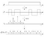
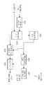
그러면 여기서 도 1을 참조하여 일반적인 TD-SCDMA 방식을 지원하는 통신 시스템에서 1개의 채널화 코드가 사용될 경우의 수신 신호 모델링에 대해서 설명하기로 한다.Herein, with reference to FIG. 1, modeling of a received signal when one channelization code is used in a communication system supporting a general TD-SCDMA scheme will be described.
도 1은 일반적인 TD-SCDMA 방식을 지원하는 통신 시스템에서 1개의 채널화 코드가 사용될 경우의 수신 신호 모델링을 개략적으로 도시한 도면이다.1 is a diagram schematically illustrating modeling of a received signal when one channelization code is used in a communication system supporting a general TD-SCDMA scheme.
도 1을 참조하면, 먼저 신호 송신 장치에서 데이터 심볼 엘리먼트


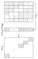
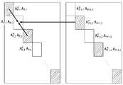
도 2는 일반적인 TD-SCDMA 방식을 지원하는 통신 시스템에서 다수개의 채널화 코드들이 사용될 경우의 송신 신호 모델링을 개략적으로 도시한 도면이다.2 is a diagram schematically illustrating modeling of a transmission signal when a plurality of channelization codes are used in a communication system supporting a general TD-SCDMA scheme.
도 2에는 다수 개, 일 예로 3개의 채널화 코드들이 사용되고, 상기 3개의 채널화 코드들 각각을 기반으로 송신되는 QAM 심볼들의 개수가 N일 경우의 송신 신호 모델링이 도시되어 있다. 특히, 도 3에는 총 3*N개의 QAM 심볼들 중 3*3개의 QAM 심볼들만 도시되어 있음에 유의하여야만 한다.FIG. 2 shows a transmission signal modeling when a plurality of, for example, three channelization codes are used, and the number of QAM symbols transmitted based on each of the three channelization codes is N. In particular, it should be noted that only 3*3 QAM symbols out of a total of 3*N QAM symbols are shown in FIG. 3.
도 2에서는 일반적인 TD-SCDMA 방식을 지원하는 통신 시스템에서 다수개의 채널화 코드들이 사용될 경우의 송신 신호 모델링에 대해서 설명하였으며, 다음으로 도 3을 참조하여 일반적인 TD-SCDMA 방식을 지원하는 통신 시스템에서 행렬V의 구조에 대해서 설명하기로 한다.In FIG. 2, modeling of a transmission signal when a plurality of channelization codes are used in a communication system supporting a general TD-SCDMA method is described. Next, a matrix in a communication system supporting a general TD-SCDMA method is described with reference to FIG. The structure ofV will be described.
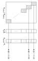
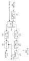
도 3은 일반적인 TD-SCDMA 방식을 지원하는 통신 시스템에서 행렬V의 구조를 개략적으로 도시한 도면이다.3 is a diagram schematically illustrating the structure of a matrixV in a communication system supporting a general TD-SCDMA scheme.
도 3을 참조하면, 먼저 도 1에서 설명한 바와 같은 수신 신호 모델링 및 도 2에서 설명한 바와 같은 송신 신호 모델링을 기반으로 상기 TD-SCDMA 방식을 기반으로 하는 통신 시스템에서 신호 검출기를 위한 시스템 방정식(system equation)을 정의할 수 있다.Referring to FIG. 3, first, based on modeling of a received signal as described in FIG. 1 and modeling of a transmission signal as described in FIG. 2, a system equation for a signal detector in a communication system based on the TD-SCDMA scheme. ) Can be defined.
먼저, 도 1에서 송신 신호, 즉 데이터 심볼d는 채널화 코드c를 기반으로 확산되고, 상기 데이터 심볼d가 상기 채널화 코드c를 기반으로 확산되어 생성된 확산된 데이터 심볼d*c에 대해서는 채널 임펄스 응답h와의 컨벌루션(convolution) 연산이 수행된다. 따라서, 실질적으로 상기 데이터 심볼d가 통과하는 시스템은 채널화 코드c와 채널 임펄스 응답h간의 컨벌루션 형태, 즉 벡터(vector)b로 주어진다. 여기서, k번째 채널화 코드
따라서, 채널 임펄스 응답h0 에 대한b(k)는 하기 수학식 6과 같이 나타낼 수 있다.Therefore,b(k) for the channel impulse responseh0 can be expressed as

상기 수학식 6에서,
또한, 채널 임펄스 응답h1에 대한b(k)는 하기 수학식 7과 같이 나타낼 수 있다.In addition,b(k) for the channel impulse responseh1 can be expressed as Equation 7 below.

상기 수학식 7에서,
따라서, 상기 벡터b(k)를 하나의 열(column)로 간주하면 K개의 채널화 코드들에 대한 벡터b들, 즉 K개의 벡터b들은 1개의 행렬에 포함될 수 있으며, 이 행렬을 행렬V라고 가정하기로 한다. 즉, 상기 행렬V에서는 임의의 채널화 코드c에 대한 벡터b가 1개의 열로 생성되며, 따라서 상기 행렬V는 총 K개의 열들을 포함한다.Therefore, if the vectorb(k) is regarded as one column, vectorsb for K channelization codes, that is, K vectorsb can be included in one matrix, and this matrix is called matrixV. I will assume. That is, in the matrixV , a vectorb for an arbitrary channelization codec is generated as one column, and thus the matrixV includes a total of K columns.
또한, 상기 행렬V는N개의 QAM 심볼들 중 1개의 QAM 심볼에 대하여 정의된다. 따라서, N개의 QAM 심볼들의 위치 전체, 즉 1개의 데이터 블록이 포함하는 전체 QAM 심볼들에 대해서 시스템 행렬(system matrix)을 생성하기 위해서는 상기 N개의 QAM 심볼들에 대한 행렬V들을 캐스캐이딩(cascading)함으로써 상기 총 N개의 행렬V들을 연결하여야 한다.Also, the matrixV isIt is defined for one QAM symbol among N QAM symbols. Therefore, in order to generate a system matrix for all positions of N QAM symbols, that is, all QAM symbols included in one data block, the matrixVs for the N QAM symbols are cascading. ) To connect the total N matrixVs.
이렇게, 상기 N개의 QAM 심볼들에 대한 행렬V들을 캐스캐이딩함으로써 생성된 시스템 행렬을 행렬T라고 가정하기로 한다. 즉, 상기 행렬T는 N개의 QAM 심볼들에 대해 생성된 행렬V들을 포함하는 행렬이다.In this way, it is assumed that the system matrix generated by cascading the matricesV for the N QAM symbols is the matrixT. That is, the matrixT is a matrix including matrixVs generated for N QAM symbols.
이 경우, 가우시안 잡음이 고려되는 시스템 방정식은 하기 수학식 8과 같이 나타낼 수 있다.In this case, the system equation in which Gaussian noise is considered can be expressed as Equation 8 below.

상기 수학식 8에서,n은 가우시안 잡음을 나타내며,y는 상기 가우시안 잡음n을 포함하는 수신 신호 벡터를 나타낸다.In Equation 8,n denotes Gaussian noise, andy denotes a received signal vector including the Gaussian noisen .
또한, 상기 수학식 8에 나타낸 바와 같은, 상기 가우시안 잡음이 고려되는 시스템 방정식에 대한 해는 하기 수학식 9와 같이 나타낼 수 있다.In addition, as shown in Equation 8, a solution to the system equation in which the Gaussian noise is considered can be expressed as Equation 9 below.

상기 수학식 9에서,


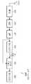
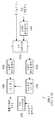
도 3에서는 일반적인 TD-SCDMA 방식을 지원하는 통신 시스템에서 행렬V의 구조에 대해서 설명하였으며, 다음으로 도 4를 참조하여 일반적인 TD-SCDMA 방식을 지원하는 통신 시스템에서 행렬T의 구조에 대해서 설명하기로 한다.In FIG. 3, the structure of the matrixV in the communication system supporting the general TD-SCDMA method has been described, and next, the structure of the matrixT in the communication system supporting the general TD-SCDMA method will be described with reference to FIG. do.
도 4는 일반적인 TD-SCDMA 방식을 지원하는 통신 시스템에서 행렬T의 구조를 개략적으로 도시한 도면이다.4 is a diagram schematically illustrating the structure of a matrixT in a communication system supporting a general TD-SCDMA scheme.
도 4를 참조하면, 상기 행렬T의 크기는 매우 크며, 따라서 수학식 8에서 나타낸 바와 같이
일 예로, 상기 통신 시스템에서 16개의 채널화 코드들이 사용되고, 1개의 데이터 블록이 22개의 QAM 심볼들을 포함할 경우, 상기 행렬T가 포함하는 열들의 개수는 352(=16x22)가 된다. 그런데, 일반적으로 역 행렬의 프로세싱 연산량이 행렬 크기의 세제곱에 비례한다는 것을 고려할 경우, 1개의 데이터 블록을 프로세싱하기 위해 필요로 되는 프로세싱 연산량은 수십 메가 플롭(flop) 이상이 된다.As an example, in the case where 16 channelization codes are used in the communication system and one data block includes 22 QAM symbols, the number of columns included in the matrixT is 352 (=16x22). However, in general, when considering that the processing amount of the inverse matrix is proportional to the cube of the matrix size, the amount of processing required to process one data block is tens of mega-flops or more.
따라서, 이런 프로세싱 연산량을 일반적인 하드웨어(hardware)나 디지털 신호 프로세싱(digital signal processing: DSP, 이하 'DSP'라 칭하기로 한다) 코어(core)를 사용하여 프로세싱하는 것은 거의 불가능하다. 또한, 이런 프로세싱 연산량은 신호 수신 장치의 전력 소모량을 크게 증가시킨다.Therefore, it is almost impossible to process such a processing amount using general hardware or digital signal processing (DSP, hereinafter referred to as'DSP') core. In addition, this amount of processing operation greatly increases the power consumption of the signal receiving device.
따라서, 프로세싱 복잡도 및 프로세싱 연산량을 감소시키면서, 전력 소모량을 감소시키는 신호 검출 방안에 대한 필요성이 대두되고 있다.Accordingly, there is a need for a signal detection method that reduces power consumption while reducing processing complexity and processing computation.
한편, 상기와 같은 정보는 본 발명의 이해를 돕기 위한 백그라운드(background) 정보로서만 제시될 뿐이다. 상기 내용 중 어느 것이라도 본 발명에 관한 종래 기술로서 적용 가능할지 여부에 관해, 어떤 결정도 이루어지지 않았고, 또한 어떤 주장도 이루어지지 않는다.
Meanwhile, the above information is only presented as background information to aid understanding of the present invention. No decision has been made and no argument is made as to whether or not any of the above is applicable as the prior art for the present invention.
본 발명의 일 실시예는 TDD-CDMA 방식을 지원하는 통신 시스템에서 신호 검출 장치 및 방법을 제안한다.An embodiment of the present invention proposes a signal detection apparatus and method in a communication system supporting the TDD-CDMA scheme.
또한, 본 발명의 일 실시예는 TDD-CDMA 방식을 지원하는 통신 시스템에서 프로세싱 복잡도를 감소시키는 것이 가능한 신호 검출 장치 및 방법을 제안한다.In addition, an embodiment of the present invention proposes a signal detection apparatus and method capable of reducing processing complexity in a communication system supporting the TDD-CDMA scheme.
또한, 본 발명의 일 실시예는 TDD-CDMA 방식을 지원하는 통신 시스템에서 프로세싱 연산량을 감소시키는 것이 가능한 신호 검출 장치 및 방법을 제안한다.In addition, an embodiment of the present invention proposes a signal detection apparatus and method capable of reducing a processing amount in a communication system supporting the TDD-CDMA scheme.
또한, 본 발명의 일 실시예는 TDD-CDMA 방식을 지원하는 통신 시스템에서 전력 소모량을 감소시키는 것이 가능한 신호 검출 장치 및 방법을 제안한다.In addition, an embodiment of the present invention proposes a signal detection apparatus and method capable of reducing power consumption in a communication system supporting the TDD-CDMA scheme.
또한, 본 발명의 일 실시예는 TDD-CDMA 방식을 지원하는 통신 시스템에서 성능을 향상시키는 것이 가능한 신호 검출 장치 및 방법을 제안한다.In addition, an embodiment of the present invention proposes a signal detection apparatus and method capable of improving performance in a communication system supporting a TDD-CDMA scheme.
또한, 본 발명의 일 실시예는 TDD-CDMA 방식을 지원하는 통신 시스템에서 비교적 높은 도플러(Doppler) 주파수 환경을 고려한 신호 검출 장치 및 방법을 제안한다.In addition, an embodiment of the present invention proposes a signal detection apparatus and method in consideration of a relatively high Doppler frequency environment in a communication system supporting a TDD-CDMA scheme.
또한, 본 발명의 일 실시예는 TDD-CDMA 방식을 지원하는 통신 시스템에서 보간 방식을 기반으로 생성되는 시스템 행렬을 사용하는 신호 검출 장치 및 방법을 제안한다.
In addition, an embodiment of the present invention proposes a signal detection apparatus and method using a system matrix generated based on an interpolation scheme in a communication system supporting a TDD-CDMA scheme.
본 발명의 일 실시예에서 제안하는 방법은; 시분할 듀플렉싱 코드 분할 다중 접속(time division duplexing-code division multiple access: TDD-CDMA) 방식을 지원하는 통신 시스템에서 신호 수신 장치가 신호를 검출하는 방법에 있어서, 수신 신호에 대한 적어도 하나의 채널 임펄스 응답(channel impulse response)을 기반으로 연산 동작을 수행하여 대각 행렬이 포함하는 블록 대각 행렬들 중 일부의 블록 대각 행렬들을 검출하는 과정과, 상기 검출한 블록 대각 행렬들을 기반으로 상기 블록 대각 행렬들 중 상기 일부의 블록 대각 행렬들을 제외한 나머지 블록 대각 행렬들을 검출하는 과정과, 상기 대각 행렬을 기반으로 상기 수신 신호로부터 신호 송신 장치에서 송신한 변조 심볼들을 추정하는 과정을 포함하며, 블록 대각 행렬은 제1행렬이 포함하는 제2 행렬들 중 어느 한 제2 행렬과 고속 푸리에 변환(fast Fourier transform: FFT) 행렬이 곱해져서 생성되며, 상기 제1 행렬은 제3 행렬들을 포함하는 제4 행렬에 대해 순환 확장 방식이 적용되어 생성되며, 제3 행렬은 상기 변조 심볼들 중 어느 한 변조 심볼에 대해 생성되며, 상기 TDD-CDMA 방식을 지원하는 통신 시스템에서 사용되는 채널화 코드들에 대한 벡터들을 포함하며, 벡터는 상기 채널화 코드들 중 어느 한 채널화 코드와 상기 적어도 하나의 채널 임펄스 응답을 기반으로 생성됨을 특징으로 한다.The method proposed in an embodiment of the present invention is; In a method for a signal receiving device to detect a signal in a communication system supporting a time division duplexing-code division multiple access (TDD-CDMA) method, comprising: at least one channel impulse response to a received signal A process of detecting some block diagonal matrices among block diagonal matrices included in the diagonal matrix by performing an operation based on (channel impulse response), and the process of detecting the block diagonal matrices among the block diagonal matrices based on the detected block diagonal matrices. A process of detecting the remaining block diagonal matrices excluding some of the block diagonal matrices, and a process of estimating modulation symbols transmitted from the signal transmission apparatus from the received signal based on the diagonal matrix, wherein the block diagonal matrix is a first matrix It is generated by multiplying any one of the second matrices included therein by a fast Fourier transform (FFT) matrix, and the first matrix is a cyclic expansion method for a fourth matrix including third matrices Is generated, and a third matrix is generated for any one of the modulation symbols, and includes vectors for channelization codes used in a communication system supporting the TDD-CDMA scheme, and the vector is It is characterized in that it is generated based on one of the channelization codes and the at least one channel impulse response.
본 발명의 일 실시예에서 제안하는 다른 방법은; 시분할 듀플렉싱 코드 분할 다중 접속(time division duplexing-code division multiple access: TDD-CDMA) 방식을 지원하는 통신 시스템에서 신호 수신 장치가 신호를 검출하는 방법에 있어서, 수신 신호에 대한 적어도 하나의 채널 임펄스 응답(channel impulse response)을 기반으로 연산 동작을 수행하여 대각 행렬이 포함하는 블록 대각 행렬들 중 일부의 블록 대각 행렬들과 상기 일부의 블록 대각 행렬들의 허미시안(Hermitian)들이 곱해져서 생성된 행렬 곱들을 검출하는 과정과, 상기 검출한 행렬 곱들을 기반으로 상기 블록 대각 행렬들 중 상기 일부의 블록 대각 행렬들을 제외한 나머지 블록 대각 행렬들과 상기 나머지 블록 대각 행렬들의 허미시안들이 곱해져서 생성된 행렬 곱들을 검출하는 과정과, 상기 행렬 곱들을 기반으로 상기 수신 신호로부터 신호 송신 장치에서 송신한 변조 심볼들을 추정하는 과정을 포함하며, 블록 대각 행렬은 제1행렬이 포함하는 제2 행렬들 중 어느 한 제2 행렬과 고속 푸리에 변환(fast Fourier transform: FFT) 행렬이 곱해져서 생성되며, 상기 제1 행렬은 제3 행렬들을 포함하는 제4 행렬에 대해 순환 확장 방식이 적용되어 생성되며, 제3 행렬은 상기 변조 심볼들 중 어느 한 변조 심볼에 대해 생성되며, 상기 TDD-CDMA 방식을 지원하는 통신 시스템에서 사용되는 채널화 코드들에 대한 벡터들을 포함하며, 벡터는 상기 채널화 코드들 중 어느 한 채널화 코드와 상기 적어도 하나의 채널 임펄스 응답을 기반으로 생성됨을 특징으로 한다.Another method proposed in an embodiment of the present invention is; In a method for a signal receiving device to detect a signal in a communication system supporting a time division duplexing-code division multiple access (TDD-CDMA) method, comprising: at least one channel impulse response to a received signal Matrix products generated by multiplying some of the block diagonal matrices included in the diagonal matrix and Hermitians of the some block diagonal matrices by performing an operation based on the (channel impulse response) Detecting matrix products generated by multiplying the remaining block diagonal matrices excluding some of the block diagonal matrices from the block diagonal matrices and the Hermitians of the remaining block diagonal matrices based on the detection process and the detected matrix products And estimating modulation symbols transmitted by the signal transmission apparatus from the received signal based on the matrix products, wherein the block diagonal matrix is a second matrix among second matrices included in the first matrix. And a fast Fourier transform (FFT) matrix are multiplied and generated, the first matrix is generated by applying a cyclic expansion method to a fourth matrix including third matrices, and a third matrix is the modulation symbol It is generated for any one of the modulation symbols and includes vectors for channelization codes used in a communication system supporting the TDD-CDMA scheme, wherein the vector is one of the channelization codes and the It is characterized in that it is generated based on at least one channel impulse response.
본 발명의 일 실시예에서 제안하는 또 다른 방법은; 시분할 듀플렉싱 코드 분할 다중 접속(time division duplexing-code division multiple access: TDD-CDMA) 방식을 지원하는 통신 시스템에서 신호 수신 장치가 신호를 검출하는 방법에 있어서, 수신 신호에 대한 적어도 하나의 채널 임펄스 응답(channel impulse response)을 기반으로 연산 동작을 수행하여 대각 행렬이 포함하는 블록 대각 행렬들 중 일부의 블록 대각 행렬들과 상기 일부의 블록 대각 행렬들의 허미시안(Hermitian)들이 곱해져서 생성된 행렬 곱들에 대한 분해 행렬들을 검출하는 과정과, 상기 검출한 분해 행렬들을 기반으로 상기 블록 대각 행렬들 중 상기 일부의 블록 대각 행렬들을 제외한 나머지 블록 대각 행렬들과 상기 나머지 블록 대각 행렬들의 허미시안들이 곱해져서 생성된 행렬 곱들에 대한 분해 행렬들을 검출하는 과정과, 상기 분해 행렬들을 기반으로 상기 수신 신호로부터 신호 송신 장치에서 송신한 변조 심볼들을 추정하는 과정을 포함하며, 블록 대각 행렬은 제1행렬이 포함하는 제2 행렬들 중 어느 한 제2 행렬과 고속 푸리에 변환(fast Fourier transform: FFT) 행렬이 곱해져서 생성되며, 상기 제1 행렬은 제3 행렬들을 포함하는 제4 행렬에 대해 순환 확장 방식이 적용되어 생성되며, 제3 행렬은 상기 변조 심볼들 중 어느 한 변조 심볼에 대해 생성되며, 상기 TDD-CDMA 방식을 지원하는 통신 시스템에서 사용되는 채널화 코드들에 대한 벡터들을 포함하며, 벡터는 상기 채널화 코드들 중 어느 한 채널화 코드와 상기 적어도 하나의 채널 임펄스 응답을 기반으로 생성됨을 특징으로 한다.Another method proposed in an embodiment of the present invention is; In a method for a signal receiving device to detect a signal in a communication system supporting a time division duplexing-code division multiple access (TDD-CDMA) method, comprising: at least one channel impulse response to a received signal Matrix products generated by multiplying some of the block diagonal matrices included in the diagonal matrix and Hermitians of the some block diagonal matrices by performing an operation based on the (channel impulse response) The process of detecting the decomposition matrices for and based on the detected decomposition matrices is generated by multiplying the remaining block diagonal matrices excluding the partial block diagonal matrices and the Hermitians of the remaining block diagonal matrices based on the detected decomposition matrices. A process of detecting decomposition matrices for matrix products, and a process of estimating modulation symbols transmitted by a signal transmission apparatus from the received signal based on the decomposition matrices, wherein the block diagonal matrix is a second matrix included in the first matrix. Any one of the matrices is generated by multiplying a second matrix and a fast Fourier transform (FFT) matrix, and the first matrix is generated by applying a cyclic expansion scheme to a fourth matrix including third matrices. , A third matrix is generated for any one of the modulation symbols, and includes vectors for channelization codes used in a communication system supporting the TDD-CDMA scheme, the vector being the channelization codes It is characterized in that it is generated based on one of the channelization codes and the at least one channel impulse response.
본 발명의 일 실시예에서 제안하는 장치는; 시분할 듀플렉싱 코드 분할 다중 접속(time division duplexing-code division multiple access: TDD-CDMA) 방식을 지원하는 통신 시스템에서 신호 수신 장치에 있어서, 수신 신호에 대한 적어도 하나의 채널 임펄스 응답(channel impulse response)을 기반으로 연산 동작을 수행하여 대각 행렬이 포함하는 블록 대각 행렬들 중 일부의 블록 대각 행렬들을 검출하는 동작과, 상기 검출한 블록 대각 행렬들을 기반으로 상기 블록 대각 행렬들 중 상기 일부의 블록 대각 행렬들을 제외한 나머지 블록 대각 행렬들을 검출하는 동작과, 상기 대각 행렬을 기반으로 상기 수신 신호로부터 신호 송신 장치에서 송신한 변조 심볼들을 추정하는 동작을 수행하는 조인트(joint) 검출기를 포함하며, 블록 대각 행렬은 제1행렬이 포함하는 제2 행렬들 중 어느 한 제2 행렬과 고속 푸리에 변환(fast Fourier transform: FFT) 행렬이 곱해져서 생성되며, 상기 제1 행렬은 제3 행렬들을 포함하는 제4 행렬에 대해 순환 확장 방식이 적용되어 생성되며, 제3 행렬은 상기 변조 심볼들 중 어느 한 변조 심볼에 대해 생성되며, 상기 TDD-CDMA 방식을 지원하는 통신 시스템에서 사용되는 채널화 코드들에 대한 벡터들을 포함하며, 벡터는 상기 채널화 코드들 중 어느 한 채널화 코드와 상기 적어도 하나의 채널 임펄스 응답을 기반으로 생성됨을 특징으로 한다.An apparatus proposed in an embodiment of the present invention includes; In a signal receiving apparatus in a communication system supporting a time division duplexing-code division multiple access (TDD-CDMA) method, at least one channel impulse response to a received signal is An operation of detecting some of the block diagonal matrices among the block diagonal matrices included in the diagonal matrix by performing an operation operation on the basis of the operation, and the partial block diagonal matrices among the block diagonal matrices based on the detected block diagonal matrices. And a joint detector performing an operation of detecting the remaining block diagonal matrices, and estimating modulation symbols transmitted from the signal transmission apparatus from the received signal based on the diagonal matrix, wherein the block diagonal matrix is It is generated by multiplying any one of the second matrices included in the first matrix by a fast Fourier transform (FFT) matrix, and the first matrix is circulated for a fourth matrix including third matrices. It is generated by applying an extension scheme, and a third matrix is generated for any one of the modulation symbols, and includes vectors for channelization codes used in a communication system supporting the TDD-CDMA scheme, A vector is characterized in that it is generated based on one of the channelization codes and the at least one channel impulse response.
본 발명의 일 실시예에서 제안하는 다른 장치는; 시분할 듀플렉싱 코드 분할 다중 접속(time division duplexing-code division multiple access: TDD-CDMA) 방식을 지원하는 통신 시스템에서 신호 수신 장치에 있어서, 수신 신호에 대한 적어도 하나의 채널 임펄스 응답(channel impulse response)을 기반으로 연산 동작을 수행하여 대각 행렬이 포함하는 블록 대각 행렬들 중 일부의 블록 대각 행렬들과 상기 일부의 블록 대각 행렬들의 허미시안(Hermitian)들이 곱해져서 생성된 행렬 곱들을 검출하는 동작과, 상기 검출한 행렬 곱들을 기반으로 상기 블록 대각 행렬들 중 상기 일부의 블록 대각 행렬들을 제외한 나머지 블록 대각 행렬들과 상기 나머지 블록 대각 행렬들의 허미시안들이 곱해져서 생성된 행렬 곱들을 검출하는 동작과, 상기 행렬 곱들을 기반으로 상기 수신 신호로부터 신호 송신 장치에서 송신한 변조 심볼들을 추정하는 동작을 수행하는 조인트(joint) 검출기를 포함하며, 블록 대각 행렬은 제1행렬이 포함하는 제2 행렬들 중 어느 한 제2 행렬과 고속 푸리에 변환(fast Fourier transform: FFT) 행렬이 곱해져서 생성되며, 상기 제1 행렬은 제3 행렬들을 포함하는 제4 행렬에 대해 순환 확장 방식이 적용되어 생성되며, 제3 행렬은 상기 변조 심볼들 중 어느 한 변조 심볼에 대해 생성되며, 상기 TDD-CDMA 방식을 지원하는 통신 시스템에서 사용되는 채널화 코드들에 대한 벡터들을 포함하며, 벡터는 상기 채널화 코드들 중 어느 한 채널화 코드와 상기 적어도 하나의 채널 임펄스 응답을 기반으로 생성됨을 특징으로 한다.Another device proposed in an embodiment of the present invention is; In a signal receiving apparatus in a communication system supporting a time division duplexing-code division multiple access (TDD-CDMA) method, at least one channel impulse response to a received signal is Detecting matrix products generated by multiplying some block diagonal matrices among block diagonal matrices included in the diagonal matrix and Hermitians of the some block diagonal matrices by performing an operation operation based on the calculation, and the Detecting matrix products generated by multiplying the remaining block diagonal matrices excluding some of the block diagonal matrices from the block diagonal matrices based on the detected matrix products and the Hermitians of the remaining block diagonal matrices; and the matrix And a joint detector for estimating modulation symbols transmitted from the signal transmission apparatus from the received signal based on the products, wherein the block diagonal matrix is one of second matrices included in the first matrix. 2 matrices are multiplied by a fast Fourier transform (FFT) matrix, and the first matrix is generated by applying a cyclic expansion method to a fourth matrix including third matrices, and the third matrix is the It is generated for any one of the modulation symbols and includes vectors for channelization codes used in a communication system supporting the TDD-CDMA scheme, and the vector is any one of the channelization codes And the at least one channel impulse response.
본 발명의 일 실시예에서 제안하는 또 다른 장치는; 시분할 듀플렉싱 코드 분할 다중 접속(time division duplexing-code division multiple access: TDD-CDMA) 방식을 지원하는 통신 시스템에서 신호 수신 장치에 있어서, 수신 신호에 대한 적어도 하나의 채널 임펄스 응답(channel impulse response)을 기반으로 연산 동작을 수행하여 대각 행렬이 포함하는 블록 대각 행렬들 중 일부의 블록 대각 행렬들과 상기 일부의 블록 대각 행렬들의 허미시안(Hermitian)들이 곱해져서 생성된 행렬 곱들에 대한 분해 행렬들을 검출하는 동작과, 상기 검출한 분해 행렬들을 기반으로 상기 블록 대각 행렬들 중 상기 일부의 블록 대각 행렬들을 제외한 나머지 블록 대각 행렬들과 상기 나머지 블록 대각 행렬들의 허미시안들이 곱해져서 생성된 행렬 곱들에 대한 분해 행렬들을 검출하는 동작과, 상기 분해 행렬들을 기반으로 상기 수신 신호로부터 신호 송신 장치에서 송신한 변조 심볼들을 추정하는 동작을 수행하는 조인트(joint) 검출기를 포함하며, 블록 대각 행렬은 제1행렬이 포함하는 제2 행렬들 중 어느 한 제2 행렬과 고속 푸리에 변환(fast Fourier transform: FFT) 행렬이 곱해져서 생성되며, 상기 제1 행렬은 제3 행렬들을 포함하는 제4 행렬에 대해 순환 확장 방식이 적용되어 생성되며, 제3 행렬은 상기 변조 심볼들 중 어느 한 변조 심볼에 대해 생성되며, 상기 TDD-CDMA 방식을 지원하는 통신 시스템에서 사용되는 채널화 코드들에 대한 벡터들을 포함하며, 벡터는 상기 채널화 코드들 중 어느 한 채널화 코드와 상기 적어도 하나의 채널 임펄스 응답을 기반으로 생성됨을 특징으로 한다.Another device proposed in an embodiment of the present invention is; In a signal receiving apparatus in a communication system supporting a time division duplexing-code division multiple access (TDD-CDMA) method, at least one channel impulse response to a received signal is Detecting decomposition matrices for matrix products generated by multiplying some of the block diagonal matrices included in the diagonal matrix and Hermitians of the some block diagonal matrices by performing an operation operation based on A decomposition matrix for matrix products generated by multiplying the operation and the detected decomposition matrices by multiplying the remaining block diagonal matrices excluding the partial block diagonal matrices from the remaining block diagonal matrices and the Hermitians of the remaining block diagonal matrices And a joint detector performing an operation of estimating modulation symbols transmitted from the signal transmission apparatus from the received signal based on the decomposition matrices, and the block diagonal matrix is included in the first matrix. One of the second matrices is generated by multiplying a second matrix and a fast Fourier transform (FFT) matrix, and the first matrix is a cyclic expansion method applied to a fourth matrix including third matrices. Is generated, and a third matrix is generated for one of the modulation symbols, and includes vectors for channelization codes used in a communication system supporting the TDD-CDMA scheme, and the vector is the channelization It is characterized in that it is generated based on a channelization code among codes and the at least one channel impulse response.
본 발명의 다른 측면들과, 이득들 및 핵심적인 특징들은 부가 도면들과 함께 처리되고, 본 발명의 바람직한 실시예들을 게시하는, 하기의 구체적인 설명으로부터 해당 기술 분야의 당업자에게 자명할 것이다.Other aspects, benefits and key features of the present invention will be apparent to those skilled in the art from the following detailed description, which is handled with additional drawings, and posts preferred embodiments of the present invention.
하기의 본 게시의 구체적인 설명 부분을 처리하기 전에, 이 특허 문서를 통해 사용되는 특정 단어들 및 구문들에 대한 정의들을 설정하는 것이 효과적일 수 있다: 상기 용어들 “포함하다(include)” 및 “포함하다(comprise)”과 그 파생어들은 한정없는 포함을 의미하며; 상기 용어 “혹은(or)”은 포괄적이고 ‘및/또는’을 의미하고; 상기 구문들 “~와 연관되는(associated with)” 및 ““~와 연관되는(associated therewith)”과 그 파생어들은 포함하고(include), ~내에 포함되고(be included within), ~와 서로 연결되고(interconnect with), 포함하고(contain), ~내에 포함되고(be contained within), ~에 연결하거나 혹은 ~와 연결하고(connect to or with), ~에 연결하거나 혹은 ~와 연결하고(couple to or with), ~와 통신 가능하고(be communicable with), ~와 협조하고(cooperate with), 인터리빙하고(interleave), 병치하고(juxtapose), ~로 가장 근접하고(be proximate to), ~로 ~할 가능성이 크거나 혹은 ~와 ~할 가능성이 크고(be bound to or with), 가지고(have), 소유하고(have a property of) 등과 같은 것을 의미하고; 상기 용어 “제어기”는 적어도 하나의 동작을 제어하는 임의의 디바이스, 시스템, 혹은 그 부분을 의미하고, 상기와 같은 디바이스는 하드웨어, 펌웨어 혹은 소프트웨어, 혹은 상기 하드웨어, 펌웨어 혹은 소프트웨어 중 적어도 2개의 몇몇 조합에서 구현될 수 있다. 어떤 특정 제어기와 연관되는 기능성이라도 집중화되거나 혹은 분산될 수 있으며, 국부적이거나 원격적일 수도 있다는 것에 주의해야만 할 것이다. 특정 단어들 및 구문들에 대한 정의들은 이 특허 문서에 걸쳐 제공되고, 해당 기술 분야의 당업자는 많은 경우, 대부분의 경우가 아니라고 해도, 상기와 같은 정의들이 종래 뿐만 아니라 상기와 같이 정의된 단어들 및 구문들의 미래의 사용들에도 적용된다는 것을 이해해야만 할 것이다.
It may be effective to establish definitions for specific words and phrases used throughout this patent document before proceeding with the specific description portion of this publication below: the terms “include” and “ "Comprise" and its derivatives mean inclusion without limitation; The term “or” is inclusive and means “and/or”; The above phrases "associated with" and "associated therewith" and their derivatives include, be included within, and are linked to (interconnect with), contain, be contained within, connect to or with, connect to, or couple to or with), be communicable with, cooperate with, interleave, juxtapose, be proximate to, and be proximate to Means something like be bound to or with, have, have a property of, etc.; The term “controller” refers to any device, system, or part that controls at least one operation, and such devices include hardware, firmware, or software, or some combination of at least two of the hardware, firmware, or software. Can be implemented in It should be noted that the functionality associated with any particular controller can be centralized or distributed, and can be local or remote. Definitions for specific words and phrases are provided throughout this patent document, and those skilled in the art, in many cases, if not in most cases, such definitions are not only conventional, but also words and phrases defined as above. It will have to be understood that it also applies to future uses of the phrases.
본 발명의 일 실시예는 TDD-CDMA 방식을 지원하는 통신 시스템에서 프로세싱 복잡도를 감소시키는 것이 가능하도록 신호를 검출하는 것을 가능하게 한다는 효과가 있다.An embodiment of the present invention has the effect of enabling signal detection to be possible to reduce processing complexity in a communication system supporting the TDD-CDMA scheme.
또한, 본 발명의 일 실시예는 TDD-CDMA 방식을 지원하는 통신 시스템에서 프로세싱 연산량을 감소시키는 것이 가능하도록 신호를 검출하는 것을 가능하게 한다는 효과가 있다.In addition, an embodiment of the present invention has the effect of enabling signal detection to be possible to reduce a processing amount in a communication system supporting the TDD-CDMA scheme.
또한, 본 발명의 일 실시예는 TDD-CDMA 방식을 지원하는 통신 시스템에서 전력 소모량을 감소시키는 것이 가능하도록 신호를 검출하는 것을 가능하게 한다는 효과가 있다.In addition, an embodiment of the present invention has the effect of enabling signal detection so as to reduce power consumption in a communication system supporting the TDD-CDMA scheme.
또한, 본 발명의 일 실시예는 TDD-CDMA 방식을 지원하는 통신 시스템에서 성능을 향상시키는 것이 가능하도록 신호를 검출하는 것을 가능하게 한다는 효과가 있다.In addition, an embodiment of the present invention has the effect of enabling signal detection so as to improve performance in a communication system supporting the TDD-CDMA scheme.
또한, 본 발명의 일 실시예는 TDD-CDMA 방식을 지원하는 통신 시스템에서 높은 도플러 주파수 환경을 고려하는 것이 가능하도록 신호를 검출하는 것을 가능하게 한다는 효과가 있다.In addition, an embodiment of the present invention has the effect of enabling signal detection so that it is possible to consider a high Doppler frequency environment in a communication system supporting the TDD-CDMA scheme.
또한, 본 발명의 일 실시예는 TDD-CDMA 방식을 지원하는 통신 시스템에서 보간 방식을 기반으로 생성되는 시스템 행렬을 사용하여 신호를 검출하는 것을 가능하게 한다는 효과가 있다.
In addition, an embodiment of the present invention has an effect that it is possible to detect a signal using a system matrix generated based on an interpolation method in a communication system supporting the TDD-CDMA method.
본 발명의 특정한 바람직한 실시예들의 상기에서 설명한 바와 같은 또한 다른 측면들과, 특징들 및 이득들은 첨부 도면들과 함께 처리되는 하기의 설명으로부터 보다 명백하게 될 것이다:
도 1은 일반적인 TD-SCDMA 방식을 지원하는 통신 시스템에서 1개의 채널화 코드가 사용될 경우의 수신 신호 모델링을 개략적으로 도시한 도면이다;
도 2는 일반적인 TD-SCDMA 방식을 지원하는 통신 시스템에서 다수개의 채널화 코드들이 사용될 경우의 송신 신호 모델링을 개략적으로 도시한 도면이다;
도 3은 일반적인 TD-SCDMA 방식을 지원하는 통신 시스템에서 행렬V의 구조를 개략적으로 도시한 도면이다;
도 4는 일반적인 TD-SCDMA 방식을 지원하는 통신 시스템에서 행렬T의 구조를 개략적으로 도시한 도면이다;
도 5는 본 발명의 일 실시예에 따른 TDD-CDMA 방식을 지원하는 통신 시스템에서 사용되는 순환 확장 방식의 일 예를 개략적으로 도시한 도면이다;
도 6은 본 발명의 일 실시예에 따른 TDD-CDMA 방식을 지원하는 통신 시스템에서 행렬C에 대한 블록 대각화 과정을 개략적으로 도시한 도면이다;
도 7은 본 발명의 일 실시예에 따른 TDD-CDMA 방식을 지원하는 통신 시스템에서 행렬
도 8은 본 발명의 일 실시예에 따른 TDD-CDMA 방식을 지원하는 통신 시스템에서 신호 수신 장치의 내부 구조를 개략적으로 도시한 도면이다;
도 9는 도 8의 조인트 검출기(821)의 내부 구조를 개략적으로 도시한 도면이다;
도 10은 본 발명의 일 실시예에 따른 TDD-CDMA 방식을 지원하는 통신 시스템에서 시간 슬럿의 구조를 개략적으로 도시한 도면이다;
도 11은 본 발명의 일 실시예에 따른 TDD-CDMA 방식을 지원하는 통신 시스템에서 제1 JD 방식에서 수행되는 블록 대각 행렬들에 대한 보간 과정을 개략적으로 도시한 도면이다;
도 12는 본 발명의 일 실시예에 따른 TDD-CDMA 방식을 지원하는 통신 시스템에서 제1 JD 방식을 기반으로 하는 조인트 검출기의 내부 구조를 개략적으로 도시한 도면이다;
도 13은 본 발명의 일 실시예에 따른 TDD-CDMA 방식을 지원하는 통신 시스템에서 제2 JD 방식에서 수행되는 블록 대각 행렬들간의 곱셈에 대한 보간 과정을 개략적으로 도시한 도면이다;
도 14는 본 발명의 일 실시예에 따른 TDD-CDMA 방식을 지원하는 통신 시스템에서 제2 JD 방식을 기반으로 하는 조인트 검출기의 내부 구조를 개략적으로 도시한 도면이다;
도 15는 본 발명의 일 실시예에 따른 TDD-CDMA 방식을 지원하는 통신 시스템에서 제3 JD 방식에서 수행되는 촐레스키 분해 행렬들에 대한 보간 과정을 개략적으로 도시한 도면이다;
도 16은 본 발명의 일 실시예에 따른 TDD-CDMA 방식을 지원하는 통신 시스템에서 제3 JD 방식을 기반으로 하는 조인트 검출기의 내부 구조를 개략적으로 도시한 도면이다;
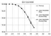
도 17은 본 발명의 일 실시예에 따른 TDD-CDMA 방식을 지원하는 통신 시스템에서 BLER 성능의 일 예를 개략적으로 도시한 도면이다;
도 18은 본 발명의 일 실시예에 따른 TDD-CDMA 방식을 지원하는 통신 시스템에서 BLER 성능의 다른 예를 개략적으로 도시한 도면이다;
도 19는 본 발명의 일 실시예에 따른 TDD-CDMA 방식을 지원하는 통신 시스템에서 BLER 성능의 또 다른 예를 개략적으로 도시한 도면이다;
도 20은 본 발명의 일 실시예에 따른 TDD-CDMA 방식을 지원하는 통신 시스템에서 BLER 성능의 또 다른 예를 개략적으로 도시한 도면이다.
상기 도면들을 통해, 유사 참조 번호들은 동일한 혹은 유사한 엘리먼트들과, 특징들 및 구조들을 도시하기 위해 사용된다는 것에 유의해야만 한다.Other aspects, features and benefits as described above of certain preferred embodiments of the present invention will become more apparent from the following description taken in conjunction with the accompanying drawings:
1 is a diagram schematically showing modeling of a received signal when one channelization code is used in a communication system supporting a general TD-SCDMA scheme;
FIG. 2 is a diagram schematically illustrating a transmission signal modeling when a plurality of channelization codes are used in a communication system supporting a general TD-SCDMA scheme;
3 is a diagram schematically illustrating a structure of a matrixV in a communication system supporting a general TD-SCDMA scheme;
4 is a diagram schematically illustrating a structure of a matrixT in a communication system supporting a general TD-SCDMA scheme;
5 is a diagram schematically illustrating an example of a cyclic expansion scheme used in a communication system supporting a TDD-CDMA scheme according to an embodiment of the present invention;
6 is a diagram schematically illustrating a block diagonalization process for a matrixC in a communication system supporting a TDD-CDMA scheme according to an embodiment of the present invention;
7 is a matrix in a communication system supporting a TDD-CDMA scheme according to an embodiment of the present invention
8 is a diagram schematically illustrating an internal structure of a signal receiving apparatus in a communication system supporting a TDD-CDMA scheme according to an embodiment of the present invention;
9 is a diagram schematically showing the internal structure of the
10 is a diagram schematically showing a structure of a time slot in a communication system supporting a TDD-CDMA scheme according to an embodiment of the present invention;
11 is a diagram schematically illustrating an interpolation process for block diagonal matrices performed in a first JD scheme in a communication system supporting a TDD-CDMA scheme according to an embodiment of the present invention;
12 is a diagram schematically illustrating an internal structure of a joint detector based on a first JD scheme in a communication system supporting a TDD-CDMA scheme according to an embodiment of the present invention;
13 is a diagram schematically illustrating an interpolation process for multiplication between block diagonal matrices performed in a second JD scheme in a communication system supporting a TDD-CDMA scheme according to an embodiment of the present invention;
14 is a diagram schematically illustrating an internal structure of a joint detector based on a second JD scheme in a communication system supporting a TDD-CDMA scheme according to an embodiment of the present invention;
15 is a diagram schematically illustrating an interpolation process for Cholesky decomposition matrices performed in a third JD scheme in a communication system supporting a TDD-CDMA scheme according to an embodiment of the present invention;
16 is a diagram schematically illustrating an internal structure of a joint detector based on a third JD scheme in a communication system supporting a TDD-CDMA scheme according to an embodiment of the present invention;
17 is a diagram schematically illustrating an example of BLER performance in a communication system supporting a TDD-CDMA scheme according to an embodiment of the present invention;
18 is a diagram schematically illustrating another example of BLER performance in a communication system supporting a TDD-CDMA scheme according to an embodiment of the present invention;
19 is a diagram schematically showing another example of BLER performance in a communication system supporting a TDD-CDMA scheme according to an embodiment of the present invention;
20 is a diagram schematically illustrating another example of BLER performance in a communication system supporting a TDD-CDMA scheme according to an embodiment of the present invention.
It should be noted that throughout the drawings, like reference numbers are used to show the same or similar elements, features, and structures.
이하, 본 발명의 실시 예들을 첨부한 도면들을 참조하여 상세히 설명한다. 그리고, 하기에서는 본 발명의 실시예들에 따른 동작을 이해하는데 필요한 부분만이 설명되며, 그 이외의 부분의 설명은 본 발명의 요지를 흩트리지 않도록 생략될 것이라는 것을 유의하여야 한다. 그리고 후술되는 용어들은 본 발명의 실시예들에서의 기능을 고려하여 정의된 용어들로서 이는 사용자, 운용자의 의도 또는 관례 등에 따라 달라질 수 있다. 그러므로 그 정의는 본 명세서 전반에 걸친 내용을 토대로 내려져야 할 것이다.Hereinafter, embodiments of the present invention will be described in detail with reference to the accompanying drawings. In addition, it should be noted that only parts necessary to understand the operation according to the embodiments of the present invention will be described below, and descriptions of other parts will be omitted so as not to obscure the gist of the present invention. In addition, terms to be described later are terms defined in consideration of functions in the embodiments of the present invention, which may vary according to the intention or custom of users or operators. Therefore, the definition should be made based on the contents throughout this specification.
본 발명은 다양한 변경을 가할 수 있고 여러 가지 실시 예들을 가질 수 있는 바, 특정 실시 예들을 도면들에 예시하여 상세하게 설명한다. 그러나, 이는 본 발명을 특정한 실시 형태에 대해 한정하려는 것이 아니며, 본 발명의 사상 및 기술 범위에 포함되는 모든 변경, 균등물 내지 대체물을 포함하는 것으로 이해되어야 한다.The present invention will be described in detail by exemplifying specific embodiments in the drawings as various changes may be made and various embodiments may be provided. However, this is not intended to limit the present invention to a specific embodiment, it is to be understood to include all changes, equivalents, and substitutes included in the spirit and scope of the present invention.
또한, 본 명세서에서 명백하게 다른 내용을 지시하지 않는 “한”과, “상기”와 같은 단수 표현들은 복수 표현들을 포함한다는 것이 이해될 수 있을 것이다. 따라서, 일 예로, “컴포넌트 표면(component surface)”은 하나 혹은 그 이상의 컴포넌트 표면들을 포함한다.In addition, it will be understood that singular expressions such as “han” and “above”, which do not clearly indicate otherwise, include plural expressions. Thus, as an example, a "component surface" includes one or more component surfaces.
또한, 제1, 제2 등과 같이 서수를 포함하는 용어는 다양한 구성요소들을 설명하는데 사용될 수 있지만, 상기 구성요소들은 상기 용어들에 의해 한정되지는 않는다. 상기 용어들은 하나의 구성요소를 다른 구성요소로부터 구별하는 목적으로만 사용된다. 예를 들어, 본 발명의 권리 범위를 벗어나지 않으면서 제1 구성요소는 제2 구성요소로 명명될 수 있고, 유사하게 제2 구성요소도 제1 구성요소로 명명될 수 있다. 및/또는 이라는 용어는 복수의 관련된 기재된 항목들의 조합 또는 복수의 관련된 기재된 항목들 중의 어느 항목을 포함한다.In addition, terms including ordinal numbers such as first and second may be used to describe various elements, but the elements are not limited by the terms. These terms are used only for the purpose of distinguishing one component from another component. For example, without departing from the scope of the present invention, a first element may be referred to as a second element, and similarly, a second element may be referred to as a first element. The term and/or includes a combination of a plurality of related listed items or any of a plurality of related listed items.
또한, 본 명세서에서 사용한 용어는 단지 특정한 실시 예를 설명하기 위해 사용된 것으로, 본 발명을 한정하려는 의도가 아니다. 단수의 표현은 문맥상 명백하게 다르게 뜻하지 않는 한, 복수의 표현을 포함한다. 본 명세서에서, "포함하다" 또는 "가지다" 등의 용어는 명세서상에 기재된 특징, 숫자, 단계, 동작, 구성요소, 부품 또는 이들을 조합한 것이 존재함을 지정하려는 것이지, 하나 또는 그 이상의 다른 특징들이나 숫자, 단계, 동작, 구성요소, 부품 또는 이들을 조합한 것들의 존재 또는 부가 가능성을 미리 배제하지 않는 것으로 이해되어야 한다.In addition, terms used in the present specification are only used to describe specific embodiments, and are not intended to limit the present invention. Singular expressions include plural expressions unless the context clearly indicates otherwise. In this specification, terms such as "comprise" or "have" are intended to designate the presence of features, numbers, steps, actions, components, parts, or a combination thereof described in the specification, but one or more other features. It is to be understood that the presence or addition of elements or numbers, steps, actions, components, parts, or combinations thereof, does not preclude in advance.
또한, 본 발명의 실시예들에서, 별도로 다르게 정의되지 않는 한, 기술적이거나 과학적인 용어를 포함해서 여기서 사용되는 모든 용어들은 본 발명이 속하는 기술 분야에서 통상의 지식을 가진 자에 의해 일반적으로 이해되는 것과 동일한 의미를 가지고 있다. 일반적으로 사용되는 사전에 정의되어 있는 것과 같은 용어들은 관련 기술의 문맥 상 가지는 의미와 일치하는 의미를 가지는 것으로 해석되어야 하며, 본 발명의 실시예에서 명백하게 정의하지 않는 한, 이상적이거나 과도하게 형식적인 의미로 해석되지 않는다.In addition, in the embodiments of the present invention, unless otherwise defined, all terms used herein including technical or scientific terms are commonly understood by those of ordinary skill in the art to which the present invention belongs. It has the same meaning as. Terms as defined in a commonly used dictionary should be interpreted as having a meaning consistent with the meaning in the context of the related technology, and unless explicitly defined in the embodiments of the present invention, an ideal or excessively formal meaning Is not interpreted as.
본 발명의 다양한 실시예들에 따르면, 전자 디바이스는 통신 기능을 포함할 수 있다. 일 예로, 전자 디바이스는 스마트 폰(smart phone)과, 태블릿(tablet) 개인용 컴퓨터(personal computer: PC, 이하 'PC'라 칭하기로 한다)와, 이동 전화기와, 화상 전화기와, 전자책 리더(e-book reader)와, 데스크 탑(desktop) PC와, 랩탑(laptop) PC와, 넷북(netbook) PC와, 개인용 복합 단말기(personal digital assistant: PDA, 이하 'PDA'라 칭하기로 한다)와, 휴대용 멀티미디어 플레이어(portable multimedia player: PMP, 이하 'PMP'라 칭하기로 한다)와, 엠피3 플레이어(mp3 player)와, 이동 의료 디바이스와, 카메라와, 웨어러블 디바이스(wearable device)(일 예로, 헤드-마운티드 디바이스(head-mounted device: HMD, 일 예로 'HMD'라 칭하기로 한다)와, 전자 의류와, 전자 팔찌와, 전자 목걸이와, 전자 앱세서리(appcessory)와, 전자 문신, 혹은 스마트 워치(smart watch) 등이 될 수 있다.According to various embodiments of the present invention, an electronic device may include a communication function. For example, the electronic device includes a smart phone, a tablet personal computer (PC, hereinafter referred to as'PC'), a mobile phone, a video phone, and an e-book reader (e -book reader), desktop PC, laptop PC, netbook PC, personal digital assistant (PDA, hereinafter referred to as'PDA'), portable Multimedia player (portable multimedia player: PMP, hereinafter referred to as'PMP'), mp3 player, mobile medical device, camera, wearable device (for example, head-mounted Device (head-mounted device: HMD, for example, to be referred to as'HMD'), electronic clothing, electronic bracelet, electronic necklace, electronic appcessory, electronic tattoo, or smart watch ), etc.
본 발명의 다양한 실시예들에 따르면, 전자 디바이스는 통신 기능을 가지는 스마트 가정용 기기(smart home appliance)가 될 수 있다. 일 예로, 상기 스마트 가정용 기기는 텔레비젼과, 디지털 비디오 디스크(digital video disk: DVD, 이하 'DVD'라 칭하기로 한다) 플레이어와, 오디오와, 냉장고와, 에어 컨디셔너와, 진공 청소기와, 오븐과, 마이크로웨이브 오븐과, 워셔와, 드라이어와, 공기 청정기와, 셋-탑 박스(set-top box)와, TV 박스 (일 예로, Samsung HomeSyncTM, Apple TVTM, 혹은 Google TVTM)와, 게임 콘솔(gaming console)과, 전자 사전과, 캠코더와, 전자 사진 프레임 등이 될 수 있다.According to various embodiments of the present disclosure, the electronic device may be a smart home appliance having a communication function. For example, the smart home appliance includes a television department, a digital video disk (DVD, hereinafter referred to as'DVD') player, an audio device, a refrigerator, an air conditioner, a vacuum cleaner, an oven, and Microwave oven, washer, dryer, air purifier, set-top box, TV box (eg, Samsung HomeSyncTM , Apple TVTM , or Google TVTM ), game console (gaming console), electronic dictionary, camcorder, electronic photo frame, etc.
본 발명의 다양한 실시예들에 따르면, 전자 디바이스는 의료 기기(일 예로, 자기 공명 혈관 조영술(magnetic resonance angiography: MRA, 이하 'MRA'라 칭하기로 한다) 디바이스와, 자기 공명 화상법(magnetic resonance imaging: MRI, 이하 'MRI'라 칭하기로 한다)과, 컴퓨터 단층 촬영(computed tomography: CT, 이하 'CT'라 칭하기로 한다) 디바이스와, 촬상 디바이스, 혹은 초음파 디바이스)와, 네비게이션(navigation) 디바이스와, 전세계 위치 시스템(global positioning system: GPS, 이하 'GPS라 칭하기로 한다) 수신기와, 사고 기록 장치(event data recorder: EDR, 이하 'EDR'이라 칭하기로 한다)와, 비행 기록 장치(flight data recorder: FDR, 이하 'FDR'이라 칭하기로 한다)와, 자동차 인포테인먼트 디바이스(automotive infotainment device)와, 항해 전자 디바이스(일 예로, 항해 네비게이션 디바이스, 자이로스코프(gyroscope), 혹은 나침반)와, 항공 전자 디바이스와, 보안 디바이스와, 산업용 혹은 소비자용 로봇(robot) 등이 될 수 있다.According to various embodiments of the present invention, the electronic device includes a medical device (for example, magnetic resonance angiography (MRA, hereinafter referred to as'MRA')), and magnetic resonance imaging. : MRI, hereinafter referred to as'MRI'), computed tomography (CT, hereinafter referred to as'CT') device, imaging device, or ultrasound device), and navigation device , A global positioning system (GPS, hereinafter referred to as'GPS') receiver, an event data recorder (EDR, hereinafter referred to as'EDR'), and a flight data recorder : FDR, hereinafter referred to as'FDR'), an automotive infotainment device, a navigation electronic device (for example, a navigation navigation device, a gyroscope, or a compass), an avionics device , Security devices, and industrial or consumer robots.
본 발명의 다양한 실시예들에 따르면, 전자 디바이스는 통신 기능을 포함하는, 가구와, 빌딩/구조의 일부와, 전자 보드와, 전자 서명 수신 디바이스와, 프로젝터와, 다양한 측정 디바이스들(일 예로, 물과, 전기와, 가스 혹은 전자기 파 측정 디바이스들) 등이 될 수 있다.According to various embodiments of the present invention, the electronic device includes furniture, a part of a building/structure, an electronic board, an electronic signature receiving device, a projector, and various measuring devices (for example, including a communication function). Water, electricity, gas or electromagnetic wave measuring devices), etc.
본 발명의 다양한 실시예들에 따르면, 전자 디바이스는 상기에서 설명한 바와 같은 디바이스들의 조합이 될 수 있다. 또한, 본 발명의 바람직한 실시예들에 따른 전자 디바이스는 상기에서 설명한 바와 같은 디바이스에 한정되는 것이 아니라는 것은 당업자에게 자명할 것이다.According to various embodiments of the present invention, the electronic device may be a combination of devices as described above. Further, it will be apparent to those skilled in the art that the electronic device according to the preferred embodiments of the present invention is not limited to the device as described above.
본 발명의 다양한 실시예들에 따르면, 신호 수신 장치는 일 예로 전자 디바이스가 될 수 있다.According to various embodiments of the present disclosure, the signal receiving apparatus may be an electronic device, for example.
또한, 본 발명의 다양한 실시예들에 따르면, 신호 송신 장치는 일 예로 기지국(base station: BS)이 될 수 있고, 신호 수신 장치는 일 예로 이동 단말기(mobile station: MS)가 될 수 있다.Further, according to various embodiments of the present invention, the signal transmission apparatus may be, for example, a base station (BS), and the signal reception apparatus may be, for example, a mobile station (MS).
본 발명의 일 실시예는 시분할 듀플렉싱 코드 분할 다중 접속(time division duplexing-code division multiple access: TDD-CDMA, 이하 'TDD-CDMA'라 칭하기로 한다) 방식을 지원하는 통신 시스템에서 신호 검출 장치 및 방법을 제안한다.An embodiment of the present invention is a signal detection apparatus in a communication system supporting a time division duplexing-code division multiple access (TDD-CDMA, hereinafter referred to as'TDD-CDMA') scheme, and Suggest a method.
또한, 본 발명의 일 실시예는 TDD-CDMA 방식을 지원하는 통신 시스템에서 프로세싱(processing) 복잡도를 감소시키는 것이 가능한 신호 검출 장치 및 방법을 제안한다.In addition, an embodiment of the present invention proposes a signal detection apparatus and method capable of reducing processing complexity in a communication system supporting a TDD-CDMA scheme.
또한, 본 발명의 일 실시예는 TDD-CDMA 방식을 지원하는 통신 시스템에서 프로세싱 연산량을 감소시키는 것이 가능한 신호 검출 장치 및 방법을 제안한다.In addition, an embodiment of the present invention proposes a signal detection apparatus and method capable of reducing a processing amount in a communication system supporting the TDD-CDMA scheme.
또한, 본 발명의 일 실시예는 TDD-CDMA 방식을 지원하는 통신 시스템에서 전력 소모량을 감소시키는 것이 가능한 신호 검출 장치 및 방법을 제안한다.In addition, an embodiment of the present invention proposes a signal detection apparatus and method capable of reducing power consumption in a communication system supporting the TDD-CDMA scheme.
또한, 본 발명의 일 실시예는 TDD-CDMA 방식을 지원하는 통신 시스템에서 성능을 향상시키는 것이 가능한 신호 검출 장치 및 방법을 제안한다.In addition, an embodiment of the present invention proposes a signal detection apparatus and method capable of improving performance in a communication system supporting a TDD-CDMA scheme.
또한, 본 발명의 일 실시예는 TDD-CDMA 방식을 지원하는 통신 시스템에서 비교적 높은 도플러(Doppler) 주파수 환경을 고려한 신호 검출 장치 및 방법을 제안한다.In addition, an embodiment of the present invention proposes a signal detection apparatus and method in consideration of a relatively high Doppler frequency environment in a communication system supporting a TDD-CDMA scheme.
또한, 본 발명의 일 실시예는 TDD-CDMA 방식을 지원하는 통신 시스템에서 보간 방식을 기반으로 생성되는 시스템 행렬을 사용하는 신호 검출 장치 및 방법을 제안한다.In addition, an embodiment of the present invention proposes a signal detection apparatus and method using a system matrix generated based on an interpolation scheme in a communication system supporting a TDD-CDMA scheme.
한편, 본 발명의 일 실시예에서 제안하는 방법 및 장치는 국제 전기 전자 기술자 협회(institute of electrical and electronics engineers: IEEE, 이하 'IEEE'라 칭하기로 한다) 802.11ac 통신 시스템과, IEEE 802.16 통신 시스템과, 디지털 멀티미디어 방송(digital multimedia broadcasting: DMB, 이하 'DMB'라 칭하기로 한다) 서비스와, 휴대용 디지털 비디오 방송(digital video broadcasting-handheld: DVP-H, 이하 'DVP-H'라 칭하기로 한다), 및 모바일/휴대용 진화된 텔레비젼 시스템 협회(advanced television systems committee-mobile/handheld: ATSC-M/H, 이하 'ATSC-M/H'라 칭하기로 한다) 서비스 등과 같은 모바일 방송 서비스와, 인터넷 프로토콜 텔레비젼(internet protocol television: IPTV, 이하 'IPTV'라 칭하기로 한다) 서비스와 같은 디지털 비디오 방송 시스템과, 엠펙 미디어 트랜스포트(MPEG(moving picture experts group) media transport: MMT, 이하 'MMT'라 칭하기로 한다) 시스템과, 진화된 패킷 시스템(evolved packet system: EPS, 이하 'EPS'라 칭하기로 한다)과, 롱-텀 에볼루션(long-term evolution: LTE, 이하 'LTE'라 칭하기로 한다) 이동 통신 시스템과, 롱-텀 에볼루션-어드밴스드(long-term evolution-advanced: LTE-A, 이하 'LTE-A'라 칭하기로 한다) 이동 통신 시스템과, 고속 하향 링크 패킷 접속(high speed downlink packet access: HSDPA, 이하 'HSDPA'라 칭하기로 한다) 이동 통신 시스템과, 고속 상향 링크 패킷 접속(high speed uplink packet access: HSUPA, 이하 'HSUPA'라 칭하기로 한다) 이동 통신 시스템과, 3세대 프로젝트 파트너쉽 2(3rd generation project partnership 2: 3GPP2, 이하 '3GPP2'라 칭하기로 한다)의 고속 레이트 패킷 데이터(high rate packet data: HRPD, 이하 'HRPD'라 칭하기로 한다) 이동 통신 시스템과, 3GPP2의 광대역 부호 분할 다중 접속(wideband code division multiple access: WCDMA, 이하 'WCDMA'라 칭하기로 한다) 이동 통신 시스템과, 3GPP2의 부호 분할 다중 접속(code division multiple access: CDMA, 이하 'CDMA'라 칭하기로 한다) 이동 통신 시스템과, 모바일 인터넷 프로토콜(mobile internet protocol: Mobile IP, 이하 'Mobile IP'라 칭하기로 한다) 시스템 등과 같은 다양한 통신 시스템들에 적용 가능함은 물론이다.Meanwhile, a method and apparatus proposed in an embodiment of the present invention include an International Institute of Electrical and Electronics Engineers (IEEE, hereinafter referred to as'IEEE') 802.11ac communication system, IEEE 802.16 communication system, and , Digital multimedia broadcasting (DMB, hereinafter referred to as'DMB') service, and portable digital video broadcasting (digital video broadcasting-handheld: DVP-H, hereinafter referred to as'DVP-H'), And mobile broadcasting services such as advanced television systems committee-mobile/handheld (ATSC-M/H, hereinafter referred to as'ATSC-M/H') services, and Internet protocol television ( internet protocol television: IPTV, hereinafter referred to as'IPTV'), a digital video broadcasting system such as a service, and MPEG (moving picture experts group) media transport (MMT, hereinafter referred to as'MMT') A system, an evolved packet system (EPS, hereinafter referred to as'EPS'), a long-term evolution (LTE, hereinafter referred to as'LTE') mobile communication system, , Long-term evolution-advanced (LTE-A, hereinafter referred to as'LTE-A') mobile communication system, and high speed downlink packet access (HSDPA) It will be referred to as'HSDPA') mobile communication system and high speed uplink packet access (HS) UPA, hereinafter referred to as'HSUPA') and high rate packet data of the mobile communication system and 3rd generation project partnership 2 (3GPP2, hereinafter referred to as '3GPP2'). HRPD, hereinafter referred to as'HRPD') mobile communication system, 3GPP2 wideband code division multiple access (WCDMA, hereinafter referred to as'WCDMA') mobile communication system, and 3GPP2 code division Various communications such as code division multiple access (CDMA, hereinafter referred to as'CDMA') mobile communication system, and a mobile internet protocol (mobile internet protocol: hereinafter referred to as'Mobile IP') system Of course, it is applicable to systems.
먼저, TDD-CDMA 방식을 지원하는 통신 시스템, 일 예로 시분할-동기 코드 분할 다중 접속(time division-synchronous code division multiple access: TD-SCDMA, 이하 'TD-SCDMA'라 칭하기로 한다) 통신 시스템에서는 행렬T가 정의된 바 있으며, 이에 대해서 설명하면 다음과 같다.First, a communication system supporting the TDD-CDMA scheme, for example, time division-synchronous code division multiple access (TD-SCDMA, hereinafter referred to as'TD-SCDMA') communication systemT has been defined, and its description is as follows.
먼저, 송신 신호, 즉 데이터 심볼(data symbol)d는 채널화 코드(channelization code)c를 기반으로 확산되고, 상기 데이터 심볼d가 상기 채널화 코드c를 기반으로 확산되어 생성된 확산된 데이터 심볼d*c에 대해서는 채널 임펄스 응답(channel impulse response: CIR)h와의 컨벌루션(convolution) 연산이 수행된다. 따라서, 실질적으로 상기 데이터 심볼d가 통과하는 시스템은 채널화 코드c와 채널 임펄스 응답h간의 컨벌루션 형태, 즉 벡터(vector)b로 주어진다. 여기서, k번째 채널화 코드
따라서, 채널 임펄스 응답h0 에 대한b(k)는 하기 수학식 10과 같이 나타낼 수 있다.Therefore,b(k) for the channel impulse responseh0 can be expressed as Equation 10 below.

상기 수학식 10에서,
또한, 채널 임펄스 응답h1에 대한b(k)는 하기 수학식 11과 같이 나타낼 수 있다.In addition,b(k) for the channel impulse responseh1 can be expressed as Equation 11 below.

상기 수학식 11에서,
따라서, 상기 벡터b(k)를 하나의 열(column)로 간주하면 K개의 채널화 코드들에 대한 벡터b들, 즉 K개의 벡터b들은 1개의 행렬에 포함될 수 있으며, 이 행렬을 행렬V라고 가정하기로 한다. 즉, 상기 행렬V에서는 임의의 채널화 코드c에 대한 벡터b가 1개의 열로 생성되며, 따라서 상기 행렬V는 총 K개의 열들을 포함한다.Therefore, if the vectorb(k) is regarded as one column, vectorsb for K channelization codes, that is, K vectorsb can be included in one matrix, and this matrix is called matrixV. I will assume. That is, in the matrixV , a vectorb for an arbitrary channelization codec is generated as one column, and thus the matrixV includes a total of K columns.
또한, 상기 행렬V는N개의 변조 심볼들, 일 예로 직교 진폭 변조(quadrature amplitude modulation: QAM, 이하 'QAM' 이라 칭하기로 한다) 심볼들 중 1개의 QAM 심볼에 대하여 정의된다. 따라서, N개의 QAM 심볼들의 위치 전체, 즉 1개의 데이터 블록이 포함하는 전체 QAM 심볼들에 대해서 시스템 행렬(system matrix)을 생성하기 위해서는 상기 N개의 QAM 심볼들에 대한 행렬V들을 캐스캐이딩(cascading)함으로써 상기 총 N개의 행렬V들을 연결하여야 한다.Also, the matrixV isIt is defined for one QAM symbol among N modulation symbols, for example quadrature amplitude modulation (QAM, hereinafter referred to as'QAM') symbols. Therefore, in order to generate a system matrix for all positions of N QAM symbols, that is, all QAM symbols included in one data block, the matrixVs for the N QAM symbols are cascading. ) To connect the total N matrixVs.
이렇게, 상기 N개의 QAM 심볼들에 대한 행렬V들을 캐스캐이딩함으로써 생성된 시스템 행렬을 행렬T라고 가정하기로 한다. 즉, 상기 행렬T는 N개의 QAM 심볼들에 대해 생성된 행렬V들을 포함하는 행렬이다.In this way, it is assumed that the system matrix generated by cascading the matricesV for the N QAM symbols is the matrixT. That is, the matrixT is a matrix including matrixVs generated for N QAM symbols.
상기 행렬T의 크기는 매우 크며, 즉, 임계 크기 이상의 크기를 가지며,

일 예로, 상기 통신 시스템에서 16개의 채널화 코드들이 사용되고, 1개의 데이터 블록이 22개의 QAM 심볼들을 포함할 경우, 상기 행렬T가 포함하는 열들의 개수는 352(=16x22)가 된다. 그런데, 일반적으로 역 행렬의 프로세싱 연산량이 행렬 크기의 세제곱에 비례한다는 것을 고려할 경우, 1개의 데이터 블록을 프로세싱하기 위해 필요로 되는 프로세싱 연산량은 수십 메가 플롭(flop) 이상이 된다.As an example, in the case where 16 channelization codes are used in the communication system and one data block includes 22 QAM symbols, the number of columns included in the matrixT is 352 (=16x22). However, in general, when considering that the processing amount of the inverse matrix is proportional to the cube of the matrix size, the amount of processing required to process one data block is tens of mega-flops or more.
따라서, 이런 프로세싱 연산량을 일반적인 하드웨어(hardware)나 디지털 신호 프로세싱(digital signal processing: DSP, 이하 'DSP'라 칭하기로 한다) 코어(core)를 사용하여 프로세싱하는 것은 거의 불가능하다. 또한, 이런 프로세싱 연산량은 신호 수신 장치의 전력 소모량을 크게 증가시킨다.Therefore, it is almost impossible to process such a processing amount using general hardware or digital signal processing (DSP, hereinafter referred to as'DSP') core. In addition, this amount of processing operation greatly increases the power consumption of the signal receiving device.
따라서, 상기 프로세싱 복잡도 및 프로세싱 연산량을 감소시키기 위해 순환 행렬 확장(circular matrix extension) 방식이 제안되며, 이에 대해서 구체적으로 설명하면 다음과 같다.Accordingly, in order to reduce the processing complexity and the amount of processing operations, a circular matrix extension method is proposed, which will be described in detail as follows.
먼저, 상기 행렬T는 블록 테플리츠(block Toeplitz) 행렬 특성을 가진다. 또한, 블록 테플리츠 행렬에서 획득되는 방정식 해(equation solution)는 상기 블록 테플리츠 행렬을 확장함으로써 생성되는 블록 순환(block circulant) 행렬에서 획득되는 방정식 해와 거의 동일한 것으로 간주될 수 있다. 이런 특성은 상기 블록 테플리츠 행렬의 크기가 클수록 더 잘 나타나며, 상기 행렬T의 크기는 상기 임계 크기 이상이므로, 상기 순환 행렬 확장 방식이 상기 행렬T에 적용되는 것이 고려될 수 있다.First, the matrixT has a block Toeplitz matrix characteristic. In addition, the equation solution obtained from the block Teplitz matrix may be considered to be substantially the same as the equation solution obtained from the block circulant matrix generated by expanding the block Teplitz matrix. This characteristic is more pronounced as the size of the block Teplitz matrix increases, and since the size of the matrixT is greater than or equal to the threshold size, it may be considered that the cyclic matrix extension method is applied to the matrixT.
이렇게, 상기 행렬T에 상기 순환 행렬 확장 방식이 적용되는 이유는 순환 행렬은 고속 푸리에 변환(fast Fourier transform: FFT, 이하 'FFT'라 칭하기로 한다) 방식을 기반으로 쉽게 대각화(diagonalization)가 가능하고, 또한 상기 순환 행렬에 대한 대각화가 이루어진 경우 전체 행렬에 대한 의사-역(pseudo inverse) 행렬을 검출하는 방식 대신 대각화가 이루어진 행렬의 대각선에 위치하는 엘리먼트(element)들에 대한 역수를 구하는 방식을 기반으로 의사-역 행렬을 검출하는 것이 가능하기 때문이다. 이와 같이 대각화가 이루어진 행렬의 대각선에 위치하는 엘리먼트들에 대한 역수를 구하는 방식을 기반으로 의사-역 행렬을 검출하는 방식은 상기 전체 행렬에 대한 의사-역 행렬을 검출하는 방식 대비 매우 적은 프로세싱 연산량으로도 의사-역 행렬을 검출할 수 있기 때문에 상기 행렬T에 상기 순환 행렬 확장 방식이 적용된다.In this way, the reason why the cyclic matrix expansion method is applied to the matrixT is that the cyclic matrix can be easily diagonalized based on a fast Fourier transform (FFT, hereinafter referred to as'FFT') method. In addition, when the cyclic matrix is diagonalized, instead of a method of detecting a pseudo-inverse matrix for the entire matrix, a method of obtaining the reciprocal of the elements located on the diagonal of the diagonalized matrix is used. This is because it is possible to detect a pseudo-inverse matrix based on it. The method of detecting the pseudo-inverse matrix based on the method of obtaining the reciprocal of the elements located on the diagonal of the diagonalized matrix as described above requires very little processing compared to the method of detecting the pseudo-inverse matrix for the entire matrix. Since the pseudo-inverse matrix can also be detected, the cyclic matrix expansion scheme is applied to the matrixT.
여기서, 도 5를 참조하여 본 발명의 일 실시예에 따른 TDD-CDMA 방식을 지원하는 통신 시스템에서 사용되는 순환 확장 방식의 일 예에 대해서 설명하기로 한다.Herein, an example of a cyclic expansion scheme used in a communication system supporting the TDD-CDMA scheme according to an embodiment of the present invention will be described with reference to FIG. 5.
도 5는 본 발명의 일 실시예에 따른 TDD-CDMA 방식을 지원하는 통신 시스템에서 사용되는 순환 확장 방식의 일 예를 개략적으로 도시한 도면이다.5 is a diagram schematically illustrating an example of a cyclic expansion scheme used in a communication system supporting a TDD-CDMA scheme according to an embodiment of the present invention.
도 5를 참조하면, 먼저 행렬T에 대해 순환 확장 방식이 적용되어 생성된 행렬을 행렬C라고 가정하기로 한다. 한편, 상기 행렬T에 대해 상기 순환 확장 방식이 적용된 후 시스템 방정식은 하기 수학식들과 같이 나타낼 수 있다.Referring to FIG. 5, first, it is assumed that a matrix generated by applying a cyclic expansion scheme to a matrixT is a matrixC. Meanwhile, after the cyclic expansion method is applied to the matrixT , the system equation can be expressed as the following equations.

상기 수학식 12에서,dex는 상기 행렬C 중 상기 행렬T에 상기 순환 확장 방식이 적용됨에 따라 생성된 부분에 매핑되는 데이터 심볼을 나타내고,yex는 가우시안 잡음이 포함된, 상기 데이터 심볼dex에 상응하는 수신 신호 벡터를 나타낸다.In Equation 12,dex represents a data symbol mapped to a portion of the matrixC generated by applying the cyclic expansion scheme to the matrixT , andyex represents the data symboldex including Gaussian noise Represents a received signal vector corresponding to.
또한, 상기 수학식 12는 하기 수학식 13과 같이 나타낼 수 있다.In addition, Equation 12 can be expressed as Equation 13 below.

여기서, 상기 수학식 13의dc 및yc는 하기 수학식 14와 같이 나타낼 수 있다.Here,dc andyc of Equation 13 may be expressed as Equation 14 below.

한편, 상기 행렬C에 FFT 행렬인 행렬F가 곱해질 경우 상기 행렬C는 비교적 쉽게 블록 대각화될 수 있다. 또한, 순환 행렬의 특성들 중 하나는 상기 순환 행렬이 포함하는 열들 중 첫 번째 열에 대해 FFT 동작이 수행되면 대각화 과정 수행시 대각 엘리먼트(diagonal element) 값들이 획득될 수 있다는 점이다.Meanwhile, when the matrixC is multiplied by the matrixF, which is an FFT matrix, the matrixC can be relatively easily block diagonalized. In addition, one of the characteristics of the cyclic matrix is that when the FFT operation is performed on the first column among the columns included in the cyclic matrix, diagonal element values can be obtained when performing the diagonalization process.
그런데, 상기 행렬C자체는 블록 행렬(block matrix)이므로, 상기 행렬C에 상기 행렬F가 곱해져서 생성되는 행렬도 역시 블록 행렬이 되고, 따라서 대각화 과정도 블록 대각화 과정 형태로 이루어진다. 여기서, 상기 블록 대각화 과정이 수행된다고 하더라도 전체 행렬에 대한 역 행렬을 검출하는 과정에 비해서는 매우 작은 프로세싱 연산량을 가진다.However, since the matrixC itself is a block matrix, a matrix generated by multiplying the matrixC by the matrixF also becomes a block matrix, and thus the diagonalization process is also performed in the form of a block diagonalization process. Here, even if the block diagonalization process is performed, it has a very small processing amount compared to the process of detecting an inverse matrix for the entire matrix.
그러면 여기서 도 6을 참조하여 본 발명의 일 실시예에 따른 TDD-CDMA 방식을 지원하는 통신 시스템에서 행렬C에 대한 블록 대각화 과정에 대해서 설명하기로 한다.Herein, with reference to FIG. 6, a block diagonalization process for matrixC in a communication system supporting the TDD-CDMA scheme according to an embodiment of the present invention will be described.
도 6은 본 발명의 일 실시예에 따른 TDD-CDMA 방식을 지원하는 통신 시스템에서 행렬C에 대한 블록 대각화 과정을 개략적으로 도시한 도면이다.6 is a diagram schematically illustrating a block diagonalization process for a matrixC in a communication system supporting a TDD-CDMA scheme according to an embodiment of the present invention.
도 6을 참조하면, 상기 행렬C가 포함하는 행렬V들은 상기 행렬T가 포함하는 행렬V들에 비해 확장된 형태를 가지며, 이는 상기 행렬T에 순환 확장 방식이 적용되어 상기 행렬C가 생성되기 때문이다.6, theV matrix containing the above matricesC may have an expanded shape as compared to theV matrix containing the above matricesT, which due to said matrixC generates the cyclic extension method in the matrixT is applied to be.
그리고, 상기 행렬C가 포함하는 행렬V들에 대해 행렬F가 곱해져서 생성된 대각 블록 행렬들 각각이 행렬Λ라고 가정하기로 한다. 여기서, 도 6에 도시되어 있는 바와 같이 상기 행렬C는 N개의 행렬V들을 포함하며, 따라서, 상기 행렬C에 대해 행렬F가 곱해질 경우 총 N개의 행렬Λ들, 즉 행렬Λ1, 행렬Λ2, 행렬Λ3, … , 행렬ΛN이 생성된다. 여기서, 상기 행렬Λ1, 행렬Λ2, 행렬Λ3, … , 행렬ΛN은 각각 대각 블록 행렬이며, 상기 대각 블록 행렬들 행렬Λ1, 행렬Λ2, 행렬Λ3, … , 행렬ΛN를 포함하는 행렬을 ‘대각 행렬(diagonal matrix)’이라 칭하기로 한다.In addition, it is assumed that each of the diagonal block matrices generated by multiplying the matricesV included in the matrixC by the matrixF is a matrixΛ . Here, as shown in FIG. 6, the matrixC includes N matricesV , and thus, when the matrixF is multiplied by the matrixC , a total of N matricesΛ , that is, matrixΛ1 and matrixΛ2 , MatrixΛ3 ,… , MatrixΛN is created. Here, the matrixΛ1 , the matrixΛ2 , the matrixΛ3 ,… , MatrixΛN is a diagonal block matrix, and the diagonal block matrices matrixΛ1 , matrixΛ2 , matrixΛ3 ,… , The matrix including the matrixΛN will be referred to as a'diagonal matrix'.
여기서, 상기 행렬Λ의 크기는 2MQ X K이며, 따라서, 상기 수학식 13은 하기 수학식 15와 같이 변경될 수 있다.Here, the size of the matrixΛ is 2MQ XK, and thus, Equation 13 can be changed as shown in Equation 15 below.

그리고, 상기 수학식 15는 하기 수학식 16과 같이 변경될 수 있다. 즉, 상기 수학식 15에서 행렬

도 6에서는 본 발명의 일 실시예에 따른 TDD-CDMA 방식을 지원하는 통신 시스템에서 행렬C에 대한 블록 대각화 과정에 대해서 설명하였으며, 다음으로 도 7을 참조하여 본 발명의 일 실시예에 따른 TDD-CDMA 방식을 지원하는 통신 시스템에서 행렬Λ에 대한 해를 검출하는 과정에 대해서 설명하기로 한다.In FIG. 6, a block diagonalization process for matrixC in a communication system supporting a TDD-CDMA scheme according to an embodiment of the present invention has been described. Next, TDD according to an embodiment of the present invention is described with reference to FIG. The process of detecting the solution to the matrixΛ in a communication system supporting the -CDMA method will be described.
도 7은 본 발명의 일 실시예에 따른 TDD-CDMA 방식을 지원하는 통신 시스템에서 행렬Λ에 대한 해를 검출하는 과정을 개략적으로 도시한 도면이다.7 is a diagram schematically illustrating a process of detecting a solution to a matrixΛ in a communication system supporting a TDD-CDMA scheme according to an embodiment of the present invention.
도 7을 참조하면, 먼저 상기 행렬Λ에 대한 해를 검출하는 과정은 상기 행렬Λ에 대해서 의사-역 동작을 수행하여 상기 행렬Λ에 대한 해를 검출하는 과정이다.7, the first step of detecting a year for the matrixΛ is the doctor with respect to the matrixΛ - a process of detecting a year for the matrixΛ by performing the reverse operation.
그런데, 도 6에서 설명한 바와 같이 행렬C에 대해 행렬F가 곱해질 경우 총 N개의 행렬Λ들, 즉Λ1,Λ2,Λ3, … ,ΛN이 생성되므로, 상기Λ1,Λ2,Λ3, … ,ΛN 각각에 대한 해를 검출하기 위해서는 N번의 허미시안(Hermitian) 곱셈 연산들을 수행해야 하며, 이후 N번의 직접적인 역 행렬 연산들 또는 N번의 촐레스키 분해(Cholesky decomposition) 연산들과, N번의 대체(substitution) 연산들이 필요하다. 여기서, 본 발명의 일 실시예에서는 분해 방식으로서 촐레스키 분해 방식을 사용하는 경우를 일 예로 하여 설명하지만, 상기 분해 방식은 상기 촐레스키 분해 방식 뿐만 아니라 다른 다양한 분해 방식들 중 하나가 될 수 있음은 물론이다.However, as described in FIG. 6, when the matrixF is multiplied with respect to the matrixC , a total of N matricesΛ , that is,Λ1 ,Λ2 ,Λ3 ,… ,ΛN is generated, so theΛ1 ,Λ2 ,Λ3 ,… In order to detect the solution for each of,ΛN ,N Hermitian multiplication operations must be performed, then N direct inverse matrix operations or N Cholesky decomposition operations, and N substitutions. (substitution) operations are required. Here, in an embodiment of the present invention, a case of using a Cholesky decomposition method as a decomposition method is described as an example, but the decomposition method may be one of various other decomposition methods as well as the Cholesky decomposition method. Of course.
상기와 같은 N번의 허미시안 곱셈 연산들과, N번의 역 행렬 연산들 또는 N번의 촐레스키 분해 연산들 및 N번의 대체 연산들을 포함하는 과정은 조인트 검출(joint detection: JD, 이하 'JD'라 칭하기로 한다) 방식이 수행될 경우 필요로 되는 프로세싱 연산량 중 대부분을 차지할 수 있다.The process including the above-described N Hermian multiplication operations, N inverse matrix operations or N Cholesky decomposition operations and N substitution operations is referred to as joint detection (JD, hereinafter referred to as'JD'). When the method is performed, it can occupy most of the processing amount required.
또한, 상기 JD 방식을 기반으로 하는 신호 검출기가 구현될 경우 대부분의 하드웨어 복잡도는 상기 N번의 허미시안 곱셈 연산들과, N번의 역 행렬 연산들 또는 N번의 촐레스키 분해 연산들 및 N번의 대체 연산들을 포함하는 과정을 구현하기 위해서 발생될 수 있다.In addition, when the signal detector based on the JD method is implemented, most of the hardware complexity is the N times of Hermian multiplication operations, N times of inverse matrix operations or N times of Cholesky decomposition operations and N times of replacement operations. It can be generated to implement the containing process.
도 7에서는 본 발명의 일 실시예에 따른 TDD-CDMA 방식을 지원하는 통신 시스템에서 행렬Λ에대한 해를 검출하는 과정에 대해서 설명하였으며, 다음으로 도 8을 참조하여 본 발명의 일 실시예에 따른 TDD-CDMA 방식을 지원하는 통신 시스템에서 신호 수신 장치의 내부 구조에 대해서 설명하기로 한다.7 shows a matrixΛ in a communication system supporting a TDD-CDMA scheme according to an embodiment of the present invention.A process of detecting a solution to the signal has been described, and next, an internal structure of a signal receiving apparatus in a communication system supporting the TDD-CDMA scheme according to an embodiment of the present invention will be described with reference to FIG. 8.
도 8은 본 발명의 일 실시예에 따른 TDD-CDMA 방식을 지원하는 통신 시스템에서 신호 수신 장치의 내부 구조를 개략적으로 도시한 도면이다.8 is a diagram schematically illustrating an internal structure of a signal reception apparatus in a communication system supporting the TDD-CDMA scheme according to an embodiment of the present invention.
도 8을 참조하면, 신호 수신 장치(800)는 안테나(811)와, 무선 주파수(radio frequency: RF, 이하 'RF'라 칭하기로 한다) 집적 회로(integrated circuit: IC, 이하 'IC'라 칭하기로 한다)(813)와, 아날로그-디지털 변환기(analog to digital converter: ADC, 이하 'ADC'라 칭하기로 한다)(815)와, 저역 통과 필터(low pass filter: LPF, 이하 'LPF'라 칭하기로 한다)(817)와, 채널 추정기(819)와, 조인트 검출기(joint detector)(821)와, 채널 디코더(channel decoder)(823)를 포함한다.Referring to FIG. 8, the
상기 안테나(811)를 통해 수신된 신호는 상기 RF IC(813)로 입력되고, 상기 RF IC(813)는 상기 안테나(811)를 통해 수신된 신호에 대해서 RF 프로세싱 동작을 수행한 후 상기 RF 프로세싱된 신호를 상기 ADC(815)로 출력한다. 상기 ADC(815)는 상기 RF IC(813)에서 출력한 신호를 디지털 신호로 변환한 후, 상기 디지털 신호를 상기 LPF(817)로 출력한다. 상기 LPF(817)는 상기 ADC(815)에서 출력한 디지털 신호에 대해 저역 통과 필터링 동작을 수행하여 기저 대역 신호를 생성하고, 상기 생성한 기저 대역 신호를 상기 채널 추정기(819)로 출력한다. 여기서, 상기 LPF(817)는 일 예로 제곱 루트 상승 코사인(squared root raised cosine: SRRC, 이하 'SRRC'라 칭하기로 한다) 필터로 구현될 수 있다. 또한, 상기 LPF(817)는 상기 기저 대역 신호를 상기 조인트 검출기(821)로 출력한다.The signal received through the
상기 채널 추정기(819)는 상기 LPF(817)에서 출력한 기저 대역 신호를 기반으로 채널 임펄스 응답을 추정하고, 상기 추정된 채널 임펄스 응답을 상기 조인트 검출기(821)로 출력한다. 상기 조인트 검출기(821)는 상기 LPF(817)에서 출력한 기저 대역 신호와 채널 추정기(819)에서 출력한 채널 임펄스 응답을 기반으로 신호 송신 장치에서 송신한 변조 심볼들, 일 예로 QAM 심볼들을 추정하고, 상기 추정된 QAM 심볼들을 상기 채널 디코더(823)로 출력한다. 상기 채널 디코더(823)는 상기 조인트 검출기(821)에서 출력한 QAM 심볼들을 기반으로 상기 신호 송신 장치에서 송신한 원래의 데이터 심볼을 검출할 수 있다.The
한편, 도 8에는 상기 신호 수신 장치(800)가 상기 안테나(811)와, RF IC (813)와, ADC(815)와, LPF(817)와, 채널 추정기(819)와, 조인트 검출기 (821)와, 채널 디코더(823)와 같이 별도의 유닛들로 구현된 경우가 도시되어 있으나, 상기 신호 수신 장치(800)는 상기 안테나(811)와, RF IC (813)와, ADC(815)와, LPF(817)와, 채널 추정기(819)와, 조인트 검출기 (821)와, 채널 디코더(823) 중 적어도 두 개가 1개의 유닛으로 통합된 형태로 구현 가능함은 물론이다.Meanwhile, in FIG. 8, the
도 8에서는 본 발명의 일 실시예에 따른 TDD-CDMA 방식을 지원하는 통신 시스템에서 신호 수신 장치의 내부 구조의 일 예에 대해서 설명하였으며, 다음으로 도 9를 참조하여 도 8의 조인트 검출기(821)의 내부 구조에 대해서 설명하기로 한다.In FIG. 8, an example of an internal structure of a signal receiving apparatus in a communication system supporting the TDD-CDMA scheme according to an embodiment of the present invention has been described. Next, a
도 9는 도 8의 조인트 검출기(821)의 내부 구조를 개략적으로 도시한 도면이다.9 is a diagram schematically showing the internal structure of the
도 9를 참조하면, 상기 조인트 검출기(821)는 시스템 행렬 생성기(911)와, FFF/역 고속 푸리에 변환(inverse fast Fourier transform: IFFT, 이하 I'IFFT'라 칭하기로 한다) 유닛(913)과, 행렬 대 행렬 곱셈기(915)와, 촐레스키 분해 유닛(917)과, 행렬 대 신호 곱셈기(919)와, 심볼 추정기(921)를 포함한다.9, the
먼저, 도 8의 채널 추정기(819)에서 출력된 채널 임펄스 응답은 상기 시스템 행렬 생성기(911)로 입력되고, 상기 시스템 행렬 생성기(911)는 상기 채널 임펄스 응답을 기반으로 시스템 행렬을 생성한 후, 상기 생성된 시스템 행렬을 상기 FFF/IFFT 유닛(913)으로 출력한다.First, the channel impulse response output from the
한편, 도 8의 LPF(817)에서 출력된 기저 대역 신호는 상기 FFF/IFFT 유닛(913)으로 입력된다. 상기 FFF/IFFT 유닛(913)은 상기 시스템 행렬 생성기(911)에서 출력한 시스템 행렬과 상기 LPF(817)에서 출력한 기저 대역 신호에 대해서 FFT 동작을 수행하여 주파수 도메인(domain) 신호로 변환한 후 상기 행렬 대 행렬 곱셈기(915)와 행렬 대 신호 곱셈기(919)로 출력한다.Meanwhile, the baseband signal output from the
상기 행렬 대 행렬 곱셈기(915)는 상기 FFF/IFFT 유닛(913)에서 출력한 주파수 도메인 신호를 기반으로 블록 대각 행렬들을 검출하고, 상기 블록 대각 행렬들 간의 곱셈 동작을 수행하여 행렬 곱들을 생성한 후, 상기 생성된 행렬 곱들을 상기 촐레스키 분해 유닛(917)으로 출력한다. 또한, 행렬 대 신호 곱셈기(919)는 상기 FFF/IFFT 유닛(913)에서 출력한 주파수 도메인 신호와 대각화된 행렬과의 곱셈 동작을 수행하여 신호를 생성한 후, 상기 생성된 신호를 상기 심볼 추정기(921)로 출력한다.The matrix-to-
상기 촐레스키 분해 유닛(917)은 상기 행렬 대 행렬 곱셈기(915)에서 출력한 행렬 곱들에 대해서 촐레스키 분해 방식을 적용하여 상위(lower) 삼각 행렬 및 하위(upper) 삼각 행렬로 생성한 후, 상기 생성된 상위 삼각 행렬 및 하위 삼각 행렬을 상기 심볼 추정기(921)로 출력한다.The
상기 심볼 추정기(921)는 상기 촐레스키 분해 유닛(917)에서 출력한 상위 삼각 행렬 및 하위 삼각 행렬과 상기 행렬 대 신호 곱셈기(919)에서 출력한 신호를 기반으로 QAM 심볼들을 추정한다. 여기서, 상기 심볼 추정기(921)는 일 예로 포워드/백워드 대체(forward/backward substitution) 방식을 기반으로 구현될 수 있다.The
한편, 도 9에는 상기 조인트 검출기(821)가 상기 시스템 행렬 생성기(911)와, FFF/ IFFT 유닛(913)과, 행렬 대 행렬 곱셈기(915)와, 촐레스키 분해 유닛(917)과, 행렬 대 신호 곱셈기(919)와, 심볼 추정기(921)와 같이 별도의 유닛들로 구현된 경우가 도시되어 있으나, 상기 조인트 검출기(821)는 상기 시스템 행렬 생성기(911)와, FFF/ IFFT 유닛(913)과, 행렬 대 행렬 곱셈기(915)와, 촐레스키 분해 유닛(917)과, 행렬 대 신호 곱셈기(919)와, 심볼 추정기(921) 중 적어도 두 개가 1개의 유닛으로 통합된 형태로 구현 가능함은 물론이다.Meanwhile, in FIG. 9, the
상기에서 설명한 바와 같이 상기 순환 행렬 확장 방식을 기반으로 하는 JD 방식의 프로세싱 복잡도와, 프로세싱 연산량 및 구현 복잡도는 여전히 매우 크며, 따라서 그 프로세싱 복잡도와, 프로세싱 연산량 및 구현 복잡도를 기반으로 하는 하드웨어 크기 및 DSP 코어의 프로세싱 연산량 역시 여전히 매우 크다.As described above, the processing complexity, processing computation, and implementation complexity of the JD scheme based on the cyclic matrix expansion scheme are still very large, and therefore, the hardware size and DSP based on the processing complexity, processing computation, and implementation complexity The processing amount of the core is still very large.
특히, 비교적 높은 도플러 주파수 환경에서 신호 수신 장치의 성능을 향상시키기 위해서 시간 슬럿(time slot)들간의 프로세싱을 함께 수행할 경우, 상기 순환 행렬 확장 방식을 기반으로 하는 JD 방식의 프로세싱 복잡도와, 프로세싱 연산량 및 구현 복잡도는 더욱 커지게 된다.Particularly, when processing between time slots is performed together to improve the performance of a signal receiving apparatus in a relatively high Doppler frequency environment, the processing complexity and processing amount of the JD method based on the cyclic matrix expansion method And implementation complexity becomes even greater.
따라서, 본 발명의 일 실시예에서는 상기 순환 행렬 확장 방식을 기반으로 하는 JD 방식의 프로세싱 복잡도와, 프로세싱 연산량 및 구현 복잡도를 감소시키는 것이 가능한, JD 방식을 기반으로 하는 신호 검출 방식을 제안하며, 이에 대해서 구체적으로 설명하면 다음과 같다.Accordingly, an embodiment of the present invention proposes a signal detection method based on the JD method, which is capable of reducing the processing complexity of the JD method based on the cyclic matrix expansion method, the amount of processing computation, and the implementation complexity. It will be described in detail as follows.
먼저, 상기에서 설명한 바와 같이 상기 순환 행렬 확장 방식을 기반으로 하는 JD 방식에서 발생되는 대부분의 프로세싱 연산량은 행렬Λ와 상기 행렬Λ의 허미시안을 곱하는 행렬 곱셈과, 상기 행렬Λ와 상기 행렬Λ의 허미시안이 곱해져서 생성된 행렬의 촐레스키 분해 동작을 수행하는 과정에서 발생된다.First, most of the processing amount of calculation as described above is generated in the JD method that is based on the permutation matrix expansion scheme matrixΛ and the matrix multiplication that multiplies a Hermitian of the matrixΛ, and the matrixΛ and Hermitage of the matrixΛ It is generated in the process of performing the Cholesky decomposition operation of the matrix generated by multiplying with cyan.
한편, 최근의 저복잡도, 저전력 원 칩(one chip)의 설계 트렌드(trend)를 고려하면, 신호 수신 장치의 프로세싱 연산량과, 프로세싱 복잡도 및 구현 복잡도의 감소는 필수 불가결한 부분이며, 만약 성능 열화 없이, 또는 제한된 성능 열화만을 감수하고 복잡도를 현저하게 감소시킬 수 있는 방식이 존재한다면 저전력 저가격 CDMA 신호 수신 장치 구현에 큰 도움이 될 수 있다.On the other hand, considering the recent low-complexity, low-power one-chip design trend, reduction of the processing computation, processing complexity, and implementation complexity of the signal receiving device is an indispensable part. Or, if there is a method that can only bear limited performance degradation and significantly reduce the complexity, it may be of great help in implementing a low-power, low-cost CDMA signal receiving apparatus.
또한, 종래의 JD 방식이 슬럿 대 슬럿(slot by slot) 방식을 기반으로 1개의 시간 슬럿에서의 신호 검출 동작 만을 고려하고 있는데 반해, 본 발명의 일 실시에에서는 높은 도플러 주파수 환경을 고려하여 성능을 향상시킴과 동시에 프로세싱 복잡도와, 프로세싱 연산량 및 구현 복잡도를 감소시키는 것이 가능한 신호 검출 방식을 제안한다.In addition, while the conventional JD scheme considers only the signal detection operation in one time slot based on the slot-by-slot scheme, in one embodiment of the present invention, performance is improved in consideration of a high Doppler frequency environment. A signal detection method capable of improving and reducing processing complexity, processing computational amount, and implementation complexity is proposed.
먼저, 본 발명의 일 실시예에서는 복잡도가 높은 연산들이 FFT 동작이 수행된 이후의 주파수 영역에서 수행된다는 점에 대해서 고려하기로 한다.First, in an embodiment of the present invention, it will be considered that operations with high complexity are performed in the frequency domain after the FFT operation is performed.
상기 FFT 동작의 대상이 되는 행렬T는 기본적으로 채널화 코드와 채널 임펄스 응답의 컨벌루션을 포함하며, 상기 채널 임펄스 응답의 특성 그대로 대부분의 신호 에너지가 상기 채널 임펄스 응답의 앞부분의 제한된 탭(tap) 내에 위치하고 있으므로 상기 FFT 동작에 따라 변환된 주파수 영역 신호의 코히어런스 대역폭(coherence bandwidth)은 상당히 넓다. 즉, 상기 FFT 동작에 따라 변환된 주파수 영역 신호의 코히어런스 대역폭은 임계 코히어런스 대역폭 이상이다. 이는 상기 FFT 동작이 수행된 후 도 6에서 설명한 바와 같은 행렬Λ1 내지 행렬ΛN은 인접한 행렬들끼리는 상당히 유사한 엘리먼트 값(element value)들을 가지고 있다는 것을 의미한다. 즉, 조인트 검출기가 상기 행렬Λ1 내지 행렬ΛN모두에 대해서 연산 동작을 수행하지 않더라도 해당Λ행렬과 인접한Λ행렬들에 대해서 추정 알고리즘을 적용함으로써 상기 해당Λ 행렬을 검출할 수 있는 가능성이 존재한다는 것을 나타낸다.The matrixT, which is the target of the FFT operation, basically includes a channelization code and a convolution of a channel impulse response. Because it is located, the coherence bandwidth of the frequency domain signal converted according to the FFT operation is considerably wide. That is, the coherence bandwidth of the frequency domain signal converted according to the FFT operation is greater than or equal to the critical coherence bandwidth. This means that after the FFT operation is performed, the matrixΛ1 to the matrixΛN as described in FIG. 6 have fairly similar element values between adjacent matrices. That is, that the joint detector has the potential to detect the correspondingΛ matrix exists by applying an estimation algorithm with respect to said matrixΛ1 to matrixΛN although not all perform arithmetic operations with respect to theΛ matrix and adjacentΛ matrix Indicates that.
따라서, 본 발명의 일 실시예에서는 행렬Λ1 내지 행렬ΛN 모두에 대해서 연산 동작을 수행하지 않고도, 즉 상기 행렬Λ1 내지 행렬ΛN 중 일부에 대해서만 연산 동작을 수행하여 상기 행렬Λ1 내지 행렬ΛN모두를 검출하는 것이 가능한 JD 방식을 기반으로 하는 신호 검출 방식에 대해서 설명하기로 한다.Thus, in one embodiment of the present invention without having to perform the operation action with respect to both the matrixΛ1 to matrixΛN, i.e. by performing the operation operates only on a portion of the matrixΛ1 to matrixΛN The matrixΛ1 to matrix A signal detection method based on the JD method capable of detecting allΛN will be described.
먼저, 도 10을 참조하여 본 발명의 일 실시예에 따른 TDD-CDMA 방식을 지원하는 통신 시스템에서 시간 슬럿의 구조에 대해서 설명하기로 한다.First, a structure of a time slot in a communication system supporting the TDD-CDMA scheme according to an embodiment of the present invention will be described with reference to FIG. 10.
도 10은 본 발명의 일 실시예에 따른 TDD-CDMA 방식을 지원하는 통신 시스템에서 시간 슬럿의 구조를 개략적으로 도시한 도면이다.10 is a diagram schematically showing a structure of a time slot in a communication system supporting a TDD-CDMA scheme according to an embodiment of the present invention.
도 10을 참조하면, 1개의 타임 슬럿은 2개의 하프(half) 데이터 심볼(data symbol)들, 즉 제1 하프 데이터 심볼과, 제2 하프 데이터 심볼과, 미드앰블(midamble)을 포함한다.Referring to FIG. 10, one time slot includes two half data symbols, that is, a first half data symbol, a second half data symbol, and a midamble.
만약, 조인트 검출기가 시간 슬럿#P(1011)의 제2 하프 데이터 심볼(1013)과 시간 슬럿#P+1(1015)의 제1 하프 데이터 심볼(1017) 각각에 대해서 해당 시간 슬럿의 채널 추정 결과만을 기반으로 신호 검출 동작을 수행한다면 높은 도플러 주파수 상황에서는 최상의 신호 검출 성능을 획득하는 것이 어려울 수 있다.If the joint detector is the channel estimation result of the corresponding time slot for each of the second
따라서, 본 발명의 일 실시예에서는 상기 조인트 검출기가 상기 시간 슬럿#P(1011)에서의 채널 추정 결과와 상기 시간 슬럿#P+1(1015)에서의 채널 추정 결과를 함께 사용하여 신호 검출 동작을 수행함으로써 신호 검출 성능을 향상시킨다. 따라서, 상기 시간 슬럿#P(1011)의 제2 하프 데이터 심볼(1013)과 시간 슬럿#P+1(1015)의 제1 하프 데이터 심볼(1017) 각각에서 사용되는 시스템 행렬 역시 변경된다.Accordingly, in an embodiment of the present invention, the joint detector performs a signal detection operation by using the channel estimation result at the time slot #P (1011) and the channel estimation result at the time slot #P+1 (1015). To improve signal detection performance. Accordingly, the system matrix used in each of the second
한편, 본 발명의 일 실시예에서는 바로 다음 시간 슬럿만을 고려하여 해당 시간 슬럿에서의 신호 검출 동작을 수행하는 경우를 일 예로 설명하지만, 상기 해당 시간 슬럿에서의 신호 검출 동작을 수행할 경우 고려되는 시간 슬럿들의 개수 및 형태에는 제한이 없음은 물론이다.On the other hand, in an embodiment of the present invention, a case of performing a signal detection operation in a corresponding time slot in consideration of only the next time slot is described as an example, but the time taken into account when performing the signal detection operation in the corresponding time slot Of course, there is no limit to the number and shape of the slots.
도 10에서는 본 발명의 일 실시예에 따른 TDD-CDMA 방식을 지원하는 통신 시스템에서 시간 슬럿의 구조에 대해서 설명하였으며, 다음으로 본 발명의 일 실시예에서 제안하는 JD 방식들, 즉 제1 JD 방식과, 제2 JD 방식과, 제3 JD 방식 각각에 대해서 구체적으로 설명하면 다음과 같다.In FIG. 10, a structure of a time slot in a communication system supporting a TDD-CDMA scheme according to an embodiment of the present invention has been described. Next, JD schemes proposed in an embodiment of the present invention, that is, a first JD scheme And, each of the second JD method and the third JD method will be described in detail as follows.
첫 번째로, 도 11 및 도 12를 참조하여 상기 제1 JD 방식에 대해서 설명하면 다음과 같다.First, the first JD method will be described with reference to FIGS. 11 and 12 as follows.
먼저, 상기 제1 JD 방식은 블록 대각 행렬들, 즉 행렬Λ1, 행렬Λ2, 행렬Λ3, … , 행렬ΛN를 포함하는 대각 행렬에 대한 보간(interpolation) 방식을 기반으로 하는 JD 방식이다. 즉, 상기 제1 JD 방식에서 조인트 검출기는 상기 대각 행렬이 포함하는 모든 블록 대각 행렬들을 검출하기 위한 연산 동작을 수행하는 것이 아니라, 상기 대각 행렬이 포함하는 일부의 대각 블록 행렬들을 검출하는 연산 동작만을 수행한 후, 상기 검출된 일부의 대각 블록 행렬들에 대해 보간 방식을 적용하여 상기 검출되지 않은 나머지 대각 블록 행렬들을 검출하는 방식이다.First, the first JD scheme uses block diagonal matrices, that is, a matrixΛ1 , a matrixΛ2 , a matrixΛ3 , ... , Is a JD method based on an interpolation method for a diagonal matrix including a matrixΛN. That is, in the first JD method, the joint detector does not perform an operation operation for detecting all block diagonal matrices included in the diagonal matrix, but only an operation operation for detecting some diagonal block matrices included in the diagonal matrix. After performing, an interpolation method is applied to some of the detected diagonal block matrices to detect the remaining undetected diagonal block matrices.
또한, 상기 제1 JD 방식에서 상기 조인트 검출기는 해당 시간 슬럿, 일 예로 시간 슬럿#P만을 고려하여 대각 블록 행렬들을 검출하는 것이 아니라, 상기 시간 슬럿#P 다음의 시간 슬럿, 일 예로 시간 슬럿#P+1을 함께 고려하여 대각 블록 행렬들을 검출한다.In addition, in the first JD scheme, the joint detector does not detect diagonal block matrices by considering only a corresponding time slot, for example, time slot #P, but a time slot after the time slot #P, for example, time slot #P. Diagonal block matrices are detected by considering +1 together.
먼저, 상기 시간 슬럿#P의 대각 행렬이 포함하는 대각 블록 행렬들을 행렬ΛP,1내지 행렬ΛP,N이라고 가정하고, 시간 슬럿#P+1의 대각 행렬이 포함하는 대각 블록 행렬들을 행렬ΛP+1,1내지 행렬ΛP+1,N이라고 가정하기로 한다.First, assuming that the diagonal block matrices included in the diagonal matrix of time slot #P are matrixΛP,1 to matrixΛP,N , the diagonal block matrices included in the diagonal matrix of time slot #P+1 are matrixΛIt is assumed thatP+1,1 to matrixΛP+1,N .
먼저, 1개의 데이터 블록에 대해서는 N개의 대각 블록 행렬들이 생성되어야 하며, 따라서 상기 시간 슬럿#P 및 시간 슬럿#P+1에 대해서 총 2N개의 대각 블록 행렬들이 생성되어야 한다.First, N diagonal block matrices must be generated for one data block, and thus, a total of 2N diagonal block matrices must be generated for the time slot #P and the time slot #P+1.
하지만, 채널 임펄스 응답과 채널화 코드의 컨벌루션에 대해 FFT 동작을 수행함으로써 생성된 대각 블록 행렬들은 인접한 대각 블록 행렬들끼리 유사한 엘리먼트들을 가진다. 특히, 다중 경로 채널의 코히어런스 대역폭이 비교적 넓은 경우에는, 즉 상기 다중 경로 채널의 코히어런스 대역폭이 임계 대역폭을 초과할 경우에는 인접한 대각 블록 행렬들끼리 더욱 유사한 엘리먼트들을 가지게 된다.However, the diagonal block matrices generated by performing the FFT operation on the convolution of the channel impulse response and the channelization code have similar elements between adjacent diagonal block matrices. In particular, when the coherence bandwidth of the multipath channel is relatively wide, that is, when the coherence bandwidth of the multipath channel exceeds a threshold bandwidth, adjacent diagonal block matrices have more similar elements.
한편, 상기 제1 JD 방식에서는 도플러 쉬프트(Doppler shift)의 값에 따라 시간 도메인(time domain)에서의 코히어런트(coherent) 특성이 고려된다. 일 예로, 임계 속도 이하의 저속 채널에서는 행렬ΛP,N이 포함하는 엘리먼트들과 행렬ΛP+1,N이 포함하는 엘리먼트들이 유사한 값을 가질 것이다.Meanwhile, in the first JD scheme, coherent characteristics in a time domain are considered according to a value of a Doppler shift. For example, in a low-speed channel below the threshold speed, elements included in the matrixΛP,N and elements included in the matrixΛP+1,N will have similar values.
따라서, 상기 제1 JD 방식에서는 상기 조인트 검출기가 상기 시간 슬럿#P 및 시간 슬럿#P+1에 대해서 총 2N개의 대각 블록 행렬들을 연산하는 것이 아니라, 상기 시간 슬럿#P에 대한 대각 블록 행렬들 중 일부와 상기 시간 슬럿#P+1에 대한 대각 블록 행렬들 중 일부만을 연산하여 상기 시간 슬럿#P 및 시간 슬럿#P+1에 대한 전체 대각 블록 행렬들을 검출한다.Therefore, in the first JD method, the joint detector does not calculate a total of 2N diagonal block matrices for the time slot #P and the time slot #P+1, but among the diagonal block matrices for the time slot #P. The entire diagonal block matrices for the time slot #P and the time slot #P+1 are detected by calculating only a part and a part of the diagonal block matrices for the time slot #P+1.
즉, 상기 조인트 검출기는 연산되지 않은, 상기 시간 슬럿#P에 대한 나머지 대각 블록 행렬들과 연산되지 않은, 상기 시간 슬럿#P+1에 대한 나머지 대각 블록 행렬들 각각을 상기 연산된, 상기 시간 슬럿#P에 대한 일부 대각 블록 행렬들과 상기 연산된, 상기 시간 #P+1에 대한 나머지 블록 행렬들을 기반으로 검출한다. 여기서, 해당 시간 슬럿에 대한 대각 블록 행렬들 중 상기 조인트 검출기에 의해 연산되는 대각 블록 행렬들은 상기 해당 시간 슬럿에 대한 대각 블록 행렬들 중 홀수 번째 대각 블록 행렬 인덱스(index)를 가지는 대각 블록 행렬들이라고 가정하기로 한다. 이와는 달리 상기 해당 시간 슬럿에 대한 대각 블록 행렬들 중 연산되는 대각 블록 행렬들은 상기 시간 해당 슬럿에 대한 대각 블록 행렬들 중 짝수 번째 대각 블록 행렬 인덱스를 가지는 대각 블록 행렬들이 될 수도 있음은 물론이다. 즉, 해당 시간 슬럿에 대한 대각 블록 행렬들 중 연산되는 대각 블록 행렬들은 필요에 따라서 적응적으로 변경될 수 있다.That is, the joint detector calculates each of the remaining diagonal block matrices for the time slot #P and the remaining diagonal block matrices for the time slot #P+1 that have not been calculated, and the time slot The detection is based on some diagonal block matrices for #P and the calculated remaining block matrices for the time #P+1. Here, among the diagonal block matrices for a corresponding time slot, the diagonal block matrices calculated by the joint detector are said to be diagonal block matrices having an odd diagonal block matrix index among the diagonal block matrices for the corresponding time slot. I will assume. In contrast, the diagonal block matrices computed among the diagonal block matrices for the corresponding time slot may be diagonal block matrices having an even-numbered diagonal block matrix index among the diagonal block matrices for the time slot. That is, among the diagonal block matrices for the corresponding time slot, the calculated diagonal block matrices may be adaptively changed as necessary.
먼저, 상기 조인트 검출기는 하기 수학식 17과 같이 시간-주파수 2차원 필터(time-frequency 2D filter)를 사용하여 프로세싱 연산량을 감소시키는 것이 가능하며, 상기 시간-주파수 2차원 필터의 필터 계수(filter factor)는 최소 평균 제곱 에러(minimum mean squared error: MMSE, 이하, 'MMSE'라 칭하기로 한다) 추정 동작을 구현하는 위너 필터(Wiener filter)를 사용할 수 있다. 여기서, 상기 위너 필터 대신 보간기가 사용될 수도 있으며, 상기 위너 필터 대신 보간기가 사용될 경우 상기 위너 필터가 사용될 경우의 프로세싱 연산량보다 더 적은 프로세싱 연산량을 가진다.First, the joint detector can reduce the amount of processing computation by using a time-frequency 2D filter as shown in Equation 17 below, and a filter factor of the time-frequency 2D filter ) May use a Wiener filter that implements a minimum mean squared error (MMSE, hereinafter referred to as'MMSE') estimation operation. Here, an interpolator may be used instead of the Wiener filter, and when an interpolator is used instead of the Wiener filter, the processing calculation amount is less than that when the Wiener filter is used.

상기 수학식 17에서, aP,i와 aP+1,i는 상기 위너 필터의 필터 계수를 나타낸다.In Equation 17, aP,i and aP+1,i denote filter coefficients of the Wiener filter.
그러면 여기서 도 11을 참조하여 본 발명의 일 실시예에 따른 TDD-CDMA 방식을 지원하는 통신 시스템에서 제1 JD 방식에서 수행되는 블록 대각 행렬들에 대한 보간 과정에 대해서 설명하기로 한다.Hereinafter, with reference to FIG. 11, an interpolation process for block diagonal matrices performed in the first JD scheme in the communication system supporting the TDD-CDMA scheme according to an embodiment of the present invention will be described.
도 11은 본 발명의 일 실시예에 따른 TDD-CDMA 방식을 지원하는 통신 시스템에서 제1 JD 방식에서 수행되는 블록 대각 행렬들에 대한 보간 과정을 개략적으로 도시한 도면이다.11 is a diagram schematically showing an interpolation process for block diagonal matrices performed in a first JD scheme in a communication system supporting a TDD-CDMA scheme according to an embodiment of the present invention.
도 11을 참조하면, 조인트 검출기는 시간 슬럿#P가 포함하는 대각 블록 행렬들 중 홀수 번째 대각 블록 행렬들, 즉 행렬ΛP,1과, 행렬ΛP,3과, … 에 대해서만 연산 동작을 수행하며, 상기 행렬ΛP,1과, 행렬ΛP,3과, … 이외의 대각 블록 행렬들은 상기 연산된 행렬ΛP,1과, 행렬ΛP,3과, … 을 보간하여 생성한다. 이와 같은 방식으로 상기 조인트 검출기는 상기 블록 대각 행렬들에 대한 보간 과정을 수행하여 대각 행렬을 생성할 수 있다.Referring to FIG. 11, the joint detector includes odd-numbered diagonal block matrices among the diagonal block matrices included in the time slot #P, that is, a matrixΛP,1 , a matrixΛP,3 , ... The operation is performed only on the matrixΛP,1 , and the matrixΛP,3 ,… The other diagonal block matrices are the calculated matrixΛP,1 , the matrixΛP,3 , ... It is generated by interpolating. In this way, the joint detector may generate a diagonal matrix by performing an interpolation process on the block diagonal matrices.
도 11에서 설명한 바와 같이 상기 제1 JD 방식을 사용할 경우 상기 조인트 검출기는 블록 대각 행렬 생성에 필요한 FFT 연산들의 횟수를 감소시킬 수 있다.As described with reference to FIG. 11, when the first JD method is used, the joint detector may reduce the number of FFT operations required to generate a block diagonal matrix.
도 11에서는 본 발명의 일 실시예에 따른 TDD-CDMA 방식을 지원하는 통신 시스템에서 제1 JD 방식에서 수행되는 블록 대각 행렬들에 대한 보간 과정에 대해서 설명하였으며, 다음으로 도 12를 참조하여 본 발명의 일 실시예에 따른 TDD-CDMA 방식을 지원하는 통신 시스템에서 제1 JD 방식을 기반으로 하는 조인트 검출기의 내부 구조에 대해서 설명하기로 한다.In FIG. 11, an interpolation process for block diagonal matrices performed in the first JD scheme in a communication system supporting the TDD-CDMA scheme according to an embodiment of the present invention has been described. Next, with reference to FIG. 12, the present invention An internal structure of a joint detector based on the first JD scheme in a communication system supporting the TDD-CDMA scheme according to an embodiment of is described below.
도 12는 본 발명의 일 실시예에 따른 TDD-CDMA 방식을 지원하는 통신 시스템에서 제1 JD 방식을 기반으로 하는 조인트 검출기의 내부 구조를 개략적으로 도시한 도면이다.12 is a diagram schematically illustrating an internal structure of a joint detector based on a first JD scheme in a communication system supporting a TDD-CDMA scheme according to an embodiment of the present invention.
도 12를 참조하면, 조인트 검출기(1200)는 시스템 행렬 생성기(1211)와, FFF/ IFFT 유닛(1213)과, 행렬 대 행렬 곱셈기(1215)와, 촐레스키 분해 유닛(1217)과, 행렬 대 신호 곱셈기(1219)와, 심볼 추정기(1221)와, 버퍼 & 위너 필터(1223)를 포함한다.12, the
먼저, 신호 수신 장치가 포함하는 채널 추정기(도 12에 별도로 도시하지 않음)에서 출력된 채널 임펄스 응답은 상기 시스템 행렬 생성기(1211)로 입력되고, 상기 시스템 행렬 생성기(1211)는 상기 채널 임펄스 응답을 기반으로 시스템 행렬을 생성한 후, 상기 생성된 시스템 행렬을 상기 FFF/IFFT 유닛(1213)으로 출력한다.First, a channel impulse response output from a channel estimator (not separately shown in FIG. 12) included in the signal receiving device is input to the
한편, 상기 신호 수신 장치가 포함하는 LPF(도 12에 별도로 도시하지 않음)에서 출력된 기저 대역 신호는 상기 FFF/IFFT 유닛(1213)으로 입력된다. 상기 FFF/IFFT 유닛(1213)은 상기 시스템 행렬 생성기(1211)에서 출력한 시스템 행렬과 상기 LPF에서 출력한 기저 대역 신호에 대해서 FFT 동작을 수행하여 주파수 도메인 신호로 변환한 후 상기 버퍼 & 위너 필터(1223)와 행렬 대 신호 곱셈기(1219)로 출력한다.Meanwhile, the baseband signal output from the LPF (not separately shown in FIG. 12) included in the signal receiving device is input to the FFF/
상기 버퍼 & 위너 필터(1223)는 상기 FFF/IFFT 유닛(1213)에서 출력한 주파수 도메인 신호와, 상기 제1 JD 방식을 기반으로 블록 대각 행렬들을 생성한 후 상기 행렬 대 행렬 곱셈기(1215)와 상기 행렬 대 신호 곱셈기(1219)로 출력한다. 여기서, 상기 버퍼 & 위너 필터(1223)는 해당 시간 슬럿 이전의 시간 슬럿의 블록 대각 행렬들과 상기 해당 시간 슬럿의 블록 대각 행렬들을 버퍼링한다.The buffer &
상기 행렬 대 행렬 곱셈기(1215)는 상기 버퍼 & 위너 필터(1223)에서 출력한 블록 대각 행렬들에 대해서 블록 대각 행렬들 간의 곱셈 동작을 수행하여 행렬 곱을 생성한 후, 상기 생성된 행렬 곱을 상기 촐레스키 분해 유닛(1217)으로 출력한다.The matrix-to-
또한, 행렬 대 신호 곱셈기(1219)는 상기 FFF/IFFT 유닛(1213)에서 출력한 주파수 도메인 신호와 상기 버퍼 & 위너 필터(1223)에서 출력한 블록 대각 행렬들에 대한 곱셈 동작을 수행하여 신호를 생성한 후, 상기 생성된 신호를 상기 심볼 추정기(1221)로 출력한다.Further, the matrix-to-
상기 촐레스키 분해 유닛(1217)은 상기 행렬 대 행렬 곱셈기(1215)에서 출력한 행렬 곱에 대해서 촐레스키 분해 방식을 적용하여 상위/하위 삼각 행렬로 생성한 후, 상기 생성된 상위/하위 삼각 행렬을 상기 심볼 추정기(1221)로 출력한다.The
상기 심볼 추정기(1221)는 상기 촐레스키 분해 유닛(1217)에서 출력한 상위/하위 삼각 행렬과 상기 행렬 대 신호 곱셈기(1219)에서 출력한 신호를 기반으로 QAM 심볼들을 추정한다. 여기서, 상기 심볼 추정기(1221)는 일 예로 포워드/백워드 대체 방식을 기반으로 구현될 수 있다.The
한편, 도 12에는 상기 조인트 검출기(1200)가 상기 시스템 행렬 생성기(1211)와, FFF/ IFFT 유닛(1213)과, 행렬 대 행렬 곱셈기(1215)와, 촐레스키 분해 유닛(1217)과, 행렬 대 신호 곱셈기(1219)와, 심볼 추정기(1221)와, 버퍼 & 위너 필터(1223)와 같이 별도의 유닛들로 구현된 경우가 도시되어 있으나, 상기 시스템 행렬 생성기(1211)와, FFF/ IFFT 유닛(1213)과, 행렬 대 행렬 곱셈기(1215)와, 촐레스키 분해 유닛(1217)과, 행렬 대 신호 곱셈기(1219)와, 심볼 추정기(1221)와, 버퍼 & 위너 필터(1223) 중 적어도 두 개가 1개의 유닛으로 통합된 형태로 구현 가능함은 물론이다.Meanwhile, in FIG. 12, the
상기에서는 도 11 및 도 12를 참조하여 상기 제1 JD 방식에 대해서 설명하였으며, 다음으로 도 13 및 도 14를 참조하여 제2 JD 방식에 대해서 설명하면 다음과 같다.In the above, the first JD method has been described with reference to FIGS. 11 and 12, and the second JD method will be described with reference to FIGS. 13 and 14 as follows.
먼저, 조인트 검출기가 상기 제1 JD 방식을 사용할 경우, 상기 조인트 검출기는 블록 대각 행렬 생성에 필요한 FFT 연산들의 횟수를 감소시킬 수 있다. 하지만, 상기 제1 JD 방식의 경우 상기 조인트 검출기가 신호 검출 동작을 수행할 경우 필요한 프로세싱 연산량의 대부분을 차지하는 대각 블록 행렬들간의 곱셈 및 촐레스키 분해를 위한 프로세싱 연산량을 감소시키는 것은 어려울 수 있다.First, when the joint detector uses the first JD method, the joint detector may reduce the number of FFT operations required to generate a block diagonal matrix. However, in the case of the first JD method, it may be difficult to reduce the amount of processing for multiplication and Cholesky decomposition between diagonal block matrices that occupy most of the processing amount required when the joint detector performs a signal detection operation.
따라서, 상기 제2 JD 방식에서는 블록 대각 행렬들간의 곱셈에 대한 보간 방식이 고려된다. 즉, 상기 제2 JD 방식은 해당하는 시간 슬럿에 대한 블록 대각 행렬들, 즉 행렬Λ1, 행렬Λ2, 행렬Λ3, … , 행렬ΛN간의 곱셈에 대한 보간 방식을 기반으로 하는 JD 방식이다.Therefore, in the second JD method, an interpolation method for multiplication between block diagonal matrices is considered. That is, in the second JD scheme, block diagonal matrices for corresponding time slots, that is, matrixΛ1 , matrixΛ2 , matrixΛ3 ,… , Is a JD method based on the interpolation method for multiplication between matricesΛN.
먼저, 상기 제1 JD 방식에서 블록 대각 행렬들이 포함하는 엘리먼트들의 값들이 유사하다고 가정하면, 주파수/시간 도메인에서 인접한 대각 블록 행렬들에 대해서는ΛHΛ 역시 유사한 값을 가질 것이라고 가정될 수 있다. 이는, 행렬Λ는 상기 행렬Λ의 허미시안과 곱셈된 이후에도 필터링(filtering) 기반 추정 내지는 보간이 가능한 코히어런스를 유지할 수 있다는 것이 기대될 수 있다는 것을 의미한다. 이 경우, 조인트 검출기는 하기 수학식 18과 같은 필터링 연산을 수행할 수 있다.First, assuming that values of elements included in block diagonal matrices are similar in the first JD scheme, it may be assumed thatΛHΛ for adjacent diagonal block matrices in the frequency/time domain will also have similar values. This matrixΛ is means that it can be expected can be maintained even after the multiplication and the Hermitian filter (filtering) based on the estimated available coherence naejineun interpolation of the matrixΛ. In this case, the joint detector may perform a filtering operation as shown in Equation 18 below.

그러면 여기서 도 13을 참조하여 본 발명의 일 실시예에 따른 TDD-CDMA 방식을 지원하는 통신 시스템에서 제2 JD 방식에서 수행되는 블록 대각 행렬들간의 곱셈에 대한 보간 과정에 대해서 설명하기로 한다.Hereinafter, an interpolation process for multiplication between block diagonal matrices performed in the second JD scheme in a communication system supporting the TDD-CDMA scheme according to an embodiment of the present invention will be described with reference to FIG. 13.
도 13은 본 발명의 일 실시예에 따른 TDD-CDMA 방식을 지원하는 통신 시스템에서 제2 JD 방식에서 수행되는 블록 대각 행렬들간의 곱셈에 대한 보간 과정을 개략적으로 도시한 도면이다.13 is a diagram schematically illustrating an interpolation process for multiplication between block diagonal matrices performed in a second JD scheme in a communication system supporting a TDD-CDMA scheme according to an embodiment of the present invention.
도 13을 참조하면, 조인트 검출기는 시간 슬럿#P가 포함하는 대각 블록 행렬들 중 홀수 번째 대각 블록 행렬들, 즉 행렬ΛP,1과, 행렬ΛP,3과, … 과, 상기 행렬ΛP,1과, 행렬ΛP,3과, …의 허미시안, 즉 행렬ΛP,1의 허미시안


그리고, 상기 조인트 검출기는 상기


도 13에서 설명한 바와 같이 상기 제2 JD 방식을 사용할 경우 상기 조인트 검출기는 블록 대각 행렬들에 대한 행렬 곱 생성에 필요한 프로세싱 연산량을 감소시킬 수 있다.As described with reference to FIG. 13, when the second JD method is used, the joint detector may reduce the amount of processing required to generate matrix products for block diagonal matrices.
도 13에서는 본 발명의 일 실시예에 따른 TDD-CDMA 방식을 지원하는 통신 시스템에서 제2 JD 방식에서 수행되는 블록 대각 행렬들간의 곱셈에 대한 보간 과정에 대해서 설명하였으며, 다음으로 도 14를 참조하여 본 발명의 일 실시예에 따른 TDD-CDMA 방식을 지원하는 통신 시스템에서 제2 JD 방식을 기반으로 하는 조인트 검출기의 내부 구조에 대해서 설명하기로 한다.In FIG. 13, an interpolation process for multiplication between block diagonal matrices performed in the second JD scheme in a communication system supporting the TDD-CDMA scheme according to an embodiment of the present invention has been described. Next, referring to FIG. 14 An internal structure of a joint detector based on the second JD method in a communication system supporting the TDD-CDMA method according to an embodiment of the present invention will be described.
도 14는 본 발명의 일 실시예에 따른 TDD-CDMA 방식을 지원하는 통신 시스템에서 제2 JD 방식을 기반으로 하는 조인트 검출기의 내부 구조를 개략적으로 도시한 도면이다.14 is a diagram schematically illustrating an internal structure of a joint detector based on a second JD scheme in a communication system supporting a TDD-CDMA scheme according to an embodiment of the present invention.
도 14를 참조하면, 조인트 검출기(1400)는 시스템 행렬 생성기(1411)와, FFF/IFFT 유닛(1413)과, 행렬 대 행렬 곱셈기(1415)와, 촐레스키 분해 유닛(1417)과, 행렬 대 신호 곱셈기(1419)와, 심볼 추정기(1421)와, 버퍼 & 위너 필터(1423)를 포함한다.Referring to FIG. 14, the
먼저, 신호 수신 장치가 포함하는 채널 추정기(도 14에 별도로 도시하지 않음)에서 출력된 채널 임펄스 응답은 상기 시스템 행렬 생성기(1411)로 입력되고, 상기 시스템 행렬 생성기(1411)는 상기 채널 임펄스 응답을 기반으로 시스템 행렬을 생성한 후, 상기 생성된 시스템 행렬을 상기 FFF/IFFT 유닛(1413)으로 출력한다.First, a channel impulse response output from a channel estimator (not separately shown in FIG. 14) included in the signal receiving apparatus is input to the
한편, 상기 신호 수신 장치가 포함하는 LPF(도 14에 별도로 도시하지 않음)에서 출력된 기저 대역 신호는 상기 FFF/IFFT 유닛(1413)으로 입력된다. 상기 FFF/IFFT 유닛(1413)은 상기 시스템 행렬 생성기(1411)에서 출력한 시스템 행렬과 상기 LPF에서 출력한 기저 대역 신호에 대해서 FFT 동작을 수행하여 주파수 도메인 신호로 변환한 후 상기 행렬 대 행렬 곱셈기(1415)와 행렬 대 신호 곱셈기(1419)로 출력한다.Meanwhile, the baseband signal output from the LPF (not separately shown in FIG. 14) included in the signal receiving device is input to the FFF/
상기 행렬 대 행렬 곱셈기(1415)는 상기 FFF/IFFT 유닛(1413)에서 출력한 주파수 도메인 신호를 기반으로 블록 대각 행렬들을 검출하고, 상기 블록 대각 행렬들 간의 곱셈 동작을 수행하여 행렬 곱을 생성한 후, 상기 생성된 행렬 곱을 상기 버퍼 & 위너 필터(1423)로 출력한다. 상기 버퍼 & 위너 필터(1423)는 상기 행렬 대 행렬 곱셈기(1415)에서 출력한 행렬 곱에 대해서 상기 제2 JD 방식을 기반으로 행렬 곱들을 생성한 후 상기 촐레스키 분해 유닛(1417)으로 출력한다. 여기서, 상기 버퍼 & 위너 필터(1423)는 해당 시간 슬럿 이전의 시간 슬럿의 행렬 곱과 상기 해당 시간 슬럿의 행렬 곱을 버퍼링한다.The matrix-to-
또한, 상기 행렬 대 신호 곱셈기(1419)는 상기 FFF/IFFT 유닛(1413)에서 출력한 주파수 도메인 신호와 대각화된 행렬과의 곱셈 동작을 수행하여 신호를 생성한 후, 상기 생성된 신호를 상기 심볼 추정기(1421)로 출력한다.Further, the matrix-to-
상기 촐레스키 분해 유닛(1417)은 상기 버퍼 & 위너 필터(1423)에서 출력한 행렬 곱에 대해서 촐레스키 분해 방식을 적용하여 상위/하위 삼각 행렬로 생성한 후, 상기 생성된 상위/하위 삼각 행렬을 상기 심볼 추정기(1421)로 출력한다.The
상기 심볼 추정기(1421)는 상기 촐레스키 분해 유닛(1417)에서 출력한 상위/하위 삼각 행렬과 상기 행렬 대 신호 곱셈기(1419)에서 출력한 신호를 기반으로 QAM 심볼들을 추정한다. 여기서, 상기 심볼 추정기(1421)는 일 예로 포워드/백워드 대체 방식을 기반으로 구현될 수 있다.The
한편, 도 14에는 상기 조인트 검출기(1400)가 상기 시스템 행렬 생성기(1411)와, FFF/IFFT 유닛(1413)과, 행렬 대 행렬 곱셈기(1415)와, 촐레스키 분해 유닛(1417)과, 행렬 대 신호 곱셈기(1419)와, 심볼 추정기(1421)와, 버퍼 & 위너 필터(1423)와 같이 별도의 유닛들로 구현된 경우가 도시되어 있으나, 상기 시스템 행렬 생성기(1411)와, FFF/IFFT 유닛(1413)과, 행렬 대 행렬 곱셈기(1415)와, 촐레스키 분해 유닛(1417)과, 행렬 대 신호 곱셈기(1419)와, 심볼 추정기(1421)와, 버퍼 & 위너 필터(1423) 중 적어도 두 개가 1개의 유닛으로 통합된 형태로 구현 가능함은 물론이다.Meanwhile, in FIG. 14, the
상기에서는 도 13 및 도 14를 참조하여 상기 제2 JD 방식에 대해서 설명하였으며, 다음으로 도 15 및 도 16을 참조하여 제3 JD 방식에 대해서 설명하면 다음과 같다.In the above, the second JD method has been described with reference to FIGS. 13 and 14, and the third JD method will be described with reference to FIGS. 15 and 16 as follows.
상기 제3 JD 방식은 해당하는 시간 슬럿의 촐레스키 분해 행렬들에 대한 보간 방식을 기반으로 하는 JD 방식이다.The third JD scheme is a JD scheme based on an interpolation scheme for Cholesky decomposition matrices of a corresponding time slot.
먼저, 실제 연산시에는
따라서, 상기 제3 JD 방식을 기반으로 하는 신호 검출 동작은 위너 필터링(Wiener filtering) 또는 간섭 등으로 인한 프로세싱 연산량 뿐만 아니라 촐레스키 분해로 인한 프로세싱 연산량도 감소시킬 수 있으며, 상기 제3 JD 방식은 하기 수학식 19와 같이 나타낼 수 있다.Therefore, the signal detection operation based on the third JD method can reduce not only a processing calculation due to Wiener filtering or interference, but also a processing calculation due to Cholesky decomposition, and the third JD method is It can be expressed as Equation 19.

그러면 여기서 도 15를 참조하여 본 발명의 일 실시예에 따른 TDD-CDMA 방식을 지원하는 통신 시스템에서 제3 JD 방식에서 수행되는 촐레스키 분해 행렬들에 대한 보간 과정에 대해서 설명하기로 한다.Herein, with reference to FIG. 15, an interpolation process for Cholesky decomposition matrices performed in the third JD scheme in a communication system supporting the TDD-CDMA scheme according to an embodiment of the present invention will be described.
도 15는 본 발명의 일 실시예에 따른 TDD-CDMA 방식을 지원하는 통신 시스템에서 제3 JD 방식에서 수행되는 촐레스키 분해 행렬들에 대한 보간 과정을 개략적으로 도시한 도면이다.15 is a diagram schematically illustrating an interpolation process for Cholesky decomposition matrices performed in a third JD scheme in a communication system supporting a TDD-CDMA scheme according to an embodiment of the present invention.
도 15를 참조하면, 조인트 검출기는 시간 슬럿#P에 해당하는 상위 삼각 행렬들 및 하위 삼각 행렬들 중 홀수 번째 상위 삼각 행렬Ln과 홀수 번째 상위 삼각 행렬Un, 즉 상위 삼각 행렬LP,1과 상위 삼각 행렬U P,1과, 상위 삼각 행렬LP,3과 상위 삼각 행렬U P,3과, ... 만 연산한다.Referring to FIG. 15, the joint detector includes an odd-numbered upper triangular matrixLn and an odd-numbered upper triangular matrixUn , that is, an upper triangular matrixLP,1 among upper triangular matrices and lower triangular matrices corresponding to time slot #P And upper triangular matrixUP,1 and upper triangular matrixLP,3 and upper triangular matrixUP,3 and, ...
그리고, 상기 조인트 검출기는 상기 상위 삼각 행렬LP,1과 상위 삼각 행렬U P,1과, 상위 삼각 행렬LP,3과 상위 삼각 행렬U P,3과, ... 이외의 상위 삼각 행렬들 및 하위 행렬들은 상기 상위 삼각 행렬LP,1과 상위 삼각 행렬U P,1과, 상위 삼각 행렬LP,3과 상위 삼각 행렬U P,3과, ... 를 보간하여 생성한다. 이와 같은 방식으로 상기 조인트 검출기는 상기 촐레스키 분해 행렬들에 대한 보간 과정을 수행하여 모든 촐레스키 분해 행렬들을 연산하지 않아도 모든 촐레스키 분해 행렬들을 검출할 수 있다.In addition, the joint detector includes upper triangular matrices other than the upper triangular matrixLP,1 and the upper triangular matrixUP,1 , the upper triangular matrixLP,3 and the upper triangular matrixUP,3 , ... And the lower matrices are generated by interpolating the upper triangular matrixLP,1 , the upper triangular matrixUP,1 , the upper triangular matrixLP,3 and the upper triangular matrixUP,3 , .... In this way, the joint detector may detect all Cholesky decomposition matrices without calculating all Cholesky decomposition matrices by performing an interpolation process on the Cholesky decomposition matrices.
도 15에서 설명한 바와 같이 상기 제3 JD 방식을 사용할 경우 상기 조인트 검출기는 촐레스키 분해 행렬들 생성에 필요한 프로세싱 연산량을 감소시킬 수 있다.As described with reference to FIG. 15, when the third JD method is used, the joint detector may reduce the amount of processing required to generate Cholesky decomposition matrices.
도 15에서는 본 발명의 일 실시예에 따른 TDD-CDMA 방식을 지원하는 통신 시스템에서 제3 JD 방식에서 수행되는 촐레스키 분해 행렬들에 대한 보간 과정에 대해서 설명하였으며, 다음으로 도 16을 참조하여 본 발명의 일 실시예에 따른 TDD-CDMA 방식을 지원하는 통신 시스템에서 제3 JD 방식을 기반으로 하는 조인트 검출기의 내부 구조에 대해서 설명하기로 한다.In FIG. 15, an interpolation process for Cholesky decomposition matrices performed in a third JD scheme in a communication system supporting a TDD-CDMA scheme according to an embodiment of the present invention has been described. Next, referring to FIG. An internal structure of a joint detector based on a third JD scheme in a communication system supporting the TDD-CDMA scheme according to an embodiment of the present invention will be described.
도 16은 본 발명의 일 실시예에 따른 TDD-CDMA 방식을 지원하는 통신 시스템에서 제3 JD 방식을 기반으로 하는 조인트 검출기의 내부 구조를 개략적으로 도시한 도면이다.16 is a diagram schematically illustrating an internal structure of a joint detector based on a third JD scheme in a communication system supporting a TDD-CDMA scheme according to an embodiment of the present invention.
도 16을 참조하면, 조인트 검출기(1600)는 시스템 행렬 생성기(1611)와, FFF/IFFT 유닛(1613)과, 행렬 대 행렬 곱셈기(1615)와, 촐레스키 분해 유닛(1617)과, 행렬 대 신호 곱셈기(1619)와, 심볼 추정기(1621)와, 버퍼 & 위너 필터(1623)를 포함한다.Referring to FIG. 16, the
먼저, 신호 수신 장치가 포함하는 채널 추정기(도 16에 별도로 도시되어 있지 않음)에서 출력된 채널 임펄스 응답은 상기 시스템 행렬 생성기(1611)로 입력되고, 상기 시스템 행렬 생성기(1511)는 상기 채널 임펄스 응답을 기반으로 시스템 행렬을 생성한 후, 상기 생성된 시스템 행렬을 상기 FFF/IFFT 유닛(1613)으로 출력한다.First, the channel impulse response output from the channel estimator (not separately shown in FIG. 16) included in the signal receiving device is input to the
한편, 상기 신호 수신 장치가 포함하는 LPF(도 16에 별도로 도시되어 있지 않음)에서 출력된 기저 대역 신호는 상기 FFF/IFFT 유닛(1613)으로 입력된다. 상기 FFF/IFFT 유닛(1613)은 상기 시스템 행렬 생성기(1611)에서 출력한 시스템 행렬과 상기 LPF에서 출력한 기저 대역 신호에 대해서 FFT 동작을 수행하여 주파수 도메인 신호로 변환한 후 상기 행렬 대 행렬 곱셈기(1615)와 행렬 대 신호 곱셈기(1619)로 출력한다.Meanwhile, the baseband signal output from the LPF (not separately shown in FIG. 16) included in the signal receiving device is input to the FFF/
상기 행렬 대 행렬 곱셈기(1615)는 상기 FFF/IFFT 유닛(1613)에서 출력한 주파수 도메인 신호를 기반으로 블록 대각 행렬들을 검출하고, 상기 블록 대각 행렬들 간의 곱셈 동작을 수행하여 행렬 곱을 생성한 후, 상기 생성된 행렬 곱을 상기 촐레스키 분해 유닛(1617)으로 출력한다. 또한, 행렬 대 신호 곱셈기(1619)는 상기 FFF/IFFT 유닛(1613)에서 출력한 주파수 도메인 신호와 대각화된 행렬과의 곱셈 동작을 수행하여 신호를 생성한 후, 상기 생성된 신호를 상기 심볼 추정기(1621)로 출력한다.The matrix-to-
상기 촐레스키 분해 유닛(1617)은 상기 행렬 대 행렬 곱셈기(1615)에서 출력한 행렬 곱에 대해서 촐레스키 분해 방식을 적용하여 상위 삼각 행렬 및 하위 삼각 행렬로 생성한 후, 상기 생성된 상위 삼각 행렬 및 하위 삼각 행렬을 상기 버퍼 & 위너 필터(1623)로 출력한다. 상기 버퍼 & 위너 필터(1623)는 상기 촐레스키 분해 유닛(1617)에서 출력한 상위 삼각 행렬 및 하위 삼각 행렬과, 상기 제3 JD 방식을 기반으로 상위 삼각 행렬 및 하위 삼각 행렬을 생성한 후 상기 심볼 추정기(1621)로 출력한다.The
상기 심볼 추정기(1621)는 상기 버퍼 & 위너 필터(1623)에서 출력한 상위 삼각 행렬 및 하위 삼각 행렬과 상기 행렬 대 신호 곱셈기(1619)에서 출력한 신호를 기반으로 QAM 심볼들을 추정한다. 여기서, 상기 심볼 추정기(1621)는 일 예로 포워드/백워드 대체 방식을 기반으로 구현될 수 있다.The
한편, 도 16에는 상기 조인트 검출기(1600)가 상기 시스템 행렬 생성기(1611)와, FFF/IFFT 유닛(1613)과, 행렬 대 행렬 곱셈기(1615)와, 촐레스키 분해 유닛(1617)과, 행렬 대 신호 곱셈기(1619)와, 심볼 추정기(1621)와, 버퍼 & 위너 필터(1623)와 같이 별도의 유닛들로 구현된 경우가 도시되어 있으나, 상기 시스템 행렬 생성기(1611)와, FFF/IFFT 유닛(1613)과, 행렬 대 행렬 곱셈기(1615)와, 촐레스키 분해 유닛(1617)과, 행렬 대 신호 곱셈기(1619)와, 심볼 추정기(1621)와, 버퍼 & 위너 필터(1623) 중 적어도 두 개가 1개의 유닛으로 통합된 형태로 구현 가능함은 물론이다.Meanwhile, in FIG. 16, the
상기에서는 도 15 및 도 16을 참조하여 상기 제3 JD 방식에 대해서 설명하였으며, 다음으로 하기 표 1 및 표 2를 참조하여 본 발명에서 제안하는 제1 JD 방식 내지 제3 JD 방식에 대한 프로세싱 연산량 감소 효과에 대해서 설명하기로 한다.In the above, the third JD method has been described with reference to FIGS. 15 and 16, and next, with reference to Tables 1 and 2 below, the processing calculation amount for the first to third JD schemes proposed in the present invention is reduced. Let's explain the effect.
먼저, 표 1을 참조하여 일반적인 TDD-CDMA 방식을 지원하는 통신 시스템에서 신호 검출 동작을 수행할 경우의 프로세싱 연산량에 대해서 설명하기로 한다.First, with reference to Table 1, a description will be given of the amount of processing calculation when a signal detection operation is performed in a communication system supporting a general TDD-CDMA scheme.
상기 표 1에 나타낸 바와 같은 1개의 데이터 블록 프로세싱에 필요한 JD 프로세싱 연산량은 상기 TDD-CDMA 방식을 지원하는 통신 시스템에서 각 채널화 코드를 기반으로 송신되는 변조 심볼들의 개수가 22이고, 즉 N=22이고, 채널화 코드들의 개수가 16이고, 즉 K = 16이고, 신호 수신 장치가 1개의 수신 안테나를 사용하고, 확산 계수가 16이고, 즉 Q = 16일 경우의 1개의 데이터 블록 프로세싱에 필요한 JD 프로세싱 연산량, 즉 복소 곱셈 횟수 및 복소 덧셈 횟수를 나타낸다.As shown in Table 1, the number of modulation symbols transmitted based on each channelization code in a communication system supporting the TDD-CDMA scheme is 22, that is, N=22. JD required for processing one data block when the number of channelization codes is 16, that is, K = 16, the signal receiving apparatus uses one reception antenna, and the spreading factor is 16, that is, Q = 16 It represents the amount of processing operation, that is, the number of complex multiplications and the number of complex additions.
표 1에 나타낸 바와 같이, 액티브 코드 검출을 위해서는 N*K*M(2Q+2W-1) 번의 복소 곱셈들과 N*K*(M*(2Q+2W-1)-1)번의 복소 덧셈들이 수행되며, 대각 행렬 생성을 위해서는 2*M*Q*K*(24*4+96)번의 복소 곱셈들과 2*M*Q*K*(24*2+128+128)번의 복소 덧셈들이 수행되며, FFT를 위해서는 2*3*2*M*Q*(24*4+96)번의 복소 곱셈들과 2*3*2*M*Q*(24*2+128+128)번의 복소 덧셈들이 수행되며, 신호 벡터 생성을 위해서는 2*3*2*M*Q번의 복소 곱셈들과 2*3*K*K번의 복소 덧셈들이 수행되며, 촐레스키 분해를 위해서 16*12060번의 복소 곱셈들과 16*8847번의 복소 덧셈들이 수행되며, IFFT 및 대체(substitution)를 위해서 2*3*2*M*Q*(24*4+96)번의 복소 곱셈들과 2*3*2*M*Q*(24*2+128+128)번의 복소 덧셈들이 수행됨을 알 수 있다.As shown in Table 1, for active code detection, complex multiplications of N*K*M(2Q+2W-1) and complex additions of N*K*(M*(2Q+2W-1)-1) are performed. To generate a diagonal matrix, 2*M*Q*K*(24*4+96) complex multiplications and 2*M*Q*K*(24*2+128+128) complex additions are performed. For FFT, 2*3*2*M*Q*(24*4+96) complex multiplications and 2*3*2*M*Q*(24*2+128+128) complex additions To generate a signal vector, 2*3*2*M*Q complex multiplications and 2*3*K*K complex additions are performed, and 16*12060 complex multiplications and 16 for Cholesky decomposition. *8847 complex additions are performed, 2*3*2*M*Q*(24*4+96) complex multiplications and 2*3*2*M*Q*( for IFFT and substitution) It can be seen that 24*2+128+128) complex additions are performed.
다음으로, 표 2를 참조하여 본 발명의 일 실시예에 따른 TDD-CDMA 방식을 지원하는 통신 시스템에서 신호 검출 동작을 수행할 경우의 프로세싱 연산량에 대해서 설명하기로 한다.Next, with reference to Table 2, a description will be made of the amount of processing calculation when a signal detection operation is performed in a communication system supporting the TDD-CDMA scheme according to an embodiment of the present invention.
상기 표 2에 나타낸 바와 같은 1개의 데이터 블록 프로세싱에 필요한 JD 프로세싱 연산량은 상기 TDD-CDMA 방식을 지원하는 통신 시스템에서 각 채널화 코드를 기반으로 송신되는 변조 심볼들의 개수가 22이고, 즉 N=22이고, 채널화 코드들의 개수가 16이고, 즉 K = 16이고, 신호 수신 장치가 1개의 수신 안테나를 사용하고, 확산 계수가 16이고, 즉 Q = 16일 경우의 1개의 데이터 블록 프로세싱에 필요한 JD 프로세싱 연산량, 즉 복소 곱셈 횟수 및 복소 덧셈 횟수를 나타낸다.As shown in Table 2, the number of modulation symbols transmitted based on each channelization code in a communication system supporting the TDD-CDMA scheme is 22, that is, N=22. JD required for processing one data block when the number of channelization codes is 16, that is, K = 16, the signal receiving apparatus uses one reception antenna, and the spreading factor is 16, that is, Q = 16 It represents the amount of processing operation, that is, the number of complex multiplications and the number of complex additions.
특히, 상기 표 2에 나타낸 바와 같은 프로세싱 연산량은 상기 제3 JD 방식을 기반으로 하는 신호 검출 동작을 수행할 경우의 프로세싱 연산량을 나타낸다.In particular, the processing calculation amount as shown in Table 2 represents the processing calculation amount when the signal detection operation based on the third JD method is performed.
표 2에 나타낸 바와 같이, 액티브 코드 검출을 위해서는 N*K*M(2Q+2W-1) 번의 복소 곱셈들과 N*K*(M*(2Q+2W-1)-1)번의 복소 덧셈들이 수행되며, 대각 행렬 생성을 위해서는 2*M*Q*K*(24*4+96)/2번의 복소 곱셈들과 2*M*Q*K*(24*2+128+128)/2번의 복소 덧셈들이 수행되며, FFT를 위해서는 2*3*2*M*Q*(24*4+96)/2번의 복소 곱셈들과 2*3*2*M*Q*(24*2+128+128)/2번의 복소 덧셈들이 수행되며, 신호 벡터 생성을 위해서는 2*3*2*M*Q번의 복소 곱셈들과 2*3*K*K번의 복소 덧셈들이 수행되며, 촐레스키 분해를 위해서 16*12060/2번의 복소 곱셈들과 16*8847/2번의 복소 덧셈들이 수행되며, IFFT 및 대체(substitution)를 위해서 2*3*2*M*Q*(24*4+96)번의 복소 곱셈들과 2*3*2*M*Q*(24*2+128+128)번의 복소 덧셈들이 수행됨을 알 수 있다.As shown in Table 2, complex multiplications of N*K*M(2Q+2W-1) times and complex additions of N*K*(M*(2Q+2W-1)-1) times for active code detection To create a diagonal matrix, 2*M*Q*K*(24*4+96)/2 complex multiplications and 2*M*Q*K*(24*2+128+128)/2 times Complex additions are performed, and for FFT, 2*3*2*M*Q*(24*4+96)/2 complex multiplications and 2*3*2*M*Q*(24*2+128+ 128)/2 complex additions are performed, and 2*3*2*M*Q complex multiplications and 2*3*K*K complex additions are performed for signal vector generation, and 16 for Cholesky decomposition. *12060/2 complex multiplications and 16*8847/2 complex additions are performed, and 2*3*2*M*Q*(24*4+96) complex multiplications for IFFT and substitution It can be seen that the complex additions of and 2*3*2*M*Q*(24*2+128+128) times are performed.
상기 표 2에 나타낸 바와 같이 상기 제3 JD 방식을 기반으로 하는 신호 검출 동작이 수행될 경우 일반적인 JD 방식을 기반으로 하는 신호 검출 동작이 수행될 경우에 비해 40% 정도의 프로세싱 연산량이 감소됨을 알 수 있다.As shown in Table 2, when the signal detection operation based on the third JD method is performed, it can be seen that the processing amount of processing is reduced by about 40% compared to the case where the signal detection operation based on the general JD method is performed. have.
참고적으로, 상기 표 2에 나타낸 바와 같은 1개의 데이터 블록 프로세싱에 필요한 JD 프로세싱 연산량은 1개의 시간 슬럿이 사용되고, 위너 필터 대신 보간 방식이 사용되고, 2개의 블록 행렬들 중 1개의 블록 행렬만이 계산된다고 가정될 경우의 1개의 데이터 블록 프로세싱에 필요한 JD 프로세싱 연산량을 나타낸다.For reference, the amount of JD processing required for processing one data block as shown in Table 2 above is one time slot, an interpolation method is used instead of a Wiener filter, and only one block matrix among the two block matrices is calculated. It represents the amount of JD processing required for processing one data block when it is assumed to be.
한편, 본 발명에서 제안되는 제1 JD 방식 내지 제3 JD 방식이 사용될 경우 중요하게 고려되어야 하는 요소들 중 하나는, 간섭 혹은 필터링(filtering)으로 인한 성능 열화가 존재하는지 여부이다.On the other hand, when the first to third JD schemes proposed in the present invention are used, one of the important factors to be considered is whether there is performance degradation due to interference or filtering.
그러면 여기서 도 17 내지 도 20을 참조하여 본 발명의 일 실시예에 따른 TDD-CDMA 방식을 지원하는 통신 시스템에서 블록 에러 레이트(block error rate: BLER, 이하 'BLER'라 칭하기로 한다) 성능에 대해서 설명하기로 한다.Then, with reference to FIGS. 17 to 20, the block error rate (BLER, hereinafter referred to as'BLER') performance in the communication system supporting the TDD-CDMA method according to an embodiment of the present invention is described. I will explain.
먼저, 도 17을 참조하여 본 발명의 일 실시예에 따른 TDD-CDMA 방식을 지원하는 통신 시스템에서 BLER 성능의 일 예에 대해서 설명하기로 한다.First, an example of BLER performance in a communication system supporting the TDD-CDMA scheme according to an embodiment of the present invention will be described with reference to FIG. 17.
도 17은 본 발명의 일 실시예에 따른 TDD-CDMA 방식을 지원하는 통신 시스템에서 BLER 성능의 일 예를 개략적으로 도시한 도면이다.17 is a diagram schematically illustrating an example of BLER performance in a communication system supporting a TDD-CDMA scheme according to an embodiment of the present invention.
도 17을 참조하면, 도시되어 있는 BLER 성능은 일 예로, TD-SCDMA 3GPP 규격인 TS 25.102에 정의되어 있는 가산성 백색 가우시안 잡음(additive white Gaussian channel: AWGN, 이하 ‘AWGN’이라 칭하기로 한다) 채널 환경에서 전용 채널(dedicated channel: DCH, 이하 ‘DCH’라 칭하기로 한다) 12.2kbps 음성 채널에 대한 BLER 성능을 나타낸다. 여기서, 상기 AWGN 채널 환경에 대한 구체적인 설명은 생략하기로 한다.Referring to FIG. 17, the illustrated BLER performance is, for example, an additive white Gaussian channel (AWGN, hereinafter referred to as'AWGN') channel defined in TS 25.102, which is a TD-SCDMA 3GPP standard. In the environment, a dedicated channel (DCH, hereinafter referred to as'DCH') indicates BLER performance for a 12.2kbps voice channel. Here, a detailed description of the AWGN channel environment will be omitted.
도 17에서 ‘Previous’로 도시되어 있는 BLER 성능은 일반적인 JD 방식을 기반으로 하는 신호 검출 동작이 수행될 경우의 BLER 성능을 나타내고, ‘Liner interpolation(Diag)’으로 도시되어 있는 BLER 성능은 본 발명의 일 실시예에 따른 제1 JD 방식을 기반으로 하는 신호 검출 동작이 수행될 경우의 BLER 성능을 나타내고, ‘Liner interpolation(Squared Diag)’으로 도시되어 있는 BLER 성능은 본 발명의 일 실시예에 따른 제2 JD 방식을 기반으로 하는 신호 검출 동작이 수행될 경우의 BLER 성능을 나타내고, ‘Liner interpolation(Chol)’으로 도시되어 있는 BLER 성능은 본 발명의 일 실시예에 따른 제3 JD 방식을 기반으로 하는 신호 검출 동작이 수행될 경우의 BLER 성능을 나타낸다.In FIG. 17, the BLER performance shown as'Previous' represents the BLER performance when a signal detection operation based on a general JD scheme is performed, and the BLER performance shown as'Liner interpolation (Diag)' is of the present invention. It represents the BLER performance when a signal detection operation based on the first JD scheme according to an embodiment is performed, and the BLER performance shown as'Liner interpolation (Squared Diag)' is the first according to an embodiment of the present invention. 2 Indicates the BLER performance when a signal detection operation based on the JD scheme is performed, and the BLER performance shown as'Liner interpolation (Chol)' is based on the third JD scheme according to an embodiment of the present invention. Shows the BLER performance when a signal detection operation is performed.
도 17에 도시되어 있는 바와 같이 AWGN 채널 환경에서 본 발명의 일 실시예에 따른 제1 JD 방식 내지 제3 JD 방식 각각을 기반으로 하는 BLER 성능은 일반적인 JD 방식을 기반으로 하는 BLER 성능에 비해 열화되지 않음을 알 수 있다.As shown in FIG. 17, BLER performance based on each of the first to third JD schemes according to an embodiment of the present invention in an AWGN channel environment is not degraded compared to BLER performance based on a general JD scheme. You can see that it is not.
도 17에서는 본 발명의 일 실시예에 따른 TDD-CDMA 방식을 지원하는 통신 시스템에서 BLER 성능의 일 예에 대해서 설명하였으며, 다음으로 도 18을 참조하여 본 발명의 일 실시예에 따른 TDD-CDMA 방식을 지원하는 통신 시스템에서 BLER 성능의 다른 예에 대해서 설명하기로 한다.In FIG. 17, an example of BLER performance in a communication system supporting the TDD-CDMA scheme according to an embodiment of the present invention has been described. Next, with reference to FIG. 18, a TDD-CDMA scheme according to an embodiment of the present invention Another example of BLER performance in a communication system that supports
도 18은 본 발명의 일 실시예에 따른 TDD-CDMA 방식을 지원하는 통신 시스템에서 BLER 성능의 다른 예를 개략적으로 도시한 도면이다.18 is a diagram schematically showing another example of BLER performance in a communication system supporting a TDD-CDMA scheme according to an embodiment of the present invention.
도 18을 참조하면, 도시되어 있는 BLER 성능은 일 예로, TD-SCDMA 3GPP 규격인 TS 25.102에 정의되어 있는 다중 경로 페이딩 경우 1(multipath fading case 1) 채널 환경에서 DCH 12.2kbps 음성 채널에 대한 BLER 성능을 나타낸다. 여기서, 상기 다중 경로 페이딩 경우 1 채널 환경에 대한 구체적인 설명은 생략하기로 한다.Referring to FIG. 18, the illustrated BLER performance is an example, BLER performance for a DCH 12.2kbps voice channel in a
도 18에서 ‘Previous’로 도시되어 있는 BLER 성능은 일반적인 JD 방식을 기반으로 하는 신호 검출 동작이 수행될 경우의 BLER 성능을 나타내고, ‘Liner interpolation(Diag)’으로 도시되어 있는 BLER 성능은 본 발명의 일 실시예에 따른 제1 JD 방식을 기반으로 하는 신호 검출 동작이 수행될 경우의 BLER 성능을 나타내고, ‘Liner interpolation(Squared Diag)’으로 도시되어 있는 BLER 성능은 본 발명의 일 실시예에 따른 제2 JD 방식을 기반으로 하는 신호 검출 동작이 수행될 경우의 BLER 성능을 나타내고, ‘Liner interpolation(Chol)’으로 도시되어 있는 BLER 성능은 본 발명의 일 실시예에 따른 제3 JD 방식을 기반으로 하는 신호 검출 동작이 수행될 경우의 BLER 성능을 나타낸다.The BLER performance shown as'Previous' in FIG. 18 represents the BLER performance when a signal detection operation based on a general JD scheme is performed, and the BLER performance shown as'Liner interpolation (Diag)' is the basis of the present invention. It represents the BLER performance when a signal detection operation based on the first JD scheme according to an embodiment is performed, and the BLER performance shown as'Liner interpolation (Squared Diag)' is the first according to an embodiment of the present invention. 2 Indicates the BLER performance when a signal detection operation based on the JD scheme is performed, and the BLER performance shown as'Liner interpolation (Chol)' is based on the third JD scheme according to an embodiment of the present invention. Shows the BLER performance when a signal detection operation is performed.
도 18에 도시되어 있는 바와 같이 다중 경로 페이딩 경우 1 채널 환경에서 본 발명의 일 실시예에 따른 제1 JD 방식 내지 제3 JD 방식 각각을 기반으로 하는 BLER 성능은 일반적인 JD 방식을 기반으로 하는 BLER 성능에 비해 열화되지 않음을 알 수 있다.As shown in FIG. 18, in the case of multipath fading, the BLER performance based on each of the first JD scheme to the third JD scheme according to an embodiment of the present invention in a 1-channel environment is BLER performance based on a general JD scheme. It can be seen that it does not deteriorate compared to.
도 18에서는 본 발명의 일 실시예에 따른 TDD-CDMA 방식을 지원하는 통신 시스템에서 BLER 성능의 다른 예에 대해서 설명하였으며, 다음으로 도 19를 참조하여 본 발명의 일 실시예에 따른 TDD-CDMA 방식을 지원하는 통신 시스템에서 BLER 성능의 또 다른 예에 대해서 설명하기로 한다.In FIG. 18, another example of BLER performance in a communication system supporting the TDD-CDMA scheme according to an embodiment of the present invention has been described. Next, with reference to FIG. 19, the TDD-CDMA scheme according to an embodiment of the present invention Another example of BLER performance in a communication system that supports
도 19는 본 발명의 일 실시예에 따른 TDD-CDMA 방식을 지원하는 통신 시스템에서 BLER 성능의 또 다른 예를 개략적으로 도시한 도면이다.19 is a diagram schematically illustrating another example of BLER performance in a communication system supporting a TDD-CDMA scheme according to an embodiment of the present invention.
도 19를 참조하면, 도시되어 있는 BLER 성능은 일 예로, TD-SCDMA 3GPP 규격인 TS 25.102에 정의되어 있는 다중 경로 페이딩 경우 2(multipath fading case 2) 채널 환경에서 DCH 12.2kbps 음성 채널에 대한 BLER 성능을 나타낸다. 여기서, 상기 다중 경로 페이딩 경우 2 채널 환경에 대한 구체적인 설명은 생략하기로 한다.Referring to FIG. 19, the illustrated BLER performance is, for example, a BLER performance for a DCH 12.2kbps voice channel in a
도 19에서 ‘Previous’로 도시되어 있는 BLER 성능은 일반적인 JD 방식을 기반으로 하는 신호 검출 동작이 수행될 경우의 BLER 성능을 나타내고, ‘Liner interpolation(Diag)’으로 도시되어 있는 BLER 성능은 본 발명의 일 실시예에 따른 제1 JD 방식을 기반으로 하는 신호 검출 동작이 수행될 경우의 BLER 성능을 나타내고, ‘Liner interpolation(Squared Diag)’으로 도시되어 있는 BLER 성능은 본 발명의 일 실시예에 따른 제2 JD 방식을 기반으로 하는 신호 검출 동작이 수행될 경우의 BLER 성능을 나타내고, ‘Liner interpolation(Chol)’으로 도시되어 있는 BLER 성능은 본 발명의 일 실시예에 따른 제3 JD 방식을 기반으로 하는 신호 검출 동작이 수행될 경우의 BLER 성능을 나타낸다.The BLER performance shown as'Previous' in FIG. 19 represents the BLER performance when a signal detection operation based on a general JD scheme is performed, and the BLER performance shown as'Liner interpolation (Diag)' is the present invention. It represents the BLER performance when a signal detection operation based on the first JD scheme according to an embodiment is performed, and the BLER performance shown as'Liner interpolation (Squared Diag)' is the first according to an embodiment of the present invention. 2 Indicates the BLER performance when a signal detection operation based on the JD scheme is performed, and the BLER performance shown as'Liner interpolation (Chol)' is based on the third JD scheme according to an embodiment of the present invention. Shows the BLER performance when a signal detection operation is performed.
도 19에 도시되어 있는 바와 같이 다중 경로 페이딩 경우 2 채널 환경에서 본 발명의 일 실시예에 따른 제1 JD 방식 내지 제3 JD 방식 각각을 기반으로 하는 BLER 성능은 일반적인 JD 방식을 기반으로 하는 BLER 성능에 비해 열화되지 않음을 알 수 있다.As shown in FIG. 19, in the case of multi-path fading, the BLER performance based on each of the first to third JD schemes according to an embodiment of the present invention in a two-channel environment is the BLER performance based on a general JD scheme. It can be seen that it does not deteriorate compared to.
도 19에서는 본 발명의 일 실시예에 따른 TDD-CDMA 방식을 지원하는 통신 시스템에서 BLER 성능의 또 다른 예에 대해서 설명하였으며, 다음으로 도 20을 참조하여 본 발명의 일 실시예에 따른 TDD-CDMA 방식을 지원하는 통신 시스템에서 BLER 성능의 또 다른 예에 대해서 설명하기로 한다.In FIG. 19, another example of BLER performance in a communication system supporting the TDD-CDMA scheme according to an embodiment of the present invention has been described. Next, TDD-CDMA according to an embodiment of the present invention is described with reference to FIG. Another example of BLER performance in a communication system supporting the scheme will be described.
도 20은 본 발명의 일 실시예에 따른 TDD-CDMA 방식을 지원하는 통신 시스템에서 BLER 성능의 또 다른 예를 개략적으로 도시한 도면이다.20 is a diagram schematically illustrating another example of BLER performance in a communication system supporting a TDD-CDMA scheme according to an embodiment of the present invention.
도 20을 참조하면, 도시되어 있는 BLER 성능은 일 예로, TD-SCDMA 3GPP 규격인 TS 25.102에 정의되어 있는 다중 경로 페이딩 경우 3(multipath fading case 3) 채널 환경에서 DCH 12.2kbps 음성 채널에 대한 BLER 성능을 나타낸다. 여기서, 상기 다중 경로 페이딩 경우 3 채널 환경에 대한 구체적인 설명은 생략하기로 한다.Referring to FIG. 20, the illustrated BLER performance is an example, BLER performance for a DCH 12.2kbps voice channel in a
도 20에서 ‘Previous’로 도시되어 있는 BLER 성능은 일반적인 JD 방식을 기반으로 하는 신호 검출 동작이 수행될 경우의 BLER 성능을 나타내고, ‘Liner interpolation(Diag)’으로 도시되어 있는 BLER 성능은 본 발명의 일 실시예에 따른 제1 JD 방식을 기반으로 하는 신호 검출 동작이 수행될 경우의 BLER 성능을 나타내고, ‘Liner interpolation(Squared Diag)’으로 도시되어 있는 BLER 성능은 본 발명의 일 실시예에 따른 제2 JD 방식을 기반으로 하는 신호 검출 동작이 수행될 경우의 BLER 성능을 나타내고, ‘Liner interpolation(Chol)’으로 도시되어 있는 BLER 성능은 본 발명의 일 실시예에 따른 제3 JD 방식을 기반으로 하는 신호 검출 동작이 수행될 경우의 BLER 성능을 나타낸다.The BLER performance shown as'Previous' in FIG. 20 represents the BLER performance when a signal detection operation based on a general JD scheme is performed, and the BLER performance shown as'Liner interpolation (Diag)' is the present invention. It represents the BLER performance when a signal detection operation based on the first JD scheme according to an embodiment is performed, and the BLER performance shown as'Liner interpolation (Squared Diag)' is the first according to an embodiment of the present invention. 2 Indicates the BLER performance when a signal detection operation based on the JD scheme is performed, and the BLER performance shown as'Liner interpolation (Chol)' is based on the third JD scheme according to an embodiment of the present invention. Shows the BLER performance when a signal detection operation is performed.
도 20에 도시되어 있는 바와 같이 다중 경로 페이딩 경우 3 채널 환경에서 본 발명의 일 실시예에 따른 제1 JD 방식 내지 제3 JD 방식 각각을 기반으로 하는 BLER 성능은 일반적인 JD 방식을 기반으로 하는 BLER 성능에 비해 열화되지 않음을 알 수 있다.As shown in FIG. 20, BLER performance based on each of the first JD scheme to the third JD scheme according to an embodiment of the present invention in a three-channel environment in the case of multipath fading is BLER performance based on a general JD scheme. It can be seen that it does not deteriorate compared to.
본 발명의 특정 측면들은 또한 컴퓨터 리드 가능 기록 매체(computer readable recording medium)에서 컴퓨터 리드 가능 코드(computer readable code)로서 구현될 수 있다. 컴퓨터 리드 가능 기록 매체는 컴퓨터 시스템에 의해 리드될 수 있는 데이터를 저장할 수 있는 임의의 데이터 저장 디바이스이다. 상기 컴퓨터 리드 가능 기록 매체의 예들은 리드 온니 메모리(read only memory: ROM, 이하 ‘ROM’이라 칭하기로 한다)와, 랜덤-접속 메모리(random access memory: RAM, 이하 ‘RAM’라 칭하기로 한다)와, 컴팩트 디스크- 리드 온니 메모리(compact disk-read only memory: CD-ROM)들과, 마그네틱 테이프(magnetic tape)들과, 플로피 디스크(floppy disk)들과, 광 데이터 저장 디바이스들, 및 캐리어 웨이브(carrier wave)들(상기 인터넷을 통한 데이터 송신과 같은)을 포함할 수 있다. 상기 컴퓨터 리드 가능 기록 매체는 또한 네트워크 연결된 컴퓨터 시스템들을 통해 분산될 수 있고, 따라서 상기 컴퓨터 리드 가능 코드는 분산 방식으로 저장 및 실행된다. 또한, 본 발명을 성취하기 위한 기능적 프로그램들, 코드, 및 코드 세그먼트(segment)들은 본 발명이 적용되는 분야에서 숙련된 프로그래머들에 의해 쉽게 해석될 수 있다.Certain aspects of the invention can also be implemented as computer readable code in a computer readable recording medium. A computer-readable recording medium is any data storage device capable of storing data that can be read by a computer system. Examples of the computer-readable recording medium include read only memory (ROM, hereinafter referred to as'ROM') and random access memory (RAM, hereinafter referred to as'RAM'). And, compact disk-read only memories (CD-ROMs), magnetic tapes, floppy disks, optical data storage devices, and carrier wave. (carrier waves) (such as data transmission through the Internet). The computer readable recording medium can also be distributed through network-connected computer systems, and thus the computer readable code is stored and executed in a distributed manner. Further, functional programs, codes, and code segments for achieving the present invention can be easily interpreted by experienced programmers in the field to which the present invention is applied.
또한 본 발명의 일 실시예에 따른 장치 및 방법은 하드웨어, 소프트웨어 또는 하드웨어 및 소프트웨어의 조합의 형태로 실현 가능하다는 것을 알 수 있을 것이다. 이러한 임의의 소프트웨어는 예를 들어, 삭제 가능 또는 재기록 가능 여부와 상관없이, ROM 등의 저장 장치와 같은 휘발성 또는 비휘발성 저장 장치, 또는 예를 들어, RAM, 메모리 칩, 장치 또는 집적 회로와 같은 메모리, 또는 예를 들어 콤팩트 디스크(compact disk: CD), DVD, 자기 디스크 또는 자기 테이프 등과 같은 광학 또는 자기적으로 기록 가능함과 동시에 기계(예를 들어, 컴퓨터)로 읽을 수 있는 저장 매체에 저장될 수 있다. 본 발명의 일 실시예에 따른 방법은 제어부 및 메모리를 포함하는 컴퓨터 또는 휴대 단말에 의해 구현될 수 있고, 상기 메모리는 본 발명의 실시 예들을 구현하는 지시들을 포함하는 프로그램 또는 프로그램들을 저장하기에 적합한 기계로 읽을 수 있는 저장 매체의 한 예임을 알 수 있을 것이다.In addition, it will be appreciated that the apparatus and method according to an embodiment of the present invention can be realized in the form of hardware, software, or a combination of hardware and software. Any such software, for example, whether erasable or rewritable, may be a volatile or nonvolatile storage device such as a storage device such as a ROM, or a memory device such as a RAM, memory chip, device or integrated circuit, for example , Or stored on a storage medium that can be optically or magnetically recordable and machine (e.g., a computer) readable, for example a compact disk (CD), DVD, magnetic disk or magnetic tape. have. A method according to an embodiment of the present invention may be implemented by a computer or portable terminal including a control unit and a memory, and the memory is suitable for storing a program or programs including instructions for implementing the embodiments of the present invention. You will see that it is an example of a machine-readable storage medium.
따라서, 본 발명은 본 명세서의 임의의 청구항에 기재된 장치 또는 방법을 구현하기 위한 코드를 포함하는 프로그램 및 이러한 프로그램을 저장하는 기계(컴퓨터 등)로 읽을 수 있는 저장 매체를 포함한다. 또한, 이러한 프로그램은 유선 또는 무선 연결을 통해 전달되는 통신 신호와 같은 임의의 매체를 통해 전자적으로 이송될 수 있고, 본 발명은 이와 균등한 것을 적절하게 포함한다Accordingly, the present invention includes a program including code for implementing the apparatus or method described in any claim of the present specification, and a machine (computer, etc.) readable storage medium storing such a program. In addition, such a program may be electronically transferred through any medium such as a communication signal transmitted through a wired or wireless connection, and the present invention suitably includes equivalents thereto.
또한 본 발명의 일 실시예에 따른 장치는 유선 또는 무선으로 연결되는 프로그램 제공 장치로부터 상기 프로그램을 수신하여 저장할 수 있다. 상기 프로그램 제공 장치는 상기 프로그램 처리 장치가 기 설정된 컨텐츠 보호 방법을 수행하도록 하는 지시들을 포함하는 프로그램, 컨텐츠 보호 방법에 필요한 정보 등을 저장하기 위한 메모리와, 상기 그래픽 처리 장치와의 유선 또는 무선 통신을 수행하기 위한 통신부와, 상기 그래픽 처리 장치의 요청 또는 자동으로 해당 프로그램을 상기 송수신 장치로 전송하는 제어부를 포함할 수 있다.In addition, the device according to an embodiment of the present invention may receive and store the program from a program providing device connected by wire or wirelessly. The program providing device provides a program including instructions for the program processing device to perform a preset content protection method, a memory for storing information necessary for the content protection method, and wired or wireless communication with the graphic processing device. It may include a communication unit to perform, and a control unit for automatically transmitting a request from the graphic processing device or a corresponding program to the transmission/reception device.
한편 본 발명의 상세한 설명에서는 구체적인 실시 예에 관해 설명하였으나, 본 발명의 범위에서 벗어나지 않는 한도 내에서 여러 가지 변형이 가능함은 물론이다. 그러므로 본 발명의 범위는 설명된 실시 예에 국한되어 정해져서는 안되며 후술하는 특허청구의 범위뿐 아니라 이 특허청구의 범위와 균등한 것들에 의해서 정해져야 한다.Meanwhile, although specific embodiments have been described in the detailed description of the present invention, various modifications may be made without departing from the scope of the present invention. Therefore, the scope of the present invention should not be limited to the described embodiments and should not be defined by the scope of the claims to be described later as well as the scope and equivalents of the claims.
Claims (36)
Translated fromKorean수신 신호에 대한 적어도 하나의 채널 임펄스 응답(channel impulse response)을 기반으로 연산 동작을 수행하여 대각 행렬이 포함하는 블록 대각 행렬들 중 일부의 블록 대각 행렬들을 검출하는 과정과,
상기 검출한 블록 대각 행렬들을 기반으로 상기 블록 대각 행렬들 중 상기 일부의 블록 대각 행렬들을 제외한 나머지 블록 대각 행렬들을 검출하는 과정과,
상기 대각 행렬을 기반으로 상기 수신 신호로부터 신호 송신 장치에서 송신한 변조 심볼들을 추정하는 과정을 포함하며,
블록 대각 행렬은 제1행렬이 포함하는 제2 행렬들 중 어느 한 제2 행렬과 고속 푸리에 변환(fast Fourier transform: FFT) 행렬이 곱해져서 생성되며,
상기 제1 행렬은 제3 행렬들을 포함하는 제4 행렬에 대해 순환 확장 방식이 적용되어 생성되며,
제3 행렬은 상기 변조 심볼들 중 어느 한 변조 심볼에 대해 생성되며, 상기 TDD-CDMA 방식을 지원하는 통신 시스템에서 사용되는 채널화 코드들에 대한 벡터들을 포함하며,
벡터는 상기 채널화 코드들 중 어느 한 채널화 코드와 상기 적어도 하나의 채널 임펄스 응답을 기반으로 생성됨을 특징으로 하는 TDD-CDMA 방식을 지원하는 통신 시스템에서 신호 수신 장치가 신호를 검출하는 방법.
In a method for detecting a signal by a signal receiving apparatus in a communication system supporting a time division duplexing-code division multiple access (TDD-CDMA) method,
A process of detecting some of the block diagonal matrices among block diagonal matrices included in the diagonal matrix by performing an operation based on at least one channel impulse response to the received signal; and
A process of detecting the remaining block diagonal matrices excluding some of the block diagonal matrices based on the detected block diagonal matrices, and
And estimating modulation symbols transmitted by a signal transmission apparatus from the received signal based on the diagonal matrix,
The block diagonal matrix is generated by multiplying any one of the second matrices included in the first matrix and a fast Fourier transform (FFT) matrix,
The first matrix is generated by applying a cyclic expansion method to a fourth matrix including third matrices,
A third matrix is generated for any one of the modulation symbols and includes vectors for channelization codes used in a communication system supporting the TDD-CDMA scheme,
A method for detecting a signal by a signal reception apparatus in a communication system supporting a TDD-CDMA scheme, characterized in that the vector is generated based on one of the channelization codes and the at least one channel impulse response.
상기 검출한 블록 대각 행렬들을 기반으로 상기 블록 대각 행렬들 중 상기 일부의 블록 대각 행렬들을 제외한 나머지 블록 대각 행렬들을 검출하는 과정은;
상기 검출한 블록 대각 행렬들을 보간하여 상기 블록 대각 행렬들 중 상기 일부의 블록 대각 행렬들을 제외한 나머지 블록 대각 행렬들을 검출하는 과정을 포함함을 특징으로 하는 TDD-CDMA 방식을 지원하는 통신 시스템에서 신호 수신 장치가 신호를 검출하는 방법.
The method of claim 1,
The process of detecting the remaining block diagonal matrices excluding some of the block diagonal matrices based on the detected block diagonal matrices;
Receiving a signal in a communication system supporting the TDD-CDMA scheme, comprising the step of interpolating the detected block diagonal matrices to detect the remaining block diagonal matrices excluding some of the block diagonal matrices. How the device detects the signal.
상기 검출한 블록 대각 행렬들을 기반으로 상기 블록 대각 행렬들 중 상기 일부의 블록 대각 행렬들을 제외한 나머지 블록 대각 행렬들을 검출하는 과정은;
상기 검출한 블록 대각 행렬들에 대해서 평균 제곱 에러(minimum mean squared error: MMSE) 추정 동작을 수행하여 상기 블록 대각 행렬들 중 상기 일부의 블록 대각 행렬들을 제외한 나머지 블록 대각 행렬들을 검출하는 과정을 포함함을 특징으로 하는 TDD-CDMA 방식을 지원하는 통신 시스템에서 신호 수신 장치가 신호를 검출하는 방법.
The method of claim 1,
The process of detecting the remaining block diagonal matrices excluding some of the block diagonal matrices based on the detected block diagonal matrices;
Comprising a process of performing a minimum mean squared error (MMSE) estimation operation on the detected block diagonal matrices to detect the remaining block diagonal matrices excluding some of the block diagonal matrices. A method of detecting a signal by a signal receiving apparatus in a communication system supporting a TDD-CDMA scheme, characterized in that.
상기 일부의 블록 대각 행렬들은 해당 시간 슬럿(time slot)에 대한 블록 대각 행렬들 중 일부를 포함함을 특징으로 하는 TDD-CDMA 방식을 지원하는 통신 시스템에서 신호 수신 장치가 신호를 검출하는 방법.
The method of claim 1,
The method of detecting a signal by a signal reception apparatus in a communication system supporting the TDD-CDMA scheme, wherein the some block diagonal matrices include some of the block diagonal matrices for a corresponding time slot.
상기 일부의 블록 대각 행렬들은 해당 시간 슬럿(time slot)에 대한 블록 대각 행렬들 중 일부와 상기 해당 시간 이외의 적어도 하나의 시간 슬럿에 대한 블록 대각 행렬들 중 일부를 포함함을 특징으로 하는 TDD-CDMA 방식을 지원하는 통신 시스템에서 신호 수신 장치가 신호를 검출하는 방법.
The method of claim 1,
The some block diagonal matrices include some of block diagonal matrices for a corresponding time slot and some of block diagonal matrices for at least one time slot other than the corresponding time slot. A method of detecting a signal by a signal receiving apparatus in a communication system supporting the CDMA scheme.
상기 벡터는 상기 어느 한 채널화 코드와 상기 적어도 하나의 채널 임펄스 응답에 대한 컨벌루션(convolution) 형태를 가짐을 특징으로 하는 TDD-CDMA 방식을 지원하는 통신 시스템에서 신호 수신 장치가 신호를 검출하는 방법.
The method of claim 1,
The vector has a convolutional form for the one channelization code and the at least one channel impulse response. A method for a signal reception device to detect a signal in a communication system supporting the TDD-CDMA scheme.
수신 신호에 대한 적어도 하나의 채널 임펄스 응답(channel impulse response)을 기반으로 연산 동작을 수행하여 대각 행렬이 포함하는 블록 대각 행렬들 중 일부의 블록 대각 행렬들과 상기 일부의 블록 대각 행렬들의 허미시안(Hermitian)들이 곱해져서 생성된 행렬 곱들을 검출하는 과정과,
상기 검출한 행렬 곱들을 기반으로 상기 블록 대각 행렬들 중 상기 일부의 블록 대각 행렬들을 제외한 나머지 블록 대각 행렬들과 상기 나머지 블록 대각 행렬들의 허미시안들이 곱해져서 생성된 행렬 곱들을 검출하는 과정과,
상기 행렬 곱들을 기반으로 상기 수신 신호로부터 신호 송신 장치에서 송신한 변조 심볼들을 추정하는 과정을 포함하며,
블록 대각 행렬은 제1행렬이 포함하는 제2 행렬들 중 어느 한 제2 행렬과 고속 푸리에 변환(fast Fourier transform: FFT) 행렬이 곱해져서 생성되며,
상기 제1 행렬은 제3 행렬들을 포함하는 제4 행렬에 대해 순환 확장 방식이 적용되어 생성되며,
제3 행렬은 상기 변조 심볼들 중 어느 한 변조 심볼에 대해 생성되며, 상기 TDD-CDMA 방식을 지원하는 통신 시스템에서 사용되는 채널화 코드들에 대한 벡터들을 포함하며,
벡터는 상기 채널화 코드들 중 어느 한 채널화 코드와 상기 적어도 하나의 채널 임펄스 응답을 기반으로 생성됨을 특징으로 하는 TDD-CDMA 방식을 지원하는 통신 시스템에서 신호 수신 장치가 신호를 검출하는 방법.
In a method for detecting a signal by a signal receiving apparatus in a communication system supporting a time division duplexing-code division multiple access (TDD-CDMA) method,
By performing an operation operation based on at least one channel impulse response to the received signal, some of the block diagonal matrices of the block diagonal matrices included in the diagonal matrix and the Hermisian of the some block diagonal matrices ( The process of detecting matrix products generated by multiplying (Hermitian) and,
The process of detecting matrix products generated by multiplying the remaining block diagonal matrices excluding the partial block diagonal matrices from the block diagonal matrices based on the detected matrix multiplications and the Hermitians of the remaining block diagonal matrices; and
And estimating modulation symbols transmitted by a signal transmission apparatus from the received signal based on the matrix products,
The block diagonal matrix is generated by multiplying any one of the second matrices included in the first matrix and a fast Fourier transform (FFT) matrix,
The first matrix is generated by applying a cyclic expansion method to a fourth matrix including third matrices,
A third matrix is generated for any one of the modulation symbols and includes vectors for channelization codes used in a communication system supporting the TDD-CDMA scheme,
A method for detecting a signal by a signal reception apparatus in a communication system supporting a TDD-CDMA scheme, characterized in that the vector is generated based on one of the channelization codes and the at least one channel impulse response.
상기 검출한 행렬 곱들을 기반으로 상기 블록 대각 행렬들 중 상기 일부의 블록 대각 행렬들을 제외한 나머지 블록 대각 행렬들과 상기 나머지 블록 대각 행렬들의 허미시안들이 곱해져서 생성된 행렬 곱들을 검출하는 과정은;
상기 검출한 행렬 곱들을 보간하여 상기 블록 대각 행렬들 중 상기 일부의 블록 대각 행렬들을 제외한 나머지 블록 대각 행렬들과 상기 나머지 블록 대각 행렬들의 허미시안들이 곱해져서 생성된 행렬 곱들을 검출하는 과정을 포함함을 특징으로 하는 TDD-CDMA 방식을 지원하는 통신 시스템에서 신호 수신 장치가 신호를 검출하는 방법.
The method of claim 7,
The process of detecting matrix products generated by multiplying the remaining block diagonal matrices excluding some of the block diagonal matrices from the block diagonal matrices based on the detected matrix products and the Hermitians of the remaining block diagonal matrices;
And interpolating the detected matrix products to detect matrix products generated by multiplying the remaining block diagonal matrices excluding the partial block diagonal matrices among the block diagonal matrices and the Hermitians of the remaining block diagonal matrices. A method of detecting a signal by a signal receiving apparatus in a communication system supporting a TDD-CDMA scheme, characterized in that.
상기 검출한 행렬 곱들을 기반으로 상기 블록 대각 행렬들 중 상기 일부의 블록 대각 행렬들을 제외한 나머지 블록 대각 행렬들과 상기 나머지 블록 대각 행렬들의 허미시안들이 곱해져서 생성된 행렬 곱들을 검출하는 과정은;
상기 검출한 행렬 곱들에 대해서 평균 제곱 에러(minimum mean squared error: MMSE) 추정 동작을 수행하여 상기 블록 대각 행렬들 중 상기 일부의 블록 대각 행렬들을 제외한 나머지 블록 대각 행렬들과 상기 나머지 블록 대각 행렬들의 허미시안들이 곱해져서 생성된 행렬 곱들을 검출하는 과정을 포함함을 특징으로 하는 TDD-CDMA 방식을 지원하는 통신 시스템에서 신호 수신 장치가 신호를 검출하는 방법.
The method of claim 7,
The process of detecting matrix products generated by multiplying the remaining block diagonal matrices excluding some of the block diagonal matrices from the block diagonal matrices based on the detected matrix products and the Hermitians of the remaining block diagonal matrices;
A minimum mean squared error (MMSE) estimation operation is performed on the detected matrix products, and the remaining block diagonal matrices excluding some of the block diagonal matrices and the remaining block diagonal matrices are Hermi A method of detecting a signal by a signal receiving apparatus in a communication system supporting a TDD-CDMA scheme, comprising the step of detecting matrix products generated by multiplying cyanides.
상기 일부의 블록 대각 행렬들은 해당 시간 슬럿(time slot)에 대한 블록 대각 행렬들 중 일부를 포함함을 특징으로 하는 TDD-CDMA 방식을 지원하는 통신 시스템에서 신호 수신 장치가 신호를 검출하는 방법.
The method of claim 7,
The method of detecting a signal by a signal reception apparatus in a communication system supporting the TDD-CDMA scheme, wherein the some block diagonal matrices include some of the block diagonal matrices for a corresponding time slot.
상기 일부의 블록 대각 행렬들은 해당 시간 슬럿(time slot)에 대한 블록 대각 행렬들 중 일부와 상기 해당 시간 이외의 적어도 하나의 시간 슬럿에 대한 블록 대각 행렬들 중 일부를 포함함을 특징으로 하는 TDD-CDMA 방식을 지원하는 통신 시스템에서 신호 수신 장치가 신호를 검출하는 방법.
The method of claim 7,
The some block diagonal matrices include some of block diagonal matrices for a corresponding time slot and some of block diagonal matrices for at least one time slot other than the corresponding time slot. A method of detecting a signal by a signal receiving apparatus in a communication system supporting the CDMA scheme.
상기 벡터는 상기 어느 한 채널화 코드와 상기 적어도 하나의 채널 임펄스 응답에 대한 컨벌루션(convolution) 형태를 가짐을 특징으로 하는 TDD-CDMA 방식을 지원하는 통신 시스템에서 신호 수신 장치가 신호를 검출하는 방법.
The method of claim 7,
The vector has a convolutional form for the one channelization code and the at least one channel impulse response. A method for a signal reception device to detect a signal in a communication system supporting the TDD-CDMA scheme.
수신 신호에 대한 적어도 하나의 채널 임펄스 응답(channel impulse response)을 기반으로 연산 동작을 수행하여 대각 행렬이 포함하는 블록 대각 행렬들 중 일부의 블록 대각 행렬들과 상기 일부의 블록 대각 행렬들의 허미시안(Hermitian)들이 곱해져서 생성된 행렬 곱들에 대한 분해 행렬들을 검출하는 과정과,
상기 검출한 분해 행렬들을 기반으로 상기 블록 대각 행렬들 중 상기 일부의 블록 대각 행렬들을 제외한 나머지 블록 대각 행렬들과 상기 나머지 블록 대각 행렬들의 허미시안들이 곱해져서 생성된 행렬 곱들에 대한 분해 행렬들을 검출하는 과정과,
상기 분해 행렬들을 기반으로 상기 수신 신호로부터 신호 송신 장치에서 송신한 변조 심볼들을 추정하는 과정을 포함하며,
블록 대각 행렬은 제1행렬이 포함하는 제2 행렬들 중 어느 한 제2 행렬과 고속 푸리에 변환(fast Fourier transform: FFT) 행렬이 곱해져서 생성되며,
상기 제1 행렬은 제3 행렬들을 포함하는 제4 행렬에 대해 순환 확장 방식이 적용되어 생성되며,
제3 행렬은 상기 변조 심볼들 중 어느 한 변조 심볼에 대해 생성되며, 상기 TDD-CDMA 방식을 지원하는 통신 시스템에서 사용되는 채널화 코드들에 대한 벡터들을 포함하며,
벡터는 상기 채널화 코드들 중 어느 한 채널화 코드와 상기 적어도 하나의 채널 임펄스 응답을 기반으로 생성됨을 특징으로 하는 TDD-CDMA 방식을 지원하는 통신 시스템에서 신호 수신 장치가 신호를 검출하는 방법.
In a method for detecting a signal by a signal receiving apparatus in a communication system supporting a time division duplexing-code division multiple access (TDD-CDMA) method,
By performing an operation operation based on at least one channel impulse response to the received signal, some of the block diagonal matrices of the block diagonal matrices included in the diagonal matrix and the Hermisian of the some block diagonal matrices ( The process of detecting decomposition matrices for matrix products generated by multiplying (Hermitian), and
Detecting decomposition matrices for matrix products generated by multiplying the remaining block diagonal matrices excluding some of the block diagonal matrices from the block diagonal matrices based on the detected decomposition matrices and the Hermitians of the remaining block diagonal matrices. Process,
And estimating modulation symbols transmitted by a signal transmission apparatus from the received signal based on the decomposition matrices,
The block diagonal matrix is generated by multiplying any one of the second matrices included in the first matrix and a fast Fourier transform (FFT) matrix,
The first matrix is generated by applying a cyclic expansion method to a fourth matrix including third matrices,
A third matrix is generated for any one of the modulation symbols and includes vectors for channelization codes used in a communication system supporting the TDD-CDMA scheme,
A method for detecting a signal by a signal reception apparatus in a communication system supporting a TDD-CDMA scheme, characterized in that the vector is generated based on one of the channelization codes and the at least one channel impulse response.
상기 검출한 분해 행렬들을 기반으로 상기 블록 대각 행렬들 중 상기 일부의 블록 대각 행렬들을 제외한 나머지 블록 대각 행렬들과 상기 나머지 블록 대각 행렬들의 허미시안들이 곱해져서 생성된 행렬 곱들에 대한 분해 행렬들을 검출하는 과정은;
상기 검출한 분해 행렬들을 보건하여 상기 블록 대각 행렬들 중 상기 일부의 블록 대각 행렬들을 제외한 나머지 블록 대각 행렬들과 상기 나머지 블록 대각 행렬들의 허미시안들이 곱해져서 생성된 행렬 곱들에 대한 분해 행렬들을 검출하는 과정을 포함함을 특징으로 하는 TDD-CDMA 방식을 지원하는 통신 시스템에서 신호 수신 장치가 신호를 검출하는 방법.
The method of claim 13,
Detecting decomposition matrices for matrix products generated by multiplying the remaining block diagonal matrices excluding some of the block diagonal matrices from the block diagonal matrices based on the detected decomposition matrices and the Hermitians of the remaining block diagonal matrices. The process is;
Detecting decomposition matrices for matrix products generated by multiplying the detected decomposition matrices by multiplying the remaining block diagonal matrices excluding some of the block diagonal matrices and the Hermitians of the remaining block diagonal matrices. A method of detecting a signal by a signal receiving apparatus in a communication system supporting a TDD-CDMA method, comprising a process.
상기 검출한 분해 행렬들을 기반으로 상기 블록 대각 행렬들 중 상기 일부의 블록 대각 행렬들을 제외한 나머지 블록 대각 행렬들과 상기 나머지 블록 대각 행렬들의 허미시안들이 곱해져서 생성된 행렬 곱들에 대한 분해 행렬들을 검출하는 과정은;
상기 검출한 분해 행렬들에 대해서 평균 제곱 에러(minimum mean squared error: MMSE) 추정 동작을 수행하여 상기 블록 대각 행렬들 중 상기 일부의 블록 대각 행렬들을 제외한 나머지 블록 대각 행렬들과 상기 나머지 블록 대각 행렬들의 허미시안들이 곱해져서 생성된 행렬 곱들에 대한 분해 행렬들을 검출하는 과정을 포함함을 특징으로 하는 TDD-CDMA 방식을 지원하는 통신 시스템에서 신호 수신 장치가 신호를 검출하는 방법.
The method of claim 13,
Detecting decomposition matrices for matrix products generated by multiplying the remaining block diagonal matrices excluding some of the block diagonal matrices from the block diagonal matrices based on the detected decomposition matrices and the Hermitians of the remaining block diagonal matrices. The process is;
By performing a minimum mean squared error (MMSE) estimation operation on the detected decomposition matrices, the remaining block diagonal matrices excluding some of the block diagonal matrices and the remaining block diagonal matrices are A method of detecting a signal by a signal receiving apparatus in a communication system supporting a TDD-CDMA method, comprising the step of detecting decomposition matrices for matrix products generated by multiplying the Hermiians.
상기 일부의 블록 대각 행렬들은 해당 시간 슬럿(time slot)에 대한 블록 대각 행렬들 중 일부를 포함함을 특징으로 하는 TDD-CDMA 방식을 지원하는 통신 시스템에서 신호 수신 장치가 신호를 검출하는 방법.
The method of claim 13,
The method of detecting a signal by a signal reception apparatus in a communication system supporting the TDD-CDMA scheme, wherein the some block diagonal matrices include some of the block diagonal matrices for a corresponding time slot.
상기 일부의 블록 대각 행렬들은 해당 시간 슬럿(time slot)에 대한 블록 대각 행렬들 중 일부와 상기 해당 시간 이외의 적어도 하나의 시간 슬럿에 대한 블록 대각 행렬들 중 일부를 포함함을 특징으로 하는 TDD-CDMA 방식을 지원하는 통신 시스템에서 신호 수신 장치가 신호를 검출하는 방법.
The method of claim 13,
The some block diagonal matrices include some of block diagonal matrices for a corresponding time slot and some of block diagonal matrices for at least one time slot other than the corresponding time slot. A method of detecting a signal by a signal receiving apparatus in a communication system supporting the CDMA scheme.
상기 벡터는 상기 어느 한 채널화 코드와 상기 적어도 하나의 채널 임펄스 응답에 대한 컨벌루션(convolution) 형태를 가짐을 특징으로 하는 TDD-CDMA 방식을 지원하는 통신 시스템에서 신호 수신 장치가 신호를 검출하는 방법.
The method of claim 13,
The vector has a convolutional form for the one channelization code and the at least one channel impulse response. A method for a signal reception device to detect a signal in a communication system supporting the TDD-CDMA scheme.
수신 신호에 대한 적어도 하나의 채널 임펄스 응답(channel impulse response)을 기반으로 연산 동작을 수행하여 대각 행렬이 포함하는 블록 대각 행렬들 중 일부의 블록 대각 행렬들을 검출하는 동작과, 상기 검출한 블록 대각 행렬들을 기반으로 상기 블록 대각 행렬들 중 상기 일부의 블록 대각 행렬들을 제외한 나머지 블록 대각 행렬들을 검출하는 동작과, 상기 대각 행렬을 기반으로 상기 수신 신호로부터 신호 송신 장치에서 송신한 변조 심볼들을 추정하는 동작을 수행하는 조인트(joint) 검출기를 포함하며,
블록 대각 행렬은 제1행렬이 포함하는 제2 행렬들 중 어느 한 제2 행렬과 고속 푸리에 변환(fast Fourier transform: FFT) 행렬이 곱해져서 생성되며,
상기 제1 행렬은 제3 행렬들을 포함하는 제4 행렬에 대해 순환 확장 방식이 적용되어 생성되며,
제3 행렬은 상기 변조 심볼들 중 어느 한 변조 심볼에 대해 생성되며, 상기 TDD-CDMA 방식을 지원하는 통신 시스템에서 사용되는 채널화 코드들에 대한 벡터들을 포함하며,
벡터는 상기 채널화 코드들 중 어느 한 채널화 코드와 상기 적어도 하나의 채널 임펄스 응답을 기반으로 생성됨을 특징으로 하는 TDD-CDMA 방식을 지원하는 통신 시스템에서 신호 수신 장치.
In a signal receiving apparatus in a communication system supporting a time division duplexing-code division multiple access (TDD-CDMA) method,
An operation of detecting some block diagonal matrices among block diagonal matrices included in the diagonal matrix by performing an operation operation based on at least one channel impulse response to a received signal, and the detected block diagonal matrix Based on the block diagonal matrices, the operation of detecting the remaining block diagonal matrices excluding the partial block diagonal matrices, and an operation of estimating modulation symbols transmitted from the signal transmission apparatus from the received signal based on the diagonal matrix It includes a joint detector to perform,
The block diagonal matrix is generated by multiplying any one of the second matrices included in the first matrix and a fast Fourier transform (FFT) matrix,
The first matrix is generated by applying a cyclic expansion method to a fourth matrix including third matrices,
A third matrix is generated for any one of the modulation symbols and includes vectors for channelization codes used in a communication system supporting the TDD-CDMA scheme,
A signal receiving apparatus in a communication system supporting a TDD-CDMA scheme, characterized in that the vector is generated based on one of the channelization codes and the at least one channel impulse response.
상기 검출한 블록 대각 행렬들을 기반으로 상기 블록 대각 행렬들 중 상기 일부의 블록 대각 행렬들을 제외한 나머지 블록 대각 행렬들을 검출하는 동작은;
상기 검출한 블록 대각 행렬들을 보간하여 상기 블록 대각 행렬들 중 상기 일부의 블록 대각 행렬들을 제외한 나머지 블록 대각 행렬들을 검출하는 동작을 포함함을 특징으로 하는 TDD-CDMA 방식을 지원하는 통신 시스템에서 신호 수신 장치.
The method of claim 19,
The operation of detecting the remaining block diagonal matrices excluding some of the block diagonal matrices based on the detected block diagonal matrices;
Receiving a signal in a communication system supporting the TDD-CDMA method, comprising the operation of interpolating the detected block diagonal matrices to detect the remaining block diagonal matrices except for the partial block diagonal matrices. Device.
상기 검출한 블록 대각 행렬들을 기반으로 상기 블록 대각 행렬들 중 상기 일부의 블록 대각 행렬들을 제외한 나머지 블록 대각 행렬들을 검출하는 동작은;
상기 검출한 블록 대각 행렬들에 대해서 평균 제곱 에러(minimum mean squared error: MMSE) 추정 동작을 수행하여 상기 블록 대각 행렬들 중 상기 일부의 블록 대각 행렬들을 제외한 나머지 블록 대각 행렬들을 검출하는 동작을 포함함을 특징으로 하는 TDD-CDMA 방식을 지원하는 통신 시스템에서 신호 수신 장치.
The method of claim 19,
The operation of detecting the remaining block diagonal matrices excluding some of the block diagonal matrices based on the detected block diagonal matrices;
Comprising an operation of estimating a minimum mean squared error (MMSE) on the detected block diagonal matrices to detect remaining block diagonal matrices excluding some of the block diagonal matrices. Signal receiving apparatus in a communication system supporting the TDD-CDMA scheme, characterized in that.
상기 일부의 블록 대각 행렬들은 해당 시간 슬럿(time slot)에 대한 블록 대각 행렬들 중 일부를 포함함을 특징으로 하는 TDD-CDMA 방식을 지원하는 통신 시스템에서 신호 수신 장치.
The method of claim 19,
The signal receiving apparatus in a communication system supporting a TDD-CDMA scheme, wherein the some block diagonal matrices include some of the block diagonal matrices for a corresponding time slot.
상기 일부의 블록 대각 행렬들은 해당 시간 슬럿(time slot)에 대한 블록 대각 행렬들 중 일부와 상기 해당 시간 이외의 적어도 하나의 시간 슬럿에 대한 블록 대각 행렬들 중 일부를 포함함을 특징으로 하는 TDD-CDMA 방식을 지원하는 통신 시스템에서 신호 수신 장치.
The method of claim 19,
The some block diagonal matrices include some of block diagonal matrices for a corresponding time slot and some of block diagonal matrices for at least one time slot other than the corresponding time slot. A signal receiving device in a communication system supporting the CDMA method.
상기 벡터는 상기 어느 한 채널화 코드와 상기 적어도 하나의 채널 임펄스 응답에 대한 컨벌루션(convolution) 형태를 가짐을 특징으로 하는 TDD-CDMA 방식을 지원하는 통신 시스템에서 신호 수신 장치.
The method of claim 19,
The vector is a signal receiving apparatus in a communication system supporting a TDD-CDMA scheme, characterized in that the vector has a form of convolution for the one channelization code and the at least one channel impulse response.
수신 신호에 대한 적어도 하나의 채널 임펄스 응답(channel impulse response)을 기반으로 연산 동작을 수행하여 대각 행렬이 포함하는 블록 대각 행렬들 중 일부의 블록 대각 행렬들과 상기 일부의 블록 대각 행렬들의 허미시안(Hermitian)들이 곱해져서 생성된 행렬 곱들을 검출하는 동작과, 상기 검출한 행렬 곱들을 기반으로 상기 블록 대각 행렬들 중 상기 일부의 블록 대각 행렬들을 제외한 나머지 블록 대각 행렬들과 상기 나머지 블록 대각 행렬들의 허미시안들이 곱해져서 생성된 행렬 곱들을 검출하는 동작과, 상기 행렬 곱들을 기반으로 상기 수신 신호로부터 신호 송신 장치에서 송신한 변조 심볼들을 추정하는 동작을 수행하는 조인트(joint) 검출기를 포함하며,
블록 대각 행렬은 제1행렬이 포함하는 제2 행렬들 중 어느 한 제2 행렬과 고속 푸리에 변환(fast Fourier transform: FFT) 행렬이 곱해져서 생성되며,
상기 제1 행렬은 제3 행렬들을 포함하는 제4 행렬에 대해 순환 확장 방식이 적용되어 생성되며,
제3 행렬은 상기 변조 심볼들 중 어느 한 변조 심볼에 대해 생성되며, 상기 TDD-CDMA 방식을 지원하는 통신 시스템에서 사용되는 채널화 코드들에 대한 벡터들을 포함하며,
벡터는 상기 채널화 코드들 중 어느 한 채널화 코드와 상기 적어도 하나의 채널 임펄스 응답을 기반으로 생성됨을 특징으로 하는 TDD-CDMA 방식을 지원하는 통신 시스템에서 신호 수신 장치.
In a signal receiving apparatus in a communication system supporting a time division duplexing-code division multiple access (TDD-CDMA) method,
By performing an operation operation based on at least one channel impulse response to the received signal, some of the block diagonal matrices of the block diagonal matrices included in the diagonal matrix and the Hermisian of the some block diagonal matrices ( Detecting matrix products generated by multiplying (Hermitian) and the remaining block diagonal matrices excluding some of the block diagonal matrices and the remaining block diagonal matrices based on the detected matrix products. A joint detector that detects matrix products generated by multiplying cyanogens and estimates modulation symbols transmitted from the signal transmission apparatus from the received signal based on the matrix products,
The block diagonal matrix is generated by multiplying any one of the second matrices included in the first matrix and a fast Fourier transform (FFT) matrix,
The first matrix is generated by applying a cyclic expansion method to a fourth matrix including third matrices,
A third matrix is generated for any one of the modulation symbols and includes vectors for channelization codes used in a communication system supporting the TDD-CDMA scheme,
A signal receiving apparatus in a communication system supporting a TDD-CDMA scheme, characterized in that the vector is generated based on one of the channelization codes and the at least one channel impulse response.
상기 검출한 행렬 곱들을 기반으로 상기 블록 대각 행렬들 중 상기 일부의 블록 대각 행렬들을 제외한 나머지 블록 대각 행렬들과 상기 나머지 블록 대각 행렬들의 허미시안들이 곱해져서 생성된 행렬 곱들을 검출하는 동작은;
상기 검출한 행렬 곱들을 보간하여 상기 블록 대각 행렬들 중 상기 일부의 블록 대각 행렬들을 제외한 나머지 블록 대각 행렬들과 상기 나머지 블록 대각 행렬들의 허미시안들이 곱해져서 생성된 행렬 곱들을 검출하는 동작을 포함함을 특징으로 하는 TDD-CDMA 방식을 지원하는 통신 시스템에서 신호 수신 장치.
The method of claim 25,
The operation of detecting matrix products generated by multiplying remaining block diagonal matrices excluding some of the block diagonal matrices among the block diagonal matrices based on the detected matrix multiplications and Hermitians of the remaining block diagonal matrices;
And interpolating the detected matrix products to detect matrix products generated by multiplying the remaining block diagonal matrices excluding some of the block diagonal matrices and the Hermitians of the remaining block diagonal matrices. Signal receiving apparatus in a communication system supporting the TDD-CDMA scheme, characterized in that.
상기 검출한 행렬 곱들을 기반으로 상기 블록 대각 행렬들 중 상기 일부의 블록 대각 행렬들을 제외한 나머지 블록 대각 행렬들과 상기 나머지 블록 대각 행렬들의 허미시안들이 곱해져서 생성된 행렬 곱들을 검출하는 동작은;
상기 검출한 행렬 곱들에 대해서 평균 제곱 에러(minimum mean squared error: MMSE) 추정 동작을 수행하여 상기 블록 대각 행렬들 중 상기 일부의 블록 대각 행렬들을 제외한 나머지 블록 대각 행렬들과 상기 나머지 블록 대각 행렬들의 허미시안들이 곱해져서 생성된 행렬 곱들을 검출하는 동작을 포함함을 특징으로 하는 TDD-CDMA 방식을 지원하는 통신 시스템에서 신호 수신 장치.
The method of claim 25,
The operation of detecting matrix products generated by multiplying remaining block diagonal matrices excluding some of the block diagonal matrices among the block diagonal matrices based on the detected matrix multiplications and Hermitians of the remaining block diagonal matrices;
A minimum mean squared error (MMSE) estimation operation is performed on the detected matrix products, and the remaining block diagonal matrices excluding some of the block diagonal matrices and the remaining block diagonal matrices are Hermi A signal receiving apparatus in a communication system supporting a TDD-CDMA scheme, comprising the operation of detecting matrix products generated by multiplying cyanides.
상기 일부의 블록 대각 행렬들은 해당 시간 슬럿(time slot)에 대한 블록 대각 행렬들 중 일부를 포함함을 특징으로 하는 TDD-CDMA 방식을 지원하는 통신 시스템에서 신호 수신 장치.
The method of claim 25,
The signal receiving apparatus in a communication system supporting a TDD-CDMA scheme, wherein the some block diagonal matrices include some of the block diagonal matrices for a corresponding time slot.
상기 일부의 블록 대각 행렬들은 해당 시간 슬럿(time slot)에 대한 블록 대각 행렬들 중 일부와 상기 해당 시간 이외의 적어도 하나의 시간 슬럿에 대한 블록 대각 행렬들 중 일부를 포함함을 특징으로 하는 TDD-CDMA 방식을 지원하는 통신 시스템에서 신호 수신 장치.
The method of claim 25,
The some block diagonal matrices include some of block diagonal matrices for a corresponding time slot and some of block diagonal matrices for at least one time slot other than the corresponding time slot. A signal receiving device in a communication system supporting the CDMA method.
상기 벡터는 상기 어느 한 채널화 코드와 상기 적어도 하나의 채널 임펄스 응답에 대한 컨벌루션(convolution) 형태를 가짐을 특징으로 하는 TDD-CDMA 방식을 지원하는 통신 시스템에서 신호 수신 장치.
The method of claim 25,
The vector is a signal receiving apparatus in a communication system supporting a TDD-CDMA scheme, characterized in that the vector has a form of convolution for the one channelization code and the at least one channel impulse response.
수신 신호에 대한 적어도 하나의 채널 임펄스 응답(channel impulse response)을 기반으로 연산 동작을 수행하여 대각 행렬이 포함하는 블록 대각 행렬들 중 일부의 블록 대각 행렬들과 상기 일부의 블록 대각 행렬들의 허미시안(Hermitian)들이 곱해져서 생성된 행렬 곱들에 대한 분해 행렬들을 검출하는 동작과, 상기 검출한 분해 행렬들을 기반으로 상기 블록 대각 행렬들 중 상기 일부의 블록 대각 행렬들을 제외한 나머지 블록 대각 행렬들과 상기 나머지 블록 대각 행렬들의 허미시안들이 곱해져서 생성된 행렬 곱들에 대한 분해 행렬들을 검출하는 동작과, 상기 분해 행렬들을 기반으로 상기 수신 신호로부터 신호 송신 장치에서 송신한 변조 심볼들을 추정하는 동작을 수행하는 조인트(joint) 검출기를 포함하며,
블록 대각 행렬은 제1행렬이 포함하는 제2 행렬들 중 어느 한 제2 행렬과 고속 푸리에 변환(fast Fourier transform: FFT) 행렬이 곱해져서 생성되며,
상기 제1 행렬은 제3 행렬들을 포함하는 제4 행렬에 대해 순환 확장 방식이 적용되어 생성되며,
제3 행렬은 상기 변조 심볼들 중 어느 한 변조 심볼에 대해 생성되며, 상기 TDD-CDMA 방식을 지원하는 통신 시스템에서 사용되는 채널화 코드들에 대한 벡터들을 포함하며,
벡터는 상기 채널화 코드들 중 어느 한 채널화 코드와 상기 적어도 하나의 채널 임펄스 응답을 기반으로 생성됨을 특징으로 하는 TDD-CDMA 방식을 지원하는 통신 시스템에서 신호 수신 장치.
In a signal receiving apparatus in a communication system supporting a time division duplexing-code division multiple access (TDD-CDMA) method,
By performing an operation operation based on at least one channel impulse response to the received signal, some of the block diagonal matrices of the block diagonal matrices included in the diagonal matrix and the Hermisian of the some block diagonal matrices ( Detecting decomposition matrices for matrix products generated by multiplying (Hermitian), and the remaining block diagonal matrices and the remaining blocks excluding the partial block diagonal matrices based on the detected decomposition matrices A joint that detects decomposition matrices for matrix products generated by multiplying the Hermitians of diagonal matrices, and performs an operation of estimating modulation symbols transmitted from the signal transmission apparatus from the received signal based on the decomposition matrices. ) Includes a detector,
The block diagonal matrix is generated by multiplying any one of the second matrices included in the first matrix and a fast Fourier transform (FFT) matrix,
The first matrix is generated by applying a cyclic expansion method to a fourth matrix including third matrices,
A third matrix is generated for any one of the modulation symbols and includes vectors for channelization codes used in a communication system supporting the TDD-CDMA scheme,
A signal receiving apparatus in a communication system supporting a TDD-CDMA scheme, characterized in that the vector is generated based on one of the channelization codes and the at least one channel impulse response.
상기 검출한 분해 행렬들을 기반으로 상기 블록 대각 행렬들 중 상기 일부의 블록 대각 행렬들을 제외한 나머지 블록 대각 행렬들과 상기 나머지 블록 대각 행렬들의 허미시안들이 곱해져서 생성된 행렬 곱들에 대한 분해 행렬들을 검출하는 동작은;
상기 검출한 분해 행렬들을 보건하여 상기 블록 대각 행렬들 중 상기 일부의 블록 대각 행렬들을 제외한 나머지 블록 대각 행렬들과 상기 나머지 블록 대각 행렬들의 허미시안들이 곱해져서 생성된 행렬 곱들에 대한 분해 행렬들을 검출하는 동작을 포함함을 특징으로 하는 TDD-CDMA 방식을 지원하는 통신 시스템에서 신호 수신 장치.
The method of claim 31,
Detecting decomposition matrices for matrix products generated by multiplying the remaining block diagonal matrices excluding some of the block diagonal matrices from the block diagonal matrices based on the detected decomposition matrices and the Hermitians of the remaining block diagonal matrices. The operation is;
Detecting decomposition matrices for matrix products generated by multiplying the detected decomposition matrices by multiplying the remaining block diagonal matrices excluding some of the block diagonal matrices and the Hermitians of the remaining block diagonal matrices. A signal reception apparatus in a communication system supporting a TDD-CDMA scheme, comprising an operation.
상기 검출한 분해 행렬들을 기반으로 상기 블록 대각 행렬들 중 상기 일부의 블록 대각 행렬들을 제외한 나머지 블록 대각 행렬들과 상기 나머지 블록 대각 행렬들의 허미시안들이 곱해져서 생성된 행렬 곱들에 대한 분해 행렬들을 검출하는 동작은;
상기 검출한 분해 행렬들에 대해서 평균 제곱 에러(minimum mean squared error: MMSE) 추정 동작을 수행하여 상기 블록 대각 행렬들 중 상기 일부의 블록 대각 행렬들을 제외한 나머지 블록 대각 행렬들과 상기 나머지 블록 대각 행렬들의 허미시안들이 곱해져서 생성된 행렬 곱들에 대한 분해 행렬들을 검출하는 동작을 포함함을 특징으로 하는 TDD-CDMA 방식을 지원하는 통신 시스템에서 신호 수신 장치.
The method of claim 31,
Detecting decomposition matrices for matrix products generated by multiplying the remaining block diagonal matrices excluding some of the block diagonal matrices from the block diagonal matrices based on the detected decomposition matrices and the Hermitians of the remaining block diagonal matrices. The operation is;
By performing a minimum mean squared error (MMSE) estimation operation on the detected decomposition matrices, the remaining block diagonal matrices excluding some of the block diagonal matrices and the remaining block diagonal matrices are And detecting decomposition matrices for matrix products generated by multiplying the Hermitians.
상기 일부의 블록 대각 행렬들은 해당 시간 슬럿(time slot)에 대한 블록 대각 행렬들 중 일부를 포함함을 특징으로 하는 TDD-CDMA 방식을 지원하는 통신 시스템에서 신호 수신 장치.
The method of claim 31,
The signal receiving apparatus in a communication system supporting a TDD-CDMA scheme, wherein the some block diagonal matrices include some of the block diagonal matrices for a corresponding time slot.
상기 일부의 블록 대각 행렬들은 해당 시간 슬럿(time slot)에 대한 블록 대각 행렬들 중 일부와 상기 해당 시간 이외의 적어도 하나의 시간 슬럿에 대한 블록 대각 행렬들 중 일부를 포함함을 특징으로 하는 TDD-CDMA 방식을 지원하는 통신 시스템에서 신호 수신 장치.
The method of claim 31,
The some block diagonal matrices include some of block diagonal matrices for a corresponding time slot and some of block diagonal matrices for at least one time slot other than the corresponding time slot. A signal receiving device in a communication system supporting the CDMA method.
상기 벡터는 상기 어느 한 채널화 코드와 상기 적어도 하나의 채널 임펄스 응답에 대한 컨벌루션(convolution) 형태를 가짐을 특징으로 하는 TDD-CDMA 방식을 지원하는 통신 시스템에서 신호 수신 장치.The method of claim 31,
The vector is a signal receiving apparatus in a communication system supporting a TDD-CDMA scheme, characterized in that the vector has a form of convolution for the one channelization code and the at least one channel impulse response.
Priority Applications (4)
| Application Number | Priority Date | Filing Date | Title |
|---|---|---|---|
| KR1020140119960AKR102190919B1 (en) | 2014-09-11 | 2014-09-11 | Apparatus and method for detecting signal in communication system supporting time division duplexing-code division multiple access scheme |
| US14/750,445US9768916B2 (en) | 2014-09-11 | 2015-06-25 | Method for detecting signal in communication system and signal receiving apparatus thereof |
| TW104125318ATWI665879B (en) | 2014-09-11 | 2015-08-05 | Method for detecting signal in communication system and signal receiving apparatus thereof |
| CN201510579074.XACN105429739B (en) | 2014-09-11 | 2015-09-11 | Method for detecting signal in communication system and signal receiving device thereof |
Applications Claiming Priority (1)
| Application Number | Priority Date | Filing Date | Title |
|---|---|---|---|
| KR1020140119960AKR102190919B1 (en) | 2014-09-11 | 2014-09-11 | Apparatus and method for detecting signal in communication system supporting time division duplexing-code division multiple access scheme |
Publications (2)
| Publication Number | Publication Date |
|---|---|
| KR20160030624A KR20160030624A (en) | 2016-03-21 |
| KR102190919B1true KR102190919B1 (en) | 2020-12-14 |
Family
ID=55455859
Family Applications (1)
| Application Number | Title | Priority Date | Filing Date |
|---|---|---|---|
| KR1020140119960AActiveKR102190919B1 (en) | 2014-09-11 | 2014-09-11 | Apparatus and method for detecting signal in communication system supporting time division duplexing-code division multiple access scheme |
Country Status (4)
| Country | Link |
|---|---|
| US (1) | US9768916B2 (en) |
| KR (1) | KR102190919B1 (en) |
| CN (1) | CN105429739B (en) |
| TW (1) | TWI665879B (en) |
Families Citing this family (3)
| Publication number | Priority date | Publication date | Assignee | Title |
|---|---|---|---|---|
| CN111711510B (en)* | 2020-03-11 | 2021-06-22 | 中山大学 | A low-complexity multi-user detection method for asynchronous interleaved multiple access systems |
| WO2022239912A1 (en)* | 2021-05-13 | 2022-11-17 | 삼성전자 주식회사 | Spectrum shaping method for generating signal having almost constant envelope in communication system, and transmitter performing same |
| US12375325B2 (en)* | 2022-11-10 | 2025-07-29 | Samsung Electronics Co., Ltd. | Interference cancellation circuit and operating method thereof |
Family Cites Families (26)
| Publication number | Priority date | Publication date | Assignee | Title |
|---|---|---|---|---|
| EP1222746B9 (en)* | 1999-10-19 | 2006-12-20 | Interdigital Technology Corporation | Receiver for multiuser detection of cdma signals |
| WO2001052489A1 (en)* | 2000-01-07 | 2001-07-19 | Interdigital Technology Corporation | Channel estimation for time division duplex communication systems |
| US20020048333A1 (en)* | 2000-05-25 | 2002-04-25 | Nadeem Ahmed | Joint detection in OFDM systems |
| US8363744B2 (en)* | 2001-06-10 | 2013-01-29 | Aloft Media, Llc | Method and system for robust, secure, and high-efficiency voice and packet transmission over ad-hoc, mesh, and MIMO communication networks |
| US6885654B2 (en)* | 2001-02-06 | 2005-04-26 | Interdigital Technology Corporation | Low complexity data detection using fast fourier transform of channel correlation matrix |
| US7027489B2 (en)* | 2001-04-06 | 2006-04-11 | Interdigital Technology Corporation | Iterative fast fourier transform error correction |
| US6625203B2 (en)* | 2001-04-30 | 2003-09-23 | Interdigital Technology Corporation | Fast joint detection |
| KR100557102B1 (en)* | 2002-09-07 | 2006-03-03 | 삼성전자주식회사 | Apparatus and method for joint detection regardless of orthogonal code length in mobile communication system |
| US7408978B2 (en)* | 2002-09-09 | 2008-08-05 | Interdigital Technology Corporation | Extended algorithm data estimator |
| EP1578024A1 (en)* | 2004-03-16 | 2005-09-21 | Siemens Mobile Communications S.p.A. | Joint detection method using MMSE-LE for CDMA-based mobile communication systems |
| US7457231B2 (en)* | 2004-05-04 | 2008-11-25 | Qualcomm Incorporated | Staggered pilot transmission for channel estimation and time tracking |
| US7296045B2 (en)* | 2004-06-10 | 2007-11-13 | Hasan Sehitoglu | Matrix-valued methods and apparatus for signal processing |
| CN100369386C (en)* | 2004-06-29 | 2008-02-13 | 大唐移动通信设备有限公司 | A combined detection method and apparatus with incorporated frequency deviation compensation |
| US7539262B2 (en)* | 2004-12-14 | 2009-05-26 | Interdigital Technology Corporation | Method and apparatus for performing chip level equalization using joint processing |
| EP1722500A1 (en)* | 2005-05-13 | 2006-11-15 | Interuniversitair Microelektronica Centrum ( Imec) | Method for wireless communication |
| US8265209B2 (en)* | 2005-10-28 | 2012-09-11 | Qualcomm Incorporated | Method and apparatus for channel and noise estimation |
| JP4675255B2 (en) | 2006-02-15 | 2011-04-20 | 株式会社日立国際電気 | Multi-user detection device |
| US7916841B2 (en) | 2006-09-29 | 2011-03-29 | Mediatek Inc. | Method and apparatus for joint detection |
| WO2009038543A1 (en)* | 2007-09-19 | 2009-03-26 | Agency For Science, Technology And Research | A method of transmitting data to a receiver |
| US8169978B2 (en)* | 2007-10-31 | 2012-05-01 | Freescale Semiconductor, Inc. | Techniques for frequency-domain joint detection in wireless communication systems |
| CN101630962B (en)* | 2008-07-18 | 2014-06-25 | 美满电子科技(上海)有限公司 | Combined detection method, device for communication equipment and communication equipment |
| US8311154B2 (en)* | 2009-02-05 | 2012-11-13 | Qualcomm Incorporated | Method and apparatus for performing joint detection with a common midamble |
| US9065694B2 (en)* | 2009-10-28 | 2015-06-23 | Stmicroelectronics S.R.L. | Method and device for channel estimation, and corresponding computer program product |
| US8576960B2 (en)* | 2009-12-01 | 2013-11-05 | Telefonaktiebolaget L M Ericsson (Publ) | Method and apparatus for efficient AMLD matrix computations |
| US8565351B2 (en)* | 2011-04-28 | 2013-10-22 | Mediatek Singapore Pte. Ltd. | Channel impulse response (CIR)/DC offset (DCO) joint estimation block and method |
| KR101518476B1 (en)* | 2013-05-28 | 2015-05-07 | 서강대학교산학협력단 | Method and apparatus for estimating a transmitted signal in a wireless communication system |
- 2014
- 2014-09-11KRKR1020140119960Apatent/KR102190919B1/enactiveActive
- 2015
- 2015-06-25USUS14/750,445patent/US9768916B2/enactiveActive
- 2015-08-05TWTW104125318Apatent/TWI665879B/enactive
- 2015-09-11CNCN201510579074.XApatent/CN105429739B/enactiveActive
Also Published As
| Publication number | Publication date |
|---|---|
| CN105429739A (en) | 2016-03-23 |
| US20160080054A1 (en) | 2016-03-17 |
| KR20160030624A (en) | 2016-03-21 |
| US9768916B2 (en) | 2017-09-19 |
| CN105429739B (en) | 2020-07-17 |
| TW201611529A (en) | 2016-03-16 |
| TWI665879B (en) | 2019-07-11 |
Similar Documents
| Publication | Publication Date | Title |
|---|---|---|
| KR102251970B1 (en) | Apparatus and method for cancelling self interference signal in communication system supporting full duplex scheme | |
| US20110013684A1 (en) | Channel estimates in a SIC receiver for a multi-transmitter array transmission scheme | |
| KR100843253B1 (en) | Iterative reception method and Iterative receiver | |
| US10581651B2 (en) | Apparatus and method for transmitting/receiving signal in multi-carrier system | |
| CN102547740B (en) | Interference elimination method and device, and communication system | |
| US9860018B2 (en) | Apparatus and method for performing channel decoding operation based on effective noise in mobile communication system | |
| KR102190919B1 (en) | Apparatus and method for detecting signal in communication system supporting time division duplexing-code division multiple access scheme | |
| US10439742B2 (en) | Device and method for performing channel decoding operation in communication system | |
| TW201138352A (en) | Joint time/frequency processing for wireless receivers | |
| KR102183832B1 (en) | Apparatus and method for cancelling interference in communication system supporting multiple user multiple-input multiple-output scheme | |
| JP2008283393A (en) | Mmse equalizing circuit, receiving device, communication system, its method, and program | |
| US8724746B2 (en) | System and method for signaling and detecting in wireless communications systems | |
| KR101433852B1 (en) | Receiver with multiple antennas and method of receiving signals | |
| US9178729B2 (en) | Wireless communication apparatus and wireless communication method | |
| KR101716378B1 (en) | Receiver, signal demodulating method and multi-user multiple input multiple output wireless communication system employing the same | |
| CN102752017B (en) | Signal receiving method and device | |
| CN103812549B (en) | A kind of multi-path combing method, apparatus and communication system | |
| WO2008066271A1 (en) | Iterative reception method and iterative receiver | |
| KR20080050204A (en) | Iterative reception method and iterative receiver | |
| Trushanin et al. | MMSE-based iterative channel estimation for HSUPA |
Legal Events
| Date | Code | Title | Description |
|---|---|---|---|
| PA0109 | Patent application | Patent event code:PA01091R01D Comment text:Patent Application Patent event date:20140911 | |
| PG1501 | Laying open of application | ||
| PA0201 | Request for examination | Patent event code:PA02012R01D Patent event date:20190910 Comment text:Request for Examination of Application Patent event code:PA02011R01I Patent event date:20140911 Comment text:Patent Application | |
| E701 | Decision to grant or registration of patent right | ||
| PE0701 | Decision of registration | Patent event code:PE07011S01D Comment text:Decision to Grant Registration Patent event date:20201115 | |
| GRNT | Written decision to grant | ||
| PR0701 | Registration of establishment | Comment text:Registration of Establishment Patent event date:20201208 Patent event code:PR07011E01D | |
| PR1002 | Payment of registration fee | Payment date:20201209 End annual number:3 Start annual number:1 | |
| PG1601 | Publication of registration | ||
| PR1001 | Payment of annual fee | Payment date:20241126 Start annual number:5 End annual number:5 |