KR102171147B1 - electric fan with position control - Google Patents
electric fan with position controlDownload PDFInfo
- Publication number
- KR102171147B1 KR102171147B1KR1020180128167AKR20180128167AKR102171147B1KR 102171147 B1KR102171147 B1KR 102171147B1KR 1020180128167 AKR1020180128167 AKR 1020180128167AKR 20180128167 AKR20180128167 AKR 20180128167AKR 102171147 B1KR102171147 B1KR 102171147B1
- Authority
- KR
- South Korea
- Prior art keywords
- support
- fan
- height
- fixed
- ceiling
- Prior art date
- Legal status (The legal status is an assumption and is not a legal conclusion. Google has not performed a legal analysis and makes no representation as to the accuracy of the status listed.)
- Active
Links
Images


Classifications
- F—MECHANICAL ENGINEERING; LIGHTING; HEATING; WEAPONS; BLASTING
- F04—POSITIVE - DISPLACEMENT MACHINES FOR LIQUIDS; PUMPS FOR LIQUIDS OR ELASTIC FLUIDS
- F04D—NON-POSITIVE-DISPLACEMENT PUMPS
- F04D25/00—Pumping installations or systems
- F04D25/02—Units comprising pumps and their driving means
- F04D25/08—Units comprising pumps and their driving means the working fluid being air, e.g. for ventilation
- F—MECHANICAL ENGINEERING; LIGHTING; HEATING; WEAPONS; BLASTING
- F04—POSITIVE - DISPLACEMENT MACHINES FOR LIQUIDS; PUMPS FOR LIQUIDS OR ELASTIC FLUIDS
- F04D—NON-POSITIVE-DISPLACEMENT PUMPS
- F04D29/00—Details, component parts, or accessories
- F04D29/60—Mounting; Assembling; Disassembling
- F04D29/64—Mounting; Assembling; Disassembling of axial pumps
Landscapes
- Engineering & Computer Science (AREA)
- Mechanical Engineering (AREA)
- General Engineering & Computer Science (AREA)
- Structures Of Non-Positive Displacement Pumps (AREA)
Abstract
Translated fromKoreanDescription
Translated fromKorean본 발명은 선풍기 또는 서큘레이터에 관한 것으로, 상세하게는 공기를 보다 효과적으로 순환시킬 수 있도록 설치되는 위치와 높이의 조절이 용이한 선풍기에 관한 것이다.The present invention relates to an electric fan or a circulator, and more particularly, to an electric fan that is installed so as to circulate air more effectively and allows easy adjustment of the position and height.
더욱이 본 발명은 창문 혹은 창틀에 안전하게 설치함으로써 강제 대류(공기 순환)로 내부의 뜨거운 공기를 방출하고, 외부의 차가운 공기를 들어오게 할 수 있는 위치와 높이의 조절이 용이한 선풍기에 관한 것이다.Furthermore, the present invention relates to an electric fan that can be safely installed on a window or window frame to discharge hot air inside by forced convection (air circulation), and to easily adjust a position and height to allow outside cold air to enter.
선풍기는 전동기의 구동력으로 회전날개를 회전시켜 바람을 일으키는 장치로, 공기를 순환시켜 온도를 낮추거나 탁한 공기를 배출하는 수단으로 많이 사용된다.An electric fan is a device that generates wind by rotating a rotating blade with a driving force of an electric motor, and is often used as a means to lower the temperature by circulating air or to discharge turbid air.
선풍기는 설치 형태에 따라 바닥에 세워서 사용하는 스탠드형, 벽면 또는 천정 등에 장착하여 사용하는 벽걸이형 또는 천정걸이형, 책상 등에 올려 놓고 사용할 수 있는 탁상형, 그리고 타원형으로 나눌 수 있다.Fans can be divided into a stand type that is used by standing on the floor, a wall or ceiling type that is used by mounting on a wall or ceiling, a table type that can be used on a desk, and an oval.
이러한 선풍기는 단순하게 바람을 송풍하는 기능이외에 다양한 기능을 추가한 기술이 개발되고 있고, 그 예로 특허문헌 1 내지 3이 있다.In addition to the function of simply blowing wind, a technology in which various functions are added to such an electric fan is being developed, and examples thereof include Patent Documents 1 to 3.
특허문헌 1은 제어부가 구비되며 높이 조절이 가능한 스탠드; 회전축이 지면에 대해 수직으로 설치되어 회전하도록 스탠드에 장착되어 제어부의 제어를 받는 구동수단; 저부에 흡입구멍이 형성된 중심축부에 제어부의 제어를 받아 선택적으로 냉온기를 생성시켜주는 냉온발생수단이 구비되고, 구동수단에 의해 구동되는 날개부; 및 서로 분리 조립 가능한 상하부 보호망으로 구획되며, 날개부를 감싸주는 보호망;을 포함하여 이루어진 것에 있어서, 중심축부의 상하단에 각각 날개부로 공기를 공급할 수 있도록 상하부 보조날개가 구비되고, 상하부 보조날개에 중심축부 내부의 내기를 강제로 배출시킬 수 있도록 배출용 날개와, 중심축부의 내부로부터 냉기 또는 온기를 방출시키기 위한 냉온기 방출수단이 더 구비된 냉온 선풍기이고,Patent Document 1 is provided with a control unit and a height adjustable stand; A driving means in which the rotating shaft is installed vertically with respect to the ground and mounted on a stand so as to rotate and is controlled by a controller; A blade portion provided with a cooling and hot generating means for selectively generating a cold and hot air under the control of a control unit in a central shaft having a suction hole formed at the bottom thereof, and driven by the driving means; And a protection net that is divided into upper and lower protection nets that can be assembled separately from each other, and surrounds the wing, wherein upper and lower auxiliary wings are provided to supply air to the upper and lower ends of the central axis, respectively, and the upper and lower auxiliary wings are provided with a central axis. It is a cold and hot fan further provided with a discharge blade to forcibly discharge the internal air, and a cold or hot air discharge means for discharging cold or hot air from the inside of the central shaft,
특허문헌 2는 선풍기 조립체에 있어서, 공기 흐름을 생성하기 위한 수단; 공기 흐름을 방출하기 위한 공기 출구; 베이스, 및 베이스로부터 공기 출구로 연장되며 높이 조절이 가능한 스탠드를 포함하는 좌대로 구성되고, 공기 출구는 높이 조절이 가능한 스탠드 상에 설치되고, 스탠드, 공기 출구, 및 공기 흐름을 생성하기 위한 수단을 왕복 가능하게 회전시키기 위한 왕복회전 수단을 포함하고, 베이스가 공기 흐름을 생성하기 위한 위의 수단, 및 왕복회전 수단을 수용하고 있는 선풍기 조립체이며,Patent Document 2 is a fan assembly, means for generating an air flow; An air outlet for discharging the air stream; It consists of a base, and a pedestal including a height-adjustable stand extending from the base to an air outlet, and the air outlet is installed on a height-adjustable stand, and includes a stand, an air outlet, and a means for generating air flow. It is a fan assembly comprising a reciprocating rotation means for reciprocating rotation, the base containing the above means for generating an air flow, and the reciprocating rotation means,
특허문헌 3은 풍향 및 풍속을 조절하는 제어버튼을 가지며 실내의 바닥에 거치하기 위한 스탠드, 스탠드의 상면으로부터 수직으로 일정길이 연장 형성되는 수직설치대, 수직설치대의 상단으로부터 일정길이 연장되어 수직으로 일정범위 내에서 상하 조절되는 높이조절대, 높이조절대의 상단에 연결되어 구동모터부의 구동에 의해 안전망 내에 배치되는 팬을 회전시켜 바람을 일으키는 송풍헤드로 구성된 선풍기에 있어서, 송풍헤드의 안전망 전면 중앙에 가드패널이 탈착가능하도록 구비되며, 가드패널은 후면에 원주방향을 따라 복수 개의 자성체가 내설되는 탈착케이스와, 탈착케이스의 전면에 일정두께로 코팅되는 거울코팅층과, 탈착케이스 후면에 교체가능하도록 부착되는 집진 방향 패드로 구성되는 한편, 수직설치대에 외면에 안내되어 화장품 수납통이 상, 하면에 일측으로 편심 형성된 제1 및 제2 결합공을 통하여 편심 결합고정되며, 화장품 수납통은 수직설치대의 측면에 형성된 가이드 홈과 대응되어 제2결합공 내측으로 돌출된 가이드 돌기를 가지는 수납부와, 수납부의 상부를 개폐하며 수직설치대의 외주 면에 제1결합공을 통하여 회전가능하게 결합되는 덮개부를 포함하여 구성된 다기능 선풍기이다.Patent Document 3 has a control button to adjust the wind direction and wind speed, and a stand for mounting on the floor of the room, a vertical mounting stand that extends a certain length vertically from the top of the stand, and a certain length extending from the top of the vertical mounting stand to a certain range vertically. In an electric fan consisting of a height adjuster that is vertically adjusted within and a blowing head connected to the top of the height adjuster and rotates a fan arranged in the safety net by driving a driving motor unit, a guard panel is located in the front center of the safety net of the blowing head. The guard panel is equipped with a detachable case in which a plurality of magnetic materials are installed along the circumferential direction at the rear, a mirror coating layer coated with a certain thickness on the front of the detachable case, and a dust collection attached to the rear of the detachable case so that it can be replaced. On the other hand, it is composed of a directional pad, and is guided to the outer surface of the vertical mounting table, so that the cosmetic container is eccentrically coupled and fixed through first and second coupling holes eccentrically formed on the upper and lower surfaces, and the cosmetic container is formed on the side of the vertical mounting table. Consisting of a receiving portion having a guide protrusion corresponding to the guide groove and protruding into the second coupling hole, and a cover portion that opens and closes the upper portion of the receiving portion and is rotatably coupled to the outer peripheral surface of the vertical mounting table through the first coupling hole It is a multifunctional fan.
이와 같이 다양한 기능을 갖는 선풍기가 있으나 종래의 선풍기는 조절할 수 있는 높이에 제한이 따름에 따라 실내 공기를 원활하게 순환시킬 수 없는 단점이 있다.There are fans having various functions as described above, but the conventional fan has a disadvantage in that it cannot smoothly circulate indoor air due to a limitation in the height that can be adjusted.
즉, 하절기에 주로사용 하는 선풍기는 단순하게 공기만을 순환시키는 것만으로는 실내의 온기를 낮출 수 없고, 실내의 공기 중 더운 공기를 외부로 배출시킴에 의해 외부의 찬 공기가 실내로 유입되게 하는 것이 바람직하지만, 종래의 선풍기는 높이가 제한되어 단순하게 공기를 순환만 시킬 수 있어 냉방 효율이 낮은 문제가 있다.In other words, a fan mainly used in the summer cannot lower the indoor warmth simply by circulating only air, and it is to allow outside cold air to flow into the room by discharging hot air out of the indoor air. Although preferable, the conventional fan has a limited height and can simply circulate air, so that the cooling efficiency is low.
본 발명은 상기와 같은 종래기술의 문제점을 해결하기 위해 개발된 것으로, 높이 조절이 자유로워 사용자가 원하는 높이에서 작동시킬 수 있음에 따라 내부의 뜨거운 공기를 방출하고, 외부의 차가운 공기를 들어오게 할 수 있는 위치와 높이의 조절이 용이한 선풍기를 제공하는 것을 목적으로 한다.The present invention was developed to solve the problems of the prior art as described above, and the height adjustment is free to allow the user to operate at a desired height, thereby releasing hot air from the inside and allowing cold air from outside to enter. It is an object of the present invention to provide a fan in which the position and height can be easily adjusted.
또한 본 발명은 탈부착이 자유로워 이동형 벽걸이 선풍기로도 사용이 가능한 위치와 높이의 조절이 용이한 선풍기를 제공하는 것을 목적으로 한다.Another object of the present invention is to provide a fan that is freely detachable and can be used as a portable wall-mounted fan, and the position and height can be easily adjusted.
상기와 같은 목적을 해결하기 위한 본 발명에 따른 위치와 높이의 조절이 용이한 선풍기는 구동수단의 구동에 의해 회전하는 날개를 구비한 선풍기(1)에 있어서, 상기 선풍기는 하기 지지대를 따라 승강되어 높이를 조절한 상태로 지지대에 고정되는 승강고정구를 더 구비하고, 상기 승강고정구에 형성된 관통홀을 관통하여 설치되고, 하단은 바닥에 지지되고 상단은 천장에 지지되어 천장과 바닥 사이에 고정되는 지지대를 구비하여, 상기 지지대를 원하는 위치의 고정하여 선풍기의 위치를 조절하고, 지지대에 고정된 승강고정구의 높이를 조절함에 따라 선풍기의 높이 및 위치 조절이 자유롭게 이루어질 수 있게 한 것을 특징으로 한다.The electric fan with easy position and height adjustment according to the present invention for solving the above object is an electric fan (1) having a blade rotating by driving a driving means, wherein the electric fan is raised and lowered along the following support. A support that is further provided with a lifting fixture fixed to the support with the height adjusted, and is installed through a through hole formed in the lifting fixture, and the lower end is supported on the floor and the upper end is supported on the ceiling to be fixed between the ceiling and the floor. It is characterized in that the height and position of the fan can be freely adjusted by fixing the support to a desired position to adjust the position of the fan, and adjusting the height of the lifting fixture fixed to the support.
상기 지지대는 상부지지대와 하부지지대로 이루어지고, 이들을 서로 신축가능하게 텔레스코픽하게 결합되어 있으며, 두 지지대 중 일측 지지대의 단부에는 높이조절구가 설치되어 어느 일측의 지지대가 다른 지지대로 끼워지는 길이를 조절함에 의해 지지대 전체의 길이가 조절되게 하는 것이 바람직하다.The support is composed of an upper support and a lower support, and they are telescopically coupled to each other in a telescopic manner, and a height adjuster is installed at the end of one of the two supports to adjust the length of which one support is fitted to the other support. It is preferable that the length of the entire support is adjusted by means of the box.
승강고정구에 형성된 관통홀은 아래는 넓고 위는 좁은 하광상협으로 이루어지고, 상기 지지대의 외주면에는 아래는 두껍고 위로 가면 점차 얇아지는 하후상박의 고정링이 더 설치될 수 있다.The through-hole formed in the lifting fixture is made of a narrow lower beam at the bottom and a narrow lower beam at the top, and a retaining ring of the lower and lower upper foils, which is thick at the bottom and gradually thinner when going up, may be further installed on the outer peripheral surface of the support.
본 발명에 따른 위치와 높이의 조절이 용이한 선풍기는 폴대 형태의 지지대를 구비하고 있어 사용자가 원하는 위치에 지지대를 설치한 후 선풍기를 설치하여 높이를 조절할 수 있게 함에 따라 사용자가 원하는 방향으로 선풍기를 작동시킬 수 있고, 이에 따라 더운 공기를 외부로 배출시키거나 외부의 찬공기를 효율적으로 유입시킬 수 있는 효과가 있다.The electric fan with easy position and height adjustment according to the present invention has a pole-shaped support, so that the user can adjust the height by installing the fan after installing the support at the desired position. It can be operated, and accordingly, there is an effect that hot air can be discharged to the outside or external cold air can be efficiently introduced.
또한 창틀 혹은 바닥과 천정 어떤 위치에서도 설치가 가능하기 때문에 에어컨 혹은 천정 매립형 에어컨을 사용할 때 효율을 극대화 시킬 수 있고, 열대야가 없을 때 내부 공기를 배출시키고 시원한 외부 공기를 유입시키는데 효과이다.In addition, since it can be installed at any location on the window frame or on the floor and ceiling, efficiency can be maximized when using an air conditioner or embedded ceiling type air conditioner, and it is effective in venting the internal air and introducing cool outside air when there is no tropical night.
도 1은 본 발명에 따른 위치와 높이의 조절이 용이한 선풍기의 일예의 사시도
도 2는 본 발명에 따른 위치와 높이의 조절이 용이한 선풍기를 에어컨 전면에 설치상태 일예의 사시도
도 3은 본 발명에 따른 위치와 높이의 조절이 용이한 선풍기를 창틀에 설치한 상태의 사시도
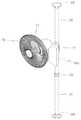
도 4는 본 발명에 따른 위치와 높이의 조절이 용이한 선풍기의 지지대와 선풍기의 결합부분의 단면도1 is a perspective view of an example of a fan in which the position and height can be easily adjusted according to the present invention
Figure 2 is a perspective view of an example of a state in which a fan for easy position and height adjustment according to the present invention is installed in the front of an air conditioner
3 is a perspective view of a state in which an electric fan for easy position and height adjustment according to the present invention is installed on a window frame
Figure 4 is a cross-sectional view of a support base of the fan with easy adjustment of the position and height according to the present invention and the coupling portion of the fan
본 발명은 다양한 변경을 가할 수 있고 여러 가지 실시예를 가질 수 있는 바, 특정 실시예들을 도면에 예시하고, 상세한 설명을 통해 설명하고자 한다. 그러나 이는 본 발명을 특정한 실시 형태에 대해 한정하려는 것이 아니며, 본 발명의 사상 및 기술 범위에 포함되는 모든 변경, 균등물 내지 대체물을 포함하는 것으로 이해되어야 한다.In the present invention, various changes may be made and various embodiments may be provided, and specific embodiments are illustrated in the drawings, and will be described through detailed description. However, this is not intended to limit the present invention to a specific embodiment, it is to be understood to include all changes, equivalents, or substitutes included in the spirit and scope of the present invention.
각 도면을 설명하면서 유사한 참조부호를 유사한 구성요소에 대해 사용하였다. 본 발명을 설명함에 있어서 관련된 공지 기술에 대한 구체적인 설명이 본 발명의 요지를 흐릴 수 있다고 판단되는 경우 그 상세한 설명을 생략한다.In describing each drawing, similar reference numerals have been used for similar elements. In describing the present invention, when it is determined that a detailed description of a related known technology may obscure the subject matter of the present invention, a detailed description thereof will be omitted.
본 발명은 높이 조절이 자유로워 사용자가 원하는 높이에서 작동시킬 수 있음에 따라 더운 공기를 효율적으로 배출시킬 수 있다.According to the present invention, since the height adjustment is free, the user can operate at a desired height, thereby efficiently discharging hot air.
이러한 본 발명의 위치와 높이의 조절이 용이한 선풍기는 구동수단의 구동에 의해 회전하는 날개를 구비한 선풍기(10)에 있어서, 상기 선풍기는 하기 지지대를 따라 승강되어 높이를 조절한 상태로 지지대에 고정되는 승강고정구(12)를 더 구비하고, 상기 승강고정구에 형성된 관통홀(12h)을 관통하여 설치되고, 하단은 바닥에 지지되고 상단은 천장에 지지되어 천장과 바닥 사이에 고정되는 지지대(20)를 구비하여, 상기 지지대(2)를 원하는 위치에 고정하여 선풍기의 위치를 조절하고, 지지대에 고정된 승강고정구의 높이를 조절함에 따라 선풍기의 높이 및 위치 조절이 자유롭게 이루어질 수 있게 한 것을 특징으로 한다.The position and height of the electric fan of the present invention is easily adjusted in a
상기 선풍기(10)는 바람을 발생시키는 수단으로 통상의 선풍기 또는 세큐레이터 등과 같이 구동수단의 구동에 의해 회전하는 송풍날개를 구비하고 있으며, 일측에는 바람의 세기, 방향 등을 제어하기 위한 조작패널(10c)이 일체로 설치되어 있다.The
이러한 선풍기는 통상의 것과 동일 유사한 것으로 이에 대한 상세한 설명은 생략한다.Such a fan is the same as that of a conventional fan, and a detailed description thereof will be omitted.
다만, 본 발명의 선풍기는 지지대와 결합하여 높이를 조절할 수 있게 하기 위해 일측에 상기한 승강고정구(12)를 구비하고 있다.However, the fan of the present invention is provided with the above-described
상기 승강고정구(12)는 다양하게 변형하여 실시 할 수 있으나, 구조가 단순한 것을 일예로 설명하면, 지지대(20)의 외주면에 밀착되는 관통홀(12)을 형성하되, 일부를 분리가능하게 구성하여 관통홀이 개방된 상태에서 지지대에 설치하고 나머지 반을 결합함에 의해 지지대로부터 분리되지 않게 구성할 수 있다.The
이러한 승강고정구(12)는 도 1 내지 도 4에 도시한 바와 같이 지지대(20)에 고정된다.This
상기 승강고정구(12)는 높이 조절이 가능하게 하는 것이 바람직하고, 이를 위해 형성된 관통홀(12h)은 아래는 넓고 위는 좁은 하광상협으로 이루어진다.It is preferable that the height of the
즉, 상기 관통홀(12h)은 상대적으로 아래쪽이 넓고 위쪽은 좁아 위로 가면 점차 넓어지는 경사면을 갖고 있다.That is, the through-
이렇게 하광상협의 관통홀(12h)의 내부에는 상기 지지대의 외주면에는 아래는 두껍고 위로 가면 점차 얇아지는 하후상박의 고정링(12r)을 더 설치하였다.In this way, a
이렇게 고정링을 설치하고, 고정링의 높이를 조절한 후, 상기 승강고정구를 고정링의 외주면에 설치하면 고정링에 형성된 하광상협의 관통홀(12h)이 고정링의 외주면을 밀어 고정링이 지지대의 외주면에 밀착된 상태가 되고 이 상태에서 승강고정구가 아래로 향하는 힘을 받으면 고정의 두꺼운 부분이 관통홀에 결려 승강고정구가 더 이상 아래로 이동할 수 없어 승강고정구가 지지대의 소정 위치에 고정되고, 승강고정구가 일체로 설치된 선풍기의 높이가 조절되는 것이다.After installing the retaining ring and adjusting the height of the retaining ring, when the lifting fixture is installed on the outer circumferential surface of the retaining ring, the through-
또한, 상기 지지대(20)는 길이 조절이 가능한 것이 바람직하다.In addition, it is preferable that the
즉, 본 발명의 선풍기는 천정과 바닥 사이에 고정된 지지대에 의해 소정 높이에 고정되고, 이러한 지지대를 천장과 바닥 사이에 고정하되, 원할 때 쉽게 해체할 수 있게 하는 것이 바람직하고, 선풍기가 설치되는 천장과 지붕 사이의 간격은 건물의 구조에 따라 다양함에 따라 지지대의 길이가 조절되는 것이 바람직하다.That is, the fan of the present invention is fixed to a predetermined height by a support fixed between the ceiling and the floor, and the support is fixed between the ceiling and the floor, but it is preferable that the fan can be easily disassembled when desired, and the fan is installed. It is preferable that the length of the support is adjusted as the distance between the ceiling and the roof varies according to the structure of the building.
이에 상기 지지대(20)는 상부지지대(21)와 하부지지대(22)로 이루어지고, 이들을 서로 신축가능하게 텔레스코픽하게 결합되어 있으며, 두 지지대 중 일측 지지대의 단부에는 높이조절구(23)가 설치되어 어느 일측의 지지대가 다른 지지대로 끼워지는 길이를 조절함에 의해 지지대 전체의 길이가 조절되게 하였다.Accordingly, the
즉, 일예로 하부지지대의 내경이 상부지지대의 외경과 같거나 작게 형성하고, 상부지지대의 하단을 하부지지대의 상단에 끼워 결합한 후, 상기 높이조절구(23)를 조이면 상부지지대가 하부지지대의 일단에 고정되어 두 지지대가 서로 분리되거나 짧아지는 것이 방지되는 것이다.That is, as an example, the inner diameter of the lower support is formed equal to or smaller than the outer diameter of the upper support, the lower end of the upper support is fitted to the upper end of the lower support, and then, when the
상기와 같이 구성된 지지대(20)의 양단에는 각각 받침판(24)를 더 설치하여 바닥이나 천장을 보호할 수 있게 하였다.Supporting
상기 지지대는 가볍고 취급을 용이하게 할 수 있도록 원통형 파이프로 만드는 것이 바람직하고, 이렇게 만들어진 지지대의 양단은 바닥과 천장에 접촉된 상태가 된다.The support is preferably made of a cylindrical pipe in order to be light and easy to handle, and both ends of the support made in this way are in contact with the floor and the ceiling.
이러한 지지대를 설치할 때 지지대의 양단에 접촉된 바닥이나 천장이 파이프에 의해 손상될 수 있고 이를 방지하기 위해 상기한 받침판(24)을 더 설치하여 바닥과 천장에 접촉되는 면적을 넓힌 것이다.When installing such a support, the floor or ceiling in contact with both ends of the support may be damaged by a pipe, and in order to prevent this, the
이렇게 받침판을 더 설치함에 의해 지지대가 천장과 바닥에 보다 견고하게 지지될 수 있는 효과도 있다.There is also an effect that the support can be more firmly supported on the ceiling and the floor by further installing the support plate.
상기와 같이 구성된 본 발명의 선풍기는 도 2 및 도 3에 도시한 바와 같이 에어컨의 정면 또는 창틀 등에 설치될 수 있으며, 이에 따라 에어컨의 공기를 보다 고르게 순환시킬 수 있을 뿐만 아니라, 창문 혹은 창틀에 안전하게 설치함으로써 강제 대류(공기 순환)로 내부의 뜨거운 공기를 방출하고, 외부의 차가운 공기를 들어오게 할 수 있는 것이다.The fan of the present invention configured as described above may be installed in the front of the air conditioner or the window frame, as shown in FIGS. 2 and 3, and thus it is possible to circulate the air of the air conditioner more evenly and safely to the window or window frame. By installing it, it is possible to release hot air inside by forced convection (air circulation) and to let outside cold air in.
10: 선풍기10c: 조작패널
11: 본체12: 승강고정구
12r: 고정링
20: 지지대
21: 하부지지봉22: 상부지지봉
23: 높이조절구24: 받침판10:
11: main body 12: lifting fixture
12r: retaining ring
20: support
21: lower support rod 22: upper support rod
23: height adjuster 24: base plate
Claims (3)
Translated fromKorean상기 선풍기(10)의 일측은 승강고정구(12)를 구비하여 지지대(20)를 따라 승강되어 고정링(12r)으로 지지대(20)에 고정되게 하며,
상기 지지대(20)의 양단은 받침판(24)이 각각 설치되어 하단은 바닥에 지지되고 상단은 천장에 지지되어 천장과 바닥 사이에 고정되게 하되 상기 지지대(20)는 상부지지대(21)와 하부지지대(22)로 이루어져서 신축가능하게 결합되고, 높이조절구(23)로 지지대(20) 전체의 길이가 조절되게 한 구성으로 상기 지지대(20)를 원하는 위치에 고정하여 선풍기(10)의 위치를 조절할 수 있도록 하며,
상기 승강고정구(12)는 관통홀(12h)이 형성되어 지지대(20)에 관통 설치하되 상기 관통홀(12h)의 아래쪽은 넓고 위는 위쪽은 점차 좁아지는 하광상협의 경사면으로 이루어지고, 상기 승강고정구(12)의 관통홀(12h)에 아래는 두껍고 위로 가면서 점차 얇아지는 하후상박의 고정링(12r)을 밀착시켜 승강고정구(12)가 지지대(20)의 소정 위치에 고정되게 한 구성으로 상기 지지대(20)에 고정되는 승강고정구(12)의 높이를 조절하여 선풍기(10)의 높이 및 위치 조절이 자유롭게 이루어질 수 있도록 한 것을 특징으로 하는 위치와 높이의 조절이 용이한 선풍기.
An electric fan 10 having blades that rotate by driving the driving means,
One side of the fan 10 is provided with a lifting fixture 12 so as to be raised and lowered along the support 20 to be fixed to the support 20 with a fixing ring 12r,
Supporting plates 24 are installed at both ends of the support 20 so that the lower end is supported on the floor and the upper end is supported on the ceiling to be fixed between the ceiling and the floor, but the support 20 includes an upper support 21 and a lower support. It is composed of (22), it is combined to be elastic, and the length of the support (20) is adjusted with a height adjustment device (23), and the position of the fan (10) can be adjusted by fixing the support (20) at a desired position. And
The lifting fixture 12 is provided with a through hole 12h to penetrate through the support 20, but the lower part of the through hole 12h is wide and the upper part is made of an inclined surface of the lower gwangsanghyup gradually narrowing, and the lifting The structure in which the lifting fixture 12 is fixed at a predetermined position of the support 20 by in close contact with the fixing ring 12r of the lower and lower upper foil, which is thicker at the bottom and gradually becomes thinner as it goes upward, to the through hole 12h of the fixture 12. A fan with easy position and height adjustment, characterized in that the height and position of the fan 10 can be freely adjusted by adjusting the height of the lifting fixture 12 fixed to the support 20.
Priority Applications (1)
| Application Number | Priority Date | Filing Date | Title |
|---|---|---|---|
| KR1020180128167AKR102171147B1 (en) | 2018-10-25 | 2018-10-25 | electric fan with position control |
Applications Claiming Priority (1)
| Application Number | Priority Date | Filing Date | Title |
|---|---|---|---|
| KR1020180128167AKR102171147B1 (en) | 2018-10-25 | 2018-10-25 | electric fan with position control |
Publications (2)
| Publication Number | Publication Date |
|---|---|
| KR20200046675A KR20200046675A (en) | 2020-05-07 |
| KR102171147B1true KR102171147B1 (en) | 2020-10-28 |
Family
ID=70733527
Family Applications (1)
| Application Number | Title | Priority Date | Filing Date |
|---|---|---|---|
| KR1020180128167AActiveKR102171147B1 (en) | 2018-10-25 | 2018-10-25 | electric fan with position control |
Country Status (1)
| Country | Link |
|---|---|
| KR (1) | KR102171147B1 (en) |
Families Citing this family (2)
| Publication number | Priority date | Publication date | Assignee | Title |
|---|---|---|---|---|
| CN220748589U (en)* | 2023-09-06 | 2024-04-09 | 宋振明 | Lifting tower fan |
| CN118462658B (en)* | 2024-05-24 | 2025-01-28 | 上海沃克通用设备有限公司 | A mixed flow fan |
Citations (1)
| Publication number | Priority date | Publication date | Assignee | Title |
|---|---|---|---|---|
| KR200386794Y1 (en)* | 2005-03-11 | 2005-06-16 | 이승주 | A Height adjustable coat hanger |
Family Cites Families (5)
| Publication number | Priority date | Publication date | Assignee | Title |
|---|---|---|---|---|
| US5558501A (en)* | 1995-03-03 | 1996-09-24 | Duracraft Corporation | Portable ceiling fan |
| JP3074717U (en)* | 2000-07-10 | 2001-01-26 | エレクター株式会社 | Assembly shelf |
| KR100917670B1 (en) | 2008-02-15 | 2009-09-16 | 윤근수 | Hot and cold fan |
| GB2468317A (en) | 2009-03-04 | 2010-09-08 | Dyson Technology Ltd | Height adjustable and oscillating fan |
| KR101263832B1 (en) | 2011-06-22 | 2013-05-16 | 홍은수 | Multi-functional electric fan |
- 2018
- 2018-10-25KRKR1020180128167Apatent/KR102171147B1/enactiveActive
Patent Citations (1)
| Publication number | Priority date | Publication date | Assignee | Title |
|---|---|---|---|---|
| KR200386794Y1 (en)* | 2005-03-11 | 2005-06-16 | 이승주 | A Height adjustable coat hanger |
Also Published As
| Publication number | Publication date |
|---|---|
| KR20200046675A (en) | 2020-05-07 |
Similar Documents
| Publication | Publication Date | Title |
|---|---|---|
| USRE49868E1 (en) | Medallion fan | |
| US20080069698A1 (en) | Reversible fan blade for a ceiling-suspended fan | |
| EP2846045A1 (en) | Fan | |
| KR101833413B1 (en) | Ceiling type air conditioner | |
| KR102171147B1 (en) | electric fan with position control | |
| KR102610037B1 (en) | Ceiling type air conditioner | |
| JP2014005787A (en) | Blower | |
| KR20130138920A (en) | The dual-structured hidden blade fan or blower including air vents | |
| US20120318179A1 (en) | Table and fan combo | |
| CN105352155B (en) | Air conditioner air supply structure, air conditioner and control method thereof | |
| CN105637225B (en) | Ventilation equipment | |
| CN102016435A (en) | energy efficient buildings | |
| KR200433894Y1 (en) | Tilting Rotary Fan Structure | |
| CN209557292U (en) | Omnidirectional's fan | |
| KR20110107512A (en) | Floor Diffuser | |
| KR101088344B1 (en) | Dustproof air conditioner | |
| JP2015140971A (en) | Ceiling embedded type indoor equipment of air conditioner | |
| TWM538084U (en) | Solar fan | |
| CN108679814A (en) | Air conditioner indoor unit and its outlet air method of adjustment | |
| CN109668318B (en) | Electric heating film heater with protection structure and capable of radiating heat in multiple directions | |
| KR200485674Y1 (en) | A fan | |
| JPH10300181A (en) | Diffuser | |
| CN114322531B (en) | Accelerated drying device applied to house construction | |
| JP6469274B1 (en) | Blower | |
| JP7236536B2 (en) | Air conditioner indoor unit |
Legal Events
| Date | Code | Title | Description |
|---|---|---|---|
| PA0109 | Patent application | St.27 status event code:A-0-1-A10-A12-nap-PA0109 | |
| PA0201 | Request for examination | St.27 status event code:A-1-2-D10-D11-exm-PA0201 | |
| D13-X000 | Search requested | St.27 status event code:A-1-2-D10-D13-srh-X000 | |
| D14-X000 | Search report completed | St.27 status event code:A-1-2-D10-D14-srh-X000 | |
| PE0902 | Notice of grounds for rejection | St.27 status event code:A-1-2-D10-D21-exm-PE0902 | |
| E13-X000 | Pre-grant limitation requested | St.27 status event code:A-2-3-E10-E13-lim-X000 | |
| P11-X000 | Amendment of application requested | St.27 status event code:A-2-2-P10-P11-nap-X000 | |
| P13-X000 | Application amended | St.27 status event code:A-2-2-P10-P13-nap-X000 | |
| PG1501 | Laying open of application | St.27 status event code:A-1-1-Q10-Q12-nap-PG1501 | |
| E902 | Notification of reason for refusal | ||
| PE0902 | Notice of grounds for rejection | St.27 status event code:A-1-2-D10-D21-exm-PE0902 | |
| P11-X000 | Amendment of application requested | St.27 status event code:A-2-2-P10-P11-nap-X000 | |
| P13-X000 | Application amended | St.27 status event code:A-2-2-P10-P13-nap-X000 | |
| E701 | Decision to grant or registration of patent right | ||
| PE0701 | Decision of registration | St.27 status event code:A-1-2-D10-D22-exm-PE0701 | |
| GRNT | Written decision to grant | ||
| PR0701 | Registration of establishment | St.27 status event code:A-2-4-F10-F11-exm-PR0701 | |
| PR1002 | Payment of registration fee | St.27 status event code:A-2-2-U10-U11-oth-PR1002 Fee payment year number:1 | |
| PG1601 | Publication of registration | St.27 status event code:A-4-4-Q10-Q13-nap-PG1601 | |
| R18-X000 | Changes to party contact information recorded | St.27 status event code:A-5-5-R10-R18-oth-X000 | |
| PR1001 | Payment of annual fee | St.27 status event code:A-4-4-U10-U11-oth-PR1001 Fee payment year number:4 | |
| PR1001 | Payment of annual fee | St.27 status event code:A-4-4-U10-U11-oth-PR1001 Fee payment year number:5 | |
| PR1001 | Payment of annual fee | St.27 status event code:A-4-4-U10-U11-oth-PR1001 Fee payment year number:6 |