KR102170767B1 - Needle-free syringe with piston driven by high-frequency vibration - Google Patents
Needle-free syringe with piston driven by high-frequency vibrationDownload PDFInfo
- Publication number
- KR102170767B1 KR102170767B1KR1020180051026AKR20180051026AKR102170767B1KR 102170767 B1KR102170767 B1KR 102170767B1KR 1020180051026 AKR1020180051026 AKR 1020180051026AKR 20180051026 AKR20180051026 AKR 20180051026AKR 102170767 B1KR102170767 B1KR 102170767B1
- Authority
- KR
- South Korea
- Prior art keywords
- space
- injection device
- piston
- volatile liquid
- drug
- Prior art date
- Legal status (The legal status is an assumption and is not a legal conclusion. Google has not performed a legal analysis and makes no representation as to the accuracy of the status listed.)
- Active
Links
Images


Classifications
- A—HUMAN NECESSITIES
- A61—MEDICAL OR VETERINARY SCIENCE; HYGIENE
- A61M—DEVICES FOR INTRODUCING MEDIA INTO, OR ONTO, THE BODY; DEVICES FOR TRANSDUCING BODY MEDIA OR FOR TAKING MEDIA FROM THE BODY; DEVICES FOR PRODUCING OR ENDING SLEEP OR STUPOR
- A61M5/00—Devices for bringing media into the body in a subcutaneous, intra-vascular or intramuscular way; Accessories therefor, e.g. filling or cleaning devices, arm-rests
- A61M5/178—Syringes
- A61M5/30—Syringes for injection by jet action, without needle, e.g. for use with replaceable ampoules or carpules
- A61M5/3007—Syringes for injection by jet action, without needle, e.g. for use with replaceable ampoules or carpules with specially designed jet passages at the injector's distal end
- A—HUMAN NECESSITIES
- A61—MEDICAL OR VETERINARY SCIENCE; HYGIENE
- A61M—DEVICES FOR INTRODUCING MEDIA INTO, OR ONTO, THE BODY; DEVICES FOR TRANSDUCING BODY MEDIA OR FOR TAKING MEDIA FROM THE BODY; DEVICES FOR PRODUCING OR ENDING SLEEP OR STUPOR
- A61M5/00—Devices for bringing media into the body in a subcutaneous, intra-vascular or intramuscular way; Accessories therefor, e.g. filling or cleaning devices, arm-rests
- A61M5/178—Syringes
- A61M5/20—Automatic syringes, e.g. with automatically actuated piston rod, with automatic needle injection, filling automatically
- A61M5/2046—Media being expelled from injector by gas generation, e.g. explosive charge
- A—HUMAN NECESSITIES
- A61—MEDICAL OR VETERINARY SCIENCE; HYGIENE
- A61M—DEVICES FOR INTRODUCING MEDIA INTO, OR ONTO, THE BODY; DEVICES FOR TRANSDUCING BODY MEDIA OR FOR TAKING MEDIA FROM THE BODY; DEVICES FOR PRODUCING OR ENDING SLEEP OR STUPOR
- A61M5/00—Devices for bringing media into the body in a subcutaneous, intra-vascular or intramuscular way; Accessories therefor, e.g. filling or cleaning devices, arm-rests
- A61M5/178—Syringes
- A61M5/31—Details
- A61M5/315—Pistons; Piston-rods; Guiding, blocking or restricting the movement of the rod or piston; Appliances on the rod for facilitating dosing ; Dosing mechanisms
- A61M5/31565—Administration mechanisms, i.e. constructional features, modes of administering a dose
- A61M5/31566—Means improving security or handling thereof
- A—HUMAN NECESSITIES
- A61—MEDICAL OR VETERINARY SCIENCE; HYGIENE
- A61M—DEVICES FOR INTRODUCING MEDIA INTO, OR ONTO, THE BODY; DEVICES FOR TRANSDUCING BODY MEDIA OR FOR TAKING MEDIA FROM THE BODY; DEVICES FOR PRODUCING OR ENDING SLEEP OR STUPOR
- A61M5/00—Devices for bringing media into the body in a subcutaneous, intra-vascular or intramuscular way; Accessories therefor, e.g. filling or cleaning devices, arm-rests
- A61M5/178—Syringes
- A61M5/31—Details
- A61M5/315—Pistons; Piston-rods; Guiding, blocking or restricting the movement of the rod or piston; Appliances on the rod for facilitating dosing ; Dosing mechanisms
- A61M5/31565—Administration mechanisms, i.e. constructional features, modes of administering a dose
- A61M5/31576—Constructional features or modes of drive mechanisms for piston rods
- A—HUMAN NECESSITIES
- A61—MEDICAL OR VETERINARY SCIENCE; HYGIENE
- A61M—DEVICES FOR INTRODUCING MEDIA INTO, OR ONTO, THE BODY; DEVICES FOR TRANSDUCING BODY MEDIA OR FOR TAKING MEDIA FROM THE BODY; DEVICES FOR PRODUCING OR ENDING SLEEP OR STUPOR
- A61M5/00—Devices for bringing media into the body in a subcutaneous, intra-vascular or intramuscular way; Accessories therefor, e.g. filling or cleaning devices, arm-rests
- A61M5/178—Syringes
- A61M5/31—Details
- A61M2005/3128—Incorporating one-way valves, e.g. pressure-relief or non-return valves
- A—HUMAN NECESSITIES
- A61—MEDICAL OR VETERINARY SCIENCE; HYGIENE
- A61M—DEVICES FOR INTRODUCING MEDIA INTO, OR ONTO, THE BODY; DEVICES FOR TRANSDUCING BODY MEDIA OR FOR TAKING MEDIA FROM THE BODY; DEVICES FOR PRODUCING OR ENDING SLEEP OR STUPOR
- A61M2205/00—General characteristics of the apparatus
- A61M2205/33—Controlling, regulating or measuring
- A61M2205/3331—Pressure; Flow
- A—HUMAN NECESSITIES
- A61—MEDICAL OR VETERINARY SCIENCE; HYGIENE
- A61M—DEVICES FOR INTRODUCING MEDIA INTO, OR ONTO, THE BODY; DEVICES FOR TRANSDUCING BODY MEDIA OR FOR TAKING MEDIA FROM THE BODY; DEVICES FOR PRODUCING OR ENDING SLEEP OR STUPOR
- A61M2205/00—General characteristics of the apparatus
- A61M2205/82—Internal energy supply devices
- A61M2205/8218—Gas operated
Landscapes
- Health & Medical Sciences (AREA)
- Vascular Medicine (AREA)
- Engineering & Computer Science (AREA)
- Anesthesiology (AREA)
- Biomedical Technology (AREA)
- Heart & Thoracic Surgery (AREA)
- Hematology (AREA)
- Life Sciences & Earth Sciences (AREA)
- Animal Behavior & Ethology (AREA)
- General Health & Medical Sciences (AREA)
- Public Health (AREA)
- Veterinary Medicine (AREA)
- Infusion, Injection, And Reservoir Apparatuses (AREA)
Abstract
Translated fromKoreanDescription
Translated fromKorean본 발명은 무침 주사 장치에 관한 것으로, 보다 상세하게는 약물 분사를 위해 피스톤을 구동하는 신규한 방식의 무침 주사 장치에 관한 발명이다.The present invention relates to a needleless injection device, and more particularly, to a novel method of driving a piston for drug injection.
종래부터 사람이나 동물의 생체 내에 약물을 주입하는 무침(needle-free) 주사 장치가 사용되고 있다. 무침 주사 장치는 바늘(needle)이 없기 때문에 주사 장치의 분사 노즐에서 약물이 짧은 시간에 높은 압력으로 분사되어 생체 내로 주입되어야 하고, 이를 위해 주사 장치 내의 피스톤을 움직여서 약물을 분사한다.Conventionally, a needle-free injection device for injecting drugs into a human or animal body has been used. Since the needleless injection device does not have a needle, the drug must be injected into the living body by spraying the drug from the injection nozzle of the injection device at a high pressure in a short time, and for this purpose, the drug is injected by moving a piston in the injection device.
종래 무침 주사 장치는 피스톤을 움직이기 위해 예컨대 압전소자, 화약 폭발, 고압 가스 등을 사용한다. 화약 폭발 방식의 경우 한번 사용된 화약을 버리고 화약을 다시 공급해주어야 하며 고압 가스 방식의 경우에도 한번 사용된 가스를 배출하고 새로운 고압 가스를 공급받아야 하는 문제가 있다.Conventional needleless injection devices use, for example, piezoelectric elements, explosives, and high-pressure gas to move a piston. In the case of the explosive explosive method, there is a problem in that the used explosive is discarded and the explosive is supplied again, and in the case of the high pressure gas method, the used gas must be discharged and a new high pressure gas must be supplied.
따라서 이러한 기존 방식의 문제를 해결한 신규한 방식으로 피스톤을 움직여 약물을 분사하는 무침 주사 장치의 필요성이 제기된다.Therefore, the necessity of a needleless injection device for injecting drugs by moving a piston in a novel method that solves the problem of this conventional method is raised.
본 발명의 일 실시예에 따르면, 휘발성 액체를 진동에 의해 기화하여 부피를 팽창시키고 이 팽창된 휘발성 액체의 압력으로 피스톤을 움직여 약물을 분사할 수 있는 무침 주사 장치를 제공하는 것을 목적으로 한다.According to an embodiment of the present invention, an object of the present invention is to provide a needleless injection device capable of injecting a drug by vaporizing a volatile liquid by vibration to expand its volume and by moving a piston under the pressure of the expanded volatile liquid.
본 발명의 일 실시예에 따르면, 생체 내에 주입할 약물의 주입량을 조절할 수 있는 구조를 갖는 무침 주사 장치를 제공하는 것을 목적으로 한다.According to an embodiment of the present invention, an object of the present invention is to provide a needleless injection device having a structure capable of controlling an injection amount of a drug to be injected into a living body.
본 발명의 일 실시예에 따르면, 약물을 주입하는 무침 주사 장치로서, 길이방향을 따라 제1 공간과 제2 공간을 갖는 통형상의 주사장치 본체부; 상기 주사장치 본체부의 제2 공간측의 단부에 형성된 노즐; 상기 제1 공간과 제2 공간 사이에 배치되며 상기 주사장치 본체부의 길이 방향을 따라 이동가능한 피스톤; 및 상기 제1 공간에 수용된 휘발성 액체에 고주파 진동을 인가하는 진동 생성부;를 포함하고, 상기 진동 생성부의 고주파 진동에 의해 상기 휘발성 액체의 부피를 팽창시켜 상기 피스톤을 가압함으로써, 상기 제2 공간에 수용된 약물을 상기 노즐을 통해 분사하도록 구성된 무침 주사 장치를 개시한다.According to an embodiment of the present invention, there is provided a needleless injection device for injecting a drug, comprising: a cylindrical injection device main body having a first space and a second space along a longitudinal direction; A nozzle formed at an end of the main body of the injection device on the second space side; A piston disposed between the first space and the second space and movable along the longitudinal direction of the main body of the injection device; And a vibration generating unit for applying high-frequency vibration to the volatile liquid accommodated in the first space, wherein the volume of the volatile liquid is expanded by high-frequency vibration of the vibration generating unit to press the piston, thereby causing the second space Disclosed is a needleless injection device configured to inject a contained drug through the nozzle.
본 발명의 일 실시예에 따르면, 상기 무침 주사 장치가 휘발성 액체를 공급하고 배출하는 휘발성 액체 공급/배출 시스템을 더 포함할 수 있고, 이 때 상기 휘발성 액체 공급/배출 시스템은 상기 휘발성 액체를 수용하는 제1 탱크; 상기 제1 공간으로부터 배출되는 휘발성 액체를 수용하는 제2 탱크; 상기 제1 공간과 상기 제1 탱크 사이의 제1 경로 및 상기 제1 공간과 상기 제2 탱크 사이의 제2 경로를 개폐하는 적어도 하나의 밸브; 및 상기 밸브의 개폐를 제어하는 제1 제어부;를 더 포함할 수 있다.According to an embodiment of the present invention, the needleless injection device may further include a volatile liquid supply/discharge system for supplying and discharging a volatile liquid, wherein the volatile liquid supply/discharge system includes the volatile liquid. First tank; A second tank for receiving the volatile liquid discharged from the first space; At least one valve for opening and closing a first path between the first space and the first tank and a second path between the first space and the second tank; And a first control unit for controlling the opening and closing of the valve.
또한 본 발명의 일 실시예에 따르면, 상기 무침 주사 장치가, 상기 주사장치 본체부의 내측 표면에 설치되고 상기 주사장치 본체부의 중심축을 향해 돌출되어 상기 피스톤의 이동을 제한하는 스토퍼; 상기 스토퍼와 연결되고 상기 스토퍼를 상기 주사장치 본체부의 내측 표면 안쪽으로 이동시키도록 동작하는 구동부; 및 상기 구동부의 동작을 제어하는 제2 제어부;를 더 포함할 수 있다. According to an embodiment of the present invention, the needleless injection device includes: a stopper installed on an inner surface of the injection device main body and protruding toward a central axis of the injection device main body to restrict movement of the piston; A driving unit connected to the stopper and operative to move the stopper inside the inner surface of the main body of the injection device; And a second control unit for controlling the operation of the driving unit.
또한 본 발명의 일 실시예에 따르면, 상기 주사장치 본체부가, 내부에 상기 피스톤의 이동 경로와 상기 제2 공간을 갖는 하부 하우징; 내부에 상기 제1 공간을 갖는 상부 하우징; 및 상기 하부 하우징과 하부 하우징을 연결하는 조절너트;를 포함하고, 이 때 상기 조절너트가 상기 하부 하우징의 상단의 적어도 일부 외주면과 상기 상부 하우징의 하단의 적어도 일부 외주면을 둘러싸도록 형성되되, 상기 하부 하우징 또는 상부 하우징 중 적어도 하나와의 결합 길이가 조절되도록 구성되고, 상기 결합 길이의 조절에 의해 상기 제2 공간의 부피가 증감하도록 구성될 수 있다.In addition, according to an embodiment of the present invention, the main body of the injection device includes: a lower housing having a movement path of the piston and the second space therein; An upper housing having the first space therein; And an adjustment nut connecting the lower housing and the lower housing, wherein the adjustment nut is formed to surround at least a partial outer circumferential surface of the upper end of the lower housing and at least a partial outer circumferential surface of the lower end of the upper housing, wherein the lower The coupling length with at least one of the housing or the upper housing may be adjusted, and the volume of the second space may be increased or decreased by adjusting the coupling length.
본 발명의 일 실시예에 따르면, 휘발성 액체를 고주파 진동에 의해 기화하여 부피를 팽창시키고 이 팽창된 휘발성 액체의 압력으로 피스톤을 움직여 약물을 분사할 수 있는 신규한 방식의 무침 주사 장치를 제공할 수 있다.According to an embodiment of the present invention, it is possible to provide a novel method of needleless injection device capable of injecting drugs by vaporizing a volatile liquid by high-frequency vibration to expand the volume and by moving a piston under the pressure of the expanded volatile liquid. have.
본 발명의 일 실시예에 따르면, 한번 사용된 기화된 휘발성 액체가 다시 액화한 후 재사용할 수 있으므로 휘발성 액체를 낭비하지 않고 계속 사용할 수 있는 이점이 있고, 또한 휘발성 액체 공급/배출 시스템을 구비한 경우 기화된 휘발성 액체가 다시 액화할 때까지 기다릴 필요가 없으므로 약물 분사 동작을 연속적으로 수행할 수 있는 이점이 있다.According to an embodiment of the present invention, since the vaporized volatile liquid once used can be reused after being liquefied again, there is an advantage that the volatile liquid can be continuously used without wasting, and a volatile liquid supply/discharge system is provided. Since there is no need to wait for the vaporized volatile liquid to liquefy again, there is an advantage that the drug injection operation can be continuously performed.
또한 본 발명의 일 실시예에 따른 스토퍼를 구비한 무침 주사 장치의 경우 휘발성 액체가 팽창하여 충분한 압력으로 피스톤을 가압할 때까지 기다렸다가 충분한 압력이 되었을 때 피스톤을 동작시킬 수 있으므로 높은 분사압력으로 약물을 생체 내로 주입할 수 있고 약물 분사 시점을 사용자가 조절할 수도 있는 이점이 있다.In addition, in the case of the needleless injection device having a stopper according to an embodiment of the present invention, since the volatile liquid expands and the piston is pressed with sufficient pressure, the piston can be operated when the pressure becomes sufficient. There is an advantage that it can be injected into a living body and the user can control the timing of drug injection.
또한 본 발명의 일 실시예에 따르면 주사장치 본체부를 구성하는 상부 하우징과 하부 하우징을 조절너트로 결합하여 상부 하우징과 하부 하우징 사이의 간격을 조절할 수 있도록 구성함으로써 필요에 따라 약물의 주입량을 편리하게 조절할 수 있는 이점을 가진다.In addition, according to an embodiment of the present invention, by combining the upper housing and the lower housing constituting the main body of the injection device with an adjustment nut to adjust the distance between the upper and lower housings, the injection amount of the drug can be conveniently adjusted as needed. Has the advantage of being able to.
도1은 본 발명의 제1 실시예에 따른 무침 주사 장치를 설명하기 위한 도면,
도2는 본 발명의 제2 실시예에 따른 무침 주사 장치를 설명하기 위한 도면,
도3은 본 발명의 제3 실시예에 따른 무침 주사 장치를 설명하기 위한 도면,
도4 내지 도6은 본 발명의 제4 실시예에 따른 무침 주사 장치를 설명하기 위한 도면,
도7은 본 발명의 제5 실시예에 따른 무침 주사 장치를 설명하기 위한 도면이다.1 is a view for explaining a needleless injection device according to a first embodiment of the present invention;
2 is a view for explaining a needleless injection device according to a second embodiment of the present invention;
3 is a view for explaining a needleless injection device according to a third embodiment of the present invention;
4 to 6 are views for explaining a needleless injection device according to a fourth embodiment of the present invention;
7 is a view for explaining a needleless injection device according to a fifth embodiment of the present invention.
이상의 본 발명의 목적들, 다른 목적들, 특징들 및 이점들은 첨부된 도면과 관련된 이하의 바람직한 실시예들을 통해서 쉽게 이해될 것이다. 그러나 본 발명은 여기서 설명되는 실시예들에 한정되지 않고 다른 형태로 구체화될 수도 있다. 오히려, 여기서 소개되는 실시예들은 개시된 내용이 철저하고 완전해질 수 있도록 그리고 당업자에게 본 발명의 사상이 충분히 전달될 수 있도록 하기 위해 제공되는 것이다.The above objects, other objects, features, and advantages of the present invention will be easily understood through the following preferred embodiments related to the accompanying drawings. However, the present invention is not limited to the embodiments described herein and may be embodied in other forms. Rather, the embodiments introduced herein are provided so that the disclosed content may be thorough and complete, and the spirit of the present invention may be sufficiently conveyed to those skilled in the art.
본 명세서에서, 어떤 구성요소가 다른 구성요소 상에 있다고 언급되는 경우에 그것은 다른 구성요소 상에 직접 형성될 수 있거나 또는 그들 사이에 제 3의 구성요소가 개재될 수도 있다는 것을 의미한다. 또한, 도면들에 있어서, 구성요소들의 두께는 기술적 내용의 효과적인 설명을 위해 과장된 것이다.In the present specification, when a component is referred to as being on another component, it means that it may be formed directly on the other component or that a third component may be interposed between them. In addition, in the drawings, the thickness of the components is exaggerated for effective description of the technical content.
본 명세서에서 제1, 제2 등의 용어가 구성요소들을 기술하기 위해서 사용된 경우, 이들 구성요소들이 이 같은 용어들에 의해서 한정되어서는 안된다. 이들 용어들은 단지 어느 구성요소를 다른 구성요소와 구별시키기 위해서 사용되었을 뿐이다. 여기에 설명되고 예시되는 실시예들은 그것의 상보적인 실시예들도 포함한다.In the present specification, when terms such as first and second are used to describe components, these components should not be limited by these terms. These terms are only used to distinguish one component from another component. The embodiments described and illustrated herein also include complementary embodiments thereof.
본 명세서에서, 단수형은 문구에서 특별히 언급하지 않는 한 복수형도 포함한다. 명세서에서 사용되는 '포함한다(comprise)' 및/또는 '포함하는(comprising)'은 언급된 구성요소는 하나 이상의 다른 구성요소의 존재 또는 추가를 배제하지 않는다.In this specification, the singular form also includes the plural form unless specifically stated in the phrase. As used in the specification, "comprise" and/or "comprising" does not exclude the presence or addition of one or more other components.
이하 도면을 참조하여 본 발명을 상세히 설명하도록 한다. 아래의 특정 실시예들을 기술하는데 있어서 여러 가지의 특정적인 내용들은 발명을 더 구체적으로 설명하고 이해를 돕기 위해 작성되었다. 하지만 본 발명을 이해할 수 있을 정도로 이 분야의 지식을 갖고 있는 독자는 이러한 여러 가지의 특정적인 내용들이 없어도 사용될 수 있다는 것을 인지할 수 있다. 어떤 경우에는, 발명을 기술하는 데 있어서 흔히 알려졌으면서 발명과 크게 관련 없는 부분들은 본 발명을 설명하는 데 있어 혼돈을 막기 위해 기술하지 않음을 미리 언급해 둔다.Hereinafter, the present invention will be described in detail with reference to the drawings. In describing the specific embodiments below, a number of specific contents have been prepared to explain the invention in more detail and to aid understanding. However, readers who have knowledge in this field to the extent that they can understand the present invention can recognize that it can be used without these various specific contents. In some instances, it should be noted in advance that parts that are commonly known in describing the invention and are not significantly related to the invention are not described in order to avoid confusion in describing the invention.
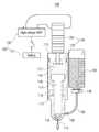
도1은 본 발명의 제1 실시예에 따른 무침 주사 장치(100)를 설명하기 위한 도면이다.1 is a view for explaining a
도면을 참조하면, 일 실시예에 따른 무침 주사 장치(100)는 주사장치 본체부(110), 진동 생성부(130), 및 약물 챔버(140)를 포함할 수 있다. 주사장치 본체부(110)는 내부에 빈 공간을 갖는 통형상의 부재이며, 상단부는 개방되어 있고 하단부에는 약물을 분사하기 위한 노즐(114)이 형성되어 있을 수 있다. 일 실시예에서 주사장치 본체부(110)는 원형의 단면을 가질 수 있지만, 대안적으로 삼각형, 사각형 등 다각형의 단면을 가질 수 있다.Referring to the drawings, the
일 실시예에서 주사장치 본체부(110)는 길이 방향을 따라 상부의 제1 공간(111)과 하부의 제2 공간(112)을 포함한다. 제1 공간(111)과 제2 공간(112) 사이에는 피스톤(120)이 배치되며, 피스톤(120)은 주사장치 본체부(110) 내부에 길이 방향(즉 도면에서 상하 방향)을 따라 형성된 이동 공간 내에서 길이 방향으로 움직일 수 있다.In an embodiment, the injection device
일 실시예에서 제1 공간(111)이 휘발성 액체로 채워질 수 있다. 본 명세서에서 "휘발성 액체"는 진동에 의해 쉽게 기화되는 액체를 의미한다. 일 실시예에서 휘발성 액체가 디에틸에테르, 이황화탄소, 아세트알데히드, 및 산화프로필렌 중 하나를 포함할 수 있다.In an embodiment, the
진동 생성부(130)가 결합부(113)를 통해 제1 공간(111)의 상부에 결합될 수 있다. 도시한 실시예에서 진동 생성부(130)는 제1 공간(111)에 수용된 휘발성 액체에 고주파 진동을 인가할 수 있다. 이 때 "고주파" 진동은 예를 들어 수 KHz 내지 수백 KHz 사이의 주파수를 갖는 진동일 수 있다.The vibration generating
일 실시예에서 진동 생성부(130)는 압전소자로 구현된다. 예를 들어 도시한 실시예에서 진동 생성부(130)는 다수의 압전소자를 적층하여 만든 압전스택(131)과 이 압전스택(131)에 연결되고 제1 공간(111) 내에 배치된 진동판(132)을 포함할 수 있다. 압전스택(131)은 배터리(151)와 고주파 전압 생성부(152) 등을 포함하는 전원부(150)에 연결되고, 전원부(150)로부터 고주파 전압을 인가받아 고주파 진동을 생성할 수 있다. 도시한 실시예에서 진동 생성부(130)가 압전스택으로 구현되었지만 대안적 실시예에서 압전스택 외의 공지의 다른 진동생성 방식으로 구현될 수도 있다.In one embodiment, the vibration generating
주사장치 본체부의 제1 공간(111)은 본체부(110)의 내측면, 결합부(113), 및 피스톤(120)의 상단부에 의해 둘러싸여 밀폐되어 있고, 이 제1 공간(111) 내부에 휘발성 액체가 충전되어 있다. 진동 생성부(130)에 의해 생성된 고주파 진동에 의해 휘발성 액체를 진동시키면 휘발성 액체의 적어도 일부가 버블화하여 기체가 되며 부피가 팽창하게 된다. 팽창된 휘발성 액체는 피스톤(120)을 가압하고, 이에 따라 피스톤(120)이 제2 공간(112)으로 움직이면서 제2 공간(112) 내에 수용되어 있는 약물을 분사노즐(114)을 통해 분사할 수 있다.The
일 실시예에서 주사장치 본체부(110) 내부에 피스톤(120)을 원래 위치로 복귀시키기 위한 탄성부재(117)를 더 포함할 수 있다. 도시한 실시예에서 탄성부재(117)는 코일 스프링으로 구현되었지만 대안적 실시예에서 다른 탄성 구조의 구성요소로 구현될 수도 있다. 탄성부재(117)는 제1 공간(111)과 제2 공간(112) 사이의 공간에 배치될 수 있다.In an embodiment, an
휘발성 액체의 팽창에 의해 휘발성 액체의 부피가 증가하여 피스톤(120)을 가압하면 피스톤(120)이 제2 공간(112)측으로 이동하며 약물을 분사하고, 그 후 피스톤(120)은 탄성부재(117)의 반발력을 지속적으로 받게 된다. 진동 생성부(130)에 의한 진동이 중단되면 제1 공간(111) 내에서 버블화로 인해 기화했던 휘발성 액체는 시간이 지남에 따라 다시 액화하여 부피가 줄어들며, 피스톤(120)은 휘발성 액체의 압력과 탄성부재(117)의 반발력이 균형을 이루는 지점까지 복귀할 수 있다.When the volume of the volatile liquid increases due to the expansion of the volatile liquid and presses the
이 때 일 실시예에서 피스톤(120)의 복귀시 과도한 상승을 방지하지 위해 스토퍼(118)를 더 포함할 수 있다. 도시한 일 실시예에서 스토퍼(118)는 주사장치 본체부(110)의 내부 표면에 돌출되어 형성되어 있고, 이에 따라 피스톤(120)의 상방향으로의 최대 상승 위치를 제한할 수 있다.In this case, in an embodiment, a
주사장치 본체부(110)의 측면부에는 공기 배출구(115)가 형성될 수 있다. 즉 피스톤(120)이 왕복 운동을 함에 따라 탄성부재(117)가 배치된 공간의 부피가 변하게 되는데, 피스톤(120)의 왕복 운동이 이 공간의 부피 변화에 의해 방해받지 않도록 하기 위해 공기 배출구(115)를 형성하였고, 이 공기 배출구(115)를 통해 외부의 공기가 탄성부재(117)가 배치된 공간으로 자유롭게 출입할 수 있다.An
주사장치 본체부(110)의 제2 공간(112)은 피스톤(120)의 하부에 위치하며, 본체부(110)의 내측면과 피스톤(120)의 하부면에 의해 둘러싸여 있다. 제2 공간(112)의 하단부에는 약물을 분사하기 위한 노즐(114)이 형성되어 있다. 제2 공간(112)은 생체 내로 주입할 약물을 수용한다. 본 명세서에서 "생체"는 사람이나 동물, 식물 등 임의의 생물체를 포함하는 의미로 사용되며, "약물"은 생물체에 대한 질병의 예방, 진단, 또는 치료의 목적으로 이용되는 액상 물질뿐만 아니라 생물체에 주입 가능한 임의의 액체를 포함하는 의미로 사용될 수 있다.The
일 실시예에서 약물은 약물 챔버(140)에 저장된다. 약물 챔버(140)는 주사장치 본체부(110)와 별개로 독립된 구성요소로 구현될 수 있고, 대안적 실시예에서, 약물 챔버(140)가 주사장치 본체부(110)에 일체로 결합되어 구성될 수도 있다.In one embodiment, the drug is stored in the
주사장치 본체부(110)와 약물 챔버(140)는 약물을 공급하는 공급관(150)에 의해 연결될 수 있다. 공급관(150)은 약물 챔버(140)와 본체부(110)의 제2 공간(112)을 연결하며, 약물 챔버(140) 내의 약물을 제2 공간(112)으로 공급한다. 약물 챔버(140)의 약물은 예컨대 공급 펌프와 같은 별도의 공급장치(도시 생략)에 의해 제2 공간(112)으로 공급될 수도 있지만 이러한 공급장치가 필요하지 않을 수도 있다. 예를 들어, 도시한 실시예의 경우 피스톤(120)이 팽창된 휘발성 액체의 가압에 의해 제2 공간(112)측으로 이동하며 제2 공간(112)의 약물을 노즐(114)을 통해 분사한 후, 피스톤(120)이 탄성부재(117)에 의해 제1 공간(111)측으로 다시 복귀하며 제2 공간(112)의 부피가 다시 증가하고, 이에 따라 대기압에 의해 약물 챔버(140) 내의 약물이 제2 공간(112)으로 주입될 수 있다.The injection device
도시한 실시예에서는 이러한 약물 주입 동작을 위해 약물 챔버(140)와 외부 공기가 통하도록 공기 흡입구(145)를 포함할 수 있다. 공기 흡입구(145)에는 약물이 외부로 누설되지 않도록 체크 밸브를 설치할 수 있다. 또한 공급관(150)에도 체크 밸브(155)가 설치될 수 있으며, 이 체크 밸브(155)는, 피스톤(120)의 이동에 의해 제2 공간(112)이 가압될 때 제2 공간(112)의 약물이 약물 챔버(140)로 역류하지 않도록 한다.In the illustrated embodiment, an
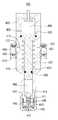
도2는 본 발명의 제2 실시예에 따른 무침 주사 장치(200)를 설명하기 위한 도면이다.2 is a diagram for explaining a
도면을 참조하면, 제2 실시예에 따른 무침 주사 장치(200)는 주사장치 본체부(210), 진동 생성부(230), 및 약물 챔버(240)를 포함할 수 있다. 주사장치 본체부(210)는 내부에 제1 공간(211)과 제2 공간(212)을 가지며 그 사이에 피스톤(220)이 배치되어 있다.Referring to the drawings, the
주사장치 본체부(210)의 상부에는 진동 생성부(230)가 결합되어 있고, 진동 생성부(230)의 진동판(232)이 제1 공간(211) 내에 배치되어 있고, 제1 공간(211)은 휘발성 액체로 채워져 있다. 약물 챔버(240)에 수용된 약물은 공급관(250)을 통해 주사장치 본체부(210)의 제2 공간(212)으로 공급될 수 있고, 제2 공간(212) 내의 약물은 휘발성 액체의 팽창에 의한 피스톤(220)의 가압에 의해 노즐(214)을 통해 외부로 분사될 수 있다.The
이와 같이 제2 실시예에 따른 주사장치 본체부(210), 진동 생성부(230), 및 약물 챔버(240)는 각각 도1의 주사장치 본체부(110), 진동 생성부(130), 및 약물 챔버(140)와 동일 또는 유사한 구성과 기능을 가지므로 자세한 설명을 생략한다.As described above, the injection device
제1 실시예와 비교할 때, 제2 실시예의 무침 주사 장치(200)는 휘발성 액체 공급 및 배출 시스템(260)을 더 구비한 점에 차이가 있다. 일 실시예에서 휘발성 액체 공급 및 배출 시스템(260)은 제1 탱크(261), 제2 탱크(262), 및 하나 이상의 밸브(263)를 포함할 수 있다.Compared with the first embodiment, the
제1 탱크(261)는 주사장치 본체부(210)의 제1 공간(211)으로 공급할 휘발성 액체를 수용하는 탱크이고, 제2 탱크(262)는 제1 공간(211)으로부터 배출되는 휘발성 액체를 수용하는 탱크이다. 밸브(263)는 제1 공간(211)과 제1 탱크(261) 사이의 경로("제1 경로") 및 제1 공간(211)과 제2 탱크(262) 사이의 경로("제2 경로")를 각각 개폐하는 동작을 한다. 밸브(263)는 하나 이상의 개폐밸브를 포함할 수 있으며, 도시한 일 실시예에서 밸브(263)는 하나의 2-way 밸브로 구현될 수 있다.The
도면에 도시하지 않았지만 무침 주사 장치(200)는 밸브(263)의 개폐 동작을 제어하는 제어부(도시 생략)을 더 포함할 수 있다. 일 실시예에서 이 제어부는, 제1 공간(211)의 휘발성 액체의 팽창에 의해 피스톤(220)이 제2 공간측으로 이동하는 동안 상기 제1 경로와 제2 경로를 폐쇄하도록 밸브(263)를 제어할 수 있다. 또한 일 실시예에서 제어부는, 제2 공간측으로 움직였던 피스톤(220)이 제1 공간측으로 복귀하는 동안 제1 공간(211)과 제2 탱크(262) 사이의 제2 경로를 개방하고 피스톤(220)이 제1 공간측으로 복귀한 이후에는 제1 공간(211)과 제1 탱크(261) 사이의 제1 경로를 개방하여 제1 탱크(261)의 휘발성 액체를 제1 공간(211)으로 주입하도록 밸브(263)를 제어할 수 있다.Although not shown in the drawing, the
구체적으로, 제2 실시예에 따른 휘발성 액체 공급 및 배출 시스템(260)을 구비한 무침 주사 장치(200)는 아래와 같이 약물 분사 동작을 복수회 반복할 수 있다.Specifically, the
먼저, 진동 생성부(230)가 동작하기 직전, 즉 피스톤(220)이 제1 공간(211)에 충전된 휘발성 액체의 압력과 탄성부재(217)의 탄성력이 균형을 이루는 위치(이하 '제1 위치'라 함)에 위치한다. 이 제1 위치는 예컨대 피스톤(220)이 스토퍼(218)에 닿을 때의 위치(최대 상승 위치)이거나 또는 최대 상승 위치보다 아래쪽의 위치일 수 있다. 피스톤(220)이 이 제1 위치에 있을 때 진동 생성부(230)가 동작을 개시하여 휘발성 액체에 고주파 진동을 인가한다. 휘발성 액체에 고주파 진동이 인가되어 휘발성 액체가 기화하면서 피스톤(220)을 제2 공간(212)측으로 밀어낸다.First, just before the
피스톤(220)이 제2 공간(212)측으로 최대로 이동하여 약물을 분사한 후, 탄성부재(217)의 탄성력에 의해 제1 공간(211)측으로 복귀한다. 이 때 피스톤(220)이 복귀하는 동안 밸브(263)의 동작에 의해 제2 탱크(262)과 제1 공간(211)의 경로가 개방되고, 기화되어 팽창되었던 휘발성 액체의 적어도 일부가 밸브(263)를 통과하여 제2 탱크(262)로 배출된다.After the
피스톤(220)이 복귀했을 때 밸브(263)의 동작에 의해 제2 탱크(262)와 제1 공간(211) 사이의 경로를 폐쇄하고 제1 탱크(261)와 제1 공간(211) 사이의 경로를 개방하여 제1 탱크(261)의 휘발성 액체를 제1 공간(211)으로 주입할 수 있다. 제1 공간(211)은 휘발성 액체로 다시 충전되고, 그 후 상술한 약물의 분사 동작이 다시 개시될 수 있다.When the
이와 같이 휘발성 액체 공급 및 배출 시스템(260)을 구비한 제2 실시예에 따르면 휘발성 액체의 팽창에 의해 약물을 분사한 후 이 휘발성 액체를 배출하고 새로운 휘발성 액체를 공급받을 수 있기 때문에, 한번 사용된 기화된 휘발성 액체가 다시 액화할 때까지 기다릴 필요가 없으므로 약물 분사 동작을 연속적으로 수행할 수 있는 이점이 있다. 또한 이 실시예에서, 제2 탱크(262)와 제1 탱크(261)를 연결하도록 구성할 수 있고 한번 사용된 기화된 휘발성 액체를 제2 탱크(262)에서 액화시킨 후 제1 탱크(261)로 다시 공급하여 반복 사용할 수도 있으므로, 휘발성 액체의 낭비 없이 약물 분사의 연속 동작을 수행하는 이점이 있다.According to the second embodiment having the volatile liquid supplying and discharging
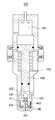
도3은 본 발명의 제3 실시예에 따른 무침 주사 장치를 설명하기 위한 도면이다.3 is a diagram for explaining a needleless injection device according to a third embodiment of the present invention.
도면을 참조하면, 제3 실시예에 따른 무침 주사 장치(300)는 주사장치 본체부(310), 진동 생성부(330), 및 약물 챔버(340)를 포함할 수 있으며, 이러한 구성요소들은 각각 도1의 주사장치 본체부(110), 진동 생성부(130), 및 약물 챔버(140)와 동일 또는 유사한 구성과 기능을 가지므로 자세한 설명을 생략한다.Referring to the drawings, the
제1 실시예와 비교할 때, 제3 실시예의 무침 주사 장치(300)는 피스톤(320)의 움직임을 제한하는 스토퍼(360)를 더 구비하는 점에 차이가 있다. 도시한 실시예에서 무침 주사 장치(300)는 피스톤(320)의 이동을 제한하는 스토퍼(360) 및 스토퍼(360)를 움직이는 구동부(365)를 더 포함한다. 일 실시예에서 스토퍼(360)는 주사장치 본체부(310)의 내측 표면에 설치되어 주사장치 본체부(310)의 중심축을 향해 돌출되도록 구성될 수 있다. 구동부(365)는 스토퍼(360)와 연결되어 있으며, 스토퍼(360)를 주사장치 본체부(310)의 내측 표면 안쪽으로 이동시키도록 동작할 수 있다. 일 실시예에서 구동부(365)는 예컨대 직선운동을 하는 리니어 모터나 유압 액추에이터 등의 공지의 기술로 구현될 수 있다. 또한 도면에 도시하지 않았지만 무침 주사 장치(300)는 구동부(365)의 동작을 제어하는 제어부(도시 생략)를 더 포함할 수 있다.Compared with the first embodiment, the
이러한 제3 실시예에 따르면, 진동 생성부(330)가 동작을 개시하여 소정 시간이 경과하기 전까지 스토퍼(360)가 본체부(310)의 내측 표면으로 돌출되어 위치하여 피스톤(320)이 아래로 움직이지 않도록 한다. 그 후 진동 생성부(330)의 동작 개시로부터 소정 시간이 경과하면 제어부가 구동부(365)를 제어하여 스토퍼(360)를 주사장치 본체부(310)의 내측 표면 안쪽으로 이동시키고, 이에 따라 피스톤(320)이 팽창된 휘발성 액체의 압력에 의해 제2 공간측으로 움직여서 약물을 분사하게 된다.According to this third embodiment, the
대안적 실시예에서 무침 주사 장치(300)는 제1 공간(311) 내의 휘발성 액체의 압력을 측정하는 압력센서(도시 생략)를 더 포함할 수 있고, 제어부가 이 압력센서의 측정 결과에 따라 구동부(365)의 동작을 제어할 수도 있다. 예를 들어, 진동 생성부(330)가 동작하기 시작하면 압력센서가 제1 공간 내의 휘발성 액체의 압력을 측정하여 이 측정값을 제어부로 전달하고, 제어부는 이 측정값이 기설정된 소정 압력보다 크면 제어부가 구동부(365)를 동작시켜 스토퍼(360)를 주사장치 본체부(310)의 내측 표면 안쪽으로 이동시키고 이에 따라 피스톤(320)이 팽창된 휘발성 액체의 압력에 의해 제2 공간측으로 움직여서 약물을 분사할 수 있다.In an alternative embodiment, the
또한 다른 대안적 실시예에서, 무침 주사 장치(300)는 스토퍼(360) 및 이 스토퍼(360)를 수동으로 조작하는 장치를 구비할 수도 있다. 즉 이 대안적 실시예에서 무침 주사 장치(300)는 구동부(365)가 없으며, 스토퍼(360)를 사용자가 필요에 따라 수동으로 조작할 수 있도록 구성할 수 있다. 예를 들어, 사용자는 고주파 진동에 의해 휘발성 액체가 충분히 팽창한 것을 예컨대 압력센서 등으로 확인한 후 또는 진동 생성부의 동작 개시 시점으로 소정 시간의 경과를 확인한 후 사용자가 원하는 임의의 시점에 스토퍼(360)를 움직여서 피스톤(320)을 작동시킬 수 있고, 따라서 약물 분사 시점을 사용자가 조절할 수 있는 이점이 있다.Further, in another alternative embodiment, the
상기와 같이 스토퍼(360)를 구비한 제3 실시예에 따르면 휘발성 액체가 팽창하여 충분한 압력으로 피스톤(320)을 가압할 수 있을 때까지 피스톤(320)의 움직임을 제한하였다가 높은 압력이 되었을 때 피스톤(320)을 동작시키기 때문에 높은 분사압력으로 약물을 생체 내로 주입할 수 있다.According to the third embodiment provided with the
이제 도4 내지 도6을 참조하여 본 발명의 제4 실시예에 따른 무침 주사 장치를 설명하기로 한다. 도4 내지 도6은 제4 실시예에 따른 무침 주사 장치의 개략도로서, 도4와 도5는 각각 약물 장전 상태와 약물 발사 상태의 무침 주사 장치의 단면을 개략적으로 도시하였고, 도6은 무침 주사 장치의 외관을 개략적으로 도시하였다.A needleless injection device according to a fourth embodiment of the present invention will now be described with reference to FIGS. 4 to 6. 4 to 6 are schematic diagrams of a needleless injection device according to a fourth embodiment, FIGS. 4 and 5 schematically show cross-sections of the needleless injection device in a drug loading state and a drug launch state, respectively, and FIG. 6 is a needleless injection device. The appearance of the device is schematically shown.
도4와 도5를 참조하면, 제4 실시예에 따른 무침 주사 장치(400)는 하부 하우징(410), 상부 하우징(420), 및 조절너트(430)로 이루어진 본체부를 포함한다. 도1 내지 도3에서와 같이 무침 주사 장치(400)에도 진동 생성부(130,230) 및 약물 챔버(140,240,340)가 구비될 수 있으나 설명의 편의를 위해 생략하였다. 또한 무침 주사 장치(400) 내부로 휘발성 액체를 공급하고 배출하기 위한 휘발성 액체 공급 및 배출 시스템(도2의 260)을 구비할 수 있으나 역시 설명의 편의를 위해 생략하였음을 이해할 것이다.4 and 5, the
도시한 실시예에서, 주사장치 본체부는 하부 하우징(410), 상부 하우징(420), 및 조절너트(430)를 포함한다. 상부 하우징(420)은 내부에 제1 공간(401)을 포함한다. 제1 공간(401)은 휘발성 액체가 적어도 부분적으로 충전된다. 휘발성 액체는 고주파 진동에 의해 팽창하여 피스톤(450)을 아래 방향으로 가압할 수 있다.In the illustrated embodiment, the injection device main body includes a
하부 하우징(410)은 내부에 피스톤(450)의 이동 경로 및 제2 공간(402)을 포함한다. 제2 공간(402)은 약물이 충전되는 공간이며, 약물은 약물 주입구(414)를 통해 제2 공간(402)로 주입될 수 있다. 도4에 도시하지 않았지만 약물 주입구(414)는 약물 챔버(140,240,340)에 연결될 수 있다.The
도시한 실시예에서 상부 하우징(420) 내부의 제1 공간(401)의 아래쪽에는 피스톤(450)의 헤드가 움직일 수 있는 공간이 있으며, 이 피스톤 헤드의 이동 공간과 제1 공간(401) 사이에는 단차(428)가 형성될 수 있다. 단차(428)는 예컨대 도3의 상부 스토퍼(318)와 유사한 기능을 가질 수 있다. 즉 피스톤(450)의 복귀시 과도한 상승을 방지하여 제1 공간(401)을 확보할 수 있다.In the illustrated embodiment, there is a space in which the head of the
하부 하우징(410)의 상단부(412)의 내경은 상부 하우징(420)의 하단부(422)의 내경 보다 작도록 구성된다. 이 때 피스톤(450)의 피스톤 헤드의 직경이 상부 하우징(420)의 하단 영역의 내경과 같도록 구성하였으므로, 피스톤 헤드는 하우징(410)의 상단부(412)까지만 하강할 수 있다. 따라서 도시한 실시예에서 피스톤(450)은 상부 하우징(420)의 단차(428)와 하부 하우징(410)의 상단부(412) 사이의 이격 거리에 따라 상하 방향의 움직임이 제한될 수 있다.The inner diameter of the
조절너트(430)는 하부 하우징(410)과 상부 하우징(420)을 연결하는 역할을 한다. 조절너트(430)는 예컨대 통형상(또는 링(ring) 형상)의 부재일 수 있다. 도시한 실시예에서, 조절너트(430)는 하부 하우징(410)의 상단의 적어도 일부 외주면과 상부 하우징(420)의 하단의 적어도 일부 외주면을 둘러싸도록 형성될 수 있다.The
도시한 실시예에서 상부 하우징(420)의 하단부에 플랜지(421)가 형성되고, 조절너트(430)의 내주면에는 이 플랜지(420)와 맞물리는 체결홈(431)이 형성되어 있다. 이에 따라 플랜지(420)가 체결홈(431)에 안착되어 체결됨으로써, 조절너트(430)가 상부 하우징(420)에 회전가능하게 체결될 수 있다.In the illustrated embodiment, a
조절너트(430)의 내주면 중 체결홈(431) 아래쪽의 내주면에는 하부 하우징(410)과 결합하기 위한 구조가 형성되어 있다. 도시한 실시예에서 조절너트(430)와 하부 하우징(410)은 나사 결합 또는 이와 유사한 방식의 결합에 의해 체결된다. 일 실시예에서 하부 하우징(410)의 상부의 외주면에 나사산과 같은 요철 형상(413)이 형성되어 있고, 조절너트(430)의 내주면에는 이에 맞물리면서 결합하도록 볼(433)과 같은 돌출부가 형성되어 있다. 볼(433)은 조절너트(430)의 내주면을 따라 복수개 설치될 수 있고, 하부 하우징(410)의 요철 형상(413)의 오목한 영역(그루브)에 안착되면서 조절너트(430)와 하부 하우징(410)이 체결될 수 있다. 대안적 실시예에서, 하부 하우징(410)의 상부의 외주면에 나사산과 같은 요철 형상이 형성되고, 조절너트(430)의 내주면에는 이에 맞물리는 요철 형상이 형성될 수 있다.Among the inner circumferential surfaces of the
이와 같이 조절너트(430)와 하부 하우징(410)을 나사 결합 또는 이와 유사한 방식의 결합에 의해 체결하도록 구성하여, 조절너트(430)를 하부 하우징(410)에 대해 회전하면서 조절 너트(430)와 하부 하우징(410)이 결합하는 결합 길이를 가변으로 조절할 수 있다.In this way, the
대안적 실시예에서, 조절 너트(430)와 상부 하우징(420)이 결합하는 결합 길이를 가변으로 조절하도록 구성할 수도 있다. 예를 들어, 상술한 나사결합 또는 이와 유사한 방식의 결합 구조를 조절너트(430)와 상부 하우징(420)에 적용할 수 있다. 이 경우, 하부 하우징(410)의 상단부에 플랜지를 형성하고 조절너트(430)의 체결홈(431)과 하부 하우징의 플랜지와 결합하도록 함으로써 조절너트(430)가 하부 하우징에 대해 회전가능하게 체결시킬 수 있다.In an alternative embodiment, the
또 다른 대안적 실시예에서는, 예컨대 조절너트(430)와 하부 하우징(410) 사이 및 조절너트(430)와 상부 하우징(420) 사이를 각각 나사결합 또는 이와 유사한 방식의 결합 구조로 체결할 수 있고, 이에 따라 조절너트(430)와 하부 하우징(410)과의 결합 길이 및 조절너트(430)와 상부 하우징(420)과의 결합 길이를 각각 개별적으로 조절할 수도 있다.In another alternative embodiment, for example, the
조절너트(430)와 하부 하우징(410) 또는 상부 하우징(420) 중 적어도 하나와의 결합 길이를 조절하면 조절너트(430)에 의해 하부 하우징(410)과 상부 하우징(420) 사이의 간격이 달라지며, 따라서 피스톤(450)이 탄성부재(417)의 탄성력에 의해 제2 공간(402) 쪽으로 더 이동하거나 제2 공간(402)에서 멀어지는 방향으로 이동하여 위치한다. 따라서 조절너트(430)와 하부 또는 상부 하우징(410,420) 중 적어도 하나와의 결합 길이를 조절함으로써 제2 공간(402)의 부피를 증감시킬 수 있으므로, 생체 내로 한번에 주입하는 약물의 주입량을 조절할 수 있다.When the coupling length between the
일 실시예에서, 도3에 도시한 하부 스토퍼(360) 및 구동부(365)가 도4의 실시예에 적용될 수도 있다. 이 경우 상부 하우징(420)은 피스톤(450)이 아래로 움직이지 않도록 움직임을 제한하는 스토퍼 및 이 스토퍼를 구동하는 구동부 또는 수동으로 스토퍼를 움직이는 장치를 더 포함할 수 있다. 스토퍼 및 구동부는 도3의 스토퍼(360) 및 구동부(365)와 동일 또는 유사한 기능을 하므로 설명을 생략한다.In an embodiment, the
또한 도시한 실시예에서 상부 하우징(420)은 휘발성 액체를 외부에서 공급받거나 외부로 배출하기 위한 배출구(423)를 포함한다. 배출구(423)는 예컨대 도2의 휘발성 액체 공급 및 배출 시스템(도2의 260)과 연결될 수 있음을 이해할 것이다.In addition, in the illustrated embodiment, the
하부 하우징(410)은 측면에 공기 배출구(415)를 포함할 수 있다. 공기 배출구(415)는 예컨대 도1의 공기 배출구(115)와 동일 또는 유사한 기능을 하기 위한 것이며 상세한 설명은 생략한다.The
하부 하우징(410)의 하단부에는 제2 공간(401) 내의 약물을 외부로 분사하기 위한 노즐 구조를 포함할 수 있다. 일 실시예에서 노즐 구조는 예컨대 도1 내지 도3에 도시한 구조와 유사하게 하부 하우징(410)의 하부면에 소정 직경을 갖는 노즐(114,214,314)을 포함할 수 있다.A lower end of the
도4에서는 대안적 실시예에 따른 노즐 구조를 도시하였다. 이 대안적 실시예에 따르면 하부 하우징(410)의 하단부에 캡(cap) 형상의 노즐부(440)가 부착된다. 노즐부(440)는 상하 방향으로 소정 범위 내에서 움직일 수 있도록 하부 하우징(410)에 결합된다. 이 때 노즐부(440)와 하부 하우징(410)의 하부면 사이에 하나 이상의 탄성부재(445)가 배치될 수 있다. 따라서 노즐부(440)에 소정 크기 이상의 힘을 가하면 노즐부(440)가 하부 하우징(410)쪽으로 움직여서 도5에 도시한 것처럼 하부 하우징(410)의 하단부와 밀착되고, 외부의 힘이 없어지면 탄성부재(445)의 탄성력에 의해 도4와 같이 하부 하우징(410)으로부터 소정 거리 이격된다.Fig. 4 shows a nozzle structure according to an alternative embodiment. According to this alternative embodiment, a cap-shaped
도시한 실시예에서 하부 하우징(410)의 하부면에는 수직 방향의 관통구(411)가 형성되고, 캡 형상의 노즐부(440) 중앙부에는 관통구(411)에 끼워맞춤되어 관통구(411)를 따라 수직 방향으로 움직일 수 있는 돌출부(442)가 형성된다. 노즐부(440)와 돌출부(442)는 일체로 형성될 수도 있고 개별적으로 형성된 후 노즐부(440)에 결합될 수도 있다. 돌출부(442)는 상하 방향으로 약물이 통과하는 유로(443)를 포함한다. 유로(443)의 상부 끝은 돌출부(442)의 측면에 형성되고 유로(443)의 하부 끝은 노즐부(440)의 하부면에 형성된 노즐(441)과 정렬되도록 구성될 수 있다. 따라서 도4에 도시한 것처럼 노즐부(440)가 하부 하우징(410)에서 이격된 상태에서, 유로(443)의 상부 끝이 하부 하우징(410)의 관통구(411) 내에 위치하고 있어 유로(443)가 폐쇄되어 있으며 따라서 제2 공간(402)의 약물이 외부로 배출되지 못한다.In the illustrated embodiment, a through
그러나 외부로부터 힘이 작용하여 도5와 같이 노즐부(440)가 하부 하우징(410)의 하단부에 밀착하게 되면 유로(443)의 상부 끝이 제2 공간(402) 중에 개방되고, 따라서 이 상태에서 피스톤(450)이 아래로 움직이면 제2 공간(402) 내의 약물이 유로(443)와 노즐(441)을 통과하여 외부로 분사될 수 있다. 따라서, 예를 들어 동물의 생체 내로 약물을 분사하고자 할 경우, 노즐부(440)의 하부면을 동물의 피부에 대고 무침 주사 장치(400)의 본체부를 누르면 이 누르는 힘에 의해 노즐부(440)가 도5에서와 같이 하부 하우징(410)의 하단부에 밀착하게 되고, 이 상태에서 고주파 진동에 의해 피스톤(450) 구동에 의한 약물 분사에 의해 약물을 생체 내로 주입할 수 있다.However, when the
한편 도시한 실시예에서 제2 공간(402)의 내부에 볼(447)을 더 포함할 수 있다. 볼(447)의 예컨대 금속 재질의 금속구일 수 있고 볼(447)의 직경은 관통구(411)보다 큰 것이 바람직하다. 이러한 구성에 따른 볼(447)은 제2 공간(402)의 약물이 유로(443)를 통해 외부로 배출되는 것을 방지한다. 즉 도4에서와 같이 노즐부(440)가 하부 하우징(410)에서 이격된 경우 볼(447)이 관통구(411)를 막게 되므로 제2 공간(402)의 약물이 관통구(411)을 통해 외부로 배출되는 것을 방지할 수 있다.Meanwhile, in the illustrated embodiment, a
일 실시예에서 볼(447)은 제2 공간(402) 내에서 자유롭게 움직일 수 있도록 배치될 수 있다. 대안적 실시예에서 볼(447)이 임의의 탄성부재나 와이어 등에 의해 제2 공간(402)을 구성하는 하부 하우징(410)의 내부 벽면이나 또는 돌출부(442) 등에 연결되어 있을 수 있고, 이 경우 무침 주사 장치(400)를 거꾸로 위치시키거나 움직이더라도 볼(447)이 제2 공간(402) 내에서 움직이는 범위를 제한할 수 있다.In one embodiment, the
한편 도6은 도4와 도5의 무침 주사 장치의 외관을 개략적으로 도시하였다. 상술한 바와 같이 무침 주사 장치의 본체부가 하부 하우징(410), 상부 하우징(420), 및 조절너트(430)로 구성된다. 하부 하우징(410)의 하부에는 노즐부(440)가 상하방향으로 이동가능하게 부착된다.Meanwhile, FIG. 6 schematically shows the appearance of the needleless injection device of FIGS. 4 and 5. As described above, the body portion of the needleless injection device includes a
조절너트(430)와 하부 하우징(410)은 도4에 도시한 것처럼 나사결합 또는 이와 유사한 방식의 결합으로 체결되어 있으며, 따라서 조절너트(430)를 회전함에 따라 조절너트(430)와 하부 하우징(410) 사이의 체결 길이가 달라지고 제2 공간(402)의 부피를 증감할 수 있다. 이 때 도시한 것처럼 하부 하우징(410)의 표면에 조절 눈금이 새겨져 있으며, 각 눈금은 조절너트(430)의 하단부가 이 눈금과 일치한 높이에 왔을 때의 제2 공간(402)의 체적을 나타낼 수 있다. 따라서 사용자가 필요한 약물 주입량에 따라 조절너트(430)를 회전하여 해당 눈금에 맞출 수 있으므로 약물 주입량을 사용자가 쉽고 편리하게 조절할 수 있다.The
한편 도시한 실시예에 따르면 노즐부(440)가 의도치 않게 상부로 움직여서 제2 공간(402)이 개방되는 것을 방지하는 잠금장치 구조를 포함할 수 있다. 도시한 실시예에서 노즐부(440)는 표면에 소정 형상의 홈이나 관통구로 형성된 가이드홈(448)을 포함한다. 가이드홈(448)은 예를 들어 수평 및 수직 방향으로 소정 길이로 형성될 수 있고 예컨대 도면에 도시한 것처럼 "ㄱ"자 형태의 홈일 수 있다. 또한 하부 하우징(410)의 외부 표면에는 돌출편(418)이 돌출되어 있고, 돌출편(418)은 가이드홈(448)의 홈에 끼워져서 가이드된다.Meanwhile, according to the illustrated embodiment, the
이러한 구성에 따르면 돌출편(418)이 도6에 도시한 잠금 위치, 즉 가이드홈(448)의 수평방향의 홈에 위치하고 있으면 돌출편(418)이 상하로 움직일 수 없으므로 노즐부(440)가 상하방향으로 움직이는 것을 방지할 수 있다. 무침 주사 장치를 사용하고자 할 경우 돌출편(418)이 가이드홈(448)의 수직 방향의 홈에 위치하도록 노즐부(440)를 왼쪽으로 회전시켜 잠금해제한다. 이 잠금해제 위치에서 노즐부(440)가 상하방향으로 움직일 수 있으므로, 예컨대 사용자가 노즐부(440)를 동물이나 신체의 피부에 접촉한 채 무침 주사 장치의 본체부를 누르면 도5에 도시한 것처럼 노즐부(440)가 하부 하우징(410)에 밀착하면서 유로(443)가 개방되어 약물을 분사할 수 있다.According to this configuration, if the protruding
상술한 제4 실시예의 무침 주사 장치(400)를 사용하는 예시적인 약물 분사 방법을 설명하기로 한다.An exemplary drug injection method using the
우선, 앞선 약물 분사 이후 피스톤(450)이 탄성부재(417)의 탄성력에 의해 상방향으로 복귀하면서 약물이 약물 주입구(414)를 통해 제2 공간(402)으로 흡입되어 채워진다. 그 후 다음번 약물 분사를 위해 진동생성부(130)를 동작한다. 한편 약물을 충전하고 진동생성부(130)를 동작시키는 동안 사용자는 가이드홈(448)을 따라 노즐부(440)를 회전시켜 노즐부(440)가 상하 방향으로 움직이지 않도록 잠금 상태로 설정할 수 있다.First, after the previous drug injection, the
진동생성부(130)의 동작에 의해 제1 공간(401)의 휘발성 액체가 팽창하여 피스톤(450)을 하방으로 가압한다. 그러나 도4에 도시한 것처럼 제2 공간(402)의 볼(447)이 관통구(411)를 막고 있으므로 제2 공간(402)의 압력이 상승되지만 피스톤(450)은 움직이지 않는 대기상태에 놓이게 된다The volatile liquid in the
그 후 사용자가 노즐부(440)를 회전시켜 잠금해제 상태로 두고 동물이나 신체의 피부에 노즐부(440)를 접촉하여 무침주사 장치 본체를 누르면 도5에서와 같이 노즐부(440)가 상부로 이동하여 하부 하우징(410)에 밀착하면서 유로(443)가 제2 공간(402)과 연통하게 되고, 이에 따라 피스톤(450)이 하방으로 움직이면서 제2 공간(402)의 약물을 노즐(441)을 통해 분사할 수 있다.After that, when the user rotates the
도7은 본 발명의 제5 실시예에 따른 무침 주사 장치를 설명하기 위한 도면이다7 is a view for explaining a needleless injection device according to a fifth embodiment of the present invention
도면을 참조하면, 제5 실시예에 따른 무침 주사 장치(500)는 주사장치 본체부(510) 및 본체부(510)의 하부에 결합된 노즐부(540)를 포함한다. 본체부(510)는 상부에 제1 공간(501) 및 하부에 제2 공간(502)를 갖는다.Referring to the drawings, a
제1 공간(501)에 배치되는 진동 생성부는 도1 내지 도3을 참조하여 설명한 진동 생성부(130, 230, 330)와 동일하므로 설명을 생략한다. 또한 제2 공간(502) 하부에 결합되는 노즐부(540)는 도4 내지 도6을 참조하여 설명한 노즐부(440)와 동일하므로 설명을 생략한다.The vibration generating unit disposed in the
제5 실시예에 따른 무침 주사 장치(500)는 제1 및 제2 공간(501, 502) 사이에 탄성체로 이루어진 피스톤(520)을 포함하는 점에서 제1 내지 제4 실시예와 차이가 있다. 탄성체의 피스톤(520)은 제1 내지 제4 실시예의 강성을 갖는 피스톤(120, 220, 320, 450)을 대체하여 이와 동일한 기능을 수행할 수 있다. 피스톤(520)은 순간 압력에 의해 형상이 자유롭게 변형될 수 있는 탄성체의 겔 또는 고무 재질로 만들어질 수 있다.The
도7(a)와 같이 제2 공간(502)에 약물을 장전한 대기상태에 있을 때 피스톤(520)은 원래의 최초 형상을 가지며 제1 공간(501)과 제2 공간(502) 사이에 배치되어 있다가, 제1 공간(502) 내에 순간팽창 압력이 발생하면 도7(b)와 같이 피스톤(520)의 형상이 변형되며 제2 공간(502)으로 움직이고 제2 공간(502) 내의 약물을 노즐(541)을 통해 방출할 수 있다. 그 후 제1 공간(501)의 팽창 압력이 사라지면 피스톤(520)은 자체의 탄성력에 의해 다시 도7(a)와 같은 형상으로 되돌아가서 복귀할 수 있다.When in the standby state in which the drug is loaded in the
이와 같이 제5 실시예에 따르면 고체의 강성을 갖는 피스톤 대신 탄성체의 피스톤(620)을 사용함으로써 피스톤(120, 220, 320, 450) 및 스프링(117, 217, 317, 417)을 대체할 수 있으므로 무침 주사 장치의 구조를 더 간단화 할 수 있다.As described above, according to the fifth embodiment, the
이상과 같이 본 발명이 속하는 분야에서 통상의 지식을 가진 자라면 이러한 명세서의 기재로부터 다양한 수정 및 변형이 가능함을 이해할 것이다. 예를 들어 도2는 휘발성 액체 공급 및 배출 시스템(260)만 구비한 구성이고 도3은 스토퍼(360)만 구비만 구성이지만, 다른 대안적 실시예에서 무침 주사 장치가 휘발성 액체 공급 및 배출 시스템(260)과 스토퍼(360)를 모두 구비하는 것도 가능하다. 또한 도1 내지 도3의 무침주사 장치 본체부(110,210,310)를 도4와 같이 하부 하우징(410), 상부 하우징(420), 및 조절너트(430)로 구성하여 약물 주입량을 조절할 수 있도록 구성할 수도 있고, 도1 내지 도3의 본체부(110,210,310)의 하단부를 도4에서와 같이 노즐부(440)로 구성할 수도 있을 것이다. 또한 도1 내지 도6의 실시예에 도7의 탄성체 피스톤(620)을 적용할 수도 있을 것이다. 그러므로 본 발명의 범위는 설명된 실시예에 국한되어 정해져서는 아니되며 후술하는 특허청구범위뿐 아니라 이 특허청구범위와 균등한 것들에 의해 정해져야 한다.As described above, those of ordinary skill in the field to which the present invention belongs will understand that various modifications and variations are possible from the description of this specification. For example, Figure 2 is a configuration having only a volatile liquid supply and
100, 200, 300, 400: 무침 주사 장치
110, 210, 310: 주사장치 본체부
120, 220, 320, 450, 520: 피스톤
130, 230, 330: 진동 생성부
140, 240, 340: 약물 챔버100, 200, 300, 400: needleless injection device
110, 210, 310: injection device main body
120, 220, 320, 450, 520: piston
130, 230, 330: vibration generating unit
140, 240, 340: drug chamber
Claims (17)
Translated fromKorean길이방향을 따라 제1 공간(111)과 제2 공간(112)을 갖는 통형상의 주사장치 본체부(110);
상기 주사장치 본체부의 제2 공간측의 단부에 형성된 노즐(114);
상기 제1 공간과 제2 공간 사이에 배치되며 상기 주사장치 본체부의 길이 방향을 따라 이동가능한 피스톤(120);
상기 제1 공간(111)에 수용되고 고주파 진동에 의해 기화될 수 있는 휘발성 액체;
상기 휘발성 액체에 고주파 진동을 인가하는 진동 생성부(130);
상기 휘발성 액체를 수용하는 제1 탱크(261);
상기 제1 공간으로부터 배출되는 휘발성 액체를 수용하는 제2 탱크(262);
상기 제1 공간과 상기 제1 탱크 사이의 제1 경로 및 상기 제1 공간과 상기 제2 탱크 사이의 제2 경로를 개폐하는 적어도 하나의 밸브(263); 및
상기 밸브(263)의 개폐를 제어하는 제1 제어부;를 포함하고,
상기 진동 생성부의 고주파 진동에 의해 상기 휘발성 액체의 적어도 일부가 기화하고 부피가 팽창하여 상기 피스톤을 가압함으로써, 상기 제2 공간(112)에 수용된 약물을 상기 노즐을 통해 분사하도록 구성된 것을 특징으로 하는 무침 주사 장치.As a needleless injection device for injecting drugs,
A cylindrical injection device main body 110 having a first space 111 and a second space 112 along the longitudinal direction;
A nozzle (114) formed at an end of the injection device main body on the second space side;
A piston (120) disposed between the first space and the second space and movable along the longitudinal direction of the main body of the injection device;
A volatile liquid accommodated in the first space 111 and capable of being vaporized by high frequency vibration;
A vibration generating unit 130 for applying high-frequency vibration to the volatile liquid;
A first tank (261) containing the volatile liquid;
A second tank (262) for receiving the volatile liquid discharged from the first space;
At least one valve (263) for opening and closing a first path between the first space and the first tank and a second path between the first space and the second tank; And
Including; a first control unit for controlling the opening and closing of the valve 263,
At least a portion of the volatile liquid vaporizes and expands in volume by the high frequency vibration of the vibration generating unit to pressurize the piston, thereby spraying the drug contained in the second space 112 through the nozzle. Injection device.
상기 진동 생성부는 수 KHz 내지 수백 KHz 사이의 주파수를 갖는 진동을 생성하는 것을 특징으로 하는 무침 주사 장치.The method of claim 1,
The vibration generating unit generates a vibration having a frequency between several KHz to several hundred KHz without needleless scanning device.
압전 스택(131);
상기 압전 스택에 연결되고 상기 제1 공간 내에 배치된 진동판(132); 및
상기 압전 스택에 전원을 인가하는 전원부(150);를 포함하는 것을 특징으로 하는 무침 주사 장치.The method of claim 1, wherein the vibration generating unit,
Piezoelectric stack 131;
A vibration plate 132 connected to the piezoelectric stack and disposed in the first space; And
And a power supply unit 150 for applying power to the piezoelectric stack.
상기 휘발성 액체가 디에틸에테르, 이황화탄소, 아세트알데히드, 및 산화프로필렌 중 하나를 포함하는 것을 특징으로 하는 무침 주사 장치.The method of claim 1,
The volatile liquid is a needleless injection device, characterized in that it contains one of diethyl ether, carbon disulfide, acetaldehyde, and propylene oxide.
상기 휘발성 액체의 팽창에 의해 제2 공간측으로 이동된 피스톤을 제1 공간측으로 복귀시키도록 동작하는 탄성부재(117);를 더 포함하는 것을 특징으로 하는 무침 주사 장치.The method of claim 1,
And an elastic member (117) operable to return the piston moved to the second space side to the first space side by the expansion of the volatile liquid.
약물을 저장하는 약물 챔버(140);
상기 약물 챔버(140)에서 상기 제2 공간(112)으로 약물을 공급하는 공급관(150); 및
상기 공급관에 설치되고, 상기 제2 공간으로 공급되는 약물이 상기 약물 챔버로 역류하지 않도록 구성된 체크 밸브(155);를 더 포함하는 것을 특징으로 하는 무침 주사 장치.The method of claim 1,
A drug chamber 140 for storing drugs;
A supply pipe 150 for supplying a drug from the drug chamber 140 to the second space 112; And
And a check valve (155) installed in the supply pipe and configured to prevent a drug supplied to the second space from flowing back into the drug chamber.
상기 제1 제어부가, 상기 휘발성 액체의 팽창에 의해 상기 피스톤이 상기 제2 공간측으로 이동하는 동안 상기 제1 경로와 상기 제2 경로를 폐쇄하도록 상기 밸브를 제어하는 것을 특징으로 하는 무침 주사 장치.The method of claim 1,
And the first control unit controls the valve to close the first path and the second path while the piston moves toward the second space due to expansion of the volatile liquid.
상기 제1 제어부가, 상기 피스톤이 상기 제1 공간측으로 복귀하는 동안 상기 제2 경로를 개방하고, 상기 피스톤이 상기 제1 공간측으로 복귀한 후 상기 제1 경로를 개방하여 상기 제1 탱크의 휘발성 액체를 상기 제1 공간으로 주입하도록 상기 밸브를 제어하는 것을 특징으로 하는 무침 주사 장치.The method of claim 8,
The first control unit opens the second path while the piston returns to the first space side, and opens the first path after the piston returns to the first space side, so that the volatile liquid of the first tank The needleless injection device, characterized in that controlling the valve so as to inject into the first space.
상기 주사장치 본체부의 내측 표면에 설치되고 상기 주사장치 본체부의 중심축을 향해 돌출되어 상기 피스톤의 이동을 제한하는 스토퍼(360);
상기 스토퍼와 연결되고 상기 스토퍼를 상기 주사장치 본체부의 내측 표면 안쪽으로 이동시키도록 동작하는 구동부(365); 및
상기 구동부의 동작을 제어하는 제2 제어부;를 더 포함하는 것을 특징으로 하는 무침 주사 장치.The method of claim 1,
A stopper 360 installed on an inner surface of the main body of the injection device and protruding toward a central axis of the main body of the injection device to limit movement of the piston;
A driving unit (365) connected to the stopper and operative to move the stopper to an inner surface of the main body of the injection device; And
And a second control unit for controlling the operation of the driving unit.
상기 제2 제어부가, 상기 진동 생성부의 동작 개시로부터 소정 시간이 경과한 후 상기 스토퍼를 상기 주사장치 본체부의 내측 표면 안쪽으로 이동시키도록 상기 구동부를 제어하는 것을 특징으로 하는 무침 주사 장치.The method of claim 10,
And the second control unit controls the driving unit to move the stopper to an inner surface of the main body of the injection device after a predetermined time has elapsed from the start of the operation of the vibration generating unit.
상기 제1 공간 내부의 압력을 측정하는 압력센서를 더 포함하고,
상기 제2 제어부가, 상기 압력센서의 측정값이 기설정된 소정 압력보다 클 때 상기 스토퍼를 상기 주사장치 본체부의 내측 표면 안쪽으로 이동시키도록 상기 구동부를 제어하는 것을 특징으로 하는 무침 주사 장치.The method of claim 10,
Further comprising a pressure sensor for measuring the pressure inside the first space,
And the second control unit controls the driving unit to move the stopper to an inner surface of the main body of the injection unit when the measured value of the pressure sensor is greater than a predetermined pressure.
상기 주사장치 본체부가,
내부에 상기 피스톤의 이동 경로와 상기 제2 공간을 갖는 하부 하우징(410);
내부에 상기 제1 공간을 갖는 상부 하우징(420); 및
상기 하부 하우징과 하부 하우징을 연결하는 조절너트(430);를 포함하고,
상기 조절너트(430)는 상기 하부 하우징의 상단의 적어도 일부 외주면과 상기 상부 하우징의 하단의 적어도 일부 외주면을 둘러싸도록 형성되되, 상기 하부 하우징 또는 상부 하우징 중 적어도 하나와의 결합 길이가 조절되도록 구성되고,
상기 결합 길이의 조절에 의해 상기 제2 공간의 부피가 증감하도록 구성된 것을 특징으로 하는 무침 주사 장치.The method of claim 1,
The main body of the injection device,
A lower housing 410 having the movement path of the piston and the second space therein;
An upper housing 420 having the first space therein; And
Including; an adjustment nut 430 connecting the lower housing and the lower housing,
The adjustment nut 430 is formed to surround at least a portion of an outer circumferential surface of an upper end of the lower housing and at least a portion of an outer circumferential surface of a lower end of the upper housing, and the coupling length of the lower housing or the upper housing is adjusted so ,
A needleless injection device, characterized in that the volume of the second space is increased or decreased by adjusting the coupling length.
상기 조절너트(430)가 상기 상부 하우징(420)에 회전가능하게 결합되고 상기 하부 하우징(410)과는 나사결합 방식으로 결합됨으로써, 상기 조절너트와 상기 하부 하우징과의 결합 길이가 조절가능한 것을 특징으로 하는 무침 주사 장치.The method of claim 13,
The adjustment nut 430 is rotatably coupled to the upper housing 420 and is coupled to the lower housing 410 in a screwed manner, so that the coupling length between the adjustment nut and the lower housing is adjustable. Needleless injection device made with.
상기 조절너트(430)가 상기 하부 하우징(410)에 회전가능하게 결합되고 상기 상부 하우징(420)과는 나사결합 방식으로 결합됨으로써, 상기 조절너트와 상기 상부 하우징과의 결합 길이가 조절가능한 것을 특징으로 하는 무침 주사 장치.The method of claim 13,
The adjustment nut 430 is rotatably coupled to the lower housing 410 and is coupled to the upper housing 420 in a threaded manner, so that the coupling length between the adjustment nut and the upper housing is adjustable. Needleless injection device made with.
상기 하부 하우징(410)은 하단부에 상하 방향으로 이동가능하게 겹합되며 내부에 유로(443)를 갖는 노즐부(440)를 포함하고,
상기 노즐부(440)는, 하부면에 형성된 노즐(441); 및 상기 노즐부(440) 내부에 상하방향으로 약물이 통과하기 위한 유로(443);를 포함하고,
상기 유로(443)의 상단은 상기 제2 공간과 연통하고 하단은 상기 노즐(441)과 연통하되, 상기 노즐부(440)가 하부로 이동하여 상기 하부 하우징으로부터 이격되었을 때 상기 유로가 폐쇄되고 상기 노즐부(440)가 상부로 이동하여 상기 하부 하우징에 밀착하였을 때 상기 유로가 개방되도록 구성된 것을 특징으로 하는 무침 주사 장치.The method of claim 13,
The lower housing 410 includes a nozzle portion 440 that is movably overlapped with a lower portion and has a flow path 443 therein,
The nozzle unit 440 may include a nozzle 441 formed on a lower surface; And a passage 443 for passing the drug in the vertical direction inside the nozzle part 440,
The upper end of the flow path 443 communicates with the second space and the lower end communicates with the nozzle 441, but when the nozzle part 440 moves downward and is spaced apart from the lower housing, the flow path is closed and the No needleless injection device, characterized in that the flow path is opened when the nozzle unit 440 moves upward and comes into close contact with the lower housing.
수평 및 수직 방향으로 상기 노즐부(440)의 표면에 형성된 가이드홈(448); 및
상기 가이드홈(448)에 대응하는 상기 하부 하우징(410)의 외부 표면에 돌출 형성된 돌출편(418);을 더 포함하고,
상기 돌출편(418)이 상기 가이드홈(448)을 따라서 움직이도록 구성함으로써, 상기 노즐부(440)가 수직방향으로 이동할 수 없는 잠금 위치 및 수직방향으로 이동할 수 있는 잠금해제 위치 사이에서 움직이도록 구성한 것을 특징으로 하는 무침 주사 장치.The method of claim 16,
A guide groove 448 formed on the surface of the nozzle part 440 in horizontal and vertical directions; And
A protrusion piece 418 protruding from the outer surface of the lower housing 410 corresponding to the guide groove 448; further includes,
By configuring the protruding piece 418 to move along the guide groove 448, the nozzle unit 440 is configured to move between a locked position that cannot be moved in a vertical direction and a locking position that can be moved in a vertical direction. Needleless injection device, characterized in that.
Priority Applications (1)
| Application Number | Priority Date | Filing Date | Title |
|---|---|---|---|
| KR1020180051026AKR102170767B1 (en) | 2018-05-03 | 2018-05-03 | Needle-free syringe with piston driven by high-frequency vibration |
Applications Claiming Priority (1)
| Application Number | Priority Date | Filing Date | Title |
|---|---|---|---|
| KR1020180051026AKR102170767B1 (en) | 2018-05-03 | 2018-05-03 | Needle-free syringe with piston driven by high-frequency vibration |
Publications (2)
| Publication Number | Publication Date |
|---|---|
| KR20190127008A KR20190127008A (en) | 2019-11-13 |
| KR102170767B1true KR102170767B1 (en) | 2020-10-27 |
Family
ID=68534992
Family Applications (1)
| Application Number | Title | Priority Date | Filing Date |
|---|---|---|---|
| KR1020180051026AActiveKR102170767B1 (en) | 2018-05-03 | 2018-05-03 | Needle-free syringe with piston driven by high-frequency vibration |
Country Status (1)
| Country | Link |
|---|---|
| KR (1) | KR102170767B1 (en) |
Cited By (3)
| Publication number | Priority date | Publication date | Assignee | Title |
|---|---|---|---|---|
| KR102451172B1 (en)* | 2022-06-22 | 2022-10-06 | 서석배 | Drug injection device using laser |
| WO2023249401A1 (en)* | 2022-06-22 | 2023-12-28 | 서석배 | Drug injection device |
| EP4285962A4 (en)* | 2021-01-26 | 2024-07-24 | Jeisys Medical Inc. | NEEDLE-FREE INJECTOR BASED ON UNDERWATER DISCHARGE USING SHOCK WAVE |
Families Citing this family (2)
| Publication number | Priority date | Publication date | Assignee | Title |
|---|---|---|---|---|
| US12144954B2 (en) | 2020-02-21 | 2024-11-19 | Addobio | Tip for injecting tattoo dye |
| WO2025030038A1 (en)* | 2023-08-03 | 2025-02-06 | Twenty Twenty Therapeutics Llc | A fluid delivery device |
Citations (6)
| Publication number | Priority date | Publication date | Assignee | Title |
|---|---|---|---|---|
| JP2001506529A (en)* | 1996-12-20 | 2001-05-22 | ノボ ノルディスク アクティーゼルスカブ | Jet injector |
| US20010027293A1 (en)* | 1999-06-29 | 2001-10-04 | Ashok V. Joshi | Storage stable fluid injection device and associated process |
| JP2006524120A (en)* | 2003-04-21 | 2006-10-26 | ストラテージェント ライフ サイエンシズ | Apparatus and method for repetitively delivering drug by microjet |
| KR101424394B1 (en) | 2013-05-30 | 2014-07-28 | 서울대학교산학협력단 | Microjet drug delivery device having pressure means |
| JP2017510410A (en) | 2014-05-28 | 2017-04-13 | ボストン サイエンティフィック サイムド,インコーポレイテッドBoston Scientific Scimed,Inc. | Catheter with high frequency cutting tip and heated balloon |
| KR101838631B1 (en) | 2016-11-03 | 2018-04-26 | 서울대학교 산학협력단 | Automatic recharging micro-jet drug injection device preventing jet speed down problem of repeated injection |
Family Cites Families (6)
| Publication number | Priority date | Publication date | Assignee | Title |
|---|---|---|---|---|
| KR19990036981U (en)* | 1999-06-02 | 1999-10-05 | 이영근 | Instantaneous injector using gas pressure |
| US20040162517A1 (en) | 2002-12-04 | 2004-08-19 | Otto Furst | Needleless hydpodermic injection device with non-electric ignition means |
| BRPI0716071A2 (en)* | 2006-09-01 | 2013-09-24 | Massachusetts Inst Technology | NEEDLE-FREE TRANSMEDIATE TRANSPORT DEVICES AND METHODS FOR TRANSFERING A SUBSTANCE THROUGH A BODY SURFACE |
| WO2011115328A1 (en)* | 2010-03-16 | 2011-09-22 | 서울대학교 산학협력단 | Microjet drug delivery system |
| KR101397129B1 (en)* | 2012-10-29 | 2014-05-19 | 신경수 | Medication injection device |
| KR101502752B1 (en) | 2014-01-29 | 2015-03-16 | 조민수 | Gas actuation type needleless injection device |
- 2018
- 2018-05-03KRKR1020180051026Apatent/KR102170767B1/enactiveActive
Patent Citations (6)
| Publication number | Priority date | Publication date | Assignee | Title |
|---|---|---|---|---|
| JP2001506529A (en)* | 1996-12-20 | 2001-05-22 | ノボ ノルディスク アクティーゼルスカブ | Jet injector |
| US20010027293A1 (en)* | 1999-06-29 | 2001-10-04 | Ashok V. Joshi | Storage stable fluid injection device and associated process |
| JP2006524120A (en)* | 2003-04-21 | 2006-10-26 | ストラテージェント ライフ サイエンシズ | Apparatus and method for repetitively delivering drug by microjet |
| KR101424394B1 (en) | 2013-05-30 | 2014-07-28 | 서울대학교산학협력단 | Microjet drug delivery device having pressure means |
| JP2017510410A (en) | 2014-05-28 | 2017-04-13 | ボストン サイエンティフィック サイムド,インコーポレイテッドBoston Scientific Scimed,Inc. | Catheter with high frequency cutting tip and heated balloon |
| KR101838631B1 (en) | 2016-11-03 | 2018-04-26 | 서울대학교 산학협력단 | Automatic recharging micro-jet drug injection device preventing jet speed down problem of repeated injection |
Cited By (3)
| Publication number | Priority date | Publication date | Assignee | Title |
|---|---|---|---|---|
| EP4285962A4 (en)* | 2021-01-26 | 2024-07-24 | Jeisys Medical Inc. | NEEDLE-FREE INJECTOR BASED ON UNDERWATER DISCHARGE USING SHOCK WAVE |
| KR102451172B1 (en)* | 2022-06-22 | 2022-10-06 | 서석배 | Drug injection device using laser |
| WO2023249401A1 (en)* | 2022-06-22 | 2023-12-28 | 서석배 | Drug injection device |
Also Published As
| Publication number | Publication date |
|---|---|
| KR20190127008A (en) | 2019-11-13 |
Similar Documents
| Publication | Publication Date | Title |
|---|---|---|
| KR102170767B1 (en) | Needle-free syringe with piston driven by high-frequency vibration | |
| KR102225578B1 (en) | Needle-free syringe with piston driven by rapid fluid expansion | |
| CN104470578B (en) | Nozzle device and minimally invasive injection device comprising the nozzle device | |
| KR100888831B1 (en) | Needleless Injection Machine | |
| US10046152B2 (en) | Operation tool for fluid injector using multi-microneedle device | |
| JP5731521B2 (en) | Pharmaceutical supply device including a drug metering system | |
| KR20210094457A (en) | Needleless injector | |
| KR101863355B1 (en) | A Pressure-Increasing Needle Free Syringe for Variable Injection | |
| KR20250065311A (en) | Liquid jet injection device | |
| KR20250065312A (en) | Liquid jet injection device | |
| US20070069043A1 (en) | Piezoelectric liquid injector | |
| KR20210116448A (en) | Gas-filled elastic body and method of use thereof | |
| JP5380445B2 (en) | Pressure control mechanism and spray device for compressed fluid | |
| KR102334754B1 (en) | Needle-free syringe with plunger driven by piezoelectric actuator | |
| JP5175638B2 (en) | Gas injection device with added liquid | |
| JP2007521858A (en) | Method and apparatus for initially filling a dosing chamber of an inhaler | |
| KR102463473B1 (en) | Needleless syringe with portable drug inlet | |
| US20230181833A1 (en) | Injection device and components thereof | |
| CN107297001A (en) | A kind of fixed dosage single injection gas-driven needle-less syringe | |
| KR200486816Y1 (en) | Medicine injection device for syringe | |
| JP5606729B2 (en) | Injection tool and chemical injection system equipped with the same | |
| KR102569209B1 (en) | Spraying Capacity Controllable Mist Sprayer | |
| CN220002613U (en) | Spraying device | |
| US20240198001A1 (en) | Needle-free injection systems | |
| KR20190126521A (en) | Sonic vibration device for painless syringe and painless sylinge having the same |
Legal Events
| Date | Code | Title | Description |
|---|---|---|---|
| A201 | Request for examination | ||
| PA0109 | Patent application | Patent event code:PA01091R01D Comment text:Patent Application Patent event date:20180503 | |
| PA0201 | Request for examination | ||
| PG1501 | Laying open of application | ||
| E902 | Notification of reason for refusal | ||
| PE0902 | Notice of grounds for rejection | Comment text:Notification of reason for refusal Patent event date:20200128 Patent event code:PE09021S01D | |
| AMND | Amendment | ||
| E601 | Decision to refuse application | ||
| PE0601 | Decision on rejection of patent | Patent event date:20200803 Comment text:Decision to Refuse Application Patent event code:PE06012S01D Patent event date:20200128 Comment text:Notification of reason for refusal Patent event code:PE06011S01I | |
| X091 | Application refused [patent] | ||
| AMND | Amendment | ||
| PX0901 | Re-examination | Patent event code:PX09011S01I Patent event date:20200803 Comment text:Decision to Refuse Application Patent event code:PX09012R01I Patent event date:20200327 Comment text:Amendment to Specification, etc. | |
| PX0701 | Decision of registration after re-examination | Patent event date:20200907 Comment text:Decision to Grant Registration Patent event code:PX07013S01D Patent event date:20200902 Comment text:Amendment to Specification, etc. Patent event code:PX07012R01I Patent event date:20200803 Comment text:Decision to Refuse Application Patent event code:PX07011S01I Patent event date:20200327 Comment text:Amendment to Specification, etc. Patent event code:PX07012R01I | |
| X701 | Decision to grant (after re-examination) | ||
| GRNT | Written decision to grant | ||
| PR0701 | Registration of establishment | Comment text:Registration of Establishment Patent event date:20201021 Patent event code:PR07011E01D | |
| PR1002 | Payment of registration fee | Payment date:20201022 End annual number:3 Start annual number:1 | |
| PG1601 | Publication of registration | ||
| PR1001 | Payment of annual fee | Payment date:20230906 Start annual number:4 End annual number:4 | |
| PR1001 | Payment of annual fee | Payment date:20240911 Start annual number:5 End annual number:5 |