KR102170400B1 - Prostate enlargement treatment device - Google Patents
Prostate enlargement treatment deviceDownload PDFInfo
- Publication number
- KR102170400B1 KR102170400B1KR1020200109927AKR20200109927AKR102170400B1KR 102170400 B1KR102170400 B1KR 102170400B1KR 1020200109927 AKR1020200109927 AKR 1020200109927AKR 20200109927 AKR20200109927 AKR 20200109927AKR 102170400 B1KR102170400 B1KR 102170400B1
- Authority
- KR
- South Korea
- Prior art keywords
- needle
- pusher
- holder
- anchor
- prostate
- Prior art date
- Legal status (The legal status is an assumption and is not a legal conclusion. Google has not performed a legal analysis and makes no representation as to the accuracy of the status listed.)
- Active
Links
- 210000002307prostateAnatomy0.000titleclaimsabstractdescription122
- 206010004446Benign prostatic hyperplasiaDiseases0.000claimsabstractdescription47
- 208000004403Prostatic HyperplasiaDiseases0.000claimsabstractdescription47
- 210000003708urethraAnatomy0.000claimsabstractdescription40
- 238000003825pressingMethods0.000claimsabstractdescription23
- 238000003780insertionMethods0.000claimsdescription70
- 230000037431insertionEffects0.000claimsdescription70
- 238000004804windingMethods0.000claimsdescription40
- 238000000034methodMethods0.000claimsdescription31
- 230000006835compressionEffects0.000claimsdescription8
- 238000007906compressionMethods0.000claimsdescription8
- 230000008878couplingEffects0.000description58
- 238000010168coupling processMethods0.000description58
- 238000005859coupling reactionMethods0.000description58
- 239000007943implantSubstances0.000description16
- 206010051482ProstatomegalyDiseases0.000description9
- 238000005452bendingMethods0.000description9
- 230000000694effectsEffects0.000description8
- 230000008901benefitEffects0.000description7
- 230000008569processEffects0.000description5
- 208000024891symptomDiseases0.000description5
- 206010002091AnaesthesiaDiseases0.000description4
- 230000037005anaesthesiaEffects0.000description4
- 238000001356surgical procedureMethods0.000description4
- 210000001519tissueAnatomy0.000description4
- 230000000712assemblyEffects0.000description3
- 238000000429assemblyMethods0.000description3
- 238000002695general anesthesiaMethods0.000description3
- 238000012546transferMethods0.000description3
- 208000010228Erectile DysfunctionDiseases0.000description2
- 206010038967Retrograde ejaculationDiseases0.000description2
- 230000000903blocking effectEffects0.000description2
- 238000007599dischargingMethods0.000description2
- 208000006750hematuriaDiseases0.000description2
- 201000001881impotenceDiseases0.000description2
- 238000009434installationMethods0.000description2
- 239000002184metalSubstances0.000description2
- 229910001092metal group alloyInorganic materials0.000description2
- 230000027939micturitionEffects0.000description2
- HLXZNVUGXRDIFK-UHFFFAOYSA-Nnickel titaniumChemical compound[Ti].[Ti].[Ti].[Ti].[Ti].[Ti].[Ti].[Ti].[Ti].[Ti].[Ti].[Ni].[Ni].[Ni].[Ni].[Ni].[Ni].[Ni].[Ni].[Ni].[Ni].[Ni].[Ni].[Ni].[Ni]HLXZNVUGXRDIFK-UHFFFAOYSA-N0.000description2
- 229910001000nickel titaniumInorganic materials0.000description2
- 230000000149penetrating effectEffects0.000description2
- 230000002485urinary effectEffects0.000description2
- 210000002700urineAnatomy0.000description2
- 206010020880HypertrophyDiseases0.000description1
- 206010046555Urinary retentionDiseases0.000description1
- 230000004308accommodationEffects0.000description1
- 230000008859changeEffects0.000description1
- 238000007796conventional methodMethods0.000description1
- 238000001839endoscopyMethods0.000description1
- 235000015110jelliesNutrition0.000description1
- 239000008274jellySubstances0.000description1
- 238000004519manufacturing processMethods0.000description1
- 239000000463materialSubstances0.000description1
- 239000000203mixtureSubstances0.000description1
- 238000012986modificationMethods0.000description1
- 230000004048modificationEffects0.000description1
- 206010029446nocturiaDiseases0.000description1
- 201000004240prostatic hypertrophyDiseases0.000description1
- 238000000926separation methodMethods0.000description1
- 210000000278spinal cordAnatomy0.000description1
- 210000000626ureterAnatomy0.000description1
Images


Classifications
- A—HUMAN NECESSITIES
- A61—MEDICAL OR VETERINARY SCIENCE; HYGIENE
- A61B—DIAGNOSIS; SURGERY; IDENTIFICATION
- A61B17/00—Surgical instruments, devices or methods
- A61B17/12—Surgical instruments, devices or methods for ligaturing or otherwise compressing tubular parts of the body, e.g. blood vessels or umbilical cord
- A61B17/12009—Implements for ligaturing other than by clamps or clips, e.g. using a loop with a slip knot
- A61B17/12013—Implements for ligaturing other than by clamps or clips, e.g. using a loop with a slip knot for use in minimally invasive surgery, e.g. endoscopic surgery
- A—HUMAN NECESSITIES
- A61—MEDICAL OR VETERINARY SCIENCE; HYGIENE
- A61B—DIAGNOSIS; SURGERY; IDENTIFICATION
- A61B17/00—Surgical instruments, devices or methods
- A61B17/04—Surgical instruments, devices or methods for suturing wounds; Holders or packages for needles or suture materials
- A61B17/0401—Suture anchors, buttons or pledgets, i.e. means for attaching sutures to bone, cartilage or soft tissue; Instruments for applying or removing suture anchors
- A—HUMAN NECESSITIES
- A61—MEDICAL OR VETERINARY SCIENCE; HYGIENE
- A61B—DIAGNOSIS; SURGERY; IDENTIFICATION
- A61B17/00—Surgical instruments, devices or methods
- A61B17/04—Surgical instruments, devices or methods for suturing wounds; Holders or packages for needles or suture materials
- A61B17/0467—Instruments for cutting sutures
- A—HUMAN NECESSITIES
- A61—MEDICAL OR VETERINARY SCIENCE; HYGIENE
- A61B—DIAGNOSIS; SURGERY; IDENTIFICATION
- A61B17/00—Surgical instruments, devices or methods
- A61B17/04—Surgical instruments, devices or methods for suturing wounds; Holders or packages for needles or suture materials
- A61B17/0469—Suturing instruments for use in minimally invasive surgery, e.g. endoscopic surgery
- A—HUMAN NECESSITIES
- A61—MEDICAL OR VETERINARY SCIENCE; HYGIENE
- A61B—DIAGNOSIS; SURGERY; IDENTIFICATION
- A61B17/00—Surgical instruments, devices or methods
- A61B17/04—Surgical instruments, devices or methods for suturing wounds; Holders or packages for needles or suture materials
- A61B17/0482—Needle or suture guides
- A—HUMAN NECESSITIES
- A61—MEDICAL OR VETERINARY SCIENCE; HYGIENE
- A61B—DIAGNOSIS; SURGERY; IDENTIFICATION
- A61B17/00—Surgical instruments, devices or methods
- A61B17/34—Trocars; Puncturing needles
- A61B17/3468—Trocars; Puncturing needles for implanting or removing devices, e.g. prostheses, implants, seeds, wires
- A—HUMAN NECESSITIES
- A61—MEDICAL OR VETERINARY SCIENCE; HYGIENE
- A61B—DIAGNOSIS; SURGERY; IDENTIFICATION
- A61B17/00—Surgical instruments, devices or methods
- A61B17/00234—Surgical instruments, devices or methods for minimally invasive surgery
- A61B2017/00238—Type of minimally invasive operation
- A61B2017/00274—Prostate operation, e.g. prostatectomy, turp, bhp treatment
- A—HUMAN NECESSITIES
- A61—MEDICAL OR VETERINARY SCIENCE; HYGIENE
- A61B—DIAGNOSIS; SURGERY; IDENTIFICATION
- A61B17/00—Surgical instruments, devices or methods
- A61B17/00234—Surgical instruments, devices or methods for minimally invasive surgery
- A61B2017/00292—Surgical instruments, devices or methods for minimally invasive surgery mounted on or guided by flexible, e.g. catheter-like, means
- A61B2017/00296—Surgical instruments, devices or methods for minimally invasive surgery mounted on or guided by flexible, e.g. catheter-like, means mounted on an endoscope
- A—HUMAN NECESSITIES
- A61—MEDICAL OR VETERINARY SCIENCE; HYGIENE
- A61B—DIAGNOSIS; SURGERY; IDENTIFICATION
- A61B17/00—Surgical instruments, devices or methods
- A61B2017/00367—Details of actuation of instruments, e.g. relations between pushing buttons, or the like, and activation of the tool, working tip, or the like
- A61B2017/00407—Ratchet means
- A—HUMAN NECESSITIES
- A61—MEDICAL OR VETERINARY SCIENCE; HYGIENE
- A61B—DIAGNOSIS; SURGERY; IDENTIFICATION
- A61B17/00—Surgical instruments, devices or methods
- A61B17/04—Surgical instruments, devices or methods for suturing wounds; Holders or packages for needles or suture materials
- A61B17/0401—Suture anchors, buttons or pledgets, i.e. means for attaching sutures to bone, cartilage or soft tissue; Instruments for applying or removing suture anchors
- A61B2017/0409—Instruments for applying suture anchors
- A—HUMAN NECESSITIES
- A61—MEDICAL OR VETERINARY SCIENCE; HYGIENE
- A61B—DIAGNOSIS; SURGERY; IDENTIFICATION
- A61B17/00—Surgical instruments, devices or methods
- A61B17/04—Surgical instruments, devices or methods for suturing wounds; Holders or packages for needles or suture materials
- A61B17/0401—Suture anchors, buttons or pledgets, i.e. means for attaching sutures to bone, cartilage or soft tissue; Instruments for applying or removing suture anchors
- A61B2017/0417—T-fasteners
- A—HUMAN NECESSITIES
- A61—MEDICAL OR VETERINARY SCIENCE; HYGIENE
- A61B—DIAGNOSIS; SURGERY; IDENTIFICATION
- A61B17/00—Surgical instruments, devices or methods
- A61B17/04—Surgical instruments, devices or methods for suturing wounds; Holders or packages for needles or suture materials
- A61B17/0401—Suture anchors, buttons or pledgets, i.e. means for attaching sutures to bone, cartilage or soft tissue; Instruments for applying or removing suture anchors
- A61B2017/0464—Suture anchors, buttons or pledgets, i.e. means for attaching sutures to bone, cartilage or soft tissue; Instruments for applying or removing suture anchors for soft tissue
- A—HUMAN NECESSITIES
- A61—MEDICAL OR VETERINARY SCIENCE; HYGIENE
- A61B—DIAGNOSIS; SURGERY; IDENTIFICATION
- A61B17/00—Surgical instruments, devices or methods
- A61B17/04—Surgical instruments, devices or methods for suturing wounds; Holders or packages for needles or suture materials
- A61B17/0469—Suturing instruments for use in minimally invasive surgery, e.g. endoscopic surgery
- A61B2017/0475—Suturing instruments for use in minimally invasive surgery, e.g. endoscopic surgery using sutures having a slip knot
- A—HUMAN NECESSITIES
- A61—MEDICAL OR VETERINARY SCIENCE; HYGIENE
- A61B—DIAGNOSIS; SURGERY; IDENTIFICATION
- A61B17/00—Surgical instruments, devices or methods
- A61B17/04—Surgical instruments, devices or methods for suturing wounds; Holders or packages for needles or suture materials
- A61B2017/0496—Surgical instruments, devices or methods for suturing wounds; Holders or packages for needles or suture materials for tensioning sutures
- A—HUMAN NECESSITIES
- A61—MEDICAL OR VETERINARY SCIENCE; HYGIENE
- A61B—DIAGNOSIS; SURGERY; IDENTIFICATION
- A61B17/00—Surgical instruments, devices or methods
- A61B17/04—Surgical instruments, devices or methods for suturing wounds; Holders or packages for needles or suture materials
- A61B17/06—Needles ; Sutures; Needle-suture combinations; Holders or packages for needles or suture materials
- A61B2017/06052—Needle-suture combinations in which a suture is extending inside a hollow tubular needle, e.g. over the entire length of the needle
- A—HUMAN NECESSITIES
- A61—MEDICAL OR VETERINARY SCIENCE; HYGIENE
- A61B—DIAGNOSIS; SURGERY; IDENTIFICATION
- A61B17/00—Surgical instruments, devices or methods
- A61B17/22—Implements for squeezing-off ulcers or the like on inner organs of the body; Implements for scraping-out cavities of body organs, e.g. bones; for invasive removal or destruction of calculus using mechanical vibrations; for removing obstructions in blood vessels, not otherwise provided for
- A61B2017/22072—Implements for squeezing-off ulcers or the like on inner organs of the body; Implements for scraping-out cavities of body organs, e.g. bones; for invasive removal or destruction of calculus using mechanical vibrations; for removing obstructions in blood vessels, not otherwise provided for with an instrument channel, e.g. for replacing one instrument by the other
- A61B2017/22074—Implements for squeezing-off ulcers or the like on inner organs of the body; Implements for scraping-out cavities of body organs, e.g. bones; for invasive removal or destruction of calculus using mechanical vibrations; for removing obstructions in blood vessels, not otherwise provided for with an instrument channel, e.g. for replacing one instrument by the other the instrument being only slidable in a channel, e.g. advancing optical fibre through a channel
- A—HUMAN NECESSITIES
- A61—MEDICAL OR VETERINARY SCIENCE; HYGIENE
- A61B—DIAGNOSIS; SURGERY; IDENTIFICATION
- A61B17/00—Surgical instruments, devices or methods
- A61B17/34—Trocars; Puncturing needles
- A61B2017/347—Locking means, e.g. for locking instrument in cannula
Landscapes
- Health & Medical Sciences (AREA)
- Life Sciences & Earth Sciences (AREA)
- Surgery (AREA)
- Molecular Biology (AREA)
- General Health & Medical Sciences (AREA)
- Biomedical Technology (AREA)
- Heart & Thoracic Surgery (AREA)
- Medical Informatics (AREA)
- Nuclear Medicine, Radiotherapy & Molecular Imaging (AREA)
- Animal Behavior & Ethology (AREA)
- Engineering & Computer Science (AREA)
- Public Health (AREA)
- Veterinary Medicine (AREA)
- Rheumatology (AREA)
- Pathology (AREA)
- Reproductive Health (AREA)
- Vascular Medicine (AREA)
- Surgical Instruments (AREA)
Abstract
Translated fromKoreanDescription
Translated fromKorean본 발명은 전립선비대증 시술장치에 관한 것으로서, 보다 자세히는 비대해진 전립선을 요도 바깥쪽으로 압박한 후 결찰하여 전립선요도를 연속적으로 개방할 수 있는 전립선비대증 시술장치에 관한 것이다.The present invention relates to a prostatic hyperplasia treatment apparatus, and more particularly, to an enlarged prostate enlargement apparatus capable of continuously opening the prostate urethra by pressing the enlarged prostate outside the urethra and then ligating it.
일반적으로 전립선 비대증이란 전립선이 비정상적으로 비대해져 방광 하부의 소변이 나오는 전립선요도를 막아 요도 폐색을 일으켜 소변의 배출이 원활하지 못한 증상이다.In general, an enlarged prostate is a symptom in which the prostate is abnormally enlarged, blocking the prostate urethra from which urine flows from the lower part of the bladder, causing obstruction of the urethra, and inability to discharge urine.
전립선비대증이 발생되면 빈뇨, 야간뇨, 절박뇨, 세뇨, 잔뇨감 등의 증상이 나타나게 되어 일상생활에 상당한 불편을 야기하게 된다.When an enlarged prostate occurs, symptoms such as frequent urination, nocturia, urgency, rinsing, and residual urine appear, causing considerable inconvenience in daily life.
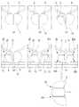
이러한 전립선비대증을 치료하기 위해 도 1에 도시된 전립선비대증 시술방법이 시행된다.In order to treat such an enlarged prostate, the procedure for prostatic hypertrophy shown in FIG. 1 is performed.
전립선비대증이 발생되면 도 1의 (a)에 도시된 바와 같이 요도 양쪽으로 한 쌍의 전립선(A,B)이 비대해져 요도(C)를 막게 된다. 시술자는 도 1의 (b)에 도시된 바와 같이 방광경(10)을 요도 내부로 삽입하고, 도 1의 (c)에 도시된 바와 같이 방광경(10)의 단부로 의료용 결찰기(11)를 전립선(A,B)에 관통시킨 후 도 1의 (d)에 도시된 바와 같이 좌측 전립선(A)의 상부에 제1임플란트(20)를 시술하고, 도 1의 (e)에 도시된 바와 같이 우측 전립선(B)의 상부에 제2임플란트(20a)를 시술한다.When an enlarged prostate occurs, a pair of prostates (A, B) are enlarged to both sides of the urethra as shown in (a) of FIG. 1, thereby blocking the urethra (C). The operator inserts the
그리고 도 1의 (f)에 도시된 바와 같이 좌측 전립선(A)과 우측 전립선(B)의 하부에도 각각 제3임플란트(20b)와 제4임플란트(20c)를 시술한다.And, as shown in (f) of FIG. 1, the
이 때, 각 임플란트(20,20a,20b,20c)는 전립선(A,B)의 외측에 배치되는 외측임플란트(21)와 요도 측에 배치되는 내측임플란트(23)가 결찰사(25)에 의해 연결되고, 결찰사(25)의 길이만큼 내측임플란트(23)가 전립선(A,B)을 외측으로 압박하여 요도가 개방된다.At this time, each of the implants (20, 20a, 20b, 20c) is a lateral implant (21) disposed on the outside of the prostate (A, B) and an inner implant (23) disposed on the urethra side by the ligature thread (25). It is connected, and the
그런데, 이러한 종래 전립선비대증 시술방법은 한 개의 임플란트(20)를 이용해 압박할 수 있는 전립선 조직의 면적이 내측임플란트(23)의 크기로 제한되는 한계가 있다.However, such a conventional prostatic hyperplasia treatment method has a limitation in that the area of the prostate tissue that can be compressed using one
또한, 상부에 배치되는 임플란트(20)와 하부에 배치되는 임플란트(20b) 사이에 이격 간격이 존재하게 되므로, 상부 내측임플란트와 하부 내측임플란트 사이(a)는 압박되지 못하고 여전히 요도 쪽으로 비대해져 있는 상태가 유지되어 압박되는 전립선 조직이 연속되지 못하고 내측임플란트(23)와 접해있는 부분만 부분적으로 압박되는 한계가 있다.In addition, since a separation gap exists between the
본 발명의 목적은 상술한 문제를 해결하기 위한 것으로, 전립선의 상하로 배치되며 서로 결찰사에 의해 연결된 한 쌍의 앵커에 의해 압박면적을 조절할 수 있는 전립선비대증 시술장치를 제공하는 것이다.It is an object of the present invention to solve the above-described problem, and to provide a prostatic hyperplasia treatment apparatus capable of adjusting the compression area by a pair of anchors that are arranged above and below the prostate and connected to each other by a ligator.
본 발명의 다른 목적은 한 쌍의 앵커를 연결하는 결찰사의 길이를 조절하여 환자별 전립선 크기에 따라 전립선을 연속적으로 압박할 수 있는 전립선비대증 시술장치를 제공하는 것이다.Another object of the present invention is to provide a prostatic hyperplasia treatment apparatus capable of continuously compressing the prostate according to the size of the prostate for each patient by adjusting the length of the ligator connecting a pair of anchors.
상술한 본 발명의 목적은 전립선비대증 시술장치에 의해 달성될 수 있다. 본 발명의 전립선비대증 시술장치는, 전립선요도를 압박하는 전립선의 외측에 상하로 배치되는 한 쌍의 앵커(210,220)와, 상기 한 쌍의 앵커(210,220)를 서로 연결하여 상기 한 쌍의 앵커(210,220)가 상기 전립선 조직을 연속적으로 압박하여 전립선요도가 확보되게 하는 결찰실(230)을 갖는 앵커조립체(200)와; 요도로 삽입되며 상기 앵커조립체(200)가 상기 전립선에 결찰되도록 안내하는 니들(350)을 수용하는 쉬스(300)와; 상기 니들(350)이 상기 쉬스(300)의 단부를 통해 배출되도록 상기 니들(350)의 이동을 조작하는 니들조작부(400)를 포함한다.The object of the present invention described above can be achieved by a prostatic hyperplasia treatment apparatus. The apparatus for treating prostatic hyperplasia of the present invention connects a pair of
또한, 상기 니들조작부(400)의 일측에 구비되어 상기 결찰실(230)을 권취하여 상기 앵커조립체(200)가 상기 전립선을 압박하는 강도를 조절하는 실와인더(500)와; 상기 쉬스(300)의 단부와 상기 니들조작부(400) 및 상기 실와인더(500)를 지지하며, 시술자가 파지하는 손잡이프레임부(100)를 포함하는 것이 바람직하다.In addition, a
본 발명에 따른 전립선비대증 시술장치는 종래 전립선의 조직을 부분적으로 압박하던 시술방법과 비교할 때, 결찰실과 한 쌍의 앵커에 의해 압박되는 전립선 조직이 계속 이어져 있으므로 요속이 더욱 빨라질 수 있는 장점이 있으며, 이는 전립선의 길이가 긴 환자들에게 더욱 큰 효과를 나타낼 수 있다.The prostatic hyperplasia treatment apparatus according to the present invention has the advantage that the urinary velocity can be faster because the prostate tissue pressed by the ligation chamber and a pair of anchors continues to be connected as compared with the conventional method of partially compressing the tissue of the prostate. This can have a greater effect on patients with a long prostate.
또한, 본 발명에 따른 전립선비대증 시술장치는 시술자가 결찰실의 자유단을 감아 결찰실의 길이를 조절하여 시술자가 희망하는 만큼 전립선을 압박하는 강도를 조절할 수 있는 장점이 있다.In addition, the prostatic hyperplasia treatment apparatus according to the present invention has the advantage of allowing the operator to adjust the length of the ligation chamber by winding the free end of the ligation chamber, thereby controlling the intensity of compressing the prostate as much as the operator desires.
이에 따라 환자별로 다양한 전립선 비대증 증상에 맞게 압박정도를 조절할 수 있는 효과가 있다.Accordingly, there is an effect that the degree of compression can be adjusted according to various symptoms of enlarged prostate for each patient.
이러한 본 발명의 전립선비대증 시술장치를 이용한 시술방법은 열에너지를 이용한 다른 레이저 시술이나 전기적 수술 같이 전신 마취나 긴 수술시간을 요구하지 않는다.Such a procedure using the apparatus for prostatic hyperplasia of the present invention does not require general anesthesia or long operation time, such as other laser procedures or electrical surgery using thermal energy.
간단한 앵커 설치방법을 통해 빠른 수술 시간과 부분 마취를 가능하게 하며 전립선 조직을 잘라내지 않아서 역행성 사정, 발기 부전 또는 혈뇨와 같은 부작용 을 동반하지 않는다. 또한, 비침습적이므로 효과가 없을 경우 언제든 다른 수술을 추가로 받을 수 있는 장점이 있다.A simple anchor installation method enables quick operation time and partial anesthesia, and does not have side effects such as retrograde ejaculation, erectile dysfunction or hematuria because the prostate tissue is not cut. In addition, since it is non-invasive, it has the advantage of being able to receive additional surgery at any time if there is no effect.
도 1은 종래 전립선비대증 시술방법을 도시한 예시도,
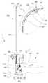
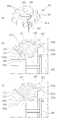
도 2는 본 발명에 따른 전립선비대증 시술장치의 구성을 도시한 사시도,
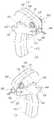
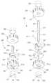
도 3 내지 도 5는 본 발명에 따른 전립선비대증 시술장치의 구성을 분해하여 도시한 분해사시도,
도 6은 본 발명에 따른 전립선비대증 시술장치의 측면구성을 도시한 측면도,
도 7은 본 발명에 따른 전립선비대증 시술장치의 앵커조립체의 구성을 도시한 사시도,
도 8은 본 발명에 따른 전립선비대증 시술장치의 앵커조립체가 좌측 전립선에 결찰된 상태를 도시한 예시도,
도 9는 본 발명에 따른 전립선비대증 시술장치의 니들안내부재의 구성을 도시한 도면,
도 10은 본 발명에 따른 전립선비대증 시술장치의 손잡이프레임부의 외부구성을 도시한 사시도,
도 11은 본 발명에 따른 전립선비대증 시술장치의 니들조작부의 구성을 도시한 사시도,
도 12는 본 발명에 따른 전립선비대증 시술장치의 니들방아쇠의 조작과정을 도시한 예시도,
도 13은 본 발명에 따른 전립선비대증 시술장치의 실와인더의 구성을 도시한 도면,
도 14는 본 발명에 따른 전립선비대증 시술장치의 실와인더의 와인드기어의 동작을 도시한 예시도,
도 15 내지 도 17은 본 발명에 따른 전립선비대증 시술장치의 사용과정을 도시한 예시도들이다.
도 18과 도 19는 본 발명에 따른 전립선비대증 시술장치의 전립선비대증 시술과정을 개략적으로 도시한 예시도이다.1 is an exemplary view showing a conventional prostatic hyperplasia procedure method,
2 is a perspective view showing the configuration of a prostatic hyperplasia treatment apparatus according to the present invention;
3 to 5 are exploded perspective views showing the configuration of the prostatic hyperplasia treatment apparatus according to the present invention,
Figure 6 is a side view showing a side configuration of the prostatic hyperplasia treatment apparatus according to the present invention,
7 is a perspective view showing the configuration of the anchor assembly of the prostatic hyperplasia treatment apparatus according to the present invention;
8 is an exemplary view showing a state in which the anchor assembly of the prostatic hyperplasia treatment apparatus according to the present invention is ligated to the left prostate.
9 is a view showing the configuration of a needle guide member of the prostatic hyperplasia treatment apparatus according to the present invention;
10 is a perspective view showing the external configuration of the handle frame portion of the prostatic hyperplasia treatment apparatus according to the present invention;
11 is a perspective view showing the configuration of a needle operation unit of the prostatic hyperplasia treatment apparatus according to the present invention;
12 is an exemplary view showing an operation process of a needle trigger of the prostatic hyperplasia treatment apparatus according to the present invention;
13 is a view showing the configuration of the thread winder of the prostatic hyperplasia treatment apparatus according to the present invention;
14 is an exemplary view showing the operation of the winding gear of the thread winder of the prostatic hyperplasia treatment apparatus according to the present invention;
15 to 17 are exemplary views showing a process of using the apparatus for treating an enlarged prostate according to the present invention.
18 and 19 are exemplary views schematically showing a prostatic hyperplasia procedure of the prostatic hyperplasia apparatus according to the present invention.
이하에서는 본 발명의 바람직한 실시예 및 첨부하는 도면을 참조하여 본 발명을 상세히 설명하되, 도면의 동일한 참조부호는 동일한 구성요소를 지칭함을 전제하여 설명하기로 한다.Hereinafter, the present invention will be described in detail with reference to a preferred embodiment of the present invention and the accompanying drawings, but it will be described on the premise that the same reference numerals refer to the same elements.
발명의 상세한 설명 또는 특허청구범위에서 어느 하나의 구성요소가 다른 구성요소를 "포함"한다고 할 때, 이는 특별히 반대되는 기재가 없는 한 당해 구성요소만으로 이루어지는 것으로 한정되어 해석되지 아니하며, 다른 구성요소들을 더 포함할 수 있는 것으로 이해되어야 한다.In the detailed description of the invention or in the claims, when any one component "includes" another component, it is not construed as being limited to only the component unless otherwise stated, and other components It is to be understood that it may further include.
도 2는 본 발명에 따른 전립선비대증 시술장치(1)의 구성을 도시한 사시도이고, 도 3 내지 도 5는 전립선비대증 시술장치(1)의 구성을 분해하여 도시한 분해사시도이고, 도 6은 전립선비대증 시술장치(1)의 측면구성을 도시한 측면도이다.2 is a perspective view showing the configuration of the prostatic
본 발명에 따른 전립선비대증 시술장치(1)는 사용자가 손으로 파지하며 각 구성을 고정하는 손잡이프레임부(100)와, 전립선(A,B)에 결찰되어 요도를 막고 있는 전립선조직을 압박하여 요도가 개방되게 하는 앵커조립체(200)와, 손잡이프레임부(100)의 선단으로 일정길이 연장형성되어 요도(C)로 삽입되어 앵커조립체(200)가 전립선(A,B)에 결찰되도록 내부에 수용된 니들(350)을 안내하는 쉬스(300)와, 손잡이프레임부(100)에 구비되어 니들(350)의 위치를 조절하고 앵커조립체(200)가 니들(350) 밖으로 배출되도록 시술자에 의해 조작되는 니들조작부(400)와, 손잡이프레임부(100)에 회전가능하게 구비되어 앵커조립체(200)의 결찰실(230)을 권취하여 앵커조립체(200)가 전립선(A,B)을 압박하도록 결찰실(230)의 길이를 조절하는 실와인더(500)를 포함한다.The prostatic
본 발명에 따른 전립선비대증 시술장치(1)는 한 쌍의 앵커조립체(200)를 이용해 요도를 누르는 전립선조직을 시술자가 원하는 압박강도로 연속적으로 압박할 수 있다. 이에 따라 환자별 전립선비대 증상에 맞게 전립선 압박길이와 압박두께를 조절할 수 있고 요속(velocity of urination)을 빨라지게 할 수 있는 장점이 있다.The prostatic
손잡이프레임부(100)는 도 2 내지 도 4에 도시된 바와 같이 쉬스(300)의 후방에 결합되며, 니들조작부(400)를 수용한다. 손잡이프레임부(100)는 시술자가 손으로 파지한 상태로 쉬스(300)와 니들조작부(400)를 조작하여 쉬스(300)를 요도 내부로 삽입시킨 후 앵커조립체(200)를 전립선에 결찰시키기 위해 니들(350)과 앵커조립체(200)의 위치를 조절할 수 있게 한다.The
손잡이프레임부(100)는 좌우로 배치된 좌측프레임(110)과 우측프레임(120)이 서로 착탈가능하게 결합되어 형성된다. 좌측프레임(110)과 우측프레임(120)은 전체적으로 손으로 파지할 수 있는 손잡이 형태로 형성된다.The
좌측프레임(110)과 우측프레임(120)의 내측 판면에는 니들조작부수용홈(111)이 일정깊이 함몰형성되어 좌측프레임(110)과 우측프레임(120) 사이에 니들조작부(400)의 위치가 고정될 수 있다. 그리고, 니들조작부수용홈(111) 내부에서 니들조작부(400)의 니들홀더(410)가 안정적으로 전후로 이동될 수 있다.A needle operation
니들조작부수용홈(111)의 상부에는 실와인더수용홈(113)이 판면에 대해 일정깊이 함몰형성된다. 실와인더수용홈(113)에는 도 4에 도시된 바와 같이 실와인더(500)의 와인드기어(530)가 수용된다. 실와인더수용홈(113)의 바닥면에는 와인드축(510)이 삽입되는 축결합공(113c)이 관통형성되고, 실와인더수용홈(113)의 외주연에는 와인더고정홈(113a)과 제한바수용홈(113b)이 반경방향 외측으로 연장형성된다.A thread
와인더고정홈(113a)에는 와인드기어(530)의 실가이드캡(537)의 위치고정돌기(537a)가 수용된다. 이에 의해 와인드기어(530)는 실와인더수용홈(113) 내부에서 회전되고, 실가이드캡(537)은 회전되지 않고 위치가 고정된다.The
제한바수용홈(113b)에는 실와인더(500)의 일방향회전제한바(540)가 수용되어 와인드기어(530)가 일방향 회전만 되도록 회전방향을 제한한다.The one-way
와인더고정홈(113a)의 바닥면에는 축결합공(113c)이 관통형성된다. 축결합공(113c)에는 실와인더(500)의 와인드축(510)이 관통삽입된다.A
좌측프레임(110)과 우측프레임(120)은 서로 대향되는 방향에 푸셔이동슬릿(112,121)과, 블레이드버튼이동슬릿(114,123) 및 잠금부재이동홈(115,125)이 각각 형성된다. 도 2에 도시된 바와 같이 푸셔이동슬릿(112,121)과 블레이드버튼이송슬릿(114,123) 및 잠금부재이동홈(115,125)은 각각 좌측프레임(110)와 우측프레임(120)의 외부로 푸셔버튼(366)과 블레이드가압버튼(375) 및 방아쇠잠금부재(440)가 일정 길이 노출한다.The
시술자는 좌측프레임(110)와 우측프레임(120)의 양측으로 일정길이 돌출되게 노출된 푸셔버튼(366)과 방아쇠잠금부재(440)를 손으로 가압하여 전후로 위치를 조절하여 니들(350)의 위치와 앵커조립체(200)의 위치를 간편하게 조절할 수 있고, 블레이드가압버튼(375)을 조작하여 자유단(237)을 커팅할 수 있다.The operator presses the
한편, 좌측프레임(110)과 우측프레임(120)의 전방에는 니들조작부(400)의 니들홀더(410)의 당김레버(413)가 전후로 이동되게 안내하는 레버이동로(116,126)가 형성된다.Meanwhile, in front of the
또한, 좌측프레임(110)과 우측프레임(120)의 후방에는 시술시 전립선 내부를 시술자가 확인할 수 있게 하는 경요도내시경(600)이 삽입되는 내시경삽입공(117,127)이 형성된다.In addition, at the rear of the
앵커조립체(200)는 피시술자의 전립선 외부 표면에 결찰되어 전립선을 압박하여 요도가 개방되게 한다. 본 발명의 전립선비대증 시술장치(1)는 한 쌍의 앵커조립체(200)가 각각 좌측 전립선(A)과 우측 전립선(B)에 결찰되어 시술이 완료된다. 도 7은 하나의 앵커조립체(200)의 구성을 도시한 도면이고, 도 8은 앵커조립체(200)가 좌측 전립선(A)에 시술되어 길이가 조절되기 전 상태를 도시한 예시도이다.The
앵커조립체(200)는 도 7의 (a)에 도시된 바와 같이 제1앵커(210) 및 제2앵커(220)와, 제1앵커(210)와 제2앵커(220)를 서로 연결하는 결찰실(230)을 포함한다. 제1앵커(210)는 내부가 비어있는 중공관 형태로 형성된다. 제1앵커(210)의 표면에는 결찰실(230)이 삽입되는 제1실결합공(211) 및 제2실결합공(213)이 형성된다. 제2실결합공(213)에는 양측으로 일정 길이의 절곡슬릿(215)이 형성된다. 절곡슬릿(215)에 의해 절곡판(217)이 일정각도 경사지게 절곡되며 제2실결합공(213)의 크기를 확장시킨다.The
결찰실(230)은 제1실결합공(211)으로 유입된 후 제2실결합공(213)으로 배출되는데 제1앵커(210)의 관로가 좁으므로 제1실결합공(211)으로 유입된 결찰실(230)을 제2실결합공(213)으로 배출하기가 용이하지 않다. 이를 위해 절곡슬릿(215)을 형성하여 절곡판(217)을 절곡시킨 후 제2실결합공(213)의 크기를 확장하여 결찰실(230)을 용이하게 배출할 수 있게 된다.The ligating
제1앵커(210)와 제2앵커(220)는 금속 또는 금속합금으로 형성된다. 바람직하게는 니티놀로 형성되며 동일한 구성을 갖는다. 제1앵커(210)와 제2앵커(220)는 절곡슬릿(215)에 의해 절곡된 상태이나, 도 16의 (a)에 도시된 바와 같이 니들(350)의 내부에 수용될 때는 니들(350)의 형상에 맞게 탄성 변형된다. 도 16의 (b)에 도시된 바와 같이 니들(350) 밖으로 배출되면 앵커(210,220)의 절곡판(217, 227)은 원래 되로 절곡된 상태로 복귀된다.The
절곡슬릿(215)에 의해 절곡판(217)은 제1앵커(210)의 외표면에 대해 절곡되면서 전립선 조직을 뚫고 전립선 외측 표면에 위치된 제1앵커(210)가 니들(350)에 의해 형성된 전립선의 관통공으로 다시 역이동되는 것을 방지한다.The
즉, 시술과정에서 니들(350)이 전립선(A,B)을 뚫고 전립선(A,B)의 외측으로 제1앵커(210)를 배출하면, 제1앵커(210)는 탄성적으로 절곡판(217)이 휘어지며 절곡된다. 이러한 절곡된 제1앵커(210)는 니들(350)에 의해 형성된 관통공에 걸려 역방향 이동되는 것이 방지되어, 전립선(A) 표면에 안정적으로 안착될 수 있다.That is, when the
결찰실(230)은 제1앵커(210)와 제2앵커(220)를 길이조절이 가능하게 서로 연결하며 제1앵커(210)와 제2앵커(220)가 각각 독립적으로 전립선의 특정 부분을 압박하는 형태가 아니라 제1앵커(210)와 제2앵커(220) 및 결찰실(230)에 의해 이어진 원호 또는 "ㄷ"자 형상의 라인이 연속적으로 전립선 조직을 압박하게 한다.The
결찰실(230)은 도 7의 (b)에 도시된 바와 같이 제1앵커(210)에 결합되는 고정단(231)과, 제2앵커(220)에 결합되는 길이조절루프(233)와, 길이조절루프(233)의 단부에 연결되는 자유단(237)과, 자유단(237)과 길이조절루프(233)을 묶는 슬립매듭(235)을 포함한다.The
고정단(231)은 제1앵커(210)의 제1실결합공(211)과 제2실결합공(213)에 묶여 위치가 고정되고, 길이조절루프(233)는 제2앵커(220)의 제1실결합공(221)으로 유입된 후 제2앵커(220)의 제2실결합공(223)으로 배출되어 루프형태로 형성된다. 길이조절루프(233)는 고정단(231)과 자유단(237) 사이에 슬립매듭(235)에 의해 형성된다.The
도 7의 (c)에 도시된 바와 같이 자유단(237)을 당기면 고정단(231)에 결합된 제1앵커(210)의 위치가 고정되어 있으므로 길이조절루프(233)의 길이가 짧아지게 되고, 이들이 감싸고 있는 전립선 조직을 압박하게 된다.When the
도 8에 도시된 바와 같이 제1앵커(210)와 제2앵커(220)가 전립선(A,B)의 외측에 배치되면 결찰실(230)이 헐겁게 배치된다. 이 상태에서 시술자가 와인드손잡이(520)를 회전시켜 자유단(237)을 와인드기어(530)에 권취하면 자유단(237)의 길이가 짧아지며 길이조절루프(233)가 짧아지며 전립선(A,B)을 압박하게 된다.As shown in FIG. 8, when the
즉, 도 19의 (b)에 도시된 바와 같이 제1앵커(210)와 제2앵커(220)가 전립선의 외측에 배치되면 결찰실(230)이 느슨하게 연결된다. 시술자가 와인드손잡이(520)를 이용해 자유단(237)을 당긴 후 결찰실(230)을 팽팽하게 조이면 도 19의 (c)에 도시된 바와 같이 제1앵커(210)와 제2앵커(220) 및 결찰실(230)이 전립선(A,B)을 연속적으로 감싸며 압박하게 된다. 결찰실(230)에 의해 제1앵커(210)와 제2앵커(220)가 연결되어 있으므로 제1앵커(210)와 제2앵커(220) 사이의 공간도 연속적으로 압박되며 요도(C)가 개방되게 된다.That is, as shown in (b) of FIG. 19, when the
쉬스(300)는 니들(350)을 통해 앵커조립체(200)를 전립선(A,B)으로 안내하여 앵커조립체(200)의 위치를 고정한다. 도 5와 도 6에 도시된 바와 같이 쉬스(300)의 후단은 손잡이프레임부(100)에 결합되고 선단은 손잡이프레임부(100)로부터 일정길이 연장되며 아우터쉬스(S)를 통해 요도(C) 내부로 삽입된다.The
도 18과 도 19에 도시된 바와 같이 시술자는 아우터쉬스(S)를 통해 요도(C) 내부로 삽입된 쉬스(300) 내부로 경요도내시경(600)을 삽입하여 전립선 내부를 확인하며 니들(350)이 전립선(A,B)을 뚫고 나가 한 쌍의 앵커(210,220)가 전립선(A,B)의 외측에 배치되게 조작한다.18 and 19, the operator inserts the
쉬스(300)는 일정 길이를 갖는 관 형태로 구비되며 니들삽입관(310)과 내시경삽입관(320) 및 블레이드이동축(330)이 일체로 결합되어 형성된 쉬스본체(300a)와, 쉬스본체(300a)의 선단에 구비되어 니들(350)을 전립선(A,B) 측으로 안내하는 니들안내부재(340)와, 니들삽입관(310) 내에 수용되며 앵커조립체(200)를 전립선(A,B)으로 안내하는 니들(350)과, 니들(350) 내부에 앵커조립체(200)의 후단에 삽입되어 앵커조립체(200)를 니들 선단으로 가압하는 푸셔(360)와, 니들안내부재(340)의 하부에 전후 이동가능하게 구비되어 결찰실(230)을 절단하는 니들블레이드부(370)와, 쉬스(300)를 손잡이프레임부(100)에 결합시키는 쉬스고정부재(380)를 포함한다.The
니들삽입관(310)은 니들(350)이 수용되고, 내시경삽입관(320)은 니들삽입관(310)의 하부에 일체로 구비되어 내시경(600)이 이동되는 통로를 제공하며, 블레이드축이동관(330)은 내시경삽입관(320)의 하부에 일체로 결합되어 블레이드판연결축(373)이 이동되는 통로를 제공한다.The
쉬스본체(300a)는 각각 관 형태로 형성된 니들삽입관(310)과 내시경삽입관(320) 및 블레이드축이동관(330)이 도 4에 확대도시된 바와 같이 상하로 일체로 결합된어 형성된다. 쉬스본체(300a)는 니들홀더(410)의 쉬스삽입공(411c)에 후단이 삽입된다. 이 때, 도 5에 도시된 바와 같이 내시경삽입관(320)은 니들삽입관(310) 및 블레이드축이동관(330) 보다 길게 형성되며, 내시경삽입관(320)의 단부(320a)는 니들홀더(410)의 외측에 배치된다.The sheath body (300a) is formed by integrally coupled up and down as shown in the enlarged view of Figure 4, the
그리고 내시경삽입관(320)의 단부(320a)로 도 6에 도시된 바와 같이 경요도내시경(600)이 삽입되고, 경요도내시경입구(610)가 단부(320a)에 배치된다.And the
니들삽입관(310)은 후단을 통해 니들(350)이 삽입되고, 후단을 통해 푸셔(360)가 결합된다. 니들삽입관(310)과 블레이드축이동관(330)의 선단에는 니들안내부재(340)가 착탈가능하게 결합된다.The
여기서, 쉬스(300)의 각 부품들과 손잡이프레임부(100) 및 앵커조립체(200), 니들조작부(400) 및 실와인더(500)는 제조사에서 도 1에 도시된 바와 같이 완전 조립된 형태로 조립된 후 멸균포장되어 병원으로 제공된다. 이에 따라 시술자가 각 부품을 분해하거나 조립할 필요가 없이 시술시에 조립된 상태 그대로 사용하면 되므로 사용편의성이 향상될 수 있다.Here, each of the parts of the
도 9는 쉬스(300)의 선단 구조를 도시한 도면이다. 도 9의 (a)에 도시된 바와 같이 니들안내부재(340)는 안내본체(341)와, 안내본체(341)의 후방으로 돌출되어 니들삽입관(310)에 결합되는 니들삽입관연결관(342)과, 블레이드축이동관(330)에 결합되는 블레이드축연결관(345)을 포함한다.9 is a view showing the front end structure of the
니들안내부재(340)는 니들삽입관연결관(342)과 블레이드축연결관(345)이 니들삽입관(310)과 블레이드축이동관(330)에 결합되어 위치가 고정된다. 니들삽입관연결관(342)과 블레이드축연결관(345) 사이에는 니들(350)을 외부로 노출하는 니들노출공(344)이 형성된다. 니들노출공(344)을 통해 내시경삽입관(320)으로 이동된 경요도내시경(600)이 요도(C) 내부로 노출될 수 있다.In the
또한, 니들노출공(344)을 통해 니들(350)에 수용되어 있던 결찰실(230)이 외부로 노출되며 간섭없이 결찰실(230)이 전립선(A,B)으로 이동될 수 있게 한다.In addition, the
블레이드축연결관(345)의 상부에는 니들(350)을 외부로 배출하는 니들배출구(346)가 형성된다. 니들배출구(346)에는 니들블레이드부(370)의 블레이드판(371)이 슬라이딩 이동가능하게 결합된다.A
니들노출공(344)을 형성하는 상부측 내벽에는 니들(350)을 요도(C)로 안내하는 니들안내곡면(343)이 형성된다. 니들(350)은 초기상태에서 니들삽입관(310) 내부에 도 9의 (b)에 도시된 바와 같이 배치되고, 시술자가 니들방아쇠(420)를 조작하면 도 9의 (a)에 도시된 바와 같이 니들안내부재(340)를 통해 외부로 일정길이 노출된다.A needle guide curved
이 때, 니들(350)은 니들안내곡면(343)의 곡면을 따라 일정각도 휘어지며 전립선(A,B)을 뚫고 이동된다.At this time, the
니들(350)은 일정 길이를 갖도록 형성되며, 니들삽입관(310) 내에 삽입된 상태에서 시술자의 니들방아쇠(420) 조작에 의해 니들안내부재(340)를 통해 전립선(A,B) 내부로 안내된다.The
니들(350)은 금속이나 금속합금으로 만들어질 수 있으며, 바람직하게 니티놀로 만들어진다. 니들(350)은 선단이 휘어진 형태로 제조되며, 니들삽입관(310)에 수용되어 있을 때는 니들안내곡면(420)에 위치되어 니들안내곡면(420)의 곡률에 대응되게 탄성적으로 휘어진 형태를 유지한다. 니들방아쇠(420)에 의해 발사되어 니들안내부재(340)를 통해 전립선(A,B) 내부로 배출되면 니들안내곡면(343)에 의해 배출각도가 조절되고, 제조시 형성된 곡률에 맞게 휘어진다.The
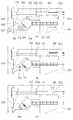
니들배출구(346)로 배출되는 니들(350)의 선단에는 도 6에 확대 도시된 바와 같이 앵커조립체(200)의 결찰실(230)을 외부로 노출시키는 니들슬롯(351)이 형성된다. 니들슬롯(351)의 길이는 제1앵커(210)와 제2앵커(220)의 길이를 합한 길이 또는 그 보다 짧게 설계된다. 일례로, 제1앵커(210)와 제2앵커(220)의 길이가 각각 8mm일 때, 니들슬롯(351)의 길이를 16mm로 형성되고, 니들슬롯(351)의 폭은 0.4mm로 형성될 수 있다. 이 때, 니들슬롯(351)의 폭은 선단에서 내측으로 갈수록 좁아지게 형성될 수 있다.A
푸셔(360)는 니들(350)의 후단에 배치되어 니들(350)이 전립선(A,B) 조직을 뚫고 삽입되었을 때, 제1앵커(210)와 제2앵커(220)를 순차적으로 밀어 제1앵커(210)와 제2앵커(220)가 니들(350) 밖으로 배출되게 한다.The
푸셔(360)는 도 5에 도시된 바와 같이 니들(350) 내부로 삽입되는 푸셔축(361)과, 푸셔축(361)의 후단에 일정길이 형성되어 니들홀더(410)에 삽입되는 푸셔홀더(363)와, 푸셔축(361)의 후단에 직교하게 연장형성되는 푸셔버튼축(365)과, 푸셔버튼축(365)의 단부에 일정면적 형성되어 시술자에 의해 조작되는 푸셔버튼(366)과, 푸셔축(361)의 선단에 상부로 돌출되게 형성되어 푸셔축(361)의 위치를 고정하는 푸셔테일(367)을 포함한다.The
푸셔축(361)은 니들(350)의 내부로 삽입되어 도 6에 확대도시된 바와 같이 제2앵커(220)의 후단에 위치된다. 푸셔축(361)은 시술자가 푸셔버튼(366)을 이용해 위치를 전방으로 이동시키면 제2앵커(220)를 밀어 제1앵커(210), 제2앵커(220)가 니들(350) 밖으로 배출되게 한다.The
푸셔홀더(363)는 니들홀더(410)의 수평바(411)와 상부결합바(415) 사이에 수용된다. 푸셔홀더(363)는 푸셔축(361)의 후단에 일정 길이 연장형성되어 푸셔축(361)이 전후로 이동될 수 있게 지지한다.The
푸셔버튼축(365)은 푸셔축(361)과 푸셔홀더(363)의 경계영역에 좌우방향으로 좌측프레임(110)과 우측프레임(120)의 푸셔이동슬릿(112,121)까지 연장형성된다. 푸셔버튼(366)은 좌우측푸셔이동슬릿(112,121) 외부로 노출된 푸셔버튼축(365)의 단부에 결합된다.The
시술자는 도 2에 도시된 바와 같이 손잡이프레임부(100)의 푸셔이동슬릿(112,121) 외부로 노출된 푸셔버튼(366)을 전후로 가압하여 푸셔축(361)의 위치를 조절할 수 있다.As shown in FIG. 2, the operator may adjust the position of the
도 10의 (a)에 도시된 바와 같이 푸셔이동슬릿(112,121)의 제일 후단에 푸셔버튼(366)이 위치되면 푸셔축(361)이 뒤로 밀려난 상태이고, 제1앵커(210)와 제2앵커(220) 모두 도 16의 (a)에 도시된 바와 같이 니들(350) 내부에 수용된다.10(a), when the
도 15의 (c)에 도시된 바와 같이 시술자가 푸셔버튼(366)을 전방으로 밀어 이동시키면, 푸셔축(361)이 제2앵커(220)를 이동거리만큼 가압하여 도 16의 (b)에 도시된 바와 같이 제1앵커(210)를 니들(350) 밖으로 배출시킨다.As shown in (c) of FIG. 15, when the operator pushes the
여기서, 푸셔테일(367)은 시술자가 푸셔버튼(366)을 이동시키는 거리를 앵커(210,220)의 길이만큼으로 제한하게 한다.Here, the
도 11의 (b)는 니들홀더(410)와 푸셔(360)의 결합구조를 도시한 사시도이다. 니들홀더(410)의 상부결합바(415)의 내부에는 상면에 테일위치고정레일(416)이 니들슬롯(351)의 길이에 대응되게 형성된다. 그리고, 각 앵커(210,220)의 길이에 대응되는 간격으로 제1홈(416a), 제2홈(416b) 및 제3홈(416c)이 상부로 함몰되게 형성된다.11 (b) is a perspective view showing a coupling structure between the
푸셔테일(367)은 시술자가 푸셔버튼(366)을 이동시킬 때, 제1홈(416a), 제2홈(416b) 및 제3홈(416c)에 순차적으로 걸림결합되며 푸셔축(361)의 이동거리를 앵커(210,220)의 길이로 제한한다.The
이에 의해 제1홈(416a)에 걸려있을 때 제1앵커(210)와 제2앵커(220) 모두 니들(350) 내부에 수용되고, 시술자가 푸셔버튼(366)을 가압하여 푸셔테일(367)이 제2홈(416b)에 위치되도록 푸셔축(361)이 전방으로 이동되면, 제1앵커(210)가 니들(350) 밖으로 배출된다. 그리고 시술자가 제2홈(416b)에 위치된 푸셔테일(367)이 제3홈(416c)에 위치되도록 푸셔축(361)을 전방으로 이동시키면 도 17에 도시된 바와 같이 푸셔축(361)이 니들(350) 선단까지 이동되고 제2앵커(220)는 니들(350) 밖으로 배출된다.Accordingly, when both of the
니들블레이드부(370)는 니들(350) 밖으로 제1앵커(210)와 제2앵커(220)가 배출되고 각각 전립선(A,B)의 외측면에 배치될 때, 길이조절이 완료된 결찰실(230)의 자유단(237)을 끊는 역할을 한다.When the
니들블레이드부(370)는 도 5에 도시된 바와 같이 니들안내부재(340)의 니들배출구(346)에 슬라이딩 이동가능하게 결합되는 블레이드판(371)과, 블레이드판(371)으로부터 손잡이프레임부(100)까지 연장형성되는 블레이드판연결축(373)과, 블레이드판연결축(373)의 후단에 구비되는 블레이드가압버튼(375)을 포함한다.The
블레이드판(371)은 니들배출구(346)에 구비되어 블레이드판연결축(373)에 의해 전후로 이동되며 결찰실(230)의 자유단(237)을 끊는다.The
도 19의 (b)에 도시된 바와 같이 니들(350)로부터 배출된 제1앵커(210)와 제2앵커(220)가 각각 전립선(A,B)의 외측표면에 위치되면 결찰실(230)의 자유단(237)은 니들삽입관(310)을 통해 손잡이프레임부(100)의 실와인더(500)에 연결된다. 자유단(237)은 니들삽입관(310)의 내부에 니들(350)과의 사이 공간을 통해 연장되어 실와인더(500)에 연결된다.As shown in (b) of FIG. 19, when the
시술자는 실와인더(500)의 와인드손잡이(520)를 회전시켜 자유단(237)을 감아 전립선(A,B)을 감싸는 결찰실(230)의 길이조절루프(233)의 길이를 팽팽하게 조절한다. 이 때, 블레이드판(371)이 이동되며 길이조절이 완료된 결찰실(230)을 끊게 된다.The operator rotates the winding
블레이드판(371)은 도 5에 확대 도시된 바와 같이 니들배출구(346)에 슬라이딩 이동가능한 면적을 갖는 판 형태로 구비된다. 블레이드판(371)의 내부에는 니들(350)을 배출시키는 니들배출공(371a)이 관통형성된다. 그리고, 니들배출공(371a)의 상부에는 블레이드슬릿(371b)이 형성된다.The
블레이드슬릿(371b)은 점차 폭이 좁아지게 형성되며, 마주보는 내측 단부가 날카롭게 형성된다.The
도 9의 (b)에 도시된 바와 같이 시술자가 블레이드판연결축(373)을 후방으로 당기면 블레이드판(371)이 후방으로 슬라이딩 이동되며 결찰실(230)이 블레이드슬릿(371b) 사이에 끼여지게 된다. 이 과정에서 좁고 날카로운 블레이드슬릿(371b)과 결찰실(230)이 맞닿으며 결찰실(230)의 자유단(237)이 절단된다.As shown in (b) of FIG. 9, when the operator pulls the blade
블레이드판연결축(373)은 쉬스(300)의 블레이드축이동관(330) 내부를 통해 손잡이프레임부(100)의 블레이드버튼이동슬릿(114,123)까지 연장된다. 블레이드판연결축(373)은 시술자가 블레이드가압버튼(375)을 전후로 이동시키는 것을 블레이드판(371)으로 전달한다.The blade
블레이드가압버튼(375)은 손잡이프레임부(100)의 좌우측블레이드버튼이동슬릿(114,123) 외부로 돌출되게 구비되어 시술자에 의해 전후로 이동된다.The blade
앵커(210,220)가 니들(350) 외부로 배출되기 전에는 블레이드가압버튼(375)은 도 2에 도시된 바와 같이 블레이드버튼이동슬릿(114,123)의 전방에 위치된다. 반면, 제1앵커(210)와 제2앵커(220)가 모두 전립선(A,B)에 위치되고 결찰실(230)의 자유단(237)을 끊어야할 때는 시술자에 의해 블레이드가압버튼(375)은 도 10의 (a)에 도시된 바와 같이 블레이드버튼이동슬릿(114,123)의 후방으로 이동된다.Before the
이에 의해 도 9의 (b)에 도시된 바와 같이 블레이드판(371)이 후방으로 당겨지며 결찰실(230)을 끊게 된다.As a result, as shown in (b) of FIG. 9, the
블레이드판(371)은 니들안내부재(340) 내부에 수용된 상태로 준비되고, 블레이드판연결축(373)은 블레이드가압버튼(375)에 연결된 상태로 손잡이프레임부(100)에 결합되어 준비된다.The
쉬스고정부재(380)는 쉬스(300)를 손잡이프레임부(100)에 결합시킨다. 쉬스고정부재(380)는 도 4에 도시된 바와 같이 손잡이프레임부(100)의 쉬스결합판삽입홈(119)에 끼움결합되는 쉬스결합판(381)과, 내부에 쉬스(300)가 삽입되는 쉬스결합관(383)과, 쉬스결합관(383)과 쉬스결합판(381) 사이에 고정되는 고정링(385)을 포함한다.The
쉬스결합판(381)은 손잡이프레임부(100)의 쉬스결합판삽입홈(119)에 끼워져 위치가 고정된다. 쉬스결합판(381)의 전방에는 복수개의 결합돌기(381a)가 형성된다. 쉬스결합관(383)은 내부로 쉬스(300)가 삽입된다. 쉬스결합관(383)의 배면에는 결합돌기(381a)가 삽입되는 돌기삽입공(미도시)이 형성된다.The
쉬스(300)는 쉬스결합관(383)과 쉬스결합판(381)을 순차적으로 관통하여 니들홀더(410)의 쉬스삽입공(411c)에 삽입된다. 쉬스결합관(383)은 쉬스결합판(381)의 결합돌기(381a)에 끼워져 위치가 고정된다.The
고정링(385)은 쉬스결합관(383)과 쉬스결합판(381)의 사이에 고정된다. 고정링(385)은 시술시에 도 18에 도시된 바와 같이 쉬스본체(300a) 외부에 아우터쉬스(S)를 고정하기 위해 사용된다.The fixing
고정링(385)의 걸림후크(385a)에 아우터쉬스(S)가 걸립결합되어 쉬스본체(300a)의 외부에 아우터쉬스(S)가 고정된다.The outer sheath (S) is engaged with the locking hook (385a) of the fixing ring (385) and the outer sheath (S) is fixed to the outside of the sheath body (300a).
니들조작부(400)는 니들(350)이 쉬스(300)의 외부로 배출되고, 앵커조립체(200)가 니들(350)로부터 배출되어 전립선(A,B)에 배치되도록 니들(350)과 앵커조립체(200)의 위치가 단계적으로 조작되게 한다.The
니들조작부(400)는 도 4와 도 5에 도시된 바와 같이 니들(350)의 위치를 조절하는 니들홀더(410)와, 니들홀더(410)를 탄성적으로 발사시켜 니들(350)이 니들안내부재(340) 밖으로 배출되게 하는 니들방아쇠(420)와, 니들방아쇠(420)의 조작에 의해 니들홀더(410)가 발사될 수 있도록 탄성력을 제공하는 홀더탄성지지부(430)와, 니들방아쇠(420)의 위치를 잠금하는 방아쇠잠금부재(440)를 포함한다.The
니들홀더(410)는 니들방아쇠(420)와 홀더탄성지지부(430)에 의해 앞으로 이동되며 니들(350)이 니들안내부재(340) 밖으로 배출되며 전립선(A,B)을 뚫고 나갈 수 있게 한다. 니들홀더(410)는 수평하게 형성된 수평바(411)와, 수평바(411)의 선단에서 하부로 일정길이 연장형성되어 시술자에 의해 가압되는 당김레버(413)와, 니들(350)이 고정된 상태로 수평바(411)의 상부에 결합되는 상부결합바(415)를 포함한다.The
수평바(411)는 내부에 쉬스(300)의 내시경삽입관(320)이 수용된다. 수평바(411)의 하부에는 길이방향을 따라 홀더위치조절이빨(411a)이 형성된다. 홀더위치조절이빨(411a)은 니들방아쇠(420)의 홀더위치고정이빨(421a)과 맞물려 손잡이프레임부(100) 내부에서 니들홀더(410)의 위치가 조절되게 한다.The
수평바(411)의 상부에는 푸셔버튼이동레일(411b)이 일정길이 형성되고, 수평바(411)의 전방에는 쉬스(300)가 삽입되는 쉬스삽입공(411c)이 형성된다.A pusher
당김레버(413)는 수평바(411)로부터 일정길이 하부로 연장되어, 도 2에 도시된 바와 같이 손잡이프레임부(100)의 외부로 노출된다. 시술자는 외부로 노출된 당김레버(413)를 손으로 당겨 니들방아쇠(420)의 조작에 의해 전방으로 이동된 니들홀더(410)가 후방으로 복귀될 수 있게 위치를 조절한다.The
당김레버(413)의 전방에는 도 4에 도시된 바와 같이 홀더탄성지지부(430)의 탄성부재지지축(431)이 삽입되는 지지축삽입공(413a)이 형성된다. 이에 의해 당김레버(413)가 탄성부재지지축(431)을 따라 전후로 이동하게 된다.In front of the
상부결합바(415)는 수평바(411)의 상부에 결합되어 푸셔버튼이동레일(411b)을 형성한다. 푸셔버튼이동레일(411b)은 손잡이프레임부(100)의 좌우측푸셔이동슬릿(112,121)에 대응되는 위치에 형성되며, 내부에 푸셔버튼축(365)이 이동가능하게 수용된다.The
상부결합바(415)의 내부에는 앞서 설명한 테일위치고정레일(416)이 형성되어 푸셔(360)의 이동거리를 조절한다.The tail
니들방아쇠(420)는 니들홀더(410)를 고정하거나, 니들홀더(410)와의 고정상태를 해제하여 니들홀더(410)가 홀더탄성지지부(430)의 탄성력에 의해 전방으로 발사될 수 있게 한다.The
니들방아쇠(420)는 도 5와 도 12에 도시된 바와 같이 니들홀더(410)와 착탈되는 홀더착탈바(421)와, 홀더착탈바(421)의 하부에 경사지게 형성된 프레임지지바(425)와, 손잡이프레임부(100)에 니들방아쇠(420)가 회동될 수 있게 결합되는 방아쇠회동축(423)과 홀더착탈바(421)가 니들홀더(410)에 결합되는 방향으로 방아쇠회동축(423)이 회동되도록 탄성력을 작용하는 방아쇠복귀스프링(426)을 포함한다.The
홀더착탈바(421)는 방아쇠회동축(423)을 중심으로 니들홀더(410)의 수평바(411)에 나란하게 형성되며, 선단의 상면에 홀더위치고정이빨(421a)이 형성된다. 홀더위치고정이빨(421a)은 도 12의 (a)에 도시된 바와 같이 니들홀더(410)의 홀더위치조절이빨(411a)에 맞물려 니들홀더(410)의 위치를 고정한다.The holder
도 12의 (b)에 도시된 바와 같이 니들방아쇠(420)가 방아쇠회동축(423)을 중심으로 회동되면 홀더착탈바(421)의 홀더위치고정이빨(421a)이 홀더위치조절이빨(411a)로부터 이격되며 니들홀더(410)와의 결합상태가 해제된다. 이에 의해 니들홀더(410)가 홀더탄성지지부(430)의 탄성부재(433)의 탄성력에 의해 전방으로 발사되며 위치가 이동된다.As shown in (b) of FIG. 12, when the
프레임지지바(425)는 방아쇠복귀스프링(426)과 결합되어 방아쇠복귀스프링(426)의 탄성력이 방아쇠회동축(423)과 홀더착탈바(421)로 전달되게 한다. 방아쇠복귀스프링(426)은 일단은 프레임지지바(425)에 고정되고 타단은 프레임고정부재(426a)에 결합된다.The
방아쇠복귀스프링(426)은 홀더착탈바(421)가 니들홀더(410)와 고정되는 방향으로 방아쇠회동축(423)이 회동되도록 탄성력을 작용한다.The
프레임지지바(425)의 후단에는 방아쇠조작버튼(427)이 일정면적 형성된다. 방아쇠조작버튼(427)은 도 2에 도시된 바와 같이 손잡이프레임부(100)의 후단 외측으로 노출되어 시술자에 의해 가압된다. 시술자가 방아쇠조작버튼(427)을 상방향으로 가압하는 동작에 의해 도 12의 (b)에 도시된 바와 같이 홀더착탈바(421)가 회동되며 홀더위치고정이빨(421a)이 홀더위치조절이빨(411a)로부터 이격되고 니들홀더(410)가 전방으로 이동된다.A
프레임지지바(425)와 방아쇠조작버튼(427) 사이에는 잠금축수용고리(429)가 형성된다. 잠금축수용고리(429)는 일단이 개방된 고리 형태로 형성되며 내부에 방아쇠잠금부재(440)가 수용된다.A locking
도 12의 (a)에 도시된 바와 같이 잠금축수용고리(429)에 방아쇠잠금부재(440)가 수용되면, 니들방아쇠(420)의 회동은 제한된다. 이에 의해 니들홀더(410)의 위치도 고정된 상태를 유지하게 된다.As shown in Figure 12 (a), when the
반면, 도 12의 (b)에 도시된 바와 같이 잠금축수용고리(429)로부터 방아쇠잠금부재(440)가 이탈되면 시술자가 방아쇠조작버튼(427)을 조작하여 니들방아쇠(420)를 회동시킬 수 있다.On the other hand, as shown in (b) of FIG. 12, when the
방아쇠잠금부재(440)는 손잡이프레임부(100)의 잠금부재이동홈(115,125)을 따라 좌우로 이동가능하게 구비된다. 이 때, 잠금부재이동홈(115,125)의 후방측 위치가 니들방아쇠(420)의 잠금축수용고리(429)의 위치에 대응되게 형성된다.The
이에 따라 도 15의 (b)에 도시된 바와 같이 잠금부재이동홈(115,125)의 후방에 방아쇠잠금부재(440)가 위치되면 동시에 잠금축수용고리(429)에 수용된다. 반면, 도 15의 (a)에 도시된 바와 같이 잠금부재이동홈(115,125)의 전방으로 방아쇠잠금부재(440)가 위치되면 방아쇠잠금부재(440)는 잠금축수용고리(429)로부터 벗어나게 된다.Accordingly, when the
홀더탄성지지부(430)는 니들홀더(410)가 후방에서 전방으로 빠른 속도로 발사되게 하여 니들삽입관(310) 내부에 수용된 니들(350)이 니들안내부재(340)의 니들배출구(346)로 배출되며 전립선(A,B)을 뚫고 지나갈 수 있는 동력을 제공한다.The holder
홀더탄성지지부(430)는 도 11에 도시된 바와 같이 당김레버(413)에 가로방향으로 결합된 탄성부재지지축(431)과, 탄성부재지지축(431)에 결합된 탄성부재(433)를 포함한다. 탄성부재지지축(431)의 일단은 당김레버(413)의 지지축삽입공(413a)에 수용되고, 탄성부재지지축(431)의 타단에는 손잡이프레임부(100)에 고정되는 축위치고정판(431a)이 구비된다.The holder
탄성부재(433)는 당김레버(413)와 축위치고정판(431a) 사이에 구비되어 니들홀더(410)가 전후로 이동될 수 있게 탄성력을 제공한다.The
도 12의 (a)에 도시된 바와 같이 시술자가 당김레버(413)를 후방으로 당기고 니들방아쇠(420)의 홀더착탈바(421)의 홀더위치고정이빨(421a)을 홀더위치조절이빨(411a)의 전방에 결합시키면 탄성부재(433)는 당김레버(413)와 축위치고정판(431a) 사이에서 압축된다.As shown in Figure 12 (a), the operator pulls the
도 12의 (b)에 도시된 바와 같이 방아쇠잠금부재(440)를 잠금축수용고리(429)로부터 이동시키면 홀더위치고정이빨(421a)이 홀더위치조절이빨(411a)로부터 벗어나고, 탄성부재(433)가 초기 위치로 복귀하기 위해 탄성력을 작용하여 니들홀더(410)가 탄성부재지지축(431)을 따라 전방으로 이동하게 된다.As shown in (b) of FIG. 12, when the
니들홀더(410)가 전방으로 이동하는 속도에 의해 니들삽입관(310) 내부의 니들(350)이 도 6에 도시된 바와 같이 니들안내부재(340)의 니들배출구(346)로 배출되며 전립선(A,B)을 뚫고 삽입된다.By the speed of the
이 때, 탄성부재(433)의 탄성력에 의해 니들(350)이 니들안내부재(340)의 니들배출구(346)로 배출되는 길이는 요도(C)를 중심으로 한 쪽 전립선(A,B)의 조직을 관통하여 외측표면으로 뚫고 나아갈 수 있는 길이로 설정된다.At this time, the length at which the
실와인더(500)는 니들삽입관(310)을 통해 손잡이프레임부(100)까지 연장된 결찰실(230)의 자유단(237)을 감아 길이조절루프(233)의 길이를 조절하여 앵커조립체(200)가 전립선(A,B)을 압박하는 강도를 조절한다.The
실와인더(500)는 도 4에 도시된 바와 같이 손잡이프레임부(100)의 실와인더수용홈(113)의 내외측에 결합된다.The
도 13은 실와인더(500)의 구성을 도시한 사시도이고, 도 14는 실와인더(500)의 동작과정을 도시한 예시도이다.13 is a perspective view showing the configuration of the
도시된 바와 같이 실와인더(500)는 와인드축(510)과, 와인드축(510)의 일측에 결합되어 시술자에 의해 회전조작되는 와인드손잡이(520)와, 와인드축(510)의 타측에 결합되어 와인드축(510)과 함께 회전되며 외주면에 자유단(237)이 권취되는 와인드기어(530)와, 와인드기어(530)의 외표면을 덮으며 와인드기어(530)로 자유단(237)을 안내하는 실가이드캡(537)과, 와인드기어(530)가 일방향 회전만 가능하도록 회전방향을 제한하는 일방향회전제한바(540)와, 와인드손잡이(520)에 결합되는 와인드손잡이커버(550)를 포함한다.As shown, the
와인드축(510)은 도 10의 (a)와 (b)에 도시된 바와 같이 손잡이프레임부(100)의 내부에서 외부로 관통하여 결합되어 와인드손잡이(520)에 의해 회전된다. 와인드축(510)은 와인드손잡이(520)와 와인드기어(530)에 고정결합되어 시술자가 와인드손잡이(520)를 회전조작하면, 손잡이프레임부(100) 내부에 수용된 와인드기어(530)가 함께 회전되게 한다.The
와인드축(510)에는 도 13의 (b)에 도시된 바와 같이 하단과 상단에 각각 제1홀더바(511) 및 제2홀더바(513)가 결합된다. 제1홀더바(511)와 제2홀더바(513)는 수평방향으로 와인드축(510)에 결합된다. 제1홀더바(511)는 와인드손잡이(520)의 홀더결합휠(521)의 홀더결합홈(523)에 끼워진다.A
제1홀더바(511)가 홀더결합휠(521)에 결합되어 와인드손잡이(520)의 회전조작이 와인드축(510)으로 전달되게 된다.The
제2홀더바(513)에는 제1홀더바(511)와 동일하게 와인드손잡이(520)와 와인드손잡이커버(550)가 결합된다. 시술자는 편의에 따라 손잡이프레임부(100)의 양쪽에 구비된 한 쌍의 와인드손잡이(520) 중 편리한 쪽의 와인드손잡이(520)를 조작하여 자유단(237)의 길이를 조절한다.The
와인드축(510)의 경로상에는 돌출된 키(515)가 구비된다. 키(515)는 와인드기어(530)의 축삽입공(535)에 형성된 키홈(535a)에 끼워진다. 이에 의해 와인드축(510)의 회전이 와인드기어(530)로 전달된다.A protruding
와인드손잡이(520)는 도 10의 (b)에 도시된 바와 같이 우측프레임(120)의 외부에 결합되어 시술자가 회전조작한다. 와인드손잡이(520)의 외측에는 홀더결합휠(521)이 돌출되게 구비된다. 홀더결합휠(521)의 표면에는 홀더결합휠(521)과 와인드손잡이커버(550)를 고정시키는 체결부재(미도시)가 삽입되는 내부체결부재삽입공(521a)이 형성된다. 체결부재(미도시)는 와인드손잡이커버(550)의 외부체결부재삽입공(551)을 통해 내부체결부재삽입공(521a)에 삽입되어 와인드손잡이커버(550)가 홀더결합휠(521)의 외부를 커버하게 한다.The winding
홀더결합휠(521)의 가운데 영역에는 가로방향으로 홀더결합홈(523)이 형성된다. 홀더결합홈(523)에는 와인드축(510)의 제1홀더바(511)가 끼워진다.A
와인드기어(530)는 와인드축(510)에 결합된 상태로 좌측프레임(110)의 실와인더수용홈(113)에 수용된다. 와인드기어(530)는 일방향회전휠(531)과 실권취휠(533)이 상하로 적층되어 형성된다. 일방향회전휠(531)은 외주연에 원주방향을 따라 일방향회전제한이빨(531a)이 일방향으로 편향되게 돌출형성된다.The
일방향회전제한이빨(531a)은 도 14의 (b)와 (c)에 도시된 바와 같이 일방향회전제한바(540)와 맞닿으며 와인드기어(530)가 자유단(237)이 감겨지는 방향으로만 회전되고, 자유단(237)이 풀려지는 방향으로의 회전은 방지되게 한다.One-way rotation limiting tooth (531a) is in contact with the one-way
일방향회전제한바(540)는 제한바수용홈(113b)에 수용되며 일방향회전휠(531)과 접촉되며 일방향회전휠(531)의 회전방향을 제한한다. 일방향회전제한바(540)의 측면 상단에는 일방향회전제한이빨(531a)과 동일한 경사각도를 갖게 형성된 회전허용경사면(541)이 형성되고, 상단에는 회전방지수평면(543)이 형성된다.The one-way
도 14의 (b)에 도시된 바와 같이 와인드기어(530)가 자유단(237)이 감겨지는 방향, 즉 도면상에서 반시계방향으로 회전되면 일방향회전제한이빨(531a)이 회전허용경사면(541)을 타고 이동되면서 회전이 허용된다.As shown in (b) of FIG. 14, when the winding
반면, 도 14의 (c)에 도시된 바와 같이 와인드기어(530)가 자유단(237)이 풀려지는 방향, 즉 도면상으로 시계방향으로 회전되면 회전방지수평면(543)이 일방향회전제한이빨(531a) 사이의 홈에 끼워져 회전을 차단한다.On the other hand, as shown in (c) of FIG. 14, when the winding
이에 의해 와인드기어(530)는 항상 결찰실(230)의 길이조절루프(233)의 길이가 짧아지는 방향으로만 회전된다.Accordingly, the winding
실권취휠(533)은 일방향회전휠(531)의 상부에 구비되어 결찰실(230)의 자유단(237)이 결합되어 권취되게 한다. 실권취휠(533)의 외주면에는 결찰실(230)의 자유단(237)이 결합되는 한 쌍의 실삽입공(533a)이 형성된다. 자유단(237)은 하나의 실삽입공(533a)으로 삽입되고 다른 실삽입공(533a)으로 배출된 후 매듭을 지어 실권취휠(533)에 위치가 고정된다.The
이 상태에서 실권취휠(533)이 회전되면 자유단(237)이 실권취휠(533)의 외주면에 권취되고 길이조절루프(233)의 길이가 짧아지게 된다.In this state, when the
실가이드캡(537)은 실권취휠(533)의 상부를 덮어 실권취휠(533)에 권취된 자유단(237)이 풀려지지 않게 지지한다. 실가이드캡(537)의 일단에는 위치고정돌기(537a)가 돌출형성되어 와인더고정홈(113a)에 끼워져 실가이드캡(537)의 위치가 고정되게 한다.The
위치고정돌기(537a)와 이격되게 실이동관(537b)이 형성된다. 도 14의 (b)에 도시된 바와 같이 니들삽입관(310)의 후단으로 배출된 자유단(237)이 실이동관(537b)을 통해 실권취휠(533)에 권취된다.A
이에 의해 와인드기어(530)와 이에 일체로 형성된 실권취휠(533)은 와인드손잡이(520)의 회전방향으로 회전되나, 실가이드캡(537)은 위치가 고정되어 자유단(237)을 실권취휠(533)로 안내한다.Thereby, the winding
이러한 구성을 갖는 본 발명에 따른 전립선비대증 시술장치(1)를 이용해 전립선비대증 시술을 하는 과정을 도 2 내지 도 19를 참조하여 설명한다.A process of performing a prostatic hyperplasia treatment using the prostatic
전립선비대증 시술장치(1)는 도 2에 도시된 바와 같이 완전히 조립된 상태로 멸균포장되며 시술시에 한 쌍이 준비된다.As shown in FIG. 2, the prostatic
즉, 니들안내부재(340)는 쉬스본체(300a)의 선단에 결합된 상태로 준비된다. 니들(350)은 쉬스본체(300a) 내부에 수용된 상태로 함께 포장된다. 푸셔축(361)은 니들(350)의 내부에 수용된 상태로 포장된다.That is, the
니들(350)의 니들슬롯(351)에 앵커조립체(200)가 끼워지고 고정단(231)과 길이조절루프(233)는 도 6에 도시된 바와 같이 니들슬롯(351) 외부로 노출되게 준비된다. 그리고, 결찰실(230)의 자유단(237)은 니들(350)의 니들삽입관(310)을 따라 후방으로 안내되어 일정길이 니들삽입관(310)의 후방 외부로 노출된다.The
이 때, 니들삽입관(310)의 후단으로 배출된 결찰실(230)의 자유단(237)은 도 14의 (a)에 도시된 바와 같이 와인드기어(530)의 실권취휠(533)에 연결되어 있다.At this time, the
시술이 시작되기 전 준비상태에서 도 10의 (a)에 도시된 바와 같이 방아쇠잠금부재(440)는 잠금부재이동홈(115,125)의 후방에 위치되고, 푸셔버튼(366)은 푸셔이동슬릿(112,121)의 후방에 위치된다.In the ready state before the procedure begins, the
이에 의해 도 12의 (a)에 도시된 바와 같이 니들홀더(410)가 뒤로 당겨져 있고, 니들방아쇠(420)의 홀더착탈바(421)의 홀더위치고정이빨(421a)이 홀더위치조절이빨(411a)의 전방에 맞물려 니들홀더(410)의 위치가 고정된다.Thereby, the
탄성부재(433)는 압축되어 있고, 방아쇠잠금부재(440)는 잠금축수용고리(429)에 수용되어 니들방아쇠(420)의 위치가 고정된다.The
시술자는 마취용 젤리를 이용하여 요도를 통해 내부를 부분마취 또는 척수, 전신마취한다. 도 18의 (a)에 도시된 바와 같이 요도(C)는 비대해진 좌측 전립선(A)과 우측 전립선(B)에 의해 막혀 있는 상태이다.The operator performs partial anesthesia, spinal cord, or general anesthesia through the urethra using jelly for anesthesia. As shown in FIG. 18A, the urethra (C) is blocked by the enlarged left prostate (A) and the right prostate (B).
시술자는 아우터쉬스(S)를 먼저 요도구를 통해 삽입하며, 아우터쉬스(S)는 시술이 끝날 때까지 삽입된 상태를 유지한다.The operator first inserts the outer sheath (S) through the ureter, and the outer sheath (S) remains inserted until the procedure is finished.
시술자는 도 18의 (b)에 도시된 바와 같이 기삽입된 아우터쉬스(300a)를 통해 쉬스(300)를 요도(C) 내부로 삽입한다. 이 때, 니들(350)은 니들삽입관(310) 내에 수용된 상태이다.The operator inserts the
시술자는 도 10의 (a)에 도시된 바와 같이 손잡이프레임부(100) 외부로 노출된 방아쇠잠금부재(440)를 전방으로 이동시킨다. 이에 의해 방아쇠잠금부재(440)는 도 15의 (a)에 도시된 바와 같이 니들방아쇠(420)의 잠금축수용고리(429)로부터 벗어난다.The operator moves the
이 상태에서 시술자는 쉬스(300)로 삽입된 경요도내시경(600)으로 내부를 확인하고 앵커(210,220)가 배치될 위치를 확인한다. 앵커(210,220)는 방광목, 베르몬타늄과 같은 해부학적 지점들을 통해 배치될 위치를 확인할 수 있다.In this state, the operator checks the inside with the
쉬스(300)를 좌측 전립선의 외측엽을 향해 20도 이상 기울인다. 이는 일례일 뿐이며, 시술시 좌측 또는 우측 어디를 먼저할지는 시술자가 독자적으로 판단하게 된다.The
그리고, 시술자는 도 12의 (b)에 도시된 바와 같이 니들방아쇠(420)의 방아쇠조작버튼(427)을 상부로 회동시켜 홀더착탈바(421)의 홀더위치고정이빨(421a)이 니들홀더(410)의 홀더위치조절이빨(411a)로부터 벗어나게 한다.And, the operator rotates the
이에 의해 니들홀더(410)가 탄성부재(433)의 탄성력에 의해 전방으로 발사되고, 도 18의 (c)에 도시된 바와 같이 니들(350)은 니들안내부재(340) 밖으로 발사되며 전립선(A,B)을 뚫고 전립선 외측엽으로 나온다.Thereby, the
이 때, 도 16의 (a)에 도시된 바와 같이 니들슬롯(351)에는 제1앵커(210)와 제2앵커(220)가 순차적으로 수용되어 있고, 제2앵커(220)의 후단에는 푸셔축(361)이 삽입되어 있다. 니들(350) 내부에서 제1앵커(210)와 제2앵커(220)는 절곡판(217)이 휘어지려고 힘을 작용하고 있어 강제로 힘을 가하여 밀지 않는 한 위치가 고정된다.At this time, as shown in (a) of FIG. 16, the
시술자는 손잡이프레임부(100) 외부로 노출된 푸셔버튼(366)을 전방으로 민다. 이에 의해 도 15의 (c)에 도시된 바와 같이 푸셔버튼(366)이 푸셔버튼이동레일(411b)을 따라 전방으로 이동된다. The operator pushes the
이 때, 푸셔테일(367)이 제2홈(416b)에 걸려지고 시술자는 푸셔버튼(366)의 가압을 멈춘다.At this time, the
푸셔테일(367)이 제2홈(416b)에 걸려지면, 푸셔축(361)이 제2앵커(220)를 전방으로 밀고, 도 16의 (b)에 도시된 바와 같이 제1앵커(210)가 니들(350) 외부로 배출된다. 니들(350) 외부로 배출된 제1앵커(210)는 도 18의 (d)에 도시된 바와 같이 좌측 전립선(A)의 상부 외측에 배치된다.When the
제1앵커(210)의 배출이 완료되면, 시술자는 당김레버(413)를 뒤로 당기고 니들방아쇠(420)의 홀더위치고정이빨(421a)이 홀더위치조절이빨(411a)의 전방에 맞물리게 한다. 이에 의해 니들(350)이 니들안내부재(340) 내부로 다시 복귀된다.When the discharge of the
시술자는 쉬스(300)를 하부로 이동시키고 니들안내부재(340)를 제2앵커(220)를 배치할 위치로 이동시킨다. 그리고, 니들방아쇠(420)의 방아쇠조작버튼(427)을 상부로 회동시켜 니들홀더(410)를 전방으로 발사시키고, 니들(350)이 좌측 전립선(A)의 하부위치를 다시 뚫고 삽입되게 한다.The operator moves the
그리고, 시술자는 도 17의 (a)에 도시된 바와 같이 푸셔버튼(366)을 다시 전방으로 조작하고, 푸셔테일(367)은 제3홈(416c)에 끼워진다. 푸셔버튼(366)의 전방이동에 의해 도 17의 (b)에 도시된 바와 같이 푸셔축(361)이 제2앵커(220)의 후단을 밀어 제2앵커(220)가 니들(350) 밖으로 배출된다.Then, the operator manipulates the
니들(350) 밖으로 배출된 제2앵커(220)는 도 19의 (a)에 도시된 바와 같이 좌측 전립선(A)의 하부 외측에 배치된다. 이 때, 제1앵커(210)와 제2앵커(220)는 결찰실(230)에 의해 연결된 상태이고, 자유단(237)은 니들삽입관(310)을 통해 실와인더(500)에 감겨 있다.The
도 19의 (a)에 도시된 바와 같이 제1앵커(210)와 제2앵커(220)가 전립선(A,B)의 외측에 배치된 상태에서는 길이조절루프(233)의 길이조절이 이루어지지 않았으므로 결찰실(230)이 헐겁게 위치되고 전립선 조직의 압박이 이루어지지 않는다.As shown in (a) of FIG. 19, when the
시술자는 내시경으로 내부를 확인하고 도 10의 (b)에 도시된 바와 같이 와인드손잡이(520)를 회전시켜 자유단(237)이 실권취휠(533)에 감겨지게 한다. 실권취휠(533)에 자유단(237)이 감겨지며 길이조절루프(233)의 길이가 짧아지며 앵커조립체(200)가 좌측 전립선(A)을 압박하게 된다.The operator checks the inside with an endoscope and rotates the
시술자는 앵커조립체(200)가 좌측 전립선(A)을 압박하여 요도(C)를 개방하는 정도를 확인한 후, 도 10의 (b)에 도시된 바와 같이 블레이드가압버튼(375)을 후방으로 민다.After confirming the degree to which the
이에 의해 도 9의 (b)에 도시된 바와 같이 블레이드판(371)이 니들배출구(346)의 후방으로 슬라이딩 이동되고, 블레이드판(371)의 블레이드슬릿(371b)에 결찰실(230)의 자유단(237)이 끼여지며 자유단(237)이 절단된다.Thereby, as shown in (b) of FIG. 9, the
절단된 결찰실(230)의 자유단(237)의 길이는 1mm 미만이며, 전립선 조직에 묻혀진다. 이에 의해 도 19의 (c)에 도시된 바와 같이 앵커조립체(200)가 좌측 전립선(A)을 압박하여 요도를 개방하는 시술이 완료된다.The length of the
시술자는 쉬스(300)를 요도 밖으로 분리한 후, 새로운 전립선비대증 시술장치(1)를 사용하여 좌측 전립선(A)과 동일한 방법으로 우측 전립선(B)에 앵커조립체(200)를 결찰시킨다.After separating the
이에 의해 도 19의 (d)에 도시된 바와 같이 좌측 전립선(A)과 우측 전립선(B)에 한 쌍의 앵커조립체(200)가 결찰되어 요도(C)를 개방하게 된다. 이 때, 앵커조립체(200)는 제1앵커(210)와 제2앵커(220) 및 결찰실(230)을 잇는 "ㄷ"자 또는 타원형 형태로 연속되게 전립선 조직을 압박하게 된다. 이에 의해 결찰실(230)에 의해 압박되어 개방되는 요도(C)의 길이(ℓ)를 조절할 수 있으며 압박되는 폭(d)도 조절할 수 있는 장점이 있다.Accordingly, as shown in (d) of FIG. 19, a pair of
한편, 상술한 본 발명의 전립선비대증 시술장치(1)는 제1앵커(210)가 먼저 배출되고 제2앵커(220)가 후속으로 배출되게 기술되었으나, 이는 일례일 뿐이며 경우에 따라 제2앵커(220)가 먼저 배출되고 제1앵커(210)가 후속으로 배출될 수도 있다.On the other hand, the prostatic
한편, 상술한 본 발명의 전립선비대증 시술장치(1)는 제1앵커(210)가 전립선의 상부 외측에 배출되고 제2앵커(220)가 전립선의 하부 외측에 배출되게 기술되었으나, 이는 일예일 뿐이며 경우에 따라 제2앵커(220)가 전립선의 상부 외측에 배출되고 제1앵커(210)가 전립선의 하부 외측에 배출될 수도 있다.On the other hand, the prostatic
한편, 상술한 본 발명의 전립선비대증 시술장치(1)는 탄성부재(433)의 탄성력에 의해 니들홀더(410)가 발사되며 니들(350)이 전립선에 삽입되었다. 그러나, 경우에 따라 수동방식으로 시술자가 니들홀더(410)를 손으로 밀어 니들(350)의 위치를 조절할 수도 있다.On the other hand, in the above-described prostatic
이상에서 살펴본 바와 같이 본 발명에 따른 전립선비대증 시술장치는 종래 전립선의 조직을 부분적으로 압박하던 시술방법과 비교할 때, 결찰실과 한 쌍의 앵커에 의해 압박되는 전립선 조직이 계속 이어져 있으므로 요속이 더욱 빨라질 수 있는 장점이 있으며, 이는 전립선의 길이가 긴 환자들에게 더욱 큰 효과를 나타낼 수 있다.As described above, the prostatic hyperplasia treatment apparatus according to the present invention can increase the urinary velocity since the prostate tissue pressed by the ligation chamber and a pair of anchors continues to be connected as compared to the conventional procedure that partially compresses the tissue of the prostate. There are advantages, and this may have a greater effect on patients with a long prostate.
또한, 본 발명에 따른 전립선비대증 시술장치는 시술자가 결찰실의 자유단을 감아 결찰실의 길이를 조절하여 시술자가 희망하는 만큼 전립선을 압박하는 강도를 조절할 수 있는 장점이 있다.In addition, the prostatic hyperplasia treatment apparatus according to the present invention has the advantage of allowing the operator to adjust the length of the ligation chamber by winding the free end of the ligation chamber, thereby controlling the intensity of compressing the prostate as much as the operator desires.
이에 따라 환자별로 다양한 전립선 비대증 증상에 맞게 압박정도를 조절할 수 있는 효과가 있다.Accordingly, there is an effect that the degree of compression can be adjusted according to various symptoms of enlarged prostate for each patient.
이러한 본 발명의 전립선비대증 시술장치를 이용한 시술방법은 열에너지를 이용한 다른 레이저 시술이나 전기적 수술 같이 전신 마취나 긴 수술시간을 요구하지 않는다.Such a procedure using the apparatus for prostatic hyperplasia of the present invention does not require general anesthesia or long operation time, such as other laser procedures or electrical surgery using thermal energy.
간단한 앵커 설치방법을 통해 빠른 수술 시간과 부분 마취를 가능하게 하며 전립선 조직을 잘라내지 않아서 역행성 사정, 발기 부전 또는 혈뇨와 같은 부작용 을 동반하지 않는다. 또한, 비침습적이므로 효과가 없을 경우 언제든 다른 수술을 추가로 받을 수 있는 장점이 있다.A simple anchor installation method enables quick operation time and partial anesthesia, and does not have side effects such as retrograde ejaculation, erectile dysfunction or hematuria because the prostate tissue is not cut. In addition, since it is non-invasive, it has the advantage of being able to receive additional surgery at any time if there is no effect.
이상 몇 가지의 실시예를 통해 본 발명의 기술적 사상을 살펴보았다. The technical idea of the present invention was examined through the above several embodiments.
본 발명이 속하는 기술분야에서 통상의 지식을 가진 자가 본 발명의 기재사항으로부터 상기 살펴본 실시예를 다양하게 변형하거나 변경할 수 있음은 자명하다. 또한, 비록 명시적으로 도시되거나 설명되지 아니하였다 하여도 본 발명이 속하는 기술분야에서 통상의 지식을 가진 자가 본 발명의 기재사항으로부터 본 발명에 의한 기술적 사상을 포함하는 다양한 형태의 변형을 할 수 있음은 자명하며, 이는 여전히 본 발명의 권리범위에 속한다. 첨부하는 도면을 참조하여 설명된 상기의 실시예들은 본 발명을 설명하기 위한 목적으로 기술된 것이며 본 발명의 권리범위는 이러한 실시예에 국한되지 아니한다.It is apparent that those of ordinary skill in the art to which the present invention pertains can variously modify or change the above-described embodiments from the description of the present invention. In addition, even if not explicitly shown or described, a person of ordinary skill in the technical field to which the present invention pertains can make various modifications including the technical idea according to the present invention from the description of the present invention. Is self-evident, which still belongs to the scope of the present invention. The above embodiments described with reference to the accompanying drawings have been described for the purpose of describing the present invention, and the scope of the present invention is not limited to these embodiments.
1 : 전립선비대증 시술장치 100 : 손잡이프레임부
110 : 좌측프레임 111 : 니들조작부수용홈
112 : 좌측푸셔이동슬릿 113 : 실와인더수용홈
113a : 와인더고정홈 113b : 제한바수용홈
113c : 축결합공 114 : 좌측블레이드버튼이동슬릿
115 : 좌측잠금부재이동홈 116 : 좌측레버이동로
117 : 좌측내시경삽입공 118 : 방아쇠회동축결합공
119 : 쉬스결합판삽입홈 120 : 우측프레임
121 : 우측푸셔이동슬릿 123 : 우측블레이드버튼이동슬릿
125 : 우측잠금부재이동홈 126 : 우측레버이동로
127 : 우측내시경삽입공 200 : 앵커조립체
210 : 제1앵커 211 : 제1실결합공
213 : 제2실결합공 215 : 절곡슬릿
217 : 절곡판 220 : 제2앵커
230 : 결찰실 231 : 고정단
233 : 길이조절루프 235 : 슬립매듭
237 : 자유단 300 : 쉬스
310 : 니들삽입관 320 : 내시경삽입관
330 : 블레이드축이동관 340 : 니들안내부재
341 : 안내본체 342 : 니들삽입관연결관
343 : 니들안내곡면 344 : 니들노출공
345 : 블레이드축연결관 346 : 니들배출구
350 : 니들 351 : 니들슬롯
360 : 푸셔 361 : 푸셔축
363 : 푸셔홀더 365 : 푸셔버튼축
366 : 푸셔버튼 367 : 푸셔테일
370 : 니들블레이드부 371 : 블레이드판
371a : 니들배출공 371b : 블레이드슬릿
373 : 블레이드판연결축 375 : 블레이드가압버튼
380 : 쉬스고정부재 381 : 쉬스결합판
381a : 결합돌기 383 : 쉬스결합관
383a : 후크걸림고리 385 : 고정링
385a : 걸림후크 400 : 니들조작부
410 : 니들홀더 411 : 수평바
411a : 홀더위치조절이빨 411b : 푸셔버튼이동레일
411c : 쉬스삽입공 413 : 당김레버
413a : 지지축삽입공 415 : 상부결합바
416 : 테일위치고정레일 416a : 제1홈
416b : 제2홈 416c : 제3홈
420 : 니들방아쇠 421 : 홀더착탈바
421a : 홀더위치고정이빨 423 : 방아쇠회동축
425 : 프레임지지바 425a : 탄성부재결합리브
426 : 방아쇠복귀스프링 426a : 프레임고정부재
427 : 방아쇠조작버튼 429 : 잠금축수용고리
430 : 홀더탄성지지부 431 : 탄성부재지지축
431a : 축위치고정판 433 : 탄성부재
440 : 방아쇠잠금부재 500 : 실와인더
510 : 와인드축 511 : 제1홀더바
513 : 제2홀더바 515 : 키
520 : 와인드손잡이 521 : 홀더결합휠
521a : 내부체결부재삽입공 523 : 홀더결합홈
530 : 와인드기어 531 : 일방향회전휠
531a : 일방향회전제한이빨 533 : 실권취휠
533a : 실삽입공 535 : 축삽입공
535a : 키홈 537 : 실가이드캡
537a : 위치고정돌기 537b : 실이동관
540 : 일방향회전제한바 541 : 회전허용경사면
543 : 회전방지수평면 550 : 와인드손잡이커버
551 : 외부체결부재삽입공 600 : 경요도내시경
610 : 경요도내시경입구
A, B : 전립선
C : 요도
S : 아우터쉬스1: prostatic hyperplasia treatment device 100: handle frame part
110: left frame 111: needle control unit receiving groove
112: left pusher moving slit 113: thread winder receiving groove
113a:
113c: shaft coupling hole 114: left blade button moving slit
115: left locking member moving groove 116: left lever moving path
117: left endoscope insertion hole 118: trigger pivot shaft coupling hole
119: sheath coupling plate insertion groove 120: right frame
121: right pusher moving slit 123: right blade button moving slit
125: right locking member moving groove 126: right lever moving path
127: right endoscope insertion hole 200: anchor assembly
210: first anchor 211: first thread coupling hole
213: second thread coupling hole 215: bending slit
217: bending plate 220: second anchor
230: ligation room 231: fixed end
233: length adjustment loop 235: slip knot
237: free end 300: sheath
310: needle insertion tube 320: endoscopic insertion tube
330: blade shaft moving pipe 340: needle guide member
341: guide body 342: needle insertion pipe connector
343: needle guide surface 344: needle exposure hole
345: blade shaft connector 346: needle outlet
350: needle 351: needle slot
360: pusher 361: pusher shaft
363: pusher holder 365: pusher button shaft
366: pusher button 367: pusher tail
370: needle blade part 371: blade plate
371a:
373: blade plate connection shaft 375: blade pressing button
380: sheath fixing material 381: sheath bonding plate
381a: coupling protrusion 383: sheath coupling tube
383a: hook hook 385: retaining ring
385a: locking hook 400: needle control unit
410: needle holder 411: horizontal bar
411a: holder
411c: sheath insertion hole 413: pull lever
413a: support shaft insertion hole 415: upper coupling bar
416: tail
416b:
420: needle trigger 421: holder detachable bar
421a: holder position fixing tooth 423: trigger pivot shaft
425: frame support bar 425a: elastic member coupling rib
426: trigger
427: trigger operation button 429: locking shaft receiving ring
430: holder elastic support 431: elastic member support shaft
431a: shaft position fixing plate 433: elastic member
440: trigger locking member 500: thread winder
510: winding shaft 511: first holder bar
513: second holder bar 515: key
520: wind handle 521: holder coupling wheel
521a: internal fastening member insertion hole 523: holder coupling groove
530: wind gear 531: one-way rotating wheel
531a: one-way rotation limiting tooth 533: thread winding wheel
533a: thread insertion hole 535: shaft insertion hole
535a: keyway 537: thread guide cap
537a:
540: one-way rotation limit bar 541: allowable rotation slope
543: anti-rotation level 550: winding handle cover
551: external fastening member insertion hole 600: transurethral endoscope
610: Gyeongyodo endoscopy entrance
A, B: prostate
C: urethra
S: Outer Sheath
Claims (6)
Translated fromKorean요도로 삽입되며 상기 앵커조립체(200)가 상기 전립선에 결찰되도록 안내하는 니들(350)을 수용하는 쉬스(300)와;
상기 니들(350)이 상기 쉬스(300)의 단부를 통해 배출되도록 상기 니들(350)의 이동을 조작하는 니들조작부(400)와;
상기 니들조작부(400)의 일측에 구비되어 상기 결찰실(230)을 권취하여 상기 앵커조립체(200)가 상기 전립선을 압박하는 강도를 조절하는 실와인더(500)와;
상기 쉬스(300)의 단부와 상기 니들조작부(400) 및 상기 실와인더(500)를 지지하며, 시술자가 파지하는 손잡이프레임부(100)를 포함하는 것을 특징으로 하는 전립선비대증 시술장치.
The pair of first and second anchors 210 and 220 are connected to each other by connecting the pair of first and second anchors 210 and 220 vertically disposed on the outside of the prostate to press the prostate urethra and the pair of first and second anchors 210 and 220 to each other. An anchor assembly 200 having a ligation chamber 230 for securing the prostate urethra by anchors 210 and 220 continuously pressing the prostate tissue;
A sheath 300 that is inserted into the urethra and accommodates a needle 350 for guiding the anchor assembly 200 to be ligated to the prostate;
A needle manipulation unit 400 for manipulating movement of the needle 350 so that the needle 350 is discharged through the end of the sheath 300;
A thread winder 500 provided on one side of the needle manipulation unit 400 to wind the ligation chamber 230 to adjust the strength of the anchor assembly 200 compressing the prostate;
And a handle frame part 100 that supports the end of the sheath 300 and the needle operation part 400 and the thread winder 500 and grips the operator.
상기 제1앵커(210)는 전립선의 상부 외측에 고정되고, 상기 제2앵커(220)는 전립선의 하부 외측에 고정되고,
상기 결찰실(230)은 상기 제1앵커(210)에 고정되는 고정단(231)과, 상기 제2앵커(220)에 결합되며 길이조절이 가능하게 형성된 길이조절루프(233)와, 상기 고정단(231)과 상기 길이조절루프(233)를 연결하는 슬립매듭(235)과, 상기 길이조절루프(233)로부터 연장되는 자유단(237)을 포함하며,
상기 실와인더(500)를 이용해 상기 자유단(237)을 권취하여 상기 길이조절루프(233)의 길이를 조절하여 전립선 조직의 압박면적이 조절되는 것을 특징으로 하는 전립선비대증 시술장치.
The method of claim 1,
The first anchor 210 is fixed to the upper outer side of the prostate, and the second anchor 220 is fixed to the lower outer side of the prostate,
The ligation chamber 230 has a fixed end 231 fixed to the first anchor 210, a length adjustment loop 233 coupled to the second anchor 220 and formed to be adjustable in length, and the fixing It includes a slip knot 235 connecting the end 231 and the length adjustment loop 233, and a free end 237 extending from the length adjustment loop 233,
A prostatic hyperplasia treatment apparatus, characterized in that the compression area of the prostate tissue is adjusted by winding the free end 237 using the thread winder 500 to adjust the length of the length adjustment loop 233.
상기 쉬스(300)는,
상기 손잡이프레임부(100)의 선단에 착탈가능하게 결합되며 니들삽입관(310)과 내시경삽입관(320) 및 블레이드축이동관(330)이 일체로 형성된 쉬스본체(300a)와;
상기 쉬스본체(300a)의 선단에 착탈가능하게 결합되어 상기 니들(350)이 전립선을 뚫고 삽입되도록 안내하는 니들안내부재(340)와;
상기 손잡이프레임부(100) 측에서 상기 쉬스본체(300a)를 통해 상기 니들(350)의 내부로 삽입되며 상기 제1앵커(210)와 상기 제2앵커(220)가 순차적으로 상기 니들(350) 밖으로 배출되게 상기 제2앵커(220)의 후단을 가압하는 푸셔(360)와;
상기 니들안내부재(340)의 하부에 구비되어 상기 실와인더(500)에 의해 길이가 조절된 상기 자유단(237)을 커팅하는 니들블레이드부(370)를 포함하며,
상기 니들삽입관(310)은 일정 길이를 갖게 구비되어 상기 니들(350)을 요도 내부로 안내하며,
상기 내시경삽입관(320)은 상기 니들삽입관(310)의 하부에 구비되어 내시경이 수용되며,
상기 블레이드축이동관(330)은 상기 내시경삽입관(320)의 하부에 구비되어 상기 니들블레이드부(370)에 연결된 블레이드판연결축(373)이 이동되는 것을 특징으로 전립선비대증 시술장치.
The method of claim 2,
The sheath 300 is,
A sheath body (300a) that is detachably coupled to the front end of the handle frame portion (100) and integrally formed with a needle insertion pipe (310), an endoscope insertion pipe (320), and a blade shaft moving pipe (330);
A needle guide member 340 that is detachably coupled to the front end of the sheath body 300a to guide the needle 350 to be inserted through the prostate gland;
The handle frame part 100 is inserted into the needle 350 through the sheath body 300a, and the first anchor 210 and the second anchor 220 are sequentially provided with the needle 350 A pusher 360 for pressing the rear end of the second anchor 220 to be discharged to the outside;
It includes a needle blade portion 370 provided under the needle guide member 340 to cut the free end 237 whose length is adjusted by the thread winder 500,
The needle insertion pipe 310 is provided to have a certain length to guide the needle 350 into the urethra,
The endoscope insertion pipe 320 is provided under the needle insertion pipe 310 to accommodate an endoscope,
The blade shaft moving tube 330 is provided under the endoscope insertion tube 320 and the blade plate connecting shaft 373 connected to the needle blade unit 370 is moved.
상기 니들조작부(400)는,
상기 손잡이프레임부(100)에 전후 이동가능하게 구비되어 상기 니들(350)이 상기 쉬스(300)의 밖으로 발사되게 안내하는 니들홀더(410)와;
상기 니들홀더(410)가 상기 손잡이프레임부(100)에 전후 이동되게 탄성력을 제공하는 홀더탄성지지부(430)와;
상기 니들홀더(410)에 착탈가능하게 결합되며, 상기 니들홀더(410)와 분리되며 상기 니들홀더(410)가 상기 홀더탄성지지부(430)의 탄성력에 의해 전방으로 발사되게 하는 니들방아쇠(420)를 포함하며,
상기 니들홀더(410)는,
하부에 길이방향을 따라 홀더위치조절이빨(411a)이 형성되고, 상부에 테일위치고정레일(416)이 구비되며, 내부에 푸셔(360)의 후단이 삽입된 수평바(411)와;
상기 수평바(411)의 전방에 수직방향으로 연장형성되어 시술자에 의해 당겨지는 당김레버(413)를 포함하며,
상기 니들방아쇠(420)의 상단에는 상기 홀더위치조절이빨(411a)과 맞물려 상기 니들홀더(410)의 위치를 고정시키는 홀더위치고정이빨(421a)이 구비되는 것을 특징으로 하는 전립선비대증 시술장치.
The method of claim 3,
The needle operation unit 400,
A needle holder 410 provided to be movable back and forth on the handle frame part 100 to guide the needle 350 to be launched out of the sheath 300;
A holder elastic support part 430 that provides an elastic force so that the needle holder 410 moves back and forth to the handle frame part 100;
A needle trigger 420 that is detachably coupled to the needle holder 410, is separated from the needle holder 410, and causes the needle holder 410 to be fired forward by the elastic force of the holder elastic support 430 Including,
The needle holder 410,
Holder position adjustment teeth (411a) are formed in the lower portion along the longitudinal direction, the tail position fixing rail 416 is provided on the upper side, and a horizontal bar 411 in which the rear end of the pusher 360 is inserted;
It includes a pull lever 413 extending in a vertical direction in front of the horizontal bar 411 and pulled by the operator,
A prostatic hyperplasia treatment apparatus, characterized in that the upper end of the needle trigger 420 is provided with holder position fixing teeth (421a) that engage with the holder position adjustment teeth (411a) to fix the position of the needle holder (410).
상기 푸셔(360)는,
상기 니들(350) 내부로 삽입되어 선단이 상기 제2앵커(220)를 가압하는 푸셔축(361)과,
상기 푸셔축(361)의 후단에 구비되어 상기 니들홀더(410) 내부에 고정되는 푸셔홀더(363)와;
상기 푸셔홀더(363)와 상기 푸셔축(361)의 경계영역에서 연장되어 상기 니들홀더(410)의 외측으로 돌출되어 시술자에 의해 전방으로 가압되어 상기 푸셔(360)의 위치가 조절되게 하는 한 쌍의 푸셔버튼(366)과;
상기 푸셔홀더(363)와 상기 푸셔축(361)의 경계영역에 상부방향으로 돌출되게 형성되어 상기 테일위치고정레일(416)에 맞물려 상기 푸셔축(361)의 전방이동거리를 제한하는 푸셔테일(367)을 포함하며,
상기 테일위치고정레일(416)은 일정 간격으로 상부방향으로 함몰형성된 세 개의 홈(416a,416b,416c)을 포함하며,
상기 세 개의 홈(416a,416b,416c) 중 제일 후방의 제1홈(416a)에 상기 푸셔테일(367)이 위치되면 상기 한 쌍의 제1,2앵커(210,220)는 모두 상기 니들(350) 내부에 위치되고,
상기 푸셔버튼(366)을 이용해 상기 푸셔테일(367)을 상기 세 개의 홈(416a,416b,416c) 중 가운데 제2홈(416b)으로 이동시키면 상기 푸셔축(361)의 가압에 의해 제1앵커(210)가 상기 니들(350) 밖으로 배출되고,
상기 푸셔버튼(366)을 이용해 상기 푸셔테일(367)을 상기 세 개의 홈(416a,416b,416c) 중 제일 전방의 홈(416c)으로 이동시키면 상기 푸셔축(361)의 가압에 의해 상기 제2앵커(220)가 상기 니들(350) 밖으로 배출되는 것을 특징으로 하는 전립선비대증 시술장치.
The method of claim 4,
The pusher 360,
A pusher shaft 361 that is inserted into the needle 350 so that its tip presses the second anchor 220,
A pusher holder 363 provided at a rear end of the pusher shaft 361 and fixed inside the needle holder 410;
A pair that extends from the boundary area between the pusher holder 363 and the pusher shaft 361 and protrudes to the outside of the needle holder 410 and is pressed forward by the operator to adjust the position of the pusher 360 A pusher button 366 of the;
A pusher tail that is formed to protrude upward in the boundary area between the pusher holder 363 and the pusher shaft 361 and is engaged with the tail position fixing rail 416 to limit the forward movement distance of the pusher shaft 361 ( 367),
The tail position fixing rail 416 includes three grooves 416a, 416b, and 416c that are recessed upwardly at regular intervals,
When the pusher tail 367 is located in the first groove 416a at the rearmost of the three grooves 416a, 416b, and 416c, the pair of first and second anchors 210 and 220 are all the needles 350 Is located inside,
When the pusher tail 367 is moved to the second groove 416b among the three grooves 416a, 416b, and 416c using the pusher button 366, the first anchor is pressed by the pusher shaft 361. 210 is discharged out of the needle 350,
When the pusher tail 367 is moved to the frontmost groove 416c among the three grooves 416a, 416b, and 416c using the pusher button 366, the second pusher shaft 361 is pressed. Anchor 220 is a prostatic hyperplasia treatment apparatus, characterized in that discharged out of the needle (350).
상기 니들블레이드부(370)는,
상기 니들안내부재(340)의 니들배출구(346)에 전후로 슬라이딩 이동가능하게 결합되는 블레이드판(371)과;
상기 블레이드판(371)으로부터 연장형성되어 후단이 상기 블레이드축이동관(330) 내부로 삽입되는 블레이드판연결축(373)과;
상기 블레이드판연결축(373)의 후단에 상기 손잡이프레임부(100)의 외부로 돌출형성되는 블레이드가압버튼(375)을 포함하며,
상기 블레이드판(371)의 상부에는 상기 결찰실(230)의 두께 보다 좁게 형성되는 블레이드슬릿(371b)이 형성되고,
상기 블레이드가압버튼(375)을 후방으로 가압하면 상기 블레이드판(371)이 상기 니들배출구(346)를 따라 이동되며 상기 블레이드슬릿(371b)에 상기 자유단(237)이 끼워져 상기 자유단(237)이 커팅되는 것을 특징으로 하는 전립선비대증 시술장치.The method of claim 3,
The needle blade part 370,
A blade plate 371 slidably coupled to the needle outlet 346 of the needle guide member 340 so as to be slidably moved back and forth;
A blade plate connecting shaft 373 extending from the blade plate 371 and having a rear end inserted into the blade shaft moving pipe 330;
It includes a blade pressing button 375 protruding to the outside of the handle frame portion 100 at the rear end of the blade plate connection shaft 373,
A blade slit 371b formed narrower than the thickness of the ligation chamber 230 is formed on the upper portion of the blade plate 371,
When the blade pressing button 375 is pressed backward, the blade plate 371 is moved along the needle outlet 346 and the free end 237 is inserted into the blade slit 371b so that the free end 237 Prostatic hyperplasia treatment apparatus, characterized in that the cut.
Priority Applications (7)
| Application Number | Priority Date | Filing Date | Title |
|---|---|---|---|
| KR1020200109927AKR102170400B1 (en) | 2020-08-31 | 2020-08-31 | Prostate enlargement treatment device |
| EP21861795.9AEP4205667A4 (en) | 2020-08-31 | 2021-01-07 | BENIGN PROSTATIC HYPERPLASIA TREATMENT DEVICE |
| PCT/KR2021/000172WO2022045491A1 (en) | 2020-08-31 | 2021-01-07 | Benign prostatic hyperplasia treatment apparatus |
| CN202190000642.5UCN219763493U (en) | 2020-08-31 | 2021-01-07 | Prostatic hyperplasia treatment device |
| JP2022567899AJP7393834B2 (en) | 2020-08-31 | 2021-01-07 | Benign prostatic hyperplasia treatment device |
| US17/362,993US11337689B2 (en) | 2020-08-31 | 2021-06-30 | Benign prostatic hyperplasia treatment device |
| US17/730,214US12357443B2 (en) | 2020-08-31 | 2022-04-27 | Benign prostatic hyperplasia treatment device |
Applications Claiming Priority (1)
| Application Number | Priority Date | Filing Date | Title |
|---|---|---|---|
| KR1020200109927AKR102170400B1 (en) | 2020-08-31 | 2020-08-31 | Prostate enlargement treatment device |
Publications (1)
| Publication Number | Publication Date |
|---|---|
| KR102170400B1true KR102170400B1 (en) | 2020-10-27 |
Family
ID=73136210
Family Applications (1)
| Application Number | Title | Priority Date | Filing Date |
|---|---|---|---|
| KR1020200109927AActiveKR102170400B1 (en) | 2020-08-31 | 2020-08-31 | Prostate enlargement treatment device |
Country Status (6)
| Country | Link |
|---|---|
| US (1) | US11337689B2 (en) |
| EP (1) | EP4205667A4 (en) |
| JP (1) | JP7393834B2 (en) |
| KR (1) | KR102170400B1 (en) |
| CN (1) | CN219763493U (en) |
| WO (1) | WO2022045491A1 (en) |
Cited By (3)
| Publication number | Priority date | Publication date | Assignee | Title |
|---|---|---|---|---|
| WO2022045491A1 (en)* | 2020-08-31 | 2022-03-03 | 정윤호 | Benign prostatic hyperplasia treatment apparatus |
| KR20230032280A (en) | 2021-08-30 | 2023-03-07 | 임지석 | Surgical procedure system for prostatic hyperplasia in use of UROLIFT |
| KR102749695B1 (en)* | 2023-09-04 | 2025-01-07 | 주식회사 소렉스 | Prostate enlargement treatment device using anchor assembly and needle |
Families Citing this family (10)
| Publication number | Priority date | Publication date | Assignee | Title |
|---|---|---|---|---|
| US10195014B2 (en) | 2005-05-20 | 2019-02-05 | Neotract, Inc. | Devices, systems and methods for treating benign prostatic hyperplasia and other conditions |
| US7758594B2 (en) | 2005-05-20 | 2010-07-20 | Neotract, Inc. | Devices, systems and methods for treating benign prostatic hyperplasia and other conditions |
| US10130353B2 (en) | 2012-06-29 | 2018-11-20 | Neotract, Inc. | Flexible system for delivering an anchor |
| ES2953556T3 (en) | 2017-12-23 | 2023-11-14 | Teleflex Life Sciences Ltd | Expandable Tissue Docking Apparatus |
| WO2021168057A1 (en) | 2020-02-21 | 2021-08-26 | Neotract, Inc. | Apparatus for preventing device deployment failure |
| CN114286646B (en) | 2020-08-03 | 2024-03-08 | 泰利福生命科学有限公司 | Handle and cassette system for medical intervention |
| AU2023240955A1 (en)* | 2022-03-23 | 2024-09-26 | Teleflex Life Sciences Llc | Tissue manipulating systems and methods of use |
| CN118717287B (en)* | 2023-10-12 | 2025-08-29 | 合肥易联立通医疗科技有限公司 | Surgical system and its anchor delivery system, magazine and robotic arm |
| CN119074158B (en)* | 2023-10-12 | 2025-07-18 | 合肥易联立通医疗科技有限公司 | Anchor delivery system and method, handle and magazine thereof |
| CN118986455B (en)* | 2024-10-25 | 2025-01-03 | 苏州书秀世医疗器械有限公司 | Vascular wound plugging system and working method thereof |
Citations (4)
| Publication number | Priority date | Publication date | Assignee | Title |
|---|---|---|---|---|
| US20120265006A1 (en)* | 2011-04-14 | 2012-10-18 | Neotract, Inc. | Method and Apparatus for Treating Sexual Dysfunction |
| JP2013523220A (en)* | 2010-03-25 | 2013-06-17 | エヌエックスセラ インコーポレイテッド | Prostate treatment system and method |
| US20140005690A1 (en)* | 2012-06-29 | 2014-01-02 | Neotract, Inc. | Flexible system for delivering an anchor |
| KR101534820B1 (en) | 2015-01-23 | 2015-07-08 | 심길섭 | Prostatism care implant |
Family Cites Families (26)
| Publication number | Priority date | Publication date | Assignee | Title |
|---|---|---|---|---|
| US5810848A (en)* | 1996-08-21 | 1998-09-22 | Hayhurst; John O. | Suturing system |
| US7153312B1 (en)* | 1999-12-02 | 2006-12-26 | Smith & Nephew Inc. | Closure device and method for tissue repair |
| US6972027B2 (en)* | 2002-06-26 | 2005-12-06 | Stryker Endoscopy | Soft tissue repair system |
| US7678135B2 (en)* | 2004-06-09 | 2010-03-16 | Usgi Medical, Inc. | Compressible tissue anchor assemblies |
| US20060190042A1 (en)* | 2004-11-05 | 2006-08-24 | Arthrotek, Inc. | Tissue repair assembly |
| US7658751B2 (en)* | 2006-09-29 | 2010-02-09 | Biomet Sports Medicine, Llc | Method for implanting soft tissue |
| US7909851B2 (en)* | 2006-02-03 | 2011-03-22 | Biomet Sports Medicine, Llc | Soft tissue repair device and associated methods |
| US8603106B2 (en)* | 2005-05-20 | 2013-12-10 | Neotract, Inc. | Integrated handle assembly for anchor delivery system |
| US7758594B2 (en)* | 2005-05-20 | 2010-07-20 | Neotract, Inc. | Devices, systems and methods for treating benign prostatic hyperplasia and other conditions |
| US10925587B2 (en) | 2005-05-20 | 2021-02-23 | Neotract, Inc. | Anchor delivery system |
| US8216254B2 (en)* | 2005-05-20 | 2012-07-10 | Neotract, Inc. | Anchor delivery system with replaceable cartridge |
| US9504461B2 (en) | 2005-05-20 | 2016-11-29 | Neotract, Inc. | Anchor delivery system |
| US8333776B2 (en)* | 2005-05-20 | 2012-12-18 | Neotract, Inc. | Anchor delivery system |
| US8529584B2 (en) | 2005-05-20 | 2013-09-10 | Neotract, Inc. | Median lobe band implant apparatus and method |
| US8668705B2 (en) | 2005-05-20 | 2014-03-11 | Neotract, Inc. | Latching anchor device |
| US7645286B2 (en) | 2005-05-20 | 2010-01-12 | Neotract, Inc. | Devices, systems and methods for retracting, lifting, compressing, supporting or repositioning tissues or anatomical structures |
| US9750492B2 (en)* | 2006-08-04 | 2017-09-05 | Depuy Mitek, Llc | Suture anchor system with tension relief mechanism |
| US8617185B2 (en)* | 2007-02-13 | 2013-12-31 | P Tech, Llc. | Fixation device |
| US10441273B2 (en)* | 2007-07-03 | 2019-10-15 | Ceterix Orthopaedics, Inc. | Pre-tied surgical knots for use with suture passers |
| US20090112234A1 (en)* | 2007-10-31 | 2009-04-30 | Lawrence Crainich | Reloadable laparoscopic fastener deploying device for use in a gastric volume reduction procedure |
| US20110082471A1 (en)* | 2009-10-06 | 2011-04-07 | Holcomb Matthew D | Reloadable Laparoscopic Fastener Deploying Device |
| US20100023024A1 (en)* | 2008-07-25 | 2010-01-28 | Zeiner Mark S | Reloadable laparoscopic fastener deploying device with disposable cartridge for use in a gastric volume reduction procedure |
| US20100023022A1 (en)* | 2008-07-25 | 2010-01-28 | Zeiner Mark S | Reloadable laparoscopic fastener deploying device with disposable cartridge use in a gastric volume reduction procedure |
| US8790369B2 (en)* | 2009-07-24 | 2014-07-29 | Depuy Mitek, Llc | Apparatus and method for repairing tissue |
| US8236011B2 (en)* | 2009-10-06 | 2012-08-07 | Ethicon Endo-Surgery, Inc. | Method for deploying fasteners for use in a gastric volume reduction procedure |
| KR102170400B1 (en)* | 2020-08-31 | 2020-10-27 | 정윤호 | Prostate enlargement treatment device |
- 2020
- 2020-08-31KRKR1020200109927Apatent/KR102170400B1/enactiveActive
- 2021
- 2021-01-07EPEP21861795.9Apatent/EP4205667A4/enactivePending
- 2021-01-07WOPCT/KR2021/000172patent/WO2022045491A1/ennot_activeCeased
- 2021-01-07CNCN202190000642.5Upatent/CN219763493U/enactiveActive
- 2021-01-07JPJP2022567899Apatent/JP7393834B2/enactiveActive
- 2021-06-30USUS17/362,993patent/US11337689B2/enactiveActive
Patent Citations (4)
| Publication number | Priority date | Publication date | Assignee | Title |
|---|---|---|---|---|
| JP2013523220A (en)* | 2010-03-25 | 2013-06-17 | エヌエックスセラ インコーポレイテッド | Prostate treatment system and method |
| US20120265006A1 (en)* | 2011-04-14 | 2012-10-18 | Neotract, Inc. | Method and Apparatus for Treating Sexual Dysfunction |
| US20140005690A1 (en)* | 2012-06-29 | 2014-01-02 | Neotract, Inc. | Flexible system for delivering an anchor |
| KR101534820B1 (en) | 2015-01-23 | 2015-07-08 | 심길섭 | Prostatism care implant |
Non-Patent Citations (1)
| Title |
|---|
| 문헌 2. 미국특허청, 등록특허 제10349932호, "Anchor delivery system" |
Cited By (6)
| Publication number | Priority date | Publication date | Assignee | Title |
|---|---|---|---|---|
| WO2022045491A1 (en)* | 2020-08-31 | 2022-03-03 | 정윤호 | Benign prostatic hyperplasia treatment apparatus |
| KR20230032280A (en) | 2021-08-30 | 2023-03-07 | 임지석 | Surgical procedure system for prostatic hyperplasia in use of UROLIFT |
| WO2023033482A1 (en)* | 2021-08-30 | 2023-03-09 | 임지석 | Urolift surgery system |
| KR102682902B1 (en) | 2021-08-30 | 2024-07-05 | 임지석 | Surgical procedure system for prostatic hyperplasia in use of UROLIFT |
| KR102749695B1 (en)* | 2023-09-04 | 2025-01-07 | 주식회사 소렉스 | Prostate enlargement treatment device using anchor assembly and needle |
| WO2025053300A1 (en)* | 2023-09-04 | 2025-03-13 | 주식회사 소렉스 | Benign prostatic hyperplasia treatment device using anchor assembly and needle |
Also Published As
| Publication number | Publication date |
|---|---|
| JP2023525999A (en) | 2023-06-20 |
| EP4205667A1 (en) | 2023-07-05 |
| WO2022045491A1 (en) | 2022-03-03 |
| US11337689B2 (en) | 2022-05-24 |
| US20220061834A1 (en) | 2022-03-03 |
| JP7393834B2 (en) | 2023-12-07 |
| CN219763493U (en) | 2023-09-29 |
| EP4205667A4 (en) | 2024-09-04 |
Similar Documents
| Publication | Publication Date | Title |
|---|---|---|
| KR102170400B1 (en) | Prostate enlargement treatment device | |
| US12357443B2 (en) | Benign prostatic hyperplasia treatment device | |
| JP4008106B2 (en) | Suture cartridge assembly for surgical knots | |
| JP4071160B2 (en) | Surgical purse string suture device and surgical needle | |
| JP3792687B2 (en) | Surgical suture device having a loading mechanism | |
| US7648514B1 (en) | Deep endoscopic staple and stapler | |
| US7998148B2 (en) | Endoscopic instruments | |
| US11298115B2 (en) | Handle and cartridge system for medical interventions | |
| US7131978B2 (en) | Surgical suturing instrument and method of use | |
| US5584861A (en) | Device for use in securing a thread | |
| US5814069A (en) | Load assist device for a suture cartridge | |
| US4935027A (en) | Surgical suture instrument with remotely controllable suture material advancement | |
| US8480689B2 (en) | Suturing device | |
| US7175648B2 (en) | Deep endoscopic staple and stapler | |
| JP4338521B2 (en) | Medical suturing device | |
| PL172642B1 (en) | Apparatus for and method of protecting sutures | |
| JPH11511362A (en) | Ligation device with multiple loop ligature supply and method | |
| US10376283B2 (en) | Medical port | |
| KR102749695B1 (en) | Prostate enlargement treatment device using anchor assembly and needle | |
| JP4137249B2 (en) | Surgical instrument for forming a knot | |
| CN116473608A (en) | A split left atrial appendage closure clip system | |
| JP2025534190A (en) | Prostatic hyperplasia treatment device using anchor assembly and needle | |
| JP2005211690A (en) | Medical device | |
| JP2002095667A (en) | Ligator | |
| CN119949915A (en) | Hemorrhoid artery automatic suture surgical instrument for hemorrhoid ligation |
Legal Events
| Date | Code | Title | Description |
|---|---|---|---|
| PA0109 | Patent application | Patent event code:PA01091R01D Comment text:Patent Application Patent event date:20200831 | |
| PA0201 | Request for examination | ||
| A302 | Request for accelerated examination | ||
| PA0302 | Request for accelerated examination | Patent event date:20200901 Patent event code:PA03022R01D Comment text:Request for Accelerated Examination Patent event date:20200831 Patent event code:PA03021R01I Comment text:Patent Application | |
| E902 | Notification of reason for refusal | ||
| PE0902 | Notice of grounds for rejection | Comment text:Notification of reason for refusal Patent event date:20200922 Patent event code:PE09021S01D | |
| E701 | Decision to grant or registration of patent right | ||
| PE0701 | Decision of registration | Patent event code:PE07011S01D Comment text:Decision to Grant Registration Patent event date:20201007 | |
| GRNT | Written decision to grant | ||
| PR0701 | Registration of establishment | Comment text:Registration of Establishment Patent event date:20201021 Patent event code:PR07011E01D | |
| PR1002 | Payment of registration fee | Payment date:20201022 End annual number:3 Start annual number:1 | |
| PG1601 | Publication of registration | ||
| PR1001 | Payment of annual fee | Payment date:20231011 Start annual number:4 End annual number:4 | |
| PR1001 | Payment of annual fee | Payment date:20240822 Start annual number:5 End annual number:5 |