KR102165911B1 - Humidifying air cleaner - Google Patents
Humidifying air cleanerDownload PDFInfo
- Publication number
- KR102165911B1 KR102165911B1KR1020180134617AKR20180134617AKR102165911B1KR 102165911 B1KR102165911 B1KR 102165911B1KR 1020180134617 AKR1020180134617 AKR 1020180134617AKR 20180134617 AKR20180134617 AKR 20180134617AKR 102165911 B1KR102165911 B1KR 102165911B1
- Authority
- KR
- South Korea
- Prior art keywords
- discharge
- air
- air purifier
- inner part
- hinge
- Prior art date
- Legal status (The legal status is an assumption and is not a legal conclusion. Google has not performed a legal analysis and makes no representation as to the accuracy of the status listed.)
- Active
Links
Images


Classifications
- F—MECHANICAL ENGINEERING; LIGHTING; HEATING; WEAPONS; BLASTING
- F24—HEATING; RANGES; VENTILATING
- F24F—AIR-CONDITIONING; AIR-HUMIDIFICATION; VENTILATION; USE OF AIR CURRENTS FOR SCREENING
- F24F13/00—Details common to, or for air-conditioning, air-humidification, ventilation or use of air currents for screening
- F24F13/20—Casings or covers
- F—MECHANICAL ENGINEERING; LIGHTING; HEATING; WEAPONS; BLASTING
- F24—HEATING; RANGES; VENTILATING
- F24F—AIR-CONDITIONING; AIR-HUMIDIFICATION; VENTILATION; USE OF AIR CURRENTS FOR SCREENING
- F24F11/00—Control or safety arrangements
- F24F11/30—Control or safety arrangements for purposes related to the operation of the system, e.g. for safety or monitoring
- F—MECHANICAL ENGINEERING; LIGHTING; HEATING; WEAPONS; BLASTING
- F24—HEATING; RANGES; VENTILATING
- F24F—AIR-CONDITIONING; AIR-HUMIDIFICATION; VENTILATION; USE OF AIR CURRENTS FOR SCREENING
- F24F13/00—Details common to, or for air-conditioning, air-humidification, ventilation or use of air currents for screening
- F24F13/32—Supports for air-conditioning, air-humidification or ventilation units
- F24F3/1603—
- F—MECHANICAL ENGINEERING; LIGHTING; HEATING; WEAPONS; BLASTING
- F24—HEATING; RANGES; VENTILATING
- F24F—AIR-CONDITIONING; AIR-HUMIDIFICATION; VENTILATION; USE OF AIR CURRENTS FOR SCREENING
- F24F6/00—Air-humidification, e.g. cooling by humidification
- F—MECHANICAL ENGINEERING; LIGHTING; HEATING; WEAPONS; BLASTING
- F24—HEATING; RANGES; VENTILATING
- F24F—AIR-CONDITIONING; AIR-HUMIDIFICATION; VENTILATION; USE OF AIR CURRENTS FOR SCREENING
- F24F8/00—Treatment, e.g. purification, of air supplied to human living or working spaces otherwise than by heating, cooling, humidifying or drying
- F24F8/10—Treatment, e.g. purification, of air supplied to human living or working spaces otherwise than by heating, cooling, humidifying or drying by separation, e.g. by filtering
Landscapes
- Engineering & Computer Science (AREA)
- Chemical & Material Sciences (AREA)
- Combustion & Propulsion (AREA)
- Mechanical Engineering (AREA)
- General Engineering & Computer Science (AREA)
- Air Humidification (AREA)
Abstract
Translated fromKoreanDescription
Translated fromKorean본 발명은 가습 공기청정기에 관한 것이다.The present invention relates to a humidified air purifier.
공기 청정기는 오염된 공기를 흡입하여 정화한 후, 정화된 공기를 배출시키는 장치로서 이해된다. 일례로, 공기 청정기에는, 외부의 공기를 공기 청정기의 내부로 유입시키기 위한 송풍장치 및 공기 중 먼지나 세균등을 필터링 할 수 있는 필터가 포함될 수 있다.The air purifier is understood as a device that sucks and purifies contaminated air and then discharges the purified air. As an example, the air purifier may include a blower for introducing external air into the air purifier, and a filter capable of filtering dust or bacteria in the air.
가습기는 공기에 수분을 제공하기 위하여, 공기를 흡입하여 가습한 후 배출시키는 장치로서 이해된다. 종래 가습기는 진동판에서 물을 무화시켜 공기 중으로 토출하는 진동식 및 가습필터에서 자연증발시키는 자연증발식으로 구분된다.A humidifier is understood as a device that sucks air in, humidifies it, and then discharges it in order to provide moisture to the air. Conventional humidifiers are divided into a vibration type that atomizes water from a vibration plate and discharges it into the air, and a natural evaporation type that evaporates naturally from a humidification filter.
상기 자연식 증발식 가습기는 구동력을 이용하여 디스크를 회전시키고, 공기 중의 디스크 표면에서 물이 자연증발되는 디스크식 가습기와, 물이 적셔진 가습매체에서 유동되는 공기에 의해 자연증발되는 가습필터식 가습기로 구분된다.The natural evaporative humidifier is a disk-type humidifier that rotates a disk by using a driving force, and water naturally evaporates from the surface of the disk in the air, and a humidification filter-type humidifier that is naturally evaporated by air flowing in a humidifying medium moistened with water It is distinguished.
종래 가습기는 가습과정에서 유동되는 공기 중 일부가 필터에서 여과되었다. 그러나 종래 가습기는 가습 기능이 메인이기 때문에 공기를 정화하는 기능이 미약한 문제점이 있었다.In a conventional humidifier, some of the air flowing during the humidification process is filtered through a filter. However, conventional humidifiers have a weak function of purifying air because the humidifying function is the main function.
최근에는, 공기 청정기에 가습기능을 추가한 가습 공기청정기가 개발되고 있다.In recent years, a humidifying air purifier with a humidifying function added to the air purifier has been developed.
이러한 전기 가습 공기청정기와 관련하여, 아래와 같은 종래기술이 소개된다.In connection with such an electric humidification air purifier, the following prior art is introduced.
1. 한국 등록특허 번호 (등록일자) : 10-1765663 (2011년 12월 30일)1. Korean registered patent number (registration date): 10-1765663 (December 30, 2011)
2. 발명의 명칭 : 공기 청정기 및 그 운전방법2. Title of invention: Air purifier and its operation method
위 종래기술에 따른 공기 청정기는, 공기 청정기의 전면에서 흡입된 공기는 후방으로 유동하면서 필터링 되고, 필터링 된 공기는 가습후 상방으로 방향 전환되어 토출되도록 구성된다. 이러한 종래기술에 의하면, 다음과 같은 문제점이 나타난다.In the air purifier according to the prior art, the air sucked from the front of the air purifier is filtered while flowing backward, and the filtered air is turned upward after humidification to be discharged. According to this prior art, the following problems arise.
첫째, 공기 청정기의 내부로 흡입된 공기는 수직한 방향으로 꺽이면서 유동하므로, 유동성능이 저하될 수 있다.First, since the air sucked into the air purifier flows while being bent in a vertical direction, the flow performance may deteriorate.
둘째, 단순히 공기 청정 및 가습기능만을 수행하도록 구성되며, 온풍의 기능을 수행할 수 없다는 문제점이 있다.Second, there is a problem that it is configured to simply perform air cleaning and humidification functions, and it cannot perform the function of warm air.
셋째, 가습유로 개폐유닛을 별도로 제어하여 선택적으로 가습을 수행하므로, 제어가 복잡하여 공기 청정기의 작동 신뢰성이 저하될 수 있다.Third, since the opening/closing unit is separately controlled with the humidifying oil to selectively perform humidification, the control is complicated, and thus the operational reliability of the air purifier may be degraded.
본 발명은 이러한 문제점을 해결하기 위하여, 4가지의 공기조화 기능, 즉 송풍, 공기청정, 가습 및 온풍기능을 동시에 또는 선택적으로 수행할 수 있는 가습 공기청정기를 제공하는 것을 목적으로 한다.In order to solve this problem, an object of the present invention is to provide a humidifying air purifier capable of simultaneously or selectively performing four air conditioning functions, namely, blowing, air cleaning, humidifying and warm air functions.
또한, 흡입부는 공기청정기의 로어 바디에 마련하고, 토출부는 어퍼 바디에 마련함으로써 사용자를 향하여 조화된 공기를 용이하게 공급할 수 있는 가습 공기청정기를 제공하는 것을 목적으로 한다.In addition, it is an object of the present invention to provide a humidified air purifier capable of easily supplying conditioned air to a user by providing the intake part in the lower body of the air purifier and the discharge part in the upper body.
또한, 토출부가 전방 또는 후방으로 틸팅 가능하게 구비되도록 함으로써, 공급되는 공기의 토출방향을 조절할 수 있는 가습 공기청정기를 제공하는 것을 목적으로 한다.In addition, it is an object of the present invention to provide a humidified air purifier capable of adjusting the discharge direction of supplied air by allowing the discharge unit to be tiltable forward or backward.
또한, 토출부에는 상하 방향으로 슬라이딩 가능한 내부 파트가 구비되도록 함으로써, 공급되는 공기의 토출높이를 조절할 수 있는 가습 공기청정기를 제공하는 것을 목적으로 한다.In addition, it is an object of the present invention to provide a humidified air purifier capable of adjusting the discharge height of the supplied air by providing an inner part that is slidable in the vertical direction in the discharge unit.
또한, 온풍기능을 수행할 때 히터를 토출부에 인접하게 배치함으로써, 가열된 공기가 가습되는 과정에서 발생되는 온도 저하의 문제를 방지할 수 있는 가습 공기청정기를 제공하는 것을 목적으로 한다.In addition, an object of the present invention is to provide a humidifying air purifier capable of preventing a problem of a temperature drop occurring in a process of humidifying heated air by arranging a heater adjacent to a discharge portion when performing a warm air function.
또한, 공기의 흡입부 및 토출부 구조를 개선하여 공기의 유동성능을 개선할 수 있는 가습 공기청정기를 제공하는 것을 목적으로 한다.Another object of the present invention is to provide a humidified air purifier capable of improving air flow performance by improving the structure of the air intake and discharge parts.
본 발명의 실시예에 따른 가습 공기청정기에는, 토출 유로가 형성되는 토출 본체; 상기 토출 본체의 전면에 형성되며, 상기 토출 유로를 지난 공기를 배출하는 토출공; 상기 토출 본체의 내부에 구비되며, 상기 토출 본체의 외부로 인출될 수 있는 내부 파트; 및 상기 내부 파트의 전면에 형성되며, 상기 토출 유로를 지난 공기를 배출하는 내부 토출공이 포함되어, 토출면적의 가변이 이루어질 수 있다.In the humidified air purifier according to an embodiment of the present invention, a discharge body having a discharge flow path; A discharge hole formed on a front surface of the discharge body and for discharging air passing through the discharge passage; An inner part provided inside the discharge body and capable of being drawn out of the discharge body; And an internal discharge hole formed on the front surface of the inner part and for discharging air that has passed through the discharge passage, so that a discharge area may be varied.
상기 토출 본체의 상단부는 개구되며, 상기 내부 파트는 상기 개구된 상단부를 통하여 인출 또는 인입되어, 내부 파트의 이동이 용이하다.The upper end of the discharge body is opened, and the inner part is drawn out or retracted through the opened upper end, so that the inner part can be easily moved.
상기 내부 파트는 상방 또는 하방으로 이동될 수 있다.The inner part may be moved upward or downward.
상기 내부 파트 및 상기 상부 파트 중 어느 하나의 외면에 형성되며, 상하 방향으로 연장되는 가이드 홈 및 상기 내부 파트 및 상기 상부 파트 중 다른 하나에 구비되며, 상기 가이드 홈에 삽입되어 이동하는 서포터가 더 포함되어, 내부 파트의 움직임이 원활하게 이루어질 수 있다.It is formed on the outer surface of any one of the inner part and the upper part, a guide groove extending in the vertical direction, and a supporter that is provided in the other one of the inner part and the upper part, and is inserted into the guide groove to move Thus, the movement of the inner part can be made smoothly.
상기 서포터로부터 돌출되는 돌기 및 상기 가이드 홈에 함몰되어 형성되는 돌기 홈이 더 포함되며, 상기 내부 파트가 상기 상부 파트로부터 최대거리 만큼 인출되면, 상기 돌기는 상기 돌기 홈에 삽입되어 걸림이 이루어질 수 있다.A protrusion protruding from the supporter and a protrusion groove formed by being recessed in the guide groove are further included, and when the inner part is drawn out by a maximum distance from the upper part, the protrusion may be inserted into the protrusion groove to be locked. .
상기 내부 파트가 상기 상부 파트로부터 인출된 상태에서, 상기 내부 토출공은 상기 상부 파트의 외부로 노출되며, 상기 내부 파트가 상기 상부 파트에 인입된 상태에서, 상기 내부 토출공과 상기 상부 파트는 전후 방향으로 정렬되어, 상기 내부 파트가 토출되는 공기에 대한 저항으로 작용하는 것이 방지될 수 있다.When the inner part is withdrawn from the upper part, the inner discharge hole is exposed to the outside of the upper part, and when the inner part is inserted into the upper part, the inner discharge hole and the upper part are in a forward and backward direction. Aligned to, the inner part can be prevented from acting as a resistance to the discharged air.
상기 상부 파트에 구비되는 센서 및 상기 가이드 홈의 단부에 형성되며, 상기 센서에 접촉하거나 상기 센서로부터 설정거리 이내로 접근하는 턱이 더 포함된다.A sensor provided in the upper part and a jaw formed at an end of the guide groove and contacting the sensor or approaching within a set distance from the sensor are further included.
상기 내부 파트가 상기 상부 파트에 인입되면, 상기 센서는 ON 작동하고, 상기 내부 파트가 상기 상부 파트로부터 인출되면, 상기 센서는 OFF 작동한다.When the inner part is inserted into the upper part, the sensor operates ON, and when the inner part is pulled out from the upper part, the sensor operates OFF.
상기 센서가 ON 작동하면, 제 1 회전수로 작동하는 팬이 더 포함된다.When the sensor is turned ON, a fan operating at the first rotational speed is further included.
상기 센서가 OFF 작동하면, 상기 팬은 제 2 회전수로 작동할 수 있다.When the sensor is operated OFF, the fan may be operated at the second rotational speed.
상기 토출 본체는 U 형상으로 절곡되며, 상기 내부 파트는 상기 토출 본체의 양측에 복수 개로 구비되어, 토출면적이 증대될 수 있다.The discharge body is bent in a U shape, and a plurality of inner parts are provided on both sides of the discharge body, so that a discharge area may be increased.
상기 토출 본체에는, 하부 파트; 및 상기 하부 파트의 양측에 틸팅 가능하게 구비되는 상부 파트가 포함되어, 공기의 토출방향 조절이 용이하다.The discharge body includes a lower part; And an upper part provided to be tiltable on both sides of the lower part, so that it is easy to control the discharge direction of air.
상기 하부 파트의 상부에 구비되며, 제 1 힌지공을 가지는 제 1 힌지부; 상기 상부 파트의 하부에 구비되며, 제 2 힌지공을 가지는 제 2 힌지부; 및 상기 제 1,2 힌지공에 결합되는 힌지핀이 더 포함될 수 있다.A first hinge part provided on the upper part of the lower part and having a first hinge hole; A second hinge part provided below the upper part and having a second hinge hole; And a hinge pin coupled to the first and second hinge holes may be further included.
상기한 해결수단에 따른 본 발명에 의하면, 4가지의 공기조화 기능, 즉 송풍, 공기청정, 가습 및 온풍기능을 동시에 또는 선택적으로 수행할 수 있으므로, 주변온도 및 습도에 따라 공기 청정기의 맞춤형 운전이 가능할 수 있다.According to the present invention according to the above-described solution, four air conditioning functions, namely, blowing, air cleaning, humidification, and warm air functions can be simultaneously or selectively performed, so that customized operation of the air purifier according to the ambient temperature and humidity is possible. It can be possible.
또한, 흡입부는 공기청정기의 로어 바디에 마련하고, 토출부는 어퍼 바디에 마련함으로써 사용자를 향하여 조화된 공기를 용이하게 공급할 수 있다.In addition, the suction unit is provided on the lower body of the air purifier, and the discharge unit is provided on the upper body, so that conditioned air can be easily supplied to the user.
또한, 토출부가 전방 또는 후방으로 틸팅 가능하게 구비되도록 하여 공급되는 공기의 토출방향을 상하 방향으로 조절할 수 있으므로, 사용자가 원하는 방향으로 정화된 공기를 공급할 수 있다.In addition, since the discharge part is provided to be tiltable forward or backward so that the discharge direction of the supplied air can be adjusted in the vertical direction, the purified air can be supplied in a desired direction by the user.
또한, 토출부에는 상하 방향으로 슬라이딩 가능한 내부 파트가 구비되도록 하여 공급되는 공기의 토출높이를 조절할 수 있게 된다. 그리고, 상기 내부 파트가 상방으로 인출되면, 공기의 토출면적이 증대될 수 있다는 효과가 나타난다.In addition, the discharge portion is provided with an inner part slidable in the vertical direction, so that the discharge height of the supplied air can be adjusted. In addition, when the inner part is drawn upward, there is an effect that the discharge area of air can be increased.
또한, 온풍기능을 수행할 때 히터를 토출부에 인접하게 배치함으로써, 히터가 흡입부에 인접하게 배치되는 경우 가열된 공기가 가습되는 과정에서 발생되는 온도 저하의 문제를 방지할 수 있게 된다.In addition, by arranging the heater adjacent to the discharge unit when performing the hot air function, when the heater is disposed adjacent to the suction unit, it is possible to prevent a problem of temperature decrease occurring in the process of humidifying the heated air.
또한, 상기 히터를 면상 히터로 구성하고 토출부의 형상에 맞춰 절곡된 형상으로 배치함으로써, 히터의 목표온도에 빠르게 도달하고 열 손실을 줄일 수 있다.In addition, by configuring the heater as a planar heater and arranging it in a curved shape according to the shape of the discharge part, it is possible to quickly reach the target temperature of the heater and reduce heat loss.
또한, 공기 청정기의 하부로부터 공기가 흡입되고 상방으로 유동하여 토출될 수 있으므로, 공기의 유동성능이 개선될 수 있다.In addition, since air is sucked from the lower portion of the air purifier and can be discharged by flowing upward, the flow performance of air can be improved.
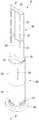
도 1은 본 발명의 실시예에 따른 가습 공기청정기의 구성을 보여주는 사시도이다.
도 2는 본 발명의 실시예에 따른 가습 공기청정기의 구성을 보여주는 평면도이다.
도 3 및 도 4는 본 발명의 실시예에 따른 가습 공기청정기의 구성을 보여주는 분해 사시도이다.
도 5는 도 1의 V-V'를 따라 절개한 단면도이다.
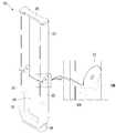
도 6은 본 발명의 실시예에 따른 토출장치의 구성을 보여주는 사시도이다.
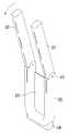
도 7은 본 발명의 실시예에 따른 토출장치의 구성을 보여주는 분해 사시도이다.
도 8a 및 도 8b는 본 발명의 실시예에 따른 토출장치의 상부 파트가 전방 및 후방으로 각각 틸팅된 모습을 보여주는 사시도이다.
도 9a 내지 도 9c는 본 발명의 실시예에 따른 토출장치가 틸팅될 때, 다양한 틸팅위치를 보여주는 도면이다.
도 10은 본 발명의 실시예에 따른 내부 파트가 인출된 모습을 보여주는 토출장치의 정면도이다.
도 11은 본 발명의 실시예에 따른 내부 파트가 인출된 모습을 보여주는 토출장치의 일부 구성에 대한 사시도이다.
도 12는 도 10의 XII-XII'를 따라 절개한 단면도이다.
도 13은 본 발명의 실시예에 따른 내부 파트가 인입된 모습을 보여주는 토출장치의 일부 구성에 대한 단면도이다.
도 14는 본 발명의 실시예에 따른 가습 공기청정기에서의 공기 유동을 보여주는 단면도이다.1 is a perspective view showing the configuration of a humidified air purifier according to an embodiment of the present invention.
2 is a plan view showing the configuration of a humidified air purifier according to an embodiment of the present invention.
3 and 4 are exploded perspective views showing the configuration of a humidified air purifier according to an embodiment of the present invention.
5 is a cross-sectional view taken along V-V' of FIG. 1.
6 is a perspective view showing the configuration of a discharge device according to an embodiment of the present invention.
7 is an exploded perspective view showing the configuration of a discharge device according to an embodiment of the present invention.
8A and 8B are perspective views illustrating a state in which an upper part of a discharge device according to an embodiment of the present invention is tilted forward and backward, respectively.
9A to 9C are views showing various tilting positions when a discharge device according to an embodiment of the present invention is tilted.
10 is a front view of a discharge device showing a state in which an inner part is withdrawn according to an embodiment of the present invention.
11 is a perspective view of a partial configuration of a discharge device showing a state in which an inner part is withdrawn according to an exemplary embodiment of the present invention.
12 is a cross-sectional view taken along line XII-XII' of FIG. 10.
13 is a cross-sectional view of a partial configuration of a discharge device showing a state in which an inner part is inserted according to an embodiment of the present invention.
14 is a cross-sectional view showing the flow of air in the humidified air purifier according to an embodiment of the present invention.
이하에서는 도면을 참조하여, 본 발명의 구체적인 실시예를 설명한다. 다만, 본 발명의 사상은 제시되는 실시예에 제한되지 아니하며, 본 발명의 사상을 이해하는 당업자는 동일한 사상의 범위 내에서 다른 실시예를 용이하게 제안할 수 있을 것이다.Hereinafter, specific embodiments of the present invention will be described with reference to the drawings. However, the spirit of the present invention is not limited to the presented embodiments, and those skilled in the art who understand the spirit of the present invention will be able to easily propose other embodiments within the scope of the same idea.
도 1은 본 발명의 실시예에 따른 가습 공기청정기의 구성을 보여주는 사시도이고, 도 2는 본 발명의 실시예에 따른 가습 공기청정기의 구성을 보여주는 평면도이다.1 is a perspective view showing a configuration of a humidified air purifier according to an embodiment of the present invention, Figure 2 is a plan view showing the configuration of a humidified air purifier according to an embodiment of the present invention.
도 1 및 도 2를 참조하면, 본 발명의 실시예에 따른 가습 공기청정기(10, 이하 공기청정기)에는, 지면에 놓여지는 베이스(100) 및 상기 베이스(100)의 상측으로 연장되는 본체(200,300)가 포함된다. 상기 베이스(100)는 원판 형상을 가지며, 상기 본체(200,300)는 상하 방향으로 길게 연장되는 통 형상을 가질 수 있다. 그리고, 상기 베이스(100)의 횡단면적은 상기 본체(200,300)의 횡단면적보다 크게 형성되므로, 공기청정기(10)의 구조적인 안정성이 구현될 수 있다.1 and 2, in the humidified air purifier 10 (hereinafter referred to as air purifier) according to an embodiment of the present invention, a base 100 placed on the ground and a main body 200,300 extending upwardly of the base 100 ) Is included. The base 100 may have a disk shape, and the
상기 본체(200,300)는 상기 베이스(100)에 대하여 가로 방향, 즉 상하 방향의 중심축을 기준으로 시계방향 또는 반시계 방향으로 회전할 수 있다.The
상기 본체(200,300)에는, 상기 베이스(100)의 상측에 구비되는 로어 바디(200)가 포함된다. 상기 로어 바디(200)는 원통 형상을 가지며 상기 베이스(100)의 상측으로 설정된 높이만큼 연장될 수 있다.The
상기 로어 바디(200)에는 내부가 비어 있는 원통 형상의 케이스(210,220)가 포함된다. 상기 케이스(210,220)의 하부 외주면에는, 공기가 흡입되는 흡입부(212)가 형성된다. 상기 흡입부(212)는 다수 개가 원주 방향으로 이격되어 형성되므로, 공기의 흡입용량이 증대될 수 있다.The
상기 케이스(210,220)의 상부에는 상기 케이스(210,220) 내부가 외부에 대하여 연통되도록 하는 관통공(228)이 포함된다. 상기 관통공(228)은 물통(240, 도 4 참조)이 위치되는 높이에 형성될 수 있다. 상기 물통(240)에 구비되는 밸브가 개방되었을 때, 상기 관통공(228)에 의하여 상기 물통(240)의 내부는 대기압을 형성하므로 상기 물통(240)에 저장된 물은 저수조(231, 도 4 참조)로 낙하할 수 있다.The upper portions of the
상기 케이스(210,220)에는, 제 1 케이스(210) 및 상기 제 1 케이스(210)의 상측에 맞춰지는 제 2 케이스(220)가 포함된다. 상기 제 1,2 케이스(210,220)의 내경 및 외경은 동일할 수 있다. 본 실시예에서는, 상기 제 1,2 케이스(210,220)가 분리 가능하게 제공되는 것으로 설명되나, 하나의 케이스로 일체 형성될 수도 있다.The
상기 본체(200,300)에는, 상기 로어 바디(200)의 상측에 구비되는 어퍼 바디(300)가 더 포함된다. 상기 어퍼 바디(300)는 상기 로어 바디(200)의 상단 중앙부에 분리 가능하게 결합될 수 있다. 그리고, 상기 어퍼 바디(300)는 상기 로어 바디(200)로부터 상방으로 연장되고 길쭉한 육면체의 형상을 가질 수 있다.The
상세히, 상기 로어 바디(200)의 상단 중앙부에는 상기 어퍼 바디(300)가 결합되고, 상단 양측부에는 급수를 위한 물통 커버(251,255)가 구비될 수 있다. 상기 물통 커버(251,255)는 사용자의 접근이 가능하도록 외부에 노출될 수 있다.In detail, the
상기 어퍼 바디(300)에는, 공기가 토출되는 토출공(325)을 가지는 토출장치(310)가 포함된다. 상기 토출공(325)은 상기 토출장치(310)의 전면부 양측에 구비되며, 상하 방향으로 다수 개가 배열될 수 있다.The
도 3 및 도 4는 본 발명의 실시예에 따른 가습 공기청정기의 구성을 보여주는 분해 사시도이고, 도 5는 도 1의 V-V'를 따라 절개한 단면도이다.3 and 4 are exploded perspective views showing the configuration of a humidified air purifier according to an embodiment of the present invention, and FIG. 5 is a cross-sectional view taken along V-V' of FIG. 1.
도 3 내지 도 5를 참조하면, 본 발명의 실시예에 따른 가습 공기청정기에는, 베이스(100) 및 상기 베이스(100)의 상측에 구비되는 로어 바디(200)가 포함된다.3 to 5, the humidified air purifier according to the embodiment of the present invention includes a
상기 베이스(100)는 개구된 상부를 가지며 원통 형상을 가지도록 구성될 수 있다. 상기 베이스(100)는 고정된 구성이다. 그리고, 상기 베이스(100)의 내부에는 로어 바디(200) 및 어퍼 바디(300)를 회전시키기 위한 구동장치가 구비될 수 있다.The base 100 may have an open upper portion and may be configured to have a cylindrical shape. The
상기 로어 바디(200)에는, 케이스(210,220) 및 상기 케이스(210,220)의 내부에 배치되는 다수의 부품이 포함된다. 상기 다수의 부품에는, 공기 청정기(10)의 송풍, 공기청정 및 가습기능을 수행하기 위한 부품들이 포함될 수 있다. The
상세히, 상기 로어 바디(200)에는, 상기 베이스(100)의 상측에 결합되는 지지장치(110)가 포함된다. 상기 지지장치(110)는 상기 베이스(100)의 개구된 상부를 덮도록 배치되며, 상기 베이스(100)의 구동장치에 의하여 좌우 방향으로 회전하도록 구성될 수 있다. 상기 로어 바디(200)는 상기 지지장치(110)에 결합되어, 상기 베이스(100)에 대하여 좌우 방향으로 회전할 수 있다. 일례로, 상기 지지장치(110)는 상기 제 1 케이스(210) 및 내부 케이스(265)에 결합될 수 있다.In detail, the
그리고, 상기 지지장치(110)는 원통 형상을 가지며, 상기 흡입부(212)에 연통되는 흡입 개구부(111a)를 가질 수 있다. 상기 흡입 개구부(111a)는 상기 지지장치(110)의 외주면에 형성될 수 있다.Further, the
상기 로어 바디(200)에는, 상기 지지장치(110)의 상측에 구비되는 내부 케이스(265)가 더 포함된다. 상기 내부 케이스(265)는 상단 및 하단이 개구된 원통 형상을 가질 수 있다. 상기 내부 케이스(265)의 내측 하부에는 필터(270)가 지지되며, 내측 상부에는 가습장치(230)가 지지될 수 있다. 그리고, 상기 내부 케이스(265)에는 체결부재에 의하여 송풍장치가 결합될 수 있다. 또한, 상기 내부 케이스(265)는 상대적으로 상하 방향으로 길게 연장되어 상기 제 1,2 케이스(210,220)에 결합(체결)될 수 있다.The
상기 로어 바디(200)에는, 상기 지지장치(110)의 상측에 배치되며 상기 지지장치(110)의 흡입 개구부(111a)를 통하여 흡입된 공기가 지나는 필터(270)가 더 포함된다. 상기 필터(270)는 상대적으로 낮은 높이(25~35mm)의 원통형상을 가지며 상기 내부 케이스(265)의 내경에 맞춰지는 외경을 가지도록 구성될 수 있다. 상기 필터(270)는 내부가 차 있는 필터로 구성되며, 공기는 상기 필터(270)의 저면으로 유입되어 필터링 되며, 필터링 된 공기는 상기 필터(270)의 상면으로 배출될 수 있다.The
상기 로어 바디(200)에는, 상기 필터(270)를 지지하는 링 형상의 필터지지부(275)가 더 포함된다. 상기 필터 지지부(275)는 상기 내부 케이스(265)의 내주면에 결합되며, 상기 필터(270)의 하부를 지지할 수 있다. 즉, 상기 필터 지지부(275)는 상기 내부 케이스(265)의 내주면으로부터 돌출되어 상기 필터(270)의 저면을 지지할 수 있다.The
상기 로어 바디(200)에는, 상기 필터(270)의 출구측에 배치되는 송풍장치가 포함된다. 일례로, 상기 송풍장치는 상기 필터(270)의 상측에 배치될 수 있다. 상세히, 상기 송풍장치에는, 공기 유동을 발생시키는 팬(280) 및 상기 팬(280)에 결합되는 팬 모터(282)가 포함된다.The
상기 팬(280)에는 축방향으로 원심팬이 포함될 수 있다. 상기 팬(280)에는 공기를 상방으로 경사지게 가이드 하는 다수의 블레이드가 포함될 수 있다. 상기 팬 모터(282)는 상기 팬(280)의 상측에 축 결합될 수 있다. 그리고, 상기 블레이드에는 팬(280)을 지나는 공기에서 발생되는 소음을 저감시키기 위한 흡음재(281)가 설치될 수 있다. 일례로, 상기 흡음재(281)는 다공성 부재로 구성되며, 상기 블레이드에 부착될 수 있다.The
상기 쉬라우드(260)는 상기 팬(280)의 흡입측에 배치되며, 상기 팬(280)의 하단부를 향하여 공기를 모아주도록 라운드진 내면을 가질 수 있다. 상기 쉬라우드(260)의 하단부는 상기 팬(280)의 하단부보다 높게 위치될 수 있다. 따라서, 필터(270)를 통과한 공기는 상기 쉬라우드(260)의 하단부로 유입되어 상방으로 유동하며, 상기 팬(280)으로 흡입될 수 있다.The
상기 송풍장치에는, 상기 쉬라우드(260)의 상측에 결합되는 홀더(284)가 더 포함된다. 상기 홀더(284)는 상기 쉬라우드(260)보다 더 무겁게 형성될 수 있다. 상기 홀더(284)는 금속소재로 구성되며, 상기 쉬라우드(260)는 플라스틱 사출물로 구성된다. 일례로, 상기 홀더(284)는 알루미늄 소재로 구성될 수 있다.The blowing device further includes a
상기 홀더(284)의 무게는 상기 쉬라우드(260) 무게의 3배 이상으로 형성된다. 바람직하게는, 상기 홀더(284)의 무게는 상기 쉬라우드(260) 무게의 약 5배로 형성될 수 있다. 이와 같이, 상기 홀더(264)가 상기 쉬라우드(260)보다 무겁게 형성되어 상기 홀더(264)는 상기 쉬라우드(260)를 하방으로 가압하게 되어, 쉬라우드(260)에서의 진동에 따른 소음이 저감될 수 있다.The weight of the
상기 홀더(284)의 내부에는 상기 팬(280)이 위치될 수 있다. 즉, 상기 홀더(284)는 상기 팬(280)의 설치공간을 제공하는 팬 하우징으로서 이해될 수 있다. 상기 홀더(284)의 상단부 및 하단부는 공기의 통과가 가능하도록 개구되어 형성된다. 그리고, 상기 쉬라우드(260)와 상기 홀더(284)가 이루는 내부 공간에 상기 팬(280)이 설치될 수 있다.The
상기 송풍장치에는, 상기 홀더(284)의 상측에 구비되며, 상기 팬(280)을 통과하면서 상기 홀더(284)의 내주면측으로 발산되는 공기를 상방으로 모아주는 디퓨저(286)가 더 포함된다. 상기 디퓨저(286)는 상기 팬 모터(282)에 결합될 수 있다. 즉, 상기 팬(280)과 디퓨저(286)는 하나의 팬 모터(282)에 결합되어 회전할 수 있다.The blowing device further includes a
상기 송풍장치에는, 상기 디퓨저(286)의 상측에 배치되는 디퓨저 가이드(288)가 더 포함된다. 상기 디퓨저 가이드(288)는 상하부가 개구되어 상기 디퓨저(286)의 외주면을 감싸도록 구성된다. 상기 디퓨저(286)의 외주면과 상기 디퓨저 가이드(288)의 내주면 사이에는, 상기 디퓨저(286)를 지나는 공기 유로가 형성한다.The air blower further includes a
상기 로어 바디(200)에는, 상기 송풍장치의 상측에 배치되는 가습장치(230)가 더 포함된다. 상세히, 상기 가습장치(230)는 상기 디퓨저(286)의 출구측, 즉 상기 디퓨저(286)의 상측에 배치될 수 있다.The
상기 가습장치(230)는 상기 내부 케이스(265)의 상부에 지지될 수 있다. 상세히, 상기 가습장치(230)에는, 물통(240) 및 상기 물통(240)에 저장된 물이 집수되는 저수조(231)가 포함된다. 상기 물통(240)은 상기 저수조(231)의 상측에 안착될 수 있다. 그리고, 상기 저수조(231)에는 가습매체(235)가 설치될 수 있다.The
상기 물통(240)에는 상부가 개방된 물통 본체(241)가 포함된다. 일례로, 상기 물통 본체(241)는 소정의 높이를 가지며 대략 원통의 형상을 가질 수 있다. 상기 물통(240)의 상부에는, 물의 공급이 이루어질 수 있는 물 유입부(245)가 형성된다. 상기 물 유입부(245)에는 좌우 방향으로 이격되는 제 1 유입부(245a) 및 제 2 유입부(245b)가 포함된다. 상기 제 1,2 유입부(245a,245b)에는 가습 커버(250)가 분리 가능하게 결합될 수 있다.The
상기 물통(240)의 상부 및 하부는 개구되어, 공기유로(241a)를 형성한다. 상기 공기유로(241a)에는, 상기 송풍장치에서 토출된 공기가 유동하며, 공기는 상기 공기유로(241a)를 따라 상방으로 유동할 수 있다. 상기 공기유로(241a)는 상방으로 갈수록 그 폭이 좁아지도록 구성될 수 있다. 그리고, 상기 공기유로(241a)는 상기 제 1,2 유입부(245a,245b)의 사이에 배치될 수 있다.The upper and lower portions of the
상기 저수조(231)는 상기 물통(240)의 하측에 결합된다. 일례로, 상기 저수조(231)의 상단 테두리 외측에 상기 물통(240)의 하부 테두리가 배치되도록, 상기 저수조(231)의 상부는 상기 물통(240)의 하부에 삽입될 수 있다.The
상기 저수조(231)는 상부 및 하부가 개구되어 공기유로를 형성하고, 그 외측에 저수조 저장공간(231a)이 배치되도록 구성될 수 있다. 즉, 상기 저수조 저장공간(231a)은 상기 저수조(231)의 공기유로(231b)를 둘러싸도록 배치될 수 있다. 상기 물통(240)의 공기유로(241a)를 "물통 유로", 상기 저수조(231)의 공기유로(231b)를 "저수조 유로"라 이름할 수 있다. 그리고, 상기 물통(240)에 저장된 물은 상기 저수조(231)로 낙하하여, 상기 저수조 저장공간(231a)에 저장될 수 있다.The
상기 저수조(231)에는, 가습매체(235)가 구비된다. 상기 가습매체(235)는 물의 흡수가 용이한 소재로 구성될 수 있다. 일례로, 상기 가습매체(235)는 다수의 통공이 형성되는 섬유 또는 합성 섬유로 구성될 수 있다. 상기 다수의 통공을 통하여, 공기가 유동할 수 있다.A
상기 가습매체(235)는 상기 저수조 저장공간(231a)의 물에 담겨지도록 배치되며, 상기 공기유로(231b)를 덮도록 배치될 수 있다. 상기 가습매체(235)의 일부분이 물에 적셔지면, 가습매체(235) 전체 부분으로 물의 확산이 이루어질 수 있다. 그리고, 상기 공기유로(231b)를 통하여 상방으로 유동하는 공기는 상기 가습매체(235)에 의하여 가습될 수 있다.The
상기 가습장치(230)에는, 상기 물통(240)의 상측에 분리 가능하게 구비되는 가습커버(250)가 더 포함된다. 상기 물통(240)의 상단부에는 개구된 물 유입부(245)가 형성되며, 상기 가습커버(250)는 상기 물 유입부(245)를 개폐하도록 구성될 수 있다.The
상기 가습커버(250)가 분리되면, 사용자는 상기 물통(240)으로 물을 공급할 수 있다. 그리고, 상기 송풍장치를 지난 공기는 상기 가습매체(235)를 지나면서 가습되며, 가습된 공기는 상방으로 유동하여 어퍼 바디(300)측으로 유입된다.When the
상세히, 상기 가습 커버(250)는 물통(240)의 물 유입부(245a,245b)를 커버할 수 있다. 상기 가습 커버(250)는 제 2 케이스(220)에 지지되며 상기 제 2 케이스(220)의 개구된 상부 중 적어도 일부분을 차페하도록 구성될 수 있다. 상기 물통(240)의 물 유입부(245a,245b)는 상기 제 2 케이스(220)의 상단부와 대응되는 위치에 배치될 수 있다.In detail, the
상기 가습 커버(250)에는, 제 1 커버(251) 및 상기 제 1 커버(251)에 분리 가능하게 결합되는 제 2 커버(255)가 포함된다. 상기 제 1 커버(251)에는, 링 형상의 커버본체 및 제 1 물 유입부(245a) 또는 제 2 물 유입부(2435b)를 커버하는 차폐부(252b)가 포함된다. 상기 차폐부(252b)는 상기 커버본체로부터 제 1 커버(251)의 중심부 방향으로 연장되며 반원판의 형상을 가질 수 있다. 상기 커버본체와 상기 차폐부(252b)는 일체로 구성될 수 있다.The
상기 제 2 커버(255)는 대략 반 원판의 형상을 가질 수 있다. 일례로, 상기 제 2 커버(255)는 상기 차폐부(252b)의 형상과 유사할 수 있다.The
상기 가습커버(250)에는, 물통(240)의 물통 유로(241a)에 연통되는 공기유로(250a)가 형성된다. 상기 공기유로(250a)를 "커버유로"라 이름할 수 있다. 상기 커버유로(250a)는 상기 가습커버(250)의 중앙부에 형성되며, 상기 커버유로(250a)의 양측에는 상기 차폐부(252b) 및 상기 제 2 커버(255)가 위치될 수 있다. 즉, 상기 커버유로(250a)는 상기 차폐부(252b)와 상기 제 2 커버(255)의 사이에 형성될 수 있다.The
상기 차폐부(252b)는 상기 제 1,2 유입부(245a,245b) 중 어느 하나를 차폐하며, 상기 제 2 커버(255)는 상기 다른 하나를 차폐하도록 배치될 수 있다.The shielding
상기 커버유로(250a)에는, 토출장치(310)의 물통 결합부(328)가 결합될 수 있다. 상기 커버유로(250a)를 통하여 상방으로 유동하는 공기는 상기 물통 결합부(328)를 통하여 상기 토출장치(310)의 내부로 유입될 수 있다.The water
상기 케이스(210,220)는 상기 로어 바디(200)의 외관을 형성하며, 상기 내부 케이스(265)의 외주면을 둘러싸도록 배치될 수 있다.The
상기 로어 바디(200)의 상측에는 어퍼 바디(300)가 결합된다. 상기 어퍼 바디(300)는 상기 가습장치(230)의 상측에 분리 가능하게 결합될 수 있다. 상기 어퍼 바디(300)는 상기 로어 바디(200)에 결합되어, 함께 좌우 방향으로 회전할 수 있다.The
상기 어퍼 바디(300)에는 상기 가습장치(230)를 통과한 공기를 공기 청정기(10)로부터 배출시키는 토출장치(310)가 포함된다. 그리고, 상기 토출장치(310)에는 온풍 기능을 수행하기 위한 가열장치가 포함될 수 있다. 상기 가열장치에는, 히터(330)가 포함될 수 있다.The
상세히, 상기 토출장치(310)에는, 상기 가습장치(230)를 통과한 공기의 토출유로를 형성하는 토출본체(320)가 포함된다. 상기 토출유로는 상기 토출본체(320)의 내부공간으로서 정의될 수 있다.In detail, the
상기 토출본체(320)는 상하 방향으로 연장되는 2개의 토출부(320a,320b)가 포함된다. 상기 2개의 토출부(320a,320b)에는, 상기 로어 바디(200)의 상단부 일측에 배치되는 제 1 토출부(320a) 및 상기 로어 바디(200)의 상단부 타측에 배치되는 제 2 토출부(320b)가 포함된다.The
상기 제 1,2 토출부(320a,320b)에는, 각각 토출공(325)이 형성된다. 그리고, 상기 토출공(325)은 상기 제 1,2 토출부(320a,320b)에 각각 다수 개가 구비되어 상하 방향으로 배열될 수 있다.Discharge holes 325 are formed in the first and
상기 토출본체(320)에는, 상기 제 1,2 토출부(320a,320b)의 하부를 연결하는 토출 연결부(320c)가 더 포함된다. 상기 토출 연결부(320c)는 상기 제 1 토출부(320a)의 하부로부터 상기 제 2 토출부(320b)의 하부를 향하여 가로 방향으로 연장될 수 있다. 그리고, 상기 토출본체(320)에는, 상기 가습 장치(230)의 물통(240)에 결합되는 물통 결합부(328)가 구비될 수 있다. 상기 물통 결합부(328)는 상기 토출 연결부(320c)로부터 하방으로 연장되며, 물통(240)의 공기유로(241a)에 연통될 수 있다.The
상기 토출본체(320)는, 상기 제 1,2 토출부(320a,320b) 및 상기 토출 연결부(320c)의 구성에 의하여, 절곡된 형상을 가질 수 있다. 일례로, U 형상을 가지도록 구성될 수 있다.The
상기 토출본체(320)에는, 공기를 가열하기 위한 히터(330)가 구비된다. 상기 히터(330)는 상기 토출 유로에 배치될 수 있다. 상기 히터(330)에는 면상 히터가 포함된다. 그리고, 상기 히터(330)는 상기 토출 본체(320)의 하부에 배치되며, 복수 개가 제공되어 상기 토출 본체(320)의 전방부 및 후방부에 각각 배치될 수 있다. 일례로, 상기 히터(330)에는, 제 1 히터(331) 및 제 2 히터(332)가 포함될 수 있다 (도 6 참조).The
이하에서는, 본 발명의 실시예에 따른 토출장치의 틸팅구조에 대하여 설명한다. 도 6은 본 발명의 실시예에 따른 토출장치의 구성을 보여주는 사시도이고, 도 7은 본 발명의 실시예에 따른 토출장치의 구성을 보여주는 분해 사시도이고, 도 8a 및 도 8b는 본 발명의 실시예에 따른 토출장치의 상부 파트가 전방 및 후방으로 각각 틸팅된 모습을 보여주는 사시도이고, 도 9a 내지 도 9c는 본 발명의 실시예에 따른 토출장치가 틸팅될 때, 다양한 틸팅위치를 보여주는 도면이다.Hereinafter, a tilting structure of a discharge device according to an embodiment of the present invention will be described. 6 is a perspective view showing a configuration of a discharge device according to an embodiment of the present invention, FIG. 7 is an exploded perspective view showing the configuration of a discharge device according to an embodiment of the present invention, and FIGS. 8A and 8B are an embodiment of the present invention. Is a perspective view showing a state in which the upper part of the discharge device according to is tilted forward and backward, respectively, and FIGS. 9A to 9C are views showing various tilting positions when the discharge device according to an embodiment of the present invention is tilted.
도 6 내지 도 9c를 참조하면, 본 발명의 실시예에 따른 토출장치(310)에는, 하부 파트(321) 및 상기 하부 파트(321)의 상측에 틸팅 가능하게 구비되는 상부 파트(322)가 포함된다. 상기 상부 파트(322)는 복수 개가 구비되어 상기 하부 파트(321)의 양측에 결합될 수 있다.6 to 9C, the
그리고, 상기 하부파트(321)의 전면 및 상기 상부 파트(322)의 전면에 각각 토출공(325)이 형성될 수 있다. 상세히, 상기 토출공(325)에는, 상기 하부파트(321)에 구비되는 하부 토출공(325a) 및 상기 상부파트(322)에 구비되는 상부 토출공(325b)이 포함된다.In addition, discharge holes 325 may be formed in the front of the
상기 하부 파트(321)에는, 상기 가습 장치(230)의 물통(240)에 결합되는 물통 결합부(328)가 포함될 수 있다. 상기 물통 결합부(328)는 상기 하부 파트(321)의 하부에 구비될 수 있다.The
상기 하부 파트(321)의 내부에는, 히터(331,332)가 구비된다. 상기 히터(331,332)에는, 상기 하부 파트(321)의 전방부에 구비되는 제 1 히터(331) 및 후방부에 구비되는 제 2 히터(332)가 포함된다.
상기 하부 파트(321)는 U 형상으로 절곡되는 형상을 가질 수 있다. 상기 토출장치(310)에는, 상기 하부 파트(321)의 양측을 연결하는 연결 플레이트(329)가 더 포함된다. 상기 연결 플레이트(329)는 상하 방향으로 연장된 상기 하부 파트(321)의 양측부 사이에 배치될 수 있다. 상기 연결 플레이트(329)에 의하여, 절곡된 형상을 가지는 하부 파트(321)의 변형을 방지할 수 있다.The
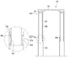
상기 토출장치(310)에는, 상기 상부 파트(322)의 틸팅을 위한 틸팅 가이드장치가 더 포함된다. 상기 틸팅 가이드장치에는, 상기 하부 파트(321)의 상부에 구비되며 제 1 힌지공(321b)이 형성되는 제 1 힌지부(321a)가 포함된다. 그리고, 상기 틸팅 가이드장치에는, 상기 상부 파트(322)의 하부에 구비되며 제 2 힌지공(322b)이 형성되는 제 2 힌지부(322a)가 더 포함된다.The
상기 제 1 힌지부(321a)는 상기 하부 파트(321)의 양측에 각각 구비되고, 복수의 상부 파트(322) 각각에는, 상기 제 1 힌지부(321a)에 결합되는 제 2 힌지부(322a)가 구비될 수 있다.The
상기 제 1 힌지부(321a)와 상기 제 2 힌지부(322a)는 힌지핀(323)에 의하여 연결될 수 있다. 일례로, 상기 제 2 힌지부(322a)는 상기 제 1 힌지부(321a)의 내부에 배치되고, 상기 힌지핀(323)은 상기 제 1 힌지공(321b) 및 상기 제 2 힌지공(322b)에 결합될 수 있다.The
상기 힌지핀(323)은 상기 상부 파트(322)의 양측에 구비될 수 있다. 일례로, 상기 상부 파트(322)는 상기 하부 파트(321)의 상부 양측에 2개가 구비되고, 상기 힌지핀(323)은 각 상부 파트(322)의 양측에 구비되어 총 4개의 힌지핀(323)이 구비될 수 있다.The hinge pins 323 may be provided on both sides of the
상기 하부 파트(321)는 상기 물통(240)의 상측에 고정되고, 상기 상부 파트(322)는 상기 힌지핀(323)을 중심으로 틸팅 가능할 수 있다. 상기 힌지핀(323)은 상기 상부 파트(322)의 하부에 배치되며, 상기 상부 파트(322)는 탑-다운(Top Down) 방식으로 회전할 수 있다.The
상기 틸팅 가이드장치에는, 상기 상부 파트(322)로부터 하방으로 연장되며, 상기 상부 파트(322)가 틸팅할 때 상기 상부 파트(322)의 틸팅각도를 제한하는 스토퍼(324a,324b)가 구비된다. 상기 스토퍼(324a,324b)는 상기 하부 파트(321)의 내부에 삽입되며, 상기 하부 파트(321)의 내면과 간섭되도록 작용할 수 있다.The tilting guide device is provided with
상기 스토퍼(324a,324b)에는, 상기 상부 파트(322)의 전방부에 구비되는 제 1 스토퍼(324a) 및 상기 상부 파트(322)의 후방부에 구비되는 제 2 스토퍼(324b)가 포함된다. 상기 제 1 스토퍼(324a)는 상기 상부 파트(322)의 전면으로부터 후방으로 하향 경사지게 연장되며, 상기 제 2 스토퍼(324b)는 상기 상부 파트(322)의 후면으로부터 전방으로 하향 경사지게 연장될 수 있다.The
상기 상부 파트(322)의 상부가 상기 힌지핀(323)보다 전방에 위치하도록 틸팅할 때, 상기 제 2 스토퍼(324b)는 상기 하부 파트(321)의 내면에 간섭될 수 있다 (도 9b 참조). 따라서, 상기 상부 파트(322)의 더 이상의 틸팅은 방지될 수 있다. 이 때, 상기 상부 파트(322)의 틸팅위치를 "제 1 위치"라 이름할 수 있다.When the upper part of the
상기 상부 파트(322)가 상기 제 1 위치에 있을 때, 상기 상부 파트(322)는 상기 힌지핀(323)을 지나는 상하 방향의 수직선(ℓ1)에 대하여 전방으로 제 1 설정각도(α1)만큼 경사지게 위치될 수 있다. 일례로, 상기 제 1 설정각도(α1)는 10~20°의 범위에 있을 수 있다.When the
그리고, 상기 상부 파트(322)의 상부가 상기 힌지핀(323)보다 후방에 위치하도록 틸팅할 때, 상기 제 1 스토퍼(324a)는 상기 하부 파트(321)의 내면에 간섭될 수 있다 (도 9c 참조). 따라서, 상기 상부 파트(322)의 더 이상의 틸팅은 방지될 수 있다. 이 때, 상기 상부 파트(322)의 틸팅위치를 "제 2 위치"라 이름할 수 있다.In addition, when tilting so that the upper part of the
상기 상부 파트(322)가 상기 제 2 위치에 있을 때, 상기 상부 파트(322)는 상기 힌지핀(323)을 지나는 상하 방향의 수직선(ℓ1)에 대하여 후방으로 제 2 설정각도(α2)만큼 경사지게 위치될 수 있다. 일례로, 상기 제 2 설정각도(α2)는 상기 제 1 설정각도(α1)와 동일할 수 있다.When the
이와 같이, 토출공(325)이 형성되는 상부 파트(322)가 전방 또는 후방으로 틸팅될 수 있으므로, 사용자는 약간의 힘을 이용하여 상기 상부 파트(322)를 조작하여 틸팅할 수 있다. 따라서, 상기 상부 파트(322)에서 토출되는 공기의 방향을 자유롭게 조절할 수 있다.In this way, since the
이하에서는, 본 발명의 실시예에 따른 토출장치에 구비되는 내부 파트의 상하방향 슬라이딩 구조에 대하여 설명한다. 도 10은 본 발명의 실시예에 따른 내부 파트가 인출된 모습을 보여주는 토출장치의 정면도이고, 도 11은 본 발명의 실시예에 따른 내부 파트가 인출된 모습을 보여주는 토출장치의 일부 구성에 대한 사시도이고, 도 12는 도 10의 XII-XII'를 따라 절개한 단면도이고, 도 13은 본 발명의 실시예에 따른 내부 파트가 인입된 모습을 보여주는 토출장치의 일부 구성에 대한 단면도이다.Hereinafter, a vertical sliding structure of an inner part provided in a discharge device according to an embodiment of the present invention will be described. FIG. 10 is a front view of a discharging device showing a state in which an inner part is withdrawn according to an embodiment of the present invention, and FIG. 11 is a perspective view of a partial configuration of a discharging device showing a state in which the inner part is withdrawn according to an embodiment of the present invention 12 is a cross-sectional view taken along line XII-XII' of FIG. 10, and FIG. 13 is a cross-sectional view of a partial configuration of a discharge device showing a state in which an inner part is inserted according to an embodiment of the present invention.
도 10 내지 도 13을 참조하면, 본 발명의 실시예에 따른 토출장치(310)에는, 하부 파트(321)와, 상기 하부 파트(321)의 상측에 틸팅 가능하게 구비되는 상부 파트(322) 및 상기 상부 파트(322)의 내부에 상하 방향으로 이동 가능하게 구비되는 내부 파트(326)가 포함된다. 상기 상부 파트(322)의 상단부(322c)는 상기 내부 파트(326)가 삽입될 수 있도록, 개방되도록 구성될 수 있다.10 to 13, in the
상기 하부 파트(321) 및 상기 상부 파트(322)는 상기 토출 본체(320)를 구성하며, 상기 내부 파트(326)는 상하 방향으로 연장되어 상기 토출 본체(320)의 내부에 인입되거나 그로부터 인출되도록 구성될 수 있다.The
상기 내부 파트(326)는 복수 개가 구비되며, 상기 복수 개의 내부 파트(326)는 복수 개의 상부 파트(322)의 내부에 인입 가능하게 구비될 수 있다. 일례로, 도면에 도시되는 바와 같이, 상기 내부 파트(326)는 2개가 구비되며, 상기 2개의 내부 파트(326)는 상기 2개의 상부 파트(322)에 인입되거나, 상기 상부 파트(322)로부터 인출될 수 있다.The plurality of
상기 토출장치(310)에는, 상기 내부 파트(326)의 상측에 결합되는 상부 커버(370)가 더 포함된다. 상기 상부 커버(370)는 가로 방향으로 연장되어 복수 개의 내부 파트(326)의 상면에 결합될 수 있다. 상기 상부 커버(370)는 상기 복수 개의 내부 파트(326)와 함께 상하 방향으로 이동될 수 있다.The
상기 내부 파트(326)의 외면에는, 상하 방향으로 연장되는 가이드 홈(326b)이 형성된다. 그리고, 상기 상부 파트(322)에는 상기 가이드 홈(326b)을 따라 슬라이딩 되는 서포터(327a)가 포함된다. 상기 서포터(327a)는 상기 상부 파트(322)의 상부 내면에 구비되며, 상기 가이드 홈(326b)에 삽입될 수 있다. 상기 내부 파트(326)가 상방 또는 하방으로 이동할 때, 상기 서포터(327a)는 상기 가이드 홈(326b)을 따라 슬라이딩 될 수 있다.A
다만, 이와는 반대로 상기 내부 파트에 서포터가 구비되고, 상기 상부 파트에 가이드 홈이 형성될 수도 있다.However, on the contrary, a supporter may be provided in the inner part, and a guide groove may be formed in the upper part.
상기 상부 파트(322)에는, 상기 서포터(327a)로부터 돌출되는 돌기(327b)가 포함된다. 일례로, 상기 돌기(327b)는 상기 서포터(327a)로부터 상기 상부 파트(322)의 내부 방향으로 돌출될 수 있다. 그리고, 상기 내부 파트(326)에는 상기 돌기(327b)가 삽입되는 돌기 홈(326c)이 형성된다. 상기 돌기 홈(326c)은 상기 가이드 홈(326b)에서 함몰되도록 구성될 수 있다.The
상기 내부 파트(326)가 상방으로 이동하여 상기 상부 파트(322)로부터 최대거리 만큼 인출되면, 상기 돌기(327b)는 상기 돌기 홈(326c)에 삽입될 수 있다. 따라서, 상기 내부 파트(326)는 상기 상부 파트(322)에 걸림이 이루어질 수 있으며, 상기 내부 파트(326)가 하방으로 자유 낙하되는 것을 방지할 수 있다.When the
한편, 사용자는 상기 내부 파트(326)를 하방으로 이동시키기 위하여, 상기 돌기(327b)가 상기 돌기 홈(326c)으로 이탈될 정도로 약간의 힘을 가할 수 있다. 상기 돌기(327b)가 상기 돌기 홈(326c)으로부터 이탈되면, 상기 내부 파트(326)는 하방으로 이동하여 상기 상부 파트(322)의 개방된 상단부(322c)를 통하여 인입될 수 있다.Meanwhile, in order to move the
상기 내부 파트(326)의 전면에는 내부 토출공(326a)이 형성된다. 상기 내부 파트(326)가 상기 상부 파트(322)의 내부로 인입된 상태에서, 상기 내부 토출공(326a)은 상기 상부 파트(322)의 토출공(325)과 전후 방향으로 정렬될 수 있다. 그리고, 상기 내부 파트(326)는 상기 상부 파트(322)에 의하여 가려지게 된다. 따라서, 상기 토출장치(310) 내부의 공기는 정렬된 상기 토출공(325)과 상기 내부 토출공(326a)을 통하여 전방으로 배출될 수 있다. 즉, 상기 내부 파트(326)가 공기의 토출을 방해하는 것을 방지할 수 있다.An
반면에, 상기 내부 파트(326)가 상기 상부 파트(322)로부터 상방으로 인출된 상태에서, 상기 내부 토출공(326a)은 상기 토출공(325)보다 높은 위치에 배치되며 외부로 노출될 수 있다. 따라서, 상기 내부 토출공(326a)은 상기 토출공(325)과는 별도로 추가 토출공으로서 작용하므로, 토출면적이 증가하는 효과를 가져올 수 있다.On the other hand, when the
상기 상부 파트(322)의 개방된 상단부의 내측면에는 상기 내부 파트(326)의 인입 또는 인출상태를 감지하는 센서(380a,380b)가 포함된다. 일례로, 상기 센서(380a,380b)에는 복수 개의 상부 파트(322) 중 어느 하나에 구비되는 제 1 센서(380a) 및 다른 하나에 구비되는 제 2 센서(380b)가 포함된다.
상기 내부 파트(326)에는 상기 센서(380a,380b)에 작용할 수 있는 턱(326d)이 더 포함된다. 상기 턱(326d)은 상기 가이드 홈(326b)의 상단부를 형성하며, 상기 가이드 홈(326b)에 비하여 외측 방향으로 상대적으로 더 돌출되도록 구성될 수 있다.The
상기 내부 파트(326)가 상기 상부 파트(322)에 인입된 상태에서, 상기 턱(326d)은 상기 센서(380a,380b)와 작용할 수 있도록, 상기 센서(380a,380b)에 접촉하거나 설정거리 이내로 위치될 수 있다. 일례로, 상기 센서(380a,380b)에는 기계식, 전자식, 자기식 또는 광학식으로 구성된 위치감지 센서가 포함될 수 있다.In a state in which the
상기 내부 파트(326)가 상기 상부 파트(322)의 내부에 인입되면, 상기 센서(380a,380b)는 ON 될 수 있다. 상기 센서(380a,380b)가 ON 되면, 상기 팬(280)의 회전수는 "제 1 회전수"를 형성할 수 있다.When the
반면에, 상기 내부 파트(326)가 상기 상부 파트(322)로부터 인출된 상태(도 12의 상태)일 때, 상기 센서(380a,380b)는 OFF 될 수 있다. 상기 센서(380a,380b)가 OFF 되면, 상기 팬(280)의 회전수는 "제 2 회전수"를 형성할 수 있다. 상기 제 2 회전수는 상기 제 1 회전수보다 클 수 있다.On the other hand, when the
즉, 상기 내부 파트(326)가 상방으로 이동하여 상기 상부 파트(322)로부터 인출되었을 때 토출면적이 증가하게 되므로, 그에 대응하여 상기 팬(280)의 회전수를 증가하여 상기 토출공(325) 및 상기 내부 토출공(326a)으로부터 충분한 양의 공기가 토출될 수 있도록 한다.That is, since the
반면에, 상기 내부 파트(326)가 하방으로 이동하여 상기 상부 파트(322)의 내부로 인입되었을 때 토출면적이 상대적으로 감소하게 되므로, 그에 대응하여 상기 팬(280)의 회전수를 상대적으로 감소하여 적당한 양의 공기유동이 발생될 수 있도록 한다.On the other hand, when the
도 14는 본 발명의 실시예에 따른 가습 공기청정기에서의 공기 유동을 보여주는 단면도이다.14 is a cross-sectional view showing the flow of air in the humidified air purifier according to an embodiment of the present invention.
도 14를 참조하면, 공기청정기(10)에서의 공기유동을 설명한다. 팬(280)이 구동하면, 공기는 공기청정기(10)의 하부에 형성된 흡입부(212)를 통하여 로어 바디(200)로 흡입된다. 흡입된 공기는 상방으로 유동하여 필터(270)의 저면으로 유입되어 상면을 통하여 배출될 수 있다.Referring to FIG. 14, the air flow in the
상기 필터(270)에서 배출된 공기는 쉬라우드(260)로 흡입되어 팬(280)을 통과하고 홀더(284) 및 디퓨저(286)를 통과한다. 상기 디퓨저(286)에서 배출된 공기는 가습장치(230)의 저수조 유로(231b) 및 물통 유로(241a)를 통하여 상방으로 유동한다. 그리고, 상기 가습장치(230)에서 배출된 공기는 토출장치(310)의 물통 연결부(328)를 통하여 토출 본체(320)의 내부로 유동한다.The air discharged from the
공기는 상기 토출 본체(320)의 전방부 및 후방부에 배치된 제 1,2 히터(331,332)를 지나면서 가열되며, 가열된 공기는 토출 본체(320)의 토출공(325) 또는 내부 파트(326)의 내부 토출공(326a)을 통하여 토출될 수 있다.The air is heated while passing through the first and
10 : 공기 청정기100 : 베이스
200 : 로어 바디210,220 : 케이스
230 : 가습장치231 : 저수조
240 : 물통250 : 가습 커버
260 : 쉬라우드265 : 내부 케이스
270 : 필터280 : 팬
284 : 홀더286 : 디퓨저
300 : 어퍼 바디310 : 토출장치
320 : 토출 본체321 : 하부 파트
322 : 상부 파트323 : 힌지핀
326 : 내부 파트330 : 히터10: air cleaner 100: base
200: lower body 210,220: case
230: humidification device 231: water storage tank
240: water bottle 250: humidification cover
260: shroud 265: inner case
270: filter 280: fan
284: holder 286: diffuser
300: upper body 310: discharge device
320: discharge body 321: lower part
322: upper part 323: hinge pin
326: inner part 330: heater
Claims (15)
Translated fromKorean상기 로어 바디는,
상기 케이스의 하부에 설치되는 필터; 및
상기 필터의 출구측에 배치되는 송풍장치를 구비하고,
상기 어퍼 바디는,
상기 송풍장치를 통과한 공기의 토출 유로가 형성되는 토출 본체를 포함하고,
상기 토출 본체는,
상하 방향으로 연장되며 이격되어 구비되는 제 1,2 토출부; 및
상기 토출본체가 절곡된 형상을 가지도록 상기 제 1,2 토출부의 하부를 연결하는 토출 연결부를 포함하고,
상기 제 1,2 토출부는,
상기 토출연결부에 의해 연결되는 하부 파트;
상기 하부 파트의 상측에 구비되는 상부 파트; 및
상기 상부 파트의 외부로 인출될 수 있도록 상기 파트의 내부에 구비되는 내부 파트를 포함하고,
상기 하부 파트, 상기 상부 파트 및 상기 내부 파트는 상기 토출 유로를 지난 공기를 배출하도록 전면에 하부 토출공, 상부 토출공 및 내부 토출공을 각각 포함하고,
상기 상부 파트는 상기 하부 파트로부터 틸팅 가능하게 구비되는 가습 공기청정기.An air purifier comprising a lower body having a case forming a suction part and an upper body coupled to an upper side of the lower body and having a discharge hole,
The lower body,
A filter installed under the case; And
It has a blowing device disposed on the outlet side of the filter,
The upper body,
And a discharge body in which a discharge passage for air passing through the blower is formed,
The discharge main body,
First and second discharge units extending in the vertical direction and spaced apart from each other; And
And a discharge connection part connecting lower portions of the first and second discharge parts so that the discharge body has a bent shape,
The first and second discharge units,
A lower part connected by the discharge connector;
An upper part provided on the upper side of the lower part; And
Including an inner part provided inside the part so as to be drawn out to the outside of the upper part,
The lower part, the upper part, and the inner part each include a lower discharge hole, an upper discharge hole, and an inner discharge hole on a front surface to discharge air that has passed through the discharge flow path,
The upper part is a humidified air purifier provided to be tiltable from the lower part.
상기 상부 파트의 상단부는 개구되며,
상기 내부 파트는 상기 개구된 상단부를 통하여 인출 또는 인입되는 가습 공기청정기.The method of claim 1,
The upper end of the upper part is opened,
The inner part is a humidified air purifier that is drawn out or drawn in through the opened upper end.
상기 내부 파트는 상방 또는 하방으로 이동되는 가습 공기청정기.The method of claim 2,
The inner part is a humidified air purifier that moves upward or downward.
상기 내부 파트 및 상기 상부 파트 중 어느 하나의 외면에 형성되며, 상하 방향으로 연장되는 가이드 홈; 및
상기 내부 파트 및 상기 상부 파트 중 다른 하나에 구비되며, 상기 가이드 홈에 삽입되어 이동하는 서포터가 더 포함되는 가습 공기청정기.The method of claim 3,
A guide groove formed on an outer surface of one of the inner part and the upper part and extending in a vertical direction; And
The humidification air purifier further includes a supporter provided in the other one of the inner part and the upper part and inserted into the guide groove to move.
상기 서포터로부터 돌출되는 돌기; 및
상기 가이드 홈에 함몰되어 형성되는 돌기 홈이 더 포함되며,
상기 내부 파트가 상방으로 이동하여 상기 상부 파트로부터 최대거리 만큼 인출되면, 상기 돌기는 상기 돌기 홈에 삽입되는 가습 공기청정기.The method of claim 4,
A protrusion protruding from the supporter; And
A protrusion groove formed by being depressed in the guide groove is further included,
When the inner part moves upward and is extracted by a maximum distance from the upper part, the protrusion is inserted into the protrusion groove.
상기 내부 파트가 상기 상부 파트로부터 인출된 상태에서, 상기 내부 토출공은 상기 상부 파트의 외부로 노출되며,
상기 내부 파트가 상기 상부 파트에 인입된 상태에서, 상기 내부 토출공과 상기 상부 토출공은 전후 방향으로 정렬되는 가습 공기청정기.The method of claim 1,
When the inner part is withdrawn from the upper part, the inner discharge hole is exposed to the outside of the upper part,
When the inner part is inserted into the upper part, the inner discharge hole and the upper discharge hole are aligned in a front-rear direction.
상기 상부 파트에 구비되는 센서; 및
상기 가이드 홈의 단부에 형성되며, 상기 센서에 접촉하거나 상기 센서로부터 설정거리 이내로 접근하는 턱이 더 포함되는 가습 공기청정기.The method of claim 4,
A sensor provided in the upper part; And
A humidification air purifier further comprising a jaw formed at an end of the guide groove and contacting the sensor or approaching within a set distance from the sensor.
상기 내부 파트가 상기 상부 파트에 인입되면, 상기 센서는 ON 작동하고,
상기 내부 파트가 상기 상부 파트로부터 인출되면, 상기 센서는 OFF 작동하는 가습 공기청정기.The method of claim 7,
When the inner part is inserted into the upper part, the sensor operates ON,
When the inner part is withdrawn from the upper part, the sensor is turned off.
상기 센서가 ON 작동하면, 제 1 회전수로 작동하는 팬이 더 포함되고,
상기 센서가 OFF 작동하면, 상기 팬은 제 2 회전수로 작동하는 가습 공기청정기.The method of claim 8,
When the sensor operates ON, a fan operating at the first rotational speed is further included,
When the sensor is turned off, the fan is operated at a second rotational speed.
상기 제 2 회전수는 상기 제 1 회전수 보다 큰 것을 특징으로 하는 가습 공기청정기.The method of claim 9,
The second rotation speed is a humidified air purifier, characterized in that greater than the first rotation speed.
상기 내부 파트의 상면에 결합되는 상부 커버가 더 포함되는 가습 공기청정기.The method of claim 1,
Humidifying air purifier further comprising an upper cover coupled to the upper surface of the inner part.
상기 하부 파트의 상부에 구비되며, 제 1 힌지공을 가지는 제 1 힌지부;
상기 상부 파트의 하부에 구비되며, 제 2 힌지공을 가지는 제 2 힌지부; 및
상기 제 1,2 힌지공에 결합되는 힌지핀이 더 포함되는 가습 공기청정기.The method of claim 1,
A first hinge part provided on the upper part of the lower part and having a first hinge hole;
A second hinge part provided below the upper part and having a second hinge hole; And
A humidifying air purifier further comprising a hinge pin coupled to the first and second hinge holes.
상기 상부 파트가 전방으로 틸팅된 제 1 위치에 있을 때, 상기 상부 파트는 상기 힌지핀을 지나는 상하 방향의 수직선(ℓ1)에 대하여 전방으로 제 1 설정각도(α1)만큼 경사지게 위치되며,
상기 제 1 설정각도(α1)는 10~20°의 범위에서 형성되는 가습 공기청정기.The method of claim 14,
When the upper part is in the first position tilted forward, the upper part is positioned to be inclined forward by a first set angle α1 with respect to a vertical line ℓ1 in the vertical direction passing through the hinge pin,
The first set angle α1 is a humidified air purifier formed in a range of 10 to 20°.
Priority Applications (1)
| Application Number | Priority Date | Filing Date | Title |
|---|---|---|---|
| KR1020180134617AKR102165911B1 (en) | 2018-11-05 | 2018-11-05 | Humidifying air cleaner |
Applications Claiming Priority (1)
| Application Number | Priority Date | Filing Date | Title |
|---|---|---|---|
| KR1020180134617AKR102165911B1 (en) | 2018-11-05 | 2018-11-05 | Humidifying air cleaner |
Publications (2)
| Publication Number | Publication Date |
|---|---|
| KR20200051355A KR20200051355A (en) | 2020-05-13 |
| KR102165911B1true KR102165911B1 (en) | 2020-10-14 |
Family
ID=70729819
Family Applications (1)
| Application Number | Title | Priority Date | Filing Date |
|---|---|---|---|
| KR1020180134617AActiveKR102165911B1 (en) | 2018-11-05 | 2018-11-05 | Humidifying air cleaner |
Country Status (1)
| Country | Link |
|---|---|
| KR (1) | KR102165911B1 (en) |
Citations (1)
| Publication number | Priority date | Publication date | Assignee | Title |
|---|---|---|---|---|
| KR200301135Y1 (en)* | 2002-09-26 | 2003-01-15 | 웅진코웨이개발 주식회사 | Drying device having sending wind elongation device bidet |
Family Cites Families (3)
| Publication number | Priority date | Publication date | Assignee | Title |
|---|---|---|---|---|
| JP3144961B2 (en)* | 1993-08-30 | 2001-03-12 | 株式会社日立製作所 | Air purification system and air purification device |
| JPH0849906A (en)* | 1994-08-05 | 1996-02-20 | Matsushita Seiko Co Ltd | Air-conditioner |
| GB2468317A (en)* | 2009-03-04 | 2010-09-08 | Dyson Technology Ltd | Height adjustable and oscillating fan |
- 2018
- 2018-11-05KRKR1020180134617Apatent/KR102165911B1/enactiveActive
Patent Citations (1)
| Publication number | Priority date | Publication date | Assignee | Title |
|---|---|---|---|---|
| KR200301135Y1 (en)* | 2002-09-26 | 2003-01-15 | 웅진코웨이개발 주식회사 | Drying device having sending wind elongation device bidet |
Also Published As
| Publication number | Publication date |
|---|---|
| KR20200051355A (en) | 2020-05-13 |
Similar Documents
| Publication | Publication Date | Title |
|---|---|---|
| KR102151236B1 (en) | Humidifying air cleaner | |
| KR102220214B1 (en) | Air purifier | |
| JP2023011851A (en) | steam generator | |
| JP5471956B2 (en) | Humidification unit and humidifier equipped with the same | |
| KR20200084723A (en) | Humidifier | |
| KR20120076284A (en) | Humidification apparatus | |
| KR102425842B1 (en) | Humidifier | |
| JPH0593524A (en) | Cold fan | |
| KR102361033B1 (en) | Air washer | |
| KR102165914B1 (en) | Humidifying air cleaner | |
| KR102165911B1 (en) | Humidifying air cleaner | |
| KR102386686B1 (en) | Humidifying air cleaner | |
| KR20240128807A (en) | Humidifier | |
| JP4924585B2 (en) | Humidity control device | |
| KR102267542B1 (en) | Humidifier | |
| JP4548464B2 (en) | Humidity control device | |
| KR102122582B1 (en) | Humidifying air cleaner | |
| KR20220162551A (en) | Humidifier | |
| KR20220019858A (en) | Air purifying combined vacuum cleaner | |
| KR20170040161A (en) | Humidifier | |
| KR20250005682A (en) | Humidifier | |
| JP7485975B2 (en) | Ventilation unit | |
| KR102301589B1 (en) | Humidifier | |
| KR101817096B1 (en) | Humidification apparatus | |
| CN118224681A (en) | Humidifier |
Legal Events
| Date | Code | Title | Description |
|---|---|---|---|
| PA0109 | Patent application | St.27 status event code:A-0-1-A10-A12-nap-PA0109 | |
| PA0201 | Request for examination | St.27 status event code:A-1-2-D10-D11-exm-PA0201 | |
| D13-X000 | Search requested | St.27 status event code:A-1-2-D10-D13-srh-X000 | |
| D14-X000 | Search report completed | St.27 status event code:A-1-2-D10-D14-srh-X000 | |
| PE0902 | Notice of grounds for rejection | St.27 status event code:A-1-2-D10-D21-exm-PE0902 | |
| E13-X000 | Pre-grant limitation requested | St.27 status event code:A-2-3-E10-E13-lim-X000 | |
| P11-X000 | Amendment of application requested | St.27 status event code:A-2-2-P10-P11-nap-X000 | |
| P13-X000 | Application amended | St.27 status event code:A-2-2-P10-P13-nap-X000 | |
| PG1501 | Laying open of application | St.27 status event code:A-1-1-Q10-Q12-nap-PG1501 | |
| PN2301 | Change of applicant | St.27 status event code:A-3-3-R10-R13-asn-PN2301 St.27 status event code:A-3-3-R10-R11-asn-PN2301 | |
| E701 | Decision to grant or registration of patent right | ||
| PE0701 | Decision of registration | St.27 status event code:A-1-2-D10-D22-exm-PE0701 | |
| GRNT | Written decision to grant | ||
| PR0701 | Registration of establishment | St.27 status event code:A-2-4-F10-F11-exm-PR0701 | |
| PR1002 | Payment of registration fee | St.27 status event code:A-2-2-U10-U11-oth-PR1002 Fee payment year number:1 | |
| PG1601 | Publication of registration | St.27 status event code:A-4-4-Q10-Q13-nap-PG1601 | |
| P22-X000 | Classification modified | St.27 status event code:A-4-4-P10-P22-nap-X000 | |
| P22-X000 | Classification modified | St.27 status event code:A-4-4-P10-P22-nap-X000 | |
| P22-X000 | Classification modified | St.27 status event code:A-4-4-P10-P22-nap-X000 | |
| PR1001 | Payment of annual fee | St.27 status event code:A-4-4-U10-U11-oth-PR1001 Fee payment year number:4 | |
| PR1001 | Payment of annual fee | St.27 status event code:A-4-4-U10-U11-oth-PR1001 Fee payment year number:5 | |
| PR1001 | Payment of annual fee | St.27 status event code:A-4-4-U10-U11-oth-PR1001 Fee payment year number:6 |