KR102163740B1 - Flexible display apparatus and flexible display apparatus controlling method - Google Patents
Flexible display apparatus and flexible display apparatus controlling methodDownload PDFInfo
- Publication number
- KR102163740B1 KR102163740B1KR1020120110913AKR20120110913AKR102163740B1KR 102163740 B1KR102163740 B1KR 102163740B1KR 1020120110913 AKR1020120110913 AKR 1020120110913AKR 20120110913 AKR20120110913 AKR 20120110913AKR 102163740 B1KR102163740 B1KR 102163740B1
- Authority
- KR
- South Korea
- Prior art keywords
- display unit
- bending
- displayed
- divided
- area
- Prior art date
- Legal status (The legal status is an assumption and is not a legal conclusion. Google has not performed a legal analysis and makes no representation as to the accuracy of the status listed.)
- Expired - Fee Related
Links
Images


Classifications
- G—PHYSICS
- G09—EDUCATION; CRYPTOGRAPHY; DISPLAY; ADVERTISING; SEALS
- G09G—ARRANGEMENTS OR CIRCUITS FOR CONTROL OF INDICATING DEVICES USING STATIC MEANS TO PRESENT VARIABLE INFORMATION
- G09G3/00—Control arrangements or circuits, of interest only in connection with visual indicators other than cathode-ray tubes
- G09G3/03—Control arrangements or circuits, of interest only in connection with visual indicators other than cathode-ray tubes specially adapted for displays having non-planar surfaces, e.g. curved displays
- G09G3/035—Control arrangements or circuits, of interest only in connection with visual indicators other than cathode-ray tubes specially adapted for displays having non-planar surfaces, e.g. curved displays for flexible display surfaces
- G—PHYSICS
- G06—COMPUTING OR CALCULATING; COUNTING
- G06F—ELECTRIC DIGITAL DATA PROCESSING
- G06F1/00—Details not covered by groups G06F3/00 - G06F13/00 and G06F21/00
- G06F1/16—Constructional details or arrangements
- G06F1/1613—Constructional details or arrangements for portable computers
- G06F1/1626—Constructional details or arrangements for portable computers with a single-body enclosure integrating a flat display, e.g. Personal Digital Assistants [PDAs]
- G—PHYSICS
- G06—COMPUTING OR CALCULATING; COUNTING
- G06F—ELECTRIC DIGITAL DATA PROCESSING
- G06F1/00—Details not covered by groups G06F3/00 - G06F13/00 and G06F21/00
- G06F1/16—Constructional details or arrangements
- G06F1/1613—Constructional details or arrangements for portable computers
- G06F1/1633—Constructional details or arrangements of portable computers not specific to the type of enclosures covered by groups G06F1/1615 - G06F1/1626
- G06F1/1637—Details related to the display arrangement, including those related to the mounting of the display in the housing
- G06F1/1652—Details related to the display arrangement, including those related to the mounting of the display in the housing the display being flexible, e.g. mimicking a sheet of paper, or rollable
- G—PHYSICS
- G06—COMPUTING OR CALCULATING; COUNTING
- G06F—ELECTRIC DIGITAL DATA PROCESSING
- G06F3/00—Input arrangements for transferring data to be processed into a form capable of being handled by the computer; Output arrangements for transferring data from processing unit to output unit, e.g. interface arrangements
- G06F3/01—Input arrangements or combined input and output arrangements for interaction between user and computer
- G06F3/011—Arrangements for interaction with the human body, e.g. for user immersion in virtual reality
- G—PHYSICS
- G06—COMPUTING OR CALCULATING; COUNTING
- G06F—ELECTRIC DIGITAL DATA PROCESSING
- G06F3/00—Input arrangements for transferring data to be processed into a form capable of being handled by the computer; Output arrangements for transferring data from processing unit to output unit, e.g. interface arrangements
- G06F3/01—Input arrangements or combined input and output arrangements for interaction between user and computer
- G06F3/03—Arrangements for converting the position or the displacement of a member into a coded form
- G06F3/041—Digitisers, e.g. for touch screens or touch pads, characterised by the transducing means
- G—PHYSICS
- G06—COMPUTING OR CALCULATING; COUNTING
- G06F—ELECTRIC DIGITAL DATA PROCESSING
- G06F3/00—Input arrangements for transferring data to be processed into a form capable of being handled by the computer; Output arrangements for transferring data from processing unit to output unit, e.g. interface arrangements
- G06F3/01—Input arrangements or combined input and output arrangements for interaction between user and computer
- G06F3/048—Interaction techniques based on graphical user interfaces [GUI]
- G06F3/0481—Interaction techniques based on graphical user interfaces [GUI] based on specific properties of the displayed interaction object or a metaphor-based environment, e.g. interaction with desktop elements like windows or icons, or assisted by a cursor's changing behaviour or appearance
- G06F3/04815—Interaction with a metaphor-based environment or interaction object displayed as three-dimensional, e.g. changing the user viewpoint with respect to the environment or object
- G—PHYSICS
- G06—COMPUTING OR CALCULATING; COUNTING
- G06F—ELECTRIC DIGITAL DATA PROCESSING
- G06F3/00—Input arrangements for transferring data to be processed into a form capable of being handled by the computer; Output arrangements for transferring data from processing unit to output unit, e.g. interface arrangements
- G06F3/01—Input arrangements or combined input and output arrangements for interaction between user and computer
- G06F3/048—Interaction techniques based on graphical user interfaces [GUI]
- G06F3/0481—Interaction techniques based on graphical user interfaces [GUI] based on specific properties of the displayed interaction object or a metaphor-based environment, e.g. interaction with desktop elements like windows or icons, or assisted by a cursor's changing behaviour or appearance
- G06F3/0482—Interaction with lists of selectable items, e.g. menus
- G—PHYSICS
- G06—COMPUTING OR CALCULATING; COUNTING
- G06F—ELECTRIC DIGITAL DATA PROCESSING
- G06F3/00—Input arrangements for transferring data to be processed into a form capable of being handled by the computer; Output arrangements for transferring data from processing unit to output unit, e.g. interface arrangements
- G06F3/01—Input arrangements or combined input and output arrangements for interaction between user and computer
- G06F3/048—Interaction techniques based on graphical user interfaces [GUI]
- G06F3/0481—Interaction techniques based on graphical user interfaces [GUI] based on specific properties of the displayed interaction object or a metaphor-based environment, e.g. interaction with desktop elements like windows or icons, or assisted by a cursor's changing behaviour or appearance
- G06F3/0483—Interaction with page-structured environments, e.g. book metaphor
- G—PHYSICS
- G06—COMPUTING OR CALCULATING; COUNTING
- G06F—ELECTRIC DIGITAL DATA PROCESSING
- G06F3/00—Input arrangements for transferring data to be processed into a form capable of being handled by the computer; Output arrangements for transferring data from processing unit to output unit, e.g. interface arrangements
- G06F3/01—Input arrangements or combined input and output arrangements for interaction between user and computer
- G06F3/048—Interaction techniques based on graphical user interfaces [GUI]
- G06F3/0487—Interaction techniques based on graphical user interfaces [GUI] using specific features provided by the input device, e.g. functions controlled by the rotation of a mouse with dual sensing arrangements, or of the nature of the input device, e.g. tap gestures based on pressure sensed by a digitiser
- G—PHYSICS
- G06—COMPUTING OR CALCULATING; COUNTING
- G06F—ELECTRIC DIGITAL DATA PROCESSING
- G06F3/00—Input arrangements for transferring data to be processed into a form capable of being handled by the computer; Output arrangements for transferring data from processing unit to output unit, e.g. interface arrangements
- G06F3/14—Digital output to display device ; Cooperation and interconnection of the display device with other functional units
- G—PHYSICS
- G06—COMPUTING OR CALCULATING; COUNTING
- G06T—IMAGE DATA PROCESSING OR GENERATION, IN GENERAL
- G06T15/00—3D [Three Dimensional] image rendering
- G—PHYSICS
- G09—EDUCATION; CRYPTOGRAPHY; DISPLAY; ADVERTISING; SEALS
- G09G—ARRANGEMENTS OR CIRCUITS FOR CONTROL OF INDICATING DEVICES USING STATIC MEANS TO PRESENT VARIABLE INFORMATION
- G09G3/00—Control arrangements or circuits, of interest only in connection with visual indicators other than cathode-ray tubes
- G09G3/001—Control arrangements or circuits, of interest only in connection with visual indicators other than cathode-ray tubes using specific devices not provided for in groups G09G3/02 - G09G3/36, e.g. using an intermediate record carrier such as a film slide; Projection systems; Display of non-alphanumerical information, solely or in combination with alphanumerical information, e.g. digital display on projected diapositive as background
- G09G3/003—Control arrangements or circuits, of interest only in connection with visual indicators other than cathode-ray tubes using specific devices not provided for in groups G09G3/02 - G09G3/36, e.g. using an intermediate record carrier such as a film slide; Projection systems; Display of non-alphanumerical information, solely or in combination with alphanumerical information, e.g. digital display on projected diapositive as background to produce spatial visual effects
- G—PHYSICS
- G09—EDUCATION; CRYPTOGRAPHY; DISPLAY; ADVERTISING; SEALS
- G09G—ARRANGEMENTS OR CIRCUITS FOR CONTROL OF INDICATING DEVICES USING STATIC MEANS TO PRESENT VARIABLE INFORMATION
- G09G3/00—Control arrangements or circuits, of interest only in connection with visual indicators other than cathode-ray tubes
- G09G3/006—Electronic inspection or testing of displays and display drivers, e.g. of LED or LCD displays
- G—PHYSICS
- G09—EDUCATION; CRYPTOGRAPHY; DISPLAY; ADVERTISING; SEALS
- G09G—ARRANGEMENTS OR CIRCUITS FOR CONTROL OF INDICATING DEVICES USING STATIC MEANS TO PRESENT VARIABLE INFORMATION
- G09G3/00—Control arrangements or circuits, of interest only in connection with visual indicators other than cathode-ray tubes
- G09G3/20—Control arrangements or circuits, of interest only in connection with visual indicators other than cathode-ray tubes for presentation of an assembly of a number of characters, e.g. a page, by composing the assembly by combination of individual elements arranged in a matrix no fixed position being assigned to or needed to be assigned to the individual characters or partial characters
- G09G3/22—Control arrangements or circuits, of interest only in connection with visual indicators other than cathode-ray tubes for presentation of an assembly of a number of characters, e.g. a page, by composing the assembly by combination of individual elements arranged in a matrix no fixed position being assigned to or needed to be assigned to the individual characters or partial characters using controlled light sources
- G09G3/30—Control arrangements or circuits, of interest only in connection with visual indicators other than cathode-ray tubes for presentation of an assembly of a number of characters, e.g. a page, by composing the assembly by combination of individual elements arranged in a matrix no fixed position being assigned to or needed to be assigned to the individual characters or partial characters using controlled light sources using electroluminescent panels
- G09G3/32—Control arrangements or circuits, of interest only in connection with visual indicators other than cathode-ray tubes for presentation of an assembly of a number of characters, e.g. a page, by composing the assembly by combination of individual elements arranged in a matrix no fixed position being assigned to or needed to be assigned to the individual characters or partial characters using controlled light sources using electroluminescent panels semiconductive, e.g. using light-emitting diodes [LED]
- G09G3/3208—Control arrangements or circuits, of interest only in connection with visual indicators other than cathode-ray tubes for presentation of an assembly of a number of characters, e.g. a page, by composing the assembly by combination of individual elements arranged in a matrix no fixed position being assigned to or needed to be assigned to the individual characters or partial characters using controlled light sources using electroluminescent panels semiconductive, e.g. using light-emitting diodes [LED] organic, e.g. using organic light-emitting diodes [OLED]
- G—PHYSICS
- G06—COMPUTING OR CALCULATING; COUNTING
- G06F—ELECTRIC DIGITAL DATA PROCESSING
- G06F1/00—Details not covered by groups G06F3/00 - G06F13/00 and G06F21/00
- G06F1/26—Power supply means, e.g. regulation thereof
- G06F1/32—Means for saving power
- G06F1/3203—Power management, i.e. event-based initiation of a power-saving mode
- G06F1/3234—Power saving characterised by the action undertaken
- G06F1/325—Power saving in peripheral device
- G06F1/3265—Power saving in display device
- G—PHYSICS
- G06—COMPUTING OR CALCULATING; COUNTING
- G06F—ELECTRIC DIGITAL DATA PROCESSING
- G06F2203/00—Indexing scheme relating to G06F3/00 - G06F3/048
- G06F2203/041—Indexing scheme relating to G06F3/041 - G06F3/045
- G06F2203/04102—Flexible digitiser, i.e. constructional details for allowing the whole digitising part of a device to be flexed or rolled like a sheet of paper
- G—PHYSICS
- G09—EDUCATION; CRYPTOGRAPHY; DISPLAY; ADVERTISING; SEALS
- G09G—ARRANGEMENTS OR CIRCUITS FOR CONTROL OF INDICATING DEVICES USING STATIC MEANS TO PRESENT VARIABLE INFORMATION
- G09G2354/00—Aspects of interface with display user
- H—ELECTRICITY
- H10—SEMICONDUCTOR DEVICES; ELECTRIC SOLID-STATE DEVICES NOT OTHERWISE PROVIDED FOR
- H10K—ORGANIC ELECTRIC SOLID-STATE DEVICES
- H10K2102/00—Constructional details relating to the organic devices covered by this subclass
- H10K2102/301—Details of OLEDs
- H10K2102/311—Flexible OLED
- H—ELECTRICITY
- H10—SEMICONDUCTOR DEVICES; ELECTRIC SOLID-STATE DEVICES NOT OTHERWISE PROVIDED FOR
- H10K—ORGANIC ELECTRIC SOLID-STATE DEVICES
- H10K59/00—Integrated devices, or assemblies of multiple devices, comprising at least one organic light-emitting element covered by group H10K50/00
- H—ELECTRICITY
- H10—SEMICONDUCTOR DEVICES; ELECTRIC SOLID-STATE DEVICES NOT OTHERWISE PROVIDED FOR
- H10K—ORGANIC ELECTRIC SOLID-STATE DEVICES
- H10K59/00—Integrated devices, or assemblies of multiple devices, comprising at least one organic light-emitting element covered by group H10K50/00
- H10K59/10—OLED displays
- H10K59/12—Active-matrix OLED [AMOLED] displays
- Y—GENERAL TAGGING OF NEW TECHNOLOGICAL DEVELOPMENTS; GENERAL TAGGING OF CROSS-SECTIONAL TECHNOLOGIES SPANNING OVER SEVERAL SECTIONS OF THE IPC; TECHNICAL SUBJECTS COVERED BY FORMER USPC CROSS-REFERENCE ART COLLECTIONS [XRACs] AND DIGESTS
- Y02—TECHNOLOGIES OR APPLICATIONS FOR MITIGATION OR ADAPTATION AGAINST CLIMATE CHANGE
- Y02D—CLIMATE CHANGE MITIGATION TECHNOLOGIES IN INFORMATION AND COMMUNICATION TECHNOLOGIES [ICT], I.E. INFORMATION AND COMMUNICATION TECHNOLOGIES AIMING AT THE REDUCTION OF THEIR OWN ENERGY USE
- Y02D10/00—Energy efficient computing, e.g. low power processors, power management or thermal management
Landscapes
- Engineering & Computer Science (AREA)
- Theoretical Computer Science (AREA)
- Physics & Mathematics (AREA)
- General Physics & Mathematics (AREA)
- General Engineering & Computer Science (AREA)
- Computer Hardware Design (AREA)
- Human Computer Interaction (AREA)
- Computer Graphics (AREA)
- Devices For Indicating Variable Information By Combining Individual Elements (AREA)
- Controls And Circuits For Display Device (AREA)
Abstract
Translated fromKoreanDescription
Translated fromKorean본 발명은 플렉서블 디스플레이 장치 및 플렉서블 디스플레이 장치의 제어 방법에 관한 것으로, 더욱 상세하게는 형태가 변형가능한 디스플레이부를 구비한 디스플레이 장치 및 그에 대한 제어 방법에 관한 것이다.The present invention relates to a flexible display device and a method of controlling the flexible display device, and more particularly, to a display device including a display unit having a deformable shape and a control method therefor.
전자 기술의 발달에 힘입어 다양한 유형의 디스플레이 장치가 개발되고 있다. 특히, TV, PC, 랩탑 컴퓨터, 태블릿 PC, 휴대폰, MP3 플레이어 등과 같은 디스플레이 장치들은 대부분의 가정에서 사용될 정도로 보급율이 높다.With the development of electronic technology, various types of display devices are being developed. In particular, display devices such as TVs, PCs, laptop computers, tablet PCs, mobile phones, and MP3 players have a high penetration rate so that they are used in most homes.
최근에는 더 새롭고 다양한 기능을 원하는 사용자의 니즈(needs)에 부합하기 위하여, 디스플레이 장치를 좀 더 새로운 형태로 개발하기 위한 노력이 이루어지고 있다. 이른바 차세대 디스플레이라고 불리는 것이 바로 그것이다.In recent years, in order to meet the needs of users who desire new and diverse functions, efforts have been made to develop a display device in a newer form. It is what is called the so-called next-generation display.
차세대 디스플레이 장치의 일 예로 플렉서블 디스플레이 장치가 있다. 플렉서블 디스플레이 장치란 마치 종이처럼 형태 변형될 수 있는 특성을 가지는 디스플레이 장치를 의미한다.An example of a next-generation display device is a flexible display device. A flexible display device refers to a display device having characteristics that can be transformed into shape like paper.
한편, 플렉서블 디스플레이 장치는 기존의 디스플레이 장치와 달리 유연하다는 특성이 있다. 이러한 점을 고려하여, 형태가 변형된 플렉서블 디스플레이 장치에 적절한 화면을 디스플레이하기 위한 방안의 모색이 요청된다.On the other hand, a flexible display device has a characteristic of being flexible unlike a conventional display device. In consideration of this point, it is requested to find a method for displaying an appropriate screen on a flexible display device having a deformed shape.
본 발명은 상술한 필요성에 따른 것으로 본 발명의 목적은 플렉서블 디스플레이 장치의 디스플레이부가 벤딩에 의해 복수의 분할 영역으로 구분된 경우, 각 분할 영역에 화면을 적절히 디스플레이할 수 있는 플렉서블 디스플레이 장치 및 플렉서블 디스플레이 장치의 제어 방법을 제공함에 있다.The present invention is in accordance with the above-described necessity, and an object of the present invention is a flexible display device and a flexible display device capable of appropriately displaying a screen in each of the divided areas when the display unit of the flexible display device is divided into a plurality of divided areas by bending It is to provide a control method of.
이상과 같은 목적을 달성하기 위한 본 발명의 일 실시 예에 따른,
According to an embodiment of the present invention for achieving the above object,
이상과 같은 본 발명의 다양한 실시 예에 따르면 플렉서블 디스플레이 장치가 벤딩되어 디스플레이부가 복수의 영역으로 구분되면, 각 분할 영역에 맞는 적절한 화면을 디스플레이할 수 있다. 이에 따라, 플렉서블 디스플레이 장치의 활용성이 증대될 수 있다.According to various embodiments of the present disclosure as described above, when the flexible display device is bent and the display unit is divided into a plurality of areas, an appropriate screen suitable for each divided area may be displayed. Accordingly, the usability of the flexible display device may be increased.
도 1은 본 발명의 일 실시 예에 따른 플렉서블 디스플레이 장치의 구성을 나타내는 블럭도,
도 2는 본 발명의 일 실시 예에 따른 플렉서블 디스플레이 장치를 구성하는 디스플레이부의 기본 구조를 설명하기 위한 도면,
도 3 내지 도 7은 본 발명의 일 실시 예에 따라 플렉서블 디스플레이 장치가 벤딩을 감지하는 방법의 일 예를 설명하기 위한 도면들,
도 8 내지 도 18은 본 발명의 일 실시 예에 따라 벤딩된 디스플레이부에 화면을 디스플레이하는 방법을 설명하기 위한 도면들,
도 19 및 도 20은 본 발명의 일 실시 예에 따른 다시점 이미지를 설명하기 위한 도면들,
도 21 내지 도 29는 본 발명의 일 실시 예에 따라 분할 영역의 배치 상태에 따라 화면을 디스플레이하는 방법을 설명하기 위한 도면들,
도 30은 본 발명의 일 실시 예에서 플렉서블 디스플레이 장치가 벤딩 상태를 유지하는 방법을 설명하기 위한 도면,
도 31은 본 발명의 일 실시 예에 따라 플렉서블 디스플레이 장치가 지지면에 디스플레이부가 접하도록 배치되었는지 여부를 판단하는 방법을 설명하기 위한 도면,
도 32 내지 도 37은 본 발명의 일 실시 예에 따라 플렉서블 디스플레이 장치가 분할 영역에 화면을 디스플레이하는 방법을 설명하기 위한 도면들,
도 38은 본 발명의 일 실시 예에 따른 플렉서블 디스플레이 장치의 세부 구성을 설명하기 위한 블록도,
도 39는 본 발명의 일 실시 예에 따라 저장부에 저장된 소프트웨어의 계층을 설명하기 위한 도면,
도 40 및 도 41은 본 발명의 일 실시 예에 따른 플렉서블 디스플레이 장치의 형태의 일 예를 나타내는 도면들,
도 42는 본 발명의 일 실시 예에 따른 시스템을 설명하기 위한 도면,
도 43은 본 발명의 일 실시 예에 따른 플렉서블 디스플레이 장치의 제어 방법을 설명하기 위한 흐름도,
도 44는 본 발명의 일 실시 예에 따른 플렉서블 디스플레이 장치의 제어 방법을 설명하기 위한 흐름도, 그리고
도 45는 본 발명의 일 실시 예에 따른 플렉서블 디스플레이 장치의 제어 방법을 설명하기 위한 흐름도이다.1 is a block diagram showing the configuration of a flexible display device according to an embodiment of the present invention;
2 is a view for explaining a basic structure of a display unit constituting a flexible display device according to an embodiment of the present invention;
3 to 7 are diagrams for explaining an example of a method for a flexible display device to detect bending according to an embodiment of the present invention;
8 to 18 are diagrams for explaining a method of displaying a screen on a bent display unit according to an embodiment of the present invention;
19 and 20 are diagrams for explaining a multi-view image according to an embodiment of the present invention;
21 to 29 are diagrams for explaining a method of displaying a screen according to an arrangement state of a divided area according to an embodiment of the present invention;
30 is a diagram for explaining a method of maintaining a bending state of a flexible display device according to an embodiment of the present invention;
FIG. 31 is a view for explaining a method of determining whether a flexible display device is disposed so as to contact a display unit on a support surface according to an embodiment of the present invention;
32 to 37 are diagrams for explaining a method of displaying a screen in a divided area by a flexible display device according to an embodiment of the present invention;
38 is a block diagram illustrating a detailed configuration of a flexible display device according to an embodiment of the present invention;
39 is a diagram for explaining a layer of software stored in a storage unit according to an embodiment of the present invention;
40 and 41 are diagrams illustrating an example of a form of a flexible display device according to an embodiment of the present invention;
42 is a diagram for describing a system according to an embodiment of the present invention;
43 is a flowchart illustrating a method of controlling a flexible display device according to an embodiment of the present invention;
44 is a flowchart illustrating a method of controlling a flexible display device according to an embodiment of the present invention, and
45 is a flowchart illustrating a method of controlling a flexible display device according to an embodiment of the present invention.
이하에서, 첨부된 도면을 이용하여 본 발명에 대하여 구체적으로 설명한다.Hereinafter, the present invention will be described in detail with reference to the accompanying drawings.
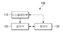
도 1은 본 발명의 일 실시 예에 따른 플렉서블 디스플레이 장치의 구성을 나타내는 블럭도이다. 도 1에 따르면, 플렉서블 디스플레이 장치(100)는 디스플레이부(110), 감지부(120) 및 제어부(130)를 포함한다.1 is a block diagram illustrating a configuration of a flexible display device according to an embodiment of the present invention. Referring to FIG. 1, the
도 1의 플렉서블 디스플레이 장치(100)는 스마트폰과 같은 휴대폰, PMP, PDA, 태블릿 PC, 네비게이션 등과 같이 휴대 가능하며 디스플레이 기능을 갖춘 다양한 유형의 장치로 구현될 수 있다. 또한, 플렉서블 디스플레이 장치(100)는 휴대용 장치뿐만 아니라, 모니터, TV, 키오스크 등 거치형 장치로 구현될 수도 있다.The
디스플레이부(110)는 다양한 화면을 디스플레이한다. 구체적으로, 디스플레이부(110)는 이미지, 동영상, 텍스트, 음악 등과 같은 컨텐츠의 재생 화면 또는 실행 화면 및, 각종 UI(User Interface) 화면을 디스플레이할 수 있다. .The
한편, 디스플레이부(110)를 포함한 플렉서블 디스플레이 장치(100)는 벤딩 가능한 특성을 가진다. 이에 따라, 디스플레이부(110)는 벤딩이 가능할 수 있는 구조 및 재질로 제작되어야 한다. 이하에서는 첨부된 도 2를 참조하여 디스플레이부(110)의 세부 구성을 설명하도록 한다.Meanwhile, the
도 2는 본 발명의 일 실시 예에 따른 플렉서블 디스플레이 장치를 구성하는 디스플레이부의 기본 구조를 설명하기 위한 도면이다. 도 2에 따르면, 디스플레이부(110)는 기판(111), 구동부(112), 디스플레이 패널(113) 및 보호층(114)을 포함한다.2 is a diagram illustrating a basic structure of a display unit constituting a flexible display device according to an embodiment of the present invention. Referring to FIG. 2, the
플렉서블 디스플레이 장치(100)는 기존의 평판 디스플레이 장치의 디스플레이 특성을 그대로 유지하면서 종이와 같이 휘어지거나, 구부려지거나, 접혀지거나, 또는 말릴 수 있는 장치를 의미한다. 따라서, 플렉서블 디스플레이 장치(100)는 유연한 기판 위에 제작되어야 한다.The
구체적으로, 기판(111)은 외부 압력에 의해 변형될 수 있는 플라스틱 기판(가령, 고분자 필름)으로 구현될 수 있다.Specifically, the
플라스틱 기판은 기초 소재(base film)에 배리어 코팅(barrier coating)이 양면으로 처리된 구조를 갖는다. 기초 소재의 경우, PI(Polyimide), PC(Polycarbonite), PET(Polyethyleneterephtalate), PES(Polyethersulfone), PEN(Polythylenenaphthalate), FRP(Fiber Reinforced Plastic) 등의 다양한 수지로 구현될 수 있다. 그리고, 배리어 코팅은 기초 소재에서 서로 대향되는 면에 수행되며, 유연성을 유지하기 위해 유기막 또는 무기막이 이용될 수 있다.The plastic substrate has a structure in which a barrier coating is treated on both sides of a base film. In the case of the basic material, it may be implemented with various resins such as PI (Polyimide), PC (Polycarbonite), PET (Polyethyleneterephtalate), PES (Polyethersulfone), PEN (Polythylenenaphthalate), FRP (Fiber Reinforced Plastic). In addition, the barrier coating is performed on surfaces facing each other in the base material, and an organic film or an inorganic film may be used to maintain flexibility.
한편, 기판(111)은 플라스틱 기판 외에도 유리 박막(thin glass) 또는 금속 박막(metal foil) 등과 같이 플렉서블한 특성을 갖는 소재가 사용될 수도 있다.Meanwhile, as the
구동부(112)는 디스플레이 패널(113)을 구동시키는 기능을 한다. 구체적으로, 구동부(112)는 디스플레이 패널(113)을 구성하는 복수의 화소에 구동 전압을 인가하며, a-si TFT, LTPS(low temperature poly silicon) TFT, OTFT(organic TFT) 등으로 구현될 수 있다.The
한편, 구동부(112)는 디스플레이 패널(113)의 구현 형태에 따라 다양한 형태로 구현될 수 있다. 일 예로, 디스플레이 패널(113)은 복수의 화소 셀로 이루어진 유기 발광체 및 그 유기 발광체의 양면을 덮는 전극층으로 이루어질 수 있다. 이 경우, 구동부(112)는 디스플레이 패널(113)의 각 화소 셀에 대응되는 복수의 트랜지스터를 포함할 수 있다. 제어부(130)는 각 트랜지스터의 게이트로 전기 신호를 인가하여, 트랜지스터에 연결된 화소 셀을 발광시킨다. 이에 따라, 영상이 표시될 수 있다.Meanwhile, the
또는, 디스플레이 패널(113)은 유기발광다이오드(OLED) 외에도 EL, EPD(electrophoretic display), ECD(electrochromic display), LCD(liquid crystal disply), AMLCD, PDP(Plasma display Panel) 등으로 구현될 수도 있다. 다만, LCD의 경우, 자체적으로 발광할 수 없다는 점에서 별도의 백라이트가 요구된다. 백라이트가 사용되지 않는 LCD의 경우에는 주변 광을 이용한다. 따라서, 백라이트 없이 LCD 디스플레이 패널(113)을 사용하기 위해서는 광량이 많은 야외 환경과 같은 조건이 충족되어야 한다.Alternatively, the
보호층(114)은 디스플레이 패널(113)을 보호하는 기능을 한다. 예를 들어, 보호층(114)에는 ZrO, CeO2, Th O2 등의 재료가 이용될 수 있다. 보호층(114)은 투명한 필름 형태로 제작되어 디스플레이 패널(113) 표면 전체를 덮을 수 있다.The
한편, 도 2에 도시된 바와 달리 디스플레이부(110)는 전자 종이로 구현될 수도 있다. 전자 종이는 종이에 일반적인 잉크의 특징을 적용한 디스플레이로서, 반사광을 사용하는 점이 일반 평판 디스플레이와는 다른 점이다. 한편, 전자 종이는 트위스트 볼을 이용하거나 캡슐을 이용한 전기영동을 이용하여 그림 또는 문자를 변경할 수 있다.Meanwhile, unlike shown in FIG. 2, the
한편, 디스플레이부(110)가 투명한 재질의 구성요소로 이루어지는 경우, 벤딩이 가능하면서 투명한 성질을 가지는 플렉서블 디스플레이 장치(100)로도 구현될 수 있다. 가령, 기판(111)은 투명한 성질을 가지는 플라스틱과 같은 폴리머 재료로 구현되고, 구동부(112)가 투명 트랜지스터로 구현되며 디스플레이 패널(113)이 투명 유기 발광층 및 투명 전극으로 구현되는 경우에는, 투명성을 가질 수 있다.Meanwhile, when the
투명 트랜지스터란 기존 박막 트랜지스터의 불투명한 실리콘을 투명한 아연산화물, 산화 티타늄 등과 같은 투명 물질로 대체하여 제작한 트랜지스터를 의미한다. 또한, 투명 전극은 ITO(indium tin oxide)나 그래핀과 같은 신소재가 사용될 수도 있다. 그래핀이란 탄소원자가 서로 연결돼 벌집 모양의 평면 구조를 이루며 투명한 성질을 가지는 물질을 의미한다. 그 밖에, 투명 유기 발광 층도 다양한 재료로 구현될 수 있다.The transparent transistor refers to a transistor manufactured by replacing the opaque silicon of the existing thin film transistor with a transparent material such as transparent zinc oxide and titanium oxide. In addition, new materials such as indium tin oxide (ITO) or graphene may be used for the transparent electrode. Graphene refers to a material having a transparent property with carbon atoms connected to each other to form a honeycomb-shaped planar structure. In addition, the transparent organic light emitting layer may also be implemented with various materials.
한편, 상술한 바와 같이, 디스플레이부(110)는 외부 압력에 의해 벤딩되어 그 형태가 변형될 수 있으며, 플렉서블 디스플레이 장치(100)는 도 3 내지 도 5에 도시된 바와 같이 다양한 방식으로 벤딩을 감지할 수 있다.Meanwhile, as described above, the
도 3 내지 도 5는 본 발명의 일 실시 예에 따라 플렉서블 디스플레이 장치가 벤딩을 감지하는 방법의 일 예를 설명하기 위한 도면들이다.3 to 5 are diagrams for explaining an example of a method of detecting bending by a flexible display device according to an embodiment of the present invention.
감지부(120)는 디스플레이부(110)의 벤딩을 감지한다. 여기에서, 벤딩(bending)이란, 디스플레이부(110)가 구부러지는 상태를 의미한다. 이를 위해, 감지부(120)는 디스플레이부(110) 전면이나 후면과 같은 하나의 표면에 배치된 벤드 센서(bend sensor) 또는 양면 모두에 배치된 벤드 센서를 포함할 수 있다.The
여기에서, 벤드 센서란, 그 자체로 구부러질 수 있으며, 구부러지는 정도에 따라 저항값이 달라지는 특성을 가지는 센서를 의미한다. 벤드 센서는 광섬유 벤딩 센서나, 압력 센서, 스트레인 게이지(strain gauge) 등과 같이 다양한 형태로 구현될 수 있다.Here, the bend sensor refers to a sensor that can be bent by itself and has a characteristic in which a resistance value varies depending on the degree of bending. The bend sensor may be implemented in various forms such as an optical fiber bending sensor, a pressure sensor, or a strain gauge.
도 3은 본 발명의 일 실시 예에 따른 벤드 센서의 배치 형태를 설명하기 위한 도면이다.3 is a diagram illustrating an arrangement form of a bend sensor according to an embodiment of the present invention.
도 3(a)는 복수 개의 바 형태의 벤드 센서들이 가로 방향 및 세로 방향으로 디스플레이부(110)에 배치되어 격자 형태를 이룬 예를 나타낸다. 구체적으로, 벤드 센서는 제1 방향으로 나열된 벤드 센서(11-1 내지 11-5) 및 제1 방향에 수직한 제2 방향으로 나열된 벤드 센서(12-1 내지 12-5)를 포함한다. 각 벤드 센서들은 서로 일정한 간격만큼 이격 배치될 수 있다.3(a) shows an example in which a plurality of bar-shaped bend sensors are arranged on the
한편, 도 3(a)에서는 가로 및 세로 방향 각각으로 5 개씩 벤드 센서(11-1 내지 11-5, 12-1 내지 12-5)가 배치되는 것으로 도시하였지만 이는 일 예에 불과하며, 벤드 센서의 개수 및 길이 등은 디스플레이부(110)의 크기 등에 따라 변경될 수 있음은 물론이다. 이와 같이, 벤드 센서가 가로 및 세로 방향으로 배치되는 것은 디스플레이부(110)의 전역에서 이루어지는 벤딩을 감지하기 위해서이므로, 일부분만 플렉서블한 특성을 가지거나, 일부분에 대해서만 벤딩을 감지할 필요가 있는 장치인 경우에는, 해당 부분에만 벤드 센서가 배치될 수도 있다.Meanwhile, in FIG. 3(a), five bend sensors 11-1 to 11-5 and 12-1 to 12-5 are arranged in each of the horizontal and vertical directions, but this is only an example, and the bend sensor It goes without saying that the number and length of the
또한, 도 3(a)와 같이 벤드 센서가 디스플레이부(110)의 전면에 내장될 수 있으나 이는 일 예에 불과하며, 벤드 센서는 디스플레이부(110)의 후면에 내장될 수도 있고, 양면 모두에 내장될 수도 있다.In addition, as shown in FIG. 3(a), the bend sensor may be built in the front of the
또한, 벤드 센서의 형태, 개수 및 배치 위치도 다양하게 변경될 수 있다. 예를 들어, 디스플레이부(110)에는 하나의 벤드 센서 또는 복수 개의 벤드 센서가 결합될 수 있다. 여기서, 하나의 벤드 센서는 하나의 벤딩 데이터를 감지하는 것일 수도 있으나, 하나의 벤드 센서가 복수의 벤딩 데이터를 감지하는 복수의 센싱 채널을 갖는 것일 수도 있다.In addition, the shape, number, and arrangement position of bend sensors may be variously changed. For example, one bend sensor or a plurality of bend sensors may be coupled to the
도 3(b)는 하나의 벤드 센서를 디스플레이부(110)의 일 면에 배치된 일 예를 나타낸다. 도 3(b)에 도시된 바와 같이, 벤드 센서(21)는 디스플레이부(110)의 전면에서 원 형태로 배치될 수 있다. 하지만, 이는 일 예에 불과하며 디스플레이부(110)의 후면에 배치될 수도 있고, 사각형 등과 같은 다양한 다각형을 이루는 폐곡선 형태로 구현될 수 있음은 물론이다.3(b) shows an example in which one bend sensor is disposed on one surface of the
도 3(c)는 두 개의 벤드 센서가 서로 교차되도록 배치된 실시 예를 나타낸다. 도 3(c)에 따르면, 제1 벤드 센서(21)는 디스플레이부(110)의 제1 면 상에서 제1 대각선 방향으로 배치되고, 제2 벤드 센서(22)는 제2 면 상에서 제2 대각선 방향으로 배치된다.3(c) shows an embodiment in which two bend sensors are disposed to cross each other. Referring to FIG. 3C, the
한편, 상술한 다양한 실시 예들에서는 라인 형태의 벤드 센서들이 사용되는 경우를 도시하였으나, 감지부(120)는 스트레인 게이지를 복수 개 사용하여 벤딩을 감지할 수도 있다.Meanwhile, in the above-described various embodiments, a case in which line-shaped bend sensors are used is illustrated, but the
도 3(d)는 디스플레이부(110)에 복수의 스트레인 게이지가 배치된 도면을 나타낸다. 스트레인 게이지는 가해지는 힘의 크기에 따라 저항이 크게 변하는 금속 또는 반도체를 이용하여, 그 저항치 변화에 따라 측정 대상물의 표면의 변형을 감지하는 것이다. 일반적으로 금속과 같은 재료는 외부로부터의 힘에 따라 길이가 늘어나면 저항치가 증가하고, 길이가 줄어들면 저항치가 감소하는 특성이 있다. 따라서, 저항치 변화를 감지하면 디스플레이부(110)의 벤딩을 감지할 수 있다.3(d) shows a diagram in which a plurality of strain gauges are disposed on the
한편, 도 3(d)에 따르면, 디스플레이부(110)의 가장 자리 영역에는 복수의 스트레인 게이지들이 배치된다. 스트레인 게이지의 개수는 디스플레이부(110)의 사이즈나, 형태, 기 설정된 벤딩 감지, 해상도 등에 따라 달라질 수 있다.Meanwhile, according to FIG. 3D, a plurality of strain gauges are disposed in the edge area of the
이하에서는, 감지부(120)가 격자 형태로 배치된 벤드 센서 또는 스트레인 게이지를 이용하여 디스플레이부(110)의 벤딩을 감지하는 방법을 설명하도록 한다.Hereinafter, a method of detecting the bending of the
벤드 센서는 전기 저항을 이용하는 전기 저항식 센서 또는 광섬유의 변형률을 이용하는 마이크로 광섬유 센서 형태로 구현될 수 있는데, 이하에서는 설명의 편의를 위하여 벤드 센서가 전기 저항식 센서로 구현되는 경우를 상정하여 설명하도록 한다.The bend sensor may be implemented in the form of an electrical resistance sensor using electrical resistance or a micro optical fiber sensor using strain of an optical fiber. Hereinafter, for convenience of explanation, it is assumed that the bend sensor is implemented as an electrical resistance sensor. do.
도 4는 본 발명의 일 실시 예에서, 플렉서블 디스플레이 장치에서 벤딩을 감지하는 방법을 설명하기 위한 도면이다.FIG. 4 is a diagram illustrating a method of detecting bending in a flexible display device according to an exemplary embodiment of the present invention.
디스플레이부(110)가 벤딩되면, 디스플레이부(110)의 일 면 또는 양면에 배치된 벤드 센서도 함께 구부러지며, 벤드 센서는 가해지는 장력의 세기에 대응되는 저항값을 출력한다. 즉, 벤드 센서는 외부에서 가해지는 힘에 의해 늘어나게 되면, 늘어나는 정도에 대응되는 저항값을 출력하게 된다.When the
따라서, 감지부(120)는 벤드 센서에 인가되는 전압의 크기 또는 벤드 센서를 흐르는 전류의 크기를 이용하여 벤드 센서의 저항값을 감지하고, 감지된 저항값의 크기를 이용하여 디스플레이부(110)의 벤딩을 감지할 수 있다. 즉, 감지부(120)는 벤드 센서가 원 상태에서와는 다른 저항값을 출력하는 경우 디스플레이부(110)가 벤딩된 것으로 감지할 수 있다.Accordingly, the
예를 들어, 도 4(a)와 같이 디스플레이부(110)가 가로 방향으로 벤딩되면, 디스플레이부(110)의 전면에 내장된 벤드 센서(41-1 내지 41-5) 또한 구부러지고, 가해지는 장력의 크기에 따른 저항값을 출력한다.For example, when the
이 경우, 장력의 세기는 벤딩 정도에 비례하여 커지게 된다. 가령, 도 4(a)와 같은 형태로 디스플레이부(110)가 벤딩되면, 중심 영역의 벤딩 정도가 가장 크게 된다. 따라서, 중심 영역인 벤드 센서(41-1)의 a3 지점, 벤드 센서(41-2)의 b3 지점, 벤드 센서(41-3)의 c3 지점, 벤드 센서(41-4)의 d3 지점, 벤드 센서(41-5)의 e3 지점에 가장 큰 장력이 작용하게 되고, 이에 따라, 각 벤드 센서(41-1 내지 41-5)는 a3 지점, b3 지점, c3 지점, d3 지점 및 e3 지점에서 가장 큰 저항값을 가지게 된다.In this case, the strength of the tension increases in proportion to the degree of bending. For example, when the
반면, 바깥 방향으로 갈수록 벤딩 정도가 약해진다. 이에 따라, 벤드 센서(41-1)는 a3 지점을 기준으로 좌측 및 우측 방향으로 갈수록 a3 지점보다 작은 저항값을 가지게 되며, 벤딩이 이루어지지 않은 a1 지점과 그 좌측 영역, a5 지점과 그 우측 영역은 벤딩되기 전과 동일한 저항값을 가지게 된다. 이는 다른 벤드 센서들(41-2 내지 41-5)의 경우도 마찬가지로 적용된다.On the other hand, the degree of bending becomes weaker as it goes outward. Accordingly, the bend sensor 41-1 has a resistance value smaller than the point a3 as it goes to the left and right with respect to the point a3, and the point a1 and its left area, and the point a5 and its right area where bending is not performed. Has the same resistance value as before bending. This also applies to the other bend sensors 41-2 to 41-5.
한편, 감지부(120)는 벤드 센서의 저항값 변화가 감지된 지점들간의 관계를 기초로, 벤딩 영역의 위치, 벤딩 영역의 크기, 벤딩 영역의 개수, 벤딩 라인의 크기, 벤딩 라인의 위치, 벤딩 라인의 개수, 벤딩 라인의 방향, 벤딩 횟수 등을 감지할 수 있다.On the other hand, the
벤딩 영역은 디스플레이부(110)가 휘어져서 구부러진 영역을 의미한다. 구체적으로, 디스플레이부(110)의 벤딩에 의해 벤드 센서가 함께 구부러지게 되므로, 벤딩 영역은, 원 상태에서와는 다른 저항값을 출력하는 벤드 센서가 배치된 모든 지점으로 정의될 수 있다. 한편, 저항값이 변하지 않은 영역은 벤딩이 이루어지지 않은 플랫(flat) 영역으로 정의할 수 있다.The bending area means an area where the
감지부(120)는 저항값 변화가 감지된 지점들 사이의 거리가 기설정된 거리 이내이면 저항값을 출력하는 지점들을 하나의 벤딩 영역으로 감지한다. 반면, 감지부(120)는 저항값 변화가 감지된 지점들 중 그 사이의 거리가 기설정된 거리 이상으로 이격된 지점이 존재하면, 이들 지점을 기준으로 서로 다른 벤딩 영역으로 구분할 수 있다.When the distance between the points at which the resistance value change is detected is within a preset distance, the
상술한 바와 같이, 도 4(a)에서, 벤드 센서(41-1)의 a1 지점부터 a5 지점까지, 벤드 센서(41-2)의 b1 지점부터 b5 지점까지, 벤드 센서(41-3)의 c1 지점부터 c5 지점까지, 벤드 센서(41-4)의 d1 지점부터 d5 지점까지, 벤드 센서(41-5)의 e1 지점부터 e5 지점까지 원 상태에서와는 다른 저항값을 가지게 된다. 이 경우, 각 벤드 센서(41-1 내지 41-5)에서 저항값 변화가 감지된 지점들은 서로 기 설정된 거리 이내에 위치하여 연속적으로 배치된다.As described above, in FIG. 4(a), from a1 point to a5 point of the bend sensor 41-1, from a point b1 to a point b5 of the bend sensor 41-2, the bend sensor 41-3 From the point c1 to the point c5, from the point d1 to the point d5 of the bend sensor 41-4, and from the point e1 to the point e5 of the bend sensor 41-5, the resistance values are different from those in the original state. In this case, the points at which the resistance value change is detected by each of the bend sensors 41-1 to 41-5 are located within a preset distance from each other and are continuously arranged.
따라서, 감지부(120)는 벤드 센서(41-1)에서 a1 지점부터 a5 지점까지, 벤드 센서(41-2)에서 b1 지점부터 b5 지점까지, 벤드 센서(41-3)에서 c1 지점부터 c5 지점까지, 벤드 센서(41-4)에서 d1 지점부터 d5 지점까지, 벤드 센서(41-5)에서 e1 지점부터 e5 지점까지를 모두 포함하는 영역(42)을 하나의 벤딩 영역으로 감지할 수 있다.Accordingly, the
한편, 벤딩 영역은 벤딩 라인을 포함할 수 있다. 벤딩 라인이란 각 벤딩 영역에서 가장 큰 저항값이 검출된 지점들을 연결하는 라인으로 정의될 수 있다.Meanwhile, the bending area may include a bending line. The bending line may be defined as a line connecting points where the largest resistance value is detected in each bending area.
가령, 도 4(a)의 경우, 벤딩 센서(41-1)에서 가장 큰 저항값을 출력하는 a3 지점, 벤드 센서(41-2)에서 가장 큰 저항값을 출력하는 b3 지점, 벤드 센서(41-3)에서 가장 큰 저항값을 출력하는 c3 지점, 벤드 센서(41-4)에서 가장 큰 저항값을 출력하는 d3 지점, 벤드 센서(41-5)에서 가장 큰 저항값을 출력하는 e3 지점을 연결하는 라인(43)을 벤딩 라인으로 정의할 수 있다. 도 4(a)에서는 벤딩 라인이 디스플레이 표면의 중앙 영역에서 세로 방향으로 형성된 상태를 나타낸다. 이와 같은 방법으로, 감지부(120)는 디스플레이부(110)의 벤딩에 의해 형성된 벤딩 라인을 감지할 수 있다.For example, in the case of FIG. 4(a), the point a3 outputs the largest resistance value from the bending sensor 41-1, the point b3 outputs the largest resistance value from the bend sensor 41-2, and the bend sensor 41 Point c3 where the largest resistance value is output from -3), point d3 where the largest resistance value is output from the bend sensor (41-4), and point e3 where the largest resistance value is output from the bend sensor (41-5). The connecting
한편, 도 4(a)는 디스플레이부(110)가 가로 방향으로 벤딩된 경우를 설명하기 위한 것이라는 점에서, 격자 형태의 벤드 센서 중 가로 방향으로 배치된 벤드 센서만을 도시하였다. 즉, 감지부(120)는 세로 방향으로 배치된 벤드 센서를 통해, 가로 방향으로 벤딩될 때와 동일한 방법을 이용하여 디스플레이부(110)가 세로 방향으로 벤딩되는 것을 감지할 수 있음은 물론이다. 뿐만 아니라, 대각선 방향으로 디스플레이부(110)가 벤딩되면 장력은 가로 및 세로 방향으로 배치된 벤드 센서들에 모두에 가해지므로, 감지부(120)는 가로 및 세로 방향으로 배치된 벤드 센서의 출력값에 기초하여 디스플레이부(110)가 대각선 방향으로 벤딩되는 것을 감지할 수 있다.Meanwhile, since FIG. 4(a) is for explaining a case where the
다른 한편, 감지부(120)는 스트레인 게이지를 이용하여 디스플레이부(110)의 벤딩을 감지할 수도 있다.On the other hand, the
구체적으로, 디스플레이부(110)가 벤딩되면, 디스플레이부(110)의 가장자리 영역에 배치된 스트레인 게이지에 힘이 작용하게 되며, 스트레인 게이지는 가해지는 힘의 크기에 따라 서로 다른 저항값을 출력하게 된다. 이에 따라, 감지부(120)는 스트레인 게이지의 출력값에 기초하여 디스플레이부(110)의 벤딩을 감지할 수 있다.Specifically, when the
예를 들어, 도 4(b)와 같이, 디스플레이부(110)가 가로 방향으로 벤딩되면, 디스플레이부(110)의 전면에 내장된 복수의 스트레인 게이지들 중 벤딩된 영역에 배치된 스트레인 게이지(51-p,..., 51-p+5, 51-r,..., 51-r+5)에 힘이 가해지고, 가해지는 힘의 크기에 따른 저항값을 출력하게 된다. 이에 따라, 감지부(120)는 원 상태에서와는 다른 저항값을 출력하는 스트레인 게이지가 위치한 지점들을 모두 포함한 영역(52)을 하나의 벤딩 영역으로 감지한다.For example, as shown in FIG. 4B, when the
그리고, 감지부(120)는 벤딩 영역 내에서 원 상태에서와 차이가 큰 저항값을 출력하는 적어도 2개의 스트레인 게이지를 연결한 라인을 벤딩 라인으로 감지할 수 있다. 즉, 감지부(120)는 디스플레이부(110)의 벤딩에 따라, 가장 큰 힘이 가해지는 적어도 2개의 스트레인 게이지 또는 가장 큰 힘과 다음으로 큰 힘이 가해지는 적어도 2개의 스트레인 게이지를 연결한 라인을 벤딩 라인으로 감지할 수 있다.In addition, the
예를 들어, 도 4(b)와 같이, 디스플레이부(110)가 가로 방향으로 벤딩되어, 원 상태에서와 차이가 큰 저항값을 출력하는 제1 스트레인 게이지(51-p+2)와 제2 스트레인 게이지(51-r+3)를 연결한 라인을 벤딩 라인으로 감지할 수 있다.For example, as shown in FIG. 4(b), the
한편, 상술한 실시 예에서는 디스플레이부(110)의 전면에 스트레인 게이지(51-1,51-2,...)가 내장된 것으로 도시하였다. 이와 같이, 스트레인 게이지(51-1,51-2,...)가 디스플레이부(110)의 전면에 배치되는 것은, 디스플레이부(110)가 Z+ 방향으로 벤딩될 때의 벤딩을 감지하기 위한 것이다.Meanwhile, in the above-described embodiment, it is illustrated that strain gauges 51-1, 51-2, ... are built in the front surface of the
한편, 디스플레이부(110)가 Z- 방향으로 벤딩되는 것을 감지하기 위해, 스트레인 게이지는 디스플레이부(110)의 후면에 내장될 수도 있다. 하지만, 이는 일 예일 뿐, 스트레인 게이지는 디스플레이부(110)의 일 면에 배치되어 Z+ 방향 및 Z- 방향으로의 벤딩을 감지하도록 구현될 수 있음은 물론이다.Meanwhile, in order to detect that the
한편, 감지부(120)는 디스플레이부(110)가 벤딩되는 정도 즉, 벤딩 각도를 감지할 수 있다. 여기에서, 벤딩 각도는 디스플레이부(110)가 플랫한 상태일 때와 벤딩에 의해 구부러진 상태가 이루는 각도를 의미할 수 있다.Meanwhile, the
도 5는 본 발명의 일 실시 예에 따라 플렉서블 디스플레이 장치가 디스플레이부의 벤딩 각도를 판단하는 방법을 설명하기 위한 도면이다.5 is a diagram illustrating a method of determining a bending angle of a display unit by a flexible display device according to an embodiment of the present invention.
감지부(120)는 디스플레이부(110)의 벤딩 각도를 감지할 수 있다. 이를 위해, 플렉서블 디스플레이 장치(100)는 디스플레이부(110)의 벤딩 각도별로 벤딩 라인에서 출력되는 저항값들을 기저장할 수 있다. 이에 따라, 감지부(120)는 디스플레이부(110)의 벤딩 시, 벤딩 라인에 위치한 벤드 센서 또는 스트레인 게이지에서 출력되는 저항값의 크기를 기저장된 저항값과 비교하여, 감지된 저항값의 크기에 매칭되는 벤딩 각도를 판단할 수 있다.The
예를 들어, 도 5에 도시된 바와 같이, 디스플레이부(110)가 벤딩되면 벤딩 라인에 위치한 벤드 센서 지점(a4)에서 가장 큰 저항값이 출력된다. 이때, 감지부(120)는 벤딩 각도별로 기저장된 저항들을 이용하여, a4 지점에서 출력되는 저항값에 매칭되는 벤딩 각도(θ)를 판단할 수 있다.For example, as illustrated in FIG. 5, when the
한편, 상술한 바와 같이, 디스플레이부(110)의 벤딩 방향은 Z+ 방향 또는 Z- 방향으로 구분될 수 있다. 한편, 감지부(120)는 디스플레이부(110)의 벤딩 방향을 감지할 수 있으며, 보다 구체적인 설명을 위해 도 6 및 7을 참조한다.Meanwhile, as described above, the bending direction of the
도 6은 본 발명의 일 실시 예에 따른 중첩된 벤드 센서를 이용하여 벤딩 방향을 감지하는 방법에 대하여 설명하기 위한 도면이다.6 is a diagram for describing a method of detecting a bending direction using an overlapped bend sensor according to an embodiment of the present invention.
감지부(120)는 디스플레이부(110)의 벤딩 방향을 감지할 수 있다. 이를 위해, 감지부(120)는 다양한 방식으로 배치된 벤드 센서를 포함할 수 있다.The
예를 들어, 도 6(a)과 같이, 감지부(120)는 디스플레이부(110)의 일 측에 중첩된 두 개의 벤드 센서(71, 72)를 포함할 수 있다. 이 경우, 한쪽 방향으로 벤딩이 이루어지게 되면, 벤딩이 이루어진 지점에서 상위 벤드 센서(71) 및 하위 벤드 센서(72)의 저항값이 다르게 검출된다. 따라서, 동일 지점에서의 두 벤드 센서(71, 72)의 저항값을 비교하면, 벤딩 방향을 알 수 있다. 여기에서, 벤딩 방향은 Z+ 방향과 Z- 방향으로 구분될 수 있으며, 디스플레이부(110)를 2차원 상의 x-y 평면으로 가정할 때, 벤딩된 디스플레이부(110)의 일 영역이 Z 축 상에서 향하는 방향으로 정의될 수 있다.For example, as shown in FIG. 6A, the
구체적으로, 도 6(b)와 같이 디스플레이부(110)의 우측 영역이 Z+ 방향으로 벤딩되면, 벤딩 라인에 해당하는 A 지점에서, 위쪽 벤드 센서(71)보다 아래쪽 벤드 센서(72)에 더 큰 세기의 장력이 가해지게 된다. 이와 반대로, 디스플레이부(110)의 우측 영역이 Z- 방향으로 벤딩되면, 위쪽 벤드 센서(71)에서 아래쪽 벤드 센서(72)보다 더 큰 세기의 장력이 가해지게 된다.Specifically, when the right area of the
따라서, 감지부(120)는 두 벤드 센서(71, 72)에서 A 지점에 해당하는 저항값을 비교하여, 디스플레이부(110)의 가장자리 영역에 대한 벤딩 방향을 감지할 수 있다. 즉, 감지부(120)는 중첩된 두 개의 벤드 센서 중 하위 벤드 센서에서 출력되는 저항값이 동일한 지점에서 상위 벤드 센서에서 출력되는 저항값보다 큰 경우, Z+ 방향으로 벤딩되는 것으로 감지할 수 있다. 또한, 감지부(120)는 중첩된 두 개의 벤드 센서 중 상위 벤드 센서에서 출력되는 저항값이 동일한 지점에서 하위 벤드 센서에서 출력되는 저항값보다 큰 경우 Z- 방향으로 벤딩되는 것으로 감지할 수 있다.Accordingly, the
한편, 상술한 예에서는 디스플레이부(110)의 우측 영역이 벤딩되는 경우, 벤딩 방향을 감지하는 방법을 설명하였으나 이는 일 예에 불과하다. 즉, 디스플레이부(110)의 좌측 영역, 상측 영역, 하측 영역 등 디스플레이부(110)의 가장자리 영역이 벤딩되는 경우에도 감지부(120)는 동일한 방법으로 디스플레이부(110)의 벤딩 방향을 감지할 수 있다.Meanwhile, in the above-described example, a method of detecting the bending direction when the right area of the
또한, 디스플레이부(110)의 중심 영역이 벤딩된 경우에도, 감지부(120)는 디스플레이부(110)의 벤딩 방향을 감지할 수 있다. 예를 들어, 디스플레이부(110)의 중심 영역이 벤딩될 때, 중첩된 두 개의 벤드 센서 중 상위 벤드 센서에서 출력되는 저항값이 동일한 지점에서 하위 벤드 센서에서 출력되는 저항값보다 큰 경우, 감지부(120)는 디스플레이부(110)의 중심 부분이 Z+ 방향으로 볼록하게 벤딩된 것으로 감지할 수 있다. 이와 반대로, 디스플레이부(110)의 중심 영역이 벤딩될 때, 중첩된 두 개의 벤드 센서 중 하위 벤드 센서에서 출력되는 저항값이 동일한 지점에서 상위 벤드 센서에서 출력되는 저항값보다 큰 경우, 감지부(120)는 디스플레이부(110)의 중심 부분이 Z- 방향으로 볼록하게 벤딩된 것으로 감지할 수 있다.In addition, even when the central region of the
한편, 도 6(a) 및 도 6(b)에서는 두 벤드 센서가 디스플레이부(110)의 일측에서 서로 중첩되어 배치된 상태를 도시하였으나, 도 6(c)와 같이 감지부(120)는 디스플레이부(110)의 양면에 배치된 벤드 센서를 포함할 수도 있다.Meanwhile, in FIGS. 6(a) and 6(b), two bend sensors overlap each other on one side of the
도 6(c)는 두 벤드 센서(73, 74)가 디스플레이부(110)의 양면에 배치된 상태를 나타낸다.6(c) shows a state in which two
도 6(c)의 경우에도, 디스플레이부(110)가 벤딩될 때 벤딩 방향에 따라 디스플레이부(110)의 제1 면에 배치된 벤드 센서(73)와 제2 면에 배치된 벤드 센서(74)는 동일한 지점에서 서로 다른 저항값을 출력하게 된다. 구체적으로, 디스플레이부(110)의 가장자리 영역이 Z- 방향으로 벤딩되면 벤딩 라인에 해당하는 지점에서 제1 면에 배치된 벤드 센서(73)에 더 큰 세기의 장력이 가해지게 되며, 이와 반대로, 디스플레이부(110)의 가장자리 영역이 Z+ 방향으로 벤딩되면 벤딩 라인에 해당하는 지점에서 제2 면에 배치된 벤드 센서(74)에 더 큰 세기의 장력이 가해지게 된다.In the case of FIG. 6C as well, when the
따라서, 감지부(120)는 두 벤드 센서(73, 74)의 동일한 지점에 해당하는 저항값을 비교하여, 디스플레이부(110)의 가장자리 영역에 대한 벤딩 방향을 판단할 수 있다. 예를 들어, 감지부(120)는 디스플레이부(110)의 후면에 내장된 벤드 센서(74)에서 출력되는 저항값이 동일한 지점에서 디스플레이부(110)의 전면에 내장된 벤드 센서(73)에서 출력되는 저항값보다 큰 경우, 디스플레이부(110)의 가장자리 영역이 Z+ 방향으로 벤딩된 것으로 판단할 수 있다. 또한, 감지부(120)는 디스플레이부(110)의 전면에 내장된 벤드 센서(73)에서 출력되는 저항값이 동일한 지점에서 디스플레이부(110)의 후면에 내장된 벤드 센서(74)에서 출력되는 저항값보다 큰 경우, 디스플레이부(110)의 가장자리 영역이 Z- 방향으로 벤딩된 것으로 판단할 수 있다.Accordingly, the
한편, 상술한 예에서는 디스플레이부(110)의 좌측 또는 우측이 벤딩된 경우를 설명하였다. 다만, 디스플레이부(110)의 중심 영역이 벤딩된 경우, 감지부(120)는 디스플레이부(110)의 벤딩 방향을 감지할 수 있다. 예를 들어, 디스플레이부(110)의 중심 영역이 벤딩될 때, 디스플레이부(110)의 전면에 내장된 벤드 센서에서 출력되는 저항값이 동일한 지점에서 디스플레이부(110)의 후면에 내장된 벤드 센서에서 출력되는 저항값보다 큰 경우, 감지부(120)는 디스플레이부(110)의 중심 영역이 Z+ 방향으로 볼록하게 벤딩된 것으로 감지할 수 있다. 또한, 디스플레이부(110)의 중심 영역이 벤딩될 때, 디스플레이부(110)의 후면에 내장된 벤드 센서에서 출력되는 저항값이 동일한 지점에서 디스플레이부(110)의 전면에 내장된 벤드 센서에서 출력되는 저항값보다 큰 경우, 감지부(120)는 디스플레이부(110)의 중심 영역이 Z- 방향으로 볼록하게 벤딩된 것으로 감지할 수 있다.Meanwhile, in the above-described example, a case where the left or right side of the
이와 같이, 벤딩 방향에 따라 두 벤드 센서에서 감지되는 값은 서로 다르게 검출되며, 감지부(120)는 그 값의 검출 특성에 따라 벤딩 방향을 구분할 수 있다.In this way, values sensed by the two bend sensors are detected differently according to the bending direction, and the
한편, 도 6(a) 내지 도 6(c)에서는 두 개의 벤드 센서를 이용하여 벤딩 방향을 감지하는 것으로 설명하였으나, 디스플레이부(110)의 일 면 또는 양면에 배치된 스트레인 게이지만으로도 벤딩 방향을 구분할 수도 있다. 예를 들어, 감지부(120)는 디스플레이부(110)의 전면에 내장된 스트레인 게이지에서 원 상태와 다른 저항값이 출력되는 경우 디스플레이부(110)가 Z+ 방향으로 벤딩된 것으로 판단하고, 디스플레이부(110)의 후면에 내장된 스트레인 게이지에서 원 상태와 다른 저항값이 출력되는 경우 플렉서블 장치(100)가 Z- 방향으로 벤딩된 것으로 판단할 수 있다. 하지만, 이는 일 예일 뿐, 스트레인 게이지는 디스플레이부(110)의 일 면에 배치되어 Z+ 방향 및 Z- 방향으로의 벤딩을 감지하도록 구현될 수 있음은 물론이다.On the other hand, in Figs. 6(a) to 6(c), it has been described that the bending direction is detected using two bend sensors, but only strain gauges disposed on one or both sides of the
도 7은 본 발명의 다른 실시 예에 따른 벤딩 방향 감지 방법을 설명하기 위한 도면이다. 구체적으로, 도 7(a) 및 도 7(b)는 일 예로 가속도 센서를 이용하여 벤딩 방향을 감지하는 방법을 설명하기 위한 도면이다.7 is a diagram illustrating a method of detecting a bending direction according to another exemplary embodiment of the present invention. Specifically, FIGS. 7A and 7B are diagrams for explaining a method of detecting a bending direction using an acceleration sensor as an example.
감지부(120)는 디스플레이부(110)의 가장자리 영역에 배치된 복수의 가속도 센서를 포함할 수 있다.The
가속도 센서(즉, 중력 센서, G 센서)는 움직임 발생시 가속도 및 가속도의 방향을 측정할 수 있는 센서이다. 구체적으로는, 가속도 센서는 그 센서가 부착된 장치의 기울기에 따라 변화되는 중력 가속도에 대응되는 센싱 값을 출력한다.The acceleration sensor (ie, gravity sensor, G sensor) is a sensor that can measure acceleration and direction of acceleration when motion occurs. Specifically, the acceleration sensor outputs a sensing value corresponding to the gravitational acceleration that changes according to the tilt of the device to which the sensor is attached.
따라서, 도 7(a)와 같이, 디스플레이부(110)의 양측 가장 자리 영역에 가속도 센서(81-1, 81-2)를 각각 배치하면, 디스플레이부(110)가 벤딩될 때 가속도 센서(81-1, 81-2) 각각에서 센싱되는 출력값이 변화된다. 감지부(120)는 가속도 센서(81-1, 81-2) 각각에서 센싱되는 출력값을 이용하여 피치각(pitch angle) 및 롤각(role angle)을 연산한다. 이에 따라, 감지부(120)는 가속도 센서(81-1, 81-2) 각각에서 감지된 피치각 및 롤각의 변화 정도에 기초하여 벤딩 방향을 판단할 수 있다.Accordingly, as shown in FIG. 7(a), if the acceleration sensors 81-1 and 81-2 are respectively disposed in the edge areas on both sides of the
한편, 도 7(a)에서는 디스플레이부(110)가 전면을 기준으로 가로 방향 양 측 가장자리에 가속도 센서(81-1, 81-2)가 배치된 상태를 도시하였으나, 도 7(b)에서와 같이 세로 방향으로 배치될 수도 있다. 이 경우, 감지부(120)는 디스플레이부(110)가 세로 방향으로 벤딩되면, 세로 방향의 가속도 센서(81-3, 81-4) 각각에서 감지한 측정값에 따라 벤딩 방향을 감지할 수 있다.On the other hand, in Fig. 7(a), the
한편, 도 7(a) 및 도 7(b)는 디스플레이부(110)의 좌우측 가장자리 또는 상하측 가장자리에 가속도 센서가 배치된 상태를 도시하였으나, 가속도 센서는 상하좌우측 가장자리 모두에 배치될 수도 있고, 모서리 영역에 배치될 수도 있다.On the other hand, Figures 7(a) and 7(b) show a state in which the acceleration sensor is disposed at the left and right edges or upper and lower edges of the
한편, 상술한 가속도 센서 이외에 자이로 센서나 지자기 센서를 이용하여 벤딩 방향을 감지할 수도 있다. 자이로 센서는 회전 운동이 일어나면, 그 속도 방향으로 작용하는 코리올리의 힘을 측정하여, 각속도를 검출하는 센서이다. 자이로 센서의 측정 값에 따르면, 어느 방향으로 회전되었는지를 검출할 수 있게 되므로, 벤딩 방향을 감지할 수 있다. 지자기 센서는 2축 또는 3축 플럭스게이트를 이용하여 방위각을 감지하는 센서이다. 지자기 센서로 구현된 경우, 플렉서블 디스플레이 장치(100)의 각 가장 자리 부분에 배치된 지자기 센서는 그 가장자리 부분이 벤딩되면 위치 이동이 이루어지게 되어, 그로 인한 지자기 변화에 대응되는 전기 신호를 출력한다. 플렉서블 디스플레이 장치는 지자기 센서로부터 출력되는 값을 이용하여 요우 각(yaw angle)을 산출할 수 있다. 이에 따라, 산출된 요우각의 변화에 따라 벤딩 영역 및 벤딩 방향 등과 같은 다양한 벤딩 특성을 판단할 수 있다.Meanwhile, in addition to the above-described acceleration sensor, the bending direction may be detected using a gyro sensor or a geomagnetic sensor. The gyro sensor is a sensor that detects the angular velocity by measuring the Coriolis force acting in the direction of the rotational motion. According to the measured value of the gyro sensor, since it is possible to detect in which direction the rotation is made, the bending direction can be detected. The geomagnetic sensor is a sensor that detects the azimuth angle using a 2-axis or 3-axis fluxgate. When implemented as a geomagnetic sensor, a geomagnetic sensor disposed at each edge portion of the
이상과 같이, 감지부(120)는 다양한 방법으로 디스플레이부(110)의 벤딩을 감지할 수 있다. 상술한 센서의 구성 및 센싱 방법은 개별적으로 플렉서블 디스플레이 장치(100)에 적용될 수도 있고, 서로 조합되어 적용될 수도 있다. 다만, 상술한 실시 예에서는 감지부(120)가 디스플레이부(110)의 벤딩을 판단하는 것으로 설명하였으나, 이는 일 예에 불과하다. 즉, 제어부(130)는 감지부(120)의 감지 결과를 전달받아, 디스플레이부(110)의 벤딩을 판단할 수도 있다.As described above, the
한편, 감지부(120)는 사용자가 디스플레이부(110)의 화면을 터치하는 조작도 감지할 수 있다. 이 경우, 감지부(120)는 감압식 또는 정전식 터치 센서를 포함하여, 사용자가 디스플레이부(110)의 화면을 터치할 때 생성되는 전기 신호에 기초하여 사용자가 디스플레이부(110)를 터치한 지점의 좌표, 터치한 영역의 크기, 터치한 압력의 크기 등을 감지할 수 있다.Meanwhile, the
제어부(130)는 플렉서블 디스플레이 장치(100)의 전반적인 동작을 제어한다. 특히, 제어부(130)는 감지부(120)의 감지 결과에 기초하여 디스플레이부(110)의 벤딩을 판단할 수 있다. 즉, 제어부(130)는 벤드 센서 또는 스트레인 게이지에서 출력되는 저항값을 이용하여 디스플레이부(110)의 벤딩 여부, 벤딩 영역의 위치, 벤딩 영역의 위치, 벤딩 영역의 크기, 벤딩 영역의 개수, 벤딩 라인의 크기, 벤딩 라인의 위치, 벤딩 라인의 개수, 벤딩 방향, 벤딩 각도, 벤딩 횟수 등을 판단할 수 있다. 이에 대해서는, 도 3 내지 도 7에서 설명한바 있다는 점에서, 구체적인 중복 설명은 생략하도록 한다.The
한편, 디스플레이부(110)는 3차원 공간을 촬영한 영상 데이터를 디스플레이할 수 있다. 여기에서, 3차원 공간을 촬영한 영상 데이터는, 로드뷰 데이터를 포함할 수 있다.Meanwhile, the
구체적으로, 로드뷰 데이터는 전국 각지의 실제 거리 모습이 360°로 촬영된 파노라마 이미지로 구성되며, 촬영 골목 구석 구석까지 생생한 모습을 확인할 수 있는 지도 서비스 데이터이다. 예를 들어, 로드뷰 데이터는 카메라 앵글이 180°이상으로 촬영할 수 있게 설계된 특수 렌즈인 어안 렌즈에 의해 촬영되어 생성되거나, 미리 촬영된 수많은 이미지를 파노라마 형태로 재구성하여 생성될 수 있다. 한편, 이러한 로드뷰 데이터는 플렉서블 디스플레이 장치(100)에 기저장되어 있을 수 있거나, 네트워크를 통해 외부 서버(미도시)로부터 제공받을 수 있다. 이 경우, 플렉서블 디스플레이 장치(100)는 네트워크 통신 가능한 통신부(미도시)를 더 포함할 수 있다.Specifically, the road view data is composed of a panoramic image of a 360° shot of actual streets across the country, and is map service data that allows you to check the vivid image of every corner of the shooting alley. For example, the road view data may be photographed and generated by a fisheye lens, a special lens designed to shoot at a camera angle of 180° or more, or may be generated by reconstructing a number of pre-captured images in a panorama form. Meanwhile, such load view data may be previously stored in the
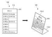
한편, 제어부(130)는 디스플레이부(110)가 벤딩되면 3차원 공간을 촬영한 영상 데이터의 일부를 벤딩 상태에 대응되도록 디스플레이할 수 있다.Meanwhile, when the
구체적으로, 제어부(130)는 디스플레이부(110)가 벤딩되어 복수의 영역으로 분할되면 복수의 분할 영역의 배치 상태에 대응되는 3차원 공간에 대한 시점을 판단하고, 판단된 시점에서 촬영된 영상 데이터를 복수의 분할 영역 각각에 디스플레이할 수 있다. 여기에서, 영상 데이터는, 로드뷰 데이터를 구성하는 복수의 파노라마 이미지 중 각 분할 영역이 바라보는 시점에서 촬영한(또는, 생성된) 파노라마 이미지일 수 있다. 즉, 제어부(130)는 디스플레이부(110)의 각 분할 영역이 바라보는 시점에서 촬영된 파노라마 이미지를 판단하고, 판단된 파노라마 이미지를 각 분할 영역에 디스플레이할 수 있다. 보다 구체적인 설명을 위해 도 8 내지 도 18을 참조하도록 한다.Specifically, when the
도 8 내지 도 18은 본 발명의 일 실시 예에 따라 벤딩된 디스플레이부에 화면을 디스플레이하는 방법을 설명하기 위한 도면들이다.8 to 18 are diagrams for explaining a method of displaying a screen on a bent display unit according to an embodiment of the present invention.
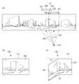
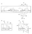
먼저, 도 8(a)는 로드뷰 데이터를 설명하기 위한 도면이다. 도 8(a)과 같이, 로드뷰 데이터는 카메라의 위치인 기준 위치(210) 및 카메라가 바라보는 촬영 방향(220)을 변수로 하여 결정된다. 여기에서, 촬영 방향(220)은 기준 위치(210)를 원점으로 하는 3차원 직교 좌표계(X, Y, Z)에서 정의되는 방향 벡터로, 로드뷰 데이터를 생성하기 위해 기준 위치(210)에서 영상을 촬영한 시점이 될 수 있다.First, FIG. 8(a) is a diagram for explaining road view data. As shown in FIG. 8(a), the road view data is determined using a
이에 따라, 제어부(130)는 촬영 방향(220)에서 촬영된 로드뷰 데이터를 검출하여 디스플레이할 수 있다. 즉, 제어부(130)는 기준 위치(210)를 시작점으로 하여 촬영 방향(220)에 대한 방향 벡터의 종점과 구(200)가 만나는 지점의 접면의 영상을 로드뷰 데이터(230)로 검출하고, 검출된 로드뷰 데이터(230)를 디스플레이할 수 있다.Accordingly, the
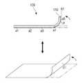
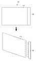
한편, 디스플레이부(110)가 벤딩되면, 벤딩에 의해 형성된 복수의 분할 영역 중 적어도 하나는 위치가 이동될 수 있다. 즉, 3차원 직교 좌표계(x, y, z) 상에서 디스플레이부(110)를 x-y 평면으로 가정할 때, 디스플레이부(110)의 적어도 하나의 영역은 벤딩에 의해 Z축의 (+) 방향으로 위치가 이동되거나 Z축의 (-) 방향으로 위치가 이동될 수 있다.Meanwhile, when the
이와 같은 경우, 제어부(130)는 디스플레이부(110)가 벤딩되기 이전에 디스플레이되던 로드뷰 데이터를 촬영한 시점을 기준으로 벤딩에 의해 위치가 이동된 영역이 바라보는 시점을 판단하고, 판단된 시점에서 촬영된 로드뷰 데이터를 검출할 수 있다.In this case, the
이를 위해, 제어부(130)는 벤딩 라인을 z축으로 하며, 벤딩 라인과 디스플레이부(110)의 교차점 중 하나를 원점으로 하는 3차원 직교 좌표계(x, y, z) 상에서, 벤딩에 의해 이동되지 않은 영역이 이루는 영역(즉, x-y 평면에 위치한 영역)과 벤딩에 의해 위치가 이동된 영역이 이루는 각도를 산출한다. 구체적으로, 제어부(130)는 디스플레이부(110)가 벤딩되면, 디스플레이부(110)의 벤딩 라인에서 출력되는 저항값을 이용하여 디스플레이부(110)의 벤딩 각도를 산출하고(도 5 참조), 산출된 벤딩 각도를 x-y 평면과 벤딩에 의해 위치가 이동된 영역이 이루는 각도로 결정할 수 있다.To this end, the
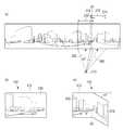
예를 들어, 도 8(b)와 같이, 디스플레이부(110)의 좌측이 Z+ 방향으로 벤딩된 경우를 가정한다. 이때, 제어부(130)는 벤딩 각도가 θ1으로 산출된 경우 벤딩에 의해 위치가 이동된 영역과 x-y 평면이 이루는 각도를 θ1으로 결정할 수 있다. 또한, 도 8(c)와 같이, 디스플레이부(110)의 우측이 Z+ 방향으로 벤딩된 경우를 가정한다. 이때, 제어부(130)는 벤딩 각도가 θ2로 산출된 경우 벤딩에 의해 위치가 이동된 영역과 x-y 평면이 이루는 각도를 θ2로 결정할 수 있다.For example, as shown in FIG. 8B, it is assumed that the left side of the
이후, 제어부(130)는 디스플레이부(110)가 벤딩되기 이전에 디스플레이되던 로드뷰 데이터를 촬영한 시점을 산출된 각도만큼 회전하여, 벤딩에 의해 위치가 이동된 영역이 바라보는 시점을 판단할 수 있다. 이때, 제어부(130)는 벤딩에 의해 위치가 이동된 영역이 x-y 평면에서 속하는 분면에 따라, 디스플레이부(110)가 벤딩되기 이전에 디스플레이되던 로드뷰 데이터를 촬영한 시점에서 산출된 각도를 더하거나 빼서, 벤딩에 의해 위치가 이동된 영역이 바라보는 시점을 판단할 수 있다.Thereafter, the
상술한 예에서, 도 8(b)와 같이, 디스플레이부(110)의 좌측이 Z+ 방향으로 벤딩되어 벤딩에 의해 위치가 이동된 영역이 x-y 평면의 x(-)y(+) 분면에 속하는 경우, 제어부(130)는 디스플레이부(110)가 벤딩되기 이전에 디스플레이되던 로드뷰 데이터를 촬영한 시점에서 산출된 각도를 빼서 벤딩에 의해 위치가 이동된 영역이 바라보는 시점을 판단할 수 있다. 즉, 도 8(a)와 같이, 제어부(130)는 디스플레이부(110)에 디스플레이되던 로드뷰 데이터를 촬영한 시점 즉, 촬영 방향(220)이 향하는 시점에서 θ1만큼 반시계방향으로 이동된 시점을 벤딩에 의해 위치가 이동된 영역이 바라보는 시점으로 판단할 수 있다. 그리고, 제어부(130)는 판단된 시점에 대응되는 촬영 방향(240)에서 촬영된 로드뷰 데이터를 검출할 수 있다. 구체적으로, 제어부(130)는 기준 위치(210)를 시작점으로 하여 촬영 방향(240)에 대한 방향 벡터의 종점과 구(200)가 만나는 지점의 접면의 영상을 로드뷰 데이터(250)로 검출할 수 있다.In the above-described example, when the left side of the
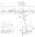
또한, 도 8(c)와 같이, 디스플레이부(110)의 우측이 Z+ 방향으로 벤딩되어 벤딩에 의해 위치가 이동된 영역이 x-y 평면의 x(+)y(+) 분면에 속하는 경우, 제어부(130)는 디스플레이부(110)가 벤딩되기 이전에 디스플레이되던 로드뷰 데이터를 촬영한 시점에서 산출된 각도를 더해서 벤딩에 의해 위치가 이동된 영역이 바라보는 시점을 판단할 수 있다. 즉, 도 8(a)와 같이, 제어부(130)는 디스플레이부(110)에 디스플레이되던 로드뷰 데이터를 촬영한 시점 즉, 촬영 방향(220)이 향하는 시점에서 θ2만큼 시계방향으로 이동된 시점을 벤딩에 의해 위치가 이동된 영역이 바라보는 시점으로 판단할 수 있다. 그리고, 제어부(130)는 판단된 시점에 대응되는 촬영 방향(260)에서 촬영된 로드뷰 데이터를 검출할 수 있다. 구체적으로, 제어부(130)는 기준 위치(210)를 시점으로 하여 촬영 방향(260)에 대한 방향 벡터의 종점과 구(200)가 만나는 지점의 접면의 영상을 로드뷰 데이터(270)로 검출할 수 있다.In addition, as shown in FIG. 8(c), when the right side of the
한편, 제어부(130)는 벤딩에 의해 위치가 이동되지 않은 영역과 벤딩에 의해 위치가 이동된 영역 각각에 로드뷰 데이터를 디스플레이할 수 있다. 보다 구체적인 설명을 위해 도 9 내지 도 16을 참조하도록 한다. 한편, 도 9 내지 도 16 도면에서는 설명의 편의를 위해 동일한 사이즈를 갖는 화면을 확대 또는 축소하여 도시하였다. 또한, 로드뷰 데이터는 복수의 파노라마 이미지들을 포함한다는 점에서, 도 9 내지 도 16에서는 설명의 편의를 위해 한 장의 파노라마 이미지를 이용하여 각 영역에서 로드뷰 데이터를 디스플레이하는 방법을 설명하도록 한다.Meanwhile, the
먼저, 제어부(130)는 벤딩에 의해 위치가 이동되지 않은 영역에는 디스플레이부(110)가 벤딩되기 이전에 디스플레이되던 로드뷰 데이터를 디스플레이한다.First, the
예를 들어, 디스플레이부(110)의 좌측이 Z+ 방향으로 θ1만큼 벤딩된 경우를 가정한다. 이 경우, 제어부(130)는 벤딩 라인을 기준으로 우측에 디스플레이되던 로드뷰 데이터를 벤딩에 의해 위치가 이동되지 않은 영역에 디스플레이할 수 있다. 즉, 제어부(130)는 벤딩에 의해 위치가 이동되지 않은 영역에 디스플레이되던 로드뷰 데이터를 그대로 디스플레이할 수 있다.For example, it is assumed that the left side of the
이 경우, 제어부(130)는 벤딩에 의해 위치가 이동된 영역에는 해당 영역에서 바라본 시점에서 촬영된 로드뷰 데이터를 디스플레이할 수 있다.In this case, the
상술한 예에서, 제어부(130)는 디스플레이부(110)가 벤딩되기 이전에 디스플레이되던 로드뷰 데이터를 촬영한 시점에서 θ1만큼 뺀 시점에서 촬영된 로드뷰 데이터를 벤딩에 의해 위치가 이동된 영역에 디스플레이할 수 있다.In the above-described example, the
즉, 도 9(a)와 같은 파노라마 이미지에서, 촬영 방향(220)에서 촬영된 로드뷰 데이터(230)가 디스플레이부(110)에 디스플레이되는 경우를 가정한다(도 9(b) 참조). 이후, 디스플레이부(110)의 좌측이 Z+ 방향으로 θ1만큼 벤딩되면, 벤딩 전에 디스플레이되던 로드뷰 데이터(230)는 벤딩 라인(10)의 우측에 디스플레이된 로드뷰 데이터(231)와 벤딩 라인(10)의 좌측에 디스플레이된 로드뷰 데이터(232)로 구분될 수 있다.That is, in the panoramic image as shown in FIG. 9(a), it is assumed that the
이에 따라, 도 9(c)와 같이, 벤딩에 의해 위치가 이동되지 않은 영역에는 벤딩 라인(10)의 우측에 디스플레이된 로드뷰 데이터(231)가 디스플레이된다. 그리고, 벤딩에 의해 위치가 이동된 영역에는 촬영 방향(220)이 향하는 시점에서 θ1만큼 반시계방향으로 이동된 시점에서 촬영된 로드뷰 데이터 즉, 촬영 방향(240)에서 촬영된 로드뷰 데이터(250)가 디스플레이된다.Accordingly, the
한편, 제어부(130)는 벤딩 이전에 디스플레이되던 로드뷰 데이터 모두를 벤딩에 의해 위치가 이동되지 않은 영역에 디스플레이할 수도 있다. 이 경우, 벤딩에 의해 위치가 이동되지 않은 영역은 디스플레이부(110)가 벤딩되기 전보다 화면 사이즈가 작아지게 되므로, 제어부(130)는 벤딩 이전에 디스플레이되던 로드뷰 데이터를 벤딩에 의해 위치가 이동되지 않은 영역의 화면 사이즈에 맞도록 조정하여 벤딩에 의해 위치가 이동되지 않은 영역에 디스플레이할 수도 있다.Meanwhile, the
예를 들어, 도 10(a) 내지 도 10(c)와 같이, 벤딩에 의해 위치가 이동되지 않은 영역에는 벤딩 이전에 디스플레이되던 로드뷰 데이터(230)가 디스플레이되고, 벤딩에 의해 위치가 이동된 영역에는 촬영 방향(220)이 향하는 시점에서 θ1만큼 반시계방향으로 이동된 시점에서 촬영된 로드뷰 데이터 즉, 촬영 방향(240)에서 촬영된 로드뷰 데이터(250)가 디스플레이될 수 있다.For example, as shown in FIGS. 10(a) to 10(c), the
한편, 제어부(130)는 벤딩에 의해 위치가 이동된 영역에 대응되는 로드뷰 데이터 중 일부만을 벤딩에 의해 위치가 이동된 영역에 디스플레이할 수도 있다.Meanwhile, the
이를 위해, 플렉서블 디스플레이 장치(100)는 기준 위치를 기준으로, 특정 시점에서 촬영된 로드뷰 데이터의 전부 또는 일부와 해당 시점에서 기설정된 각도만큼 회전된 시점에서 촬영된 로드뷰 데이터 사이에 중복되는 로드뷰 데이터에 대한 정보를 기저장할 수 있다. 이에 따라, 제어부(130)는 특정 시점에서 촬영된 로드뷰 데이터와 해당 시점에서 기설정된 각도만큼 회전된 시점에서 촬영된 로드뷰 데이터 사이에 중복되는 영상을 판단하고, 그에 대응되는 데이터를 검출할 수 있다.To this end, the
일 예로, 제어부(130)는 벤딩에 의해 위치가 이동되지 않은 영역에 디스플레이되던 로드뷰 데이터를 벤딩에 의해 위치가 이동되지 않은 영역에 그대로 디스플레이한다. 그리고, 제어부(130)는 벤딩되기 이전에 벤딩에 의해 위치가 이동되지 않은 영역에 디스플레이되던 로드뷰 데이터와 벤딩에 의해 위치가 이동된 영역에 대응되는 로드뷰 데이터 사이에서 중복되는 영상을 판단하고, 벤딩에 의해 위치가 이동된 영역에 대응되는 로드뷰 데이터에서 중복된 영상에 대한 데이터를 제거하여 벤딩에 의해 위치가 이동된 영역에 디스플레이할 수 있다.For example, the
예를 들어, 도 11(a) 내지 도 11(c)와 같이, 디스플레이부(110)가 벤딩되면, 벤딩에 의해 위치가 이동되지 않은 영역에는 벤딩 라인(10)의 우측에 디스플레이되던 로드뷰 데이터(231)가 디스플레이된다. 한편, 벤딩에 의해 위치가 이동된 영역에 대응되는 로드뷰 데이터 즉, 촬영 방향(240)에서 촬영된 로드뷰 데이터(250)와 벤딩 이전에 벤딩에 의해 위치가 이동되지 않은 영역에 디스플레이되던 로드뷰 데이터(231)는 데이터(252)만큼 중복된다. 따라서, 벤딩에 의해 위치가 이동된 영역에는 로드뷰 데이터(250)에서 중복되는 데이터(252)만큼 제거된 로드뷰 데이터(251)가 디스플레이될 수 있다.For example, as shown in FIGS. 11(a) to 11(c), when the
다른 예로, 제어부(130)는 벤딩에 의해 위치가 이동되지 않은 영역에는 벤딩 이전에 디스플레이부(110)에 디스플레이되던 로드뷰 데이터를 디스플레이한다. 그리고, 제어부(130)는 벤딩 이전에 디스플레이부(110)에 디스플레이되던 로드뷰 데이터와 벤딩에 의해 위치가 이동된 영역에 대응되는 로드뷰 데이터에서 중복되는 영상을 판단하고, 벤딩에 의해 위치가 이동된 영역에 대응되는 로드뷰 데이터에서 중복된 영상에 대한 데이터를 제거하여 벤딩에 의해 위치가 이동된 영역에 디스플레이할 수 있다.As another example, the
예를 들어, 도 12(a) 내지 도 12(c)와 같이, 디스플레이부(110)가 벤딩되면, 벤딩에 의해 위치가 이동되지 않은 영역에는 벤딩 이전에 디스플레이부(110)에 디스플레이되던 로드뷰 데이터(230)가 디스플레이된다. 한편, 벤딩에 의해 위치가 이동된 영역에 대응되는 로드뷰 데이터 즉, 촬영 방향(240)에서 촬영된 로드뷰 데이터(250)와 벤딩 이전에 디스플레이부(110)에 디스플레이되던 로드뷰 데이터(230)는 데이터(254)만큼 중복된다. 따라서, 벤딩에 의해 위치가 이동된 영역에는 로드뷰 데이터(250)에서 중복되는 데이터(254)만큼 제거된 로드뷰 데이터(253)가 디스플레이될 수 있다.For example, as shown in FIGS. 12(a) to 12(c), when the
다른 한편으로, 디스플레이부(110)의 우측이 Z+ 방향으로 θ2만큼 벤딩된 경우를 가정한다. 이 경우, 제어부(130)는 벤딩 라인을 기준으로 좌측에 디스플레이되던 로드뷰 데이터를 벤딩에 의해 위치가 이동되지 않은 영역에 디스플레이할 수 있다. 즉, 제어부(130)는 벤딩에 의해 위치가 이동되지 않은 영역에 디스플레이되던 로드뷰 데이터를 그대로 디스플레이할 수 있다.On the other hand, it is assumed that the right side of the
이 경우, 제어부(130)는 벤딩에 의해 위치가 이동된 영역에는 해당 영역에서 바라본 시점에서 촬영된 로드뷰 데이터를 디스플레이할 수 있다.In this case, the
상술한 예에서, 제어부(130)는 디스플레이부(110)가 벤딩되기 이전에 디스플레이되던 로드뷰 데이터를 촬영한 시점에서 θ2만큼 더한 시점에서 촬영된 로드뷰 데이터를 벤딩에 의해 위치가 이동된 영역에 디스플레이할 수 있다.In the above-described example, the
즉, 도 13(a)와 같은 파노라마 이미지에서, 촬영 방향(220)에서 촬영된 로드뷰 데이터(230)가 디스플레이부(110)에 디스플레이되는 경우를 가정한다(도 13(b) 참조). 이후, 디스플레이부(110)의 우측이 Z+ 방향으로 θ2만큼 벤딩되면, 로드뷰 데이터(230)는 디스플레이부(110)의 벤딩에 의해 형성된 벤딩 라인(20)의 좌측에 디스플레이된 로드뷰 데이터(233)와 벤딩 라인(20)의 우측에 디스플레이된 로드뷰 데이터(234)로 구분될 수 있다.That is, in the panoramic image as shown in FIG. 13(a), it is assumed that the
이에 따라, 도 13(c)와 같이, 벤딩에 의해 위치가 이동되지 않은 영역에는 벤딩 라인(20)의 좌측에 디스플레이된 로드뷰 데이터(233)가 디스플레이된다. 그리고, 벤딩에 의해 위치가 이동된 영역에는 촬영 방향(220)이 향하는 시점에서 θ2만큼 시계방향으로 이동된 시점에서 촬영된 로드뷰 데이터 즉, 촬영 방향(260)에서 촬영된 로드뷰 데이터(270)가 디스플레이된다.Accordingly, the
한편, 제어부(130)는 벤딩 이전에 디스플레이되던 로드뷰 데이터 모두를 벤딩에 의해 위치가 이동되지 않은 영역에 디스플레이할 수도 있다. 이 경우, 디스플레이부(110)가 벤딩되면 벤딩에 의해 위치가 이동되지 않은 영역은 디스플레이부(110)가 벤딩되기 전보다 화면 사이즈가 작아지게 되므로, 제어부(130)는 벤딩 이전에 디스플레이되던 로드뷰 데이터를 벤딩에 의해 위치가 이동되지 않은 영역의 화면 사이즈에 맞도록 조정하여 벤딩에 의해 위치가 이동되지 않은 영역에 디스플레이할 수 있다.Meanwhile, the
예를 들어, 도 14(a) 내지 도 14(c)와 같이, 벤딩에 의해 위치가 이동되지 않은 영역에는 벤딩 이전에 디스플레이부(110)에 디스플레이되던 로드뷰 데이터(230)가 디스플레이되고, 벤딩에 의해 위치가 이동된 영역에는 촬영 방향(220)이 향하는 시점에서 θ2만큼 시계방향으로 이동된 시점에서 촬영된 로드뷰 데이터 즉, 촬영 방향(260)에서 촬영된 로드뷰 데이터(270)가 디스플레이될 수 있다.For example, as shown in FIGS. 14(a) to 14(c), the
한편, 제어부(130)는 벤딩에 의해 위치가 이동된 영역에 대응되는 로드뷰 데이터 중 일부만을 벤딩에 의해 위치가 이동된 영역에 디스플레이할 수도 있다.Meanwhile, the
이를 위해, 플렉서블 디스플레이 장치(100)는 기준 위치를 기준으로, 특정 시점에서 촬영된 로드뷰 데이터의 전부 또는 일부와 해당 시점에서 기설정된 각도만큼 회전된 시점에서 촬영된 로드뷰 데이터 사이에 중복되는 로드뷰 데이터에 대한 정보를 기저장할 수 있다. 이에 따라, 제어부(130)는 특정 시점에서 촬영된 로드뷰 데이터와 해당 시점에서 기설정된 각도만큼 회전된 시점에서 촬영된 로드뷰 데이터 사이에 중복되는 영상을 판단하고, 그에 대응되는 데이터를 검출할 수 있다.To this end, the
일 예로, 제어부(130)는 벤딩에 의해 위치가 이동되지 않은 영역에 디스플레이되던 로드뷰 데이터를 벤딩에 의해 위치가 이동되지 않은 영역에 그대로 디스플레이한다. 그리고, 제어부(130)는 벤딩되기 이전에 벤딩에 의해 위치가 이동되지 않은 영역에 디스플레이되던 로드뷰 데이터와 벤딩에 의해 위치가 이동된 영역에 대응되는 로드뷰 데이터 사이에서 중복되는 영상을 판단하고, 위치가 이동된 영역에 대응되는 로드뷰에서 중복되는 영상에 대한 데이터를 제거하여 벤딩에 의해 위치가 이동된 영역에 디스플레이할 수 있다.For example, the
예를 들어, 도 15(a) 내지 도 15(c)와 같이, 디스플레이부(110)가 벤딩되면, 벤딩에 의해 위치가 이동되지 않은 영역에는 벤딩 라인(20)의 좌측에 디스플레이된 로드뷰 데이터(233)가 디스플레이된다. 한편, 벤딩에 의해 위치가 이동된 영역에 대응되는 로드뷰 데이터 즉, 촬영 방향(260)에서 촬영된 로드뷰 데이터(270)와 벤딩 이전에 벤딩에 의해 위치가 이동되지 않은 영역에 디스플레이되던 로드뷰 데이터(230)는 데이터(272)만큼 중복된다. 따라서, 벤딩에 의해 위치가 이동된 영역에는 로드뷰 데이터(270)에서 중복되는 데이터(272)만큼 제거된 로드뷰 데이터(271)가 디스플레이될 수 있다.For example, as shown in FIGS. 15A to 15C, when the
다른 예로, 제어부(130)는 벤딩에 의해 위치가 이동되지 않은 영역에는 벤딩 이전에 디스플레이부(110)에 디스플레이되던 로드뷰 데이터를 디스플레이한다. 그리고, 제어부(130)는 벤딩 이전에 디스플레이부(110)에 디스플레이되던 로드뷰 데이터와 벤딩에 의해 위치가 이동된 영역에 대응되는 로드뷰 데이터에서 중복되는 영상을 판단하고, 위치가 이동된 영역에 대응되는 로드뷰 데이터에서 판단된 영상에 해당하는 데이터를 제거하여 벤딩에 의해 위치가 이동된 영역에 디스플레이할 수 있다.As another example, the
예를 들어, 도 16(a) 내지 도 16(c)와 같이, 디스플레이부(110)가 벤딩되면, 벤딩에 의해 위치가 이동되지 않은 영역에는 벤딩 이전에 디스플레이부(110)에 디스플레이되던 로드뷰 데이터(230)가 디스플레이된다. 한편, 벤딩에 의해 위치가 이동된 영역에 대응되는 로드뷰 데이터 즉, 촬영 방향(260)에서 촬영된 로드뷰 데이터(270)와 벤딩 이전에 디스플레이되던 로드뷰 데이터(230)는 데이터(274)만큼 중복된다. 따라서, 벤딩에 의해 위치가 이동된 영역에는 로드뷰 데이터(270)에서 중복되는 데이터(274)만큼 제거된 로드뷰 데이터(273)가 디스플레이될 수 있다.For example, as shown in FIGS. 16(a) to 16(c), when the
한편, 제어부(130)는 디스플레이부(110)가 회전되어 복수의 분할 영역의 배치 상태가 변경된 경우, 배치 상태가 변경된 복수의 분할 영역에 대응되는 3차원 공간에 대한 시점을 판단하고, 판단된 시점에서 촬영된 영상 데이터를 배치 상태가 변경된 복수의 분할 영역 각각에 디스플레이할 수 있다.On the other hand, when the
구체적으로, 제어부(130)는 각 분할 영역에 대응되는 로드뷰 데이터를 촬영한 시점을 디스플레이부(110)가 회전된 각도만큼 회전하여, 각 분할 영역이 바라보는 시점을 판단하고, 판단된 시점에서 촬영된 로드뷰 데이터를 각 분할 영역에 디스플레이할 수 있다.Specifically, the
이를 위해, 감지부(120)는 자이로 센서 또는 지자기 센서를 포함하며, 디스플레이부(110)가 회전되면 회전된 방향 및 각도에 대한 정보를 제어부(130)로 전달할 수 있다. 제어부(130)는 디스플레이부(110)의 회전 방향 및 각도에 대한 정보에 기초하여, 회전된 각 분할 영역이 x-y 평면과 이루는 각도를 산출한다.To this end, the
예를 들어, 도 17(a)와 같이, 디스플레이부(110)의 좌측이 Z+ 방향으로 θ1만큼 벤딩된 경우, 벤딩에 의해 위치가 이동되지 않은 영역이 바라보는 시점은 촬영 방향(220)이고, 벤딩에 의해 위치가 이동된 영역이 바라보는 시점은 촬영 방향(240)이 될 수 있다.For example, as shown in FIG. 17(a), when the left side of the
이때, 벤딩된 디스플레이부(110)가 θ3만큼 회전된 경우, 제어부(130)는 회전된 방향 및 회전 각도에 기초하여, 각 분할 영역이 바라보는 시점을 산출할 수 있다. 예를 들어, 도 17(a)와 같이, 벤딩된 디스플레이부(110)가 좌측으로 θ3만큼 회전된 경우, 제어부(130)는 촬영 방향(220)이 향하는 시점에서 θ3만큼 더하여 촬영 방향(220)에서 촬영된 로드뷰 데이터가 디스플레이되던 영역이 바라보는 시점을 산출하고, 촬영 방향(240)이 향하는 시점에서 θ3만큼 더하여 촬영 방향(240)으로 촬영된 로드뷰 데이터가 디스플레이되던 영역이 바라보는 시점을 산출할 수 있다. 이에 따라, 각 분할 영역이 바라보는 시점은 촬영 방향(225)이 향하는 시점 및 촬영 방향(245)이 향하는 시점이 될 수 있다.In this case, when the
그리고, 제어부(130)는 회전된 각 분할 영역이 바라보는 시점에서 촬영된 로드뷰 데이터를 검출하고, 검출된 각 로드뷰 데이터를 각 분할 영역에 디스플레이할 수 있다. 즉, 도 17(b) 내지 도 17(d)와 같이, 촬영 방향(220)이 향하는 시점에서 촬영된 로드뷰 데이터(230)가 디스플레이되던 영역에는 촬영 방향(225)이 향하는 시점에서 촬영된 로드뷰 데이터(235)를 디스플레이하고, 촬영 방향(240)이 향하는 시점에서 촬영된 로드뷰 데이터(250)가 디스플레이되던 영역에는 촬영 방향(245)이 향하는 시점에서 촬영된 로드뷰 데이터(255)를 디스플레이할 수 있다.In addition, the
다른 예로, 도 18(a)와 같이, 디스플레이부(110)의 우측이 Z+ 방향으로 θ2만큼 벤딩된 경우, 벤딩에 의해 위치가 이동되지 않은 영역이 바라보는 시점은 촬영 방향(220)이고, 벤딩에 의해 위치가 이동된 영역이 바라보는 시점은 촬영 방향(260)이 될 수 있다.As another example, as shown in FIG. 18(a), when the right side of the
이때, 벤딩된 디스플레이부(110)가 θ4만큼 회전된 경우, 제어부(130)는 회전된 방향에 기초하여, 각 분할 영역이 바라보는 시점을 산출할 수 있다. 예를 들어, 도 18(a)와 같이, 벤딩된 디스플레이부(110)가 우측으로 θ4만큼 회전된 경우, 제어부(130)는 촬영 방향(220)이 향하는 시점에서 θ4만큼 빼서 촬영 방향(220)에서 촬영된 로드뷰 데이터가 디스플레이되던 영역이 바라보는 시점을 산출하고, 촬영 방향(260)이 향하는 시점에서 θ4만큼 빼서 촬영 방향(260)으로 촬영된 로드뷰 데이터가 디스플레이되던 영역이 바라보는 시점을 산출할 수 있다. 이에 따라, 각 분할 영역이 바라보는 시점은 촬영 방향(227)이 향하는 시점 및 촬영 방향(267)이 향하는 시점이 될 수 있다.In this case, when the
그리고, 제어부(130)는 각 분할 영역이 바라보는 시점에서 촬영된 로드뷰 데이터를 검출하고, 검출된 각 로드뷰 데이터를 각 분할 영역에 디스플레이할 수 있다. 즉, 도 18(b) 내지 도 18(d)와 같이, 촬영 방향(220)이 향하는 시점에서 촬영된 로드뷰 데이터(230)가 디스플레이되던 영역에는 촬영 방향(227)이 향하는 시점에서 촬영된 로드뷰 데이터(237)를 디스플레이하고, 촬영 방향(260)이 향하는 시점에서 촬영된 로드뷰 데이터(270)가 디스플레이되던 영역에는 촬영 방향(267)이 향하는 시점에서 촬영된 로드뷰 데이터(277)를 디스플레이할 수 있다.In addition, the
한편, 상술한 예에서 도 17(c)에는 각 분할 영역에 도 10(c)에서 설명한 로드뷰 데이터가 디스플레이되는 것으로 가정하였으며, 도 18(c)에는 도 14(c)에서 설명한 로드뷰 데이터가 디스플레이되는 것으로 가정하였다. 하지만, 이는 일 에에 불과할 뿐, 도 17(c)의 각 분할 영역에 도 9(c), 도 11(c) 및 도 12(c)와 같은 로드뷰 데이터가 각각 디스플레이된 경우에도 회전 상태에 대응되는 로드뷰 데이터가 디스플레이될 수 있고, 도 18(c)의 각 분할 영역에 도 13(c), 도 15(c) 및 도 16(c)와 같은 로드뷰 데이터가 각각 디스플레이된 경우에도 회전 상태에 대응되는 로드뷰 데이터가 디스플레이될 수 있음은 물론이다.Meanwhile, in the above-described example, it is assumed that the road view data described in FIG. 10(c) is displayed in each divided area in FIG. 17(c), and the road view data described in FIG. 14(c) is shown in FIG. 18(c). It was assumed to be displayed. However, this is only work, and even when road view data such as Figs. 9(c), 11(c) and 12(c) are displayed in each divided area of Fig. 17(c), it corresponds to the rotational state. Even when the road view data to be displayed can be displayed, and the road view data shown in FIGS. 13(c), 15(c), and 16(c) are respectively displayed in each divided area of FIG. 18(c) Of course, road view data corresponding to may be displayed.
또한, 상술한 도 17(d) 및 도 18(d)에서는 각 분할 영역이 바라보는 시점에서 촬영된 로드뷰 데이터가 디스플레이되는 것으로 설명하였으나, 도 9 내지 도 16과 같이 벤딩 라인을 고려하여 로드뷰 데이터가 디스플레이되거나, 중복되는 부분이 제거된 로드뷰 데이터가 디스플레이될 수 있음은 물론이다.In addition, in Figs. 17(d) and 18(d) described above, it has been described that the road view data captured at the point of view of each divided area is displayed, but as shown in Figs. 9 to 16, the road view is It goes without saying that data may be displayed, or road view data from which redundant portions are removed may be displayed.
또한, 상술한 실시 예에서는 디스플레이부(110)가 안쪽으로 벤딩된 경우(즉, Z+ 방향으로 벤딩된 경우), 각 분할 영역이 바라보는 시점에서 촬영한 로드뷰 데이터가 디스플레이되는 것으로 설명하였으나 이는 일 예에 불과하다. 즉, 디스플레이부(110)가 바깥쪽으로 벤딩된 경우(즉, Z- 방향으로 벤딩된 경우)에도 각 분할 영역의 배치 상태에 대응되는 화면이 디스플레이될 수 있다. 이 경우, 제어부(130)는 Z- 방향으로 디스플레이부(110)가 벤딩된 각도와 동일한 각도만큼 Z+ 방향으로 벤딩된 상태에서 디스플레이되는 로드뷰 데이터를 디스플레이할 수 있다.In addition, in the above-described embodiment, when the
또한, 상술한 실시 예에서는 로드뷰 데이터 중 각 분할 영역이 바라보는 시점에 대응되는 데이터를 디스플레이하는 것으로 설명하였으나 이는 일 예에 불과하다. 즉, 제어부(130)는 복수의 2차원 이미지 중, 각 분할 영역이 바라보는 시점에서 촬영된 이미지를 디스플레이할 수도 있다. 이 경우, 복수의 2차원 이미지는 플렉서블 디스플레이 장치(100)에 기저장되어 있거나, 외부 서버(미도시)로부터 수신받을 수 있다.In addition, in the above-described embodiment, it has been described that data corresponding to a viewpoint viewed by each divided area among road view data is displayed, but this is only an example. That is, the
또는, 제어부(130)는 디스플레이부(110)가 회전된 각도만큼 기준 위치를 회전시켜 각 분할 영역이 바라보는 시점을 판단하고, 판단된 시점에서 촬영된 로드뷰 데이터를 디스플레이할 수도 있다.Alternatively, the
예를 들어, 디스플레이부(110)에서 로드뷰 데이터(230)가 디스플레이된 상태에서 디스플레이부(110)의 좌측이 θ5만큼 Z- 방향으로 벤딩된 경우를 가정한다. 이 경우, 제어부(130)는 촬영 방향(230)에 대한 방향 벡터의 종점과 구(200)가 만나는 지점을 시작점으로 하여 기준 위치(210)를 바라보는 방향 벡터를 θ만큼 시계방향으로 회전시키고, 회전된 방향 벡터가 x-y 평면과 만나는 지점을 새로운 기준 위치로 설정한다. 그리고, 제어부(130)는 새롭게 설정된 기준 위치에서 촬영 방향(230)에 대한 방향 벡터의 종점과 구(200)가 만나는 지점을 향하는 방향 벡터의 종점과 구(200)가 만나는 지점의 접면을 로드뷰 데이터로 검출하여 위치가 변경된 분할 영역에 디스플레이할 수 있다.For example, it is assumed that the left side of the
다른 예로, 디스플레이부(110)에서 로드뷰 데이터(230)가 디스플레이된 상태에서 디스플레이부(110)의 우측이 θ만큼 Z- 방향으로 벤딩된 경우를 가정한다. 이 경우, 제어부(130)는 촬영 방향(230)에 대한 방향 벡터의 종점과 구(200)가 만나는 지점을 시작점으로 하여 기준 위치(210)를 바라보는 방향 벡터를 θ5만큼 반시계방향으로 회전시키고, 회전된 방향 벡터가 x-y 평면과 만나는 지점을 새로운 기준 위치로 설정한다. 그리고, 제어부(130)는 새롭게 설정된 기준 위치에서 촬영 방향(230)에 대한 방향 벡터의 종점과 구(200)가 만나는 지점을 향하는 방향 벡터의 종점과 구(200)가 만나는 지점의 접면을 로드뷰 데이터로 검출하여 위치가 변경된 분할 영역에 디스플레이할 수 있다.
As another example, it is assumed that the right side of the
한편, 디스플레이부(110)는 객체를 디스플레이할 수 있다. 여기에서, 객체는 3차원 형상을 갖는 사물, 사람, 건물 등을 포함할 수 있다. 즉, 디스플레이부(110)는 3차원 형상을 갖는 객체를 촬영한 다양한 이미지를 디스플레이할 수 있다.Meanwhile, the
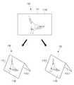
이 경우, 제어부(130)는 디스플레이부(110)가 벤딩되어 복수의 영역으로 분할되면, 객체에 대한 다시점 이미지 중 복수의 분할 영역의 배치 상태에 대응되는 이미지를 분할 영역에 디스플레이하도록 디스플레이부(110)를 제어할 수 있다. 이를 위해, 플렉서블 디스플레이 장치(100)는 객체에 대한 다시점 이미지를 저장하거나, 네트워크를 통해 외부 서버(미도시)로부터 제공받을 수 있다. 이 경우, 플렉서블 디스플레이 장치(100)는 네트워크 통신 가능한 통신부(미도시)를 더 포함할 수 있으며, 분할 영역의 배치 상태에 대응되는 이미지를 수신할 수 있다.In this case, when the
여기에서, 다시점 이미지란, 3차원 형상을 갖는 객체를 복수의 시점에서 촬영한 이미지로 보다 구체적인 설명을 위해 도 19 및 도 20을 참조하도록 한다.Here, the multi-view image refers to an image photographed from a plurality of viewpoints of an object having a three-dimensional shape, and for more detailed description, refer to FIGS. 19 and 20.
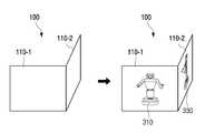
도 19 및 도 20은 본 발명의 일 실시 예에 따른 다시점 이미지를 설명하기 위한 도면들이다. 설명의 편의를 위해, 도 19 및 도 20에서 다시점 이미지는 3차원 형상을 갖는 사물을 복수의 시점에서 촬영한 이미지인 것으로 상정한다.19 and 20 are views for explaining a multi-view image according to an embodiment of the present invention. For convenience of explanation, it is assumed that the multi-view image in FIGS. 19 and 20 is an image photographed from a plurality of viewpoints of an object having a three-dimensional shape.
다시점 이미지는, 객체를 중심으로, 객체와 기설정된 거리만큼 이격된 지점을 반지름으로 하는 가상의 구면을 따라 객체를 촬영한 이미지들을 포함할 수 있다. 즉, 다시점 이미지는 가상의 구면을 따라 다양한 시점에서 객체를 촬영한 이미지들을 포함할 수 있다.The multi-view image may include images photographing an object along a virtual spherical surface having a radius of a point spaced apart from the object by a predetermined distance with the object as the center. That is, the multi-view image may include images photographing an object from various viewpoints along a virtual spherical surface.
예를 들어, 도 19와 같이, 다시점 이미지는 3차원 형상을 갖는 사물을 정면에서 촬영한 이미지(310)와 정면을 기준으로 우측 방향으로 일정한 각도만큼 벗어난 지점에서 객체를 순차적으로 촬영한 이미지들(320 내지 380)을 포함할 수 있다. 또한, 도 20과 같이, 다시점 이미지는 3차원 형상을 갖는 사물을 정면에서 촬영한 이미지(410)와 정면을 기준으로 상측 방향으로 일정한 각도만큼 벗어난 지점에서 객체를 순차적으로 촬영한 이미지들(420 내지 480)을 포함할 수 있다.For example, as shown in FIG. 19, a multi-view image is an
한편, 도 19 및 도 20에 도시된 이미지들은 다시점 이미지에 포함된 일 예일 뿐이다. 즉, 다시점 이미지는 가상의 구면을 따라 객체를 촬영한 이미지들이라는 점에서, 객체를 정면에서 대각선 방향으로 일정한 각도만큼 벗어난 지점에서 객체를 순차적으로 촬영한 이미지들 등을 포함할 수 있음은 물론이다.Meanwhile, the images shown in FIGS. 19 and 20 are only examples included in the multiview image. That is, in that multi-view images are images photographing an object along a virtual spherical surface, of course, it may include images sequentially photographing an object at a point deviating from the front by a certain angle in a diagonal direction. to be.
한편, 제어부(130)는 다시점 이미지 중 디스플레이부(110)의 벤딩 상태에 따라 대응되는 이미지를 각 분할 영역에 디스플레이할 수 있다. 보다 구체적인 설명을 위해 도 21 내지 도 25를 참조하도록 한다.Meanwhile, the
도 21 내지 도 25는 본 발명의 일 실시 예에 따라 분할 영역의 배치 상태에 따라 화면을 디스플레이하는 방법을 설명하기 위한 도면들이다.21 to 25 are diagrams for explaining a method of displaying a screen according to an arrangement state of a divided area according to an embodiment of the present invention.
제어부(130)는 감지부(120)의 감지 결과에 기초하여, 디스플레이부(110)의 벤딩에 의해 분할된 복수의 영역의 배치 상태를 판단한다.The
이를 위해, 감지부(120)는 가속도 센서(즉, 중력 센서, G 센서)를 구비할 수 있다. 여기에서, 가속도 센서는 디스플레이부(110)에 중력이 어느 방향으로 작용하는지를 감지하기 위한 센서이다. 이에 따라, 제어부(130)는 가속도 센서의 센싱 결과에 기초하여, 디스플레이부(110)의 자세 즉, 디스플레이부(110)의 배치 방향 및 기울어진 정도를 판단할 수 있다. 여기에서, 디스플레이부(110)의 배치 방향은 디스플레이부(110)가 가로 방향으로 배치되었는지 또는 세로 방향으로 배치되었는지를 포함할 수 있고, 디스플레이부(110)의 기울어진 정도는 가로 방향 또는 세로 방향으로 배치된 디스플레이부(110)가 중력 방향을 기준으로 기울어진 정도를 포함할 수 있다.To this end, the
그리고, 제어부(130)는 벤드 센서의 센싱 결과를 참조하여 디스플레이부(110)의 벤딩 각도 및 벤딩 방향을 판단하고, 판단된 결과들을 종합적으로 고려하여 복수의 분할 영역의 배치 상태를 판단할 수 있다.In addition, the
예를 들어, 디스플레이부(110)가 도 21과 같은 벤딩 상태를 갖는 경우, 제어부(130)는 제1 분할 영역(110-1)은 가로 방향으로 기울어짐 없이 배치되고, 제2 분할 영역(110-2)은 제1 분할 영역(110-1)을 기준으로 우측에서 Z- 방향으로 90°만큼 벤딩된 상태로 배치되는 것으로 판단할 수 있다. 다른 예로, 디스플레이부(110)가 도 22와 같은 벤딩 상태를 갖는 경우, 제어부(130)는 제1 분할 영역(110-1)은 세로 방향으로 기울어짐 없이 배치되고, 제2 분할 영역(110-2)은 제1 분할 영역(110-1)을 기준으로 상측에서 Z- 방향으로 90°만큼 벤딩된 상태로 배치되는 것으로 판단할 수 있다.For example, when the
한편, 제어부(130)는 복수의 분할 영역의 배치 상태에 따라, 각 분할 영역이 3차원 객체를 바라보는 시점을 판단한다. 구체적으로, 제어부(130)는 각 분할 영역의 중심을 통과하며, 각 분할 영역에 수직인 가상의 직선들이 서로 만나는 지점에 3차원 객체를 배치시켰을 때, 각 분할 영역이 3차원 객체를 바라보는 시점을 판단할 수 있다.Meanwhile, the
그리고, 제어부(130)는 다시점 이미지 중에서 각 분할 영역이 3차원 객체를 바라보는 시점에 대응되는 이미지를 검출하고, 검출된 이미지를 각 분할 영역에 디스플레이할 수 있다. 구체적으로, 제어부(130)는 다시점 이미지 중에서 각 분할 영역이 3차원 객체를 향하는 방향과 동일한 방향에서 3차원 객체를 촬영한 이미지를 검출하고, 검출된 각 이미지를 각 분할 영역에 디스플레이할 수 있다.In addition, the
예를 들어, 도 23과 같이, 제1 분할 영역(110-1)이 가로 방향으로 기울어짐 없이 배치되고, 제2 분할 영역(110-2)이 제1 분할 영역(110-1)을 기준으로 우측에서 Z- 방향으로 90°만큼 벤딩된 상태로 배치된 것으로 판단된 경우를 가정한다.For example, as shown in FIG. 23, the first divided area 110-1 is disposed without inclining in the horizontal direction, and the second divided area 110-2 is based on the first divided area 110-1. Assume that it is determined to be arranged in a state bent 90° from the right in the Z-direction.
이 경우, 제어부(130)는 제1 분할 영역(110-1)이 3차원 객체를 정면에서 바라보는 것으로 판단하고, 제2 분할 영역(110-2)이 정면을 기준으로 우측으로 90°만큼 벗어난 지점에서 3차원 객체를 바라보는 것으로 판단할 수 있다.In this case, the
이에 따라, 제어부(130)는 다시점 이미지 중에서 3차원 객체를 정면에서 촬영한 이미지를 제1 분할 영역(110-1)에 디스플레이하고, 3차원 객체를 정면을 기준으로 우측으로 90°만큼 벗어난 지점에서 촬영한 이미지를 제2 분할 영역(110-2)에 디스플레이할 수 있다. 예를 들어, 도 19와 같은 다시점 이미지의 경우, 도 23과 같이 제어부(130)는 이미지(310)를 제1 분할 영역(110-1)에 디스플레이하고 이미지(330)를 제2 분할 영역(110-2)에 디스플레이할 수 있다.Accordingly, the
한편, 제어부(130)는 디스플레이부(110)에 디스플레이되던 객체를 복수의 영역 중 하나에 디스플레이하고 객체에 대한 다시점 이미지 중 디스플레이부(100)의 벤딩 각도에 대응되는 이미지를 나머지 분할 영역에 디스플레이할 수 있다.Meanwhile, the
이를 위해, 제어부(130)는 디스플레이부(110)가 벤딩되기 전에, 디스플레이부(110)의 배치 상태를 판단하고, 다시점 이미지 중에서 판단된 배치 상태에 대응되는 이미지를 디스플레이부(110)에 디스플레이할 수 있다.To this end, the
구체적으로, 제어부(130)는 벤딩되기 전의 디스플레이부(110)가 3차원 객체를 바라보는 시점을 판단하고, 다시점 이미지 중에서 벤딩되기 전의 디스플레이부(110)가 3차원 객체를 바라보는 시점에서 촬영된 이미지를 검출하여 디스플레이할 수 있다.Specifically, the
예를 들어, 도 24와 같이 디스플레이부(110)가 가로 방향으로 기울어짐 없이 배치된 경우, 제어부(130)는 디스플레이부(110)가 3차원 객체를 정면에서 바라보는 방향으로 배치된 것으로 판단한다. 그리고, 제어부(130)는 도 19와 같은 다시점 이미지 중 이미지(310)를 디스플레이부(110)에 디스플레이할 수 있다.For example, as shown in FIG. 24, when the
이후, 디스플레이부(110)가 벤딩되면, 제어부(130)는 벤딩 각도 및 벤딩 방향을 고려하여 각 분할 영역의 배치 상태를 판단하고, 다시점 이미지 중에서 판단된 배치 상태에 대응되는 이미지를 각 분할 영역에 디스플레이할 수 있다.Thereafter, when the
이때, 제어부(130)는 디스플레이부(110)의 벤딩에 의해 형성된 복수의 분할 영역 중 적어도 하나가 디스플레이부(110)가 벤딩되기 이전의 배치 상태를 유지하는 경우, 이전의 배치 상태를 유지하는 분할 영역에는 벤딩되기 이전에 디스플레이부(110)에 디스플레이되던 이미지를 디스플레이할 수 있다. 그리고, 제어부(130)는 나머지 분할 영역에 대해서는, 다시점 이미지 중에서 해당 분할 영역의 벤딩 상태에 대응되는 이미지를 디스플레이할 수 있다.In this case, when at least one of the plurality of divided regions formed by bending of the
예를 들어, 도 24와 같이 디스플레이부(110)가 벤딩되어 제1 분할 영역(110-5)은 디스플레이부(110)가 벤딩되기 이전과 동일한 배치 상태를 갖고, 제2 분할 영역(110-6)은 제1 분할 영역(110-1)을 기준으로 좌측에서 Z- 방향으로 90°만큼 벤딩된 경우를 가정한다.For example, as shown in FIG. 24, the
이 경우, 제어부(130)는 벤딩되기 이전의 디스플레이부(110)와 동일한 배치 상태를 갖는 제1 분할 영역(110-5)에는 이미지(310)를 디스플레이할 수 있다. 그리고, 제어부(130)는 제2 분할 영역(110-6)은 정면을 기준으로 좌측으로 90°만큼 벗어난 3차원 객체를 바라본 방향으로 배치된 것으로 판단하여, 정면을 기준으로 좌측으로 90°만큼 벗어난 지점에서 3차원 객체를 촬영한 이미지를 제2 분할 영역(110-6)에 디스플레이할 수 있다. 예를 들어, 도 19와 같은 다시점 이미지의 경우, 도 24와 같이 제어부(130)는 이미지(370)를 제2 분할 영역(110-6)에 디스플레이할 수 있다.In this case, the
한편, 감지부(120)는 디스플레이부(110)에 대한 회전을 감지할 수 있다. 예를 들어, 감지부(120)는 지자기 센서 또는 자이로 센서를 통해 디스플레이부(110)의 회전 방향 및 회전 각도를 감지하고, 감지 결과를 제어부(130)로 전달할 수 있다.Meanwhile, the
제어부(130)는 디스플레이부(110)가 회전되어 복수의 분할 영역의 배치 상태가 변경되면, 복수의 분할 영역 각각에 디스플레이되던 이미지를 변경된 배치 상태에 대응되는 이미지로 대체하여 디스플레이할 수 있다. 구체적으로, 제어부(130)는 디스플레이부(110)의 회전 방향 및 회전 각도에 기초하여 복수의 분할 영역 각각의 배치 상태를 판단하고, 객체에 대한 다시점 이미지 중 판단된 배치 상태에 대응되는 이미지를 복수의 분할 영역 각각에 디스플레이할 수 있다.When the
예를 들어, 도 25와 같이, 제1 분할 영역(110-1)이 가로 방향으로 기울어짐 없이 배치되고 제2 분할 영역(110-2)이 제1 분할 영역(110-1)을 기준으로 우측에서 Z- 방향으로 90°만큼 벤딩된 상태로 배치된 경우, 제어부(130)는 도 19의 이미지(310) 및 이미지(330)를 제1 분할 영역(110-1) 및 제2 분할 영역(110-2)에 각각 디스플레이할 수 있다.For example, as shown in FIG. 25, the first divided area 110-1 is disposed without inclination in the horizontal direction, and the second divided area 110-2 is on the right side with respect to the first divided area 110-1. When arranged in a state that is bent by 90° in the Z-direction, the
이후, 디스플레이부(110)가 회전되면, 제어부(130)는 회전 방향 및 회전 각도에 기초하여 복수의 분할 영역 각각의 배치 상태를 다시 판단한다. 예를 들어, 도 24와 같이 제1 분할 영역(110-1) 및 제2 분할 영역(110-2)이 우측으로 45°만큼 회전되면, 제어부(130)는 각 분할 영역(110-1, 110-2)이 회전되기 이전의 배치 상태를 기준으로 우측으로 45°만큼 회전된 상태인 것으로 판단할 수 있다.Thereafter, when the
그리고, 제어부(130)는 회전에 의해 변경된 배치 상태를 갖는 각 분할 영역이 바라보는 시점을 판단하고, 다시점 이미지 중에서 각 분할 영역이 바라보는 시점에서 촬영한 이미지를 검출하여 각 분할 영역에 디스플레이할 수 있다. 이 경우, 제어부(130)는 각 분할 영역이 바라보던 시점을 디스플레이부(110)가 회전된 방향으로 회전된 각도만큼 이동시켜, 회전된 각 분할 영역이 바라보는 시점을 판단하고, 판단된 시점에서 촬영된 이미지를 검출하여 디스플레이할 수 있다.In addition, the
예를 들어, 도 24의 경우, 각 분할 영역이 우측으로 45°만큼 회전되었다는 점에서, 제어부(130)는 이미지(310) 및 이미지(330)를 촬영한 방향에서 각각 우측으로 45°만큼 벗어난 지점에서 3차원 객체를 촬영한 이미지를 검출하여 각 분할 영역(110-1, 110-2)에 디스플레이한다. 이에 따라, 제1 분할 영역(110-1)에는 정면을 기준으로 우측으로 45°만큼 벗어난 지점에서 3차원 사물을 촬영한 이미지(320)가 디스플레이되고, 제2 분할 영역(110-2)에는 우측 90°지점을 기준으로 우측으로 45°만큼 벗어난 지점 즉, 정면을 기준으로 우측으로 135°만큼 벗어난 지점에서 3차원 사물을 촬영한 이미지(340)가 디스플레이될 수 있다. 그리고, 도 24와 같이, 각 분할 영역(110-1, 110-2)이 우측으로 45°만큼 다시 회전되면, 제1 분할 영역(110-1)에는 우측 90°지점에서 3차원 사물을 촬영한 이미지(330)가 디스플레이되고, 제2 분할 영역(110-2)에는 후면에서 3차원 사물을 촬영한 이미지(350)가 디스플레이될 수 있다.For example, in the case of FIG. 24, in that each divided area is rotated by 45° to the right, the
한편, 상술한 실시 예에서는 디스플레이부(110)가 바깥쪽으로 벤딩된 경우(즉, Z- 방향으로 벤딩된 경우), 다시점 이미지 중 각 분할 영역이 바라보는 시점에서 촬영한 이미지가 디스플레이되는 것으로 설명하였으나 이는 일 예에 불과하다. 즉, 디스플레이부(110)가 안쪽으로 벤딩된 경우(즉, Z+ 방향으로 벤딩된 경우)에도 각 분할 영역의 배치 상태에 대응되는 화면이 디스플레이될 수 있다. 이 경우, 제어부(130)는 Z- 방향으로 벤딩되어 형성된 각 분할 영역에 디스플레이되는 이미지가 디스플레이부(110)가 Z+ 방향으로 벤딩된 경우에도 디스플레이할 수 있다.Meanwhile, in the above-described embodiment, when the
또한, 상술한 실시 예에서는 디스플레이부(110)가 1회 벤딩되는 경우, 각 분할 영역의 배치 형태에 따라 화면이 디스플레이되는 것을 설명하였으나 이는 일 예에 불과하다. 즉, 디스플레이부가 2회 벤딩되어 디스플레이부의 전체 영역이 3개의 분할 영역으로 구분되는 경우에도, 다시점 이미지 중에서 각 분할 영역의 배치 상태에 매칭되는 이미지가 각 분할 영역에 디스플레이될 수 있음은 물론이다.In addition, in the above-described embodiment, when the
또한, 상술한 실시 예외에도 플렉서블 디스플레이 장치(100)는 디스플레이부(110)의 벤딩에 따라 형성된 분할 영역의 배치 상태에 따라 다양한 화면을 디스플레이할 수 있다.In addition, even with the above-described exceptions, the
도 26 내지 도 28은 본 발명의 다른 실시 예에 따라 분할 영역의 배치 상태에 따라 화면을 디스플레이하는 방법을 설명하기 위한 도면들이다.26 to 28 are diagrams for explaining a method of displaying a screen according to an arrangement state of a divided area according to another embodiment of the present invention.
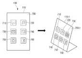
한편, 본 발명의 다른 실시 예에 따르면, 제어부(130)는 입체 UI를 구성하는 복수의 UI 면에서 분할 영역의 배치 상태에 대응되는 UI 면을 판단하고, 판단된 UI 면에 대한 그래픽 정보를 각 분할 영역에 디스플레이할 수 있다.Meanwhile, according to another embodiment of the present invention, the
여기에서, 입체 UI는 다면체 형상을 갖는 입체 UI로, 각 면에는 UI 화면이 표시될 수 있다. 예를 들어, 입체 UI는 도 26과 같이 입체 UI는 육면체로 구현되고, 각 UI 면에서는 UI 화면이 디스플레이될 수 있다. 여기에서, 도 26(a)는 입체 UI를 정면 상단에서 바라본 도면이고, 도 26(b)는 입체 UI를 후면 하단에서 바라본 도면이다.Here, the three-dimensional UI is a three-dimensional UI having a polyhedral shape, and a UI screen may be displayed on each side. For example, as for the three-dimensional UI, as shown in FIG. 26, the three-dimensional UI is implemented as a hexahedron, and a UI screen may be displayed on each UI surface. Here, FIG. 26(a) is a view of the three-dimensional UI as viewed from the top front, and FIG. 26(b) is a view of the three-dimensional UI as viewed from the bottom of the rear.
도 26(a) 및 도 26(b)에 도시된 바와 같이, 육면체 UI(400)의 각 UI 면은 다양한 UI 화면으로 구성될 수 있으며, 플렉서블 디스플레이 장치(100)는 각 UI 면에 디스플레이되는 그래픽 정보 즉, UI 화면에 대한 정보를 저장할 수 있다.26(a) and 26(b), each UI surface of the
예를 들어, 육면체 UI(400)는 플렉서블 디스플레이 장치(100)에 설치된 어플리케이션에 대한 아이콘들로 구성된 제1 UI 면(410), 동영상 어플리케이션에서 재생 가능한 동영상에 대한 썸네일 이미지들로 구성된 제2 UI 면(420), 각종 위젯으로 구성된 제3 UI 면(430), 카메라 어플리케이션에서 재생 가능한 이미지로 구성된 제4 UI 면(440), 캘린더 어플리케이션에서 실행되는 캘린더로 구성된 제5 UI 면(450), 음악 어플레케이션에서 실행 가능한 음악 파일에 대한 앨범 이미지로 구성된 제6 UI 면(460)을 포함할 수 있다.For example, the
다만, 도 26에 도시된 육면체 UI에서 각 UI 면을 구성하는 UI 화면을 일 예일 뿐, 다양하게 변경가능함은 물론이다.However, the UI screen constituting each UI surface in the hexahedral UI shown in FIG. 26 is merely an example, and of course, various changes are possible.
한편, 이러한 입체 UI는 플렉서블 디스플레이 장치(100)에 기저장되어 있을 수 있거나, 네트워크 통해 외부 서버(미도시)로부터 제공받을 수 있다. 이 경우, 플렉서블 디스플레이 장치(100)는 네트워크 통신 가능한 통신부(미도시)를 더 포함할 수 있으며, 분할 영역의 배치 상태에 대응되는 각 UI면에 대한 그래픽 정보(즉, UI 화면에 대한 정보)를 수신할 수 있다.Meanwhile, the three-dimensional UI may be previously stored in the
제어부(130)는 감지부(120)의 감지 결과에 기초하여, 복수의 분할 영역의 배치 상태를 판단한다. 이를 위해, 감지부(120)는 가속도 센서를 구비하여 디스플레이부(110)의 자세를 감지하고, 벤드 센서를 구비하여 디스플레이부(110)의 벤딩 각도 및 벤딩 방향을 감지할 수 있다. 한편, 제어부(130)는 이러한 감지부(120)의 센싱 결과를 종합적으로 고려하여 복수의 분할 영역의 배치 상태를 판단할 수 있다.The
먼저, 제어부(130)는 가속도 센서의 센싱값에 기초하여 디스플레이부(110)의 자세를 판단할 수 있다. 구체적으로, 제어부(130)는 디스플레이부(110)가 기울어짐에 따라 가속도 센서에서 출력되는 센싱값을 이용하여, 디스플레이부(110)의 배치 방향(즉, 가로 방향 또는 세로 방향) 및 중력 방향에 대해 기울어진 정도를 판단할 수 있다.First, the
그리고, 제어부(130)는 각 분할 영역의 배치 상태에 따라, 입체 UI을 구성하는 복수의 UI 화면 중에서 적어도 2개의 UI 화면을 각 분할 영역에 디스플레이할 수 있다. 예를 들어, 제어부(130)는 각 분할 영역의 배치 상태에 따라, 육면체 UI에서 각 분할 영역에 매칭되는 UI 면을 판단하고, 판단된 UI 면을 구성하는 UI 화면을 각 분할 영역에 디스플레이할 수 있다.In addition, the
예를 들어, 도 27과 같이, 제2 분할 영역(110-2)은 가로 방향으로 기울어짐 없이 배치된 상태이고, 제1 분할 영역(110-1)은 제2 분할 영역(110-2)의 좌측에서 Z+ 방향으로 90°만큼 벤딩된 상태인 경우, 제어부(130)는 제1 분할 영역(110-1)은 육면체의 좌측면(즉, 도 26의 제6 UI 면(460))에 매칭되고, 제2 분할 영역(110-2)은 정면을 기준으로 육면체의 뒷면(즉, 도 26의 제4 UI 면(440))에 매칭되는 것으로 판단할 수 있다. 이에 따라, 제어부(130)는 음악 어플레케이션에서 실행 가능한 음악 파일에 대한 앨범 이미지로 구성된 UI 화면(460)을 제1 분할 영역(110-1)에 디스플레이하고, 카메라 어플리케이션에서 재생 가능한 이미지로 구성된 UI 화면(440)을 제2 분할 영역(110-2)에 디스플레이할 수 있다.For example, as shown in FIG. 27, the second divided area 110-2 is disposed without inclination in the horizontal direction, and the first divided area 110-1 is a second divided area 110-2. In the case of being bent by 90° from the left to the Z+ direction, the
한편, 제어부(130)는 UI 화면이 디스플레이된 상태에서 디스플레이부(110)가 회전되면, 회전된 각 분할 영역의 배치 상태에 따라 UI 면 중에서 회전된 분할 영역에 대응되는 UI 면을 판단하고, 판단된 UI 면에 대응되는 그래픽 정보를 각 분할 영역에 디스플레이할 수 있다. 이를 위해, 감지부(120)는 지자기 센서 또는 자이로 센서를 통해 디스플레이부(110)의 회전 방향 및 회전 각도를 감지하고, 감지 결과를 제어부(130)로 전달할 수 있다.On the other hand, when the
구체적으로, 제어부(130)는 디스플레이부(110)가 회전되면 회전된 각 분할 영역의 배치 상태를 다시 판단하고, 입체 UI에서 각 분할 영역의 배치 상태에 대응되는 UI 면을 검출할 수 있다. 즉, 제어부(130)는 회전된 각 분할 영역의 배치 상태에 매칭되는 UI 면을 검출할 수 있다.Specifically, when the
예를 들어, 도 27에 도시된 각 분할 영역(110-1, 110-2)이 90°만큼 회전되어 도 28과 같이 세워진 경우를 가정한다. 이 경우, 제어부(130)는 제1 분할 영역(110-1)은 세로 방향으로 지면에 평행하도록 기울어진 상태이고, 제2 분할 영역(110-2)은 제1 분할 영역(110-1)의 상측에서 Z+ 방향으로 90°만큼 벤딩된 상태인 것으로 판단할 수 있다.For example, it is assumed that the divided regions 110-1 and 110-2 shown in FIG. 27 are rotated by 90° and erected as shown in FIG. 28. In this case, the
이에 따라, 제어부(130)는 회전된 제1 분할 영역(110-1)은 육면체의 밑면(즉, 도 26의 제5 UI 면(450))에 매칭되고, 제2 분할 영역(110-2)은 육면체의 뒷면(즉, 도 26의 제5 UI 면(440))에 매칭되는 것으로 판단할 수 있다. 그리고, 제어부(130)는 음악 어플레케이션에서 실행 가능한 음악 파일에 대한 앨범 이미지로 구성된 UI 화면(460)을 제1 분할 영역(110-1)에 디스플레이하고, 어플리케이션에서 실행되는 캘린더로 구성된 UI 화면(450)을 제2 분할 영역(110-2)에 디스플레이할 수 있다.Accordingly, the
이 경우, 제어부(130)는 가속도 센서에 의해 판단된 디스플레이부(110)의 자세에 기초하여, 디스플레이되는 UI 화면의 표시 방향을 회전할 수 있다. 즉, 제어부(130)는 디스플레이부(110)가 가로 방향으로 배치된 경우 UI 화면을 가로 방향으로 디스플레이하고, 디스플레이부(110)가 세로 방향으로 배치된 경우 UI 화면을 세로 방향으로 회전시켜 디스플레이할 수 있다.In this case, the
한편, 상술한 실시 예에서는 디스플레이부(110)가 안쪽으로 벤딩된 경우(즉, Z+ 방향으로 벤딩된 경우), 각 분할 영역에 매칭되는 UI 화면이 디스플레이되는 것으로 설명하였으나 이는 일 예에 불과하다. 즉, 디스플레이부(110)가 바깥쪽으로 벤딩된 경우(즉, Z- 방향으로 벤딩된 경우)에도 각 분할 영역의 배치 상태에 대응되는 UI 화면이 디스플레이될 수 있다. 이 경우, 제어부(130)는 Z+ 방향으로 벤딩되어 형성된 각 분할 영역에 디스플레이되는 이미지가 디스플레이부(110)가 Z- 방향으로 벤딩된 경우에도 디스플레이할 수 있다.Meanwhile, in the above-described embodiment, it has been described that when the
도 29는 본 발명의 다른 실시 예에서 분할 영역의 배치 상태에 따라 화면을 디스플레이하는 방법을 설명하기 위한 도면이다. 특히, 도 29는 게임 화면이 복수의 분할 영역에 디스플레이되는 방법을 설명하기 위한 도면이다.29 is a diagram for explaining a method of displaying a screen according to an arrangement state of a divided area according to another embodiment of the present invention. In particular, FIG. 29 is a diagram illustrating a method of displaying a game screen in a plurality of divided areas.
예를 들어, 도 29(a)와 같이 레이싱 게임이 실행되어 자동차에서 정면을 바라보는 게임 실행 화면이 디스플레이부(110)에 디스플레이된 경우를 가정한다. 이후, 디스플레이부(110)가 2회 벤딩되면 도 29(b)와 같이 디스플레이부(110)가 복수의 분할 영역으로 구분될 수 있다. 즉, 디스플레이부(110)는 가로 방향으로 기울어짐이 없는 상태로 배치된 제1 분할 영역(110-1), 제1 분할 영역(110-1)을 기준으로 좌측에서 Z+ 방향으로 벤딩되어 형성된 제2 분할 영역(110-2), 제1 분할 영역(110-1)을 기준으로 우측에서 Z+ 방향으로 벤딩되어 형성된 제3 분할 영역(110-3)으로 구분될 수 있다.For example, it is assumed that a racing game is executed as shown in FIG. 29(a) and the game execution screen facing the front from the car is displayed on the
이 경우, 3차원 공간상의 한 지점(500)을 기준으로 제1 분할 영역(110-1)은 정면에 위치하며 제2 분할 영역(110-2)은 좌측에 위치하며, 제3 분할 영역(110-3)은 우측에 위치하게 된다. 이에 따라, 제1 분할 영역(110-1)에는 정면을 바라본 게임 실행 화면이 디스플레이되고, 제2 분할 영역(110-2)에는 좌측을 바라본 게임 실행 화면이 디스플레이되고, 제3 분할 영역(110-3)에는 우측을 바라보는 게임 실행 화면이 디스플레이될 수 있다.In this case, based on a
한편, 제어부(130)는 디스플레이부(110)가 벤딩되면 벤딩된 상태를 유지하도록 제어할 수 있다. 이를 위해, 플렉서블 디스플레이 장치(100)는 복수 개의 폴리머 필름을 포함할 수 있으며, 제어부(130)는 폴리머 필름에 전압을 인가하여 디스플레이부(110)가 벤딩된 상태를 유지하도록 제어할 수 있다.Meanwhile, when the
도 30은 본 발명의 일 실시 예에서 플렉서블 디스플레이 장치가 벤딩 상태를 유지하는 방법을 설명하기 위한 도면이다.FIG. 30 is a diagram for describing a method of maintaining a bending state of a flexible display device according to an embodiment of the present invention.
상술한 바와 같이, 플렉서블 디스플레이 장치(100)는 디스플레이부(110)의 일면 또는 양면에 장착된 복수 개의 폴리머 필름을 포함할 수 있다.As described above, the
폴리머 필름은 실리콘 또는 우레탄 계열의 유전 탄성체(dielectric elastomer)로서, 일측과 타측 각각에 전극이 도포되고 각 전극에 인가되는 전압의 전위차에 따라 형상이 변형된다.The polymer film is a silicone or urethane-based dielectric elastomer, and an electrode is applied to each of one side and the other side, and its shape is deformed according to the potential difference of the voltage applied to each electrode.
예를 들어, 도 30(a)와 같이 폴리머 필름(121)에 일정한 크기의 전압이 인가되면, 폴리머 필름(121)의 위쪽 부분은 수축되고 아래쪽 부분은 신장될 수 있다. 따라서, 제어부(130)는 폴리머 필름(121)에 전압을 인가하여 폴리머 필름(121)의 형상을 변형시켜, 디스플레이부(110)가 벤딩된 상태를 유지하도록 제어할 수 있다.For example, when a voltage of a certain size is applied to the
한편, 플렉서블 디스플레이 장치(100)는 디스플레이부(110)를 일정한 상태로 벤딩시키기 위해 디스플레이부(110)에 배치된 폴리머 필름 중 어떠한 폴리머 필름에 전압을 인가하여야 하는지, 얼마만큼의 전압을 폴리머 필름에 인가하여야 하는지, 어떠한 순서로 폴리머 필름에 전압을 인가하야야 하는지 등에 대한 정보(이하, 제어 정보)를 기저장하고 있을 수 있다. 이에 따라, 제어부(130)는 기저장된 제어 정보를 이용하여, 디스플레이부(110)의 벤딩 상태를 유지시키도록 폴리머 필름에 전압을 인가할 수 있다.Meanwhile, in order to bend the
구체적으로, 제어부(130)는 디스플레이부(110)가 벤딩되면 감지부(120)의 센싱 결과에 기초하여 벤딩 영역의 위치, 벤딩 각도 및 벤딩 방향 등의 벤딩 상태를 판단한다. 그리고, 제어부(130)는 기저장된 제어 정보를 이용하여, 디스플레이부(110)가 벤딩 상태를 유지하기 위해 전압이 인가되어야 하는 폴리머 필름의 위치, 인가되는 전압의 크기, 전압 인가 순서 등을 판단하고, 그에 따라 폴리머 필름에 전압을 인가하여 디스플레이부(110)가 벤딩된 상태를 유지하도록 제어할 수 있다.Specifically, when the
예를 들어, 도 30(b)와 같이, 디스플에이부(110)의 좌측이 Z+ 방향으로 45°만큼 벤딩된 경우를 가정한다. 이 경우, 제어부(130)는 벤딩 영역에 위치한 폴리머 필름(121-1 내지 121-5)에 일정한 크기의 전압을 인가하여 디스플레이부(110)가 좌측이 Z+ 방향으로 45°만큼 벤딩된 상태를 유지하도록 제어할 수 있다.For example, as shown in FIG. 30(b), it is assumed that the left side of the
한편, 상술한 실시 예에서는 폴리머 필름이 5개로 구현되는 것으로 도시하였으나 이는 설명의 편의를 위한 일 예일 뿐이고, 폴리머 필름의 개수 및 크기 등은 디스플레이부(110)의 크기에 따라 변경될 수 있다.Meanwhile, in the above-described embodiment, it is shown that five polymer films are implemented, but this is only an example for convenience of description, and the number and size of polymer films may be changed according to the size of the
또한, 상술한 실시 예에서는 디스플레이부(110)가 벤딩된 상태를 유지시키기 위해 플렉서블 디스플레이 장치(100)가 폴리머 필름을 포함하는 것으로 설명하였으나, 이는 일 예일 뿐이다. 이 밖에도, 플렉서블 디스플레이 장치(100)는 줄(string), 압전 소자(piezoelectric element)(가령, 바이모프 압전소자(series bimorph piezoelectric element, parallel bimorph piezoelectric element)), EAP(electro active polymer), EMP(electro mechnical polymer) 등을 포함하여, 디스플레이부(110)의 벤딩 상태를 유지시킬 수 있다.In addition, in the above-described embodiment, it has been described that the
예를 들어, 플렉서블 디스플레이 장치(100)가 줄을 포함하는 경우, 제어부(130)는 줄의 인장력을 변화시켜 디스플레이부(110)의 벤딩 상태를 유지시킬 수 있다. 즉, 디스플레이부(110)의 형상이 변형된 경우, 디스플레이부(110)는 자체 탄성에 의해 플랫한 상태로 돌아가려는 역방향의 힘을 받는다. 이 경우, 제어부(130)는 역방향 힘에 대응하는 만큼의 물리적인 힘을 줄에 제공하여 디스플레이부(110)가 벤딩된 상태를 유지하도록 제어할 수 있다.For example, when the
또한, 플렉서블 디스플레이 장치(100)는 형상기억합금(shape memory alloy)(미도시)을 구비할 수도 있다. 구체적으로, 형상기억합금(미도시)은 전이온도(轉移溫度) 온도 이하에서 변형하여도, 전이온도 이상이 되면 변형 이전의 모양으로 되돌아가는 성질을 가진 합금을 말한다. 여기에서, 전이온도는 물질의 상태가 전이할 때 그 물질 고유의 일정한 온도를 의미한다.In addition, the
구체적으로, 형상기억합금(미도시)은 전기적 신호가 제공되면 금속 내부 저항에 의해 열을 발생시킴으로써 그 모양을 변형시킨다. 즉, 형상기억합금(미도시)은 구부러진 형상을 기억하도록 제작되어, 보통 상태에서는 플랫한 상태를 유지하고 있다가 전기적 신호가 제공되면 내부 저항에 의해 열을 발생시킴으로써 내부 온도가 전이온도에 도달하는 경우 본래의 구부러진 형상으로 변형될 수 있다. 이와 같은, 형상기억합금은 니켈-티타늄 합금, 구리-아연-알루미늄 합금 등으로 구현될 수 있다.Specifically, the shape memory alloy (not shown) deforms its shape by generating heat by internal metal resistance when an electrical signal is provided. That is, the shape memory alloy (not shown) is manufactured to memorize the bent shape, and maintains a flat state in a normal state, and generates heat by internal resistance when an electrical signal is provided, so that the internal temperature reaches the transition temperature. If the case can be transformed into the original bent shape. Such a shape memory alloy may be implemented as a nickel-titanium alloy, a copper-zinc-aluminum alloy, or the like.
한편, 제어부(130)는 형상기억합금(미도시)에 선택적으로 전기적 신호를 제공할 수 있다. 구체적으로, 제어부(130)는 벤딩된 디스플레이부(110)의 벤딩 각도에 대응되는 전기적 신호를 형상기억합금(미도시)에 제공할 수 있다. 이를 위해, 형상기억합금(미도시)은 서로 다른 각도만큼 구부러진 형상을 기억하는 복수의 형상기억합금으로 구현될 수 있다. 즉, 제어부(미도시)는 복수의 형상기억합금 중에서 디스플레이부(110)가 벤딩된 각도만큼 구부러진 형상을 기억하는 형상기억합금에 전기적 신호를 제공하여, 디스플레이부(110)가 벤딩 각도별로 벤딩된 상태를 유지하도록 제어할 수 있다.Meanwhile, the
한편, 상술한 실시 예들에서, 제어부(130)는 벤딩 상태를 유지하기 위한 별도의 사용자 명령이 입력되거나 또는, 기설정된 시간 이상 일정한 각도로 벤딩 사태가 유지되면 디스플레이부(110)가 벤딩된 상태를 유지하도록 제어할 수 있다.Meanwhile, in the above-described embodiments, when a separate user command for maintaining the bending state is input, or when the bending situation is maintained at a predetermined angle for a predetermined time or longer, the
한편, 제어부(130)는 벤딩에 의해 디스플레이부(110)의 전체 영역이 복수의 분할 영역으로 구분된 경우, 디스플레이부(110)의 배치 상태에 따라 복수의 분할 영역을 선택적으로 활성화시키고 활성화된 분할 영역에 화면을 디스플레이할 수 있다.Meanwhile, when the entire area of the
구체적으로, 제어부(130)는 복수의 분할 영역 중 하나가 지지면에 접하도록 디스플레이부(110)가 배치되면, 지지면에 접하는 분할 영역을 비활성화시키고 나머지 분할 영역을 활성화시킬 수 있다. 또한, 제어부(130)는 복수의 분할 영역 전체가 지지면에 접하지 않도록 디스플레이부(110)가 배치되면, 복수의 분할 영역 전체를 활성화시킬 수 있다.Specifically, when the
이를 위해, 제어부(130)는 디스플레이부(110)가 벤딩되면, 디스플레이부(110)가 벤딩 라인을 기준으로 상하측, 좌우측 또는 대각선 방향으로 분할되어 복수의 분할 영역을 형성하는 것으로 판단한다.To this end, when the
그리고, 제어부(130)는 각 분할 영역이 지지면에 접하는지 여부에 기초하여 디스플레이부(110)의 배치 상태를 판단하고, 디스플레이부(110)의 배치 상태에 따라 분할 영역을 활성화 또는 비활성화시킬 수 있다. 여기에서, 지지면은, 테이블, 바닥, 사용자의 신체 일부(가령, 손바닥) 등을 포함할 수 있다. 이를 위해, 감지부(120)는 디스플레이부(110)의 상하좌우측 가장자리 영역 각각에 배치된 근접센서 및 가속도 센서를 포함할 수 있으며, 보다 구체적인 설명을 위해 도 31을 참조한다.Further, the
도 31은 본 발명의 일 실시 예에 따라 플렉서블 디스플레이 장치가 지지면에 디스플레이부가 접하도록 배치되었는지 여부를 판단하는 방법을 설명하기 위한 도면이다.31 is a diagram for describing a method of determining whether a flexible display device is disposed so as to contact a display unit on a support surface according to an embodiment of the present invention.
제어부(130)는 디스플레이부(110)가 벤딩되면 각 분할 영역에 배치된 가속도 센서 및 근접 센서의 센싱값에 기초하여, 분할 영역이 지지면에 접하였는지 여부를 판단할 수 있다.When the
구체적으로, 제어부(130)는 분할 영역이 지지면에 근접하거나 접촉되어 있고 분할 영역의 디스플레이 표면이 지지면(즉, 중력 방향)을 향하도록 벤딩된 경우, 해당 분할 영역이 지지면에 접하고 있는 것으로 판단할 수 있다. 이 경우, 제어부(130)는 지지면에 접하고 있는 분할 영역을 비활성화시키고, 지지면에 접하고 있지 않은 분할 영역을 활성화시켜 활성화된 분할 영역에 화면을 디스플레이할 수 있다.Specifically, when the divided area is in close contact with or in contact with the support surface and the display surface of the divided area is bent toward the support surface (ie, the direction of gravity), the corresponding divided area is in contact with the support surface. I can judge. In this case, the
한편, 제어부(130)는 디스플레이부(110)가 벤딩되어 복수의 분할 영역이 형성되었으나 지지면에 접하는 분할 영역이 존재하지 않는 것으로 판단되면, 모든 분할 영역을 활성화시켜 각 분할 영역에 화면을 디스플레이할 수 있다.On the other hand, if the
예를 들어, 도 31(a)에 도시된 바와 같이, 디스플레이부(110)가 벤딩에 의해 제1 분할 영역(110-1)과 제2 분할 영역(110-2)으로 구분되는 경우를 가정한다. 이 경우, 제2 분할 영역(110-2)은 테이블 표면(600)과 접하도록 놓여져 테이블 표면(600)과 근접하거나 접촉되어 있으며, 제2 분할 영역(110-2)의 디스플레이 표면은 지지면 방향으로 벤딩되어 있다. 이와 같은 경우, 제어부(130)는 제2 분할 영역(110-2)이 지지면에 접하는 것으로 디스플레이부(110)의 벤딩 상태를 판단하고, 제1 분할 영역(110-1)을 활성화시키고 제2 분할 영역(110-2)을 비활성화시킬 수 있다.For example, as shown in FIG. 31(a), it is assumed that the
한편, 도 31(b)에 도시된 바와 같이, 디스플레이부(110)가 벤딩에 의해 제1 분할 영역(110-3)과 제2 분할 영역(110-4)으로 구분된 경우를 가정한다. 이 경우에는, 제1 및 제2 분할 영역(110-3, 110-4) 모두 테이블 표면(600)에 접하지 않으며 지지면 방향으로 벤딩된 것도 아니라는 점에서, 제어부(130)는 지지면에 접하는 분할 영역이 존재하지 않는 것으로 판단하고, 제1 및 제2 분할 영역(110-3, 110-4) 모두를 활성화시킬 수 있다.Meanwhile, as shown in FIG. 31B, it is assumed that the
한편, 도 31(a) 및 도 31(b)에서, 디스플레이부(110)가 벤딩된 상태로 테이블 표면 상에 놓여지는 것으로 도시하였다. 이를 위해, 제어부(130)는 디스플레이부(110)가 벤딩된 상태를 계속 유지하도록 제어할 수 있다. 이에 대해서는, 도 30과 함께 설명한바 있다는 점에서 구체적인 중복설명은 생략하도록 한다Meanwhile, in FIGS. 31(a) and 31(b), it is shown that the
또한, 상술한 예에서는, 디스플레이부(110)의 배치 상태를 판단하기 위해 디스플레이부(110)의 상하좌우측 각각에 근접 센서 및 가속도 센서가 배치되는 것으로 설명하였으나, 이는 일 예에 불과하다.In addition, in the above-described example, it has been described that the proximity sensor and the acceleration sensor are disposed on each of the upper, lower, left, and right sides of the
즉, 근접센서 대신 압력 센서 등이 구비되어 지지면에 접촉시 가해지는 압력에 기초하여 지지면과의 접촉 여부를 판단할 수 있음은 물론이다. 또한, 사용자의 신체 일부에 접촉하는 경우, 터치 센서 등을 통해 사용자의 신체 일부와의 접촉 여부를 판단할 수도 있다.That is, a pressure sensor or the like is provided instead of the proximity sensor, and it is of course possible to determine whether or not to contact the support surface based on the pressure applied when contacting the support surface. In addition, when contacting a part of the user's body, it may be determined whether or not the user's body part is contacted through a touch sensor.
또한, 수광 센서를 이용하여 분할 영역이 지지면과 접하였는지 여부를 판단할 수도 있다. 즉, 지지면에 접하게 되는 분할 영역은 지지면에 의해 가려지게 되어 빛이 입사되지 않는다. 따라서, 디스플레이부(110)가 벤딩이 이루어져 복수의 분할 영역으로 구분된 후, 복수의 분할 영역 중에서 빛이 입사되지 않는 분할 영역이 존재하는 경우, 해당 분할 영역이 지지면과 접하는 것으로 판단할 수 있다.In addition, it may be determined whether or not the divided region is in contact with the support surface using a light receiving sensor. That is, the divided area that comes into contact with the support surface is covered by the support surface, so that no light is incident. Accordingly, after the
뿐만 아니라, 카메라를 이용하여 분할 영역이 지지면과 접하였는지 여부를 판단할 수도 있다. 즉, 지지면에 접하게 되는 분할 영역은 지지면에 의해 가려지게 되므로, 해당 분할 영역에 배치된 카메라로 촬상하게 되면 블랙 이미지가 촬상된다. 따라서, 복수의 분할 영역 중에서 블랙 이미지를 촬상한 분할 영역을 지지면과 접하는 것으로 판단할 수 있다.In addition, it is also possible to determine whether the divided area is in contact with the support surface using a camera. That is, since the divided area that comes into contact with the support surface is covered by the support surface, a black image is captured when an image is taken with a camera disposed on the divided area. Accordingly, it may be determined that the divided area in which the black image is captured among the plurality of divided areas is in contact with the support surface.
또한, 가속도 센서는 디스플레이부(110)의 좌측 또는 우측 가장자리 영역에 하나만 구비되고, 디스플레이부(110)의 상측 또는 하측 가장자리 영역에 하나만 구비될 수도 있다. 이 경우, 제어부(130)는 가속도 센서의 센싱값에 기초하여, 가속도 센서가 배치된 분할 영역이 향하는 방향을 판단하고, 판단된 분할 영역의 방향과 디스플레이부(110)의 벤딩 각도를 이용하여 나머지 분할 영역이 향하는 방향을 판단할 수 있다.Also, only one acceleration sensor may be provided in the left or right edge region of the
예를 들어, 도 31(a)에서 제1 분할 영역(110-1)에 가속도 센서가 구비되고, 제2 분할 영역(110-2)에는 가속도 센서가 구비되지 않은 경우를 가정한다. 이 경우, 제어부(130)는 가속도 센서의 센싱값에 기초하여 제1 분할 영역(110-1)과 중력 방향이 이루는 각도를 판단한다. 그리고, 제어부(130)는 판단된 제1 분할 영역(110-1)의 각도와 디스플레이부(110)의 벤딩 각도(즉, 제1 분할 영역(110-1)과 제2 분할 영역(110-2)이 이루는 각도)에 기초하여, 제2 분할 영역(110-2)이 중력 방향과 이루는 각도를 산출할 수 있다. 이에 따라, 제어부(130)는 가속도 센서가 구비되지 않은 분할 영역이 지지면 방향을 향하는지를 여부를 판단할 수 있게 된다.For example, in FIG. 31A, it is assumed that an acceleration sensor is provided in the first divided area 110-1 and no acceleration sensor is provided in the second divided area 110-2. In this case, the
한편, 상술한 실시 예에서는 디스플레이부(110)가 가로 방향으로 1회 벤딩되는 경우를 설명하였으나 이는 일 예일 뿐이다. 즉, 제어부(130)는 디스플레이부(110)가 가로 방향으로 2회 이상 벤딩되는 경우, 세로 방향으로 적어도 1회 이상 벤딩되는 경우, 가로 및 세로 방향으로 벤딩되는 경우에도 동일한 방법을 통해 디스플레이부(110)의 배치 상태를 판단하고, 판단 결과에 따라 분할 영역을 선택적으로 활성화시킬 수 있음은 물론이다.Meanwhile, in the above-described embodiment, a case where the
한편, 제어부(130)는 디스플레이부(110)의 배치 상태에 따라 분할 영역을 선택적으로 활성화시키고, 활성화된 분할 영역에 화면을 디스플레이할 수 있다. 여기에서, 화면은 이미지, 동영상, 음악, 텍스트 등과 같은 컨텐츠의 재생화면, 각종 웹 페이지 화면, UI 화면 등을 포함할 수 있다.Meanwhile, the
이 경우, 제어부(130)는 디스플레이부(110)의 전체 영역에 분포하는 디스플레이 소자 중에서 비활성된 분할 영역에 해당하는 디스플레이 소자를 턴오프 시킬 수 있다. 이는, 비활성화된 분할 영역은 디스플레이부(110)의 전체 영역 중 지지면에 접하는 영역으로 사용자에게 노출되지 않는다는 점에서, 제어부(130)는 불필요한 전력 소모를 방지하기 위해 비활성화된 분할 영역에 분포된 디스플레이 소자를 턴오프 시킬 수 있다.In this case, the
예를 들어, 디스플레이 패널(113)이 유기발광다이오드로 구현된 경우를 가정한다. 유기발광다이오드의 경우 각 픽셀별로 발광 소자가 배치되어 각 픽셀 단위로 온/오프되기 때문에, 제어부(130)는 비활성화된 분할 영역에 배치된 유기발광다이오드에 전원 공급을 차단하여 유기발광다이오드를 턴오프시킬 수 있다. 다른 예로, 디스플레이 패널(113)이 LCD로 구현되는 경우 별도의 백라이트를 구비하여야 한다. 이 경우, 제어부(130)는 비활성화된 분할 영역에 배치된 백라이트에 공급되는 전원을 차단시킬 수 있다. 이를 위해, 백라이트는 그리드 방식 등과 같이 영역별로 LCD에 백라이트를 제공하는 형태로 구현될 수 있다.For example, it is assumed that the
다른 한편, 제어부(130)는 비활성된 분할 영역에 블랙 영상(black image)을 디스플레이하거나, 아무런 영상을 디스플레이하지 않도록 제어할 수도 있다. 예를 들어, 유기발광다이오드와 같이 블랙 영상을 디스플레이하여 전력 소모를 줄일 수 있는 경우에는, 제어부(130)는 비활성된 분할 영역에 배치된 유기발광다이오드에 블랙 영상을 디스플레이할 수 있다.On the other hand, the
또한, 제어부(130)는 활성화된 분할 영역에 화면을 디스플레이할 수 있으며, 보다 구체적인 설명을 위해 도 32 내지 도 37을 참조하도록 한다.In addition, the
도 32 내지 도 37은 본 발명의 일 실시 예에 따라 플렉서블 디스플레이 장치가 분할 영역에 화면을 디스플레이하는 방법을 설명하기 위한 도면들이다. 도 32 내지 도 37에서는 디스플레이부(110)가 일정한 벤딩 각도를 유지하며, 지지면에 놓여진 경우를 도시하였다.32 to 37 are diagrams for explaining a method of displaying a screen in a divided area by a flexible display device according to an embodiment of the present invention. 32 to 37 illustrate a case where the
먼저, 제어부(130)는 활성화된 분할 영역의 크기에 맞도록 화면의 레이아웃을 변경할 수 있다. 구체적으로, 제어부(130)는 플랫한 상태에서 디스플레이부(110)에 디스플레이된 화면에 포함된 객체의 크기, 배열 위치 중 적어도 하나를 변경하여, 분할 영역에 화면을 디스플레이할 수 있다. 여기에서, 객체는 아이콘, 위젯, 이미지 등을 포함할 수 있다.First, the
예를 들어, 도 32와 같이, 플렉서블 디스플레이 장치(100)에 설치된 어플리케이션에 대한 아이콘(710 내지 760)을 포함하는 홈 화면(700)이 디스플레이부(110)이 디스플레이된 경우를 가정한다. 이후, 디스플레이부(110)가 벤딩에 의해 제1 분할 영역(110-1)과 제2 분할 영역(110-2)으로 구분되고 제2 분할 영역(110-2)이 지지면에 접하게 되면, 제어부(130)는 아이콘(710 내지 760)의 배치 위치가 변경된 홈 화면(700-1)을 제1 분할 영역(110-1)에 디스플레이할 수 있다.For example, as shown in FIG. 32, it is assumed that the
한편, 제어부(130)는 구동 중인 어플리케이션에 따라 화면의 레이아웃을 서로 다르게 변경할 수 있다. 즉, 도 33에 도시된 바와 같이, 캘린더 어플리케이션 구동에 따라 일일 캘린더(810)가 디스플레이부(110)에 디스플레이된 후, 디스플레이부(110)가 벤딩되고 제2 분할 영역(110-2)이 지지면에 접하게 되는 경우를 가정한다. 이 경우, 제어부(130)는 화면의 레이아웃이 변경되어 월별 캘린더(820)를 제1 분할 영역(110-1)에 디스플레이할 수 있다.Meanwhile, the
또한, 제어부(130)는 활성화된 분할 영역의 크기에 맞도록 화면의 크기를 변경할 수 있다. 구체적으로, 제어부(130)는 플랫한 상태에서 디스플레이부(110)에 디스플레이된 화면의 크기를 활성화된 분할 영역의 크기에 맞도록 스케일링하여, 분할 영역에 화면을 디스플레이할 수 있다.Also, the
예를 들어, 도 34와 같이, 이미지(910)가 디스플레이부(110)에 디스플레이된 경우를 가정한다. 이후, 디스플레이부(110)가 벤딩에 의해 제1 분할 영역(110-1)과 제2 분할 영역(110-2)으로 구분되고 제2 분할 영역(110-2)이 지지면에 접하게 되면, 제어부(130)는 디스플레이되던 이미지(910)의 크기를 축소하여 제1 분할 영역(110-1)에 디스플레이할 수 있다.For example, as shown in FIG. 34, it is assumed that the
한편, 상술한 실시 예에서는, 활성화된 분할 영역의 크기에 맞도록 화면의 사이즈가 변경되는 것으로 설명하였으나 이는 일 예에 불과하다. 즉, 제어부(130)는 화면을 기설정된 비율을 갖도록 활성화된 분할 영역에 디스플레이할 수도 있다.Meanwhile, in the above-described embodiment, it has been described that the size of the screen is changed to fit the size of the active divided area, but this is only an example. That is, the
예를 들어, 제어부(130)는 활성화된 분할 영역의 크기(가령, 해상도)가 1920*1200인 경우를 가정한다. 이때, 제어부(130)가 4:3 비율의 화면을 활성화된 분할 영역에 디스플레이하고자 하는 경우, 활성화된 분할 영역의 사이즈에 기초하여 디스플레이되는 화면의 크기를 산출하게 된다. 즉, 가로해상도는 1200이 되고, 세로해상도는 1200*4/3인 1600이므로, 제어부(130)는 화면을 1600*1200 크기를 갖도록 조정하여 활성화된 분할 영역에 디스플레이할 수 있다.For example, the
한편, 제어부(130)는 분할 영역의 배치 방향에 따라 활성화된 분할 영역에 디스플레이될 화면의 표시 방향을 조정할 수 있다.Meanwhile, the
즉, 디스플레이부(110)가 벤딩된 후 회전되어 분할 영역 중 하나가 지지면에 접하는 경우, 제어부(130)는 활성화된 분할 영역의 배치 방향에 대응되도록 화면을 회전시켜 디스플레이할 수 있다. 구체적으로, 제어부(130)는 활성화된 분할 영역에 배치된 가속도 센서의 센싱값에 기초하여, 중력 방향과의 관계에서 활성화된 분할 영역의 자세를 판단하고, 화면을 중력 방향으로 회전시켜 활성화된 분할 영역에 디스플레이할 수 있다.That is, when the
예를 들어, 도 35와 같이, 전자책 어플리케이션이 구동되어 전자책 화면(1010)이 디스플레이부(110)에 디스플레이된 상태에서, 디스플레이부(110)의 우측이 Z- 방향으로 90°만큼 벤딩된 후 90°만큼 회전되어 분할 영역 중 제2 분할 영역(110-2)이 지지면에 접하는 경우를 가정한다. 이 경우, 제어부(130)는 회전 전에 디스플레이되던 전자책 화면(1010)의 사이즈를 제1 분할 영역(110-1)의 크기에 맞게 조정하고, 90°만큼 회전시켜, 회전된 전자책 화면(1020)을 제1 분할 영역(110-1)에 디스플레이할 수 있다.For example, as shown in FIG. 35, while the e-book application is driven and the
한편, 제어부(130)는 복수의 분할 영역 모두 지지면에 접하지 않도록 디스플레이부(110)가 배치된 경우, 활성화된 각 분할 영역의 크기에 따라 각 분할 영역에 디스플레이되는 화면을 결정할 수 있다.Meanwhile, when the
구체적으로, 제어부(130)는 활성화된 각 분할 영역의 면적 차이가 기설정된 오차 범위 이내이면 동일한 화면을 분할 영역 각각에 디스플레이할 수 있다. 또한, 제어부(130)는 활성화된 각 분할 영역의 면적 차이가 기설정된 오차 범위를 초과하면 서로 다른 화면을 분할 영역 각각에 디스플레이할 수 있다. 여기에서, 기설정된 오차 범위는 제조시 설정될 수 있으며 사용자에 의해 설정 및 변경될 수도 있다.Specifically, the
이 경우에서, 제어부(130)는 활성화된 각 분할 영역의 배치 방향에 따라 활성화된 각 분할 영역에 디스플레이될 화면의 표시 방향을 상이하게 조정할 수 있다. 즉, 제어부(130)는 활성화된 각 분할 영역에 배치된 가속도 센서의 센싱값에 기초하여, 중력 방향과의 관계에서 활성화된 각 분할 영역이 배치된 방향을 판단한다. 그리고, 제어부(130)는 화면을 중력 방향으로 회전시켜 활성화된 분할 영역 각각에 디스플레이할 수 있다.In this case, the
예를 들어, 도 36 및 도 37과 같이, 이미지(1110)가 디스플레이된 디스플레이부(110)가 벤딩되고, 제1 분할 영역(110-1) 및 제2 분할 영역(110-2) 모두가 지지면에 접하지 않도록 배치된 경우를 가정한다.For example, as shown in FIGS. 36 and 37, the
이 경우, 도 36과 같이 제1 분할 영역(110-1) 및 제2 분할 영역(110-2)의 면적 차이가 기설정된 오차 범위 이내이면, 제어부(130)는 벤딩 전에 디스플레이되던 이미지(1110)와 동일한 이미지(1120, 1130)가 각 분할 영역에 디스플레이할 수 있다. 이 경우, 각 분할 영역(110-1, 110-2)의 크기에 따라 이미지(1020, 1030)의 사이즈는 축소될 수 있으며, 이미지(1020, 1030)는 각 분할 영역(110-1, 110-2)의 배치 방향에 맞도록 회전되어 디스플레이될 수 있다.In this case, as shown in FIG. 36, if the difference in the area between the first divided area 110-1 and the second divided area 110-2 is within a preset error range, the
한편, 도 37과 같이 제1 분할 영역(110-1) 및 제2 분할 영역(110-2)의 면적 차이가 기설정된 오차 범위 초과하면, 제어부(130)는 벤딩 전에 디스플레이되던 이미지(1010)와 동일한 이미지(1140)를 제1 분할 영역(110-1)에 디스플레이하고, 제2 분할 영역(110-2)에는 날씨 관련 위젯(1151)과 시계 관련 위젯(1152)을 포함하는 위젯 화면(1150)을 디스플레이할 수 있다. 이 경우에도, 각 분할 영역의 크기와 배치 방향에 맞도록 화면이 디스플레이될 수 있다. 또한, 분할 영역 중 크기가 큰 분할 영역에 벤딩 전에 디스플레이되던 화면과 동일한 화면을 디스플레이할 수 있다.Meanwhile, as shown in FIG. 37, when the difference in area between the first and second divided regions 110-1 and 110-2 exceeds a preset error range, the
한편, 상술한 실시 예들에서는 디스플레이부(110)가 하나의 디스플레이 표면을 구비하는 단면 디스플레이부인 것으로 설명하였으나 이는 일 예일 뿐이며, 디스플레이부(110)는 서로 대향되는 제1 디스플레이 표면 및 제2 디스플레이 표면을 포함하는 양면 디스플레이부로 구현될 수 있다.Meanwhile, in the above-described embodiments, it has been described that the
이 경우, 제어부(130)는 디스플레이부(110)의 양면 중에서 하나인 제1 면의 일부 영역이 지지면에 접하도록 배치되면, 양면 상에 지지면과 접하지 않는 나머지 영역들 중에서 활성화 영역을 결정하고 활성화 영역에 화면을 디스플레이할 수 있다.In this case, when a partial region of the first surface, which is one of both surfaces of the
구체적으로, 제어부(130)는 양면 중 다른 하나인 제2 면의 전체 영역, 제2 면의 전체 영역 중에서 지지면에 접하는 영역과 대향 배치된 영역, 제1 면의 나머지 영역 중 적어도 하나를 선택하는 사용자 명령이 입력되면, 사용자 명령에 따라 활성화 영역을 결정할 수 있다. 여기에서, 사용자 명령은 디스플레이부(110)를 터치하는 사용자 조작일 수 있다.Specifically, the
이를 위해, 감지부(120)는 디스플레이부(110)의 제1 면의 상하좌우측 가장자리 영역 및 제2 면의 상하 또는 좌우측 가장자리 영역에 근접 센서를 포함할 수 있으며, 제어부(130)는 감지부(120)의 감지 결과에 기초하여 디스플레이부(110)의 제1 면과 제2 면 중에서 지지면에 접하는 분할 영역의 일 면을 판단한다.To this end, the
그리고, 제어부(130)는 지지면에 접하지 않는 분할 영역의 타 면, 나머지 분할 영역의 일 면과 타 면 중 적어도 하나에 대한 사용자의 터치 조작이 입력되면 터치 조작이 입력된 면을 활성화 영역으로 결정하고, 결정된 활성화 영역에 화면을 디스플레이할 수 있다.In addition, when a user's touch manipulation for at least one of the other side of the divided area not in contact with the support surface, one side and the other side of the other divided area is input, the touch manipulation input side is used as the active area. And display a screen in the determined activation area.
또한, 상술한 실시 예에서는 디스플레이부(110)가 1회 벤딩에 의해 2개의 분할 영역으로 구분되는 경우를 설명하였지만 이는 일 예에 불과하다. 즉, 디스플레이부(110)는 적어도 2회 벤딩에 의해 적어도 3개의 분할 영역으로 구분될 수 있으며, 이 경우에도 지지면에 접하는 분할 영역을 비활성화시키고, 지지면에 접하지 않는 나머지 분할 영역을 활성화하여 화면을 디스플레이할 수 있다.In addition, in the above-described embodiment, a case in which the
예를 들어, 디스플레이부(110)의 전체 영역에 화면이 디스플레이되고 있는 상태에서 디스플레이부(110)가 2회 벤딩되어 디스플레이부(110)의 전체 영역이 3개의 분할 영역으로 구분되고 3개의 분할 영역 중 하나의 분할 영역이 지지면에 접하게 되면, 제어부(130)는 지지면에 접하는 분할 영역을 비활성화시키고, 화면의 레이아웃을 변경하여 3개의 분할 영역 중 나머지 분할 영역에 각각 디스플레이할 수 있다.For example, while the screen is displayed on the entire area of the
가령, 디스플레이부(110)에 9개의 아이콘을 포함하는 홈 스크린 화면이 디스플레이된 상태에서, 디스플레이부(110)가 2회 벤딩되어 구분된 3개의 분할 영역 중 하나의 분할 영역이 지지면에 접하게 되면, 지지면에 접하는 분할 영역을 비활성화되고, 9개의 아이콘들 중 적어도 하나는 이동되어 2개의 분할 영역에 디스플레이될 수 있다. 이 경우, 분할 영역의 크기에 비례하도록 각 분할 영역에 디스플레이되는 아이콘의 개수가 결정될 수 있다.For example, when a home screen screen including 9 icons is displayed on the
도 38은 본 발명의 일 실시 예에 따른 플렉서블 디스플레이 장치의 구체적인 세부 구성을 설명하기 위한 도면이다. 도 38에 따르면, 플렉서블 디스플레이 장치(100)는 도 1에 도시된 구성요소 외에 통신부(150), GPS 모듈(160), DMB 수신부(165), 오디오 처리부(170), 비디오 처리부(175), 전원부(180), 스피커(185), 버튼(191), USB 포트(192), 카메라(193), 마이크(194)를 포함한다.38 is a diagram for describing a detailed configuration of a flexible display device according to an embodiment of the present invention. Referring to FIG. 38, in addition to the components shown in FIG. 1, the
감지부(120)는 지자기 센서(121), 자이로 센서(122), 가속도 센서(123), 터치 센서(124), 벤드 센서(125), 압력 센서(126), 근접 센서(127)를 포함한다. 감지부(120)는 벤딩 제스쳐뿐만 아니라 플렉서블 디스플레이 장치(100)에 대한 터치, 회전, 기울기, 압력, 접근 등과 같은 다양한 조작을 감지할 수 있다.The
지자기 센서(121)는 플렉서블 디스플레이 장치(100)의 회전 상태 및 이동 방향 등을 감지하기 위한 센서이다. 자이로 센서(122)는 플렉서블 디스플레이 장치(100)의 회전각을 감지하기 위한 센서이다. 지자기 센서(121) 및 자이로 센서(122)는 둘 다 구비될 수도 있으나, 이 중 하나만 구비되어 있더라도 플렉서블 디스플레이 장치(100)는 회전 상태를 감지할 수 있다.The
가속도 센서(123)는 플렉서블 디스플레이 장치(100)의 기울어진 정도를 감지하기 위한 센서이다. 그 밖에, 가속도 센서(123)는 플렉서블 디스플레이 장치(100)의 벤딩 방향 등과 같은 벤딩 특성을 검출하기 위한 용도로 사용될 수도 있다.The acceleration sensor 123 is a sensor for detecting the degree of inclination of the
터치 센서(124)는 정전식 또는 감압식으로 구현될 수 있다. 정전식은 디스플레이부(110) 표면에 코팅된 유전체를 이용하여, 사용자의 신체 일부가 디스플레이부(110) 표면에 터치되었을 때 사용자의 인체로 여기되는 미세 전기를 감지하여 터치 좌표를 산출하는 방식이다. 감압식은 두 개의 전극 판을 포함하여, 사용자가 화면을 터치하였을 경우, 터치된 지점의 상하 판이 접촉되어 전류가 흐르게 되는 것을 감지하여 터치 좌표를 산출하는 방식이다. 이 밖에도, 터치 센서(124)는 다양한 형태로 구현될 수 있다.The
벤드 센서(125)는 다양한 형태 및 개수로 구현되어, 플렉서블 디스플레이 장치(100)의 벤딩 특성을 감지할 수 있다. 벤드 센서(125)의 구성 및 동작에 대한 다양한 예는 도 3 내지 도 6에서 상술한 바 있으므로, 중복 설명은 생략한다.The
압력 센서(126)는 사용자가 터치 또는 벤딩 조작을 할 때 플렉서블 디스플레이 장치(100)에 가해지는 압력의 크기를 감지하여 제어부(120)로 제공한다. 압력 센서(126)는 디스플레이부(110)에 내장되어 압력의 크기에 대응되는 전기 신호를 출력하는 압전 필름(piezo film)을 포함할 수 있다. 한편, 도 38에서는 터치 센서(124) 및 압력 센서(126)가 별개의 것으로 도시되어 있으나, 터치 센서(124)가 감압식 터치 센서로 구현된 경우, 감압식 터치 센서가 압력 센서(126)의 역할도 함께 수행할 수도 있다.The
근접 센서(127)는 디스플레이 표면에 직접 접촉되지 않고 접근하는 모션을 감지하기 위한 센서이다. 근접 센서(127)는 고주파 자계를 형성하여, 물체 접근 시에 변화되는 자계특성에 의해 유도되는 전류를 감지하는 고주파 발진 형, 자석을 이용하는 자기 형, 대상체의 접근으로 인해 변화되는 정전 용량을 감지하는 정전 용량 형과 같은 다양한 형태의 센서로 구현될 수 있다. 특히, 근접 센서(127)는 디스플레이부(110)의 상하 또는 좌우측 가장자리 영역에 배치되어, 디스플레이부(110)가 지지면과 접하는지 여부를 감지하기 위해 사용될 수 있다.The proximity sensor 127 is a sensor for detecting a motion approaching the display surface without directly contacting it. The proximity sensor 127 forms a high-frequency magnetic field to detect a current induced by a magnetic field characteristic that changes when an object approaches, a magnetic type that uses a magnet, and a capacitance that changes due to the approach of the object. It can be implemented with various types of sensors such as capacitive type. In particular, the proximity sensor 127 is disposed in the upper and lower or left and right edge regions of the
제어부(130)는 감지부(120)에서 감지된 각종 감지 신호를 분석하여, 사용자의 의도를 파악하고, 그 의도에 부합되는 동작을 수행한다. 즉, 상술한 바와 같이, 제어부(130)는 감지부(120)의 감지 결과에 기초하여, 디스플레이부(110)의 벤딩 여부 및 디스플레이부(110)의 배치 상태 등을 판단하여, 그에 따른 동작을 수생할 수 있다.The
뿐만 아니라, 제어부(130)는 터치 조작, 모션 입력, 음성 입력, 버튼 입력 등과 같은 다양한 입력 방식에 따라 제어 동작을 수행할 수 있다. 터치 조작에는 단순 터치, 탭, 터치 앤 홀드, 무브, 플릭, 드래그 앤 드롭, 핀치 인, 핀치 아웃 등과 같은 다양한 조작이 있을 수 있다.In addition, the
가령, 제어부(130)는 저장부(140)에 저장된 어플리케이션을 실행시켜 그 실행 화면을 구성하여 디스플레이할 수 있으며, 저장부(140)에 저장된 각종 컨텐츠를 재생하여 줄 수도 있다. 여기에서, 컨텐츠란, 이미지, 텍스트, 음악, 동영상 등과 같은 다양한 멀티미디어 컨텐츠를 의미할 수 있다.For example, the
한편, 저장부(140)는 다양한 데이터를 저장할 수 있다. 예를 들어, 저장부(140)는 지도 화면, 로드뷰 데이터, 다시점 이미지, 입체 UI의 각 UI 면에 대응되는 그래픽 정보 등을 저장할 수 있다.Meanwhile, the
또한, 제어부(130)는 외부 기기들과 통신을 수행하도록 통신부(150)를 제어할 수도 있다. 통신부(150)는 네트워크를 통해 다양한 유형의 외부 기기와 통신을 수행하는 구성이다. 통신부(150)는 와이파이칩(151), 블루투스 칩(152), NFC칩(153), 무선 통신 칩(154)을 포함하며, 이들 구성을 통해 다양한 유형의 외부 기기로부터 컨텐츠를 수신받고, 다양한 유형의 외부 기기로 컨텐츠를 전송할 수 있다. 또한, 제어부(130)는 지도 화면, 로드뷰 데이터, 다시점 이미지, UI 화면에 대한 그래픽 정보 등과 같은 다양한 데이터를 외부 서버(미도시)로부터 수신하도록 외부 통신부(150)를 제어할 수도 있다.Also, the
와이파이 칩(151), 블루투스 칩(152), NFC 칩(153)은 각각 WiFi 방식, 블루투스 방식, NFC 방식으로 통신을 수행한다. 이 중 NFC 칩(153)은 135kHz, 13.56MHz, 433MHz, 860~960MHz, 2.45GHz 등과 같은 다양한 RF-ID 주파수 대역들 중에서 13.56MHz 대역을 사용하는 NFC(Near Field Communication) 방식으로 동작하는 칩을 의미한다. 와이파이 칩(151)이나 블루투스 칩(152)을 이용하는 경우에는 SSID 및 세션 키 등과 같은 각종 연결 정보를 먼저 송수신하여, 이를 이용하여 통신 연결한 후 각종 정보들을 송수신할 수 있다. 무선 통신 칩(154)은 IEEE, 지그비, 3G(3rd Generation), 3GPP(3rd Generation Partnership Project), LTE(Long Term Evoloution) 등과 같은 다양한 통신 규격에 따라 통신을 수행하는 칩을 의미한다. 특히, 무선 통신 칩(154)은 이동 통신 망을 통해 웹 서버에 접속하여, 웹 서버와 통신을 수행할 수 있다.The
GPS 모듈(160)는 GPS(Grobal Positioning System) 위성으로부터 GPS 신호를 수신하여, 플렉서블 디스플레이 장치(100)의 현재 위치를 산출하기 위한 구성요소이다. 구체적으로, GPS 모듈(160)은 위성으로부터 GPS 신호를 수신하여 플렉서블 디스플레이 장치(100)의 현재 위치의 위도, 경도, 고도 등을 포함하는 위치 정보를 생성할 수 있다. 구체적으로, GPS 모듈(160)은 복수 개의 GPS 위성에서 송신된 신호를 수신하여, 송신 시간 및 수신 시간 사이의 시간차를 이용하여 위성과 수신기 사이의 거리를 연산한다. 그리고, 복수 개의 위성들 각각 과의 사이에서 연산된 거리와, 위성의 위치 등을 종합적으로 고려하여 삼변 측량과 같은 연산 방법으로 플렉서블 디스플레이 장치(100)의 현재 위치를 산출할 수 있다.The
DMB 수신부(165)는 DMB(Digital Multimedia Broadcasting) 신호를 수신하여 처리하는 구성요소이다.The
전원부(180)는 플렉서블 디스플레이 장치(100)의 각 구성요소들로 전원을 공급하는 구성요소이다. 전원부(180)는 양극 집전체, 양극 전극, 전해질부, 음극 전극, 음극 집전체 및 이를 감싸는 피복부를 포함하는 형태로 구현될 수 있다. 전원부(180)는 충방전이 가능한 2차 전지로 구현된다. 특히, 플렉서블 디스플레이 장치(100)는 벤딩 가능한 특정을 가진다는 점에서, 전원부(180)는 플렉서블 디스플레이 장치(100)와 함께 벤딩될 수 있도록 플렉서블한 형태로 구현될 수 있다. 이 경우, 집전체, 전극, 전해질, 피복 등은 유연한 특성을 가지는 재질로 이루어질 수 있다.The
오디오 처리부(170)는 오디오 데이터에 대한 처리를 수행하는 구성요소이다. 오디오 처리부(170)에서는 오디오 데이터에 대한 디코딩이나 증폭, 노이즈 필터링 등과 같은 다양한 처리가 수행될 수 있다.The
비디오 처리부(175)는 비디오 데이터에 대한 처리를 수행하는 구성요소이다. 비디오 처리부(175)에서는 비디오 데이터에 대한 디코딩, 스케일링, 노이즈 필터링, 프레임 레이트 변환, 해상도 변환 등과 같은 다양한 이미지 처리를 수행할 수 있다. 특히, 비디오 처리부(175)는 활성화된 분할 영역의 크기에 맞도록 화면을 스케일링하거나, 해상도를 변경할 수 있다.The
디스플레이부(110)는 제어부(130)의 제어에 따라 다양한 화면 또는 객체를 디스플레이할 수 있다. 예를 들어, 제어부(130)는 저장부(140)에 저장된 각종 이미지, 텍스트, 동영상 등을 오디오 처리부(170) 및 비디오 처리부(175)를 통해 디스플레이부(110)에서 처리 가능한 형태로 신호 처리를 수행하여 디스플레이부(110)를 통해 디스플레이할 수 있다.The
또한, 제어부(130)는 다양한 사용자 명령을 입력받기 위한 GUI를 디스플레이부(110)에 디스플레이할 수도 있다. 예를 들어, 제어부(130)는 컨텐츠를 재생하기 위한 사용자 명령, 지도 화면을 디스플레이하기 위한 사용자 명령, 로드뷰 데이터를 디스플레이하기 위한 사용자 명령, 다시점 이미지를 디스플레이하기 위한 사용자 명령 등 플렉서블 디스플레이 장치(100)에서 수행 가능한 다양한 기능을 수행하도록 하는 사용자 명령을 입력받기 위한 GUI를 디스플레이하도록 제어할 수 있다.In addition, the
예를 들어, 지도 화면을 디스플레이하기 위한 사용자 명령이 입력되면, 제어부(130)는 외부 서버(미도시)로부터 수신된 지도 화면을 디스플레이하도록 디스플레이부(110)를 제어할 수 있다. 이 경우, 제어부(130)는 GPS 모듈(160)에서 산출된 플렉서블 디스플레이 장치(100)의 현재 위치에서 기설정된 거리 이내를 나타내는 지도 화면을 디스플레이할 수 있다. 그리고, 로드뷰 데이터를 디스플레이하기 위한 사용자 명령이 입력되면, 제어부(130)는 지도 화면의 특정 위치를 기준 위치로 하여 촬영된 로드뷰 데이터를 디스플레이부(110)에 디스플레이할 수 있으며, 디스플레이부(110)의 벤딩 상태에 따라 각 분할 영역에 대응되는 데이터를 분할 영역에 디스플레이할 수 있다.For example, when a user command for displaying a map screen is input, the
스피커(185)는 오디오 처리부(170)에서 처리된 각종 오디오 데이터뿐만 아니라 각종 알림 음이나 음성 메시지 등을 출력하는 구성요소이다.The
버튼(191)은 플렉서블 디스플레이 장치 장치(100)의 본체 외관의 전면부나 측면부, 배면부 등의 임의의 영역에 형성된 기계적 버튼, 터치 패드, 휠 등과 같은 다양한 유형의 버튼이 될 수 있다. 이와 같은, 버튼(191)을 통해 전원 온/오프 명령 등과 같은 플렉서블 디스플레이 장치(100)의 동작을 제어하기 위한 다양한 사용자 조작을 입력받을 수 있다.The
USB 포트(192)는 USB 메모리나 USB 커넥터가 연결될 수 있는 포트를 의미하며, 이를 통해 각종 컨텐츠를 외부 장치로부터 수신하고, 외부 장치로 전송할 수 있다.The
카메라(193)는 사용자의 제어에 따라 정지 영상 또는 동영상을 촬상하기 위한 구성으로, 플렉서블 디스플레이 장치(100)의 전면 및 후면에 배치될 수 있다.The
마이크(194)는 사용자 음성이나 기타 소리를 입력받아 오디오 데이터로 변환하기 위한 구성이다. 제어부(130)는 마이크(194)를 통해 입력되는 사용자 음성을 통화(call) 과정에서 이용하거나, 오디오 데이터로 변환하여 저장부(140)에 저장할 수 있다.The
카메라(193) 및 마이크(194)가 마련된 경우, 제어부(130)는 마이크(194)를 통해 입력되는 사용자 음성이나 카메라(193)에 의해 인식되는 사용자 모션에 따라 제어 동작을 수행할 수도 있다. 즉, 플렉서블 디스플레이 장치(100)는 모션 제어 모드나 음성 제어 모드로 동작할 수 있다.When the
예를 들어, 모션 제어 모드로 동작하는 경우, 제어부(130)는 카메라(193)를 활성화시켜 사용자를 촬상하고, 사용자의 모션 변화를 추적하여 전원 온 오프 등과 같은 제어 동작을 수행한다. 또한, 음성 제어 모드로 동작하는 경우 제어부(130)는 마이크를 통해 입력된 사용자 음성을 분석하고, 분석된 사용자 음성에 따라 제어 동작을 수행하는 음성 인식 모드로 동작할 수도 있다.For example, when operating in the motion control mode, the
그 밖에, 헤드셋, 마우스, LAN 등과 같은 다양한 외부 단자와 연결하기 위한 다양한 외부 입력 포트들이 더 포함될 수도 있다.In addition, various external input ports for connecting various external terminals such as a headset, a mouse, and a LAN may be further included.
상술한 제어부(130)의 동작은 저장부(140)에 저장된 프로그램에 의해 이루어질 수 있다. 저장부(140)에는 플렉서블 디스플레이 장치(100)를 구동시키기 위한 O/S(Operating System) 소프트웨어, 각종 어플리케이션, 어플리케이션 실행 중에 입력되거나 설정되는 각종 데이터, 컨텐츠 등과 같이 다양한 데이터가 저장될 수 있다.The operation of the
제어부(130)는 저장부(140)에 저장된 각종 프로그램을 이용하여 플렉서블 디스플레이 장치(100)의 동작을 전반적으로 제어한다.The
제어부(130)는 RAM(131), ROM(132), 메인 CPU(133), 그래픽 처리부(134), 제1 내지 n 인터페이스(135-1 ~ 135-n), 버스(136)를 포함한다.The
RAM(131), ROM(132), 메인 CPU(133), 제1 내지 n 인터페이스(135-1 ~ 135-n) 등은 버스(136)를 통해 서로 연결될 수 있다.The
제1 내지 n 인터페이스(135-1 내지 135-n)는 상술한 각종 구성요소들과 연결된다. 인터페이스들 중 하나는 네트워크를 통해 외부 장치와 연결되는 네트워크 인터페이스가 될 수도 있다.The first to nth interfaces 135-1 to 135-n are connected to the various components described above. One of the interfaces may be a network interface that is connected to an external device through a network.
메인 CPU(133)는 저장부(140)에 액세스하여, 저장부(140)에 저장된 O/S를 이용하여 부팅을 수행한다. 그리고, 저장부(140)에 저장된 각종 프로그램, 컨텐츠, 데이터 등을 이용하여 다양한 동작을 수행한다.The
ROM(132)에는 시스템 부팅을 위한 명령어 세트 등이 저장된다. 턴온 명령이 입력되어 전원이 공급되면, 메인 CPU(133)는 ROM(132)에 저장된 명령어에 따라 저장부(140)에 저장된 O/S를 RAM(131)에 복사하고, O/S를 실행시켜 시스템을 부팅시킨다. 부팅이 완료되면, 메인 CPU(133)는 저장부(140)에 저장된 각종 어플리케이션 프로그램을 RAM(131)에 복사하고, RAM(131)에 복사된 어플리케이션 프로그램을 실행시켜 각종 동작을 수행한다.The
그래픽 처리부(134)는 메인 CPU(133)의 제어에 따라 각종 화면을 구성한다. 구체적으로, 그래픽 처리부(134)는 화면에 대한 표시 상태 값을 계산하고, 산출된 표시 상태 값에 기초하여 렌더링을 수행하여, 화면을 생성할 수 있다. 여기에서, 표시 상태 값이란 화면상에서 객체가 표시될 위치의 좌표값, 객체의 형태, 크기, 컬러 등을 나타내는 속성값 등이 될 수 있다.The
한편, 도 38에 도시된 플렉서블 디스플레이 장치(100)의 구성은 일 예일 뿐이므로, 실시 예에 따라서는, 도 38에 도시된 구성 요소 중 일부는 생략 또는 변경될 수도 있고, 다른 구성요소가 더 추가될 수도 있다.Meanwhile, since the configuration of the
한편, 상술한 바와 같이 제어부(130)는 저장부(140)에 저장된 프로그램을 실행시켜, 다양한 동작을 수행할 수 있다.Meanwhile, as described above, the
도 39는 본 발명의 일 실시 예에 따라 저장부에 저장된 소프트웨어의 계층을 설명하기 위한 도면이다. 도 37에 따르면, 저장부(140)에는 베이스 모듈(141), 센싱 모듈(142), 통신 모듈(143), 프리젠테이션 모듈(144), 웹 브라우저 모듈(145), 컨텐츠 처리 모듈(146)을 포함한다.39 is a diagram illustrating a layer of software stored in a storage unit according to an embodiment of the present invention. Referring to FIG. 37, the
베이스 모듈(141)이란 플렉서블 디스플레이 장치(100)에 구비된 각 하드웨어들로부터 전달되는 신호를 처리하여 상위 레이어 모듈로 전달하는 기초 모듈을 의미한다.The
베이스 모듈(141)은 스토리지 모듈(141-1), 위치 기반 모듈(141-2), 보안 모듈(141-3), 네트워크 모듈(141-4) 등을 포함한다.The
스토리지 모듈(141-1)이란 데이터베이스(DB)나 레지스트리를 관리하는 프로그램 모듈이다. 메인 CPU(133)는 스토리지 모듈(141-1)을 이용하여 저장부(140) 내의 데이터베이스에 액세스하여, 각종 데이터를 리딩(reading)할 수 있다. 위치 기반 모듈(141-2)이란 GPS 칩 등과 같은 각종 하드웨어와 연동하여 위치 기반 서비스를 지원하는 프로그램 모듈이다. 보안 모듈(141-3)이란 하드웨어에 대한 인증(Certification), 요청 허용(Permission), 보안 저장(Secure Storage) 등을 지원하는 프로그램 모듈이고, 네트워크 모듈(141-4)이란 네트워크 연결을 지원하기 위한 모듈로 DNET 모듈, UPnP 모듈 등을 포함한다.The storage module 141-1 is a program module that manages a database (DB) or registry. The
센싱 모듈(142)은 외부 입력 및 외부 디바이스에 대한 정보를 관리하고, 이를 이용하기 위한 모듈이다. 센싱 모듈(142)은 회전 인식 모듈(Rotation Recognition), 음성 인식 모듈(Voice Recognition), 터치 감지 모듈(Touch Recognition), 제스쳐 인식 모듈(Gesture Recognition)을 포함한다. 회전 인식 모듈이란 지자기 센서(121), 자이로 센서(122) 등과 같은 센서에서 감지된 센싱 값을이용하여 회전 각도 및 회전 방향을 산출하는 프로그램이다. 음성 인식 모듈은 마이크(194)에서 수집된 음성 신호를 분석하여, 사용자의 음성을 추출하는 프로그램이며, 터치 감지 모듈은 터치 센서(124)에서 감지된 센싱 값을 이용하여 터치 좌표를 검출하는 프로그램이며, 제스쳐 인식 모듈은 카메라(194)에서 촬상된 이미지를 분석하여 사용자의 제스쳐를 인식하는 프로그램이다.The
통신 모듈(143)은 외부와 통신을 수행하기 위한 모듈이다. 통신 모듈(143)은 메신저 프로그램, SMS(Short Message Service) & MMS(Multimedia Message Service) 프로그램, 이메일 프로그램 등과 같은 메시징 모듈(143-1), 전화 정보 수집기(Call Info Aggregator) 프로그램 모듈, VoIP 모듈 등을 포함하는 전화 모듈(143-2)을 포함할 수 있다.The
프리젠테이션 모듈(144)은 디스플레이 화면을 구성하기 위한 모듈이다. 프리젠테이션 모듈(144)은 컨텐츠를 재생하여 출력하기 위한 멀티미디어 모듈(144-1), UI 및 그래픽 처리를 수행하는 UI & 그래픽 모듈(144-2)을 포함한다. 멀티미디어 모듈(144-1)은 플레이어 모듈, 캠코더 모듈, 사운드 처리 모듈 등을 포함할 수 있다. 이에 따라, 각종 컨텐츠를 재생하여 화면 및 음향을 생성하여 재생하는 동작을 수행한다. UI & 그래픽 모듈(144-2)은 이미지를 조합하는 이미지 합성기(Image Compositor module), 이미지를 디스플레이할 화면 상의 좌표를 조합하여 생성하는 좌표 조합 모듈, 하드웨어로부터 각종 이벤트를 수신하는 X11 모듈, 2D 또는 3D 형태의 UI를 구성하기 위한 툴(tool)을 제공하는 2D/3D UI 툴킷 등을 포함할 수 있다.The
웹 브라우저 모듈(145)은 웹 브라우징을 수행하여 웹 서버에 액세스하는 모듈을 의미한다. 웹 브라우저 모듈(145)은 웹 페이지를 구성하는 웹 뷰(web view) 모듈, 다운로드를 수행하는 다운로드 에이전트 모듈, 북마크 모듈, 웹킷(Webkit) 모듈 등과 같은 다양한 모듈을 포함할 수 있다.The
컨텐츠 처리 모듈(146)은 저장부(140)에 저장된 컨텐츠를 처리하기 위한 소프트웨어를 의미한다. 재생 능력 판단 모듈(146-1)은 재생 능력 정보와 컨텐츠 속성을 비교하는 알고리즘으로 동작하는 프로그램이다. 파서(146-2) 및 코덱(146-3)은 컨텐츠 처리를 위해서 비디오 처리부(175)로 제공되는 소프트웨어이다. 파서(146-2)는 통상적으로 소프트웨어로만 구현되고, 코덱(146-3)은 소프트웨어로 구현되는 경우도 있고 하드웨어로 구현되는 경우도 있다.The
그 밖에, 네비게이션 서비스 모듈, 게임 모듈 등과 같은 다양한 어플리케이션 모듈이 더 포함될 수 있다.In addition, various application modules such as a navigation service module and a game module may be further included.
도 39에 도시된 각종 프로그램 모듈들은 플렉서블 디스플레이 장치(100)의 종류 및 특성에 따라 일부 생략되거나 변형 또는 추가될 수도 있다. 가령, 플렉서블 디스플레이 장치(100)가 스마트폰인 경우라면, 전자책 어플리케이션, 게임 어플리케이션 및 기타 유틸리티 프로그램이 더 포함될 수도 있다. 또한, 도 39의 프로그램 모듈들 중에서 일부는 생략될 수도 있다.Various program modules illustrated in FIG. 39 may be partially omitted, modified, or added according to the type and characteristic of the
도 40은 본 발명의 일 실시 예에 따른 플렉서블 디스플레이 장치의 형태의 일 예를 나타내는 도면이다.40 is a diagram illustrating an example of a form of a flexible display device according to an embodiment of the present invention.
도 40에 따르면, 플렉서블 디스플레이 장치(100)는 본체(1200), 디스플레이부(110), 그립부(1210)를 포함할 수 있다.Referring to FIG. 40, the
본체(1200)는 디스플레이부(110)를 담는 일종의 케이스 역할을 한다. 본체(1200)는 디스플레이부(110)를 롤링시키는 회전롤러를 포함한다. 이에 따라, 미사용시에는 디스플레이부(110)는 회전 롤러를 중심으로 롤링되어 본체(1200) 내부에 내장될 수 있다.The
사용자가 그립부(1210)를 파지하여 잡아당기게 되면, 회전 롤러가 롤링 반대 방향으로 회전하면서 롤링이 해제되고, 디스플레이부(110)가 본체(1200) 외부로 나오게 된다. 회전 롤러에는 스토퍼(미도시)가 마련될 수 있다. 이에 따라, 사용자가 그립부(1210)를 일정 거리 이상으로 당기면, 스토퍼에 의해 회전 롤러의 회전이 정지되고, 디스플레이부(110)가 고정될 수 있다.When the user grips and pulls the
한편, 사용자가 스토퍼를 해제하기 위해 본체(1200)에 구비된 버튼(미도시)를 누르면, 스토퍼가 해제되면서 회전 롤러가 역 방향으로 회전하고, 결과적으로 디스플레이부(110)가 본체(1200) 내로 다시 롤링될 수 있다. 스토퍼는 회전 롤러를 회전시키기 위한 기어의 동작을 정지시키는 스위치 형상이 될 수 있다. 회전 롤러 및 스토퍼에 대해서는 통상의 롤링 구조체에서 사용되는 구조가 그대로 이용될 수 있으므로, 이에 대한 구체적인 도시 및 설명은 생략한다.Meanwhile, when the user presses a button (not shown) provided on the
한편, 본체(1200)에는 전원부(미도시)가 포함된다. 전원부(미도시)는 1회용 배터리가 장착되는 배터리 연결부, 사용자가 복수 횟수 충전하여 사용할 수 있는 2차 전지, 태양 열을 이용하여 발전을 수행하는 태양 전지 등과 같이 다양한 형태로 구현될 수 있다. 2차 전지로 구현되는 경우, 사용자는 본체(1200)와 외부 전원을 유선으로 연결하여 전원부(미도시)를 충전시킬 수 있다. 한편, 도 40에서는 원통형 구조의 본체(1200)가 도시되었으나, 본체(1200)의 형상은 사각형이나 기타 다각형과 같이 구현될 수도 있음은 물론이다.Meanwhile, the
도 41은 본 발명의 일 실시 예에 따른 플렉서블 디스플레이 장치의 형태의 다른 예를 나타내는 도면이다. 도 41에 따르면, 전원부(180)는 플렉서블 디스플레이 장치(100)의 일측 가장자리에 마련되어, 탈부착될 수 있다.41 is a diagram illustrating another example of a shape of a flexible display device according to an embodiment of the present invention. Referring to FIG. 41, the
전원부(180)는 플렉서블한 재질로 구현되어, 디스플레이부(110)와 함께 벤딩될 수 있다. 구체적으로는, 전원부(180)는 음극 집전체, 음극 전극, 전해질부, 양극 전극, 양극 집전체 및 이들을 덮는 피복부를 포함할 수 있다.The
일 예로, 집전체는 탄성 특성이 좋은 TiNi계와 같은 합금류, 구리 알루미늄 등과 같은 순금속류, 탄소가 코팅된 순금속, 탄소, 탄소 섬유 등과 같은 도전성 물질, 폴리피롤과 같은 전도성 고분자 등으로 구현될 수 있다.For example, the current collector may be implemented with alloys such as TiNi-based having good elastic properties, pure metals such as copper aluminum, pure metals coated with carbon, conductive materials such as carbon, carbon fiber, and conductive polymers such as polypyrrole. .
음극 전극은 리튬, 나트륨, 아연, 마그네슘, 카드늄, 수소저장합금, 납 등의 금속류와 탄소 등의 비금속류 그리고 유기황과 같은 고분자 전극 물질과 같은 음 전극 물질로 제작될 수 있다.The negative electrode may be made of a negative electrode material such as a metal such as lithium, sodium, zinc, magnesium, cadmium, a hydrogen storage alloy, lead, a non-metal such as carbon, and a polymer electrode material such as organic sulfur.
양극 전극은 황 및 금속 황화물, LiCoO2 등 리튬천이금속산화물, SOCl2, MnO2, Ag2O, Cl2, NiCl2, NiOOH, 고분자 전극 등의 양 전극 물질로 제작될 수 있다. 전해질부는 PEO, PVdF, PMMA, PVAC 등을 이용한 겔(gel) 형으로 구현될 수 있다.The positive electrode may be made of a positive electrode material such as sulfur and metal sulfide, lithium transition metal oxide such as LiCoO2, SOCl2, MnO2, Ag2O, Cl2, NiCl2, NiOOH, and polymer electrode. The electrolyte unit may be implemented in a gel type using PEO, PVdF, PMMA, PVAC, or the like.
피복부는 통상의 고분자 수지를 사용할 수 있다. 예를 들어, PVC, HDPE나 에폭시 수지 등이 사용될 수 있다. 그 밖에, 실 형태 전지의 파손을 방지하면서, 자유롭게 휘거나 구부러질 수 있는 재질이라면, 피복부로 사용될 수 있다.A common polymer resin may be used for the covering portion. For example, PVC, HDPE, or epoxy resin may be used. In addition, any material that can be freely bent or bent while preventing damage to the thread-shaped battery may be used as a covering portion.
전원부(180) 내의 양극 전극 및 음극 전극은 각각 외부와 전기적으로 연결되기 위한 커넥터를 포함할 수 있다.The positive electrode and the negative electrode in the
도 41에 따르면, 커넥터가 전원부(180)로부터 돌출된 형태로 형성되고, 디스플레이부(110)에는 커넥터의 위치, 크기, 형상에 대응되는 홈이 형성된다. 이에 따라, 커넥터 및 홈의 결합에 의해 전원부(180)가 디스플레이부(110)와 결합될 수 있다. 전원부(180)의 커넥터는 플렉서블 디스플레이 장치(100) 내부의 전원 연결 패드(미도시)와 연결되어 전원을 공급할 수 있다.Referring to FIG. 41, the connector is formed to protrude from the
도 41에서는 전원부(180)가 플렉서블 디스플레이 장치(100)의 일 측 가장자리에서 탈부착될 수 있는 형태로 도시하였으나, 이는 일 예에 불과하며, 전원부(2400)의 위치 및 형태는 제품 특성에 따라 다양하게 달라질 수 있다. 가령, 플렉서블 디스플레이 장치(100)가 어느 정도 두께를 가지는 제품인 경우에는, 플렉서블 디스플레이 장치(100)의 후면에 전원부(2400)가 장착될 수도 있다.In FIG. 41, the
도 42는 본 발명의 일 실시 예에 따른 시스템을 설명하기 위한 도면이다. 도 42와 같이, 본 시스템은 플렉서블 디스플레이 장치(100) 및 외부 서버(1300)를 포함할 수 있다.42 is a diagram for describing a system according to an embodiment of the present invention. As shown in FIG. 42, the system may include a
외부 서버(1300)는 다양한 데이터를 저장하고, 플렉서블 디스플레이 장치(100)의 요청에 따라 저장된 데이터를 플렉서블 디스플레이 장치(100)로 전송할 수 있다. 예를 들어, 외부 서버(1300)는 각종 지도 화면, 로드뷰 데이터, 다시점 이미지, 입체 UI의 각 UI 면에 대한 그래픽 정보 중 적어도 하나를 저장할 수 있다.The
한편, 플렉서블 디스플레이 장치(100)는 외부 서버(1300)로 데이터의 전송을 요청하고 외부 서버(1300)로부터 수신된 데이터를 디스플레이할 수 있다.Meanwhile, the
예를 들어, 제어부(130)는 지도 화면의 전송을 외부 서버(1300)로 요청하고, 외부 서버(1300)로부터 지도 화면을 수신하도록 통신부(150)를 제어할 수 있다. 그리고, 제어부(130)는 지도 화면 상에서 사용자가 선택한 지점의 위치에 대한 정보를 외부 서버(1300)로 전송하여, 사용자 선택한 지점에서 촬영된 로드뷰 데이터를 수신하도록 통신부(150)를 제어할 수 있다. 특히, 제어부(130)는 디스플레이부(110)가 벤딩되어 복수의 분할 영역으로 구분되면 각 분할 영역이 바라보는 시점에 대한 정보를 외부 서버(1300)로 전송하고, 각 분할 영역이 바라보는 시점에서 촬영된 로드뷰 데이터를 외부 서버(1300)로부터 수신하도록 통신부(150)를 제어할 수 있다. 이에 따라, 제어부(130)는 각 분할 영역에 대응되는 로드뷰 데이터를 디스플레이할 수 있다.For example, the
도 43은 본 발명의 일 실시 예에 따른 플렉서블 디스플레이 장치의 제어 방법을 설명하기 위한 흐름도이다. 여기에서, 플렉서블 디스플레이 장치는 벤딩 가능한 디스플레이부를 구비한다.43 is a flowchart illustrating a method of controlling a flexible display device according to an embodiment of the present invention. Here, the flexible display device includes a bendable display unit.
먼저, 디스플레이부의 벤딩을 감지한다(S1410).First, bending of the display unit is sensed (S1410).
이후, 디스플레이부가 벤딩되면, 3차원 공간을 촬영한 영상 데이터의 일부를 벤딩 상태에 대응되도록 디스플레이한다(S1420). 구체적으로, 디스플레이부가 벤딩되어 복수의 영역으로 분할되면, 복수의 영역의 배치 상태에 대응되는 3차원 공간에 대한 시점을 판단하고, 판단된 시점에서 촬영된 영상 데이터를 상기 복수의 분할 영역 각각에 디스플레이할 수 있다.Thereafter, when the display unit is bent, a part of the image data photographed in the 3D space is displayed to correspond to the bending state (S1420). Specifically, when the display unit is bent and divided into a plurality of regions, a viewpoint of a three-dimensional space corresponding to the arrangement state of the plurality of regions is determined, and image data captured at the determined viewpoint is displayed on each of the plurality of divided regions. can do.
한편, 디스플레이부가 회전되어 복수의 분할 영역의 배치 상태가 변경된 경우, 배치 상태가 변경된 복수의 분할 영역에 대응되는 3차원 공간에 대한 시점을 판단하고, 판단된 시점에서 촬영된 영상 데이터를 상기 배치 상태가 변경된 복수의 분할 영역 각각에 디스플레이할 수 있다.On the other hand, when the display unit is rotated and the arrangement state of the plurality of divided regions is changed, the viewpoint of the three-dimensional space corresponding to the plurality of divided regions of which the arrangement state has been changed is determined, and the image data captured at the determined viewpoint is displayed in the arrangement state May be displayed in each of the plurality of divided areas where is changed.
이에 대해서는, 도 8 내지 도 18에서 구체적으로 설명한바 있다.This has been described in detail in FIGS. 8 to 18.
도 44는 본 발명의 일 실시 예에 따른 플렉서블 디스플레이 장치의 제어 방법을 설명하기 위한 흐름도이다. 여기에서, 플렉서블 디스플레이 장치는 벤딩 가능한 디스플레이부를 구비한다.44 is a flowchart illustrating a method of controlling a flexible display device according to an embodiment of the present invention. Here, the flexible display device includes a bendable display unit.
먼저, 디스플레이부의 벤딩을 감지한다(S1510).First, bending of the display unit is sensed (S1510).
이후, 디스플레이부가 벤딩되어 복수의 영역으로 분할되면, 객체에 대한 다시점 이미지 중 복수의 분할 영역의 배치 상태에 대응되는 이미지를 분할 영역에 디스플레이한다(S1520). 이 경우, 디스플레이부에 디스플레이되던 객체를 복수의 영역 중 하나에 디스플레이하고, 객체에 대한 다시점 이미지 중 디스플레이부의 벤딩 각도에 대응되는 이미지를 나머지 분할 영역에 디스플레이할 수 있다.Thereafter, when the display unit is bent and divided into a plurality of regions, an image corresponding to the arrangement state of the plurality of divided regions among multi-view images of the object is displayed on the divided region (S1520). In this case, the object displayed on the display unit may be displayed in one of the plurality of areas, and an image corresponding to the bending angle of the display unit among the multiview images of the object may be displayed on the remaining divided areas.
한편, 디스플레이부가 회전되어 복수의 분할 영역의 배치 상태가 변경되면, 복수의 분할 영역 각각에 디스플레이되던 이미지를 변경된 각 배치 상태에 대응되는 이미지로 대체하여 디스플레이할 수 있다. 구체적으로, 디스플레이부의 회전 방향 및 회전 각도에 기초하여 복수의 분할 영역 각각의 배치 상태를 판단하고, 객체에 대한 다시점 이미지 중 판단된 배치 상태에 대응되는 이미지를 복수의 분할 영역 각각에 디스플레이할 수 있다. 이 경우,Meanwhile, when the display unit is rotated and the arrangement state of the plurality of divided regions is changed, an image displayed in each of the plurality of divided regions may be replaced with an image corresponding to the changed arrangement state and displayed. Specifically, the arrangement state of each of the plurality of divided regions may be determined based on the rotation direction and the rotation angle of the display unit, and an image corresponding to the determined arrangement state among multi-view images of the object may be displayed on each of the plurality of divided regions. have. in this case,
이에 대해서는, 도 19 내지 도 24에서 구체적으로 설명한바 있다.This has been described in detail in FIGS. 19 to 24.
도 45는 본 발명의 일 실시 예에 따른 플렉서블 디스플레이 장치의 제어 방법을 설명하기 위한 흐름도이다. 여기에서, 플렉서블 디스플레이 장치는 벤딩 가능한 디스플레이부를 구비한다.45 is a flowchart illustrating a method of controlling a flexible display device according to an embodiment of the present invention. Here, the flexible display device includes a bendable display unit.
먼저, 디스플레이부의 벤딩을 감지한다(S1610).First, bending of the display unit is sensed (S1610).
이후, 디스플레이부가 벤딩되어 복수의 영역으로 분할되면, 디스플레이부의 배치 상태에 따라 복수의 분할 영역을 선택적으로 활성화시키고, 활성화된 분할 영역에 화면을 디스플레이한다(S1620).Thereafter, when the display unit is bent and divided into a plurality of areas, the plurality of divided areas are selectively activated according to the arrangement state of the display unit, and a screen is displayed in the activated divided areas (S1620).
구체적으로, 복수의 분할 영역 중 하나가 지지면에 접하도록 디스플레이부가 배치되면, 지지면에 접하는 분할 영역을 비활성화시키고 나머지 분할 영역을 활성화시킬 수 있다.Specifically, when the display unit is disposed so that one of the plurality of divided regions contacts the support surface, the divided regions contacting the support surface may be deactivated and the remaining divided regions may be activated.
또한, 복수의 분할 영역 전체가 지지면에 접하지 않도록 디스플레이부가 배치되면, 복수의 분할 영역 전체를 활성화시킬 수 있다. 이 경우, 활성화된 각 분할 영역의 면적 차이가 기설정된 오차 범위 이내이면 동일한 화면을 분할 영역 각각에 디스플레이할 수 있다.In addition, when the display unit is disposed so that the entire plurality of divided regions do not contact the support surface, the entire plurality of divided regions can be activated. In this case, the same screen may be displayed in each of the divided regions if the difference in the area of each activated divided region is within a preset error range.
한편, 활성화된 각 분할 영역의 배치 방향에 따라 화면의 표시 방향을 상이하게 조정하여 활성화된 각 분할 영역에 디스플레이할 수 있다. 즉, 각 분할 영역의 자세에 따라, 화면을 가로 방향 또는 세로 방향으로 회전하여 디스플레이할 수 있다.Meanwhile, the display direction of the screen may be adjusted differently according to the arrangement direction of each activated divided region, and displayed on each activated divided region. That is, depending on the posture of each divided area, the screen may be rotated in a horizontal direction or a vertical direction to be displayed.
이에 대해서는, 도 31 내지 도 37에서 구체적으로 설명한바 있다.This has been described in detail in FIGS. 31 to 37.
한편, 다면체 형상을 가지는 입체 UI의 각 UI 면에 대응되는 그래픽 정보에 기초하여 상기 복수의 분할 영역의 배치 상태에 따라 UI 면 중에서 복수의 분할 영역에 대응되는 UI 면을 판단하고, 판단된 UI 면에 대응되는 그래픽 정보를 복수의 분할 영역에 디스플레이할 수 있다. 즉, 도 26 내지 도 28에서 설명한 바와 같이, 각 분할 영역의 배치 상태에 따라, 입체 UI를 구성하는 UI 면 중 각 분할 영역에 매칭되는 UI 면을 판단하고, 판단된 UI 면을 구성하는 UI 화면을 각 분할 영역에 디스플레이할 수 있다.On the other hand, based on graphic information corresponding to each UI surface of a polyhedral UI, a UI surface corresponding to a plurality of divided areas is determined from among the UI surfaces according to the arrangement state of the plurality of divided areas, and the determined UI surface Graphic information corresponding to may be displayed on a plurality of divided areas. That is, as described in FIGS. 26 to 28, according to the arrangement state of each divided area, a UI surface matching each divided area among UI surfaces constituting a three-dimensional UI is determined, and a UI screen constituting the determined UI surface Can be displayed in each divided area.
또한, 본 발명에 따른 제어 방법을 순차적으로 수행하는 프로그램이 저장된 비일시적 판독 가능 매체(non-transitory computer readable medium)가 제공될 수 있다.In addition, a non-transitory computer readable medium in which a program for sequentially performing the control method according to the present invention is stored may be provided.
비일시적 판독 가능 매체란 레지스터, 캐쉬, 메모리 등과 같이 짧은 순간 동안 데이터를 저장하는 매체가 아니라 반영구적으로 데이터를 저장하며, 기기에 의해 판독(reading)이 가능한 매체를 의미한다. 구체적으로는, 상술한 다양한 어플리케이션 또는 프로그램들은 CD, DVD, 하드 디스크, 블루레이 디스크, USB, 메모리카드, ROM 등과 같은 비일시적 판독 가능 매체에 저장되어 제공될 수 있다.The non-transitory readable medium refers to a medium that stores data semi-permanently and can be read by a device, not a medium that stores data for a short moment, such as a register, cache, or memory. Specifically, the above-described various applications or programs may be provided by being stored in a non-transitory readable medium such as a CD, DVD, hard disk, Blu-ray disk, USB, memory card, and ROM.
또한, 디스플레이 장치에 대해 도시한 블록도에서는 버스(bus)를 미도시하였으나, 디스플레이 장치에서 각 구성요소 간의 통신은 버스를 통해 이루어질 수도 있다. 또한, 디스플레이 장치에는 상술한 다양한 단계를 수행하는 CPU, 마이크로 프로세서 등과 같은 프로세서가 더 포함될 수도 있다.In addition, although a bus is not shown in the block diagram showing the display device, communication between components in the display device may be performed through a bus. In addition, the display device may further include a processor such as a CPU or a microprocessor that performs various steps described above.
또한, 이상에서는 본 발명의 바람직한 실시 예에 대하여 도시하고 설명하였지만, 본 발명은 상술한 특정의 실시 예에 한정되지 아니하며, 청구범위에서 청구하는 본 발명의 요지를 벗어남이 없이 당해 발명이 속하는 기술분야에서 통상의 지식을 가진자에 의해 다양한 변형실시가 가능한 것은 물론이고, 이러한 변형실시들은 본 발명의 기술적 사상이나 전망으로부터 개별적으로 이해되어져서는 안될 것이다.
In addition, although the preferred embodiments of the present invention have been illustrated and described above, the present invention is not limited to the specific embodiments described above, and the technical field to which the present invention belongs without departing from the gist of the present invention claimed in the claims. In addition, various modifications are possible by those of ordinary skill in the art, and these modifications should not be individually understood from the technical spirit or prospect of the present invention.
100 : 플렉서블 디스플레이 장치110 : 디스플레이부
120 : 감지부130 : 제어부100: flexible display device 110: display unit
120: detection unit 130: control unit
Claims (14)
Translated fromKorean3차원 공간을 촬영한 영상 데이터를 디스플레이하는 디스플레이부;
상기 디스플레이부의 벤딩을 감지하는 감지부; 및,
상기 감지된 벤딩에 의해 상기 디스플레이부가 복수의 영역으로 분할되면, 상기 복수의 영역의 배치 상태를 기반으로 상기 복수의 영역 각각이 바라보는 서로 다른 시점들을 판단하고, 상기 3차원 공간을 촬영한 영상 데이터 중 상기 판단된 서로 다른 시점들 각각에서 촬영된 영상 데이터를 상기 복수의 영역 각각에 디스플레이하는 제어부;를 포함하는 플렉서블 디스플레이 장치.In the flexible display device,
A display unit that displays image data photographing a three-dimensional space;
A sensing unit that detects bending of the display unit; And,
When the display unit is divided into a plurality of areas by the sensed bending, different viewpoints viewed by each of the plurality of areas are determined based on the arrangement state of the plurality of areas, and image data obtained by photographing the 3D space And a controller configured to display image data captured at each of the determined different viewpoints in each of the plurality of regions.
상기 제어부는,
상기 디스플레이부가 회전되어 상기 복수의 영역의 배치 상태가 변경된 경우, 상기 배치 상태가 변경된 복수의 영역에 대응되는 상기 3차원 공간에 대한 변경된 시점들을 판단하고, 상기 변경된 시점들 각각에서 촬영된 영상 데이터를 상기 배치 상태가 변경된 복수의 영역 각각에 디스플레이하는 것을 특징으로 하는 플렉서블 디스플레이 장치.The method of claim 1,
The control unit,
When the display unit is rotated and the arrangement state of the plurality of regions is changed, the changed viewpoints of the 3D space corresponding to the plurality of regions in which the arrangement state is changed are determined, and image data captured at each of the changed viewpoints The flexible display device, characterized in that the display is displayed on each of the plurality of regions in which the arrangement state has been changed.
객체를 디스플레이하는 디스플레이부;
상기 디스플레이부의 벤딩을 감지하는 감지부; 및,
상기 감지된 벤딩에 의해 상기 디스플레이부가 복수의 영역으로 분할되면, 상기 복수의 영역의 배치 상태를 기반으로 상기 복수의 영역 각각이 바라보는 서로 다른 시점들을 판단하고, 상기 객체에 대한 다시점 이미지 중 상기 판단된 서로 다른 시점들 각각에서 촬영된 이미지를 상기 복수의 영역 각각에 디스플레이하도록 상기 디스플레이부를 제어하는 제어부;를 포함하는 플렉서블 디스플레이 장치.In the flexible display device,
A display unit that displays an object;
A sensing unit that detects bending of the display unit; And,
When the display unit is divided into a plurality of areas by the sensed bending, different viewpoints viewed by each of the plurality of areas are determined based on the arrangement state of the plurality of areas, and the multi-view image of the object is And a controller configured to control the display unit to display an image captured at each of the determined different viewpoints in each of the plurality of regions.
상기 제어부는,
상기 디스플레이부에 디스플레이되던 객체를 상기 복수의 영역 중 하나에 디스플레이하고, 상기 객체에 대한 다시점 이미지 중 상기 디스플레이부의 벤딩 각도에 대응되는 이미지를 상기 복수의 영역 중 나머지 영역에 디스플레이하는 것을 특징으로 하는 플렉서블 디스플레이 장치.The method of claim 4,
The control unit,
Displaying the object displayed on the display unit in one of the plurality of areas, and displaying an image corresponding to the bending angle of the display unit among the multi-view images of the object in the remaining areas of the plurality of areas. Flexible display device.
상기 감지부는, 상기 디스플레이부에 대한 회전을 감지하며,
상기 제어부는,
상기 디스플레이부가 회전되어 상기 복수의 영역의 배치 상태가 변경되면, 상기 복수의 영역 각각에 디스플레이되던 이미지를 상기 변경된 각 배치 상태에 대응되는 이미지로 대체하여 디스플레이하는 것을 특징으로 하는 플렉서블 디스플레이 장치.The method of claim 4,
The sensing unit detects rotation of the display unit,
The control unit,
And when the display unit is rotated and the arrangement state of the plurality of regions is changed, the image displayed in each of the plurality of regions is replaced with an image corresponding to the changed arrangement state and displayed.
상기 제어부는,
상기 디스플레이부의 회전 방향 및 회전 각도에 기초하여 상기 복수의 영역 각각의 배치 상태를 판단하고, 상기 객체에 대한 다시점 이미지 중 상기 판단된 배치 상태에 대응되는 이미지를 상기 복수의 영역 각각에 디스플레이하는 것을 특징으로 하는 플렉서블 디스플레이 장치.The method of claim 6,
The control unit,
Determining the arrangement state of each of the plurality of regions based on the rotation direction and the rotation angle of the display unit, and displaying an image corresponding to the determined arrangement state among the multi-view images of the object in each of the plurality of regions. A flexible display device comprising:
상기 디스플레이부의 벤딩을 감지하는 단계;
상기 감지된 벤딩에 의해 상기 디스플레이부가 복수의 영역으로 분할되면, 상기 복수의 영역의 배치 상태를 기반으로 상기 복수의 영역 각각이 바라보는 서로 다른 시점들을 판단하는 단계; 및
3차원 공간을 촬영한 영상 데이터 중 상기 판단된 서로 다른 시점들 각각에서 촬영된 영상 데이터를 상기 복수의 영역 각각에 디스플레이하는 단계;를 포함하는 제어 방법.In a method for controlling a flexible display device having a display unit,
Detecting bending of the display unit;
When the display unit is divided into a plurality of regions by the sensed bending, determining different viewpoints viewed by each of the plurality of regions based on the arrangement state of the plurality of regions; And
And displaying the image data captured at each of the determined different viewpoints among the image data captured in the 3D space in each of the plurality of regions.
상기 디스플레이부가 회전되어 상기 복수의 영역의 배치 상태가 변경된 경우, 상기 배치 상태가 변경된 복수의 영역에 대응되는 상기 3차원 공간에 대한 변경된 시점들을 판단하는 단계; 및,
상기 변경된 시점들 각각에서 촬영된 영상 데이터를 상기 배치 상태가 변경된 복수의 영역 각각에 디스플레이하는 단계;를 더 포함하는 것을 특징으로 하는 제어 방법.The method of claim 8,
When the display unit is rotated to change the arrangement state of the plurality of regions, determining changed viewpoints of the 3D space corresponding to the plurality of regions in which the arrangement state is changed; And,
And displaying the image data captured at each of the changed viewpoints in each of the plurality of regions in which the arrangement state has been changed.
상기 디스플레이부의 벤딩을 감지하는 단계;
상기 감지된 벤딩에 의해 상기 디스플레이부가 복수의 영역으로 분할되면, 상기 복수의 영역의 배치 상태를 기반으로 상기 복수의 영역 각각이 바라보는 서로 다른 시점들을 판단하는 단계; 및
객체에 대한 다시점 이미지 중 상기 판단된 서로 다른 시점들 각각에서 촬영된 이미지를 상기 복수의 영역 각각에 디스플레이하는 단계;를 포함하는, 제어 방법.In a method for controlling a flexible display device having a display unit,
Detecting bending of the display unit;
When the display unit is divided into a plurality of regions by the sensed bending, determining different viewpoints viewed by each of the plurality of regions based on the arrangement state of the plurality of regions; And
And displaying an image captured at each of the determined different viewpoints among multi-view images of an object in each of the plurality of regions.
상기 디스플레이하는 단계는,
상기 디스플레이부에 디스플레이되던 객체를 상기 복수의 영역 중 하나에 디스플레이하고, 상기 객체에 대한 다시점 이미지 중 상기 디스플레이부의 벤딩 각도에 대응되는 이미지를 상기 복수의 영역 중 나머지 영역에 디스플레이하는 것을 특징으로 하는 제어 방법.The method of claim 11,
The displaying step,
Displaying the object displayed on the display unit in one of the plurality of areas, and displaying an image corresponding to the bending angle of the display unit among the multi-view images of the object in the remaining areas of the plurality of areas. Control method.
상기 디스플레이하는 단계는,
상기 디스플레이부가 회전되어 상기 복수의 영역의 배치 상태가 변경되면, 상기 복수의 영역 각각에 디스플레이되던 이미지를 상기 변경된 각 배치 상태에 대응되는 이미지로 대체하여 디스플레이하는 단계;를 더 포함하는 것을 특징으로 하는 제어 방법.The method of claim 11,
The displaying step,
When the display unit is rotated to change the arrangement state of the plurality of regions, replacing the image displayed in each of the plurality of regions with an image corresponding to the changed arrangement state, and displaying the changed arrangement state; further comprising: Control method.
상기 디스플레이하는 단계는,
상기 디스플레이부의 회전 방향 및 회전 각도에 기초하여 상기 복수의 영역 각각의 배치 상태를 판단하고, 상기 객체에 대한 다시점 이미지 중 상기 판단된 배치 상태에 대응되는 이미지를 상기 복수의 영역 각각에 디스플레이하는 것을 특징으로 하는 제어 방법.The method of claim 13,
The displaying step,
Determining the arrangement state of each of the plurality of regions based on the rotation direction and the rotation angle of the display unit, and displaying an image corresponding to the determined arrangement state among the multi-view images of the object in each of the plurality of regions. Control method characterized by.
Priority Applications (5)
| Application Number | Priority Date | Filing Date | Title |
|---|---|---|---|
| KR1020120110913AKR102163740B1 (en) | 2012-10-05 | 2012-10-05 | Flexible display apparatus and flexible display apparatus controlling method |
| PCT/KR2013/008912WO2014054923A1 (en) | 2012-10-05 | 2013-10-04 | Flexible display apparatus and flexible display apparatus controlling method |
| CN201380062966.1ACN104823134B (en) | 2012-10-05 | 2013-10-04 | Flexible display apparatus and flexible display apparatus control method |
| EP13187444.8AEP2717119B1 (en) | 2012-10-05 | 2013-10-04 | Flexible display apparatus and flexible display apparatus controlling method |
| US14/047,051US9646407B2 (en) | 2012-10-05 | 2013-10-07 | Flexible display apparatus and flexible display apparatus controlling method |
Applications Claiming Priority (1)
| Application Number | Priority Date | Filing Date | Title |
|---|---|---|---|
| KR1020120110913AKR102163740B1 (en) | 2012-10-05 | 2012-10-05 | Flexible display apparatus and flexible display apparatus controlling method |
Publications (2)
| Publication Number | Publication Date |
|---|---|
| KR20140044665A KR20140044665A (en) | 2014-04-15 |
| KR102163740B1true KR102163740B1 (en) | 2020-10-12 |
Family
ID=49274577
Family Applications (1)
| Application Number | Title | Priority Date | Filing Date |
|---|---|---|---|
| KR1020120110913AExpired - Fee RelatedKR102163740B1 (en) | 2012-10-05 | 2012-10-05 | Flexible display apparatus and flexible display apparatus controlling method |
Country Status (5)
| Country | Link |
|---|---|
| US (1) | US9646407B2 (en) |
| EP (1) | EP2717119B1 (en) |
| KR (1) | KR102163740B1 (en) |
| CN (1) | CN104823134B (en) |
| WO (1) | WO2014054923A1 (en) |
Cited By (2)
| Publication number | Priority date | Publication date | Assignee | Title |
|---|---|---|---|---|
| KR20160087977A (en)* | 2015-01-14 | 2016-07-25 | 삼성디스플레이 주식회사 | Flexible display device |
| US12169606B2 (en) | 2020-11-13 | 2024-12-17 | Samsung Electronics Co., Ltd. | Electronic device including flexible display, and display method using same |
Families Citing this family (84)
| Publication number | Priority date | Publication date | Assignee | Title |
|---|---|---|---|---|
| KR20130136065A (en)* | 2012-06-04 | 2013-12-12 | 삼성전자주식회사 | Apparatus and method for dislplaying a screen using a flexible display |
| KR102028157B1 (en)* | 2012-11-20 | 2019-10-07 | 삼성디스플레이 주식회사 | flexible touch screen panel and flexible display device with the same |
| KR102056898B1 (en) | 2013-01-22 | 2019-12-18 | 삼성디스플레이 주식회사 | Flexible display and method for measuring angle of the same |
| USD819628S1 (en)* | 2014-02-22 | 2018-06-05 | Samsung Electronics Co., Ltd. | Electronic device |
| GB2525174A (en)* | 2014-04-14 | 2015-10-21 | Nokia Technologies Oy | An apparatus and method for sensing |
| CN105094288B (en) | 2014-04-16 | 2018-02-27 | 联想(北京)有限公司 | The method and electronic equipment of a kind of control electronics |
| US10656799B2 (en) | 2014-05-02 | 2020-05-19 | Semiconductor Energy Laboratory Co., Ltd. | Display device and operation method thereof |
| JP2015228207A (en)* | 2014-05-02 | 2015-12-17 | 株式会社半導体エネルギー研究所 | Electronic device and recording medium |
| CN106463079B (en) | 2014-05-06 | 2019-05-14 | 株式会社半导体能源研究所 | Electronic equipment |
| KR102262721B1 (en)* | 2014-05-12 | 2021-06-09 | 엘지전자 주식회사 | Foldable display device and method for controlling the same |
| US9692860B2 (en)* | 2014-05-15 | 2017-06-27 | Apple Inc. | One layer metal trace strain gauge |
| KR102207106B1 (en)* | 2014-06-10 | 2021-01-25 | 삼성전자주식회사 | User terminal apparatus and control method thereof |
| KR101785066B1 (en)* | 2014-07-31 | 2017-10-12 | 삼성전자주식회사 | Flexible device and method for performing interfacing thereof |
| KR102197382B1 (en)* | 2014-08-14 | 2020-12-31 | 엘지디스플레이 주식회사 | Bendable stereoscopic 3d display device |
| KR102338003B1 (en)* | 2014-10-07 | 2021-12-10 | 삼성전자 주식회사 | Electronic device comprising a flexible display |
| EP4273665A3 (en)* | 2014-12-05 | 2024-01-10 | Samsung Medison Co., Ltd. | Portable ultrasonic diagnostic apparatus and method of controlling the same |
| EP3437562B1 (en) | 2014-12-05 | 2020-11-18 | Samsung Medison Co., Ltd. | Portable ultrasonic diagnostic apparatus and method of controlling the same |
| KR102490619B1 (en)* | 2014-12-05 | 2023-01-20 | 삼성메디슨 주식회사 | Portable ultrasound diagnostic apparatus and method for the same |
| US10372165B2 (en) | 2014-12-23 | 2019-08-06 | Lg Electronics Inc. | Display device and control method |
| CN104464540B (en)* | 2014-12-25 | 2016-04-20 | 京东方科技集团股份有限公司 | Display panel, display panel assembly and manufacture method thereof, display device |
| KR102198473B1 (en)* | 2014-12-30 | 2021-01-05 | 엘지전자 주식회사 | Mobile terminal and method for controlling the same |
| EP3767448A3 (en)* | 2015-01-07 | 2021-04-07 | Samsung Electronics Co., Ltd. | Display device and operating method thereof |
| US9747015B2 (en) | 2015-02-12 | 2017-08-29 | Qualcomm Incorporated | Efficient display of content on wearable displays |
| US9734779B2 (en) | 2015-02-12 | 2017-08-15 | Qualcomm Incorporated | Efficient operation of wearable displays |
| CN104751744B (en)* | 2015-03-02 | 2017-07-21 | 联想(北京)有限公司 | A kind of method of adjustment and electronic equipment |
| CN104915057A (en)* | 2015-05-25 | 2015-09-16 | 联想(北京)有限公司 | Control method and electronic equipment |
| KR20160139320A (en)* | 2015-05-27 | 2016-12-07 | 엘지전자 주식회사 | Deformable display device and operating method thereof |
| KR102365173B1 (en) | 2015-06-10 | 2022-02-21 | 삼성디스플레이 주식회사 | Backlight unit and display device including the same |
| US10169842B2 (en)* | 2015-07-06 | 2019-01-01 | International Business Machines Corporation | Dynamic content adjustment on a bendable transparent display |
| CN105096752B (en)* | 2015-08-25 | 2018-03-06 | 京东方科技集团股份有限公司 | A kind of flexible display panels and display device |
| US9880641B2 (en) | 2015-08-27 | 2018-01-30 | International Business Machines Corporation | Managing displayed content on a reshaped flexible display |
| EP3144774A1 (en)* | 2015-09-15 | 2017-03-22 | Thomson Licensing | Methods and apparatus of transmitting a rotation angle information to a set of actuators associated with a surface |
| WO2017054114A1 (en)* | 2015-09-28 | 2017-04-06 | 神画科技(深圳)有限公司 | Display system and display method therefor |
| KR102560664B1 (en)* | 2015-09-30 | 2023-07-27 | 엘지전자 주식회사 | A mobile terminal and method for controlling the same |
| KR102370169B1 (en)* | 2015-10-13 | 2022-03-04 | 엘지전자 주식회사 | Flexible display device and operating method thereof |
| KR102483468B1 (en)* | 2015-10-30 | 2023-01-02 | 삼성디스플레이 주식회사 | Flexible display device |
| CN106803282B (en)* | 2015-11-26 | 2020-01-31 | 重庆江增船舶重工有限公司 | three-dimensional space special-shaped thin curved plate unfolding modeling method |
| US10572083B2 (en)* | 2015-12-25 | 2020-02-25 | Shenzhen Royole Technologies Co., Ltd. | Flexible display screen system |
| CN106168921B (en)* | 2016-06-30 | 2018-11-30 | 维沃移动通信有限公司 | A kind of the low-temperature protection method and mobile terminal of mobile terminal flexible screen |
| US10251056B2 (en) | 2016-07-13 | 2019-04-02 | Motorola Mobility Llc | Electronic device with gesture actuation of companion devices, and corresponding systems and methods |
| US10372892B2 (en) | 2016-07-13 | 2019-08-06 | Motorola Mobility Llc | Electronic device with gesture actuation of companion devices, and corresponding systems and methods |
| US10878771B2 (en) | 2016-07-13 | 2020-12-29 | Motorola Mobility Llc | Deformable electronic device and methods and systems for display remediation to compensate performance degradation |
| US11243567B2 (en)* | 2016-07-13 | 2022-02-08 | Motorola Mobility Llc | Deformable electronic device and methods and systems for reconfiguring presentation data and actuation elements |
| JP6989248B2 (en)* | 2016-08-30 | 2022-01-05 | 株式会社ジャパンディスプレイ | Display device |
| JP6762174B2 (en)* | 2016-09-05 | 2020-09-30 | 株式会社ジャパンディスプレイ | Display device |
| KR102618319B1 (en)* | 2016-09-20 | 2023-12-27 | 삼성디스플레이 주식회사 | Flexible display apparatus and driving method thereof |
| KR102598082B1 (en)* | 2016-10-28 | 2023-11-03 | 삼성전자주식회사 | Image display apparatus, mobile device and operating method for the same |
| KR102653367B1 (en)* | 2016-12-08 | 2024-04-02 | 삼성전자 주식회사 | Electronic device comprising bended display and method for controlling the same |
| CN206322135U (en)* | 2016-12-26 | 2017-07-11 | 云谷(固安)科技有限公司 | Touch component and display device |
| US10396272B2 (en)* | 2017-05-04 | 2019-08-27 | International Business Machines Corporation | Display distortion for alignment with a user gaze direction |
| CN107068055B (en)* | 2017-05-17 | 2019-02-15 | 京东方科技集团股份有限公司 | Gamma voltage adjustment method and device for curved display panel |
| US20190012000A1 (en)* | 2017-07-05 | 2019-01-10 | Motorola Mobility Llc | Deformable Electronic Device with Methods and Systems for Controlling the Deformed User Interface |
| CN107659711B (en)* | 2017-08-31 | 2021-01-22 | 维沃移动通信有限公司 | A mobile terminal control method and mobile terminal |
| US11143497B2 (en)* | 2017-09-22 | 2021-10-12 | International Business Machines Corporation | Determination of a flexible display |
| CN107748656B (en)* | 2017-10-19 | 2021-07-09 | Oppo广东移动通信有限公司 | A screen display method, device, terminal and storage medium |
| CN111433724A (en)* | 2017-12-27 | 2020-07-17 | 深圳市柔宇科技有限公司 | Terminal device, graphical user interface thereof and control method of graphical user interface |
| CN111448534B (en)* | 2017-12-27 | 2022-03-29 | 深圳市柔宇科技股份有限公司 | Terminal device, graphical user interface thereof and control method of graphical user interface |
| CN109933232A (en)* | 2018-01-16 | 2019-06-25 | 京东方科技集团股份有限公司 | Touch Sensors and Electronic Devices |
| KR102583233B1 (en)* | 2018-02-12 | 2023-09-26 | 삼성디스플레이 주식회사 | Foldable display device |
| TWI652529B (en)* | 2018-03-07 | 2019-03-01 | 緯創資通股份有限公司 | Flexible display device and method for dividing flexible display |
| KR102330027B1 (en)* | 2018-03-20 | 2021-11-23 | 삼성전자 주식회사 | Elelectronic device and method for driving display thereof |
| JP7037177B2 (en)* | 2018-03-29 | 2022-03-16 | 株式会社コナミデジタルエンタテインメント | Programs and information processing equipment |
| EP3839423A4 (en)* | 2018-08-17 | 2021-08-04 | Shenzhen Royole Technologies Co., Ltd | Electronic device and bending angle calculation method |
| CN109661816A (en)* | 2018-11-21 | 2019-04-19 | 京东方科技集团股份有限公司 | The method and display device of panoramic picture are generated and shown based on rendering engine |
| KR102771517B1 (en)* | 2019-04-12 | 2025-02-26 | 삼성디스플레이 주식회사 | Display device and method of driving the same |
| CN110266936B (en)* | 2019-04-25 | 2021-01-22 | 维沃移动通信(杭州)有限公司 | Photographing method and terminal equipment |
| KR102681664B1 (en)* | 2019-06-12 | 2024-07-05 | 엘지디스플레이 주식회사 | Foldable display and driving method thereof |
| CN110347311A (en)* | 2019-07-02 | 2019-10-18 | 网易(杭州)网络有限公司 | Three-dimensional object displaying method and device, storage medium, electronic equipment |
| US11093262B2 (en) | 2019-07-29 | 2021-08-17 | Motorola Mobility Llc | Electronic devices and corresponding methods for switching between normal and privacy modes of operation |
| CN110806829B (en) | 2019-09-05 | 2021-05-11 | 华为技术有限公司 | A display method of a device with a folding screen and a folding screen device |
| US11113375B2 (en) | 2019-09-09 | 2021-09-07 | Motorola Mobility Llc | Electronic devices with proximity authentication and gaze actuation of companion electronic devices and corresponding methods |
| CN110751905A (en)* | 2019-09-29 | 2020-02-04 | 联想(北京)有限公司 | Electronic equipment and information processing method |
| CN110726363B (en)* | 2019-10-14 | 2021-11-02 | 武汉华星光电半导体显示技术有限公司 | Display device and manufacturing method thereof |
| WO2021087411A1 (en)* | 2019-11-01 | 2021-05-06 | Loop Now Technologies, Inc. | Audio and video stream rendering modification based on device rotation metric |
| CN110879671B (en)* | 2019-11-07 | 2021-09-14 | 维沃移动通信有限公司 | Electronic device and control method thereof |
| WO2021107216A1 (en)* | 2019-11-29 | 2021-06-03 | 엘지전자 주식회사 | Human body sensing mat |
| WO2021004020A1 (en)* | 2019-12-20 | 2021-01-14 | 深圳晶泰科技有限公司 | System and method for use in user interaction in complex web3d scene |
| KR102705524B1 (en) | 2020-01-08 | 2024-09-11 | 삼성전자주식회사 | Electronic device providing camera preview and method thereof |
| US11163335B1 (en) | 2020-05-01 | 2021-11-02 | Dell Products L.P. | Portable information handling system having a bendable integrated display |
| CN112133813B (en)* | 2020-09-24 | 2021-11-16 | 京东方科技集团股份有限公司 | Display panels, display devices and electronic equipment |
| US11488499B2 (en)* | 2020-10-30 | 2022-11-01 | Synaptics Incorporated | Strain sensing in foldable displays |
| TWI814048B (en)* | 2021-08-04 | 2023-09-01 | 動顏有限公司 | Application structure of flexible luminous display screen |
| CN116935742A (en)* | 2022-03-30 | 2023-10-24 | 华为技术有限公司 | A folding screen auxiliary device and its production method and related equipment |
| CN118918803B (en)* | 2024-09-23 | 2025-05-16 | 深圳市富伟视科技有限公司 | A pattern display method, device and equipment for full-angle flexible LED screen |
Citations (1)
| Publication number | Priority date | Publication date | Assignee | Title |
|---|---|---|---|---|
| JP2010211211A (en)* | 2010-03-24 | 2010-09-24 | Konica Minolta Business Technologies Inc | Image display device |
Family Cites Families (18)
| Publication number | Priority date | Publication date | Assignee | Title |
|---|---|---|---|---|
| US6340957B1 (en)* | 1997-08-29 | 2002-01-22 | Xerox Corporation | Dynamically relocatable tileable displays |
| JP2002132242A (en)* | 2000-07-31 | 2002-05-09 | Hewlett Packard Co <Hp> | Automatically adapting digital picture frame display |
| JP4671196B2 (en)* | 2006-10-31 | 2011-04-13 | 株式会社スクウェア・エニックス | NETWORK GAME SYSTEM, NETWORK GAME TERMINAL DEVICE, GAME SCREEN DISPLAY METHOD, PROGRAM, AND RECORDING MEDIUM |
| US20090059018A1 (en)* | 2007-09-05 | 2009-03-05 | Micron Technology, Inc. | Navigation assisted mosaic photography |
| JP5011572B2 (en)* | 2008-04-30 | 2012-08-29 | Necインフロンティア株式会社 | Wireless mobile terminal and connection destination switching method |
| US20090275366A1 (en)* | 2008-05-05 | 2009-11-05 | Schilling Donald L | Personal portable communication devices with deployable display systems for three dimensional visual representations and/or privacy and methods of use |
| KR101540093B1 (en) | 2009-01-05 | 2015-07-29 | 엘지전자 주식회사 | Mobile terminal and operation method thereof |
| KR101063882B1 (en) | 2009-03-13 | 2011-09-15 | 한국과학기술원 | Folding multifunction display device |
| KR101695809B1 (en)* | 2009-10-09 | 2017-01-13 | 엘지전자 주식회사 | Mobile terminal and method for controlling thereof |
| JP5640365B2 (en)* | 2009-12-07 | 2014-12-17 | ソニー株式会社 | Display device and display device control method |
| TW201123071A (en)* | 2009-12-28 | 2011-07-01 | Univ Nat Taiwan Science Tech | Stereo presentation method of displaying images and spatial structure |
| KR101067587B1 (en)* | 2010-01-29 | 2011-09-27 | 주식회사 팬택 | Flexible terminal with shape conversion characteristics, shape conversion method and shape conversion device |
| KR20110105574A (en) | 2010-03-19 | 2011-09-27 | 삼성전자주식회사 | Display device and method of portable terminal |
| KR101649156B1 (en)* | 2010-06-07 | 2016-08-18 | 엘지전자 주식회사 | Mobile terminal and operating method thereof |
| KR101258327B1 (en)* | 2010-10-13 | 2013-04-25 | 주식회사 팬택 | Apparatus equipped with flexible display and displaying method thereof |
| EP3640763A1 (en)* | 2011-02-10 | 2020-04-22 | Samsung Electronics Co., Ltd. | Portable device comprising a touch-screen display, and method for controlling same |
| US8754961B2 (en)* | 2011-08-17 | 2014-06-17 | Nokia Corporation | Apparatus and method for generating image data from overlapping regions of images |
| US9116599B2 (en)* | 2012-03-19 | 2015-08-25 | Autodesk, Inc. | Systems and methods for visualizing a 3D scene using a flexible display |
- 2012
- 2012-10-05KRKR1020120110913Apatent/KR102163740B1/ennot_activeExpired - Fee Related
- 2013
- 2013-10-04CNCN201380062966.1Apatent/CN104823134B/ennot_activeExpired - Fee Related
- 2013-10-04WOPCT/KR2013/008912patent/WO2014054923A1/ennot_activeCeased
- 2013-10-04EPEP13187444.8Apatent/EP2717119B1/enactiveActive
- 2013-10-07USUS14/047,051patent/US9646407B2/ennot_activeExpired - Fee Related
Patent Citations (1)
| Publication number | Priority date | Publication date | Assignee | Title |
|---|---|---|---|---|
| JP2010211211A (en)* | 2010-03-24 | 2010-09-24 | Konica Minolta Business Technologies Inc | Image display device |
Cited By (3)
| Publication number | Priority date | Publication date | Assignee | Title |
|---|---|---|---|---|
| KR20160087977A (en)* | 2015-01-14 | 2016-07-25 | 삼성디스플레이 주식회사 | Flexible display device |
| KR102347528B1 (en) | 2015-01-14 | 2022-01-05 | 삼성디스플레이 주식회사 | Flexible display device |
| US12169606B2 (en) | 2020-11-13 | 2024-12-17 | Samsung Electronics Co., Ltd. | Electronic device including flexible display, and display method using same |
Also Published As
| Publication number | Publication date |
|---|---|
| US9646407B2 (en) | 2017-05-09 |
| EP2717119A1 (en) | 2014-04-09 |
| KR20140044665A (en) | 2014-04-15 |
| WO2014054923A1 (en) | 2014-04-10 |
| CN104823134A (en) | 2015-08-05 |
| US20140098095A1 (en) | 2014-04-10 |
| CN104823134B (en) | 2018-08-24 |
| EP2717119B1 (en) | 2023-04-05 |
Similar Documents
| Publication | Publication Date | Title |
|---|---|---|
| KR102163740B1 (en) | Flexible display apparatus and flexible display apparatus controlling method | |
| US10983687B2 (en) | Flexible display apparatus and display method thereof | |
| KR101919848B1 (en) | Flexible apparatus and method for controlling the flexible apparatus | |
| EP2889722B1 (en) | Flexible display device and method of controlling same | |
| US9575706B2 (en) | Flexible display apparatus and control method thereof | |
| US10019052B2 (en) | Flexible display apparatus and method for providing UI thereof | |
| CN104272219B (en) | Deformable display device and method for controlling a deformable display device | |
| US9563279B2 (en) | Flexible apparatus and control method thereof | |
| US20140101560A1 (en) | Flexible display apparatus and control method thereof | |
| KR20140023066A (en) | Flexible display apparatus and feedback providing method thereof | |
| KR102327837B1 (en) | Flexible display apparatus and display method thereof | |
| KR102116125B1 (en) | Flexible display apparatus and display method thereof |
Legal Events
| Date | Code | Title | Description |
|---|---|---|---|
| PA0109 | Patent application | St.27 status event code:A-0-1-A10-A12-nap-PA0109 | |
| PG1501 | Laying open of application | St.27 status event code:A-1-1-Q10-Q12-nap-PG1501 | |
| R17-X000 | Change to representative recorded | St.27 status event code:A-3-3-R10-R17-oth-X000 | |
| A201 | Request for examination | ||
| PA0201 | Request for examination | St.27 status event code:A-1-2-D10-D11-exm-PA0201 | |
| D12-X000 | Request for substantive examination rejected | St.27 status event code:A-1-2-D10-D12-exm-X000 | |
| E902 | Notification of reason for refusal | ||
| PE0902 | Notice of grounds for rejection | St.27 status event code:A-1-2-D10-D21-exm-PE0902 | |
| AMND | Amendment | ||
| E13-X000 | Pre-grant limitation requested | St.27 status event code:A-2-3-E10-E13-lim-X000 | |
| P11-X000 | Amendment of application requested | St.27 status event code:A-2-2-P10-P11-nap-X000 | |
| P13-X000 | Application amended | St.27 status event code:A-2-2-P10-P13-nap-X000 | |
| E601 | Decision to refuse application | ||
| PE0601 | Decision on rejection of patent | St.27 status event code:N-2-6-B10-B15-exm-PE0601 | |
| X091 | Application refused [patent] | ||
| AMND | Amendment | ||
| P11-X000 | Amendment of application requested | St.27 status event code:A-2-2-P10-P11-nap-X000 | |
| P13-X000 | Application amended | St.27 status event code:A-2-2-P10-P13-nap-X000 | |
| PX0901 | Re-examination | St.27 status event code:A-2-3-E10-E12-rex-PX0901 | |
| E902 | Notification of reason for refusal | ||
| PE0902 | Notice of grounds for rejection | St.27 status event code:A-1-2-D10-D21-exm-PE0902 | |
| AMND | Amendment | ||
| P11-X000 | Amendment of application requested | St.27 status event code:A-2-2-P10-P11-nap-X000 | |
| P13-X000 | Application amended | St.27 status event code:A-2-2-P10-P13-nap-X000 | |
| PX0701 | Decision of registration after re-examination | St.27 status event code:A-3-4-F10-F13-rex-PX0701 | |
| X701 | Decision to grant (after re-examination) | ||
| PR0701 | Registration of establishment | St.27 status event code:A-2-4-F10-F11-exm-PR0701 | |
| PR1002 | Payment of registration fee | St.27 status event code:A-2-2-U10-U11-oth-PR1002 Fee payment year number:1 | |
| PG1601 | Publication of registration | St.27 status event code:A-4-4-Q10-Q13-nap-PG1601 | |
| PC1903 | Unpaid annual fee | St.27 status event code:A-4-4-U10-U13-oth-PC1903 Not in force date:20230930 Payment event data comment text:Termination Category : DEFAULT_OF_REGISTRATION_FEE | |
| PC1903 | Unpaid annual fee | St.27 status event code:N-4-6-H10-H13-oth-PC1903 Ip right cessation event data comment text:Termination Category : DEFAULT_OF_REGISTRATION_FEE Not in force date:20230930 |