KR102163728B1 - Camera for depth image measure and method of measuring depth image using the same - Google Patents
Camera for depth image measure and method of measuring depth image using the sameDownload PDFInfo
- Publication number
- KR102163728B1 KR102163728B1KR1020130150839AKR20130150839AKR102163728B1KR 102163728 B1KR102163728 B1KR 102163728B1KR 1020130150839 AKR1020130150839 AKR 1020130150839AKR 20130150839 AKR20130150839 AKR 20130150839AKR 102163728 B1KR102163728 B1KR 102163728B1
- Authority
- KR
- South Korea
- Prior art keywords
- light
- camera
- subject
- measuring
- distance image
- Prior art date
- Legal status (The legal status is an assumption and is not a legal conclusion. Google has not performed a legal analysis and makes no representation as to the accuracy of the status listed.)
- Active
Links
Images


Classifications
- G—PHYSICS
- G01—MEASURING; TESTING
- G01B—MEASURING LENGTH, THICKNESS OR SIMILAR LINEAR DIMENSIONS; MEASURING ANGLES; MEASURING AREAS; MEASURING IRREGULARITIES OF SURFACES OR CONTOURS
- G01B11/00—Measuring arrangements characterised by the use of optical techniques
- G01B11/24—Measuring arrangements characterised by the use of optical techniques for measuring contours or curvatures
- G01B11/25—Measuring arrangements characterised by the use of optical techniques for measuring contours or curvatures by projecting a pattern, e.g. one or more lines, moiré fringes on the object
- G01B11/2513—Measuring arrangements characterised by the use of optical techniques for measuring contours or curvatures by projecting a pattern, e.g. one or more lines, moiré fringes on the object with several lines being projected in more than one direction, e.g. grids, patterns
- G—PHYSICS
- G01—MEASURING; TESTING
- G01S—RADIO DIRECTION-FINDING; RADIO NAVIGATION; DETERMINING DISTANCE OR VELOCITY BY USE OF RADIO WAVES; LOCATING OR PRESENCE-DETECTING BY USE OF THE REFLECTION OR RERADIATION OF RADIO WAVES; ANALOGOUS ARRANGEMENTS USING OTHER WAVES
- G01S17/00—Systems using the reflection or reradiation of electromagnetic waves other than radio waves, e.g. lidar systems
- G01S17/02—Systems using the reflection of electromagnetic waves other than radio waves
- G01S17/06—Systems determining position data of a target
- G01S17/08—Systems determining position data of a target for measuring distance only
- G—PHYSICS
- G01—MEASURING; TESTING
- G01S—RADIO DIRECTION-FINDING; RADIO NAVIGATION; DETERMINING DISTANCE OR VELOCITY BY USE OF RADIO WAVES; LOCATING OR PRESENCE-DETECTING BY USE OF THE REFLECTION OR RERADIATION OF RADIO WAVES; ANALOGOUS ARRANGEMENTS USING OTHER WAVES
- G01S17/00—Systems using the reflection or reradiation of electromagnetic waves other than radio waves, e.g. lidar systems
- G01S17/88—Lidar systems specially adapted for specific applications
- G01S17/89—Lidar systems specially adapted for specific applications for mapping or imaging
- G01S17/894—3D imaging with simultaneous measurement of time-of-flight at a 2D array of receiver pixels, e.g. time-of-flight cameras or flash lidar
- G—PHYSICS
- G01—MEASURING; TESTING
- G01S—RADIO DIRECTION-FINDING; RADIO NAVIGATION; DETERMINING DISTANCE OR VELOCITY BY USE OF RADIO WAVES; LOCATING OR PRESENCE-DETECTING BY USE OF THE REFLECTION OR RERADIATION OF RADIO WAVES; ANALOGOUS ARRANGEMENTS USING OTHER WAVES
- G01S7/00—Details of systems according to groups G01S13/00, G01S15/00, G01S17/00
- G01S7/48—Details of systems according to groups G01S13/00, G01S15/00, G01S17/00 of systems according to group G01S17/00
- G01S7/481—Constructional features, e.g. arrangements of optical elements
- G01S7/4811—Constructional features, e.g. arrangements of optical elements common to transmitter and receiver
- G—PHYSICS
- G01—MEASURING; TESTING
- G01S—RADIO DIRECTION-FINDING; RADIO NAVIGATION; DETERMINING DISTANCE OR VELOCITY BY USE OF RADIO WAVES; LOCATING OR PRESENCE-DETECTING BY USE OF THE REFLECTION OR RERADIATION OF RADIO WAVES; ANALOGOUS ARRANGEMENTS USING OTHER WAVES
- G01S7/00—Details of systems according to groups G01S13/00, G01S15/00, G01S17/00
- G01S7/48—Details of systems according to groups G01S13/00, G01S15/00, G01S17/00 of systems according to group G01S17/00
- G01S7/481—Constructional features, e.g. arrangements of optical elements
- G01S7/4814—Constructional features, e.g. arrangements of optical elements of transmitters alone
- H—ELECTRICITY
- H04—ELECTRIC COMMUNICATION TECHNIQUE
- H04N—PICTORIAL COMMUNICATION, e.g. TELEVISION
- H04N13/00—Stereoscopic video systems; Multi-view video systems; Details thereof
- H04N13/20—Image signal generators
- H04N13/204—Image signal generators using stereoscopic image cameras
- H04N13/254—Image signal generators using stereoscopic image cameras in combination with electromagnetic radiation sources for illuminating objects
- H—ELECTRICITY
- H04—ELECTRIC COMMUNICATION TECHNIQUE
- H04N—PICTORIAL COMMUNICATION, e.g. TELEVISION
- H04N13/00—Stereoscopic video systems; Multi-view video systems; Details thereof
- H04N13/20—Image signal generators
- H04N13/271—Image signal generators wherein the generated image signals comprise depth maps or disparity maps
- H—ELECTRICITY
- H04—ELECTRIC COMMUNICATION TECHNIQUE
- H04N—PICTORIAL COMMUNICATION, e.g. TELEVISION
- H04N23/00—Cameras or camera modules comprising electronic image sensors; Control thereof
- H04N23/56—Cameras or camera modules comprising electronic image sensors; Control thereof provided with illuminating means
Landscapes
- Engineering & Computer Science (AREA)
- Physics & Mathematics (AREA)
- General Physics & Mathematics (AREA)
- Electromagnetism (AREA)
- Computer Networks & Wireless Communication (AREA)
- Radar, Positioning & Navigation (AREA)
- Remote Sensing (AREA)
- Signal Processing (AREA)
- Multimedia (AREA)
- Computer Vision & Pattern Recognition (AREA)
- Length Measuring Devices By Optical Means (AREA)
- Measurement Of Optical Distance (AREA)
- Optical Radar Systems And Details Thereof (AREA)
Abstract
Translated fromKoreanDescription
Translated fromKorean본 개시는 카메라에 대한 것으로, 보다 자세하게는 거리영상 측정용 카메라 및 이를 이용한 거리영상 측정방법에 관한 것이다.The present disclosure relates to a camera, and more particularly, to a camera for measuring a distance image and a method for measuring a distance image using the same.
피사체에 대한 거리영상(depth image)은 대표적으로 2가지 방법으로 측정할 수 있다.The depth image of the subject can be typically measured in two ways.
첫째 방법은 키넥트(Kinect)와 같이 패턴 광과 광 삼각법을 이용하는 방법이다.The first method is a method using patterned light and optical trigonometry like Kinect.
둘째 방법은 피사체에 적외선(Infra Red, IR)을 조사하고, 피사체에 반사되어 돌아오는 비행시간(Time-Of-Flight, TOF)으로부터 거리영상을 추출하는 방법이다.The second method is to irradiate the subject with infrared (Infra Red, IR) and extract the distance image from the time-of-flight (TOF) reflected by the subject.
TOF 카메라는 눈에 보이지 않는 850nm 대역의 근적외선을 수십 MHz 주파수로 광량 변조(modulation)하여 물체에 조명으로 조사하고, 물체로부터 되돌아오는 광의 위상지연(phase delay)을 영상센서로 측정하여 상기 영상센서의 각 화소(pixel)에서 물체와 카메라 사이의 거리를 얻어 거리영상(depth image)을 만든다.The TOF camera irradiates an object with illumination by modulating the amount of light in the 850nm band, which is invisible to the eyes, at a frequency of several tens of MHz, and measures the phase delay of the light returning from the object with an image sensor. A depth image is created by obtaining the distance between the object and the camera at each pixel.
거리영상 측정 카메라(depth camera)의 공통점은 자체 조명을 이용하여 거리영상을 촬영한다는 것이다. 기존의 TOF 방식의 거리영상 측정 카메라는 LED를 별도의 광학계 없이 직접 조명으로 사용하거나 화각(field of view)안에 조명이 균일하게 조사되도록 개발되어 왔다.The common point of a depth camera is that it uses its own lighting to shoot a distance image. Conventional TOF-based distance image measurement cameras have been developed to use LEDs as direct illumination without a separate optical system or to uniformly irradiate illumination within a field of view.
TOF 방식의 거리영상 측정 카메라는 주로 호모다인 믹싱(homodyne mixing)법을 사용하여 거리영상을 측정한다. 이 방법은 영상센서의 각 화소에 수광되는 광량을 이용하여 거리를 계산하는 방식이다. 그러므로 카메라 화각 안의 공간에 조명은 균일하게 조사되어야 한다. 카메라 화각 안의 공간에 조명이 불균일하게 조사된 경우, 조명이 도달하지 않는 곳의 거리영상은 얻을 수 없는 바, 거리영상의 해상도는 떨어지게 된다.The TOF-based distance image measurement camera mainly measures distance images using a homodyne mixing method. This method is a method of calculating the distance using the amount of light received by each pixel of the image sensor. Therefore, the lighting should be uniformly irradiated to the space within the camera's field of view. When lighting is irradiated unevenly in the space within the camera's field of view, a distance image of a place where the light does not reach cannot be obtained, and the resolution of the distance image is degraded.
본 개시는 잡음광(외광)이 존재하는 환경에서도 정밀도가 높은 거리영상을 얻을 수 있는 TOF 방식의 거리영상 측정용 카메라를 제공한다.The present disclosure provides a camera for measuring distance images of a TOF method capable of obtaining a distance image with high precision even in an environment in which noise light (external light) exists.
본 개시는 이러한 카메라를 이용한 거리영상 측정방법을 제공한다.The present disclosure provides a method for measuring distance images using such a camera.
본 개시의 일 실시예에 의한 TOF 방식 거리영상 측정용 카메라는 피사체에 패턴조명을 비추는 조명장치와, 상기 피사체로부터 반사되는 광에 포함된 잡음광을 줄이는 필터기와, 상기 필터기를 통해 입사되는 광을 수광하여 상기 피사체에 대한 거리영상을 제공하는 이미지 센서를 포함한다.The TOF method distance image measurement camera according to an embodiment of the present disclosure includes an illumination device that illuminates pattern illumination on a subject, a filter that reduces noise light included in light reflected from the subject, and light incident through the filter. It includes an image sensor that receives light and provides a distance image to the subject.
이러한 TOF 방식 거리영상 측정용 카메라에서, 상기 조명장치는 광원과, 상기 광원에서 방출되는 광을 상기 패턴조명으로 변화시키는 패턴 조명 생성기를 포함할 수 있다.In such a TOF type distance image measuring camera, the lighting device may include a light source and a pattern lighting generator that changes light emitted from the light source into the pattern lighting.
상기 필터기는 대역투과필터(band pass filter)와 광 변조기를 포함할 수 있다.The filter may include a band pass filter and an optical modulator.
상기 패턴 조명 생성기는 회절광학소자 또는 굴절광학소자일 수 있다.The pattern illumination generator may be a diffractive optical device or a refractive optical device.
본 개시의 일 실시예에 의한 TOF 방식 거리영상 측정용 카메라를 이용한 거리영상 측정방법은 피사체에 패턴조명을 비추는 과정과, 상기 피사체로부터 반사된 광의 위상지연을 측정하는 과정과, 상기 측정된 위상지연을 이용하여 상기 피사체의 각 영역의 거리를 측정하는 과정을 포함할 수 있다.A distance image measurement method using a TOF method distance image measurement camera according to an embodiment of the present disclosure includes a process of illuminating a pattern light on a subject, a process of measuring a phase delay of light reflected from the subject, and the measured phase delay. It may include a process of measuring the distance of each area of the subject by using.
이러한 측정방법에서,In this measurement method,
상기 피사체에 패턴조명을 비추는 과정은, 광원에서 광을 방출시키는 과정과, 상기 광원에서 방출된 광을 상기 패턴조명으로 변화시키는 과정을 포함할 수 있다.The process of illuminating the pattern illumination on the subject may include a process of emitting light from a light source and a process of changing the light emitted from the light source into the pattern illumination.
상기 광을 상기 패턴조명으로 변화시키는 과정은 회절광학소자를 이용하여 상기 광을 회절시키는 과정을 포함할 수 있다.The process of changing the light into the patterned illumination may include diffracting the light using a diffractive optical element.
상기 광을 상기 패턴조명으로 변화시키는 과정은 굴절광학소자를 이용하여 상기 광을 굴절시키는 과정을 포함할 수 있다.The process of changing the light into the pattern illumination may include a process of refracting the light using a refractive optical element.
상기 위상지연을 측정하는 과정은 상기 피사체로부터 반사된 광에 포함된 잡음광을 줄이는 과정과, 상기 피사체로부터 반사된 광에 포함된 신호광의 위상지연을 측정하는 과정을 포함할 수 있다.The process of measuring the phase delay may include a process of reducing noise light included in light reflected from the subject and a process of measuring the phase delay of signal light included in light reflected from the subject.
상기 광원에서 방출된 광을 상기 패턴조명으로 변화시키는 과정은 상기 광원에서 방출된 광을 광량이 상대적으로 많은 복수의 스폿(spot)을 포함하는 패턴 조명으로 변화시키는 과정을 포함할 수 있다.The process of changing the light emitted from the light source into the pattern illumination may include a process of changing the light emitted from the light source into pattern illumination including a plurality of spots having a relatively large amount of light.
상기 굴절광학소자는 마이크로 렌즈 어레이일 수 있다.The refractive optical device may be a micro lens array.
본 개시에서 일 실시예에 의한 거리영상 측정용 카메라는 패턴 조명 생성기를 구비하는 조명장치를 포함한다. 패턴 조명 생성기는 상대적으로 광량이 많은(광 에너지 밀도가 높은) 스폿을 포함하는 패턴 조명을 생성한다. 상기 패턴 조명은 격자를 이루는 복수의 스폿을 포함하고, 상기 스폿 둘레의 광량은 상대적으로 스폿보다 적다. 이러한 패턴 조명을 피사체에 조사하여 상기 피사체의 거리영상을 측정할 때, 이미지 센서에서 상기 스폿에 대응하는 피사체 영역의 신호는 피사체에 조명을 균일하게 조사하였을 때보다 몇 배 커진다. 스폿과 스폿 사이에 대응하는 피사체 영역의 신호는 보간법(interpolation)을 적용하여 얻을 수 있다. 결과적으로, 잡음광이 존재하는 환경에서도 신호광/잡음광의 비를 높일 수 있는 바, 정밀도가 높은 거리영상을 얻을 수 있다.In the present disclosure, the camera for measuring a distance image according to an embodiment includes a lighting device having a pattern lighting generator. The patterned light generator produces patterned light including spots with relatively high light intensity (high light energy density). The patterned illumination includes a plurality of spots forming a grid, and the amount of light around the spots is relatively smaller than that of the spots. When measuring the distance image of the subject by irradiating such patterned illumination onto the subject, the signal of the subject area corresponding to the spot in the image sensor becomes several times greater than when the subject is uniformly illuminated with illumination. The signal of the subject area corresponding between the spot and the spot can be obtained by applying an interpolation method. As a result, since the ratio of signal light/noise light can be increased even in an environment in which noise light is present, a distance image with high precision can be obtained.
도 1은 본 발명의 일 실시예에 의한 TOF 방식 거리영상 측정용 카메라의 구성을 간단하게 나타낸 블록도이다.
도 2는 도 1의 카메라의 조명장치의 패턴 조명 생성기에 의해 생성된 패턴 조명의 일 예를 나타낸 평면도이다.
도 3은 도 2를 3-3' 방향으로 절개한 것으로, 패턴 조명의 광량 분포를 나타낸 단면도이다.
도 4는 도 1의 카메라의 조명장치의 패턴 조명 생성기의 현미경 사진이다.
도 5는 본 발명의 일 실시예에 의한 거리영상 측정용 카메라의 보다 자세한 구성을 나타낸 블록도이다.
도 6은 본 발명의 일 실시예에 의한 거리영상 측정용 카메라의 거리영상 측정방법을 나타낸 순서도이다.1 is a block diagram schematically showing the configuration of a TOF method distance image measurement camera according to an embodiment of the present invention.
FIG. 2 is a plan view illustrating an example of pattern lighting generated by a pattern lighting generator of the lighting device of the camera of FIG. 1.
FIG. 3 is a cross-sectional view of FIG. 2 taken in the direction 3-3' and showing the distribution of light intensity of pattern illumination.
4 is a photomicrograph of a pattern illumination generator of the illumination device of the camera of FIG. 1.
5 is a block diagram showing a more detailed configuration of a camera for measuring a distance image according to an embodiment of the present invention.
6 is a flowchart illustrating a method of measuring a distance image by a camera for measuring a distance image according to an embodiment of the present invention.
이하, 본 발명의 일 실시예에 의한 거리영상 측정용 카메라와 이를 이용한 거리측정 방법을 첨부된 도면들을 참조하여 상세하게 설명한다. 이 과정에서 도면에 도시된 층이나 영역들의 두께는 명세서의 명확성을 위해 과장되게 도시된 것이다. 하기에서 카메라는 TOF 방식의 3D 카메라일 수 있다.Hereinafter, a camera for measuring a distance image and a method for measuring a distance using the same according to an embodiment of the present invention will be described in detail with reference to the accompanying drawings. In this process, the thicknesses of layers or regions shown in the drawings are exaggerated for clarity of the specification. In the following, the camera may be a TOF type 3D camera.
먼저, 거리영상 측정용 카메라에 대해 설명한다.First, a camera for measuring distance images will be described.
도 1은 본 발명의 일 실시예에 의한 TOF 방식의 거리영상 측정용 카메라(이하, 카메라)의 간단한 구성 예를 보여준다.1 shows a simple configuration example of a TOF-based distance image measurement camera (hereinafter, referred to as a camera) according to an embodiment of the present invention.
도 1을 참조하면, 카메라는 조명장치(30), 패턴 조명 생성기(42), 제1 렌즈(46), 필터기(48) 및 이미지 센서(50)를 포함한다. 이들 요소들을 제어하는 제어기와 이미지 센서(50)로부터 발생되는 거리영상 신호를 처리하기 위한 신호처리기는 편의 상 도시하지 않았다. 상기 제어기와 상기 신호기는 본 발명이 속하는 기술분야에서 잘 알려진 것일 수 있다.Referring to FIG. 1, the camera includes an
조명장치(30)는 광원(40)과 패턴 조명 생성기(42)를 포함할 수 있다. 광원(40)은 적외선을 방출하는 광원일 수 있다. 광원(40)은, 예를 들면 적외선 혹은 근적외선을 방출하는 레이저 다이오드(Laser Diode, LD) 혹은 LED일 수 있다. 패턴 조명 생성기(42)는 광원(40)의 앞쪽에 배치될 수 있다. 광원(40)으로부터 방출된 광(L1)은 패턴 조명 생성기(42)를 거쳐 피사체(44)에 입사된다. 패턴 조명 생성기(42)는 광원(40)에서 방출되는 광량을 변조시킬 수 있다. 일 예로, 패턴 조명 생성기(42)를 통과한 광은 도 2에 도시한 바와 같이 광량분포를 가질 수 있다. 이에 대해서는 후술된다.The
제1 렌즈(46)는 피사체(44)와 필터기(48) 사이에 배치될 수 있다. 피사체(44)에서 반사된 광(L2)은 제1 렌즈(46)를 통해 필터기(48)에 입사된다. 제1 렌즈(46)는 피사체(44)로부터 오는 입사광(L2)을 필터기(48)에 집광시킨다. 따라서 제1 렌즈(46)는 볼록렌즈일 수 있다. 도면에서 제1 렌즈(46)는 양면 볼록렌즈일 수 있다. 제1 렌즈(46)는 한 면만 볼록하고, 맞은 편의 면은 평평한 일면 볼록 렌즈일 수도 있다. 필터기(48)는 제1 렌즈(46)와 이미지 센서(50) 사이에 배치될 수 있다. 제1 렌즈(46)를 거쳐 필터기(48)에 입사되는 광에는 피사체(44)의 거리영상(depth image) 정보와 함께 잡음광(noise light)이 포함되어 있다. 상기 잡음광은 피사체(44)에 대한 거리영상을 측정하는데 방해되는 광으로써, 광원(40)에서 방출된 후, 피사체(44)에 반사되어 제1 렌즈(46)에 입사된 광(L2)을 제외한 모든 광이 잡음광이 될 수 있다. 예컨대, 상기 잡음광은 제1 렌즈(46)에 직접 입사되는 자연광, 피사체(44)에 반사된 후, 제1 렌즈(46)에 입사되는 자연광 또는 3D 카메라 주변에 존재하는 인공광 등일 수 있다. 상기 자연광은 가시광은 물론이고, 자연에 존재하는 적외선 등 비가시광도 포함한다. 필터기(48)는 제1 렌즈(46)를 통해 입사되는 광에서 상기 잡음광을 대부분 제거한다. 필터기(48)는 입사되는 상기 잡음광을 흡수 또는 반사시킨다. 필터기(48)는 광 변조기를 포함할 수 있다. 이때, 상기 광 변조기는 전압구동에 의해 특정 파장의 광만 투과시킨다. 상기 광 변조기는 분산된 브레그 반사체(Distributed Bragg Reflector, DBR)와 다중 양자 우물층(Multi-Quantum Well layer)을 포함할 수 있다. 필터기(48)는 대역투과필터(band pass filter)를 포함할 수 있다. 필터기(48)는 상기 광 변조기 및/또는 상기 대역투과필터를 포함할 수 있다. 상기 광 변조기와 상기 대역투과필터가 함께 구비되는 경우, 상기 대역투과필터는 상기 광 변조기가 차단하지 못하는 광을 반사 또는 흡수하는 구성을 갖는다. 이미지 센서(50)는 필터기(48)를 통해 입사되는 광을 수광하여 피사체(44)에 대한 거리정보를 바탕으로 상기 피사체(44)에 대한 거리영상을 제공한다. 이미지 센서(50)는 CCD(Charge Coupled Device) 또는 CIS(CMOS Image Sensor)일 수 있다. 이미지 센서(50)에 입사되는 광에 잡음광이 많이 포함된 경우, 이미지 센서(50)의 화소(pixel)는 잡음광으로 포화(saturation)되거나 신호광보다 잡음광의 비율이 높을 수 있으며, 이 경우 정밀한 거리영상을 얻기 어려워진다. 따라서 화소내에서 신호광(S)/잡음광(N)의 비를 높일 수 있는 방법이 요구되고, 그 방법의 하나로 구비된 것이 패턴 조명 생성기(42)이다.The
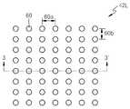
도 2는 패턴 조명 생성기(42)에 의해 생성된 패턴 조명의 일 예를 보여준다. 따라서 패턴 조명 생성기(42)에 의해 생성되는 패턴 조명은 도 2에 도시된 것으로 한정되지 않는다. 패턴 조명은 피사체에 도달되는 광의 광량분포가 일정하지 않은 조명으로써, 광량분포가 특정한 패턴을 이루는 조명일 수 있다.2 shows an example of pattern lighting generated by the
도 2를 참조하면, 패턴 조명(42L)은 복수의 스폿(spot)(60)을 포함한다. 복수의 스폿(60)은 격자 배열을 이룰 수 있다. 각 스폿(60)은 그 주변보다 광량이 많은 영역일 수 있다. 그러므로 각 스폿(60)의 광 에너지 밀도는 스폿(60)의 둘레보다 높다. 스폿(60)과 스폿(60)의 가로 간격(60a)과 세로 간격(60b)은 동일하거나 다를 수 있다.Referring to FIG. 2, the
도 3은 도 2를 3-3' 방향으로 절개한 단면을 보여준다.3 is a cross-sectional view of FIG. 2 taken in the direction 3-3'.
도 3을 참조하면, 3-3' 방향을 따른 광량분포는 주기적 패턴을 갖는 것을 알 수 있다. 도 3에서 광량분포가 상대적으로 많은 위치는 도 2의 스폿(60)의 위치에 대응되고, 광량분포가 상대적으로 적은 위치는 도 2의 스폿(60)과 스폿(60) 사이에 해당한다.Referring to FIG. 3, it can be seen that the light quantity distribution along the 3-3' direction has a periodic pattern. In FIG. 3, a location with a relatively large amount of light distribution corresponds to the location of the
도 2에 도시한 바와 같은 패턴조명(42L)을 피사체(44)에 조사하여 거리영상을 측정하는 경우, 스폿(60)의 광 에너지 밀도는 그 둘레보다 상대적으로 높기 때문에, 이미지 센서(50)에서 스폿(60)에 해당하는 신호의 크기는 상대적으로 커진다. 예컨대, 이미지 센서(50)에서 스폿(60)에 해당하는 신호의 세기는 그 둘레의 신호보다 4배 이상이 될 수 있다. 따라서 잡음광이 존재하는 환경에서도 스폿(60)에 해당하는 신호를 명확히 식별할 수 있는 바, 시간 비행(time of flight)법을 이용하여 이미지 센서(50)에 입사되는 스폿(60)에 해당하는 광의 위상 지연을 측정함으로써, 피사체(44)의 거리영상을 정확하게 측정할 수 있다. 피사체(44)의 스폿(60)과 스폿(60) 사이에 해당하는 영역의 거리영상에 대한 정보는 보간법(interpolation)을 이용하여 만들 수 있다. 그러므로 패턴조명(42L)에서 스폿(60)의 밀도가 높을 수록 피사체(44)에 대한 거리영상의 정밀도는 높아질 수 있다.When measuring a distance image by irradiating the pattern lighting 42L as shown in FIG. 2 on the subject 44, the light energy density of the
도 2의 패턴 조명(42L)을 생성하는 패턴 조명 생성기(42)는, 예를 들면 회절광학소자 또는 굴절광학소자일 수 있다. 상기 회절광학소자는 회절판일 수 있고, 그 구성은 얻고자 하는 패턴 조명을 생성하도록 설계될 수 있다. 그러므로 회절광학소자의 구성의 설계에 따라 스폿(60) 형태, 스폿(60) 사이즈, 스폿(60) 간격, 스폿(60)의 광량 집중 정도(광 에너지 밀도) 등이 다른 다양한 패턴 조명이 생성될 수 있다. 상기 굴절광학소자는 복수의 마이크로 렌즈를 포함할 수 있다. 상기 굴절광학소자는 마이크로 렌즈 어레이(array)일 수 있다. 마이크로 렌즈의 배열 형태 또는 마이크로 렌즈의 구성에 따라 스폿(60)의 형태, 사이즈, 간격 및/또는 에너지 밀도 등이 달라질 수 있다.The
도 4는 상기 회절광학소자와 상기 굴절광학소자의 일 예를 보여준다. 도 4에서 왼쪽은 상기 회절광학소자의 현미경 사진이고, 오른쪽은 상기 굴절광학소자(마이크로 렌즈 어레이)의 현미경 사진이다.4 shows an example of the diffractive optical device and the refractive optical device. In FIG. 4, a left side is a microscopic picture of the diffractive optical element, and a right side is a microscopic picture of the refractive optical element (micro lens array).
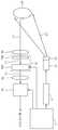
도 5는 본 발명의 실시예에 의한 거리영상 측정용 카메라의 보다 자세한 구성을 보여준다. 앞의 설명에서 언급된 참조번호와 동일한 참조번호는 동일한 부재를 나타낸다.5 shows a more detailed configuration of a camera for measuring a distance image according to an embodiment of the present invention. Reference numerals identical to reference numerals mentioned in the preceding description indicate identical members.
도 5를 참조하면, 본 발명의 일 실시예에 의한 카메라는 조명장치를 이루는 광원(40)과 패턴 조명 생성기(42), 광원 드라이버(72), 카메라 컨트롤러(74), 이미지 센서(50), 제1 및 제2 렌즈(46, 76), 필터기(48)를 포함할 수 있다. 필터기(48)는 필터(48a), 광 변조기(48b)를 포함할 수 있다. 제1 렌즈(46), 필터(48a), 광 변조기(48b), 제2 렌즈(76) 및 이미지 센서(50)는 일렬로 배열되고, 동일 광 축 상에 있을 수 있다. 광원(40)으로부터 피사체(44)에 광(L1)이 조사된다. 이 광(L1)은 상술한 패턴 조명을 갖는 것으로, 패턴 조명 생성기(42)를 거쳐 방출된 것이다. 광(L1)은 적외선으로, 파형은 펄스파 또는 사인파일 수 있다. 광원(40)은 광원 드라이버(72)에 의해 제어된다. 광원 드라이버(72)의 동작은 카메라 컨트롤러(74)에 의해 제어된다. 카메라 컨트롤러(74)는 광 변조기(48b)와 이미지 센서(50)의 동작을 제어한다. 제1 렌즈(46)는 피사체(44)로부터 반사되어 오는 광(L2)을 필터(48a)에 입사되기에 적합하게 모아준다. 필터(48a)는 광(L2) 중에서 광(L1)을 제외한 잡음광을 제거하기 위한 대역투과필터일 수 있다. 상기 대역투과필터는, 예를 들면 IR 대역 필터일 수 있다. 필터(48a)는 광 변조기(48b) 뒤에 배치될 수도 있다. 필터(48a)를 통과한 광(L3)은 광 변조기(48b)에 입사된다. 광 변조기(48b)는 본 발명이 속하는 기술분야에서 잘 알려진 광 변조기일 수도 있다. 광 변조기(48b)를 통과한 광(L4)은 제2 렌즈(76)를 거쳐 이미지 센서(50)에 입사된다. 제2 렌즈(76)는 광 변조기(48b)로부터 방출되는 광(L4)을 이미지 센서(50)로 집광시키는 역할을 한다. 이미지 센서(50)가 CCD일 때, 이미지 센서(50)는 카메라 컨트롤러(74)의 제어하에서 고속으로 누적 광량을 일정 주기 동안 적분하여 누적된 밝기영상을 컴퓨터로 출력하게 된다. 이러한 광 변조기(48b)를 이용한 거리영상 측정방법은 기존의 2차원 이미지 센서인 CCD와 CMOS를 활용할 수 있기 때문에, 고해상도의 거리영상을 획득하는데 유리할 수 있다.Referring to FIG. 5, the camera according to an embodiment of the present invention includes a
다음에는 도 6과 도 1을 참조하여 본 발명의 일 실시예에 의한 카메라의 거리영상 측정방법을 설명한다.Next, a method for measuring a distance image of a camera according to an embodiment of the present invention will be described with reference to FIGS. 6 and 1.
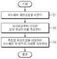
도 6을 참조하면, 먼저 피사체(44)에 패턴조명(L1)을 비춘다(S1).Referring to FIG. 6, first, pattern illumination L1 is illuminated on a subject 44 (S1).
제1 단계(S1)는 광원에서 광을 방출시키는 단계와 방출된 광을 패턴 조명으로 변화시키는 단계를 포함할 수 있다. 상기 광을 패턴 조명으로 변화시키는 단계는 회절광학소자 또는 굴절광학소자를 이용하여 상기 광원에서 방출된 광을 회절시키거나 굴절시키는 단계를 포함할 수 있다.The first step S1 may include emitting light from a light source and changing the emitted light into patterned lighting. The step of converting the light into patterned illumination may include diffracting or refracting the light emitted from the light source using a diffractive optical element or a refractive optical element.
다음, 피사체(44)로부터 반사된 광의 위상지연을 측정한다(S2).Next, the phase delay of the light reflected from the subject 44 is measured (S2).
상기 위상지연은 광원에서 방출된 광과 피사체로부터 반사된 광의 위상을 비교하여 측정할 수 있다. 상기 위상지연은 패턴조명(L1)의 스폿(60)에 해당하는 광의 위상지연이다. 제2 단계(S2)는 상기 위상 지연을 측정하기 전에, 피사체(44)로부터 반사된 광에서 잡음광을 줄이거나 제거하는 과정을 수행할 수 있다. 잡음광을 줄이거나 제거하는 과정은 필터기(48)를 이용하여 수행할 수 있다.The phase delay may be measured by comparing the phase of light emitted from a light source and light reflected from a subject. The phase delay is a phase delay of light corresponding to the
다음, 측정된 상기 위상지연을 이용하여 피사체(44)의 각 영역의 거리를 측정한다(S3).Next, the distance of each area of the subject 44 is measured using the measured phase delay (S3).
제3 단계(S3)에서 패턴조명(L1)의 스폿(60)에 대응하는 피사체(44)의 영역의 거리는 위상지연을 이용하여 측정하고, 스폿(60)과 스폿(60) 사이에 대응하는 피사체(44)의 영역의 거리는 보간법을 적용하여 측정할 수 있다.In the third step (S3), the distance of the area of the subject 44 corresponding to the
상기한 설명에서 많은 사항이 구체적으로 기재되어 있으나, 그들은 발명의 범위를 한정하는 것이라기보다, 바람직한 실시예의 예시로서 해석되어야 한다. 때문에 본 발명의 범위는 설명된 실시예에 의하여 정하여 질 것이 아니고 특허 청구범위에 기재된 기술적 사상에 의해 정하여져야 한다.Although many items are specifically described in the above description, they should be construed as examples of preferred embodiments rather than limiting the scope of the invention. Therefore, the scope of the present invention should not be determined by the described embodiments, but should be determined by the technical idea described in the claims.
30:조명장치 40:광원
42:패턴 조명 생성기 42L:패턴 조명
44:피사체46, 76:제1 및 제2 렌즈
48:필터기48a:대역투과필터(band pass filter)
48b:광 변조기 50:이미지 센서
60:스폿(spot) 60a:스폿의 가로간격
60b:스폿의 세로간격 72:광원 드라이버
74:카메라 컨트롤러 L1:피사체 입사광
L2:피사체 반사광
L3:필터를 통과하여 광 변조기에 입사되는 광
L4:광 변조기를 통과하여 제2 렌즈에 입사되는 광30: lighting device 40: light source
42:
44: subject 46, 76: first and second lenses
48:
48b: light modulator 50: image sensor
60:
60b: vertical spacing of spots 72: light source driver
74: camera controller L1: incident light of a subject
L2: Subject reflected light
L3: Light passing through the filter and incident on the optical modulator
L4: Light incident on the second lens through the light modulator
Claims (13)
Translated fromKorean피사체에 패턴조명을 비추는 조명장치;
상기 피사체로부터 반사되는 광에 포함된 잡음광을 줄이는 필터기; 및
상기 필터기를 통해 입사되는 광을 수광하여 상기 피사체에 대한 거리영상을 제공하는 이미지 센서;를 포함하고,
상기 필터기는 상기 피사체와 상기 이미지 센서 사이에 배치되고,
상기 필터기는,
대역투과필터(band pass filter); 및
광 변조기;를 포함하는, TOF 방식 거리영상 측정용 카메라.In the TOF method distance image measurement camera,
A lighting device that illuminates the pattern light on the subject;
A filter that reduces noise light included in light reflected from the subject; And
Includes; an image sensor that receives light incident through the filter and provides a distance image to the subject,
The filter is disposed between the subject and the image sensor,
The filter unit,
A band pass filter; And
Optical modulator; including, TOF method distance image measurement camera.
상기 조명장치는,
광원 및
상기 광원에서 방출되는 광을 상기 패턴조명으로 변화시키는 패턴 조명 생성기를 포함하는, TOF 방식 거리영상 측정용 카메라.The method of claim 1,
The lighting device,
Light source and
A camera for measuring distance image of a TOF method comprising a pattern lighting generator for changing the light emitted from the light source into the pattern lighting.
상기 패턴 조명 생성기는,
회절광학소자인 TOF 방식 거리영상 측정용 카메라.The method of claim 2,
The pattern lighting generator,
Diffraction optical element TOF type distance image measurement camera.
상기 패턴 조명 생성기는,
굴절광학소자인 TOF 방식 거리영상 측정용 카메라.The method of claim 2,
The pattern lighting generator,
Camera for measuring distance image of TOF method, which is a refractive optical device.
피사체에 패턴조명을 비추는 단계;
상기 피사체로부터 반사된 광의 위상지연을 측정하는 단계; 및
상기 측정된 위상지연을 이용하여 상기 피사체의 각 영역의 거리를 측정하는 단계;를 포함하는, TOF 방식 카메라를 이용한 거리영상 측정방법.In the distance image measurement method using the TOF method distance image measurement camera of claim 1,
Illuminating pattern lights on the subject;
Measuring a phase delay of light reflected from the subject; And
Measuring the distance of each area of the subject by using the measured phase delay; comprising, a distance image measuring method using a TOF type camera.
상기 피사체에 패턴조명을 비추는 단계는,
광원에서 광을 방출시키는 단계 및
상기 광원에서 방출된 광을 상기 패턴조명으로 변화시키는 단계를 포함하는, TOF 방식 카메라를 이용한 거리영상 측정방법.The method of claim 6,
The step of illuminating the pattern lighting on the subject,
Emitting light from a light source, and
A method for measuring a distance image using a TOF camera, comprising the step of changing the light emitted from the light source into the pattern illumination.
상기 광을 상기 패턴조명으로 변화시키는 단계는,
회절광학소자를 이용하여 상기 광을 회절시키는 단계를 포함하는, TOF 방식 카메라를 이용한 거리영상 측정방법.The method of claim 7,
The step of changing the light into the pattern lighting,
A method of measuring a distance image using a TOF camera, comprising diffracting the light using a diffractive optical element.
상기 광을 상기 패턴조명으로 변화시키는 단계는,
굴절광학소자를 이용하여 상기 광을 굴절시키는 단계를 포함하는, TOF 방식 카메라를 이용한 거리영상 측정방법.The method of claim 7,
The step of changing the light into the pattern lighting,
A method of measuring a distance image using a TOF camera, comprising the step of refracting the light using a refractive optical element.
상기 위상지연을 측정하는 단계는,
상기 피사체로부터 반사된 광에 포함된 잡음광을 줄이는 단계 및
상기 피사체로부터 반사된 광에 포함된 신호광의 위상지연을 측정하는 단계를 포함하는, TOF 방식 카메라를 이용한 거리영상 측정방법.The method of claim 6,
The step of measuring the phase delay,
Reducing noise light included in the light reflected from the subject, and
A method for measuring a distance image using a TOF camera, comprising measuring a phase delay of signal light included in light reflected from the subject.
상기 광원에서 방출된 광을 상기 패턴조명으로 변화시키는 단계는,
상기 광원에서 방출된 광을 광량이 상대적으로 많은 복수의 스폿(spot)을 포함하는 패턴 조명으로 변화시키는 단계를 포함하는, TOF 방식 카메라를 이용한 거리영상 측정방법.The method of claim 7,
The step of changing the light emitted from the light source into the pattern lighting,
A method for measuring a distance image using a TOF camera, comprising the step of changing the light emitted from the light source into pattern illumination including a plurality of spots having a relatively large amount of light.
상기 굴절광학소자로 마이크로 렌즈 어레이를 사용하는, TOF 방식 카메라를 이용한 거리영상 측정방법.The method of claim 9,
A method for measuring distance images using a TOF camera using a micro lens array as the refractive optical element.
상기 이미지 센서는,
상기 필터기를 통해 들어오는 광을 수신하고,
상기 수신된 광의 위상지연을 측정하고,
상기 측정된 위상지연에 기초해서 상기 카메라에서부터 상기 패턴조명에 포함된 스폿(spot)에 대응하는 상기 피사체의 제1 영역까지의 제1 거리를 측정하고,
내삽법(interpolation method)을 이용하여 상기 카메라에서부터 상기 패턴조명에 포함된 스폿 사이의 갭에 대응하는 상기 피사체의 제2 영역까지의 제2 거리를 측정하고, 및
상기 측정된 제1 및 제2 거리에 기초해서 상기 피사체의 거리영상을 제공하기 위해 마련된 이미지 센서인, TOF 방식 거리영상 측정용 카메라.The method of claim 1,
The image sensor,
Receiving light coming through the filter,
Measuring the phase delay of the received light,
A first distance from the camera to a first area of the subject corresponding to a spot included in the pattern lighting is measured based on the measured phase delay,
Measuring a second distance from the camera to a second area of the subject corresponding to a gap between spots included in the patterned illumination using an interpolation method, and
An image sensor provided to provide a distance image of the subject based on the measured first and second distances, a TOF method distance image measurement camera.
Priority Applications (3)
| Application Number | Priority Date | Filing Date | Title |
|---|---|---|---|
| KR1020130150839AKR102163728B1 (en) | 2013-12-05 | 2013-12-05 | Camera for depth image measure and method of measuring depth image using the same |
| US14/312,954US9781318B2 (en) | 2013-12-05 | 2014-06-24 | Camera for measuring depth image and method of measuring depth image using the same |
| US15/690,874US10097741B2 (en) | 2013-12-05 | 2017-08-30 | Camera for measuring depth image and method of measuring depth image using the same |
Applications Claiming Priority (1)
| Application Number | Priority Date | Filing Date | Title |
|---|---|---|---|
| KR1020130150839AKR102163728B1 (en) | 2013-12-05 | 2013-12-05 | Camera for depth image measure and method of measuring depth image using the same |
Publications (2)
| Publication Number | Publication Date |
|---|---|
| KR20150065473A KR20150065473A (en) | 2015-06-15 |
| KR102163728B1true KR102163728B1 (en) | 2020-10-08 |
Family
ID=53272440
Family Applications (1)
| Application Number | Title | Priority Date | Filing Date |
|---|---|---|---|
| KR1020130150839AActiveKR102163728B1 (en) | 2013-12-05 | 2013-12-05 | Camera for depth image measure and method of measuring depth image using the same |
Country Status (2)
| Country | Link |
|---|---|
| US (2) | US9781318B2 (en) |
| KR (1) | KR102163728B1 (en) |
Families Citing this family (73)
| Publication number | Priority date | Publication date | Assignee | Title |
|---|---|---|---|---|
| US8908995B2 (en) | 2009-01-12 | 2014-12-09 | Intermec Ip Corp. | Semi-automatic dimensioning with imager on a portable device |
| US9779546B2 (en) | 2012-05-04 | 2017-10-03 | Intermec Ip Corp. | Volume dimensioning systems and methods |
| US10007858B2 (en) | 2012-05-15 | 2018-06-26 | Honeywell International Inc. | Terminals and methods for dimensioning objects |
| US10321127B2 (en) | 2012-08-20 | 2019-06-11 | Intermec Ip Corp. | Volume dimensioning system calibration systems and methods |
| US9939259B2 (en) | 2012-10-04 | 2018-04-10 | Hand Held Products, Inc. | Measuring object dimensions using mobile computer |
| US20140104413A1 (en) | 2012-10-16 | 2014-04-17 | Hand Held Products, Inc. | Integrated dimensioning and weighing system |
| US9080856B2 (en) | 2013-03-13 | 2015-07-14 | Intermec Ip Corp. | Systems and methods for enhancing dimensioning, for example volume dimensioning |
| US10228452B2 (en) | 2013-06-07 | 2019-03-12 | Hand Held Products, Inc. | Method of error correction for 3D imaging device |
| US9464885B2 (en) | 2013-08-30 | 2016-10-11 | Hand Held Products, Inc. | System and method for package dimensioning |
| US9823059B2 (en) | 2014-08-06 | 2017-11-21 | Hand Held Products, Inc. | Dimensioning system with guided alignment |
| US9779276B2 (en) | 2014-10-10 | 2017-10-03 | Hand Held Products, Inc. | Depth sensor based auto-focus system for an indicia scanner |
| US10775165B2 (en) | 2014-10-10 | 2020-09-15 | Hand Held Products, Inc. | Methods for improving the accuracy of dimensioning-system measurements |
| US10810715B2 (en) | 2014-10-10 | 2020-10-20 | Hand Held Products, Inc | System and method for picking validation |
| US9752864B2 (en) | 2014-10-21 | 2017-09-05 | Hand Held Products, Inc. | Handheld dimensioning system with feedback |
| US10060729B2 (en) | 2014-10-21 | 2018-08-28 | Hand Held Products, Inc. | Handheld dimensioner with data-quality indication |
| US9762793B2 (en) | 2014-10-21 | 2017-09-12 | Hand Held Products, Inc. | System and method for dimensioning |
| US9897434B2 (en) | 2014-10-21 | 2018-02-20 | Hand Held Products, Inc. | Handheld dimensioning system with measurement-conformance feedback |
| US9557166B2 (en)* | 2014-10-21 | 2017-01-31 | Hand Held Products, Inc. | Dimensioning system with multipath interference mitigation |
| US9841496B2 (en)* | 2014-11-21 | 2017-12-12 | Microsoft Technology Licensing, Llc | Multiple pattern illumination optics for time of flight system |
| KR102305998B1 (en)* | 2014-12-08 | 2021-09-28 | 엘지이노텍 주식회사 | Image processing apparatus |
| US9786101B2 (en) | 2015-05-19 | 2017-10-10 | Hand Held Products, Inc. | Evaluating image values |
| US10066982B2 (en) | 2015-06-16 | 2018-09-04 | Hand Held Products, Inc. | Calibrating a volume dimensioner |
| US20160377414A1 (en) | 2015-06-23 | 2016-12-29 | Hand Held Products, Inc. | Optical pattern projector |
| US9857167B2 (en) | 2015-06-23 | 2018-01-02 | Hand Held Products, Inc. | Dual-projector three-dimensional scanner |
| US9835486B2 (en) | 2015-07-07 | 2017-12-05 | Hand Held Products, Inc. | Mobile dimensioner apparatus for use in commerce |
| EP3118576B1 (en) | 2015-07-15 | 2018-09-12 | Hand Held Products, Inc. | Mobile dimensioning device with dynamic accuracy compatible with nist standard |
| US10094650B2 (en) | 2015-07-16 | 2018-10-09 | Hand Held Products, Inc. | Dimensioning and imaging items |
| US20170017301A1 (en) | 2015-07-16 | 2017-01-19 | Hand Held Products, Inc. | Adjusting dimensioning results using augmented reality |
| CN106612387B (en)* | 2015-10-15 | 2019-05-21 | 杭州海康威视数字技术股份有限公司 | A kind of combined depth figure preparation method and depth camera |
| US10249030B2 (en) | 2015-10-30 | 2019-04-02 | Hand Held Products, Inc. | Image transformation for indicia reading |
| US10225544B2 (en) | 2015-11-19 | 2019-03-05 | Hand Held Products, Inc. | High resolution dot pattern |
| KR20170060353A (en) | 2015-11-24 | 2017-06-01 | 삼성전자주식회사 | Electronic apparatus, distance measurement sensor and control method for electronic apparatus and distance measurement sensor |
| CN105719254B (en)* | 2016-01-23 | 2020-02-21 | 深圳市云之梦科技有限公司 | A kind of image noise reduction method and system |
| US10025314B2 (en) | 2016-01-27 | 2018-07-17 | Hand Held Products, Inc. | Vehicle positioning and object avoidance |
| WO2017138033A1 (en)* | 2016-02-08 | 2017-08-17 | Denso Corporation | Time-of-flight distance measuring device and method for detecting multipath error |
| US10339352B2 (en) | 2016-06-03 | 2019-07-02 | Hand Held Products, Inc. | Wearable metrological apparatus |
| US9940721B2 (en) | 2016-06-10 | 2018-04-10 | Hand Held Products, Inc. | Scene change detection in a dimensioner |
| US10163216B2 (en) | 2016-06-15 | 2018-12-25 | Hand Held Products, Inc. | Automatic mode switching in a volume dimensioner |
| KR102746841B1 (en) | 2016-08-01 | 2024-12-27 | 엘지전자 주식회사 | Asymmetry optical sensor apparatus |
| EP3301477A1 (en)* | 2016-10-03 | 2018-04-04 | Xenomatix NV | System for determining a distance to an object |
| US10909708B2 (en) | 2016-12-09 | 2021-02-02 | Hand Held Products, Inc. | Calibrating a dimensioner using ratios of measurable parameters of optic ally-perceptible geometric elements |
| EP3343246A1 (en) | 2016-12-30 | 2018-07-04 | Xenomatix NV | System for characterizing surroundings of a vehicle |
| US11047672B2 (en) | 2017-03-28 | 2021-06-29 | Hand Held Products, Inc. | System for optically dimensioning |
| CN107289910B (en)* | 2017-05-22 | 2020-06-19 | 上海交通大学 | A TOF-based Optical Flow Localization System |
| US10733748B2 (en) | 2017-07-24 | 2020-08-04 | Hand Held Products, Inc. | Dual-pattern optical 3D dimensioning |
| DE102017219407A1 (en)* | 2017-10-27 | 2019-05-02 | Robert Bosch Gmbh | detection device |
| CN108200315A (en)* | 2017-12-29 | 2018-06-22 | 合肥泰禾光电科技股份有限公司 | A kind of depth camera and depth camera system |
| CN108279421B (en)* | 2018-01-28 | 2021-09-28 | 深圳新亮智能技术有限公司 | Time-of-flight camera with high resolution color images |
| CN110278426B (en)* | 2018-03-18 | 2024-02-13 | 宁波舜宇光电信息有限公司 | Depth information camera module, base assembly thereof, electronic equipment and preparation method |
| CN110285788B (en)* | 2018-03-19 | 2022-08-26 | 深圳光峰科技股份有限公司 | ToF camera and design method of diffractive optical element |
| US10972643B2 (en)* | 2018-03-29 | 2021-04-06 | Microsoft Technology Licensing, Llc | Camera comprising an infrared illuminator and a liquid crystal optical filter switchable between a reflection state and a transmission state for infrared imaging and spectral imaging, and method thereof |
| US10584962B2 (en) | 2018-05-01 | 2020-03-10 | Hand Held Products, Inc | System and method for validating physical-item security |
| US10924692B2 (en) | 2018-05-08 | 2021-02-16 | Microsoft Technology Licensing, Llc | Depth and multi-spectral camera |
| GB2579689A (en) | 2018-08-07 | 2020-07-01 | Cambridge Mechatronics Ltd | Improved 3D sensing |
| CN109005326B (en)* | 2018-08-30 | 2021-03-26 | Oppo广东移动通信有限公司 | Imaging devices and electronic equipment |
| CN109164432A (en)* | 2018-09-14 | 2019-01-08 | Oppo广东移动通信有限公司 | depth acquisition module and electronic device |
| CN109343070A (en)* | 2018-11-21 | 2019-02-15 | 深圳奥比中光科技有限公司 | Time flight depth camera |
| KR102040629B1 (en) | 2019-01-21 | 2019-11-05 | 경희대학교 산학협력단 | Depth Extraction Apparatus Using Camera |
| CN110024374B (en)* | 2019-02-27 | 2021-08-10 | 深圳市汇顶科技股份有限公司 | Imaging system, pixel array of imaging system and image sensor |
| US11698441B2 (en)* | 2019-03-22 | 2023-07-11 | Viavi Solutions Inc. | Time of flight-based three-dimensional sensing system |
| CN110196023B (en)* | 2019-04-08 | 2024-03-12 | 奥比中光科技集团股份有限公司 | Dual-zoom structured light depth camera and zooming method |
| CN110035269A (en)* | 2019-04-12 | 2019-07-19 | 信利光电股份有限公司 | A kind of bimodulus depth camera |
| KR102812099B1 (en)* | 2019-05-16 | 2025-05-23 | 엘지이노텍 주식회사 | Camera module |
| CN110415287B (en)* | 2019-07-11 | 2021-08-13 | Oppo广东移动通信有限公司 | Depth map filtering method, apparatus, electronic device and readable storage medium |
| GB2585952A (en)* | 2019-07-26 | 2021-01-27 | Cambridge Mechatronics Ltd | Method |
| US11639846B2 (en) | 2019-09-27 | 2023-05-02 | Honeywell International Inc. | Dual-pattern optical 3D dimensioning |
| CN110749916A (en)* | 2019-10-25 | 2020-02-04 | 上海联影医疗科技有限公司 | Method and device for acquiring time delay amount of PET detector crystal and computer equipment |
| KR102812092B1 (en)* | 2019-11-25 | 2025-05-23 | 엘지이노텍 주식회사 | Camera module |
| CN111007523A (en)* | 2019-12-09 | 2020-04-14 | Oppo广东移动通信有限公司 | Time-of-flight transmitters, time-of-flight depth modules and electronics |
| US10802066B1 (en)* | 2019-12-17 | 2020-10-13 | Quantum Valley Ideas Laboratories | Single-pixel imaging of electromagnetic fields |
| CN111538024B (en)* | 2020-03-24 | 2022-09-16 | 奥比中光科技集团股份有限公司 | Filtering ToF depth measurement method and device |
| US11722648B2 (en)* | 2020-07-07 | 2023-08-08 | Mirraviz, Inc. | Reflective display |
| US11867562B2 (en)* | 2022-01-25 | 2024-01-09 | Visera Technologies Company Limited | Optical devices |
Citations (3)
| Publication number | Priority date | Publication date | Assignee | Title |
|---|---|---|---|---|
| US20080240502A1 (en)* | 2007-04-02 | 2008-10-02 | Barak Freedman | Depth mapping using projected patterns |
| US20110310220A1 (en)* | 2010-06-16 | 2011-12-22 | Microsoft Corporation | Depth camera illuminator with superluminescent light-emitting diode |
| US20120229611A1 (en)* | 2011-03-07 | 2012-09-13 | Microsoft Corporation | Illuminator with refractive optical element |
Family Cites Families (12)
| Publication number | Priority date | Publication date | Assignee | Title |
|---|---|---|---|---|
| JP2002031516A (en) | 2000-07-18 | 2002-01-31 | Asahi Optical Co Ltd | 3D image input device |
| EP1305656A4 (en) | 2000-07-31 | 2006-03-08 | Rochester Photonics Corp | Structure screens for controlled spreading of light |
| US7108402B2 (en) | 2003-09-26 | 2006-09-19 | Tidal Photonics, Inc. | Apparatus and methods relating to precision control of illumination exposure |
| US7674019B2 (en) | 2007-08-11 | 2010-03-09 | Anthony, Inc. | Free-form lenses for rectangular illumination zones |
| WO2010021090A1 (en)* | 2008-08-20 | 2010-02-25 | パナソニック株式会社 | Distance estimating device, distance estimating method, program, integrated circuit, and camera |
| US8320621B2 (en) | 2009-12-21 | 2012-11-27 | Microsoft Corporation | Depth projector system with integrated VCSEL array |
| US9753128B2 (en)* | 2010-07-23 | 2017-09-05 | Heptagon Micro Optics Pte. Ltd. | Multi-path compensation using multiple modulation frequencies in time of flight sensor |
| KR101753312B1 (en)* | 2010-09-17 | 2017-07-03 | 삼성전자주식회사 | Apparatus and method for generating depth image |
| KR101686079B1 (en)* | 2010-12-27 | 2016-12-13 | 삼성전자주식회사 | Apparatus and method for generating depth image |
| KR101854188B1 (en)* | 2011-10-25 | 2018-05-08 | 삼성전자주식회사 | 3D image acquisition apparatus and method of acqiring depth information in the 3D image acquisition apparatus |
| JP5874325B2 (en)* | 2011-11-04 | 2016-03-02 | ソニー株式会社 | Image processing apparatus, image processing method, and program |
| EP2815251B1 (en)* | 2012-02-15 | 2017-03-22 | Heptagon Micro Optics Pte. Ltd. | Time of flight camera with stripe illumination |
- 2013
- 2013-12-05KRKR1020130150839Apatent/KR102163728B1/enactiveActive
- 2014
- 2014-06-24USUS14/312,954patent/US9781318B2/enactiveActive
- 2017
- 2017-08-30USUS15/690,874patent/US10097741B2/enactiveActive
Patent Citations (3)
| Publication number | Priority date | Publication date | Assignee | Title |
|---|---|---|---|---|
| US20080240502A1 (en)* | 2007-04-02 | 2008-10-02 | Barak Freedman | Depth mapping using projected patterns |
| US20110310220A1 (en)* | 2010-06-16 | 2011-12-22 | Microsoft Corporation | Depth camera illuminator with superluminescent light-emitting diode |
| US20120229611A1 (en)* | 2011-03-07 | 2012-09-13 | Microsoft Corporation | Illuminator with refractive optical element |
Also Published As
| Publication number | Publication date |
|---|---|
| US20150163474A1 (en) | 2015-06-11 |
| US20170366713A1 (en) | 2017-12-21 |
| US9781318B2 (en) | 2017-10-03 |
| US10097741B2 (en) | 2018-10-09 |
| KR20150065473A (en) | 2015-06-15 |
Similar Documents
| Publication | Publication Date | Title |
|---|---|---|
| KR102163728B1 (en) | Camera for depth image measure and method of measuring depth image using the same | |
| KR102486385B1 (en) | Apparatus and method of sensing depth information | |
| TWI862537B (en) | Three-dimensional sensor including bandpass filter having multiple passbands | |
| US10514148B2 (en) | Pattern projection using microlenses | |
| CN107783353B (en) | Apparatus and system for capturing stereoscopic images | |
| CN111263899B (en) | Lighting device, time-of-flight system and method | |
| US9958758B2 (en) | Multiple exposure structured light pattern | |
| KR102237828B1 (en) | Gesture detection device and detecting method of gesture using the same | |
| KR101925028B1 (en) | Apparatus and method of generating depth image | |
| US9599463B2 (en) | Object detection device | |
| US20120236288A1 (en) | Range Based Sensing | |
| US10408922B2 (en) | Optoelectronic module with low- and high-power illumination modes | |
| JP2022525894A (en) | Time-of-flight 3D sensing system | |
| KR20160057166A (en) | Camera for depth image measure and method of operating the same | |
| CA2762637A1 (en) | Device and method for obtaining three-dimensional object surface data | |
| KR20170050059A (en) | Method for generating depth image and image generating apparatus using thereof | |
| KR20140027815A (en) | 3d image acquisition apparatus and method of obtaining color and depth images simultaneously | |
| CN205787115U (en) | Photonic device | |
| KR20140137513A (en) | 3D image acquisition apparatus and method of driving the same | |
| US10151629B2 (en) | Spectral imaging sensors and methods with time of flight sensing | |
| JP7742364B2 (en) | Imaging method and imaging device | |
| RU2018116893A (en) | DEVICE, SYSTEM AND METHOD OF OBTAINING INFORMATION ABOUT THE Vital IMPORTANT FUNCTION OF A LIVING BEING | |
| KR102610830B1 (en) | Method and device for acquiring distance information | |
| TWI829828B (en) | Camera device | |
| KR102101865B1 (en) | Camera apparatus |
Legal Events
| Date | Code | Title | Description |
|---|---|---|---|
| PA0109 | Patent application | St.27 status event code:A-0-1-A10-A12-nap-PA0109 | |
| PG1501 | Laying open of application | St.27 status event code:A-1-1-Q10-Q12-nap-PG1501 | |
| PA0201 | Request for examination | St.27 status event code:A-1-2-D10-D11-exm-PA0201 | |
| D13-X000 | Search requested | St.27 status event code:A-1-2-D10-D13-srh-X000 | |
| D14-X000 | Search report completed | St.27 status event code:A-1-2-D10-D14-srh-X000 | |
| E902 | Notification of reason for refusal | ||
| PE0902 | Notice of grounds for rejection | St.27 status event code:A-1-2-D10-D21-exm-PE0902 | |
| E13-X000 | Pre-grant limitation requested | St.27 status event code:A-2-3-E10-E13-lim-X000 | |
| P11-X000 | Amendment of application requested | St.27 status event code:A-2-2-P10-P11-nap-X000 | |
| P13-X000 | Application amended | St.27 status event code:A-2-2-P10-P13-nap-X000 | |
| E701 | Decision to grant or registration of patent right | ||
| PE0701 | Decision of registration | St.27 status event code:A-1-2-D10-D22-exm-PE0701 | |
| PR0701 | Registration of establishment | St.27 status event code:A-2-4-F10-F11-exm-PR0701 | |
| PR1002 | Payment of registration fee | St.27 status event code:A-2-2-U10-U11-oth-PR1002 Fee payment year number:1 | |
| PG1601 | Publication of registration | St.27 status event code:A-4-4-Q10-Q13-nap-PG1601 | |
| PR1001 | Payment of annual fee | St.27 status event code:A-4-4-U10-U11-oth-PR1001 Fee payment year number:4 | |
| P22-X000 | Classification modified | St.27 status event code:A-4-4-P10-P22-nap-X000 | |
| PR1001 | Payment of annual fee | St.27 status event code:A-4-4-U10-U11-oth-PR1001 Fee payment year number:5 | |
| PR1001 | Payment of annual fee | St.27 status event code:A-4-4-U10-U11-oth-PR1001 Fee payment year number:6 |