KR102162562B1 - Refrigerant injection cooling jig for 3D printer - Google Patents
Refrigerant injection cooling jig for 3D printerDownload PDFInfo
- Publication number
- KR102162562B1 KR102162562B1KR1020190010886AKR20190010886AKR102162562B1KR 102162562 B1KR102162562 B1KR 102162562B1KR 1020190010886 AKR1020190010886 AKR 1020190010886AKR 20190010886 AKR20190010886 AKR 20190010886AKR 102162562 B1KR102162562 B1KR 102162562B1
- Authority
- KR
- South Korea
- Prior art keywords
- refrigerant
- cooling body
- cooling
- metal
- path
- Prior art date
- Legal status (The legal status is an assumption and is not a legal conclusion. Google has not performed a legal analysis and makes no representation as to the accuracy of the status listed.)
- Active
Links
Images


Classifications
- B22F3/1055—
- B—PERFORMING OPERATIONS; TRANSPORTING
- B22—CASTING; POWDER METALLURGY
- B22F—WORKING METALLIC POWDER; MANUFACTURE OF ARTICLES FROM METALLIC POWDER; MAKING METALLIC POWDER; APPARATUS OR DEVICES SPECIALLY ADAPTED FOR METALLIC POWDER
- B22F10/00—Additive manufacturing of workpieces or articles from metallic powder
- B22F10/20—Direct sintering or melting
- B22F10/25—Direct deposition of metal particles, e.g. direct metal deposition [DMD] or laser engineered net shaping [LENS]
- B—PERFORMING OPERATIONS; TRANSPORTING
- B22—CASTING; POWDER METALLURGY
- B22F—WORKING METALLIC POWDER; MANUFACTURE OF ARTICLES FROM METALLIC POWDER; MAKING METALLIC POWDER; APPARATUS OR DEVICES SPECIALLY ADAPTED FOR METALLIC POWDER
- B22F10/00—Additive manufacturing of workpieces or articles from metallic powder
- B22F10/20—Direct sintering or melting
- B22F10/22—Direct deposition of molten metal
- B—PERFORMING OPERATIONS; TRANSPORTING
- B22—CASTING; POWDER METALLURGY
- B22F—WORKING METALLIC POWDER; MANUFACTURE OF ARTICLES FROM METALLIC POWDER; MAKING METALLIC POWDER; APPARATUS OR DEVICES SPECIALLY ADAPTED FOR METALLIC POWDER
- B22F10/00—Additive manufacturing of workpieces or articles from metallic powder
- B22F10/70—Recycling
- B—PERFORMING OPERATIONS; TRANSPORTING
- B22—CASTING; POWDER METALLURGY
- B22F—WORKING METALLIC POWDER; MANUFACTURE OF ARTICLES FROM METALLIC POWDER; MAKING METALLIC POWDER; APPARATUS OR DEVICES SPECIALLY ADAPTED FOR METALLIC POWDER
- B22F12/00—Apparatus or devices specially adapted for additive manufacturing; Auxiliary means for additive manufacturing; Combinations of additive manufacturing apparatus or devices with other processing apparatus or devices
- B22F12/20—Cooling means
- B—PERFORMING OPERATIONS; TRANSPORTING
- B33—ADDITIVE MANUFACTURING TECHNOLOGY
- B33Y—ADDITIVE MANUFACTURING, i.e. MANUFACTURING OF THREE-DIMENSIONAL [3-D] OBJECTS BY ADDITIVE DEPOSITION, ADDITIVE AGGLOMERATION OR ADDITIVE LAYERING, e.g. BY 3-D PRINTING, STEREOLITHOGRAPHY OR SELECTIVE LASER SINTERING
- B33Y10/00—Processes of additive manufacturing
- B—PERFORMING OPERATIONS; TRANSPORTING
- B33—ADDITIVE MANUFACTURING TECHNOLOGY
- B33Y—ADDITIVE MANUFACTURING, i.e. MANUFACTURING OF THREE-DIMENSIONAL [3-D] OBJECTS BY ADDITIVE DEPOSITION, ADDITIVE AGGLOMERATION OR ADDITIVE LAYERING, e.g. BY 3-D PRINTING, STEREOLITHOGRAPHY OR SELECTIVE LASER SINTERING
- B33Y30/00—Apparatus for additive manufacturing; Details thereof or accessories therefor
- B—PERFORMING OPERATIONS; TRANSPORTING
- B33—ADDITIVE MANUFACTURING TECHNOLOGY
- B33Y—ADDITIVE MANUFACTURING, i.e. MANUFACTURING OF THREE-DIMENSIONAL [3-D] OBJECTS BY ADDITIVE DEPOSITION, ADDITIVE AGGLOMERATION OR ADDITIVE LAYERING, e.g. BY 3-D PRINTING, STEREOLITHOGRAPHY OR SELECTIVE LASER SINTERING
- B33Y40/00—Auxiliary operations or equipment, e.g. for material handling
- B33Y40/20—Post-treatment, e.g. curing, coating or polishing
- B22F2003/1058—
- Y—GENERAL TAGGING OF NEW TECHNOLOGICAL DEVELOPMENTS; GENERAL TAGGING OF CROSS-SECTIONAL TECHNOLOGIES SPANNING OVER SEVERAL SECTIONS OF THE IPC; TECHNICAL SUBJECTS COVERED BY FORMER USPC CROSS-REFERENCE ART COLLECTIONS [XRACs] AND DIGESTS
- Y02—TECHNOLOGIES OR APPLICATIONS FOR MITIGATION OR ADAPTATION AGAINST CLIMATE CHANGE
- Y02P—CLIMATE CHANGE MITIGATION TECHNOLOGIES IN THE PRODUCTION OR PROCESSING OF GOODS
- Y02P10/00—Technologies related to metal processing
- Y02P10/25—Process efficiency
Landscapes
- Engineering & Computer Science (AREA)
- Chemical & Material Sciences (AREA)
- Manufacturing & Machinery (AREA)
- Materials Engineering (AREA)
- Life Sciences & Earth Sciences (AREA)
- Sustainable Development (AREA)
- Mechanical Engineering (AREA)
Abstract
Translated fromKorean
Description
Translated fromKorean본 발명은 3D 프린터용 냉매 분사식 냉각지그에 관한 것으로서, 특히 기초 금속 적층물의 하부에서 냉매(냉각수)가 직접 접촉하도록 분사하는 냉각본체를 구비하여 금속의 적층시 냉매가 지속적으로 금속 적층물의 밑면에 분사되도록 함으로써, 3D 프린팅시 금속 적층물에 고온의 입열에너지가 신속하게 제거되어 변형을 방지하고 냉각속도 조절에 따른 금속조직을 미세화하는 3D 프린터용 냉매 분사식 냉각지그에 관한 것이다.The present invention relates to a refrigerant jet cooling jig for a 3D printer, and in particular, a cooling body that sprays coolant (coolant) directly into contact with a refrigerant (coolant) from a lower part of a base metal laminate, so that when metal is laminated, the refrigerant is continuously sprayed to the bottom of the metal laminate. By doing so, it relates to a refrigerant jet cooling jig for 3D printers that rapidly removes high-temperature heat input energy from a metal laminate during 3D printing to prevent deformation and refine a metal structure according to a cooling rate control.
일반적으로 잉크젯 프린터에서 쓰이는 것과 유사한 적층 방식으로 입체물을 제작하기 위해 3D 프린터(Three-Dimensional Printer)가 사용된다.In general, a 3D printer (Three-Dimensional Printer) is used to produce a three-dimensional object in a lamination method similar to that used in an inkjet printer.
이러한 3D 프린터는, 기계 절삭 및 성형 등 기존의 생산 방식을 탈피하여 일괄된 방식으로 어떤 형태의 제품도 만들어낼 수 있기 때문에 치과 등의 의료 분야는 물론, 각종 가정용품을 비롯해 자동차나 비행기 등에 쓰이는 기계장치도 생산이 가능하다.These 3D printers break away from the conventional production methods such as machine cutting and molding, and can create any type of product in a single way, so they are used not only in medical fields such as dentistry, but also in various household products, as well as machines used in automobiles and airplanes. Devices can also be produced.
그리고 3D 프린터는 작동 방식으로는 비교적 복잡한 모양을 만들 수 있고 제작과 채색을 동시에 진행할 수 있으며 가루나 액체를 굳혀가며 한층씩 쌓는 적층형과 커다란 합성수지를 둥근 날로 깎아가며 모양을 만드는 방식의 절삭형이 주로 사용되고 있다.In addition, the 3D printer can create a relatively complex shape, manufacture and color at the same time, and the lamination type in which powder or liquid is hardened and stacked one by one, and the cutting type in the method of shaping a large synthetic resin with a round blade. Is being used.
또, 3D 프린터는 선택적 레이저 소결(SLS : Selective Laser Sintering) 방식과 직접용착식(Direct Focused Deposition)이 대표적으로 사용되고 있다.In addition, as for 3D printers, selective laser sintering (SLS) and direct focused deposition are typically used.
여기서, 상기 선택적 레이저 소결 방식은 미세한 분말을 도포해 굳히는 방식으로 물체를 만드는 것이고, 직접용착식(Direct Focused Deposition)은 플라스틱 또는 금속 소재의 필라멘트를 열로 녹여 압출한 후 상온에서 굳혀 물체를 쌓아올리는 것이다.Here, the selective laser sintering method is to make an object by applying a fine powder to harden it, and the direct focused deposition method is to melt a filament of a plastic or metal material with heat, extrude it, and then harden it at room temperature to stack the object. .
그러나, 종래의 직접용착식(Direct Focused Deposition)의 3D 프린터는 고에너지의 열원을 기본으로 하기 때문에 연속된 적층작업시 누적되는 용접입열로 인해 적층물의 온도가 상승하는 것을 방지하도록 -45℃ 이하의 저온 아르곤 챔버(Argon chamber)를 사용하고 있는데 초기 투자 비용이 개략 4∼5억원의 높은 비용이 필요하므로 쉽게 채용하기 어려운 문제점이 있었다.However, since the conventional 3D printer of Direct Focused Deposition is based on a high-energy heat source, the temperature of the laminate is lowered to -45℃ to prevent the temperature of the laminate from rising due to the accumulated welding heat during continuous lamination. Although a low-temperature argon chamber is used, there is a problem that it is difficult to adopt easily because the initial investment cost is approximately 4 to 500 million won.
또, 종래의 직접용착식(Direct Focused Deposition)은 금속 적층물 간의 온도 유지를 위해 적층물을 냉각하는 휴식시간이 필요하게 되는데 이로 인해 작업이 지연되어 작업성이 저하되는 문제점이 있었다.In addition, in the conventional Direct Focused Deposition, a break for cooling the laminates is required in order to maintain the temperature between the metal laminates, which delays the work and reduces workability.
또한, 직접용착식(Direct Focused Deposition)에서 와이어 아크 적층 공법(wire arc additive manufacturing)은 용접로봇 시스템을 활용하기 때문에 중형 또는 대형 적층물을 작업시 전체 작업장을 저온 아르곤 챔버를 이용하여 아르곤 분위기로 만들기 위해서는 천문학적인 비용이 소요되기 때문에 중형이나 대형 적층물에는 실질적으로 사용이 어려운 문제점이 있었다.In addition, wire arc additive manufacturing in Direct Focused Deposition uses a welding robot system, so when working on medium or large laminates, the entire workplace is made into an argon atmosphere using a low temperature argon chamber. Because it requires astronomical cost, there is a problem that it is practically difficult to use for medium or large stacks.
이에, 본 발명은 상기한 문제점을 해결하기 위해 안출된 것으로서, 본 발명의 목적은 직접용착식(Direct Focused Deposition) 중 와이어 아크 적층 공법을 이용한 3D 프린팅 작업시 적은 비용으로 금속 적층물에 발생하는 고온의 입열 에너지가 신속하게 제거되어 변형을 방지하고 냉각속도조절에 따른 금속조직을 미세화하는 3D 프린터용 냉매 분사식 냉각지그를 제공하는 것이다.Accordingly, the present invention was conceived to solve the above problems, and the object of the present invention is to generate high temperature in metal laminates at a low cost during 3D printing using the wire arc lamination method among Direct Focused Deposition. It is to provide a refrigerant jet cooling jig for 3D printers that prevents deformation by quickly removing the heat input energy from and refines the metal structure according to the cooling rate control.
상기한 목적을 달성하기 위해 본 발명은 중앙을 기준으로 상면 가장자리 부분에 금속 적층물을 안착하기 위한 안착부가 형성되고, 상기 안착부의 하부에는 안착되는 금속 적층물을 지속적으로 냉각시키기 위해 냉매를 분사하기 위한 복수 개의 분사수단이 형성되며, 상기 안착부와 분사수단 사이에는 분사수단에 의해 냉매가 금속 적층물에 분사되어 열교환된 후 낙수되는 냉매를 수용하기 위한 넓이와 깊이를 갖는 냉매수용공간이 형성되는 냉각본체와, 상기 냉각본체에 냉매를 공급하기 위한 냉매 공급로와 열교환된 냉매를 회수하기 위한 냉매 회수로로 이루어지는 냉매 이동로와, 상기 냉매 이동로를 통해 냉각본체의 냉매 수용공간으로 냉매를 지속적으로 공급하기 위해 냉매를 저장하는 냉매저장탱크와, 열교환되어 회수되는 냉매를 냉각시키기 위한 냉각유닛으로 구성되는 냉각기를 포함하는 3D 프린터용 냉매 분사식 냉각지그에 있어서, 상기 냉각본체의 중앙부 상면으로는 냉매 이동로를 구성하는 냉매 공급로의 일단부분을 수용하기 위한 냉매 공급로 결합구멍이 형성된 덮개가 결합과 분리 가능하도록 형성되고, 냉각본체의 안착부 일 측에는 금속 적층물과 덮개를 견고하게 고정하기 위한 한 쌍의 클램프가 형성되며, 상기 냉매 수용공간의 타 일 측에는 냉각본체의 내부로 공급되는 냉매에 포함된 공기를 원활하게 배출시킬 수 있는 공기배출홀이 형성되는 것을 특징으로 한다.In order to achieve the above object, in the present invention, a seating portion for mounting a metal stack is formed at an edge of an upper surface with respect to the center, and spraying a coolant to continuously cool the metal stack seated at a lower portion of the seating portion. A plurality of spraying means are formed, and a refrigerant receiving space having a width and depth for receiving the refrigerant falling after heat exchange by spraying the refrigerant to the metal stack by the spraying means is formed between the seating part and the spraying means. A refrigerant transfer path consisting of a cooling body, a refrigerant supply path for supplying a refrigerant to the cooling body, and a refrigerant recovery path for recovering the heat-exchanged refrigerant, and a refrigerant continuously supplied to the refrigerant receiving space of the cooling body through the refrigerant transfer path. A refrigerant jet cooling jig for a 3D printer comprising a cooler comprising a refrigerant storage tank for storing refrigerant to be supplied to the refrigerant and a cooling unit for cooling the refrigerant recovered through heat exchange, wherein a refrigerant is provided on an upper surface of a central portion of the cooling body A cover with a coupling hole is formed to be coupled and detachable from a refrigerant supply path for accommodating one end of the refrigerant supply path constituting the moving path, and a metal stack and a cover are firmly fixed to one side of the seating part of the cooling body. A pair of clamps are formed, and an air discharge hole through which air contained in the refrigerant supplied to the inside of the cooling body is smoothly discharged is formed on the other side of the refrigerant accommodation space.
삭제delete
삭제delete
상기 냉각본체의 상면에는 금속 적층물과 덮개가 고정된 부분에서 냉매의 누출(Leakage)을 방지하기 위해 복수 개의 실(seal)이 형성되는 것을 특징으로 한다.A plurality of seals are formed on the upper surface of the cooling body to prevent leakage of refrigerant at a portion where the metal stack and the cover are fixed.
삭제delete
삭제delete
상기 냉매 공급로는 냉각본체의 중앙으로 연결되는 것이 바람직하고, 상기 냉매 회수로는 냉각본체의 냉매 수용공간으로 연결되는 것을 특징으로 한다.The refrigerant supply path is preferably connected to the center of the cooling body, and the refrigerant recovery path is connected to a refrigerant receiving space of the cooling body.
삭제delete
삭제delete
삭제delete
이상에서와 같은 본 발명은 직접 용착식의 와이어 아크 적층 공법을 이용한 3D 프린팅 작업시 적은 비용으로 금속 적층물의 밑면에 지속적으로 냉매가 분사되도록 함으로써 비용절감을 이룸과 동시에 중형과 대형 적층물도 실질적으로 사용할 수 있으며, 변형문제 최소화를 통한 품질 향상을 이루는 효과가 있다.The present invention as described above achieves cost reduction by continuously spraying the refrigerant onto the underside of the metal stack at a low cost during 3D printing using the direct welding wire arc lamination method, and at the same time, it is practically used for medium and large stacks. It can be, and there is an effect of achieving quality improvement by minimizing deformation problems.
또, 본 발명은 냉각속도 조절을 통한 적층 금속부의 미세조직을 미세화하는 효과가 있다.In addition, the present invention has the effect of miniaturizing the microstructure of the laminated metal portion by controlling the cooling rate.
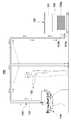
도 1은 본 발명의 바람직한 실시예에 따른 3D 프린터용 냉매 분사식 냉각지그의 전체 구성을 개략적으로 나타낸 도면이다.
도 2는 본 발명에 따른 냉각본체와 냉매 이동로의 일부를 분해한 요부 단면도이다.
도 3은 도 2의 결합 상태를 나타낸 도면이다.
도 4는 덮개를 제거한 냉각본체의 단면 확대도이다.
도 5는 본 발명에 따른 냉각본체의 평면도이다.
도 6은 본 발명의 바람직한 실시예에 따른 3D 프린터용 냉매 분사식 냉각지그의 사용 상태를 개략적으로 나타낸 도면이다.
도 7은 도 6의 냉각본체 부분을 확대하여 나타낸 도면이다.1 is a view schematically showing the overall configuration of a refrigerant jet cooling jig for a 3D printer according to a preferred embodiment of the present invention.
2 is a cross-sectional view illustrating a part of a cooling body and a refrigerant passage according to the present invention.
3 is a view showing a combined state of FIG. 2.
4 is an enlarged cross-sectional view of the cooling body with the cover removed.
5 is a plan view of a cooling body according to the present invention.
6 is a view schematically showing a state of use of a refrigerant jet cooling jig for a 3D printer according to a preferred embodiment of the present invention.
7 is an enlarged view of the cooling body portion of FIG. 6.
이하, 본 발명에 따른 바람직한 실시예를 첨부된 도면에 의거하여 보다 구체적으로 설명한다.Hereinafter, a preferred embodiment according to the present invention will be described in more detail with reference to the accompanying drawings.
여기서, 하기의 모든 도면에서 동일한 기능을 갖는 구성요소는 동일한 참조부호를 사용하여 반복적인 설명은 생략하며, 아울러 후술 되는 용어들은 본 발명에서의 기능을 고려하여 정의된 것으로서, 이것은 고유의 통용되는 의미로 해석되어야 함을 명시한다.Here, elements having the same function in all of the drawings below are omitted by using the same reference numerals, and repetitive descriptions are omitted, and terms to be described later are defined in consideration of functions in the present invention, and this is a unique and commonly used meaning Specifies that it should be interpreted as.
도 1 내지 도 7에 도시된 바와 같이 본 발명은 냉각본체(110)와 냉매 이동로(120) 및 냉각기(130)로 대별되어 이루어진다.1 to 7, the present invention is roughly divided into a
상기 냉각본체(110)는 중앙을 기준으로 상면 가장자리 부분에 금속 적층물(200)을 안착하기 위한 안착부(111)가 형성되고, 상기 안착부(111)의 하부에는 안착되는 금속 적층물(200)을 지속적으로 냉각시키기 위해 냉매를 금속 적층물(200)에 분사하기 위한 복수 개의 분사수단(112)이 형성된다.The
여기서, 상기 분사수단(112)은 유로(112a)와 노즐(nozzle : 액체 또는 기체를 고속으로 자유공간에 분출시키기 위해 유로 끝에 다는 가는 관.)(112b)로 구성되는 것이 바람직하다.Here, the injection means 112 is preferably composed of a flow path (112a) and a nozzle (nozzle: a thin tube attached to the end of the flow path to eject a liquid or gas into the free space at high speed) (112b).
그러나 상기 분사수단(112)은 이에 한정되지 않고 유로(112a)와 스프링클러(sprinkler : 살수기)(112b)로 형성될 수도 있다.However, the spraying means 112 is not limited thereto and may be formed of a
이러한 구성의 상기 분사수단(112)은 냉각본체(110)의 안착부(111)에 안착되는 금속 적층물(200)의 밑면에 냉매를 직접 분사시킴으로써 3D 프린팅 적용시 금속 적층물(200)을 신속하게 냉각시켜 고온의 입열에너지 누적과 온도 상승을 방지함과 동시에 기초 금속 적층물(200)의 두께가 얇더라도 용접적층으로 인한 변형을 방지할 수 있다.The spraying means 112 of this configuration directly injects a refrigerant onto the bottom of the
또, 상기 냉각본체(110)의 안착부(111)와 분사수단(112) 사이에는 상기 분사수단(112)에 의해 냉매가 금속 적층물(200)에 분사되어 열교환된 후 낙수되는 냉매를 수용하기 위한 넓이와 깊이를 갖는 냉매 수용공간(113)이 형성된다.In addition, between the
또한, 상기 분사수단(112)은 금속 적층물(200)의 밑면에 냉매를 직접 분사시킴으로써 냉각효율을 높여 얇은 기초 금속 적층물(200)의 변형도 완벽하게 방지함으로써 접촉식 냉각지그와 달리 냉매를 회수하는 냉매 수용공간(113)의 밀폐를 견고하고 원활하게 하여 냉매가 밖으로 분출되는 것을 방지할 수 있다.In addition, the spraying means 112 improves cooling efficiency by directly injecting the refrigerant onto the bottom of the
그리고, 상기 냉각본체(110)의 중앙 부분 아래측에는 상기 분사수단(112)으로 냉매를 공급하기 위한 냉매 공급공간(114)이 형성된다.Further, a
상기 냉매 공급공간(114)을 냉각본체(110)의 아래측에 형성하는 이유는 냉매를 상기 금속 적층물(200)의 밑면으로 원활하게 공급하기 위해서이다.The reason why the
또, 상기 냉각본체(110)의 중앙부 상면으로는 추후 설명할 냉매 이동로(120)를 구성하는 냉매 공급로(121)의 일단부분을 수용하기 위한 냉매 공급로 결합구멍(115a)이 형성된 덮개(115)가 결합과 분리 가능하도록 형성된다.In addition, a cover formed with a refrigerant supply
또한, 상기 냉각본체(110)의 안착부(111)에는 금속 적층물(200)과 덮개(115)를 견고하게 고정하기 위한 한 쌍의 클램프(116)가 결합, 형성된다.In addition, a pair of
여기서, 상기 각 클램프(116)는 볼트와 같은 체결수단(TM)을 포함하여 이루어지고, 상기 냉각본체(110)의 안착부(111)에는 상기 체결수단(TM)을 수용하기 위한 체결구멍(미도시)이 형성된다.Here, each of the
또한, 상기 냉각본체(110)의 상면에는 금속 적층물(200)과 덮개(115)가 고정된 부분에서 냉매의 누출(Leakage)을 방지하기 위해 복수 개의 실(seal)(117)이 형성된다..In addition, a plurality of
그리고, 상기 냉각본체(110)에 형성된 냉매 수용공간(113)의 일측으로는 이하에서 설명할 상기 냉매 회수로(122)와 연결을 위한 회수로 결합구멍(113a)이 형성된다.Further, at one side of the
또, 상기 냉매 수용공간(113)의 타 일 측에는 냉각본체(110)의 내부로 공급되는 냉매에 포함된 공기를 원활하게 배출시킬 수 있는 공기배출홀(113b)이 형성되는 것이 바람직하다.In addition, it is preferable that an
상기 냉매 이동로(120)는 상기 냉각본체(110)에 냉매를 공급하기 위한 냉매 공급로(121)와 열교환된 냉매를 회수하기 위한 냉매 회수로(122)로 이루어진다.The
여기서, 상기 냉매 공급로(121)의 일단부분은 냉각본체(110)의 중앙으로 형성되는 냉매 공급공간(114)과 연결되는 것이 바람직하고, 상기 냉매 회수로(122)의 일단부분은 냉각본체(110)의 냉매 수용공간(113)에 형성된 회수로 결합구멍(113a)으로 연결되는 것이 바람직하다.Here, one end of the
그 이유는 상기 냉매 공급로(121)를 냉각본체(110)의 중앙으로 연결하는 것이 가장자리 측으로 형성되는 금속 적층물(200)의 하부로 냉매의 열손실을 최소화 하면서 공급할 수 있고, 반대로 상기 냉매 회수로(122)를 냉매 수용공간(113)의 일측으로 연결하는 것이 열교환된 냉매를 즉시 원활하게 회수할 수 있다.The reason is that connecting the
그리고, 상기 냉매 이동로(120)의 일 측에는 추후 설명할 냉각기(130)의 냉매저장탱크(131)에 저장된 냉매를 냉매 공급로(121)를 통해 냉매저장탱크(131)로 강제 순환시키기 위한 순환팬(미도시)이 설치되고, 상기한 순환팬은 냉매저장탱크(131)의 타일측에 설치된 모터(미도시)에 의하여 회전하도록 구성된다.In addition, a circulation for forcibly circulating the refrigerant stored in the
이러한 구성의 상기 냉매 이동로(120)는 냉매의 열손실을 최소화 하면서 공급과 회수를 지속적으로 이룰 수 있다.The
상기 냉각기(130)는 냉매 이동로(120)를 통해 냉각본체(110)의 냉매 수용공간(112)으로 냉매를 지속적으로 공급하기 위해 냉매를 저장하는 냉매저장탱크(131)와, 열교환되어 회수되는 냉매를 냉각시키기 위한 냉각유닛(132)으로 구성된다.The cooler 130 includes a
상기 냉매저장탱크(131)의 일측 상,하부에는 냉매를 냉각본체(110)로 순환시키기 위한 냉매 유입구(131a)와 냉매 유출구(131b)가 형성 되어 있다.A
상기 냉매저장탱크(131)의 냉매 유출구(131b)와 덮개(114)에 형성된 냉매 공급로 결합구멍(114a)은 상기 냉매 이동로(120)를 구성하는 냉매 공급로(121)와 연결된다.The
그리고, 상기 냉매저장탱크(131)의 냉매 유입구(131a)와 냉각본체(110)의 냉매 수용공간(112)에 형성된 냉매 회수로 결합구멍(112a)은 상기 냉매 이동로(120)를 구성하는 냉매 회수로(122)와 연결된다.In addition, the refrigerant inlet (131a) of the refrigerant storage tank (131) and the refrigerant recovery path coupling hole (112a) formed in the refrigerant receiving space (112) of the cooling body (110) is a refrigerant constituting the refrigerant transfer path (120). It is connected to the
이에 따라, 상기 냉매저장탱크(131)에 저장되어 있는 냉매는 냉매 이동로(120)를 통해 냉각본체(110)로 공급되어 열교환작용을 한 후 냉매 회수로(122)를 통해 냉매저장탱크(131)로 회수되는 순환작동을 반복하게 된다.Accordingly, the refrigerant stored in the
상기 냉각유닛(132)은 냉매저장탱크(131)의 외부에서 제작된 후 냉매저장탱크(131)에 삽입 설치되는 것으로서, 상기 냉각유닛(132)은 경량재이고 열전도율이 우수한 알루미늄 재질로서 두께는 얇고 양측면의 상,하 폭은 넓고 긴 길이로 형성된 판형의 냉각판(132a)들이 종횡으로 다수열 설치된 구조로서 냉매저장탱크(131)에 저장되어 있는 냉매를 차갑게 냉각시키는 것이다.The
한편, 도면에 도시하지 않았지만 냉매저장탱크(131)의 상단 일측에는 냉매를 보충하기 위한 보충수 공급라인(미도시)이 설치되어 있어 냉매저장탱크(131)에 저장되는 냉매를 항시 적정수위로 유지시킬 수 있다.On the other hand, although not shown in the drawing, a make-up water supply line (not shown) for replenishing the refrigerant is installed on one side of the upper end of the
또, 본 발명은 상기 냉매 분사식 냉각지그(100)를 구비하는 3D 프린터(미도시)를 더 제공한다.In addition, the present invention further provides a 3D printer (not shown) including the refrigerant
상기와 같이 구성된 본 발명의 사용 상태를 설명하면 다음과 같다.The state of use of the present invention configured as described above is as follows.
먼저, 본 발명에 따른 냉매 분사식 냉각지그가 제공된 3D 프린터(미도시)를 이용하여 금속을 적층하고자 할 경우, 상기 냉각본체(110)의 안착부(111)에 기초를 형성하는 금속 적층물(200)을 안착시킨다.First, when metal is to be laminated using a 3D printer (not shown) provided with a refrigerant jet cooling jig according to the present invention, a
다음, 상기 클램프(116)와 볼트와 같은 체결수단(TM)을 이용하여 기초를 형성하는 금속 적층물(200)을 견고하게 고정한다.Next, the
그리고 상기 기초를 형성하는 금속 적층물(200)의 상면으로 다른 금속 적층물(200)을 적층하도록 용접작업을 진행한다.Then, a welding operation is performed to stack another
이와 동시에 상기 냉매저장탱크(131)의 일 측에 설치된 모터(미도시)를 동작시키면 순환팬(미도시)이 구동하면서 냉매는 냉매 공급로(121)를 통해 냉각본체(110)의 냉매 공급공간(114)으로 공급된 후, 상기 분사수단(112)을 통해 기초를 형성하는 금속 적층물(200)의 밑면으로 분사된다.At the same time, when a motor (not shown) installed on one side of the
이에 따라, 상기 금속 적층물(200)은 분사된 냉매에 의해 금속 적층물(200)의 적층시 발생하는 고온의 입열 에너지인 용접입열(welding heat input : 용접부에 외부로부터 주어지는 열량)에 의한 온도를 냉각시키게 된다.Accordingly, the
그리고, 상기 기초를 형성하는 금속 적층물(200)과 직접 접촉하면서 열교환된 냉매는 냉매 수용공간(113)으로 낙하된 후 상기 냉매 회수로(122)를 통해 다시 냉매저장탱크(131)로 회수된다.In addition, the refrigerant heat-exchanged while directly in contact with the
즉, 상기 냉각기(130)가 동작하면서 모터와 순환팬에 의해 냉매는 냉매 공급로(121)와 분사수단(112)을 통해 냉각본체(110)에 안착되는 금속 적층물(200)의 밑면에 직접 분사되어 열교환작용을 한 후, 냉매 회수로(122)를 통해 냉매저장탱크(131)로 회수되는 순환작동을 반복하게 된다.That is, while the cooler 130 is operating, the refrigerant is directly on the bottom of the
이와 같이 상기 냉각본체(110)를 통해 금속 적층물(200)의 밑면에 냉매를 직접 분사시켜 열교환을 이루도록 함으로써 신속한 열교환으로 열교환효율이 매우 뛰어나기 때문에 저렴한 비용으로 종래에 비해 월등한 냉각효율 향상을 이룰 수 있다.In this way, the refrigerant is directly injected to the bottom of the
따라서 본 발명은 이와 같은 동작을 지속적으로 반복함으로써 3D 프린터의 프린팅 작업시 금속 적층물의 고온의 입열 에너지로 인한 온도 상승을 방지함과 동시에 용접변형을 예방할 수 있는 것이다.Accordingly, the present invention can prevent an increase in temperature due to high-temperature heat input energy of a metal laminate during a printing operation of a 3D printer by continuously repeating such an operation and at the same time prevent welding deformation.
이상에서 설명한 본 발명은 전술한 실시예 및 첨부된 도면에 의해 한정되는 것이 아니고, 본 발명의 기술적 사상을 벗어나지 않는 범위 내에서 여러 가지로 치환, 변형 및 균등한 타 실시예로의 변경이 가능함은 본 발명이 속하는 기술분야에서 통상의 지식을 가진 자에게 있어서 명백할 것이다.The present invention described above is not limited by the above-described embodiments and the accompanying drawings, and various substitutions, modifications, and changes to other equivalent embodiments are possible within the scope of the technical spirit of the present invention. It will be apparent to those of ordinary skill in the art to which the present invention pertains.
100 : 냉매 분사식 냉각지그 110 : 냉각본체
111 : 안착부 112 : 분사수단
112a : 유로 112b : 노즐
113 : 냉매 수용공간 113a : 회수로 결합구멍
114 : 냉매 공급공간 114a : 냉매 공급유로
115 : 덮개 115a : 냉매 공급로 결합구멍
116 : 클램프 117 : 실(seal)
120 : 냉매 이동로 121 : 냉매 공급로
122 : 냉매 회수로 130 : 냉각기
131 : 냉매저장탱크 131a : 냉매 유입구
131b : 냉매 유출구 132 : 냉각유닛
132a : 냉각판 200 : 금속 적층물100: refrigerant injection cooling jig 110: cooling body
111: seat 112: spraying means
112a: flow
113:
114:
115: cover 115a: refrigerant supply path coupling hole
116: clamp 117: seal
120: refrigerant moving path 121: refrigerant supply path
122: refrigerant recovery furnace 130: cooler
131:
131b: refrigerant outlet 132: cooling unit
132a: cooling plate 200: metal laminate
Claims (10)
Translated fromKorean상기 냉각본체의 중앙부 상면으로는 냉매 이동로를 구성하는 냉매 공급로의 일단부분을 수용하기 위한 냉매 공급로 결합구멍이 형성된 덮개가 결합과 분리 가능하도록 형성되고, 냉각본체의 안착부 일 측에는 금속 적층물과 덮개를 견고하게 고정하기 위한 한 쌍의 클램프가 형성되며, 상기 냉매 수용공간의 타 일 측에는 냉각본체의 내부로 공급되는 냉매에 포함된 공기를 원활하게 배출시킬 수 있는 공기배출홀이 형성되는 것을 특징으로 하는 3D 프린터용 냉매 분사식 냉각지그.A seating portion for mounting the metal stack is formed at the edge of the upper surface with respect to the center, and a plurality of spraying means for injecting a refrigerant to continuously cool the seated metal stack are formed in the lower portion of the seating portion. A cooling body in which a refrigerant receiving space having a width and depth for receiving the refrigerant falling after heat exchange by spraying the refrigerant to the metal stack by the spraying means is formed between the seating portion and the spraying means, and a refrigerant in the cooling body. A refrigerant transfer path comprising a refrigerant supply path for supply and a refrigerant recovery path for recovering heat exchanged refrigerant, and a refrigerant storage for storing refrigerant to continuously supply refrigerant to the refrigerant receiving space of the cooling body through the refrigerant transfer path. In the refrigerant jet cooling jig for a 3D printer comprising a cooler comprising a tank and a cooling unit for cooling the refrigerant recovered by heat exchange,
On the upper surface of the central portion of the cooling body, a cover formed with a refrigerant supply path coupling hole for accommodating one end of the refrigerant supply path constituting the refrigerant passage is formed to be coupled and detachable, and a metal stacked on one side of the seating portion of the cooling body A pair of clamps for firmly fixing the water and the cover are formed, and an air discharge hole is formed on the other side of the refrigerant receiving space to smoothly discharge the air contained in the refrigerant supplied to the inside of the cooling body. Refrigerant jet cooling jig for 3D printer, characterized in that.
상기 냉각본체의 상면에는 금속 적층물과 덮개가 고정된 부분에서 냉매의 누출(Leakage)을 방지하기 위해 복수 개의 실(seal)이 형성되는 것을 특징으로 하는 3D 프린터용 냉매 분사식 냉각지그.The method of claim 3,
A refrigerant jet cooling jig for a 3D printer, characterized in that a plurality of seals are formed on the upper surface of the cooling body to prevent leakage of refrigerant at a portion in which the metal stack and the cover are fixed.
상기 냉매 공급로는 냉각본체의 중앙으로 연결되는 것이 바람직하고, 상기 냉매 회수로는 냉각본체의 냉매 수용공간으로 연결되는 것을 특징으로 하는 3D 프린터용 냉매 분사식 냉각지그.The method of claim 3,
The refrigerant supply path is preferably connected to the center of the cooling body, and the refrigerant recovery path is connected to a refrigerant accommodation space of the cooling body.
Priority Applications (1)
| Application Number | Priority Date | Filing Date | Title |
|---|---|---|---|
| KR1020190010886AKR102162562B1 (en) | 2019-01-29 | 2019-01-29 | Refrigerant injection cooling jig for 3D printer |
Applications Claiming Priority (1)
| Application Number | Priority Date | Filing Date | Title |
|---|---|---|---|
| KR1020190010886AKR102162562B1 (en) | 2019-01-29 | 2019-01-29 | Refrigerant injection cooling jig for 3D printer |
Publications (2)
| Publication Number | Publication Date |
|---|---|
| KR20200101492A KR20200101492A (en) | 2020-08-28 |
| KR102162562B1true KR102162562B1 (en) | 2020-10-07 |
Family
ID=72265938
Family Applications (1)
| Application Number | Title | Priority Date | Filing Date |
|---|---|---|---|
| KR1020190010886AActiveKR102162562B1 (en) | 2019-01-29 | 2019-01-29 | Refrigerant injection cooling jig for 3D printer |
Country Status (1)
| Country | Link |
|---|---|
| KR (1) | KR102162562B1 (en) |
Citations (6)
| Publication number | Priority date | Publication date | Assignee | Title |
|---|---|---|---|---|
| US20030145445A1 (en) | 2000-05-15 | 2003-08-07 | Claude Barlier | Device for producing plates designed for a fast prototyping process, method for machining and assembling said plates and resulting plates and prototype workpieces |
| JP2008307895A (en) | 2007-05-14 | 2008-12-25 | Panasonic Electric Works Co Ltd | Manufacturing method and manufacturing apparatus for three-dimensional shaped object |
| JP2011202202A (en) | 2010-03-24 | 2011-10-13 | Mitsubishi Materials Corp | Method for producing metal sintered compact and production device therefor |
| KR101372839B1 (en) | 2013-08-26 | 2014-03-12 | 공주대학교 산학협력단 | Method and apparatus for manufacturing powders |
| KR101825319B1 (en) | 2017-01-18 | 2018-02-02 | 박현우 | Cooling apparatus for output of 3d printer |
| WO2018130949A1 (en) | 2017-01-10 | 2018-07-19 | Ecole Polytechnique Federale De Lausanne (Epfl) | Cryogel 3d scaffolds and methods for producing thereof |
Family Cites Families (9)
| Publication number | Priority date | Publication date | Assignee | Title |
|---|---|---|---|---|
| US4998413A (en)* | 1988-09-01 | 1991-03-12 | Nippondenso Co., Ltd. | Refrigerant recovery system |
| JPH07153883A (en)* | 1993-11-26 | 1995-06-16 | Ngk Spark Plug Co Ltd | Electronic component cooling apparatus |
| KR20070014877A (en)* | 2005-07-29 | 2007-02-01 | 삼성전자주식회사 | Chiller for Semiconductor Manufacturing Equipment |
| KR101076353B1 (en)* | 2006-08-28 | 2011-10-25 | 파나소닉 전공 주식회사 | Metal powder for metal-laser sintering and metal-laser sintering process using the same |
| KR20150063827A (en)* | 2013-12-02 | 2015-06-10 | 삼성전기주식회사 | Cooling system for power semiconductor module |
| US10478188B2 (en)* | 2015-09-30 | 2019-11-19 | Ethicon Llc | Implantable layer comprising a constricted configuration |
| KR101733884B1 (en)* | 2015-10-14 | 2017-05-24 | 이수연 | 3d printer |
| KR101760832B1 (en) | 2015-11-23 | 2017-07-24 | 옥은택 | Cooling system for 3d printer using arc welding |
| KR101918947B1 (en)* | 2017-01-17 | 2018-11-15 | 주식회사 동구전자 | Cooling device for beverage dispenser |
- 2019
- 2019-01-29KRKR1020190010886Apatent/KR102162562B1/enactiveActive
Patent Citations (6)
| Publication number | Priority date | Publication date | Assignee | Title |
|---|---|---|---|---|
| US20030145445A1 (en) | 2000-05-15 | 2003-08-07 | Claude Barlier | Device for producing plates designed for a fast prototyping process, method for machining and assembling said plates and resulting plates and prototype workpieces |
| JP2008307895A (en) | 2007-05-14 | 2008-12-25 | Panasonic Electric Works Co Ltd | Manufacturing method and manufacturing apparatus for three-dimensional shaped object |
| JP2011202202A (en) | 2010-03-24 | 2011-10-13 | Mitsubishi Materials Corp | Method for producing metal sintered compact and production device therefor |
| KR101372839B1 (en) | 2013-08-26 | 2014-03-12 | 공주대학교 산학협력단 | Method and apparatus for manufacturing powders |
| WO2018130949A1 (en) | 2017-01-10 | 2018-07-19 | Ecole Polytechnique Federale De Lausanne (Epfl) | Cryogel 3d scaffolds and methods for producing thereof |
| KR101825319B1 (en) | 2017-01-18 | 2018-02-02 | 박현우 | Cooling apparatus for output of 3d printer |
Also Published As
| Publication number | Publication date |
|---|---|
| KR20200101492A (en) | 2020-08-28 |
Similar Documents
| Publication | Publication Date | Title |
|---|---|---|
| US11318666B2 (en) | System for removing support structure using integrated fluid paths | |
| EP3181333B1 (en) | Method of manufacturing three-dimensionally formed object | |
| US11007738B2 (en) | Mold for manufacturing a sole | |
| US20180323047A1 (en) | Sputter target backing plate assemblies with cooling structures | |
| WO2010082331A1 (en) | Sprue bush and method for producing the same | |
| KR102351686B1 (en) | 3D printing system | |
| KR101760832B1 (en) | Cooling system for 3d printer using arc welding | |
| CN113210771A (en) | Electrolytic milling device with directionally controllable electrolyte and processing technology thereof | |
| KR101788674B1 (en) | Apparatus for cleaning nozzle of 3D printer with function of cleaning nozzle | |
| CN1051529A (en) | Ink jet print head, recording box and pen recorder | |
| KR102162562B1 (en) | Refrigerant injection cooling jig for 3D printer | |
| CN112959659B (en) | 3D printer | |
| CN208116755U (en) | The cold spraying deposited metal 3D printer of fusible removal support | |
| KR102162559B1 (en) | Refrigerant-contact cooling jig for 3D printer | |
| CN108556349A (en) | It is detained the 3D printer that raw material is cleared up automatically | |
| US20180319655A1 (en) | Fluid propelling apparatus including a heat sink | |
| JP2001239592A (en) | 3D modeling equipment, 3D modeling method and 3D modeling | |
| KR102162555B1 (en) | micromethod Metal Tissue in 3D Printing | |
| CN211105632U (en) | Fused deposition type double-nozzle 3D printer | |
| KR20180028979A (en) | Descaler | |
| CN117620223A (en) | Device and method for water-guided laser-assisted laser directional energy deposition | |
| CN211917719U (en) | Electric property integration integrated 3D printing device | |
| JP2010167517A (en) | Method of forming recessed groove, and machine tool | |
| KR101688204B1 (en) | Melt cooling device for melting light metal casting apparatus using a vacuum | |
| KR20210036567A (en) | Ice maker |
Legal Events
| Date | Code | Title | Description |
|---|---|---|---|
| PA0109 | Patent application | St.27 status event code:A-0-1-A10-A12-nap-PA0109 | |
| PA0201 | Request for examination | St.27 status event code:A-1-2-D10-D11-exm-PA0201 | |
| D13-X000 | Search requested | St.27 status event code:A-1-2-D10-D13-srh-X000 | |
| D14-X000 | Search report completed | St.27 status event code:A-1-2-D10-D14-srh-X000 | |
| PN2301 | Change of applicant | St.27 status event code:A-3-3-R10-R13-asn-PN2301 St.27 status event code:A-3-3-R10-R11-asn-PN2301 | |
| PN2301 | Change of applicant | St.27 status event code:A-3-3-R10-R13-asn-PN2301 St.27 status event code:A-3-3-R10-R11-asn-PN2301 | |
| PE0902 | Notice of grounds for rejection | St.27 status event code:A-1-2-D10-D21-exm-PE0902 | |
| E13-X000 | Pre-grant limitation requested | St.27 status event code:A-2-3-E10-E13-lim-X000 | |
| P11-X000 | Amendment of application requested | St.27 status event code:A-2-2-P10-P11-nap-X000 | |
| P13-X000 | Application amended | St.27 status event code:A-2-2-P10-P13-nap-X000 | |
| P22-X000 | Classification modified | St.27 status event code:A-2-2-P10-P22-nap-X000 | |
| PG1501 | Laying open of application | St.27 status event code:A-1-1-Q10-Q12-nap-PG1501 | |
| E701 | Decision to grant or registration of patent right | ||
| PE0701 | Decision of registration | St.27 status event code:A-1-2-D10-D22-exm-PE0701 | |
| GRNT | Written decision to grant | ||
| PR0701 | Registration of establishment | St.27 status event code:A-2-4-F10-F11-exm-PR0701 | |
| PR1002 | Payment of registration fee | St.27 status event code:A-2-2-U10-U11-oth-PR1002 Fee payment year number:1 | |
| PG1601 | Publication of registration | St.27 status event code:A-4-4-Q10-Q13-nap-PG1601 | |
| P22-X000 | Classification modified | St.27 status event code:A-4-4-P10-P22-nap-X000 | |
| R18-X000 | Changes to party contact information recorded | St.27 status event code:A-5-5-R10-R18-oth-X000 | |
| P22-X000 | Classification modified | St.27 status event code:A-4-4-P10-P22-nap-X000 | |
| PR1001 | Payment of annual fee | St.27 status event code:A-4-4-U10-U11-oth-PR1001 Fee payment year number:4 | |
| P22-X000 | Classification modified | St.27 status event code:A-4-4-P10-P22-nap-X000 | |
| PR1001 | Payment of annual fee | St.27 status event code:A-4-4-U10-U11-oth-PR1001 Fee payment year number:5 | |
| PR1001 | Payment of annual fee | St.27 status event code:A-4-4-U10-U11-oth-PR1001 Fee payment year number:6 |