KR102161132B1 - A camera using light source having subject eye protect function - Google Patents
A camera using light source having subject eye protect functionDownload PDFInfo
- Publication number
- KR102161132B1 KR102161132B1KR1020190018596AKR20190018596AKR102161132B1KR 102161132 B1KR102161132 B1KR 102161132B1KR 1020190018596 AKR1020190018596 AKR 1020190018596AKR 20190018596 AKR20190018596 AKR 20190018596AKR 102161132 B1KR102161132 B1KR 102161132B1
- Authority
- KR
- South Korea
- Prior art keywords
- light source
- amplitude
- current
- camera
- smoothing
- Prior art date
- Legal status (The legal status is an assumption and is not a legal conclusion. Google has not performed a legal analysis and makes no representation as to the accuracy of the status listed.)
- Active
Links
- 238000009499grossingMethods0.000claimsabstractdescription58
- 238000000034methodMethods0.000claimsdescription33
- 230000003287optical effectEffects0.000claimsdescription14
- 230000007423decreaseEffects0.000claimsdescription5
- 230000008878couplingEffects0.000claimsdescription4
- 238000010168coupling processMethods0.000claimsdescription4
- 238000005859coupling reactionMethods0.000claimsdescription4
- 230000001678irradiating effectEffects0.000claimsdescription3
- 238000012544monitoring processMethods0.000claimsdescription2
- 230000008569processEffects0.000description15
- 238000005259measurementMethods0.000description14
- 238000010586diagramMethods0.000description9
- 230000002159abnormal effectEffects0.000description4
- 230000000903blocking effectEffects0.000description3
- 230000005669field effectEffects0.000description3
- 230000014509gene expressionEffects0.000description3
- 230000005856abnormalityEffects0.000description2
- 230000000694effectsEffects0.000description2
- 230000017525heat dissipationEffects0.000description2
- 230000003993interactionEffects0.000description2
- 238000004519manufacturing processMethods0.000description2
- 241001465754MetazoaSpecies0.000description1
- 238000013459approachMethods0.000description1
- 230000008901benefitEffects0.000description1
- 238000007796conventional methodMethods0.000description1
- 238000013461designMethods0.000description1
- 238000005516engineering processMethods0.000description1
- 230000007257malfunctionEffects0.000description1
- 230000004044responseEffects0.000description1
- 238000012360testing methodMethods0.000description1
Images


Classifications
- H04N5/2256—
- H—ELECTRICITY
- H04—ELECTRIC COMMUNICATION TECHNIQUE
- H04N—PICTORIAL COMMUNICATION, e.g. TELEVISION
- H04N23/00—Cameras or camera modules comprising electronic image sensors; Control thereof
- H04N23/56—Cameras or camera modules comprising electronic image sensors; Control thereof provided with illuminating means
- H—ELECTRICITY
- H04—ELECTRIC COMMUNICATION TECHNIQUE
- H04N—PICTORIAL COMMUNICATION, e.g. TELEVISION
- H04N23/00—Cameras or camera modules comprising electronic image sensors; Control thereof
- H04N23/60—Control of cameras or camera modules
- H04N23/63—Control of cameras or camera modules by using electronic viewfinders
- H—ELECTRICITY
- H04—ELECTRIC COMMUNICATION TECHNIQUE
- H04N—PICTORIAL COMMUNICATION, e.g. TELEVISION
- H04N23/00—Cameras or camera modules comprising electronic image sensors; Control thereof
- H04N23/60—Control of cameras or camera modules
- H04N23/65—Control of camera operation in relation to power supply
- H04N5/23241—
- H04N5/23293—
Landscapes
- Engineering & Computer Science (AREA)
- Multimedia (AREA)
- Signal Processing (AREA)
- Studio Devices (AREA)
Abstract
Translated fromKoreanDescription
Translated fromKorean본 발명은 피사체 눈 보호 기능이 구비된 광원을 이용한 카메라에 관한 것이다. 보다 구체적으로, 본 발명은 ToF(Time of Flight) 카메라 등과 같은 광원을 이용한 카메라의 동작 중에 광원으로 과전류가 유입되어 피사체인 사람 등의 눈이 손상되는 위험을 방지할 수 있는 피사체 눈 보호 기능이 구비된 광원을 이용한 카메라에 관한 것이다.The present invention relates to a camera using a light source equipped with a subject eye protection function. More specifically, the present invention is provided with a subject eye protection function capable of preventing the risk of damage to the eyes of a subject, such as a person, due to the introduction of overcurrent into the light source during operation of the camera using a light source such as a ToF (Time of Flight) camera. It relates to a camera using a light source.
ToF(Time of Flight)는 비행 시간 즉, 빛을 쏘아서 반사되어 오는 시간을 측정하여 거리를 계산하는 방식으로서, ToF 카메라는 이러한 ToF 방식을 사용하여 객체와의 거리(depth) 이미지를 획득하는 카메라이다.ToF (Time of Flight) is a method that calculates the distance by measuring the flight time, that is, the time that the light is reflected and reflected, and the ToF camera is a camera that acquires an image of the depth of the object using this ToF method. .
이러한 ToF 카메라는, 쿼드콥터, 자율주행차, 모션인식 컨트롤, 가상현실, 게임, 3D 모델링, 인간-로봇 상호작용(Human Robot Interaction) 등의 매우 다양한 분야에 적용될 수 있는 주요한 기술적 수단이다.These ToF cameras are a major technical means that can be applied to a wide variety of fields, such as quadcopter, autonomous vehicle, motion recognition control, virtual reality, games, 3D modeling, and human robot interaction.
한편, ToF 카메라의 측정 거리 및 신호 품질의 향상이 요구됨에 따라, 광원에 대해 더 높은 성능을 요구하게 된다. 이러한 광 파워도 성능을 충족시키기 위해 더 높은 전류를 흘려줘야 하지만, 이러한 광 파워도에는 산업안전 기준에 맞게 제한이 있으며, 제품도 이 기준에 맞게 설계되어 있다. 하지만 보드를 제어하는 부품의 수명이나 설비 환경의 오류로 제품에 이상 동작이 일어날 수 있다. 이렇게 되면 컨트롤러를 통해 일정하게 제어하던 광원의 동작에 이상이 발생하며, 그 결과 피사체인 사람의 눈을 손상시켜 피해를 줄 수 있다는 문제점이 있다.Meanwhile, as the measurement distance and signal quality of the ToF camera are required to be improved, higher performance is required for the light source. These optical powers have to pass a higher current to meet the performance, but these optical powers are limited in accordance with industrial safety standards, and products are designed to meet these standards. However, abnormal operation may occur in the product due to an error in the life of the parts controlling the board or in the facility environment. In this case, there is a problem in that an abnormality occurs in the operation of the light source that was constantly controlled through the controller, and as a result, damage can be caused by damaging the eyes of the subject.
도 1은 이러한 문제점을 해결하기 위한 종래의 ToF 카메라의 피사체 눈 보호 장치를 나타낸 도면이다.1 is a view showing a subject eye protection device of a conventional ToF camera to solve this problem.
도 1을 참조하면, 종래의 ToF 카메라의 피사체 눈 보호 장치는 광원(10), 전원 공급부(20), 광원 드라이버(30), 광원 드라이버 제어부(40), 전류 측정부(50) 및 비교기(90)로 구성된다.Referring to FIG. 1, a subject eye protection device of a conventional ToF camera includes a
이러한 종래 기술에 따르면, 전류 측정부(50)가 광원(10)으로 입력되는 전류, 즉, 광원 드라이버(30)의 출력 전류를 측정하고, 단순히 그 측정 결과값을 토대로, 비교기(90)에 의한 전류 차단 과정이 수행되는 방식이다. 즉, 비교기(90)는 측정 전류치가 설정된 기준 전류 보다 높으면 광원(10)으로 공급되는 전류를 차단한다.According to this prior art, the
그러나, 종래의 이러한 방식에 따르면, 전류 측정부(50)에 의해 측정되는 전류가 그대로 비교기(90)로 전달되기 때문에, 측정된 전류치가 비교기(90)가 감내할 수 있는 범위를 벗어나는 경우, 오동작이 발생할 수 있다는 문제점이 있다.However, according to the conventional method, since the current measured by the
본 발명은 ToF(Time of Flight) 카메라 등과 같은 광원을 이용한 카메라의 동작 중에 광원으로 과전류가 유입되어 피사체인 사람 등의 눈이 손상되는 위험을 방지할 수 있는 피사체 눈 보호 기능이 구비된 광원을 이용한 카메라를 제공하는 것을 기술적 과제로 한다.The present invention uses a light source equipped with a subject eye protection function capable of preventing the risk of damage to the eyes of a person, such as a subject, due to the introduction of overcurrent into the light source during operation of the camera using a light source such as a ToF (Time of Flight) camera. It is a technical challenge to provide a camera.
이러한 기술적 과제를 해결하기 위한 본 발명에 따른 피사체 눈 보호 기능이 구비된 광원을 이용한 카메라는, 피사체에 광을 조사하기 위한 광원과 전원 공급부 사이에 설치되어 상기 전원 공급부에 의해 공급되는 전원을 펄스 전류로 변환하여 상기 광원으로 공급하는 광원 드라이버, 상기 광원으로 공급되는 펄스 전류를 측정하는 전류 측정부, 상기 전류 측정부에 의해 측정된 펄스 전류의 진폭을 제어하는 진폭 제어부, 상기 진폭 제어부에 의해 진폭 제어된 펄스 전류를 평활화(smoothing)하는 평활 회로부 및 상기 평활 회로부에 의해 평활화된 평활 전류가 설정된 임계치를 초과하는 경우 상기 전원 공급부에 의해 공급되는 전원이 차단되도록 제어하는 비교/제어기를 포함한다.A camera using a light source equipped with a subject eye protection function according to the present invention for solving these technical problems is installed between a light source for irradiating light to a subject and a power supply unit to supply power supplied by the power supply unit to a pulse current. A light source driver that converts to and supplies to the light source, a current measurement unit that measures a pulse current supplied to the light source, an amplitude control unit that controls the amplitude of the pulse current measured by the current measurement unit, and amplitude control by the amplitude control unit And a smoothing circuit unit for smoothing the generated pulse current and a comparator/controller for controlling the power supplied by the power supply unit to be cut off when the smoothing current smoothed by the smoothing circuit unit exceeds a set threshold.
본 발명에 따른 피사체 눈 보호 기능이 구비된 광원을 이용한 카메라에 있어서, 상기 진폭 제어부는 상기 전류 측정부에 의해 측정된 펄스 전류의 진폭을 설정된 진폭 기준치와 비교하고, 상기 펄스 전류의 진폭이 상기 진폭 기준치를 초과하는 경우, 상기 펄스 전류의 진폭을 상기 진폭 기준치 이하로 변환하는 것을 특징으로 한다.In the camera using a light source equipped with a subject eye protection function according to the present invention, the amplitude control unit compares the amplitude of the pulse current measured by the current measuring unit with a set amplitude reference value, and the amplitude of the pulse current is the amplitude When the reference value is exceeded, the amplitude of the pulse current is converted to be equal to or less than the amplitude reference value.
본 발명에 따른 피사체 눈 보호 기능이 구비된 광원을 이용한 카메라에 있어서, 상기 비교/제어기로부터 상기 평활 전류와 상기 임계치의 비교 정보를 포함하는 상태 정보를 실시간 수신하여 모니터링하는 장치 제어기를 더 포함하는 것을 특징으로 한다.In the camera using a light source equipped with a subject eye protection function according to the present invention, further comprising a device controller for receiving and monitoring status information including comparison information between the smoothing current and the threshold value from the comparator/controller in real time. It is characterized.
본 발명에 따른 피사체 눈 보호 기능이 구비된 광원을 이용한 카메라에 있어서, 상기 장치 제어기는 상기 상태 정보를 상태정보 표시부 또는 관리자 단말을 통해 관리자에게 제공되도록 제어하는 것을 특징으로 한다.In the camera using a light source equipped with a subject eye protection function according to the present invention, the device controller controls the status information to be provided to the manager through a status information display unit or a manager terminal.
본 발명에 따른 피사체 눈 보호 기능이 구비된 광원을 이용한 카메라에 있어서, 상기 장치 제어기는 상기 평활 전류가 상기 임계치를 초과하는 상태의 상태 정보를 수신할 경우, 상기 상태 정보와 함께 긴급 상황을 알리는 경고 정보를 지정된 관리자 단말로 푸쉬(push)하는 것을 특징으로 한다.In the camera using a light source equipped with a subject eye protection function according to the present invention, when the device controller receives state information in a state in which the smoothing current exceeds the threshold value, a warning indicating an emergency situation along with the state information It is characterized in that the information is pushed to a designated manager terminal.
본 발명에 따른 피사체 눈 보호 기능이 구비된 광원을 이용한 카메라에 있어서, 상기 임계치는 다양한 상황에 따라 가변될 수 있는 것을 특징으로 한다.In the camera using a light source equipped with a subject eye protection function according to the present invention, the threshold value may be varied according to various situations.
본 발명에 따른 피사체 눈 보호 기능이 구비된 광원을 이용한 카메라에 있어서, 상기 평활 전류의 진폭이 커지는 상황에서는 상기 임계치가 커지도록 가변되고, 상기 평활 전류의 진폭이 작아지는 상황에서는 상기 임계치가 작아지도록 가변되는 것을 특징으로 한다.In the camera using a light source equipped with a subject eye protection function according to the present invention, the threshold value is varied to increase when the amplitude of the smoothing current increases, and the threshold value decreases when the amplitude of the smoothing current decreases. It is characterized by being variable.
본 발명에 따른 피사체 눈 보호 기능이 구비된 광원을 이용한 카메라에 있어서, 상기 장치 제어기는 상기 광원과 전기적으로 연결되어 있으며, 상기 광원은 광원보드에 안착되며, 상기 광원보드는 히트싱크에 안착되며, 상기 히트싱크는 결합부재를 통해 상기 장치 제어기가 안착되어 있는 제어보드에 체결되는 것을 특징으로 한다.In the camera using a light source having a subject eye protection function according to the present invention, the device controller is electrically connected to the light source, the light source is mounted on a light source board, and the light source board is mounted on a heat sink, The heat sink is characterized in that it is fastened to a control board on which the device controller is seated through a coupling member.
본 발명에 따른 피사체 눈 보호 기능이 구비된 광원을 이용한 카메라에 있어서, 상기 광원보드는 다양한 상황을 감지하기 위하여 광 센서 또는 온도 센서 중 적어도 하나를 더 구비하는 것을 특징으로 한다.In the camera using a light source equipped with a subject eye protection function according to the present invention, the light source board further includes at least one of an optical sensor or a temperature sensor to detect various situations.
본 발명에 따른 피사체 눈 보호 기능이 구비된 광원을 이용한 카메라에 있어서, 상기 히트싱크는 피사체로부터 반사된 광이 입사되는 렌즈모듈이 안착될 수 있는 렌즈베이스 역할도 하는 것을 특징으로 한다.In the camera using a light source equipped with a subject eye protection function according to the present invention, the heat sink is characterized in that it also serves as a lens base on which a lens module into which light reflected from the subject is incident can be mounted.
본 발명에 따른 피사체 눈 보호 기능이 구비된 광원을 이용한 카메라에 있어서, 상기 렌즈베이스 역할도 하는 히트싱크의 일측에는 상기 광원보드가 안착되며 타측에는 복수의 돌기가 형성되어 있는 것을 특징으로 한다.In the camera using a light source having a subject eye protection function according to the present invention, the light source board is mounted on one side of the heat sink serving as the lens base, and a plurality of projections are formed on the other side.
본 발명에 따른 피사체 눈 보호 기능이 구비된 광원을 이용한 카메라에 있어서, 상기 장치 제어기는 상기 온도 센서로부터 온도에 관한 정보를 받아 상기 전원 공급부를 제어하는 것을 특징으로 한다.In the camera using a light source having a subject eye protection function according to the present invention, the device controller is characterized in that it receives information about the temperature from the temperature sensor and controls the power supply.
본 발명에 따른 피사체 눈 보호 기능이 구비된 광원을 이용한 카메라에 있어서, 상기 장치 제어기는 상기 광원 드라이버를 구동하기 위한 클락신호와 상기 전류 측정부를 통해 측정된 펄스 전류를 비교하여 상기 전원 공급부를 제어하는 것을 특징으로 한다.In the camera using a light source having a subject eye protection function according to the present invention, the device controller controls the power supply unit by comparing a clock signal for driving the light source driver with a pulse current measured through the current measuring unit. It features.
본 발명에 따르면, ToF(Time of Flight) 카메라 등과 같은 광원을 이용한 카메라의 동작 중에 광원으로 과전류가 유입되어 피사체인 사람 등의 눈이 손상되는 위험을 방지할 수 있는 피사체 눈 보호 기능이 구비된 광원을 이용한 카메라가 제공되는 효과가 있다. 또한 과전류를 차단하기 위한 기준값이 가변되도록 하여 보다 정확한 피사체 정보를 센싱할 수 있으며 부가적인 안전성도 향상시킬 수 있다.According to the present invention, a light source with a subject eye protection function capable of preventing the risk of damage to the eyes of a subject, such as a person, due to the introduction of overcurrent into the light source during operation of the camera using a light source such as a ToF (Time of Flight) camera. There is an effect that a camera using the is provided. In addition, more accurate subject information can be sensed by changing a reference value for blocking overcurrent, and additional safety can be improved.
도 1은 종래의 ToF 카메라의 피사체 눈 보호 장치를 나타낸 도면이고,
도 2는 본 발명의 일 실시 예에 따른 피사체 눈 보호 기능이 구비된 광원을 이용한 카메라를 나타낸 도면이고,
도 3은 본 발명의 일 실시 예에 따른 피사체 눈 보호 기능이 구비된 광원을 이용한 카메라의 구체적인 동작을 예시적으로 설명하기 위한 도면이고,
도 4는 본 발명의 일 실시 예에 있어서, 진폭 제어부에 의한 진폭 제어 과정을 설명하기 위한 예시적인 파형도이고,
도 5는 본 발명의 일 실시 예에 있어서, 진폭 제어된 펄스 전류가 평활 회로부에 의해 평활 전류로 평활화되는 과정을 설명하기 위한 예시적인 파형도이다.
도 6은 본 발명의 다른 실시 예에 따른 피사체 눈 보호 기능이 구비된 광원을 이용한 카메라를 나타낸 도면이고,
도 7은 본 발명의 다른 실시 예에 있어서, 평활회로부에 의해 평활화된 전류가 과전류 임계치와 비교될 경우 외부 조건에 따라 비교/제어기의 기준값인 과전류 임계치가 가변되는 것을 설명하기 위한 예시적인 파형도이며,
도 8은 본 발명의 일 실시 예에 따른 피사체 눈 보호 기능이 구비된 광원을 이용한 카메라의 하나의 예시적인 분해사시도이고,
도 9는 본 발명의 일 실시 예에 따른 피사체 눈 보호 기능이 구비된 광원을 이용한 카메라의 다른 예시적인 분해사시도이다.1 is a view showing a subject eye protection device of a conventional ToF camera,
2 is a view showing a camera using a light source equipped with a subject eye protection function according to an embodiment of the present invention,
3 is a diagram for illustratively explaining a specific operation of a camera using a light source equipped with a subject eye protection function according to an embodiment of the present invention,
4 is an exemplary waveform diagram for explaining the amplitude control process by the amplitude control unit in an embodiment of the present invention,
FIG. 5 is an exemplary waveform diagram for explaining a process of smoothing a pulse current whose amplitude is controlled to a smoothing current by a smoothing circuit unit according to an embodiment of the present invention.
6 is a view showing a camera using a light source equipped with a subject eye protection function according to another embodiment of the present invention,
7 is an exemplary waveform diagram for explaining that in another embodiment of the present invention, when the current smoothed by the smoothing circuit unit is compared with the overcurrent threshold, the overcurrent threshold, which is the reference value of the comparator/controller, is varied according to external conditions. ,
8 is an exemplary exploded perspective view of a camera using a light source equipped with a subject eye protection function according to an embodiment of the present invention,
9 is another exemplary exploded perspective view of a camera using a light source equipped with a subject eye protection function according to an embodiment of the present invention.
본 명세서에 개시된 본 발명의 개념에 따른 실시 예들에 대해서 특정한 구조적 또는 기능적 설명은 단지 본 발명의 개념에 따른 실시 예들을 설명하기 위한 목적으로 예시된 것으로서, 본 발명의 개념에 따른 실시 예들은 다양한 형태들로 실시될 수 있으며 본 명세서에 설명된 실시 예들에 한정되지 않는다.Specific structural or functional descriptions of the embodiments according to the concept of the present invention disclosed in the present specification are only exemplified for the purpose of describing the embodiments according to the concept of the present invention, and the embodiments according to the concept of the present invention are in various forms. And are not limited to the embodiments described herein.
본 발명의 개념에 따른 실시 예들은 다양한 변경들을 가할 수 있고 여러 가지 형태들을 가질 수 있으므로 실시 예들을 도면에 예시하고 본 명세서에서 상세하게 설명하고자 한다. 그러나, 이는 본 발명의 개념에 따른 실시 예들을 특정한 개시 형태들에 대해 한정하려는 것이 아니며, 본 발명의 사상 및 기술 범위에 포함되는 모든 변경, 균등물, 또는 대체물을 포함한다.Since the embodiments according to the concept of the present invention can apply various changes and have various forms, embodiments are illustrated in the drawings and will be described in detail in the present specification. However, this is not intended to limit the embodiments according to the concept of the present invention to specific disclosed forms, and includes all changes, equivalents, or substitutes included in the spirit and scope of the present invention.
제1 또는 제2 등의 용어는 다양한 구성 요소들을 설명하는데 사용될 수 있지만, 상기 구성 요소들은 상기 용어들에 의해 한정되어서는 안 된다. 상기 용어들은 하나의 구성 요소를 다른 구성 요소로부터 구별하는 목적으로만, 예컨대 본 발명의 개념에 따른 권리 범위로부터 벗어나지 않은 채, 제1 구성 요소는 제2 구성 요소로 명명될 수 있고 유사하게 제2 구성 요소는 제1 구성 요소로도 명명될 수 있다.Terms such as first or second may be used to describe various elements, but the elements should not be limited by the terms. The terms are only for the purpose of distinguishing one component from other components, for example, without departing from the scope of the rights according to the concept of the present invention, the first component may be named as the second component and similarly the second component. The component may also be referred to as a first component.
어떤 구성 요소가 다른 구성 요소에 "연결되어" 있다거나 "접속되어" 있다고 언급된 때에는, 그 다른 구성 요소에 직접 연결되어 있거나 접속되어 있을 수도 있지만, 중간에 다른 구성 요소가 존재할 수도 있다고 이해되어야 할 것이다. 반면에, 어떤 구성 요소가 다른 구성 요소에 "직접 연결되어" 있다거나 "직접 접속되어" 있다고 언급된 때에는 중간에 다른 구성 요소가 존재하지 않는 것으로 이해되어야 할 것이다. 구성 요소간의 관계를 설명하는 다른 표현들, 즉 "~사이에" 와 "바로 ~사이에" 또는 "~에 이웃하는"과 "~에 직접 이웃하는" 등도 마찬가지로 해석되어야 한다.When a component is referred to as being "connected" or "connected" to another component, it should be understood that it is directly connected or may be connected to the other component, but other components may exist in the middle. will be. On the other hand, when a component is referred to as being "directly connected" or "directly connected" to another component, it should be understood that there is no other component in the middle. Other expressions describing the relationship between components, such as "between" and "directly between" or "adjacent to" and "directly adjacent to" should be interpreted as well.
본 명세서에서 사용한 용어는 단지 특정한 실시 예를 설명하기 위해 사용된 것으로서, 본 발명을 한정하려는 의도가 아니다. 단수의 표현은 문맥상 명백하게 다르게 뜻하지 않는 한, 복수의 표현을 포함한다. 본 명세서에서, "포함하다" 또는 "가지다" 등의 용어는 본 명세서에 기재된 특징, 숫자, 단계, 동작, 구성요소, 부분품 또는 이들을 조합한 것이 존재함을 지정하려는 것이지, 하나 또는 그 이상의 다른 특징들이나 숫자, 단계, 동작, 구성 요소, 부분품 또는 이들을 조합한 것들의 존재 또는 부가 가능성을 미리 배제하지 않는 것으로 이해되어야 한다.Terms used in the present specification are used only to describe specific embodiments, and are not intended to limit the present invention. Singular expressions include plural expressions unless the context clearly indicates otherwise. In the present specification, terms such as "comprise" or "have" are intended to designate the presence of features, numbers, steps, actions, components, parts, or combinations thereof described herein, but one or more other features. It is to be understood that the possibility of addition or presence of elements or numbers, steps, actions, components, parts, or combinations thereof is not preliminarily excluded.
다르게 정의되지 않는 한, 기술적이거나 과학적인 용어를 포함해서 여기서 사용되는 모든 용어는 본 발명이 속하는 기술 분야에서 통상의 지식을 가진 자에 의해 일반적으로 이해되는 것과 동일한 의미를 나타낸다. 일반적으로 사용되는 사전에 정의된 것과 같은 용어들은 관련 기술의 문맥상 가지는 의미와 일치하는 의미를 갖는 것으로 해석되어야 하며, 본 명세서에서 명백하게 정의하지 않는 한, 이상적이거나 과도하게 형식적인 의미로 해석되지 않는다.Unless otherwise defined, all terms, including technical or scientific terms, used herein have the same meaning as commonly understood by one of ordinary skill in the art to which the present invention belongs. Terms as defined in a commonly used dictionary should be interpreted as having a meaning consistent with the meaning in the context of the related technology, and should not be interpreted as an ideal or excessively formal meaning unless explicitly defined in the present specification. .
이하에서는, 첨부된 도면을 참조하여 본 발명의 바람직한 실시 예를 상세히 설명한다.Hereinafter, exemplary embodiments of the present invention will be described in detail with reference to the accompanying drawings.
도 2는 본 발명의 일 실시 예에 따른 피사체 눈 보호 기능이 구비된 광원을 이용한 카메라를 나타낸 도면이다.2 is a view showing a camera using a light source equipped with a subject eye protection function according to an embodiment of the present invention.
도 2를 참조하면, 본 발명의 일 실시 예에 따른 피사체 눈 보호 기능이 구비된 광원을 이용한 카메라(1)는 광원(10), 전원 공급부(20), 광원 드라이버(30), 광원 드라이버 제어부(40), 전류 측정부(50), 진폭 제어부(60), 평활 회로부(70), 비교/제어기(80), 장치 제어기(100) 및 상태정보 표시부(110)를 포함한다.Referring to FIG. 2, a camera 1 using a light source having a subject eye protection function according to an embodiment of the present invention includes a
예를 들어, 본 발명의 일 실시 예에 적용되는 카메라는 ToF(Time of Flight) 카메라이거나, ToF 카메라를 포함할 수 있으나, 카메라가 이에 한정되지는 않으며, 작동 과정에서 광원(10)이 필요한 임의의 카메라일 수 있다.For example, a camera applied to an embodiment of the present invention may be a Time of Flight (ToF) camera or may include a ToF camera, but the camera is not limited thereto, and an arbitrary
본 발명의 실시 예를 설명하기에 앞서, 본 발명의 일 실시 예가 적용될 수 있는 분야로 한정되지는 않으나 특히 효용성이 높은 ToF 카메라에 대하여 간략히 설명하면 다음과 같다.Prior to describing an embodiment of the present invention, the ToF camera having high utility is not limited to the field to which an embodiment of the present invention can be applied, but a brief description of the ToF camera having high utility is as follows.
ToF는 비행 시간 즉, 빛을 쏘아서 반사되어 오는 시간을 측정하여 거리를 계산하는 방식으로서, ToF 카메라는 이러한 ToF 방식을 사용하여 객체와의 거리(depth) 이미지를 획득하는 카메라이다. 이러한 ToF 카메라는, 예를 들어, 쿼드콥터, 자율주행차, 모션인식 컨트롤, 가상현실, 게임, 3D 모델링, 인간-로봇 상호작용(Human Robot Interaction) 등의 매우 다양한 분야에 적용될 수 있는 주요한 기술적 수단이다.ToF is a method that calculates the distance by measuring flight time, that is, the time that light is emitted and reflected, and the ToF camera is a camera that acquires an image of a distance to an object using this ToF method. These ToF cameras are a major technological means that can be applied to a wide variety of fields, such as, for example, quadcopter, autonomous vehicle, motion recognition control, virtual reality, games, 3D modeling, and human-robot interaction. to be.
광원(10)은, 카메라 동작, 예를 들어, 깊이 정보를 획득하기 위한 수단인 광을 출력하는 기능을 수행한다.The
종래 기술을 설명하는 과정에서 설명한 바 있지만, ToF 카메라의 측정 거리 및 신호 품질의 향상이 요구됨에 따라, 광원(10)에 대해 더 높은 성능을 요구하게 된다. 이러한 광 파워도 성능을 만족시키기 위해 전류값을 높여줘야 하지만, 이러한 광 파워도에는 산업안전 기준에 맞게 제한이 있으며, 제품도 이 기준에 맞게 설계되어 있다. 하지만 보드를 제어하는 부품의 수명이나 설비 환경의 오류로 제품의 이상 동작이 일어날 수 있다. 이렇게 되면 컨트롤러를 통해 일정하게 제어하던 광원(10)의 동작에 이상이 발생하며, 피사체인 객체가 사람일 경우 사람의 눈을 손상시켜 피해를 주게 된다. 본 발명의 일 실시 예는 아래의 구성요소들의 조합을 통해, 제품의 이상 동작시에 광원(10)으로 과전류가 유입되어 피사체인 사람의 눈이 손상되는 위험을 방지한다.Although described in the process of describing the prior art, as the measurement distance and signal quality of the ToF camera are required to be improved, higher performance is required for the
전원 공급부(20)는, 광원(10)을 동작시키기 위한 전원을 공급하는 기능을 수행한다. 후술하겠지만, 이러한 전원 공급부(20)에는 비교/제어기(80)로부터의 제어신호에 따라 전원 공급을 차단하는 기능이 구비되어 있다.The
광원 드라이버(30)는, 공급되는 전류에 따라 카메라 동작을 위한 광을 출력하는 광원(10)과 전원 공급부(20) 사이에 설치되어 있으며, 전원 공급부(20)에 의해 공급되는 전원을 펄스 전류로 변환하여 광원(10)으로 공급하는 기능을 수행한다. 예를 들어, 이러한 광원 드라이버(30)는 전계효과트랜지스터(FET)와 같은 스위칭 소자로 구성될 수 있다. 전술한 바와 같이 ToF 카메라의 센싱(sensing) 성능을 높이기 위해서는 광원에 공급되는 전류값을 크게 하여 광 파워도를 높여야 하는데, 이러한 펄스 구동방식을 사용함으로써 순간적인 광 출력값은 크게 하고 전류가 공급되지 않는 오프(Off) 구간을 통해 전반적인 광 파워도를 안정적으로 공급할 수 있다는 장점이 있다.The
광원 드라이버 제어부(40)는, 광원 드라이버(30)가 전원 공급부(20)에 의해 공급되는 전원을 광원(10)에 공급되는 펄스 전류로 변환하도록 광원 드라이버(30)의 온오프 동작을 제어하는 기능을 수행한다. 예를 들어, 광원 드라이버(30)가 전계효과트랜지스터와 같은 스위칭 소자인 경우, 광원 드라이버 제어부(40)는 전계효과트랜지스터의 제어단자인 게이트단자에 펄스 변조 신호를 입력하는 방식으로 광원 드라이버(30)의 동작을 제어할 수 있으며, 광원 드라이버(30)는 이러한 광원 드라이버 제어부(40)의 제어에 따라 펄스 전류를 광원(10)으로 공급하게 된다. 이러한 펄스 전류는 온/오프(On/Off) 구간이 명확하게 구분되어 있으며, 온(On) 구간에서는 상당한 전류가 흐른다. 온(On) 구간에서 상당한 양의 광 에너지가 발생하기 때문에 오프(Off) 구간을 통해 시간당 발생하는 광 에너지 양을 한정하고 있으나, 만약 회로 제어상에 문제가 발생할 경우(예를 들어, 회로단락) 연속파(CW-Continuous Wave)로 인해 누적되는 에너지가 커지고 이로 인해 피사체인 사람 눈에 피해를 줄 수 있는 상황이 발생할 수 있다. 이러한 문제점을 해결하기 위해 후술하는 진폭 제어부(60)와 평활 회로부(70) 및 비교/제어기(80) 등과 같은 보호회로를 사용하여 사람의 눈을 보호(Eye-Safety)할 수 있다.The light source
전류 측정부(50)는, 광원 드라이버(30)로부터 광원(10)으로 공급되는 펄스 전류를 측정하여 진폭 제어부(60)로 전달하는 기능을 수행한다.The
진폭 제어부(60)는, 전류 측정부(50)에 의해 측정된 펄스 전류의 진폭을 제어하는 기능을 수행한다.The
예를 들어, 진폭 제어부(60)에 의한 진폭 제어 과정을 나타내는 예시적인 파형도인 도 4를 추가로 참조하면, 진폭 제어부(60)는, 1) 전류 측정부(50)에 의해 측정된 펄스 전류의 진폭을 설정된 진폭 기준치와 비교하고, 펄스 전류의 진폭이 진폭 기준치를 초과하는 경우, 펄스 전류의 진폭을 진폭 기준치 이하로 변환하고, 2) 펄스 전류의 진폭이 진폭 기준치 이하인 경우, 펄스 전류를 평활 회로부(70)로 그대로 바이패스(bypass)시킬 수 있다. 이렇게 진폭 제어부(60)를 통해 소정의 기준치를 초과한 펄스에 대한 진폭을 낮추는 이유는, 기준치를 초과한 펄스의 경우 이후 평활 회로를 통해 평활된 전류값이 너무 커서 비교/제어기(80)에서의 기준값과의 비교가 어려워질 수 있기 때문이다. 따라서 비교/제어기(80)의 정확한 동작을 위해서는 사전에 진폭 제어부(60)에서의 기준치에 따른 펄스 진폭 제어가 필요하다. 또한 제품에 따라 광원(10)으로 설정된 전류의 세기가 다른데, 전류의 세기가 다른 제품 각각의 보드에 맞게 비교/제어기(80)가 감당할 수 있는 정격전류를 달리 가져가기에는 무리가 있다. 따라서, 일정 진폭 기준치를 설정하여 측정된 전류가 비교/제어기(80)에서 감당할 수 있는 진폭이면 상관이 없어 바이패스(Bypass)시키고, 높게 측정되면 진폭을 줄여주어 원하는 진폭으로 들어오게 함으로써 보호회로 소자의 공용화가 가능해 진다.For example, referring to FIG. 4, which is an exemplary waveform diagram showing the amplitude control process by the
평활 회로부(70)는, 진폭 제어부(60)에 의해 진폭 제어된 펄스 전류를 평활화(smoothing)하는 기능을 수행한다.The smoothing
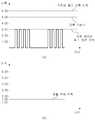
도 5에, 진폭 제어된 펄스 전류가 평활 회로부(70)에 의해 평활 전류로 평활화되는 과정을 나타내는 예시적인 파형도가 개시되어 있다.In FIG. 5, an exemplary waveform diagram showing a process in which the amplitude-controlled pulse current is smoothed into a smoothing current by the smoothing
도 5 (a)에 개시된 바와 같이, 진폭 제어부(60)는 전류 측정부(50)에 의해 측정된 펄스 전류의 진폭이 소정의 진폭 기준치를 초과할 경우 진폭이 낮아진 펄스로 변경되도록 펄스 전류의 진폭을 제어한다. 이후 도 5 (b)에 개시된 바와 같이, 진폭이 작아진 펄스 전류는 평활 회로부(70)를 통해 진폭 제어된 펄스의 크기보다 작은 전압값을 갖는 신호로 변경된다. 이렇게 변경된 신호는 비교/제어기(80)에서 기준값과 비교된다.As disclosed in Fig. 5 (a), the
통상 회로에 문제가 발생할 경우 전기적인 단락에 의해 연속파(CW)가 발생한다. 이러한 점을 감안하여 제품설계 시 단락(short) 테스트를 진행하여 사전에 단락 여부를 판단할 수 있는 기준값을 설정하며, 비교/제어기(80)에 설정된 상기 기준값은 이후 평활 회로부(70)에서 제공하는 신호와 비교하여 회로의 단락 여부 등을 판단한다.Normally, when a problem occurs in a circuit, a continuous wave (CW) is generated by an electrical short. In view of this, a short test is conducted during product design to set a reference value for determining whether a short circuit is present, and the reference value set in the comparator/
비교/제어기(80)는, 평활 회로부(70)에 의해 평활화된 평활 전류가 설정된 과전류 임계치를 초과하는 경우, 전원 공급부(20)에 의해 공급되는 전원이 차단되도록 제어하는 기능을 수행한다. 구체적인 예로, 비교/제어기(80)는, 평활 전류가 과전류 임계치를 초과하는 경우, 전원 공급부(20) 자체에서 전원이 출력되지 않도록 제어할 수 있다.The comparator/
장치 제어기(100)는, 비교/제어기(80)로부터 평활 전류와 과전류 임계치의 비교 정보를 포함하는 상태 정보를 실시간 수신하여 모니터링하고, 데이터베이스화 하는 기능을 수행한다.The
예를 들어, 장치 제어기(100)는, 상태 정보가 모니터 등을 포함하는 상태정보 표시부(110)를 통해 관리자 등에게 실시간 제공되도록 제어할 수 있다.For example, the
예를 들어, 장치 제어기(100)는, 미리 지정된 관리자 단말(200)로부터의 요청에 응답하여, 상태 정보가 관리자 단말(200)로 제공되도록 제어할 수 있다.For example, the
예를 들어, 장치 제어기(100)는, 비교/제어기(80)로부터 전송받은 상태 정보가, 평활 전류가 과전류 임계치를 초과함을 지시하는 경우, 즉, 사용에게 피해를 줄 수도 있는 상황인 경우에는, 상태 정보와 함께 긴급 상황을 알리는 경고 정보를 지정된 관리자 단말(200)로 푸쉬(push)하도록 구성될 수 있다.For example, when the
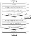
도 3을 추가로 참조하여, 발명의 일 실시 예에 따른 피사체 눈 보호 기능이 구비된 광원을 이용한 카메라(1)의 구체적인 동작을 예시적으로 설명한다. 도 3은 하나의 예시적인 동작일 뿐이며, 본 발명의 일 실시 예가 이에 한정되지는 않는다.With additional reference to FIG. 3, a specific operation of the camera 1 using a light source having a subject eye protection function according to an embodiment of the present invention will be exemplarily described. 3 is only an exemplary operation, and an exemplary embodiment of the present invention is not limited thereto.
도 3을 참조하면, 단계 S10에서는, 제품 동작 초기에 전원 공급부(20)가 전원을 광원 드라이버(30)로 공급하는 과정이 수행된다.Referring to FIG. 3, in step S10, a process of supplying power from the
단계 S20에서는, 광원 드라이버(30)가 광원 드라이버 제어부(40)의 제어에 따라 전원 공급부(20)에 의해 공급되는 전원을 펄스 전류로 변환하여 광원(10)으로 공급하는 과정이 수행되며, 광원(10)의 출력광의 세기는 입력되는 펄스 전류의 세기, 예를 들어, 진폭에 비례한다.In step S20, a process in which the
단계 S30에서는, 전류 측정부(50)가 광원 드라이버(30)로부터 광원(10)으로 공급되는 펄스 전류를 측정하여 진폭 제어부(60)로 전달하는 과정이 수행된다.In step S30, a process of measuring the pulse current supplied from the
단계 S40에서는, 진폭 제어부(60)가 전류 측정부(50)에 의해 측정된 펄스 전류의 진폭을 설정된 진폭 기준치와 비교하는 과정이 수행된다. 단계 S40에서의 비교 결과, 1) 펄스 전류의 진폭이 진폭 기준치를 초과하는 경우, 단계 S50으로 전환되고, 2) 펄스 전류의 진폭이 진폭 기준치 이하인 경우, 단계 S60으로 전환된다.In step S40, a process in which the
단계 S50에서는, 진폭 제어부(60)가 전류 측정부(50)를 통해 전달받은 광원 드라이버(30)의 출력인 펄스 전류의 진폭을 진폭 기준치 이하로 변환하여 평활 회로부(70)로 전달하는 과정이 수행된다. 진폭 제어부(60)에 의해 수행되는 펄스 전류에 대한 진폭 제어는 앞서 도 4를 참조하여 설명하였다.In step S50, the
단계 S60에서는, 펄스 전류의 진폭이 진폭 기준치 이하여서 비교/제어부의 비교 및 제어 동작에 무리가 없는 상태로서, 별도로 진폭을 줄이는 과정이 필요없기 때문에, 진폭 제어부(60)가 펄스 전류를 평활 회로부(70)로 그대로 바이패스(bypass)시키는 과정이 수행된다.In step S60, since the amplitude of the pulse current is equal to or less than the amplitude reference value, the comparison and control operation of the comparison/control unit is not unreasonable, and there is no need to separately reduce the amplitude, the
단계 S70에서는, 평활 회로부(70)가 진폭 제어부(60)에 의해 진폭 제어된 펄스 전류를 평활화(smoothing)하는 과정이 수행된다. 평활 회로부(70)에 의해 펄스 전류가 평활 전류로 평활화되는 과정은 앞서 도 5를 참조하여 설명하였다.In step S70, a process in which the
단계 S80에서는, 비교/제어기(80)가, 평활 회로부(70)에 의해 평활화된 평활 전류와 미리 설정된 과전류 임계치를 비교하는 과정이 수행된다. 단계 S80에서의 비교 결과, 1) 평활 전류가 과전류 임계치를 초과하는 경우, 단계 S90으로 전환되고, 2) 평활 전류가 과전류 임계치 이하인 경우, 별도의 제어 동작없이 단계 S10으로 전환되어 전원이 지속적으로 공급된다.In step S80, the comparison/
단계 S90의 상태는, 평활 전류가 과전류 임계치를 초과하는 상태로서, 이 상태를 방치하면 광원(10)에 지나친 크기의 과전류가 공급되어 광원(10)이 피사체의 눈을 손상시킬 수 있는 고출력광을 발산하게 된다. 따라서, 단계 S90에서는, 비교/제어기(80)가 전원 공급부(20)에 의해 공급되는 전원이 차단되도록 제어하는 과정이 수행된다. 예를 들어, 단계 S90에서, 비교/제어기(80)는, 전원 공급부(20) 자체에서 전원이 출력되지 않도록 제어할 수 있다. 이와 같이 제어하면, 광원 드라이버(30)에 전원이 공급되지 않기 때문에, 광원(10)에도 전류가 입력되지 않아 광원(10)에 의한 광 출력이 차단된다.The state of step S90 is a state in which the smoothing current exceeds the overcurrent threshold. If this state is left unattended, an excessively large overcurrent is supplied to the
도 6은 본 발명의 다른 실시 예에 따른 피사체 눈 보호 기능이 구비된 광원을 이용한 카메라를 나타낸 도면이다. 기본적인 구성 및 기능과 동작은 도 2에 따른 실시 예와 유사하며 이하에서는 차이점을 중심으로 설명한다.6 is a view showing a camera using a light source equipped with a subject eye protection function according to another embodiment of the present invention. The basic configuration, function, and operation are similar to those of the embodiment of FIG. 2, and the differences will be described below.
광원을 이용한 카메라의 경우 다양한 환경에서 피사체의 정보를 센싱하게 된다. 예를 들어 실내가 아닌 실외 환경에 카메라가 노출되어 있을 경우에는 보다 정확한 센싱을 위하여 실내보다 강한 광을 피사체에 조사하여야 하며 또한 보다 멀리 있는 피사체를 센싱하기 위해서도 보다 강한 광을 조사하여야 한다. 반대로 피사체가 가까이에 있을 때는 보다 약한 광을 조사하여야 한다. 이러한 다양한 외부 조건을 판단하기 위하여 본 발명에 따른 카메라는 포토다이오드와 같은 광 센서를 구비하고 광 파장대를 분석하여 카메라가 어떤 조건에 있는지를 능동적으로 판단한다. 만약 광원을 강하게 조사하여야 한다고 판단하면 평활화된 전류의 진폭값이 커질 것이고 이에 따라 안전 기준값인 과전류 임계치도 커지도록 기준값을 가변시킨다. 반대로 광원을 약하게 조사하여야 한다고 판단하면 평활화된 전류의 진폭값을 작게 하고 이에 따라 과전류 임계치도 작아지도록 기준값을 가변시킨다.In the case of a camera using a light source, information of a subject is sensed in various environments. For example, when the camera is exposed to an outdoor environment other than indoors, a stronger light than indoors should be irradiated to the subject for more accurate sensing, and stronger light should be irradiated to sense a farther object. Conversely, when the subject is close, weaker light should be irradiated. In order to determine such various external conditions, the camera according to the present invention includes an optical sensor such as a photodiode and actively determines what conditions the camera is in by analyzing the optical wavelength band. If it is determined that the light source should be strongly irradiated, the amplitude value of the smoothed current will increase, and accordingly, the reference value is varied so that the overcurrent threshold, which is a safety reference value, is also increased. Conversely, if it is determined that the light source should be weakly irradiated, the amplitude value of the smoothed current is reduced and the reference value is changed so that the overcurrent threshold is also reduced accordingly.
도 7은 도 6에 따른 과전류 임계치 기준값이 가변되는 것을 예시적으로 보여주기 위한 파형도이다. 도 7(a)의 경우는 실내에서 카메라가 동작할 경우의 평활 전류 진폭과 그에 따른 과전류 임계치를 보여주는 파형도이며, 도 7(b)의 경우는 실외에서 카메라를 동작시킬 경우에 따른 파형도이다. 실외의 경우 실내보다 강한 강도로 광을 조사해야 하기 때문에 도 7(b)의 평활 전류 진폭이 도 7(a) 보다 크다. 따라서 평활 전류 진폭이 커졌기 때문에 기준값인 과전류 임계치 값도 커지도록 가변시킴으로써 실외 상황에서도 카메라 동작의 오류 없이 보다 정확히 피사체 정보를 센싱할 수 있다. 반대로 실내에 카메라가 설치되어 있다 하더라도 예를 들어 동물 같은 피사체가 갑자기 카메라 쪽으로 다가올 경우에는 도 7(c)와 같이 평활 전류의 진폭을 작게 하고 안전 기준값인 과전류 임계치 값도 작아지도록 설정하여 과도한 광으로부터 피사체를 보호할 수 있도록 한다.7 is a waveform diagram exemplarily showing that the overcurrent threshold reference value according to FIG. 6 is varied. 7(a) is a waveform diagram showing the smoothing current amplitude and the corresponding overcurrent threshold when the camera is operated indoors, and FIG. 7(b) is a waveform diagram when the camera is operated outdoors. . In the case of outdoors, since light must be irradiated with a stronger intensity than indoors, the smoothing current amplitude of FIG. 7(b) is greater than that of FIG. 7(a). Therefore, since the smoothing current amplitude is increased, the overcurrent threshold value, which is the reference value, is also varied to increase, so that even in outdoor conditions, subject information can be more accurately sensed without errors in camera operation. Conversely, even if a camera is installed indoors, for example, when a subject such as an animal suddenly approaches the camera, the amplitude of the smoothing current is reduced as shown in Fig. 7(c), and the overcurrent threshold value, which is a safety reference value, is set to decrease from excessive light. Make it possible to protect the subject.
도 6에 따르면, 광 센서(120)를 통해 측정된 정보를 장치 제어기(100)가 받아 이를 분석하여 비교/제어기(80)의 기준값을 가변적으로 제어한다. 또한 별도의 광 센서(120) 없이 렌즈모듈(6)과 렌즈 구동부(90)를 통해 확보된 피사체 영상정보를 장치 제어기(100)가 분석하여 비교/제어기(80)의 기준값을 가변적으로 제어할 수 있다. 비교/제어기(80)는 가변적으로 제어된 기준값(과전류 임계치)과 평활 회로부(70)로부터 제공되는 평활 전류 진폭값을 비교하여 만약 평활 전류 진폭값이 기준값인 과전류 임계치보다 클 경우 전원 공급부(20)가 더 이상 전원을 공급하지 못하도록 제어한다. 또한 장치 제어기(100)는 전원 공급부(20)가 더 이상 전원을 공급하지 못하는 상황이 되면 렌즈 구동부(90)도 더 이상 동작하지 않도록 제어하여 전력손실 문제를 방지할 수 있다.According to FIG. 6, the
도 6에 따른 실시 예에서는 서미스터(thermistor)와 같은 온도 센서(3)를 더 구비하여 광원을 이용한 카메라에 부가적인 보호 기능을 제공할 수 있다. 보다 구체적으로, 보다 강한 광을 조사할 경우 광원 주변에 많은 열 에너지가 발생할 수 있고 이러한 열 에너지가 지속적으로 축적될 경우 회로소자를 손상시킬 가능성이 있다. 이러한 문제점을 해결하기 위하여 광원 주변에 온도 센서(3)를 배치하고 온도 정보를 장치 제어기(100)가 받아 이를 분석하여 만약 설정시간에 따른 설정온도보다 높아질 경우 장치 제어기(100)가 전원 공급부(20)를 제어하여 전원 공급부(20)가 더 이상 전원을 공급하지 못하도록 제어한다.In the embodiment of FIG. 6, a temperature sensor 3 such as a thermistor may be further provided to provide an additional protection function to a camera using a light source. More specifically, when a stronger light is irradiated, a lot of thermal energy may be generated around the light source, and if such thermal energy is continuously accumulated, there is a possibility of damaging the circuit device. In order to solve this problem, the temperature sensor 3 is disposed around the light source, and the
또한 장치 제어기(100)가 펄스 전류 생성을 위해 광원 드라이버 제어부(40)에 인가한 클락 신호와 전류 측정부(50)에서 측정된 실제 펄스 전류의 파형을 상호 비교하여 만약 두 펄스의 모양이 상이할 경우 이상 펄스 전류가 광원에 공급되고 있다고 판단하여 더 이상 전원 공급부(20)가 전원을 공급하지 못하도록 제어하여 부가적인 보호 기능을 제공할 수 있다.In addition, the
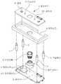
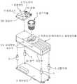
도 8 및 도 9는 본 발명의 일 실시 예에 따른 피사체 눈 보호 기능이 구비된 광원을 이용한 카메라의 예시적인 분해사시도들이다.8 and 9 are exemplary exploded perspective views of a camera using a light source equipped with a subject eye protection function according to an embodiment of the present invention.
도 8 및 도 9를 참조하면, 본 발명의 일 실시 예에 따른 피사체 눈 보호 기능이 구비된 광원을 이용한 카메라(1)는 피사체에 광을 조사하는 광원(10), 피사체에서 반사된 광이 입사되는 렌즈모듈(6), 렌즈모듈(6)이 안착되는 렌즈베이스(7), 광원(10)과 이에 인접하여 온도를 측정하는 온도센서(3) 및 주변 광을 측정하는 광 센서(120)가 안착되는 광원보드(1), 광원보드(1)가 안착되며 광원(10) 등에서 발생된 열을 외부로 발산시키기 위한 히트싱크(4), 카메라의 전체 동작을 제어하기 위한 장치 제어기(100)와 전원 공급부(20), 전류 측정부(50), 평활 회로부(70) 등과 같은 각종 회로소자(9) 등이 안착되는 제어보드(8) 및 제어보드(8)와 히트싱크(4)를 상호 결합시키는 결합부재(5)를 포함하여 구성될 수 있다. 특히 제조공정을 단순화하며 방열 효율 향상 및 제조원가 절감을 위해 도 8에 예시된 히트싱크(4)와 렌즈베이스(7)를 일체형으로 하여 도 9에 예시된 바와 같이 렌즈모듈(6)이 히트싱크/렌즈베이스 일체형 모듈(2)에 안착될 수 있게 구성할 수 있다. 특히 히트싱크/렌즈베이스 일체형 모듈(2)의 일단에는 광원(10)과 광 센서(120) 또는 온도센서(3) 등이 안착되어 있는 광원보드(1)가 안착될 수 있고 타단에는 공기와의 접촉 면적을 넓혀 방열 효율을 극대화하기 위한 복수의 돌기가 형성될 수 있다. 또한 도 8에 개시된 예와는 상이하게 도 9에 예시된 예에 따르면, 장치 제어기(100)와 전원 공급부(20), 전류 측정부(50), 평활 회로부(70) 등과 같은 각종 회로소자(9) 등은 제어보드(8)의 양면 중에서 도면상 도시되지 않은 하면에 안착될 수 있다.8 and 9, a camera 1 using a light source equipped with a subject eye protection function according to an embodiment of the present invention includes a
이상에서 상세히 설명한 바와 같이 본 발명에 따르면, ToF(Time of Flight) 카메라 등과 같은 광원을 이용한 카메라의 동작 중에 광원으로 과전류가 유입되어 피사체인 사람 등의 눈이 손상되는 위험을 방지할 수 있는 피사체 눈 보호 기능이 구비된 광원을 이용한 카메라가 제공되는 효과가 있다. 또한 과전류를 차단하기 위한 기준값이 가변되도록 하여 보다 정확한 피사체 정보를 센싱할 수 있으며 부가적인 안전성도 향상시킬 수 있다.As described in detail above, according to the present invention, an overcurrent is introduced into the light source during operation of a camera using a light source such as a Time of Flight (ToF) camera, which can prevent the risk of damage to the eyes of a person, etc. There is an effect that a camera using a light source equipped with a protection function is provided. In addition, more accurate subject information can be sensed by changing a reference value for blocking overcurrent, and additional safety can be improved.
1: 피사체 눈 보호 기능이 구비된 광원을 이용한 카메라
2: 히트싱크/렌즈베이스 일체형 모듈, 3: 온도센서, 4: 히트싱크
5: 결합부재, 6: 렌즈모듈, 7: 렌즈베이스, 8: 제어보드
9: 회로소자, 10: 광원, 20: 전원 공급부, 30: 광원 드라이버
40: 광원 드라이버 제어부, 50: 전류 측정부, 60: 진폭 제어부
70: 평활 회로부, 80: 비교/제어기, 90: 렌즈 구동부
100: 장치 제어기, 110: 상태정보 표시부, 120: 광 센서
200: 관리자 단말1: Camera using a light source equipped with a subject eye protection function
2: heat sink/lens base integrated module, 3: temperature sensor, 4: heat sink
5: coupling member, 6: lens module, 7: lens base, 8: control board
9: circuit element, 10: light source, 20: power supply, 30: light source driver
40: light source driver control unit, 50: current measurement unit, 60: amplitude control unit
70: smoothing circuit unit, 80: comparator/controller, 90: lens driving unit
100: device controller, 110: status information display, 120: optical sensor
200: manager terminal
Claims (13)
Translated fromKorean상기 광원으로 공급되는 펄스 전류를 측정하는 전류 측정부;
상기 전류 측정부에 의해 측정된 펄스 전류의 진폭을 제어하는 진폭 제어부;
상기 진폭 제어부에 의해 진폭 제어된 펄스 전류를 평활화(smoothing)하는 평활 회로부;
상기 평활 회로부에 의해 평활화된 평활 전류가 설정된 임계치를 초과하는 경우 상기 전원 공급부에 의해 공급되는 전원이 차단되도록 제어하는 비교/제어기; 및
상기 비교/제어기로부터 상기 평활 전류와 상기 임계치의 비교 정보를 포함하는 상태 정보를 실시간 수신하여 모니터링하는 장치 제어기를 포함하고,
상기 장치 제어기는 상기 광원과 전기적으로 연결되어 있으며, 상기 광원은 광원보드에 안착되며, 상기 광원보드는 히트싱크에 안착되며, 상기 히트싱크는 결합부재를 통해 상기 장치 제어기가 안착되어 있는 제어보드에 체결되는, 카메라.A light source driver installed between a light source for irradiating light onto a subject and a power supply unit to convert power supplied by the power supply unit into a pulse current and supply it to the light source;
A current measuring unit that measures a pulse current supplied to the light source;
An amplitude control unit controlling an amplitude of the pulse current measured by the current measuring unit;
A smoothing circuit unit for smoothing the pulse current amplitude controlled by the amplitude control unit;
A comparator/controller for controlling the power supplied by the power supply to be cut off when the smoothing current smoothed by the smoothing circuit unit exceeds a set threshold; And
A device controller for receiving and monitoring status information including comparison information between the smoothing current and the threshold value from the comparator/controller in real time,
The device controller is electrically connected to the light source, the light source is mounted on a light source board, the light source board is mounted on a heat sink, and the heat sink is connected to a control board on which the device controller is mounted through a coupling member. Fastened, camera.
상기 진폭 제어부는,
상기 전류 측정부에 의해 측정된 펄스 전류의 진폭을 설정된 진폭 기준치와 비교하고, 상기 펄스 전류의 진폭이 상기 진폭 기준치를 초과하는 경우, 상기 펄스 전류의 진폭을 상기 진폭 기준치 이하로 변환하는 것을 특징으로 하는, 카메라.The method of claim 1,
The amplitude control unit,
The amplitude of the pulse current measured by the current measuring unit is compared with a set amplitude reference value, and when the amplitude of the pulse current exceeds the amplitude reference value, the amplitude of the pulse current is converted to be equal to or less than the amplitude reference value. To do, the camera.
상기 장치 제어기는 상기 상태 정보를 상태정보 표시부 또는 관리자 단말을 통해 관리자에게 제공되도록 제어하는 것을 특징으로 하는, 카메라.The method of claim 1,
The device controller controls the status information to be provided to the manager through a status information display unit or a manager terminal.
상기 장치 제어기는 상기 평활 전류가 상기 임계치를 초과하는 상태의 상태 정보를 수신할 경우, 상기 상태 정보와 함께 긴급 상황을 알리는 경고 정보를 지정된 관리자 단말로 푸쉬(push)하는 것을 특징으로 하는, 카메라.The method of claim 1,
The device controller, when receiving status information in a state in which the smoothing current exceeds the threshold value, pushes warning information indicating an emergency situation along with the status information to a designated manager terminal.
상기 임계치는 가변될 수 있는 것을 특징으로 하는, 카메라.The method of claim 1,
Camera, characterized in that the threshold can be varied.
상기 평활 전류의 진폭이 커지는 상황에서는 상기 임계치가 커지도록 가변되고, 상기 평활 전류의 진폭이 작아지는 상황에서는 상기 임계치가 작아지도록 가변되는 것을 특징으로 하는, 카메라.The method of claim 6,
The camera according to claim 1, wherein the threshold value is varied so that the threshold value increases when the amplitude of the smoothing current increases, and the threshold value is changed to decrease when the amplitude of the smoothing current decreases.
상기 광원보드는 광 센서 또는 온도 센서 중 적어도 하나를 더 구비하는 것을 특징으로 하는, 카메라.The method of claim 1,
The light source board further comprises at least one of an optical sensor and a temperature sensor.
상기 히트싱크는 피사체로부터 반사된 광이 입사되는 렌즈모듈이 안착될 수 있는 렌즈베이스 역할도 하는 것을 특징으로 하는, 카메라.The method of claim 1,
The heat sink is characterized in that it also serves as a lens base on which the lens module to which the light reflected from the subject is incident is mounted.
상기 렌즈베이스 역할도 하는 히트싱크의 일측에는 상기 광원보드가 안착되며 타측에는 복수의 돌기가 형성되어 있는 것을 특징으로 하는, 카메라.The method of claim 10,
The camera, characterized in that the light source board is mounted on one side of the heat sink, which also serves as the lens base, and a plurality of protrusions are formed on the other side.
상기 장치 제어기는 상기 온도 센서로부터 온도에 관한 정보를 받아 상기 전원 공급부를 제어하는 것을 특징으로 하는, 카메라.The method of claim 9,
The device controller is characterized in that to control the power supply by receiving information about the temperature from the temperature sensor.
상기 장치 제어기는 상기 광원 드라이버를 구동하기 위한 클락신호와 상기 전류 측정부를 통해 측정된 펄스 전류를 비교하여 상기 전원 공급부를 제어하는 것을 특징으로 하는, 카메라.
The method of claim 1,
Wherein the device controller controls the power supply unit by comparing a clock signal for driving the light source driver with a pulse current measured through the current measuring unit.
Priority Applications (4)
| Application Number | Priority Date | Filing Date | Title |
|---|---|---|---|
| CN201910304502.6ACN110389357B (en) | 2018-04-19 | 2019-04-16 | Camera using light source with object eye protection function |
| JP2019078394AJP2019191173A (en) | 2018-04-19 | 2019-04-17 | camera |
| US16/386,769US10481470B2 (en) | 2018-04-19 | 2019-04-17 | Camera using light source having subject eye protection function |
| EP19169898.4AEP3557951A1 (en) | 2018-04-19 | 2019-04-17 | Camera using light source having subject eye protection function |
Applications Claiming Priority (2)
| Application Number | Priority Date | Filing Date | Title |
|---|---|---|---|
| KR1020180047105 | 2018-04-24 | ||
| KR20180047105 | 2018-04-24 |
Publications (2)
| Publication Number | Publication Date |
|---|---|
| KR20190123669A KR20190123669A (en) | 2019-11-01 |
| KR102161132B1true KR102161132B1 (en) | 2020-09-29 |
Family
ID=68535713
Family Applications (1)
| Application Number | Title | Priority Date | Filing Date |
|---|---|---|---|
| KR1020190018596AActiveKR102161132B1 (en) | 2018-04-19 | 2019-02-18 | A camera using light source having subject eye protect function |
Country Status (1)
| Country | Link |
|---|---|
| KR (1) | KR102161132B1 (en) |
Families Citing this family (2)
| Publication number | Priority date | Publication date | Assignee | Title |
|---|---|---|---|---|
| WO2021145473A1 (en)* | 2020-01-14 | 2021-07-22 | 엘지전자 주식회사 | Mobile terminal and control method therefor |
| KR102827452B1 (en)* | 2020-03-16 | 2025-07-01 | 엘지이노텍 주식회사 | Camera module |
Citations (2)
| Publication number | Priority date | Publication date | Assignee | Title |
|---|---|---|---|---|
| JP2003208995A (en)* | 2001-09-10 | 2003-07-25 | Matsushita Electric Ind Co Ltd | Bulb-type fluorescent lamp |
| JP2009056248A (en)* | 2007-09-03 | 2009-03-19 | Fujifilm Corp | Light source device, drive control method for light source device, and endoscope |
Family Cites Families (5)
| Publication number | Priority date | Publication date | Assignee | Title |
|---|---|---|---|---|
| JP3387573B2 (en)* | 1993-09-28 | 2003-03-17 | 株式会社日立製作所 | Imaging device |
| KR101770872B1 (en) | 2013-12-27 | 2017-08-23 | 주식회사 만도 | TOF camera for vehicle and method for driving thereof |
| KR102306539B1 (en) | 2015-03-12 | 2021-09-29 | 삼성전자주식회사 | Method and device for irradiating light used to capture iris |
| KR20170051651A (en)* | 2015-10-30 | 2017-05-12 | 삼성전자주식회사 | Lighting system, lighting control device and method |
| CN105455946B (en) | 2015-11-24 | 2017-05-03 | 京东方科技集团股份有限公司 | Protection device, protection method, wearable equipment and display device |
- 2019
- 2019-02-18KRKR1020190018596Apatent/KR102161132B1/enactiveActive
Patent Citations (2)
| Publication number | Priority date | Publication date | Assignee | Title |
|---|---|---|---|---|
| JP2003208995A (en)* | 2001-09-10 | 2003-07-25 | Matsushita Electric Ind Co Ltd | Bulb-type fluorescent lamp |
| JP2009056248A (en)* | 2007-09-03 | 2009-03-19 | Fujifilm Corp | Light source device, drive control method for light source device, and endoscope |
Also Published As
| Publication number | Publication date |
|---|---|
| KR20190123669A (en) | 2019-11-01 |
Similar Documents
| Publication | Publication Date | Title |
|---|---|---|
| JP7291412B2 (en) | Transmitter assembly for free space power transmission and data communication systems | |
| US20220311521A1 (en) | System for optical wireless power supply | |
| KR102161132B1 (en) | A camera using light source having subject eye protect function | |
| US20190341813A1 (en) | System for optical wireless power supply | |
| CN110389357B (en) | Camera using light source with object eye protection function | |
| US6801557B2 (en) | Laser driver for a laser sensing system | |
| CN107894243A (en) | For carrying out the photoelectric sensor and method of optical detection to monitored area | |
| US4884275A (en) | Laser safety shutoff system | |
| US9184557B2 (en) | Optical module and method of controlling optical module | |
| KR102152248B1 (en) | Infrared temperature measurement system and method using laser pointer | |
| US8368318B2 (en) | Pocket tool with a light pointer | |
| CN105938974B (en) | A kind of laser variable pulse width protection system | |
| US20220291344A1 (en) | Protection cover and light emitting device | |
| CN108318141B (en) | Temperature control method of heating element, night vision system calibration equipment and system | |
| Życzkowski et al. | Research and parameter optimization of the infrared sensor for eye track | |
| KR20210043763A (en) | Beam projector module providing eye protection | |
| US7505691B2 (en) | Optical emission module | |
| KR102087519B1 (en) | Beam projector module for preventing malfunction of eye-safety function, and control method thereof | |
| KR20200004757A (en) | Beam projector module for performing eye-safety function using temperature, and control method thereof | |
| US12062885B2 (en) | Light module and a method for its operation | |
| US9325153B2 (en) | Method to control transmitter optical module | |
| CN105244745A (en) | Safe power control device of laser device for ophthalmic medical treatment OCT technique | |
| EP3732508B1 (en) | Optoelectronic modules and methods for operating the same | |
| US20160301190A1 (en) | Laser device | |
| CN104752955B (en) | A kind of high-power semiconductor laser light source for processing system of feedback against sunshine |
Legal Events
| Date | Code | Title | Description |
|---|---|---|---|
| A201 | Request for examination | ||
| PA0109 | Patent application | Patent event code:PA01091R01D Comment text:Patent Application Patent event date:20190218 | |
| PA0201 | Request for examination | ||
| PG1501 | Laying open of application | ||
| E902 | Notification of reason for refusal | ||
| PE0902 | Notice of grounds for rejection | Comment text:Notification of reason for refusal Patent event date:20200217 Patent event code:PE09021S01D | |
| E701 | Decision to grant or registration of patent right | ||
| PE0701 | Decision of registration | Patent event code:PE07011S01D Comment text:Decision to Grant Registration Patent event date:20200626 | |
| GRNT | Written decision to grant | ||
| PR0701 | Registration of establishment | Comment text:Registration of Establishment Patent event date:20200923 Patent event code:PR07011E01D | |
| PR1002 | Payment of registration fee | Payment date:20200924 End annual number:3 Start annual number:1 | |
| PG1601 | Publication of registration | ||
| PR1001 | Payment of annual fee | Payment date:20230314 Start annual number:4 End annual number:6 |