KR102160734B1 - Image taking system using wireless rechargeable drones - Google Patents
Image taking system using wireless rechargeable dronesDownload PDFInfo
- Publication number
- KR102160734B1 KR102160734B1KR1020180112251AKR20180112251AKR102160734B1KR 102160734 B1KR102160734 B1KR 102160734B1KR 1020180112251 AKR1020180112251 AKR 1020180112251AKR 20180112251 AKR20180112251 AKR 20180112251AKR 102160734 B1KR102160734 B1KR 102160734B1
- Authority
- KR
- South Korea
- Prior art keywords
- drone
- photographing
- charging
- shooting
- drones
- Prior art date
- Legal status (The legal status is an assumption and is not a legal conclusion. Google has not performed a legal analysis and makes no representation as to the accuracy of the status listed.)
- Active
Links
Images


Classifications
- B—PERFORMING OPERATIONS; TRANSPORTING
- B64—AIRCRAFT; AVIATION; COSMONAUTICS
- B64U—UNMANNED AERIAL VEHICLES [UAV]; EQUIPMENT THEREFOR
- B64U50/00—Propulsion; Power supply
- B64U50/30—Supply or distribution of electrical power
- B64U50/37—Charging when not in flight
- B64U50/38—Charging when not in flight by wireless transmission
- B—PERFORMING OPERATIONS; TRANSPORTING
- B60—VEHICLES IN GENERAL
- B60L—PROPULSION OF ELECTRICALLY-PROPELLED VEHICLES; SUPPLYING ELECTRIC POWER FOR AUXILIARY EQUIPMENT OF ELECTRICALLY-PROPELLED VEHICLES; ELECTRODYNAMIC BRAKE SYSTEMS FOR VEHICLES IN GENERAL; MAGNETIC SUSPENSION OR LEVITATION FOR VEHICLES; MONITORING OPERATING VARIABLES OF ELECTRICALLY-PROPELLED VEHICLES; ELECTRIC SAFETY DEVICES FOR ELECTRICALLY-PROPELLED VEHICLES
- B60L53/00—Methods of charging batteries, specially adapted for electric vehicles; Charging stations or on-board charging equipment therefor; Exchange of energy storage elements in electric vehicles
- B60L53/30—Constructional details of charging stations
- B60L53/35—Means for automatic or assisted adjustment of the relative position of charging devices and vehicles
- B60L53/37—Means for automatic or assisted adjustment of the relative position of charging devices and vehicles using optical position determination, e.g. using cameras
- B—PERFORMING OPERATIONS; TRANSPORTING
- B60—VEHICLES IN GENERAL
- B60L—PROPULSION OF ELECTRICALLY-PROPELLED VEHICLES; SUPPLYING ELECTRIC POWER FOR AUXILIARY EQUIPMENT OF ELECTRICALLY-PROPELLED VEHICLES; ELECTRODYNAMIC BRAKE SYSTEMS FOR VEHICLES IN GENERAL; MAGNETIC SUSPENSION OR LEVITATION FOR VEHICLES; MONITORING OPERATING VARIABLES OF ELECTRICALLY-PROPELLED VEHICLES; ELECTRIC SAFETY DEVICES FOR ELECTRICALLY-PROPELLED VEHICLES
- B60L53/00—Methods of charging batteries, specially adapted for electric vehicles; Charging stations or on-board charging equipment therefor; Exchange of energy storage elements in electric vehicles
- B60L53/30—Constructional details of charging stations
- B60L53/35—Means for automatic or assisted adjustment of the relative position of charging devices and vehicles
- B60L53/38—Means for automatic or assisted adjustment of the relative position of charging devices and vehicles specially adapted for charging by inductive energy transfer
- B—PERFORMING OPERATIONS; TRANSPORTING
- B60—VEHICLES IN GENERAL
- B60L—PROPULSION OF ELECTRICALLY-PROPELLED VEHICLES; SUPPLYING ELECTRIC POWER FOR AUXILIARY EQUIPMENT OF ELECTRICALLY-PROPELLED VEHICLES; ELECTRODYNAMIC BRAKE SYSTEMS FOR VEHICLES IN GENERAL; MAGNETIC SUSPENSION OR LEVITATION FOR VEHICLES; MONITORING OPERATING VARIABLES OF ELECTRICALLY-PROPELLED VEHICLES; ELECTRIC SAFETY DEVICES FOR ELECTRICALLY-PROPELLED VEHICLES
- B60L58/00—Methods or circuit arrangements for monitoring or controlling batteries or fuel cells, specially adapted for electric vehicles
- B60L58/10—Methods or circuit arrangements for monitoring or controlling batteries or fuel cells, specially adapted for electric vehicles for monitoring or controlling batteries
- B60L58/12—Methods or circuit arrangements for monitoring or controlling batteries or fuel cells, specially adapted for electric vehicles for monitoring or controlling batteries responding to state of charge [SoC]
- B—PERFORMING OPERATIONS; TRANSPORTING
- B64—AIRCRAFT; AVIATION; COSMONAUTICS
- B64C—AEROPLANES; HELICOPTERS
- B64C39/00—Aircraft not otherwise provided for
- B64C39/02—Aircraft not otherwise provided for characterised by special use
- B64C39/024—Aircraft not otherwise provided for characterised by special use of the remote controlled vehicle type, i.e. RPV
- B—PERFORMING OPERATIONS; TRANSPORTING
- B64—AIRCRAFT; AVIATION; COSMONAUTICS
- B64U—UNMANNED AERIAL VEHICLES [UAV]; EQUIPMENT THEREFOR
- B64U50/00—Propulsion; Power supply
- B64U50/10—Propulsion
- B64U50/19—Propulsion using electrically powered motors
- B—PERFORMING OPERATIONS; TRANSPORTING
- B64—AIRCRAFT; AVIATION; COSMONAUTICS
- B64U—UNMANNED AERIAL VEHICLES [UAV]; EQUIPMENT THEREFOR
- B64U70/00—Launching, take-off or landing arrangements
- B64U70/90—Launching from or landing on platforms
- G—PHYSICS
- G03—PHOTOGRAPHY; CINEMATOGRAPHY; ANALOGOUS TECHNIQUES USING WAVES OTHER THAN OPTICAL WAVES; ELECTROGRAPHY; HOLOGRAPHY
- G03B—APPARATUS OR ARRANGEMENTS FOR TAKING PHOTOGRAPHS OR FOR PROJECTING OR VIEWING THEM; APPARATUS OR ARRANGEMENTS EMPLOYING ANALOGOUS TECHNIQUES USING WAVES OTHER THAN OPTICAL WAVES; ACCESSORIES THEREFOR
- G03B15/00—Special procedures for taking photographs; Apparatus therefor
- G03B15/006—Apparatus mounted on flying objects
- H—ELECTRICITY
- H04—ELECTRIC COMMUNICATION TECHNIQUE
- H04N—PICTORIAL COMMUNICATION, e.g. TELEVISION
- H04N7/00—Television systems
- H04N7/18—Closed-circuit television [CCTV] systems, i.e. systems in which the video signal is not broadcast
- H04N7/181—Closed-circuit television [CCTV] systems, i.e. systems in which the video signal is not broadcast for receiving images from a plurality of remote sources
- B—PERFORMING OPERATIONS; TRANSPORTING
- B60—VEHICLES IN GENERAL
- B60L—PROPULSION OF ELECTRICALLY-PROPELLED VEHICLES; SUPPLYING ELECTRIC POWER FOR AUXILIARY EQUIPMENT OF ELECTRICALLY-PROPELLED VEHICLES; ELECTRODYNAMIC BRAKE SYSTEMS FOR VEHICLES IN GENERAL; MAGNETIC SUSPENSION OR LEVITATION FOR VEHICLES; MONITORING OPERATING VARIABLES OF ELECTRICALLY-PROPELLED VEHICLES; ELECTRIC SAFETY DEVICES FOR ELECTRICALLY-PROPELLED VEHICLES
- B60L2200/00—Type of vehicles
- B60L2200/10—Air crafts
- B—PERFORMING OPERATIONS; TRANSPORTING
- B60—VEHICLES IN GENERAL
- B60Y—INDEXING SCHEME RELATING TO ASPECTS CROSS-CUTTING VEHICLE TECHNOLOGY
- B60Y2200/00—Type of vehicle
- B60Y2200/50—Aeroplanes, Helicopters
- B60Y2200/51—Aeroplanes
- B64C2201/042—
- B64C2201/066—
- B64C2201/127—
- B—PERFORMING OPERATIONS; TRANSPORTING
- B64—AIRCRAFT; AVIATION; COSMONAUTICS
- B64U—UNMANNED AERIAL VEHICLES [UAV]; EQUIPMENT THEREFOR
- B64U2101/00—UAVs specially adapted for particular uses or applications
- B64U2101/30—UAVs specially adapted for particular uses or applications for imaging, photography or videography
- Y—GENERAL TAGGING OF NEW TECHNOLOGICAL DEVELOPMENTS; GENERAL TAGGING OF CROSS-SECTIONAL TECHNOLOGIES SPANNING OVER SEVERAL SECTIONS OF THE IPC; TECHNICAL SUBJECTS COVERED BY FORMER USPC CROSS-REFERENCE ART COLLECTIONS [XRACs] AND DIGESTS
- Y02—TECHNOLOGIES OR APPLICATIONS FOR MITIGATION OR ADAPTATION AGAINST CLIMATE CHANGE
- Y02T—CLIMATE CHANGE MITIGATION TECHNOLOGIES RELATED TO TRANSPORTATION
- Y02T10/00—Road transport of goods or passengers
- Y02T10/60—Other road transportation technologies with climate change mitigation effect
- Y02T10/70—Energy storage systems for electromobility, e.g. batteries
- Y—GENERAL TAGGING OF NEW TECHNOLOGICAL DEVELOPMENTS; GENERAL TAGGING OF CROSS-SECTIONAL TECHNOLOGIES SPANNING OVER SEVERAL SECTIONS OF THE IPC; TECHNICAL SUBJECTS COVERED BY FORMER USPC CROSS-REFERENCE ART COLLECTIONS [XRACs] AND DIGESTS
- Y02—TECHNOLOGIES OR APPLICATIONS FOR MITIGATION OR ADAPTATION AGAINST CLIMATE CHANGE
- Y02T—CLIMATE CHANGE MITIGATION TECHNOLOGIES RELATED TO TRANSPORTATION
- Y02T10/00—Road transport of goods or passengers
- Y02T10/60—Other road transportation technologies with climate change mitigation effect
- Y02T10/7072—Electromobility specific charging systems or methods for batteries, ultracapacitors, supercapacitors or double-layer capacitors
- Y—GENERAL TAGGING OF NEW TECHNOLOGICAL DEVELOPMENTS; GENERAL TAGGING OF CROSS-SECTIONAL TECHNOLOGIES SPANNING OVER SEVERAL SECTIONS OF THE IPC; TECHNICAL SUBJECTS COVERED BY FORMER USPC CROSS-REFERENCE ART COLLECTIONS [XRACs] AND DIGESTS
- Y02—TECHNOLOGIES OR APPLICATIONS FOR MITIGATION OR ADAPTATION AGAINST CLIMATE CHANGE
- Y02T—CLIMATE CHANGE MITIGATION TECHNOLOGIES RELATED TO TRANSPORTATION
- Y02T50/00—Aeronautics or air transport
- Y02T50/50—On board measures aiming to increase energy efficiency
- Y—GENERAL TAGGING OF NEW TECHNOLOGICAL DEVELOPMENTS; GENERAL TAGGING OF CROSS-SECTIONAL TECHNOLOGIES SPANNING OVER SEVERAL SECTIONS OF THE IPC; TECHNICAL SUBJECTS COVERED BY FORMER USPC CROSS-REFERENCE ART COLLECTIONS [XRACs] AND DIGESTS
- Y02—TECHNOLOGIES OR APPLICATIONS FOR MITIGATION OR ADAPTATION AGAINST CLIMATE CHANGE
- Y02T—CLIMATE CHANGE MITIGATION TECHNOLOGIES RELATED TO TRANSPORTATION
- Y02T90/00—Enabling technologies or technologies with a potential or indirect contribution to GHG emissions mitigation
- Y02T90/10—Technologies relating to charging of electric vehicles
- Y02T90/12—Electric charging stations
Landscapes
- Engineering & Computer Science (AREA)
- Power Engineering (AREA)
- Transportation (AREA)
- Mechanical Engineering (AREA)
- Aviation & Aerospace Engineering (AREA)
- Combustion & Propulsion (AREA)
- Chemical & Material Sciences (AREA)
- Multimedia (AREA)
- Signal Processing (AREA)
- Physics & Mathematics (AREA)
- General Physics & Mathematics (AREA)
- Life Sciences & Earth Sciences (AREA)
- Sustainable Development (AREA)
- Sustainable Energy (AREA)
- Computer Networks & Wireless Communication (AREA)
- Closed-Circuit Television Systems (AREA)
- Control Of Position, Course, Altitude, Or Attitude Of Moving Bodies (AREA)
Abstract
Translated fromKorean
Description
Translated fromKorean본 발명은 무선 충전 드론을 이용한 촬영 시스템에 관한 것으로서, 구체적으로는 다수의 드론을 이용하여 모니터링 지역을 지속적으로 촬영 가능한 무선 충전 드론을 이용한 촬영 시스템에 관한 것이다.The present invention relates to a photographing system using a wireless charging drone, and more particularly, to a photographing system using a wireless charging drone capable of continuously photographing a monitoring area using a plurality of drones.
무인 항공기(Unmanned aerial vehicle)가 널리 활용되고 있다. 무인 항공기는 무인 항공기의 소리나 소음 특성으로 인해 일반적으로 드론(drone)으로 지칭된다. 이하에서는 무인 항공기를 '드론'이라 지칭한다. 드론은 고정익 드론, 프로펠러형 드론 등이 있다.Unmanned aerial vehicles are widely used. Unmanned aerial vehicles are generally referred to as drones due to the sound or noise characteristics of unmanned aerial vehicles. Hereinafter, the unmanned aerial vehicle is referred to as a'drone'. Drones include fixed-wing drones and propeller-type drones.
드론은 다양한 분야에서 활용되며, 카메라 등을 장착하고 실종자 수색, 산불감시, 차량추적, 각종 설비의 점검, 항공사진 촬영 등에 활용되고 심지어 드론을 활용한 택배도 가능하게 되었다.Drones are used in various fields, equipped with cameras, etc., are used for search for missing persons, forest fire monitoring, vehicle tracking, inspection of various facilities, aerial photography, and even delivery using drones.
드론은 넓은 지역을 촬영할 수 있으며, 예를 들어, 드론은 넓은 지역 내를 이동하면서 특정 대상(자)을 감시하거나 임의의 지역 이미지를 촬영할 수 있다. 그 촬영에 따라 구성되는 이미지들은 해당 지역의 3D 맵핑 구성에도 이용 가능하다.A drone can shoot a large area, for example, a drone can monitor a specific target (party) while moving within a large area or take an image of an arbitrary area. The images formed according to the shooting can also be used for the 3D mapping configuration of the area.
무선 통신을 통해 원격에서 제어할 수 있어, 드론은 다양한 장점을 제공할 수 있다. 예를 들어, 드론을 통해 위험한 곳, 접근 어려운 곳 등의 촬영이나 감시가 가능하다.Since it can be controlled remotely via wireless communication, drones can provide a variety of advantages. For example, it is possible to shoot or monitor dangerous places and places that are difficult to access through drones.
이러한 뚜렷한 장점이 존재하는 한편, 드론은 구비된 배터리 용량의 한계로 인해서 비행 시간의 제약이 있다. 일반적으로 알려졌거나 상용화된 드론들은 대략 20분 내외의 비행시간을 가지고 비행 이후에는 다시 충전을 해야만 재비행이 가능하다.While these distinct advantages exist, the drone has a limitation in flight time due to the limitation of the installed battery capacity. Generally known or commercialized drones have a flight time of about 20 minutes and can be re-flighted only by recharging after flight.
짧은 비행시간은 드론 촬영 시스템에 있어 중대한 문제점을 야기한다. 예를 들어, 넓은 지역을 감시하기 위해서는 드론이 계속 비행하여 해당 지역을 지속적으로 촬영할 필요가 존재하나 드론의 비행시간 제약으로 연속적인 감시가 어렵다. 또한 항공 촬영에서는 정해진 지역 전체를 촬영하기 위해 1대의 비행시간으로는 부족하고 복귀 후 촬영된 영상을 다운로드 한 후 다시 가서 촬영해야 하는 등 번거로운 점이 많고 전체 촬영시간이 많이 소요되는 문제점이 있다.The short flight time poses a significant problem for drone photography systems. For example, in order to monitor a large area, it is necessary for the drone to continuously fly and shoot the area, but it is difficult to continuously monitor due to the flight time constraints of the drone. In addition, in aerial photography, it is not enough to take one flight time to shoot the entire designated area, and there is a problem that there are many inconveniences such as having to download the captured image after returning and then go back to shoot, and take a lot of total shooting time.
또한, 넓은 지역의 3D 맵핑을 위해서는 지상의 기준점이 되는 위치에 대공표지판이 항공 촬영 전에 미리 설치되어야 한다. 대공표지판은 항공 촬영후에 컴퓨터 모니터에서 특정 형상을 가지고 인식 가능하다.In addition, for 3D mapping of a large area, an anti-aircraft sign must be installed in advance at a location that becomes a reference point on the ground before aerial photography. The anti-aircraft sign can be recognized with a specific shape on a computer monitor after aerial photography.
본 출원 발명자 등의 선출원인 특허발명(등록특허 10-1885184호, 2018년08월06일 공고)에서 개시한 바와 같이 대공표지판 드론이 수작업을 통해 설치되는 대공표지판의 대용으로 이용 가능하다. 대공표지판 드론은 GPS 모듈을 구비하여 GPS 신호에 대응하는 위치 데이터를 무선으로 출력하고 관제 서버 등은 이를 수신할 수 있다.As disclosed in the patent invention (Registration Patent No. 10-1885184, announced on Aug. 6, 2018), which is the first application of the inventor of the present application, a drone with an anti-aircraft sign can be used as a substitute for a sign that is manually installed. The anti-aircraft sign drone is equipped with a GPS module to wirelessly output location data corresponding to a GPS signal, and a control server or the like can receive it.
대공표지판 드론은 촬영 대상 영역의 끝(모서리) 지점들(예를 들어, 500m*500m 영역의 네모서리)과 중앙 지점에 각각 설치될 수 있다. 설치되는 지점은 다양한 환경에 위치할 수 있어 대공표지판 드론으로부터 위치 데이터를 무선으로 원활히 수신하지 못하는 문제가 발견되었다.The anti-aircraft sign drone may be installed at the end (corner) points of the area to be photographed (eg, a square of 500m*500m area) and a center point, respectively. Since the installation site can be located in various environments, a problem has been found in that it is not possible to wirelessly receive location data from an anti-aircraft sign drone.
본 발명은, 상술한 문제점을 해결하기 위해서 안출한 것으로서, 무선 충전 가능한 다수의 드론을 활용하여 연속적으로 대상 지역을 촬영 가능한 무선 충전 드론을 이용한 촬영 시스템을 제공하는 데 그 목적이 있다.The present invention has been conceived to solve the above-described problem, and an object thereof is to provide a photographing system using a wireless charging drone capable of continuously photographing a target area using a plurality of drones capable of wireless charging.
또한, 본 발명은 다수 드론의 무선충전 지점을 동적으로 이륙시 인식하고 촬영 후 회귀시에 인식된 무선충전 지점에 착륙하여 무선충전이 이루어지도록 하는 무선 충전 드론을 이용한 촬영 시스템을 제공하는 데 그 목적이 있다.In addition, the present invention provides a recording system using a wireless charging drone that dynamically recognizes wireless charging points of a plurality of drones during take-off and lands at the recognized wireless charging points at the time of return after shooting to perform wireless charging. There is this.
또한, 본 발명은 대공표지판 드론으로부터의 출력되는 위치 데이터를 원활히 수신 가능토록 하는 무선 충전 드론을 이용한 촬영 시스템을 제공하는 데 그 목적이 있다.In addition, an object of the present invention is to provide a photographing system using a wireless charging drone that enables smooth reception of location data output from an anti-aircraft sign drone.
본 발명에서 이루고자 하는 기술적 과제들은 이상에서 언급한 기술적 과제들로 제한되지 않으며, 언급하지 않은 또 다른 기술적 과제들은 아래의 기재로부터 본 발명이 속하는 기술분야에서 통상의 지식을 가진 자에게 명확하게 이해될 수 있을 것이다.The technical problems to be achieved in the present invention are not limited to the technical problems mentioned above, and other technical problems that are not mentioned will be clearly understood by those of ordinary skill in the technical field to which the present invention belongs from the following description. I will be able to.
본 발명의 일 양상에 따른 무선 충전 드론을 이용한 촬영 시스템은 무선 충전 가능한 충전판; 및 상기 충전판에서 공급되는 전원으로부터 구비된 배터리의 전원을 무선 충전할 수 있는 복수의 촬영 드론;을 포함하고, 상기 복수의 촬영 드론 중 제1 촬영 드론은 상기 충전판으로부터 이륙하여 설정된 지역 내의 영상을 촬영하고 상기 복수의 촬영 드론 중 제2 촬영 드론은 상기 제1 촬영 드론의 촬영에 후속하여 상기 설정된 지역 내의 영상을 촬영한다.A photographing system using a wireless charging drone according to an aspect of the present invention includes a charging plate capable of wireless charging; And a plurality of photographing drones capable of wirelessly charging the power of the battery provided from the power supplied from the charging plate, wherein a first photographing drone among the plurality of photographing drones takes off from the charging plate to provide an image within a set area. And a second photographing drone of the plurality of photographing drones photographs an image within the set area following the photographing of the first photographing drone.
상기한 촬영 시스템에 있어서, 상기 충전판은 복수의 촬영 드론의 이착륙 영역을 나타내고 서로 상이한 복수의 이착륙 표시를 포함하고, 상기 복수의 촬영 드론 중 제1 촬영 드론은 상기 충전판으로부터 이륙시에 상기 충전판의 이착륙 표시를 포함하는 이미지를 캡쳐링하고 상기 충전판에 착륙시에 캡쳐링된 이미지의 이착륙 표시에 대응하는 제1 이착륙 영역에 착륙하며, 상기 복수의 촬영 드론 중 제2 촬영 드론은 상기 충전판으로부터 이륙시에 상기 충전판의 이착륙 표시를 포함하는 이미지를 캡쳐링하고 상기 충전판에 착륙시에 캡쳐링된 이미지의 이착륙 표시에 대응하는 제2 이착륙 영역에 착륙한다.In the above-described photographing system, the charging plate represents a take-off and landing area of the plurality of photographing drones and includes a plurality of different take-off and landing marks, and the first photographing drone among the plurality of photographing drones is charged when taking off from the charging plate. Capturing an image including the take-off and landing indication of the plate, and landing in a first take-off and landing area corresponding to the take-off and landing indication of the captured image when landing on the charging plate, and a second shooting drone among the plurality of shooting drones is charged When taking off from the board, an image including a take-off and landing indication of the charging board is captured, and when landing on the charging board, a second take-off and landing area corresponding to the take-off and landing indication of the captured image is landed.
상기한 촬영 시스템에 있어서, 제1 시간 동안에, 상기 복수의 촬영 드론 중 제1 촬영 드론은 설정된 지역 내의 영상을 촬영하고 상기 복수의 촬영 드론 중 제2 촬영 드론은 상기 충전판에서 출력되는 무선 충전 전원에 따라 구비된 배터리를 충전하고, 상기 제1 시간 이후의 제2 시간 동안에, 상기 복수의 촬영 드론 중 제2 촬영 드론은 설정된 지역 내의 영상을 촬영하고 상기 복수의 촬영 드론 중 제1 촬영 드론은 상기 충전판에서 출력되는 무선 충전 전원에 따라 구비된 배터리를 충전한다.In the above-described photographing system, during the first time period, a first photographing drone among the plurality of photographing drones photographs an image within a set area, and a second photographing drone among the plurality of photographing drones is a wireless charging power output from the charging plate. According to the charging of the battery provided according to, and during a second time after the first time, a second shooting drone of the plurality of shooting drones captures an image within a set area, and a first shooting drone of the plurality of shooting drones is the The battery is charged according to the wireless charging power output from the charging plate.
상기한 촬영 시스템에 있어서, 상기 충전판은, 촬영 드론으로 출력될 전원을 저장하는 ESS 배터리, 태양에너지로 상기 ESS 배터리를 충전 가능한 복수의 태양전지판 및 촬영 드론으로 무선 전원을 출력하는 충전 패드를 포함하고, 상기 충전판의 표면 영역은 복수의 촬영 드론이 이착륙 가능한 복수의 이착륙 영역으로 분할되고 각각의 이착륙 영역 내에는 대응하는 서로 다른 이착륙 표시가 존재한다.In the above photographing system, the charging plate includes an ESS battery that stores power to be output to a photographing drone, a plurality of solar panels capable of charging the ESS battery with solar energy, and a charging pad that outputs wireless power to the photographing drone. In addition, the surface area of the charging plate is divided into a plurality of take-off and landing areas in which a plurality of shooting drones can take off and landing, and corresponding different take-off and landing marks exist in each take-off and landing area.
상기한 촬영 시스템에 있어서, 상기 충전판은 촬영 드론의 이착륙 표면을 제공하는 강화 유리판을 더 포함하고, 상기 복수의 태양전지판은 상기 강화 유리판과 상기 충전 패드 사이에 위치하고, 상기 이착륙 표시는 이착륙 영역에 대응하는 태양전지판의 태양전지 셀의 형상을 이용하여 구성되는 표시이다.In the above-described photographing system, the charging plate further comprises a tempered glass plate providing a take-off and landing surface of the photographing drone, and the plurality of solar panels are located between the tempered glass plate and the charging pad, and the take-off and landing indication is in a take-off and landing area. It is a display constructed using the shape of the solar cell of the corresponding solar panel.
상기한 촬영 시스템에 있어서, 상기 촬영 드론은 촬영 드론의 중앙에 수직 방향으로 비행제어 모듈, 배터리, 무선전원 수신 모듈 및 카메라 모듈을 포함하고, 상기 카메라 모듈과 함께 배터리 아래에 설치되는 상기 무선전원 수신 모듈은 상기 카메라 모듈 주위에 위치한다.In the above photographing system, the photographing drone includes a flight control module, a battery, a wireless power receiving module, and a camera module in a vertical direction at the center of the photographing drone, and receiving the wireless power installed under the battery together with the camera module. The module is located around the camera module.
상기한 촬영 시스템에 있어서, 상기 충전판은 상기 복수의 촬영 드론 각각으로 무선 전원을 출력하고 복수의 이착륙 영역 내에 각각 위치하는 복수의 충전 패드를 포함하고, 상기 ESS 배터리는 상기 복수의 촬영 드론의 배터리를 복수의 충전 패드를 통해 동시에 충전 가능한 충전용량을 가진다.In the above photographing system, the charging plate outputs wireless power to each of the plurality of photographing drones and includes a plurality of charging pads respectively located in a plurality of take-off and landing areas, and the ESS battery is a battery of the plurality of photographing drones. It has a charging capacity that can be simultaneously charged through a plurality of charging pads.
상기한 촬영 시스템에 있어서, 상기 충전판은 상기 복수의 촬영 드론 각각으로부터 수신된 배터리 상태에 따라 복수의 충전 패드를 제어하여 상기 복수의 촬영 드론 각각의 배터리를 충전 제어하는 제어 유닛을 더 포함한다.In the above-described photographing system, the charging plate further includes a control unit for charging and controlling the batteries of each of the plurality of photographing drones by controlling a plurality of charging pads according to battery states received from each of the plurality of photographing drones.
상기한 촬영 시스템에 있어서, 설정된 지역 내의 지정된 위치에 이동하여 설치되는 복수의 대공표지판 드론; 및 상기 대공표지판 드론으로부터 무선의 위치 데이터를 수신하고 수신된 위치 데이터를 포함하는 중계 데이터를 관제 장치로 전송하는 허브 드론;을 더 포함한다.In the above-described photographing system, a plurality of anti-aircraft sign drones that are installed by moving to a designated location within a set area; And a hub drone that receives wireless location data from the anti-aircraft sign drone and transmits relay data including the received location data to a control device.
상기한 촬영 시스템에 있어서, 상기 복수의 촬영 드론을 제어하는 관제 장치;를 더 포함하고, 상기 관제 장치는 복수의 촬영 드론 중에서 상기 충전판에 착륙한 촬영 드론들로부터 충전 상태 정보를 수신하고 수신된 충전 상태 정보에 따라 제1 촬영 드론에 후속하여 촬영할 제2 촬영 드론을 결정하고 결정된 제2 촬영 드론의 비행을 제어한다.In the above-described photographing system, a control device for controlling the plurality of photographing drones; further comprising, the control device receives charging status information from the photographing drones landing on the charging plate among the plurality of photographing drones and received A second shooting drone to be photographed is determined following the first shooting drone according to the charging state information, and flight of the determined second shooting drone is controlled.
상기한 촬영 시스템에 있어서, 상기 대공표지판 드론은 중앙에 수직 방향으로 비행제어 모듈, 배터리, 카메라 모듈 및 상기 카메라 모듈 주위에 설치되는 라이다 센서 및 소나 센서를 포함하고, 상기 허브 드론은 중앙에 수직 방향으로 비행제어 모듈, 배터리 및 무선신호 중계 모듈을 포함하고, 상기 촬영 드론은 중앙에 수직 방향으로 비행제어 모듈, 배터리, 카메라 모듈 및 상기 카메라 모듈 주위에 설치되는 무선전원 수신 모듈을 포함한다.In the above-described shooting system, the anti-aircraft sign drone includes a flight control module, a battery, a camera module, and a lidar sensor and a sonar sensor installed around the camera module in a vertical direction at the center, and the hub drone is vertical to the center. It includes a flight control module, a battery and a wireless signal relay module in a direction, and the photographing drone includes a flight control module, a battery, a camera module, and a wireless power receiving module installed around the camera module in a vertical direction at the center.
상기한 촬영 시스템에 있어서, 상기 관제 장치 및 상기 충전판은 차량에 설치되고, 상기 관제 장치는 차량의 이동에 따라 변경되는 회귀 위치를 비행중인 촬영 드론으로 전송하고 회귀 위치를 수신한 촬영 드론은 변경된 회귀 위치의 충전판의 대응하는 이착륙 영역에 착륙을 시도한다.In the above-described photographing system, the control device and the charging plate are installed in a vehicle, and the control device transmits a return position that is changed according to the movement of the vehicle to a shooting drone in flight, and the photographing drone receiving the return position is changed. Attempt to land in the corresponding take-off and landing area of the charging plate in the return position.
상기와 같은 본 발명에 따른 무선 충전 드론을 이용한 촬영 시스템은 무선 충전 가능한 다수의 드론을 활용하여 연속적으로 대상 지역을 촬영하거나 감시 가능하도록 하는 효과가 있다.The photographing system using a wireless charging drone according to the present invention as described above has an effect of continuously photographing or monitoring a target area by using a plurality of drones capable of wireless charging.
또한, 상기와 같은 본 발명에 따른 무선 충전 드론을 이용한 촬영 시스템은 다수 드론의 무선충전 지점을 동적으로 비행중 인식하고 촬영 후 회귀시에 인식된 무선충전 지점에 착륙하여 무선충전이 이루어지도록 하는 효과가 있다.In addition, the shooting system using a wireless charging drone according to the present invention as described above has the effect of dynamically recognizing the wireless charging points of a plurality of drones during flight and landing at the recognized wireless charging point when returning after shooting to perform wireless charging. There is.
또한, 상기와 같은 본 발명에 따른 무선 충전 드론을 이용한 촬영 시스템은 대공표지판 드론으로부터 출력되는 위치 데이터를 원활히 수신 가능토록 하는 효과가 있다.In addition, the photographing system using a wireless charging drone according to the present invention as described above has an effect of enabling smooth reception of location data output from an anti-aircraft sign drone.
본 발명에서 얻을 수 있는 효과는 이상에서 언급한 효과들로 제한되지 않으며, 언급하지 않은 또 다른 효과들은 아래의 기재로부터 본 발명이 속하는 기술분야에서 통상의 지식을 가진 자에게 명확하게 이해될 수 있을 것이다.The effects obtainable in the present invention are not limited to the above-mentioned effects, and other effects not mentioned can be clearly understood by those of ordinary skill in the art from the following description. will be.
도 1은 무선 충전 드론을 이용한 촬영 시스템의 예시적인 구성을 도시한 도면이다.
도 2는 충전판의 구성의 예를 도시한 도면이다.
도 3은 본 발명에서 이용되는 드론의 구성의 예를 도시한 도면이다.
도 4는 설정된 지역내에서 드론의 배치와 동작을 설명하는 예시적인 도면이다.
도 5는 다수의 촬영 드론을 이용하여 설정 지역의 촬영을 연속적으로 진행하는 흐름을 설명하기 위한 예시적인 도면이다.1 is a diagram showing an exemplary configuration of a photographing system using a wireless charging drone.
2 is a diagram showing an example of a configuration of a charging plate.
3 is a diagram showing an example of a configuration of a drone used in the present invention.
4 is an exemplary diagram for explaining the arrangement and operation of drones within a set area.
5 is an exemplary diagram for describing a flow of continuously photographing a set area using a plurality of photographing drones.
상술한 목적, 특징 및 장점은 첨부된 도면을 참조하여 상세하게 후술 되어 있는 상세한 설명을 통하여 더욱 명확해 질 것이며, 그에 따라 본 발명이 속하는 기술분야에서 통상의 지식을 가진 자가 본 발명의 기술적 사상을 용이하게 실시할 수 있을 것이다. 또한, 본 발명을 설명함에 있어서 본 발명과 관련된 공지 기술에 대한 구체적인 설명이 본 발명의 요지를 불필요하게 흐릴 수 있다고 판단되는 경우에 그 상세한 설명을 생략하기로 한다. 이하, 첨부된 도면을 참조하여 본 발명에 따른 바람직한 실시 예를 상세히 설명하기로 한다.The above-described objects, features, and advantages will become more apparent through the detailed description that will be described later in detail with reference to the accompanying drawings, and accordingly, those of ordinary skill in the art to which the present invention pertains will understand the technical idea of the present invention. It will be easy to implement. In addition, in describing the present invention, when it is determined that a detailed description of a known technology related to the present invention may unnecessarily obscure the subject matter of the present invention, a detailed description thereof will be omitted. Hereinafter, exemplary embodiments of the present invention will be described in detail with reference to the accompanying drawings.
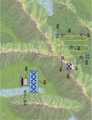
도 1은 무선 충전 드론을 이용한 촬영 시스템의 예시적인 구성을 도시한 도면이다.1 is a diagram showing an exemplary configuration of a photographing system using a wireless charging drone.
도 1에 따르면, 촬영 시스템은 다수의 촬영 드론(100), 다수의 대공표지판 드론(200), 하나 이상의 허브 드론(300), 관제 장치(400) 및 충전판(500)을 포함한다. 도 1의 촬영 시스템은 설계 변경에 따라 일부의 구성 요소가 생략되거나 다른 구성 요소가 더 포함될 수도 있다. 예를 들어, 허브 드론(300) 등은 촬영 대상의 지역적인 특색에 따라 촬영 시스템에서 생략될 수도 있다.According to FIG. 1, the photographing system includes a plurality of photographing
촬영 시스템의 구성 요소를 살펴보면, 충전판(500)은 하나 이상의 촬영 드론(100)들을 무선을 통해 충전한다. 충전판(500)은 다수의 촬영 드론(100)들 각각의 이륙과 착륙을 위한 지점으로 이용되고 나아가 촬영 드론(100)의 착륙 후에는 촬영 드론(100)의 배터리(150)를 무선으로 충전할 수 있도록 구성된다.Looking at the components of the photographing system, the charging
촬영 드론(100)은 관제 장치(400)의 제어에 따라 설정된 지역 내의 영상을 촬영한다. 촬영 드론(100)은 구비된 배터리(150)를 이용하여 비행할 수 있고 구비된 카메라 모듈(160)을 이용하여 특정 지역 내의 영상을 촬영하고 내부의 비휘발성 메모리에 저장한다. 촬영 드론(100)은 충전판(500)으로부터 공급되는 전원으로부터 구비된 배터리 전원을 충전할 수 있다. 촬영 드론(100)은 무선 충전 방식을 통해 구비된 배터리 전원을 충전 가능하다. 그 외, 촬영 드론(100)은 유선 충전 방식을 더 이용하여 배터리 전원을 충전할 수도 있다.The photographing
본 발명에 따른 촬영 시스템은 다수의 촬영 드론(100)을 포함한다. 예를 들어, 촬영 시스템은 3개 또는 4개의 촬영 드론(100)을 포함할 수 있다. 각각의 촬영 드론(100)은 관제 장치(400) 등의 제어에 따라 일정 영역(지역) 내를 계속 촬영할 수 있도록 구성된다.The photographing system according to the present invention includes a plurality of photographing
예를 들어, 하나의 촬영 드론(100)은 충전판(500)으로부터 이륙하여 촬영(비행) 시간 동안 설정된 지역(도 1의 (a) 참조)을 촬영하고 후속하는 다른 촬영 드론(100)이 이후에 충전판(500)으로부터 이륙하여 설정된 동일 지역 내의 영상을 촬영 시간 동안 촬영한다. 촬영이 끝나 회귀하여 착륙한 촬영 드론(100)들은 무선 충전을 통해 내부 배터리(150)를 재충전할 수 있다.For example, one
대공표지판 드론(200)은 촬영 드론(100)에 의해 촬영이 이루어질 설정 지역 내로 이동하여 설정 지역 내의 특정 위치에 설치되며 설치된 위치에서의 위치 데이터를 무선으로 송출한다.The
예를 들어, 대공표지판 드론(200)들 각각은 직사각형이나 정사각형의 설정 지역 내(예를 들어 500m*500m 영역)의 4 귀퉁이 지점과 중앙 지점에 착륙(설치)되고 해당 지점에서 GPS 신호를 이용하여 결정되는 위치 데이터를 무선을 통해 송출한다. 송출되는 무선신호는 관제 장치(400)가 직접 수신하거나 허브 드론(300)을 경유하여 관제 장치(400)가 수신 가능하다.For example, each of the anti-aircraft sign drones 200 is landed (installed) at four corner points and center points within a rectangular or square set area (for example, 500m*500m area), and uses GPS signals at that point. The determined location data is transmitted via wireless. The transmitted wireless signal may be directly received by the
본 발명에 따른 촬영 시스템은 다수의 대공표지판 드론(200)을 포함하는 데, 예를 들어 5개 이상의 대공표지판 드론(200)을 포함할 수 있다. 예를 들어 4개의 대공표지판 드론(200)은 직사각형의 네 모서리 위치에 각각 설치되어 해당 위치에서 측정된 위치 데이터를 송출하고 1개 또는 2개의 대공표지판 드론(200)은 설정 지역내의 중앙의 한 지점 또는 설정 지역 내의 임의의 두 지점에 설치되어 해당 위치에서 측정된 위치 데이터를 무선으로 송출한다.The photographing system according to the present invention includes a plurality of anti-aircraft sign drones 200, and for example, may include five or more anti-aircraft sign drones 200. For example, four anti-aircraft sign drones 200 are installed at each of the four corners of a rectangle to transmit positional data measured at the corresponding position, and one or two anti-aircraft sign drones 200 are located at one point in the center of the set area. Alternatively, it is installed at two arbitrary points within a set area and wirelessly transmits the location data measured at that location.
대공표지판 드론(200)은 오지, 산간 지역, 습지 등 인력에 의한 접근이 어려운 지역에 착지하여 이용될 수 있다. 촬영 지역의 면적에 따라 대공표지판 드론(200)의 개수가 많을수록 3D 맵핑시에 오차를 줄여 유리하다.The
촬영 시스템에 더 포함될 수 있는 허브 드론(300)은 무선 통신을 통해 대공표지판 드론(200)으로부터 위치 데이터를 무선으로 수신한다. 허브 드론(300)은 수신된 위치 데이터를 포함하는 중계 데이터를 무선 통신을 통해 관제 장치(400)로 전송한다.The
허브 드론(300)은 위치 데이터를 포함하는 무선통신 패킷에서 위치 데이터를 추출하고 대공표지판 드론(200)의 식별자와 위치 데이터를 포함하는 무선 통신 패킷을 구성하여 관제 장치(400)로 전송할 수 있다. 위치 데이터는 위도 데이터 및 경도 데이터와 나아가 고도 데이터를 나타내거나 포함한다.The
허브 드론(300)은 하나 이상의 대공표지판 드론(200)으로부터의 위치 데이터를 각각 수신하고 각 대공표지판 드론(200)의 위치 데이터에 대응하는 중계 데이터를 구성하여 관제 장치(400)로 전송하고 관제 장치(400)로부터의 제어 데이터에 따라 대응하는 대공표지판 드론(200)으로 해당 제어 데이터를 무선으로 전송할 수 있다.The
본 촬영 시스템에서 이용 가능한 허브 드론(300)은 대공표지판 드론(200)과 관제 장치(400) 사이에 직접적인 무선 통신이 불가능한 경우에 바람직하게 이용된다. 허브 드론(300)은 설정된 촬영 영역 내나 그 인접하는 위치에 고정될 수 있다. 예를 들어, 허브 드론(300)은 촬영 설정 지역 내나 인접 지역에서 가장 높은 고도의 위치에 고정 설치되거나 촬영 설정 지역 내의 특정 지역(예를 들어 중앙의 지점)의 상공에 호버링을 통해 고정된다. 허브 드론(300)은 무선신호 중계 모듈(360)을 포함하여 고출력의 무선신호를 출력 가능하다.The
관제 장치(400)는 촬영 드론(100) 등을 제어한다.The
관제 장치(400)는 예를 들어 노트북, 개인용 컴퓨터, 서버 프레임, 스마트폰, 태블릿 PC 등일 수 있다. 관제 장치(400)는 드론들과 무선 통신 가능한 통신 인터페이스와 드론들을 제어하기 위한 제어 프로그램을 저장하는 비휘발성 메모리, 제어 프로그램을 수행하는 프로세서, 사용자 입력을 수신하는 입력 인터페이스, 각종 상태나 결과를 출력하는 출력 인터페이스를 구비한다.The
관제 장치(400)는 제어 프로그램을 수행하여 촬영 드론(100)과 각종 데이터를 송수신할 수 있다. 관제 장치(400)는 촬영을 진행하고 있는 촬영 드론(100)으로부터 각종 상태 정보를 포함하는 무선 통신 패킷을 수신할 수 있다.The
예를 들어, 관제 장치(400)는 촬영 진행에 따라 비행 중인 촬영 드론(100)의 배터리 상태, 기체상태, 현재 위치 정보 등을 수신하여 이상 여부나 충전판(500)으로의 회귀 여부 등을 결정할 수 있고 비행 경로를 확인 가능하다. 또한, 관제 장치(400)는 촬영 드론(100)의 이착륙의 오류 등을 감지하거나 비행 로그 파일이나 영상 파일을 촬영 드론(100)으로부터 수신(예를 들어, USB 인터페이스 등을 이용하여 추출)할 수 있다.For example, the
관제 장치(400)는 촬영 드론(100), 대공표지판 드론(200) 및/또는 허브 드론(300)과 무선 통신 가능한데 LTE나 UHF 통신 방식을 혼용하여 해당 드론과 통신 가능하다. 관제 장치(400)는 관리자의 설정에 따라 LTE 통신 방식이나 UHF 통신 방식으로 설정하여 해당 드론과 통신하거나 자동으로 해당 드론과의 수신 감도를 감지하여 수신 감도가 지정된 감도 이하인 경우에 자동으로 다른 통신 방식으로 전환할 수 있다.The
또한, 관제 장치(400)는 충전판(500)에 착륙한 촬영 드론(100)들로부터 충전 상태 정보를 유선 또는 무선 통신 등을 통해 수신한다. 관제 장치(400)는 수신된 충전 상태 정보에 따라 현재 촬영(비행) 중인 촬영 드론(100)에 후속하여 촬영을 진행할 촬영 드론(100)을 착륙한 촬영 드론(100)들 중에서 결정하고 결정된 촬영 드론(100)의 비행을 제어한다.In addition, the
예를 들어, 관제 장치(400)는 충전판(500)에 충전중인 촬영 드론(100)들로부터의 충전 상태 정보(배터리 상태)를 유선이나 무선 통신을 통해 수신한다. 관제 장치(400)는 충전 상태가 완충인 촬영 드론(100)들 중에서 하나의 촬영 드론(100)을 후속 비행과 그에 따른 촬영을 진행할 촬영 드론(100)으로 결정한다.For example, the
관제 장치(400)는 현재 촬영중인 촬영 드론(100)으로부터 수신되는 상태 정보에 따라 배터리 상태가 임계치 이하인 경우에 현재 촬영 드론(100)의 회귀 요청을 나타내는 무선 통신 패킷을 전송하고 완충인 촬영 드론(100) 중 결정된 촬영 드론(100)에 비행과 촬영을 요청하는 무선 통신 패킷을 전송한다. 촬영중인 촬영 드론(100)은 충전판(500)으로 회귀하여 착륙하고 신규의 촬영 드론(100)이 이륙하여 설정된 동일한 지역 내를 촬영할 수 있다.The
그에 따라, 본 발명에 따른 촬영 시스템은 드론을 이용한 촬영의 중단 없이 연속적으로 계속 촬영을 진행할 수 있고 3대에서 4대의 촬영 드론(100)의 충전과 촬영의 반복을 통해 계속 특정 지역의 촬영이 가능하다.Accordingly, the photographing system according to the present invention can continuously shoot without interruption of shooting using drones, and it is possible to continuously shoot a specific area through charging and repetition of shooting of 3 to 4
관제 장치(400)는 촬영 드론(100)으로 촬영될 지역의 위치 범위를 유선이나 무선으로 설정할 수 있고 촬영시 각종 제어( 데이터)를 무선 통신을 통해 송신하고 그 응답이나 상태 데이터를 무선 통신을 통해 수신 가능하다.The
촬영 시스템의 관제 장치(400) 및 충전판(500)은 이동 가능하다. 예를 들어, 관제 장치(400) 및 충전판(500)은 차량의 내부나 차량의 외부에 설치되어 차량을 통해 이동 가능하다. 관제 장치(400)는 촬영 드론(100)으로 회귀 요청을 무선 통신을 통해 전송할 수 있다. 차량 등에 의해 관제 장치(400)와 충전판(500)을 포함하는 베이스캠프가 이동 가능한 경우에, 회귀 요청은 회귀 위치를 포함할 수 있다. 회귀 위치는 위도 및 경도 데이터를 포함할 수있 고 이 회귀 위치는 관제 장치(400)에 구비된 GPS 센서를 이용하여 결정될 수 있다.The
관제 장치(400)는 차량의 이동에 따라 변경되는 회귀 위치를 포함하는 무선 통신 패킷을 비행중인 촬영 드론(100)으로 전송한다. 비행중인 촬영 드론(100)은 수신된 회귀 위치의 충전판(500)의 이착륙 영역(510)에 착륙을 시도한다. 각각의 촬영 드론(100)은 특정 이착륙 영역(510)에서 이륙하고 이륙한 해당 이착륙 영역(510)에 착륙을 시도한다.The
도 2는 충전판(500)의 구성의 예를 도시한 도면이다.2 is a view showing an example of the configuration of the charging
도 2의 (a)의 충전판(500)의 (표면의) 외형을 도시한 도면이다 도 2의 (b)는 충전판(500)의 내부 구조를 도시한 도면이다.FIG. 2(a) is a view showing the outer shape (of the surface) of the charging
도 2의 (a)에서 알 수 있는 바와 같이, 충전판(500)은 다수의 이착륙 영역(510)을 가진다. 다수의 이착륙 영역(510)은 충전판(500)의 표면에 구성되고 각각의 이착륙 영역(510)은 이착륙 표시(511)를 포함한다. 각각의 이착륙 영역(510)은 촬영 드론(100)이 이륙하거나 착륙하기 위해서 이용되는 충전판(500)의 표면 영역이다. 각 이착륙 영역(510)에는 하나의 촬영 드론(100)이 이륙하거나 착륙할 수 있다. 충전판(500)은 다수의 이착륙 영역(510)을 가져 다수의 촬영 드론(100)이 이륙하거나 착륙 가능하다. 예를 들어, 충전판(500)은 4개의 이착륙 영역(510)으로 분할되어 4대의 촬영 드론(100)을 동시에 탑재할 수 있다.As can be seen from (a) of Figure 2, the charging
한 이착륙 영역(510)의 이착륙 표시(511)는 다른 이착륙 영역(510)의 이착륙 표시(511)와는 서로 다르다. 즉, 각 이착륙 영역(510)에 대응하는 각각의 이착륙 표시(511)는 다른 이착륙 영역(510)에 대응하는 이착륙 표시(511)와는 다르도록 구성되고 적어도 촬영 드론(1001)에 의해 촬영된 영상 이미지에서 인식되는 형상이 서로 다르도록 구성된다. 이착륙 표시(511)는 바람직하게는 대응하는 이착륙 영역(510) 내에 존재한다.The take-off and landing marks 511 of one take-off and
이착륙 표시(511)는 숫자, 문자 등의 조합으로 표현될 수 있다. 또는 이착륙 표시(511)는 이착륙 영역(510)에 대응하고 충전판(500)에 더 포함 가능한 태양전지판(530)의 태양전지 셀(531)의 형상을 이용하여 구성되는 표시일 수 있다.The take-off and landing marks 511 may be represented by a combination of numbers and letters. Alternatively, the take-off and
특정 하나의 이착륙 영역(510)에는 2개의 태양전지판(530)이 있을 수 있고 각각의 태양전지판(530)은 격자 형태로 다수의 태양전지 셀(531)이 존재한다(도 2의 (a) 참조).There may be two
예를 들어, 직사각형 형상의 하나의 태양전지판(530)은 가로 측으로 8개, 세로 측으로 9개의 태양전지 셀(531)을 가져 총 72개의 태양전지 셀(531)을 가질 수 있고 하나의 이착륙 영역(510)은 총 144개의 태양전지 셀(531)을 가질 수 있다.For example, one
각각의 이착륙 영역(510)의 태양전지 셀(531)들 중 서로 다른 위치의 태양전지 셀(531)들에 특정한 마킹을 표시하여 각각의 이착륙 영역(510)이 서로 다른 이착륙 표시(511)를 가질 수 있다(도 6 참조). 마킹은 예를 들어 태양전지 셀(531)을 막거나 가리기 위한 부착물로 구성될 수 있다. 서로 다른 하나 이상의 마킹으로 구성되는 이착륙 표시(511)를 통해 촬영 드론(100)은 특정 이착륙 영역(510)에 이착륙 가능하다. 예를 들면 도 6에 도시된 바와 같이, 이착륙 표시(511)는 단일 마킹, 이웃하는 2개의 마킹, 거리를 두고 배치된 2개의 마킹, 대각으로 배치된 2개의 마킹으로 서로 구분될 수 있다.By displaying specific markings on the
도 2의 (b)에서 알 수 있는 바와 같이, 충전판(500)은 강화 유리판(520), 충전 패드(540), ESS 배터리(550) 및 제어 유닛(560)(도면 미도시)을 포함하고 나아가 태양전지판(530)을 더 포함할 수 있다. 설계 예에 따라, 태양전지판(530)을 포함하는 태양전지 모듈이 별도로 구성될 수 있다. 충전판(500)은 촬영 드론(100)의 이착륙과 착륙한 촬영 드론(100)의 충전을 위해 이용된다.As can be seen in (b) of Figure 2, the charging
여기서, 도 2의 (b)는 충전판(500)의 수직 단면상에서 각 구성 요소 간의 상대적인 위치나 배열을 나타내는 도면인데, ESS 배터리(550) 등은 충전판(500)의 표면적과 같은 크기(면적)를 가질 필요는 없다.Here, (b) of FIG. 2 is a view showing the relative position or arrangement between each component on the vertical cross-section of the charging
충전판(500)의 내부 구성요소를 살펴보면, 강화 유리판(520)은 충전판(500)의 표면을 구성하여 촬영 드론(100)의 이착륙을 가능토록 한다. 강화 유리판(520)은 촬영 드론(100)의 착륙시에 편평도를 제공할 수 있는 구조물로서 이착륙을 위한 표면을 촬영 드론(100)에 제공한다. 여기서, 강화 유리판(520)의 강화 유리는 충전 패드(540)를 통한 촬영 드론(100)의 충전시에 자기장에 영향을 미치지 않거나 최소화할 수 있는 재질이다.Looking at the internal components of the charging
충전판(500)의 일 구성 요소로서 더 포함될 수 있는 태양전지판(530)은 태양으로부터의 태양에너지를 전기 에너지를 변환하여 출력한다. 출력되는 전기 에너지는 충전판(500)에 내장된 ESS 배터리(550)를 충전할 수 있다. 태양전지판(530)은 강화 유리판(520)과 충전 패드(540) 사이에 바람직하게 위치한다.The
충전 패드(540)는 촬영 드론(100)으로 무선 전원을 출력한다. 충전 패드(540)는 코일과 무선전원 출력 회로를 포함하여 제어 유닛(560)으로부터의 제어에 따라 지정 레벨의 전원을 무선으로 출력 가능하다. 충전판(500)은 다수의 충전 패드(540)를 포함할 수 있다. 각각의 충전 패드(540)는 각각의 이착륙 영역(510)에 대응하는 위치의 아래에 설치되어 각 이착륙 영역(510)의 각 촬영 드론(100)으로 무선 전원을 출력할 수 있다. 이와 같이, 충전판(500)은 복수의 촬영 드론(100) 각각으로 무선 전원을 출력하고 복수의 이착륙 영역(510) 내에 각각 위치하는 복수의 충전 패드(540)를 포함할 수 있다.The
ESS(Energy storage system) 배터리(550)는 촬영 드론(100)으로 출력될 전원을 저장한다. ESS 배터리(550)는 충전판(500)에 착륙되는 모든 촬영 드론(100)을 동시에 충전 가능한 충전용량을 가진다. 예를 들어, 충전판(500)이 4대를 수용할 수 있고 각 촬영 드론(100)이 30W의 배터리 용량을 가지는 경우, ESS 배터리(550)는 120W 이상의 충전용량을 가진다.The ESS (Energy storage system)
제어 유닛(560)은 충전판(500)을 제어한다. 제어 유닛(560)은 마이컴, CPU, MPU, 중앙 처리 장치 등의 제어 프로세서, 제어 프로세서에서 수행되는 프로그램을 저장하는 비휘발성 메모리, 각 구성 요소를 제어하기 위한 회로를 포함하여 각 구성 요소를 제어한다. 제어 유닛(560)은 충전판(500) 내부에 구성되거나 충전판(500) 외부에 결합할 수 있다.The control unit 560 controls the charging
제어 유닛(560)은 구비된 유선 또는 무선 통신 인터페이스를 통해 충전판(500)에 착륙한 촬영 드론(100) 각각으로부터 배터리 상태 데이터를 수신할 수 있다. 제어 유닛(560)은 무선 통신을 통해 직접 각 촬영 드론(100)으로부터 배터리 상태 데이터를 수신하거나 유선 통신을 통해 관제 장치(400)로부터 각 촬영 드론(100)의 배터리 상태 데이터를 수신한다.The control unit 560 may receive battery status data from each of the photographing
배터리 상태 데이터는 예를 들어, 완충을 나타내거나 배터리 충전 상태(예를 들어 충전 퍼센티지) 등을 나타낼 수 있다. 제어 유닛(560)은 각 촬영 드론(100)으로부터 수신된 배터리 상태에 따라 촬영 드론(100)이 착륙한 이착륙 영역(510)에 대응하는 충전 패드(540)를 제어하여 충전판(500)의 각각의 촬영 드론(100)의 배터리(150)를 충전 제어할 수 있다.The battery status data may indicate, for example, full charge, or the state of charge of the battery (eg, charge percentage). The control unit 560 controls the
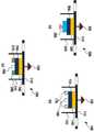
도 3은 본 발명에서 이용되는 드론의 구성의 예를 도시한 도면이다.3 is a diagram showing an example of a configuration of a drone used in the present invention.
도 3의 (a)는 허브 드론(300)의 구성을 나타낸 예이고, 도 3의 (b)는 촬영 드론(100)의 구성의 예이고 도 3의 (c)는 대공표지판 드론(200)의 구성의 예이다.Figure 3 (a) is an example showing the configuration of the
도 3을 통해 각각의 드론의 구성을 살펴보면, 허브 드론(300)은 프레임(310), 지지대(320), GPS 모듈(330), 비행제어 모듈(340), 배터리(350), 무선신호 중계 모듈(360)을 포함한다.Looking at the configuration of each drone through FIG. 3, the
프레임(310)은 허브 드론(300)의 외형을 구성한다. 프레임(310)을 통해 각종 모듈들이 지지되고 결합된다. 지지대(320)는 허브 드론(300)의 착륙시에 허브 드론(300)을 고정(착지)시킨다.The
GPS 모듈(330)은 GPS 위성으로부터의 GPS 신호를 캡쳐링하고 GPS 신호에 대응하는 GPS 데이터를 추출한다. GPS 모듈(330)은 GPS 신호의 캐리어 주파수에 동기화되어 GPS 신호를 캡쳐링 가능한 안테나를 구비하고 안테나를 통해 수신된 여러 GPS 위성으로부터의 GPS 신호에 따라 현재 위치를 나타내는 GPS 데이터를 결정할 수 있다.The
비행제어 모듈(340)(Flight Control Module)은 허브 드론(300)의 비행을 제어하고 각종 데이터를 무선으로 송수신한다.The
배터리(350)는 허브 드론(300)에서 필요한 전원을 출력한다. 배터리(350)는 다수의 배터리 셀로 구성된다.The
무선신호 중계 모듈(360)은 대공표지판 드론(200)의 위치 데이터를 포함하는 중계 무선신호를 관제 장치(400)로 송출 가능하다. 무선신호 중계 모듈(360)은 대공표지판 드론(200)으로부터의 무선 위치 데이터를 수신하고 수신된 대공표지판 드론(200)의 위치 데이터를 포함하는 중계 데이터를 구성하여 관제 장치(400)로 전송할 수 있다.The wireless
허브 드론(300)은 프레임(310)으로부터 수직 방향 아래로 비행제어 모듈(340), 배터리(350) 및 무선신호 중계 모듈(360)을 탑재하도록 구성된다.The
여기서, 프레임(310)과 비행제어 모듈(340)은 일체로 구성된다. 일반적으로 알려진 드론들은 프레임의 고정판에 비행제어 모듈을 부착하도록 구성되나 본 발명에 따른 비행제어 모듈은 프레임 자체에 일체로 내장될 수 있다. 그에 따라 본 발명에 따른 허브 드론(300)은 그 무게를 획기적으로 줄일 수 있고 비행 시간을 상대적으로 늘릴 수 있다.Here, the
촬영 드론(100)은 프레임(110), 지지대(120), GPS 모듈(130), 비행제어 모듈(140), 배터리(150), 카메라 모듈(160) 및 무선전원 수신 모듈(170)을 포함한다.The
프레임(110)은 촬영 드론(100)의 외형을 구성한다. 프레임(110)을 통해 각종 모듈들이 지지되고 결합된다. 지지대(120)는 촬영 드론(100)의 착륙시에 촬영 드론(100)을 고정(착지)시킨다.The
GPS 모듈(130)은 GPS 위성으로부터의 GPS 신호를 캡쳐링하고 GPS 신호에 대응하는 GPS 데이터를 추출한다. GPS 모듈(130)은 GPS 신호의 캐리어 주파수에 동기화되어 GPS 신호를 캡쳐링 가능한 안테나를 구비하고 안테나를 통해 수신된 여러 GPS 위성으로부터의 GPS 신호에 따라 현재 위치를 나타내는 GPS 데이터를 결정할 수 있다.The
비행제어 모듈(140)(Flight Control Module)은 촬영 드론(100)의 비행을 제어하고 각종 데이터를 무선으로 송수신한다. 비행제어 모듈(140)은 GPS 모듈(130)로부터 GPS 신호를 인식하고 인식된 GPS 신호에 대응하는 GPS 데이터를 추출하거나 GPS 데이터를 수신한다. 비행제어 모듈(140)은 카메라 모듈(160)을 통해 설정된 지역의 이미지를 캡쳐링하고 캡쳐링된 이미지를 GPS 데이터와 함께 내장된 비휘발성 메모리(예를 들어 낸드 플래쉬, SD 카드 메모리, USB 메모리 등)에 저장한다.The
비행제어 모듈(140)은 현재 추출되거나 인식된 GPS 데이터를 비행제어 모듈(140)에 내장되거나 외장된 무선통신 모듈을 통해 주기적으로 관제 장치(400)로 전송한다. 또한, 비행제어 모듈(140)은 내장된 배터리(150)의 배터리 상태 데이터를 무선통신 모듈을 통해 주기적으로 또는 배터리 상태 값에 따라 관제 장치(400)로 전송할 수 있다. 배터리 상태 데이터는 배터리(150)의 현재 배터리량이나 현재 배터리량의 퍼센티지 등을 나타낼 수 있다.The
배터리(150)는 촬영 드론(100)에서 필요한 전원을 출력한다. 배터리(150)는 3~4개 정도의 배터리 셀로 구성된다. 무선전원 수신 모듈(170)은 충전판(500)의 충전 패드(540)로부터 송출되는 무선 전원을 수신한다. 무선전원 수신 모듈(170)은 카메라 모듈(160) 주위에 코일 등을 포함하여 설치될 수 있다.The
촬영 드론(100)의 무선전원 수신 모듈(170)과 충전판(500)의 충전 패드(540)는 무선전원의 수신과 송신을 위한 회로를 구성한다. 무선전원 수신 모듈(170)과 충전 패드(540)는 자기장 유도에 따른 회로를 구성할 수 있다. 무선전원 수신 모듈(170)은 같은 높이에 설치되는 카메라 모듈(160) 주위에 배치되어 충전 패드(540)와 근접하여 무선 전원을 수신할 수 있다.The wireless
카메라 모듈(160)은 설정된 지역 내에서 촬영 드론(100)의 비행중에 노출된 이미지를 캡쳐링한다. 카메라 모듈(160)은 렌즈와 가시광선, 자외선 및/또는 적외선 센서를 등을 구비하여 비행제어 모듈(140)의 제어에 따라 주기적으로 영상 이미지를 캡쳐링할 수 있다. 비행제어 모듈(140)은 캡쳐링된 이미지를 내장된 비휘발성 메모리 등에 저장한다.The
촬영 드론(100)은 도 3의 (b)에서 알 수 있는 바와 같이 프레임(110)으로부터 수직 방향 아래로 비행제어 모듈(140), 배터리(150) 및 카메라 모듈(160)을 포함하고 카메라 모듈(160) 주위에 설치된 무선전원 수신 모듈(170)을 또한 포함한다.The
여기서, 프레임(110)과 비행제어 모듈(140)은 일체로 구성된다. 일반적으로 알려진 드론들은 프레임의 고정판에 비행제어 모듈을 부착하도록 구성되나 본 발명에 따른 비행제어 모듈은 프레임 자체에 일체로 내장될 수 있다. 그에 따라 본 발명에 따른 촬영 드론(100)은 그 무게를 획기적으로 줄일 수 있고 비행 시간을 상대적으로 늘릴 수 있다.Here, the
대공표지판 드론(200)은 프레임(210), 지지대(220), GPS 모듈(230), 비행제어 모듈(240), 배터리(250), 카메라 모듈(260), 라이다 센서(270)와 소나 센서(280)를 포함한다.The
프레임(210)은 대공표지판 드론(200)의 외형을 구성한다. 프레임(210)을 통해 각종 모듈들이 지지되고 결합된다. 지지대(220)는 대공표지판 드론(200)의 착륙시에 대공표지판 드론(200)을 고정(착지)시킨다.The
GPS 모듈(230)은 GPS 위성으로부터의 GPS 신호를 캡쳐링하고 GPS 신호에 대응하는 GPS 데이터를 추출한다. GPS 모듈(230)은 GPS 신호의 캐리어 주파수에 동기화되어 GPS 신호를 캡쳐링 가능한 안테나를 구비하고 안테나를 통해 수신된 여러 GPS 위성으로부터의 GPS 신호에 따라 현재 위치를 나타내는 GPS 데이터를 결정할 수 있다.The
비행제어 모듈(240)(Flight Control Module)은 대공표지판 드론(200)의 비행을 제어하고 각종 데이터를 무선으로 송수신한다. 비행제어 모듈(240)은 GPS 모듈로부터 GPS 신호를 인식하고 인식된 GPS 신호에 대응하는 GPS 데이터를 추출한다. 비행제어 모듈(240)은 주기적으로 인식된 GPS 데이터를 비행제어 모듈(240)에 내장되거나 외장된 무선통신 모듈을 통해 관제 장치(400)로 전송한다. 대공표지판 드론(200)으로부터 전송되는 GPS 데이터와 대공표지판 드론(200)의 식별자를 포함하는 무선 통신 패킷은 허브 드론(300)을 통해 관제 장치(400)로 전송될 수 있다.The
배터리(250)는 대공표지판 드론(200)에서 필요한 전원을 출력한다. 배터리(250)는 3~4개 정도의 배터리 셀로 구성된다. 카메라 모듈(260)은 카메라 센서를 통해 노출된 이미지를 캡쳐링한다. 카메라 모듈(260)은 렌즈와 가시광선, 자외선 및/또는 적외선 센서를 등을 구비하여 영상 이미지를 캡쳐링할 수 있다.The
라이다(Lidar) 센서(270)와 소나(Sonar) 센서(280)는 대공표지판 드론(200)의 설정된 지역 내의 특정 지점(모서리 지점)에 착륙시에 이용 가능하다. 비행제어 모듈(240)은 관제 장치(400)의 제어에 따라 지정된 지점의 착륙시에 라이다 센서(270)와 소나 센서(280), 나아가 카메라 모듈(260)로부터의 이미지를 이용하여 임의의 착륙 지점(습지나, 산악지형 등)과의 거리, 지형, 유형 등을 확인하여 안전하게 착륙을 시도할 수 있다. 대공표지판 드론(200)은 필요에 따라 원격의 관제 장치(400)로부터의 제어에 따라 착륙을 시도할 수도 있다.The
대공표지판 드론(200)은 도 3의 (c)에서 알 수 있는 바와 같이 프레임(210)으로부터 수직 방향 아래로 비행제어 모듈(240), 배터리(250) 및 카메라 모듈(260)을 포함하고 카메라 모듈(260) 주위에 설치된 소나 센서(280)와 라이다 센서(270)를 포함한다.The
여기서, 프레임(210)과 비행제어 모듈(240)은 일체로 구성된다. 일반적으로 알려진 드론들은 프레임의 고정판에 비행제어 모듈을 부착하도록 구성되나 본 발명에 따른 비행제어 모듈은 프레임 자체에 일체로 내장될 수 있다. 그에 따라 본 발명에 따른 대공표지판 드론(200)은 그 무게를 획기적으로 줄일 수 있고 비행 시간을 상대적으로 늘릴 수 있다.Here, the
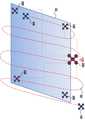
도 4는 설정된 지역내에서 드론의 배치와 동작을 설명하는 예시적인 도면이다.4 is an exemplary diagram for explaining the arrangement and operation of drones within a set area.
촬영 드론(100)에 의해 촬영이 이루어지기 위한 설정 지역(도 4의 (a) 참조)은 관제 장치(400)에 의해서 촬영 드론(100)들과 대공표지판 드론(200)들 및 허브 드론(300)들에 설정된다. 설정 지역은 예를 들어 500m*500m 크기를 가지는 지역일 수 있고 위도와 경도 및 고도로 표현되거나 설정된다. 각각의 드론들은 할당된 기능에 따라 설정 지역 내를 촬영하거나 임의의 위치에 고정된다.The set area (refer to (a) of FIG. 4) for shooting by the
예를 들어, 대공표지판 드론(200)들 각각은 설정 지역 내의 각 모서리 지점에 착륙하여 고정된다. 허브 드론(300)은 설정 지역 내의 상공에 또는 인접 지역의 높은 지점에 고정된다. 허브 드론(300)은 대공표지판 드론(200)으로부터의 위치 데이터를 포함하는 무선 통신 패킷을 인식하고 인식된 위치 데이터와 대공표지판 드론(200)의 식별자를 포함하는 중계 데이터를 구성하여 관제 장치(400)로 전송한다.For example, each of the anti-aircraft sign drones 200 is fixed by landing at each corner point in the set area. The
촬영 드론(100)은 설정 지역 내의 상공(예를 들어, 100m ~ 300m 사이의 상공)에서 설정된 비행 항로(도 4의 (b) 참조)에 따라 비행하면서 구비된 카메라 모듈(160)을 통해 이미지를 캡쳐링한다. 촬영 드론(100)은 주기적으로 관제 장치(400)와 통신 가능하고 예를 들어 현재 위치를 나타내는 GPS 데이터 및/또는 측정된 배터리 상태 데이터를 나타내거나 포함하는 무선통신 패킷을 무선통신 모듈을 통해 관제 장치(400)로 전송한다.The photographing
또한, 촬영 드론(100)은 관제 장치(400)로부터 수신되는 제어 데이터에 따라 비행 경로를 변경하거나 충전판(500)(베이스캠프)으로 회귀할 수 있다. 촬영 드론(100)은 이륙시의 충전판(500) 위치로 회귀하거나 회귀 요청을 나타내는 제어 데이터의 위치(변경되는 위치)로 비행하여 회귀할 수 있다.In addition, the photographing
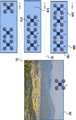
도 5는 다수의 촬영 드론(100)을 이용하여 설정 지역의 촬영을 연속적으로 진행하는 흐름을 설명하기 위한 예시적인 도면이다.5 is an exemplary diagram for explaining a flow of continuously photographing a set area using a plurality of photographing
먼저, 촬영이 이루어질 지역과 촬영 드론(100)을 준비(설정)(도 5의 "1. step" 참조)한다. 설정 과정 이전에 대공표지판 드론(200)과 허브 드론(300)은 먼저 이동하여 고정될 수 있다.First, prepare (set) the region where the photographing will be performed and the photographing drone 100 (see “1. step” in FIG. 5). Before the setting process, the
복수의 촬영 드론(100) 각각은 충전판(500)의 복수의 이착륙 영역(510)에 위치하여 이륙을 대기하고 있을 수 있다. 각 촬영 드론(100)은 충전판(500)에 대기중에 관제 장치(400)나 충전판(500)의 제어 유닛(560)의 제어에 따라 충전을 진행할 수 있다.Each of the plurality of photographing
관제 장치(400)는 촬영 드론(100)들 각각에 비행이 이루어질 설정 지역에 대한 정보와 비행 항로를 유선이나 무선을 통해 전송한다. 설정 지역의 정보는 위도와 경도를 표현되는 직사각형의 범위를 나타낼 수 있고 비행 항로는 설정 지역 내에서의 비행 경로를 나타낼 수 있다. 그 외, 관제 장치(400)는 촬영 드론(100)에 이착륙과 비행에 필요한 각종 정보(비행 고도, 촬영 주기, 회귀 정보 등)를 설정한다. 관제 장치(400)는 각각의 촬영 드론(100)들로부터 내장된 배터리(150)의 충전 상태를 나타내는 충전 상태 정보를 유선(충전판(500)의 제어 유닛(560)을 경유하여)이나 무선(촬영 드론(100)과 설정되는 무선통신 채널을 통해 직접)을 통해 수신한다.The
관제 장치(400)는 복수의 촬영 드론(100) 중 하나의 촬영 드론(100)을 현재 촬영을 진행할 촬영 드론(100)으로 결정한다. 예를 들어, 관제 장치(400)는 수신된 충전 상태 정보가 완충을 나타내는 촬영 드론(100) 중 하나의 촬영 드론(100)을 선택하고 선택된 촬영 드론(100)으로 설정 지역으로 비행 및 촬영 요청을 나타내는 제어 데이터를 유선이나 무선으로 전송한다.The
비행 및 촬영 요청의 제어 데이터를 수신한 촬영 드론(100)은 설정 지역을 촬영(도 5의 "2. step" 참조)한다.Receiving the control data of the flight and photographing request, the photographing
구체적으로, 선택된 촬영 드론(100)(예를 들어, 도 5의 '1' 촬영 드론(100))은 GPS 모듈(130)이나 수신된 회귀 정보(위치)에 따라 회귀가 이루어질 회귀 위치를 결정한다. 촬영 드론(100)은 GPS 모듈(130)로부터 추출된 위도 및 경도의 GPS 데이터나 관제 장치(400)로부터 수신된 위도 및 경도의 GPS 데이터를 회귀 위치로 결정한다.Specifically, the selected photographing drone 100 (for example, the '1' photographing
촬영 드론(100)은 내장된 모터 등을 제어하여 충전판(500)의 이착륙 영역(510)으로부터 이륙을 시작한다. 촬영 드론(100)은 충전판(500)으로부터 이륙시에 충전판(500)의 현 이착륙 영역(510)의 이착륙 표시(511)를 포함하는 이미지를 카메라 모듈(160)을 통해 캡쳐링한다. 캡쳐링된 이미지에는 이착륙 영역(510)에 대응하는 고유의 이착륙 표시(511)를 포함한다. 이착륙 표시(511)는 숫자나 문자의 조합으로 구성되거나 태양전지판(530)의 태양전지 셀(531)의 형상(의 조합을) 이용하여 표현될 수 있다. 촬영 드론(100)은 이착륙 표시(511)를 포함하는 캡쳐링된 이미지를 회귀 위치와 함께 내장된 비휘발성 메모리 등에 저장한다.The photographing
이후, 촬영 드론(100)은 설정 지역으로 이동(도 5의 (a) 및 (b) 참조)하여 설정 지역 내에서 지정된 비행 항로에 따라 이동하면서 구비된 카메라 모듈(160)을 통해 계속 영상을 촬영한다.Thereafter, the
선택된 촬영 드론(100)의 비행과 촬영이 이루어지는 한편, 충전판(500)에 있는 나머지 촬영 드론(100)들은 충전판(500)에서 출력되는 무선 충전 전원에 따라 구비된 배터리(150)를 충전한다. 관제 장치(400) 및/또는 충전판(500)의 제어 유닛(560)은 촬영 드론(100)으로부터 충전 상태 정보를 수신하고 수신된 충전 상태 정보가 완충을 나타내는 경우 완충된 촬영 드론(100)에 대응하는 충전 패드(540)를 제어하여 무선 충전 전원의 출력을 중단한다. 수신된 충전 상태 정보가 완충이 아닌 경우 관제 장치(400) 및/또는 충전판(500)의 제어 유닛(560)은 촬영 드론(100)에 대응하는 충전 패드(540)를 제어하여 무선 충전 전원을 계속 출력한다.While flying and shooting of the selected
이와 같이, 하나의(또는 두 개의) 촬영 드론(100)이 비행과 촬영 중에 나머지 촬영 드론(100)들은 충전판(500)에 착지하여 공급되는 무선 전원을 이용하여 동시에 배터리(150)를 충전 가능하다.In this way, while one (or two) shooting
한편, 촬영을 진행하는 촬영 드론(100)은 설정된 지역에서 촬영을 진행하면서 주기적으로 GPS 데이터 및/또는 상태 정보를 관제 장치(400)로 전송할 수 있다. 상태 정보는 배터리 상태 데이터를 포함할 수 있다.Meanwhile, the photographing
관제 장치(400)는 배터리 상태 데이터가 설정된 임계치 이하인지를 판단하고 임계치 이하의 배터리(150)가 촬영 드론(100)에 남아 있는 경우에 후속하여 계속 촬영을 진행할 촬영 드론(100)을 충전판(500)에 남아 있는 촬영 드론(100)들 중에서 선택한다. 예를 들어, 관제 장치(400)는 수신되는 충전 상태 정보에 완충 상태인 촬영 드론(100) 중에서 하나의 촬영 드론(100)(예를 들어, 도 5의 '2')을 선택한다.The
후속하여 선택된 촬영 드론(100)은 내장된 모터 등을 제어하여 충전판(500)의 이착륙 영역(510)으로부터 이륙을 시작한다. 촬영 드론(100)은 충전판(500)으로부터 이륙시에 충전판(500)의 현 이착륙 영역(510)(도 5의 '2'의 이착륙 영역)의 이착륙 표시(511)를 포함하는 이미지를 카메라 모듈(160)을 통해 캡쳐링한다. 캡쳐링된 이미지에는 이착륙 영역(510)에 대응하는 고유의 이착륙 표시(511)를 포함하고 다른 이착륙 영역(510)에 대응하는 그 표시와는 서로 다르다. 촬영 드론(100)은 이착륙 표시(511)를 포함하는 캡쳐링된 이미지를 회귀 위치와 함께 내장된 비휘발성 메모리 등에 저장한다.Subsequently, the selected photographing
이후, 후속 촬영 드론(100)은 설정 지역으로 이동하여 설정 지역 내에서 지정된 비행 항로에 따라 이동하면서 구비된 카메라 모듈(160)을 통해 계속 영상을 촬영한다.Thereafter, the subsequent photographing
관제 장치(400)는 새로운 촬영 드론(100)의 비행 제어와 함께, 현재 촬영을 진행하고 있는 임계치 이하의 배터리(150)를 가지는 촬영 드론(100)으로 회귀 요청을 나타내거나 포함하는 제어 데이터를 무선 통신을 통해 전송한다. 회귀 요청은 회귀 위치를 더 포함할 수 있다. 관제 장치(400)가 이동 가능한 경우 회귀 요청은 관제 장치(400)에서 인식된 위치 데이터를 회귀 위치로 포함한다.The
이와 같이, 일정한 시간 동안에 하나의 촬영 드론(100)이 영상 촬영을 하는 한편, 나머지 촬영 드론(100)들은 충전판(500)에 착지하여 충전을 진행할 수 있다.As described above, while one photographing
회귀 요청을 수신한 촬영 드론(100)은 회귀 위치를 이용하여 충전판(500)으로 회귀(도 5의 "3. step" 참조)하고 이륙시의 이착륙 영역(510)에 착륙한다. 촬영 드론(100)(의 비행제어 모듈(140))은 이륙시에 캡쳐링된 이미지에서 고유의 이착륙 표시(511)를 인식한다. 촬영 드론(100)은 GPS 모듈(130)로부터 인식된 위치 데이터와 회귀 위치를 비교하여 회귀 위치로 이동하고 회귀 위치에서 충전판(500)을 인식할 수 있다.Upon receiving the return request, the photographing
또한, 촬영 드론(100)은 카메라 모듈(160)을 통해 이미지를 캡쳐링하고 캡쳐링된 이미지에서 이착륙 표시(511)를 인식하여 캡쳐링된 이미지의 이착륙 표시(511)와 이륙시 저장되거나 인식된 이착륙 표시(511)를 비교한다. 촬영 드론(100)은 비교에 따라 동일한 이착륙 표시(511)를 가지는 이착륙 영역(510)에 착륙을 이후 시도하고 착륙할 수 있다. 촬영 드론(100)은 필요에 따라 이착륙 표시의 인식과 비교 이전에 이착륙 영역들의 형상(예를 들어, 태양전지판(530)들의 결합에 따른 형상)을 선 인식할 수도 있다. 또한, 필요에 따라, 촬영 드론(100)은 관제 장치(400)에 의해 수동으로 착륙이 시도될 수도 있다.In addition, the photographing
두 번째 촬영 드론(100)이 이륙후 설정된 지역을 촬영하는 동안에, 충전판(500)에 착지한 촬영 드론(100)들은 충전판(500)의 충전 패드(540)를 통해 출력되는 무선 충전 전원에 따라 구비된 배터리(150)를 충전한다. 특히, 배터리 전원을 소진하여 회귀한 첫 번째 촬영 드론(100)은 착지 후에 구비된 충전 패드(540)를 통해 무선 전원을 공급받아 배터리(150)를 완충시킬 수 있다.While the
두 번째 촬영 드론(100)도 관제 장치(400)와 촬영 도중에 무선 통신을 수행하고 배터리 상태 데이터를 포함하는 무선통신 패킷을 관제 장치(400)로 전송하고 관제 장치(400)의 판단에 따라 회귀할 수 있다. 두 번째 촬영 드론(100)도 착륙시에 이미지를 캡쳐링하고 이륙시에 캡쳐링된 이미지의 이착륙 표시(511)와 착륙시에 캡쳐링된 이미지에서 인식되는 이착륙 표시(511)의 비교로 이륙이 이루어진 이착륙 영역(510)을 인식하고 해당 영역에 착륙을 시도할 수 있다.The
두 번째 촬영 드론(100)은 내장된 배터리(150)의 상태에 따라 일정한 시간 동안 촬영을 진행하는 한편, 나머지 촬영 드론(100)들은 충전판(500)에서 충전을 진행한다. 관제 장치(400)는 완충된 나머지 촬영 드론(100) 중에서 하나의 촬영 드론(100)을 선택하여 두 번째 촬영 드론(100)에 후속하는 촬영 드론(100)으로 선택하여 설정 지역을 계속 촬영할 수 있다.The second photographing
이와 같은 구성을 통해, 본 촬영 시스템은 촬영의 중단 없이 연속적으로 촬영 가능하다. 또한, 본 촬영 시스템은 촬영 드론(100)의 촬영 외에는 충전을 동시에 진행하여 24시간 연속적으로 그 촬영이 가능토록 한다. 촬영 드론(100)의 개수와 배터리(150)의 용량은 충전 패드(540)의 충전 시간 등에 따라 달리 구성되거나 변경될 수 있다.Through this configuration, the present photographing system can photograph continuously without interruption of photographing. In addition, the present photographing system performs charging at the same time except for photographing of the photographing
이상에서 설명한 본 발명은, 본 발명이 속하는 기술 분야에서 통상의 지식을 가진 자에게 있어 본 발명의 기술적 사상을 벗어나지 않는 범위 내에서 여러 가지 치환, 변형 및 변경이 가능하므로 전술한 실시 예 및 첨부된 도면에 의해 한정되는 것이 아니다.The present invention described above, for those of ordinary skill in the technical field to which the present invention pertains, various substitutions, modifications, and changes are possible within the scope of the technical spirit of the present invention. It is not limited by the drawings.
100 : 촬영 드론
110 : 프레임120 : 지지대
130 : GPS 모듈140 : 비행제어 모듈
150 : 배터리160 : 카메라 모듈
170 : 무선전원 수신 모듈
200 : 대공표지판 드론
210 : 프레임220 : 지지대
230 : GPS 모듈240 : 비행제어 모듈
250 : 배터리260 : 카메라 모듈
270 : 라이다 센서280 : 소나 센서
300 : 허브 드론
310 : 프레임320 : 지지대
330 : GPS 모듈,340 : 비행제어 모듈
350 : 배터리,360 : 무선신호 중계 모듈
400 : 관제 장치
500 : 충전판
510 : 이착륙 영역511 : 이착륙 표시
520 : 강화 유리판
530 : 태양전지판531 : 태양전지 셀
540 : 충전 패드550 : ESS 배터리
560 : 제어 유닛100: shooting drone
110: frame 120: support
130: GPS module 140: flight control module
150: battery 160: camera module
170: wireless power receiving module
200: anti-aircraft sign drone
210: frame 220: support
230: GPS module 240: flight control module
250: battery 260: camera module
270: lidar sensor 280: sonar sensor
300: hub drone
310: frame 320: support
330: GPS module, 340: flight control module
350: battery, 360: wireless signal relay module
400: control device
500: charging plate
510: take-off and landing area 511: take-off and landing mark
520: tempered glass plate
530: solar panel 531: solar cell
540: charging pad 550: ESS battery
560: control unit
Claims (12)
Translated fromKorean무선 충전 가능한 충전판; 및
상기 충전판에서 공급되는 전원으로부터 구비된 배터리의 전원을 무선 충전할 수 있는 복수의 촬영 드론;을 포함하고,
상기 복수의 촬영 드론 중 제1 촬영 드론은 상기 충전판으로부터 이륙하여 설정된 지역 내의 영상을 촬영하고 상기 복수의 촬영 드론 중 제2 촬영 드론은 상기 제1 촬영 드론의 촬영에 후속하여 상기 설정된 지역 내의 영상을 촬영하며,
상기 설정된 지역 내의 지정된 위치에 이동하여 설치되는 복수의 대공표지판 드론; 및
촬영이 이루어질 상기 설정된 지역 내 복수의 특정 지점에 각각 착륙한 상기 복수의 대공표지판 드론으로부터, 상기 복수의 특정 지점에서의 GPS 신호를 이용하여 결정되는 위치 데이터를 수신하고, 수신된 위치 데이터를 포함하는 중계 데이터를 관제 장치로 전송하는 허브 드론;을 더 포함하며,
상기 충전판은,
태양에너지를 전기 에너지로 변환하여 출력하는 태양전지판과,
상기 태양전지판의 위에 위치하고 상기 촬영 드론의 이착륙 표면을 제공하는 강화 유리판을 포함하는,
촬영 시스템.As a shooting system using a wireless charging drone,
Charging plate capable of wireless charging; And
Including; a plurality of shooting drones capable of wirelessly charging the power of a battery provided from the power supplied from the charging plate,
Among the plurality of photographing drones, a first photographing drone takes off from the charging plate to photograph an image within a set area, and a second photographing drone among the plurality of photographing drones captures an image within the set region following the photographing of the first photographing drone. Shooting,
A plurality of anti-aircraft sign drones installed by moving to a designated location within the set area; And
Receiving position data determined using GPS signals at the plurality of specific points from the plurality of anti-aircraft sign drones each landing at a plurality of specific points in the set area where photographing is to be performed, and including the received position data Further comprising a; hub drone for transmitting the relay data to the control device,
The charging plate,
A solar panel that converts solar energy into electrical energy and outputs it,
Including a tempered glass plate positioned on the solar panel and providing a take-off and landing surface of the photographing drone,
Shooting system.
상기 충전판은 상기 복수의 촬영 드론의 이착륙 영역을 나타내고 서로 상이한 복수의 이착륙 표시를 포함하고,
상기 복수의 촬영 드론 중 제1 촬영 드론은 상기 충전판으로부터 이륙시에 상기 충전판의 이착륙 표시를 포함하는 이미지를 캡쳐링하고 상기 충전판에 착륙시에 캡쳐링된 이미지의 이착륙 표시에 대응하는 제1 이착륙 영역에 착륙하며,
상기 복수의 촬영 드론 중 제2 촬영 드론은 상기 충전판으로부터 이륙시에 상기 충전판의 이착륙 표시를 포함하는 이미지를 캡쳐링하고 상기 충전판에 착륙시에 캡쳐링된 이미지의 이착륙 표시에 대응하는 제2 이착륙 영역에 착륙하는,
촬영 시스템.The method of claim 1,
The charging plate represents a take-off and landing area of the plurality of photographing drones and includes a plurality of take-off and landing marks different from each other,
Among the plurality of photographing drones, a first photographing drone captures an image including a take-off and landing indication of the charging plate when taking off from the charging plate, and 1 landing in the take-off and landing area,
Among the plurality of photographing drones, the second photographing drone captures an image including a take-off and landing indication of the charging plate when taking off from the charging plate, and 2 landing in the take-off and landing area,
Shooting system.
제1 시간 동안에, 상기 복수의 촬영 드론 중 제1 촬영 드론은 상기 설정된 지역 내의 영상을 촬영하고 상기 복수의 촬영 드론 중 제2 촬영 드론은 상기 충전판에서 출력되는 무선 충전 전원에 따라 구비된 배터리를 충전하고,
상기 제1 시간 이후의 제2 시간 동안에, 상기 복수의 촬영 드론 중 제2 촬영 드론은 설정된 지역 내의 영상을 촬영하고 상기 복수의 촬영 드론 중 제1 촬영 드론은 상기 충전판에서 출력되는 무선 충전 전원에 따라 구비된 배터리를 충전하는,
촬영 시스템.The method of claim 1,
During the first time, a first shooting drone of the plurality of shooting drones shoots an image within the set area, and a second shooting drone of the plurality of shooting drones is equipped with a battery provided according to the wireless charging power output from the charging plate. Recharge,
During a second time after the first time, a second shooting drone of the plurality of shooting drones captures an image within a set area, and a first shooting drone of the plurality of shooting drones is connected to the wireless charging power output from the charging plate. To charge the battery provided accordingly,
Shooting system.
상기 충전판은, 촬영 드론으로 출력될 전원을 저장하는 ESS 배터리, 상기 ESS 배터리를 충전 가능한 복수의 상기 태양전지판, 및 상기 촬영 드론으로 무선 전원을 출력하는 충전 패드를 포함하고,
상기 충전판의 표면 영역은 복수의 촬영 드론이 이착륙 가능한 복수의 이착륙 영역으로 분할되고 각각의 이착륙 영역 내에는 대응하는 서로 다른 이착륙 표시가 존재하는,
촬영 시스템.The method of claim 2,
The charging plate includes an ESS battery that stores power to be output to a photographing drone, a plurality of solar panels capable of charging the ESS battery, and a charging pad that outputs wireless power to the photographing drone,
The surface area of the charging plate is divided into a plurality of take-off and landing areas in which a plurality of photographing drones can take off and landing, and corresponding different take-off and landing marks exist in each take-off and landing area.
Shooting system.
상기 이착륙 표시는 이착륙 영역에 대응하는 상기 태양전지판의 태양전지 셀의 형상을 이용하여 구성되는 표시인,
촬영 시스템.The method of claim 4,
The take-off and landing indication is a display configured using the shape of the solar cell of the solar panel corresponding to the take-off and landing area,
Shooting system.
상기 촬영 드론은 중앙에 수직 방향으로 비행제어 모듈, 배터리, 무선전원 수신 모듈 및 카메라 모듈을 포함하고,
상기 카메라 모듈과 함께 배터리 아래에 설치되는 상기 무선전원 수신 모듈은 상기 카메라 모듈 주위에 위치하는,
촬영 시스템.The method of claim 1,
The shooting drone includes a flight control module, a battery, a wireless power receiving module and a camera module in a vertical direction at the center,
The wireless power receiving module installed under the battery together with the camera module is located around the camera module,
Shooting system.
상기 충전판은 상기 복수의 촬영 드론 각각으로 무선 전원을 출력하고 복수의 이착륙 영역 내에 각각 위치하는 복수의 상기 충전 패드를 포함하고,
상기 ESS 배터리는 상기 복수의 촬영 드론의 배터리를 상기 복수의 충전 패드를 통해 동시에 충전 가능한 충전용량을 가지는,
촬영 시스템.The method of claim 5,
The charging plate outputs wireless power to each of the plurality of photographing drones and includes a plurality of charging pads respectively positioned in a plurality of take-off and landing areas,
The ESS battery has a charging capacity capable of simultaneously charging the batteries of the plurality of photographing drones through the plurality of charging pads,
Shooting system.
상기 충전판은 상기 복수의 촬영 드론 각각으로부터 수신된 배터리 상태에 따라 상기 복수의 충전 패드를 제어하여 상기 복수의 촬영 드론 각각의 배터리를 충전 제어하는 제어 유닛을 더 포함하는,
촬영 시스템.The method of claim 7,
The charging plate further comprises a control unit for charging and controlling the batteries of each of the plurality of photographing drones by controlling the plurality of charging pads according to battery states received from each of the plurality of photographing drones,
Shooting system.
상기 관제 장치는 복수의 촬영 드론 중에서 상기 충전판에 착륙한 촬영 드론들로부터 충전 상태 정보를 수신하고 수신된 충전 상태 정보에 따라 제1 촬영 드론에 후속하여 촬영할 제2 촬영 드론을 결정하고 결정된 제2 촬영 드론의 비행을 제어하는,
촬영 시스템.The method of claim 1,
The control device receives charging status information from the shooting drones landing on the charging plate among a plurality of shooting drones, determines a second shooting drone to be photographed following the first shooting drone according to the received charging status information, and determines the second shooting drone. To control the flight of the shooting drone,
Shooting system.
상기 대공표지판 드론은 중앙에 수직 방향으로 비행제어 모듈, 배터리, 카메라 모듈 및 상기 카메라 모듈 주위에 설치되는 라이다 센서 및 소나 센서를 포함하고,
상기 허브 드론은 중앙에 수직 방향으로 비행제어 모듈, 배터리 및 무선신호 중계 모듈을 포함하고,
상기 촬영 드론은 중앙에 수직 방향으로 비행제어 모듈, 배터리, 카메라 모듈 및 상기 카메라 모듈 주위에 설치되는 무선전원 수신 모듈을 포함하는,
촬영 시스템.The method of claim 10,
The anti-aircraft sign drone includes a flight control module, a battery, a camera module, and a lidar sensor and a sonar sensor installed around the camera module in a vertical direction at the center,
The hub drone includes a flight control module, a battery and a wireless signal relay module in a vertical direction at the center,
The photographing drone includes a flight control module, a battery, a camera module, and a wireless power receiving module installed around the camera module in a vertical direction at the center,
Shooting system.
상기 관제 장치 및 상기 충전판은 차량에 설치되고,
상기 관제 장치는 차량의 이동에 따라 변경되는 회귀 위치를 비행중인 촬영 드론으로 전송하고 회귀 위치를 수신한 촬영 드론은 변경된 회귀 위치의 충전판의 대응하는 이착륙 영역에 착륙을 시도하는,
촬영 시스템.The method of claim 10,
The control device and the charging plate are installed in the vehicle,
The control device transmits a return position that is changed according to the movement of the vehicle to the shooting drone in flight, and the photographing drone receiving the return position attempts to land in a corresponding take-off and landing area of the charging plate of the changed return position,
Shooting system.
Priority Applications (1)
| Application Number | Priority Date | Filing Date | Title |
|---|---|---|---|
| KR1020180112251AKR102160734B1 (en) | 2018-09-19 | 2018-09-19 | Image taking system using wireless rechargeable drones |
Applications Claiming Priority (1)
| Application Number | Priority Date | Filing Date | Title |
|---|---|---|---|
| KR1020180112251AKR102160734B1 (en) | 2018-09-19 | 2018-09-19 | Image taking system using wireless rechargeable drones |
Publications (2)
| Publication Number | Publication Date |
|---|---|
| KR20200032964A KR20200032964A (en) | 2020-03-27 |
| KR102160734B1true KR102160734B1 (en) | 2020-09-28 |
Family
ID=69959165
Family Applications (1)
| Application Number | Title | Priority Date | Filing Date |
|---|---|---|---|
| KR1020180112251AActiveKR102160734B1 (en) | 2018-09-19 | 2018-09-19 | Image taking system using wireless rechargeable drones |
Country Status (1)
| Country | Link |
|---|---|
| KR (1) | KR102160734B1 (en) |
Cited By (2)
| Publication number | Priority date | Publication date | Assignee | Title |
|---|---|---|---|---|
| KR102263560B1 (en)* | 2020-10-29 | 2021-06-14 | 한국건설기술연구원 | System for setting ground control points using cluster RTK drones |
| KR102309787B1 (en) | 2021-03-11 | 2021-10-08 | 주식회사 미추홀공간지적 | Air panel apparatus for drone survey |
Families Citing this family (5)
| Publication number | Priority date | Publication date | Assignee | Title |
|---|---|---|---|---|
| CN111529995A (en)* | 2020-05-08 | 2020-08-14 | 江西壮龙无人机科技有限公司 | Fire extinguishing method and system based on unmanned aerial vehicle inspection |
| KR102422632B1 (en)* | 2021-03-22 | 2022-07-21 | 주식회사 드림이노베이션 | Search information sharing control system |
| CN114115306B (en)* | 2021-11-05 | 2025-02-18 | 深圳市大疆创新科技有限公司 | UAV takeoff detection method, device, UAV and storage medium |
| KR20230140336A (en) | 2022-03-29 | 2023-10-06 | 현대자동차주식회사 | Apparatus and method for controlling aerial vehicle |
| CN117944914B (en)* | 2024-03-27 | 2024-06-25 | 威泊(上海)新能源科技股份有限公司 | Air charging equipment for tunneling unmanned aerial vehicle and charging method thereof |
Citations (1)
| Publication number | Priority date | Publication date | Assignee | Title |
|---|---|---|---|---|
| JP2010233120A (en)* | 2009-03-27 | 2010-10-14 | Nec Corp | Information transmission system, distortion compensation method used for the same, and distortion compensation control program |
Family Cites Families (5)
| Publication number | Priority date | Publication date | Assignee | Title |
|---|---|---|---|---|
| KR101733677B1 (en)* | 2015-06-11 | 2017-05-08 | 주식회사 두시텍 | Apparatus and method for unmanned plane precision landing using artificial landmark and ultrasonic sensor |
| KR20170045071A (en)* | 2015-10-16 | 2017-04-26 | 조승철 | Alternating-type surveillance system and method using multiple drones |
| KR101853348B1 (en)* | 2016-08-22 | 2018-04-30 | 한국해양과학기술원 | Setting method of ground control point using drone |
| KR101866071B1 (en)* | 2016-10-17 | 2018-06-08 | 동서대학교산학협력단 | management method using unmanned drones rental system |
| KR20180077739A (en)* | 2016-12-29 | 2018-07-09 | 장문호 | Wireless power network system |
- 2018
- 2018-09-19KRKR1020180112251Apatent/KR102160734B1/enactiveActive
Patent Citations (1)
| Publication number | Priority date | Publication date | Assignee | Title |
|---|---|---|---|---|
| JP2010233120A (en)* | 2009-03-27 | 2010-10-14 | Nec Corp | Information transmission system, distortion compensation method used for the same, and distortion compensation control program |
Cited By (2)
| Publication number | Priority date | Publication date | Assignee | Title |
|---|---|---|---|---|
| KR102263560B1 (en)* | 2020-10-29 | 2021-06-14 | 한국건설기술연구원 | System for setting ground control points using cluster RTK drones |
| KR102309787B1 (en) | 2021-03-11 | 2021-10-08 | 주식회사 미추홀공간지적 | Air panel apparatus for drone survey |
Also Published As
| Publication number | Publication date |
|---|---|
| KR20200032964A (en) | 2020-03-27 |
Similar Documents
| Publication | Publication Date | Title |
|---|---|---|
| KR102160734B1 (en) | Image taking system using wireless rechargeable drones | |
| JP6755966B2 (en) | Imaging using multiple unmanned aviation vehicles | |
| KR102090170B1 (en) | Forest fire monitoring device and forest fire monitoring system using drone | |
| US11531340B2 (en) | Flying body, living body detection system, living body detection method, program and recording medium | |
| CN110537365B (en) | Information processing device, information processing method, information processing program, image processing device, and image processing system | |
| US20180275659A1 (en) | Route generation apparatus, route control system and route generation method | |
| CN106527475A (en) | Distribution network inspection unmanned aerial vehicle and inspection method thereof | |
| KR101650136B1 (en) | The apparatus of smart drone | |
| CN205150226U (en) | Air patrol system based on fuselage formula of verting rotor unmanned aerial vehicle | |
| CN112650267B (en) | Flight control method and device of aircraft and aircraft | |
| WO2018090493A1 (en) | Unmanned aerial vehicle | |
| CN107000832A (en) | UAV landing gear control method, device, UAV and system thereof | |
| EP3480118A1 (en) | Aerial vehicle landing method, aerial vehicle, and computer readable storage medium | |
| KR20180074247A (en) | System and method for detecting event using unmanned aerial vehicle | |
| US11383835B2 (en) | System and transport device for unmanned aerial vehicles | |
| CN204895881U (en) | Unmanned aerial vehicle system with thermal imaging system | |
| KR102129502B1 (en) | Cadastral survey system and method using drone | |
| CN103888738A (en) | Multisource multi-area-array GIS data acquisition platform for unmanned vehicle | |
| CN113608542B (en) | Control method and equipment for automatic landing of unmanned aerial vehicle | |
| CN205872464U (en) | Unmanned aerial vehicle system | |
| CN110162076A (en) | A kind of contact net fully-automatic intelligent cruising inspection system and method for inspecting based on unmanned plane | |
| KR101808273B1 (en) | The apparatus of smart drone with internet of things and visible light communication module | |
| CN206236228U (en) | A kind of forest fire monitoring early-warning system based on unmanned plane | |
| CN204587320U (en) | A kind of remotely sensed image is taken photo by plane system | |
| JP2024173959A (en) | Charging devices, charging systems, disaster support systems, transportation systems and pillars for unmanned aerial vehicles |
Legal Events
| Date | Code | Title | Description |
|---|---|---|---|
| PA0109 | Patent application | St.27 status event code:A-0-1-A10-A12-nap-PA0109 | |
| PA0201 | Request for examination | St.27 status event code:A-1-2-D10-D11-exm-PA0201 | |
| P22-X000 | Classification modified | St.27 status event code:A-2-2-P10-P22-nap-X000 | |
| P22-X000 | Classification modified | St.27 status event code:A-2-2-P10-P22-nap-X000 | |
| D13-X000 | Search requested | St.27 status event code:A-1-2-D10-D13-srh-X000 | |
| D14-X000 | Search report completed | St.27 status event code:A-1-2-D10-D14-srh-X000 | |
| E902 | Notification of reason for refusal | ||
| PE0902 | Notice of grounds for rejection | St.27 status event code:A-1-2-D10-D21-exm-PE0902 | |
| PG1501 | Laying open of application | St.27 status event code:A-1-1-Q10-Q12-nap-PG1501 | |
| R18-X000 | Changes to party contact information recorded | St.27 status event code:A-3-3-R10-R18-oth-X000 | |
| E13-X000 | Pre-grant limitation requested | St.27 status event code:A-2-3-E10-E13-lim-X000 | |
| P11-X000 | Amendment of application requested | St.27 status event code:A-2-2-P10-P11-nap-X000 | |
| P13-X000 | Application amended | St.27 status event code:A-2-2-P10-P13-nap-X000 | |
| P22-X000 | Classification modified | St.27 status event code:A-2-2-P10-P22-nap-X000 | |
| E701 | Decision to grant or registration of patent right | ||
| PE0701 | Decision of registration | St.27 status event code:A-1-2-D10-D22-exm-PE0701 | |
| GRNT | Written decision to grant | ||
| PR0701 | Registration of establishment | St.27 status event code:A-2-4-F10-F11-exm-PR0701 | |
| PR1002 | Payment of registration fee | St.27 status event code:A-2-2-U10-U11-oth-PR1002 Fee payment year number:1 | |
| PG1601 | Publication of registration | St.27 status event code:A-4-4-Q10-Q13-nap-PG1601 | |
| P22-X000 | Classification modified | St.27 status event code:A-4-4-P10-P22-nap-X000 | |
| P22-X000 | Classification modified | St.27 status event code:A-4-4-P10-P22-nap-X000 | |
| P22-X000 | Classification modified | St.27 status event code:A-4-4-P10-P22-nap-X000 | |
| PR1001 | Payment of annual fee | St.27 status event code:A-4-4-U10-U11-oth-PR1001 Fee payment year number:4 | |
| R18-X000 | Changes to party contact information recorded | St.27 status event code:A-5-5-R10-R18-oth-X000 | |
| P22-X000 | Classification modified | St.27 status event code:A-4-4-P10-P22-nap-X000 | |
| PR1001 | Payment of annual fee | St.27 status event code:A-4-4-U10-U11-oth-PR1001 Fee payment year number:5 | |
| R18-X000 | Changes to party contact information recorded | St.27 status event code:A-5-5-R10-R18-oth-X000 | |
| PR1001 | Payment of annual fee | St.27 status event code:A-4-4-U10-U11-oth-PR1001 Fee payment year number:6 |