KR102158940B1 - Thermal insulation cover device of plant factory type house - Google Patents
Thermal insulation cover device of plant factory type houseDownload PDFInfo
- Publication number
- KR102158940B1 KR102158940B1KR1020190150435AKR20190150435AKR102158940B1KR 102158940 B1KR102158940 B1KR 102158940B1KR 1020190150435 AKR1020190150435 AKR 1020190150435AKR 20190150435 AKR20190150435 AKR 20190150435AKR 102158940 B1KR102158940 B1KR 102158940B1
- Authority
- KR
- South Korea
- Prior art keywords
- insulation cover
- thermal insulation
- frame
- fixed
- winding shaft
- Prior art date
- Legal status (The legal status is an assumption and is not a legal conclusion. Google has not performed a legal analysis and makes no representation as to the accuracy of the status listed.)
- Active
Links
Images


Classifications
- A—HUMAN NECESSITIES
- A01—AGRICULTURE; FORESTRY; ANIMAL HUSBANDRY; HUNTING; TRAPPING; FISHING
- A01G—HORTICULTURE; CULTIVATION OF VEGETABLES, FLOWERS, RICE, FRUIT, VINES, HOPS OR SEAWEED; FORESTRY; WATERING
- A01G9/00—Cultivation in receptacles, forcing-frames or greenhouses; Edging for beds, lawn or the like
- A01G9/24—Devices or systems for heating, ventilating, regulating temperature, illuminating, or watering, in greenhouses, forcing-frames, or the like
- A01G9/241—Arrangement of opening or closing systems for windows and ventilation panels
- A01G9/242—Arrangement of opening or closing systems for windows and ventilation panels for greenhouses with flexible coverings
- A—HUMAN NECESSITIES
- A01—AGRICULTURE; FORESTRY; ANIMAL HUSBANDRY; HUNTING; TRAPPING; FISHING
- A01G—HORTICULTURE; CULTIVATION OF VEGETABLES, FLOWERS, RICE, FRUIT, VINES, HOPS OR SEAWEED; FORESTRY; WATERING
- A01G9/00—Cultivation in receptacles, forcing-frames or greenhouses; Edging for beds, lawn or the like
- A01G9/14—Greenhouses
- A01G9/1407—Greenhouses of flexible synthetic material
- G—PHYSICS
- G06—COMPUTING OR CALCULATING; COUNTING
- G06Q—INFORMATION AND COMMUNICATION TECHNOLOGY [ICT] SPECIALLY ADAPTED FOR ADMINISTRATIVE, COMMERCIAL, FINANCIAL, MANAGERIAL OR SUPERVISORY PURPOSES; SYSTEMS OR METHODS SPECIALLY ADAPTED FOR ADMINISTRATIVE, COMMERCIAL, FINANCIAL, MANAGERIAL OR SUPERVISORY PURPOSES, NOT OTHERWISE PROVIDED FOR
- G06Q50/00—Information and communication technology [ICT] specially adapted for implementation of business processes of specific business sectors, e.g. utilities or tourism
- G06Q50/02—Agriculture; Fishing; Forestry; Mining
- Y—GENERAL TAGGING OF NEW TECHNOLOGICAL DEVELOPMENTS; GENERAL TAGGING OF CROSS-SECTIONAL TECHNOLOGIES SPANNING OVER SEVERAL SECTIONS OF THE IPC; TECHNICAL SUBJECTS COVERED BY FORMER USPC CROSS-REFERENCE ART COLLECTIONS [XRACs] AND DIGESTS
- Y02—TECHNOLOGIES OR APPLICATIONS FOR MITIGATION OR ADAPTATION AGAINST CLIMATE CHANGE
- Y02A—TECHNOLOGIES FOR ADAPTATION TO CLIMATE CHANGE
- Y02A40/00—Adaptation technologies in agriculture, forestry, livestock or agroalimentary production
- Y02A40/10—Adaptation technologies in agriculture, forestry, livestock or agroalimentary production in agriculture
- Y02A40/25—Greenhouse technology, e.g. cooling systems therefor
Landscapes
- Life Sciences & Earth Sciences (AREA)
- Business, Economics & Management (AREA)
- Engineering & Computer Science (AREA)
- Environmental Sciences (AREA)
- Human Resources & Organizations (AREA)
- Strategic Management (AREA)
- Marine Sciences & Fisheries (AREA)
- Health & Medical Sciences (AREA)
- Economics (AREA)
- General Health & Medical Sciences (AREA)
- Animal Husbandry (AREA)
- Marketing (AREA)
- Primary Health Care (AREA)
- Mining & Mineral Resources (AREA)
- Tourism & Hospitality (AREA)
- Physics & Mathematics (AREA)
- General Business, Economics & Management (AREA)
- General Physics & Mathematics (AREA)
- Theoretical Computer Science (AREA)
- Agronomy & Crop Science (AREA)
- Greenhouses (AREA)
Abstract
Description
Translated fromKorean본 발명은 하우스형 식물공장의 보온덮개 개폐장치에 관한 것으로, 농작물의 냉해 피해를 방지하고, 일조량을 조절할 수 있는 보온덮개 개폐장치에 관한 것이다.The present invention relates to a thermal insulation cover opening and closing device of a house-type plant factory, and to prevent damage to cold damage of crops, and to a thermal insulation cover opening and closing device capable of controlling the amount of sunlight.
주지된 바와 같이 식물공장은 실내 농업으로 연중생산이 가능하고 날씨와 상관없이 농사를 지을 수 있으며, 자동화를 통한 공장식 생산이 가능하여 차세대 녹색산업으로 각광받고 있다.As is well known, plant factories are in the spotlight as the next-generation green industry because they can be produced year-round as indoor agriculture, farming regardless of the weather, and factory-style production through automation.
이중 대량 생산이 가능한 하우스형 식물공장은 적은 인력으로 농작물을 안정적으로 대량 생산할 수 있다는 장점이 있어서, 인구수가 감소되고 노령화가 심각해지고 있는 국내의 실정으로 인해서 사회적인 관심이 더욱 확대되고 있다.Among them, a house-type plant factory capable of mass production has the advantage of stably mass-producing crops with a small number of manpower, so social interest is further expanding due to the domestic situation where the number of population is decreasing and aging is becoming serious.
상기 하우스형 식물공장은 일반적으로 대형 비닐하우스 형태의 건물에 광· 온습도·이산화탄소 농도 및 배양액 등의 환경조건을 인공적으로 제어할 수 있는 시설이 구비되어진 구조를 이룬다.In general, the house-type plant factory has a structure in which a facility capable of artificially controlling environmental conditions such as light, temperature and humidity, carbon dioxide concentration, and culture medium is provided in a large-sized green house type building.
그러나, 종래 하우스형 식물공장의 경우, 비닐하우스만으로는 일조량 조절뿐만 아니라, 냉해 피해를 방지하는 것이 사실상 불가능하므로, 이를 해결하기 위한 다양한 방안이 개발되어 사용되고 있지만, 이를 방안에 따른 보온·일조량 조절 시설의 구조가 매우 복잡하여, 과다한 설비 투자 비용과, 보수·유지·관리 비용이 많이 들어서, 널리 사용되지 못하고 있는 실정이다.However, in the case of a conventional house-type plant factory, it is virtually impossible to control the amount of sunlight as well as prevent damage from cold damage with only a vinyl house.Therefore, various methods have been developed and used to solve this problem. The structure is very complex, and the cost of equipment investment and maintenance, maintenance, and management are high, and thus, it is not widely used.
삭제delete
이에 본 발명은 상기와 같은 문제를 해결하기 위해 발명된 것으로, 대형 설비 제작이 가능한 단순한 구조의 하우스형 식물공장의 보온덮개 개폐장치를 제공함에 그 목적이 있다.Accordingly, the present invention has been invented to solve the above problems, and an object of the present invention is to provide a thermal insulation cover opening/closing device for a house-type plant factory with a simple structure capable of manufacturing large equipment.
상기와 같은 목적을 달성하기 위한 본 발명은,The present invention for achieving the above object,
한쪽 선단부는 중간 기둥골조에 고정되고, 다른 한쪽 선단부는 외측 둘레골조에 고정되는 보온덮개 지지부재와 ;One end portion is fixed to the intermediate pillar frame, and the other end portion is fixed to the outer peripheral frame and a thermal insulation cover support member;
보온덮개 권취축과, 한쪽 선단부는 보온덮개 권취축에 고정되고 다른 한쪽 선단부는 중간 기둥골조에 고정되는 보온덮개로 구성되어, 보온덮개 지지부재에 얹혀진 상태에서, 중간 기둥골조 방향으로 말아감기거나, 외측 둘레골조 방향으로 펼쳐지는 보온덮개 권취롤과 ;It is composed of a thermal insulation cover winding shaft, one end of which is fixed to the thermal insulation cover winding axis, and the other end of a thermal insulation cover fixed to the intermediate pillar frame, and is rolled up in the direction of the intermediate pillar frame while resting on the thermal insulation cover support member, Insulation cover winding roll spreading in the outer circumferential frame direction;
중간 기둥골조에 회전 가능하게 고정되되, 보온덮개 권취롤 보다는 상부에 배치되는 제1권취축과 ;A first winding shaft which is rotatably fixed to the intermediate pillar frame and disposed above the thermal insulation cover winding roll;
제1권취축을 구동하는 제1구동장치와 ;A first driving device for driving the first winding shaft;
한쪽 선단부는 중간 기둥골조에 고정된 상태에서, 보온덮개 권취롤의 외면을 감싸면서, 다른 한쪽 선단부는 제1권취축에 권취 고정되어, 펼쳐진 보온덮개 권취롤을 중간 기둥골조 방향으로 말아감는 제1견인끈과 ;One end is fixed to the middle pillar frame, while the outer surface of the heat insulating cover winding roll is wrapped, and the other end is wound and fixed to the first winding shaft, and the unfolded insulating cover winding roll is rolled in the direction of the intermediate pillar frame. Traction strap;
한쪽 선단부는 제1권취축에 제1견인끈의 역방향으로 권취 고정되고, 다른 한쪽 선단부는 보온덮개 권취축에 고정되며, 보온덮개의 내면에 배치된 상태로 보온덮개와 함께 권취되어, 말아감긴 보온덮개 권취롤을 중간 기둥골조 방향에서 들어올려서 외측 둘레골조 방향으로 펼치는 제2견인끈을 포함하는 것을 특징으로 한다.One end is wound and fixed to the first winding shaft in the reverse direction of the first pulling string, and the other end is fixed to the winding shaft of the thermal insulation cover, and it is wound together with the thermal insulation cover in a state disposed on the inner surface of the thermal insulation cover. It characterized in that it comprises a second pulling string that lifts the cover winding roll in the direction of the intermediate pillar frame and spreads it in the direction of the outer peripheral frame.
또한 본 발명은,In addition, the present invention,
상기 제1권취축에 한쪽 선단부가 제1견인끈의 역방향으로 권취 고정된 상태에서, 다른 한쪽 선단부가 외측 둘레골조에 설치된 제1걸림부를 감싸면서 보온덮개 권취축에 고정되되, 보온덮개의 내면에 배치된 상태로 보온덮개와 함께 권취되어, 보온덮개 권취롤을 잡아당겨서 외측 둘레골조 방향으로 펼치는 제3견인끈을 포함하는 것을 특징으로 한다.In a state in which one end of the first winding shaft is wound and fixed in the reverse direction of the first pulling string, the other end is fixed to the thermal insulation cover winding shaft while surrounding the first engaging portion installed on the outer circumferential frame. It is wound together with the thermal insulation cover in the disposed state, characterized in that it comprises a third pulling string extending in the outer peripheral frame direction by pulling the thermal insulation cover winding roll.
삭제delete
삭제delete
삭제delete
삭제delete
삭제delete
본 발명에 따르면, 보온덮개 권취롤이 하우스 골조에 설치된 보온덮개 지지부재에 얹혀진 상태에서, 제1견인끈을 매개로 중간 기둥골조 방향으로 말아감기고, 제2견인끈 또는 제3견인끈을 매개로 외측 둘레골조 방향으로 펼쳐지는 단순한 구조를 이루므로, 설비 투자 비용이 대폭 절감되고, 보수·유지·관리 비용 또한 대폭 절감되는 효과가 있다.According to the present invention, in a state in which the insulation cover winding roll is mounted on the insulation cover support member installed in the house frame, it is rolled in the direction of the intermediate pillar frame through the first pulling string, and the second pulling string or the third pulling string is used as a medium. Since it has a simple structure extending in the direction of the outer circumferential frame, facility investment costs are greatly reduced, and maintenance, maintenance, and management costs are also significantly reduced.
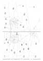
도 1은 본 발명에 따른 보온덮개 개폐장치를 갖춘 하우스형 식물공장의 정단면도,
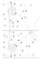
도 2는 도 1의 A부를 확대한 도면,
도 3은 도 1의 A부의 요부를 확대한 사시도,
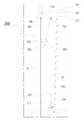
도 4는 도 1의 B부를 확대한 도면,
도 5는 본 발명의 작동 상태를 도시한 도면으로서, 도 2에 대한 대응도,
도 6 및 도 7은 본 발명의 작동 상태를 도시한 도면으로서, 도 1에 대한 대응도,
도 8은 도 7의 C부를 확대한 도면,
도 9는 본 발명의 작동 상태를 도시한 도면으로서, 도 8에 대한 대응도이다.1 is a front cross-sectional view of a house-type plant factory equipped with a thermal insulation cover opening and closing device according to the present invention,
2 is an enlarged view of part A of FIG. 1;
3 is an enlarged perspective view of a main part of part A of FIG. 1;
4 is an enlarged view of part B of FIG. 1;
5 is a diagram showing an operating state of the present invention, a corresponding diagram for FIG. 2,
6 and 7 are views showing the operating state of the present invention, a corresponding diagram for FIG. 1,
8 is an enlarged view of part C of FIG. 7;
9 is a view showing an operating state of the present invention, a corresponding view to FIG.
이하 본 발명을 첨부된 도면에 의거하여 상세히 설명한다.Hereinafter, the present invention will be described in detail with reference to the accompanying drawings.
도 1에 도시된 실시예의 경우, 하우스형 식물공장(PF)의 뼈대를 이루는 하우스 골조(10) 내부에 본 발명에 따른 보온덮개 개폐장치(100)와, 보온스크린 개폐장치(200)가 설치된 구조를 이룬다.In the case of the embodiment shown in Fig. 1, a structure in which a thermal insulation cover opening and
상기 하우스 골조(10)는, 중간 기둥골조(11)의 양측으로 외측 둘레골조(12)가 배치되고, 외측 지붕골조(13)가 중간 기둥골조(11)와 외측 둘레골조(12)에 의해 떠받들어진 구조를 이룬다. 여기서 미설명부호 '13a'는 환기를 위한 개구부이고, 미설명부호 '14'는 별도의 개폐장치에 의해 개구부(13a)를 선택적으로 개폐하는 지붕 덮개이다. 이러한 하우스 골조(10)의 외면을 비닐로 덮어주면 비닐하우스가 된다.In the
본 발명에 따른 보온덮개 개폐장치(100)는, 도 1 내지 도 4에 도시된 바와 같이, 상기 하우스 골조(10)에 설치되는 보온덮개 지지부재(110)와, 보온덮개 지지부재(110)에 얹혀지는 보온덮개 권취롤(120), 펼쳐친 보온덮개 권취롤(120)을 말아감는 제1견인끈(150), 말아감긴 보온덮개 권취롤(120)을 펼치는 제2 및 제3견인끈(160, 170), 제1견인끈(150)과 제2견인끈(160)을 각각 순방향과 역방향으로 권취하는 보온덮개용 권취장치로 구성된다.Insulation cover opening and
상기 보온덮개 지지부재(110)의 한쪽 선단부는 중간 기둥골조(11)에 고정되고, 다른 한쪽 선단부는 외측 둘레골조(12)에 고정된다. 상기 보온덮개 지지부재(110)는 보온덮개 권취롤(120)를 안정적으로 지지할 수 있는 어떠한 것이어도 무방하지만, 본 실시예의 경우에는 유연성 좋고 인장강도가 우수하며 설치가 용이한 와이어로프를 적용하였다. 본 실시예의 경우, 상기 중간 기둥골조(11)에 제1고정부재(16a ; 도 2 및 도 3 참조)를 설치하고, 외측 둘레골조(12)에 제2고정부재(16b ; 도 4 참조)를 설치해서, 보온덮개 지지부재(110)의 중간 기둥골조 방향 선단부(111 ; 도 2 및 도 3 참조)는 제1고정부재(16a)에 결속 고정하고, 외측 둘레골조 방향 선단부(112 ; 도 4 참조))는 제2고정부재(16a)에 결속 고정하여, 와이어로프 소재의 제1고정부재(16a)가 팽팽하게 당겨진 상태에서 보온덮개 권취롤(120)이 안정적으로 얹혀지도록 하였다. 본 실시예에서와 같이, 상기 보온덮개 지지부재(110)를 와이어로프 소재로 적용하는 경우, 중간 기둥골조(11)를 중심으로 양쪽으로 펼쳐진 보온덮개 지지부재(110)를 하나의 단선 와이어로프로 적용하는 것이 바람직하다. 본 실시예의 경우, 상기 제1고정부재(16a) 및 제2고정부재(16b)로는 파이프 또는 봉 형태의 것을 적용하였지만, 보온덮개 지지부재(110)의 선단부를 중간 기둥골조(11)나 외측 둘레골조(12)에 고정할 수 있는 어떠한 것이어도 무방하다. 참고로, 상기 중간 기둥골조(11)를 파이프나 봉 형태의 지지대로 적용할 수도 있지만, 이러한 경우에는 설치가 번거롭고, 설비 비용이 비싸지는 단점이 있다.One end portion of the insulating
상기 보온덮개 권취롤(120)은, 보온덮개 권취축(121)과 보온덮개(122)로 구성된다. 상기 보온덮개(122)의 중간 기둥골조 방향 선단부(122a ; 도 2 및 도 3 참조)는 제3고정부재(16c)를 매개로 중간 기둥골조(11)에 고정되고, 보온덮개(122)의 보온덮개 권취축 방향 선단부(122b ; 도 8 참조)는 보온덮개 권취축(121)에 고정된다. 이러한 보온덮개 권취롤(120)은 상기 보온덮개 지지부재(110)에 얹혀진 상태에서, 중간 기둥골조(11) 방향으로 말아감기고, 외측 둘레골조(12) 방향으로 펼쳐진다. 상기 제3고정부재(16c)는 중간 기둥골조(11)에 설치되어 보온덮개(122)의 중간 기둥골조 방향 선단부(122a)를 고정할 수 있는 것이라면 어떠한 것이어도 무방하지만, 본 실시예와 같이 보온덮개(122)의 선단을 안정적 고르게 고정하기에 적합한 파이프 또는 봉 형태의 것을 적용하는 것이 바람직하다.The thermal insulation
상기 보온덮개용 권취장치는 도 2 및 도 3에 도시된 바와 같이, 중간 기둥골조(11)에 회전 가능하게 고정되는 제1권취축(130)과, 제1권취축(130)을 구동하는 제1구동장치(140)로 구성된다. 상기 제1권취축(130)은 파이프 또는 봉 형태의 것이 바람직하며, 제1구동장치(140)는 전동모터를 적용하였다. 상기 제1구동장치(140)의 설치 위치는 특정 위치에 한정될 필요는 없지만, 동력전달 손실을 줄이기 위해서는 제1권취축(130)에 인접한 중간 기둥골조(11)에 설치하는 것이 바람직하다.2 and 3, the winding device for the thermal insulation cover includes a
상기 제1견인끈(150)은 도 2 및 도 3에 도시된 바와 같이, 제1견인끈(150)의 중간 기둥골조 방향 선단부(151)는 중간 기둥골조(11)에 고정된 상태에서, 보온덮개 권취롤(120)의 외면을 감싸면서, 제1견인끈(150)의 제1권취축 방향 선단부(152)는 제1권취축(130)에 권취 고정되어, 펼쳐진 보온덮개 권취롤(120)을 중간 기둥골조(11) 방향으로 말아감는 기능을 수행한다. 본 실시예의 경우, 상기 제1견인끈(150)의 중간 기둥골조 방향 선단부(151)는 제3고정부재(16c)에 고정하였지만, 필요에 따라서는 이와는 별도의 고정부재를 매개로 중간 기둥골조(11)에 고정할 수도 있음은 물론이다.As shown in FIGS. 2 and 3, the
상기 제2견인끈(160)은 도 2 및 도 3에 도시된 바와 같이, 제2견인끈(160)의 제1권취축 방향 선단부(161)는 제1권취축(130)에 제1견인끈(150)의 역방향으로 권취 고정되고, 제2견인끈(160)의 보온덮개 권취축 방향 선단부(162 ; 도 8 참조)는 보온덮개 권취축(121)에 고정되며, 보온덮개(122)의 내면에 배치된 상태로 보온덮개(122)와 함께 권취되어, 말아감긴 보온덮개 권취롤(120)을 중간 기둥골조(11) 방향에서 들어올려서 외측 둘레골조(12) 방향으로 펼치는 기능을 수행한다.As shown in FIGS. 2 and 3, the
상기 제3견인끈(170)은 도 2 내지 도 4에 도시된 바와 같이, 제3견인끈(170)의 제1권취축 방향 선단부(171)는 제1권취축(130)에 제1견인끈(150)의 역방향으로 권취 고정된 상태에서, 외측 둘레골조(12)에 설치된 제1걸림부(17a)를 감싸면서, 다른 한쪽 선단부는 보온덮개 권취축(121)에 고정되고, 보온덮개(122)의 내면에 배치된 상태로 보온덮개(122)와 함께 권취되어, 보온덮개 권취롤(120)을 잡아당겨서 외측 둘레골조(12) 방향으로 펼치는 기능을 수행한다. 상기 제1걸림부(17a)는 제3견인끈(170)을 안내하면서 이탈을 방지할 수 있는 어떠한 것이어도 무방하지만, 제3견인끈(170)의 마찰 손상을 방지하고, 동작이 보다 원활하게 이루어지도록 하게 위해서는 로울러 소재를 적용하는 것이 바람직하다.As shown in Figs. 2 to 4, the
여기서, 상기 제1권취축(130)은 보온덮개 권취롤(120) 보다는 상부에 배치되어야 한다는 점에 주목할 필요가 있다. 이처럼 제1권취축(130)이 보온덮개 권취롤(120) 보다 상부에 위치되어야만, 제1권취축(130)에 권취되어진 제2견인끈(160)의 제1권취축 방향 선단부(161)를 권취했을 때, 제2견인끈(160)이 보온덮개 권취롤(120)을 들어올려서 외측 둘레골조(12) 방향으로 펼칠 수 있게 된다. 각 구성요서들 간의 구조 상으로, 상기 제1권취축(130)이 보온덮개 권취롤(120) 보다 높게 위치될 수록, 제2견인끈(160)이 보온덮개 권취롤(120)을 들어올려서 펼치기에 유리하게 된다.Here, it is worth noting that the first winding
한편, 본 실시예의 경우, 보온스크린 개폐장치(200)를 설치해서, 윗쪽 부분만 아니라, 외측 둘레부분도 보온스크린(212)에 의해서 보온처리되도록 하였다. 본 실시예에 따른 보온스크린 개폐장치(200)는, 봉 형태의 보온스크린 고정부재(211)와 보온스크린(212)으로 구성된 보온스크린 유닛(210)과, 제2권취축(220)과 제2구동장치(230)로 구성된 보온스크린용 권취장치, 및 한쪽 선단부(241)는 제2권취축(220)에 권취 고정되고, 다른 한쪽 선단부(242)는 보온스크린 고정부재(211)에 고정되는 제4견인끈(240)으로 구성된다. 이러한 보온스크린 개폐장치(200)는 이미 널리 공지되어 사용되고 있으므로 이에 대한 보다 상세한 설명은 생략하기로 한다.On the other hand, in the case of the present embodiment, by installing the thermal insulation screen opening and
다만, 도 4에 도시된 바와 같이, 상기 보온덮개 지지부재(110)의 외측 둘레골조 방향 선단부(112)를 보강 지지대(15)로 보강 지지하고, 제2걸림부(17b)를 보강 지지대(15)에 인접한 보온덮개 지지부재(110)에 설치한 후, 보온스크린 개폐장치(200)의 제4견인끈(240)이 제2걸림부(17b)를 감싸면서 걸쳐지도록 하면, 보온스크린 개폐장치(200)의 설치가 용이하게 된다. 참고로, 상기 보온스크린 개폐장치(200)의 하중이 제2걸림부(17b)를 통해서 보온덮개 지지부재(15)에 가해지더라도, 보온덮개 지지부재(110)의 외측 둘레골조 방향 선단부(112)가 보강 지지대(15)에 의해 안정적으로 지지되므로, 보온덮개 지지부재(15)가 보온스크린 개폐장치(200)의 하중에 의해서 하방향으로 처지거나 하는 일은 발생되지 않게 된다.However, as shown in Figure 4, the outer circumferential frame direction
상기 제2걸림부(17b)도 제1걸림부(17a)와 마찬가지로, 제4견인끈(240)을 안내하면서 이탈을 방지할 수 있는 어떠한 것이어도 무방하지만, 제4견인끈(240)의 마찰 손상을 방지하고, 동작이 보다 원활하게 이루어지도록 하게 위해서는 로울러 소재를 적용하는 것이 바람직하다.Like the first hooking
이하 첨부된 도면을 참조하여, 본 발명에 따른 보온덮개 개폐장치(100)의 작동 상태를 설명하면 다음과 같다.Hereinafter, referring to the accompanying drawings, a description of the operating state of the thermal insulation cover opening and
도 1 내지 도 4에 도시된 바와 같은 정지 상태에서, 상기 제1권취축(130)이 제1구동장치(140)에 의해 구동되어서 도 5에 도시된 바와 같이 반시계 방향으로 회전되면, 제1견인끈(150)의 제1권취축 방향 선단부(152)는 제1권취축(130)으로부터 풀려나오게 되므로, 보온덮개 권취롤(120)이 펼쳐지는 것을 제1견인끈(150)이 방해하지 않게 된다. 이와 동시에, 상기 제2견인끈(160)의 제1권취축 방향 선단부(161)는 제1권취축(130)에 감겨들어가게 되므로, 제2견인끈(160)이 당겨지면서 보온덮개 권취롤(120)을 중간 기둥골조(11) 방향에서 들어올리게 되고, 이로 인해서 보온덮개 권취롤(120)은 외측 둘레골조(12) 방향으로 펼쳐지게 된다. 또한, 상기 제3견인끈(170)의 제1권취축 방향 선단부(171)도 이와 동시에 제1권취축(130)에 감겨들어가게 되므로, 제3견인끈(170)이 당겨지면서 보온덮개 권취롤(120)을 잡아당기게 되고, 이로 인해서 보온덮개 권취롤(120)은 외측 둘레골조(12) 방향으로 펼쳐지게 된다.In the stopped state as shown in FIGS. 1 to 4, when the first winding
상기 제1권취축(130)이 연속적으로 반시계 방향으로 회전되면, 도 6에 도시된 바와 같이 보온덮개 권취롤(120)이 연속적으로 외측 둘레골조(12) 방향으로 펼쳐지면서 이동되어서, 도 7 및 도 8에 도시된 바와 같이 완전하게 펼쳐지게 된다. 상기 보온덮개 권취롤(120)이 목표한 위치까지 완전하게 펼쳐지면 제1구동장치(140)가 작동 정지되어서 제1권취축(130)의 반시계 방향 회전이 멈추게 된다.When the first winding
한편, 상기 보온스크린 개폐장치(200)를 구동해서 보온스크린(212)으로 외측 둘레부분을 차폐하면, 도 7 및 도 8에 도시된 바와 같이, 식물공장(PF)의 비닐 하우스 내부 공간이 1차 온실영역(S1)과 2차 온실영역(S2)으로 구분되어진다.On the other hand, when the thermal insulation screen opening and
상기 2차 온실영역(S2)은 보온재질의 보온덮개(122)와 보온스크린(212)에 의해 2중으로 보온된 상태를 유지하게 되므로, 2차 온실영역(S2)에서 재배되는 농작물이 냉해 피해를 입지 않게 된다.Since the secondary greenhouse area (S2) is kept in a double-heated state by the
이후, 상기 제1구동장치(140)가 구동되어서 제1권취축(130)이 시계 방향으로 회전되면, 제1견인끈(150)의 제1권취축 방향 선단부(152)는 제1권취축(130)에 감겨들어가게 되므로, 도 9에 도시된 바와 같이, 제1견인끈(150)이 당겨지면서 보온덮개 권취롤(120)을 잡아당기게 되고, 이로 인해서 보온덮개 권취롤(120)은, 마치 김밥발로 김밥을 말 때 처럼, 중간 기둥골조(11) 방향으로 말아감기게 된다. 이와 동시에, 상기 제2견인끈(160)의 제1권취축 방향 선단부(161)와 제3견인끈(170)의 제1권취축 방향 선단부(171)는 각각 제1권취축(130)으로부터 풀려나오게 되고, 보온덮개(122)의 안쪽에 배치된 제2견인끈(160)과 제3견인끈(170)은 보온덮개(122)와 함게 보온덮개 권취축(121)에 말아감기게 된다. 도 9는 상기 제2견인끈(160)의 보온덮개 권취축 방향 선단부(162)와 제3견인끈(170)의 보온덮개 권취축 방향 선단부(172)가 보온덮개(122)의 보온덮개 권취축 방향 선단부(122b)와 함께 샌드위치 형태로 말아감기는 상태를 도시하고 있다.Thereafter, when the
상기 제1권취축(130)이 연속적으로 시계 방향으로 회전되면, 각각의 견인끈(150, 160, 170)과 보온덮개 권취롤(120)은, 도 6에 도시된 상태의 역방향으로 이동되면서, 도 1 내지 도 4에 도시된 바와 같은 초기 상태로 복귀된 후에 작동 정지되어, 1차 온실영역(S1)과 2차 온실영역(S2)이 상호 개방되어서 하나의 공간을 이루게 된다.When the first winding
본 발명에 따른 보온덮개 개폐장치(100)는 별도로 설명되지는 않았지만, 2중 보온 목적 이외에도 일조량 조절이나 기타 다른 목적을 위해서 사용될 수 있음은 물론이다.The thermal insulation cover opening and
이상 본 발명은 상기한 바와 같은 실시예에 한정되지 않고, 필요에 따라서 다양하게 변형 실시될 수 있다.The present invention is not limited to the above-described embodiments, and various modifications may be made as necessary.
일예로 본 실시예의 경우, 상기 보온덮개 권취롤(120)을 감는 수단으로 제2견인끈(160)과 제3견인끈(170)을 모두 사용하고 있지만, 필요에 따라서는 이들 중 어느 하나만을 이용할 수도 있다.As an example, in the case of the present embodiment, both the second pulling
또한, 본 실시예의 경우, 상기 보온덮개 지지부재(110)를 설치함에 있어서 중간 기둥골조 방향 선단부(111)를 외측 둘레골조 방향 선단부(112)보다 높게 형성하여 경사지도록 하였지만, 보온덮개 지지부재(110)의 경사각은 필요에 따라서 다양하게 변경될 수 있음은 물론이다.In addition, in the case of the present embodiment, in the installation of the thermal insulation
10 ; 하우스 골조,11 ; 중간 기둥골조,
12 ; 외측 둘레골조.13 ; 외측 지붕골조,
13a ; 개구부,14 ; 지붕 덮개,
15 ; 보강 지지대,16a ; 제1고정부재,
16b ; 제2고정부재,16c ; 제3고정부재,
17a ; 제1걸림부,17b ; 제2걸림부,
100 ; 보온덮개 개폐장치,110 ; 보온덮개 지지부재,
111 ; 중간 기둥골조 방향 선단부,112 ; 외측 둘레골조 방향 선단부,
120 ; 보온덮개 권취롤,121 ; 보온덮개 권취축,
122 ; 보온덮개,122a ; 중간 기둥골조 방향 선단부,
122b ; 보온덮개 권취축 방향 선단부,130 ; 제1권취축,
140 ; 제1구동장치,150 ; 제1견인끈,
151 ; 중간 기둥골조 방향 선단부,152 ; 제1권취축 방향 선단부,
160 ; 제2견인끈,161 ; 제1권취축 방향 선단부,
162 ; 보온덮개 권취축 방향 선단부,170 ; 제3견인끈,
171 ; 제1권취축 방향 선단부,172 ; 보온덮개 권취축 방향 선단부,
200 ; 보온스크린 개폐장치,210 ; 보온스크린 유닛,
211 ; 보온스크린 고정부재,212 ; 보온스크린,
220 ; 제2권취축,230 ; 제2구동장치,
240 ; 제4견인끈,241 ; 제2권취축 방향 선단부,
242 ; 보온스크린 고정부재 방향 선단부,
PF ; 식물공장,S1 : 1차 온실영역,
S2 ; 2차 온실영역.10; House frame, 11; Middle pillar frame,
12; Outer circumference frame. 13; Outer roof frame,
13a; Opening, 14; Roof covering,
15; Reinforcing support, 16a; The first fixed government goods,
16b; Second fixed government goods, 16c; The third fixed government goods,
17a; 1st catching part, 17b; 2nd jamming part,
100; Thermal insulation cover opening and closing device, 110; Insulation cover support member,
111; The front end portion in the direction of the intermediate pillar frame, 112; The tip of the outer circumferential frame,
120; Insulation cover winding roll, 121; Insulation cover winding shaft,
122; Insulation cover, 122a; The front end of the middle pillar frame,
122b; The tip of the thermal insulation cover in the winding axis direction, 130; 1st winding rewind,
140; A
151; The front end portion in the direction of the intermediate pillar frame, 152; The tip of the first winding axis direction,
160; 2nd pulling string, 161; The tip of the first winding axis direction,
162; The front end of the thermal insulation cover in the winding axis direction, 170; 3rd traction string,
171; A front end portion in the first winding axis direction, 172; The tip of the insulation cover in the winding axis direction,
200; Insulation screen opening and closing device, 210; Insulation screen unit,
211; Insulation screen fixing member, 212; Insulation screen,
220; Second winding shaft, 230; Second driving device,
240; 4th towing string, 241; The tip of the second winding axis direction,
242; Insulation screen fixing member direction tip,
PF; Plant factory, S1: primary greenhouse area,
S2; Second greenhouse area.
Claims (6)
Translated fromKorean보온덮개 권취축과, 한쪽 선단부는 보온덮개 권취축에 고정되고 다른 한쪽 선단부는 중간 기둥골조에 고정되는 보온덮개로 구성되어, 보온덮개 지지부재에 얹혀진 상태에서, 중간 기둥골조 방향으로 말아감기거나, 외측 둘레골조 방향으로 펼쳐지는 보온덮개 권취롤과 ;
중간 기둥골조에 회전 가능하게 고정되되, 보온덮개 권취롤 보다는 상부에 배치되는 제1권취축과 ;
제1권취축을 구동하는 제1구동장치와 ;
한쪽 선단부는 중간 기둥골조에 고정된 상태에서, 보온덮개 권취롤의 외면을 감싸면서, 다른 한쪽 선단부는 제1권취축에 권취 고정되어, 펼쳐진 보온덮개 권취롤을 중간 기둥골조 방향으로 말아감는 제1견인끈과 ;
한쪽 선단부는 제1권취축에 제1견인끈의 역방향으로 권취 고정되고, 다른 한쪽 선단부는 보온덮개 권취축에 고정되며, 보온덮개의 내면에 배치된 상태로 보온덮개와 함께 권취되어, 말아감긴 보온덮개 권취롤을 중간 기둥골조 방향에서 들어올려서 외측 둘레골조 방향으로 펼치는 제2견인끈을 포함하는 하우스형 식물공장의 보온덮개 개폐장치.
One end portion is fixed to the intermediate pillar frame, and the other end portion is fixed to the outer peripheral frame and a thermal insulation cover support member;
It is composed of a thermal insulation cover winding shaft, one end of which is fixed to the thermal insulation cover winding axis, and the other end of a thermal insulation cover fixed to the intermediate pillar frame, and is rolled up in the direction of the intermediate pillar frame while resting on the thermal insulation cover support member, Insulation cover winding roll spreading in the outer circumferential frame direction;
A first winding shaft which is rotatably fixed to the intermediate pillar frame and is disposed above the thermal insulation cover winding roll;
A first driving device for driving the first winding shaft;
One end is fixed to the middle pillar frame, while the outer surface of the heat insulating cover winding roll is wrapped, and the other end is wound and fixed to the first winding shaft, and the unfolded insulating cover winding roll is rolled in the direction of the intermediate pillar frame. Traction strap;
One end is wound and fixed to the first winding shaft in the reverse direction of the first pulling string, and the other end is fixed to the winding shaft of the thermal insulation cover, and it is wound together with the thermal insulation cover in a state disposed on the inner surface of the thermal insulation cover. A thermal insulation cover opening and closing device of a house-type plant factory comprising a second pulling string that lifts the cover winding roll in the direction of the middle pillar frame and spreads it in the direction of the outer peripheral frame.
The method according to claim 1, wherein one end of the first winding shaft is wound and fixed in a reverse direction of the first pulling string, and the other end is fixed to the thermal insulation cover winding shaft while enclosing the first engaging portion installed on the outer circumferential frame. , The thermal insulation cover opening and closing device of a house-type plant factory including a third pulling string that is arranged on the inner surface of the thermal insulation cover and is wound with the thermal insulation cover, and extends in the direction of the outer circumferential frame by pulling the insulation cover winding roll.
[3] The apparatus of claim 1 or 2, wherein the insulation cover support member is a wire rope.
[3] The apparatus of claim 2, wherein the first locking part is a roller.
The insulation cover support member according to claim 1 or 2, wherein a second engaging portion for installing the insulation screen opening/closing device is adjacent to the reinforcing support in a state where the front end of the insulation cover support member in the direction of the outer circumferential frame is supported by the reinforcing support. Insulation cover opening and closing device of a house-type plant factory, characterized in that the reinforcement is provided in.
[6] The apparatus of claim 5, wherein the second locking part is a roller.
Priority Applications (1)
| Application Number | Priority Date | Filing Date | Title |
|---|---|---|---|
| KR1020190150435AKR102158940B1 (en) | 2019-11-21 | 2019-11-21 | Thermal insulation cover device of plant factory type house |
Applications Claiming Priority (1)
| Application Number | Priority Date | Filing Date | Title |
|---|---|---|---|
| KR1020190150435AKR102158940B1 (en) | 2019-11-21 | 2019-11-21 | Thermal insulation cover device of plant factory type house |
Publications (1)
| Publication Number | Publication Date |
|---|---|
| KR102158940B1true KR102158940B1 (en) | 2020-09-22 |
Family
ID=72706962
Family Applications (1)
| Application Number | Title | Priority Date | Filing Date |
|---|---|---|---|
| KR1020190150435AActiveKR102158940B1 (en) | 2019-11-21 | 2019-11-21 | Thermal insulation cover device of plant factory type house |
Country Status (1)
| Country | Link |
|---|---|
| KR (1) | KR102158940B1 (en) |
Citations (7)
| Publication number | Priority date | Publication date | Assignee | Title |
|---|---|---|---|---|
| KR830000740B1 (en)* | 1978-08-04 | 1983-04-08 | 오오데 다까요시 | Open-close device for curtain of green-house |
| KR0116189Y1 (en)* | 1994-10-25 | 1998-04-17 | 이정호 | Opening and closing apparatus for the cover in vinyl house |
| KR20050095203A (en)* | 2004-03-25 | 2005-09-29 | 대한민국(관리부서:농촌진흥청) | Automatic pull and roll multi layer vertical screen system for green house |
| KR20130052336A (en)* | 2011-11-11 | 2013-05-22 | 주식회사 탑이엔지 | Device of opening shutting a vinyl plastic hothouseheat insulation covers |
| KR20130055065A (en)* | 2011-11-18 | 2013-05-28 | 주식회사 이안 | Inner-roof cover installing structure of vinyl house |
| KR20180061648A (en)* | 2016-11-30 | 2018-06-08 | 연재득 | Heat insulation apparatus for a vinyl house |
| KR101927620B1 (en) | 2017-05-25 | 2018-12-10 | 김종화 | Plant factory type Greenhouse |
- 2019
- 2019-11-21KRKR1020190150435Apatent/KR102158940B1/enactiveActive
Patent Citations (7)
| Publication number | Priority date | Publication date | Assignee | Title |
|---|---|---|---|---|
| KR830000740B1 (en)* | 1978-08-04 | 1983-04-08 | 오오데 다까요시 | Open-close device for curtain of green-house |
| KR0116189Y1 (en)* | 1994-10-25 | 1998-04-17 | 이정호 | Opening and closing apparatus for the cover in vinyl house |
| KR20050095203A (en)* | 2004-03-25 | 2005-09-29 | 대한민국(관리부서:농촌진흥청) | Automatic pull and roll multi layer vertical screen system for green house |
| KR20130052336A (en)* | 2011-11-11 | 2013-05-22 | 주식회사 탑이엔지 | Device of opening shutting a vinyl plastic hothouseheat insulation covers |
| KR20130055065A (en)* | 2011-11-18 | 2013-05-28 | 주식회사 이안 | Inner-roof cover installing structure of vinyl house |
| KR20180061648A (en)* | 2016-11-30 | 2018-06-08 | 연재득 | Heat insulation apparatus for a vinyl house |
| KR101927620B1 (en) | 2017-05-25 | 2018-12-10 | 김종화 | Plant factory type Greenhouse |
Similar Documents
| Publication | Publication Date | Title |
|---|---|---|
| US5520236A (en) | Greenhouse curtain system | |
| US4387533A (en) | Method and apparatus for retaining heat in greenhouse and similar structures | |
| US6843019B2 (en) | Horticultural greenhouse with removable cover | |
| EP0929725A1 (en) | Covering mechanism for a greenhouse | |
| KR101762976B1 (en) | Winding device for covering wall openings or windows | |
| CN110629920B (en) | Portable steel house room | |
| JP3268297B2 (en) | Seat opening and closing device | |
| KR102158940B1 (en) | Thermal insulation cover device of plant factory type house | |
| KR20130047784A (en) | Vinyl greenhouse having warm curtain | |
| JP4234148B2 (en) | Units used for construction of agricultural and horticultural houses | |
| RU2563764C2 (en) | Winding device for stopping of holes in walls | |
| KR101830570B1 (en) | Foldable awning apparatus for wide area | |
| KR200482821Y1 (en) | electromotion type roll blind with tension device | |
| KR200200073Y1 (en) | A open and close structure of vinyl for green house | |
| JP2018093855A (en) | Tunnel curtain apparatus for cultivation | |
| KR101853356B1 (en) | Truss structure with openable awning | |
| CN106105900A (en) | A kind of greenhouse rolling blind device | |
| KR20160144089A (en) | Ventilation method of vinyl house and appartus thereof | |
| KR100515895B1 (en) | Lag opening and closing system for vinyl plastic hothouse | |
| JP4620080B2 (en) | Opening and closing mechanism of the greenhouse | |
| KR200238774Y1 (en) | Inner lag opening and closing system for vinyl plastic hothouse | |
| US11129342B2 (en) | Light-deprivation system | |
| JP6576700B2 (en) | vinyl house | |
| KR100401804B1 (en) | Device of opening shutting a vinyl plastic hothouse heat insulation covers | |
| CN204782659U (en) | Novel curtain covering or awning on a car, boat, etc. outside window device |
Legal Events
| Date | Code | Title | Description |
|---|---|---|---|
| PA0109 | Patent application | Patent event code:PA01091R01D Comment text:Patent Application Patent event date:20191121 | |
| PA0201 | Request for examination | ||
| PA0302 | Request for accelerated examination | Patent event date:20191205 Patent event code:PA03022R01D Comment text:Request for Accelerated Examination Patent event date:20191121 Patent event code:PA03021R01I Comment text:Patent Application | |
| PE0902 | Notice of grounds for rejection | Comment text:Notification of reason for refusal Patent event date:20200330 Patent event code:PE09021S01D | |
| AMND | Amendment | ||
| PE0601 | Decision on rejection of patent | Patent event date:20200702 Comment text:Decision to Refuse Application Patent event code:PE06012S01D Patent event date:20200330 Comment text:Notification of reason for refusal Patent event code:PE06011S01I | |
| X091 | Application refused [patent] | ||
| AMND | Amendment | ||
| PX0901 | Re-examination | Patent event code:PX09011S01I Patent event date:20200702 Comment text:Decision to Refuse Application Patent event code:PX09012R01I Patent event date:20200514 Comment text:Amendment to Specification, etc. | |
| PX0701 | Decision of registration after re-examination | Patent event date:20200807 Comment text:Decision to Grant Registration Patent event code:PX07013S01D Patent event date:20200724 Comment text:Amendment to Specification, etc. Patent event code:PX07012R01I Patent event date:20200702 Comment text:Decision to Refuse Application Patent event code:PX07011S01I Patent event date:20200514 Comment text:Amendment to Specification, etc. Patent event code:PX07012R01I | |
| X701 | Decision to grant (after re-examination) | ||
| GRNT | Written decision to grant | ||
| PR0701 | Registration of establishment | Comment text:Registration of Establishment Patent event date:20200916 Patent event code:PR07011E01D | |
| PR1002 | Payment of registration fee | Payment date:20200916 End annual number:3 Start annual number:1 | |
| PG1601 | Publication of registration | ||
| PR1001 | Payment of annual fee | Payment date:20231018 Start annual number:4 End annual number:4 | |
| PR1001 | Payment of annual fee | Payment date:20240725 Start annual number:5 End annual number:5 |