KR102158232B1 - Apparatus for treating substrate and the methode thereof - Google Patents
Apparatus for treating substrate and the methode thereofDownload PDFInfo
- Publication number
- KR102158232B1 KR102158232B1KR1020170083601AKR20170083601AKR102158232B1KR 102158232 B1KR102158232 B1KR 102158232B1KR 1020170083601 AKR1020170083601 AKR 1020170083601AKR 20170083601 AKR20170083601 AKR 20170083601AKR 102158232 B1KR102158232 B1KR 102158232B1
- Authority
- KR
- South Korea
- Prior art keywords
- chamber
- pressure
- vent line
- substrate processing
- fluid
- Prior art date
- Legal status (The legal status is an assumption and is not a legal conclusion. Google has not performed a legal analysis and makes no representation as to the accuracy of the status listed.)
- Active
Links
Images


Classifications
- H—ELECTRICITY
- H01—ELECTRIC ELEMENTS
- H01L—SEMICONDUCTOR DEVICES NOT COVERED BY CLASS H10
- H01L21/00—Processes or apparatus adapted for the manufacture or treatment of semiconductor or solid state devices or of parts thereof
- H01L21/67—Apparatus specially adapted for handling semiconductor or electric solid state devices during manufacture or treatment thereof; Apparatus specially adapted for handling wafers during manufacture or treatment of semiconductor or electric solid state devices or components ; Apparatus not specifically provided for elsewhere
- H01L21/67005—Apparatus not specifically provided for elsewhere
- H01L21/67011—Apparatus for manufacture or treatment
- H01L21/67017—Apparatus for fluid treatment
- H—ELECTRICITY
- H01—ELECTRIC ELEMENTS
- H01L—SEMICONDUCTOR DEVICES NOT COVERED BY CLASS H10
- H01L21/00—Processes or apparatus adapted for the manufacture or treatment of semiconductor or solid state devices or of parts thereof
- H01L21/02—Manufacture or treatment of semiconductor devices or of parts thereof
- H01L21/02041—Cleaning
- H—ELECTRICITY
- H01—ELECTRIC ELEMENTS
- H01L—SEMICONDUCTOR DEVICES NOT COVERED BY CLASS H10
- H01L21/00—Processes or apparatus adapted for the manufacture or treatment of semiconductor or solid state devices or of parts thereof
- H01L21/67—Apparatus specially adapted for handling semiconductor or electric solid state devices during manufacture or treatment thereof; Apparatus specially adapted for handling wafers during manufacture or treatment of semiconductor or electric solid state devices or components ; Apparatus not specifically provided for elsewhere
- H01L21/67005—Apparatus not specifically provided for elsewhere
- H01L21/67242—Apparatus for monitoring, sorting or marking
Landscapes
- Engineering & Computer Science (AREA)
- Physics & Mathematics (AREA)
- Condensed Matter Physics & Semiconductors (AREA)
- General Physics & Mathematics (AREA)
- Manufacturing & Machinery (AREA)
- Computer Hardware Design (AREA)
- Microelectronics & Electronic Packaging (AREA)
- Power Engineering (AREA)
- Cleaning Or Drying Semiconductors (AREA)
Abstract
Translated fromKoreanDescription
Translated fromKorean본 발명은 기판 처리 장치 및 기판 처리 방법에 관한 것으로서, 더욱 상세하게는 기판을 수용하여 처리하는 챔버 내부의 압력을 조절하여 안정적인 유체 배출을 진행하기 위한 기판 처리 장치 및 기판 처리 방법에 관한 것이다.The present invention relates to a substrate processing apparatus and a substrate processing method, and more particularly, to a substrate processing apparatus and a substrate processing method for stably discharging a fluid by controlling a pressure inside a chamber that receives and processes a substrate.
물질은 임계점(supercritical point)이라고 불리는 일정한 고온·고압의 한계를 넘으면 기체와 액체의 구별을 할 수 없는 상태인 임계상태가 되는데, 이 상태에 있는 물질을 초임계유체라고 한다.When a substance exceeds the limit of a certain high temperature and high pressure called a supercritical point, it becomes a critical state, a state in which gas and liquid cannot be distinguished. A substance in this state is called a supercritical fluid.
초임계유체는 분자의 밀도 변화가 큰 특징을 가진다. 분자의 밀도는 액체에 가깝지만, 점성도는 낮아 기체에 가깝기 때문이다. 또 기체처럼 확산이 빨라 열전도성이 물만큼이나 높지만, 액체처럼 용매로 사용되어 용질 주변의 용매 농도가 극히 높아지는 특이한 성질을 가지고 있고, 표면장력의 영향을 받지 않는다. 따라서 초임계 유체는 화학반응에 아주 유용하며 혼합물에서 특정 성분을 추출·분리하는 성질이 강해 여러 분야에서 활용되고 있고, 특히 임계온도가 상온에 비교적 가까우며 비극성 물질인 초임계 이산화탄소의 활용도가 높다.Supercritical fluids are characterized by a large change in molecular density. This is because the molecular density is close to that of a liquid, but its viscosity is low and close to that of gas. In addition, the thermal conductivity is as high as water because it diffuses quickly like a gas, but it is used as a solvent like a liquid, so it has a unique property that the concentration of the solvent around the solute is extremely high, and is not affected by surface tension. Therefore, supercritical fluids are very useful for chemical reactions and are used in various fields due to their strong properties of extracting and separating specific components from mixtures. In particular, the critical temperature is relatively close to room temperature, and the utilization of supercritical carbon dioxide, a non-polar material, is high.
반도체 소자를 제조하기 위한 다양한 단위공정에서도 초임계 유체가 다방면으로 활용된다. 특히, 최근 반도체 소자의 디자인 룰(design rule)이 지속적으로 감소하여 미세구조 패턴이 주를 이루면서 패턴의 종횡비(Aspect Ratio)가 급격히 증가하고 있어, 식각공정이나 세정공정과 같은 습식 공정이 완료된 후 약액을 건조하는 과정에서 발생하는 패턴 무너짐(Pattern leaning) 현상의 해결 방법으로 초임계 유체가 이용되고 있다.In various unit processes for manufacturing semiconductor devices, supercritical fluids are used in various ways. In particular, as the design rules of semiconductor devices continue to decrease in recent years, the aspect ratio of the pattern is rapidly increasing as the microstructure pattern is predominantly, so after the wet process such as etching or cleaning is completed A supercritical fluid is used as a solution to the pattern leaning phenomenon that occurs during the drying process.
도 1을 참조하여 상기 패턴 무너짐 현상을 설명한다.The pattern collapse phenomenon will be described with reference to FIG. 1.
패턴 무너짐 현상은, 패턴(P)이 형성된 기판(W) 상에 약액(C)이 공급되고(1-1), 공급된 약액(C)이 건조되는 과정에서 패턴(P) 사이사이에 불규칙하게 잔존하는 약액의 표면장력으로 인한 라플라스 압력(Laplace Pressure)이 발생하여(1-2), 패턴(P)간에 브리지(B)가 형성되고(1-3), 공급된 약액(C)이 모두 건조되어도 패턴(P) 간의 흡착력(Adhesive Energy)으로 인해 복원되지 않은 채 패턴(P)이 붕괴되는(1-4) 공정 불량 현상이다.The pattern collapse phenomenon is irregularly between the patterns P in the process of supplying the chemical solution C on the substrate W on which the pattern P is formed (1-1) and drying the supplied chemical solution C. Laplace pressure occurs due to the surface tension of the remaining chemical solution (1-2), a bridge (B) is formed between the patterns (P) (1-3), and all the supplied chemical solution (C) is dried. This is a process failure phenomenon in which the pattern P collapses (1-4) without being restored due to the adhesive energy between the patterns P.
초임계 유체는 세정과 린스 공정을 거친 기판상에 공급되어 패턴 무너짐 현상이 일어나기 전에 기판을 빠르게 건조시키는 역할을 하며 초임계 이산화탄소가 주로 사용된다. 린스액으로는 순수(DI)가 주로 사용되는데, 초임계 이산화탄소는 비극성 물질이므로 극성 물질인 순수와 반응하지 않는다.The supercritical fluid is supplied onto the substrate that has undergone a cleaning and rinsing process to quickly dry the substrate before pattern collapse occurs, and supercritical carbon dioxide is mainly used. Pure water (DI) is mainly used as a rinse solution, and since supercritical carbon dioxide is a non-polar substance, it does not react with pure water, a polar substance.
상기 초임계 이산화탄소와의 반응을 촉진시키기 위하여, 이소프로필알코올(IPA)을 기판 상에 공급하여 순수를 이소프로필알코올(IPA)로 치환시킨다. 즉, 기판상에 공급되는 초임계 이산화탄소는 이소프로필알코올과 반응하여 초임계 혼합물을 이루고 기판으로부터 분리되어 빠른 속도로 기판을 건조한다.In order to promote the reaction with the supercritical carbon dioxide, isopropyl alcohol (IPA) is supplied on the substrate to replace pure water with isopropyl alcohol (IPA). That is, the supercritical carbon dioxide supplied to the substrate reacts with isopropyl alcohol to form a supercritical mixture, and is separated from the substrate to dry the substrate at a high speed.
초임계 유체를 지속적으로 공급하며 기판을 건조하면, 챔버 내부의 초임계 혼합물의 농도가 점점 높아지며 고압 상태가 되므로, 챔버 내부의 압력을 낮추기 위해 부분적인 초임계 혼합물의 배출이 반복적으로 진행되고, 이후 건조공정을 마친 후에는 챔버 내부의 초임계 혼합물을 완전히 배출시키는 단계가 수행된다.If the substrate is dried while continuously supplying the supercritical fluid, the concentration of the supercritical mixture inside the chamber increases gradually and becomes a high pressure state, so that partial supercritical mixture is repeatedly discharged to lower the pressure inside the chamber. After completing the drying process, a step of completely discharging the supercritical mixture inside the chamber is performed.
챔버 내부의 초임계 혼합물의 배출은 벤트라인(Vent Line)을 통해 이루어지는데, 고온 고압의 챔버 내부로부터 초임계 혼합물이 배출되면서 압력의 변화가 심해 상변화와 빙결 등의 문제가 발생할 수 있으므로 이를 방지하기 위한 단계적인 감압장치와 감압방법이 필요하다.Discharge of the supercritical mixture inside the chamber is done through a vent line. As the supercritical mixture is discharged from the inside of the high-temperature and high-pressure chamber, the pressure changes severely, so problems such as phase change and freezing may occur. Step-by-step decompression device and decompression method are required
상기 단계적인 감압장치와 감압방법이 나타난 종래 기술은 대한민국 등록특허 제10-1074460호에 개시되어 있다.The prior art in which the step-by-step depressurization device and decompression method are shown is disclosed in Korean Patent No. 10-1074460.
본 발명은 상기와 같은 종래 기술을 보완하기 위하여 안출된 것으로서, 기판 처리 공정이 완료되고 챔버 외부로 배출되는 유체의 압력을 조절하여 안정적인 유체 배출을 진행하기 위한 기판 처리 장치 및 기판 처리 방법을 제공함에 그 목적이 있다.The present invention was devised to supplement the prior art as described above, and provides a substrate processing apparatus and a substrate processing method for stable fluid discharge by controlling the pressure of the fluid discharged to the outside of the chamber after the substrate processing process is completed. There is a purpose.
또한, 기판을 수용하여 처리하는 챔버 내부의 압력을 유지하여 상변화에 의한 챔버 내부의 오염을 방지하고자 함에 그 목적이 있다.In addition, the purpose is to prevent contamination of the chamber due to phase change by maintaining the pressure inside the chamber receiving and processing the substrate.
상술한 바와 같은 목적을 구현하기 위한 본 발명은, 기판을 수용하여 처리하는 챔버에 연결되어 상기 챔버 내부의 유체를 배출하는 벤트라인과, 상기 벤트라인에 구비되어 상기 챔버 내부의 압력을 단계적으로 감압하는 압력조정부를 포함하여 구성된다.The present invention for realizing the above object is a vent line connected to a chamber that receives and processes a substrate to discharge the fluid inside the chamber, and a vent line provided in the vent line to stepwise reduce the pressure inside the chamber. It is configured to include a pressure adjustment unit.
상기 압력조정부는 상기 챔버 내부의 압력을 측정하는 압력감지부와 상기 벤트라인의 개폐를 조절하는 제어부를 포함하여 구성되며, 상기 챔버 내부의 압력을 단계적으로 감압하는 역할을 하도록 한다.The pressure adjusting unit includes a pressure sensing unit that measures the pressure inside the chamber and a control unit that controls opening and closing of the vent line, and serves to step down the pressure inside the chamber.
상기 압력조정부에는 레귤레이터가 더 포함되어, 상기 제어부가 상기 레귤레이터를 제어함으로써 상기 벤트라인의 개폐를 조절한다.The pressure adjusting unit further includes a regulator, and the control unit controls the regulator to control opening and closing of the vent line.
또한, 상기 벤트라인은, 기판 처리 공정 중 상기 챔버 내부로부터 배출되는 유체를 제어하는 벤트라인과, 기판 처리 공정이 완료된 후 상기 챔버 내부로부터 배출되는 유체를 제어하는 벤트라인으로 나누어 구성될 수 있다.In addition, the vent line may be divided into a vent line for controlling fluid discharged from the chamber during a substrate processing process and a vent line for controlling fluid discharged from the chamber after the substrate processing process is completed.
전자는 상기 챔버 내부의 압력을 적절하게 유지하는 기능을 하고, 후자는 상기 챔버 내부 압력을 단계적으로 감압시키는 기능을 한다.The former functions to properly maintain the pressure inside the chamber, and the latter functions to step down the pressure inside the chamber.
또한, 기판 처리 공정이 완료된 후 상기 챔버에 불활성 가스를 공급하여 상기 챔버 내부의 잔존 유체의 상변화를 방지할 수 있고, 상기 불활성 가스는 상기 챔버가 개방된 후에도 공급되어 상기 챔버 내부의 오염을 예방할 수 있다.In addition, after the substrate processing process is completed, an inert gas is supplied to the chamber to prevent a phase change of the residual fluid in the chamber, and the inert gas is supplied even after the chamber is opened to prevent contamination inside the chamber. I can.
본 발명에 따른 기판 처리 장치 및 기판 처리 방법에 의하면, 기판 처리 공정이 완료되고 챔버 외부로 배출되는 유체의 압력을 조절하여 유체를 안정적으로 배출할 수 있다.According to the substrate processing apparatus and the substrate processing method according to the present invention, the fluid can be stably discharged by controlling the pressure of the fluid discharged to the outside of the chamber after the substrate processing process is completed.
또한, 기판을 수용하여 처리하는 챔버 내부의 압력을 유지하여 상변화에 의한 챔버 내부의 오염을 방지할 수 있다.In addition, it is possible to prevent contamination of the interior of the chamber due to a phase change by maintaining the pressure inside the chamber receiving and processing the substrate.
도 1은 기판 처리 공정에서 발생하는 패턴 무너짐 현상을 설명하기 위한 도면.
도 2는 본 발명에 의한 기판 처리 장치의 개략적인 구성도.
도 3은 본 발명에 의해 유체 배출 압력을 조절하는 네 개의 벤트라인을 구비한 기판 처리 장치의 개략적인 구성도.
도 4는 본 발명에 의해 불활성기체를 이용하는 기판 처리 장치의 개략적인 구성도.
도 5는 본 발명에 의한 기판 처리 방법의 순서도.1 is a diagram for describing a pattern collapse phenomenon occurring in a substrate processing process.
2 is a schematic configuration diagram of a substrate processing apparatus according to the present invention.
3 is a schematic configuration diagram of a substrate processing apparatus having four vent lines for controlling a fluid discharge pressure according to the present invention.
4 is a schematic configuration diagram of a substrate processing apparatus using an inert gas according to the present invention.
5 is a flowchart of a substrate processing method according to the present invention.
이하 첨부한 도면을 참조하여 본 발명의 바람직한 실시예에 대한 구성 및 작용을 상세히 설명하면 다음과 같다.Hereinafter, the configuration and operation of a preferred embodiment of the present invention will be described in detail with reference to the accompanying drawings.
본 발명의 일실시예에 의한 기판 처리 장치는, 도 2에 나타난 바와 같이, 기판(W)을 수용하여 처리하는 챔버(100)에 연결되어 상기 챔버(100) 내부의 유체를 배출하는 벤트라인(V)과, 상기 벤트라인(V)에 구비되어 상기 챔버(100) 내부의 압력을 단계적으로 조절하는 압력조정부(200)를 포함하여 구성된다.A substrate processing apparatus according to an embodiment of the present invention, as shown in FIG. 2, is connected to a
상기 압력조정부(200)는, 상기 챔버(100) 내부의 압력을 측정하는 압력감지부(210)와, 상기 밸브의 개폐를 조절하는 압력제어부(220)를 포함한다.The
상기 기판(W)은, 반도체 기판이 되는 실리콘 웨이퍼일 수 있다. 그러나 본 발명이 이에 한정되는 것은 아니며, 상기 기판(W)은 LCD(liquid crystal display), PDP(plasma display panel)와 같은 평판 디스플레이 장치용으로 사용하는 유리 등의 투명 기판일 수 있다. 또한, 상기 기판(W)은 형상 및 크기가 도면에 의해 한정되는 것은 아니며, 원형 및 사각형 플레이트 등 실질적으로 다양한 형상과 크기를 가질 수 있다.The substrate W may be a silicon wafer that becomes a semiconductor substrate. However, the present invention is not limited thereto, and the substrate W may be a transparent substrate such as glass used for a flat panel display device such as a liquid crystal display (LCD) or a plasma display panel (PDP). Further, the shape and size of the substrate W are not limited by the drawings, and may have substantially various shapes and sizes, such as circular and rectangular plates.
상기 기판(W)을 처리하는 기판 처리 공정에서, 상기 챔버(100)에 공급되는 공급유체는 초임계유체일 수 있다. 상기 초임계유체는 상기 기판(W)에 선 공급되는 약액의 종류에 대응하여 구비될 수 있다. 상기 기판(W)에 선 공급되는 약액으로는, 에틸글리콜(ethyl glycol), 1-프로파놀(propanol), 테트라하이드로프랑(tetrahydraulic franc), 4-하이드록시(hydroxyl), 4-메틸(methyl), 2-펜타논(pentanone), 1-부타놀(butanol), 2-부타놀, 메탄올(methanol), 에탄올(ethanol), 디메틸에틸(dimethylether), n-프로필알코올(n-propyl alcohol) 등이 있다. 이에 대응하여 상기 유기약액을 제거하기 위한 초임계유체는 초임계 이산화탄소(SCCO2), 물(H2O), 메탄(CH4), 에탄(C2H6), 프로판(C3H8), 에틸렌(C2H4), 프로필렌(C2H2), 메탄올(C2H3OH), 에탄올(C2H5OH), 육불화황(SF6), 아세톤(C3H8O) 등이 있다.In a substrate processing process of processing the substrate W, the supply fluid supplied to the
상기 압력감지부(210)는 상기 챔버(100) 내부의 압력을 측정하고, 압력 측정값을 상기 압력제어부(220)에 전달한다.The
상기 압력제어부(220)에는 기판 처리 공정 진행을 유지하기에 적절한 상기 챔버(100) 내부 압력이 설정되어, 상기 챔버(100) 내부에서 기판 처리 공정이 진행중인 경우, 상기 챔버(100) 내부의 압력이 상기 설정된 압력값을 유지하도록 상기 벤트라인(V)의 개폐를 제어한다.In the
또한, 기판 처리 공정이 완료된 경우, 상기 압력제어부(220)는 상기 챔버(100) 내부의 압력이 상압(atmospheric pressure)이 될 때까지 안정적인 감압이 이루어지도록 하고, 상기 챔버(100) 내부의 압력이 상압이 되면 상기 공정 완료 유체를 완전히 배출하도록 상기 벤트라인(V)의 개폐를 제어한다.In addition, when the substrate processing process is completed, the
상기 벤트라인(V)에는 밸브(240)가 더 구비되어 상기 벤트라인(V)의 개폐를 보조하는 역할을 하도록 할 수 있다.A
또한, 상기 벤트라인(V)에는 레귤레이터(230)가 더 구비될 수 있다.In addition, a
상기 압력제어부(220)는 상기 레귤레이터(230)에 연결되어, 상기 압력감지부(210)의 압력 측정값에 따라 상기 벤트라인(V)의 개폐 정도를 제어함으로써, 상기 벤트라인(V)을 통해 상기 챔버(100) 내부의 유체가 적절한 유량과 압력으로 배출되도록 한다.The
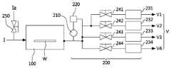
상기 벤트라인(V)은, 도 3에 나타난 바와 같이, 제1벤트라인(V1), 제2벤트라인(V2), 제3벤트라인(V3) 제4벤트라인(V4)으로 이루어질 수 있다.As shown in FIG. 3, the vent line V may include a first vent line V1, a second vent line V2, a third vent line V3, and a fourth vent line V4.
상기 제1벤트라인(V1)과 상기 제2벤트라인(V2)은, 각각 제1레귤레이터(231)와 제1밸브(241), 제2레귤레이터(232)와 제2밸브(242)를 포함하여 구성될 수 있으며, 상기 기판(W)의 처리 공정이 진행중인 챔버(100) 내부의 유체를 배출하여 상기 챔버(100) 내부의 압력을 유지하는 역할을 한다.The first vent line V1 and the second vent line V2 include a
상기 압력제어부(220)에는 상기 제1벤트라인(V1)의 압력 상한선과 압력 하한선이 입력되고, 상기 압력제어부(220)는 상기 제1레귤레이터(231)를 제어한다.The
상기 압력감지부(210)에서 측정되는 압력이 상기 압력 상한선까지 상승하면, 상기 제1밸브(241)가 열리고, 상기 챔버(100) 내부의 유체는 상기 제1레귤레이터(231)에 의해 개폐 정도가 조절된 제1벤트라인(V1)을 통해 배출된다.When the pressure measured by the
상기 압력감지부(210)에서 측정되는 압력이 상기 압력 하한선까지 떨어지면, 상기 제1밸브(241)가 닫혀 상기 챔버(100) 내부의 유체 배출이 중단된다. 이후, 상기 압력감지부(210)에서 측정되는 압력이 상기 압력 상한선에 도달할 때마다 상기 유체 배출 과정을 반복하여 상기 챔버(100)의 내부 압력을 유지한다.When the pressure measured by the
상기 챔버(100)에 대한 유체 공급은 상기 챔버(100) 내부의 유체 배출이 이루어지는 동안 중단될 수 있으며, 상기 압력감지부(210)에서 측정되는 압력이 상기 압력 하한선에 도달하면 다시 공급이 시작되도록 할 수 있다.The fluid supply to the
상기 압력제어부(220)에는 상기 제2벤트라인(V2)의 압력 상한선과 압력 하한선이 입력되어 상기 챔버(100) 내부의 유체 배출 과정이 수행된다.The pressure upper limit and lower pressure limit of the second vent line V2 are input to the
상기 제1벤트라인(V1)과 상기 제2벤트라인(V2)의 압력 상한선과 압력 하한선은 상이한 압력 범위로 설정되어, 경우에 따라 상기 제1벤트라인(V1) 또는 상기 제2벤트라인(V2) 중 하나를 선택하여 상기 챔버(100) 내부의 유체 배출이 진행되도록 할 수 있다.The pressure upper limit and the lower pressure limit of the first vent line V1 and the second vent line V2 are set to different pressure ranges, and in some cases, the first vent line V1 or the second vent line V2 ) May be selected so that the fluid inside the
또한, 상기 제1레귤레이터(231)와 상기 제2레귤레이터(232)의 배출 압력에 차등을 두어 경우에 따라 상기 제1벤트라인(V1) 또는 상기 제2벤트라인(V2) 중 하나를 선택하여 상기 챔버(100) 내부의 유체 배출이 진행되도록 할 수 있다.In addition, a difference is provided between the discharge pressures of the
상기 제3벤트라인(V3)과 상기 제4벤트라인(V4)은, 각각 제3레귤레이터(233)와 제3밸브(243), 제4레귤레이터(234)와 제4밸브(244)를 포함하여 구성될 수 있으며, 기판 처리 공정이 완료된 상기 챔버(100) 내부의 유체를 완전히 배출하는 역할을 한다.The third vent line V3 and the fourth vent line V4 include a
상기 챔버(100) 내부에서 상기 기판 처리 공정이 완료되면, 상기 제3밸브(243)가 열려 상기 챔버(100) 내부의 유체가 상기 제3레귤레이터(233)에 의해 조절된 압력으로 상기 제3벤트라인(V3)을 통해 배출된다. 상기 제3벤트라인(V3)은 상기 챔버(100) 내부의 압력이 상압이 될 때까지 상기 챔버(100) 내부의 유체를 소량씩 배출하며 점진적으로 감압시킨다.When the substrate processing process is completed in the
상기 챔버(100) 내부의 압력이 상압이 되면, 상기 제4밸브(244)가 열려 상기 챔버(100) 내부에 잔존하는 유체가 상기 제4레귤레이터(234)에 의해 조절된 배출 압력으로 상기 제2벤트라인(V4)을 통해 완전히 배출된다. 이때 상기 챔버(100) 내부와 외부의 압력차가 없으므로, 상기 제4벤트라인(V4)을 통과하는 유량과 배출 압력에 제한이 없을 수 있고, 상기 제4레귤레이터(234)는 상기 제4벤트라인(V4)의 구성에서 제외될 수 있다.When the pressure inside the
또한, 도 3에 나타난 바와 같이, 상기 챔버(100) 내부에 유체를 공급하는 공급라인(I)에는 불활성 가스를 공급하는 불활성 가스 공급라인(Ia)이 더 구비될 수 있다.In addition, as shown in FIG. 3, an inert gas supply line (Ia) for supplying an inert gas may be further provided in the supply line (I) for supplying a fluid into the
기판 처리 공정 완료 후, 상기 챔버(100) 내부의 유체가 배출되므로 상기 챔버(100) 내부의 압력이 급격하게 변화되고, 이때 상기 챔버(100) 내부의 잔존 유체가 상변화하여 상기 챔버(100) 내부를 오염시키는 현상이 발생할 수 있다.After the substrate processing process is completed, since the fluid inside the
이를 방지하기 위한 구성으로, 상기 불활성 가스는 기판 처리 공정 완료 후에 상기 챔버(100) 내부에 공급되며, 상기 챔버(100) 내부의 압력을 높임으로써 상기 잔존 유체의 상변화를 방지하고 상기 챔버(100) 내부의 오염을 최소화시키는 역할을 한다.In a configuration for preventing this, the inert gas is supplied into the
또한, 상기 불활성 가스는, 상기 잔존 유체가 모두 배출된 후 상기 챔버(100)를 개방하는 단계에서 상기 챔버(100) 내부에 공급되어 상기 챔버(100) 외부의 공기가 챔버(100) 내부로 유입되는 것을 차단함으로써, 상기 챔버(100) 외부의 공기가 상기 챔버(100) 내부를 오염시키는 것을 방지하는 역할을 한다.In addition, the inert gas is supplied into the
상기 불활성 가스 공급라인(Ia)는 상기 공급라인(I)에 연결되도록 구비될 수 있으며, 상기 불활성 가스의 출입을 제어하는 불활성 가스 밸브(250)를 포함하여 구비될 수 있다.The inert gas supply line (Ia) may be provided to be connected to the supply line (I), and may include an inert gas valve (250) for controlling the entrance of the inert gas.
상기 불활성 가스는 질소기체(N2)일 수 있다.The inert gas may be nitrogen gas (N2).
도 5를 참조하여 본 발명의 기판 처리 장치에 의한 기판 처리 방법에 대해 서술한다.A substrate processing method by the substrate processing apparatus of the present invention will be described with reference to FIG. 5.
단계 S10은, 기판을 수용하여 처리하는 챔버(100) 내부에서 기판 처리 공정이 수행되는 단계이다.Step S10 is a step in which a substrate processing process is performed inside the
초임계 유체를 이용하는 기판 처리 공정은 고압의 환경이 요구되므로, 공정이 진행될수록 상기 챔버(100) 내부의 압력이 높아지게 된다.Since the substrate processing process using the supercritical fluid requires a high pressure environment, the pressure inside the
단계 S20은, 기판 처리 공정이 진행중인 상기 챔버(100) 내부의 압력을 유지하며 벤트라인(V)을 통해 상기 챔버(100) 내부의 유체를 배출하는 단계이다.Step S20 is a step of discharging the fluid inside the
먼저, 압력감지부(210)에서 상기 챔버(100) 내부의 압력을 측정하고, 상기 측정값이 압력제어부(220)에 전달되면, 상기 압력제어부(220)가 상기 벤트라인(V)에 구비되는 레귤레이터(230)를 제어하여 상기 벤트라인(V)의 개폐 정도를 조절한다. 즉, 상기 챔버(100)로부터 배출되는 유체의 양과 압력을 조절한다.First, when the pressure inside the
상기 단계 S20은 기판 처리 공정이 진행되는 동안 반복해서 수행되어 상기 챔버(100) 내부의 압력이 적절하게 유지되도록 한다.The step S20 is repeatedly performed while the substrate processing process is in progress so that the pressure inside the
단계 S30은, 기판 처리 공정이 완료된 상기 챔버(100) 내부의 압력을 단계적으로 감압하며 상기 벤트라인(V)을 통해 상기 챔버(100) 내부의 유체를 배출하는 단계이다.Step S30 is a step of stepwise reducing the pressure inside the
기판 처리 공정이 완료되면, 압력제어부(220)가 벤트라인(V)에 구비되는 레귤레이터(230)의 개폐 정도를 조절하여 상기 챔버로부터 배출되는 유체의 양과 압력을 제어하고 상기 챔버(100) 내부의 압력이 상압까지 단계적으로 감압되도록 한다.When the substrate processing process is completed, the
상기 압력감지부(210)는 계속해서 상기 챔버(100) 내부의 압력을 측정하고 상기 압력제어부(220)에 전달하여 상기 챔버(100) 내부의 감압이 원활하게 이루어지도록 한다.The
상기 챔버(100) 내부의 압력이 상압이 되면, 상기 벤트라인(V)을 완전히 개방하여 상기 챔버(100) 내부의 유체를 완전히 배출한다.When the pressure inside the
상기 단계 S30에는, 상기 챔버(100)에 불활성 가스를 공급하는 단계가 더 포함된다.The step S30 further includes supplying an inert gas to the
상기 불활성 가스의 공급으로 상기 챔버(100) 내부의 압력이 유지되고, 상기 챔버(100) 내부에 잔존하는 상기 유체의 상변화가 방지되어, 상기 챔버(100) 내부의 오염을 최소화할 수 있다.By supplying the inert gas, the pressure inside the
단계 S40은, 상기 잔존 유체의 배출이 완료되어 열린 상기 챔버(100)에 불활성 가스를 공급하는 단계이다.Step S40 is a step of supplying an inert gas to the
상기 불활성 가스의 공급으로 상기 챔버(100) 외부의 공기가 상기 챔버(100) 내부에 유입되는 것을 차단시켜 상기 챔버(100) 내부의 오염을 방지할 수 있다.By supplying the inert gas, air outside the
이상 설명한 바와 같이, 본 발명은 상술한 실시예에 한정되지 아니하며, 청구범위에서 청구되는 본 발명의 기술적 사상에 벗어남 없이 당해 발명이 속하는 기술분야에서 통상의 지식을 가진 자에 의해 자명한 변형실시가 가능하며, 이러한 변형실시는 본 발명의 범위에 속한다.As described above, the present invention is not limited to the above-described embodiments, and modifications are apparent by those of ordinary skill in the art without departing from the technical spirit of the present invention claimed in the claims. It is possible, and such modifications are within the scope of the present invention.
W: 기판100: 챔버
200: 압력조정부210: 압력감지부
220: 압력제어부V: 벤트라인
V1: 제1벤트라인V2: 제2벤트라인
V3: 제3벤트라인V4: 제4벤트라인
230: 레귤레이터231: 제1레귤레이터
232: 제2레귤레이터233: 제3레귤레이터
234: 제4레귤레이터240: 밸브
241: 제1밸브242: 제2밸브
243: 제3밸브244: 제4밸브
I: 공급라인Ia: 불활성 가스 공급라인
250: 불활성 가스 밸브W: substrate 100: chamber
200: pressure adjusting unit 210: pressure sensing unit
220: pressure control unit V: vent line
V1: first vent line V2: second vent line
V3: third vent line V4: fourth vent line
230: regulator 231: first regulator
232: second regulator 233: third regulator
234: fourth regulator 240: valve
241: first valve 242: second valve
243: third valve 244: fourth valve
I: supply line Ia: inert gas supply line
250: inert gas valve
Claims (20)
Translated fromKorean상기 벤트라인에 구비되어 상기 챔버 내부의 압력을 단계적으로 감압하는 압력조정부;
상기 챔버에 불활성 가스를 공급하는 불활성 가스 공급라인;을 포함하되,
상기 챔버 내부에서 기판 처리 공정이 완료되면, 상기 압력조정부는, 상기 챔버 내부의 압력이 상압이 될 때까지 상기 챔버 내부의 유체를 설정된 압력으로 배출하여 상기 챔버 내부의 압력을 점진적으로 감압한 후, 상기 챔버 내부의 압력이 상압이 되면 상기 챔버 내부의 유체를 완전히 배출하도록 구성되고;
상기 챔버 내부의 유체가 완전히 배출된 후 상기 챔버가 열리면, 상기 불활성 가스 공급라인을 통해 상기 챔버에 불활성 가스가 공급되어 상기 챔버 내부에 외부 공기가 유입되는 것을 방지하도록 이루어진;
기판 처리 장치.A vent line connected to the chamber for receiving and processing the substrate to discharge the fluid inside the chamber;
A pressure adjusting unit provided in the vent line for stepwise reducing the pressure inside the chamber;
Including; an inert gas supply line for supplying an inert gas to the chamber,
When the substrate processing process is completed inside the chamber, the pressure adjusting unit gradually reduces the pressure inside the chamber by discharging the fluid inside the chamber at a set pressure until the pressure inside the chamber becomes normal pressure, When the pressure inside the chamber reaches normal pressure, the fluid inside the chamber is completely discharged;
When the chamber is opened after the fluid inside the chamber is completely discharged, an inert gas is supplied to the chamber through the inert gas supply line to prevent external air from flowing into the chamber;
Substrate processing apparatus.
상기 압력조정부는 상기 벤트라인을 통해 배출되는 상기 유체의 양과 압력을 조절하는 것을 특징으로 하는 기판 처리 장치.The method of claim 1,
And the pressure adjusting unit controls an amount and pressure of the fluid discharged through the vent line.
상기 압력조정부는,
상기 챔버 내부의 압력을 측정하는 압력감지부와;
상기 압력감지부에서 측정된 압력을 기준으로 상기 벤트라인의 개폐를 조절하는 제어부;
를 더 포함하는 것을 특징으로 하는 기판 처리 장치.The method of claim 2,
The pressure adjustment unit,
A pressure sensing unit that measures the pressure inside the chamber;
A control unit for controlling opening and closing of the vent line based on the pressure measured by the pressure sensing unit;
The substrate processing apparatus further comprising a.
상기 압력조정부에는 상기 벤트라인을 통과하는 유체의 양과 압력을 조절하는 레귤레이터가 더 포함되고;
상기 제어부는 상기 레귤레이터에 연결되어 상기 압력감지부의 측정값을 기준으로 상기 레귤레이터를 제어하는;
것을 특징으로 하는 기판 처리 장치.The method of claim 3,
The pressure adjusting unit further includes a regulator for adjusting the amount and pressure of the fluid passing through the vent line;
The controller is connected to the regulator to control the regulator based on the measured value of the pressure sensing unit;
A substrate processing apparatus, characterized in that.
상기 압력조정부에는 상기 벤트라인을 개폐하는 밸브가 더 포함되는 것을 특징으로 하는 기판 처리 장치.The method of claim 4,
And a valve that opens and closes the vent line in the pressure adjusting unit.
상기 벤트라인은,
상기 챔버 내부의 기판 처리 공정 중 상기 챔버 내부의 유체를 배출하는 제1벤트라인과 제2벤트라인, 상기 기판 처리 공정 완료 후 상기 챔버 내부의 유체를 배출하는 제3벤트라인과 제4벤트라인으로 이루어지는;
것을 특징으로 하는 기판 처리 장치.The method of claim 5.
The vent line,
During the substrate processing process inside the chamber, a first vent line and a second vent line discharging the fluid inside the chamber, and a third and fourth vent line discharging the fluid inside the chamber after the substrate processing process is completed. Made;
A substrate processing apparatus, characterized in that.
상기 제3벤트라인에는 제3밸브와 제3레귤레이터가 구비되고;
상기 챔버 내부에서 상기 기판 처리 공정이 완료되면 상기 제3밸브가 열리고;
상기 챔버 내부의 압력이 상압이 될 때까지 상기 챔버 내부의 유체가 상기 제3레귤레이터에 의해 조절된 압력으로 상기 제3벤트라인을 통해 배출되는;
것을 특징으로 하는 기판 처리 장치.The method of claim 6.
A third valve and a third regulator are provided in the third vent line;
When the substrate processing process is completed in the chamber, the third valve is opened;
The fluid inside the chamber is discharged through the third vent line at a pressure adjusted by the third regulator until the pressure inside the chamber becomes normal pressure;
A substrate processing apparatus, characterized in that.
상기 제4벤트라인에는 제4밸브가 구비되고;
상기 챔버 내부의 압력이 상압이 되면 상기 제4밸브가 열리고;
상기 챔버 내부의 유체가 상기 제4벤트라인을 통해 완전히 배출되는;
것을 특징으로 하는 기판 처리 장치.The method of claim 7.
A fourth valve is provided in the fourth vent line;
When the pressure inside the chamber reaches normal pressure, the fourth valve is opened;
The fluid inside the chamber is completely discharged through the fourth vent line;
A substrate processing apparatus, characterized in that.
상기 불활성가스는 N2인 것을 특징으로 하는 기판 처리 장치.The method of claim 1,
The substrate processing apparatus, wherein the inert gas is N2.
상기 불활성 가스 공급라인을 개폐하는 불활성 가스 밸브가 더 구비되는 것을 특징으로 하는 기판 처리 장치.According to claim 1
And an inert gas valve for opening and closing the inert gas supply line.
b) 기판 처리 공정이 완료된 챔버 내부의 압력이 상압이 될 때까지 단계적으로 감압하는 단계;
c) 상기 챔버 내부의 압력이 상압이 되면 상기 챔버 내부의 유체를 완전히 배출하는 단계;
d) 상기 챔버가 열리고 동시에 상기 챔버 내부에 불활성 가스가 공급되는 단계;
를 포함하는 기판 처리 방법.a) performing a substrate processing process in a chamber receiving and processing a substrate;
b) stepwise depressurizing until the pressure inside the chamber in which the substrate processing process is completed becomes normal pressure;
c) completely discharging the fluid inside the chamber when the pressure inside the chamber reaches normal pressure;
d) opening the chamber and simultaneously supplying an inert gas into the chamber;
Substrate processing method comprising a.
상기 b) 단계는, 벤트라인을 통해 배출되는 유체의 양과 압력을 조절을 조절하는 것을 특징으로 하는 기판 처리 방법.The method of claim 12,
In the step b), the amount and pressure of the fluid discharged through the vent line are controlled.
상기 단계 b)는, 기판 처리 공정이 완료되면, 압력감지부에서 측정한 상기 챔버 내부의 압력을 기준으로 압력제어부가 벤트라인에 구비되는 레귤레이터의 개폐 정도를 조절하여 상기 챔버로부터 배출되는 유체의 양과 압력을 제어하고 상기 챔버 내부의 압력이 상압까지 단계적으로 감압되도록 하는 단계이고,
상기 단계 c)는, 상기 챔버 내부의 압력이 상압이 되면, 상기 벤트라인을 완전히 개방하여 상기 챔버 내부의 유체를 완전히 배출하는 단계인 것을 특징으로 하는 기판 처리 방법.The method of claim 13,
In step b), when the substrate processing process is completed, the pressure control unit adjusts the degree of opening and closing of the regulator provided in the vent line based on the pressure inside the chamber measured by the pressure sensing unit, and the amount of fluid discharged from the chamber and Controlling the pressure and stepwise reducing the pressure inside the chamber to normal pressure,
The step c) is a step of completely discharging the fluid inside the chamber by completely opening the vent line when the pressure inside the chamber reaches normal pressure.
상기 단계 b) 또는 상기 단계 c)에는, 상기 챔버에 불활성 가스를 공급하여 상기 챔버 내부의 압력을 유지하고 상기 챔버 내부에 잔존하는 상기 유체의 상변화를 방지하는 단계가 더 포함되는 것을 특징으로 하는 기판 처리 방법.The method of claim 14,
In the step b) or the step c), the step of supplying an inert gas to the chamber to maintain the pressure inside the chamber and preventing a phase change of the fluid remaining in the chamber is further included. Substrate processing method.
상기 단계 a)는, 기판 처리 공정이 진행되는 동안 상기 챔버 내부의 압력을 유지하며 벤트라인을 통해 상기 챔버 내부의 유체를 배출하도록 이루어진 단계인 것을 특징으로 하는 기판 처리 방법.The method of claim 12,
The step a) is a step of maintaining a pressure inside the chamber during a substrate processing process and discharging the fluid inside the chamber through a vent line.
상기 단계 a)는,
압력감지부에서 상기 챔버 내부의 압력이 측정되고,
상기 측정값이 압력제어부에 전달되어,
압력제어부가 벤트라인에 구비되는 레귤레이터를 제어함으로써 상기 벤트라인의 개폐 정도를 조절하여 상기 챔버로부터 배출되는 유체의 양과 압력을 조절함으로써 상기 챔버 내부의 압력을 유지하는 단계; 로 이루어지는 것을 특징으로 하는 기판 처리 방법.
The method of claim 16,
Step a),
The pressure inside the chamber is measured by the pressure sensing unit,
The measured value is transmitted to the pressure control unit,
Maintaining a pressure inside the chamber by controlling an opening/closing degree of the vent line by a pressure control unit controlling a regulator provided in the vent line and controlling an amount and pressure of the fluid discharged from the chamber; A substrate processing method, characterized in that consisting of.
Priority Applications (2)
| Application Number | Priority Date | Filing Date | Title |
|---|---|---|---|
| KR1020170083601AKR102158232B1 (en) | 2017-06-30 | 2017-06-30 | Apparatus for treating substrate and the methode thereof |
| CN201820127011.XUCN207993814U (en) | 2017-06-30 | 2018-01-25 | Substrate board treatment |
Applications Claiming Priority (1)
| Application Number | Priority Date | Filing Date | Title |
|---|---|---|---|
| KR1020170083601AKR102158232B1 (en) | 2017-06-30 | 2017-06-30 | Apparatus for treating substrate and the methode thereof |
Publications (2)
| Publication Number | Publication Date |
|---|---|
| KR20190003107A KR20190003107A (en) | 2019-01-09 |
| KR102158232B1true KR102158232B1 (en) | 2020-09-21 |
Family
ID=63821864
Family Applications (1)
| Application Number | Title | Priority Date | Filing Date |
|---|---|---|---|
| KR1020170083601AActiveKR102158232B1 (en) | 2017-06-30 | 2017-06-30 | Apparatus for treating substrate and the methode thereof |
Country Status (2)
| Country | Link |
|---|---|
| KR (1) | KR102158232B1 (en) |
| CN (1) | CN207993814U (en) |
Cited By (1)
| Publication number | Priority date | Publication date | Assignee | Title |
|---|---|---|---|---|
| US12208425B2 (en) | 2021-12-30 | 2025-01-28 | Semes Co., Ltd. | Apparatus for treating substrate and method for treating a substrate preliminary class |
Families Citing this family (8)
| Publication number | Priority date | Publication date | Assignee | Title |
|---|---|---|---|---|
| KR102300931B1 (en) | 2019-08-14 | 2021-09-13 | 세메스 주식회사 | Method and apparatus for treating substrate |
| KR102289260B1 (en)* | 2019-10-18 | 2021-08-12 | 세메스 주식회사 | Gas exhaust apparatus and substrate treatment system including the same, gas exhaust method |
| KR102341173B1 (en)* | 2019-12-31 | 2021-12-21 | 세메스 주식회사 | Apparatus for treating substrate and method for treating substrate |
| KR102743203B1 (en)* | 2020-06-30 | 2024-12-17 | 주식회사 케이씨텍 | Supercritical processing system and method for preventing foreign substances from entering the chamber |
| KR102624277B1 (en)* | 2020-06-30 | 2024-01-15 | 주식회사 케이씨텍 | Supercritical processing system and method thereof |
| KR102585284B1 (en) | 2020-12-28 | 2023-10-05 | 세메스 주식회사 | Apparatus and method for supplying liguid |
| KR102581895B1 (en)* | 2020-12-29 | 2023-09-22 | 세메스 주식회사 | Pressure adjustment apparatus for controlling pressure in chamber and substrate processing apparatus including the same |
| KR102606809B1 (en)* | 2021-10-08 | 2023-11-30 | 세메스 주식회사 | Apparatus for treatng substrate and apparatus for measuring concentration |
Citations (2)
| Publication number | Priority date | Publication date | Assignee | Title |
|---|---|---|---|---|
| JP2008244420A (en)* | 2007-02-28 | 2008-10-09 | Handotai Rikougaku Kenkyu Center:Kk | Apparatus for forming conductor, method for forming conductor, and method for manufacturing semiconductor device |
| JP2012094848A (en)* | 2010-09-30 | 2012-05-17 | Kisco Ltd | Drying processing apparatus and drying processing method for microstructure |
Family Cites Families (2)
| Publication number | Priority date | Publication date | Assignee | Title |
|---|---|---|---|---|
| KR101513581B1 (en)* | 2012-05-31 | 2015-04-20 | 세메스 주식회사 | Apparatus and method fdr drying substrates |
| KR101591959B1 (en)* | 2013-11-29 | 2016-02-18 | 세메스 주식회사 | Substrate treating apparatus and method |
- 2017
- 2017-06-30KRKR1020170083601Apatent/KR102158232B1/enactiveActive
- 2018
- 2018-01-25CNCN201820127011.XUpatent/CN207993814U/enactiveActive
Patent Citations (2)
| Publication number | Priority date | Publication date | Assignee | Title |
|---|---|---|---|---|
| JP2008244420A (en)* | 2007-02-28 | 2008-10-09 | Handotai Rikougaku Kenkyu Center:Kk | Apparatus for forming conductor, method for forming conductor, and method for manufacturing semiconductor device |
| JP2012094848A (en)* | 2010-09-30 | 2012-05-17 | Kisco Ltd | Drying processing apparatus and drying processing method for microstructure |
Cited By (1)
| Publication number | Priority date | Publication date | Assignee | Title |
|---|---|---|---|---|
| US12208425B2 (en) | 2021-12-30 | 2025-01-28 | Semes Co., Ltd. | Apparatus for treating substrate and method for treating a substrate preliminary class |
Also Published As
| Publication number | Publication date |
|---|---|
| CN207993814U (en) | 2018-10-19 |
| KR20190003107A (en) | 2019-01-09 |
Similar Documents
| Publication | Publication Date | Title |
|---|---|---|
| KR102158232B1 (en) | Apparatus for treating substrate and the methode thereof | |
| US8709170B2 (en) | Supercritical drying method for semiconductor substrate | |
| KR20190001754A (en) | Apparatus for treating substrate and the method thereof | |
| KR102749186B1 (en) | Apparatus for treating substrate | |
| CN108630571A (en) | Handle liquid supplying device, substrate board treatment and treatment fluid supply method | |
| KR20190002060A (en) | Apparatus and Method for processing substrate | |
| US9527118B2 (en) | System and method for treating a substrate | |
| US20200292131A1 (en) | Fluid supply apparatus | |
| KR20190001350A (en) | Apparatus for treating substrate and the methode thereof | |
| KR20240108332A (en) | Apparatus for treating substrate | |
| KR101048063B1 (en) | Substrate Processing Apparatus and Method | |
| TWI805281B (en) | Substrate processing method and substrate processing apparatus | |
| KR102442986B1 (en) | Apparatus for Treating Substrate | |
| CN117055295A (en) | Apparatus and method for supplying gas and treatment device | |
| KR101116644B1 (en) | Method of drying a substrate and apparatus for drying a substrate | |
| KR102643103B1 (en) | Apparatus for treating substrate | |
| KR102478743B1 (en) | Apparatus for treating substrate and the method thereof | |
| KR20230133428A (en) | Substrate processing apparatus | |
| TW202238766A (en) | Determination method of end of replacement processing, substrate processing method and substrate processing apparatus | |
| JP2008028323A (en) | Substrate processing apparatus | |
| KR102787448B1 (en) | Substrate processing apparatus and substrate processing method | |
| KR20060129790A (en) | Substrate Cleaning Drying Equipment | |
| US20240178023A1 (en) | Process detecting unit, substrate processing apparatus and substrate process monitoring method | |
| JP6117061B2 (en) | Substrate processing method and apparatus | |
| KR20120040372A (en) | Method of controlling pressure of apparatus for drying substrate |
Legal Events
| Date | Code | Title | Description |
|---|---|---|---|
| PA0109 | Patent application | Patent event code:PA01091R01D Comment text:Patent Application Patent event date:20170630 | |
| N231 | Notification of change of applicant | ||
| PN2301 | Change of applicant | Patent event date:20171227 Comment text:Notification of Change of Applicant Patent event code:PN23011R01D | |
| A201 | Request for examination | ||
| PA0201 | Request for examination | Patent event code:PA02012R01D Patent event date:20180319 Comment text:Request for Examination of Application Patent event code:PA02011R01I Patent event date:20170630 Comment text:Patent Application | |
| PG1501 | Laying open of application | ||
| E902 | Notification of reason for refusal | ||
| PE0902 | Notice of grounds for rejection | Comment text:Notification of reason for refusal Patent event date:20190916 Patent event code:PE09021S01D | |
| E90F | Notification of reason for final refusal | ||
| PE0902 | Notice of grounds for rejection | Comment text:Final Notice of Reason for Refusal Patent event date:20200330 Patent event code:PE09021S02D | |
| E701 | Decision to grant or registration of patent right | ||
| PE0701 | Decision of registration | Patent event code:PE07011S01D Comment text:Decision to Grant Registration Patent event date:20200911 | |
| GRNT | Written decision to grant | ||
| PR0701 | Registration of establishment | Comment text:Registration of Establishment Patent event date:20200915 Patent event code:PR07011E01D | |
| PR1002 | Payment of registration fee | Payment date:20200915 End annual number:3 Start annual number:1 | |
| PG1601 | Publication of registration | ||
| PR1001 | Payment of annual fee | Payment date:20240625 Start annual number:5 End annual number:5 | |
| PR1001 | Payment of annual fee | Payment date:20250626 Start annual number:6 End annual number:6 |