KR102154975B1 - Exit structure - Google Patents
Exit structureDownload PDFInfo
- Publication number
- KR102154975B1 KR102154975B1KR1020187021647AKR20187021647AKR102154975B1KR 102154975 B1KR102154975 B1KR 102154975B1KR 1020187021647 AKR1020187021647 AKR 1020187021647AKR 20187021647 AKR20187021647 AKR 20187021647AKR 102154975 B1KR102154975 B1KR 102154975B1
- Authority
- KR
- South Korea
- Prior art keywords
- construction material
- nozzle structure
- data
- material container
- connector
- Prior art date
- Legal status (The legal status is an assumption and is not a legal conclusion. Google has not performed a legal analysis and makes no representation as to the accuracy of the status listed.)
- Expired - Fee Related
Links
Images


Classifications
- B—PERFORMING OPERATIONS; TRANSPORTING
- B29—WORKING OF PLASTICS; WORKING OF SUBSTANCES IN A PLASTIC STATE IN GENERAL
- B29C—SHAPING OR JOINING OF PLASTICS; SHAPING OF MATERIAL IN A PLASTIC STATE, NOT OTHERWISE PROVIDED FOR; AFTER-TREATMENT OF THE SHAPED PRODUCTS, e.g. REPAIRING
- B29C64/00—Additive manufacturing, i.e. manufacturing of three-dimensional [3D] objects by additive deposition, additive agglomeration or additive layering, e.g. by 3D printing, stereolithography or selective laser sintering
- B29C64/30—Auxiliary operations or equipment
- B29C64/307—Handling of material to be used in additive manufacturing
- B29C64/321—Feeding
- B29C64/329—Feeding using hoppers
- B—PERFORMING OPERATIONS; TRANSPORTING
- B29—WORKING OF PLASTICS; WORKING OF SUBSTANCES IN A PLASTIC STATE IN GENERAL
- B29C—SHAPING OR JOINING OF PLASTICS; SHAPING OF MATERIAL IN A PLASTIC STATE, NOT OTHERWISE PROVIDED FOR; AFTER-TREATMENT OF THE SHAPED PRODUCTS, e.g. REPAIRING
- B29C64/00—Additive manufacturing, i.e. manufacturing of three-dimensional [3D] objects by additive deposition, additive agglomeration or additive layering, e.g. by 3D printing, stereolithography or selective laser sintering
- B29C64/10—Processes of additive manufacturing
- B29C64/141—Processes of additive manufacturing using only solid materials
- B29C64/153—Processes of additive manufacturing using only solid materials using layers of powder being selectively joined, e.g. by selective laser sintering or melting
- B—PERFORMING OPERATIONS; TRANSPORTING
- B29—WORKING OF PLASTICS; WORKING OF SUBSTANCES IN A PLASTIC STATE IN GENERAL
- B29C—SHAPING OR JOINING OF PLASTICS; SHAPING OF MATERIAL IN A PLASTIC STATE, NOT OTHERWISE PROVIDED FOR; AFTER-TREATMENT OF THE SHAPED PRODUCTS, e.g. REPAIRING
- B29C64/00—Additive manufacturing, i.e. manufacturing of three-dimensional [3D] objects by additive deposition, additive agglomeration or additive layering, e.g. by 3D printing, stereolithography or selective laser sintering
- B29C64/10—Processes of additive manufacturing
- B29C64/165—Processes of additive manufacturing using a combination of solid and fluid materials, e.g. a powder selectively bound by a liquid binder, catalyst, inhibitor or energy absorber
- B—PERFORMING OPERATIONS; TRANSPORTING
- B29—WORKING OF PLASTICS; WORKING OF SUBSTANCES IN A PLASTIC STATE IN GENERAL
- B29C—SHAPING OR JOINING OF PLASTICS; SHAPING OF MATERIAL IN A PLASTIC STATE, NOT OTHERWISE PROVIDED FOR; AFTER-TREATMENT OF THE SHAPED PRODUCTS, e.g. REPAIRING
- B29C64/00—Additive manufacturing, i.e. manufacturing of three-dimensional [3D] objects by additive deposition, additive agglomeration or additive layering, e.g. by 3D printing, stereolithography or selective laser sintering
- B29C64/20—Apparatus for additive manufacturing; Details thereof or accessories therefor
- B29C64/205—Means for applying layers
- B29C64/209—Heads; Nozzles
- B—PERFORMING OPERATIONS; TRANSPORTING
- B29—WORKING OF PLASTICS; WORKING OF SUBSTANCES IN A PLASTIC STATE IN GENERAL
- B29C—SHAPING OR JOINING OF PLASTICS; SHAPING OF MATERIAL IN A PLASTIC STATE, NOT OTHERWISE PROVIDED FOR; AFTER-TREATMENT OF THE SHAPED PRODUCTS, e.g. REPAIRING
- B29C64/00—Additive manufacturing, i.e. manufacturing of three-dimensional [3D] objects by additive deposition, additive agglomeration or additive layering, e.g. by 3D printing, stereolithography or selective laser sintering
- B29C64/20—Apparatus for additive manufacturing; Details thereof or accessories therefor
- B29C64/255—Enclosures for the building material, e.g. powder containers
- B—PERFORMING OPERATIONS; TRANSPORTING
- B29—WORKING OF PLASTICS; WORKING OF SUBSTANCES IN A PLASTIC STATE IN GENERAL
- B29C—SHAPING OR JOINING OF PLASTICS; SHAPING OF MATERIAL IN A PLASTIC STATE, NOT OTHERWISE PROVIDED FOR; AFTER-TREATMENT OF THE SHAPED PRODUCTS, e.g. REPAIRING
- B29C64/00—Additive manufacturing, i.e. manufacturing of three-dimensional [3D] objects by additive deposition, additive agglomeration or additive layering, e.g. by 3D printing, stereolithography or selective laser sintering
- B29C64/30—Auxiliary operations or equipment
- B29C64/307—Handling of material to be used in additive manufacturing
- B29C64/321—Feeding
- B—PERFORMING OPERATIONS; TRANSPORTING
- B29—WORKING OF PLASTICS; WORKING OF SUBSTANCES IN A PLASTIC STATE IN GENERAL
- B29C—SHAPING OR JOINING OF PLASTICS; SHAPING OF MATERIAL IN A PLASTIC STATE, NOT OTHERWISE PROVIDED FOR; AFTER-TREATMENT OF THE SHAPED PRODUCTS, e.g. REPAIRING
- B29C64/00—Additive manufacturing, i.e. manufacturing of three-dimensional [3D] objects by additive deposition, additive agglomeration or additive layering, e.g. by 3D printing, stereolithography or selective laser sintering
- B29C64/30—Auxiliary operations or equipment
- B29C64/357—Recycling
- B—PERFORMING OPERATIONS; TRANSPORTING
- B29—WORKING OF PLASTICS; WORKING OF SUBSTANCES IN A PLASTIC STATE IN GENERAL
- B29C—SHAPING OR JOINING OF PLASTICS; SHAPING OF MATERIAL IN A PLASTIC STATE, NOT OTHERWISE PROVIDED FOR; AFTER-TREATMENT OF THE SHAPED PRODUCTS, e.g. REPAIRING
- B29C64/00—Additive manufacturing, i.e. manufacturing of three-dimensional [3D] objects by additive deposition, additive agglomeration or additive layering, e.g. by 3D printing, stereolithography or selective laser sintering
- B29C64/30—Auxiliary operations or equipment
- B29C64/386—Data acquisition or data processing for additive manufacturing
- B29C64/393—Data acquisition or data processing for additive manufacturing for controlling or regulating additive manufacturing processes
- B—PERFORMING OPERATIONS; TRANSPORTING
- B29—WORKING OF PLASTICS; WORKING OF SUBSTANCES IN A PLASTIC STATE IN GENERAL
- B29C—SHAPING OR JOINING OF PLASTICS; SHAPING OF MATERIAL IN A PLASTIC STATE, NOT OTHERWISE PROVIDED FOR; AFTER-TREATMENT OF THE SHAPED PRODUCTS, e.g. REPAIRING
- B29C67/00—Shaping techniques not covered by groups B29C39/00 - B29C65/00, B29C70/00 or B29C73/00
- B29C67/24—Shaping techniques not covered by groups B29C39/00 - B29C65/00, B29C70/00 or B29C73/00 characterised by the choice of material
- B—PERFORMING OPERATIONS; TRANSPORTING
- B32—LAYERED PRODUCTS
- B32B—LAYERED PRODUCTS, i.e. PRODUCTS BUILT-UP OF STRATA OF FLAT OR NON-FLAT, e.g. CELLULAR OR HONEYCOMB, FORM
- B32B27/00—Layered products comprising a layer of synthetic resin
- B32B27/30—Layered products comprising a layer of synthetic resin comprising vinyl (co)polymers; comprising acrylic (co)polymers
- B32B27/302—Layered products comprising a layer of synthetic resin comprising vinyl (co)polymers; comprising acrylic (co)polymers comprising aromatic vinyl (co)polymers, e.g. styrenic (co)polymers
- B—PERFORMING OPERATIONS; TRANSPORTING
- B32—LAYERED PRODUCTS
- B32B—LAYERED PRODUCTS, i.e. PRODUCTS BUILT-UP OF STRATA OF FLAT OR NON-FLAT, e.g. CELLULAR OR HONEYCOMB, FORM
- B32B27/00—Layered products comprising a layer of synthetic resin
- B32B27/30—Layered products comprising a layer of synthetic resin comprising vinyl (co)polymers; comprising acrylic (co)polymers
- B32B27/306—Layered products comprising a layer of synthetic resin comprising vinyl (co)polymers; comprising acrylic (co)polymers comprising vinyl acetate or vinyl alcohol (co)polymers
- B—PERFORMING OPERATIONS; TRANSPORTING
- B32—LAYERED PRODUCTS
- B32B—LAYERED PRODUCTS, i.e. PRODUCTS BUILT-UP OF STRATA OF FLAT OR NON-FLAT, e.g. CELLULAR OR HONEYCOMB, FORM
- B32B27/00—Layered products comprising a layer of synthetic resin
- B32B27/30—Layered products comprising a layer of synthetic resin comprising vinyl (co)polymers; comprising acrylic (co)polymers
- B32B27/308—Layered products comprising a layer of synthetic resin comprising vinyl (co)polymers; comprising acrylic (co)polymers comprising acrylic (co)polymers
- B—PERFORMING OPERATIONS; TRANSPORTING
- B32—LAYERED PRODUCTS
- B32B—LAYERED PRODUCTS, i.e. PRODUCTS BUILT-UP OF STRATA OF FLAT OR NON-FLAT, e.g. CELLULAR OR HONEYCOMB, FORM
- B32B27/00—Layered products comprising a layer of synthetic resin
- B32B27/34—Layered products comprising a layer of synthetic resin comprising polyamides
- B—PERFORMING OPERATIONS; TRANSPORTING
- B33—ADDITIVE MANUFACTURING TECHNOLOGY
- B33Y—ADDITIVE MANUFACTURING, i.e. MANUFACTURING OF THREE-DIMENSIONAL [3-D] OBJECTS BY ADDITIVE DEPOSITION, ADDITIVE AGGLOMERATION OR ADDITIVE LAYERING, e.g. BY 3-D PRINTING, STEREOLITHOGRAPHY OR SELECTIVE LASER SINTERING
- B33Y30/00—Apparatus for additive manufacturing; Details thereof or accessories therefor
- B—PERFORMING OPERATIONS; TRANSPORTING
- B33—ADDITIVE MANUFACTURING TECHNOLOGY
- B33Y—ADDITIVE MANUFACTURING, i.e. MANUFACTURING OF THREE-DIMENSIONAL [3-D] OBJECTS BY ADDITIVE DEPOSITION, ADDITIVE AGGLOMERATION OR ADDITIVE LAYERING, e.g. BY 3-D PRINTING, STEREOLITHOGRAPHY OR SELECTIVE LASER SINTERING
- B33Y40/00—Auxiliary operations or equipment, e.g. for material handling
- B—PERFORMING OPERATIONS; TRANSPORTING
- B33—ADDITIVE MANUFACTURING TECHNOLOGY
- B33Y—ADDITIVE MANUFACTURING, i.e. MANUFACTURING OF THREE-DIMENSIONAL [3-D] OBJECTS BY ADDITIVE DEPOSITION, ADDITIVE AGGLOMERATION OR ADDITIVE LAYERING, e.g. BY 3-D PRINTING, STEREOLITHOGRAPHY OR SELECTIVE LASER SINTERING
- B33Y50/00—Data acquisition or data processing for additive manufacturing
- B33Y50/02—Data acquisition or data processing for additive manufacturing for controlling or regulating additive manufacturing processes
- B—PERFORMING OPERATIONS; TRANSPORTING
- B33—ADDITIVE MANUFACTURING TECHNOLOGY
- B33Y—ADDITIVE MANUFACTURING, i.e. MANUFACTURING OF THREE-DIMENSIONAL [3-D] OBJECTS BY ADDITIVE DEPOSITION, ADDITIVE AGGLOMERATION OR ADDITIVE LAYERING, e.g. BY 3-D PRINTING, STEREOLITHOGRAPHY OR SELECTIVE LASER SINTERING
- B33Y70/00—Materials specially adapted for additive manufacturing
- B33Y70/10—Composites of different types of material, e.g. mixtures of ceramics and polymers or mixtures of metals and biomaterials
- B—PERFORMING OPERATIONS; TRANSPORTING
- B29—WORKING OF PLASTICS; WORKING OF SUBSTANCES IN A PLASTIC STATE IN GENERAL
- B29K—INDEXING SCHEME ASSOCIATED WITH SUBCLASSES B29B, B29C OR B29D, RELATING TO MOULDING MATERIALS OR TO MATERIALS FOR MOULDS, REINFORCEMENTS, FILLERS OR PREFORMED PARTS, e.g. INSERTS
- B29K2055/00—Use of specific polymers obtained by polymerisation reactions only involving carbon-to-carbon unsaturated bonds, not provided for in a single one of main groups B29K2023/00 - B29K2049/00, e.g. having a vinyl group, as moulding material
- B29K2055/02—ABS polymers, i.e. acrylonitrile-butadiene-styrene polymers
- B—PERFORMING OPERATIONS; TRANSPORTING
- B29—WORKING OF PLASTICS; WORKING OF SUBSTANCES IN A PLASTIC STATE IN GENERAL
- B29K—INDEXING SCHEME ASSOCIATED WITH SUBCLASSES B29B, B29C OR B29D, RELATING TO MOULDING MATERIALS OR TO MATERIALS FOR MOULDS, REINFORCEMENTS, FILLERS OR PREFORMED PARTS, e.g. INSERTS
- B29K2101/00—Use of unspecified macromolecular compounds as moulding material
- B29K2101/10—Thermosetting resins
- B—PERFORMING OPERATIONS; TRANSPORTING
- B29—WORKING OF PLASTICS; WORKING OF SUBSTANCES IN A PLASTIC STATE IN GENERAL
- B29K—INDEXING SCHEME ASSOCIATED WITH SUBCLASSES B29B, B29C OR B29D, RELATING TO MOULDING MATERIALS OR TO MATERIALS FOR MOULDS, REINFORCEMENTS, FILLERS OR PREFORMED PARTS, e.g. INSERTS
- B29K2105/00—Condition, form or state of moulded material or of the material to be shaped
- B29K2105/25—Solid
- B29K2105/251—Particles, powder or granules
- B—PERFORMING OPERATIONS; TRANSPORTING
- B29—WORKING OF PLASTICS; WORKING OF SUBSTANCES IN A PLASTIC STATE IN GENERAL
- B29K—INDEXING SCHEME ASSOCIATED WITH SUBCLASSES B29B, B29C OR B29D, RELATING TO MOULDING MATERIALS OR TO MATERIALS FOR MOULDS, REINFORCEMENTS, FILLERS OR PREFORMED PARTS, e.g. INSERTS
- B29K2509/00—Use of inorganic materials not provided for in groups B29K2503/00 - B29K2507/00, as filler
- B29K2509/02—Ceramics
- B—PERFORMING OPERATIONS; TRANSPORTING
- B29—WORKING OF PLASTICS; WORKING OF SUBSTANCES IN A PLASTIC STATE IN GENERAL
- B29K—INDEXING SCHEME ASSOCIATED WITH SUBCLASSES B29B, B29C OR B29D, RELATING TO MOULDING MATERIALS OR TO MATERIALS FOR MOULDS, REINFORCEMENTS, FILLERS OR PREFORMED PARTS, e.g. INSERTS
- B29K2509/00—Use of inorganic materials not provided for in groups B29K2503/00 - B29K2507/00, as filler
- B29K2509/08—Glass
- B—PERFORMING OPERATIONS; TRANSPORTING
- B29—WORKING OF PLASTICS; WORKING OF SUBSTANCES IN A PLASTIC STATE IN GENERAL
- B29K—INDEXING SCHEME ASSOCIATED WITH SUBCLASSES B29B, B29C OR B29D, RELATING TO MOULDING MATERIALS OR TO MATERIALS FOR MOULDS, REINFORCEMENTS, FILLERS OR PREFORMED PARTS, e.g. INSERTS
- B29K2877/00—Use of PA, i.e. polyamides, e.g. polyesteramides or derivatives thereof, as mould material
- B—PERFORMING OPERATIONS; TRANSPORTING
- B33—ADDITIVE MANUFACTURING TECHNOLOGY
- B33Y—ADDITIVE MANUFACTURING, i.e. MANUFACTURING OF THREE-DIMENSIONAL [3-D] OBJECTS BY ADDITIVE DEPOSITION, ADDITIVE AGGLOMERATION OR ADDITIVE LAYERING, e.g. BY 3-D PRINTING, STEREOLITHOGRAPHY OR SELECTIVE LASER SINTERING
- B33Y10/00—Processes of additive manufacturing
- C—CHEMISTRY; METALLURGY
- C01—INORGANIC CHEMISTRY
- C01P—INDEXING SCHEME RELATING TO STRUCTURAL AND PHYSICAL ASPECTS OF SOLID INORGANIC COMPOUNDS
- C01P2004/00—Particle morphology
- C01P2004/60—Particles characterised by their size
- C01P2004/61—Micrometer sized, i.e. from 1-100 micrometer
Landscapes
- Engineering & Computer Science (AREA)
- Chemical & Material Sciences (AREA)
- Materials Engineering (AREA)
- Manufacturing & Machinery (AREA)
- Physics & Mathematics (AREA)
- Optics & Photonics (AREA)
- Mechanical Engineering (AREA)
- Ceramic Engineering (AREA)
- Structural Engineering (AREA)
- Composite Materials (AREA)
- Civil Engineering (AREA)
- Life Sciences & Earth Sciences (AREA)
- Sustainable Development (AREA)
- Producing Shaped Articles From Materials (AREA)
- Powder Metallurgy (AREA)
- Connector Housings Or Holding Contact Members (AREA)
Abstract
Translated fromKorean
Description
Translated fromKorean3차원(3D) 프린팅과 같은 적층 가공 기술(additive manufacturing techniques)은, 컴퓨터 제어하에 3D 물체가 층 단위(a layer-by-layer basis)로 생성되는 적층 프로세스를 통해 거의 모든 형상의 3D 물체를 디지털 3D 모델로부터 만드는 기술에 관련된다. 축조 재료(build materials), 퇴적 기술 및 해당 축조 재료로 3D 물체를 형성하는 프로세스에 있어서 상이한 매우 다양한 적층 가공 기술이 개발되고 있다. 이러한 기술은 자외선을 광중합체 수지에 적용하는 것에서부터, 분말 형태의 반결정질 열가소성 재료를 용융하는 것, 금속 분말을 전자-빔 용융하는 것에 이르기까지 다양할 수 있다.Additive manufacturing techniques, such as three-dimensional (3D) printing, digitally convert virtually any shape 3D object through an additive process in which 3D objects are created on a layer-by-layer basis under computer control. It relates to the technology of making from 3D models. A wide variety of additive manufacturing techniques are being developed that differ in build materials, deposition techniques, and the process of forming 3D objects from those materials. These techniques can range from applying ultraviolet light to photopolymer resins to melting semi-crystalline thermoplastic materials in powder form, to electron-beam melting metal powders.
적층 가공 프로세스는 제조될 3D 물체의 디지털 표현으로 시작하는 것이 일반적이다. 이 디지털 표현은 컴퓨터 소프트웨어에 의해 층들로 가상으로 슬라이스되거나 또는 사전-슬라이스되는 형식으로 제공될 수 있다. 각각의 층은 원하는 물체의 단면을 나타내고, 일부 예시에 있어서는 3D 프린터로서 알려져 있는 적층 가공 장치로 보내지고, 여기서 새로운 층으로서 축조되거나 또는 사전에 축조된 층 위에 축조된다. 이 프로세스는 물체가 완성될 때까지 반복되고, 이로써 물체가 층층이 축조된다. 몇몇 가용 기술은 재료를 직접적으로 프린팅하는 반면, 다른 기술들은 물체의 새로운 단면을 생성하기 위해 차후에 선택적으로 고형화될 수 있는 부가적인 층들을 형성하도록 리코팅(recoating) 프로세스를 이용한다.Additive manufacturing processes typically begin with a digital representation of the 3D object being manufactured. This digital representation can be provided in a form that is virtually sliced into layers or pre-sliced by computer software. Each layer represents a cross section of a desired object and is sent to an additive manufacturing apparatus known as a 3D printer in some examples, where it is built as a new layer or built on top of a previously built layer. This process is repeated until the object is completed, whereby the object is layered. Some available techniques print the material directly, while others use a recoating process to form additional layers that can subsequently be selectively solidified to create a new cross section of the object.
물체를 제조하는 축조 재료는 제조 기술에 따라 달라질 수 있으며, 예를 들어 분말 재료, 페이스트 재료, 슬러리 재료 또는 액체 재료를 포함할 수 있다. 축조 재료는 소스 용기에 제공되는 것이 일반적이며, 그곳에서 실제 제조가 이루어지는 적층 가공 장치의 축조 영역 또는 축조 격실로 이송되게 된다.The construction material for manufacturing the object may vary depending on the manufacturing technology, and may include, for example, a powder material, a paste material, a slurry material, or a liquid material. The building material is generally provided in the source container, where it is conveyed to the building area or building compartment of the additive manufacturing apparatus where actual production takes place.
본 개시의 다양한 특징 및 장점은, 본 개시의 특징을 단지 예시로서 함께 설시하는 첨부도면들과 함께 취해지는, 후술하는 상세한 설명으로부터 분명해질 것이다:
도 1은 축조 재료 용기 및 축조 재료 이송 장치를 포함하는 3D 프린팅 시스템의 예시적인 배열을 도시하는 개략도이다.
도 2는 축조 재료 출구 구조체의 일례 및 축조 재료 이송 시스템의 노즐 구조체의 일례를 도시하는 개략도이다.
도 3은 축조 재료 이송 시스템의 축조 재료 노즐 구조체와 결합된 축조 재료 출구 구조체의 일례를 도시하는 개략도이다.
도 4a는 예시적인 축조 재료 출구 구조체의 평면도를 도시하는 개략도이다.
도 4b는 예시적인 축조 재료 노즐 구조체의 저면도를 도시하는 개략도이다.
도 5는 예시적인 축조 재료 출구 구조체 및 예시적인 노즐 구조체의 부분 단면도를 도시하는 개략도이다.
도 6a는 로킹 해제된 배열의 예시적인 축조 재료 출구 구조체의 단면도를 도시하는 개략도이다.
도 6b는 로킹된 배열의 예시적인 축조 재료 출구 구조체의 단면도를 도시하는 개략도이다.
도 7은 축조 재료 출구 구조체 및 축조 재료 노즐 구조체의 밀봉 배열의 일례의 부분 단면도를 도시하는 개략도이다.
도 8은 축조 재료 출구 구조체 및 노즐 구조체의 예시적인 밀봉 배열의 부분 단면도를 도시하는 개략도이다.
도 9는 축조 재료 출구 구조체를 조립하는 방법의 일례를 도시하는 흐름도이다.
도 10은 밸브 요소의 일례를 도시하는 개략도이다.Various features and advantages of the present disclosure will become apparent from the following detailed description, taken in conjunction with the accompanying drawings, which together present the features of the present disclosure by way of example only:
1 is a schematic diagram showing an exemplary arrangement of a 3D printing system including a building material container and a building material delivery device.
2 is a schematic diagram showing an example of a building material outlet structure and an example of a nozzle structure of a building material conveying system.
3 is a schematic diagram showing an example of a building material outlet structure coupled with a building material nozzle structure of a building material conveying system.
4A is a schematic diagram showing a top view of an exemplary building material outlet structure.
4B is a schematic diagram showing a bottom view of an exemplary building material nozzle structure.
5 is a schematic diagram showing a partial cross-sectional view of an exemplary construction material outlet structure and an exemplary nozzle structure.
6A is a schematic diagram showing a cross-sectional view of an exemplary construction material outlet structure in an unlocked arrangement.
6B is a schematic diagram showing a cross-sectional view of an exemplary construction material outlet structure in a locked arrangement.
7 is a schematic diagram showing a partial cross-sectional view of an example of a sealing arrangement of a building material outlet structure and a building material nozzle structure.
8 is a schematic diagram showing a partial cross-sectional view of an exemplary sealing arrangement of a construction material outlet structure and a nozzle structure.
9 is a flowchart showing an example of a method of assembling a construction material outlet structure.
10 is a schematic diagram showing an example of a valve element.
적층 가공 기술을 이용해서 3차원(3D) 물체를 생성할 수 있다. 해당 물체는 축조 재료의 연속적인 층들의 부분들을 고형화함으로써 생성될 수 있다. 축조 재료는 분말계 재료일 수 있으며, 생성된 물체의 특성은 축조 재료의 유형 및 고형화의 유형에 따라 달라질 수 있다. 일부 예시에 있어서는, 액체 융제(liquid fusing agent)를 이용해서 분말 재료의 고형화가 가능해진다. 추가적인 예시들에 있어서는, 축조 재료에 대한 에너지의 일시적인 적용에 의해 고형화가 가능해질 수 있다. 특정 예시에 있어서는, 융제 및/또는 결착제(bind agent)가 축조 재료에 적용되고, 이 경우, 융제는, 축조 재료와 융제의 조합에 적당량의 에너지가 적용될 때, 축조 재료를 용융 및 고형화하는 재료이다. 다른 예시들에 있어서는, 다른 축조 재료 및 다른 고형화 방법이 사용될 수 있다. 특정 예시에 있어서는, 축조 재료가 페이스트 재료, 슬러리 재료 또는 액체 재료를 포함한다. 본 개시는 축조 재료를 포함하고 적층 가공 프로세스에 전달하는 축조 재료 용기의 출구 구조체의 예시를 설명한다.Three-dimensional (3D) objects can be created using additive manufacturing techniques. The object can be created by solidifying portions of successive layers of construction material. The building material may be a powder-based material, and the properties of the resulting object may vary depending on the type of building material and the type of solidification. In some examples, the use of a liquid fusing agent makes it possible to solidify the powdered material. In further examples, solidification may be made possible by temporary application of energy to the construction material. In a specific example, a flux and/or a bind agent is applied to the building material, and in this case, the flux is a material that melts and solidifies the building material when an appropriate amount of energy is applied to the combination of the building material and the flux. to be. In other examples, other construction materials and other solidification methods may be used. In a specific example, the building material includes a paste material, a slurry material, or a liquid material. The present disclosure describes an example of an outlet structure of a construction material container that includes construction material and conveys to an additive manufacturing process.
일 예시에 있어서, 본 개시의 적층 가공 프로세스에서 사용되는 축조 재료는 평균 체적-기준의 단면 입경 크기가 대략 5 미크론 내지 대략 400 미크론, 대략 10 미크론 내지 대략 200 미크론, 대략 15 미크론 내지 대략 120 미크론, 또는 대략 20 미크론 내지 대략 70 미크론인 분말이다. 적절한 평균 체적-기준의 입경 범위의 다른 예시는 대략 5 미크론 내지 대략 70 미크론, 또는 대략 5 미크론 내지 대략 35 미크론을 포함한다. 본 개시에 있어서, 체적-기준의 입도는 분말 입자와 동일한 체적을 갖는 구체의 사이즈이다. "평균(average)"이란, 용기 내의 대부분의 체적-기준의 입도가 언급한 크기 또는 크기 범위로 이루어지지만, 용기가 언급한 범위 외의 직경으로 이루어진 입자를 또한 포함할 수 있다는 점을 설명하려는 것이다. 예를 들어, 입도는 대략 10 미크론 내지 대략 500 미크론, 또는 대략 10 미크론 내지 대략 200 미크론, 또는 대략 15 미크론 내지 대략 150 미크론의 두께를 갖는 축조 재료 층들을 분포시키는 것이 가능하도록 선택될 수 있다. 적층 가공 시스템의 일 예시는, 대략 40 미크론 내지 대략 60 미크론의 평균 체적-기준의 입경을 갖는 분말을 포함하는 축조 재료 용기를 이용해서 대략 80 미크론의 축조 재료 층을 분포시키도록 사전설정될 수 있다. 예를 들어, 적층 가공 장치는 다른 층 두께를 분포시키도록 재설정될 수 있다.In one example, the construction material used in the additive manufacturing process of the present disclosure has an average volume-based cross-sectional particle size size of approximately 5 microns to approximately 400 microns, approximately 10 microns to approximately 200 microns, approximately 15 microns to approximately 120 microns, Or a powder that is approximately 20 microns to approximately 70 microns. Other examples of suitable average volume-based particle diameter ranges include approximately 5 microns to approximately 70 microns, or approximately 5 microns to approximately 35 microns. In the present disclosure, the volume-based particle size is the size of a sphere having the same volume as the powder particle. The term "average" is intended to illustrate that, although most of the volume-based particle sizes in the container consist of the stated size or size range, the container may also include particles of a diameter outside the stated range. For example, the particle size may be selected to make it possible to distribute layers of construction material having a thickness of approximately 10 microns to approximately 500 microns, or approximately 10 microns to approximately 200 microns, or approximately 15 microns to approximately 150 microns. One example of an additive manufacturing system can be preset to distribute a layer of construction material of approximately 80 microns using a container of construction material comprising a powder having an average volume-based particle diameter of approximately 40 microns to approximately 60 microns. . For example, the additive manufacturing apparatus can be reset to distribute different layer thicknesses.
본 개시의 예시적인 용기에서 사용하기 위한 적절한 분말계 축조 재료는, 중합체, 결정질 플라스틱, 반결정질 플라스틱, 폴리에틸렌(PE), 폴리유산(PLA), 아크릴로니트릴 부타디엔 스티렌(ABS), 비정질 플라스틱, 폴리비닐 알코올 플라스틱(PVA), 폴라아미드, 열경화성 플라스틱, 수지, 투명 분말, 착색 분말, 금속 분말, 예를 들어 유리 입자와 같은 세라믹 분말, 및/또는 적어도 2개의 이들 및 다른 재료들의 조합 중 적어도 하나를 포함하고, 상기 조합은 상이한 재료들 각각의 상이한 입자들을 포함할 수 있거나, 또는 상이한 재료들을 단일의 화합물 입자로 포함할 수 있다. 혼합된 축조 재료는, 알루미늄과 폴리아미드의 혼합물을 포함할 수 있는 알루마이드(alumide), 다색 분말, 및 플라스틱/세라믹 혼합물을 예로서 포함한다. 혼합된 축조 재료는 2개 이상의 서로 다른 각각의 평균 입도를 포함할 수 있다.Suitable powder-based building materials for use in exemplary containers of the present disclosure are polymers, crystalline plastics, semi-crystalline plastics, polyethylene (PE), polylactic acid (PLA), acrylonitrile butadiene styrene (ABS), amorphous plastics, poly At least one of vinyl alcohol plastics (PVA), polyamides, thermosetting plastics, resins, transparent powders, colored powders, metal powders, ceramic powders such as glass particles, and/or combinations of at least two of these and other materials. And the combination may include different particles of each of the different materials, or may include different materials as a single compound particle. Mixed building materials include by way of example alumides, multi-colored powders, and plastic/ceramic mixtures, which may include mixtures of aluminum and polyamide. The blended building material may comprise two or more different respective average particle sizes.
적층 가공 프로세스에서 사용하기 위한 축조 재료의 특정 배치(batch)는 "미가공(virgin)" 축조 재료 또는 "사용된(used)" 축조 재료일 수 있다. 미가공 축조 재료는, 적층 가공 프로세스의 어느 부분에서도 사용되지 않았고/않았거나 3D 프린팅 시스템의 어느 부분도 통과되지 안았던 축조 재료로 간주되어야 한다. 따라서, 축조 재료 제조자가 공급한 대로의 미개봉 축조 재료 공급품에 미가공 축조 재료가 포함된다. 대조적으로, 사용된 축조 재료는, 적층 가공 프로세스에서 사용하기 위해 3D 프린팅 시스템에 사전에 공급되었지만 3D 프린팅된 물품에는 포함되지 않은 축조 재료이다. 이와 관련하여, 적층 가공 프로세스에서 사용하기 위해 3D 프린팅 시스템에 공급되는 모든 축조 재료가 3D 프린팅된 물품에 사용 및/또는 포함될 수 있는 것은 아님을 이해할 것이다. 적층 가공 프로세스에서 사용하기 위해 3D 프린팅 시스템에 공급되는 미사용 축조 재료의 적어도 일부는 후속 적층 가공 프로세스에서 재사용하기에 적합할 수 있다. 이러한 축조 재료는 사용된 축조 재료를 포함한다.A particular batch of construction material for use in an additive manufacturing process may be a “virgin” construction material or a “used” construction material. The raw construction material should be considered a construction material that has not been used in any part of the additive manufacturing process and/or has not passed through any part of the 3D printing system. Thus, the raw construction material is included in the unopened construction material supply as supplied by the construction material manufacturer. In contrast, the construction material used is a construction material that was previously supplied to the 3D printing system for use in the additive manufacturing process, but not included in the 3D printed article. In this regard, it will be appreciated that not all construction materials supplied to a 3D printing system for use in an additive manufacturing process may be used and/or included in a 3D printed article. At least some of the unused construction material supplied to the 3D printing system for use in the additive manufacturing process may be suitable for reuse in a subsequent additive manufacturing process. Such construction materials include the construction materials used.
본 개시의 일부 예시적인 출구 구조체는 축조 재료 용기와, 3D 프린터에 축조 재료를 이송하는 축조 재료 공급 시스템 사이의 신뢰도 있고 편리한 연결을 가능하게 할 수 있다. 이러한 일부 예시적인 출구 구조체는, 예를 들어 축조 재료 공급 시스템의 노즐 구조체와 출구 구조체 사이의 정확한 정렬을 보장하는 특징부를 포함할 수 있다. 예를 들어, 출구 구조체가 출구 구조체와 노즐 구조체 사이의 신뢰도 있는 연결을 보장하고 유지하는 특징부를 포함할 수 있다. 또한, 예시적인 출구 구조체는, 작동 중에 및/또는 출구 구조체와 노즐 구조체의 연결 및/또는 분리 도중에, 축조 재료의 손실 또는 누설을 저감하는 특징부를 포함할 수 있다.Some exemplary outlet structures of the present disclosure may allow for a reliable and convenient connection between a construction material container and a construction material supply system that transfers construction material to a 3D printer. Some of these exemplary outlet structures may include features that ensure accurate alignment between the outlet structure and the nozzle structure of the construction material supply system, for example. For example, the outlet structure may include features that ensure and maintain a reliable connection between the outlet structure and the nozzle structure. In addition, exemplary outlet structures may include features that reduce loss or leakage of construction material during operation and/or during connection and/or disconnection of the outlet structure and the nozzle structure.
3D 프린팅 시스템(400)의 일례가 도 1에 개략적으로 도시된다. 3D 프린팅 시스템(400)은 3D 프린터(402), 축조 재료를 유지하기 위한 내부 저장소(302)(이하, "저장소(reservoir)"라고 함)를 포함하는 축조 재료 용기(300)(이하, "용기(container)"라고 함), 및 용기(300)와 3D 프린터(402) 사이에서 축조 재료를 이송하기 위한 축조 재료 이송 시스템(200)(이하, "이송 시스템(transport system)"이라고 함)을 포함한다. 3D 프린팅 시스템(400)은 용기(300)에 보관된 축조 재료를 이용해서 3D 물체를 생성하기 위한 적층 가공 시스템일 수 있다. 3D 프린터(402)는 3D 프린팅부 및 개별 축조 재료 관리부를 포함할 수 있다. 대안적으로, 3D 프린터(402)는 단일의 장치 내에 통합되는 3D 프린팅 기능 및 축조 재료 관리 기능을 포함할 수 있다. 이송 시스템(200)은 공압 이송에 의한 3D 프린터(402)로의 전달을 위해 용기(300)로부터 축조 재료를 추출하기 위한 흡입 압력을 발생시키는 흡인 시스템(도시되지 않음)을 포함할 수 있다. 이송 시스템(200)과 용기(300) 사이의 연결은, 용기(300)에 보관된 축조 재료가 이송 시스템(200)을 통해 3D 프린터(402)에 추출 또는 "흡인(aspirated)"될 수 있게 하는 흡인 채널을 제공하는 축조 재료 출구 구조체(100)(이하, "출구 구조체(outlet structure)"라고 함)에 의해 가능해진다. 일부 예시에 따르면, 이송 시스템(200)에는 용기(300)의 출구 구조체(100)에 밀봉 가능한 방식(예컨대, 기밀/액밀)으로 연결하기 위한 노즐 구조체(도시되지 않음)가 마련되고, 이로써 축조 재료 용기(300)로부터 3D 프린터(402)로의 축조 재료의 공압 이송이 가능해진다.An example of a
도 2는 도 1에 도시된 용기(300)의 출구 구조체(100)의 일례를 나타내는 개략도이다. 이 예시에 있어서, 출구 구조체(100)는, 흡인 시스템에 의해 발생되어 착탈식 노즐 구조체(202)를 통해 출구 구조체(100)에 적용되는 흡입 압력을 이용해서 용기(300)에 수용된 저장소(302)로부터 축조 재료를 추출하기 위한 흡인 채널(103)을 제공한다. 출구 구조체(100)는 제1 커넥터부(108) 및 제2 커넥터부(110)로 이루어진 커넥터(107)를 포함한다. 커넥터(107)에는, 노즐 구조체(202)를 수용해서 노즐 구조체(202)를 커넥터(107)에 대하여 결합 위치로 가이드하는 출구 개구(112)가 마련된다. 커넥터(107) 및 노즐 구조체(202)는, 흡인 시스템에 의해 발생되는 흡입 압력이 흡인 채널(103)에 적용되어서 저장소(302)로부터의 축조 재료의 공압 이송을 가능하게 하는 것을 보장하기 위해 실질적으로 기밀 연결을 제공하도록 구성된다.2 is a schematic diagram showing an example of the
일부 예시에 있어서, 흡인 채널의 적어도 일 부분은 출구 구조체(100)의 커넥터(107)로부터 용기(300)의 저장소(302) 내로 연장되는 수집 구조체(102)에 의해 제공될 수 있다. 일부 예시에 있어서, 수집 구조체(102)는 용기(300)로부터 축조 재료의 효율적인 흡인 또는 추출을 보장하기 위해 저장소(302)의 사용 바닥부까지 연장될 수 있다. 이와 관련하여, 수집 구조체(102)는, 축조 재료의 효율적인 수집 및 흡인을 보장하는, 흡인 시스템에 의해 발생된 흡입 압력을 저장소(302) 내부의 위치에 집중시키기 위한 도관을 제공한다.In some examples, at least a portion of the suction channel may be provided by a
수집 구조체(102)는 중공의 관형 부분 및 해당 관형 부분의 바닥 단부에 위치되는 하나 이상의 개구(104)를 포함할 수 있다. 예를 들어, 수집 구조체(102)는 원통형 튜브의 바닥 단부에 위치되는 복수의 측면 개구(104)를 가진 중공의 원통형 튜브를 포함할 수 있다. 노즐 구조체(202)를 통해 출구 구조체(100)에 흡입 압력이 적용되면, 축조 재료가 측면 개구(104)를 통해 수집 구조체(102) 내로 흡인되고 흡인 채널(103) 및 이송 시스템(200)을 통해 이송 시스템(200)으로 공압적으로 이송된다.
일부 예시에 있어서, 출구 구조체(100)는 축조 재료가 용기(300)로부터 탈출하는 것을 방지하기 위해 이송 중에 커넥터(107) 및 출구 개구(112)를 덮는 마개(106)를 포함할 수 있다. 마개(106)는 억지 끼워맞춤 또는 임의의 다른 적절한 체결 수단에 의해 제1 커넥터부(108)에 고정 가능하다. 도 2는 가요성 링크 요소(105)에 의해 제2 커넥터부(110)에 부착되는, 개방 위치에 있는 마개(106)를 도시한다. 다른 예시에 있어서, 마개(106)는 처분 또는 분리 보관을 위해 제2 커넥터부(110)로부터 분리 가능할 수 있다.In some examples, the
이송 시스템(200)은 노즐 구조체(202)로부터 3D 프린터(402)로의 축조 재료의 공압 이송을 위해 제공되는 흡인 호스(206)를 포함한다. 노즐 구조체(202)는 도 2의 화살표(280)로 도시된 일반적으로 하향으로의 삽입에 의해 커넥터(107)의 출구 개구(112)와 결합하도록 구성되는 튜브(204)를 포함한다. 일례로서, 튜브(204)는 축조 재료의 공압 이송을 위해 커넥터(107)와 노즐(202) 사이에 실질적으로 기밀 결합을 제공하도록 출구 개구(112)의 내경부와 상보적인 외부 원통형 벽을 포함한다.The
도 3은 도 2의 예시적인 출구 구조체(100) 및 예시적인 노즐 구조체(202)를 결합 구성으로 도시하는 개략도이다. 이 구성에 있어서, 커넥터(107)의 출구 개구(112)는 노즐 구조체(202)로부터 연장되는 튜브(204)를 수용해서 실질적으로 기밀 결합을 완성한다. 이 실질적으로 기밀 결합은, 도 3의 화살표(282)로 나타낸 바와 같이, 흡인 채널(103), 노즐 구조체(202) 및 흡인 호스(206)를 통한 3D 프린터(402)로의 공압 이송을 위해 축조 재료를 수집 구조체(102) 내로 흡인하도록, 흡인 시스템이 흡인 채널(103) 내에 흡입 압력을 발생시킬 수 있게 한다.3 is a schematic diagram showing the
일부 예시에 있어서, 흡인 시스템은 전술한 바와 같이 축조 재료의 공압 이송을 위해 흡인 호스(206) 내에 흡입 압력을 생성하도록 배치되는 펌프, 임펠러 또는 팬 장치를 포함한다. 이와 관련하여, 흡입 압력은 흡인 호스(206) 내의 압력과 저장소(302) 내의 내부 압력 사이에 부압차(negative pressure differential)를 나타낸다. 일부 예시에 있어서, 저장소(302)의 내부 압력은 용기(300)의 주위 압력과 실질적으로 다르지 않다. 다른 예시에 있어서, 저장소의 내부 압력은, 예를 들어 흡인 프로세스에 의해 야기되는 저장소 내 공기의 부분적인 배기로 인해, 용기의 주위 압력보다 낮을 수 있다. 이 후자의 경우에, 흡인 시스템은 흡인 호스 내의 압력을 조절해서 특정한 부압차를 유지하고 저장소로부터 3D 프린팅 시스템(400)으로의 축조 재료의 실질적으로 일정한 유량을 보장하도록 구성될 수 있다.In some examples, the suction system includes a pump, impeller, or fan arrangement arranged to create suction pressure in
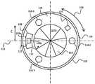
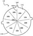
도 4a는 도 2의 화살표 A로 나타낸 방향에 있어서의 예시적인 출구 구조체(100)의 평면도를 나타내는 개략도이다. 구체적으로, 도 4는 설명의 편의상 마개(106)를 제거한 출구 구조체(100)의 제2 커넥터부(110)의 평면도를 도시한다. 이 예시에 있어서, 제2 커넥터부(110)는 실질적으로 원통형이고, 노즐 구조체(202)를 수용 및/또는 결합하기 위한 하나 이상의 구조적 특징부를 포함하는 어댑터 구조체를 포함한다. 예를 들어, 어댑터 구조체는 도 3에 나타낸 흡인 방향(282)에 대하여 수직하게 연장되는 실질적으로 평면인 인터페이스면(116), 및 인터페이스면(116)의 외부 에지로부터 수직하게 직립되는 원주방향 벽(114)을 포함할 수 있다. 인터페이스면(116)은 노즐 구조체(202)의 튜브(204)를 수용하기 위한 출구 개구(112)를 규정할 수 있다. 원주방향 벽(114)의 내부면은 노즐 구조체(202)의 외주부와 상보적일 수 있으며, 이로써 제2 커넥터부(110)의 인터페이스면(116)과 결합하도록 노즐 구조체(202)를 가이드하는 가이드면으로서 기능하게 된다.4A is a schematic view showing a plan view of an
제2 커넥터부(110)의 어댑터 구조체는 또한, 노즐 구조체(202)를 제2 커넥터부(110)의 인터페이스면(116)에 대하여 결합 위치에서 해제 가능하게 유지하기 위한 유지 구조체(118)를 포함할 수 있다. 예를 들어, 유지 구조체(118)는 하나 이상의 유지 요소(118-1 내지 118-3)를 포함할 수 있다. 본 예시에 있어서, 유지 요소(118-1 내지 118-3)는 노즐 구조체에 대하여 견인 평향력을 가해서, 노즐 구조체(202)를 제2 커넥터부(110)에 대하여 결합 위치에 해제 가능하게 유지한다.The adapter structure of the
제1 예시에 있어서, 하나 이상의 유지 요소(118-1 내지 118-3) 중 적어도 하나는, 노즐 구조체(202)에 배치되는 상보적인 자기 유지 요소(예컨대, 영구 자석)에 의해 생성되는 자기장에 응하여 해당 상보적인 자기 유지 요소에 대하여 자기 편향력을 가하는 자화 가능한 유지 요소(예컨대, 강자성 재료)를 포함할 수 있다. 제2 예시에 있어서, 하나 이상의 유지 요소(118-1 내지 118-3) 중 적어도 하나는, 노즐 구조체(202)에 배치되는 상보적인 자화 가능한 유지 요소(예컨대, 강자성 재료)의 근처에 위치될 경우에 해당 상보적인 자화 가능한 요소에 대하여 자기 편향력을 가하는 자기장을 생성하는 자기 유지 요소(예컨대, 영구 자석)를 포함할 수 있다. 제3 예시에 있어서, 하나 이상의 유지 요소(118-1 내지 118-3) 중 적어도 하나는, 노즐 구조체(202)에 배치되는 반대 극성의 상보적인 자기 유지 요소의 근처에 위치될 경우에 해당 상보적인 자기 요소에 대하여 자기 편향력을 가하는 자기장을 생성하는 자기 유지 요소(예컨대, 영구 자석)를 포함할 수 있다. 3가지 경우 모두에 있어서, 자기 유지 요소와 자화 가능한 유지 요소 또는 자기 유지 요소와 자기 유지 요소로 이루어지는 상보적인 쌍은, 서로에 대하여 상대적으로 매우 근접하여 위치될 경우, 노즐 구조체(202)를 제2 커넥터부(110)에 대하여 결합 위치에서 해제 가능하게 유지하도록 작용하는 견인 편향력을 생성하도록 협동한다. 이들 예시에 따르면, 노즐 구조체(202) 및 제2 커넥터부(110)는 유지 요소(118-1 내지 118-3)에 의해 생성되는 편향력을 극복하기에 충분한 크기의 분리력을 수동으로 적용함으로써 결합 위치로부터 해제 또는 분리될 수 있다. 예를 들어, 노즐 구조체(202)에는, 이 분리력의 수동 적용이 가능하도록 핸들(도시되지 않음)이 제공될 수 있다. 이들 예시에 있어서는, 사용자가 임의의 형태의 기계식 체결 수단을 조작할 필요가 없으며, 이로써 노즐 구조체(202) 및 출구 구조체(100)의 편리한 결합 및 분리가 제공된다.In a first example, at least one of the one or more retaining elements 118-1 to 118-3 is in response to a magnetic field generated by a complementary magnetic retaining element (e.g., a permanent magnet) disposed in the
작동시에, 흡인 시스템에 의해 생성되는 흡입 압력은, 노즐 구조체(202)를 결합 위치에 유지하기 위해, 복수의 유지 요소(118-1 내지 118-3)에 의해 제공되는 자기력에 의해 제공되는 힘을 초과하는 편향력을 생성하도록 작용할 수 있다는 점을 이해할 것이다. 이와 관련하여, 복수의 유지 요소(118-1 내지 118-3)에 의해 제공되는 자기력은 용기(300)의 흡인에 앞서 출구 구조체(100)에 대하여 노즐 구조체(202)를 결합 위치로 안내하는 힘으로서 간주될 수 있고, 흡인이 시작되면 지배적인 유지력은 흡입 시스템에 의해 생성되는 흡입 압력에 의해 제공된다.In operation, the suction pressure generated by the suction system is the force provided by the magnetic force provided by the plurality of holding elements 118-1 to 118-3 to hold the
상보적인 자기 유지 요소와 자화 가능한 유지 요소, 또는 상보적인 자기 유지 요소와 자기 유지 요소를 사용하면, 분말계 축조 재료 환경에서의 작동시에, 유지 구조체(118)가 유효해지는 것이 보장된다. 즉, 유지 구조체(118)에 의해 제공되는 견인 편향력은 커넥터(107) 및/또는 노즐 구조체(202) 표면상에서의 가능한 분말 축적에 의한 영향을 받지 않는다. 대조적으로, 노즐 구조체(202)와 출구 구조체(100)를 결합 위치에 유지하기 위한 기계식 수단은 분말계 축조 재료의 축적과 연관되는 막힘 또는 들러붙음(sticking)으로 인해 제대로 기능하지 못하거나 덜 유효해질 수 있다.Using a complementary magnetic holding element and a magnetizable holding element, or a complementary magnetic holding element and magnetic holding element, ensures that the holding structure 118 becomes effective when operating in a powder-based building material environment. In other words, the traction deflection force provided by the holding structure 118 is not affected by possible powder accumulation on the
일부 예시에 있어서, 제2 커넥터부(110) 및 노즐 구조체(202)는 플라스틱 재료와 같은 자화 불가능 재료로 형성 또는 부분적으로 형성될 수 있다. 이러한 실시형태에 있어서, 복수의 유지 요소(118-1 내지 118-3)는 노즐 구조체(202)를 제2 커넥터부(110)에 대하여 특정 방위로 강제함으로써 부가적인 정렬 기능을 제공한다. 추가의 예시에 있어서, 복수의 유지 요소(118-1 내지 118-3)는, 제2 커넥터부(110)에 대한 노즐 구조체(202)의 초기 정렬에 따라, 유지 요소(118-1 내지 118-3)의 특정 배열 및/또는 개수에 의해 규정되는 복수의 가능한 방위 중 특정 방위로 노즐 구조체(202)를 강제할 수 있다.In some examples, the
일부 예시에 있어서, 커넥터(107)에 배치되는 유지 요소(118-1 내지 118-3)의 개수는 노즐 구조체(202)에 배치되는 유지 요소(210-1 내지 210-3)의 개수보다 많거나 또는 적을 수 있다. 예를 들어, 커넥터(107)는 노즐 구조체(202)에 배치되는 복수의 유지 요소(210-1 내지 210-3)에 상보적인 단일의 유지 요소를 포함할 수 있다. 따라서, 본 문맥에 있어서, "상보적인(complementary)"이라는 용어는 제각기 커넥터(107) 및 노즐 구조체(202)에 있는 유지 요소들 사이에 반드시 일대일 관계를 의미하는 것은 아니라는 점을 이해할 것이다.In some examples, the number of retaining elements 118-1 to 118-3 disposed in the
"자화 가능한 재료(magnetisable material)"라는 용어는 외부 자기장을 받거나 또는 외부 자기장 내에 놓일 때 자기 특성을 나타내는 임의의 재료를 포함한다는 점을 이해할 것이다. 따라서, 이 용어는 철(예컨대, 스틸), 니켈 및/또는 코발트의 합금과 같은 강자성 재료를 포함한다. 따라서, 본 개시의 문맥에 있어서, "자화 가능한 유지 요소(magnetisable retaining element)"는, 상보적인 "자기 유지 요소(magnetic retaining element)"의 자기장 내에 놓일 때 자성을 띠는 유지 요소를 의미하고, 이로써 위에서 논의한 균등하고 반대인 자기 견인 편향력이 생성된다.It will be understood that the term "magnetisable material" includes any material that exhibits magnetic properties when subjected to or placed in an external magnetic field. Thus, the term includes ferromagnetic materials such as alloys of iron (eg, steel), nickel and/or cobalt. Thus, in the context of the present disclosure, "magnetisable retaining element" means a retaining element that becomes magnetic when placed in the magnetic field of a complementary "magnetic retaining element", whereby The equal and opposite magnetic traction deflection forces discussed above are created.
일부 예시에 있어서, 하나 이상의 유지 요소(118-1 내지 118-3)는 출구 개구(112)와 동축인 제2 커넥터부(110)의 환형 구역에 배치된다. 환형 구역은 출구 개구(112)에 근접할 수 있다. 하나 이상의 유지 요소(118-1 내지 118-3)는 커넥터(107)와 노즐 구조체(202) 사이에 상대적으로 균일한 견인 편향력 분포를 제공하기 위해 환형 구역에 원주방향으로 분포될 수 있다. 하나 이상의 유지 요소(118-1 내지 118-3)는 제2 커넥터부(110)의 인터페이스면(116)으로부터 오목하게 형성된 각각의 포켓 내에 유지될 수 있다. 도 4a에 도시된 예시에 있어서, 유지 요소(118-1 내지 118-3)는 제2 커넥터부(110)의 인터페이스면(116)과 동일 평면인 선단면을 포함한다. 대안으로서, 하나 이상의 유지 요소(118-1 내지 118-3)는, 출구 구조체(100)의 외부에서 보이지 않도록, 제2 커넥터부(110)에서 인터페이스면(116) 아래에 배치될 수 있다.In some examples, one or more retaining elements 118-1 to 118-3 are disposed in an annular region of the
제2 커넥터부(110)는, 도 4a의 화살표(126)로 도시된 방향으로 제1 커넥터부(108)에 대한 제2 커넥터부(110)의 상대적인 회전이 가능하도록, 제1 커넥터부(108)에 회전 가능하게 연결될 수 있다. 일부 예시에 있어서, 이 상대적인 회전은 화살표(282)로 도시된 흡인 채널에 대하여 수직하고 인터페이스면(116)과 실질적으로 동일 평면인 평면에서 제공될 수 있다. 이 상대적인 회전은 사용자가 제2 커넥터부(110)를 소정의 또는 편리한 방위로 회전시킬 수 있게 한다. 예를 들어, 제2 커넥터부(110)는 어댑터 구조체를 노즐 구조체(202)의 방위에 맞게 정렬하도록 회전될 수 있고, 이로써 용기(300) 및/또는 노즐 구조체(202)를 재배향할 필요 없이 노즐 구조체(202)가 어댑터 구조체와 결합할 수 있게 된다. 유사하게, 제2 커넥터부(110)는 마개(106)를 용기(300)의 특정한 구조적 특징부에 대하여 특정 방위로 위치시키도록 회전될 수 있다. 예를 들어, 제2 커넥터부(110)는, 마개(106)가 통기 구조 또는 다른 개구(도시되지 않음)와 같은 용기(300)의 구조적 특징부에 의한 간섭 없이 개방 구성으로 개방될 수 있으며 또한 닫힐 수 있게 하는 방위로 회전될 수 있다. 이 제2 커넥터부(110)의 제1 커넥터부(108)에 대한 회전은 출구 구조체(100)에 "일차적인(primary)" 또는 "거친(coarse)" 정렬 메커니즘을 제공하는 것으로 간주될 수 있다. 이 일차적인 정렬 메커니즘은, 예를 들어 용기(300)와 출구 구조체(100)의 조립 도중에 도입되는, 예를 들어 제1 커넥터부(108)와 용기(300) 사이의 정렬에 있어서의 임의의 편차를 해결할 수 있다.The
일부 예시에 있어서, 출구 구조체(100)에는, 용기(300)의 사용과 관련된 데이터의 저장을 위해, 매립형 스마트 칩과 같은 비일시적인 컴퓨터 판독 가능한 저장 매체(도시되지 않음)가 제공될 수 있다. 예를 들어, 비일시적인 컴퓨터 판독 가능한 저장 매체는 용기(300) 및 그 안에 보관된 축조 재료의 안전한 작동 및 사용을 보장하기 위해 3D 프린터(402)에 의해 사용 가능한 데이터를 저장할 수 있다. 3D 프린터(402)와 비일시적인 컴퓨터 판독 가능한 저장 매체 사이의 데이터 통신이 가능하도록, 제2 커넥터부(110)는 노즐 구조체(202)의 선단면으로부터 돌출 또는 연장되는 데이터 상호접속 구조체(212)를 수용하기 위해, 인터페이스면(116)으로부터 제2 커넥터부(110) 내로 오목하게 형성된 소켓(120)을 포함할 수 있다. 소켓(120)에는, 데이터 상호접속부(212)의 데이터 인터페이스(213)와 결합해서 출구 구조체(100)와 노즐 구조체(202) 사이의 데이터 접속을 제공하기 위해 소켓(120)의 바닥부에 배치되는 하나 이상의 데이터 접점(122)이 제공될 수 있다. 이 데이터 접속은, 예를 들어 전술한 바와 같이 비일시적인 컴퓨터 판독 가능한 저장 매체 및 3D 프린터(402)에 대한 데이터의 전송에 사용될 수 있다.In some examples, the
일부 예시에 있어서, 소켓(120)은 복수의 유지 요소(118-1 내지 118-3)를 포함하는 인터페이스면의 환형 구역에 배치될 수 있다. 또한, 소켓(120)은 복수의 유지 요소(118-1 내지 118-3) 중 특정 유지 요소에 실질적으로 대향해 있는 환형 구역의 영역에 놓일 수 있다. 일부 예시에 있어서, 소켓(120) 및 특정 유지 요소는 용기(300)의 하나 이상의 특정한 특징부와 정렬되는 축선(111) 상에 놓일 수 있다. 예를 들어, 해당 축선은 용기(300)의 측벽과 실질적으로 평행할 수 있다.In some examples, the
일부 예시에 있어서, 소켓(120)은 또한, 제2 커넥터부(110)에 대하여 노즐 구조체(202)의 정렬을 제공하는 정렬 소켓으로서 기능할 수도 있다. 이와 관련하여, 소켓(120)은 데이터 상호접속 구조체(212)를 소켓(120) 내부의 정확한 위치로 가이드하도록 구성되는 하나 이상의 정렬면을 포함할 수 있다. 예를 들어, 하나 이상의 정렬면은 데이터 인터페이스(213)를 하나 이상의 데이터 접점(122)과 정확히 결합하도록 가이드 또는 강제하기 위해 소켓(120)의 바닥을 향해 수렴하도록 구성되는 내부 정렬면일 수 있다. 제1 커넥터부(108)와 제2 커넥터부(110) 사이의 상대적인 회전이 전술한 방식으로 제공되는 예시에 있어서, 소켓(120)에 의해 제공되는 정렬은, 데이터 인터페이스(213)와 하나 이상의 데이터 접점(122) 사이의 정밀한 결합을 보장해서 비일시적인 컴퓨터 판독 가능한 저장 매체에 대한 신뢰도 있는 데이터 전송을 가능하게 하는, "이차적인(secondary)" 또는 "미세한(fine)" 정렬 메커니즘을 제공하는 것으로 간주될 수 있다.In some examples, the
소켓(120)은, 도 4a에 도시된 바와 같이, 실질적으로 만곡된 외벽(120a) 및 실질적으로 만곡된 내벽(120b)을 포함할 수 있다. 일부 예시에 있어서, 외벽(120a) 및 내벽(120b) 중 하나 또는 둘 모두는 어댑터의 원주방향 벽(114)과 실질적으로 동심으로 될 수 있어서, 어댑터의 원주방향 벽(114) 내부에서의 노즐 구조체(202)의 회전에 의해 데이터 상호접속 구조체(212)를 소켓(120) 내로 삽입하는 것을 도울 수 있다. 일부 예시에 있어서, 외벽(120a) 및/또는 내벽(120b)의 접선은 용기(300)의 측벽에 대하여 실질적으로 평행할 수 있다.The
일부 예시에 있어서, 노즐 구조체(202)에는, 노즐 구조체(202)가 출구 구조체(100)에 대하여 정확한 결합 위치에 있을 때 작동되는 마이크로 스위치와 같은 작동 스위치(214)가 제공된다. 3D 프린터(402)는 작동 스위치(214)의 상태를 모니터링해서, 용기(300)의 흡인을 조절할 수 있으며 출구 구조체(100)에 매립된 비일시적인 컴퓨터 판독 가능한 매체에 대한 그 사이에서의 데이터 전송을 제어할 수 있다. 예를 들어, 3D 프린터(402)는 작동 스위치의 상태를 모니터링해서, 노즐 구조체(202)와 출구 구조체(100) 사이의 정확한 결합이 작동 스위치(214)의 작동에 의해 확인되었을 때에만 용기의 흡인이 수행되게 할 수 있다. 이러한 방식으로, 노즐 구조체(202)와 출구 구조체(100) 사이의 미비한 또는 불완전한 결합에 기인하는 용기(300)로부터 주위 환경으로의 축조 재료의 바람직하지 않은 방출이 회피 또는 감소될 수 있다. 유사하게, 3D 프린터(402)는, 노즐 구조체(202)와 출구 구조체(100) 사이의 정확한 결합, 및 그에 따른 데이터 인터페이스(213)와 하나 이상의 데이터 접점(122) 사이의 정확한 결합이 확인되었을 때에만 데이터 인터페이스(213)를 통한 비일시적인 컴퓨터 판독 가능한 매체에 대한 데이터 전송이 수행되게 할 수 있다. 이러한 방식으로, 데이터 인터페이스(213)와 하나 이상의 데이터 접점(122) 사이의 부정확한 결합에 기인하는 데이터 손실이 회피될 수 있다.In some examples, the
작동 스위치(214)의 기계식 작동은 제2 커넥터부(110)의 인터페이스면(116)으로부터 연장 또는 돌출되는 돌출부와 같은 작동 구조체(124)에 의해 제공될 수 있다. 작동 구조체(124)는 노즐 구조체(202)에 배치되는 작동 스위치(214)의 위치와 상보적인 인터페이스면(116) 상의 위치에 놓인다. 따라서, 노즐 구조체(202)가 출구 구조체(100)와 정확히 결합하게 될 때, 작동 구조체(124)가 작동 스위치(214)와 결합해서 기계식으로 작동시킨다.Mechanical actuation of the
일부 예시에 있어서, 소켓(120)은 환형 구역에서 복수의 유지 요소(118-1 내지 118-3) 중 제1 유지 요소와 복수의 유지 요소(118-1 내지 118-3) 중 제2 유지 요소 사이에 배치되고, 작동 구조체(124)는 환형 구역에서 복수의 유지 요소(118-1 내지 118-3) 중 제2 유지 요소와 복수의 유지 요소(118-1 내지 118-3) 중 제3 유지 요소 사이에 배치된다.In some examples, the
일부 예시에 있어서, 작동 구조체(124)의 높이는, 데이터 인터페이스(213)가 소켓(120) 내에 배치된 데이터 접점(122)으로부터 분리되기 전에 작동 스위치(214)가 해제 또는 분리되는 것을 보장하도록 선택된다. 이는, 3D 프린터(402)가 노즐 구조체(202)와 출구 구조체(100) 사이에서의 데이터 전송을 중단할 수 있게 해서, 데이터 인터페이스(213)와 데이터 접점(122) 사이의 예상치 못한 분리에 기인하는 잠재적인 데이터 손실을 겪는 것을 회피할 수 있게 한다. 예를 들어, 작동 구조체(124)는 결합 위치로부터의 노즐 구조체(202)의 소정의 제1 변위 범위에 대하여 노즐 구조체(202)에서 작동 스위치(214)와 결합하도록 구성될 수 있으며, 하나 이상의 데이터 접점(122)은 결합 위치로부터의 노즐 구조체(202)의 소정의 제2 변위 범위에 대하여 데이터 인터페이스(213)와 결합하도록 구성될 수 있고, 이때 소정의 제2 변위 범위는 소정의 제1 변위 범위보다 크다. 이는, 데이터 인터페이스(213)가 소켓(120) 내에 배치된 데이터 접점(122)에서 분리되기 전에 작동 스위치(214)가 비활성화 또는 분리되는 것을 보장한다.In some examples, the height of the
유지 수단(118)은 작동 스위치(214)를 기계식으로 작동시키기에 충분한 견인 편향력을 제공하도록 구성될 수 있다. 예를 들어, 커넥터(107) 및 노즐 구조체(202)의 상보적인 유지 요소들은, 노즐 구조체(202)가 제2 커넥터부(110)의 인터페이스면(116)으로부터 소정의 분리 거리 내에 있을 경우에는, 자기력이 노즐 구조체(202)를 결합 위치 내로 견인 또는 강제해서 작동 스위치(214)를 기계식으로 작동시키기에 충분하도록 구성될 수 있다. 일부 예시에 있어서, 소정의 분리 거리는 작동 구조체(124)의 높이 이상일 수 있다.The retaining means 118 may be configured to provide sufficient traction biasing force to mechanically actuate the
일부 예시에 따르면, 출구 구조체(100)는 결합 및 분리 프로세스 도중에 축조 재료의 손실을 줄이기 위해 각각의 밸브 구조체(113)를 추가로 포함할 수 있다. 밸브 구조체(113)의 상세는 아래에서 도 7 및 도 8을 참조하여 개시된다.According to some examples, the
도 4b는 도 2의 화살표 B로 나타낸 방향에 있어서의 노즐 구조체(202)의 저면도를 나타내는 개략도이다. 노즐 구조체(202)는 노즐 구조체(202)의 인터페이스면(208)으로부터 수직하게 연장되는 원주형 튜브(204)를 포함한다. 노즐 구조체(202)는, 노즐 구조체(202)를 제2 커넥터부(110)의 인터페이스면(116)에 대하여 결합 위치에 해제 가능하게 유지하기 위한 유지 구조체(210)를 추가로 포함한다. 예를 들어, 유지 구조체(210)는 제2 커넥터부(110)에 배치되는 대응하는 유지 요소(118-1 내지 118-3)에 상보적인 위치에서 노즐 구조체(202)에 배치되는 하나 이상의 유지 요소(210-1 내지 210-3)를 포함할 수 있다.4B is a schematic diagram showing a bottom view of the
도 4a를 참조하여 위에서 논의된 바와 같이, 노즐 구조체(202)의 하나 이상의 유지 요소(210-1 내지 210-3) 중 적어도 하나는, 제2 커넥터부(110)에 배치되는 상보적인 자기 유지 요소(예컨대, 영구 자석)에 의해 생성되는 자기장에 응하여 해당 상보적인 자기 유지 요소에 대하여 자기 편향력을 가하는 자화 가능한 유지 요소(예컨대, 강자성 재료)를 포함할 수 있다. 제2 예시에 있어서, 하나 이상의 유지 요소(210-1 내지 210-3) 중 적어도 하나는, 제2 커넥터부(110)에 배치되는 상보적인 자화 가능한 유지 요소(예컨대, 강자성 재료)의 근처에 위치될 경우에 해당 상보적인 자화 가능한 요소에 대하여 자기 편향력을 가하는 자기장을 생성하는 자기 유지 요소(예컨대, 영구 자석)를 포함할 수 있다. 제3 예시에 있어서, 하나 이상의 유지 요소(210-1 내지 210-3) 중 적어도 하나는, 제2 커넥터부(110)에 배치되는 반대 극성의 상보적인 자기 유지 요소의 근처에 위치될 경우에 해당 상보적인 자기 요소에 대하여 자기 편향력을 가하는 자기장을 생성하는 자기 유지 요소(예컨대, 영구 자석)를 포함할 수 있다. 3가지 경우 모두에 있어서, 자기 유지 요소와 자화 가능한 유지 요소, 또는 자기 유지 요소와 자기 유지 요소로 이루어지는 상보적인 쌍은, 서로에 대하여 상대적으로 매우 근접하여 위치될 경우, 노즐 구조체(202)를 제2 커넥터부(110)에 대하여 결합 위치에서 해제 가능하게 유지하도록 작용하는 견인 편향력을 생성하도록 협동한다. 이들 예시에 따르면, 노즐 구조체(202) 및 제2 커넥터부(110)는 유지 요소에 의해 생성되는 편향력을 극복하기에 충분한 크기의 분리력을 수동으로 적용함으로써 결합 위치로부터 해제 또는 분리될 수 있다. 예를 들어, 노즐 구조체(202)에는, 이 분리력의 수동 적용이 가능하도록 핸들이 제공될 수 있다. 이들 예시에 있어서는, 사용자가 임의의 형태의 기계식 체결 수단을 조작할 필요가 없으며, 이로써 노즐 구조체(202) 및 출구 구조체(100)의 편리한 결합 및 분리가 제공된다.As discussed above with reference to FIG. 4A, at least one of the one or more holding elements 210-1 to 210-3 of the
일부 예시에 있어서, 하나 이상의 유지 요소(210-1 내지 210-3)는 튜브(204)와 동축인 노즐 구조체(202)의 환형 구역에 배치된다. 환형 구역은 튜브(204)에 근접할 수 있다. 하나 이상의 유지 요소(210-1 내지 210-3)는 커넥터(107)와 노즐 구조체(202) 사이에 상대적으로 균일한 견인 편향력 분포를 제공하기 위해 환형 구역에 원주방향으로 분포될 수 있다. 하나 이상의 유지 요소(210-1 내지 210-3)는 노즐 구조체(202)의 인터페이스면(208)으로부터 오목하게 형성된 각각의 포켓 내에 유지될 수 있다. 도 4b에 도시된 예시에 있어서, 유지 요소(210-1 내지 210-3)는 노즐 구조체(202)의 인터페이스면(208)과 동일 평면인 선단면을 포함한다. 대안으로서, 하나 이상의 유지 요소(210-1 내지 210-3)는, 노즐 구조체(202)의 외부에서 보이지 않도록, 노즐 구조체(202)에서 인터페이스면(208) 아래에 배치될 수 있다.In some examples, one or more retaining elements 210-1-210-3 are disposed in an annular region of the
일부 예시에 따르면, 노즐 구조체(202)는 결합 및 분리 프로세스 도중에 축조 재료의 손실을 줄이기 위해 밸브 구조체(230)를 추가로 포함할 수 있다. 밸브 구조체(230)의 상세는 아래에서 도 7 및 도 8을 참조하여 개시된다.According to some examples, the
도 5는, 도 4a의 화살표 C의 방향에서 본, 도 4a의 출구 구조체(100)의 부분 단면도를 도시하는 개략도이다. 도 4a 및 도 4b를 참조하여 위에서 논의된 특징부에 더하여, 도 5는 출구 구조체(100)와 용기(300) 사이의 인터페이스의 예시를 도시한다. 이 예시에 있어서, 출구 구조체(100)는 용기(300)의 상부벽(306)을 통해 삽입되어서 그 안에 수용된 저장소(302)에 연결된다. 특히, 출구 구조체의 제1 커넥터부(108)는 저장소(302)의 목부(304)와 결합해서 출구 구조체(100)와 저장소(302) 사이에 실질적으로 기밀 밀봉을 제공한다. 예를 들어, 제1 커넥터부(108)는, 저장소(302)의 목부(304)와 억지 끼워맞춤으로 결합해서 실질적으로 기밀 밀봉을 제공하는 원통형 벽(109)을 포함할 수 있다. 대안으로서, 제1 커넥터부(108)의 원통형 벽(109)에는 원통형 부분의 내벽 상에 암나사산(도시되지 않음)이 제공될 수 있고, 이는 목부(304)의 외벽 상의 수나사산(도시되지 않음)과 상보적으로 결합한다. 대안적인 예시에 있어서, 제1 커넥터부(108)의 원통형 벽(109)에는 원통형 부분의 외벽 상에 수나사산(도시되지 않음)이 제공될 수 있고, 이는 목부(304)의 내벽 상의 암나사산(도시되지 않음)과 상보적으로 결합한다. 각각의 예시에 있어서, 출구 구조체(100)는 제1 커넥터부(108)를 목부(304)에 대하여 체결하거나 또는 체결을 풀어서 편리하게 저장소에 대하여 연결 및 분리될 수 있다.FIG. 5 is a schematic diagram showing a partial cross-sectional view of the
도 5에 나타낸 예시에 따르면, 출구 구조체(100)는 또한, 출구 구조체의 제2 커넥터부(110)의 바닥면으로부터 저장소(302)의 목부(304)를 향해 연장되는 튜브부(130)를 포함할 수 있다. 일부 예시에 있어서, 튜브부(130)는 목부(304)를 통해 저장소(302) 내로 통과할 수 있다. 도 5에 나타낸 예시에 있어서, 튜브부(130)는 도 2 및 도 3에 도시된 수집 구조체(102)에 연결해서 흡인 채널(103)의 상부 구간을 마련하도록 제공된다. 대안으로서, 튜브부(130)는 수집 구조체(102)의 일체형 부분일 수 있고, 위에서 논의된 바와 같이 저장소(302)의 바닥 영역까지 연장된다. 도 5에 나타낸 예시에 있어서, 튜브부(130)는 제2 커넥터부(110)의 바닥면에 연결되는 플랜지부(131)를 포함한다. 플랜지부(131)는 접착제 또는 나사 체결부와 같은 임의의 적절한 고정 수단을 이용해서 제2 커넥터부(110)에 고정될 수 있다. 대안으로서, 튜브부(130)는 제2 커넥터부(110)의 일체형 부분일 수 있고, 그 경우에는 플랜지부(131)가 필요없게 될 수도 있다. 위 두 경우에 있어서, 튜브부(130)는 저장소(302)로부터 축조 재료의 공압 이송을 위해 노즐 구조체(202)의 튜브(204)를 수용하도록 제2 커넥터부(110)의 출구 개구(112)와 실질적으로 동축이 된다.According to the example shown in FIG. 5, the
도 4a 및 도 4b를 참조하여 위에서 논의된 바와 같이, 제2 커넥터부(110)에는, 노즐 구조체(202)로부터 돌출하는 데이터 상호접속 구조체(212)를 수용하기 위해 인터페이스면(116)으로부터 오목하게 형성된 소켓(120)이 제공된다. 이 관계는, 제각기 제2 커넥터부(110)에서의 소켓(120)과 노즐 구조체(202)에서의 데이터 상호접속 구조체(212)의 상보적인 위치들을 도시하는 도 5에 추가로 나타나 있다. 이 예시에 있어서, 소켓(120)은 소켓(120)의 바닥을 향해 수렴하는 측벽들을 포함하고, 이로써 데이터 상호접속 구조체(212)를 소켓(120) 내부의 정확한 위치로 가이드 또는 강제하는 정렬면으로서 작용하게 된다.As discussed above with reference to FIGS. 4A and 4B, the
도 5는 또한, 제각기 노즐 구조체(202)의 작동 스위치(214)와 제2 커넥터부(110)의 작동 구조체(124)의 상보적인 위치들을 도시한다. 유사하게, 도 5는 제2 커넥터부(110)에 배치되는 유지 요소(118-2)와 노즐 구조체(202)에 배치되는 유지 요소(210-2)의 상보적인 위치들을 도시한다. 도 5에 도시된 예시에 있어서, 제2 커넥터부(110)에 배치되는 유지 요소(118-2)는, 아래에서 도 6a 및 도 6b를 참조하여 더 상세하게 설명되는 포켓 내에 놓이거나 또는 안착된다.5 also shows the complementary positions of the
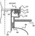
도 6a 및 도 6b는 제1 커넥터부(108) 및 제2 커넥터부(110)에 대한 로킹 메커니즘의 일례를 도시한다. 이 예시에 있어서, 로킹 메커니즘은 제1 커넥터부(108)를 제2 커넥터부(110)에 고정하기 위해 협동하는, 실질적으로 원통부를 포함하는 로킹 부재(128), 래칭 부재(136) 및 래칭면(138)을 포함한다. 이 예시에 따르면, 로킹 부재(128)의 기능은 헤드부(128a) 및 스템부(128b)를 포함하는 나사 또는 볼트의 형태를 취하는 유지 요소(118-2)에 의해 편리하게 제공된다. 로킹 부재(128)의 헤드부(128a)는 인터페이스면(116)으로부터 제2 커넥터부(110) 내로 오목하게 형성된 상보적인 포켓(132)에 수용된다. 로킹 부재(128)의 스템부(128b)는 포켓(132)의 바닥면에 있는 오리피스로부터 하향으로 연장되는 캐비티(134)에 수용된다. 헤드부(128a)의 직경은 상보적인 포켓(132)의 직경에 대응하도록 선택될 수 있다. 예를 들어, 헤드부의 직경은 적절하게 8 mm, 10 mm 또는 12 mm 일 수 있다.6A and 6B show an example of a locking mechanism for the
캐비티(134)는, 로킹 부재(128)의 스템부(128b)가 캐비티(134) 내에 놓일 때 해당 스템부에 인접하여 위치되며 제2 커넥터부(110)와 일체로 되는 하나 이상의 측벽을 포함할 수 있다. 특히, 측벽들 중 적어도 하나는 제1 커넥터부(108)의 래칭면(138)과 결합하도록 구성되는 래칭 부재(136)로서 기능한다. 래칭 부재(136)는 탄성 재료로 형성되고, 래칭 부재(136)의 적어도 일부는 캐비티(134) 내로 연장되므로, 로킹 부재(128)가 캐비티 내에 안착될 때, 래칭 부재(136)가 캐비티(134)로부터 바깥쪽으로 변위되어서 제1 커넥터부의 래칭면(138)에 결합한다.The
제2 커넥터부(110)의 래칭 부재(136)와 제1 커넥터부(108)의 래칭면(138) 사이의 결합은 제1 커넥터부(108)와 제2 커넥터부(110)의 분리를 방지 또는 막도록 구성된다. 예를 들어, 래칭면(138)은 도 6a 및 도 6b에 도시된 바와 같이, 제1 커넥터부(108)의 내부벽에 원주방향 홈으로 마련될 수 있다. 원주방향 홈은 내부벽의 원주부 전체에 걸쳐 이어지거나 또는 내부벽의 원주부의 일부분(즉, 내부벽의 원호)에 걸쳐 이어질 수 있다. 이 예시에 있어서, 래칭 부재(136)는 원주방향 홈 내부에서 원주방향으로 자유롭게 움직일 수 있고, 이로써 제1 커넥터부(108)와 제2 커넥터부(110) 사이의 상대적인 회전을 허용하면서 분리를 방지한다. 대안으로서, 래칭 부재(136)와 래칭면(138) 사이의 마찰이 제1 커넥터부와 제2 커넥터부 사이의 상대적인 회전을 방지하기에 충분할 수 있다. 추가적인 예시에 있어서, 래칭면(138)은 제1 커넥터부(108)의 내부벽에 노치 또는 함몰부로 마련될 수 있으며, 이로써 제1 커넥터부(108)와 제2 커넥터부(110)의 상대적인 회전 및 분리가 방지된다. 일부 예시에 있어서, 제1 커넥터부(108)의 내부벽에는 복수의 노치가 마련될 수 있으며, 이로써 제2 커넥터부(110)가 제1 커넥터부(108)에 대하여 복수의 방위로 각각 로킹될 수 있게 된다.The coupling between the latching
도 6a는 래칭 부재(136)를 변위시키기 위해 로킹 부재(128)를 캐비티(134) 내로 삽입하기 전의 로킹 메커니즘의 일례를 도시한다. 특히, 도 6a는 래칭 부재(136)가 제1 커넥터부(108)의 래칭면(138)으로부터 분리되도록 부분적으로 캐비티(134) 내로 연장되어 있는 것을 도시한다. 로킹 부재(128)가 캐비티 내로 삽입되면, 도 6b에 도시된 바와 같이, 로킹 부재(128)의 스템(128b)은 래칭 부재(136)를 캐비티로부터 변위시켜서 제1 커넥터부(108)의 래칭면(138)과 결합하도록 래칭 부재(136)를 밀어붙이거나 또는 밀어낸다.6A shows an example of a locking mechanism prior to inserting the locking
로킹 부재(128)는 수나사산을 포함하는 나사 또는 볼트의 형태를 취할 수 있다. 이러한 예시에 있어서, 캐비티의 측벽들은, 로킹 부재(128)가 캐비티 내에 유지되는 것을 보장하기 위해 로킹 부재(128)의 수나사산이 측벽들을 꿰뚫어서 파지할 수 있도록, 로킹 부재(128)에 대한 억지 끼워맞춤을 제공할 수 있다. 대안적으로, 로킹 부재(128)는 억지 끼워맞춤만으로, 또는 접착제와 같은 임의의 다른 적절한 유지 수단을 이용해서 캐비티 내에 유지될 수 있다.The locking
위에서 논의된 바와 같이, 유지 요소(118-1 내지 118-3)는 도 6a 및 도 6b에 나타낸 바와 같이 로킹 부재로서 기능할 수도 있다. 이러한 예시에 있어서, 적어도 로킹 부재(128)의 헤드부(128a)는 도 4a 및 도 4b를 참조하여 위에서 논의된 해제 가능한 결합을 제공하기 위해 자기 재료 또는 자화 가능한 재료로 형성된다. 이러한 방식으로, 커넥터 출구 구조체(100)의 부품의 총 개수 및 조립에 필요한 시간이 줄어든다.As discussed above, retaining elements 118-1 through 118-3 may function as locking members as shown in FIGS. 6A and 6B. In this example, at least the
도 6a 및 도 6b가 단 하나의 로킹 부재(128) 및 대응하는 캐비티(134)를 나타내고 있지만, 복수의 로킹 부재(128) 및 각각의 캐비티(134)가 제공될 수 있음을 이해할 것이다. 예를 들어, 도 4a에 나타낸 복수의 유지 요소(118-1 내지 118-3) 각각은 또한, 도 6a 및 도 6b를 참조하여 전술한 방식으로 로킹 부재(128)로서 기능할 수도 있다.Although FIGS. 6A and 6B show only one locking
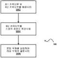
도 9는 도 6a 및 도 6b를 참조하여 위에서 논의된 커넥터(107)를 조립하는 방법(900)을 도시하는 흐름도이다. 제1 스텝에 있어서, 사용자는 제1 커넥터부(108) 및 제2 커넥터부(110)를 도 6a에 도시된 배열로 배향시킨다(스텝 S902). 다음으로, 사용자는 제1 커넥터부(108)에 대하여 바람직한 또는 원하는 정렬로 제2 커넥터부(110)를 회전시킨다(스텝 S904). 마지막으로, 사용자는 로킹 부재(128)를 각각의 캐비티(134) 내로 삽입하여 래칭 부재(136)를 캐비티로부터 변위시켜서 래칭면(138)과 결합시킨다(스텝 S906). 일부 예시에 따르면, 제2 커넥터의 별도의 정렬이 불필요해지도록, 스텝 S902 및 S904는 방위 및 회전을 단일 스텝으로(예컨대, 일괄 작업으로) 제공하도록 결합될 수 있다.9 is a flow chart illustrating a
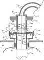
도 7 및 도 8은 축조 재료 출구 구조체(100) 및 축조 재료 노즐 구조체(202)의 밀봉 배열의 일례의 부분 단면도를 도시한다. 도 7 및 도 8은, 노즐 구조체(202)의 예시적인 밸브 요소(230), 및 출구 구조체(100)의 예시적인 밸브 요소(113) 및 돌출부(232)가 또한 도시된다는 점을 제외하고는, 도 5와 유사하다. 도 8은, 도 7과 비교하여 90도 회전된 도면으로서, 명확하게 도시되지 않은 몇몇 특징부를 도시한다.7 and 8 show partial cross-sectional views of an example of the sealing arrangement of the building
도 7 및 도 8을 참조하면, 일부 예시에 있어서, 노즐 구조체(202)는 튜브(204)의 단부 부분(205)에 또는 그 근처에 밸브 요소(230)를 포함한다. 밸브 요소(230)는, 튜브(204)의 단부 부분(205)을 3D 축조 재료 용기(300)의 출구 구조체(100) 내로 삽입시에, 튜브(204)의 단부 부분(205)을 폐쇄하는 제1 구성(도 7 및 도 8에서 실선으로 도시됨)으로부터 튜브(204)의 단부 부분(205)을 개방하는 제2 구성(도 7 및 도 8에서 파선으로 도시됨)으로 변경되도록 배치된다. 명료성을 위해, 도 7 및 도 8은 출구 구조체(100) 내로 삽입된 튜브(204)의 단부 부분(205)을 도시하고 있지 않지만, 도 7 및 도 8에서 파선으로 도시된 노즐 구조체(202)의 밸브 요소(230)의 구성 및 출구 구조체(100)의 밸브 요소(113)의 구성은 튜브(204)의 단부 부분(205)이 마치 출구 구조체(100) 내로 삽입된 것처럼 도시된다는 점을 이해할 것이다. 제2 (개방) 구성은 튜브(204)를 통한 축조 재료의 공압 이송을 위해 기류 및/또는 축조 재료가 튜브(204)를 통과하게 할 수 있다. 제1 (폐쇄) 구성은 기류 및/또는 축조 재료가 튜브(204)를 통과하는 것을 제한 및/또는 방지할 수 있으며, 따라서 축조 재료가 튜브(204)로부터 유출하는 것을 방지할 수 있다.7 and 8, in some examples, the
일부 예시에 있어서, 밸브 요소(230)는 출구 구조체(100)로부터 튜브(204)의 단부 부분(205)의 제거시에 제2 (개방) 구성으로부터 제1 (폐쇄) 구성으로 변경되도록 배치된다. 이는, 노즐 구조체(202)가 축조 재료 용기(300)의 출구 구조체(100)로부터 제거될 때 축조 재료가 유출되는 것을 방지할 수 있다.In some examples,
예를 들어, 밸브 요소(230)는, 아래에서 더 상세하게 설명되는 바와 같이, 출구 구조체(100)의 돌출부(232)에 의해 제1 (폐쇄) 구성으로부터 제2 (개방) 구성으로 변경되도록 배치될 수 있다. 이는, 출구 구조체(100) 내로의 튜브(204)의 삽입시에 구성이 제1 (폐쇄) 구성에서 제2 (개방) 구성으로 자동으로 변경되게 할 수 있다.For example, the
일부 예시에 있어서, 밸브 요소(230)는 제1 (폐쇄) 구성을 향해 편향된다. 이는, 노즐 구조체(202)가 출구 구조체(100)로부터 제거될 때 밸브 요소(230)의 자동(즉, 디폴트) 폐쇄를 허용할 수 있다. 이는, 노즐 구조체(202)가 용기(300)의 출구 구조체(100)에 수용되지 않을 때마다 튜브(204)로부터 축조 재료의 유출의 자동 방지를 허용할 수 있다. 밸브 요소는 임의의 적절한 편향 요소(도시되지 않음), 예컨대 하나 이상의 탄성 부재(예컨대, 스프링), 하나 이상의 편향 중량체, 및/또는 하나 이상의 자기 요소를 이용해서 제1 (폐쇄) 구성을 향해 편향될 수 있다.In some examples, the
일부 예시에 있어서, 밸브 요소(230)는 트뷰(204)의 단부 부분(205)에 또는 그 근처에 피벗 가능하게 장착되고, 도 7의 화살표(238)로 도시된 방향으로 제1 (폐쇄) 구성과 제2 (개방) 구성 사이에서 제1 축선(234)을 중심으로 피벗 가능하다. 제1 축선(234)은 튜브(204)의 길이에 대하여 수직하다. 노즐 구조체(202)는 튜브(204)의 단부에 또는 그 안쪽에 밸브 요소(230)를 피벗 가능하게 장착하기 위한 하나 이상의 장착 요소(도시되지 않음)를 포함할 수 있다. 예를 들어, 밸브 요소(230)는 원형 디스크일 수 있으며 튜브(204)는 중공 실린더일 수 있다. 2개의 액슬(도시되지 않음)이 디스크의 대향하는 에지들 상에서 바깥쪽으로 연장될 수 있고, 해당 액슬들은 제각기 튜브(204) 내부의 대향하는 측면들에 장착되는 2개의 장착 요소(도시되지 않음) 내로 결합하고 그 안에서 자유롭게 회전한다. 따라서, 장착 요소(도시되지 않음)는 액슬을 통해 디스크를 튜브(204) 내부에 유지하고, 2개의 장착 요소(도시되지 않음)에 의해 규정되는 제1 축선(234)을 중심으로 디스크가 피벗할 수 있게 한다. 장착 요소는 튜브(204) 내부에서 밸브 요소(230)의 피벗 동작의 범위를 제한하도록, 예컨대 피벗 동작의 범위를 제1 (폐쇄) 구성과 제2 (개방) 구성 사이로 제한하도록 정지 요소(도시되지 않음)를 포함할 수 있다.In some examples, the
일부 예시에 있어서, 노즐 구조체(202)는 밸브 요소(230)를 제1 (폐쇄) 구성을 향해 편향시키기 위한 편형 요소(도시되지 않음), 예를 들어 탄성 부재(예컨대, 유사(hair spring))를 포함한다. 예를 들어, 유사의 일 단부는 튜브(204)와 기계적으로 접촉할 수 있고, 유사의 타 단부는 밸브 요소(230)와 기계적으로 접촉할 수 있으며, 유사는 밸브 요소(230)를 제1 (폐쇄) 구성으로 편향(강제)시키도록, 즉 디스크의 원주부가 튜브(204)의 내면과 동일 평면 또는 거의 동일 평면으로 되도록 배치될 수 있다.In some examples, the
일부 예시에 있어서, 밸브 요소(230)가 피벗되는 제1 축선(234)은 밸브 요소(230)의 질량 중심으로부터 오프셋될 수 있다. 예를 들어, 제1 축선(234)의 일측에서의 밸브 요소(230)의 질량은 제1 축선(234)의 타측에서의 밸브 요소(230)의 질량보다 클 수 있다. 예를 들어, 제1 축선(234)은 밸브 요소(230)의 기하학적 중심을 통과할 수 있고, 밸브 요소(230)의 일측에서만 여분의 질량체가 추가 또는 결합될 수 있다. 다른 예시로서, 제1 축선(234)은 밸브 요소(230)의 기하학적 중심으로부터 오프셋(도시되지 않음), 예를 들어 밸브 요소(230)의 평면에서 오프셋(도시되지 않음)될 수 있다. 이 경우에는, 균일한 질량 분포의 밸브 요소(230)에 대해서조차, 질량 중심이 제1 축선(234)으로부터 오프셋된다. 제1 축선(234)으로부터 밸브 요소(230)의 질량 중심의 오프셋은 사용시에 밸브 요소(230)가 제1 (폐쇄) 구성으로 편향(강제)되도록 배치될 수 있다. 이 편향 동작은, 예를 들어 스프링에 의해 제공되는 편향 동작을 대신하여, 또는 스프링에 의해 제공되는 편향 동작에 더하여 사용될 수 있다.In some examples, the
일부 예시에 있어서, 노즐 구조체(202)는 튜브(204)의 단부 부분(205)의 측벽에 하나 이상의 작은 구멍(236)을 포함할 수 있다. 구멍(236)은 튜브(204)의 측벽을 통해 연장될 수 있다. 이러한 구멍(236)은 기류가 구멍(236)을 통해 튜브(204) 내로 통과하는 것을 허용할 수 있고, 이로써 용기(300)의 출구 구조체(100)로부터 튜브(204)의 단부 부분(205)의 급속한 및/또는 부적절한 제거의 경우에 축조 재료가 튜브(204)의 단부로부터 유출하는 것이 방지된다.In some examples, the
일부 예시에 있어서, 출구 구조체(100)는 흡인 채널(103) 내로 삽입되는 노즐 구조체(202)의 튜브(204)의 단부 부분(205) 내로 연장되어서 노즐 구조체(202)의 밸브 요소(232)를 제2 (개방) 구성으로 유지하도록 흡인 채널(103)의 내벽으로부터 돌출하는 돌출부(232)를 포함한다. 예를 들어, 돌출부(232)는 흡인 채널(103) 내로의 튜브(204)의 삽입시에 노즐 구조체(202)의 밸브 요소(230)의 구성을 제1 (폐쇄) 구성에서 제2 (개방) 구성으로 변경하도록 배치될 수 있다.In some examples, the
일부 예시에 있어서, 흡인 채널(103)의 내벽은 흡인 채널(103)의 흡인 방향(282)에 평행하고, 돌출부(232)의 제1 구성요소(232a)는 흡인 채널(103)의 내벽을 향한다. 일부 예시에 있어서, 돌출부(232)의 제2 구성요소(232b)는 흡인 채널(103)의 흡인 방향(282)에 평행하게 연장된다. 일부 예시에 있어서, 돌출부(232)는 상향으로, 즉 흡인 채널(103) 내로 삽입되는 노즐 구조체(202)를 향하는 방향으로 흡인 채널(103)의 내벽으로부터 돌출할 수 있다.In some examples, the inner wall of the
일부 예시에 있어서, 돌출부(232)는 실질적으로 L 형상으로 될 수 있다. 예를 들어, 돌출부(232)는 흡인 채널(103)의 길이에 대하여 수직하게 흡인 채널(103) 내로 연장되는 제1 부분(232a), 및 흡인 채널의 길이에 대하여 평행하게 제1 부분(232a)으로부터 연장되는 제2 부분(232b)을 포함해서, 제2 부분(232b)과 흡인 채널(103)의 내벽 사이에 간극, 노치 또는 걸쇠를 규정한다. 튜브(204)의 단부 부분(205)의 측벽이 이 간극에 수용될 수 있다. 돌출부(232)의 다른 형상 및/또는 구성이 튜브(204)의 단부 부분(205) 내로 연장되어서 밸브 요소(230)를 제2 (개방) 구성으로 유지하는 데 사용될 수 있음을 이해할 것이다. 예를 들어, 돌출부(232)는 실질적으로 C 형상(도시되지 않음)일 수 있거나 또는 실질적으로 4분원(도시되지 않음) 또는 다른 곡선(도시되지 않음)으로서 형성될 수 있다. 다른 예시로서, 돌출부(232)는 실질적으로 선형(도시되지 않음)일 수 있으며, 예를 들어 커넥터(107)를 향하도록 흡인 튜브(103)의 내벽에 대하여 정렬될 수 있다.In some examples, the
특정 예시에 있어서, 수집 구조체(102)는 흡인 채널(103)의 적어도 일부분을 규정하는 중공 실린더를 포함할 수 있고 약 45 mm 의 내경을 가질 수 있으며, 돌출부(232)의 제1 부분(232a)은 실린더의 길이에 대하여 수직하게 실린더의 내벽으로부터 약 8 mm 연장될 수 있으며, 돌출부(232)의 제2 부분(232b)은 실린더의 길이에 대하여 평행하게 제1 부분(232a)의 단부로부터 약 10 mm 연장될 수 있다. 실린더의 내벽과 돌출부의 제2 부분(232b) 사이의 결과적인 간극은, 예를 들어 약 5 mm 일 수 있다. 돌출부(232)는, 노즐 구조체가 커넥터(107)에 연결될 때, 노즐 구조체(202)의 튜브(204)의 단부 부분(205) 내로 약 8 mm 만큼 연장될 수 있다.In a specific example, the
일부 예시에 있어서, 돌출부(232)는, 노즐 구조체(202)가 커넥터(107)에 연결될 때, 노즐 구조체(202)의 밸브 요소(230)를 개방(예를 들어, 완전 개방) 구성으로 유지하도록 배치된다. 예를 들어, 돌출부(232)의 제2 부분(232b)은 출구 구조체(100) 내로의 삽입시에 노즐 구조체(202)의 밸브 요소(230)에 대하여 작용할 수 있고, 이로써 밸브 요소(230)의 구성이 제1 (폐쇄) 구성에서 제2 (개방) 구성으로 변경되고, 밸브 요소가 해당 구성으로 유지된다. 돌출부(232)는 출구 구조체(100) 내로의 튜브(204)의 단부 부분(205)의 삽입시에 밸브 요소(230)가 제1 (폐쇄) 구성에서 제2 (개방) 구성으로 자동으로 변경되게 할 수 있다(따라서, 공기 및/또는 축조 재료가 자동으로 튜브(204) 내에서 유동할 수 있게 됨).In some examples, the
일부 예시에 있어서, 돌출부(232)의 원위 단부(232b)는 경사진 부분(232b)을 포함할 수 있다. 예를 들어, 돌출부(232)의 제2 부분(232b)의 원위 단부(232b)는 돌출부(232)의 제2 부분에 대하여 수직이 아닌 각도로 설정될 수 있다. 이는, 튜브(204)의 단부 부분(205)이 출구 구조체(100) 내로 삽입 또는 그로부터 제거될 때, 제1 (폐쇄) 구성과 제2 (개방) 구성 사이에서 밸브 요소(230)의 원활한 변경(즉, 감소된 변화율)을 허용할 수 있다.In some examples, the
일부 예시에 있어서, 돌출부(232)는 커넥터(107)에 대하여 사전 규정된 장소에 위치된다.In some examples, the
위에서 언급된 바와 같이, 일부 예시에 있어서, 출구 구조체(100)에는 노즐 구조체(202)의 데이터 상호접속 구조체(212)를 수용하기 위한 소켓(120)이 제공될 수 있다. 일부 예시에 있어서, 소켓(120)은 또한, 출구 구조체(100)와 노즐 구조체(202)의 정렬을 제공하기 위한 정렬 소켓으로서 기능할 수도 있으며, 돌출부(232)는 소켓(120)에 대하여 사전 규정된 장소에 있을 수 있다. 일부 예시에 있어서, 소켓(120)은 또한, 출구 구조체(100)에 대하여 노즐 구조체(202)의 방위를 소정의 방위로 고정하도록 기능할 수도 있다. 일부 예시에 있어서, 돌출부(232)는 커넥터(107)로부터 사전 규정된 축방향 거리에, 예를 들어 인터페이스면(116)으로부터 사전 규정된 축방향 거리에 위치될 수 있다. 커넥터(107)에 대한 돌출부(232)의 사전 규정된 위치설정은, 노즐 구조체(202)가 커넥터(107)에 연결될 때, 그리고 예를 들어, 노즐 구조체(202)가 커넥터(107)에 완전히 연결되기 전에, 밸브 요소(230)가 돌출부(232)에 의해 완전히 개방되는 것을 허용할 수 있다.As mentioned above, in some examples, the
다른 예시로서, 돌출부(232)는 작동 구조체(124)에 대하여 사전 규정된 장소에 위치될 수 있다. 예를 들어, 돌출부(232)는 작동 구조체(124)로부터 소정의 축방향 거리에 있을 수 있다. 이는, 밸브 요소(230)가 개방 구성에 있을 때, 예를 들어 그 때에만, 노즐 구조체(202)의 작동 스위치(214)가 작동되도록 할 수 있다.As another example, the
일부 예시에 있어서, 노즐 구조체(202)의 튜브(204)의 길이, 튜브(204)의 단부로부터 밸브 요소(230)의 축방향 거리, 및 흡인 채널(103)의 개구로부터 돌출부(232)의 축방향 거리 사이의 관계는, 노즐 구조체(202)가 출구 구조체(100)에 (완전히) 동작 가능하게 연결될 때(예컨대, 작동 스위치(214)가 작동 구조체(124)에 의해 결합되었을 때) 밸브 요소(230)가 돌출부에 의해 (완전히) 개방되도록 배치될 수 있다(즉, 사전 규정됨).In some examples, the length of the
일부 예시에 있어서, 출구 구조체(100)는, 예를 들어 출구 구조체(100)의 내벽의 대향하는 측면들로부터 돌출하는 2개의 돌출부(232)를 포함할 수 있다. 돌출부(232)들은 그들 사이에 흡인 채널(103)의 기하학적 중심으로부터 오프셋되는 축선을 규정할 수 있다. 예를 들어, 오프셋은 흡인 방향(282)에 대하여 수직한 방향으로 존재할 수 있다. 예를 들어, 돌출부(232)들은 그들 사이에 흡인 채널(103)의 기하학적 중심으로부터 흡인 방향(282)에 대하여 수직한 방향으로 약 3 mm 만큼 오프셋되는 축선을 규정할 수 있다. 이는, 예를 들어 밸브 요소(230)가 피벗되는 제1 축선(234)이 밸브 요소(230)의 기하학적 중심을 통과하는 경우일 수 있다. 이 경우에 있어서, 오프셋은, 노즐 구조체(202)가 커넥터(107)에 연결될 때, 양 돌출부(232)가 노즐 구조체(202)의 밸브 요소(230)를 완전 개방 구성으로 유지하도록 하는 것이다. 2개의 돌출부(232)는, 2개의 돌출부 사이에 규정되는 축선이 커넥터(107)에 대하여 사전 규정된 방위, 예를 들어 정렬 소켓으로서 기능하는 소켓(120)에 대하여 사전 규정된 방위를 갖도록 위치될 수 있다.In some examples, the
일부 예시에 있어서, 돌출부(232)들은 그들 사이에 출구 구조체(100)의 기하학적 중심(도시되지 않음)을 통과하는 축선을 규정할 수 있다. 예를 들어, 돌출부(232)들은 그들 사이에 흡인 방향(282)에 대하여 수직한 방향으로 취한 출구 구조체(100)의 단면의 중심을 통과하는 축선을 규정할 수 있다. 이는, 예를 들어 밸브 요소(230)가 피벗되는 제1 축선(234)이 밸브 요소(230)의 기하학적 중심으로부터 오프셋(도시되지 않음)되는 경우일 수 있다.In some examples, the
일부 예시에 있어서, 다른 형상 및/또는 구성의 돌출부(232) 또는 돌출부(232)들이 사용될 수 있음을 이해할 것이다.It will be appreciated that in some examples,
예를 들어, 돌출부(232)는 흡인 채널(103)의 내벽으로부터 수직하게 연장되는 직선 핀(도시되지 않음)일 수 있다. 이 예시에 있어서, 튜브(204)의 단부 부분(205)은, 튜브(204)가 흡인 채널(103) 내로 삽입될 때 핀(도시되지 않음)이 진입해서 미끄러져 들어갈 수 있는 측면 개구(도시되지 않음), 즉 수직하게 배향된 슬롯(도시되지 않음)을 포함할 수 있다. 핀(도시되지 않음)은 슬롯을 통해 튜브(204)의 단부 부분(205) 내로 연장하도록 하는 길이로 될 수 있다. 이 예시에 있어서, 노즐 구조체(202)의 튜브(204)가 흡인 채널(103) 내로 삽입될 때, 핀(도시되지 않음)은 수직 슬롯(도시되지 않음)을 미끄러져 오를 수 있으며, 핀의 측면(도시되지 않음)은 밸브 요소(230)의 구성이 제1 (폐쇄) 구성으로부터 제2 (개방) 구성으로 변경되도록 밸브 요소(230)에 접촉할 수 있고, 밸브 요소(230)를 제2 (개방) 구성으로 유지할 수 있다. 슬롯(도시되지 않음)은, 예를 들어 분말이 슬롯(도시되지 않음)에서 유출되는 것을 방지하도록 슬롯(도시되지 않음)을 밀봉하는 밀봉 요소(도시되지 않음)를 포함할 수 있다. 예를 들어, 슬롯(도시되지 않음)의 각 측면은, 디폴트 상태에서는 분말이 튜브(204)를 탈출하는 것을 방지하도록 합쳐지지만, 핀(도시되지 않음)이 슬롯(도시되지 않음)에 진입해서 미끄러져 들어가는 것을 허용하도록 핀(도시되지 않음)에 의해 일시적으로 분리될 수 있는, 슬롯(도시되지 않음)의 길이를 따라 연장되는 가요성(예를 들어 고무) 요소(도시되지 않음)를 포함할 수 있다. 다른 예시로서, 밀봉 요소(도시되지 않음)는, 노즐 구조체(202)의 튜브(204)의 외부에 슬라이드 가능하게 장착되며, 예를 들어 흡인 채널(103) 내로의 튜브(204)의 삽입시에 핀(도시되지 않음)과의 접촉에 의해 슬롯(도시되지 않음)을 노출시키도록 튜브(204)의 길이를 따라 슬라이드될 수 있는 배열(예를 들어, 외부 튜브)을 포함할 수 있다.For example, the
다른 예시로서, 돌출부(232)는 흡인 채널(103)의 내벽의 2개의 측면을 결합하도록 흡인 방향(282)에 대하여 수직하게 흡인 채널(103)의 폭을 가로질러 연장되는 봉(도시되지 않음)일 수 있다(또는 유사하게, 2개의 돌출부(232)는, 예를 들어 흡인 채널(103)의 폭을 가로질러 연장되는 횡단 봉(도시되지 않음)을 형성하도록 결합될 수 있음). 이 예시에 있어서, 횡단 봉(도시되지 않음)의 축선은 흡인 채널(103)의 기하학적 중심에 대하여 흡인 방향(282)에 수직한 방향으로 오프셋될 수 있다. 이 예시에 있어서, 핀 예시(도시되지 않음)와 유시하게, 노즐 구조체(202)의 튜브(204)의 단부 부분(205)은 횡단 봉(도시되지 않음)이 튜브(204)의 단부 부분(205) 내로 연장되어서 밸브 요소(230)를 개방 구성으로 유지할 수 있게 하는 2개의 수직 슬롯(도시되지 않음)을 포함할 수 있다. 이 예시에 있어서, 2개의 슬롯(도시되지 않음)은 그들 사이에 튜브(204)의 기하학적 중심으로부터 튜브(204)의 길이에 대하여 수직한 방향으로 오프셋되는 축선을 규정할 수 있다. 핀 예시(도시되지 않음)와 유사하게, 슬롯(도시되지 않음)은 분말이 슬롯(도시되지 않음)에서 유출되는 것을 방지하는 밀봉 요소(도시되지 않음)를 포함할 수 있다.As another example, the
도 4a, 도 4b 및 도 5를 참조하여 위에서 논의된 바와 같이, 노즐 구조체(202)에는, 커넥터(107)와 노즐 구조체(202) 사이의 연결을 모니터링하기 위해 3D 프린터(402)에 의해 사용되는 작동 스위치(214)가 제공될 수 있다. 특정 예시에 있어서, 3D 프린터(402)는, 노즐 구조체(202)가 분리되었거나 또는 커넥터(107)로부터 분리되는 과정에 있음을 검출하는 것에 응하여 흡인 시스템을 끄거나 또는 전원 차단하도록 구성될 수 있다. 이 경우에, 흡인은 실제로, 흡인에 부압을 제공하는 팬 또는 펌프에서의 기계적 지연으로 인해 흡인 시스템이 전원 차단된 후 잠시 동안은 계속될 수 있다. 이 경우에 있어서, 밸브 구조체(230)는 커넥터(107)로부터 노즐 구조체(202)를 분리하는 동안 그 제1 (폐쇄) 구성으로 복귀되고, 이로써 기계적 지연에 기인하는 축조 재료의 원치않는 방출이 방지 또는 감소된다. 유사하게, 밸브 구조체(230)는, 일단 흡인이 정지되면, 중력에 기인하는 노즐 구조체(202)로부터의 축조 재료의 임의의 손실이 방지 또는 감소될 수 있게 한다.As discussed above with reference to FIGS. 4A, 4B, and 5, the
위에서 언급된 바와 같이, 일부 예시에 있어서, 출구 구조체(100)는 밸브 요소(113)를 포함한다. 밸브 요소(113)는, 튜브(204)가, 출구 구조체(100) 내로의 삽입시에, 축조 재료를 용기(300)로부터 이송할 수 있게 하는 개방 구성(도 7에서는 파선으로 나타냄) 및 축조 재료가 용기(300)에서 유출되는 것을 금지하는 폐쇄 구성(도 4a와 도 7 및 도 8에서 실선으로 나타냄)을 갖는다. 일부 예시에 있어서, 밸브 요소(113)는 플랜지부(131)와 튜브부(130) 사이에 고정된다. 일부 예시에 있어서, 밸브 요소(113)는 튜브(204)가 출구 구조체(100)에 삽입되는 것에 응하여 폐쇄 구성에서 개방 구성으로 변경되고, 튜브(204)가 출구 구조체(204)에서 제거되는 것에 응하여 개방 구성에서 다시 폐쇄 구성으로 변경된다. 밸브 요소(113)는 폐쇄 구성을 향해 편향될 수 있다. 밸브 요소(113)는, 튜브(204)가 출구 구조체(100) 내로 삽입되고 있을 때 및 튜브(204)가 출구 구조체(100)로부터 제거되고 있을 때, 용기(300) 내에서 현탁액 상태(예컨대, 부유 상태)일 수 있는 축조 재료, 예를 들어 분말이 용기(300)에서 유출되는 것을 금지한다.As mentioned above, in some examples, the
밸브 요소(113)는, 밸브 요소(113)가 폐쇄 구성일 때 출구 구조체(100)를 실질적으로 폐쇄하고(도 4a 참조) 밸브 요소가 개방 구성으로 변경될 때 출구 구조체(100)를 개방하도록 변위되는(도 7 및 도 8 참조) 배리어를 규정하는 하나 이상의 섹션(113a)(명료성을 위해 하나에만 표시되지만 도 4a에서는 9개의 섹션이 도시됨)을 포함할 수 있다. 일 예시에 있어서, 노즐 구조체(202)가 출구 구조체(100)에 연결되고 있을 때 튜브(204)가 출구 구조체(100) 내로 삽입되는 경우, 튜브(204)의 단부 부분(205)은, 튜브(204)에 의해 출구 구조체(100)의 안쪽으로 강제되는, 예컨대 변형, 굴곡 또는 선회되는 하나 이상의 섹션(113a)을 밀고 지나가고, 이로써 튜브(204)의 단부 부분(205)이 밀고 지나갈 때 밸브 요소(113)가 개방 구성으로 변경된다. 개방 구성에 있어서, 각각의 섹션(113a)은 튜브부(130)의 길이방향 축선과 실질적으로 평행하게 연장되고 튜브(204)에 의해 튜브부(130)의 내벽에 대하여 가압된 상태로 유지된다.The
일부 예시에 있어서, 폐쇄 구성에 있을 때 밸브 요소(113)에 의해 규정되는 배리어의 폐쇄는 실질적으로 평면이고, 또한 실질적으로 원형일 수 있다.In some examples, the closure of the barrier defined by the
일부 예시에 있어서, 밸브 요소(113)는 폐쇄 구성을 향해 편향된다. 일부 예시에 있어서, 하나 이상의 섹션(113a) 각각은 탄성 재료를 포함할 수 있고, 해당 재료의 탄성은 밸브 요소(113)가 폐쇄 구성에 있을 때 하나 이상의 섹션(113a) 각각을 그것이 채택하는 위치로 복귀시키도록 작용할 수 있다. 일부 예시에 있어서, 하나 이상의 섹션(113a) 각각은 출구 구조체(100)의 내측에 힌지식으로 결합되고, 편향 수단, 예를 들어 스프링과 같은 탄성 부재는 밸브 요소(113)가 폐쇄 구성에 있을 때 각각의 섹션(113a)을 그것이 채택하는 위치로 편향시키도록 배치된다.In some examples, the
도 10에 가장 잘 나타나 있는 바와 같이, 일부 예시에 있어서, 밸브 요소(113)는, 예를 들어 폐쇄 구성일 때 평면에서 보아 일반적으로 원형일 수 있는 가요성 재료로 이루어진 박형 시트를 포함한다. 도 10에 나타낸 예시에 있어서, 밸브 요소(113)가 폐쇄 구성일 때, 복수의 세그먼트(113a)(예시로서, 도 10에서는 9개의 세그먼트가 예시됨) 각각은 실질적으로 원의 일 세그먼트를 규정하고, 원호 형상의 외부(예컨대, 원주방향) 제1 에지(113b)(도 10에서는, 명료성을 위해, 이 예시에서의 9개의 제1 에지 중 2개에만 표시됨) 및 제2 내부(예컨대, 반경방향) 에지(113c) 및 제3 내부 에지(113d)(도 10에서는, 간략화를 위해, 인접하는 세그먼트(113a)들의 제각기 제1 에지 및 제2 에지에 인접하는 곳이 113c,d로 표시되는 단일의 파선 하나에 의해 표현됨)를 포함한다. 각각의 원호 형상의 외부 제1 에지(113b)는 그 양측에 있는 원호 형상의 외부 제1 에지(113b)와 연속하므로, 사실상 밸브 요소(113)는 예를 들어, 그 외주를 규정하는 재료로 이루어진 연속 링을 포함한다. 복수의 세그먼트(113) 각각의 제2 내부 에지(113c) 및 제3 내부 에지(113d)는 다음 세그먼트(113a)와 연속하지 않는 자유(예컨대, 절단된) 에지이다. 폐쇄 구성에 있어서, 그 제2 내부 에지(113c) 및 제3 내부 에지(113d)에 의해 규정되는 각각의 세그먼트(113a)의 모서리는 밸브 요소(113)의 중심을 향해 위치되고, 이들 세그먼트(113a)들의 모서리들은 실질적으로 밸브 요소(113)의 중심에 있는 작은 구멍(113e)을 규정한다. 밸브 요소(113)는, 예를 들어 출구 구조체(100) 내에 밸브 요소(113)를 배치 및/또는 고정하는 데 사용되는 밸브 요소(113)의 원주방향으로 이격되는 하나 이상의 탭(113f)(예시로서, 도 10에서는 3개가 도시됨)을 추가로 포함할 수 있다. 예를 들어, 하나 이상의 탭(113f)은 각각 출구 구조체(100) 내에 형성되는 구조물(도시되지 않음), 예를 들어 리세스 내에 놓일 수 있다.As best shown in FIG. 10, in some examples, the
이 예시에 있어서, 폐쇄 구성일 때 튜브(204)의 단부 부분(205)이 밸브 요소(113)에 대하여 밀리는 경우, 튜브(204)가 밸브 요소(113)를 통과함에 따라, 복수의 세그먼트(113a) 각각은 그 외부 제1 에지(113b) 주위로 굴곡되고 플랩(flap) 방식으로 튜브(204)에 의해 밀어붙여지고, 이로써 밸브(113)가 개방 구성으로 배치된다. 튜브(204)가 출구 구조체(100)로부터 제거될 경우(그래서, 세그먼트(113a)에 더 이상 힘을 가해지지 않을 경우), 각각의 세그먼트(113a)의 탄성(예컨대, 자연 탄력성(natural springiness))은 해당 세그먼트를, 밸브 요소(113)가 폐쇄 구성일 때 위치되는 위치로 복귀시킨다.In this example, when the
밸브 요소(113) 및 그 하나 이상의 세그먼트(113a)는 실리콘, 마일라(Mylar)를 포함하는 폴리에틸렌 테레프탈레이트(PET), 또는 실제로는 임의의 적절한 플라스틱을 포함하는 임의의 적절한 재료 또는 그 밖의 재료를 포함할 수 있다. 밸브 요소(113) 및 그 하나 이상의 세그먼트(113a)는 축조 재료 분진이 밸브 요소(113)를 피복하는 것을 억제하기 위해 적어도 테프론(Teflon™)과 같은 '들러붙지 않는(non-stick)' 재료의 표면 코팅을 포함할 수 있다.The
다른 예시들에 있어서, 튜브(204)의 단부 부분(205)은 튜브(204)가 출구 구조체(100)에 삽입될 때 밸브 요소(113)를 밀어서 개방하지 않고, 대신에 노즐 구조체(202)가 출구 구조체(100)에 연결될 때 밸브 요소(113)보다 위에 위치된다. 이러한 예시에 있어서, 밸브 요소(113)는, 예를 들어 저장소(302) 내의 공기의 부분 배기가 흡인 프로세스의 개시에 의해 야기되었을 때, 노즐 구조체가 출구 구조체(100)에 연결된 후에 출구 구조체에 가해지는 진공력에 의해 폐쇄 구성에서 개방 구성으로 변경될 수 있다.In other examples, the
일부 예시에 있어서, 노즐 구조체(202) 및 출구 구조체(100)는, 출구 구조체(100) 내로의 튜브(204)의 단부 부분(205)의 삽입시에, 노즐 구조체 밸브 요소(230)가 제1 (폐쇄) 구성에서 제2 (개방) 구성으로 변경되기 전에 출구 구조체 밸브 요소(113)가 폐쇄 구성에서 개방 구성으로 변경되도록 배치될 수 있다. 이는, 튜브(204)의 단부 부분(205)이 출구 구조체(100) 내로 삽입될 때, 축조 재료의 유출 및/또는 탈출의 전체적인 최소화를 허용할 수 있다.In some examples, the
일부 예시에 있어서, 노즐 구조체(202) 및 출구 구조체(100)는, 출구 구조체(100)로부터 튜브(204)의 단부 부분(205)의 제거시에, 출구 구조체 밸브 요소(113)가 개방 구성에서 폐쇄 구성으로 변경되기 전에 노즐 구조체 밸브 요소(230)가 제2 (개방) 구성에서 제1 (폐쇄) 구성으로 변경되도록 배치될 수 있다. 이는, 튜브(204)의 단부 부분(205)이 출구 구조체(100)로부터 제거될 때, 축조 재료의 유출 및/또는 탈출의 전체적인 최소화를 허용할 수 있다.In some examples, the
전술한 설명에 있어서는, 본 명세서에 개시된 예시들의 이해를 제공하기 위해 많은 세부사항이 제시된다. 그러나, 예시들이 이들 세부사항 없이도 실시될 수 있음을 이해할 것이다. 제한된 수의 예시가 개시되었지만, 그로부터 많은 수정 및 변형이 예상된다. 첨부된 청구항들은 그러한 수정 및 변형을 포함하는 것으로 의도된다. 특정 요소에 대하여 "a" 또는 "an"을 사용하는 청구항들은 적어도 하나의 그러한 요소의 통합을 고려하며, 2개 이상의 그러한 요소를 요구하거나 또는 배제하지 않는다. 또한, 용어 "포함하는" 및 "구비하는"은 개방형 경과부로서 사용된다.In the foregoing description, many details are set forth in order to provide an understanding of the examples disclosed herein. However, it will be understood that examples may be practiced without these details. Although a limited number of examples have been disclosed, many modifications and variations are expected therefrom. It is intended that the appended claims cover such modifications and variations. Claims using “a” or “an” for a particular element contemplate the incorporation of at least one such element and do not require or exclude two or more such elements. Also, the terms "comprising" and "having" are used as open passages.
하기의 번호가 매겨진 절에서 추가적인 예시들이 설명된다:Additional examples are described in the numbered sections below:
1. 프린팅 시스템에 있어서:1. In the printing system:
노즐 구조체를 포함하는 흡인 시스템― 노즐 구조체는 작동 스위치 및 데이터 인터페이스를 포함하는 데이터 상호접속 구조체를 포함함 ―; 및A suction system comprising a nozzle structure, the nozzle structure comprising a data interconnect structure comprising an actuation switch and a data interface; And
축조 재료를 유지하기 위한 저장소 및 출구 구조체를 포함하는 축조 재료 용기를 포함하며,A construction material container comprising a reservoir and an outlet structure for holding the construction material,
출구 구조체는,The exit structure,
외부 흡인 시스템의 노즐 구조체를 수용하기 위한 어댑터 및 인터페이스면을 포함하는 커넥터;A connector including an interface surface and an adapter for receiving the nozzle structure of the external suction system;
노즐 구조체의 데이터 상호접속 구조체를 수용하기 위해 인터페이스면으로부터 오목하게 형성된 소켓;A socket concavely formed from the interface surface to receive the data interconnect structure of the nozzle structure;
노즐 구조체가 결합 위치에 유지될 때 데이터 상호접속 구조체의 데이터 인터페이스와 결합하도록 소켓 내에 배치되는 데이터 접점; 및A data contact disposed within the socket to engage the data interface of the data interconnect structure when the nozzle structure is held in the engaged position; And
노즐 구조체가 결합 위치에 유지될 때 노즐 구조체의 작동 스위치와 결합하도록 인터페이스면에 배치되는 작동 구조체를 포함한다.And an actuating structure disposed on the interface surface to engage the actuating switch of the nozzle structure when the nozzle structure is held in the engaged position.
2. 절 1의 프린팅 시스템에 있어서, 작동 구조체는 결합 위치로부터 노즐 구조체의 소정의 제1 변위 범위에서 노즐 구조체 내의 작동 스위치와 결합하는 돌출부를 포함한다.2. In the printing system of clause 1, the actuating structure includes a protrusion that engages the actuating switch in the nozzle structure in a predetermined first displacement range of the nozzle structure from the engaged position.
3. 절 2의 프린팅 시스템에 있어서, 데이터 접점은 결합 위치로부터 노즐 구조체의 소정의 제2 변위 범위에 대하여 데이터 인터페이스와 결합하도록 소켓 내에 배치되고, 소정의 제2 변위 범위는 소정의 제1 변위 범위보다 크다.3. In the printing system of Section 2, the data contact is disposed in the socket to engage the data interface for a predetermined second displacement range of the nozzle structure from the engagement position, and the predetermined second displacement range is the predetermined first displacement range. Greater than
4. 절 2의 프린팅 시스템에 있어서, 데이터 접점은 노즐 구조체가 결합 위치로부터 변위될 때 데이터 상호접속 구조체의 데이터 인터페이스를 분리하도록 소켓 내에 배치된다.4. In the printing system of clause 2, the data contact is placed in the socket to separate the data interface of the data interconnect structure when the nozzle structure is displaced from the engaged position.
5. 절 1 내지 절 4 중 어느 하나의 절의 프린팅 시스템에 있어서, 소켓은 데이터 상호접속 구조체를 소켓에 대하여 정렬 위치로 가이드하기 위한 내부 정렬면을 포함한다.5. In the printing system of any one of clauses 1 to 4, the socket includes an inner alignment surface for guiding the data interconnect structure into an alignment position with respect to the socket.
6. 절 1 내지 절 5 중 어느 하나의 절의 프린팅 시스템에 있어서, 데이터 접점은 소켓의 바닥부에 배치된다.6. In the printing system of any one of clauses 1 to 5, the data contact is placed at the bottom of the socket.
7. 절 1 내지 절 6 중 어느 하나의 절의 프린팅 시스템에 있어서, 출구 구조체는 소켓 내에 배치되는 데이터 접점과 데이터 통신하는 비일시적인 데이터 저장 매체를 추가로 포함한다.7. In the printing system of any one of clauses 1 to 6, the outlet structure further includes a non-transitory data storage medium in data communication with a data contact disposed in the socket.
8. 절 1 내지 절 7 중 어느 하나의 절에 따른 프린팅 시스템에서 사용하기 위한 축조 재료 용기 출구 구조체이다.8. Construction material container outlet structure for use in the printing system according to any one of clauses 1 to 7.
9. 절 1 내지 절 7 중 어느 하나의 절에 따른 프린팅 시스템에서 사용하기 위한 축조 재료 용기이다.9. Construction material container for use in the printing system according to any one of clauses 1 to 7.
Claims (23)
Translated fromKorean외부 흡인 시스템의 노즐 구조체를 수용하기 위한 어댑터 및 인터페이스면을 포함하는 커넥터;
상기 노즐 구조체의 데이터 상호접속 구조체를 수용하기 위해 상기 인터페이스면으로부터 오목하게 형성된 소켓― 상기 데이터 상호접속 구조체는 데이터 인터페이스를 포함함 ―;
상기 노즐 구조체가 결합 위치에 있을 때 상기 데이터 상호접속 구조체의 상기 데이터 인터페이스와 결합하도록 상기 소켓 내에 배치되는 데이터 접점; 및
상기 노즐 구조체가 상기 결합 위치에 유지될 때 상기 외부 흡인 시스템의 노즐 구조체 내의 스위치 요소와 결합하도록 상기 인터페이스면에 배치되는 작동 구조체를 포함하고,
상기 작동 구조체는 상기 결합 위치로부터 상기 노즐 구조체의 소정의 제 1 변위 범위에서 상기 노즐 구조체 내의 상기 스위치 요소에 결합하기 위한 돌출부를 포함하며,
상기 데이터 접점은 상기 결합 위치로부터 상기 노즐 구조체의 소정의 제 2 변위 범위에 대하여 상기 데이터 인터페이스와 결합하도록 상기 소켓 내에 배치되고, 상기 소정의 제 2 변위 범위는 상기 소정의 제 1 변위 범위보다 큰
축조 재료 용기 출구 구조체.In the construction material container outlet structure,
A connector including an interface surface and an adapter for receiving the nozzle structure of the external suction system;
A socket concavely formed from the interface surface to receive a data interconnect structure of the nozzle structure, the data interconnect structure comprising a data interface;
A data contact disposed within the socket to engage the data interface of the data interconnect structure when the nozzle structure is in the engaged position; And
An actuating structure disposed on the interface surface to engage a switch element in the nozzle structure of the external suction system when the nozzle structure is held in the engaged position,
The actuating structure includes a protrusion for engaging the switch element in the nozzle structure in a predetermined first displacement range of the nozzle structure from the engagement position,
The data contact is disposed in the socket to engage the data interface with respect to a predetermined second displacement range of the nozzle structure from the coupling position, and the predetermined second displacement range is greater than the predetermined first displacement range.
Construction material container outlet structure.
상기 데이터 접점은 상기 노즐 구조체가 상기 결합 위치로부터 변위될 때 상기 데이터 상호접속 구조체의 데이터 인터페이스로부터 분리되도록 상기 소켓 내에 배치되는
축조 재료 용기 출구 구조체.The method of claim 1,
The data contact is disposed in the socket to be separated from the data interface of the data interconnect structure when the nozzle structure is displaced from the engagement position.
Construction material container outlet structure.
상기 소켓은 상기 데이터 상호접속 구조체를 상기 데이터 접점에 대하여 정렬 위치로 가이드하기 위한 내부 정렬면을 포함하는
축조 재료 용기 출구 구조체.The method of claim 1 or 4,
The socket includes an inner alignment surface for guiding the data interconnect structure to an alignment position with respect to the data contact.
Construction material container outlet structure.
상기 데이터 접점은 상기 소켓의 바닥부에 배치되는
축조 재료 용기 출구 구조체.The method of claim 1 or 4,
The data contact is disposed on the bottom of the socket
Construction material container outlet structure.
상기 노즐 구조체를 상기 커넥터의 인터페이스면과의 결합 위치에 해제 가능하게 유지하기 위한 유지 구조체를 포함하는
축조 재료 용기 출구 구조체.The method of claim 1 or 4,
Including a holding structure for releasably holding the nozzle structure in the coupling position with the interface surface of the connector
Construction material container outlet structure.
상기 유지 구조체는 상기 노즐 구조체가 상기 결합 위치에 근접해 있을 때 상기 노즐 구조체에 대하여 견인 자기 편향력을 가하고, 상기 견인 자기 편향력의 크기는 상기 스위치 요소를 작동시키기에 충분한
축조 재료 용기 출구 구조체.The method of claim 7,
The holding structure applies a traction magnetic biasing force to the nozzle structure when the nozzle structure is in proximity to the engagement position, and the magnitude of the traction magnetic biasing force is sufficient to operate the switch element.
Construction material container outlet structure.
상기 유지 구조체는 상기 외부 흡인 시스템의 노즐 구조체에 대하여 견인 자기 편향력을 가하도록 상기 커넥터에 배치되는 복수의 유지 요소를 포함하는
축조 재료 용기 출구 구조체.The method of claim 8,
The retaining structure includes a plurality of retaining elements disposed in the connector to apply a traction magnetic biasing force against the nozzle structure of the external suction system.
Construction material container outlet structure.
상기 인터페이스면은 출구 개구를 포함하고, 상기 작동 구조체, 상기 소켓 및 상기 복수의 유지 요소는 상기 출구 개구 주위의 상기 커넥터의 환형 구역에 배치되는
축조 재료 용기 출구 구조체.The method of claim 9,
The interface surface includes an outlet opening, and the operation structure, the socket and the plurality of retaining elements are disposed in an annular region of the connector around the outlet opening.
Construction material container outlet structure.
상기 소켓은 상기 환형 구역에서 상기 복수의 유지 요소 중 제1 유지 요소와 상기 복수의 유지 요소 중 제2 유지 요소 사이에 배치되고, 상기 작동 구조체는 상기 환형 구역에서 상기 복수의 유지 요소 중 제2 유지 요소와 상기 복수의 유지 요소 중 제3 유지 요소 사이에 배치되는
축조 재료 용기 출구 구조체.The method of claim 10,
The socket is disposed between a first holding element of the plurality of holding elements and a second holding element of the plurality of holding elements in the annular region, and the operation structure is a second holding of the plurality of holding elements in the annular region. Disposed between an element and a third holding element of the plurality of holding elements
Construction material container outlet structure.
상기 커넥터의 환형 구역은 상기 출구 개구에 근접하여 있는
축조 재료 용기 출구 구조체.The method of claim 10,
The annular section of the connector is proximal to the outlet opening.
Construction material container outlet structure.
상기 복수의 유지 요소는 상기 커넥터의 환형 구역에 원주방향으로 분포되는
축조 재료 용기 출구 구조체.The method of claim 9,
The plurality of retaining elements are distributed circumferentially in the annular region of the connector.
Construction material container outlet structure.
상기 복수의 유지 요소 중 적어도 하나의 유지 요소는 상기 커넥터의 오목한 곳에 놓이는
축조 재료 용기 출구 구조체.The method of claim 9,
At least one holding element of the plurality of holding elements is placed in the recess of the connector
Construction material container outlet structure.
상기 적어도 하나의 유지 요소는 상기 커넥터의 인터페이스면으로부터 오목하게 형성된 포켓 내에 유지되는
축조 재료 용기 출구 구조체.The method of claim 14,
The at least one retaining element is retained in a pocket concavely formed from the interface surface of the connector.
Construction material container outlet structure.
상기 적어도 하나의 유지 요소는 상기 커넥터의 인터페이스면과 동일 평면인 선단면을 포함하는
축조 재료 용기 출구 구조체.The method of claim 14,
The at least one holding element includes a front end surface that is flush with the interface surface of the connector.
Construction material container outlet structure.
상기 적어도 하나의 유지 요소는 상기 커넥터의 인터페이스면 아래에 배치되는
축조 재료 용기 출구 구조체.The method of claim 14,
The at least one retaining element is disposed below the interface surface of the connector
Construction material container outlet structure.
상기 복수의 유지 요소는 상기 외부 흡인 시스템의 노즐 구조체에 배치되는 복수의 대응하는 유지 요소에 상보적인 배열로 상기 커넥터에 배치되는
축조 재료 용기 출구 구조체.The method of claim 9,
The plurality of retaining elements are disposed in the connector in a complementary arrangement to a plurality of corresponding retaining elements disposed in the nozzle structure of the external suction system.
Construction material container outlet structure.
상기 복수의 유지 요소 중 적어도 하나의 유지 요소는 상기 외부 흡인 시스템의 노즐 구조체에 배치되는 자기 요소에 상보적인 자화 가능한 요소를 포함하는
축조 재료 용기 출구 구조체.The method of claim 9,
At least one holding element of the plurality of holding elements comprises a magnetizable element complementary to a magnetic element disposed in the nozzle structure of the external suction system.
Construction material container outlet structure.
상기 인터페이스면은 흡인 채널의 흡인 방향에 대하여 수직하게 연장되는
축조 재료 용기 출구 구조체.The method of claim 1 or 4,
The interface surface extends perpendicular to the suction direction of the suction channel
Construction material container outlet structure.
상기 어댑터는, 상기 인터페이스면으로부터 연장되며 상기 노즐 구조체를 상기 인터페이스면과의 결합 위치로 가이드하기 위한 가이드면을 규정하는 직립형 원주방향 벽을 포함하는
축조 재료 용기 출구 구조체.The method of claim 1 or 4,
The adapter includes an upright circumferential wall extending from the interface surface and defining a guide surface for guiding the nozzle structure to an engagement position with the interface surface.
Construction material container outlet structure.
상기 소켓 내에 배치되는 상기 데이터 접점과 데이터 통신하는 비일시적인 데이터 저장 매체를 추가로 포함하는
축조 재료 용기 출구 구조체.The method of claim 1 or 4,
Further comprising a non-transitory data storage medium in data communication with the data contact disposed in the socket
Construction material container outlet structure.
축조 재료를 유지하기 위한 저장소; 및
출구 구조체를 포함하고,
상기 출구 구조체는,
외부 흡인 시스템의 노즐 구조체를 수용하기 위한 어댑터 및 인터페이스면을 포함하는 커넥터;
상기 노즐 구조체의 데이터 상호접속 구조체를 수용하기 위해 상기 인터페이스면으로부터 오목하게 형성된 소켓― 상기 데이터 상호접속 구조체는 데이터 인터페이스를 포함함 ―;
상기 노즐 구조체가 결합 위치에 유지될 때 상기 데이터 상호접속 구조체의 데이터 인터페이스와 결합하도록 상기 소켓 내에 배치되는 데이터 접점; 및
상기 노즐 구조체가 상기 결합 위치에 유지될 때 상기 외부 흡인 시스템의 노즐 구조체 내의 작동 스위치와 결합하도록 상기 인터페이스면에 배치되는 작동 구조체를 포함하고,
상기 작동 구조체는 상기 결합 위치로부터 상기 노즐 구조체의 소정의 제 1 변위 범위에서 상기 노즐 구조체 내의 상기 작동 스위치와 결합하기 위한 돌출부를 포함하며,
상기 데이터 접점은 상기 결합 위치로부터 상기 노즐 구조체의 소정의 제 2 변위범위에 대하여 상기 데이터 인터페이스와 결합하도록 상기 소켓 내에 배치되고, 상기 소정의 제 2 변위 범위는 상기 소정의 제 1 변위 범위보다 큰
축조 재료 용기.In the construction material container,
A reservoir for holding the construction material; And
Including an exit structure,
The outlet structure,
A connector including an interface surface and an adapter for receiving the nozzle structure of the external suction system;
A socket concavely formed from the interface surface to receive a data interconnect structure of the nozzle structure, the data interconnect structure comprising a data interface;
A data contact disposed within the socket to engage a data interface of the data interconnect structure when the nozzle structure is held in the engaged position; And
An operation structure disposed on the interface surface to engage an operation switch in the nozzle structure of the external suction system when the nozzle structure is held in the engagement position,
The actuating structure includes a protrusion for engaging the actuating switch in the nozzle structure in a predetermined first displacement range of the nozzle structure from the engagement position,
The data contact is disposed in the socket to engage the data interface for a predetermined second displacement range of the nozzle structure from the coupling position, and the predetermined second displacement range is greater than the predetermined first displacement range.
Construction material container.
Applications Claiming Priority (1)
| Application Number | Priority Date | Filing Date | Title |
|---|---|---|---|
| PCT/EP2016/060796WO2017194152A1 (en) | 2016-05-12 | 2016-05-12 | Outlet structure |
Publications (2)
| Publication Number | Publication Date |
|---|---|
| KR20180098377A KR20180098377A (en) | 2018-09-03 |
| KR102154975B1true KR102154975B1 (en) | 2020-09-22 |
Family
ID=55969157
Family Applications (1)
| Application Number | Title | Priority Date | Filing Date |
|---|---|---|---|
| KR1020187021647AExpired - Fee RelatedKR102154975B1 (en) | 2016-05-12 | 2016-05-12 | Exit structure |
Country Status (9)
| Country | Link |
|---|---|
| US (1) | US11007717B2 (en) |
| EP (1) | EP3386721B1 (en) |
| JP (1) | JP6749403B2 (en) |
| KR (1) | KR102154975B1 (en) |
| CN (1) | CN108602255B (en) |
| BR (1) | BR112018015107B1 (en) |
| ES (1) | ES2881631T3 (en) |
| PL (1) | PL3386721T3 (en) |
| WO (1) | WO2017194152A1 (en) |
Families Citing this family (4)
| Publication number | Priority date | Publication date | Assignee | Title |
|---|---|---|---|---|
| WO2017194138A1 (en)* | 2016-05-12 | 2017-11-16 | Hewlett-Packard Development Company, L.P. | Build material container, and collection tube structure |
| WO2019191084A1 (en)* | 2018-03-28 | 2019-10-03 | 3D Systems, Inc. | Three dimensional printing system adaptable to varying resin types |
| CN111469411A (en)* | 2020-04-07 | 2020-07-31 | 成都青石激光科技有限公司 | Powder feeding control and recovery device |
| EP4368319A1 (en)* | 2022-11-11 | 2024-05-15 | General Electric Company | Liquid and powder material handling systems within additive manufacturing and methods for their use |
Citations (2)
| Publication number | Priority date | Publication date | Assignee | Title |
|---|---|---|---|---|
| JP2009201543A (en)* | 2008-02-26 | 2009-09-10 | Fujinon Corp | Endoscope system |
| US20130164960A1 (en)* | 2011-12-22 | 2013-06-27 | Stratasys, Inc. | Universal adapter for consumable assembly used with additive manufacturing system |
Family Cites Families (16)
| Publication number | Priority date | Publication date | Assignee | Title |
|---|---|---|---|---|
| SE9503448D0 (en) | 1995-10-05 | 1995-10-05 | Herberts Powder Coatings Ab | Powder handling systems in powder coating plants |
| US6241930B1 (en)* | 1995-11-30 | 2001-06-05 | Ubertech Texas, Inc. | Method of constructing a garment with a graphical design thereon |
| US6089794A (en) | 1996-08-09 | 2000-07-18 | Maguire; Stephen B. | Vacuum loading system |
| JP2001077877A (en)* | 1999-09-06 | 2001-03-23 | Canon Inc | Communication device, control method therefor, and information processing device |
| US7147310B2 (en)* | 2002-01-30 | 2006-12-12 | Hewlett-Packard Development Company, L.P. | Printing-fluid container |
| US6905645B2 (en) | 2002-07-03 | 2005-06-14 | Therics, Inc. | Apparatus, systems and methods for use in three-dimensional printing |
| US7351066B2 (en)* | 2005-09-26 | 2008-04-01 | Apple Computer, Inc. | Electromagnetic connector for electronic device |
| KR101537494B1 (en)* | 2006-05-26 | 2015-07-16 | 3디 시스템즈 인코오퍼레이티드 | Apparatus and methods for handling materials in a 3-d printer |
| JP2008201543A (en)* | 2007-02-21 | 2008-09-04 | ▲たか▼岡 正人 | Operation device for article loading rotating frame |
| ATE553910T1 (en)* | 2007-07-04 | 2012-05-15 | Envisiontec Gmbh | METHOD AND DEVICE FOR PRODUCING A THREE-DIMENSIONAL OBJECT |
| EP2376236B1 (en) | 2008-12-17 | 2016-04-13 | Nordson Corporation | Powder hopper with quiet zone, a combination of a powder hopper and a powder spray gun and a method of operating a powder hopper |
| EP2509882A4 (en)* | 2009-12-07 | 2013-04-24 | Advanced Tech Materials | Configurable port fitment, kit, and related methods |
| US8767214B2 (en) | 2011-10-06 | 2014-07-01 | Nordson Corporation | Powder flow detection |
| US9414501B2 (en)* | 2012-01-04 | 2016-08-09 | Board Of Regents, The University Of Texas System | Method for connecting inter-layer conductors and components in 3D structures |
| DE102012109262A1 (en)* | 2012-09-28 | 2014-04-03 | Bundesrepublik Deutschland, vertreten durch das Bundesministerium für Wirtschaft und Technologie, dieses vertreten durch den Präsidenten der BAM, Bundesanstalt für Materialforschung und -prüfung | Method for stabilizing a powder bed by means of negative pressure for additive manufacturing |
| JP5782064B2 (en)* | 2013-04-15 | 2015-09-24 | 富士フイルム株式会社 | Endoscope system |
- 2016
- 2016-05-12JPJP2018539805Apatent/JP6749403B2/ennot_activeExpired - Fee Related
- 2016-05-12ESES16722665Tpatent/ES2881631T3/enactiveActive
- 2016-05-12PLPL16722665Tpatent/PL3386721T3/enunknown
- 2016-05-12CNCN201680080175.5Apatent/CN108602255B/enactiveActive
- 2016-05-12BRBR112018015107-6Apatent/BR112018015107B1/ennot_activeIP Right Cessation
- 2016-05-12WOPCT/EP2016/060796patent/WO2017194152A1/ennot_activeCeased
- 2016-05-12KRKR1020187021647Apatent/KR102154975B1/ennot_activeExpired - Fee Related
- 2016-05-12USUS16/081,834patent/US11007717B2/enactiveActive
- 2016-05-12EPEP16722665.3Apatent/EP3386721B1/enactiveActive
Patent Citations (2)
| Publication number | Priority date | Publication date | Assignee | Title |
|---|---|---|---|---|
| JP2009201543A (en)* | 2008-02-26 | 2009-09-10 | Fujinon Corp | Endoscope system |
| US20130164960A1 (en)* | 2011-12-22 | 2013-06-27 | Stratasys, Inc. | Universal adapter for consumable assembly used with additive manufacturing system |
Also Published As
| Publication number | Publication date |
|---|---|
| US11007717B2 (en) | 2021-05-18 |
| BR112018015107A2 (en) | 2018-12-11 |
| JP2019512407A (en) | 2019-05-16 |
| US20190091931A1 (en) | 2019-03-28 |
| EP3386721A1 (en) | 2018-10-17 |
| EP3386721B1 (en) | 2021-07-07 |
| JP6749403B2 (en) | 2020-09-02 |
| WO2017194152A1 (en) | 2017-11-16 |
| BR112018015107B1 (en) | 2022-02-01 |
| CN108602255B (en) | 2021-04-30 |
| ES2881631T3 (en) | 2021-11-30 |
| KR20180098377A (en) | 2018-09-03 |
| PL3386721T3 (en) | 2021-11-02 |
| CN108602255A (en) | 2018-09-28 |
Similar Documents
| Publication | Publication Date | Title |
|---|---|---|
| KR102154975B1 (en) | Exit structure | |
| CN108602273B (en) | export structure | |
| CN108698323B (en) | export structure | |
| CN108602253B (en) | export structure | |
| EP3393755B1 (en) | Outlet structure for a 3d printing system | |
| CN102481448B (en) | Pinch clamp assembly for an infusion cassette | |
| EP3386728B1 (en) | Outlet structure | |
| CN112088338B (en) | Sealed printing particle transmission interface |
Legal Events
| Date | Code | Title | Description |
|---|---|---|---|
| A201 | Request for examination | ||
| P11-X000 | Amendment of application requested | St.27 status event code:A-2-2-P10-P11-nap-X000 | |
| P13-X000 | Application amended | St.27 status event code:A-2-2-P10-P13-nap-X000 | |
| PA0105 | International application | St.27 status event code:A-0-1-A10-A15-nap-PA0105 | |
| PA0201 | Request for examination | St.27 status event code:A-1-2-D10-D11-exm-PA0201 | |
| PG1501 | Laying open of application | St.27 status event code:A-1-1-Q10-Q12-nap-PG1501 | |
| R18-X000 | Changes to party contact information recorded | St.27 status event code:A-3-3-R10-R18-oth-X000 | |
| E902 | Notification of reason for refusal | ||
| PE0902 | Notice of grounds for rejection | St.27 status event code:A-1-2-D10-D21-exm-PE0902 | |
| E13-X000 | Pre-grant limitation requested | St.27 status event code:A-2-3-E10-E13-lim-X000 | |
| P11-X000 | Amendment of application requested | St.27 status event code:A-2-2-P10-P11-nap-X000 | |
| P13-X000 | Application amended | St.27 status event code:A-2-2-P10-P13-nap-X000 | |
| E701 | Decision to grant or registration of patent right | ||
| PE0701 | Decision of registration | St.27 status event code:A-1-2-D10-D22-exm-PE0701 | |
| GRNT | Written decision to grant | ||
| PR0701 | Registration of establishment | St.27 status event code:A-2-4-F10-F11-exm-PR0701 | |
| PR1002 | Payment of registration fee | St.27 status event code:A-2-2-U10-U12-oth-PR1002 Fee payment year number:1 | |
| PG1601 | Publication of registration | St.27 status event code:A-4-4-Q10-Q13-nap-PG1601 | |
| P22-X000 | Classification modified | St.27 status event code:A-4-4-P10-P22-nap-X000 | |
| PR1001 | Payment of annual fee | St.27 status event code:A-4-4-U10-U11-oth-PR1001 Fee payment year number:4 | |
| PC1903 | Unpaid annual fee | St.27 status event code:A-4-4-U10-U13-oth-PC1903 Not in force date:20240908 Payment event data comment text:Termination Category : DEFAULT_OF_REGISTRATION_FEE | |
| PC1903 | Unpaid annual fee | St.27 status event code:N-4-6-H10-H13-oth-PC1903 Ip right cessation event data comment text:Termination Category : DEFAULT_OF_REGISTRATION_FEE Not in force date:20240908 |