KR102153407B1 - Surgical instrument - Google Patents
Surgical instrumentDownload PDFInfo
- Publication number
- KR102153407B1 KR102153407B1KR1020150024304AKR20150024304AKR102153407B1KR 102153407 B1KR102153407 B1KR 102153407B1KR 1020150024304 AKR1020150024304 AKR 1020150024304AKR 20150024304 AKR20150024304 AKR 20150024304AKR 102153407 B1KR102153407 B1KR 102153407B1
- Authority
- KR
- South Korea
- Prior art keywords
- pulley
- actuation
- pitch
- yaw
- wire
- Prior art date
- Legal status (The legal status is an assumption and is not a legal conclusion. Google has not performed a legal analysis and makes no representation as to the accuracy of the status listed.)
- Active
Links
- 230000033001locomotionEffects0.000claimsdescription155
- 238000000034methodMethods0.000claimsdescription91
- 230000005540biological transmissionEffects0.000claimsdescription37
- 238000009413insulationMethods0.000claimsdescription37
- 238000001356surgical procedureMethods0.000claimsdescription31
- 230000008878couplingEffects0.000claimsdescription15
- 238000010168coupling processMethods0.000claimsdescription15
- 238000005859coupling reactionMethods0.000claimsdescription15
- 238000004804windingMethods0.000claimsdescription12
- 230000001360synchronised effectEffects0.000claimsdescription10
- 230000008859changeEffects0.000claimsdescription7
- 210000000707wristAnatomy0.000claimsdescription6
- 239000011810insulating materialSubstances0.000claims1
- 238000002357laparoscopic surgeryMethods0.000abstractdescription2
- 230000004048modificationEffects0.000description37
- 238000012986modificationMethods0.000description37
- 238000010586diagramMethods0.000description35
- 210000003811fingerAnatomy0.000description14
- 230000000694effectsEffects0.000description13
- 210000003813thumbAnatomy0.000description7
- 230000002452interceptive effectEffects0.000description6
- 239000002184metalSubstances0.000description5
- 239000000615nonconductorSubstances0.000description4
- 230000009471actionEffects0.000description3
- 210000003857wrist jointAnatomy0.000description3
- 230000015572biosynthetic processEffects0.000description2
- 238000009795derivationMethods0.000description2
- 239000012777electrically insulating materialSubstances0.000description2
- 238000005516engineering processMethods0.000description2
- 230000014509gene expressionEffects0.000description2
- 239000000463materialSubstances0.000description2
- 230000007246mechanismEffects0.000description2
- 230000008569processEffects0.000description2
- XDTMQSROBMDMFD-UHFFFAOYSA-NC1CCCCC1Chemical compoundC1CCCCC1XDTMQSROBMDMFD-UHFFFAOYSA-N0.000description1
- 208000032544CicatrixDiseases0.000description1
- 208000033707Early-onset X-linked optic atrophyDiseases0.000description1
- 0SCC1*C*CC1Chemical compoundSCC1*C*CC10.000description1
- 101100122755Saccharomyces cerevisiae (strain ATCC 204508 / S288c) NPA3 geneProteins0.000description1
- 101100350389Saccharomyces cerevisiae (strain ATCC 204508 / S288c) OPY1 geneProteins0.000description1
- 101100350390Saccharomyces cerevisiae (strain ATCC 204508 / S288c) OPY2 geneProteins0.000description1
- 238000005452bendingMethods0.000description1
- 230000000740bleeding effectEffects0.000description1
- 238000006243chemical reactionMethods0.000description1
- 239000004020conductorSubstances0.000description1
- 239000000470constituentSubstances0.000description1
- 201000010099diseaseDiseases0.000description1
- 208000037265diseases, disorders, signs and symptomsDiseases0.000description1
- 230000007257malfunctionEffects0.000description1
- 238000002406microsurgeryMethods0.000description1
- 210000004400mucous membraneAnatomy0.000description1
- 208000025019optic atrophy 2Diseases0.000description1
- 231100000241scarToxicity0.000description1
- 230000037387scarsEffects0.000description1
- 210000001519tissueAnatomy0.000description1
- 230000009466transformationEffects0.000description1
- 238000000844transformationMethods0.000description1
- 210000001835visceraAnatomy0.000description1
Images


Classifications
- A—HUMAN NECESSITIES
- A61—MEDICAL OR VETERINARY SCIENCE; HYGIENE
- A61B—DIAGNOSIS; SURGERY; IDENTIFICATION
- A61B34/00—Computer-aided surgery; Manipulators or robots specially adapted for use in surgery
- A61B34/70—Manipulators specially adapted for use in surgery
- A—HUMAN NECESSITIES
- A61—MEDICAL OR VETERINARY SCIENCE; HYGIENE
- A61B—DIAGNOSIS; SURGERY; IDENTIFICATION
- A61B34/00—Computer-aided surgery; Manipulators or robots specially adapted for use in surgery
- A61B34/70—Manipulators specially adapted for use in surgery
- A61B34/71—Manipulators operated by drive cable mechanisms
- A—HUMAN NECESSITIES
- A61—MEDICAL OR VETERINARY SCIENCE; HYGIENE
- A61B—DIAGNOSIS; SURGERY; IDENTIFICATION
- A61B17/00—Surgical instruments, devices or methods
- A61B17/00234—Surgical instruments, devices or methods for minimally invasive surgery
- A—HUMAN NECESSITIES
- A61—MEDICAL OR VETERINARY SCIENCE; HYGIENE
- A61B—DIAGNOSIS; SURGERY; IDENTIFICATION
- A61B17/00—Surgical instruments, devices or methods
- A61B17/28—Surgical forceps
- A61B17/29—Forceps for use in minimally invasive surgery
- A61B17/2909—Handles
- A—HUMAN NECESSITIES
- A61—MEDICAL OR VETERINARY SCIENCE; HYGIENE
- A61B—DIAGNOSIS; SURGERY; IDENTIFICATION
- A61B17/00—Surgical instruments, devices or methods
- A61B17/00234—Surgical instruments, devices or methods for minimally invasive surgery
- A61B2017/00292—Surgical instruments, devices or methods for minimally invasive surgery mounted on or guided by flexible, e.g. catheter-like, means
- A61B2017/003—Steerable
- A61B2017/00318—Steering mechanisms
- A61B2017/00323—Cables or rods
- A—HUMAN NECESSITIES
- A61—MEDICAL OR VETERINARY SCIENCE; HYGIENE
- A61B—DIAGNOSIS; SURGERY; IDENTIFICATION
- A61B17/00—Surgical instruments, devices or methods
- A61B2017/0042—Surgical instruments, devices or methods with special provisions for gripping
- A61B2017/00424—Surgical instruments, devices or methods with special provisions for gripping ergonomic, e.g. fitting in fist
- A—HUMAN NECESSITIES
- A61—MEDICAL OR VETERINARY SCIENCE; HYGIENE
- A61B—DIAGNOSIS; SURGERY; IDENTIFICATION
- A61B17/00—Surgical instruments, devices or methods
- A61B2017/0042—Surgical instruments, devices or methods with special provisions for gripping
- A61B2017/00438—Surgical instruments, devices or methods with special provisions for gripping connectable to a finger
- A—HUMAN NECESSITIES
- A61—MEDICAL OR VETERINARY SCIENCE; HYGIENE
- A61B—DIAGNOSIS; SURGERY; IDENTIFICATION
- A61B17/00—Surgical instruments, devices or methods
- A61B2017/00477—Coupling
- A—HUMAN NECESSITIES
- A61—MEDICAL OR VETERINARY SCIENCE; HYGIENE
- A61B—DIAGNOSIS; SURGERY; IDENTIFICATION
- A61B17/00—Surgical instruments, devices or methods
- A61B2017/00681—Aspects not otherwise provided for
- A61B2017/00738—Aspects not otherwise provided for part of the tool being offset with respect to a main axis, e.g. for better view for the surgeon
- A—HUMAN NECESSITIES
- A61—MEDICAL OR VETERINARY SCIENCE; HYGIENE
- A61B—DIAGNOSIS; SURGERY; IDENTIFICATION
- A61B17/00—Surgical instruments, devices or methods
- A61B17/28—Surgical forceps
- A61B17/29—Forceps for use in minimally invasive surgery
- A61B2017/2901—Details of shaft
- A61B2017/2904—Details of shaft curved, but rigid
- A—HUMAN NECESSITIES
- A61—MEDICAL OR VETERINARY SCIENCE; HYGIENE
- A61B—DIAGNOSIS; SURGERY; IDENTIFICATION
- A61B17/00—Surgical instruments, devices or methods
- A61B17/28—Surgical forceps
- A61B17/29—Forceps for use in minimally invasive surgery
- A61B2017/2901—Details of shaft
- A61B2017/2908—Multiple segments connected by articulations
- A—HUMAN NECESSITIES
- A61—MEDICAL OR VETERINARY SCIENCE; HYGIENE
- A61B—DIAGNOSIS; SURGERY; IDENTIFICATION
- A61B17/00—Surgical instruments, devices or methods
- A61B17/28—Surgical forceps
- A61B17/29—Forceps for use in minimally invasive surgery
- A61B17/2909—Handles
- A61B2017/291—Handles the position of the handle being adjustable with respect to the shaft
- A—HUMAN NECESSITIES
- A61—MEDICAL OR VETERINARY SCIENCE; HYGIENE
- A61B—DIAGNOSIS; SURGERY; IDENTIFICATION
- A61B17/00—Surgical instruments, devices or methods
- A61B17/28—Surgical forceps
- A61B17/29—Forceps for use in minimally invasive surgery
- A61B17/2909—Handles
- A61B2017/2911—Handles rings
- A—HUMAN NECESSITIES
- A61—MEDICAL OR VETERINARY SCIENCE; HYGIENE
- A61B—DIAGNOSIS; SURGERY; IDENTIFICATION
- A61B17/00—Surgical instruments, devices or methods
- A61B17/28—Surgical forceps
- A61B17/29—Forceps for use in minimally invasive surgery
- A61B17/2909—Handles
- A61B2017/2912—Handles transmission of forces to actuating rod or piston
- A61B2017/2923—Toothed members, e.g. rack and pinion
- A—HUMAN NECESSITIES
- A61—MEDICAL OR VETERINARY SCIENCE; HYGIENE
- A61B—DIAGNOSIS; SURGERY; IDENTIFICATION
- A61B17/00—Surgical instruments, devices or methods
- A61B17/28—Surgical forceps
- A61B17/29—Forceps for use in minimally invasive surgery
- A61B2017/2926—Details of heads or jaws
- A61B2017/2932—Transmission of forces to jaw members
- A61B2017/2939—Details of linkages or pivot points
- A61B2017/294—Connection of actuating rod to jaw, e.g. releasable
- A—HUMAN NECESSITIES
- A61—MEDICAL OR VETERINARY SCIENCE; HYGIENE
- A61B—DIAGNOSIS; SURGERY; IDENTIFICATION
- A61B17/00—Surgical instruments, devices or methods
- A61B17/28—Surgical forceps
- A61B17/29—Forceps for use in minimally invasive surgery
- A61B2017/2926—Details of heads or jaws
- A61B2017/2932—Transmission of forces to jaw members
- A61B2017/2944—Translation of jaw members
- A61B2019/22—
Landscapes
- Health & Medical Sciences (AREA)
- Surgery (AREA)
- Life Sciences & Earth Sciences (AREA)
- Engineering & Computer Science (AREA)
- Medical Informatics (AREA)
- Biomedical Technology (AREA)
- Heart & Thoracic Surgery (AREA)
- Nuclear Medicine, Radiotherapy & Molecular Imaging (AREA)
- Molecular Biology (AREA)
- Animal Behavior & Ethology (AREA)
- General Health & Medical Sciences (AREA)
- Public Health (AREA)
- Veterinary Medicine (AREA)
- Robotics (AREA)
- Ophthalmology & Optometry (AREA)
- Surgical Instruments (AREA)
Abstract
Translated fromKorean
Description
Translated fromKorean본 발명은 수술용 인스트루먼트에 관한 것으로, 상세하게는 복강경 수술 또는 여러 다양한 수술에 사용하기 위해 수동으로 작동 가능한 수술용 인스트루먼트에 관한 것이다.The present invention relates to a surgical instrument, and more particularly, to a surgical instrument that can be operated manually for use in laparoscopic surgery or various various operations.
의학적으로 수술이란 피부나 점막, 기타 조직을 의료 기기를 사용하여 자르거나 째거나 조작을 가하여 병을 고치는 것을 말한다. 특히, 수술 부위의 피부를 절개하여 열고 그 내부에 있는 기관 등을 치료, 성형하거나 제거하는 개복 수술 등은 출혈, 부작용, 환자의 고통, 흉터 등의 문제를 야기한다. 따라서 최근에는 피부에 소정의 구멍을 형성하여 의료 기기, 예를 들면, 복강경, 수술용 인스트루먼트, 미세수술용 현미경 등만을 삽입하여 수행하는 수술 또는 로봇(robot)을 사용한 수술이 대안으로서 각광받고 있다.Medically, surgery refers to curing a disease by cutting, slicing, or manipulating the skin, mucous membranes, and other tissues using medical devices. In particular, open surgery in which the skin at the surgical site is cut open and the internal organs, etc. are treated, formed, or removed, causing problems such as bleeding, side effects, patient pain, and scars. Therefore, in recent years, surgery performed by inserting only a medical device such as a laparoscope, a surgical instrument, a microscope for microsurgery, etc. by forming a predetermined hole in the skin, or a surgery using a robot has been in the spotlight as an alternative.
수술용 인스트루먼트는 피부에 천공된 구멍을 통과하는 샤프트의 일단에 구비된 엔드 툴을, 소정의 구동부를 사용하여 의사가 직접 손으로 조작하거나 로봇 암을 사용하여 조작함으로써 수술 부위를 수술하기 위한 도구이다. 수술용 인스트루먼트에 구비된 엔드 툴 소정의 구조를 통한 회전 동작, 집게 동작(gripping), 절단 동작(cutting) 등을 수행한다.The surgical instrument is a tool for operating the surgical site by manually manipulating an end tool provided at one end of a shaft that passes through a hole drilled in the skin by a doctor using a predetermined driving unit or manipulating it using a robot arm. . An end tool provided in a surgical instrument performs rotational motion, gripping, cutting, and the like through a predetermined structure.
그런데, 기존의 수술용 인스트루먼트는 엔드 툴 부분이 굴곡되지 않아 수술 부위에의 접근 및 여러 수술 동작의 수행에 있어서 용이하지 않다는 문제점이 존재하였다. 이를 보완하기 위해 엔드 툴 부분이 휠 수 있는 수술용 인스트루먼트들이 개발되었으나, 엔드 툴을 굴곡시키거나 수술 동작을 수행하기 위한 조작부의 작동이 실제 엔드 툴이 굴곡되거나 수술 동작을 수행하는 동작과 직관적으로 일치하지 않아, 수술자의 입장에서 직관적인 작동이 용이하지 않고, 사용 방법의 숙련에 오랜 시간이 소요된다는 문제점이 존재하였다.However, the existing surgical instrument has a problem that the end tool is not bent, so it is not easy to access the surgical site and perform various surgical operations. In order to compensate for this, surgical instruments that can bend the end tool part have been developed, but the operation of the operation part to bend the end tool or perform a surgical operation is intuitively consistent with the operation of the actual end tool bent or performing a surgical operation. Therefore, there is a problem that intuitive operation is not easy from the perspective of the operator, and it takes a long time to skilled in the use method.
전술한 배경기술은 발명자가 본 발명의 도출을 위해 보유하고 있었거나, 본 발명의 도출 과정에서 습득한 기술 정보로서, 반드시 본 발명의 출원 전에 일반 공중에게 공개된 공지기술이라 할 수는 없다.The above-described background technology is technical information possessed by the inventor for derivation of the present invention or acquired in the derivation process of the present invention, and is not necessarily known to be known to the public prior to filing the present invention.
본 발명의 목적은 전술한 문제점을 해결하기 위한 것으로, 실제 엔드 툴이 굴곡하거나 수술 동작을 수행하는 동작과, 이에 대응하는 조작부의 작동이 직관적으로 일치하도록 하기 위한 수술용 인스트루먼트를 제공하는 것을 목적으로 한다. 보다 구체적으로는 이를 위해, 여러 자유도를 가지는 엔드 툴, 엔드 툴의 동작을 직관적으로 조작할 수 있도록 하는 구조를 가지는 조작부, 조작부의 조작대로 엔드 툴의 동작이 가능하도록 조작부의 구동력을 엔드 툴로 전달하는 동력 전달부를 제공한다.An object of the present invention is to solve the above-described problem, and it is an object of the present invention to provide a surgical instrument for intuitively matching an operation of an actual end tool to bend or perform a surgical operation, and an operation of an operation unit corresponding thereto. do. More specifically, for this purpose, an end tool having multiple degrees of freedom, an operation unit having a structure that allows intuitive operation of the end tool, and transmitting the driving force of the operation unit to the end tool so that the end tool can be operated as the operation unit is operated. Provides a power transmission.
본 발명의 일 실시예는 각각 회전가능하도록 형성되는 제1 조(jaw) 및 제2 조(jaw)를 포함하고, 두 개 이상의 방향으로 회전가능하도록 형성되는 엔드 툴(end tool); 상기 엔드 툴의 상기 두 개 이상의 방향으로의 회전을 제어하는 조작부;로서, 상기 조작부는, 제1 손잡이와, 상기 제1 손잡이와 연결되도록 형성되며, 상기 엔드 툴의 요(yaw) 운동을 제어하는 요 조작부와, 상기 요 조작부의 일 측에 형성되고, 상기 엔드 툴의 액츄에이션(actuation) 운동을 제어하는 액츄에이션 조작부와, 상기 요 조작부의 일 측에 형성되고, 상기 엔드 툴의 피치(pitch) 운동을 제어하는 피치 조작부를 포함하며, 여기서, 상기 요 조작부, 상기 액츄에이션 조작부 및 상기 피치 조작부 중 적어도 일부는 상기 제1 손잡이와 직접 연결되도록 형성되고, 상기 조작부와 연결되어 상기 조작부의 회전을 상기 제1 조(jaw)로 전달하는 제1 조 와이어와, 상기 조작부와 연결되어 상기 조작부의 회전을 상기 제2 조(jaw)로 전달하는 제2 조 와이어를 포함하는 동력 전달부; 및 제1 방향(X축)으로 연장 형성되며, 일 단부에는 상기 엔드 툴이 결합되고 타 단부에는 상기 조작부가 결합되어 상기 조작부와 상기 엔드 툴을 연결하며, 상기 엔드 툴과 상기 조작부를 연결하면서 한 번 이상 절곡되도록 형성되는 절곡부를 포함하는 연결부;를 포함하고, 상기 조작부의 적어도 일부는 상기 엔드 툴 쪽으로 연장 형성되는 것을 특징으로 하는 수술용 인스트루먼트를 제공한다.An embodiment of the present invention includes a first jaw and a second jaw each rotatably formed, and an end tool formed to be rotatable in two or more directions; An operation unit for controlling rotation of the end tool in the two or more directions; wherein the operation unit is formed to be connected to a first handle and the first handle, and controls a yaw motion of the end tool. A yaw manipulation part, an actuation manipulation part formed on one side of the yaw manipulation part and controlling an actuation motion of the end tool, and a yaw manipulation part formed on one side of the yaw manipulation part, the pitch of the end tool And a pitch control unit for controlling movement, wherein at least some of the yaw control unit, the actuation control unit, and the pitch control unit are formed to be directly connected to the first handle, and are connected to the control unit to rotate the control unit. A power transmission unit including a first wire that transmits to the first jaw and a second wire that is connected to the control unit and transmits the rotation of the control unit to the second jaw; And extending in the first direction (X-axis), the end tool is coupled to one end and the operation unit is coupled to the other end to connect the operation unit and the end tool, and connect the end tool and the operation unit Including; a connecting portion including a bent portion formed to be bent more than once, and provides a surgical instrument, characterized in that at least a portion of the operation portion is formed extending toward the end tool.
전술한 것 외의 다른 측면, 특징, 이점이 이하의 도면, 특허청구범위 및 발명의 상세한 설명으로부터 명확해질 것이다.Other aspects, features, and advantages other than those described above will become apparent from the following drawings, claims, and detailed description of the invention.
이와 같은 본 발명에 의해서, 수술자에 의한 조작부의 조작 방향과 엔드 툴의 작동 방향이 직관적으로 동일한 방향이기 때문에, 시술자의 편의성이 향상되고 수술의 정확성, 신뢰성 및 신속성 등이 향상되는 효과를 얻을 수 있다.According to the present invention, since the operation direction of the operation part by the operator and the operation direction of the end tool are intuitively the same direction, the convenience of the operator is improved, and the accuracy, reliability, and speed of surgery can be improved. .
도 1a는 종래의 수술용 인스트루먼트의 피치 동작 개념도이고, 도 1b는 요 동작 개념도이다.
도 1c는 다른 종래의 수술용 인스트루먼트의 피치 동작 개념도이고, 도 1d는 요 동작 개념도이다.
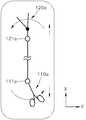
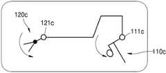
도 1e는 본 발명에 따른 수술용 인스트루먼트의 피치 동작 개념도이고, 도 1f는 요 동작 개념도이다.
도 2는 본 발명의 제1 실시예에 따른 수술용 인스트루먼트를 나타내는 사시도이다.
도 3은 도 2의 수술용 인스트루먼트의 측면도이다
도 4 및 도 5는 도 2의 수술용 인스트루먼트의 엔드 툴을 나타내는 사시도이다.
도 6a는 도 2의 수술용 인스트루먼트의 엔드 툴을 나타내는 평면도이다.
도 6b는 종래의 수술용 인스트루먼트의 엔드 툴을 나타내는 평면도이다.
도 6c는 도 6a의 엔드 툴의 일 변형예를 나타내는 도면이다.
도 6d는 도 6a의 엔드 툴의 일 변형예를 나타내는 도면이다.
도 7a 및 도 7b는 도 2의 수술용 인스트루먼트의 조작부를 나타내는 사시도이다.
도 8은 도 7에 도시된 본 발명의 일 실시예에 따른 수술용 인스트루먼트의 관절을 구성하는 풀리 및 와이어의 구성만을 간략하게 도시한 도면이다.
도 9는 도 7에 도시된 본 발명의 일 실시예에 따른 수술용 인스트루먼트의 액츄에이션 동작 및 요 동작과 관련된 풀리 및 와이어의 구성을 제1 조와 제2 조 각각에 대해 풀어서 도시한 그림이다.
도 10은 도 7의 수술용 인스트루먼트의 요 동작을 나타내는 사시도이다.
도 11은 도 7에 도시된 본 발명의 일 실시예에 따른 수술용 인스트루먼트의 피치 동작과 관련된 풀리 및 와이어의 구성을 제1 조와 제2 조 각각에 대해 풀어서 도시한 그림이다.
도 12는 도 7의 수술용 인스트루먼트의 피치 동작을 나타내는 사시도이다.
도 13은 요 관절의 직접형 관절의 일 예를 나타내는 도면이다.
도 14는 요 관절의 간접형 관절의 일 예를 나타내는 도면이다.
도 15는 피치 관절의 간접형 관절의 일 예를 나타내는 도면이다.
도 16은 피치 관절의 직접형 관절의 일 예를 나타내는 도면이다.
도 17은 도 9에 도시된 본 발명의 일 실시예에 따른 수술용 인스트루먼트의 제1 조의 동작과 관련된 풀리 및 와이어의 구성과 그 변형예들을 도시한 그림이다.
도 18은 도 17에 개시된 실시예의 다른 일 변형예를 나타내는 도면이다.
도 19는 도 17에 개시된 실시예의 다른 일 변형예를 나타내는 도면이다.
도 20은 도 17에 개시된 실시예의 다른 일 변형예를 나타내는 도면이다.
도 21은 도 17에 개시된 실시예의 다른 일 변형예를 나타내는 도면이다.
도 22는 도 17에 개시된 실시예의 다른 일 변형예를 나타내는 도면이다.
도 23은 도 17에 개시된 실시예의 다른 일 변형예를 나타내는 도면이다.
도 24는 도 17에 개시된 실시예의 다른 일 변형예를 나타내는 도면이다.
도 25는 도 17에 개시된 실시예의 다른 일 변형예를 나타내는 도면이다.
도 26은 도 17에 개시된 실시예의 다른 일 변형예를 나타내는 도면이다.
도 27은 도 17에 개시된 실시예의 다른 일 변형예를 나타내는 도면이다.
도 28은 도 8에 개시된 실시예의 다른 일 변형예를 나타내는 도면이다.
도 29는 도 16에 개시된 실시예의 다른 일 변형예를 나타내는 도면이다.
도 30 및 도 31은 절연과 관련된 일 변형예를 나타내는 도면이다.
도 32는 본 발명의 제2 실시예에 따른 수술용 인스트루먼트를 나타내는 사시도이다.
도 33은 도 32의 수술용 인스트루먼트의 내부 사시도이다.
도 34는 도 33의 수술용 인스트루먼트의 측면도이다.
도 35 및 도 36은 도 33의 수술용 인스트루먼트의 조작부를 나타내는 사시도이다.
도 37 및 도 38은 도 33의 수술용 인스트루먼트의 요 동작을 나타내는 사시도이다.
도 39 및 도 40은 도 33의 수술용 인스트루먼트의 액츄에이션 동작을 나타내는 사시도이다.
도 41은 본 발명의 제3 실시예에 따른 수술용 인스트루먼트를 나타내는 사시도이다.
도 42는 도 41의 수술용 인스트루먼트의 측면도이다.
도 43은 도 42의 수술용 인스트루먼트의 조작부를 나타내는 사시도이다.
도 44 및 도 45는 도 41의 수술용 인스트루먼트의 요 동작을 나타내는 사시도이다.
도 46 및 도 47은 도 41의 수술용 인스트루먼트의 액츄에이션 동작을 나타내는 사시도이다.
도 48은 본 발명의 제4 실시예에 따른 수술용 인스트루먼트의 요 동작을 나타내는 사시도이다.
도 49는 본 발명의 제4 실시예에 따른 수술용 인스트루먼트의 액츄에이션 동작을 나타내는 도면이다.
도 50은 본 발명의 제5 실시예에 따른 수술용 인스트루먼트를 나타내는 사시도이다.
도 51은 도 50의 수술용 인스트루먼트의 측면도이다.
도 52 및 도 53은 도 51의 수술용 인스트루먼트의 조작부를 나타내는 사시도이다.
도 54 및 도 55는 도 50의 수술용 인스트루먼트의 요 동작을 나타내는 사시도이다.
도 56는 본 발명의 제6 실시예에 따른 수술용 인스트루먼트를 나타내는 사시도이다.
도 57은 도 56의 수술용 인스트루먼트의 조작부를 나타내는 사시도이다.
도 58은 도 56의 수술용 인스트루먼트의 와이어링 구조를 나타내는 내부 사시도이다.
도 59는 도 56의 수술용 인스트루먼트의 요 동작을 나타내는 사시도이다.
도 60은 도 56의 수술용 인스트루먼트의 피치 동작을 나타내는 사시도이다.
도 61은 본 발명의 제7 실시예에 따른 수술용 인스트루먼트를 나타내는 사시도이다.
도 62는 도 61의 수술용 인스트루먼트의 측면도이다.
도 63 및 도 64는 도 61의 수술용 인스트루먼트의 조작부를 나타내는 사시도이다.
도 65는 도 61의 수술용 인스트루먼트의 내부 사시도로써 와이어링 구조를 나타내는 내부 사시도이다.
도 66은 도 65의 A 부분의 확대도이다.
도 67는 도 66의 C-C' 선을 따라 절개한 단면도이다.
도 68은 도 61의 수술용 인스트루먼트의 요 동작을 나타내는 사시도이다.
도 69는 도 61의 수술용 인스트루먼트의 피치 동작을 나타내는 사시도이다.
도 70는 본 발명의 제8 실시예에 따른 수술용 인스트루먼트를 나타내는 사시도이다.
도 71은 도 70의 수술용 인스트루먼트의 조작부를 나타내는 사시도이다.
도 72는 도 70의 수술용 인스트루먼트의 내부 사시도로써 와이어링 구조를 나타내는 내부 사시도이다.
도 73은 도 70의 수술용 인스트루먼트의 요 동작을 나타내는 사시도이다.
도 74, 75 및 76은 도 70의 수술용 인스트루먼트의 피치 동작을 나타내는 사시도이다.
도 77은 본 발명의 제9 실시예에 따른 수술용 인스트루먼트의 내부 사시도이다.
도 78은 도 77의 수술용 인스트루먼트의 요 동작을 나타내는 사시도이다.
도 79는 도 77의 수술용 인스트루먼트의 피치 동작을 나타내는 사시도이다.
도 80은 본 발명의 제10 실시예에 따른 수술용 인스트루먼트의 내부 사시도이다.
도 81은 도 80에서 액츄에이션 기어를 제거한 내부 사시도이다.
도 82는 도 81의 수술용 인스트루먼트의 요 동작을 나타내는 사시도이다.
도 83은 도 81의 수술용 인스트루먼트의 피치 동작을 나타내는 사시도이다.
도 84는 본 발명의 제11 실시예에 따른 수술용 인스트루먼트의 내부 사시도이다.
도 85는 도 84에서 액츄에이션 기어를 제거한 내부 사시도이다.
도 86은 도 84의 수술용 인스트루먼트의 요 동작을 나타내는 사시도이다.
도 87은 도 84의 수술용 인스트루먼트의 피치 동작을 나타내는 사시도이다.
도 88은 본 발명의 제12 실시예에 따른 수술용 인스트루먼트를 나타내는 사시도이다.
도 89는 도 88의 수술용 인스트루먼트의 와이어 등의 구조를 나타내는 내부 사시도이다.1A is a conceptual diagram of a pitch operation of a conventional surgical instrument, and FIG. 1B is a conceptual diagram of a yaw operation.
1C is a conceptual diagram of a pitch operation of another conventional surgical instrument, and FIG. 1D is a conceptual diagram of a yaw operation.
Figure 1e is a conceptual diagram of a pitch operation of the instrument for surgery according to the present invention, Figure 1f is a conceptual diagram of yaw operation.
Figure 2 is a perspective view showing a surgical instrument according to the first embodiment of the present invention.
Figure 3 is a side view of the surgical instrument of Figure 2
4 and 5 are perspective views illustrating an end tool of the surgical instrument of FIG. 2.
6A is a plan view showing an end tool of the surgical instrument of FIG. 2.
6B is a plan view showing an end tool of a conventional surgical instrument.
6C is a diagram illustrating a modified example of the end tool of FIG. 6A.
6D is a view showing a modified example of the end tool of FIG. 6A.
7A and 7B are perspective views illustrating an operation part of the surgical instrument of FIG. 2.
8 is a view schematically showing only the configuration of a pulley and a wire constituting the joint of the surgical instrument according to an embodiment of the present invention shown in FIG.
FIG. 9 is a diagram illustrating the configuration of pulleys and wires related to the actuation and yaw movements of the surgical instrument according to an embodiment of the present invention shown in FIG. 7 by loosening for each of
10 is a perspective view showing a yaw operation of the surgical instrument of FIG. 7.
11 is a diagram illustrating the configuration of pulleys and wires related to the pitch operation of the surgical instrument according to an embodiment of the present invention shown in FIG. 7 by loosening for each of the first and second sets.
12 is a perspective view showing a pitch operation of the surgical instrument of FIG. 7.
13 is a diagram illustrating an example of a direct joint of a yaw joint.
14 is a diagram illustrating an example of an indirect joint of a yaw joint.
15 is a diagram illustrating an example of an indirect joint of a pitch joint.
16 is a diagram illustrating an example of a direct joint of a pitch joint.
FIG. 17 is a diagram showing a configuration of a pulley and a wire related to the operation of the first set of the surgical instrument according to an embodiment of the present invention shown in FIG. 9 and modifications thereof.
18 is a diagram illustrating another modified example of the embodiment disclosed in FIG. 17.
19 is a view showing another modified example of the embodiment disclosed in FIG. 17.
20 is a view showing another modified example of the embodiment disclosed in FIG. 17.
21 is a view showing another modified example of the embodiment disclosed in FIG. 17.
22 is a diagram illustrating another modified example of the embodiment disclosed in FIG. 17.
23 is a diagram illustrating another modified example of the embodiment disclosed in FIG. 17.
24 is a view showing another modified example of the embodiment disclosed in FIG. 17.
25 is a view showing another modified example of the embodiment disclosed in FIG. 17.
26 is a diagram illustrating another modified example of the embodiment disclosed in FIG. 17.
27 is a view showing another modified example of the embodiment disclosed in FIG. 17.
28 is a diagram showing another modified example of the embodiment disclosed in FIG. 8.
29 is a view showing another modified example of the embodiment disclosed in FIG. 16.
30 and 31 are diagrams illustrating a modified example related to insulation.
32 is a perspective view showing a surgical instrument according to a second embodiment of the present invention.
33 is an internal perspective view of the surgical instrument of FIG. 32.
34 is a side view of the surgical instrument of FIG. 33.
35 and 36 are perspective views illustrating an operation part of the surgical instrument of FIG. 33.
37 and 38 are perspective views illustrating the yaw operation of the surgical instrument of FIG. 33.
39 and 40 are perspective views illustrating an actuation operation of the surgical instrument of FIG. 33.
41 is a perspective view showing a surgical instrument according to a third embodiment of the present invention.
42 is a side view of the surgical instrument of FIG. 41.
43 is a perspective view illustrating an operation part of the surgical instrument of FIG. 42.
44 and 45 are perspective views showing the yaw operation of the surgical instrument of FIG. 41.
46 and 47 are perspective views illustrating an actuation operation of the surgical instrument of FIG. 41.
48 is a perspective view showing the yaw motion of the surgical instrument according to the fourth embodiment of the present invention.
49 is a view showing an actuation operation of a surgical instrument according to a fourth embodiment of the present invention.
50 is a perspective view showing a surgical instrument according to a fifth embodiment of the present invention.
51 is a side view of the surgical instrument of FIG. 50.
52 and 53 are perspective views illustrating an operation part of the surgical instrument of FIG. 51.
54 and 55 are perspective views illustrating the yaw motion of the surgical instrument of FIG. 50.
56 is a perspective view showing a surgical instrument according to a sixth embodiment of the present invention.
57 is a perspective view showing an operation part of the surgical instrument of FIG. 56;
58 is an internal perspective view showing the wiring structure of the surgical instrument of FIG. 56.
59 is a perspective view showing a yaw operation of the surgical instrument of FIG. 56.
Figure 60 is a perspective view showing the pitch operation of the surgical instrument of Figure 56.
61 is a perspective view showing a surgical instrument according to a seventh embodiment of the present invention.
62 is a side view of the surgical instrument of FIG. 61;
63 and 64 are perspective views illustrating an operation part of the surgical instrument of FIG. 61.
Figure 65 is an internal perspective view showing the wiring structure as an internal perspective view of the surgical instrument of Figure 61.
66 is an enlarged view of portion A of FIG. 65.
67 is a cross-sectional view taken along line CC' of FIG. 66;
68 is a perspective view showing a yaw operation of the surgical instrument of FIG. 61.
69 is a perspective view showing the pitch operation of the surgical instrument of FIG. 61.
70 is a perspective view showing a surgical instrument according to an eighth embodiment of the present invention.
71 is a perspective view showing an operation part of the surgical instrument of FIG. 70;
72 is an internal perspective view showing the wiring structure of the surgical instrument of FIG. 70.
73 is a perspective view showing a yaw operation of the surgical instrument of FIG. 70;
74, 75, and 76 are perspective views illustrating the pitch operation of the surgical instrument of FIG. 70.
77 is an internal perspective view of a surgical instrument according to a ninth embodiment of the present invention.
78 is a perspective view showing a yaw operation of the surgical instrument of Figure 77.
79 is a perspective view showing the pitch operation of the surgical instrument of Figure 77.
80 is an internal perspective view of a surgical instrument according to a tenth embodiment of the present invention.
81 is an inner perspective view of FIG. 80 with the actuation gear removed.
82 is a perspective view showing a yaw operation of the surgical instrument of FIG. 81;
83 is a perspective view showing a pitch operation of the surgical instrument of FIG. 81;
84 is an internal perspective view of a surgical instrument according to an eleventh embodiment of the present invention.
85 is an inner perspective view of FIG. 84 with the actuation gear removed.
86 is a perspective view showing a yaw operation of the surgical instrument of FIG. 84.
87 is a perspective view showing the pitch operation of the surgical instrument of FIG. 84.
88 is a perspective view showing a surgical instrument according to a twelfth embodiment of the present invention.
89 is an internal perspective view showing the structure of a wire, etc. of the surgical instrument of FIG. 88;
본 발명은 다양한 변환을 가할 수 있고 여러 가지 실시예를 가질 수 있는바, 특정 실시예들을 도면에 예시하고 이에 대해 상세하게 설명하고자 한다. 그러나, 이는 본 발명을 특정한 실시 형태에 대해 한정하려는 것이 아니며, 본 발명의 사상 및 기술 범위에 포함되는 모든 변환, 균등물 내지 대체물을 포함하는 것으로 이해되어야 한다. 본 발명을 설명함에 있어서 관련된 공지 기술에 대한 구체적인 설명이 본 발명의 요지를 흐릴 수 있다고 판단되는 경우 그 상세한 설명을 생략한다.Since the present invention can apply various transformations and have various embodiments, specific embodiments are illustrated in the drawings and will be described in detail. However, this is not intended to limit the present invention to a specific embodiment, it is to be understood to include all conversions, equivalents, and substitutes included in the spirit and scope of the present invention. In describing the present invention, when it is determined that a detailed description of a related known technology may obscure the subject matter of the present invention, a detailed description thereof will be omitted.
제1, 제2 등의 용어는 다양한 구성요소들을 설명하는데 사용될 수 있지만, 상기 구성요소들은 상기 용어들에 의해 한정되어서는 안 된다. 상기 용어들은 하나의 구성요소를 다른 구성요소로부터 구별하는 목적으로만 사용된다.Terms such as first and second may be used to describe various components, but the components should not be limited by the terms. These terms are used only for the purpose of distinguishing one component from another component.
본 출원에서 사용한 용어는 단지 특정한 실시예를 설명하기 위해 사용된 것으로, 본 발명을 한정하려는 의도가 아니다. 단수의 표현은 문맥상 명백하게 다르게 뜻하지 않는 한, 복수의 표현을 포함한다. 본 출원에서, "포함하다" 또는 "가지다" 등의 용어는 명세서상에 기재된 특징, 숫자, 단계, 동작, 구성요소, 부품 또는 이들을 조합한 것이 존재함을 지정하려는 것이지, 하나 또는 그 이상의 다른 특징들이나 숫자, 단계, 동작, 구성요소, 부품 또는 이들을 조합한 것들의 존재 또는 부가 가능성을 미리 배제하지 않는 것으로 이해되어야 한다.The terms used in the present application are only used to describe specific embodiments, and are not intended to limit the present invention. Singular expressions include plural expressions unless the context clearly indicates otherwise. In the present application, terms such as "comprise" or "have" are intended to designate the presence of features, numbers, steps, actions, components, parts, or combinations thereof described in the specification, but one or more other features. It is to be understood that the presence or addition of elements or numbers, steps, actions, components, parts, or combinations thereof does not preclude in advance.
이하, 본 발명의 실시예를 첨부한 도면들을 참조하여 상세히 설명하기로 하며, 첨부 도면을 참조하여 설명함에 있어, 동일하거나 대응하는 구성 요소는 동일한 도면번호를 부여하고 이에 대한 중복되는 설명은 생략하기로 한다.Hereinafter, embodiments of the present invention will be described in detail with reference to the accompanying drawings, and in the description with reference to the accompanying drawings, the same or corresponding constituent elements are assigned the same reference numbers, and redundant descriptions thereof will be omitted. To
또한, 본 발명의 다양한 실시예들을 설명함에 있어, 각 실시예가 독립적으로 해석되거나 실시되어야 하는 것은 아니며, 각 실시예에서 설명되는 기술적 사상들이 개별적으로 설명되는 다른 실시예에 조합되어 해석되거나 실시될 수 있는 것으로 이해되어야 한다.
In addition, in describing various embodiments of the present invention, each embodiment does not have to be independently interpreted or implemented, and technical ideas described in each embodiment may be interpreted or implemented in combination with other embodiments that are individually described. It should be understood as being.
<수술용<For surgery인스트루먼트의Instrumental 제1 First실시예Example>>
본 발명에 따른 수술용 인스트루먼트는 피치, 요, 액츄에이션 동작 중 적어도 어느 하나 이상의 동작에 대해서, 조작부를 어느 일 방향으로 회전시키면, 엔드 툴이 조작부의 조작 방향과 직관적으로 동일한 방향으로 회전하는 것을 일 특징으로 한다. In the surgical instrument according to the present invention, when the operation unit is rotated in any one direction for at least one of pitch, yaw, and actuation movements, the end tool is intuitively rotated in the same direction as the operation direction of the operation unit. It is characterized.
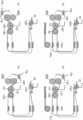
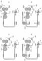
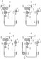
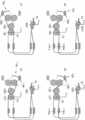
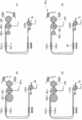
도 1a는 종래의 수술용 인스트루먼트의 피치 동작 개념도이고, 도 1b는 요 동작 개념도이다.1A is a conceptual diagram of a pitch operation of a conventional surgical instrument, and FIG. 1B is a conceptual diagram of a yaw operation.
도 1a를 참조하면, 종래의 수술용 인스트루먼트의 피치 동작을 수행함에 있어, 엔드 툴(120a)은 엔드 툴의 회전 중심(121a)보다 앞쪽에 형성되고, 조작부(110a)는 조작부의 회전 중심(111a)보다 뒤쪽에 형성된 상태에서, 조작부(110a)를 시계 방향으로 회전시키면 엔드 툴(120a) 또한 시계 방향으로 회전하고, 조작부(120a)를 반시계 방향으로 회전시키면 엔드 툴(120a) 또한 반시계 방향으로 회전하도록 형성된다. 한편, 도 1b를 참조하면, 종래의 수술용 인스트루먼트의 요 동작을 수행함에 있어, 엔드 툴(120a)은 엔드 툴의 회전 중심(121a)보다 앞쪽에 형성되고, 조작부(110a)는 조작부의 회전 중심(111a)보다 뒤쪽에 형성된 상태에서, 조작부(110a)를 시계 방향으로 회전시키면 엔드 툴(120a) 또한 시계 방향으로 회전하고, 조작부(120a)를 반시계 방향으로 회전시키면 엔드 툴(120a) 또한 반시계 방향으로 회전하도록 형성된다. 이 경우, 사용자의 좌우 방향이라는 관점에서 보았을 때, 사용자가 조작부(110a)를 왼쪽으로 움직이면 엔드 툴(120a)은 오른쪽으로 움직이고, 사용자가 조작부(110a)를 오른쪽으로 움직이면 엔드 툴(120a)은 왼쪽으로 움직이게 된다. 결과적으로, 사용자의 조작 방향과 엔드 툴의 동작 방향이 반대가 됨으로써, 사용자로 하여금 착오를 유발할 수 있고, 사용자의 조작이 용이하지 않다는 문제점이 존재하였다.Referring to Figure 1a, in performing the pitch operation of the conventional surgical instrument, the end tool (120a) is formed in front of the rotation center (121a) of the end tool, the operation unit (110a) is the rotation center (111a) of the operation unit ), when the
도 1c는 다른 종래의 수술용 인스트루먼트의 피치 동작 개념도이고, 도 1d는 요 동작 개념도이다.1C is a conceptual diagram of a pitch operation of another conventional surgical instrument, and FIG. 1D is a conceptual diagram of a yaw operation.
도 1c를 참조하면, 종래의 수술용 인스트루먼트 중 일부는 미러 대칭 형태로 형성되어, 피치 동작을 수행함에 있어, 엔드 툴(120b)은 엔드 툴의 회전 중심(121b)보다 앞쪽에 형성되고, 조작부(110b)는 조작부의 회전 중심(111b)보다 뒤쪽에 형성된 상태에서, 조작부(110b)를 시계 방향으로 회전시키면 엔드 툴(120b)은 반시계 방향으로 회전하고, 조작부(110b)를 반시계 방향으로 회전시키면 엔드 툴(120b)은 시계 방향으로 회전하도록 형성된다. 이 경우, 조작부와 엔드 툴의 회전 방향이라는 관점에서 보았을 때, 사용자가 조작부(110b)를 회전시키는 회전 방향과 그에 따른 엔드 툴(120b)의 회전 방향은 서로 반대가 된다. 결과적으로 사용자에게 조작 방향의 혼란을 가져올 수 있으며, 관절의 동작이 직관적이지 않으며, 실수를 유발할 수 있다는 문제점이 존재하였다. 또한, 도 1d를 참조하면, 요 동작을 수행함에 있어, 엔드 툴(120b)은 엔드 툴의 회전 중심(121b)보다 앞쪽에 형성되고, 조작부(110b)는 조작부의 회전 중심(111b)보다 뒤쪽에 형성된 상태에서, 조작부(110b)를 시계 방향으로 회전시키면 엔드 툴(120b)은 반시계 방향으로 회전하고, 조작부(110b)를 반시계 방향으로 회전시키면 엔드 툴(120b)은 시계 방향으로 회전하도록 형성된다. 이 경우, 조작부와 엔드 툴의 회전 방향이라는 관점에서 보았을 때, 사용자가 조작부(110b)를 회전시키는 회전 방향과 그에 따른 엔드 툴(120b)의 회전 방향은 서로 반대가 된다. 결과적으로 사용자에게 조작 방향의 혼란을 가져올 수 있으며, 관절의 동작이 직관적이지 않으며, 실수를 유발할 수 있다는 문제점이 존재하였다. 이렇게 종래의 수술용 인스트루먼트의 사용자의 피치 또는 요 조작에 있어서, 사용자의 조작 방향과 엔드 툴의 동작 방향이 회전 방향의 관점 또는 좌우 방향의 관점 중 하나에 있어서는 서로 일치하지 않는다. 이는 종래의 수술용 인스트루먼트의 관절 구성에 있어서 엔드 툴과 조작부의 구성이 서로 다르기 때문이다. 즉, 엔드 툴은 엔드 툴의 회전 중심보다 앞쪽에 형성된 데 반해, 조작부는 조작부의 회전 중심보다 뒤쪽에 형성되기 때문이다. 이와 같은 문제점을 해결하기 위하여, 도 1e 및 도 1f에 도시된 본 발명의 일 실시예에 따른 수술용 인스트루먼트는 엔드 툴(120c)을 엔드 툴의 회전 중심(121c)보다 앞쪽에 형성하고, 조작부(110c) 또한 조작부의 회전 중심(111c)보다 앞쪽에 형성하여, 조작부(110c)와 엔드 툴(120c)의 동작이 직관적으로 일치하도록 하는 것을 일 특징으로 한다. 이러한 특성을 달리 표현하면, 도 1a, 1b, 1c 및 도 1d와 같이 조작부가 자신의 관절에 대해 사용자 쪽으로 가까워지는(즉, 엔드 툴로부터 멀어지는) 구성의 기존 예와는 달리, 도 1e 및 도 1f에 도시된 본 발명의 일 실시예에 따른 수술용 인스트루먼트는 조작 과정의 어느 한 순간 이상에서는 조작부의 적어도 일부가 자신의 관절을 기준으로 (자신의 관절보다) 엔드 툴에 더 가까워질 수 있도록 형성되는 것이다.Referring to Figure 1c, some of the conventional surgical instruments are formed in a mirror symmetrical shape, in performing the pitch operation, the end tool (120b) is formed in front of the rotation center (121b) of the end tool, the operation unit ( 110b) is formed behind the
이를 다르게 설명하면, 도 1a, 1b, 1c 및 도 1d와 같은 종래의 수술용 인스트루먼트의 경우에는 엔드 툴이 자신의 회전 중심보다 앞쪽에 위치하는데 반해 조작부는 자신의 회전 중심보다 뒤쪽에 형성되어, 앞쪽이 고정된 상태에서 뒤쪽을 움직이는 조작부의 동작을 통해 뒤쪽이 고정된 상태에서 앞쪽이 움직이는 엔드 툴을 움직이게 되므로, 구조상 직관적으로 일치하지 않는 구조이다. 이로 인해, 조작부의 조작과 엔드 툴의 동작에 있어서 좌우 방향의 관점 또는 회전 방향의 관점에 있어서 불일치가 발생하고 사용자에게 혼란을 가져올 수 있으며, 조작부의 조작을 직관적으로 신속히 수행하기 힘들게 되고 실수를 유발할 수 있다는 문제점이 존재하였다. 이에 반해 본 발명의 일 실시예에 따른 수술용 인스트루먼트는 엔드 툴과 조작부 모두 뒤쪽에 형성된 회전 중심을 기준으로 움직이기 때문에 구조상 직관적으로 동작이 서로 일치한다고 할 수 있는 것이다. 다르게 설명하면, 엔드 툴의 움직이는 부분이 뒤 쪽에 형성된 회전 중심을 기준으로 움직이는 것과 같이, 조작부의 움직이는 부분도 뒤 쪽에 형성된 해당 회전 중심을 기준으로 움직이기 때문에, 구조상 직관적으로 동작이 서로 일치한다고 할 수 있다. 이로 인해 사용자는 엔드 툴 방향의 조종을 직관적으로 신속히 수행할 수 있으며, 실수가 유발될 가능성이 현저히 줄어드는 장점이 있다. 이하에서는 이러한 기능을 가능하게 하는 구체적인 메커니즘에 대해 설명하도록 한다.
In other words, in the case of a conventional surgical instrument such as FIGS. 1A, 1B, 1C, and 1D, the end tool is located in front of its rotational center, whereas the operation part is formed behind its rotational center. In this fixed state, through the operation of the operation unit that moves the rear side, the end tool moves in the front side while the rear side is fixed, so the structure is intuitively inconsistent. As a result, inconsistency may occur in the perspective of the left or right direction or the perspective of the rotation direction in the operation of the operation part and the operation of the end tool, and confusion may be caused to the user. There was a problem that it could be. On the other hand, in the surgical instrument according to an embodiment of the present invention, since both the end tool and the operation unit move based on the rotation center formed at the rear, it can be said that the motions are intuitively coincident with each other due to the structure. In other words, just as the moving part of the end tool moves based on the rotation center formed on the back side, the moving part of the operation part also moves based on the rotation center formed on the back side, so it can be said that the motions are intuitively consistent with each other due to the structure. have. Accordingly, the user can intuitively and quickly perform the control in the direction of the end tool, and the possibility of causing a mistake is significantly reduced. Hereinafter, a specific mechanism for enabling this function will be described.
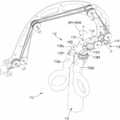
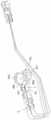
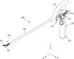
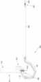
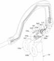
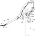
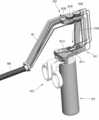
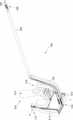
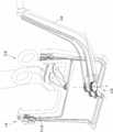
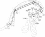
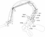
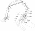
도 2는 본 발명의 제1 실시예에 따른 수술용 인스트루먼트를 나타내는 사시도이고, 도 3은 도 2의 수술용 인스트루먼트의 측면도이다.2 is a perspective view showing a surgical instrument according to a first embodiment of the present invention, and FIG. 3 is a side view of the surgical instrument of FIG. 2.
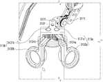
도 2 및 도 3을 참조하면, 본 발명의 제1 실시예에 따른 수술용 인스트루먼트(100)는 조작부(110), 엔드 툴(end tool)(120), 동력 전달부(130) 및 연결부(140)를 포함한다. 여기서, 연결부(140)는 속이 빈 샤프트(shaft) 형상으로 형성되어, 그 내부에 하나 이상의 와이어(후술함) 들이 수용될 수 있으며, 그 일 단부에는 조작부(110)가 결합되고, 타 단부에는 엔드 툴(120)이 결합되어, 조작부(110)와 엔드 툴(end tool)(120)을 연결하는 역할을 수행할 수 있다. 여기서, 본 발명의 제1 실시예에 따른 수술용 인스트루먼트(100)의 연결부(140)는 조작부(110) 측에 절곡부(141)가 형성되어 있는 것을 일 특징으로 한다. 이와 같이 연결부(140)의 조작부(110) 측 단부가 절곡되어 형성됨으로써, 피치 조작부(111)와 요 조작부(112)와 액츄에이션 조작부(113)가 엔드 툴(120)의 연장선상에 형성되거나 또는 연장선에 인접하게 형성된다. 이를 다른 측면으로 표현하면, 절곡부(141)가 형성하는 오목부 내에 피치 조작부(111) 및 요 조작부(112)의 적어도 일부가 수용된다고 기술할 수도 있을 것이다. 이와 같은 절곡부(141)의 형상에 의해 조작부(110)와 엔드 툴(120)의 형상 및 동작이 더욱 직관적으로 일치할 수 있다.2 and 3, the
한편, 절곡부(141)가 형성되는 평면은 피치 평면, 즉 도 2의 XZ 평면과 실질적으로 동일한 평면일 수 있다. 이와 같이, 절곡부(141)가 XZ 평면과 실질적으로 동일한 평면 상에 형성됨으로써 조작부 간의 간섭이 감소할 수 있다. 물론, 엔드 툴과 조작부의 직관적인 동작을 위해, XZ 평면 뿐만 아니라 다른 형태의 구성도 가능할 것이다.Meanwhile, the plane in which the
조작부(110)는 연결부(140)의 일 단부에 형성되며, 의사가 직접 조종할 수 있는 인터페이스, 예를 들면, 집게 형상, 스틱 형상, 레버 형상 등으로 구비되며, 이를 의사가 조종하면, 해당 인터페이스에 연결되며 수술 환자의 체내로 삽입되는 엔드 툴(120)이 소정의 작동을 함으로써 수술을 수행하게 된다. 여기서, 도 2에는 조작부(110)가 손가락을 끼운 상태에서 회전시킬 수 있는 손잡이 형상으로 형성되는 것으로 도시되어 있지만, 본 발명의 사상은 이에 제한되지 아니하며, 엔드 툴(120)과 연결되어 엔드 툴(120)을 조작할 수 있는 다양한 형태의 조작부가 가능하다 할 것이다.The
엔드 툴(120)은 연결부(140)의 타 단부에 형성되며, 수술 부위에 삽입되어 수술에 필요한 동작을 수행한다. 이와 같은 엔드 툴(120)의 일 예로써, 도 2에 도시된 바와 같이 그립(grip) 동작을 수행하기 위한 한 쌍의 조(jaw)(121)(122)가 사용될 수 있다. 다만 본 발명의 사상은 이에 제한되지 아니하며, 수술을 위한 다양한 장치들이 엔드 툴(120)로 사용될 수 있을 것이다. 예를 들어, 외팔이 소작기와 같은 구성도 엔드 툴로써 사용될 수 있을 것이다. 이와 같은 엔드 툴(120)은 조작부(110)와 동력 전달부(130)에 의해 연결되어, 조작부(110)의 구동력을 동력 전달부(130)를 통해 전달받음으로써, 그립(grip), 절단(cutting), 봉합(suturing) 동작 등 수술에 필요한 동작을 수행하게 된다.The
여기서, 본 발명의 제1 실시예에 따른 수술용 인스트루먼트(100)의 엔드 툴(120)은 적어도 두 개 이상의 방향으로 회전가능하도록 형성되며, 예를 들어 엔드 툴(120)은 도 2의 Y축을 중심으로 피치(pitch) 운동을 수행하는 동시에, 도 2의 Z축을 중심으로 요(yaw) 운동 및 액츄에이션(actuation) 운동을 수행하도록 형성될 수 있다.Here, the
여기서, 본 발명에서 사용되는 피치(pitch)와 요(yaw)와 액츄에이션(actuation) 동작 각각에 대해 정의하면 다음과 같다.Here, the pitch, yaw, and actuation operations used in the present invention will be defined as follows.
먼저, 피치(pitch) 동작은 엔드 툴(120)이 연결부(140)의 연장 방향(도 2의 X축 방향)에 대해서 상하 방향으로 회전하는 운동, 즉 도 2의 Y축을 중심으로 회전하는 동작을 의미한다. 다시 말하면, 연결부(140)의 연장 방향(도 2의 X축 방향)으로 연결부(140)로부터 연장형성되어 있는 엔드 툴(120)이 연결부(140)에 대해 Y축을 중심으로 상하로 회전하는 운동을 의미한다. 다음으로, 요(yaw) 동작은 엔드 툴(120)이 연결부(140)의 연장 방향(도 2의 X축 방향)에 대해서 좌우 방향으로 회전하는 동작, 즉 도 2의 Z축을 중심으로 회전하는 동작을 의미한다. 다시 말하면, 연결부(140)의 연장 방향(도 2의 X축 방향)으로 연결부(140)로부터 연장형성되어 있는 엔드 툴(120)이 연결부(140)에 대해 Z축을 중심으로 좌우로 회전하는 운동을 의미한다. 즉, 엔드 툴(120)에 형성된 두 개의 조(jaw)(121)(122)가 Z축을 중심으로 서로 동일한 방향으로 회전하는 운동을 의미한다. 한편, 액츄에이션(actuation) 동작은 엔드 툴(120)이 요(yaw) 동작과 동일한 회전축을 중심으로 회전하되, 두 개의 조(jaw)(121)(122)가 서로 반대 방향으로 회전하면서 조(jaw)가 오므라들거나 벌어지는 동작을 의미한다. 즉, 엔드 툴(120)에 형성된 두 개의 조(jaw)(121)(122)가 Z축을 중심으로 서로 반대 방향으로 회전하는 운동을 의미한다.First, the pitch operation refers to a movement in which the
동력 전달부(130)는 조작부(110)와 엔드 툴(120)을 연결하여, 조작부(110)의 구동력을 엔드 툴(120)에 전달하는 역할을 수행하며, 다수 개의 와이어, 풀리, 링크, 마디, 기어 등을 포함할 수 있다. 본 발명의 일 실시예에 따른 수술용 인스트루먼트(100)에서, 동력 전달부(130)는 피치 와이어(130P), 제1 조 와이어(130J1), 제2 조 와이어(130J2) 를 포함할 수 있다.The
이하에서는 도 2의 수술용 인스트루먼트(100)의 조작부(110), 엔드 툴(120), 동력 전달부(130) 등에 대해 더욱 상세히 설명하도록 한다.
Hereinafter, the
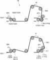
도 4 및 도 5는 도 2의 수술용 인스트루먼트의 엔드 툴을 나타내는 사시도이고, 도 6a는 도 2의 수술용 인스트루먼트의 엔드 툴을 나타내는 평면도이다.4 and 5 are perspective views illustrating an end tool of the surgical instrument of FIG. 2, and FIG. 6A is a plan view illustrating an end tool of the surgical instrument of FIG. 2.
도 4, 5 및 도 6a를 참조하면, 본 발명의 제1 실시예의 엔드 툴(end tool)(120)은 그립(grip) 동작을 수행하기 위한 한 쌍의 조(jaw)(121)(122), 즉 제1 조(121)와 제2 조(122)를 구비한다. 또한, 엔드 툴(120)은 제1 조(jaw)(121)의 회전 운동과 관련된 J11 풀리(123J11), J12 풀리(123J12), J13 풀리(123J13), J14 풀리(123J14) 및 J15 풀리(123J15)와, 제2 조(jaw)(122)의 회전 운동과 관련된 J21 풀리(123J21), J22 풀리(123J22), J23 풀리(123J23), J24 풀리(123J24), J25 풀리(123J25)를 포함한다. 여기서, 제1 조(121), J11 풀리(123J11), J12 풀리(123J12), J14 풀리(123J14), 제2 조(122), J21 풀리(123J21), J22 풀리(123J22), J24 풀리(123J24)는 모두 엔드 툴 피치 회전축(123PA)을 중심으로 회전하도록 형성될 수 있다.4, 5 and 6A, the
한편, 엔드 툴(120)과 결합하는 연결부(140)의 일 단부에는 연결부 허브(142)가 형성된다. 그리고, 상술한 J12 풀리(123J12), J13 풀리(123J13), J14 풀리(123J14), J15 풀리(123J15)와, J22 풀리(123J22), J23 풀리(123J23), J24 풀리(123J24), J25 풀리(123J25)는 연결부 허브(142)에 연결된다.On the other hand, a
여기서, 도면에는 마주보고 있는 풀리들이 서로 평행하게 형성되는 것으로 도시되어 있으나, 본 발명의 사상은 이에 제한되지 아니하며, 각각의 풀리들이 엔드 툴의 구성에 적합한 위치 및 크기로 다양하게 형성될 수 있다 할 것이다.Here, although the drawing shows that the pulleys facing each other are formed parallel to each other, the spirit of the present invention is not limited thereto, and each pulley may be variously formed in a position and size suitable for the configuration of the end tool. will be.
J11 풀리(123J11) 및 J21 풀리(123J21)는 서로 마주보도록 형성되며, 조 회전축(123JA)을 중심으로 서로 독립적으로 회전가능하도록 형성된다. 여기서, J11 풀리(123J11)에는 제1 조(jaw)(121)가 고정결합되어서 J11 풀리(123J11)와 함께 회전하며, J21 풀리(123J21)에는 제2 조(jaw)(122)가 고정결합되어서 J21 풀리(123J21)와 함께 회전할 수 있다. J11 풀리(123J11) 및 J21 풀리(123J21)의 회전에 따라 엔드 툴(end tool)(120)의 요 동작 및 액츄에이션 동작이 수행된다. 즉, J11 풀리(123J11) 및 J21 풀리(123J21)가 같은 방향으로 회전하면 요 동작이 수행되는 것이고, J11 풀리(123J11) 및 J21 풀리(123J21)가 서로 반대 방향으로 회전하면 액츄에이션 동작이 수행되는 것이다.The J11 pulley (123J11) and the J21 pulley (123J21) are formed to face each other, and are formed to be rotatable independently of each other around the jaw rotation shaft (123JA). Here, the first jaw (121) is fixedly coupled to the J11 pulley (123J11) and rotates with the J11 pulley (123J11), and the second jaw (122) is fixedly coupled to the J21 pulley (123J21). It can rotate with the J21 pulley (123J21). According to the rotation of the J11 pulley (123J11) and J21 pulley (123J21), the yaw operation and actuation operation of the
한편, J11 풀리(123J11) 및 J21 풀리(123J21)의 일 측에는 보조 풀리인 J16 풀리(123J16) 및 J26 풀리(123J26)가 추가로 구비될 수 있으며, 이와 같은 보조 풀리들은 보조 출리 축(123S)을 중심으로 회전 가능하도록 형성될 수 있다. 여기서 도면에는 J16 풀리(123J16) 및 J26 풀리(123J26)가 하나의 보조 출리 축(123S)을 중심으로 회전하는 것으로 형성되어 있으나, 각각의 보조 풀리가 별도의 축을 중심으로 회전가능하도록 형성될 수 있음은 물론이다. 다시 말하면, 보조 풀리인 J16 풀리(123J16)는 J11 풀리(123J11)와 J12 풀리(123J12)/J14 풀리(123J14)의 사이에 배치될 수 있다. 또한, 보조 풀리인 J26 풀리(123J26)는 J21 풀리(123J21)와 J22 풀리(123J22)/J24 풀리(123J24)의 사이에 배치될 수 있다. 이와 같은 보조 풀리에 대해서는 뒤에서 보다 상세히 설명하도록 한다.Meanwhile, on one side of the J11 pulley (123J11) and J21 pulley (123J21), auxiliary pulleys J16 pulley (123J16) and J26 pulley (123J26) may be additionally provided, and such auxiliary pulleys have an auxiliary pulley shaft (123S). It may be formed to be rotatable about the center. Here, in the drawing, the J16 pulley (123J16) and the J26 pulley (123J26) are formed to rotate around one auxiliary pulley shaft (123S), but each auxiliary pulley may be formed to be rotatable around a separate axis. Of course. In other words, the auxiliary pulley J16 pulley (123J16) may be disposed between the J11 pulley (123J11) and the J12 pulley (123J12) / J14 pulley (123J14). In addition, the auxiliary pulley J26 pulley (123J26) may be disposed between the J21 pulley (123J21) and the J22 pulley (123J22) / J24 pulley (123J24). This auxiliary pulley will be described in more detail later.
이하에서는 J11 풀리(123J11)의 회전과 관련된 구성 요소들을 설명한다.Hereinafter, components related to the rotation of the J11 pulley 123J11 will be described.
J11 풀리(123J11)의 일 측에는, 서로 마주보도록 J12 풀리(123J12) 및 J14 풀리(123J14)가 배치된다. 여기서, J12 풀리(123J12) 및 J14 풀리(123J14)는 엔드 툴 피치 회전축(123PA)을 중심으로 서로 독립적으로 회전가능하도록 형성된다. 또한, J12 풀리(123J12) 및 J14 풀리(123J14) 각각의 일 측에는, 서로 마주보도록 J13 풀리(123J13) 및 J15 풀리(123J15)가 배치된다. 여기서, J13 풀리(123J13) 및 J15 풀리(123J15)는 Y축 방향을 중심으로 서로 독립적으로 회전가능하도록 형성된다. 여기서, 도면에는 J12 풀리(123J12), J13 풀리(123J13), J14 풀리(123J14) 및 J15 풀리(123J15)가 모두 Y축 방향을 중심으로 회전가능하도록 형성되는 것으로 도시되어 있으나, 본 발명의 사상은 이에 제한되지 아니하며, 각 풀리의 회전축들은 그 구성에 적절하도록 다양한 방향으로 형성될 수 있을 것이다.On one side of the J11 pulley (123J11), a J12 pulley (123J12) and a J14 pulley (123J14) are disposed to face each other. Here, the J12 pulley (123J12) and the J14 pulley (123J14) are formed to be rotatable independently of each other around the end tool pitch rotation shaft (123PA). Further, on one side of each of the J12 pulleys 123J12 and the J14 pulleys 123J14, the J13 pulleys 123J13 and the J15 pulleys 123J15 are disposed to face each other. Here, the J13 pulley (123J13) and the J15 pulley (123J15) are formed to be rotatable independently of each other around the Y-axis direction. Here, in the drawings, J12 pulley (123J12), J13 pulley (123J13), J14 pulley (123J14) and J15 pulley (123J15) are all shown to be rotatable around the Y-axis direction, but the spirit of the present invention The present invention is not limited thereto, and the rotation shafts of each pulley may be formed in various directions to suit the configuration.
제1 조 와이어(130J1)는 J13 풀리(123J13), J12 풀리(123J12), J11 풀리(123J11), J16 풀리(123J16), J14 풀리(123J14), J15 풀리(123J15)와 적어도 일부가 접촉하도록 차례로 감기며, 제1 조 와이어(130J1)가 상기 풀리들을 회전시키면서 상기 풀리들을 따라서 이동할 수 있도록 형성된다.
따라서, 제1 조 와이어(130J1)가 도 6a의 화살표 J1R 쪽으로 당겨지면, 제1 조 와이어(130J1)가 J15 풀리(123J15), J14 풀리(123J14), J16 풀리(123J16), J11 풀리(123J11), J12 풀리(123J12), J13 풀리(123J13)를 회전시키게 되며, 이때 J11 풀리(123J11)가 도 6a의 화살표 R 방향으로 회전하면서 제1 조(jaw)(121)를 함께 회전시킨다.Therefore, when the first wire (130J1) is pulled toward the arrow J1R of FIG. 6A, the first wire (130J1) is a J15 pulley (123J15), J14 pulley (123J14), J16 pulley (123J16), J11 pulley (123J11). , The J12 pulley (123J12), the J13 pulley (123J13) is rotated, and at this time, the J11 pulley (123J11) rotates in the direction of the arrow R of FIG. 6A and rotates the first jaw (121) together.
반대로, 제1 조 와이어(130J1)가 도 6a의 화살표 J1L 쪽으로 당겨지면, 제1 조 와이어(130J1)가 J13 풀리(123J13), J12 풀리(123J12), J11 풀리(123J11), J16 풀리(123J16), J14 풀리(123J14), J15 풀리(123J15)를 회전시키게 되며, 이때 J11 풀리(123J11)가 도 6a의 화살표 L 방향으로 회전하면서 제1 조(jaw)(121)를 함께 회전시킨다.
On the contrary, when the first wire (130J1) is pulled toward the arrow J1L of FIG. 6A, the first wire (130J1) is pulled J13 (123J13), pulley (123J12) J11, pulley (123J11), J16 pulley (123J16). , The J14 pulley (123J14), the J15 pulley (123J15) is rotated, and at this time, the J11 pulley (123J11) rotates in the direction of the arrow L of FIG. 6A and rotates the first jaw (121) together.
이하에서는 보조 풀리(123J16, 123J26)에 대해 보다 상세히 설명하도록 한다.Hereinafter, the auxiliary pulleys 123J16 and 123J26 will be described in more detail.
보조 풀리(123J16, 123J26)는 제1 조 와이어(130J1) 및 제2 조 와이어(130J2)와 접촉하여 제1 조 와이어(130J1) 및 제2 조 와이어(130J2)의 배치 경로를 일정 정도 변경해줌으로써, 제1 조(121) 및 제2 조(122) 각각의 회전 반경을 확대시키는 역할을 수행할 수 있다. 즉, 도 6b와 같이 보조 풀리가 배치되지 않을 경우, 제1 조(121) 및 제2 조(122) 각각은 직각까지만 회전할 수 있었으나, 본 발명의 일 실시예에서는 보조 풀리(123J16, 123J26)를 추가로 구비함으로써, 도 6a에서 보았을 때 θ만큼 최대 회전 각도가 커지는 효과를 얻을 수 있다. 이는 엔드 툴(120)의 두 조가 L 방향으로 90° 만큼 함께 요 회전한 상태에서, 액츄에이션 동작을 위해 두 조가 벌어져야 하는 동작을 가능하게 해준다. 즉, 제2 조(122)가 도 6a에서처럼 추가적인 각도(θ)만큼 회전할 수 있기 때문이다. 마찬가지로, 두 조가 R 방향으로 요 회전한 상태에서도 액츄에이션 동작이 가능하다. 다시 말하면, 보조 풀리(123J16, 123J26)의 구성을 통해, 액츄에이션 동작이 가능한 요 회전의 범위를 확대할 수 있는 특징을 가진다. 이를 더욱 상세히 설명하면 다음과 같다.The auxiliary pulleys 123J16 and 123J26 contact the
도 6b를 참조하면, 제1 조 와이어(130J1)는 J11 풀리(미도시)에 고정 결합되어 있고, 제2 조 와이어(130J2)는 J21 풀리(123J21)에 고정 결합되어 있기 때문에, 보조 풀리가 배치되지 않을 경우, J11 풀리(미도시) 및 J21 풀리(123J21) 각각은 화살표 L 방향으로는 도 6b의 M 라인까지만 회전할 수 있다. 다시 말하면, 제1 조 와이어(130J1)와 J11 풀리(123J11)의 고정 결합부와 제1 조 와이어(130J1)가 분리되지 않는 대략 직각 방향까지만 회전 가능하게 된다. 이 경우, 제1 조(121) 및 제2 조(122)가 도 6b의 M 라인에 위치한 상태에서 액츄에이션 동작을 수행하게 되면, 제1 조(121)는 R 방향으로 벌어질 수 있지만, 제2 조(122)는 L 방향으로 M 라인 이상으로는 회전할 수 없다. 따라서 제1 조(121) 및 제2 조(122)가 일정 각도 이상 요 동작을 수행하고 있는 상태에서는, 액츄에이션 동작이 원활하게 수행되지 못하는 문제점이 존재하였다.Referring to FIG. 6B, since the
이와 같은 문제점을 해결하기 위해, 본 발명의 일 실시예에 따른 수술용 인스트루먼트(100)에서는 J11 풀리(123J11) 및 J21 풀리(123J21)의 일 측에 보조 풀리인 J16 풀리(123J16) 및 J26 풀리(123J26)를 추가로 배치하는 것을 특징으로 한다. 이와 같이 J16 풀리(123J16) 및 J26 풀리(123J26)를 배치하여, 제1 조 와이어(130J1) 및 제2 조 와이어(130J2)의 배치 경로를 일정 정도 변경해줌으로써, 제1 조 와이어(130J1) 및 제2 조 와이어(130J2)의 접선 방향을 변경시키고, 따라서 제2 조 와이어(130J2)와 J21 풀리(123J21)의 고정결합부가 도 6a의 N 라인까지 회전할 수 있도록 하는 것이다. 즉, 제2 조 와이어(130J2)와 J21 풀리(123J21)의 결합부는 J21 풀리(123J21)와 J26 풀리(123J26)의 공통 내접선 상에 위치할때까지 회전 가능하게 된다. 마찬가지로, 제1 조 와이어(130J1)와 J11 풀리(123J11)의 결합부는 J11 풀리(123J11)와 J16 풀리(123J16)의 공통 내접선 상에 위치할때까지 회전 가능하게 되어, R 방향으로 회전 범위가 확대될 수 있다.In order to solve such a problem, in the
이와 같은 본 발명에 의해서, 제1 조(121) 및 제2 조(122)의 회전 반경이 넓어짐으로써, 정상적인 개폐 액츄에이션 동작이 수행될 수 있는 요 동작 범위가 넓어지는 효과를 얻을 수 있다.
According to the present invention, the rotation radius of the
다음으로, J21 풀리(123J21)의 회전과 관련된 구성 요소들을 설명한다.Next, the components related to the rotation of the J21 pulley (123J21) will be described.
J21 풀리(123J21)의 일 측에는, 서로 마주보도록 J22 풀리(123J22) 및 J24 풀리(123J24)가 배치된다. 여기서, J22 풀리(123J22) 및 J24 풀리(123J24)는 엔드 툴 피치 회전축(123PA) 방향을중심으로 서로 독립적으로 회전가능하도록 형성된다. 또한, J22 풀리(123J22) 및 J24 풀리(123J24) 각각의 일 측에는, 서로 마주보도록 J23 풀리(123J23) 및 J25 풀리(123J25)가 배치된다. 여기서, J23 풀리(123J23) 및 J15 풀리(123J25)는 Y축 방향을 중심으로 서로 독립적으로 회전가능하도록 형성된다. 여기서, 도면에는 J22 풀리(123J22), J23 풀리(123J23), J24 풀리(123J24) 및 J25 풀리(123J25)가 모두 Y축 방향을 중심으로 회전가능하도록 형성되는 것으로 도시되어 있으나, 본 발명의 사상은 이에 제한되지 아니하며, 각 풀리의 회전축들은 그 구성에 적절하도록 다양한 방향으로 형성될 수 있을 것이다.On one side of the J21 pulley (123J21), a J22 pulley (123J22) and a J24 pulley (123J24) are disposed to face each other. Here, the J22 pulley (123J22) and the J24 pulley (123J24) are formed to be independently rotatable with respect to the direction of the end tool pitch rotation shaft (123PA). Further, on one side of each of the J22 pulleys 123J22 and the J24 pulleys 123J24, the J23 pulleys 123J23 and the J25 pulleys 123J25 are disposed to face each other. Here, the J23 pulley (123J23) and the J15 pulley (123J25) are formed to be rotatable independently of each other around the Y-axis direction. Here, in the drawing, J22 pulley (123J22), J23 pulley (123J23), J24 pulley (123J24) and J25 pulley (123J25) are all shown to be rotatable about the Y-axis direction, but the idea of the present invention The present invention is not limited thereto, and the rotation shafts of each pulley may be formed in various directions to suit the configuration.
제2 조 와이어(130J2)는 J23 풀리(123J23), J22 풀리(123J22), J21 풀리(123J21), J26 풀리(123J26), J24 풀리(123J24), J25 풀리(123J25)와 적어도 일부가 접촉하도록 차례로 감기며, 제2 조 와이어(130J2)가 상기 풀리들을 회전시키면서 상기 풀리들을 따라서 이동할 수 있도록 형성된다.Article 2 wire (130J2) is the J23 pulley (123J23), J22 pulley (123J22), J21 pulley (123J21), J26 pulley (123J26), J24 pulley (123J24), J25 pulley (123J25) and at least part of the contact in order. It is wound, and the second wire (130J2) is formed to move along the pulleys while rotating the pulleys.
따라서, 제2 조 와이어(130J2)가 도 6a의 화살표 J2R 쪽으로 당겨지면, 제2 조 와이어(130J2)가 J23 풀리(123J23), J22 풀리(123J22), J21 풀리(123J21), J26 풀리(123J26), J24 풀리(123J24), J25 풀리(123J25)를 회전시키게 되며, 이때 J21 풀리(123J21)가 도 6a의 화살표 R 방향으로 회전하면서 제2 조(jaw)(122)를 함께 회전시킨다.Therefore, when the second wire (130J2) is pulled toward the arrow J2R of Figure 6a, the second wire (130J2) is pulley J23 (123J23), pulley J22 (123J22), pulley (123J21), J26 pulley (123J26) , The J24 pulley (123J24) and the J25 pulley (123J25) are rotated, and at this time, the J21 pulley (123J21) rotates in the direction of the arrow R of FIG. 6A to rotate the second jaw (122) together.
반대로, 제2 조 와이어(130J2)가 도 6a의 화살표 J2L 쪽으로 당겨지면, 제2 조 와이어(130J2)가 J25 풀리(123J25), J24 풀리(123J24), J26 풀리(123J26), J21 풀리(123J21), J22 풀리(123J22), J23 풀리(123J23)를 회전시키게 되며, 이때 J21 풀리(123J21)가 도 6a의 화살표 L 방향으로 회전하면서 제2 조(jaw)(122)를 함께 회전시킨다.On the contrary, when the second wire (130J2) is pulled toward the arrow J2L of Fig. 6A, the second wire (130J2) is pulled J25 (123J25), pulley J24 (123J24), pulley J26 (123J26), pulley (123J21). , The J22 pulley (123J22) and the J23 pulley (123J23) are rotated, and at this time, the J21 pulley (123J21) rotates in the direction of the arrow L of FIG. 6A while rotating the second jaw (122) together.
한편, 제1 조 와이어(130J1)의 일 단부는 도 6a의 화살표 J1R 쪽으로 당겨지고, 동시에 제1 조 와이어(130J1)의 타 단부는 도 6a의 화살표 J1L 쪽으로 당겨지면(즉 제1 조 와이어(130J1)의 양 단부가 모두 당겨지면), 도 5와 같이 제1 조 와이어(130J1)는 엔드 툴 피치 회전축(123PA)을 중심으로 회전할 수 있는 J12 풀리(123J12)와 J14 풀리(123J14)의 아래쪽으로 감겨있기 때문에, 제1 조 와이어(130J1)가 고정결합되어 있는 J11 풀리(123J11), 제1 조(121), 조 회전축(123JA), 엔드 툴 허브(123a) 및 이와 연결된 제2 조(122) 등은 전체적으로 엔드 툴 피치 회전축(123PA)을 중심으로 반시계 방향으로 함께 회전하게 되어, 결과적으로 엔드 툴(120)이 아래쪽으로 회전하면서 피치 운동을 수행하게 된다. 이 때, 제2 조(122) 및 이에 고정결합된 제2 조 와이어(130J2)는 엔드 툴 피치 회전축(123PA)을 중심으로 회전할 수 있는 J22 풀리(123J22)와 J24 풀리(123J24)의 위쪽으로 감겨있기 때문에, 제2 조 와이어(130J2)의 양단부는 각각 J2L, J2R의 반대방향으로 이동하게 된다.On the other hand, when one end of the
반대로, 제2 조 와이어(130J2)의 일 단부는 도 6a의 화살표 J2R 쪽으로 당겨지고, 동시에 제2 조 와이어(130J2)의 타 단부는 도 6a의 화살표 J2L 쪽으로 당겨지면, 도 5와 같이 제2 조 와이어(130J2)는 엔드 툴 피치 회전축(123PA)을 중심으로 회전할 수 있는 J22 풀리(123J22)와 J24 풀리(123J24)의 위쪽으로 감겨있기 때문에, 제2 조 와이어(130J2)가 고정결합되어 있는 J21 풀리(123J21), 제2 조(122), 조 회전축(123JA), 엔드 툴 허브(123a) 및 이와 연결된 제1 조(121) 등은 전체적으로 엔드 툴 피치 회전축(123PA)을 중심으로 시계 방향으로 함께 회전하게 되어, 결과적으로 엔드 툴(120)이 위쪽으로 회전하면서 피치 운동을 수행하게 된다. 이 때, 제1 조(121) 및 이에 고정결합된 제1 조 와이어(130J1)는 엔드 툴 피치 회전축(123PA)을 중심으로 회전할 수 있는 J12 풀리(123J12)와 J14 풀리(123J14)의 아래쪽으로 감겨있기 때문에, 제1 조 와이어(130J1)의 양단부는 각각 J1L, J1R의 반대방향으로 이동하게 된다.On the contrary, if one end of the Article 2 wire 130J2 is pulled toward the arrow J2R of FIG. 6A, and at the same time, the other end of the Article 2 wire 130J2 is pulled toward the arrow J2L of FIG. 6A, as shown in FIG. Since the wire 130J2 is wound upwards of the J22 pulley (123J22) and the J24 pulley (123J24) that can rotate around the end tool pitch rotation shaft (123PA), the second set wire (130J2) is fixedly coupled to J21. The pulley (123J21), the second jaw (122), the jaw rotation shaft (123JA), the end tool hub (123a), and the first jaw (121) connected thereto are as a whole together in a clockwise direction around the end tool pitch rotation axis (123PA). As a result, the
한편, 본 발명의 수술용 인스트루먼트(100b)의 엔드 툴(120)은 피치 풀리(123P)를 더 구비하고, 조작부(110)는 피치 와이어 엔드 풀리(115P)를 더 구비하며, 동력 전달부(130)는 피치 와이어(130P)를 더 구비할 수 있다. 상세히, 엔드 툴(120)의 피치 풀리(123P)는 엔드 툴 피치 회전축(123PA)을 중심으로 회전 가능하며 엔드 툴 허브(123a)에 고정결합되도록 형성될 수 있다. 한편, 조작부의 피치 풀리는 피치 회전축을 중심으로 회전 가능하며 피치 조작부(미도시)에 고정결합되도록 형성될 수 있다. 또한, 피치 와이어(130P)는 엔드 툴(120)의 피치 풀리(123P)와 조작부의 피치 풀리를 연결하는 역할을 수행할 수 있다.On the other hand, the
따라서 사용자가 조작부(110)의 제1 손잡이(114)를 손으로 쥐고 있는 상태에서, 피치 회전축(1111)을 중심으로 제1 손잡이(114)를 회전시키면, 제1 손잡이(114)와 결합된 피치 풀리가 피치 회전축(1111)을 중심으로 회전하며, 피치 풀리의 회전은 피치 와이어(130P)를 통해 엔드 툴(120)의 피치 풀리(123P)로 전달되어 피치 풀리(123P)도 함께 회전하게 되고, 결과적으로 엔드 툴(end tool)(120)이 회전하면서 피치 운동을 수행하게 되는 것이다.Therefore, when the user rotates the
즉, 본 발명의 제1 실시예에 따른 수술용 인스트루먼트(100)는 엔드 툴(120)의 피치 풀리(123P), 조작부(110)의 피치 와이어 엔드 풀리(115P) 및 동력 전달부(130)의 피치 와이어(130P)를 구비하여, 피치 조작부(111)의 피치 동작의 구동력이 보다 완벽하게 엔드 툴(120)에 전달되도록 함으로써, 동작 신뢰성을 향상시킬 수 있다.
That is, the
도 6c는 엔드 툴과 와이어의 결합 구조의 일 변형예를 나타내는 도면이다.6C is a view showing a modified example of the coupling structure of the end tool and the wire.
도 6c를 참조하면, J21 풀리(123J21)에 제2 조 와이어(130J2)가 결합됨에 있어서, J21 풀리(123J21)를 기준으로 제2 조 와이어(130J2)를 두 개의 와이어 제2 조 와이어R(130J2R)과 제2 조 와이어L(130J2L)로 분할한 후, 각 와이어(130J2R)(130J2L)의 한쪽 끝을 각각 J21 풀리(123J21)에 결합한다. 즉, 제2 조 와이어R(130J2R)의 일 단부는 J21 풀리(123J21)의 제1 결합부(123J21R)에 결합하고, 제2 조 와이어L(130J2L)의 일 단부는 J21 풀리(123J21)의 제2 결합부(123J21L)에 결합하게 된다.Referring to Figure 6c, in the J21 pulley (123J21) in the Article 2 wire (130J2) is coupled, based on the J21 pulley (123J21) Article 2 wire (130J2) two wires Article 2 wire R (130J2R) ) And Article 2 wire L (130J2L), and then, one end of each wire (130J2R) (130J2L) is coupled to each J21 pulley (123J21). That is, one end of the Article 2 wire R (130J2R) is coupled to the first coupling portion (123J21R) of the J21 pulley (123J21), and one end of the Article 2 wire L (130J2L) is made of the J21 pulley (123J21). 2 It is coupled to the coupling portion (123J21L).
이때, J21 풀리(123J21)의 각 결합부(123J21R, 123J21L)의 위치는 각 와이어(130J2R, 130J2L)가 서로 겹칠 수 있도록 하는 위치이다. 이를 통해, 도 6b 에서 제2 조(122)의 회전 반경이 90°로 제한되는 것을 확장시켜, 결과적으로 도 6a 와 같이 제2 조(122)의 회전 반경을 확장시킬 수 있다.At this time, the positions of the coupling portions 123J21R and 123J21L of the J21 pulley 123J21 are positions so that the wires 130J2R and 130J2L can overlap each other. Through this, it is possible to expand the limit of the rotation radius of the
제1 조 와이어(130J1)도 상기 방법과 동일하게 J11 풀리(123J11)에 고정결합되게 할 수 있으며, 결과적으로 제1 조(121)의 회전 반경을 확장시킬 수 있다. 이를 통해 정상적인 개폐 액츄에이션 동작이 수행될 수 있는 요 동작 범위가 넓어지는 효과를 가질 수 있다.
도 6d는 엔드 툴과 와이어의 결합 구조의 다른 일 변형예를 나타내는 도면이다.6D is a view showing another modified example of the coupling structure of the end tool and the wire.
도 6d를 참조하면, J11 풀리(123J11)에 제1 조 와이어(130J1)가 결합됨에 있어서, J11 풀리(123J11)를 기준으로 제1 조 와이어(130J1)를 두 개의 와이어 제1 조 와이어R(130J1R)과 제1 조 와이어L(130J1L)로 분할한 후, 각 와이어 가닥(130J1R)(130J1L)의 한쪽 끝을 각각 J11 풀리(123J11)의 결합 부재(123J11C)에 결합한다. 이때 결합 부재(123J21C)는 J11 풀리(123J11)에서 제1 조(121)의 반대 쪽에 형성되며, 결합 부재(123J21C)의 일 측에는 제1 조 와이어R(130J1R)의 일 단부가 결합되고, 결합 부재(123J21C)의 타 측에는 제1 조 와이어L(130J1L)의 일 단부가 결합된다.6D, in the J11 pulley (123J11) is coupled to the first wire (130J1), based on the J11 pulley (123J11)
이때, J11 풀리(123J11)의 결합 부재(123J21C)의 위치는 각 와이어(130J1R, 130J1L)를 반바퀴 더 감기도록 하는 위치이다. 이를 통해, 도 6b 에서 제2 조(122)의 회전 반경이 90°로 제한되는 것을 확장시켜, 결과적으로 도 6a 와 같이 제2 조(122)의 회전 반경을 확장시킬 수 있다.At this time, the position of the coupling member (123J21C) of the J11 pulley (123J11) is a position so that the respective wires (130J1R, 130J1L) to be wound half a turn. Through this, it is possible to expand the limit of the rotation radius of the
제2 조 와이어(130J2)도 상기 방법과 동일하게 J21 풀리(123J21)에 고정결합되게 할 수 있으며, 결과적으로 제2 조(122)의 회전 반경을 확장시킬 수 있다. 이를 통해 정상적인 개폐 액츄에이션 동작이 수행될 수 있는 요 동작 범위가 넓어지는 효과를 가질 수 있다.
Article 2 wire (130J2) can be fixedly coupled to the J21 pulley (123J21) in the same manner as in the above method, as a result, it is possible to expand the turning radius of the second jaw (122). Through this, the yaw motion range in which the normal opening and closing actuation operation can be performed may be widened.
(조작부)(Operation part)
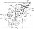
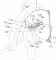
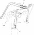
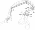
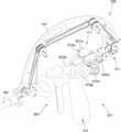
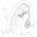
도 7(a)는 도 2의 수술용 인스트루먼트의 조작부를 나타내는 사시도이고, 도 7(b)는 도 7(a)를 뒤쪽에서 바라본 사시도이다.7(a) is a perspective view showing the operation part of the surgical instrument of FIG. 2, and FIG. 7(b) is a perspective view of FIG. 7(a) viewed from the rear.
도 2 내지 도 7을 참조하면, 본 발명의 제1 실시예에 따른 수술용 인스트루먼트(100)의 조작부(110)는 사용자가 파지할 수 있는 제1 손잡이(114)와, 엔드 툴(120)의 액츄에이션 운동을 제어하는 액츄에이션 조작부(113)와, 엔드 툴(120)의 요 운동을 제어하는 요 조작부(112)와, 엔드 툴(120)의 피치 운동을 제어하는 피치 조작부(111)를 포함한다.2 to 7, the
먼저, 도 2의 수술용 인스트루먼트(100)의 사용 상태를 예시하면, 사용자는 손바닥으로 제1 손잡이(114)를 잡고 있는 상태에서 제1 손잡이(114)를 Y축(즉, 피치 회전축(1111))을 중심으로 회전시켜 피치 동작을 수행하고, 제1 손잡이(114)를 Z축(즉, 요 회전축(1121))을 중심으로 회전시켜 요 동작을 수행할 수 있다. 또한, 사용자는 엄지 손가락과 검지 손가락을 액츄에이션 조작부(113)에 끼워 넣은 상태에서 액츄에이션 조작부(113)를 회전하여 액츄에이션 동작을 수행할 수 있다.First, when illustrating the state of use of the
여기서, 본 발명의 제1 실시예에 따른 수술용 인스트루먼트(100)는 조작부(110)를 연결부(140)에 대해 어느 일 방향으로 회전시키면, 엔드 툴(120)이 조작부(110)의 조작 방향과 직관적으로 동일한 방향으로 회전하는 것을 일 특징으로 한다. 다시 말하면, 조작부(110)의 제1 손잡이(114)를 어느 일 방향으로 회전하면 엔드 툴(120) 역시 상기 일 방향과 직관적으로 동일한 방향으로 회전하여 피치 운동 또는 요 운동을 수행하는 것이다. 여기서, 직관적으로 동일한 방향이라 함은, 조작부(110)를 파지하고 있는 사용자의 손가락의 이동 방향과 엔드 툴(120)의 말단부의 이동 방향이 실질적으로 동일한 방향을 이루는 것이라고 부연 설명할 수 있을 것이다. 물론, 여기서 동일한 방향이라 함은 3차원 좌표 상에서 완벽하게 일치하는 방향은 아닐 수 있으며, 예를 들어 사용자의 손가락이 왼쪽으로 이동하면 엔드 툴(120)의 말단부도 왼쪽으로 이동하고, 사용자의 손가락이 아래로 이동하면 엔드 툴(120)의 말단부도 아래로 이동하는 정도의 동일성이라고 이해할 수 있을 것이다.Here, in the
그리고, 이를 위해 본 발명의 제1 실시예에 따른 수술용 인스트루먼트(100)는, 조작부(110)와 엔드 툴(120)이 연결부(140)의 연장축(X축)에 수직인 평면을 기준으로 동일한 방향으로 형성되는 것을 일 특징으로 한다. 즉, 도 2의 YZ 평면을 기준으로 보았을 때, 조작부(110)는 +X축 방향으로 연장 형성되어 있으며, 동시에 엔드 툴(120) 역시 +X축 방향으로 연장 형성되어 있는 것이다. 이를 다른 말로 표현하면, 연결부(140)의 일 단부에서의 엔드 툴(120)의 형성 방향과, 연결부(140)의 타 단부에서의 조작부(110)의 형성 방향이, YZ 평면을 기준으로 동일한 방향이라고 할 수도 있을 것이다. 또는 이를 다른 말로 표현하면, 조작부(110)가 이를 파지하는 사용자의 몸통으로부터 멀어지는 방향, 즉 엔드 툴(120)이 형성된 방향 쪽으로 형성되었다고 할 수도 있을 것이다. 즉, 액츄에이션 동작, 요 동작, 피치 동작을 위해 사용자가 파지하여 움직이게 되는 제1 손잡이(114), 액츄에이션 회전부(1132a, 1132b) 등은 각 동작을 수행하기 위해 움직이는 부분이 해당 동작을 위한 각 관절의 회전 중심 보다 +X축 방향으로 연장 형성되어 있다. 이를 통해, 엔드 툴(120)의 움직이는 부분이 해당 동작을 위한 각 관절의 회전 중심보다 +X축 방향으로 연장 형성되어 있는 것과 동일하게 조작부(110)를 구성할 수 있으며, 도 1을 통해 설명한 것 처럼, 사용자의 조작 방향과 엔트 툴의 동작 방향이 회전 방향의 관점과 좌우 방향의 관점 둘 다 일치하게 되어, 결과적으로 직관적으로 동일한 조작이 가능할 수 있다.And, for this purpose, in the
상세히, 종래의 수술용 인스트루먼트의 경우, 사용자가 조작부를 조작하는 방향과 엔드 툴의 실제 작동 방향이 서로 상이하고 직관적으로 일치하지 않기 때문에, 수술자의 입장에서 직관적인 작동이 용이하지 않으며, 엔드 툴이 원하는 방향으로 움직이도록 숙련되는데 오랜 시간이 소요되며, 경우에 따라서는 오동작이 발생하여 환자에게 피해를 줄 수 있다는 문제점이 존재하였다.In detail, in the case of a conventional surgical instrument, since the direction in which the user manipulates the operation unit and the actual operation direction of the end tool are different from each other and do not intuitively coincide, intuitive operation is not easy for the operator, and the end tool is It takes a long time to be skilled to move in a desired direction, and in some cases, there is a problem that a malfunction may occur and cause damage to the patient.
이와 같은 문제점을 해결하기 위하여, 본 발명의 제1 실시예에 따른 수술용 인스트루먼트(100)는 조작부(110)의 조작 방향과 엔드 툴(120)의 작동 방향이 직관적으로 동일한 방향이 되도록 하며, 이를 위해 조작부(110)는 엔드 툴(120) 처럼, 액츄에이션 동작, 요 동작, 피치 동작을 위해 실제로 움직이게 되는 부분이 각 동작의 해당 관절의 회전 중심보다 +X축 방향으로 연장 형성되는 것을 일 특징으로 한다. 이를 더욱 상세히 설명하면 다음과 같다.
In order to solve such a problem, the
제1 손잡이(114)는 사용자가 손으로 파지할 수 있도록 형성되며, 특히 사용자가 자신의 손바닥으로 제1 손잡이(114)를 감싸서 잡을 수 있도록 형성될 수 있다. 그리고, 제1 손잡이(114) 상에는 액츄에이션 조작부(113) 및 요 조작부(112)가 형성되고, 요 조작부(112)의 일 측에는 피치 조작부(111)가 형성된다. 그리고, 피치 조작부(111)의 타 단부는 연결부(140)의 절곡부(141)에 연결된다.The
액츄에이션 조작부(113)는 제1 액츄에이션 조작부(113a)와 제2 액츄에이션 조작부(113b)를 포함한다. 제1 액츄에이션 조작부(113a)는 제1 액츄에이션 회전축(1131a), 제1 액츄에이션 회전부(1132a), 제1 액츄에이션 풀리(113P1), 제1 액츄에이션 기어(1134a)를 포함한다. 제2 액츄에이션 조작부(113b)는 제2 액츄에이션 회전축(1131b), 제2 액츄에이션 회전부(1132b), 제2 액츄에이션 풀리(113P2), 제2 액츄에이션 기어(1134b)를 포함한다. 여기서, 제1 액츄에이션 회전부(1132a)와 제2 액츄에이션 회전부(1132b)는 제2 손잡이로써 동작할 수 있다.The
여기서 액츄에이션 회전축(1131a)(1131b)은 연결부(140)가 형성되어 있는 XY 평면과 소정의 각도를 이루도록 형성될 수 있다. 예를 들어, 액츄에이션 회전축(1131a)(1131b)은 Z축과 평행한 방향으로 형성될 수 있으며, 이 상태에서 피치 조작부(111) 또는 요 조작부(112)가 회전할 경우, 액츄에이션 조작부(113)의 좌표계는 상대적으로 변할 수 있다. 물론 본 발명의 사상은 이에 제한되지 아니하며, 인체 공학적(ergonomic) 설계에 의하여, 액츄에이션 조작부(113)를 파지하는 사용자의 손 구조에 적합하도록 액츄에이션 회전축(1131a)(1131b)은 다양한 방향으로 형성될 수 있을 것이다.Here, the
한편, 제1 액츄에이션 회전부(1132a), 제1 액츄에이션 풀리(113P1), 제1 액츄에이션 기어(1134a)는 서로 고정결합되어, 제1 액츄에이션 회전축(1131a)을 중심으로 함께 회전 가능하도록 형성될 수 있다. 여기서, 제1 액츄에이션 풀리(113P1)는 하나의 풀리로 구성될 수도 있고, 서로 고정결합된 두 개의 풀리로 구성될 수 있다.On the other hand, the first actuation rotation unit (1132a), the first actuation pulley (113P1), the first actuation gear (1134a) are fixedly coupled to each other, formed so as to be able to rotate together around the first actuation axis of rotation (1131a). Can be. Here, the first actuation pulley 113P1 may be composed of one pulley, or may be composed of two pulleys fixedly coupled to each other.
마찬가지로, 제2 액츄에이션 회전부(1132b), 제2 액츄에이션 풀리(113P2), 제2 액츄에이션 기어(1134b)는 서로 고정결합되어, 제2 액츄에이션 회전축(1131b)을 중심으로 함께 회전 가능하도록 형성될 수 있다. 여기서, 제2 액츄에이션 풀리(113P2)는 하나의 풀리로 구성될 수도 있고, 서로 고정결합된 두 개의 풀리로 구성될 수 있다.Likewise, the second
여기서, 제1 액츄에이션 기어(1134a)와 제2 액츄에이션 기어(1134b)는 서로 맞물리도록 형성되어, 어느 일 측이 회전하면 서로 반대 방향으로 함께 회전하도록 형성될 수 있다.
Here, the
요 조작부(112)는 요 회전축(1121)과, 제1 조 요 풀리(112P1)와, 제2 조 요 풀리(112P2)와, 요 프레임(yaw frame)(1123)을 포함할 수 있다. 또한, 요 조작부(112)는 제1 조 요 풀리(112P1)의 일측에 형성된 제1 조 요 보조 풀리(112S1)와, 제2 조 요 풀리(112P2)의 일측에 형성된 제2 조 요 보조 풀리(112S2)를 더 포함할 수 있다. 여기서, 제1 조 요 보조 풀리(112S1)와 제2 조 요 보조 풀리(112S2)는 후술할 피치 프레임(1113)에 결합될 수 있다.The
여기서, 도면에는 요 조작부(112)가 제1 조 요 풀리(112P1)와 제2 조 요 풀리(112P2)를 포함하고, 제1 조 요 풀리(112P1)와 제2 조 요 풀리(112P2)는 각각 서로 마주보도록 형성되어 독립적으로 회전 가능한 두 개의 풀리를 구비하는 것으로 도시되어 있으나, 본 발명의 사상은 이에 제한되지 아니한다. 즉, 서로 직경이 동일하거나 상이한 하나 이상의 풀리가 요 조작부(112)의 구성에 따라 구비될 수 있는 것이다.Here, in the drawing, the
상세히, 제1 손잡이(114) 상에서 액츄에이션 조작부(113)의 일 측에는 요 회전축(1121)이 형성된다. 이때 제1 손잡이(114)는 요 회전축(1121)을 중심으로 회전 가능하도록 형성된다.In detail, a
여기서 요 회전축(1121)은 연결부(140)가 형성되어 있는 XY 평면과 소정의 각도를 이루도록 형성될 수 있다. 예를 들어, 요 회전축(1121)은 Z축과 평행한 방향으로 형성될 수 있으며, 이 상태에서 피치 조작부(111)가 회전할 경우, 상술한 바와 같이 요 회전축(1121)의 좌표계는 상대적으로 변할 수 있다. 물론 본 발명의 사상은 이에 제한되지 아니하며, 인체 공학적(ergonomic) 설계에 의하여, 조작부(110)를 파지하는 사용자의 손 구조에 적합하도록 요 회전축(1121)은 다양한 방향으로 형성될 수 있을 것이다.Here, the
한편, 제1 조 요 풀리(112P1)와 제2 조 요 풀리(112P2)는 요 회전축(1121)을 중심으로 회전 가능하도록 요 회전축(1121)에 결합한다. 그리고, 제1 조 요 풀리(112P1)에는 제1 조 와이어(130J1)가 감기고, 제2 조 요 풀리(112P2)에는 제2 조 와이어(130J2)가 감길 수 있다. 이때 제1 조 요 풀리(112P1)와 제2 조 요 풀리(112P2)는 각각 서로 마주보도록 형성되어 독립적으로 회전 가능한 두 개의 풀리로 구성될 수 있다. 따라서 감겨 들어가는 와이어와 감겨 나오는 와이어가 분리된 풀리들에 각각 감길 수 있어 서로 간섭을 주지 않고 동작할 수 있다.On the other hand,
요 프레임(1123)은 제1 손잡이(114), 요 회전축(1121), 제1 액츄에이션 회전축(1131a), 제2 액츄에이션 회전축(1131b)을 연결하여, 제1 손잡이(114)와 요 조작부(112)와 액츄에이션 조작부(113)가 요 회전축(1121)을 중심으로 일체로 회전할 수 있도록 한다.
The
피치 조작부(111)는 피치 회전축(1111)과, 제1 조 피치 풀리-a(111P1a)와, 제1 조 피치 풀리-b(111P1b)와, 제2 조 피치 풀리-a(111P2a)와, 제2 조 피치 풀리-b(111P2b)와, 피치 프레임(pitch frame)(1113)을 포함할 수 있다. 또한, 피치 조작부(111)는 제1 조 피치 풀리-a(111P1a)의 일측에 형성된 제1 조 피치 보조 풀리-a(111S1a)와, 제1 조 피치 풀리-b(111P1b)의 일측에 형성된 제1 조 피치 보조 풀리-b(111S1b)와, 제2 조 피치 풀리-a(111P2a)의 일측에 형성된 제2 조 피치 보조 풀리-a(111S2a)와, 제2 조 피치 풀리-b(111P2b)의 일측에 형성된 제2 조 피치 보조 풀리-b(111S2b)를 더 포함할 수 있다. 피치 조작부(111)는 피치 회전축(1111)을 통해 연결부(140)의 절곡부(141)에 연결된다.The
상세히, 피치 프레임(1113)은 피치 조작부(111)의 베이스 프레임이 되며, 일 단부에 요 회전축(1121)이 회전 가능하도록 결합된다. 즉, 요 프레임(1123)은 피치 프레임(1113)에 대해 요 회전축(1121)을 중심으로 회전 가능하도록 형성된다.In detail, the
상술한 바와 같이, 요 프레임(1123)은 제1 손잡이(114), 요 회전축(1121), 제1 액츄에이션 회전축(1131a), 제2 액츄에이션 회전축(1131b)을 연결하며, 또한 요 프레임(1123)은 피치 프레임(1113)과 연결되기 때문에, 피치 프레임(1113)이 피치 회전축(1111)을 중심으로 회전하면 피치 프레임(1113)과 연결된 요 프레임(1123), 제1 손잡이(114), 요 회전축(1121), 제1 액츄에이션 회전축(1131a), 제2 액츄에이션 회전축(1131b)이 함께 회전하게 된다. 즉, 피치 조작부(111)가 피치 회전축(1111)을 중심으로 회전하면 액츄에이션 조작부(113) 및 요 조작부(112)가 피치 조작부(111)와 함께 회전하는 것이다. 다시 말하면, 사용자가 제1 손잡이(114)를 피치 회전축(1111)을 중심으로 피치 회전시키면 액츄에이션 조작부(113), 요 조작부(112) 및 피치 조작부(111)가 함께 움직이게 된다.As described above, the
피치 프레임(1113)에는 피치 회전축(1111)과 제1 조 피치 풀리-a(111P1a)와, 제1 조 피치 풀리-b(111P1b)와, 제2 조 피치 풀리-a(111P2a)와, 제2 조 피치 풀리-b(111P2b)가 결합한다. 이때, 제1 조 피치 풀리-a(111P1a)와, 제1 조 피치 풀리-b(111P1b)와, 제2 조 피치 풀리-a(111P2a)와, 제2 조 피치 풀리-b(111P2b)는 피치 회전축(1111)을 중심으로 회전 가능하도록 피치 회전축(1111)에 결합한다.The
여기서, 제1 조 피치 풀리-a(111P1a)와 제1 조 피치 풀리-b(111P1b)는 서로 마주보도록 형성되어 독립적으로 회전 가능하도록 형성될 수 있다. 따라서 감겨 들어가는 와이어와 감겨 나오는 와이어가 분리된 풀리들에 각각 감길 수 있어 서로 간섭을 주지 않고 동작할 수 있다. 마찬가지로, 제2 조 피치 풀리-a(111P2a)와 제2 조 피치 풀리-b(111P2b)도 서로 마주보도록 형성되어 독립적으로 회전 가능하도록 형성될 수 있다. 따라서 감겨 들어가는 와이어와 감겨 나오는 와이어가 분리된 풀리들에 각각 감길 수 있어 서로 간섭을 주지 않고 동작할 수 있다.Here, the first jaw pitch pulley-a (111P1a) and the first jaw pitch pulley-b (111P1b) may be formed to face each other so as to be independently rotatable. Therefore, the wound wire and the wound wire can be wound on separate pulleys, so that they can operate without interfering with each other. Similarly, the second jaw pitch pulley-a (111P2a) and the second jaw pitch pulley-b (111P2b) may also be formed to face each other so as to be independently rotatable. Therefore, the wound wire and the wound wire can be wound on separate pulleys, so that they can operate without interfering with each other.
도 7(b)를 참고하면, 피치 와이어 엔드 풀리(115P)는 피치 프레임(1113)과 고정결합되어 함께 회전할 수 있도록 형성된다. 그리고, 피치 와이어(130P)는 피치 와이어 보조 풀리(115S), 피치 와이어 엔드 풀리(115P)를 거쳐 피치 프레임(1113)에 고정결합된다. 결과적으로 피치 회전에 의해 피치 프레임(1113), 피치 와이어 엔드 풀리(115P)는 피치 회전축(1111)을 중심으로 함께 회전할 수 있다.Referring to FIG. 7(b), the pitch
피치 와이어(130P)의 동작은 다음과 같다.The operation of the
엔드 툴(120)에는 피치 풀리(123P)가 엔드 툴 허브(123a)에 고정결합되어 형성되고, 조작부(110)에는 피치 와이어 엔드 풀리(115P)가 형성되며, 이들은 피치 와이어(130P)로 서로 연결되어, 조작부(110)의 피치 조작에 따라 엔드 툴의 피치 동작이 보다 용이하게 수행되게 할 수 있다. 여기서, 피치 와이어(130P)의 양쪽의 끝부분은 각각 해당 피치 와이어 보조 풀리(115S)와 피치 와이어 엔드 풀리(115P)를 거쳐 피치 프레임(1113)에 고정결합되고, 각 피치 와이어 엔드 풀리(115P)도 피치 프레임(1113)에 고정결합된다. 즉, 조작부의 피치 회전에 의해 피치 프레임(1113)과 피치 와이어 엔드 풀리(115P)가 피치 회전축(1111)을 중심으로 함께 회전하게 되고, 결과적으로 피치 와이어(130P)의 양쪽도 서로 반대 방향으로 이동하게 되어, 제1 조 와이어(130J1) 및 제2 조 와이어(130J2)에 의한 엔드 툴의 피치 동작과는 별도로 추가의 피치 회전의 동력을 전달할 수 있다.
In the
제1 손잡이(114)와 피치 조작부(111), 요 조작부(112), 액츄에이션 조작부(113) 각각의 연결 관계를 정리하면 다음과 같다. 제1 손잡이(114) 상에는 액츄에이션 회전축(1131a)(1131b)과 요 회전축(1121)과 피치 회전축(1111)이 형성될 수 있다. 이때, 액츄에이션 회전축(1131a)(1131b)은 제1 손잡이(114) 상에 직접 형성되므로, 제1 손잡이(114)와 액츄에이션 조작부(113)는 직접 연결되어 있을 수 있다. 한편, 요 회전축(1121)은 제1 손잡이(114) 상에 직접 형성되므로, 제1 손잡이(114)와 요 조작부(112)는 직접 연결되어 있을 수 있다. 반면, 피치 조작부(111)는 요 조작부(112)의 일 측에 요 조작부(112)와 연결되도록 형성되기 때문에, 피치 조작부(111)는 제1 손잡이(114)와 바로 연결되지는 않고, 피치 조작부(111)와 제1 손잡이(114)는 요 조작부(112)를 통해서 간접적으로 연결되도록 형성될 수 있다.The
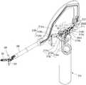
계속해서 도면을 참조하면, 본 발명의 제1 실시예에 따른 수술용 인스트루먼트(100)에서, 피치 조작부(111)와 엔드 툴(end tool)(120)이 동일하거나 또는 평행한 축(X축) 상에 형성될 수 있다. 즉, 연결부(140)의 절곡부(141)의 일 단부에는 피치 조작부(111)의 피치 회전축(1111)이 형성되고, 연결부(140)의 타 단부에는 엔드 툴(end tool)(120)이 형성되는 것이다.Continuing to refer to the drawings, in the
그리고, 연결부(140)의 중간중간, 특히 절곡부(141) 부분에는 와이어들의 경로를 변경 또는 가이드해주는 하나 이상의 중개 풀리(MP)들이 배치될 수 있다. 이와 같은 중개 풀리(MP)들에 와이어들의 적어도 일부가 감기도록 형성되어 와이어들의 경로를 가이드해줌으로써, 절곡부(141)의 절곡된 형상을 따라 와이어가 배치될 수 있는 것이다.In addition, one or more intermediate pulleys MP for changing or guiding the paths of the wires may be disposed in the middle of the
여기서, 도면에는 연결부(140)는 절곡부(141)를 구비하여 소정의 곡률을 갖도록 만곡되어 형성되는 것으로 도시되어 있으나, 본 발명의 사상은 이에 제한되지 아니하며, 연결부(140)가 필요에 따라 직선으로 형성되거나, 또는 1회 이상 절곡되어 형성될 수도 있으며, 이와 같은 경우에도 피치 조작부(111)와 엔드 툴(end tool)(120)은 실질적으로 동일 또는 평행한 축 상에 형성되는 것이라고 말할 수 있을 것이다. 또한, 도 3에는 피치 조작부(111)와 엔드 툴(end tool)(120)이 X축과 평행한 축 상에 각각 형성되는 것으로 도시되어 있으나, 본 발명의 사상은 이에 제한되지 아니하며, 피치 조작부(111)와 엔드 툴(end tool)(120)이 서로 상이한 축 상에 형성될 수도 있을 것이다.
Here, in the drawings, the
본 실시예에서의 액츄에이션 동작, 요 동작, 피치 동작을 설명하면 다음과 같다.The actuation motion, yaw motion, and pitch motion in this embodiment will be described as follows.
먼저 액츄에이션 동작은 다음과 같다.First, the actuation operation is as follows.
사용자가 제1 액츄에이션 회전부(1132a)에 검지 손가락을 끼우고, 제2 액츄에이션 회전부(1132b)에 엄지 손가락을 끼운 상태에서 어느 한 손가락 또는 양 손가락을 모두 이용하여 액츄에이션 회전부(1132a)(1132b)를 회전시키면, 제1 액츄에이션 회전부(1132a)와 고정결합된 제1 액츄에이션 풀리(113P1) 및 제1 액츄에이션 기어(1134a)는 제1 액츄에이션 회전축(1131a)을 중심으로 회전하고, 제2 액츄에이션 회전부(1132b)와 고정결합된 제2 액츄에이션 풀리(1133b) 및 제2 액츄에이션 기어(1134b)가 제2 액츄에이션 회전축(1131b)을 중심으로 회전한다. 이때 제1 액츄에이션 풀리(113P1)와 제2 액츄에이션 풀리(113P2)는 서로 반대 방향으로 회전하게 되며, 따라서 제1 액츄에이션 풀리(113P1)에 일 단부가 고정결합되어 감긴 제1 조 와이어(130J1)와 제2 액츄에이션 풀리(113P2)에 일 단부가 고정결합되어 감긴 제2 조 와이어(130J2) 역시 서로 반대 방향으로 이동하게 된다. 그리고, 이와 같은 회전력이 동력 전달부(130)를 통해 엔드 툴(120)로 전달되어, 엔드 툴(120)의 두 개의 조(jaw)(121)(122)가 액츄에이션 동작을 수행한다. 여기서 액츄에이션 동작이란 상술한 바와 같이, 두 개의 조(jaw)(121, 122)가 서로 반대 방향으로 회전하면서, 조(jaw)(121, 122)를 벌리거나 닫는 동작을 의미한다. 즉, 액츄에이션 조작부(113)의 액츄에이션 회전부(1132a)(1132b)를 서로 가까워지는 방향으로 회전시키면 제1 조(jaw)(121)는 반시계 방향으로 회전하고 제2 조(jaw)(122)는 시계 방향으로 회전하면서 엔드 툴(120)이 닫히고, 액츄에이션 조작부(113)의 액츄에이션 회전부(1132a)(1132b)를 서로 멀어지는 방향으로 회전시키면 제1 조(jaw)(121)는 시계 방향으로 회전하고 제2 조(jaw)(122)는 반시계 방향으로 회전하면서 엔드 툴(120)이 열리게 되는 것이다. 본 실시예에서는 상술한 액츄에이션 조작을 위해 제1 액츄에이션 회전부(1132a)와 제2 액츄에이션 회전부(1132b)를 구비하여 제2 손잡이를 구성하였으며, 두 개의 손가락을 파지하여 조작할 수 있도록 하였다. 그러나, 엔드 툴(120)의 두 개의 조를 서로 열고 닫는 액츄에이션 조작을 위한 액츄에이션 조작부(113)의 구성은, 상술한 바와 다르게 하나의 액츄에이션 회전부로 두 개의 액츄에이션 풀리(제1 액츄에이션 풀리(113P1), 제2 액츄에이션 풀리(113P2))가 서로 반대로 동작하도록 하는 구성 등의 다른 변형예도 충분히 가능할 것이다.In a state where the user inserts the index finger into the first
다음으로 요 동작은 다음과 같다.Next, the yaw operation is as follows.
사용자가 제1 손잡이(114)를 잡고 있는 상태에서 요 회전축(1121)을 중심으로 제1 손잡이(114)를 회전시키면, 액츄에이션 조작부(113) 및 요 조작부(112)가 요 회전축(1121)을 중심으로 요 회전을 하게 된다. 즉, 제1 조 와이어(130J1)가 고정결합되어 있는 제1 액츄에이션 조작부(113a)의 제1 액츄에이션 풀리(113P1)가 요 회전축(1121)을 중심으로 회전하게 되면, 제1 조 요 풀리(112P1)에 감겨있는 제1 조 와이어(130J1)가 이동하게 된다. 마찬가지로, 제2 조 와이어(130J2)가 고정결합되어 있는 제2 액츄에이션 조작부(113b)의 제2 액츄에이션 풀리(113P2)가 요 회전축(1121)을 중심으로 회전하게 되면, 제2 조 요 풀리(112P2)에 감겨있는 제2 조 와이어(130J2)가 이동하게 된다. 이때, 제1 조(121)에 연결된 제1 조 와이어(130J1)와 제2 조(122)에 연결된 제2 조 와이어(130J2)는, 요 회전시에 제1 조(121)와 제2 조(122)가 같은 방향으로 회전하도록 제1 조 요 풀리(112P1)와 제2 조 요 풀리(112P2)에 감겨 있다. 그리고, 이와 같은 회전력이 동력 전달부(130)를 통해 엔드 툴(120)로 전달되어, 엔드 툴(120)의 두 개의 조(jaw)(121)(122)가 같은 방향으로 회전하는 요 동작을 수행한다.When the user rotates the
이때 요 프레임(1123)이 제1 손잡이(114), 요 회전축(1121), 제1 액츄에이션 회전축(1131a), 제2 액츄에이션 회전축(1131b)을 연결하기 때문에, 제1 손잡이(114)와 요 조작부(112)와 액츄에이션 조작부(113)는 요 회전축(1121)을 중심으로 함께 회전하게 된다.At this time, since the
다음으로 피치 동작은 다음과 같다.Next, the pitch operation is as follows.
사용자가 제1 손잡이(114)를 잡고 있는 상태에서 피치 회전축(1111)을 중심으로 제1 손잡이(114)를 회전시키면, 액츄에이션 조작부(113), 요 조작부(112) 및 피치 조작부(111)가 피치 회전축(1111)을 중심으로 피치 회전을 하게 된다. 즉, 제1 조 와이어(130J1)가 고정결합되어 있는 제1 액츄에이션 조작부(113a)의 제1 액츄에이션 풀리(113P1)가 피치 회전축(1111)을 중심으로 회전하게 되면, 제1 조 피치 풀리-a(111P1a)와 제1 조 피치 풀리-b(111P1b)에 감겨 있는 제1 조 와이어(130J1)가 이동하게 된다. 마찬가지로, 제2 조 와이어(130J2)가 고정결합되어 있는 제2 액츄에이션 조작부(113b)의 제2 액츄에이션 풀리(113P2)가 피치 회전축(1111)을 중심으로 회전하게 되면, 제2 조 피치 풀리-a(111P2a)와 제2 조 피치 풀리-b(111P2b)에 감겨있는 제2 조 와이어(130J2)가 이동하게 된다. 이때, 도 5를 통해 설명한 것 처럼, 제1 조 와이어(130J1)의 양 가닥이 서로 같은 방향으로 이동하고, 제2 조 와이어(130J2)의 양 가닥이 서로 같은 방향으로 이동하여, 제1 조(121)와 제2 조(122)가 피치 회전을 할 수 있도록, 제1 조 와이어(130J1)와 제2 조 와이어(130J2)는 제1 조 피치 풀리(111P1a, 111P1b)와 제2 조 피치 풀리(111P2a, 111P2b)에 감기게 된다. 그리고, 이와 같은 회전력이 동력 전달부(130)를 통해 엔드 툴(120)로 전달되어, 엔드 툴(120)의 두 개의 조(jaw)(121)(122)가 피치 동작을 수행한다.When the user rotates the
이때 피치 프레임(1113)은 요 프레임(1123)과 연결되고, 요 프레임(1123)은 제1 손잡이(114), 요 회전축(1121), 제1 액츄에이션 회전축(1131a), 제2 액츄에이션 회전축(1131b)을 연결하기 때문에, 피치 프레임(1113)이 피치 회전축(1111)을 중심으로 회전하면 피치 프레임(1113)과 연결된 요 프레임(1123), 제1 손잡이(114), 요 회전축(1121), 제1 액츄에이션 회전축(1131a), 제2 액츄에이션 회전축(1131b)이 함께 회전하게 된다. 즉, 피치 조작부(111)가 피치 회전축(11111)을 중심으로 회전하면 액츄에이션 조작부(113) 및 요 조작부(112)가 피치 조작부(111)와 함께 회전하는 것이다.At this time, the
정리하면, 본 발명의 일 실시예에 따른 수술용 인스트루먼트(100)는 각 관절 지점(액츄에이션 관절, 요 관절, 피치 관절)에 풀리가 형성되며, 이 풀리에는 와이어(제1 조 와이어 또는 제2 조 와이어)가 감겨있고, 조작부의 회전 조작(액츄에이션 회전, 요 회전, 피치 회전)이 각 와이어의 이동을 일으켜, 결과적으로 엔드 툴(120)의 원하는 동작을 유도하는 것을 특징으로 한다. 나아가, 각 풀리들의 일 측에는 보조 풀리들이 형성될 수 있으며, 이들 보조 풀리에 의하여 하나의 풀리에 와이어가 여러 번 감기지 않을 수 있게 된다.
In summary, in the
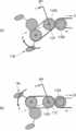
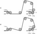
도 8은 도 7에 도시된 본 발명의 일 실시예에 따른 수술용 인스트루먼트(100)의 관절을 구성하는 풀리 및 와이어의 구성만을 간략하게 도시한 도면이다. 도 8에서는 관절 동작과 관계없이 와이어의 경로를 변경하기 위한 중개 풀리들은 생략되었다.8 is a view schematically showing only the configuration of a pulley and a wire constituting the joint of the
도 8을 참조하면, 조작부(110)는 제1 조(jaw)(121)의 회전 운동과 관련된 제1 액츄에이션 풀리(113P1), 제1 조 요 풀리(112P1), 제1 조 요 보조 풀리(112S1), 제1 조 피치 풀리-a(111P1a), 제1 조 피치 풀리-b(111P1b), 제1 조 피치 보조 풀리-a(111S1a), 제1 조 피치 보조 풀리-b(111S1b)를 포함할 수 있다.Referring to FIG. 8, the
또한, 조작부(110)는 제2 조(jaw)(122)의 회전 운동과 관련된 제2 액츄에이션 풀리(113P2), 제2 조 요 풀리(112P2), 제2 조 요 보조 풀리(112S2), 제2 조 피치 풀리-a(111P2a), 제2 조 피치 풀리-b(111P2b), 제2 조 피치 보조 풀리-a(111S2a), 제2 조 피치 보조 풀리-b(111S2b)를 포함할 수 있다. (조작부(100)에서의 각 풀리들의 배치 및 구성은 엔드 툴(120)에서의 각 풀리들의 배치 및 구성과 원리적으로 동일하므로, 도면상에서의 도면 부호의 구체적인 표기는 일부 생략하도록 한다.)In addition, the
제1 조 요 풀리(112P1)와 제2 조 요 풀리(112P2)는 동일한 축인 요 회전축(1121)을 중심으로 서로 독립적으로 회전 가능하도록 형성될 수 있다. 이때, 제1 조 요 풀리(112P1)와 각각 제2 조 요 풀리(112P2)는 서로 마주 보도록 형성되어 독립적으로 회전 가능하도록 형성되는 두개의 풀리로 형성될 수 있다.
제1 조 요 보조 풀리(112S1)와 제2 조 요 보조 풀리(112S2)는 동일한 축을 중심으로 서로 독립적으로 회전 가능하도록 형성될 수 있다. 이때, 제1 조 요 보조 풀리(112S1)는 서로 마주보도록 형성되어 독립적으로 회전 가능하도록 형성되는 두 개의 풀리로 형성될 수 있으며, 이때 두 개의 풀리는 서로 다른 직경을 갖도록 형성될 수 있다. 마찬가지로, 제2 조 요 보조 풀리(112S2)는 서로 마주보도록 형성되어 독립적으로 회전 가능하도록 형성되는 두 개의 풀리로 형성될 수 있으며, 이때 두 개의 풀리는 서로 다른 직경을 갖도록 형성될 수 있다.
제1 조 피치 보조 풀리-a(111S1a), 제1 조 피치 보조 풀리-b(111S1b), 제2 조 피치 보조 풀리-a(111S2a), 제2 조 피치 보조 풀리-b(111S2b)는 동일한 축을 중심으로 서로 독립적으로 회전 가능하도록 형성될 수 있다. 이때 제1 조 피치 보조 풀리-a(111S1a)와 제1 조 피치 보조 풀리-b(111S1b)는 서로 다른 직경을 갖도록 형성될 수 있다. 또한, 제2 조 피치 보조 풀리-a(111S2a)와 제2 조 피치 보조 풀리-b(111S2b)는 서로 다른 직경을 갖도록 형성될 수 있다.
제1 조 피치 풀리-a(111P1a), 제1 조 피치 풀리-b(111P1b), 제2 조 피치 풀리-a(111P2a), 제2 조 피치 풀리-b(111P2b)는 동일한 축인 피치 회전축(1111)을 중심으로 서로 독립적으로 회전 가능하도록 형성될 수 있다.
제1 조 와이어(130J1)는 조작부(110)의 제1 조 피치 풀리-a(111P1a), 제1 조 피치 보조 풀리-a(111S1a), 제1 조 요 보조 풀리(112S1), 제1 조 요 풀리(112P1)를 차례로 지나서 제1 액츄에이션 풀리(113P1)에 감긴 후, 다시 제1 조 요 풀리(112P1), 제1 조 요 보조 풀리(112S1), 제1 조 피치 보조 풀리-b(111S1b), 제1 조 피치 풀리-b(111P1b)를 차례로 지나도록 형성되어, 제1 조 구동 와이어(130J1)가 상기 풀리들을 회전시키면서 상기 풀리들을 따라서 이동할 수 있도록 형성된다. 이때, 제1 액츄에이션 풀리(113P1)의 일 지점에 제1 조 와이어(130J1)가 고정결합될 수 있다.
제2 조 와이어(130J2)는 조작부(110)의 제2 조 피치 풀리-a(111P2a), 제2 조 피치 보조 풀리-a(111S2a), 제2 조 요 보조 풀리(112S2), 제2 조 요 풀리(112P2)를 차례로 지나서 제2 액츄에이션 풀리(113P2)에 감긴 후, 다시 제2 조 요 풀리(112P2), 제2 조 요 보조 풀리(112S2), 제2 조 피치 보조 풀리-b(111S2b), 제2 조 피치 풀리-b(111P2b)를 차례로 지나도록 형성되어, 제2 조 와이어(130J2)가 상기 풀리들을 회전시키면서 상기 풀리들을 따라서 이동할 수 있도록 형성된다. 이때, 제2 액츄에이션 풀리(113P2)의 일 지점에 제2 조 와이어(130J2)가 고정결합될 수 있다.
Article 2 wire (130J2), Article 2 pitch pulley-a (111P2a) of the
도 9는 도 7에 도시된 본 발명의 일 실시예에 따른 수술용 인스트루먼트(100)의 액츄에이션 동작 및 요 동작과 관련된 풀리 및 와이어의 구성을 제1 조와 제2 조 각각에 대해 풀어서 도시한 그림이다. 도 9(a)는 제2 조와 관련된 풀리 및 와이어만을 나타낸 도면이고, 도 9(b)는 제1 조와 관련된 풀리 및 와이어만을 나타낸 도면이다. 그리고, 도 10은 도 7의 수술용 인스트루먼트의 요 동작을 나타내는 사시도이다.FIG. 9 is a diagram showing the configuration of pulleys and wires related to the actuation and yaw movements of the
먼저 액츄에이션 동작의 와이어 동작에 대해 설명한다.First, the wire operation of the actuation operation will be described.
도 9(b)를 참조하면, 제1 액츄에이션 회전부(1132a)가 제1 액츄에이션 회전축(1131a)을 중심으로 화살표 OPA1 방향으로 회전하면, 제1 액츄에이션 회전부(1132a)와 연결된 제1 액츄에이션 풀리(113P1)가 회전하고, 제1 액츄에이션 풀리(113P1)에 감겨있는 제1 조 와이어(130J1)의 양 가닥은 각각 W1a, W1b 방향으로 이동하게 되어, 결과적으로 조작부의 제1 조(121)가 화살표 EPA1 방향으로 회전하게 된다.9(b), when the first
도 9(a)를 참조하면, 제2 액츄에이션 회전부(1132b)가 제2 액츄에이션 회전축(1131b)을 중심으로 화살표 OPA2 방향으로 회전하면, 제2 액츄에이션 회전부(1132b)와 연결된 제2 액츄에이션 풀리(113P2)가 회전하고, 제2 액츄에이션 풀리(113P2)에 감겨있는 제2 조 와이어(130J2)의 양 가닥은 각각 W2a, W2b 방향으로 이동하게 되어, 결과적으로 조작부의 제2 조(122)가 화살표 EPA2 방향으로 회전하게 된다. 따라서 사용자가 제1 액츄에이션 회전부(1132a)와 제2 액츄에이션 회전부(1132b)를 서로 가까워지는 방향으로 조작하면, 엔드 툴의 제1 조(121) 및 제2 조(122)가 서로 가까워지는 동작이 수행된다.Referring to FIG. 9(a), when the second
다음으로 요 동작의 와이어 동작에 대해 설명한다.Next, the wire operation of the yaw operation will be described.
먼저 요 회전축(1121)과 제1 액츄에이션 회전축(1131a) 및 제2 액츄에이션 회전축(1131b)은 요 프레임(도 7의 1123 참조)에 의해 연결되어 있으므로, 요 회전축(1121)과 제1 액츄에이션 회전축(1131a)과 제2 액츄에이션 회전축(1131b)은 일체로 함께 회전하게 된다.First, the
도 9(b)를 참조하면, 제1 손잡이(114)를 요 회전축(1121)을 중심으로 화살표 OPY1 방향으로 회전하면, 제1 액츄에이션 풀리(113P1)와 제1 조 요 풀리(112P1)와 여기에 감겨있는 제1 조 와이어(130J1)가 전체적으로 요 회전축(1121)을 중심으로 회전하여, 결과적으로 제1 조 요 풀리(112P1)에 감겨있는 제1 조 와이어(130J1)의 양 가닥은 각각 W1a, W1b 방향으로 이동하게 되어, 결과적으로 엔드 툴(120)의 제1 조(121)가 화살표 EPY1 방향으로 회전하게 된다.9(b), when the
도 9(a)를 참조하면, 제1 손잡이(114)를 요 회전축(1121)을 중심으로 화살표 OPY2 방향으로 회전하면, 제2 액츄에이션 풀리(113P2)와 제2 조 요 풀리(112P2)와 여기에 감겨있는 제2 조 와이어(130J2)가 전체적으로 요 회전축(1121)을 중심으로 회전하여, 결과적으로 제2 조 요 풀리(112P2)에 감겨있는 제2 조 와이어(130J2)의 양 가닥은 각각 W1a의 반대쪽 및 W1b의 반대쪽으로 이동하게 되어, 결과적으로 엔드 툴(120)의 제1 조(121)가 화살표 EPY2 방향으로 회전하게 된다.
9(a), when the
도 11은 도 7에 도시된 본 발명의 일 실시예에 따른 수술용 인스트루먼트(100)의 피치 동작과 관련된 풀리 및 와이어의 구성을 제1 조와 제2 조 각각에 대해 풀어서 도시한 그림이다. 도 11(a)는 제2 조와 관련된 풀리 및 와이어만을 나타낸 도면이고, 도 11(b)는 제1 조와 관련된 풀리 및 와이어만을 나타낸 도면이다. 도 8에 도시된 바와 같이, 피치 동작과 관련된 풀리는 각각 2개이며, 각 와이어의 양 가닥이 같은 경로로 감겨져 있어서, 도 11에서는 이를 하나의 선으로 표현하였다. 그리고, 도 12는 도 7의 수술용 인스트루먼트의 피치 동작을 나타내는 사시도이다.FIG. 11 is a diagram illustrating the configuration of pulleys and wires related to the pitch operation of the
도 11(b)를 참조하면, 제1 손잡이(114)를 피치 회전축(1111)을 중심으로 화살표 OPP1 방향으로 회전하면, 제1 액츄에이션 풀리(113P1), 제1 조 피치 보조 풀리(111S1a, 111S1b), 제1 조 피치 풀리(111P1a, 111P1b) 등과 여기에 감겨있는 제1 조 와이어(130J1)가 전체적으로 피치 회전축(1111)을 중심으로 회전한다. 이 때, 도 8과 같이 제1 조 와이어(130J1)의 양 가닥은 제1 조 피치 풀리(111P1a, 111P1b)의 위쪽에 감겨 있기 때문에 화살표 W1 쪽으로 이동하게 된다. 결과적으로 도 5를 통해 설명한 것 처럼, 엔드 툴(120)의 제1 조(121)가 화살표 EPP1 방향으로 회전하게 된다.Referring to FIG. 11(b), when the
도 11(a)를 참조하면, 제1 손잡이(114)를 피치 회전축(1111)을 중심으로 화살표 OPP2 방향으로 회전하면, 제2 액츄에이션 풀리(113P2), 제2 조 피치 보조 풀리(111S2a, 111S2b), 제2 조 피치 풀리(111P2a, 111P2b) 등과 여기에 감겨있는 제2 조 와이어(130J2)가 전체적으로 피치 회전축(1111)을 중심으로 회전한다. 이때, 도 8과 같이 제2 조 와이어(130J2)의 양 가닥은 제2 조 피치 풀리(111P2a, 111P2b)의 아래쪽에 감겨 있기 때문에 화살표 W2 쪽으로 이동하게 된다. 결과적으로 도 5를 통해 설명한 것 처럼, 엔드 툴(120)의 제2 조(122)가 화살표 EPP2 방향으로 회전하게 된다.Referring to FIG. 11(a), when the
따라서, 제1 실시예를 나타내는 도 7은 도 8, 9, 10, 11, 12를 통해 동작원리를 설명할 수 있으며, 액츄에이션 조작, 요 조작, 피치 조작은 서로에 독립적으로 조작이 가능하다.Accordingly, Fig. 7 showing the first embodiment can explain the operation principle through Figs. 8, 9, 10, 11, and 12, and actuation operation, yaw operation, and pitch operation can be operated independently of each other.
도 1을 통해 설명한 것처럼, 액츄에이션 조작부(113), 요 조작부(112), 피치 조작부(111)는 자신의 회전축이 각 조작부의 뒤쪽에 위치함으로써, 엔드 툴의 관절 구성과 동일하게 구성되어, 사용자가 직관적으로 일치하는 조작을 수행하는 것이 가능하다.As described with reference to FIG. 1, the
특히, 본 발명의 일 실시예에 따른 수술용 인스트루먼트(100)는 각 관절 지점(액츄에이션 관절, 요 관절, 피치 관절)에 풀리가 형성되며, 이 풀리를 와이어(제1 조 와이어 또는 제2 조 와이어)가 감도록 형성되어 있고, 조작부의 회전 조작(액츄에이션 회전, 요 회전, 피치 회전)이 각 와이어의 이동을 일으켜, 결과적으로 엔드 툴(120)의 원하는 동작을 유도하는 것을 특징으로 한다. 나아가, 각 풀리들의 일 측에는 보조 풀리들이 형성될 수 있으며, 이들 보조 풀리에 의하여 하나의 풀리에 와이어가 여러 번 감기지 않을 수 있게 되어, 풀리에 감기는 와이어가 서로 접촉하지 않으며, 풀리에 감겨들어 가는 와이어와 감겨나오는 와이어의 경로도 안전하게 형성되어, 와이어의 동력전달의 안전성 및 효율 등을 향상시킬 수 있다.In particular, in the
한편, 상술한 바와 같이 요 조작부(112)와 액츄에이션 조작부(113)는 제1 손잡이(114) 상에 직접 형성되어 있다. 따라서, 제1 손잡이(114)가 피치 회전축(1111)을 중심으로 회전하게 되면, 요 조작부(112)와 액츄에이션 조작부(113) 역시 제1 손잡이(114)와 함께 회전하게 된다. 이로 인해, 요 조작부(112)와 액츄에이션 조작부(113)의 좌표계는 고정된 것이 아니라, 제1 손잡이(114)의 회전에 따라 상대적으로 계속 변화하게 된다. 즉, 도 2 등에는 요 조작부(112) 및 액츄에이션 조작부(113)는 Z축과 평행한 것으로 도시되어 있다. 그러나, 제1 손잡이(114)가 회전하게 되면, 요 조작부(112)과 액츄에이션 조작부(113)가 Z축과 평행하지 않게 된다. 즉, 요 조작부(112)과 액츄에이션 조작부(113)의 좌표계가 제1 손잡이(114)의 회전에 따라 변화된 것이다. 다만, 본 명세서에서는 설명의 편의를 위하여, 별도의 설명이 없는 이상, 요 조작부(112)과 액츄에이션 조작부(113)의 좌표계는 도 2와 같이 제1 손잡이(114)가 연결부(140)에 대해서 수직으로 위치한 상태를 기준으로 하여 설명하였다.
Meanwhile, as described above, the
<관절의 다양한<various of joints변형예Variation>>
요 회전 또는 풀리 회전을 위해 주 관절 풀리와 추가적인 보조 풀리로 구성된 관절 구조는 둘의 구성에 따라 다른 변형 예가 가능하여 직접형 관절과 간접형 관절로 나뉠 수 있다.The joint structure consisting of a main joint pulley and an additional auxiliary pulley for yaw rotation or pulley rotation can be divided into a direct joint and an indirect joint because different modifications are possible according to the configuration of the two.
(직접형 관절과 간접형 관절 -요 관절)(Direct joint and indirect joint-yaw joint)
도 13은 요 관절의 직접형 관절의 일 예를 나타내는 도면이고, 도 14는 요 관절의 간접형 관절의 일 예를 나타내는 도면이다. 도 13(a) 및 도 14(a)는 제2 조와 관련된 풀리 및 와이어만을 나타낸 도면이고, 도 13(b) 및 도 14(b)는 제1 조와 관련된 풀리 및 와이어만을 나타낸 도면이다.13 is a diagram illustrating an example of a direct joint of a yaw joint, and FIG. 14 is a diagram illustrating an example of an indirect joint of a yaw joint. 13(a) and 14(a) are views showing only pulleys and wires related to the second set, and FIGS. 13(b) and 14(b) are views showing only the pulleys and wires related to the first set.
여기서, 직접형 관절이란 하나의 관절 운동을 위해 서로 인접한 두 개의 풀리를 구비하는 구성에서 관절 위치에 해당하는 풀리와 보조 풀리와의 관계에 있어서, 해당 관절부의 회전축에 대해 해당 관절부가 회전할 때, 보조 풀리는 해당 관절부의 회전축을 기준으로 회전하지 않고, 관절 위치에 해당하는 풀리만 해당 관절부의 회전축을 기준으로 회전하는 경우를 의미한다. 한편, 간접형 관절이란 해당 관절부의 회전축에 대해 해당 관절부가 회전할 때, 관절 위치에 해당하는 풀리 뿐만 아니라, 보조 풀리도 해당 관절부의 회전축을 기준으로 회전하는 경우를 의미한다.Here, the direct joint is a configuration including two pulleys adjacent to each other for one joint motion, in the relationship between the pulley corresponding to the joint position and the auxiliary pulley, when the joint portion rotates with respect to the rotation axis of the joint portion, The auxiliary pulley does not rotate based on the rotation axis of the joint part, but refers to a case where only the pulley corresponding to the joint position rotates based on the rotation axis of the joint part. On the other hand, the indirect joint refers to a case where, when the joint part rotates with respect to the rotation axis of the joint part, not only the pulley corresponding to the joint position but also the auxiliary pulley rotates based on the rotation axis of the joint part.
한편, 직접형 관절을 도시한 도 13은 제1 조(121)의 요 운동을 위하여 서로 이웃하게 형성된 제1 조 요 풀리(112P1)와 제1 조 요 보조 풀리(112S1)를 구비하며, 요 회전축(1121) 상에 위치하여 요 회전 시 요 회전축(1121)을 중심으로 회전하는, 도면 상 왼쪽에 위치하는, 풀리가 제1 조 요 풀리(112P1)가 된다. 이때, 제1 조 요 보조 풀리(112S1)는 도면상 오른쪽에 위치하여, 요 회전 시 요 회전축(1121)을 중심으로 회전하지 않는다.On the other hand, FIG. 13 showing a direct joint is provided with
한편, 간접형 관절을 도시한 도 14는 제1 조(121)의 요 운동을 위하여 서로 이웃하게 형성된 제1 조 요 풀리(112P1)와 제1 조 요 보조 풀리(112S1)를 구비하며, 요 회전축(1121) 상에 위치하여 요 회전 시 요 회전축(1121)을 중심으로 회전하는, 도면 상 오른쪽에 위치하는, 풀리가 제1 조 요 풀리(112P1)가 된다. 이때, 제1 조 요 보조 풀리(112S1)는 도면상 왼쪽에 위치하여, 요 회전 시 요 회전축(1121)을 중심으로 회전한다.On the other hand, Figure 14 showing an indirect joint is provided with
이와 같은 직접형 관절과 간접형 관절은, 관절을 동일한 방향으로 회전하였을 때 와이어의 이동방향에 있어서 차이점이 있다. 즉, 직접형 관절을 도시한 도 13에서 요 회전축(1121)을 OPY 방향으로 회전시키면 제1 조 와이어(130J1) 및 제2 조 와이어(130J2)의 일 측은 화살표 D1 방향으로 이동하는 반면, 간접형 관절을 도시한 도 14에서 요 회전축(1121)을 OPY 방향으로 회전시키면 제1 조 와이어(130J1) 및 제2 조 와이어(130J2)의 일 측은 D1과 반대 방향인 화살표 D2 방향으로 이동하게 된다.There is a difference between such a direct joint and an indirect joint in the direction of movement of the wire when the joint is rotated in the same direction. That is, in FIG. 13 showing a direct joint, when the
이와 같이 직접형 관절과 간접형 관절 중 어느 방식으로 관절 구조를 구성하느냐에 따라 동일한 방향의 요 회전에 대해, 와이어의 이동 방향을 서로 반대로 구성할 수 있는 효과를 얻을 수 있다.
As described above, depending on which method of the direct joint and the indirect joint to configure the joint structure, it is possible to obtain the effect of configuring the moving directions of the wires in opposite directions for the same direction of yaw rotation.
(직접형 관절과 간접형 관절 - 피치 관절)(Direct joint and indirect joint-pitch joint)
도 15는 피치 관절의 간접형 관절의 일 예를 나타내는 도면이고, 도 16은 피치 관절의 직접형 관절의 일 예를 나타내는 도면이다. 도 15(a) 및 도 16(a)는 제2 조와 관련된 풀리 및 와이어만을 나타낸 도면이고, 도 15(b) 및 도 16(b)는 제1 조와 관련된 풀리 및 와이어만을 나타낸 도면이다.15 is a diagram illustrating an example of an indirect joint of a pitch joint, and FIG. 16 is a diagram illustrating an example of a direct joint of a pitch joint. 15(a) and 16(a) are views showing only pulleys and wires related to the second set, and FIGS. 15(b) and 16(b) are views showing only the pulleys and wires related to the first set.
간접형 관절을 도시한 도 15(b)는 제1 조(121)의 피치 운동을 위하여 서로 이웃하게 형성된 제1 조 피치 풀리-a(111P1a)와 제1 조 피치 보조 풀리-a(111S1a)를 구비하며, 이때 도면상 오른쪽에 위치한 풀리가 제1 조 피치 풀리-a(111P1a)가 된다.Fig. 15(b) showing an indirect joint shows the first group pitch pulley-a (111P1a) and the first group pitch auxiliary pulley-a (111S1a) formed adjacent to each other for the pitch movement of the
직접형 관절을 도시한 도 16(b)는 제1 조(121)의 피치 운동을 위하여 서로 이웃하게 형성된 제1 조 피치 풀리-a(111P1a)와 제1 조 피치 보조 풀리-a(111S1a)를 구비하며, 이때 도면상 왼쪽에 위치한 풀리가 제1 조 피치 풀리-a(111P1a)가 된다.Fig. 16(b) showing a direct joint shows the first group pitch pulley-a(111P1a) and the first group pitch auxiliary pulley-a(111S1a) formed adjacent to each other for the pitch movement of the
이와 같이 직접형 관절과 간접형 관절 중 어느 방식으로 관절 구조를 구성하느냐에 따라 동일한 방향의 피치 회전에 대해, 와이어의 이동 방향을 서로 반대로 구성할 수 있는 효과를 얻을 수 있으며, 이를 통해 피치 풀리에 와이어가 감기는 방향을 달리할 수도 있다.
In this way, depending on whether the joint structure is composed of a direct joint or an indirect joint, it is possible to obtain the effect of configuring the moving directions of the wires in opposite directions for the same direction of pitch rotation, and through this, the wire to the pitch pulley. It is also possible to change the direction of winding.
(풀리 및(Pulley and와이어wire 구성의 다양한 Variety of configuration변형예Variation))
도 9에 도시된 본 발명의 제1 실시예에 따른 수술용 인스트루먼트(100)의 액츄에이션 동작 및 요 동작과 관련된 풀리 및 와이어 구성은 와이어의 경로, 관절 풀리의 크기 및 배치, 조작부 및 엔드툴 구성 등의 변형을 통한 다양한 변형예를 가질 수 있다. 이하에서는 상정할 수 있는 풀리 및 와이어 구성의 다양한 변형예에 관하여 설명하도록 한다.
The pulley and wire configuration related to the actuation operation and yaw movement of the
도 17은 도 9에 도시된 본 발명의 일 실시예에 따른 수술용 인스트루먼트(100)의 제1 조(121)의 동작과 관련된 풀리 및 와이어의 구성과 그 변형예들을 도시한 그림이다.FIG. 17 is a diagram showing a configuration of a pulley and a wire related to the operation of the
도 17(a)을 참조하면, 도 17(a)에 도시된 본 발명의 일 실시예에 따른 수술용 인스트루먼트(100)는 기본적으로 연결부(140) 내에서 와이어가 교차되지 아니한다. 즉, 엔드 툴(120)과 조작부(110)를 연결하는 연결부(140) 내에서, 제1 조 와이어(130J1)의 양 가닥은 서로 교차하지 않은 상태로 형성되며, 제2 조 와이어(130J2) 또한 그 양 가닥은 서로 교차하지 않은 상태로 형성된다.Referring to FIG. 17(a), the
한편, 도 17(a)에 도시된 본 발명의 일 실시예에 따른 수술용 인스트루먼트(100)는 연결부(140) 내에서 각 와이어가 퍼져나가도록 형성된다. 즉, 중개 풀리들의 크기 및 간격에 의해, 엔드 툴(120)에서의 제1 조 와이어(130J1)의 양 가닥간의 간격은 중개 풀리(MP)로 연결되며 형성되는 양 가닥간의 간격보다 작게 형성되기 때문에, 엔드 툴(120)에서 중개 풀리 쪽으로 갈수록 제1 조 와이어(130J1)의 양 가닥간의 간격이 점점 멀어져서, 전체적으로 제1 조 와이어(130J1)가 퍼져나가도록 형성되는 것이다.On the other hand, the
한편, 도 17(a)에 도시된 본 발명의 일 실시예에 따른 수술용 인스트루먼트(100)는 조작부(110)의 요 관절이 직접형으로 형성된다. 즉, 수술용 인스트루먼트(100)는 제1 조(121)의 요 운동을 위하여 서로 이웃하게 형성된 제1 조 요 풀리(112P1)와 제1 조 요 보조 풀리(112S1)를 구비하며, 이때 도면상 왼쪽에 위치한 풀리가 제1 조 요 풀리(112P1)가 되며, 제1 조 요 풀리(112P1)의 회전축이 요 회전축이 된다. 이때, 제1 조 요 보조 풀리(112S1)는 서로 마주보도록 형성되어 독립적으로 회전 가능하도록 형성되는 두 개의 풀리로 형성될 수 있으며, 이때 두 개의 풀리는 서로 다른 직경을 갖도록 형성될 수 있다. 이때, 제1 조 요 풀리(112P1)와 제1 조 요 보조 풀리(112S1)를 교차하여 감기는 와이어가 경로상 서로 겹치지 않도록, 제1 조 요 풀리(112P1)와 제1 조 요 보조 풀리(112S1) 각각은 두 개의 풀리를 구비하여, 제1 조 와이어(130J1)의 양 가닥이 높이차를 가지도록 할 수 있다. 그리고, 이를 위해 피치 보조 풀리도 서로 다른 직경을 갖는 두 개의 풀리(제1 조 피치 보조 풀리-a(111S1a) 및 제1 조 피치 보조 풀리-b(111S1b))를 가지도록 하여, 높이차가 나는 풀리들에 자연스럽게 제1 조 와이어(130J1)가 감기도록 구성한다.Meanwhile, in the
도 17(b)의 경우, 제1 조 요 보조 풀리(112S1)와 연결되는 피치 보조 풀리(제1 조 피치 보조 풀리-a(111S1a) 및 제1 조 피치 보조 풀리-b(111S1b))의 크기 및 배치를 도 17(a)의 경우와 달리함으로써, 도 17(b)의 아래 그림과 같이 제1 조 피치 보조 풀리-a(111S1a)에 감기는 와이어와 제1 조 피치 보조 풀리-b(111S1b)에 감기는 와이어의 높이가 반대가 되도록 배치할 수 있으며, 결과적으로 도 17(a)에 비해 제1 조 와이어(130J1)의 양 가닥의 상하 관계가 반대가 되도록 구성할 수 있다.In the case of Fig. 17(b), the size of the pitch auxiliary pulley (
도 17(c)의 경우, 제1 조의 구동을 위한 제1 액츄에이션 조작부(113a)를 도 17(a)의 경우와 다르게 한 구성이며, 조작부(110)에서의 액츄에이션 동작과 요 동작에 의한 엔드 툴(120)의 동작이 도 17(a)과 동일하게 수행되도록 하기 위해 제1 조 요 풀리(112P1)와 제1 액츄에이션 풀리(113P1)를 연결하는 제1 조 와이어(130J1)가 서로 교차되도록 구성할 수 있다.In the case of Fig. 17(c), the first
도 17(d)의 경우, 제1 조(121) 및 J11 풀리(123J11)의 구성을 달리한 경우로써, 도 17(a)와 다른 방향에 제1 조(121)가 형성되도록 한 경우이며, 이 때 요 동작을 위한 제1 조(121)의 회전 방향은 도 17(a)와 동일하나, 액츄에이션 동작을 위한 제1 조(121) 및 J11 풀리(123J11)의 회전 방향은 도 17(a)와 반대로 된다. 이를 위해 제1 액츄에이션 조작부(113a)의 동작이 도 17(a)와 반대로 제1 조 와이어(130J1)가 이동하도록 하기 위해 제1 조 요 풀리(112P1)와 제1 액츄에이션 풀리(113P1)를 연결하는 제1 조 와이어(130J1)가 서로 교차되도록 구성할 수 있다.In the case of FIG. 17(d), the configuration of the
본 구성에서는 2개의 요 풀리, 2개의 요 보조 풀리, 2개의 피치 풀리, 2개의 피치 보조 풀리가 형성될 수 있으며, 도면 상으로 교차되어 보이는 와이어는 실제로는 다른 경로상에 위치하여, 물리적으로 접촉하지 않으며, 이를 통해 와이어와 동력 전달의 안전성 및 효율 등을 향상시킬 수 있다.In this configuration, two yaw pulleys, two yaw auxiliary pulleys, two pitch pulleys, and two pitch auxiliary pulleys can be formed, and the wires that are seen intersecting in the drawing are actually located on different paths and are physically contacted. It does not, and through this, the safety and efficiency of wire and power transmission can be improved.
상기 설명은 제1 조의 액츄에이션, 요 동작에 대한 것이며, 도면 역시 제1 조의 액츄에이션, 요 동작의 설명을 위한 것이며, 중개 풀리 및 피치 동작에 관련된 풀리에 대한 설명이 없어도 충분히 이해가 가능한 바, 본 도면에서는 중개 풀리 및 피치 동작에 관련된 풀리는 생략되어 있다. 뿐만 아니라, 제2 조의 경우도 제1 조에 대한 도면과 설명을 통해 충분히 이해될 수 있는바, 제2 조에 대한 도면 및 설명은 생략하도록 한다.
The above description is for the actuation and yaw motion of
도 18은 도 17에 개시된 실시예의 다른 일 변형예를 나타내는 도면으로, 도 17에서 와이어 경로 등을 변형한 변형예이다.FIG. 18 is a view showing another modified example of the embodiment disclosed in FIG. 17, and is a modified example of a wire path and the like in FIG. 17.
도 18(a)의 경우 제1 실시예에 따른 구성과 달리, 제1 조(121)를 감도록 구성된 제1 조 와이어(130J1)의 양 가닥이 서로 인접한 두 개의 연결부 중개 풀리(MP)를 통과하도록 구성된 변형예이며, 제1 실시예에 따른 구성과 동일한 동작이 가능하도록, 제1 조 요 보조 풀리(112S1) 등의 구성이 변형된 예이다.In the case of FIG. 18(a), unlike the configuration according to the first embodiment, both strands of the first wire 130J1 configured to wind the
이를 위해, 제1 조 와이어(130J1)가 통과하는 서로 다른 크기의 피치 보조 풀리(제1 조 피치 보조 풀리-a(111S1a) 및 제1 조 피치 보조 풀리-b(111S1b))가 서로 인접하게 나란히 형성되었으며, 제1 조 피치 보조 풀리-a(111S1a)를 통과한 제1 조 와이어(130J1)는 제1 조 요 보조 풀리(112S1)에 감기도록 구성하고, 제1 조 피치 보조 풀리-b(111S1b)를 통과하는 제1 조 와이어(130J1)는 요 보조 풀리에 감기지 않고 바로 제1 조 요 풀리(112P1)에 감기도록 형성되며, 이를 통해 도 18(a)에서 설명하는 변형예는 제1 실시예와 동일한 동작이 가능해진다.도 18(a)에 따른 구성은, 와이어의 경로, 관절 풀리의 크기 및 배치, 조작부 및 엔드툴 구성 등의 변형을 통한 다양한 변형예를 가질 수 있다.To this end, pitch auxiliary pulleys of different sizes through which the first wire (130J1) passes (the first pitch auxiliary pulley-a (111S1a) and the first pitch auxiliary pulley-b (111S1b)) are arranged adjacent to each other. It was formed, and
도 18(b)의 경우, 요 보조 풀리와 연결되는 피치 보조 풀리의 크기를 도 18(a)의 경우와 달리함으로써, 도 18(b)의 아래 그림과 같이 제1 조 피치 보조 풀리-a(111S1a)에 감기는 와이어와 제1 조 피치 보조 풀리-b(111S1b)에 감기는 와이어의 높이가 반대가 되도록 배치할 수 있으며, 결과적으로 도 18(a)에 비해 제1 조 와이어(130J1)의 양 가닥의 관계가 반대가 되도록 구성할 수 있다. 도 18(c)의 경우, 제1 조의 구동을 위한 액츄에이션 조작부(113a)를 도 18(a)의 경우와 다르게 한 구성이며, 조작부(110)에서의 액츄에이션 동작과 요 동작에 의한 엔드 툴(120)의 동작이 도 18(a)와 동일하게 수행되도록 하기 위해 제1 조 요 풀리(112P1)와 제1 액츄에이션 풀리(113P1)를 연결하는 제1 조 와이어(130J1)가 서로 교차되도록 구성할 수 있다.In the case of Fig. 18(b), the size of the pitch auxiliary pulley connected to the yaw auxiliary pulley is different from that of Fig. 18(a), and as shown in the figure below of Fig. 18(b), the first pitch auxiliary pulley-a ( 111S1a) and the first pitch auxiliary pulley-b (111S1b) may be arranged so that the height of the wire wound is opposite, as a result of the
도 18(d)의 경우, 제1 조(121) 및 J11 풀리(123J11)의 구성을 달리한 경우로써, 도 18(a)과 다른 방향에 제1 조(121)가 형성되도록 한 경우이며, 이 때 요 동작을 위한 제1 조(121)의 회전 방향은 도 18(a)와 동일하나, 액츄에이션 동작을 위한 제1 조(121) 및 J11 풀리(123J11)의 회전 방향은 도 18(a)와 반대로 된다. 이를 위해 제1 액츄에이션 조작부(113a)의 동작이 도 18(a)와 반대로 제1 조 와이어(130J1)가 이동하도록 하기 위해 제1 조 요 풀리(112P1)와 제1 액츄에이션 풀리(113P1)를 연결하는 제1 조 와이어(130J1)가 서로 교차되도록 구성할 수 있다.In the case of FIG. 18(d), the configuration of the
본 구성에서는 2개의 요 풀리, 1개의 요 보조 풀리, 2개의 피치 풀리, 2개의 피치 보조 풀리가 형성될 수 있으며, 도면 상으로 교차되어 보이는 와이어는 실제로는 다른 경로상에 위치하여, 물리적으로 접촉하지 않으며, 이를 통해 와이어와 동력 전달의 안전성 및 효율 등을 향상시킬 수 있다.In this configuration, two yaw pulleys, one yaw auxiliary pulley, two pitch pulleys, and two pitch auxiliary pulleys can be formed, and the wires that are seen intersecting in the drawing are actually located on different paths and are physically contacted. It does not, and through this, the safety and efficiency of wire and power transmission can be improved.
상기 설명은 제1 조의 액츄에이션, 요 동작에 대한 것이며, 도면 역시 제1 조의 액츄에이션, 요 동작의 설명을 위한 것이며, 중개 풀리 및 피치 동작에 관련된 풀리에 대한 설명이 없어도 충분히 이해가 가능한 바, 본 도면에서는 중개 풀리 및 피치 동작에 관련된 풀리는 생략되어 있다. 뿐만 아니라, 제2 조의 경우도 제1 조에 대한 도면과 설명을 통해 충분히 이해될 수 있는바, 제2 조에 대한 도면 및 설명은 생략하도록 한다.
The above description is for the actuation and yaw motion of
도 19은 도 17에 개시된 실시예의 다른 일 변형예를 나타내는 도면으로, 도 17에서 와이어 경로 등을 변형한 변형예이다.FIG. 19 is a view showing another modified example of the embodiment disclosed in FIG. 17, and is a modified example of a wire path in FIG. 17.
도 19(a)의 경우 제1 실시예에 따른 구성과 달리, 제1 조(121)를 감도록 구성된 제1 조 와이어(130J1)의 양 가닥이 서로 교차하여 서로 인접한 두 개의 연결부 중개 풀리(MP)를 통과하도록 구성된 변형예이며, 제1 실시예에 따른 구성과 동일한 동작이 가능하도록, 제1 조 요 보조 풀리(112S1) 등의 구성이 변형된 예이다.In the case of FIG. 19(a), unlike the configuration according to the first embodiment, the first wires 130J1 configured to wind the
또한, 도 19(a)의 경우 제1 실시예에 따른 구성과 달리, 연결부(140) 내에서 와이어가 적어도 1회 교차된다. 즉, 엔드 툴(120)과 조작부(110)를 연결하는 연결부(140) 내에서, 제1 조 와이어(130J1)의 양 가닥은 서로 교차하도록 형성되며, 제2 조 와이어(130J2) 또한 그 양 가닥이 서로 교차하도록 형성된다. 다만, 도면상의 2차원 평면에서 보았을 때는 각 와이어의 양 가닥이 서로 교차하는 것으로 보이나, 실제 와이어가 연결되는 중개 풀리들의 3차원상의 적절한 위치 구성을 통해, 실제로는 와이어가 물리적으로 접촉하지 않도록 용이하게 구성할 수 있다.Further, in the case of FIG. 19(a), unlike the configuration according to the first embodiment, the wires cross at least once in the
한편, 제1 조 피치 보조 풀리-a(111S1a) 및 제1 조 피치 보조 풀리-b(111S1b)는 동일한 직경을 갖도록 형성되며, 제1 조 피치 보조 풀리-b(111S1b)에 감긴 제1 조 와이어(130J1)는 제1 조 요 보조 풀리(112S1)를 거쳐 제1 조 요 풀리(112P1)에 감길 수 있도록 하였다. 한편, 제1 조 피치 보조 풀리-a(111S1a)에 감긴 제1 조 와이어(130J1)의 경우, 요 보조 풀리 없이 바로 제1 조 요 풀리(112P1)에 감기도록 형성될 수 있으며, 이를 통해, 도 19(a)에서 설명하는 변형예는 제1 실시예와 동일한 동작이 가능하다.On the other hand, the first group pitch auxiliary pulley-a (111S1a) and the first group pitch auxiliary pulley-b (111S1b) are formed to have the same diameter, and the first group wire wound around the first group pitch auxiliary pulley-b (111S1b) (130J1) was made to be wound on the
도 19(a)에 따른 구성은, 와이어의 경로, 관절 풀리의 크기 및 배치, 조작부 및 엔드툴 구성 등의 변형을 통한 다양한 변형예를 가질 수 있다.The configuration according to FIG. 19 (a) may have various modifications through modifications such as the path of the wire, the size and arrangement of the joint pulley, and the configuration of the operation unit and the end tool.
도 19(b)의 경우, 요 보조 풀리와 연결되는 피치 보조 풀리의 크기를 도 19(a)의 경우와 달리하여, 제1 조 피치 보조 풀리-a(111S1a)와 제1 조 피치 보조 풀리-b(111S1b)의 직경을 상이하게 형성함으로써, 도 19(b)의 아래 그림과 같이 제1 조 요 풀리(112P1)의 두 개의 풀리가 서로 다른 높이에 위치하도록 할 수 있다. 이는 후술할 도 19(c)와 같이 제1 액츄에이션 풀리(113P1)와 제1 조 요 풀리(112P1) 사이에서 제1 조 와이어(130J1)가 교차되는 구성에 적용이 용이하여, 제1 조 와이어(130J1)의 양측이 실제로는 물리적인 접촉이 없도록 할 수 있다.In the case of Fig. 19(b), the size of the pitch auxiliary pulley connected to the yaw auxiliary pulley is different from that of Fig. 19(a), and the first pitch auxiliary pulley-a(111S1a) and the first group pitch auxiliary pulley- By forming different diameters of b(111S1b), the two pulleys of
도 19(c)의 경우, 제1 조의 구동을 위한 액츄에이션 조작부(113a)를 도 19(a)의 경우와 다르게 한 구성이며, 조작부(110)에서의 액츄에이션 동작과 요 동작에 의한 엔드 툴(120)의 동작이 도 19(a)와 동일하게 수행되도록 하기 위해 제1 조 요 풀리(112P1)와 제1 액츄에이션 풀리(113P1)를 연결하는 제1 조 와이어(130J1)가 서로 교차되도록 구성할 수 있다.In the case of Fig. 19(c), the
도 19(d)의 경우, 제1 조(121) 및 J11 풀리(123J11)의 구성을 달리한 경우로써, 도 19(a)과 다른 방향에 제1 조(121)가 형성되도록 한 경우이며, 이 때 요 동작을 위한 제1 조(121)의 회전 방향은 도 19(a)와 동일하나, 액츄에이션 동작을 위한 제1 조(121) 및 J11 풀리(123J11)의 회전 방향은 도 19(a)와 반대로 된다. 이를 위해 제1 액츄에이션 조작부(113a)의 동작이 도 19(a)와 반대로 제1 조 와이어(130J1)가 이동하도록 하기 위해 제1 조 요 풀리(112P1)와 제1 액츄에이션 풀리(113P1)를 연결하는 제1 조 와이어(130J1)가 서로 교차되도록 구성할 수 있다.In the case of FIG. 19(d), the configuration of the
본 구성에서는 1개 또는 2개의 요 풀리, 1개의 요 보조 풀리, 2개의 피치 풀리, 2개의 피치 보조 풀리가 형성될 수 있으며, 도면 상으로 교차되어 보이는 와이어는 실제로는 다른 경로상에 위치하여, 물리적으로 접촉하지 않으며, 이를 통해 와이어와 동력 전달의 안전성 및 효율 등을 향상시킬 수 있다.In this configuration, one or two yaw pulleys, one yaw auxiliary pulley, two pitch pulleys, and two pitch auxiliary pulleys can be formed, and the wires that are seen intersecting in the drawing are actually located on different paths, There is no physical contact, and through this, the safety and efficiency of the wire and power transmission can be improved.
뿐만 아니라, 도면상에 표시된 피치 보조 풀리 대신 피치 풀리를 배치하는 구성도 가능하다.In addition, it is possible to arrange a pitch pulley instead of the pitch auxiliary pulley shown in the drawing.
상기 설명은 제1 조의 액츄에이션, 요 동작에 대한 것이며, 도면 역시 제1 조의 액츄에이션, 요 동작의 설명을 위한 것이며, 중개 풀리 및 피치 동작에 관련된 풀리에 대한 설명이 없어도 충분히 이해가 가능한 바, 본 도면에서는 중개 풀리 및 피치 동작에 관련된 풀리는 생략되어 있다. 뿐만 아니라, 제2 조의 경우도 제1 조에 대한 도면과 설명을 통해 충분히 이해될 수 있는바, 제2 조에 대한 도면 및 설명은 생략하도록 한다.
The above description is for the actuation and yaw motion of
도 20은 도 17에 개시된 실시예의 다른 일 변형예를 나타내는 도면으로, 도 17에서 와이어 경로 등을 변형한 변형예이다.FIG. 20 is a diagram showing another modified example of the embodiment disclosed in FIG. 17, and is a modified example of a wire path and the like in FIG. 17.
도 20(a)의 경우 제1 실시예에 따른 구성과 달리, 제1 조(121)를 감도록 구성된 제1 조 와이어(130J1)의 양 가닥이 서로 교차하여 서로 인접하지 않는 두 개의 연결부 중개 풀리(MP)를 통과하도록 구성된 변형예이며, 제1 실시예에 따른 구성과 동일한 동작이 가능하도록, 제1 조 요 보조 풀리(112S1) 등의 구성이 변형된 예이다.In the case of Fig. 20(a), unlike the configuration according to the first embodiment, two connecting part mediation pulleys that are not adjacent to each other because both strands of the first wire 130J1 configured to wind the
또한, 도 20(a)의 경우 제1 실시예에 따른 구성과 달리, 연결부(140) 내에서 와이어가 적어도 1회 교차된다. 즉, 엔드 툴(120)과 조작부(110)를 연결하는 연결부(140) 내에서, 제1 조 와이어(130J1)의 양 가닥은 서로 교차하도록 형성되며, 제2 조 와이어(130J2) 또한 그 양 가닥이 서로 교차하도록 형성된다. 다만, 도면상의 2차원 평면에서 보았을때는 각 와이어의 양 가닥이 서로 교차하는 것으로 보이나, 실제 와이어가 연결되는 중개 풀리들의 3차원상의 적절한 구성을 통해, 실제로는 와이어가 물리적으로 접촉하지 않도록 용이하게 구성할 수 있다.Further, in the case of FIG. 20(a), unlike the configuration according to the first embodiment, the wires cross at least once in the
또한, 서로 다른 크기의 피치 보조 풀리(제1 조 피치 보조 풀리-a(111S1a) 및 제1 조 피치 보조 풀리-b(111S1b))가 형성되었으며, 바깥쪽 피치 보조 풀리인 제1 조 피치 보조 풀리-a(111S1a)가 보다 크게 구성되어 바깥쪽 피치 보조 풀리에 감기는 와이어가 더 낮은 쪽에 위치하는 제1 조 요 보조 풀리(112S1)에 감기도록 구성하였다.In addition, pitch auxiliary pulleys of different sizes (the first pitch auxiliary pulley-a (111S1a) and the first pitch auxiliary pulley-b (111S1b)) were formed, and the outer pitch auxiliary pulley, the first pitch auxiliary pulley -a (111S1a) is configured to be larger so that the wire wound on the outer pitch auxiliary pulley is wound on the
한편, 도 20(a)에 도시된 본 발명의 일 실시예에 따른 수술용 인스트루먼트(100)는 조작부(110)의 요 관절이 간접형으로 형성된다. 즉, 수술용 인스트루먼트(100)는 제1 조(121)의 요 운동을 위하여 서로 이웃하게 형성된 제1 조 요 풀리(112P1)와 제1 조 요 보조 풀리(112S1)를 구비하며, 이때 도면상 오른쪽에 위치한 풀리가 제1 조 요 풀리(112P1)가 되며, 제1 조 요 풀리(112P1)의 회전축이 요 회전축이 된다. 이 경우, 조작부(110)에서의 액츄에이션 동작과 요 동작에 의한 엔드 툴의 동작이 도 17(a)와 동일하게 수행되도록 하기 위해 제1 조 요 보조 풀리(112S1)와 제1 액츄에이션 풀리(113P1)를 연결하는 제1 조 와이어(130J1)가 서로 교차되도록 구성할 수 있다.Meanwhile, in the
도 20(a)에 따른 구성은, 와이어의 경로, 관절 풀리의 크기 및 배치, 조작부 및 엔드툴 구성 등의 변형을 통한 다양한 변형예를 가질 수 있다.The configuration according to FIG. 20 (a) may have various modifications through modifications such as the path of the wire, the size and arrangement of the joint pulley, and the configuration of the operation unit and the end tool.
도 20(b)의 경우, 제1 조 요 보조 풀리(112S1)와 연결되는 피치 보조 풀리(제1 조 피치 보조 풀리-a(111S1a) 및 제1 조 피치 보조 풀리-b(111S1b))의 크기 및 배치를 도 20(a)의 경우와 달리함으로써, 제1 조 피치 보조 풀리-a(111S1a)에 감기는 와이어와 제1 조 피치 보조 풀리-b(111S1b)에 감기는 와이어의 높이가 반대가 되도록 배치할 수 있으며, 결과적으로 도 20(a)에 비해 제1 조 와이어(130J1)의 양 가닥의 상하 관계가 반대가 되도록 구성할 수 있다.In the case of Fig. 20(b), the size of the pitch auxiliary pulley (
도 20(c)의 경우, 제1 조의 구동을 위한 액츄에이션 조작부(113a)를 도 20(a)의 경우와 다르게 한 구성이며, 조작부(110)에서의 액츄에이션 동작과 요 동작에 의한 엔드 툴(120)의 동작이 도 20(a)와 동일하게 수행되도록 하기 위해 제1 조 요 보조 풀리(112S1)와 제1 액츄에이션 풀리(113P1)를 연결하는 제1 조 와이어(130J1)가 서로 교차되지 않도록 구성할 수 있다.In the case of Fig. 20(c), the
도 20(d)의 경우, 제1 조(121) 및 J11 풀리(123J11)의 구성을 달리한 경우로써, 도 20(a)과 다른 방향에 제1 조(121)가 형성되도록 한 경우이며, 이 때 요 동작을 위한 제1 조(121)의 회전 방향은 도 20(a)와 동일하나, 액츄에이션 동작을 위한 제1 조(121) 및 J11 풀리(123J11)의 회전 방향은 도 20(a)와 반대로 된다. 이를 위해 제1 액츄에이션 조작부(113a)의 동작이 도 20(a)와 반대로 제1 조 와이어(130J1)가 이동하도록 하기 위해 제1 조 요 보조 풀리(112S1)와 제1 액츄에이션 풀리(113P1)를 연결하는 제1 조 와이어(130J1)가 서로 교차되지 않도록 구성할 수 있다.In the case of FIG. 20(d), the configuration of the
본 구성에서는 2개의 요 풀리, 2개의 요 보조 풀리, 2개의 피치 풀리, 2개의 피치 보조 풀리가 형성될 수 있으며, 도면 상으로 교차되어 보이는 와이어는 실제로는 다른 경로상에 위치하여, 물리적으로 접촉하지 않으며, 이를 통해 와이어와 동력 전달의 안전성 및 효율 등을 향상시킬 수 있다.In this configuration, two yaw pulleys, two yaw auxiliary pulleys, two pitch pulleys, and two pitch auxiliary pulleys can be formed, and the wires that are seen intersecting in the drawing are actually located on different paths and are physically contacted. It does not, and through this, the safety and efficiency of wire and power transmission can be improved.
상기 설명은 제1 조의 액츄에이션, 요 동작에 대한 것이며, 도면 역시 제1 조의 액츄에이션, 요 동작의 설명을 위한 것이며, 중개 풀리 및 피치 동작에 관련된 풀리에 대한 설명이 없어도 충분히 이해가 가능한 바, 본 도면에서는 중개 풀리 및 피치 동작에 관련된 풀리는 생략되어 있다. 뿐만 아니라, 제2 조의 경우도 제1 조에 대한 도면과 설명을 통해 충분히 이해될 수 있는바, 제2 조에 대한 도면 및 설명은 생략하도록 한다.
The above description is for the actuation and yaw motion of
도 21는 도 17에 개시된 실시예의 다른 일 변형예를 나타내는 도면으로, 도 17에서 와이어 경로 등을 변형한 변형예이다.FIG. 21 is a view showing another modified example of the embodiment disclosed in FIG. 17, and is a modified example of a wire path and the like in FIG. 17.
도 21(a)의 경우 제1 실시예에 따른 구성과 달리, 제1 조(121)를 감도록 구성된 제1 조 와이어(130J1)의 양 가닥이 서로 교차하여 서로 인접한 두개의 연결부 중개 풀리(MP)를 통과하도록 구성된 변형예이며, 제2 조 와이어(130J2) 또한 그 양 가닥이 서로 교차하도록 형성된다.In the case of FIG. 21(a), unlike the configuration according to the first embodiment, the first wire (130J1) configured to wind the first wire (121) crosses each other so that two connection part mediation pulleys adjacent to each other (MP ) Is a modified example configured to pass, and Article 2 wire (130J2) is also formed so that both strands cross each other.
한편, 제1 조 피치 보조 풀리-a(111S1a) 및 제1 조 피치 보조 풀리-b(111S1b)는 동일한 직경을 갖도록 형성되며, 제1 조 피치 보조 풀리-b(111S1b)에 감긴 제1 조 와이어(130J1)는 제1 조 요 보조 풀리(112S1)를 거쳐 제1 조 요 풀리(112P1)에 감길 수 있도록 하였다. 한편, 제1 조 피치 보조 풀리-a(111S1a)에 감긴 제1 조 와이어(130J1)의 경우, 요 보조 풀리 없이 바로 제1 조 요 풀리(112P1)에 감기도록 형성될 수 있으며, 이를 통해, 도 21(a)에서 설명하는 변형예는 제1 실시예와 동일한 동작이 가능하다.On the other hand, the first group pitch auxiliary pulley-a (111S1a) and the first group pitch auxiliary pulley-b (111S1b) are formed to have the same diameter, and the first group wire wound around the first group pitch auxiliary pulley-b (111S1b) (130J1) was made to be wound on the
여기서, 도 21(a)의 경우 요 풀리와 액츄에이션 풀리가 별도로 형성되는 것이 아니라, 공통의 요 풀리를 사용하는 것을 특징으로 한다. 이때 액츄에이션 동작을 구현하기 위해 요 풀리와 액츄에이션 조작부는 기어 등으로 연결되어 있을 수 있다. (제2 실시예 참조)Here, in the case of FIG. 21(a), the yaw pulley and the actuation pulley are not separately formed, but a common yaw pulley is used. In this case, in order to implement the actuation operation, the yaw pulley and the actuation control unit may be connected by a gear or the like. (See Example 2)
도 21(a)에 따른 구성은, 와이어의 경로, 관절 풀리의 크기 및 배치, 조작부 및 엔드툴 구성 등의 변형을 통한 다양한 변형예를 가질 수 있다.The configuration according to FIG. 21(a) may have various modifications through modifications such as the path of the wire, the size and arrangement of the joint pulley, and the configuration of the operation unit and the end tool.
도 21(b)의 경우, 제1 조 요 보조 풀리(112S1)와 연결되는 피치 보조 풀리(제1 조 피치 보조 풀리-a(111S1a) 및 제1 조 피치 보조 풀리-b(111S1b))의 크기 및 배치를 도 21(a)의 경우와 달리하여, 제1 조 요 보조 풀리(112S1)를 제1 조 요 풀리(112P1)보다 크게 할 수 있으며, 이를 통해 제1 조 와이어(130J1)의 양 가닥이 서로 교차하는 효과를 가지게 할 수 있다. 따라서, 엔드 툴(120)과 조작부(110)를 연결하는 연결부(140) 내에서, 제1 조 와이어(130J1)의 양 가닥이 서로 교차하지 않고 서로 인접한 두 개의 연결부 중개 풀리(MP)를 통과하도록 구성할 수 있다.In the case of FIG. 21(b), the size of the pitch auxiliary pulley (
도 21(c)의 경우, 제1 조의 구동을 위한 액츄에이션 조작부(113a)를 도 21(a)의 경우와 다르게 하는 동시에, 제1 조(121) 및 J11 풀리(123J11)의 구성을 달리하여 도 21(a)과 다른 방향에 제1 조(121)가 형성되도록 한 경우이다.In the case of Fig. 21(c), the
도 21(d)의 경우, 도 21(b)에 비해 제1 조 요 보조 풀리(112S1)와 연결되는 피치 보조 풀리(제1 조 피치 보조 풀리-a(111S1a) 및 제1 조 피치 보조 풀리-b(111S1b))의 크기 및 배치를 달리함으로써, 제1 조 피치 보조 풀리-a(111S1a)에 감기는 와이어와 제1 조 피치 보조 풀리-b(111S1b)에 감기는 와이어의 높이가 반대가 되도록 배치할 수 있으며, 결과적으로 도 21(b)에 비해 제1 조 와이어(130J1) 양 가닥의 상하 관계가 반대가 되도록 구성할 수 있다.In the case of FIG. 21(d), compared to FIG. 21(b), the pitch auxiliary pulley connected to the
본 구성에서는 1개 또는 2개의 요 풀리, 1개의 요 보조 풀리, 2개의 피치 풀리, 2개의 피치 보조 풀리가 형성될 수 있으며, 도면 상으로 교차되어 보이는 와이어는 실제로는 다른 경로상에 위치하여, 물리적으로 접촉하지 않으며, 이를 통해 와이어와 동력 전달의 안전성 및 효율 등을 향상시킬 수 있다. 뿐만 아니라, 도면상에 표시된 피치 보조 풀리 대신 피치 풀리를 배치하는 구성도 가능하다.In this configuration, one or two yaw pulleys, one yaw auxiliary pulley, two pitch pulleys, and two pitch auxiliary pulleys can be formed, and the wires that are seen intersecting in the drawing are actually located on different paths, There is no physical contact, and through this, the safety and efficiency of the wire and power transmission can be improved. In addition, it is possible to arrange a pitch pulley instead of the pitch auxiliary pulley shown in the drawing.
상기 설명은 제1 조의 액츄에이션, 요 동작에 대한 것이며, 도면 역시 제1 조의 액츄에이션, 요 동작의 설명을 위한 것이며, 중개 풀리 및 피치 동작에 관련된 풀리에 대한 설명이 없어도 충분히 이해가 가능한 바, 본 도면에서는 중개 풀리 및 피치 동작에 관련된 풀리는 생략되어 있다. 뿐만 아니라, 제2 조의 경우도 제1 조에 대한 도면과 설명을 통해 충분히 이해될 수 있는바, 제2 조에 대한 도면 및 설명은 생략하도록 한다.
The above description is for the actuation and yaw motion of
도 22은 도 17에 개시된 실시예의 다른 일 변형예를 나타내는 도면으로, 도 17에서 와이어 경로 등을 변형한 변형예이다.FIG. 22 is a view showing another modified example of the embodiment disclosed in FIG. 17, and is a modified example of a wire path in FIG. 17.
도 22(a)의 경우 제1 실시예에 따른 구성과 달리, 제1 조(121)를 감도록 구성된 제1 조 와이어(130J1)의 양 가닥이 서로 인접한 두 개의 연결부 중개 풀리(MP)를 통과하도록 구성된 변형예이며, 제1 실시예에 따른 구성과 동일한 동작이 가능하도록, 제1 조 요 보조 풀리(112S1) 등의 구성이 변형된 예이다.In the case of FIG. 22(a), unlike the configuration according to the first embodiment, both strands of the first wire 130J1 configured to wind the
이를 위해, 제1 조 와이어(130J1)가 통과하는 서로 다른 크기의 피치 보조 풀리(제1 조 피치 보조 풀리-a(111S1a) 및 제1 조 피치 보조 풀리-b(111S1b))가 서로 인접하게 나란히 형성되었으며, 제1 조 피치 보조 풀리-a(111S1a)를 통과한 제1 조 와이어(130J1)는 제1 조 요 보조 풀리(112S1)에 감기도록 구성하고, 제1 조 피치 보조 풀리-b(111S1b)를 통과하는 제1 조 와이어(130J1)는 보조 풀리(SP)를 거쳐서 제1 조 요 보조 풀리(112S1)에 감기도록 형성되며, 이를 통해 도 22(a)에서 설명하는 변형예는 제1 실시예와 동일한 동작이 가능해진다.To this end, pitch auxiliary pulleys of different sizes through which the first wire (130J1) passes (the first pitch auxiliary pulley-a (111S1a) and the first pitch auxiliary pulley-b (111S1b)) are arranged adjacent to each other. It was formed, and
여기서, 도 22는 도 17과 비교하여 제1 조 피치 보조 풀리-b(111S1b)가 제1 조 피치 보조 풀리-a(111S1a)에 인접하게 형성되며, 피치 보조 풀리와 제1 조 요 보조 풀리(112S1) 사이에 보조 풀리(SP)가 추가되어, 제1 조 피치 보조 풀리-b(111S1b)를 통과하는 제1 조 와이어(130J1)가 보조 풀리(SP)를 거쳐서 제1 조 요 보조 풀리(112S1)에 용이하게 감길 수 있다. 즉, 보조 풀리(SP)를 추가 형성함으로써, 엔드 툴(120)과 조작부(110)를 연결하는 연결부(140) 내에서, 제1 조 와이어(130J1)의 양 가닥은 서로 인접한 두 개의 연결부 중개 풀리(MP)를 나란히 통과할 수 있으며, 이와 함께 제1 조 와이어(130J1)가 통과하는 피치 보조 풀리도 서로 인접하게 구성할 수 있다. 이와 함께, 요 보조 풀리(112S1)가 두 개의 풀리로 구성될 때, 각 풀리의 직경을 서로 동일하게 구성할 수 있다.Here, FIG. 22 shows that compared to FIG. 17, the
도 22(a)에 따른 구성은, 와이어의 경로, 관절 풀리의 크기 및 배치, 조작부 및 엔드툴 구성 등의 변형을 통한 다양한 변형예를 가질 수 있다.The configuration according to FIG. 22(a) may have various modifications through modifications such as the path of the wire, the size and arrangement of the joint pulley, and the configuration of the operation unit and the end tool.
도 22(b)의 경우, 요 보조 풀리와 연결되는 피치 보조 풀리의 크기 및 배치를 도 22(a)의 경우와 달리함으로써, 제1 조 피치 보조 풀리-a(111S1a)에 감기는 와이어와 제1 조 피치 보조 풀리-b(111S1b)에 감기는 와이어의 높이가 반대가 되도록 배치할 수 있으며, 결과적으로 도 22(a)에 비해 제1 조 와이어(130J1)의 양 가닥의 상하 관계가 반대가 되도록 구성할 수 있다.In the case of Fig. 22(b), the size and arrangement of the pitch auxiliary pulley connected to the yaw auxiliary pulley is different from that of Fig. 22(a), so that the wire wound around the first pitch auxiliary pulley-a(111S1a) It can be arranged so that the height of the wire wound around the
도 22(c)의 경우, 제1 조의 구동을 위한 액츄에이션 조작부(113a)를 도 22(a)의 경우와 다르게 한 구성이며, 조작부(110)에서의 액츄에이션 동작과 요 동작에 의한 엔드 툴(120)의 동작이 도 22(a)와 동일하게 수행되도록 하기 위해 제1 조 요 풀리(112P1)와 제1 액츄에이션 풀리(113P1)를 연결하는 제1 조 와이어(130J1)가 서로 교차되도록 구성할 수 있다.In the case of Fig. 22(c), the
도 22(d)의 경우, 제1 조(121) 및 J11 풀리(123J11)의 구성을 달리한 경우로써, 도 22(a)과 다른 방향에 제1 조(121)가 형성되도록 한 경우이며, 이 때 요 동작을 위한 제1 조(121)의 회전 방향은 도 22(a)와 동일하나, 액츄에이션 동작을 위한 제1 조(121) 및 J11 풀리(123J11)의 회전 방향은 도 22(a)와 반대로 된다. 이를 위해 제1 액츄에이션 조작부(113a)의 동작이 도 22(a)와 반대로 제1 조 와이어(130J1)가 이동하도록 하기 위해 제1 조 요 풀리(112P1)와 제1 액츄에이션 풀리(113P1)를 연결하는 제1 조 와이어(130J1)가 서로 교차되도록 구성할 수 있다.In the case of FIG. 22(d), the configuration of the
본 구성에서는 2개의 요 풀리, 2개의 요 보조 풀리, 1개의 보조 풀리, 2개의 피치 풀리, 2개의 피치 보조 풀리가 형성될 수 있으며, 도면 상으로 교차되어 보이는 와이어는 실제로는 다른 경로상에 위치하여, 물리적으로 접촉하지 않으며, 이를 통해 와이어와 동력 전달의 안전성 및 효율 등을 향상시킬 수 있다.In this configuration, two yaw pulleys, two yaw auxiliary pulleys, one auxiliary pulley, two pitch pulleys, and two pitch auxiliary pulleys can be formed, and the wires that are seen intersecting in the drawing are actually located on different paths. Thus, it is not physically contacted, and through this, the safety and efficiency of the wire and power transmission can be improved.
상기 설명은 제1 조의 액츄에이션, 요 동작에 대한 것이며, 도면 역시 제1 조의 액츄에이션, 요 동작의 설명을 위한 것이며, 중개 풀리 및 피치 동작에 관련된 풀리에 대한 설명이 없어도 충분히 이해가 가능한 바, 본 도면에서는 중개 풀리 및 피치 동작에 관련된 풀리는 생략되어 있다. 뿐만 아니라, 제2 조의 경우도 제1 조에 대한 도면과 설명을 통해 충분히 이해될 수 있는바, 제2 조에 대한 도면 및 설명은 생략하도록 한다.
The above description is for the actuation and yaw motion of
도 23은 도 22에 개시된 실시예의 다른 일 변형예를 나타내는 도면으로, 도 22에서 와이어 경로 등을 변형한 예이다.FIG. 23 is a view showing another modified example of the embodiment disclosed in FIG. 22, and is an example of a modified wire path in FIG. 22.
도 22의 경우, 제1 조(121)의 요 조작을 위하여 서로 이웃하게 형성된 제1 조 요 풀리(112P1)와 제1 조 요 보조 풀리(112S1) 중에, 도면상 왼쪽에 위치한 풀리가 제1 조 요 풀리(112P1)가 되는데 반해, 도 23의 경우, 도면상 오른쪽에 위치한 풀리가 제1 조 요 풀리(112P1)가 되고 왼쪽에 위치한 풀리가 제1 조 요 보조 풀리(112S1)가 된다. 즉, 도 22의 경우 요 관절은 직접형 관절이라면, 도 23의 경우 요 관절은 간접형 관절이라 할 수 있다.In the case of FIG. 22, among the
이러한 차이로 인해 조작부(110)의 요 회전에 의한 제1 조 와이어(130J1)의 양 가닥의 이동 방향은 도 23(a)의 경우는 도 22(a)의 경우와 반대가 된다. 이 경우, 조작부(120)에서의 액츄에이션 동작과 요 동작에 의한 엔드 툴(110)의 동작이 도 22(a)와 동일하게 수행되도록 하기 위해 엔드 툴(120)과 조작부(110)를 연결하는 연결부(140) 내에서, 제1 조 와이어(130J1)의 양 가닥이 서로 교차하여 서로 인접한 두 개의 연결부 중개 풀리(MP)를 통과하도록 구성할 수 있다.Due to this difference, the moving direction of both strands of the
도 23(a)에 따른 구성은, 와이어의 경로, 관절 풀리의 크기 및 배치, 조작부 및 엔드툴 구성 등의 변형을 통한 다양한 변형예를 가질 수 있다.The configuration according to FIG. 23 (a) may have various modifications through modifications such as the path of the wire, the size and arrangement of the joint pulley, and the configuration of the operation unit and the end tool.
도 23(b)의 경우, 요 보조 풀리와 연결되는 피치 보조 풀리의 크기 및 배치를 도 23(a)의 경우와 달리함으로써, 제1 조 피치 보조 풀리-a(111S1a)에 감기는 와이어와 제1 조 피치 보조 풀리-b(111S1b)에 감기는 와이어의 높이가 반대가 되도록 배치할 수 있으며, 결과적으로 도 23(a)에 비해 제1 조 와이어(130J1)의 양 가닥의 상하 관계가 반대가 되도록 구성할 수 있다.In the case of Fig. 23(b), the size and arrangement of the pitch auxiliary pulley connected to the yaw auxiliary pulley is different from that of Fig. 23(a), so that the wire wound around the first pitch auxiliary pulley-a(111S1a) It can be arranged so that the height of the wire wound around the
도 23(c)의 경우, 제1 조의 구동을 위한 액츄에이션 조작부(113a)를 도 23(a)의 경우와 다르게 한 구성이며, 조작부(110)에서의 액츄에이션 동작과 요 동작에 의한 엔드 툴(120)의 동작이 도 23(a)와 동일하게 수행되도록 하기 위해 제1 조 요 풀리(112P1)와 제1 액츄에이션 풀리(113P1)를 연결하는 제1 조 와이어(130J1)가 서로 교차되지 않도록 구성할 수 있다.In the case of Fig. 23(c), the
도 23(d)의 경우, 제1 조(121) 및 J11 풀리(123J11)의 구성을 달리한 경우로써, 도 23(a)과 다른 방향에 제1 조(121)가 형성되도록 한 경우이며, 이 때 요 동작을 위한 제1 조(121)의 회전 방향은 도 23(a)와 동일하나, 액츄에이션 동작을 위한 제1 조(121) 및 J11 풀리(123J11)의 회전 방향은 도 23(a)와 반대로 된다. 이를 위해 제1 액츄에이션 조작부(113a)의 동작이 도 23(a)와 반대로 제1 조 와이어(130J1)가 이동하도록 하기 위해 제1 조 요 풀리(112P1)와 제1 액츄에이션 풀리(113P1)를 연결하는 제1 조 와이어(130J1)가 서로 교차되지 않도록 구성할 수 있다.In the case of FIG. 23(d), the configuration of the
본 구성에서는 2개의 요 풀리, 2개의 요 보조 풀리, 1개의 보조 풀리, 2개의 피치 풀리, 2개의 피치 보조 풀리가 형성될 수 있으며, 도면 상으로 교차되어 보이는 와이어는 실제로는 다른 경로상에 위치하여, 물리적으로 접촉하지 않으며, 이를 통해 와이어와 동력 전달의 안전성 및 효율 등을 향상시킬 수 있다.In this configuration, two yaw pulleys, two yaw auxiliary pulleys, one auxiliary pulley, two pitch pulleys, and two pitch auxiliary pulleys can be formed, and the wires that are seen intersecting in the drawing are actually located on different paths. Thus, it is not physically contacted, and through this, the safety and efficiency of the wire and power transmission can be improved.
상기 설명은 제1 조의 액츄에이션, 요 동작에 대한 것이며, 도면 역시 제1 조의 액츄에이션, 요 동작의 설명을 위한 것이며, 중개 풀리 및 피치 동작에 관련된 풀리에 대한 설명이 없어도 충분히 이해가 가능한 바, 본 도면에서는 중개 풀리 및 피치 동작에 관련된 풀리는 생략되어 있다. 뿐만 아니라, 제2 조의 경우도 제1 조에 대한 도면과 설명을 통해 충분히 이해될 수 있는바, 제2 조에 대한 도면 및 설명은 생략하도록 한다.
The above description is for the actuation and yaw motion of
도 24는 도 21에 개시된 실시예의 다른 일 변형예를 나타내는 도면으로, 도 21에서 와이어 경로 등을 변형한 변형예이다.FIG. 24 is a diagram illustrating another modified example of the embodiment disclosed in FIG. 21, and is a modified example of a wire path and the like in FIG. 21.
도 21의 경우, 요 풀리와 액츄에이션 풀리가 별도로 형성되지 않고, 공통의 요 풀리를 사용하는 것과는 달리, 도 24(a)의 경우는 요 풀리(112P1) 외에 추가의 액츄에이션 풀리(113P1)가 별도로 형성된다. 이를 위해 제1 조 피치 보조 풀리-a(111S1a) 및 제1 조 피치 보조 풀리-b(111S1b)를 거친 제1 조 와이어(130J1)의 양 가닥은 요 풀리(112P1)에 감긴 뒤, 서로 교차하여 액츄에이션 풀리(113P1)에 감기게 된다. 이 때, 도 24(a)에서 설명하는 변형예가 도 21에서 설명하는 예와 동일한 동작이 가능하기 위해, 도 24(a)의 경우, 액츄에이션 조작부(113a)의 위치와 회전 방향이 도 21의 경우와 반대가 되도록 구성한다.In the case of Fig. 21, the yaw pulley and the actuation pulley are not separately formed, and unlike using a common yaw pulley, in the case of Fig. 24(a), an additional actuation pulley 113P1 in addition to the yaw pulley 112P1 is Is formed separately. To this end, both strands of the
도 24(a)에 따른 구성은, 와이어의 경로, 관절 풀리의 크기 및 배치, 조작부 및 엔드툴 구성 등의 변형을 통한 다양한 변형예를 가질 수 있다.The configuration according to FIG. 24(a) may have various modifications through modifications such as the path of the wire, the size and arrangement of the joint pulley, and the configuration of the operation unit and the end tool.
도 24(a)의 경우와 달리하여, 제1 조 요 보조 풀리(112S1)를 제1 조 요 풀리(112P1)보다 크게 할 수 있으며, 이를 통해 제1 조 와이어(130J1)의 양 가닥이 서로 교차하는 효과를 가지게 할 수 있다. 따라서, 엔드 툴(120)과 조작부(110)를 연결하는 연결부(140) 내에서, 제1 조 와이어(130J1)의 양 가닥이 서로 교차하지 않고 서로 인접한 두 개의 연결부 중개 풀리(MP)를 통과하도록 구성할 수 있다.Unlike the case of Fig. 24(a), the
도 24(c)의 경우, 제1 조의 구동을 위한 액츄에이션 조작부(113a)를 도 24(a)의 경우와 다르게 하는 동시에, 제1 조(121) 및 J11 풀리(123J11)의 구성을 달리하여 도 24(a)과 다른 방향에 제1 조(121)가 형성되도록 한 경우이다.In the case of Fig. 24(c), the
도 24(d)의 경우, 도 24(b)에 비해 제1 조 요 보조 풀리(112S1)와 연결되는 피치 보조 풀리(제1 조 피치 보조 풀리-a(111S1a) 및 제1 조 피치 보조 풀리-b(111S1b))의 크기 및 배치를 달리함으로써, 제1 조 피치 보조 풀리-a(111S1a)에 감기는 와이어와 제1 조 피치 보조 풀리-b(111S1b)에 감기는 와이어의 높이가 반대가 되도록 배치할 수 있으며, 결과적으로 도 24(b)에 비해 제1 조 와이어(130J1)의 양 가닥의 상하 관계가 반대가 되도록 구성할 수 있다.In the case of FIG. 24(d), compared to FIG. 24(b), the pitch auxiliary pulley connected to the
본 구성에서는 공통적으로 1개 또는 2개의 액츄에이션 풀리, 1개 또는 2개의 요 풀리, 1개의 요 보조 풀리, 2개의 피치 풀리, 2개의 피치 보조 풀리가 형성될 수 있으며, 도면 상으로 교차되어 보이는 와이어는 실제로는 다른 경로상에 위치하여, 물리적으로 접촉하지 않으며, 이를 통해 와이어와 동력 전달의 안전성 및 효율 등을 향상시킬 수 있다. 뿐만 아니라, 도면상에 표시된 피치 보조 풀리 대신 피치 풀리를 배치하는 구성도 가능하다.In this configuration, one or two actuation pulleys, one or two yaw pulleys, one yaw auxiliary pulley, two pitch pulleys, and two pitch auxiliary pulleys can be formed in common. The wire is actually located on a different path and does not make physical contact, and through this, the safety and efficiency of power transmission with the wire can be improved. In addition, it is possible to arrange a pitch pulley instead of the pitch auxiliary pulley shown in the drawing.
상기 설명은 제1 조의 액츄에이션, 요 동작에 대한 것이며, 도면 역시 제1 조의 액츄에이션, 요 동작의 설명을 위한 것이며, 중개 풀리 및 피치 동작에 관련된 풀리에 대한 설명이 없어도 충분히 이해가 가능한 바, 본 도면에서는 중개 풀리 및 피치 동작에 관련된 풀리는 생략되어 있다. 뿐만 아니라, 제2 조의 경우도 제1 조에 대한 도면과 설명을 통해 충분히 이해될 수 있는바, 제2 조에 대한 도면 및 설명은 생략하도록 한다.
The above description is for the actuation and yaw motion of
도 25는 도 17에 개시된 실시예의 다른 일 변형예를 나타내는 도면으로, 도 17에서 와이어 경로 등을 변형한 변형예이다.FIG. 25 is a view showing another modified example of the embodiment disclosed in FIG. 17, and is a modified example of a wire path and the like in FIG. 17.
여기서, 본 변형예는 제1 조 와이어(130J1)의 양 가닥의 끝이 같은 액츄에이션 풀리에 결합되는 것이 아니라, 서로 다른 액츄에이션 풀리에 결합된다는 점에서 도 17의 실시예와 상이하다. 즉, 제1 조 와이어(130J1)의 한쪽 끝은 제1 액츄에이션 풀리(113P1)에 결합되고, 제1 조 와이어(130J1)의 다른 한쪽 끝은 제2 액츄에이션 풀리(113P2)에 결합된다. 이 경우, 필수적으로 두 액츄에이션 풀리의 회전은 기어 등의 구성요소에 의해 동기화되어 있어야 한다. 즉, 어느 한쪽 액츄에이션 풀리가 회전하면 이에 맞추어 다른 쪽의 액츄에이션 풀리도 회전하도록 두 액츄에이션 풀리가 연결되어 있어야 한다.Here, this modification is different from the embodiment of FIG. 17 in that the ends of both strands of the first wire 130J1 are not coupled to the same actuation pulley, but are coupled to different actuation pulleys. That is, one end of the
이와 같이 두 액츄에이션 풀리의 회전은 기어 등으로 인해 서로 동기화되어 있기 때문에, 제1 조 와이어(130J1)의 양 가닥이 반드시 하나의 액츄에이션 풀리에 감기지 않고, 각각 다른 액츄에이션 풀리에 감겨도 똑같은 효과를 구현할 수 있다.In this way, the rotation of the two actuation pulleys is synchronized with each other due to gears, etc., so that both strands of the
이와 같은 구조는 도 25(a)의 점선과 같이 제1 조 와이어(130J1)가 가상적으로 하나의 폐회로를 구성한다고 볼 수 있으며, 따라서 일종의 가상 폐곡선(virtual loop)라고 표현할 수 있을 것이다.Such a structure can be regarded as that the
도 25(a)에 따른 구성은, 와이어의 경로, 관절 풀리의 크기 및 배치, 조작부 및 엔드툴 구성 등의 변형을 통한 다양한 변형예를 가질 수 있다.The configuration according to FIG. 25(a) may have various modifications through modifications such as the path of the wire, the size and arrangement of the joint pulley, and the configuration of the operation unit and the end tool.
도 25(b)는 제1 조 와이어(130J1)의 양 단부가 결합하는 액츄에이션 풀리를 도 25(a)와 다르게 구성한 경우이다. 즉, 도 25(a)에서 제1 액츄에이션 풀리(113P1)에 결합되었던 제1 조 와이어(130J1)의 일 단부를 이번에는 제2 액츄에이션 풀리(113P2)에 결합한다. 마찬가지로, 도 25(a)에서 제2 액츄에이션 풀리(113P2)에 결합되었던 제1 조 와이어(130J1)의 타 단부를 이번에는 제1 액츄에이션 풀리(113P1)에 결합한다.FIG. 25(b) is a case in which the actuation pulley to which both ends of the first wire 130J1 are coupled is configured differently from FIG. 25(a). That is, in FIG. 25(a), one end of the
이와 같이, 요 풀리를 감고 액츄에이션 풀리에 연결되는 와이어는 두 개의 액츄에이션 풀리 중 어느 것에 연결되더라도 상관없다. 왜냐하면, 두 액츄에이션 풀리는 기어 등으로 서로 동기화가 되어 있기 때문이다. 단, 어느 액츄에이션 풀리에 감기든지, 감기는 방향은 액츄에이션 조작이 최종적으로 엔드 툴의 액츄에이션 동작과 일치할 수 있도록, 액츄에이션 풀리가 회전하는 방향에 따라 적절하게 감겨야 한다.In this way, the wire connected to the actuation pulley after winding the yaw pulley may be connected to either of the two actuation pulleys. This is because the two actuation pulleys are synchronized with each other by gears or the like. However, regardless of which actuation pulley is wound, the winding direction must be wound appropriately according to the direction in which the actuation pulley rotates so that the actuation operation can finally coincide with the actuation motion of the end tool.
상기 설명은 제1 조의 액츄에이션, 요 동작에 대한 것이며, 도면 역시 제1 조의 액츄에이션, 요 동작의 설명을 위한 것이며, 중개 풀리 및 피치 동작에 관련된 풀리에 대한 설명이 없어도 충분히 이해가 가능한 바, 본 도면에서는 중개 풀리 및 피치 동작에 관련된 풀리는 생략되어 있다. 뿐만 아니라, 제2 조의 경우도 제1 조에 대한 도면과 설명을 통해 충분히 이해될 수 있는바, 제2 조의 동작에 대한 도면 및 설명은 생략하도록 한다.
The above description is for the actuation and yaw motion of
도 26은 도 25에 개시된 실시예의 다른 일 변형예를 나타내는 도면으로, 도 25에서 액츄에이션 풀리의 위치 등을 변형한 변형예이다.FIG. 26 is a view showing another modified example of the embodiment disclosed in FIG. 25, and is a modified example in which the position of the actuation pulley in FIG. 25 is modified.
여기서, 본 변형예는 두 개의 액츄에이션 풀리가 서로 근접하도록 형성된 것이 아니라, 서로 이격되어 제1 조 요 풀리(112P1)를 중심으로 서로 반대편에 형성된다는 점에서 도 25의 실시예와 상이하다. 이러한 경우에도 두 액츄에이션 풀리가 기어 등으로 서로 동기화되면, 도 25에서 설명하는 예와 동일한 동작이 가능하다. Here, this modified example is different from the embodiment of FIG. 25 in that the two actuation pulleys are not formed to be close to each other, but are spaced apart from each other and formed on opposite sides of the
이와 같은 구성에 의해 액츄에이션 풀리를 다른 실시예보다 뒤쪽에 배치할 수 있어, 즉 액츄에이션 손잡이를 길게 할 수 있어서, 액츄에이션 동작을 보다 수월하게 수행할 수 있다. 왜냐하면, 지렛대 원리에 의해서 손잡이가 길수록 적은 힘으로 액츄에이션 동작의 수행이 가능하기 때문이다.With such a configuration, the actuation pulley can be disposed behind the other embodiments, that is, the actuation handle can be lengthened, so that the actuation operation can be performed more easily. This is because, according to the lever principle, the longer the handle, the less force the actuation operation can be performed.
도 26(a)는 제1 조의 액츄에이션, 요 동작의 설명을 위한 것이며, 도 26(b)는 제2 조의 액츄에이션, 요 동작의 설명을 위한 것이다.Fig. 26(a) is for explaining the actuation and yaw motion of
도 26(a), 도 26(b)에 따른 구성은, 와이어의 경로, 관절 풀리의 크기 및 배치, 조작부 및 엔드툴 구성 등의 변형을 통한 다양한 변형예를 가질 수 있다.
The configuration according to FIGS. 26(a) and 26(b) may have various modifications through modifications such as the path of the wire, the size and arrangement of the joint pulley, and the configuration of the operation unit and the end tool.
도 27은 도 17에 개시된 실시예의 다른 일 변형예를 나타내는 도면으로, 도 25에서 액츄에이션 풀리의 위치 등을 변형한 변형예이다.FIG. 27 is a view showing another modified example of the embodiment disclosed in FIG. 17, and is a modified example in which the position of the actuation pulley in FIG. 25 is modified.
도 27(a)의 경우 제1 실시예에 따른 구성과 달리, 제1 조(121)를 감도록 구성된 제1 조 와이어(130J1)의 양 가닥이 서로 인접한 두 개의 연결부 중개 풀리(MP)를 통과하도록 형성되고, 요 운동을 위하여 서로 이웃하게 형성된 제1 조 요 풀리(112P1)와 제1 조 요 보조 풀리(112S1)를 구비하며, 이때 도면상 오른쪽에 위치한 풀리가 제1 조 요 풀리(112P1)가 되며, 제1 조 요 풀리(112P1)의 회전축이 요 회전축이 된다.In the case of FIG. 27(a), unlike the configuration according to the first embodiment, both strands of the first wire 130J1 configured to wind the
여기서, 본 변형예는 두 개의 액츄에이션 풀리가 서로 근접하도록 형성된 것이 아니라, 서로 이격되어 요 풀리를 중심으로 서로 반대편에 형성된다는 점에서 도 17의 실시예와 상이하다.Here, the present modified example is different from the embodiment of FIG. 17 in that the two actuation pulleys are not formed to be close to each other, but are spaced apart from each other and formed on opposite sides of the yaw pulley.
또한, 요 풀리와 요 보조 풀리의 위치 관계(선후 관계)가 변경되었다는 점에서 도 17, 도 25, 도 26 등의 실시예와 상이하다. 즉, 직접형 관절임에도 불구하고 도면상 오른쪽에 위치한 풀리가 제1 조 요 풀리(112P1)가 되며, 제1 조 요 풀리(112P1)의 회전축이 요 회전축이 되며, 이를 구현하기 위해, 제1 조 피치 보조 풀리-a(111S1a)를 지난 제1 조 와이어는 제1 조 요 보조 풀리(112S1)를 감은 후에 제1 조 요 풀리(112P1)를 지나 제1 액츄에이션 풀리(113P1)에 고정결합된다. 그리고, 제1 조 피치 보조 풀리-b(111S1b)를 지난 제1 조 와이어는 제1 조 요 보조 풀리(112S1)를 거치지 않고 바로 제1 조 요 풀리(112P1)를 지나 제1 액츄에이션 풀리(113P1)에 고정결합된다.In addition, it differs from the embodiments of Figs. 17, 25, 26, etc. in that the positional relationship (precedence relationship) between the yaw pulley and the yaw auxiliary pulley is changed. That is, despite being a direct joint, the pulley located on the right side in the drawing becomes
이와 같은 구성에 의해 다른 실시예보다 요 회전축을 피치 회전축에 보다 가까이 배치할 수 있어서, 결과적으로 사용자의 조작에 있어서 보다 자연스럽고 직관적인 조작감을 제공할 수 있는 효과가 있다.With such a configuration, the yaw rotation shaft can be disposed closer to the pitch rotation shaft than in other embodiments, and as a result, there is an effect of providing a more natural and intuitive operation feeling in the user's operation.
뿐만 아니라, 이와 같은 구성에 의해 액츄에이션 풀리를 다른 실시예보다 뒤쪽에 배치할 수 있어, 즉 액츄에이션 손잡이를 길게 할 수 있어서, 액츄에이션 동작을 보다 수월하게 수행할 수 있다. 왜냐하면, 지렛대 원리에 의해서 손잡이가 길수록 적은 힘으로 액츄에이션 동작의 수행이 가능하기 때문이다.In addition, by such a configuration, the actuation pulley can be disposed behind the other embodiments, that is, the actuation handle can be lengthened, so that the actuation operation can be performed more easily. This is because, according to the lever principle, the longer the handle, the less force the actuation operation can be performed.
도 27(a)는 제1 조의 액츄에이션, 요 동작의 설명을 위한 것이며, 도 27(b)는 제2 조의 액츄에이션, 요 동작의 설명을 위한 것이다.Fig. 27(a) is for explaining the actuation and yaw operation of
도 27(a), 도 27(b)에 따른 구성은, 와이어의 경로, 관절 풀리의 크기 및 배치, 조작부 및 엔드툴 구성 등의 변형을 통한 다양한 변형예를 가질 수 있다.
The configuration according to FIGS. 27(a) and 27(b) may have various modifications through modifications such as the path of the wire, the size and arrangement of the joint pulley, and the configuration of the operation unit and the end tool.
* 액츄에이션 조작부의 일 변형예* One variation of the actuation control unit
도 28은 도 8에 개시된 실시예의 다른 일 변형예를 나타내는 도면이다.28 is a diagram showing another modified example of the embodiment disclosed in FIG. 8.
여기서, 본 변형예에 따른 수술용 인스트루먼트는 앞서 기술한 본 발명의 제1 실시예에 따른 수술용 인스트루먼트(도 8의 100 참조)에 비해 수술용 인스트루먼트의 조작부(110)의 액츄에이션 풀리(113P)의 구성이 특징적으로 달라진다. 즉, 도 8의 수술용 인스트루먼트(100)에서는 두 개의 액츄에이션 회전축 각각에 액츄에이션 풀리가 형성되고, 각 조 와이어는 각각의 액츄에이션 풀리에 감기는 형태였다.Here, the surgical instrument according to this modification is the actuation pulley (113P) of the
상세히, 도 8의 수술용 인스트루먼트(100)에서는 제1 액츄에이션 회전축(1131a)에 제1 액츄에이션 풀리(113P1)가 형성되고, 제1 조 와이어(130J1)는 제1 액츄에이션 풀리(113P1)에 감기도록 형성되었다. 마찬가지로, 제2 액츄에이션 회전축(1131b)에 제2 액츄에이션 풀리(113P2)가 형성되고, 제2 조 와이어(130J2)는 제2 액츄에이션 풀리(113P2)에 감기도록 형성되었다.In detail, in the
이에 반해 도 28에 도시된 일 변형예에서는, 하나의 액츄에이션 회전축에 두 개의 와이어가 모두 감기도록 형성된다는 점에서 특징적으로 달라진다. 즉, 액츄에이션 회전축(1131)에 액츄에이션 풀리(113P)가 형성되고, 제1 조 와이어(130J1)는 액츄에이션 풀리(113P)의 아래쪽에 감기고, 제2 조 와이어(130J2)는 액츄에이션 풀리(113P)의 위쪽에 감기도록 형성된다. 단, 하나의 액츄에이션 회전축(1131)의 회전에 의해 두 와이어(130J1)(130J2)가 서로 반대방향으로 이동하여야 하므로, 두 와이어 중 하나는 교차되도록 형성되어야 한다. 도 28에는 제2 조 와이어(130J2)가 액츄에이션 풀리(113P)와 제2 조 요 풀리(112P2) 사이에서 한번 교차되도록 형성되어 있다.On the other hand, in the modified example shown in FIG. 28, it is characteristically different in that it is formed so that both wires are wound around one actuation rotation shaft. That is, the actuation pulley (113P) is formed on the actuation rotation shaft (1131), the first wire (130J1) is wound under the actuation pulley (113P), the second wire (130J2) is the actuation pulley ( 113P). However, since the two wires 130J1 and 130J2 must move in opposite directions by the rotation of one actuation rotation shaft 1131, one of the two wires must be formed to cross. In Figure 28, Article 2 wire (130J2) is formed to cross once between the actuation pulley (113P) and Article 2 yo pulley (112P2).
액츄에이션 회전축과 액츄에이션 풀리 이외에 나머지 액츄에이션 조작부의 구성, 즉 제1 액츄에이션 회전부(미도시), 제1 액츄에이션 기어(1134a), 제2 액츄에이션 회전부(미도시), 제2 액츄에이션 기어(1134b)는 동일하게 존재한다. 여기서, 기어는 두 개의 액츄에이션 회전부의 동작이 서로 연결되도로 해주어, 결과적으로 두 개의 액츄에이션 회전부를 파지하는 두 손가락 중, 하나의 동작이 다른 하나의 동작을 일으키며, 뿐만 아니라 각각의 회전량이 서로 일치하도록 해주는 역할을 할 수 있다. 이러한 효과를 위해 기어 뿐만 아니라, 링크 등의 구조도 가능할 것이다.
In addition to the actuation rotation shaft and the actuation pulley, the configuration of the rest of the actuation control units, i.e., the first actuation rotation unit (not shown), the first actuation gear (1134a), the second actuation rotation unit (not shown), and the second actuation gear (1134b) exists the same. Here, the gear allows the motions of the two actuation rotors to be connected to each other, and as a result, one of the two fingers gripping the two actuation rotors causes the other motion, and the amount of rotation of each It can play a role in helping to match. For this effect, not only gears but also structures such as links will be possible.
* 피치 조작부의 일 변형예* One variation of the pitch control unit
도 29는 도 16에 개시된 실시예의 다른 일 변형예를 나타내는 도면이다. 여기서, 도 29(a)는 측면도이고, 도 29(b)는 평면도이다.29 is a view showing another modified example of the embodiment disclosed in FIG. 16. Here, FIG. 29(a) is a side view, and FIG. 29(b) is a plan view.
여기서, 본 변형예에 따른 수술용 인스트루먼트는 앞서 기술한 본 발명의 수술용 인스트루먼트(도 16의 100 참조)에 비해 수술용 인스트루먼트의 조작부(110)와 엔드 툴(120)의 피치 풀리들의 구성이 특징적으로 달라진다. 즉, 도 16의 수술용 인스트루먼트(100)에서는 피치 풀리들의 직경이 동일하도록 구성되었으나, 도 29에서는 피치 풀리들이 서로 다른 직경을 갖도록 구성되어 있다.Here, the surgical instrument according to this modification is characterized by the configuration of the pitch pulleys of the
즉, 엔드 툴(120)에서는 서로 마주보도록 형성된 J12 풀리(123J12)와 J14 풀리(123J14)가 서로 다른 직경을 갖도록 형성되며, 조작부(110)에서도 서로 마주보도록 형성된 제1 조 피치 풀리-a(111P1a)와 제1 조 피치 풀리-b(111P1b)가 서로 다른 직경을 갖도록 형성된다.That is, in the
이때, 엔드 툴(120) 쪽의 서로 다른 피치 풀리들의 직경 비율(즉, J12 풀리(123J12)와 J14 풀리(123J14)의 직경 비율)과 조작부(110)의 서로 다른 피치 풀리들의 직경 비율(제1 조 피치 풀리-a(111P1a)와 제1 조 피치 풀리-b(111P1b)의 직경 비율)을 동일하게 구성하여, 조작부(110)의 피치 회전에 의한 조 와이어의 양 가닥의 각 이동량과 피치 회전을 위한 엔드 툴(120) 쪽의 조 와이어의 양 가닥의 각 이동량을 같게 함으로써, 피치 동작이 정상적으로 수행될 수 있게 된다. 이를 통해, 직접형 피치 관절의 경우에도 서로 다른 직경의 피치 풀리를 사용해서 구성할 수 있다. 이와 같은 방법으로, 요 관절의 경우에도 적용 가능하다. 즉, 조작부(110)의 요 풀리들의 직경을 달리하는 동시에 엔드 툴(120)의 J11 풀리(123J11) 및 J21 풀리(123J21)의 직경을 달리하여, 직접형 요 관절에 서로 다른 직경의 요 풀리를 사용하여 구성할 수 있다.At this time, the diameter ratio of the different pitch pulleys on the
상술한 바와 같이, 본 발명의 제1 실시예에 따른 수술용 인스트루먼트(100)는 요 관절, 피치 관절, 액츄에이션 관절의 다양한 변형을 통하여 본 발명의 제1 실시예에 따른 수술용 인스트루먼트(100)와 같은 기능을 수행하는 다양한 실시예로 변형이 가능하다. 각 관절의 변형 예로 든 각 변형예들의 조합으로 여러가지 다양한 변형예들을 구성할 수 있을 것이다.As described above, the
한편, 도면에는 도시되지 않았지만, 본 발명의 사상은 이에 제한되지 아니하며, 본 발명의 제1 실시예에 따른 수술용 인스트루먼트(100)와 같은 기능을 수행할 수 있도록 다양한 와이어, 풀리 및 이들로 구성된 관절들의 결합이 가능하다 할 것이다.
On the other hand, although not shown in the drawings, the spirit of the present invention is not limited thereto, and various wires, pulleys, and joints composed of these so as to perform the same function as the
<절연 관련<Insulation related변형예Variation>>
도 30 및 도 31은 절연과 관련된 일 변형예를 나타내는 도면이다.30 and 31 are diagrams illustrating a modified example related to insulation.
도 30 및 도 31을 참조하면, 본 변형예에 따른 수술용 인스트루먼트는 앞서 기술한 본 발명의 수술용 인스트루먼트(도 2의 100 참조)에 비해, 각 와이어의 절연을 위한 절연 어셈블리를 더 포함하는 것을 일 특징으로 한다. 즉, 엔드 툴과 조작부를 전기적으로 절연이 되도록 분리하여, 엔드 툴의 조를 전기 소작용으로 사용하기 위해 추가적인 전선을 조에 연결하여 사용하는 경우에도, 조작부는 안전하게 전기적으로 절연이 되도록 하기 위함이다. 이를 위해, 물리적으로 엔드툴과 조작부를 연결하고 있는 각각의 와이어의 중간에 절연 어셈블리를 구비하여, 엔드 툴과 조작부 사이를 절연시키는 것이다. 이를 위해, 연결부(140)의 절곡부(141)의 중간중간에 제1 절연 어셈블리(135), 제2 절연 어셈블리(136), 제3 절연 어셈블리(137)가 차례로 구비되어, 각각의 절연 어셈블리가 각각 2개의 와이어를 차례로 절연시킨다.Referring to FIGS. 30 and 31, the surgical instrument according to the present modification further includes an insulation assembly for insulation of each wire compared to the surgical instrument of the present invention described above (see 100 in FIG. 2). It is characterized by one. That is, the end tool and the operation part are separated so as to be electrically insulated, and the operation part is to be safely electrically insulated even when an additional wire is connected to the bath in order to use the end tool as an electric fire. To this end, an insulating assembly is provided in the middle of each wire physically connecting the end tool and the operation unit to insulate the end tool and the operation unit. To this end, a first insulating
도면에는 엔드 툴(120)에 가까운 쪽부터 제1 절연 어셈블리(135), 제2 절연 어셈블리(136), 제3 절연 어셈블리(137)가 차례로 배치되는 것으로 도시되어 있으나, 본 발명의 사상은 이에 제한되지 아니하며, 필요에 따라 각 절연 어셈블리의 구성 및 배치는 다양하게 변형 가능하다 할 것이다.In the drawing, the first insulating
이하, 제1 절연 어셈블리(135)에 대해 보다 상세히 설명하도록 한다.Hereinafter, the first insulating
여기서, 제2 조 R와이어(130J2R)는 제2 조 와이어(130J2)의 양 가닥 중 오른쪽 와이어를 나타내며, 제2 조 R와이어(130J2R)는 다시 둘로 분할되어, 제1 절연 어셈블리(135)로 들어가는 제2 조 R와이어-in(130J2Rin)과, 제1 절연 어셈블리(135)로부터 나오는 제2 조 R와이어-out(130J2Rout)으로 나누어진다.Here, Article 2 R wire (130J2R) represents the right wire of both strands of Article 2 wire (130J2), Article 2 R wire (130J2R) is divided into two again, entering the
한편, 제1 조 L와이어(130J1L)는 제1 조 와이어(130J1)의 양 가닥 중 왼쪽 와이어를 나타내며, 제1 조 L와이어(130J1L)는 다시 둘로 분할되어, 제1 절연 어셈블리(135)로 들어가는 제1 조 L와이어-in(130J1Lin)과, 제1 절연 어셈블리(135)로부터 나오는 제1 조 L와이어-out(130J1Lout)으로 나누어진다.On the other hand, Article 1 L wire (130J1L) represents the left wire of both strands of
제1 절연 어셈블리(135)는, 제2 조 R와이어의 절연과 관련된 제2 조 R와이어 인 풀리(1352Rin), 제2 조 R와이어 아웃 풀리(1352Rout), 제2 조 R와이어 절연 풀리(1352Ris)를 포함한다. 여기서, 제2 조 R와이어 인 풀리(1352Rin)에는 제2 조 R와이어-in(130J2Rin)이 결합되고, 제2 조 R와이어 아웃 풀리(1352Rout)에는 제2 조 R와이어-out(130J2Rout)이 결합된다. 그리고, 제2 조 R와이어 인 풀리(1352Rin)와 제2 조 R와이어 아웃 풀리(1352Rout) 사이에는 제2 조 R와이어 절연 풀리(1352Ris)가 개재되어 제2 조 R와이어 인 풀리(1352Rin)와 제2 조 R와이어 아웃 풀리(1352Rout)를 절연시키며, 따라서 제2 조 R와이어-in(130J2Rin)과 제2 조 R와이어-out(130J2Rout)도 서로 절연된다.The
이때, 제2 조 R와이어 인 풀리(1352Rin)와 제2 조 R와이어 절연 풀리(1352Ris) 중 어느 일측에는 홈이 형성되고 타측에는 돌기가 형성되어 서로 결합한다. 그리고, 제2 조 R와이어 아웃 풀리(1352Rout)와 제2 조 R와이어 절연 풀리(1352Ris) 중 어느 일측에는 홈이 형성되고 타측에는 돌기가 형성되어 서로 결합한다. 이때 제2 조 R와이어 인 풀리(1352Rin) 측의 돌기(또는 홈)와 제2 조 R와이어 아웃 풀리(1352Rout) 측의 돌기(또는 홈)는 서로 격리되도록 형성되어, 제2 조 R와이어-in(130J2Rin)과 제2 조 R와이어-out(130J2Rout)가 서로 절연되도록 한다.At this time, a groove is formed on one side of the Article 2 R-wire-in pulley 1352Rin and the Article 2 R-wire insulation pulley 1352Ris, and a protrusion is formed on the other side to be coupled to each other. In addition, a groove is formed on one side of the Article 2 R-wire-out pulley 1352Rout and the Article 2 R-wire insulation pulley 1352Ris and a protrusion is formed on the other side to be coupled to each other. At this time, the protrusion (or groove) on the side of Article 2 R wire-in pulley (1352Rin) and the protrusion (or groove) on the side of Article 2 R wire-out pulley (1352Rout) are formed to be isolated from each other, and Article 2 R wire-in (130J2Rin) and Article 2 R wire-out (130J2Rout) should be insulated from each other.
즉, 위와 같은 구성을 통해, 제2 조 R와이어-in(130J2Rin), 제2 조 R와이어 인 풀리(1352Rin), 제2 조 R와이어-out(130J2Rout) 및 제2 조 R와이어 아웃 풀리(1352Rout)가 금속 등 도체로 형성되더라도, 제2 조 R와이어 절연 풀리(1352Ris)를 부도체로 형성하여 제2 조 R와이어-in(130J2Rin)과 제2 조 R와이어-out(130J2Rout)이 서로 절연되도록 할 수 있다.That is, through the above configuration, Article 2 R wire-in (130J2Rin), Article 2 R wire-in pulley (1352Rin), Article 2 R wire-out (130J2Rout) and Article 2 R wire-out pulley (1352Rout) ) Is formed of a conductor such as metal, Article 2 R wire insulation pulley (1352Ris) is formed as a non-conductor so that Article 2 R wire-in (130J2Rin) and Article 2 R wire-out (130J2Rout) are insulated from each other. I can.
이와 같은 구성에 의하여, 제1 절연 어셈블리(135)로 들어가는 제2 조 R와이어-in(130J2Rin)과, 제1 절연 어셈블리(135)로부터 나오는 제2 조 R와이어-out(130J2Rout)이 서로 전기적으로 절연되며, 조작부의 조작과 엔드 툴의 동작 간의 동력 전달이 마치 하나의 끊기지 않은 와이어로 연결되는 것처럼 가능하도록 할 수 있다.With this configuration, Article 2 R wire-in (130J2Rin) entering the
한편, 제1 절연 어셈블리(135)는, 제1 조 L와이어의 절연과 관련된 제1 조 L와이어 인 풀리(1351Lin), 제1 조 L와이어 아웃 풀리(1351Lout), 제1 조 L와이어 절연 풀리(1351Lis)를 포함한다. 이 구성은 상술한 제1 조 R와이어의 절연과 관련된 구성 요소들과 원리적으로 동일하므로, 그 상세한 설명은 생략하도록 한다.On the other hand, the first insulating
또한, 제1 절연 어셈블리(135)는, 제1 조 R와이어 중개 풀리(1351Rme), 제2 조 L와이어 중개 풀리(1352Lme), 하나 이상의 피치 와이어 중개 풀리(135Pme), 하나 이상의 부도체인 절연 보조 풀리(135IsAs)를 포함할 수 있다. 여기서, 제2조 R와이어 중개 풀리(1352Rme), 제2 조 L와이어 중개 풀리(1352Lme), 피치 와이어 중개 풀리(135Pme) 및 다른 피치 와이어 중개 풀리(미도시) 각각의 내부에는 절연 보조 풀리(135IsAs)가 끼워지고, 제1 조 R와이어 중개 풀리(1351Rme)는 제1 조 R와이어(미도시)가 감기면서 통과하고, 제2 조 L와이어 중개 풀리(1352Lme)는 제2 조 L와이어(미도시)가 감기면서 통과하고, 두 개의 피치 와이어 중개 풀리(135Pme)는 피치 와이어(미도시)의 양 가닥이 감기면서 통과한다.In addition, the
이와 같은 구성에 의하여, 엔드 툴(120)로부터 제1 절연 어셈블리(135)에 연결되는 와이어 및 상기 와이어가 감겨있는 제1 절연 어셈블리(135)의 각 풀리들은, 제1 절연 어셈블리(135)의 풀리들의 회전축과 와이어와 전기적으로 절연되어 분리될 수 있다.With this configuration, the wires connected from the
보다 상세히 설명하면, 와이어 및 제1 절연 어셈블리의 풀리가 금속일 경우, 금속 풀리들 사이에 배치되는 풀리들을 전기적 절연 재질로 구성하여 상기한 바와 같이 엔드 툴과 조작부를 전기적으로 분리할 수 있으며, 와이어만 금속일 경우, 제1 절연 어셈블리를 구성하는 요소들을 전기적 절연 재질로 구성하여 상기한 바와 같이 엔드 툴과 조작부를 전기적으로 분리할 수 있다.In more detail, when the pulley of the wire and the first insulation assembly is made of metal, the pulleys disposed between the metal pulleys are made of an electrically insulating material, so that the end tool and the operation unit can be electrically separated as described above. In the case of only metal, the elements constituting the first insulating assembly may be made of an electrically insulating material, and the end tool and the operation unit may be electrically separated as described above.
제1 절연 어셈블리(135)와 동일한 구조로, 제2 절연 어셈블리(136)에서는 제1 조 R와이어와 제2 조 L와이어 각각을 분리하여 절연시키고, 제3 절연 어셈블리(137)에서는 피치 와이어의 양 가닥 각각을 분리하여 절연시키는 것이다.The first insulating
이와 같은 구성에 의하여, 엔드 툴과 조작부를 연결하는 각 와이어가 완전히 절연되게 되며, 따라서 엔드 툴과 조작부를 전기적으로 절연 분리하여조작부를 전기적으로 보다 안전하게 구성할 수 있다. 상술한 절연 어셈블리는 엔드 툴로부터 조작부로 연결되는 와이어의 중간 일 지점을 전기적으로 단절하여 엔드 툴과 조작부를 전기적으로 절연시키는 것을 특징으로 한다. 상기 설명에서는 와이어 및 절연 어셈블리의 풀리가 금속일 경우에 대해 설명하였으나, 만약 풀리(제1 조 L와이어 인 풀리(1351Lin), 제1 조 L와이어 아웃 풀리(1351Lout) 등)들이 전기가 통하지 않는 부도체로 구성될 경우, 제1 조 L와이어 인 풀리(1351Lin), 제1 조 L와이어 아웃 풀리(1351Lout), 제1 조 L와이어 절연 풀리(1351Lis)는 서로 분리되지 않고 하나의 부도체 풀리로 구성할 수 있을 것이다. 이러한 변형예에 대한 설명은 본 설명으로 충분히 유추될 수 있는 바 이에 대한 설명은 생략한다.
According to this configuration, each wire connecting the end tool and the operation unit is completely insulated, and thus the end tool and the operation unit are electrically insulated and separated, so that the operation unit can be electrically more safely configured. The above-described insulating assembly is characterized in that an intermediate point of a wire connected from the end tool to the operation unit is electrically disconnected to electrically insulate the end tool from the operation unit. In the above description, the case where the pulley of the wire and insulation assembly is metal, but if the pulley (Article 1 L wire in pulley (1351Lin), Article 1 L wire out pulley (1351Lout), etc.) is a non-conductor Article 1 L wire in pulley (1351Lin), Article 1 L wire out pulley (1351Lout), Article 1 L wire insulation pulley (1351Lis) can be configured as a single non-conductor pulley without being separated from each other. There will be. A description of such a modified example can be sufficiently inferred by this description, and thus a description thereof will be omitted.
<수술용<For surgery인스트루먼트의Instrumental 제2 Second실시예Example>>
이하에서는 본 발명의 제2 실시예에 따른 수술용 인스트루먼트(200)에 대해 설명한다. 여기서, 본 발명의 제2 실시예에 따른 수술용 인스트루먼트(200)는 앞서 기술한 본 발명의 제1 실시예에 따른 수술용 인스트루먼트(도 2의 100 참조)에 비해 수술용 인스트루먼트(200)의 조작부(210)의 구성이 특징적으로 달라진다. 다시 말하면, 본 발명의 제2 실시예에 따른 수술용 인스트루먼트(200)는 도 21에 도시된 변형예가 구체적으로 구현된 실시예이다. 이와 같이 제1 실시예에 비해 달라진 구성은 뒤에서 상세히 설명하도록 한다.Hereinafter, a description will be given of a
도 32은 본 발명의 제2 실시예에 따른 수술용 인스트루먼트를 나타내는 사시도이고, 도 33는 도 32의 수술용 인스트루먼트의 내부 사시도이며, 도 34은 도 33의 수술용 인스트루먼트의 측면도이다. 그리고, 도 35 및 도 36는 도 33의 수술용 인스트루먼트의 조작부를 나타내는 사시도이다.32 is a perspective view showing a surgical instrument according to a second embodiment of the present invention, FIG. 33 is an internal perspective view of the surgical instrument of FIG. 32, and FIG. 34 is a side view of the surgical instrument of FIG. 33. And, Figures 35 and 36 are perspective views showing the operation of the instrument for surgery of Figure 33.
도 32 내지 도 40을 참조하면, 본 발명의 제2 실시예에 따른 수술용 인스트루먼트(200)의 조작부(210)는 엔드 툴(220)의 피치 운동을 제어하는 피치 조작부(211)와, 엔드 툴(220)의 요 운동을 제어하는 요 조작부(212)와, 엔드 툴 (220)의 액츄에이션(actuation) 운동을 제어하는 액츄에이션 조작부(actuation operator)(213)와, 사용자가 파지할 수 있는 제1 손잡이(214)를 포함한다.32 to 40, the
먼저, 도 32의 수술용 인스트루먼트(200)의 사용 상태를 예시하면, 사용자는 손바닥으로 제1 손잡이(214)를 잡고 있는 상태에서 제1 손잡이(214)를 Y축(즉, 피치 회전축(2111))을 중심으로 회전시켜 피치 운동을 수행하고, 제1 손잡이(214)를 Z축(즉, 요 회전축(2121))을 중심으로 회전시켜 요 운동을 수행하고, 엄지 손가락과 검지 손가락을 액츄에이션 조작부(213)에 끼워 넣은 상태에서 액츄에이션 조작부(213)를 회전하여 액츄에이션 운동을 수행할 수 있다.
First, when illustrating the state of use of the
여기서, 본 발명의 제2 실시예에 따른 수술용 인스트루먼트(200)는 본 발명의 제1 실시예에 따른 수술용 인스트루먼트(100)가 가지는, 엔드 툴(120)과 조작부(110)가 직관적으로 동일한 방향으로 회전한다는 특성을 동일하게 가진다.Here, in the
이를 위해, 조작부(210)는 엔드 툴(220) 처럼, 액츄에이션 동작, 요 동작, 피치 동작을 위해 실제로 움직이게 되는 부분이 각 동작의 해당 관절의 회전 중심보다 +X축 방향으로 연장 형성되는 것을 일 특징으로 한다.To this end, the
상세히, 제1 손잡이(214)는 사용자가 손으로 파지할 수 있도록 형성되며, 특히 사용자가 자신의 손바닥으로 제1 손잡이(214)를 감싸서 잡을 수 있도록 형성될 수 있다. 그리고, 제1 손잡이(214) 상에는 액츄에이션 조작부(213) 및 요 조작부(212)가 형성되고, 요 조작부(212)의 일 측에는 피치 조작부(211)가 형성된다. 그리고, 피치 조작부(211)의 타 단부는 연결부(240)의 절곡부(241)에 연결된다.In detail, the
액츄에이션 조작부(213)는 제1 액츄에이션 조작부(213a)와 제2 액츄에이션 조작부(213b)를 포함한다. 제1 액츄에이션 조작부(213a)는 제1 액츄에이션 회전축(2131a), 제1 액츄에이션 회전부(2132a), 제1 액츄에이션 기어(2134a)를 포함한다. 제2 액츄에이션 조작부(213b)는 제2 액츄에이션 회전축(2131b), 제2 액츄에이션 회전부(2132b), 제2 액츄에이션 기어(2134b)를 포함한다. 여기서, 제1 액츄에이션 회전부(2132a)와 제2 액츄에이션 회전부(2132b)는 제2 손잡이로써 동작할 수 있다.The
여기서 액츄에이션 회전축(2131a)(2131b)은 연결부(240)가 형성되어 있는 XY 평면과 소정의 각도를 이루도록 형성될 수 있다. 예를 들어, 액츄에이션 회전축(2131a)(2131b)은 Z축과 평행한 방향으로 형성될 수 있으며, 이 상태에서 피치 조작부(211) 또는 요 조작부(212)가 회전할 경우, 액츄에이션 조작부(213)의 좌표계는 상대적으로 변할 수 있다. 물론 본 발명의 사상은 이에 제한되지 아니하며, 인체 공학적(ergonomic) 설계에 의하여, 액츄에이션 조작부(213)를 파지하는 사용자의 손 구조에 적합하도록 액츄에이션 회전축(2131a)(2131b)은 다양한 방향으로 형성될 수 있을 것이다.Here, the
한편, 제1 액츄에이션 회전부(2132a)와 제1 액츄에이션 기어(2134a)는 서로 고정결합되어, 제1 액츄에이션 회전축(2131a)을 중심으로 함께 회전 가능하도록 형성될 수 있다.Meanwhile, the first
마찬가지로, 제2 액츄에이션 회전부(2132b)와 제2 액츄에이션 기어(2134b)는 서로 고정결합되어, 제2 액츄에이션 회전축(2131b)을 중심으로 함께 회전 가능하도록 형성될 수 있다.Likewise, the second
여기서, 제1 액츄에이션 기어(2134a)와 제2 액츄에이션 기어(2134b)는 서로 맞물리도록 형성되어, 어느 일 측이 회전하면 서로 반대 방향으로 함께 회전하도록 형성될 수 있다.
Here, the
요 조작부(212)는 요 회전축(2121)과, 제1 조 요 풀리(212P1)와, 제2 조 요 풀리(212P2)와, 요 프레임(yaw frame)(2123)을 포함할 수 있다. 여기서, 도면에는 요 조작부(212)가 제1 조 요 풀리(212P1)와 제2 조 요 풀리(212P2)의 두 개의 풀리를 구비하는 것으로 도시되어 있으나, 본 발명의 사상은 이에 제한되지 아니한다. 즉, 서로 직경이 동일하거나 상이한 하나 이상의 풀리가 요 조작부(212)의 구성에 따라 구비될 수 있는 것이다.The
상세히, 제1 손잡이(214) 상에서 액츄에이션 조작부(213)의 일 측에는 요 회전축(2121)이 형성된다. 이때 제1 손잡이(214)는 요 회전축(2121)을 중심으로 회전 가능하도록 형성된다.In detail, a
여기서 요 회전축(2121)은 연결부(240)가 형성되어 있는 XY 평면과 소정의 각도를 이루도록 형성될 수 있다. 예를 들어, 요 회전축(2121)은 Z축과 평행한 방향으로 형성될 수 있으며, 이 상태에서 피치 조작부(211)가 회전할 경우, 상술한 바와 같이 요 회전축(2121)의 좌표계는 상대적으로 변할 수 있다. 물론 본 발명의 사상은 이에 제한되지 아니하며, 인체 공학적(ergonomic) 설계에 의하여, 조작부(210)를 파지하는 사용자의 손 구조에 적합하도록 요 회전축(2121)은 다양한 방향으로 형성될 수 있을 것이다.Here, the
한편, 제1 조 요 풀리(212P1)와 제2 조 요 풀리(212P2)는 요 회전축(2121)을 중심으로 회전 가능하도록 요 회전축(2121)에 결합한다. 그리고, 제1 조 요 풀리(212P1)에는 제1 조 와이어(230J1)가 감기고, 제2 조 요 풀리(212P2)에는 제2 조 와이어(230J2)가 감길 수 있다.On the other hand,
요 프레임(2123)은 제1 손잡이(214), 요 회전축(2121), 제1 액츄에이션 회전축(2131a), 제2 액츄에이션 회전축(2131b)을 연결하여, 제1 손잡이(214)와 요 조작부(212)와 액츄에이션 조작부(213)가 요 회전축(2121)을 중심으로 일체로 회전할 수 있도록 한다.The
한편, 요 조작부(212)는 요 회전축(2121)을 중심으로 서로 독립적으로 회전 가능한 제1 요 기어(2124a)와 제2 요 기어(2124b)를 더 포함할 수 있다. 이때 제1 요 기어(2124a)는 제1 조 요 풀리(212P1)와 고정결합되어 제1 조 요 풀리(212P1)와 함께 회전할 수 있고, 제2 요 기어(2124b)는 제2 조 요 풀리(212P2)와 고정결합되어 제2 조 요 풀리(212P2)와 함께 회전할 수 있다.On the other hand, the
여기서, 제1 액츄에이션 기어(2134a)와 제2 액츄에이션 기어(2134b)는 서로 맞물리도록 형성되어, 어느 일 측이 회전하면 서로 반대 방향으로 함께 회전하도록 형성된다. 한편, 제1 액츄에이션 기어(2134a)와 제1 요 기어(2124a)는 서로 맞물리도록 형성되어, 어느 일 측이 회전하면 서로 반대 방향으로 함께 회전하도록 형성된다. 한편, 제2 액츄에이션 기어(2134b)와 제2 요 기어(2124b)는 서로 맞물리도록 형성되어, 어느 일 측이 회전하면 서로 반대 방향으로 함께 회전하도록 형성된다.Here, the
이 때, 도 21(a)에서 설명한 예는 제1 조(121)의 액츄에이션 및 요 동작에 대한 그림으로서, 조작부(110)에서 도면상 위쪽에 손잡이가 위치하는 것으로 되어 있으나, 본 발명의 제2 실시예에 따른 수술용 인스트루먼트(200)의 조작부(210)는 도 31과 같이 도면상 아래쪽에 위치한 제1 액츄에이션 조작부(213a)가 제1 조(221)의 동작을 위한 제1 조 와이어(230J1)의 이동을 위한 손잡이가 된다. 이는, 제1 요 기어(2124a)와 제1 액츄에이션 기어(2134a)가 서로 맞물려 있기 때문이며, 도 31에서는 일 액츄에이션 동작을 위해서 제1 액츄에이션 회전부(2132a)를 시계 방향으로 회전시켜야 하나, 도 21(a)에서는 도면상 위쪽의 손잡이를 반시계 방향으로 회전시키게 된다. 그러나, 둘 다 엔드 툴(220)의 두 조(221, 222)를 서로 다물게 하는 동작을 위한 것으로서, 동일한 동작이라 할 수 있고, 이 외에 실질적인 풀리 및 와이어의 구성은 동일한 바, 본 발명의 제2 실시예에 따른 수술용 인스트루먼트(200)는 도 21(a)에서 설명한 예와 실질적으로 동일하다고 할 수 있다.At this time, the example described in Fig. 21(a) is a picture of the actuation and yaw movement of
피치 조작부(211)는 피치 회전축(2111)과, 피치 풀리(211P)와, 피치 보조 풀리(211S)와, 피치 프레임(pitch frame)(2113)을 포함할 수 있다. 피치 조작부(211)는 피치 회전축(2111)을 통해 연결부(240)의 절곡부(241)에 연결된다.The
상세히, 피치 프레임(2113)은 피치 조작부(211)의 베이스 프레임이 되며, 일 단부에 요 회전축(2121)이 회전 가능하도록 결합된다. 즉, 요 프레임(2123)은 피치 프레임(2113)에 대해 요 회전축(2121)을 중심으로 회전 가능하도록 형성된다.In detail, the
상술한 바와 같이, 요 프레임(2123)은 제1 손잡이(214), 요 회전축(2121), 제1 액츄에이션 회전축(2131a), 제2 액츄에이션 회전축(2131b)을 연결하며, 또한 요 프레임(2123)은 피치 프레임(2113)과 연결되기 때문에, 피치 프레임(2113)이 피치 회전축(2111)을 중심으로 회전하면 피치 프레임(2113)과 연결된 요 프레임(2123), 제1 손잡이(214), 요 회전축(2121), 제1 액츄에이션 회전축(2131a), 제2 액츄에이션 회전축(2131b)이 함께 회전하게 된다. 즉, 피치 조작부(211)가 피치 회전축(2111)을 중심으로 회전하면 액츄에이션 조작부(213) 및 요 조작부(212)가 피치 조작부(211)와 함께 회전하는 것이다. 다시 말하면, 사용자가 제1 손잡이(214)를 피치 회전축(2111)을 중심으로 피치 회전시키면 액츄에이션 조작부(213), 요 조작부(212) 및 피치 조작부(211)가 함께 움직이게 된다.As described above, the
피치 프레임(2113)에는 피치 회전축(2111)과 피치 풀리(211P)가 결합한다. 이때, 피치 풀리(211P)는 피치 회전축(2111)을 중심으로 회전 가능하도록 피치 회전축(2111)에 결합한다. 피치 풀리(211P)의 일측에는 피치 보조 풀리(211S)가 형성된다.The
제1 손잡이(214)와 피치 조작부(211), 요 조작부(212), 액츄에이션 조작부(213) 각각의 연결 관계를 정리하면 다음과 같다. 제1 손잡이(214) 상에는 액츄에이션 회전축(2131a)(2131b)과 요 회전축(2121)과 피치 회전축(2111)이 형성될 수 있다. 이때, 액츄에이션 회전축(2131a)(2131b)은 제1 손잡이(214) 상에 직접 형성되므로, 제1 손잡이(214)와 액츄에이션 조작부(213)는 직접 연결되어 있을 수 있다. 한편, 요 회전축(2121)은 제1 손잡이(214) 상에 직접 형성되므로, 제1 손잡이(214)와 요 조작부(212)는 직접 연결되어 있을 수 있다. 반면, 피치 조작부(211)는 요 조작부(212)의 일 측에 요 조작부(212)와 연결되도록 형성되기 때문에, 피치 조작부(211)는 제1 손잡이(214)와 바로 연결되지는 않고, 피치 조작부(211)와 제1 손잡이(214)는 요 조작부(212)를 통해서 간접적으로 연결되도록 형성될 수 있다.
The
이하에서는 조작부(210)의 동작을 엔드 툴(220)로 전달하기 위한 구성 요소들에 대해 보다 구체적으로 기술하도록 한다.Hereinafter, components for transmitting the operation of the
엔드 툴(220)의 제1 조(221)의 동작을 제어하는 제1 조 와이어(230J1)는 조작부(210)의 제1 조 요 풀리(212P1)의 한 지점에 고정 결합되며 제1 조 요 풀리(212P1)에 감긴다. 마찬가지로, 엔드 툴(220)의 제2 조(222)의 동작을 제어하는 제2 조 와이어(230J2)는 조작부(210)의 제2 조 요 풀리(212P2)의 한 지점에 고정 결합되며 제2 조 요 풀리(212P2)에 감긴다.
도 21에서 설명한 바와 같이, 제1 조 요 풀리(212P1)와 제2 조 요 풀리(212P2)의 회전을 통해, 엔드 툴(220)의 요 동작 및 액츄에이션 동작을 제어한다. 즉, 제1 조 요 풀리(212P1)와 제2 조 요 풀리(212P2)가 같은 방향으로 회전하여, 결과적으로 제1 조(221)와 제2 조(222)가 같은 방향으로 요 회전하도록 하여, 결과적으로 제1 조(221)와 제2 조(222)가 서로 다른 방향으로 액츄에이션 회전하도록 한다.As described in Figure 21, through the rotation of the
이를 위해, 사용자의 요 조작과 액츄에이션 조작에 따라 제1 조 요 풀리(212P1)와 제2 조 요 풀리(212P2)가 서로 같은 방향으로 회전하거나 서로 다른 방향으로 회전할 수 있도록 하는 구조가 필요하다.To this end, according to the user's yaw manipulation and actuation manipulation, there is a need for a structure that allows the
이를 위해, 제1 조 요 풀리(212P1)와 제2 조 요 풀리(212P2)는 동일한 요 회전축(2121)을 중심으로 회전할 수 있도록 구성되며, 하나 이상의 기어에 의해 제1 조 요 풀리(212P1)와 제2 조 요 풀리(212P2)는 서로 연결되도록 한다.To this end,
상세히, 제1 조 요 풀리(212P1)와 고정 결합되어 요 회전축(2121)을 중심으로 함께 회전할 수 있는 제1 요 기어(2124a)는 제1 액츄에이션 기어(2134a)와 서로 맞물리게 연결되며, 이때 제1 액츄에이션 기어(2134a)는 제1 액츄에이션 조작부(213a)와 고정 결합되어 제1 액츄에이션 회전축(2131a)을 중심으로 함께 회전할 수 있다. 제1 액츄에이션 기어(2134a)는 제2 액츄에이션 기어(2134b)와 서로 맞물리도록 연결되며, 이때 제2 액츄에이션 기어(2134b)는 제2 액츄에이션 조작부(213b)와 고정 결합되어 제2 액츄에이션 회전축(2131b)을 중심으로 함께 회전할 수 있다. 제2 액츄에이션 기어(2134b)는 제2 요 기어(2124b)와 서로 맞물리게 연결되며, 이때 제2 요 기어(2124b)는 제2 조 요 풀리(212P2)와 고정 결합되어 요 회전축(2121)을 중심으로 함께 회전할 수 있다.In detail, the
이러한 구성을 통하여, 제1 액츄에이션 조작부(213a)와 제2 액츄에이션 조작부(213b)를 서로 반대 방향으로 회전하는 액츄에이션 조작은 결과적으로 제1 조 요 풀리(212P1)와 제2 조 요 풀리(212P2)를 서로 반대 방향으로 회전하게 하여, 엔드 툴(220)의 제1 조(221)와 제2 조(222)를 서로 반대 방향으로 회전하게 한다.Through this configuration, the actuation operation of rotating the first
제1 손잡이(214)는 요 프레임(2123)에 직접 결합되어 있으며, 제1 액츄에이션 조작부(213a)와 제2 액츄에이션 조작부(213b)도 요 프레임(2123)에 연결되어 있다. 즉, 제1 손잡이(214)를 요 회전축(2121)을 중심으로 요 회전을 하면, 요 프레임(2123), 제1 액츄에이션 조작부(213a), 제2 액츄에이션 조작부(213b), 제1 액츄에이션 기어(2134a), 제2 액츄에이션 기어(2134b)는 요 회전축(2121)을 중심으로 함께 회전하게 되고, 결과적으로 제1 요 기어(2124a), 제2 요 기어(2124b), 제1 조 요 풀리(212P1), 제2 조 요 풀리(212P2)를 요 회전축(2121)을 중심으로 같은 방향으로 회전시킨다. 이를 통해, 엔드 툴(220)의 제1 조(221)와 제2 조(222)는 같은 방향으로 요 회전을 하게 된다.The
즉, 하나 이상의 기어의 구성을 통해 제1 액츄에이션 조작부(213a)와 제2 액츄에이션 조작부(213b)가 서로 동일한 회전량만큼 서로 반대 방향으로 회전하게 하는 동시에, 결과적으로 제1 조 요 풀리(212P1)와 제2 조 요 풀리(212P2)를 서로 반대 방향으로 회전하게 할 수 있다. 뿐만 아니라, 조작부(210)의 요 회전에 의해서도 제1 조 요 풀리(212P1)와 제2 조 요 풀리(212P2)를 서로 같은 방향으로 회전하게 할 수 있다.That is, through the configuration of one or more gears, the first
이렇게 액츄에이션 조작과 요 조작 둘 다에 의해 제1 조 요 풀리(212P1)와 제2 조 요 풀리(212P2)가 회전할 수 있도록 하며, 특히 액츄에이션 조작과 요 조작에 의해 제1 조 요 풀리(212P1)와 제2 조 요 풀리(212P2)가 서로 다른 방식으로 회전할 수 있도록 하는 구조는 기어를 사용하는 방법 외에도 링크 구조 등 다양한 방법이 가능할 것이다.In this way,
본 실시예에서의 액츄에이션 동작, 요 동작, 피치 동작을 설명하면 다음과 같다.The actuation motion, yaw motion, and pitch motion in this embodiment will be described as follows.
먼저 액츄에이션 동작은 다음과 같다.First, the actuation operation is as follows.
제1 액츄에이션 조작부(213a)와 함께 회전하는 제1 액츄에이션 기어(2134a)와 제2 액츄에이션 조작부(213b)와 함께 회전하는 제2 액츄에이션 기어(2134b)는 서로 맞물리도록 형성되어 있기 때문에, 제1 액츄에이션 조작부(213a) 또는 제2 액츄에이션 조작부(213b) 중 어느 한쪽이 회전하게 되면 다른 한쪽도 함께 회전하게 된다.Since the
제1 액츄에이션 조작부(213a) 및 제1 액츄에이션 기어(2134a)가 시계 방향으로 회전하게 되면, 제1 액츄에이션 기어(2134a)와 맞물리도록 형성된 제1 요 기어(2124a)는 반시계 방향으로 회전하게 된다. 또한, 제1 액츄에이션 조작부(213a) 및 제1 액츄에이션 기어(2134a)가 시계 방향으로 회전하게 되면, 제1 액츄에이션 기어(2134a)와 맞물리도록 형성된 제2 액츄에이션 기어(2134b)는 반시계 방향으로 회전하게 되고, 제2 액츄에이션 기어(2134b)와 맞물리도록 형성된 제2 요 기어(2124b)는 시계 방향으로 회전하게 된다.When the first
결과적으로, 제1 요 기어(2124a)와 연결된 제1 조 요 풀리(212P1)와, 제2 요 기어(2124b)와 연결된 제2 조 요 풀리(212P2)가 서로 반대 방향으로 회전하게 되며, 따라서 제1 조 요 풀리(212P1)와 연결된 제1 조(221)와 제2 조 요 풀리(212P2)와 연결된 제2 조(222)가 반대 방향으로 회전하게 되어, 액츄에이션 운동이 수행되는 것이다.As a result, the
다음으로 요 동작은 다음과 같다.Next, the yaw operation is as follows.
한편, 요 동작을 위해 제1 손잡이(214)를 요 회전축(2121)을 중심으로 일 방향으로 회전시키면 제1 손잡이(214)의 일단에 형성된 액츄에이션 조작부(213) 역시 제1 손잡이(214)와 함께 요 회전축(2121)을 중심으로 회전하게 된다.On the other hand, when the
이때, 액츄에이션 조작부(213) 전체가 요 회전축(2121)을 중심으로 회전하므로, 제1 액츄에이션 기어(2134a)와 제2 액츄에이션 기어(2134b)는 서로에 대하여 회전하지 않고, 따라서 제1 액츄에이션 기어(2134a)와 제2 액츄에이션 기어(2134b)에 각각 맞물린 제1 요 기어(2124a)와 제2 요 기어(2124b) 역시 서로에 대하여 회전하지 않는다.At this time, since the entire
즉, 제1 손잡이(214), 액츄에이션 조작부(213), 제1 액츄에이션 기어(2134a), 제2 액츄에이션 기어(2134b), 제1 요 기어(2124a) 및 제2 요 기어(2124b)가 하나의 강체와 같이 동시에 요 회전축(2121)을 중심으로 회전하게 되는 것이다. 따라서 제1 요 기어(2124a)에 연결된 제1 조 요 풀리(212P1)와 제2 요 기어(2124b)에 연결된 제2 조 요 풀리(212P2)가 일 방향으로 같이 회전하게 되고, 따라서 제1 조(221)와 제2 조(222)가 같은 방향으로 회전하는 요 동작이 수행되는 것이다.That is, the
다음으로 피치 동작은 다음과 같다.Next, the pitch operation is as follows.
사용자가 제1 손잡이(214)를 잡고 있는 상태에서 피치 회전축(2111)을 중심으로 제1 손잡이(214)를 회전시키면, 액츄에이션 조작부(213), 요 조작부(212) 및 피치 조작부(211)가 피치 회전축(2111)을 중심으로 피치 회전을 하게 된다. 즉, 제1 조 와이어(230J1)가 고정결합되어 있는 요 조작부(212)의 제1 조 요 풀리(212P1)가 피치 회전축(2111)을 중심으로 회전하게 되면, 피치 풀리(211P)에 감겨 있는 제1 조 와이어(230J1)가 이동하게 된다. 마찬가지로, 제2 조 와이어(230J2)가 고정결합되어 있는 요 조작부(212)의 제2 조 요 풀리(212P2)가 피치 회전축(2111)을 중심으로 회전하게 되면, 피치 풀리(211P)에 감겨있는 제2 조 와이어(230J2)가 이동하게 된다. 그리고, 이와 같은 회전력이 동력 전달부(230)를 통해 엔드 툴(220)로 전달되어, 엔드 툴(220)의 두 개의 조(jaw)(221)(222)가 피치 동작을 수행한다.When the user rotates the
이때 피치 프레임(2113)은 요 프레임(2123)과 연결되고, 요 프레임(2123)은 제1 손잡이(214), 요 회전축(2121), 제1 액츄에이션 회전축(2131a), 제2 액츄에이션 회전축(2131b)을 연결하기 때문에, 피치 프레임(2113)이 피치 회전축(2111)을 중심으로 회전하면 피치 프레임(2113)과 연결된 요 프레임(2123), 제1 손잡이(214), 요 회전축(2121), 제1 액츄에이션 회전축(2131a), 제2 액츄에이션 회전축(2131b)이 함께 회전하게 된다. 즉, 피치 조작부(211)가 피치 회전축(21111)을 중심으로 회전하면 액츄에이션 조작부(213) 및 요 조작부(212)가 피치 조작부(211)와 함께 회전하는 것이다.At this time, the
정리하면, 본 발명의 일 실시예에 따른 수술용 인스트루먼트(200)는 각 관절 지점(액츄에이션 관절, 요 관절, 피치 관절)에 풀리가 형성되며, 이 풀리에는 와이어(제1 조 와이어 또는 제2 조 와이어)가 감겨있고, 조작부의 회전 조작(액츄에이션 회전, 요 회전, 피치 회전)이 각 와이어의 이동을 일으켜, 결과적으로 엔드 툴(220)의 원하는 동작을 유도하는 것을 특징으로 한다. 나아가, 각 풀리들의 일 측에는 보조 풀리들이 형성될 수 있으며, 이들 보조 풀리들에 의하여 하나의 풀리에 와이어가 여러 번 감기지 않을 수 있게 된다.
In summary, in the
<수술용<For surgery인스트루먼트의Instrumental 제3 Third실시예Example>>
이하에서는 본 발명의 제3 실시예에 따른 수술용 인스트루먼트(300)에 대해 설명한다. 여기서, 본 발명의 제3 실시예에 따른 수술용 인스트루먼트(300)는 앞서 기술한 본 발명의 제2 실시예에 따른 수술용 인스트루먼트(도 32의 200 참조)에 비해 수술용 인스트루먼트(300)의 조작부(310)의 구성이 특징적으로 달라진다. 이와 같이 제2 실시예에 비해 달라진 구성에 대해서 상세히 설명하도록 한다.Hereinafter, a
도 41은 본 발명의 제3 실시예에 따른 수술용 인스트루먼트를 나타내는 사시도이고, 도 42은 도 41의 수술용 인스트루먼트의 평면도이고, 도 43는 도 42의 수술용 인스트루먼트의 조작부를 나타내는 사시도이다.FIG. 41 is a perspective view showing a surgical instrument according to a third embodiment of the present invention, FIG. 42 is a plan view of the surgical instrument of FIG. 41, and FIG. 43 is a perspective view showing an operation part of the surgical instrument of FIG. 42.
도 41, 도 42 및 도 43를 참조하면, 본 발명의 제3 실시예에 따른 수술용 인스트루먼트(300)는 제2 실시예의 제1 요 기어, 제2 요 기어, 제1 액츄에이션 기어 및 제2 액츄에이션 기어 등으로 구성된 액츄에이션 조작부와 요 조작부가 달라졌으나, 결과적인 동작 메커니즘은 동일하다.41, 42, and 43, the
액츄에이션 조작부(313)는 제1 액츄에이션 조작부(313a)와 제2 액츄에이션 조작부(313b)를 포함한다. 제1 액츄에이션 조작부(313a)는 제1 액츄에이션 회전부(3132a), 제1 액츄에이션 기어(3134a)를 포함한다. 제2 액츄에이션 조작부(313b)는 제2 액츄에이션 회전부(3132b), 제2 액츄에이션 기어(3134b)를 포함한다. 여기서, 제1 액츄에이션 회전부(3132a)와 제2 액츄에이션 회전부(3132b)는 제2 손잡이로써 동작할 수 있다. 또한, 액츄에이션 조작부(313)는 제3 액츄에이션 기어(3134c)를 더 포함한다.The
한편, 제1 액츄에이션 회전부(3132a)와 제1 액츄에이션 기어(3134a)는 서로 고정결합되어, 요 회전축(3121)을 중심으로 함께 회전 가능하도록 형성될 수 있다. 마찬가지로, 제2 액츄에이션 회전부(3132b)와 제2 액츄에이션 기어(3134b)는 서로 고정결합되어, 요 회전축(3121)을 중심으로 함께 회전 가능하도록 형성될 수 있다.Meanwhile, the first
여기서, 제1 액츄에이션 기어(3134a)와 제2 액츄에이션 기어(3134b)는 제3 액츄에이션 기어(3134c)에 의해 서로 맞물리도록 형성되어, 어느 일 측이 회전하면 서로 반대 방향으로 함께 회전하도록 형성될 수 있다.Here, the
요 조작부(312)는 요 회전축(3121)과, 제1 조 요 풀리(312P1)와, 제2 조 요 풀리(312P2)를 포함할 수 있다. 제1 조 요 풀리(312P1)와 제2 조 요 풀리(312P2)는 요 회전축(3121)을 중심으로 회전 가능하도록 요 회전축(3121)에 연결된다. 제1 조 요 풀리(312P1)는 제1 액츄에이션 기어(3134a)와 고정결합되어 함께 회전할 수 있으며, 제2 조 요 풀리(312P2)는 제2 액츄에이션 기어(3134b)와 고정결합되어 함께 회전할 수 있다. 그리고, 제1 조 요 풀리(312P1)에는 제1 조 와이어(330J1)가 감기고, 제2 조 요 풀리(312P2)에는 제2 조 와이어(330J2)가 감길 수 있다. 이때 제1 조 요 풀리(312P1)와 제2 조 요 풀리(312P2)는 각각, 서로 마주보도록 형성되어 독립적으로 회전 가능한 두 개의 풀리로 구성될 수 있다. 제3 액츄에이션 기어(3134c)의 회전축은 제1 손잡이(314)에 연결되어, 제1 손잡이(314)가 회전하면 제3 액츄에이션 기어(3134c)도 함께 회전할 수 있다.
The
본 실시예에서의 액츄에이션 동작, 요 동작을 설명하면 다음과 같다.The actuation operation and yaw operation in this embodiment will be described as follows.
먼저 액츄에이션(actuation) 동작에 대해 설명한다. 도 46및 도 47은 도 41의 수술용 인스트루먼트의 액츄에이션 동작을 나타내는 도면이다.First, the actuation (actuation) operation will be described. 46 and 47 are views showing an actuation operation of the surgical instrument of FIG. 41.
도 46 및 도 47을 참조하면, 제1 액츄에이션 회전부(3132a)와 함께 회전하는 제1 액츄에이션 기어(3134a)와 제2 액츄에이션 회전부(3132b)와 함께 회전하는 제2 액츄에이션 기어(3134b)는 제3 액츄에이션 기어(3134c)를 통해 서로 맞물리도록 형성되어 있기 때문에, 제1 액츄에이션 회전부(3132a) 또는 제2 액츄에이션 회전부(3132b) 중 어느 한쪽이 회전하게 되면 다른 한쪽도 함께 회전하게 된다. 제1 액츄에이션 회전부(3132a) 및 제1 액츄에이션 기어(3134a)가 요 회전축(3121)을 중심으로 화살표 A1 방향으로 회전하면 제1 액츄에이션 기어(3134a)와 맞물리도록 형성된 제3 액츄에이션 기어(3134c)가 자전하고, 제3 액츄에이션 기어(3134c)가 자전하면 제3 액츄에이션 기어(3134c)와 맞물리도록 형성된 제2 액츄에이션 기어(3134b)가 요 회전축(3121)을 중심으로 A2의 방향으로 회전하게 된다.46 and 47, a
결과적으로, 제1 액츄에이션 기어(3134a)와 연결된 제1 조 요 풀리(312P1)와, 제2 액츄에이션 기어(3134b)와 연결된 제2 조 요 풀리(312P2)가 서로 반대 방향으로 회전하게 되며, 따라서 제1 조 요 풀리(312P1)와 연결된 제1 조(321)와 제2 조 요 풀리(312P2)와 연결된 제2 조(322)가 반대 방향으로 회전하게 되어, 액츄에이션 운동이 수행되는 것이다.As a result, the
다음으로, 요(yaw) 동작에 대해 설명한다. 도 44 및 도 45은 도 41의 수술용 인스트루먼트의 요 동작을 나타내는 도면이다.Next, the yaw operation will be described. 44 and 45 are views showing the yaw motion of the surgical instrument of FIG. 41.
도 44 및 도 45을 참조하면, 요 회전축(3121)을 중심으로 제1 손잡이(314)를 회전시키면, 제1 손잡이(314)와 연결된 제3 액츄에이션 기어 중심축(3134c1)이 요 회전축(3121)을 중심으로 회전하고, 제3 액츄에이션 기어 중심축(3134c1) 상에 형성된 제3 액츄에이션 기어(3134c)가 요 회전축(3121)을 중심으로 공전한다. 따라서 제3 액츄에이션 기어(3134c)와 연결된 제1 액츄에이션 기어(3134a) 및 제2 액츄에이션 기어(3134b)가 동시에 화살표 Y 방향으로 회전하게 된다.44 and 45, when the
그러면, 제1 액츄에이션 기어(3134a)와 연결된 제1 조 요 풀리(312P1)와, 제2 액츄에이션 기어(3134b)와 연결된 제2 조 요 풀리(312P2)가 서로 동일한 방향으로 회전하게 되며, 따라서 제1 조 요 풀리(312P1)와 연결된 제1 조(321)와 제2 조 요 풀리(312P2)와 연결된 제2 조(322)가 동일한 방향으로 회전하게 되어, 요 운동이 수행되는 것이다.Then, the
다른 부분의 구성과 동작 특정은 제2 실시예와 동일하므로, 그 상세한 설명은 생략하도록 한다.
Since the configuration and operation specification of other parts are the same as those of the second embodiment, detailed descriptions thereof will be omitted.
<수술용<For surgery인스트루먼트의Instrumental 제4 Fourth실시예Example>>
이하에서는 본 발명의 제4 실시예에 따른 수술용 인스트루먼트(400)에 대해 설명한다. 여기서, 본 발명의 제4 실시예에 따른 수술용 인스트루먼트(400)는 앞서 기술한 본 발명의 제3 실시예에 따른 수술용 인스트루먼트(도 41의 300 참조)에 비해 수술용 인스트루먼트(400)의 조작부(410)의 구성이 특징적으로 달라진다. 이와 같이 제3 실시예에 비해 달라진 구성에 대해서 상세히 설명하도록 한다.Hereinafter, a
도 48는 본 발명의 제4 실시예에 따른 수술용 인스트루먼트의 요 동작을 나타내는 사시도이고, 도 49는 본 발명의 제4 실시예에 따른 수술용 인스트루먼트의 액츄에이션 동작을 나타내는 도면이다.48 is a perspective view showing the yaw operation of the surgical instrument according to the fourth embodiment of the present invention, and Figure 49 is a view showing the actuation operation of the surgical instrument according to the fourth embodiment of the present invention.
본 발명의 제4 실시예에 따른 수술용 인스트루먼트(400)는 제3 실시예에 비해 제1 액츄에이션 기어(4124a), 제2 액츄에이션 기어(4124b) 및 제3 액츄에이션 기어(4134) 등으로 구성된 액츄에이션 조작부(413)와 요 조작부(412)가 달라졌다. 제3 실시예에서는 제1 액츄에이션 기어(3134a)에 제1 액츄에이션 회전부(3132a)가 고정결합되고, 제2 액츄에이션 기어(3134b)에 제2 액츄에이션 회전부(3132b)가 고정결합된다. 반면 제4 실시예에서는 제1 액츄에이션 회전부(4132)가 제3 액츄에이션 기어(4134)에 고정결합되는 것이 차이점이다. 뿐만 아니라, 제4 실시예에서는 제1 액츄에이션 회전부(4132)의 회전만으로 액츄에이션 조작을 수행한다는 차이점을 가지고 있다. 설명의 편의를 위하여, 제3 실시예의 제1 액츄에이션 기어, 제2 액츄에이션 기어, 제3 액츄에이션 기어 및 제1 액츄에이션 회전부는 제4 실시예에서는 각각 제1 요 기어, 제2 요 기어, 액츄에이션 기어 및 액츄에이션 회전부로 표기한다.Compared to the third embodiment, the
본 실시예에서의 액츄에이션 동작, 요 동작을 설명하면 다음과 같다.The actuation operation and yaw operation in this embodiment will be described as follows.
먼저 액츄에이션(actuation) 동작에 대해 설명한다. 도 49는 도 48의 수술용 인스트루먼트의 액츄에이션 동작을 나타내는 도면이다.First, the actuation (actuation) operation will be described. 49 is a view showing an actuation operation of the surgical instrument of FIG. 48;
액츄에이션 회전부(4132) 및 이와 연결된 액츄에이션 기어(4134)가 도 49의 화살표 A 방향으로 회전하면, 액츄에이션 기어(4134)와 각각 맞물리도록 형성된 제1 요 기어(4124a) 및 제2 요 기어(4124b)가 요 회전축(4121)을 중심으로 서로 반대 방향으로 회전하게 된다.When the
결과적으로, 제1 요 기어(4124a)와 고정결합된 제1 조 요 풀리(412P1)와, 제2 요 기어(4124b)와 고정결합된 제2 조 요 풀리(412P2)가 서로 반대 방향으로 회전하게 되며, 따라서 제1 조 요 풀리(412P1)와 연결된 제1 조(421)와 제2 조 요 풀리(412P2)와 연결된 제2 조(422)가 반대 방향으로 회전하게 되어, 액츄에이션 운동이 수행되는 것이다.As a result,
다음으로, 요(yaw) 동작에 대해 설명한다.Next, the yaw operation will be described.
요 회전축(4121)을 중심으로 제1 손잡이(414)를 회전시키면, 제1 손잡이(414)와 연결된 액츄에이션 기어 중심축(4134A)이 요 회전축(4121)을 중심으로 회전하고, 액츄에이션 기어 중심축(4134A) 상에 형성된 액츄에이션 기어(4134)가 요 회전축(4121)을 중심으로 공전한다. 따라서 액츄에이션 기어(4134)와 연결된 제1 요 기어(4124a) 및 제2 요 기어(4124b)가 동시에 같은 방향으로 화살표 Y 방향으로 회전하게 된다.When the
그러면, 제1 요 기어(4124a)와 고정결합된 제1 조 요 풀리(412P1)와, 제2 기어(335G2)와 고정결합된 제2 조 요 풀리(412P2)가 서로 동일한 방향으로 회전하게 되며, 따라서 제1 조 요 풀리(412P1)와 연결된 제1 조(421)와 제2 조 요 풀리(412P2)와 연결된 제2 조(422)가 동일한 방향으로 회전하게 되어, 요 운동이 수행되는 것이다.Then,
다른 부분의 구성과 동작 특성은 제3 실시예와 동일하므로, 그 상세한 설명은 생략하도록 한다.
Since the configuration and operation characteristics of other parts are the same as those of the third embodiment, detailed descriptions thereof will be omitted.
<수술용<For surgery인스트루먼트의Instrumental 제5 No. 5실시예Example>>
이하에서는 본 발명의 제5 실시예에 따른 수술용 인스트루먼트(500)에 대해 설명한다. 여기서, 본 발명의 제5 실시예에 따른 수술용 인스트루먼트(500)는 앞서 기술한 본 발명의 제2 실시예에 따른 수술용 인스트루먼트(도 32의 200 참조)에 비해 수술용 인스트루먼트(500)의 조작부(510)의 구성이 특징적으로 달라진다. 이와 같이 제2 실시예에 비해 달라진 구성에 대해서 상세히 설명하도록 한다.Hereinafter, a
한편, 본 발명의 제5 실시예에 따른 수술용 인스트루먼트(500)는 도 24에 도시된 변형예가 구체적으로 구현된 실시예이다. 즉, 도 24(a)의 제1 조 요 보조 풀리(112S1)는 도 53의 제1 조 요 보조 풀리(512S1)과 대응하고, 도 24(a)의 제1 조 요 풀리(112P1)는 도 53의 제1 조 요 풀리(512P1)과 대응하고, 도 24(a)의 제1 액츄에이션 풀리(113P1)는 도 53의 제1 액츄에이션 풀리(미도시)와 대응한다.On the other hand, the
도 50은 본 발명의 제5 실시예에 따른 수술용 인스트루먼트를 나타내는 사시도이고, 도 51은 도 50의 수술용 인스트루먼트의 평면도이고, 도 52은 도 51의 수술용 인스트루먼트의 조작부를 나타내는 사시도이다.50 is a perspective view showing a surgical instrument according to a fifth embodiment of the present invention, FIG. 51 is a plan view of the surgical instrument of FIG. 50, and FIG. 52 is a perspective view showing an operation part of the surgical instrument of FIG.
액츄에이션 조작부(513)는 액츄에이션 회전축(5131), 제1 액츄에이션 조작부(513a)와 제2 액츄에이션 조작부(513b)를 포함한다. 제1 액츄에이션 조작부(513a)는 제1 액츄에이션 회전축(5131a), 제1 액츄에이션 회전부(5132a), 제1 액츄에이션 기어(5134a)를 포함한다. 제2 액츄에이션 조작부(513b)는 제2 액츄에이션 회전축(5131b), 제2 액츄에이션 회전부(5132b), 제2 액츄에이션 기어(5134b)를 포함한다. 여기서, 제1 액츄에이션 회전부(5132a)와 제2 액츄에이션 회전부(5132b)는 제2 손잡이로써 동작할 수 있다.The
이때 제1 액츄에이션 회전부(5132a)와 제1 액츄에이션 기어(5134a)는 서로 고정결합되어, 제1 액츄에이션 회전축(5131a)을 중심으로 함께 회전 가능하도록 형성될 수 있다. 마찬가지로, 제2 액츄에이션 회전부(5132b)와 제2 액츄에이션 기어(5134b)는 서로 고정결합되어, 제2 액츄에이션 회전축(5131b)을 중심으로 함께 회전 가능하도록 형성될 수 있다.At this time, the first
한편, 제1 액츄에이션 기어(5134a)와 제2 액츄에이션 기어(5134b)는 서로 맞물리도록 형성되어, 어느 일 측이 회전하면 서로 반대 방향으로 함께 회전하도록 형성될 수 있다.On the other hand, the first actuation gear (5134a) and the second actuation gear (5134b) is formed so as to mesh with each other, it may be formed to rotate together in opposite directions when either side rotates.
액츄에이션 회전축(5131)에는 액츄에이션 회전축(5131)을 중심으로 각각 독립적으로 회전 가능하도록 형성되는 제3 액츄에이션 기어(5134c) 및 제4 액츄에이션 기어(5134d)를 포함한다.The
또한, 제3 액츄에이션 기어(5134c)의 일 측에는 제3 액츄에이션 기어(5134c)와 고정결합되어 함께 회전하는 제3 액츄에이션 풀리(미도시)가 형성되고, 제4 액츄에이션 기어(5134d)의 일 측에는 제4 액츄에이션 기어(5134d)와 고정결합되어 함께 회전하는 제4 액츄에이션 풀리(5133d)가 형성될 수 있다.In addition, on one side of the
제1 액츄에이션 기어(5134a)와 제3 액츄에이션 기어(5134c)는 서로 맞물리도록 형성되어, 어느 일 측이 회전하면 서로 반대 방향으로 함께 회전하도록 형성된다. 한편, 제2 액츄에이션 기어(5134b)와 제4 액츄에이션 기어(5134d)는 서로 맞물리도록 형성되어, 어느 일 측이 회전하면 서로 반대 방향으로 함께 회전하도록 형성된다.The
한편, 제3 액츄에이션 기어(5134c) 및 제3 액츄에이션 풀리(미도시)의 일 측에는 제1 조 요 풀리(512P1)가 형성되어 있고, 제3 액츄에이션 풀리(미도시)와 제1 조 요 풀리(512P1)는 제1 조 와이어(530J1)를 통해 연결되어 있어, 제3 액츄에이션 기어(5134c)가 회전하면 제1 조 요 풀리(512P1)가 함께 회전할 수 있도록 형성된다. 이때 제1 조 와이어(530J1)는 제3 액츄에이션 풀리(미도시)의 일 지점에 고정결합되도록 감기며, 제1 조 요 풀리(512P1)에는 교차되어 감기어, 제1 조 요 풀리(512P1)는 제3 액츄에이션 풀리(미도시)가 회전하는 반대 방향으로 회전할 수 있다.On the other hand,
또한, 제4 액츄에이션 기어(5134d) 및 제4 액츄에이션 풀리(5133d)의 일 측에는 제2 조 요 풀리(512P2)가 형성되어 있고, 제4 액츄에이션 풀리(5133d)와 제2 조 요 풀리(512P2)는 제2 조 와이어(530J2)를 통해 연결되어 있어, 제4 액츄에이션 기어(5134d)가 회전하면 제2 조 요 풀리(512P2)가 함께 회전할 수 있도록 형성된다. 이때 제2 조 와이어(530J2)는 제4 액츄에이션 풀리(5133d)의 일 지접에 고정결합 되도록 감기며, 제2 조 요 풀리(512P2)에는 교차되어 감기어, 제2 조 요 풀리(512P2)는 제4 액츄에이션 풀리(5133d)가 회전하는 반대 방향으로 회전할 수 있다.In addition, Article 2 yaw pulley (512P2) is formed on one side of the fourth actuation gear (5134d) and the fourth actuation pulley (5133d), the fourth actuation pulley (5133d) and Article 2 yaw pulley ( 512P2) is connected through the Article 2 wire (530J2), so that when the
이때, 제1 조 요 풀리(512P1)와 제2 조 요 풀리(512P2)는 요 회전축(5121)을 중심으로 각각 독립적으로 회전 가능하도록 형성된다.At this time, the
요 조작부(512)는 요 회전축(5121)과, 제1 조 요 풀리(512P1)와, 제2 조 요 풀리(512P2)를 포함할 수 있다. 피치 조작부(511)는 피치 회전축(5111)과, 피치 풀리(511P)와, 피치 보조 풀리(211S)와, 피치 프레임(pitch frame)(5113)을 포함할 수 있다. 피치 조작부(511)는 피치 회전축(5111)을 통해 연결부(540)의 절곡부(541)에 연결된다.
The
본 실시예에서의 액츄에이션 동작, 요 동작, 피치 동작을 설명하면 다음과 같다.The actuation motion, yaw motion, and pitch motion in this embodiment will be described as follows.
먼저 액츄에이션 동작은 다음과 같다.First, the actuation operation is as follows.
도 50 내지 도 55을 참조하면, 제1 액츄에이션 조작부(513a)와 함께 회전하는 제1 액츄에이션 기어(5134a)와 제2 액츄에이션 조작부(513b)와 함께 회전하는 제2 액츄에이션 기어(5134b)는 서로 맞물리도록 형성되어 있기 때문에, 제1 액츄에이션 조작부(513a) 또는 제2 액츄에이션 조작부(513b) 중 어느 한쪽이 회전하게 되면 다른 한쪽도 함께 회전하게 된다.50 to 55, a
제1 액츄에이션 조작부(513a) 및 제1 액츄에이션 기어(5134a)가 제1 액츄에이션 회전축(5131a)을 중심으로 화살표 A1 방향으로 회전하게 되면, 제1 액츄에이션 기어(5134a)와 맞물리도록 형성된 제3 액츄에이션 기어(5134c)는 A1의 반대 방향으로 회전하게 된다.When the first
마찬가지로, 제1 액츄에이션 기어(5134a)와 맞물리도록 형성된 제2 액츄에이션 기어(5134b)는 화살표 A2 방향으로 회전하게 되고, 제2 액츄에이션 기어(5134b)와 맞물리도록 형성된 제4 액츄에이션 기어(5134d)는 A2의 반대 방향으로 회전하게 된다.Similarly, the
결과적으로, 제3 액츄에이션 기어(5134c)와 고정결합된 제3 액츄에이션 풀리(미도시)와 제4 액츄에이션 기어(5134d)와 고정결합된 제4 액츄에이션 풀리(5133d) 가 서로 반대 방향으로 회전하게 되며, 결과적으로 제3 액츄에이션 풀리(미도시)와 연결된 제1 조(521)와 제4 액츄에이션 풀리(5133d)와 연결된 제2 조(522)가 반대 방향으로 회전하게 되어, 액츄에이션 운동이 수행되는 것이다.As a result, the third actuation pulley (not shown) fixedly coupled to the third actuation gear (5134c) and the fourth actuation pulley (5133d) fixedly coupled to the fourth actuation gear (5134d) are in opposite directions. As a result, the
여기서, 본 실시예는 요 회전축(5121)과 액츄에이션 회전축(5131)을 별도로 구비하는 것을 특징으로 한다. 그리고 제1 조 요 풀리(512P1)와 제2 조 요 풀리(512P2)는 요 회전축(5121)을 중심으로 각각 독립적으로 회전 가능하도록 형성된다.Here, the present embodiment is characterized in that it separately includes a
즉, 제2 실시예에서는 제1 요 기어(2124a), 제2 요 기어(2124b), 제1 조 요 풀리(212P1) 및 제2 조 요 풀리(212P2)가 모두 요 회전축(2121) 상에 형성되었으나, 본 실시예에서는 제3 액츄에이션 기어(5134c), 제4 액츄에이션 기어(5134d)는 액츄에이션 회전축(5131) 상에 형성되고, 제1 조 요 풀리(512P1) 및 제2 조 요 풀리(512P2)는 요 회전축(5121) 상에 형성된다.That is, in the second embodiment, the
따라서, 본 실시예에서 제2 실시예와 동일한 동작 특성을 가지기 위해서는 제1 조 와이어(530J1)가 제3 액츄에이션 풀리(미도시)와 제1 조 요 풀리(512P1) 사이에서 1회 교차되어 있어야 하고, 제2 조 와이어(530J2)가 제4 액츄에이션 풀리(5133d)와 제2 조 요 풀리(512P2) 사이에서 1회 교차되어 있어야 한다. 이와 같이 제1 조 와이어(530J1)와 제2 조 와이어(530J2)가 1회 교차되어 있어야만, 조작부(510)의 동작과 엔드 툴(520)의 동작이 직관적으로 일치하게 된다.Therefore, in this embodiment, in order to have the same operating characteristics as in the second embodiment, the
다음으로, 요(yaw) 동작에 대해 설명한다. 도 54 및 도 55은 도 50의 수술용 인스트루먼트의 요 동작을 나타내는 도면이다.Next, the yaw operation will be described. 54 and 55 are views showing the yaw operation of the surgical instrument of FIG. 50.
도 50 내지 도 55을 참조하면, 요 회전축(5121)을 중심으로 제1 손잡이(514)를 일 방향으로 회전시키면 제1 손잡이(514)의 일단에 형성된 액츄에이션 조작부(513) 역시 제1 손잡이(514)와 함께 요 회전축(5121)을 중심으로 회전하게 된다. 이때, 액츄에이션 조작부(513) 전체가 요 회전축(5121)을 중심으로 회전하므로, 제1 액츄에이션 기어(5134a)와 제2 액츄에이션 기어(5134b)는 서로에 대하여 회전하지 않고, 따라서 제1 액츄에이션 기어(5134a)와 제2 액츄에이션 기어(5134b)에 각각 맞물린 제3 액츄에이션 기어(5134c)와 제4 액츄에이션 기어(5134d) 역시 서로에 대하여 회전하지 않는다.50 to 55, when the
즉, 제1 손잡이(514), 액츄에이션 조작부(513), 제1 액츄에이션 기어(5134a), 제2 액츄에이션 기어(5134b), 제3 액츄에이션 기어(5134c), 제4 액츄에이션 기어(5134d), 제1 조 요 풀리(512P1) 및 제2 조 요 풀리(512P2)가 하나의 강체와 같이 동시에 요 회전축(5121)을 중심으로 회전하게 되는 것이다. 그리고, 이와 같이 제1 조 요 풀리(512P1) 및 제2 조 요 풀리(512P2)가 일 방향으로 같이 회전하게 되어, 제1 조(521)와 제2 조(522)가 같은 방향으로 회전하는 요 동작이 수행되는 것이다.That is, the
다른 부분의 구성과 동작 특성은 제2 실시예와 동일하므로, 그 상세한 설명은 생략하도록 한다.
Since the configuration and operation characteristics of other parts are the same as those of the second embodiment, detailed descriptions thereof will be omitted.
<수술용<For surgery인스트루먼트의Instrumental 제6 No. 6실시예Example>>
이하에서는 본 발명의 제6 실시예에 따른 수술용 인스트루먼트(600)에 대해 설명한다. 여기서, 본 발명의 제6 실시예에 따른 수술용 인스트루먼트(600)는 앞서 기술한 본 발명의 제1 실시예에 따른 수술용 인스트루먼트(도 2의 100 참조)에 비해 수술용 인스트루먼트(600)의 조작부(610)의 구성이 특징적으로 달라진다. 이와 같이 제1 실시예에 비해 달라진 구성은 뒤에서 상세히 설명하도록 한다.Hereinafter, a surgical instrument 600 according to a sixth embodiment of the present invention will be described. Here, the surgical instrument 600 according to the sixth embodiment of the present invention is the operation part of the surgical instrument 600 compared to the surgical instrument according to the first embodiment of the present invention described above (see 100 in FIG. 2). The composition of 610 is characteristically different. The configuration different from that of the first embodiment will be described in detail later.
도 56는 본 발명의 제6 실시예에 따른 수술용 인스트루먼트를 나타내는 사시도이고, 도 57은 도 56의 수술용 인스트루먼트의 내부 사시도이며, 도 58는 도 56의 수술용 인스트루먼트의 내부 사시도로써 와이어링 구조를 나타내는 내부 사시도이다. 도 59는 도 56의 수술용 인스트루먼트의 요 동작을 나타내는 사시도이고, 도 60은 도 56의 수술용 인스트루먼트의 피치 동작을 나타내는 사시도이다.FIG. 56 is a perspective view showing a surgical instrument according to a sixth embodiment of the present invention, FIG. 57 is an internal perspective view of the surgical instrument of FIG. 56, and FIG. 58 is an internal perspective view of the surgical instrument of FIG. 56 with a wiring structure It is an internal perspective view showing. 59 is a perspective view showing a yaw operation of the surgical instrument of Figure 56, Figure 60 is a perspective view showing the pitch operation of the surgical instrument of Figure 56.
도 56 내지 도 60을 참조하면, 본 발명의 제6 실시예에 따른 수술용 인스트루먼트(600)는 조작부(610), 엔드 툴(end tool)(620), 동력 전달부(630) 및 연결부(640)를 포함한다. 여기서, 연결부(640)는 속이 빈 샤프트(shaft) 형상으로 형성되어, 그 내부에 하나 이상의 와이어(후술함) 들이 수용될 수 있으며, 그 일 단부에는 조작부(610)가 결합되고, 타 단부에는 엔드 툴(620)이 결합되어, 조작부(610)와 엔드 툴(620)을 연결하는 역할을 수행할 수 있다. 연결부(640)는 조작부(610) 측에 절곡부(641)가 형성될 수 있다.56 to 60, the surgical instrument 600 according to the sixth embodiment of the present invention includes an operation unit 610, an end tool 620, a
본 발명의 제6 실시예에 따른 수술용 인스트루먼트(600)의 조작부(610)는 엔드 툴(620)의 피치 운동을 제어하는 피치 조작부(611)와, 엔드 툴(620)의 요 운동을 제어하는 요 조작부(612)와, 엔드 툴 (620)의 액츄에이션(actuation) 운동을 제어하는 액츄에이션 조작부(actuation operator)(613)와, 사용자가 파지할 수 있는 제1 손잡이(614)를 포함한다.The manipulation unit 610 of the surgical instrument 600 according to the sixth embodiment of the present invention includes a
먼저, 도 56의 수술용 인스트루먼트(600)의 사용 상태를 예시하면, 사용자는 손바닥으로 제1 손잡이(614)를 잡고 있는 상태에서 제1 손잡이(614)를 Y축(즉, 피치 회전축(6111))을 중심으로 회전시켜 피치 운동을 수행하고, 제1 손잡이(614)를 Z축(즉, 요 회전축(6121))을 중심으로 회전시켜 요 운동을 수행하고, 엄지 손가락과 검지 손가락을 액츄에이션 조작부(613)에 끼워 넣은 상태에서 액츄에이션 조작부(613)를 회전하여 액츄에이션 운동을 수행할 수 있다.First, when illustrating the state of use of the surgical instrument 600 of FIG. 56, the user rotates the
여기서, 본 발명의 제6 실시예에 따른 수술용 인스트루먼트(600)는 제1 실시예에 비해 요 조작부(612)가 제1 손잡이(614)로부터 상당 정도 이격되도록 형성된다. 즉, 액츄에이션 조작부(613)와 피치 조작부(611)는 제1 손잡이(614) 상에 형성되어 제1 손잡이(614)와 비교적 가까운 곳에 형성되는데 반하여, 요 조작부(612)는 피치 조작부(611)의 피치 회전축(6111)과 I자형의 요 프레임(6123)을 통해 연결되며, 절곡부(641)의 일측에 요 회전축(6121)에 의해 요 조작부(612)와 절곡부(641)가 연결되도록 형성되며, 따라서 요 조작부(612)가 제1 손잡이(614)로부터 Z축 방향으로 요 프레임(6123)의 길이만큼 이격되도록 형성된다. 다시 말하면, 요 회전축(6121)이 액츄에이션 조작부(613)의 측면이 아니라 Z축 방향으로 상측에 형성되며, 요 회전축(6121)과 액츄에이션 조작부(613) 사이에 복수 개의 풀리들이 배치되어, 사용자가 제1 손잡이(614)를 요 회전시키면 제1 손잡이(614), 액츄에이션 조작부(613) 및 피치 조작부(611)가 전체적으로 요 회전축(6121)을 중심으로 회전할 수 있게 된다.Here, the surgical instrument 600 according to the sixth embodiment of the present invention is formed such that the
제1 실시예의 경우, 엔드 툴의 동작을 조작하기 위한 조작부의 관절 구성은 피치 관절, 요 관절 순서로 연결된다. 즉, 엔드 툴의 동력 전달을 위해 연결되는 와이어는 연결부와 절곡부를 거쳐 조작부의 피치 관절부에 먼저 연결되고, 그 이후에 요 관절부에 연결된다.In the case of the first embodiment, the joint configuration of the operation unit for operating the operation of the end tool is connected in the order of a pitch joint and a yaw joint. That is, the wire connected for power transmission of the end tool is first connected to the pitch joint of the manipulation unit through the connecting part and the bent part, and then connected to the yaw joint.
그러나, 제6 실시예의 경우, 조작부의 관절 구성 순서가 제1 실시예와 달라지는데, 요 관절과 피치 관절의 순서로 연결된다. 즉, 엔드 툴과의 연결 구성 측면에서 보면, 요 조작부가 먼저 형성되고, 그 다음에 요 조작부 상에 피치 조작부 및 액츄에시션 조작부가 형성되는 것이 큰 차이점이다.However, in the case of the sixth embodiment, the order of joint configuration of the manipulation unit is different from that of the first embodiment, and the yaw joint and the pitch joint are connected in the order. That is, in terms of the connection configuration with the end tool, the yaw operation portion is formed first, and then the pitch operation portion and the actuation operation portion are formed on the yaw operation portion, which is a major difference.
그러나, 제6 실시예도 제1 실시예와 마찬가지로 엔드 툴이 조작부의 조작 방향과 직관적으로 동일한 방향으로 회전하는 특징은 동일하다. 즉, 도 1에서 설명한 바와 같이, 액츄에이션 회전, 피치 회전 및 요 회전을 위해 사용자가 해당 손잡이를 움직일 때, 해당 회전을 위한 해당 조작부의 회전 축은 엔드 툴과 마찬가지로 뒤쪽(사용자 쪽)에 위치하는 특징은 동일하다. 상세히, 제1 손잡이(614)는 사용자가 손으로 파지할 수 있도록 형성되며, 특히 사용자가 자신의 손바닥으로 제1 손잡이(614)를 감싸서 잡을 수 있도록 형성될 수 있다. 그리고, 제1 손잡이(614) 상에는 액츄에이션 조작부(613)가 형성되고, 액츄에이션 조작부(613)의 일 측에는 피치 조작부(611)가 형성된다. 또한 피치 조작부(611)는 요 프레임(6123)을 통해 요 조작부(612)와 연결되며, 요 프레임(6123)의 일 측은 피치 회전축(6111)과 연결되고, 타 측은 요 회전축(6121)과 연결된다.However, the sixth embodiment has the same feature as the first embodiment in that the end tool intuitively rotates in the same direction as the operation direction of the operation unit. That is, as described in Fig. 1, when the user moves the handle for actuation rotation, pitch rotation, and yaw rotation, the rotation axis of the corresponding operation part for the rotation is located at the rear (user side) like the end tool. Are the same. In detail, the
액츄에이션 조작부(613)는 제1 액츄에이션 조작부(613a)와 제2 액츄에이션 조작부(613b)를 포함한다. 제1 액츄에이션 조작부(613a)는 제1 액츄에이션 회전축(6131a), 제1 액츄에이션 회전부(6132a), 제1 액츄에이션 풀리(613P1), 제1 액츄에이션 기어(6134a)를 포함한다. 제2 액츄에이션 조작부(613b)는 제2 액츄에이션 회전축(6131b), 제2 액츄에이션 회전부(6132b), 제2 액츄에이션 풀리(613P2), 제2 액츄에이션 기어(6134b)를 포함한다. 여기서, 제1 액츄에이션 회전부(6132a)와 제2 액츄에이션 회전부(6132b)는 제2 손잡이로써 동작할 수 있다.The
한편, 제1 액츄에이션 회전부(6132a), 제1 액츄에이션 풀리(613P1), 제1 액츄에이션 기어(6134a)는 서로 고정결합되어, 제1 액츄에이션 회전축(6131a)을 중심으로 함께 회전 가능하도록 형성될 수 있다.On the other hand, the first
마찬가지로, 제2 액츄에이션 회전부(6132b), 제2 액츄에이션 풀리(613P2), 제2 액츄에이션 기어(6134b)는 서로 고정결합되어, 제2 액츄에이션 회전축(6131b)을 중심으로 함께 회전 가능하도록 형성될 수 있다.Likewise, the second
여기서, 제1 액츄에이션 기어(6134a)와 제2 액츄에이션 기어(6134b)는 서로 맞물리도록 형성되어, 어느 일 측이 회전하면 서로 반대 방향으로 함께 회전하도록 형성될 수 있다.Here, the
피치 조작부(611)는 피치 회전축(6111)과, 복수 개의 피치 풀리(611P)와, 복수 개의 피치 보조 풀리(611S)와, 피치 프레임(pitch frame)(6113)을 포함할 수 있다. 또한, 피치 조작부(611)는 복수 개의 피치 와이어 피치 풀리(611PP), 피치 와이어 피치 보조 풀리(611PS), 피치 와이어 피치 리턴 풀리(611PR), 더 포함할 수 있다.The
피치 프레임(6113)에는 피치 회전축(6111)과 피치 풀리(611P)가 결합한다. 이때, 피치 풀리(611P)는 피치 회전축(6111)을 중심으로 회전 가능하도록 피치 회전축(6111)에 연결된다.The
피치 프레임(6113)은 피치 조작부(611)의 베이스 프레임이 되며, 피치 회전축(6111), 제1 액츄에이션 회전축(6131a), 제2 액츄에이션 회전축(6131b)을 연결하며, 제1 손잡이(614)와 액츄에이션 조작부(613)와 피치 조작부(611)가 함께 피치 회전축(6111)을 중심으로 회전 가능하도록 한다. 즉, 제1 손잡이(614)가 피치 회전축(6111)을 중심으로 회전하면 제1 손잡이(614)와 연결된 제1 액츄에이션 회전축(6131a), 제2 액츄에이션 회전축(6131b)이 함께 회전하게 된다. 다시 말하면, 사용자가 제1 손잡이(614)를 피치 회전축(6111)을 중심으로 피치 회전시키면 액츄에이션 조작부(613)가 제1 손잡이(614)와 함께 움직이게 된다.The
요 조작부(612)는 요 회전축(6121)과, 제1 조 요 풀리(612P1)와, 제2 조 요 풀리(612P2)와, 요 프레임(yaw frame)(6123)을 포함할 수 있다. 또한, 요 조작부(612)는 제1 조 요 풀리(612P1)의 일측에 형성된 제1 조 요 보조 풀리(612S1)와, 제2 조 요 풀리(612P2)의 일측에 형성된 제2 조 요 보조 풀리(612S2)를 더 포함할 수 있다.The
상세히, 요 프레임(6123)은 요 조작부(612)의 베이스 프레임이 되며, I자형의 프레임으로 형성될 수 있다. 요 프레임(6123)의 일 측은 피치 회전축(6111)과 연결되고, 타 측은 요 회전축(6121)과 연결된다. 그리고, 요 프레임(6123)과 연장부(640)의 절곡부(641)는 요 회전축(6121)을 중심으로 서로에 대해 회전 가능하도록 형성된다.In detail, the
또한, 제1 조 요 풀리(612P1), 제1 조 요 보조 풀리(612S1), 제2 조 요 풀리(612P2), 제2 조 요 보조 풀리(612S2) 각각의 일 측에는 피치 와이어(630P)가 감기는 제1 피치 와이어 요 풀리(612PP1), 제1 피치 와이어 요 보조 풀리(612PS1), 제2 피치 와이어 요 풀리(612PP2), 제2 피치 와이어 요 보조 풀리(612PS2)가 더 형성될 수 있다.In addition, a pitch wire (630P) is wound on one side of
여기서, 도면에는 요 조작부(612)의 제1 조 요 풀리(612P1)와 제2 조 요 풀리(612P2), 제1 조 요 보조 풀리(612S1), 제2 조 요 보조 풀리(612S2), 제1 피치 와이어 요 풀리(612PP1), 제1 피치 와이어 요 보조 풀리(612PS1), 제2 피치 와이어 요 풀리(612PP2), 제2 피치 와이어 요 보조 풀리(612PS2)는 각각 두 개의 풀리를 구비하는 것으로 도시되어 있으나, 본 발명의 사상은 이에 제한되지 아니한다. 즉, 서로 직경이 동일하거나 상이한 하나 이상의 풀리가 요 조작부(612)의 구성에 따라 구비될 수 있는 것이다.Here, in the drawings,
상세히, 절곡부(641), 요 프레임(6123), 제1 조 요 풀리(612P1), 제2 조 요 풀리(612P2)를 관통하여 요 회전축(6121)이 관통 삽입된다. 따라서 요 회전축(6121)을 중심으로 요 프레임(6123)이 절곡부(641)에 대해 회전 가능하도록 형성된다. 피치 프레임(6113)은 액츄에이션 조작부(613)와 결합되고, 액츄에이션 조작부(613)는 제1 손잡이(614)와 결합된다. 따라서 결과적으로 제1 손잡이(614)를 요 회전축(6121)을 중심으로 회전시키면, 제1 손잡이(614), 액츄에이션 조작부(613), 피치 프레임(6113), 요 프레임(6123)이 함께 절곡부(641)에 대해 회전하게 된다.In detail, the
이러한 구성을 통해, 도 57과 같이 조작부의 요 관절의 회전축과 피치 관절의 회전축이 교차하는 등, 가까이 배치될 수 있으며, 결과적으로 사용자의 조작에 있어서 보다 자연스럽고 직관적인 조작감을 제공할 수 있는 효과가 있다.Through this configuration, the rotation axis of the yaw joint of the manipulation unit and the rotation axis of the pitch joint can be arranged close, such as crossing the rotation axis of the pitch joint as shown in FIG. There is.
한편, 제1 조 요 풀리(612P1)와 제2 조 요 풀리(612P2)는 요 회전축(6121)을 중심으로 회전 가능하도록 요 회전축(6121)에 연결된다. 그리고, 제1 조 요 풀리(612P1)에는 제1 조 와이어(630J1)가 감기고, 제2 조 요 풀리(612P2)에는 제2 조 와이어(630J2)가 감길 수 있다. 이때 제1 조 요 풀리(612P1)와 제2 조 요 풀리(612P2)는 각각, 서로 마주보도록 형성되어 독립적으로 회전 가능한 두 개의 풀리로 구성될 수 있다. 따라서 감겨 들어가는 와이어와 감겨 나오는 와이어가 분리된 풀리들에 각각 감길 수 있어 서로 간섭을 주지 않고 동작할 수 있다.On the other hand,
마찬가지로, 제1 조 요 보조 풀리(612S1)와 제2 조 요 보조 풀리(612S2)는 각각, 서로 마주보도록 형성되어 독립적으로 회전 가능한 두 개의 풀리로 구성될 수 있다. 따라서 감겨 들어가는 와이어와 감겨 나오는 와이어가 분리된 풀리들에 각각 감길 수 있어 서로 간섭을 주지 않고 동작할 수 있다.Likewise,
제1 손잡이(614)와 피치 조작부(611), 요 조작부(612), 액츄에이션 조작부(613) 각각의 연결 관계를 정리하면 다음과 같다. 제1 손잡이(614) 상에는 액츄에이션 회전축(6131a)(6131b)과 요 회전축(6121)과 피치 회전축(6111)이 형성될 수 있다. 이때, 액츄에이션 회전축(6131a)(6131b)은 제1 손잡이(614) 상에 직접 형성되므로, 제1 손잡이(614)와 액츄에이션 조작부(613)는 직접 연결되어 있을 수 있다. 한편, 피치 회전축(6111)은 제1 손잡이(614) 상에 직접 형성되므로, 제1 손잡이(614)와 피치 조작부(611)는 직접 연결되어 있을 수 있다. 반면, 요 조작부(612)는 피치 조작부(611)와 요 프레임(6123)을 통해 연결되도록 형성되기 때문에, 요 조작부(612)는 제1 손잡이(614)와 바로 연결되지는 않고, 요 조작부(612)는 피치 조작부(611)를 통해서 간접적으로 제1 손잡이(614)와 연결되도록 형성될 수 있다.
The
본 실시예에서의 액츄에이션 동작, 요 동작, 피치 동작을 설명하면 다음과 같다.The actuation motion, yaw motion, and pitch motion in this embodiment will be described as follows.
먼저 액츄에이션 동작은 다음과 같다.First, the actuation operation is as follows.
사용자가 제1 액츄에이션 회전부(6132a)에 검지 손가락을 끼우고, 제2 액츄에이션 회전부(6132b)에 엄지 손가락을 끼운 상태에서 어느 한 손가락 또는 양 손가락을 모두 이용하여 액츄에이션 회전부(6132a)(6132b)를 회전시키면, 제1 액츄에이션 회전부(6132a)와 고정결합된 제1 액츄에이션 풀리(613P1) 및 제1 액츄에이션 기어(6134a)는 제1 액츄에이션 회전축(6131a)을 중심으로 회전하고, 제2 액츄에이션 회전부(6132b)와 고정결합된 제2 액츄에이션 풀리(6133b) 및 제2 액츄에이션 기어(6134b)가 제2 액츄에이션 회전축(6131b)을 중심으로 회전한다. 이때 제1 액츄에이션 풀리(613P1)와 제2 액츄에이션 풀리(613P2)는 서로 반대 방향으로 회전하게 되며, 따라서 제1 액츄에이션 풀리(613P1)에 일 단부가 고정결합된 제1 조 와이어(630J1)와 제2 액츄에이션 풀리(613P2)에 일 단부가 고정결합된 제2 조 와이어(630J2) 역시 서로 반대 방향으로 이동하게 된다. 그리고, 이와 같은 회전력이 동력 전달부(630)를 통해 엔드 툴(620)로 전달되어, 엔드 툴(620)의 두 개의 조(jaw)(621)(622)가 액츄에이션 동작을 수행한다.In the state where the user inserts the index finger into the first
다음으로 피치 동작은 다음과 같다.Next, the pitch operation is as follows.
도 57 및 도 60을 참조하면, 사용자가 제1 손잡이(614)를 잡고 있는 상태에서 피치 회전축(6111)을 중심으로 제1 손잡이(614)를 회전시키면, 액츄에이션 조작부(613)가 피치 회전축(6111)을 중심으로 함께 피치 회전을 하게 된다. 즉, 제1 조 와이어(630J1)가 고정결합되어 있는 제1 액츄에이션 조작부(613a)의 제1 액츄에이션 풀리(613P1)가 피치 회전축(6111)을 중심으로 회전하게 되면, 피치 풀리(611P)에 감겨있는 제1 조 와이어(630J1)의 양 가닥(630J1R, 630J1L)은 동일한 방향으로 이동하게 된다. 마찬가지로, 제2 조 와이어(630J2)가 고정결합되어 있는 제2 액츄에이션 조작부(613b)의 제2 액츄에이션 풀리(613P2)가 피치 회전축(6111)을 중심으로 회전하게 되면, 피치풀리(611P)에 감겨있는 제2 조 와이어(630J2)의 양 가닥(630J2R, 630J2L)은 동일한 방향으로 이동하게 된다. 그리고, 이와 같은 회전력이 동력 전달부(630)를 통해 엔드 툴(620)로 전달되어, 엔드 툴(620)의 두 개의 조(jaw)(621)(622)가 피치 동작을 수행한다.57 and 60, when the user rotates the
한편, 도 58와 같이 엔드 툴(620)에는 피치 풀리(623P), 피치 와이어(630P)가 형성되어 조작부(610)의 피치 조작에 따라 엔드 툴(620)의 피치 동작이 보다 용이하게 수행되게 할 수 있다.Meanwhile, as shown in FIG. 58, a pitch pulley (623P) and a pitch wire (630P) are formed in the end tool 620 so that the pitch operation of the end tool 620 is more easily performed according to the pitch manipulation of the manipulation unit 610. I can.
피치 와이어(630P)의 양 가닥(630PL)(630PR)은 요 조작부(612), 피치 조작부(611)를 거쳐 각 피치 와이어 피치 리턴 풀리(611PR)에 감기고, 다시 피치 조작부(611), 요 조작부(612)를 거쳐서 각각 절곡부의 일 지점에 고정 결합된다.Both strands (630PL) (630PR) of the pitch wire (630P) are wound on each pitch wire pitch return pulley (611PR) through the
사용자가 제1 손잡이(614)를 피치 회전축(6111)을 중심으로 피치 회전하면, 피치 와이어 피치 리턴 풀리(611PR)도 함께 피치 회전축(611)을 중심으로 회전하게 된다. 이때, 피치 와이어(630P)의 양 가닥(630PL)(630PR)은 피치 회전축(611)을 중심으로 회전할 수 있도록 형성된 해당 피치 와이어 피치 풀리(611PP)에 서로 반대 방향으로 감기도록 형성되어 있어서, 결과적으로 엔드 툴(620)에 근접한 피치 와이어(630P)의 양 가닥(630PL)(630PR)은 서로 반대 방향으로 이동하게 되어, 제1 조 와이어(630J1) 및 제2 조 와이어(630J2)에 의한 엔드 툴(620)의 피치 동작과는 별도로 추가의 피치 회전의 동력을 전달할 수 있다.
When the user pitch-rotates the
다음으로 요 동작은 다음과 같다.Next, the yaw operation is as follows.
도 57 및 도 59를 참조하면, 사용자가 제1 손잡이(614)를 잡고 있는 상태에서 요 회전축(6121)을 중심으로 제1 손잡이(614)를 회전시키면, 액츄에이션 조작부(613), 피치 조작부(611) 및 요 조작부(612)가 요 회전축(6121)을 중심으로 요 회전을 하게 된다. 즉, 제1 조 와이어(630J1)가 고정결합되어 있는 제1 액츄에이션 조작부(613a)의 제1 액츄에이션 풀리(613P1)가 요 회전축(6121)을 중심으로 회전하게 되면, 제1 조 요 풀리(612P1)에 감겨있는 제1 조 와이어(630J1)가 이동하게 된다. 마찬가지로, 제2 조 와이어(630J2)가 고정결합되어 있는 제2 액츄에이션 조작부(613b)의 제2 액츄에이션 풀리(613P2)가 요 회전축(6121)을 중심으로 회전하게 되면, 제2 조 요 풀리(612P2)에 감겨있는 제2 조 와이어(630J2)가 이동하게 된다. 이때, 제1 조(621)에 연결된 제1 조 와이어(630J1)와 제2 조(622)에 연결된 제2 조 와이어(630J2)가, 요 회전시에는 제1 조(621)와 제2 조(622)가 같은 방향으로 회전하도록 구성될 수 있다. 그리고, 이와 같은 회전력이 동력 전달부(630)를 통해 엔드 툴(620)로 전달되어, 엔드 툴(620)의 두 개의 조(jaw)(621)(622)가 요 동작을 수행한다.57 and 59, when the user rotates the
한편, 피치 동작을 용이하게 하기 위해 형성된 피치 와이어(630P)는 조작부(610)의 요 조작시에 엔드 툴(620)의 동작에 영향을 미치지 않을 수 있어야 한다. 즉, 피치 와이어(630P)의 양 가닥(630PL)(630PR)은 조작부(620)의 요 조작시에 엔드 툴(620) 쪽으로 이동하지 않아야 한다.On the other hand, the pitch wire (630P) formed to facilitate the pitch operation should be capable of not affecting the operation of the end tool 620 during yaw manipulation of the operation unit 610. That is, both strands (630PL) (630PR) of the pitch wire (630P) should not move toward the end tool (620) during yaw manipulation of the manipulation unit (620).
제6 실시예에 개시된 피치 와이어(630P)의 양 가닥(630PL)(630PR) 각각은 엔드 툴(620)로부터 연장형성되어, 해당 피치 와이어 요 풀리(612PP1)(612PP2)와 해당 피치 와이어 요 보조 풀리(612PS1)(612PS2)를 교차하여 감기고, 피치 조작부(611)와 액츄에이션 조작부(613)를 거쳐서 다시 해당 피치 와이어 요 보조 풀리(612PS1)(612PS2)와 해당 피치 와이어 요 풀리(612PP1)(612PP2)를 교차하여 감기고, 최종적으로 절곡부(641)의 일 지점에 고정결합된다. 이때 피치 와이어(630P)의 각각 (630PL)(630PR)이 피치 와이어 요 풀리(612PP1)(612PP2)를 감겨 들어가는 방향과 감겨 나오는 방향은 서로 반대이다.Each of the two strands (630PL) (630PR) of the pitch wire (630P) disclosed in the sixth embodiment is formed extending from the end tool 620, the pitch wire yaw pulley (612PP1) (612PP2) and the corresponding pitch wire yaw auxiliary pulley (612PS1) (612PS2) crossing and passing through the
따라서, 사용자가 제1 손잡이(614)를 요 회전축(6121)을 중심으로 요 회전하면, 피치 와이어 요 풀리(612PP1)(612PP2)에 감겨서 피치 조작부(611) 쪽으로 형성된 피치 와이어(630P)는 이동을 하게 되지만, 피치 와이어 요 풀리(612PP1)(612PP2)에 감겨서 엔드 툴(620) 쪽으로 형성된 피치 와이어(630P)는, 즉 엔드 툴(620) 쪽에서 피치 와이어 요 풀리(612PP1)(612PP2)로 감겨 들어가는 부분과 피치 와이어 요 풀리(612PP1)(612PP2)에서 절곡부(641)의 상기 일 고정 지점으로 감겨 나오는 부분은, 이동하지 않으며, 결과적으로 엔드 툴(620)의 동작에 영향을 미치지 않게 된다.Therefore, when the user rotates the
정리하면, 본 발명의 일 실시예에 따른 수술용 인스트루먼트(600)는 각 관절 지점(액츄에이션 관절, 요 관절, 피치 관절)에 풀리가 형성되며, 이 풀리에는 와이어(제1 조 와이어 또는 제2 조 와이어)가 감겨있고, 조작부의 회전 조작(액츄에이션 회전, 요 회전, 피치 회전)이 각 와이어의 이동을 일으켜, 결과적으로 엔드 툴(620)의 원하는 동작을 유도하는 것을 특징으로 한다. 나아가, 각 풀리들의 일 측에는 보조 풀리들이 형성될 수 있으며, 이들 보조 풀리에 의해 하나의 풀리에 와이어가 여러 번 감기지 않을 수 있게 된다.
In summary, in the surgical instrument 600 according to an embodiment of the present invention, a pulley is formed at each joint point (actuation joint, yaw joint, pitch joint), and the pulley has a wire (
<수술용<For surgery인스트루먼트의Instrumental 제7 No. 7실시예Example>>
이하에서는 본 발명의 제7 실시예에 따른 수술용 인스트루먼트(700)에 대해 설명한다. 여기서, 본 발명의 제7 실시예에 따른 수술용 인스트루먼트(700)는 앞서 기술한 본 발명의 제1 실시예에 따른 수술용 인스트루먼트(도 2의 100 참조)에 비해 수술용 인스트루먼트(700)의 조작부(710)의 구성이 특징적으로 달라진다. 이와 같이 제1 실시예에 비해 달라진 구성은 뒤에서 상세히 설명하도록 한다.Hereinafter, a description will be given of a
도 61은 본 발명의 제7 실시예에 따른 수술용 인스트루먼트를 나타내는 사시도이고, 도 62은 도 61의 수술용 인스트루먼트의 측면도이며, 도 63는 도 61의 수술용 인스트루먼트의 내부 사시도이며, 도 65은 도 61의 수술용 인스트루먼트의 내부 사시도로써 와이어링 구조를 나타내는 내부 사시도이다. 도 66은 도 65의 A 부분의 확대도이고, 도 67는 도 66의 C-C' 선을 따라 절개한 단면도이다. 도 68은 도 61의 수술용 인스트루먼트의 요 동작을 나타내는 사시도이고, 도 69는 도 61의 수술용 인스트루먼트의 피치 동작을 나타내는 사시도이다.61 is a perspective view showing a surgical instrument according to a seventh embodiment of the present invention, FIG. 62 is a side view of the surgical instrument of FIG. 61, and FIG. 63 is an internal perspective view of the surgical instrument of FIG. 61, and FIG. 61 is an internal perspective view showing the wiring structure of the surgical instrument. FIG. 66 is an enlarged view of portion A of FIG. 65, and FIG. 67 is a cross-sectional view taken along line C-C' of FIG. 66. 68 is a perspective view showing a yaw operation of the surgical instrument of Figure 61, Figure 69 is a perspective view showing the pitch operation of the surgical instrument of Figure 61.
도 61 내지 도 69를 참조하면, 본 발명의 제7 실시예에 따른 수술용 인스트루먼트(700)는 조작부(710), 엔드 툴(end tool)(720), 동력 전달부(730) 및 연결부(740)를 포함한다. 여기서, 연결부(740)는 속이 빈 샤프트(shaft) 형상으로 형성되어, 그 내부에 하나 이상의 와이어(후술함) 들이 수용될 수 있으며, 그 일 단부에는 조작부(710)가 결합되고, 타 단부에는 엔드 툴(720)이 결합되어, 조작부(710)와 엔드 툴(720)을 연결하는 역할을 수행할 수 있다. 연결부(740)는 조작부(710) 측에 절곡부(741)가 형성될 수 있다.61 to 69, a
본 발명의 제7 실시예에 따른 수술용 인스트루먼트(700)의 조작부(710)는 엔드 툴(720)의 피치 운동을 제어하는 피치 조작부(711)와, 엔드 툴(720)의 요 운동을 제어하는 요 조작부(712)와, 엔드 툴 (720)의 액츄에이션(actuation) 운동을 제어하는 액츄에이션 조작부(actuation operator)(713)와, 사용자가 파지할 수 있는 제1 손잡이(714)를 포함한다.The
먼저, 도 61의 수술용 인스트루먼트(700)의 사용 상태를 예시하면, 사용자는 손바닥으로 제1 손잡이(714)를 잡고 있는 상태에서 제1 손잡이(714)를 Y축(즉, 피치 회전축(7111))을 중심으로 회전시켜 피치 운동을 수행하고, 제1 손잡이(714)를 Z축(즉, 요 회전축(7121))을 중심으로 회전시켜 요 운동을 수행하고, 엄지 손가락과 검지 손가락을 액츄에이션 조작부(713)에 끼워 넣은 상태에서 액츄에이션 조작부(713)를 회전하여 액츄에이션 운동을 수행할 수 있다.First, when illustrating the state of use of the
여기서, 본 발명의 제7 실시예에 따른 수술용 인스트루먼트(700)는 제1 실시예에 비해 절곡부(741)가 중간에서 좌우로 분기되도록 대략 '∩' 형태로 형성되며, 이에 대응하도록 피치 프레임(7113) 역시 좌우로 분기되도록 대략 '∩' 형태로 형성되며, 피치 프레임(7113)의 좌우로 분기된 양단부에 각각 피치 회전축(7111)이 형성되어, 결과적으로 피치 회전축(7111)이 요 회전축(7121)으로부터 상당 정도 이격되도록 형성된다. 즉, 액츄에이션 회전축(7131a)(7131b)과 요 회전축(7121)은 제1 손잡이(714) 또는 그 인근에 형성되어 제1 손잡이(714)와 비교적 가까운 곳에 형성되는데 반하여, 피치 회전축(7111)은 피치 프레임(7113)의 좌우로 분기된 양단부에 형성된다. 따라서 피치 회전축(7111)이 액츄에이션 회전축(7131a)(7131b) 및 요 회전축(7121)보다 Z축 방향으로 일정 정도 아래쪽에 형성될 수 있으며, 따라서 사용자의 손의 일부분이 '∩' 형태의 피치 프레임(7113) 내에 일정 부분 수용될 수 있다.Here, the
이러한 구성을 통해 도 64와 같이 조작부의 요 관절의 회전축과 피치 관절의 회전축이 교차하는 등, 가까이 배치될 수 있을 뿐만 아니라, 요 관절의 회전축과 피치 관절의 회전축이 손잡이를 잡고 요 조작과 피치 조작을 수행하는 사용자의 손목 관절과 일치되도록 할 수 있다. 따라서, 결과적으로 사용자의 조작에 있어서 보다 자연스럽고 직관적인 조작감을 제공할 수 있는 효과가 있다.Through this configuration, as shown in FIG. 64, the rotation axis of the yaw joint of the operation unit and the rotation axis of the pitch joint can be arranged close together, as well as the rotation axis of the yaw joint and the rotation axis of the pitch joint hold the handle and control yaw and pitch. It is possible to match the wrist joint of the user performing the operation. Therefore, as a result, there is an effect of providing a more natural and intuitive operation feeling in the user's operation.
상세히, 제1 손잡이(714)는 사용자가 손으로 파지할 수 있도록 형성되며, 특히 사용자가 자신의 손바닥으로 제1 손잡이(714)를 감싸서 잡을 수 있도록 형성될 수 있다. 그리고, 제1 손잡이(714) 상에는 액츄에이션 조작부(713)가 형성되고, 액츄에이션 조작부(713)의 일 측에는 요 조작부(712)가 형성되고, 요 조작부(712)의 일 측에는 피치 조작부(711)가 형성되며, 요 조작부(712)와 피치 조작부(711)는 '∩' 형태의 피치 프레임(7113)에 의해 연결된다. 그리고, 피치 조작부(711)의 타 단부는 연결부(740)의 절곡부(741)에 연결된다.In detail, the
액츄에이션 조작부(713)는 제1 액츄에이션 조작부(713a)와 제2 액츄에이션 조작부(713b)를 포함한다. 제1 액츄에이션 조작부(713a)는 제1 액츄에이션 회전축(7131a), 제1 액츄에이션 회전부(7132a), 제1 액츄에이션 풀리(713P1), 제1 액츄에이션 기어(7134a)를 포함한다. 제2 액츄에이션 조작부(713b)는 제2 액츄에이션 회전축(7131b), 제2 액츄에이션 회전부(7132b), 제2 액츄에이션 풀리(713P2), 제2 액츄에이션 기어(7134b)를 포함한다. 여기서, 제1 액츄에이션 회전부(7132a)와 제2 액츄에이션 회전부(7132b)는 제2 손잡이로써 동작할 수 있다.The
한편, 제1 액츄에이션 회전부(7132a), 제1 액츄에이션 풀리(713P1), 제1 액츄에이션 기어(7134a)는 서로 고정결합되어, 제1 액츄에이션 회전축(7131a)을 중심으로 함께 회전 가능하도록 형성될 수 있다. 마찬가지로, 제2 액츄에이션 회전부(7132b), 제2 액츄에이션 풀리(713P2), 제2 액츄에이션 기어(7134b)는 서로 고정결합되어, 제2 액츄에이션 회전축(7131b)을 중심으로 함께 회전 가능하도록 형성될 수 있다. 여기서, 제1 액츄에이션 기어(7134a)와 제2 액츄에이션 기어(7134b)는 서로 맞물리도록 형성되어, 어느 일 측이 회전하면 서로 반대 방향으로 함께 회전하도록 형성될 수 있다.On the other hand, the first
요 조작부(712)는 요 회전축(7121)과, 제1 조 요 풀리(712P1)와, 제2 조 요 풀리(712P2)와, 요 프레임(yaw frame)(7123)을 포함할 수 있다. 또한, 요 조작부(712)는 제1 조 요 풀리(712P1)의 일측에 형성된 제1 조 요 보조 풀리(712S1)와, 제2 조 요 풀리(712P2)의 일측에 형성된 제2 조 요 보조 풀리(712S2)를 더 포함할 수 있다. 여기서, 제1 조 요 풀리(712P1)와, 제2 조 요 풀리(712P2)와, 제1 조 요 보조 풀리(712S1)와 제2 조 요 보조 풀리(712S2)는 후술할 피치 프레임(7113)에 연결될 수 있다.The
상세히, 제1 손잡이(714) 상에서 액츄에이션 조작부(713)의 일 측에는 요 회전축(7121)이 형성된다. 이때 제1 손잡이(714)는 요 회전축(7121)을 중심으로 회전 가능하도록 형성된다. 한편, 제1 조 요 풀리(712P1)와 제2 조 요 풀리(712P2)는 요 회전축(7121)을 중심으로 회전 가능하도록 요 회전축(7121)에 연결된다. 그리고, 제1 조 요 풀리(712P1)에는 제1 조 와이어(730J1)가 감기고, 제2 조 요 풀리(712P2)에는 제2 조 와이어(730J2)가 감길 수 있다. 이때 제1 조 요 풀리(712P1)와 제2 조 요 풀리(712P2)는 각각, 서로 마주보도록 형성되어 독립적으로 회전 가능한 두 개의 풀리로 구성될 수 있다. 따라서 감겨 들어가는 와이어와 감겨 나오는 와이어가 분리된 풀리들에 각각 감길 수 있어 서로 간섭을 주지 않고 동작할 수 있다.In detail, a
요 프레임(7123)은 제1 손잡이(714), 요 회전축(7121), 제1 액츄에이션 회전축(7131a), 제2 액츄에이션 회전축(7131b)을 연결하여, 제1 손잡이(714)와 요 조작부(712)와 액츄에이션 조작부(713)가 요 회전축(7121)을 중심으로 함께 회전할 수 있도록 한다.The
피치 조작부(711)는 피치 프레임(7113)과, J1R 중개 풀리(715J1R), J1L 중개 풀리(715J1L), J2R 중개 풀리(미도시), J2L 중개 풀리(미도시)를 포함할 수 있다. 여기서, J1R 중개 풀리(715J1R)와 J2R 중개 풀리(미도시)는 피치 프레임(7113)의 좌우로 분기된 각 양단부에 형성될 수 있고, J1L 중개 풀리(715J1L)와 J2L 중개 풀리(미도시)는 피치 프레임(7113)의 좌우로 분기된 각 양단부에 형성될 수 있다.The
이때 J1R 중개 풀리(715J1R), J1L 중개 풀리(715J1L), J2R 중개 풀리(715J2R), J2L 중개 풀리(715J2L)는 앞에서 설명한 실시예들에서의 피치 풀리의 역할을 수행하며, 피치 회전축(7111)을 중심으로 회전할 수 있다.At this time, the J1R mediation pulley (715J1R), J1L mediation pulley (715J1L), J2R mediation pulley (715J2R), and J2L mediation pulley (715J2L) perform the role of the pitch pulley in the above-described embodiments, and the pitch rotation shaft (7111). Can rotate around the center.
한편, 제1조 R와이어(730J1R)는 제1 조 와이어(730J1)의 양 가닥 중 오른쪽 와이어를 나타내며, 제1조 R와이어(730J1R)는 다시 둘로 분할되어, 피치 조작부(711)로 들어가는 제1조 R와이어-in(730J1Rin)과, 피치 조작부(711)로부터 나와 액츄에이션 조작부(713)로 연결되는 제1조 R와이어-out(730J1Rout)으로 나누어진다.On the other hand, Article 1 R wire (730J1R) represents the right wire of both strands of
마찬가지로, 제1조 L와이어(730J1L)는 제1 조 와이어(730J1)의 양 가닥 중 왼쪽 와이어를 나타내며, 제1조 L와이어(730J1L)는 다시 둘로 분할되어, 피치 조작부(711)로 들어가는 제1조 L와이어-in(730J1Lin)과, 피치 조작부(711)로부터 나와 액츄에이션 조작부(713)로 연결되는 제1조 L와이어-out(730J1Lout)으로 나누어진다.Similarly, Article 1 L wire (730J1L) represents the left wire of both strands of
J1R 중개 풀리(715J1R)는 서로 마주보도록 형성되며 일체로 함께 회전하는 두 개의 풀리를 포함한다. 그리고, J1R 중개 풀리(715J1R)의 어느 일 풀리에는 제1조 R와이어-in(730J1Rin)가 결합되고, 다른 일 풀리에는 제1조 R와이어-out(730J1Rout)이 결합된다. 이때, 도 66과 같이, 제1조 R와이어-in(730J1Rin)가 J1R 중개 풀리(715J1R)에 감겨 들어가는 방향(도 66에서 보았을 때 반시계 방향)과, 제1조 R와이어-out(730J1Rout)가 J1R 중개 풀리(715J1R)로부터 감겨 나오는 방향(도 66에서 보았을 때 반시계 방향)은 동일하다.The J1R intermediate pulley 715J1R is formed to face each other and includes two pulleys that rotate together integrally. In addition, one of the pulleys of the J1R mediation pulley 715J1R is coupled to the first article R wire-in (730J1Rin), and the other pulley is coupled to the first article R wire-out (730J1Rout). At this time, as shown in FIG. 66, the direction in which Article 1 R wire-in (730J1Rin) is wound around the J1R mediation pulley 715J1R (counterclockwise as viewed in FIG. 66), and Article 1 R wire-out (730J1Rout). The direction (counterclockwise as viewed in Fig. 66) is the same as the J1R intermediary pulley 715J1R.
J1L 중개 풀리(715J1L)는 서로 마주보도록 형성되며 일체로 함께 회전하는 두 개의 풀리를 포함한다. 그리고, J1L 중개 풀리(715J1L)의 어느 일 풀리에는 제1조 L와이어-in(730J1Lin)가 결합되고, 다른 일 풀리에는 제1조 L와이어-out(730J1Lout)이 결합된다. 이때, 도 66과 같이, 제1조 L와이어-in(730J1Lin)가 J1L 중개 풀리(715J1L)에 감겨 들어가는 방향(도 66에서 보았을 때 반시계 방향)과, 제1조 L와이어-out(730J1Lout)가 J1L 중개 풀리(715J1L)로부터 감겨 나오는 방향(도 66에서 보았을 때 반시계 방향)은 동일하다.The J1L intermediate pulley 715J1L is formed to face each other and includes two pulleys that rotate together integrally. In addition, one of the pulleys of the J1L mediation pulley 715J1L is coupled to the first Article L wire-in (730J1Lin), and the other pulley is coupled to the Article 1 L wire-out (730J1Lout). At this time, as shown in FIG. 66, the direction in which Article 1 L wire-in (730J1Lin) is wound around the J1L mediation pulley 715J1L (counterclockwise as seen in FIG. 66), and Article 1 L wire-out (730J1Lout). The direction (counterclockwise as viewed in Fig. 66) is the same as the J1L intermediary pulley 715J1L.
예를 들어, 제1조 R와이어-in(730J1Rin)가 밀거나 당겨지게 되면, J1R 중개 풀리(715J1R)가 회전하게 되며, 따라서 J1R 중개 풀리(715J1R)를 통해 연결된 제1조 R와이어-out(730J1Rout)이 J1R 중개 풀리(715J1R)를 따라 제1조 R와이어-in(730J1Rin)와 동일한 J1R 중개 풀리(715J1R)의 회전 방향으로 밀거나 당겨지게 된다. 즉, 제1 조 R와이어-in(730J1Rin)가 J1R 중개 풀리(715J1R)로부터 엔드 툴(720) 쪽으로 이동한다면, 제1 조 R와이어-out(730J1Rout)는 요 조작부(712) 쪽에서 J1R 중개 풀리(715J1R) 쪽으로 이동할 수 있게 된다. 이는 제1 조 L와이어(730J1L)도 마찬가지이다. 이때, J1R 중개 풀리(715J1R), J1L 중개 풀리(715J1L)는 피치 회전축(7111)을 중심으로 서로 독립적으로 회전할 수 있다. 제2 조 와이어도 이와 동일한 방식으로 엔드 툴과 조작부를 연결하도록 형성될 수 있다.For example, when Article 1 R wire-in (730J1Rin) is pushed or pulled, the J1R intermediate pulley 715J1R rotates, and thus Article 1 R wire-out (connected through the J1R intermediate pulley 715J1R) 730J1Rout) is pushed or pulled along the J1R mediation pulley 715J1R in the rotational direction of the same J1R mediation pulley 715J1R as the Article 1 R wire-in (730J1Rin). That is, if Article 1 R wire-in (730J1Rin) moves from the J1R mediation pulley (715J1R) to the
피치 와이어 엔드 풀리(715P)는 피치 회전축(7111)과 고정결합되어 함께 회전할 수 있도록 형성되며, 피치 회전축(7111)은 피치 프레임(7113)에 고정결합되어, 결과적으로 피치 회전에 의해 피치 프레임(7113), 피치 회전축(7111), 피치 와이어 엔드 풀리(715P)는 함께 회전할 수 있다. 이때, J1R 중개 풀리(715J1R), J1L 중개 풀리(715J1L), J2R 중개 풀리(715J2R), J2L 중개 풀리(715J2L)는 각각 피치 회전축(7111)을 중심으로 독립적으로 회전할 수 있도록 형성된다.
The pitch wire end pulley (715P) is formed to be fixedly coupled to the pitch rotation shaft (7111) to rotate together, the pitch rotation shaft (7111) is fixedly coupled to the pitch frame (7113), as a result, the pitch frame ( 7113), the pitch rotation shaft (7111), the pitch wire end pulley (715P) can be rotated together. At this time, the J1R mediation pulley (715J1R), the J1L mediation pulley (715J1L), the J2R mediation pulley (715J2R), and the J2L mediation pulley (715J2L) are each formed to independently rotate around the pitch rotation shaft (7111).
본 실시예에서의 액츄에이션 동작, 요 동작, 피치 동작을 설명하면 다음과 같다.The actuation motion, yaw motion, and pitch motion in this embodiment will be described as follows.
먼저 액츄에이션 동작은 다음과 같다.First, the actuation operation is as follows.
사용자가 제1 액츄에이션 회전부(7132a)에 검지 손가락을 끼우고, 제2 액츄에이션 회전부(7132b)에 엄지 손가락을 끼운 상태에서 어느 한 손가락 또는 양 손가락을 모두 이용하여 액츄에이션 회전부(7132a)(7132b)를 회전시키면, 제1 액츄에이션 회전부(7132a)와 고정결합된 제1 액츄에이션 풀리(713P1) 및 제1 액츄에이션 기어(7134a)는 제1 액츄에이션 회전축(7131a)을 중심으로 회전하고, 제2 액츄에이션 회전부(7132b)와 고정결합된 제2 액츄에이션 풀리(7133b) 및 제2 액츄에이션 기어(7134b)가 제2 액츄에이션 회전축(7131b)을 중심으로 회전한다. 이때 제1 액츄에이션 풀리(713P1)와 제2 액츄에이션 풀리(713P2)는 서로 반대 방향으로 회전하게 되며, 따라서 제1 액츄에이션 풀리(713P1)에 일 단부가 고정결합된 제1 조 와이어(730J1)와 제2 액츄에이션 풀리(713P2)에 일 단부가 고정결합된 제2 조 와이어(730J2) 역시 서로 반대 방향으로 이동하게 된다. 그리고, 이와 같은 회전력이 동력 전달부(730)를 통해 엔드 툴(720)로 전달되어, 엔드 툴(720)의 두 개의 조(jaw)(721)(722)가 액츄에이션 동작을 수행한다.In the state where the user inserts the index finger into the first
다음으로 요 동작은 다음과 같다.Next, the yaw operation is as follows.
도 65 및 도 68을 참조하면, 사용자가 제1 손잡이(714)를 잡고 있는 상태에서 요 회전축(7121)을 중심으로 제1 손잡이(714)를 회전시키면, 액츄에이션 조작부(713) 및 요 조작부(712)가 요 회전축(7121)을 중심으로 요 회전을 하게 된다. 즉, 제1 조 와이어(730J1)가 고정결합되어 있는 제1 액츄에이션 조작부(713a)의 제1 액츄에이션 풀리(713P1)가 요 회전축(7121)을 중심으로 회전하게 되면, 제1 조 요 풀리(712P1)에 감겨있는 제1 조 와이어(730J1)가 이동하게 된다. 마찬가지로, 제2 조 와이어(730J2)가 고정결합되어 있는 제2 액츄에이션 조작부(713b)의 제2 액츄에이션 풀리(713P2)가 요 회전축(7121)을 중심으로 회전하게 되면, 제2 조 요 풀리(712P2)에 감겨있는 제2 조 와이어(730J2)가 이동하게 된다. 이때, 제1 조(721)에 연결된 제1 조 와이어(730J1)와 제2 조(722)에 연결된 제2 조 와이어(730J2)가, 요 회전시에는 제1 조(721)와 제2 조(722)가 같은 방향으로 회전하도록 구성될 수 있다. 그리고, 이와 같은 회전력이 동력 전달부(730)를 통해 엔드 툴(720)로 전달되어, 엔드 툴(720)의 두 개의 조(jaw)(721)(722)가 요 동작을 수행한다.65 and 68, when the user rotates the
이때 요 프레임(7123)이 제1 손잡이(714), 요 회전축(7121), 제1 액츄에이션 회전축(7131a), 제2 액츄에이션 회전축(7131b)을 연결하기 때문에, 제1 손잡이(714)와 요 조작부(712)와 액츄에이션 조작부(713)는 요 회전축(7121)을 중심으로 함께 회전하게 된다.At this time, since the
다음으로 피치 동작은 다음과 같다.Next, the pitch operation is as follows.
도 65 및 도 69를 참조하면, 사용자가 제1 손잡이(714)를 잡고 있는 상태에서 피치 회전축(7111)을 중심으로 제1 손잡이(714)를 회전시키면, 액츄에이션 조작부(713), 요 조작부(712) 및 피치 조작부(711)가 피치 회전축(7111)을 중심으로 함께 피치 회전을 하게 된다. 즉, 제1 조 와이어(730J1)가 고정결합되어 있는 제1 액츄에이션 조작부(713a)의 제1 액츄에이션 풀리(713P1)가 피치 회전축(7111)을 중심으로 회전하게 되면, J1R 중개 풀리(715J1R)와 J1L 중개 풀리(715J1L)에 결합되어 있는 제1 조 와이어(730J1)의 양 가닥(730J1R, 730J1L)은 동일한 방향으로 이동하게 된다. 마찬가지로, 제2 조 와이어(730J2)가 고정결합되어 있는 제2 액츄에이션 조작부(713b)의 제2 액츄에이션 풀리(713P2)가 피치 회전축(7111)을 중심으로 회전하게 되면, J2R 중개 풀리(715J2R), J2L 중개 풀리(715J2L)에 결합되어 있는 제2 조 와이어(730J2)의 양 가닥은 동일한 방향으로 이동하게 된다. 이때, 제1 조 와이어(730J1)와 제2 조 와이어(730J2)는 서로 반대 방향으로 움직인다. 그리고, 이와 같은 회전력이 동력 전달부(730)를 통해 엔드 툴(720)로 전달되어, 엔드 툴(720)의 두 개의 조(jaw)(721)(722)가 피치 동작을 수행한다.65 and 69, when the user rotates the
이때 피치 프레임(7113)은 요 프레임(7123)과 연결되고, 요 프레임(7123)은 제1 손잡이(714), 요 회전축(7121), 제1 액츄에이션 회전축(7131a), 제2 액츄에이션 회전축(7131b)을 연결하기 때문에, 피치 프레임(7113)이 피치 회전축(7111)을 중심으로 회전하면 피치 프레임(7113)과 연결된 요 프레임(7123), 제1 손잡이(714), 요 회전축(7121), 제1 액츄에이션 회전축(7131a), 제2 액츄에이션 회전축(7131b)이 함께 회전하게 된다. 즉, 피치 조작부(711)가 피치 회전축(7111)을 중심으로 회전하면 액츄에이션 조작부(713) 및 요 조작부(712)가 피치 조작부(711)와 함께 회전하는 것이다.At this time, the
한편, 엔드 툴에는 피치 풀리(723P)가 형성되고, 조작부에는 피치 와이어 엔드 풀리(715P)가 형성되고, 피치 와이어(730P)로 서로 연결되어, 조작부의 피치 조작에 따라 엔드 툴의 피치 동작이 보다 용이하게 수행되게 할 수 있다. 피치 와이어(730P)의 양 가닥의 끝부분은 각각 해당 피치 와이어 엔드 풀리(715P)에 고정결합되고, 각 피치 와이어 엔드 풀리(715P)는 피치 프레임(7113)에 고정결합된다. 즉, 조작부의 피치 회전에 의해 피치 프레임(7113)과 피치 와이어 엔드 풀리(715P)도 함께 피치 회전축(7111)을 중심으로 회전하게 되고, 결과적으로 피치 와이어(730P)의 양 가닥도 서로 반대 방향으로 이동하게 되어, 제1 조 와이어(730J1) 및 제2 조 와이어(730J2)에 의한 엔드 툴의 피치 동작과는 별도로 추가의 피치 회전의 동력을 전달할 수 있다.On the other hand, a
정리하면, 본 발명의 일 실시예에 따른 수술용 인스트루먼트(700)는 각 관절 지점(액츄에이션 관절, 요 관절, 피치 관절)에 풀리가 형성되며, 이 풀리에는 와이어(제1 조 와이어 또는 제2 조 와이어)가 감겨있고, 조작부의 회전 조작(액츄에이션 회전, 요 회전, 피치 회전)이 각 와이어의 이동을 일으켜, 결과적으로 엔드 툴(720)의 원하는 동작을 유도하는 것을 특징으로 한다. 나아가, 각 풀리들의 일 측에는 보조 풀리들이 형성될 수 있으며, 이들 보조 풀리에 의하여 하나의 풀리에 와이어가 여러 번 감기지 않을 수 있게 된다.In summary, in the
본 실시예는 절곡부(741)와 조작부(710)가 양쪽으로 분기되어, 도 64와 같이 요 관절의 회전축과 피치 관절의 회전축이 서로 교차하는 등 최대한 근접할 수 있으며, 이와 동시에 교차 또는 근접 위치에 사용자의 손 또는 손목 등이 수용될 수 있는 공간이 형성되는 것이 중요한 특징 중 하나다. 이를 위해 본 실시예에서는 조작부(710)의 구성 요소(풀리, 와이어 등)를 둘로 나누어 분기된 양쪽에 나누어 배치하였다. 그러나, 상기 특징을 위한 구성은 다양하게 변형 가능할 수 있다. 즉, 조작부(710)의 구성요소(풀리, 와이어 등)를 분기된 양쪽 중 한쪽에만 다 배치할 수도 있을 것이다. 뿐만 아니라, 사용자의 손 또는 손목 등이 수용될 수 있는 공간 형성을 위해, 절골부(741)와 조작부(710)를 양쪽으로 분기하지 않고, 한쪽으로만 꺾는 형태로 구성할 수도 있을 것이다. 즉, 실시예에서 양쪽으로 분기된 구조에서 한쪽은 생략된 형태로 구성할 수도 있을 것이다. 이러한 변형예 등은 본 실시예에 대한 설명으로 충분히 유추될 수 있는 바 이에 대한 상세한 설명은 생략한다.
In this embodiment, the
<수술용<For surgery인스트루먼트의Instrumental 제8 No. 8실시예Example>>
이하에서는 본 발명의 제8 실시예에 따른 수술용 인스트루먼트(800)에 대해 설명한다. 여기서, 본 발명의 제8 실시예에 따른 수술용 인스트루먼트(800)는 앞서 기술한 본 발명의 제6 실시예에 비해 수술용 인스트루먼트(800)의 조작부(810)의 구성이 특징적으로 달라진다. 제6 실시예처럼, 엔드 툴(820)의 동작을 조작하기 위한 조작부(810)의 관절 구성은, 엔드 툴(820)로부터 조작부(810)로 연결되는 와이어를 기준으로 설명하면, 요 조작부(812)가 먼저 형성되고, 그 다음에 요 조작부(812) 상에 피치 조작부(811) 및 액츄에이션 조작부(813)가 형성된다. 그러나, 제8 실시예와 제6 실시예의 차이점은, 제7 실시예에서처럼 절곡부(841)가 중간에서 좌우로 분기되도록 대략 '∩'자형으로 형성되며, 피치 프레임(8113) 역시 좌우로 분기되도록 대략 '∩'자형으로 형성되며, 피치 프레임(8113)의 좌우로 분기된 양단부와 절곡부(841)의 좌우로 분기된 양단부를 피치 회전축(8111)을 통해 서로 연결된다. 이러한 구성을 통해, 제7 실시예에서의 설명처럼, 조작부(810)의 요 관절의 회전축과 피치 관절의 회전축이 손잡이를 잡고 요 조작과 피치 조작을 수행하는 사용자의 손목 관절과 일치하도록 할 수 있어, 사용자의 조작에 있어서 보다 자연스럽고 직관적인 조작감을 제공할 수 있는 효과가 있다.Hereinafter, a description will be given of a
도 70는 본 발명의 제8 실시예에 따른 수술용 인스트루먼트를 나타내는 사시도이고, 도 71은 도 70의 수술용 인스트루먼트의 내부 사시도이며, 도 72은 도 70의 수술용 인스트루먼트의 내부 사시도로써 와이어링 구조를 나타내는 내부 사시도이다. 도 73은 도 70의 수술용 인스트루먼트의 요 동작을 나타내는 사시도이고, 도 74, 75 및 76은 도 70의 수술용 인스트루먼트의 피치 동작을 나타내는 사시도이다.70 is a perspective view showing a surgical instrument according to an eighth embodiment of the present invention, FIG. 71 is an internal perspective view of the surgical instrument of FIG. 70, and FIG. 72 is an internal perspective view of the surgical instrument of FIG. 70 with a wiring structure It is an internal perspective view showing. 73 is a perspective view showing a yaw operation of the surgical instrument of Figure 70, Figures 74, 75, and 76 are perspective views showing the pitch operation of the surgical instrument of Figure 70.
제8 실시예의 구성이 제6 실시예와 달리진 점은, 제7 실시예의 구성이 제1 실시예에서와 달라진 점과 동일하다. 즉, 제7 실시예의 구성은 제1 실시예의 구성이 각 조 와이어의 경로 및 이를 위한 풀리들이 양 가닥으로 분기된 것이 그 특징이며, 마찬가지로 제8 실시예의 구성도 제6 실시예의 구성이 각 조 와이어의 경로 및 이를 위한 풀리들이 양 가닥으로 분기된 것이 그 특징이다. 따라서, 제8 실시예의 구성은 제6 실시예와 제7 실시예에 대한 설명으로 충분히 이해될 수 있는 바, 상세한 설명은 생략한다.The difference in the configuration of the eighth embodiment from the sixth embodiment is the same as the difference in the configuration of the seventh embodiment from the first embodiment. That is, the configuration of the seventh embodiment is characterized in that the configuration of the first embodiment is that the path of each wire and the pulleys therefor are branched into both strands, and the configuration of the eighth embodiment is also the configuration of the sixth embodiment. Its characteristic is that the path and pulleys for it are branched into both strands. Accordingly, the configuration of the eighth embodiment can be sufficiently understood by describing the sixth and seventh embodiments, and detailed descriptions are omitted.
본 실시예는 절곡부(841)와 조작부(810)가 양쪽으로 분기되어, 도 64의 경우와 같이 요 관절의 회전축과 피치 관절의 회전축이 서로 교차하는 등 최대한 근접할 수 있으며, 이와 동시에 교차 또는 근접 위치에 사용자의 손 또는 손목 등이 수용될 수 있는 공간이 형성되는 것이 중요한 특징 중 하나다. 이를 위해 본 실시예에서는 조작부(810)의 구성 요소(풀리, 와이어 등)를 둘로 나누어 분기된 양쪽에 나누어 배치하였다. 그러나, 상기 특징을 위한 구성은 다양하게 변형 가능할 수 있다. 즉, 조작부(810)의 구성요소(풀리, 와이어 등)를 분기된 양쪽 중 한쪽에만 다 배치할 수도 있을 것이다. 뿐만 아니라, 사용자의 손 또는 손목 등이 수용될 수 있는 공간 형성을 위해, 절곡부(841)와 조작부(810)를 양쪽으로 분기하지 않고, 한쪽으로만 꺾는 형태로 구성할 수도 있을 것이다. 즉, 본 실시예에서 양쪽으로 분기된 구조에서 한쪽은 생략된 형태로 구성할 수도 있을 것이다. 이러한 변형예 등은 본 실시예에 대한 설명으로 충분히 유추될 수 있는 바 이에 대한 상세한 설명은 생략한다.
In this embodiment, the
<수술용<For surgery인스트루먼트의Instrumental 제9 Ninth실시예Example>>
이하에서는 본 발명의 제9 실시예에 따른 수술용 인스트루먼트(900)에 대해 설명한다. 여기서, 본 발명의 제9 실시예에 따른 수술용 인스트루먼트(900)는 앞서 기술한 본 발명의 제1 실시예에 따른 수술용 인스트루먼트(도 2의 100 참조)에 비해 수술용 인스트루먼트(900)의 조작부(910)의 구성이 특징적으로 달라진다. 이와 같이 제1 실시예에 비해 달라진 구성에 대해 상세히 설명하도록 한다.Hereinafter, a
도 77은 본 발명의 제9 실시예에 따른 수술용 인스트루먼트의 내부 사시도이며, 도 78은 도 77의 수술용 인스트루먼트의 요 동작을 나타내는 사시도이고, 도 79는 도 77의 수술용 인스트루먼트의 피치 동작을 나타내는 사시도이다.Figure 77 is an internal perspective view of the surgical instrument according to the ninth embodiment of the present invention, Figure 78 is a perspective view showing the yaw motion of the surgical instrument of Figure 77, Figure 79 is a pitch operation of the surgical instrument of Figure 77 It is a perspective view shown.
여기서, 본 발명의 제9 실시예에 따른 수술용 인스트루먼트(900)는 도 25(a)에 도시된 변형예가 구체적으로 구현된 실시예이다. 즉, 도 25(a)의 제1 조 요 보조 풀리(112S1)는 도 77의 제1 조 요 보조 풀리(912S1)과 대응하고, 도 25(a)의 제1 조 요 풀리(112P1)는 도 77의 제1 조 요 풀리(912P1)과 대응하고, 도 25(a)의 제1 액츄에이션 풀리(113P1) 및 제2 액츄에이션 풀리(113P2)는 도 77의 제1 액츄에이션 풀리(913P1) 및 제2 액츄에이션 풀리(913P2)와 대응한다. Here, the
여기서, 본 실시예는 한 조 와이어의 양 가닥의 끝이 같은 액츄에이션 풀리에 결합되는 것이 아니라, 서로 다른 액츄에이션 풀리에 결합된다는 점에서 제1 실시예와 상이하다. 즉, 제1 조 와이어(930J1)의 한 가닥의 끝은 제1 액츄에이션 풀리(913P1)에 결합되고, 제1 조 와이어(930J1)의 다른 한 가닥의 끝은 제2 액츄에이션 풀리(913P2)에 결합된다.Here, this embodiment is different from the first embodiment in that the ends of both strands of a pair of wires are not coupled to the same actuation pulley, but are coupled to different actuation pulleys. That is, the end of one strand of the
그리고, 제1 액츄에이션 풀리(913P1)는 제1 액츄에이션 기어(9134a)와 고정 결합되어 함께 회전하고, 제2 액츄에이션 풀리(913P2)는 제2 액츄에이션 기어(9134b)와 고정 결합되어 함께 회전하며, 제1 액츄에이션 기어(9134a)와 제2 액츄에이션 기어(9134b)는 서로 맞물리도록 형성되어 두 액츄에이션 풀리의 회전은 동기화되어 있다. 따라서, 어느 한쪽 액츄에이션 풀리가 회전하면 이에 맞추어 다른 쪽의 액츄에이션 풀리도 회전하게 된다.And, the first actuation pulley (913P1) is fixedly coupled to the first actuation gear (9134a) and rotates together, and the second actuation pulley (913P2) is fixedly coupled to the second actuation gear (9134b) to rotate together. And, the first actuation gear (9134a) and the second actuation gear (9134b) are formed to mesh with each other so that the rotation of the two actuation pulleys are synchronized. Therefore, when one actuation pulley rotates, the other actuation pulley rotates accordingly.
이와 같이 두 액츄에이션 풀리의 회전이 기어 등으로 인해 서로 동기화되어 있기 때문에, 제1 조 와이어(930J1)의 양 가닥이 반드시 하나의 액츄에이션 풀리에 감기지 않고, 각각 다른 액츄에이션 풀리에 감겨도 똑같은 효과를 구현할 수 있다. 따라서, 도 25(b)와 같이 제1 조 와이어(930J1)의 양 가닥이 각 액츄에이션 풀리에 감기는 구성 등도 가능하고 충분히 유추할 수 있는바, 이에 대한 상세한 설명은 생략한다.
As the rotations of the two actuation pulleys are synchronized with each other due to gears, etc., both strands of the
<수술용<For surgery인스트루먼트의Instrumental 제10 Article 10실시예Example>>
이하에서는 본 발명의 제10 실시예에 따른 수술용 인스트루먼트(1000)에 대해 설명한다. 여기서, 본 발명의 제10 실시예에 따른 수술용 인스트루먼트(1000)는 앞서 기술한 본 발명의 제1 실시예에 따른 수술용 인스트루먼트(도 2의 100 참조)에 비해 수술용 인스트루먼트(1000)의 조작부(1010)의 구성이 특징적으로 달라진다. 이와 같이 제1 실시예에 비해 달라진 구성에 대해 상세히 설명하도록 한다.Hereinafter, a
도 80은 본 발명의 제10 실시예에 따른 수술용 인스트루먼트의 내부 사시도이며, 도 81은 도 80에서 액츄에이션 기어를 제거한 내부 사시도이며, 도 82는 도 81의 수술용 인스트루먼트의 요 동작을 나타내는 사시도이고, 도 83은 도 81의 수술용 인스트루먼트의 피치 동작을 나타내는 사시도이다.80 is an internal perspective view of the surgical instrument according to the tenth embodiment of the present invention, FIG. 81 is an internal perspective view of the actuation gear in FIG. 80 removed, and FIG. 82 is a perspective view showing the yaw motion of the surgical instrument of FIG. 81 And FIG. 83 is a perspective view showing the pitch operation of the surgical instrument of FIG. 81.
여기서, 본 발명의 제10 실시예에 따른 수술용 인스트루먼트(1000)는 도 26에 도시된 변형예가 구체적으로 구현된 실시예이다. 즉, 도 26의 제1 조 요 보조 풀리(112S1)는 도 81의 제1 조 요 보조 풀리(1012S1)과 대응하고, 도 26의 제1 조 요 풀리(112P1)는 도 81의 제1 조 요 풀리(1012P1)과 대응하고, 도 26의 제1 액츄에이션 풀리(113P1) 및 제2 액츄에이션 풀리(113P2)는 도 81의 제1 액츄에이션 풀리(1013P1) 및 제2 액츄에이션 풀리(1013P2)와 대응한다.Here, the
여기서, 본 실시예는 한 조 와이어의 양 가닥의 끝이 같은 액츄에이션 풀리에 결합되는 것이 아니라, 서로 다른 액츄에이션 풀리에 결합된다는 점에서 제1 실시예와 상이하다. 즉, 제1 조 와이어(1030J1)의 한 가닥의 끝은 제1 액츄에이션 풀리(1013P1)에 결합되고, 제1 조 와이어(1030J1)의 다른 가닥의 끝은 제2 액츄에이션 풀리(1013P2)에 결합된다.Here, this embodiment is different from the first embodiment in that the ends of both strands of a pair of wires are not coupled to the same actuation pulley, but are coupled to different actuation pulleys. That is, the end of one strand of the
그리고, 제1 액츄에이션 풀리(1013P1)는 제1 액츄에이션 기어(10134a)와 고정 결합되어 함께 회전하고, 제2 액츄에이션 풀리(1013P2)는 제2 액츄에이션 기어(10134b)와 고정 결합되어 함께 회전하며, 제1 액츄에이션 기어(10134a)와 제2 액츄에이션 기어(10134b)는 서로 맞물리도록 형성되어 두 액츄에이션 풀리의 회전은 동기화되어 있다. 따라서, 어느 한쪽 액츄에이션 풀리가 회전하면 이에 맞추어 다른 쪽의 액츄에이션 풀리도 회전하게 된다.And, the first actuation pulley (1013P1) is fixedly coupled to the first actuation gear (10134a) to rotate together, and the second actuation pulley (1013P2) is fixedly coupled to the second actuation gear (10134b) to rotate together. And, the first actuation gear (10134a) and the second actuation gear (10134b) are formed to mesh with each other so that the rotation of the two actuation pulleys are synchronized. Therefore, when one actuation pulley rotates, the other actuation pulley rotates accordingly.
또한, 본 실시예는 두 개의 액츄에이션 풀리가 서로 근접하도록 형성된 것이 아니라, 서로 이격되어 제1 조 요 풀리(112P1)를 중심으로 서로 반대편에 형성된다는 점에서 도 2의 실시예와 상이하다.In addition, this embodiment is different from the embodiment of FIG. 2 in that the two actuation pulleys are not formed to be close to each other, but are formed on opposite sides of the
그리고, 서로 멀리 떨어진 제1 액츄에이션 기어(10134a)와 제2 액츄에이션 기어(10134b)가 서로 맞물려 돌아가도록 하기 위해, 제1 액츄에이션 기어(10134a)와 제2 액츄에이션 기어(10134b)는 그 직경이 앞선 실시예들에 비해 일정정도 크게 형성될 수 있다.And, in order to rotate the first actuation gear (10134a) and the second actuation gear (10134b) far from each other to rotate, the first actuation gear (10134a) and the second actuation gear (10134b) has a diameter Compared to the previous embodiments, it may be formed to a certain degree larger.
이와 같은 구성에 의해 액츄에이션 풀리를 다른 실시예보다 뒤쪽에 배치할 수 있어, 즉 액츄에이션 손잡이를 길게 할 수 있어서, 액츄에이션 동작을 보다 수월하게 수행할 수 있다. 왜냐하면, 지렛대 원리에 의해서 손잡이가 길수록 적은 힘으로 액츄에이션 동작의 수행이 가능하기 때문이다.
With such a configuration, the actuation pulley can be disposed behind the other embodiments, that is, the actuation handle can be lengthened, so that the actuation operation can be performed more easily. This is because, according to the lever principle, the longer the handle, the less force the actuation operation can be performed.
<수술용<For surgery인스트루먼트의Instrumental 제11 Part 11실시예Example>>
이하에서는 본 발명의 제11 실시예에 따른 수술용 인스트루먼트(1100)에 대해 설명한다. 여기서, 본 발명의 제11 실시예에 따른 수술용 인스트루먼트(1100)는 앞서 기술한 본 발명의 제1 실시예에 따른 수술용 인스트루먼트(도 2의 100 참조)에 비해 수술용 인스트루먼트(1100)의 조작부(1110)의 구성이 특징적으로 달라진다. 이와 같이 제1 실시예에 비해 달라진 구성에 대해 상세히 설명하도록 한다.Hereinafter, a
도 84는 본 발명의 제11 실시예에 따른 수술용 인스트루먼트의 내부 사시도이며, 도 85는 도 84에서 액츄에이션 기어를 제거한 내부 사시도이며, 도 86은 도 84의 수술용 인스트루먼트의 요 동작을 나타내는 사시도이고, 도 87은 도 84의 수술용 인스트루먼트의 피치 동작을 나타내는 사시도이다.84 is an internal perspective view of the surgical instrument according to the eleventh embodiment of the present invention, FIG. 85 is an internal perspective view of the actuation gear in FIG. 84 removed, and FIG. 86 is a perspective view showing the yaw motion of the surgical instrument of FIG. 84 And FIG. 87 is a perspective view showing the pitch operation of the surgical instrument of FIG. 84.
여기서, 본 발명의 제11 실시예에 따른 수술용 인스트루먼트(1100)는 도 27에 도시된 변형예가 구체적으로 구현된 실시예이다. 즉, 도 27의 제1 조 요 보조 풀리(112S1)는 도 84의 제1 조 요 보조 풀리(1112S1)과 대응하고, 도 27의 제1 조 요 풀리(112P1)는 도 84의 제1 조 요 풀리(1112P1)과 대응하고, 도 27의 제1 액츄에이션 풀리(113P1) 및 제2 액츄에이션 풀리(113P2)는 도 84의 제1 액츄에이션 풀리(1113P1) 및 제2 액츄에이션 풀리(1113P2)와 대응한다.Here, the
여기서, 본 실시예는 두 개의 액츄에이션 풀리가 서로 근접하도록 형성된 것이 아니라, 서로 이격되어 요 풀리를 중심으로 서로 반대편에 형성된다는 점에서 제1 실시예와 상이하다. 그리고, 이를 위해 제1 액츄에이션 풀리(1113P1)는 제1 액츄에이션 기어(11134a)와 고정 결합되어 함께 회전하고, 제2 액츄에이션 풀리(1113P2)는 제2 액츄에이션 기어(11134b)와 고정 결합되어 함께 회전하며, 제1 액츄에이션 기어(11134a)와 제2 액츄에이션 기어(11134b)는 서로 맞물리도록 형성되어 두 액츄에이션 풀리의 회전은 동기화되어 있다. 따라서, 어느 한쪽 액츄에이션 풀리가 회전하면 이에 맞추어 다른 쪽의 액츄에이션 풀리도 회전하게 된다.Here, this embodiment is different from the first embodiment in that the two actuation pulleys are not formed to be close to each other, but are spaced apart from each other and formed on opposite sides of the yaw pulley. And, for this purpose, the first actuation pulley (1113P1) is fixedly coupled to the first actuation gear (11134a) and rotates together, and the second actuation pulley (1113P2) is fixedly coupled to the second actuation gear (11134b). Rotate together, the first actuation gear (11134a) and the second actuation gear (11134b) are formed to mesh with each other, so that the rotation of the two actuation pulleys are synchronized. Therefore, when one actuation pulley rotates, the other actuation pulley rotates accordingly.
그리고, 서로 멀리 떨어진 제1 액츄에이션 기어(11134a)와 제2 액츄에이션 기어(11134b)가 서로 맞물려 돌아가도록 하기 위해, 제1 액츄에이션 기어(11134a)와 제2 액츄에이션 기어(11134b)는 그 직경이 앞선 실시예들에 비해 일정정도 크게 형성될 수 있다.And, in order to rotate the first actuation gear (11134a) and the second actuation gear (11134b) that are far apart from each other, the first actuation gear (11134a) and the second actuation gear (11134b) have their diameters Compared to the previous embodiments, it may be formed to a certain degree larger.
또한, 요 풀리와 요 보조 풀리의 위치 관계(선후 관계)가 변경되었다는 점에서도 제1 실시예 등과 상이하다. 즉, 직접형 관절임에도 불구하고 도면상 오른쪽에 위치한 풀리가 제1 조 요 풀리(1112P1)가 되며, 제1 조 요 풀리(1112P1)의 회전축이 요 회전축이 된다. 그리고 이를 구현하기 위해, 제1 조 피치 보조 풀리-a(1111S1a)를 지난 제1 조 와이어는 제1 조 요 보조 풀리(1112S1)를 감은 후에 제1 조 요 풀리(1112P1)를 지나 제1 액츄에이션 풀리(1113P1)에 고정결합된다. 그리고, 제1 조 피치 보조 풀리-b(미도시)를 지난 제1 조 와이어는 제1 조 요 보조 풀리(1112S1)를 거치지 않고 바로 제1 조 요 풀리(1112P1)를 지나 제1 액츄에이션 풀리(1113P1)에 고정결합된다.It is also different from the first embodiment and the like in that the positional relationship (precedence relationship) between the yaw pulley and the yaw auxiliary pulley is changed. That is, despite the direct joint, the pulley located on the right side in the drawing becomes the
이와 같은 구성에 의해 다른 실시예보다 요 회전축을 피치 회전축에 보다 가까이 배치할 수 있어서, 결과적으로 사용자의 조작에 있어서 보다 자연스럽고 직관적인 조작감을 제공할 수 있는 효과가 있다. 뿐만 아니라, 이와 같은 구성에 의해 액츄에이션 풀리를 다른 실시예보다 뒤쪽에 배치할 수 있어, 즉 액츄에이션 손잡이를 길게 할 수 있어서, 액츄에이션 동작을 보다 수월하게 수행할 수 있다. 왜냐하면, 지렛대 원리에 의해서 손잡이가 길수록 적은 힘으로 액츄에이션 동작의 수행이 가능하기 때문이다.
With such a configuration, the yaw rotation shaft can be disposed closer to the pitch rotation shaft than in other embodiments, and as a result, there is an effect of providing a more natural and intuitive operation feeling in the user's operation. In addition, by such a configuration, the actuation pulley can be disposed behind the other embodiments, that is, the actuation handle can be lengthened, so that the actuation operation can be performed more easily. This is because, according to the lever principle, the longer the handle, the less force the actuation operation can be performed.
<수술용<For surgery인스트루먼트의Instrumental 제12 Part 12실시예Example>>
이하에서는 본 발명의 제12 실시예에 따른 수술용 인스트루먼트(1200)에 대해 설명한다. 여기서, 본 발명의 제12 실시예에 따른 수술용 인스트루먼트(1200)는 앞서 기술한 본 발명의 제1 실시예(도 2의 100 참조)에 비해 수술용 인스트루먼트(1200)의 조작부(1210)의 구성이 특징적으로 달라진다.Hereinafter, a
도 88은 본 발명의 제12 실시예에 따른 수술용 인스트루먼트를 나타내는 사시도이고, 도 89는 도 88의 수술용 인스트루먼트의 와이어 등의 구조를 나타내는 내부 사시도이다.88 is a perspective view showing a surgical instrument according to a twelfth embodiment of the present invention, and FIG. 89 is an internal perspective view showing the structure of a wire, etc. of the surgical instrument of FIG. 88.
제1 실시예에서처럼, 엔드 툴(미도시)의 동작을 조작하기 위한 조작부(1210)의 관절 구성은, 엔드 툴(미도시)로부터 조작부(1210)로 연결되는 와이어를 기준으로 설명하면, 피치 조작부(1211), 요 조작부(1212), 액츄에이션 조작부(1213)가 차례로 형성된다.As in the first embodiment, the joint configuration of the
제12 실시예의 구성이 제1 실시예의 구성과 특징적으로 다른 점은, 제7 실시예에서의 특징과 마찬가지로 피치 회전축(12111)이 요 회전축(12121)과 상당 정도 이격되도록 형성된다는 것이다. 이를 통해 도 88과 같이 요 관절의 요 회전축(12121)과 피치 관절의 피치 회전축(12111)이 서로 교차하는 등 근접할 수 있으며, 이와 동시에 교차 또는 근접 위치에 사용자의 손 또는 손목 등이 수용될 수 있는 공간이 형성된다.A characteristic difference between the configuration of the twelfth embodiment and the configuration of the first embodiment is that the
그러나 제12 실시예의 구성과 제7 실시예의 구성은 조작부의 구성에 있어서 특징적으로 달라진다. 제7 실시예에서는 절곡부(741)와 피치 프레임(7113)이 좌우로 분기되도록 대략 '∩'자형으로 형성되며, 피치 프레임(7113)의 좌우로 분기된 양단부와 절곡부(741)의 좌우로 분기된 양단부가 피치 회전축(7111)을 통해 서로 연결된다. 이와 달리 제12 실시예에서는 도 88과 같이 절곡부(1241)와 조작부(1210)를 양쪽으로 분기하지 않고 한 쪽으로만 꺾는 형태로 구성하였다.However, the configuration of the twelfth embodiment and the configuration of the seventh embodiment are characteristically different in the configuration of the operation unit. In the seventh embodiment, the
이러한 구성을 통해, 제7 실시예에서와 같은 별도의 중개 풀리(715J1R, 715J1L 등)를 구비하지 않고도, 엔드 툴(미도시)로부터 조작부(1210)로 제1 조 와이어(미도시) 및 제2 조 와이어(미도시)를 연결할 수 있다.Through this configuration, without having a separate intermediate pulley (715J1R, 715J1L, etc.) as in the seventh embodiment, the first wire (not shown) and the second wire from the end tool (not shown) to the
이를 통해, 조작부(1210)의 요 관절의 요 회전축(12121)과 피치 관절의 피치 회전축(12111)이 손잡이를 잡고 요 조작과 피치 조작을 수행하는 사용자의 손목 관절과 일치하도록 할 수 있다. 즉, 사용자의 조작에 있어서 보다 자연스럽고 직관적인 조작감을 제공할 수 있는 것이다.Through this, the
제12 실시예의 조작부(1210) 구성은 절곡부(1241)와 피치 프레임(12113)이 꺾여있는 점을 제외하면, 제1 실시예에 따른 수술용 인스트루먼트(100)와 요 풀리, 피치 풀리 등의 구조가 동일하고, 제7 실시예에 따른 수술용 인스트루먼트(700)의 구성과도 유사하다. 따라서 제12 실시예에 따른 구성은 제1 실시예의 구성과 제7 실시예의 구성을 통해 충분히 유추할 수 있는 바, 상세한 설명은 생략한다.
The configuration of the
이와 같이 본 발명은 도면에 도시된 일 실시예를 참고로 하여 설명하였으나 이는 예시적인 것에 불과하며 당해 분야에서 통상의 지식을 가진 자라면 이로부터 다양한 변형 및 실시예의 변형이 가능하다는 점을 이해할 것이다. 따라서, 본 발명의 진정한 기술적 보호 범위는 첨부된 특허청구범위의 기술적 사상에 의하여 정해져야 할 것이다.As described above, the present invention has been described with reference to an embodiment shown in the drawings, but this is only exemplary, and those of ordinary skill in the art will understand that various modifications and variations of the embodiment are possible therefrom. Therefore, the true technical scope of the present invention should be determined by the technical spirit of the appended claims.
100: 수술용 인스트루먼트
110: 조작부
111: 피치 조작부
112: 요 조작부
113: 액츄에이션 조작부
114: 제1 손잡이
120: 엔드 툴(end tool)
130: 동력 전달부
140: 연결부
141: 절곡부100: surgical instrument
110: control panel
111: pitch control unit
112: yaw control panel
113: actuation control unit
114: first handle
120: end tool
130: power transmission unit
140: connection
141: bend
Claims (91)
Translated fromKorean상기 엔드 툴의 상기 두 개 이상의 방향으로의 회전을 제어하는 조작부;로서, 상기 조작부는,
제1 손잡이와,
상기 제1 손잡이와 연결되도록 형성되며, 상기 엔드 툴의 요(yaw) 운동을 제어하는 요 조작부와,
상기 요 조작부와 연결되도록 형성되고, 상기 엔드 툴의 피치(pitch) 운동을 제어하는 피치 조작부와,
상기 제1 손잡이의 일 측에 형성되고, 상기 엔드 툴의 액츄에이션(actuation) 운동을 제어하는 액츄에이션 조작부를 포함하며,
상기 제1 손잡이의 조작에 의해 상기 요 조작부가 요 회전축을 중심으로 회전하고,
상기 제1 손잡이의 조작에 의해 상기 피치 조작부가 피치 회전축을 중심으로 회전하고,
여기서, 상기 요 조작부, 상기 액츄에이션 조작부 및 상기 피치 조작부 중 적어도 일부는 상기 제1 손잡이와 직접 연결되도록 형성되고,
상기 조작부와 연결되어 상기 조작부의 회전을 상기 제1 조(jaw)로 전달하는 제1 조 와이어와, 상기 조작부와 연결되어 상기 조작부의 회전을 상기 제2 조(jaw)로 전달하는 제2 조 와이어를 포함하는 동력 전달부; 및
제1 방향(X축)으로 연장 형성되며, 일 단부에는 상기 엔드 툴이 결합되고 타 단부에는 상기 조작부가 결합되어 상기 조작부와 상기 엔드 툴을 연결하며, 상기 엔드 툴과 상기 조작부를 연결하면서 한 번 이상 절곡되도록 형성되는 절곡부를 포함하는 연결부;를 포함하고,
상기 조작부의 적어도 일부는 상기 엔드 툴 쪽으로 연장 형성되고,
상기 피치 조작부와 상기 요 조작부 중 어느 하나는 상기 절곡부의 일 단부에 연결되고,
상기 절곡부의 양 단부 사이에 상기 제1 손잡이의 적어도 일부가 위치하는 것을 특징으로 하는 수술용 인스트루먼트.An end tool including a first jaw and a second jaw each rotatably formed, and rotatably formed in two or more directions;
An operation unit for controlling the rotation of the end tool in the two or more directions; wherein the operation unit,
With the first handle,
A yaw manipulation unit formed to be connected to the first handle and controlling a yaw movement of the end tool,
A pitch manipulation unit formed to be connected to the yaw manipulation unit and controlling a pitch movement of the end tool,
It is formed on one side of the first handle and includes an actuation control unit for controlling an actuation movement of the end tool,
The yaw operation part rotates about the yaw rotation axis by the operation of the first handle,
The pitch control unit rotates about a pitch rotation axis by operation of the first handle,
Here, at least some of the yaw control unit, the actuation control unit, and the pitch control unit are formed to be directly connected to the first handle,
Article 1 wire connected to the operation unit to transmit the rotation of the operation unit to the first jaw, and Article 2 wire connected to the operation unit to transmit the rotation of the operation unit to the second jaw Power transmission unit comprising a; And
It is formed extending in the first direction (X-axis), and the end tool is coupled to one end and the operation unit is coupled to the other end to connect the operation unit and the end tool, and once while connecting the end tool and the operation unit Includes; a connecting portion including a bent portion formed to be bent more than,
At least a portion of the operation part is formed to extend toward the end tool,
Any one of the pitch manipulation part and the yaw manipulation part is connected to one end of the bent part,
Surgical instrument, characterized in that at least a portion of the first handle is located between both ends of the bent portion.
상기 제1 손잡이의 요 회전을 위한 상기 요 조작부의 상기 요 회전축 또는 상기 제1 손잡이의 피치 회전을 위한 상기 피치 조작부의 상기 피치 회전축보다, 상기 제1 손잡이가 상기 수술용 인스트루먼트의 엔드 툴에 더 가깝게 형성되는 것을 특징으로 하는 수술용 인스트루먼트.The method of claim 1,
The first handle is closer to the end tool of the surgical instrument than the yaw rotation axis of the yaw operation unit for yaw rotation of the first handle or the pitch rotation axis of the pitch operation unit for pitch rotation of the first handle Surgical instrument, characterized in that formed.
상기 각각의 조작부는, 상기 엔드 툴의 동작을 제어하기 위해 하나 이상의 회전축 및 상기 회전축을 중심으로 회전하는 하나 이상의 회전부를 구비하며, 상기 회전부는 상기 회전축보다 상기 엔드 툴에 가깝게 형성되는 것을 특징으로 하는 수술용 인스트루먼트.The method of claim 1,
Each of the manipulation units includes at least one rotation shaft and at least one rotation unit that rotates around the rotation axis to control the operation of the end tool, and the rotation unit is formed closer to the end tool than the rotation axis. Instruments for surgery.
상기 조작부의 끝단부는, 상기 조작부를 파지하는 사용자의 손가락의 끝단부가 상기 엔드 툴을 향하도록, 상기 엔드 툴 쪽으로 형성되는 것을 특징으로 하는 수술용 인스트루먼트.The method of claim 1,
The surgical instrument, characterized in that the end portion of the manipulation part is formed toward the end tool so that the end of the user's finger gripping the manipulation part faces the end tool.
상기 조작부를 상기 두 개 이상의 방향으로 각각 회전시키면, 상기 엔드 툴이 상기 조작부의 조작 방향과 실질적으로 동일한 방향으로 회전하는 것을 특징으로 하는 수술용 인스트루먼트.The method of claim 1,
When the operation unit is rotated in each of the two or more directions, the end tool rotates in substantially the same direction as the operation direction of the operation unit.
상기 제1 손잡이는 사용자가 손바닥으로 파지하여 이동 또는 회전할 수 있도록 형성되는 것을 특징으로 하는 수술용 인스트루먼트.The method of claim 1,
The first handle is a surgical instrument, characterized in that formed to be moved or rotated by gripping with a palm of the user.
상기 액츄에이션 조작부는 하나 이상의 제2 손잡이를 구비하고,
상기 제2 손잡이는 사용자가 손가락을 사용하여 이동 또는 회전할 수 있도록 형성되는 것을 특징으로 하는 수술용 인스트루먼트.The method of claim 1,
The actuation control unit has at least one second handle,
The second handle is a surgical instrument, characterized in that formed so that the user can move or rotate using a finger.
상기 엔드 툴은 하나 이상의 회전 가능한 관절을 포함하고,
상기 각각의 관절은 적어도 하나의 회전축과 적어도 하나의 풀리를 포함하는 수술용 인스트루먼트.The method of claim 1,
The end tool includes one or more rotatable joints,
Each of the joints is a surgical instrument comprising at least one rotation axis and at least one pulley.
상기 하나 이상의 관절은,
상기 풀리의 일 측에 형성되어 상기 풀리에 감긴 와이어의 경로를 변경하는 하나 이상의 보조 풀리를 더 포함하는 수술용 인스트루먼트.The method of claim 8,
The one or more joints,
Surgical instrument further comprising one or more auxiliary pulleys formed on one side of the pulley to change the path of the wire wound around the pulley.
상기 조작부는 하나 이상의 회전 가능한 관절을 포함하고,
상기 각각의 관절은 적어도 하나의 회전축과 적어도 하나의 풀리를 포함하는 수술용 인스트루먼트.The method of claim 1,
The manipulation unit includes one or more rotatable joints,
Each of the joints is a surgical instrument comprising at least one rotation axis and at least one pulley.
상기 하나 이상의 관절은,
상기 풀리의 일 측에 형성되어 상기 풀리에 감긴 와이어의 경로를 변경하는 하나 이상의 보조 풀리를 더 포함하는 수술용 인스트루먼트.The method of claim 10,
The one or more joints,
Surgical instrument further comprising one or more auxiliary pulleys formed on one side of the pulley to change the path of the wire wound around the pulley.
상기 엔드 툴 또는 상기 조작부는 하나 이상의 풀리를 포함하고,
상기 제1 조 와이어 또는 제2 조 와이어는 상기 풀리에 한바퀴 이하로 감기는 것을 특징으로 하는 수술용 인스트루먼트.The method of claim 1,
The end tool or the manipulation unit includes one or more pulleys,
A surgical instrument, characterized in that the Article 1 wire or Article 2 wire is wound around the pulley in less than one turn.
상기 절곡부에는 와이어들의 경로를 가이드하는 하나 이상의 중개 풀리가 형성되는 것을 특징으로 하는 수술용 인스트루먼트.The method of claim 1,
Surgical instrument, characterized in that at least one intermediate pulley is formed to guide the path of the wires in the bent portion.
상기 엔드 툴의 상기 제1 조(jaw) 또는 제2 조(jaw)는 각각 180°이상 회전 가능하도록 형성되는 것을 특징으로 하는 수술용 인스트루먼트.The method of claim 1,
The first jaw or the second jaw of the end tool is a surgical instrument, characterized in that formed so as to be rotatable 180 degrees or more, respectively.
상기 절곡부는 상기 피치 조작부의 상기 피치 회전축에 수직인 평면 상에서 절곡되는 것을 특징으로 하는 수술용 인스트루먼트.The method of claim 1,
The bent portion is a surgical instrument, characterized in that it is bent on a plane perpendicular to the pitch axis of rotation of the pitch manipulation unit.
상기 요 조작부는,
하나 이상의 요 풀리와, 하나 이상의 요 보조 풀리를 구비하고,
요 운동을 위해 상기 요 풀리가 회전할 때, 상기 요 보조 풀리는 상기 요 풀리의 회전축을 중심으로 회전하지 아니하는 것을 특징으로 하는 수술용 인스트루먼트.The method of claim 1,
The yaw operation part,
It has at least one yaw pulley and at least one yaw auxiliary pulley,
When the yaw pulley rotates for yaw movement, the yaw auxiliary pulley is a surgical instrument, characterized in that not rotated about the rotation axis of the yaw pulley.
상기 요 조작부는,
하나 이상의 요 풀리와, 하나 이상의 요 보조 풀리를 구비하고,
요 운동을 위해 상기 요 풀리가 회전할 때, 상기 요 보조 풀리가 상기 요 풀리의 회전축을 중심으로 회전하는 것을 특징으로 하는 수술용 인스트루먼트.The method of claim 1,
The yaw operation part,
It has at least one yaw pulley and at least one yaw auxiliary pulley,
When the yaw pulley rotates for yaw movement, the yaw auxiliary pulley is a surgical instrument, characterized in that it rotates about the rotation axis of the yaw pulley.
상기 피치 조작부는,
하나 이상의 피치 풀리와, 하나 이상의 피치 보조 풀리를 구비하고,
피치 운동을 위해 상기 피치 풀리가 회전할 때, 상기 피치 보조 풀리는 상기 피치 풀리의 회전축을 중심으로 회전하지 아니하는 것을 특징으로 하는 수술용 인스트루먼트.The method of claim 1,
The pitch control unit,
With at least one pitch pulley, and at least one pitch auxiliary pulley,
When the pitch pulley rotates for pitch movement, the pitch auxiliary pulley does not rotate about the rotation axis of the pitch pulley.
상기 피치 조작부는,
하나 이상의 피치 풀리와, 하나 이상의 피치 보조 풀리를 구비하고,
피치 운동을 위해 상기 피치 풀리가 회전할 때, 상기 피치 보조 풀리는 상기 피치 풀리의 회전축을 중심으로 회전하는 것을 특징으로 하는 수술용 인스트루먼트.The method of claim 1,
The pitch control unit,
With at least one pitch pulley, and at least one pitch auxiliary pulley,
When the pitch pulley rotates for a pitch motion, the pitch auxiliary pulley rotates about a rotation axis of the pitch pulley.
상기 피치 조작부는,
하나 이상의 피치 풀리를 구비하고,
상기 제1 조 와이어의 양 가닥은 상기 피치 풀리의 같은 쪽으로 감기며,
상기 제2 조 와이어의 양 가닥은 상기 피치 풀리의 같은 쪽으로 감기는 것을 특징으로 하는 수술용 인스트루먼트.The method of claim 1,
The pitch control unit,
Having one or more pitch pulleys,
Both strands of the Article 1 wire are wound on the same side of the pitch pulley,
Both strands of the Article 2 wire are wound on the same side of the pitch pulley.
상기 제1 조 와이어와 상기 제2 조 와이어는 상기 제1 손잡이가 피치 방향으로 회전하면 상기 제1 조와 상기 제2 조가 상기 제1 손잡이의 회전 방향과 동일하게 회전하도록 상기 조작부에 포함되는 풀리들에 감기는 것을 특징으로 하는 수술용 인스트루먼트.The method of claim 20,
The first wire and the second wire are connected to the pulleys included in the control unit so that when the first handle rotates in the pitch direction, the first and second sets rotate in the same direction as the rotation direction of the first handle. Surgical instrument, characterized in that winding.
상기 요 조작부는,
하나 이상의 요 풀리를 구비하고,
상기 제1 조 와이어의 양 가닥은 각각 상기 요 풀리의 서로 다른 쪽으로 감기며,
상기 제2 조 와이어의 양 가닥은 각각 상기 요 풀리의 서로 다른 쪽으로 감기는 것을 특징으로 하는 수술용 인스트루먼트.The method of claim 1,
The yaw operation part,
Having one or more yaw pulleys,
Both strands of the Article 1 wire are wound on different sides of the yaw pulley, respectively,
A surgical instrument, characterized in that both strands of the Article 2 wire are wound on different sides of the yaw pulley.
상기 제1 조 와이어와 상기 제2 조 와이어는 상기 제1 손잡이가 요 방향으로 회전하면 상기 제1 조와 상기 제2 조가 상기 제1 손잡이의 회전 방향과 동일하게 회전하도록 상기 조작부에 포함되는 풀리들에 감기는 것을 특징으로 하는 수술용 인스트루먼트.The method of claim 22,
The Article 1 wire and the Article 2 wire are included in the pulleys included in the operation unit so that the first and second sets rotate in the same direction as the rotation direction of the first handle when the first handle rotates in the yaw direction. Surgical instrument, characterized in that winding.
상기 피치 조작부는 상기 제1 방향과 상이한 제2 방향(Y축)을 중심으로 회전 가능한 상기 피치 회전축과 하나 이상의 피치 풀리와 하나 이상의 피치 보조 풀리와 피치 프레임을 구비하고,
상기 피치 회전축은 상기 피치 프레임에 형성되고,
상기 요 조작부는 상기 제1 방향 및 상기 제2 방향과 상이한 제3 방향(Z축)을 중심으로 회전 가능한 상기 요 회전축과 하나 이상의 요 풀리와 하나 이상의 요 보조 풀리와 요 프레임을 구비하고,
상기 요 회전축은 상기 요 프레임에 형성되고,
상기 액츄에이션 조작부는 제1 액츄에이션 회전축 및 제2 액츄에이션 회전축과 제1 액츄에이션 및 제2 액츄에이션 풀리를 구비하는 것을 특징으로 하는 수술용 인스트루먼트.The method of claim 1,
The pitch manipulation unit includes the pitch rotation shaft, one or more pitch pulleys, one or more pitch auxiliary pulleys, and a pitch frame rotatable about a second direction (Y-axis) different from the first direction,
The pitch rotation shaft is formed on the pitch frame,
The yaw control unit includes the yaw rotation axis, at least one yaw pulley, at least one yaw auxiliary pulley, and a yaw frame, which can rotate around a third direction (Z axis) different from the first direction and the second direction,
The yaw rotation shaft is formed on the yaw frame,
The actuation operation unit is a surgical instrument comprising a first actuation rotation shaft, a second actuation rotation shaft, and a first actuation and a second actuation pulley.
상기 요 조작부는 상기 제1 손잡이 상에 직접 연결되어 형성되는 것을 특징으로 하는 수술용 인스트루먼트.The method of claim 24,
The yaw control unit is a surgical instrument, characterized in that formed by being directly connected to the first handle.
상기 제1 조 와이어와 상기 제2 조 와이어는 상기 엔드툴로부터 상기 연결부, 상기 피치 조작부, 상기 요 조작부를 차례로 거쳐서 상기 액츄에이션 조작부로 연결되도록 형성되는 것을 특징으로 하는 수술용 인스트루먼트.The method of claim 25,
The Article 1 wire and the Article 2 wire is a surgical instrument, characterized in that formed to be connected to the actuation operation unit through the connection part, the pitch operation part, and the yaw operation part from the end tool in sequence.
상기 연결부는 상기 피치 프레임과 상기 피치 회전축을 통해 연결되고,
상기 피치 프레임은 상기 요 프레임과 상기 요 회전축을 통해 연결되고,
상기 요 프레임에는 하나 이상의 상기 액츄에이션 회전축이 형성되는 것을 특징으로 하는 수술용 인스트루먼트.The method of claim 25,
The connection part is connected through the pitch frame and the pitch rotation shaft,
The pitch frame is connected through the yaw frame and the yaw rotation shaft,
Surgical instrument, characterized in that the yaw frame is formed with at least one axis of rotation of the actuation.
상기 요 조작부는 상기 액츄에이션 조작부와 연결되어, 상기 제1 손잡이가 상기 요 회전축을 중심으로 회전하면, 상기 제1 손잡이, 상기 요 조작부 및 상기 액츄에이션 조작부가 함께 회전하고,
상기 피치 조작부는 상기 요 조작부와 연결되어, 상기 제1 손잡이가 상기 피치 회전축을 중심으로 회전하면, 상기 제1 손잡이, 상기 요 조작부, 상기 액츄에이션 조작부 및 상기 피치 조작부가 함께 회전하는 것을 특징으로 하는 수술용 인스트루먼트.The method of claim 25,
The yaw operation unit is connected to the actuation operation unit, and when the first handle rotates about the yaw rotation axis, the first handle, the yaw operation unit and the actuation operation unit rotate together,
The pitch operation unit is connected to the yaw operation unit, and when the first handle rotates about the pitch rotation axis, the first handle, the yaw operation unit, the actuation operation unit, and the pitch operation unit rotate together. Instruments for surgery.
상기 제1 조 와이어는 상기 제1 액츄에이션 풀리에 연결되고,
상기 제2 조 와이어는 상기 제2 액츄에이션 풀리에 연결되어,
상기 액츄에이션 조작부가 회전하면 상기 제1 액츄에이션 풀리와 상기 제2 액츄에이션 풀리가 서로 반대 방향으로 회전하여 상기 제1 조와 상기 제2 조가 서로 반대 방향으로 회전하도록 상기 액츄에이션 조작부의 회전력이 전달되는 것을 특징으로 하는 수술용 인스트루먼트.The method of claim 25,
The Article 1 wire is connected to the first actuation pulley,
The Article 2 wire is connected to the second actuation pulley,
When the actuation manipulator rotates, the first actuation pulley and the second actuation pulley rotate in opposite directions so that the first and second sets rotate in opposite directions so that the rotational force of the actuation manipulation unit is transmitted. Surgical instrument, characterized in that.
상기 제1 액츄에이션 풀리와 상기 제2 액츄에이션 풀리가 서로 동기화되어 반대방향으로 회전하도록 하는 동기화 부재가 형성되는 것을 특징으로 하는 수술용 인스트루먼트.The method of claim 29,
A surgical instrument, characterized in that the first actuation pulley and the second actuation pulley are synchronized with each other and a synchronization member is formed to rotate in the opposite direction.
상기 제1 액츄에이션 회전축을 중심으로 회전할 수 있도록 상기 제1 액츄에이션 풀리가 형성되고,
상기 제1 액츄에이션 풀리와 고정결합되어 함께 회전할 수 있도록 제1 액츄에이션 기어가 형성되고,
상기 제2 액츄에이션 회전축을 중심으로 회전할 수 있도록 상기 제2 액츄에이션 풀리가 형성되고,
상기 제2 액츄에이션 풀리와 고정결합되어 함께 회전할 수 있도록 제2 액츄에이션 기어가 형성되며,
상기 제1 액츄에이션 기어와 상기 제2 액츄에이션 기어는 서로 맞물리도록 형성되는 것을 특징으로 하는 수술용 인스트루먼트.The method of claim 25,
The first actuation pulley is formed to rotate around the first actuation axis of rotation,
A first actuation gear is formed so as to be fixedly coupled with the first actuation pulley to rotate together,
The second actuation pulley is formed to rotate around the second actuation axis of rotation,
A second actuation gear is formed so as to be fixedly coupled to the second actuation pulley to rotate together,
Surgical instrument, characterized in that the first actuation gear and the second actuation gear are formed to mesh with each other.
상기 조작부에는,
제1 액츄에이션 회전부가 상기 제1 액츄에이션 기어와 고정결합되어 함께 회전할 수 있도록 형성되고,
제2 액츄에이션 회전부가 상기 제2 액츄에이션 기어와 고정결합되어 함께 회전할 수 있도록 형성되는 것을 특징으로 하는 수술용 인스트루먼트.The method of claim 31,
In the operation part,
The first actuation rotation unit is fixedly coupled to the first actuation gear and is formed to rotate together,
A surgical instrument, characterized in that the second actuation rotation unit is fixedly coupled to the second actuation gear and is formed to rotate together.
상기 조작부에는,
하나의 액츄에이션 회전부가 구비되고,
상기 액츄에이션 회전부는 상기 제1 액츄에이션 기어 및 상기 제2 액츄에이션 기어에 연결되어,
상기 액츄에이션 회전부가 회전하면 상기 제1 액츄에이션 기어와 상기 제2 액츄에이션 기어가 서로 반대 방향으로 회전하도록, 상기 액츄에이션 회전부가 형성되는 것을 특징으로 하는 수술용 인스트루먼트.The method of claim 31,
In the operation part,
One actuation rotating part is provided,
The actuation rotation unit is connected to the first actuation gear and the second actuation gear,
Surgical instrument, characterized in that the actuation rotation unit is formed so that when the actuation rotation unit rotates, the first actuation gear and the second actuation gear rotate in opposite directions.
상기 제1 조 와이어의 일 단부는 상기 제1 액츄에이션 풀리에 고정결합되고,
상기 제1 조 와이어의 타 단부는 상기 제2 액츄에이션 풀리에 고정결합되는 것을 특징으로 하는 수술용 인스트루먼트.The method of claim 31,
One end of the Article 1 wire is fixedly coupled to the first actuation pulley,
A surgical instrument, characterized in that the other end of the Article 1 wire is fixedly coupled to the second actuation pulley.
상기 제1 조 와이어의 양 가닥이 상기 제1 액츄에이션 풀리로부터 상기 요 풀리 또는 상기 요 보조 풀리에 연결될 때,
상기 제1 조 와이어의 양 가닥은 각각 상기 요 풀리 또는 상기 요 보조 풀리에 반 바퀴 이상 감기는 것을 특징으로 하는 수술용 인스트루먼트.The method of claim 34,
When both strands of the Article 1 wire are connected from the first actuation pulley to the yaw pulley or the yaw auxiliary pulley,
Both strands of the Article 1 wire are respectively wound around the yaw pulley or the yaw auxiliary pulley by half a turn or more.
상기 제1 조 와이어 또는 상기 제2 조 와이어가 상기 액츄에이션 풀리, 상기 요 풀리, 상기 요 보조 풀리, 상기 피치 보조 풀리, 상기 피치 풀리를 차례로 감고 엔드 툴에 연결되도록 상기 풀리들이 배치되는 것을 특징으로 하는 수술용 인스트루먼트.The method of claim 25,
The pulleys are arranged so that the first wire or the second wire is sequentially wound around the actuation pulley, the yaw pulley, the yaw auxiliary pulley, the pitch auxiliary pulley, and the pitch pulley and connected to an end tool. Instrument for surgery.
상기 요 보조 풀리의 회전축은 상기 피치 프레임에 형성되고,
상기 피치 보조 풀리의 회전축은 상기 피치 프레임에 형성되는 것을 특징으로 하는 수술용 인스트루먼트.The method of claim 36,
The rotation shaft of the yaw auxiliary pulley is formed on the pitch frame,
The rotational shaft of the pitch auxiliary pulley is a surgical instrument, characterized in that formed in the pitch frame.
상기 액츄에이션 조작부에는,
상기 요 조작부와 상기 제1 액츄에이션 회전축 및 상기 제2 액츄에이션 회전축 사이에 제3 액츄에이션 회전축, 제3 액츄에이션 기어, 제4 액츄에이션 기어가 형성되고,
상기 제1 액츄에이션 풀리는 상기 제3 액츄에이션 기어와 고정결합되어 상기 제3 액츄에이션 회전축을 중심으로 함께 회전할 수 있도록 형성되고,
상기 제2 액츄에이션 풀리는 상기 제4 액츄에이션 기어와 고정결합되어 상기 제3 액츄에이션 회전축을 중심으로 함께 회전할 수 있도록 형성되고,
상기 제1 액츄에이션 기어와 상기 제3 액츄에이션 기어는 서로 맞물리도록 형성되고,
상기 제2 액츄에이션 기어와 상기 제4 액츄에이션 기어는 서로 맞물리도록 형성되고,
상기 제1 액츄에이션 기어와 상기 제2 액츄에이션 기어는 서로 맞물리도록 형성되는 것을 특징으로 하는 수술용 인스트루먼트.The method of claim 25,
In the actuation control unit,
A third actuation rotation shaft, a third actuation gear, and a fourth actuation gear are formed between the yaw control unit and the first actuation rotation shaft and the second actuation rotation shaft,
The first actuation pulley is fixedly coupled to the third actuation gear and is formed to rotate together about the third actuation rotation axis,
The second actuation pulley is fixedly coupled with the fourth actuation gear to be formed to rotate together about the third actuation rotation axis,
The first actuation gear and the third actuation gear are formed to mesh with each other,
The second actuation gear and the fourth actuation gear are formed to mesh with each other,
Surgical instrument, characterized in that the first actuation gear and the second actuation gear are formed to mesh with each other.
상기 제1 조 와이어의 양 가닥 중 일 가닥은 상기 제1 액츄에이션 풀리로부터 상기 요 풀리를 거쳐서 상기 피치 조작부로 연결되며,
상기 제1 조 와이어의 양 가닥 중 다른 가닥은 상기 제1 액츄에이션 풀리로부터 상기 요 풀리와 상기 요 보조 풀리를 차례로 거쳐서 상기 피치 조작부로 연결되는 것을 특징으로 하는 수술용 인스트루먼트.The method of claim 25,
One of both strands of the Article 1 wire is connected from the first actuation pulley through the yaw pulley to the pitch control unit,
A surgical instrument, characterized in that the other of the two strands of the Article 1 wire is connected to the pitch manipulation unit through the yaw pulley and the yaw auxiliary pulley from the first actuation pulley.
상기 요 보조 풀리가 상기 요 풀리보다 상기 엔드 툴에 더 가까운 위치에 형성되는 것을 특징으로 하는 수술용 인스트루먼트.The method of claim 39,
Surgical instrument, characterized in that the yaw auxiliary pulley is formed at a position closer to the end tool than the yaw pulley.
상기 동력 전달부는 피치 와이어를 포함하고,
상기 엔드 툴은 엔드 툴 피치 풀리를 포함하고,
상기 조작부는 피치 와이어 엔드 풀리를 포함하고,
상기 피치 와이어 엔드 풀리는 상기 피치 프레임에 고정결합되어 상기 피치 프레임과 함께 상기 피치 회전축을 중심으로 회전할 수 있도록 형성되며,
상기 피치 와이어는 상기 엔드 툴 피치 풀리와 상기 피치 와이어 엔드 풀리를 연결하는 것을 특징으로 하는 수술용 인스트루먼트.The method of claim 25,
The power transmission unit includes a pitch wire,
The end tool includes an end tool pitch pulley,
The operation unit includes a pitch wire end pulley,
The pitch wire end pulley is fixedly coupled to the pitch frame and is formed to rotate about the pitch rotation axis together with the pitch frame,
The pitch wire is a surgical instrument, characterized in that connecting the end tool pitch pulley and the pitch wire end pulley.
상기 절곡부의 상기 조작부 측은 양측으로 분기되도록 형성되고,
상기 피치 프레임은 상기 절곡부와 대응되는 형상으로 양측으로 분기되도록 형성되는 것을 특징으로 하는 수술용 인스트루먼트.The method of claim 25,
The manipulator side of the bent portion is formed to branch to both sides,
The pitch frame is a surgical instrument, characterized in that formed to be branched to both sides in a shape corresponding to the bent portion.
상기 절곡부의 분기된 양측은 -Z축 방향으로 연장 형성되고,
상기 절곡부의 -Z축 방향으로 연장 형성된 단부에 상기 피치 회전축이 형성되고,
상기 피치 프레임의 분기된 양측은 -Z축 방향으로 연장 형성되고,
상기 피치 프레임의 -Z축 방향으로 연장 형성된 단부에 상기 피치 회전축이 연결될 수 있도록 형성되고,
상기 피치 프레임의 +Z축 방향 측에 상기 요 조작부가 형성되는 것을 특징으로 하는 수술용 인스트루먼트.The method of claim 42,
Both sides of the bent portion are formed extending in the -Z axis direction,
The pitch rotation axis is formed at an end portion extending in the -Z axis direction of the bent portion,
Both sides of the pitch frame are formed extending in the -Z axis direction,
It is formed so that the pitch rotation axis can be connected to an end portion extending in the -Z axis direction of the pitch frame,
Surgical instrument, characterized in that the yaw operation part is formed on the +Z-axis direction side of the pitch frame.
상기 피치 프레임의 상기 요 조작부와 상기 피치 회전축 사이에 사용자의 손 또는 손목이 위치할 수 있도록 공간이 형성되는 것을 특징으로 하는 수술용 인스트루먼트.The method of claim 43,
Surgical instrument, characterized in that the space is formed so that the user's hand or wrist can be positioned between the yaw control part of the pitch frame and the pitch rotation axis.
상기 제1 조 와이어는 상기 절곡부의 분기된 양측 중 일측에 배치되고,
상기 제2 조 와이어는 상기 절곡부의 분기된 양측 중 타측에 배치되는 것을 특징으로 하는 수술용 인스트루먼트.The method of claim 42,
The Article 1 wire is disposed on one of the bifurcated sides of the bent portion,
The Article 2 wire is a surgical instrument, characterized in that disposed on the other side of the bifurcated sides of the bent portion.
상기 피치 조작부는 상기 피치 프레임의 단부에 형성되는 J1R 중개 풀리, J1L 중개 풀리, J2R 중개 풀리, J2L 중개 풀리를 포함할 수 있고,
상기 제1 조 와이어는 제1 조 R와이어와 제1 조 L와이어의 양 가닥으로 분할되고, 상기 제2 조 와이어는 제2 조 R와이어와 제2 조 L와이어의 양 가닥으로 분할되며,
상기 J1R 중개 풀리는 제1 조 R와이어-in과 제1 조 R와이어-out로 분할된 상기 제1 조 R와이어를 연결하고,
상기 J1L 중개 풀리는 제1 조 L와이어-in과 제1 조 L와이어-out로 분할된 상기 제1 조 L와이어를 연결하고,
상기 J2R 중개 풀리는 제2 조 R와이어-in과 제2 조 R와이어-out로 분할된 상기 제2 조 R와이어를 연결하고,
상기 J2L 중개 풀리는 제2 조 L와이어-in과 제2 조 L와이어-out로 분할된 상기 제2 조 L와이어를 연결하는 것을 특징으로 하는 수술용 인스트루먼트.The method of claim 42,
The pitch manipulation unit may include a J1R mediation pulley, a J1L mediation pulley, a J2R mediation pulley, and a J2L mediation pulley formed at the end of the pitch frame,
The Article 1 wire is divided into both strands of Article 1 R wire and Article 1 L wire, and the Article 2 wire is divided into both strands of Article 2 R wire and Article 2 L wire,
The J1R mediation pulley connects the Article 1 R wire divided into Article 1 R wire-in and Article 1 R wire-out,
The J1L brokerage pulley connects the Article 1 L wire divided into Article 1 L wire-in and Article 1 L wire-out,
The J2R mediation pulley connects the Article 2 R wire divided into Article 2 R wire-in and Article 2 R wire-out,
The J2L mediation pulley is a surgical instrument, characterized in that connecting the Article 2 L wire divided into Article 2 L wire-in and Article 2 L wire-out.
상기 절곡부의 상기 조작부 측은 Y축 방향으로 꺽인 뒤 -Z축 방향으로 꺽인 형상으로 형성될 수 있고,
상기 피치 프레임은 상기 절곡부와 대응되는 형상으로 Y축 방향으로 꺽인 뒤 -Z축 방향으로 꺽인 형상으로 형성될 수 있는 것을 특징으로 하는 수술용 인스트루먼트.The method of claim 25,
The side of the manipulation part of the bent part may be formed in a shape that is bent in the Y-axis direction and then bent in the -Z-axis direction,
The pitch frame is a surgical instrument, characterized in that it can be formed in a shape corresponding to the bent portion, bent in the Y-axis direction and then bent in the -Z-axis direction.
상기 절곡부의 -Z축 방향으로 연장 형성된 단부에 상기 피치 회전축이 형성되고,
상기 피치 프레임의 -Z축 방향으로 연장 형성된 단부에 상기 피치 회전축이 연결될 수 있도록 형성되고,
상기 피치 프레임의 +Z축 방향 측에 상기 요 조작부가 형성되는 것을 특징으로 하는 수술용 인스트루먼트.The method of claim 47,
The pitch rotation axis is formed at an end portion extending in the -Z axis direction of the bent portion,
It is formed so that the pitch rotation axis can be connected to an end portion extending in the -Z axis direction of the pitch frame,
Surgical instrument, characterized in that the yaw operation part is formed on the +Z-axis direction side of the pitch frame.
상기 피치 조작부는 상기 제1 손잡이 상에 직접 연결되어 형성되는 것을 특징으로 하는 수술용 인스트루먼트.The method of claim 24,
The pitch manipulation unit is a surgical instrument, characterized in that formed by being directly connected to the first handle.
상기 제1 조 와이어와 상기 제2 조 와이어는 상기 엔드툴로부터 상기 연결부, 상기 요 조작부, 상기 피치 조작부를 차례로 거쳐서 상기 액츄에이션 조작부로 연결되도록 형성되는 것을 특징으로 하는 수술용 인스트루먼트.The method of claim 49,
The Article 1 wire and the Article 2 wire is a surgical instrument, characterized in that formed to be connected to the actuation operation unit through the connection part, the yaw operation part, and the pitch operation part from the end tool in sequence.
상기 연결부는 상기 요 프레임과 상기 요 회전축을 통해 연결되고,
상기 요 프레임은 상기 피치 프레임과 상기 피치 회전축을 통해 연결되고,
상기 피치 프레임에는 하나 이상의 상기 액츄에이션 회전축이 형성되는 것을 특징으로 하는 수술용 인스트루먼트.The method of claim 49,
The connecting portion is connected through the yaw frame and the yaw rotation shaft,
The yaw frame is connected through the pitch frame and the pitch rotation shaft,
Surgical instrument, characterized in that one or more rotation shafts of the actuation are formed on the pitch frame.
상기 피치 조작부는 상기 액츄에이션 조작부와 연결되어, 상기 제1 손잡이가 상기 피치 회전축을 중심으로 회전하면, 상기 제1 손잡이, 상기 피치 조작부 및 상기 액츄에이션 조작부가 함께 회전하고,
상기 요 조작부는 상기 피치 조작부와 연결되어, 상기 제1 손잡이가 상기 요 회전축을 중심으로 회전하면, 상기 제1 손잡이, 상기 피치 조작부, 상기 액츄에이션 조작부 및 상기 요 조작부가 함께 회전하는 것을 특징으로 하는 수술용 인스트루먼트.The method of claim 49,
The pitch control unit is connected to the actuation control unit, and when the first handle rotates about the pitch rotation axis, the first handle, the pitch control unit, and the actuation control unit rotate together,
The yaw operation unit is connected to the pitch operation unit, and when the first handle rotates about the yaw rotation axis, the first handle, the pitch operation unit, the actuation operation unit, and the yaw operation unit rotate together. Instruments for surgery.
상기 제1 조 와이어는 상기 제1 액츄에이션 풀리에 연결되고,
상기 제2 조 와이어는 상기 제2 액츄에이션 풀리에 연결되어,
상기 액츄에이션 조작부가 회전하면 상기 제1 액츄에이션 풀리와 상기 제2 액츄에이션 풀리가 서로 반대 방향으로 회전하여 상기 제1 조와 상기 제2 조가 서로 반대 방향으로 회전하도록 상기 액츄에이션 조작부의 회전력이 전달되는 것을 특징으로 하는 수술용 인스트루먼트.The method of claim 49,
The Article 1 wire is connected to the first actuation pulley,
The Article 2 wire is connected to the second actuation pulley,
When the actuation manipulator rotates, the first actuation pulley and the second actuation pulley rotate in opposite directions so that the first and second sets rotate in opposite directions so that the rotational force of the actuation manipulation unit is transmitted. Surgical instrument, characterized in that.
상기 제1 액츄에이션 풀리와 상기 제2 액츄에이션 풀리가 서로 동기화되어 반대방향으로 회전하도록 하는 동기화 부재가 형성되는 것을 특징으로 하는 수술용 인스트루먼트.The method of claim 53,
A surgical instrument, characterized in that the first actuation pulley and the second actuation pulley are synchronized with each other and a synchronization member is formed to rotate in the opposite direction.
상기 제1 액츄에이션 회전축을 중심으로 회전할 수 있도록 상기 제1 액츄에이션 풀리가 형성되고,
상기 제1 액츄에이션 풀리와 고정결합되어 함께 회전할 수 있도록 제1 액츄에이션 기어가 형성되고,
상기 제2 액츄에이션 회전축을 중심으로 회전할 수 있도록 상기 제2 액츄에이션 풀리가 형성되고,
상기 제2 액츄에이션 풀리와 고정결합되어 함께 회전할 수 있도록 제2 액츄에이션 기어가 형성되며,
상기 제1 액츄에이션 기어와 상기 제2 액츄에이션 기어는 서로 맞물리도록 형성되는 것을 특징으로 하는 수술용 인스트루먼트.The method of claim 49,
The first actuation pulley is formed to rotate around the first actuation axis of rotation,
A first actuation gear is formed so as to be fixedly coupled with the first actuation pulley to rotate together,
The second actuation pulley is formed to rotate around the second actuation axis of rotation,
A second actuation gear is formed so as to be fixedly coupled to the second actuation pulley to rotate together,
Surgical instrument, characterized in that the first actuation gear and the second actuation gear are formed to mesh with each other.
상기 조작부에는,
제1 액츄에이션 회전부가 상기 제1 액츄에이션 기어와 고정결합되어 함께 회전할 수 있도록 형성되고,
제2 액츄에이션 회전부가 상기 제2 액츄에이션 기어와 고정결합되어 함께 회전할 수 있도록 형성되는 것을 특징으로 하는 수술용 인스트루먼트.The method of claim 55,
In the operation part,
The first actuation rotation unit is fixedly coupled to the first actuation gear and is formed to rotate together,
A surgical instrument, characterized in that the second actuation rotation unit is fixedly coupled to the second actuation gear and is formed to rotate together.
상기 조작부에는,
하나의 액츄에이션 회전부가 구비되고,
상기 액츄에이션 회전부는 상기 제1 액츄에이션 기어 및 상기 제2 액츄에이션 기어에 연결되어,
상기 액츄에이션 회전부가 회전하면 상기 제1 액츄에이션 기어와 상기 제2 액츄에이션 기어가 서로 반대 방향으로 회전하도록, 상기 액츄에이션 회전부가 형성되는 것을 특징으로 하는 수술용 인스트루먼트.The method of claim 55,
In the operation part,
One actuation rotating part is provided,
The actuation rotation unit is connected to the first actuation gear and the second actuation gear,
Surgical instrument, characterized in that the actuation rotation unit is formed so that when the actuation rotation unit rotates, the first actuation gear and the second actuation gear rotate in opposite directions.
상기 제1 조 와이어의 일 단부는 상기 제1 액츄에이션 풀리에 고정결합되고,
상기 제1 조 와이어의 타 단부는 상기 제2 액츄에이션 풀리에 고정결합되는 것을 특징으로 하는 수술용 인스트루먼트.The method of claim 55,
One end of the Article 1 wire is fixedly coupled to the first actuation pulley,
A surgical instrument, characterized in that the other end of the Article 1 wire is fixedly coupled to the second actuation pulley.
상기 제1 조 와이어의 양 가닥이 상기 제1 액츄에이션 풀리로부터 상기 요 풀리 또는 상기 요 보조 풀리에 연결될 때,
상기 제1 조 와이어의 양 가닥은 각각 상기 요 풀리 또는 상기 요 보조 풀리에 반 바퀴 이상 감기는 것을 특징으로 하는 수술용 인스트루먼트.The method of claim 58,
When both strands of the Article 1 wire are connected from the first actuation pulley to the yaw pulley or the yaw auxiliary pulley,
Both strands of the Article 1 wire are respectively wound around the yaw pulley or the yaw auxiliary pulley by half a turn or more.
상기 제1 조 와이어 또는 상기 제2 조 와이어가 상기 액츄에이션 풀리, 상기 피치 풀리, 상기 피치 보조 풀리, 상기 요 보조 풀리, 상기 요 풀리를 차례로 감고 엔드 툴에 연결되도록 상기 풀리들이 배치되는 것을 특징으로 하는 수술용 인스트루먼트.The method of claim 49,
The pulleys are arranged so that the first wire or the second wire is sequentially wound around the actuation pulley, the pitch pulley, the pitch auxiliary pulley, the yaw auxiliary pulley, and the yaw pulley and connected to an end tool. Instrument for surgery.
상기 피치 보조 풀리의 회전축은 상기 요 프레임에 형성되고,
상기 요 보조 풀리의 회전축은 상기 요 프레임에 형성되는 것을 특징으로 하는 수술용 인스트루먼트.The method of claim 60,
The rotational shaft of the pitch auxiliary pulley is formed on the yaw frame,
A surgical instrument, characterized in that the rotation axis of the yaw auxiliary pulley is formed on the yaw frame.
상기 동력 전달부는 피치 와이어를 포함하고,
상기 엔드 툴은 엔드 툴 피치 풀리를 포함하고,
상기 조작부는 피치 와이어 피치 리턴 풀리를 포함하고,
상기 피치 와이어 피치 리턴 풀리는 상기 피치 프레임에 고정결합되어 상기 피치 프레임과 함께 상기 피치 회전축을 중심으로 회전할 수 있도록 형성되며,
상기 피치 와이어의 양가닥 중 각각은 상기 엔드 툴 피치 풀리에서 상기 요 조작부, 상기 피치 조작부를 차례로 거쳐 상기 피치 와이어 피치 리턴 풀리에 감기고, 다시 상기 피치 조작부, 상기 요 조작부를 차례로 거쳐 절곡부의 일 지점에 고정결합되는 것을 특징으로 하는 수술용 인스트루먼트.The method of claim 49,
The power transmission unit includes a pitch wire,
The end tool includes an end tool pitch pulley,
The operation unit includes a pitch wire pitch return pulley,
The pitch wire pitch return pulley is fixedly coupled to the pitch frame and is formed to rotate about the pitch rotation axis together with the pitch frame,
Each of the two strands of the pitch wire is wound on the pitch wire pitch return pulley through the yaw control unit, the pitch control unit in sequence at the end tool pitch pulley, and passes through the pitch control unit and the yaw control unit in order to one point of the bend part. Surgical instrument, characterized in that the fixed coupling.
상기 요 프레임의 상기 피치 조작부 측은 양측으로 분기되도록 형성되고,
상기 피치 프레임은 상기 요 프레임과 대응되는 형상으로 양측으로 분기되도록 형성되는 것을 특징으로 하는 수술용 인스트루먼트.The method of claim 49,
The pitch operation portion side of the yaw frame is formed to branch to both sides,
The pitch frame is a surgical instrument, characterized in that formed to be branched to both sides in a shape corresponding to the yaw frame.
상기 요 프레임의 분기된 양측은 -Z축 방향으로 연장 형성되고,
상기 요 프레임의 -Z축 방향으로 연장 형성된 단부에 상기 피치 회전축이 형성되고,
상기 피치 프레임의 분기된 양측은 -Z축 방향으로 연장 형성되고,
상기 피치 프레임의 -Z축 방향으로 연장 형성된 단부에 상기 피치 회전축이 연결될 수 있도록 형성되고,
상기 피치 프레임의 +Z축 방향 측에 상기 액츄에이션 조작부가 형성되는 것을 특징으로 하는 수술용 인스트루먼트.The method of claim 63,
Both sides branched of the yaw frame are formed to extend in the -Z axis direction,
The pitch rotation shaft is formed at an end portion extending in the -Z axis direction of the yaw frame,
Both sides of the pitch frame are formed extending in the -Z axis direction,
It is formed so that the pitch rotation axis can be connected to an end portion extending in the -Z axis direction of the pitch frame,
Surgical instrument, characterized in that the actuation control unit is formed on the +Z-axis direction side of the pitch frame.
상기 피치 프레임의 상기 액츄에이션 조작부와 상기 피치 회전축 사이에 사용자의 손 또는 손목이 위치할 수 있도록 공간이 형성되는 것을 특징으로 하는 수술용 인스트루먼트.The method of claim 64,
A surgical instrument, characterized in that a space is formed between the actuation control unit of the pitch frame and the pitch rotation shaft so that the user's hand or wrist can be positioned.
상기 제1 조 와이어는 상기 요 프레임의 분기된 양측 중 일측에 배치되고,
상기 제2 조 와이어는 상기 요 프레임의 분기된 양측 중 타측에 배치되는 것을 특징으로 하는 수술용 인스트루먼트.The method of claim 63,
The Article 1 wire is disposed on one of the branched sides of the yaw frame,
The Article 2 wire is a surgical instrument, characterized in that disposed on the other side of the branched two sides of the yaw frame.
상기 피치 조작부는 상기 피치 프레임의 단부에 형성되는 J1R 중개 풀리, J1L 중개 풀리, J2R 중개 풀리, J2L 중개 풀리를 포함할 수 있고,
상기 제1 조 와이어는 제1 조 R와이어와 제1 조 L와이어의 양 가닥으로 분할되고, 상기 제2 조 와이어는 제2 조 R와이어와 제2 조 L와이어의 양 가닥으로 분할되며,
상기 J1R 중개 풀리는 제1 조 R와이어-in과 제1 조 R와이어-out로 분할된 상기 제1 조 R와이어를 연결하고,
상기 J1L 중개 풀리는 제1 조 L와이어-in과 제1 조 L와이어-out로 분할된 상기 제1 조 L와이어를 연결하고,
상기 J2R 중개 풀리는 제2 조 R와이어-in과 제2 조 R와이어-out로 분할된 상기 제2 조 R와이어를 연결하고,
상기 J2L 중개 풀리는 제2 조 L와이어-in과 제2 조 L와이어-out로 분할된 상기 제2 조 L와이어를 연결하는 것을 특징으로 하는 수술용 인스트루먼트.The method of claim 63,
The pitch manipulation unit may include a J1R mediation pulley, a J1L mediation pulley, a J2R mediation pulley, and a J2L mediation pulley formed at the end of the pitch frame,
The Article 1 wire is divided into both strands of Article 1 R wire and Article 1 L wire, and the Article 2 wire is divided into both strands of Article 2 R wire and Article 2 L wire,
The J1R mediation pulley connects the Article 1 R wire divided into Article 1 R wire-in and Article 1 R wire-out,
The J1L brokerage pulley connects the Article 1 L wire divided into Article 1 L wire-in and Article 1 L wire-out,
The J2R mediation pulley connects the Article 2 R wire divided into Article 2 R wire-in and Article 2 R wire-out,
The J2L mediation pulley is a surgical instrument, characterized in that connecting the Article 2 L wire divided into Article 2 L wire-in and Article 2 L wire-out.
상기 요 프레임의 상기 피치 조작부 측은 Y축 방향으로 꺽인 뒤 -Z축 방향으로 꺽인 형상으로 형성될 수 있고,
상기 피치 프레임은 상기 요 프레임과 대응되는 형상으로 Y축 방향으로 꺽인 뒤 -Z축 방향으로 꺽인 형상으로 형성될 수 있는 것을 특징으로 하는 수술용 인스트루먼트.The method of claim 49,
The pitch control part side of the yaw frame may be formed in a shape that is bent in the Y-axis direction and then bent in the -Z-axis direction,
The pitch frame is a surgical instrument, characterized in that it can be formed in a shape corresponding to the yaw frame and bent in the Y-axis direction and then bent in the -Z-axis direction.
상기 요 프레임의 -Z축 방향으로 연장 형성된 단부에 상기 피치 회전축이 형성되고,
상기 피치 프레임의 -Z축 방향으로 연장 형성된 단부에 상기 피치 회전축이 연결될 수 있도록 형성되고,
상기 피치 프레임의 +Z축 방향 측에 상기 액츄에이션 조작부가 형성되는 것을 특징으로 하는 수술용 인스트루먼트.The method of claim 68,
The pitch rotation shaft is formed at an end portion extending in the -Z axis direction of the yaw frame,
It is formed so that the pitch rotation axis can be connected to an end portion extending in the -Z axis direction of the pitch frame,
Surgical instrument, characterized in that the actuation control unit is formed on the +Z-axis direction side of the pitch frame.
상기 피치 조작부는 상기 제1 방향과 상이한 제2 방향(Y축)을 중심으로 회전 가능한 상기 피치 회전축과 하나 이상의 피치 풀리와 하나 이상의 피치 보조 풀리와 피치 프레임을 구비하고,
상기 피치 회전축은 상기 피치 프레임에 형성되고,
상기 요 조작부는 상기 제1 방향 및 상기 제2 방향과 상이한 제3 방향(Z축)을 중심으로 회전 가능한 상기 요 회전축과 하나 이상의 요 풀리와 하나 이상의 요 보조 풀리와 요 프레임을 구비하고,
상기 요 회전축은 상기 요 프레임에 형성되는 것을 특징으로 하는 수술용 인스트루먼트.The method of claim 1,
The pitch manipulation unit includes the pitch rotation shaft, one or more pitch pulleys, one or more pitch auxiliary pulleys, and a pitch frame rotatable about a second direction (Y-axis) different from the first direction,
The pitch rotation shaft is formed on the pitch frame,
The yaw control unit includes the yaw rotation axis, at least one yaw pulley, at least one yaw auxiliary pulley, and a yaw frame, which can rotate around a third direction (Z axis) different from the first direction and the second direction,
The yaw rotation axis is a surgical instrument, characterized in that formed in the yaw frame.
상기 요 조작부는 상기 제1 손잡이 상에 직접 연결되어 형성되는 것을 특징으로 하는 수술용 인스트루먼트.The method of claim 70,
The yaw control unit is a surgical instrument, characterized in that formed by being directly connected to the first handle.
상기 제1 조 와이어와 상기 제2 조 와이어는 상기 엔드툴로부터 상기 연결부, 상기 피치 조작부를 차례로 거쳐서 상기 요 조작부로 연결되도록 형성되는 것을 특징으로 하는 수술용 인스트루먼트.The method of claim 71,
The Article 1 wire and the Article 2 wire is a surgical instrument, characterized in that formed so as to be connected to the yaw operation part through the connection part, the pitch operation part sequentially from the end tool.
상기 요 조작부는 상기 액츄에이션 조작부와 연결되어, 상기 제1 손잡이가 상기 요 회전축을 중심으로 회전하면, 상기 제1 손잡이, 상기 요 조작부 및 상기 액츄에이션 조작부가 함께 회전하고,
상기 피치 조작부는 상기 요 조작부와 연결되어, 상기 제1 손잡이가 상기 피치 회전축을 중심으로 회전하면, 상기 제1 손잡이, 상기 요 조작부, 상기 액츄에이션 조작부 및 상기 피치 조작부가 함께 회전하는 것을 특징으로 하는 수술용 인스트루먼트.The method of claim 71,
The yaw operation unit is connected to the actuation operation unit, and when the first handle rotates about the yaw rotation axis, the first handle, the yaw operation unit and the actuation operation unit rotate together,
The pitch operation unit is connected to the yaw operation unit, and when the first handle rotates about the pitch rotation axis, the first handle, the yaw operation unit, the actuation operation unit, and the pitch operation unit rotate together. Instruments for surgery.
상기 요 회전축을 중심으로 회전할 수 있도록 제1 요 풀리가 형성되고,
상기 제1 요 풀리와 고정결합되어 함께 회전할 수 있도록 제1 기어가 형성되고,
상기 요 회전축을 중심으로 회전할 수 있도록 제2 요 풀리가 형성되고,
상기 제2 요 풀리와 고정결합되어 함께 회전할 수 있도록 제2 기어가 형성되는 것을 특징으로 하는 수술용 인스트루먼트.The method of claim 71,
A first yaw pulley is formed so as to rotate around the yaw rotation axis,
A first gear is formed so as to be fixedly coupled with the first yaw pulley to rotate together,
A second yaw pulley is formed so as to rotate around the yaw rotation axis,
Surgical instrument, characterized in that the second gear is formed so as to be fixedly coupled to the second yaw pulley to rotate together.
상기 액츄에이션 조작부에는,
제1 액츄에이션 회전부와 제2 액츄에이션 회전부가 형성되는 것을 특징으로 하는 수술용 인스트루먼트.The method of claim 74,
In the actuation control unit,
A surgical instrument, characterized in that the first actuation rotation unit and the second actuation rotation unit are formed.
상기 액츄에이션 조작부에는 제3 기어와 제4 기어가 형성되고,
상기 제1 액츄에이션 회전부가 상기 제3 기어와 고정결합되어 함께 회전할 수 있도록 형성되고,
상기 제2 액츄에이션 회전부가 상기 제4 기어와 고정결합되어 함께 회전할 수 있도록 형성되고,
상기 제3 기어와 상기 제4 기어는 서로 맞물리도록 형성되고,
상기 제1 기어와 상기 제3 기어는 서로 맞물리도록 형성되고,
상기 제2 기어와 상기 제4 기어는 서로 맞물리도록 형성되는 것을 특징으로 하는 수술용 인스트루먼트.The method of claim 75,
A third gear and a fourth gear are formed in the actuation control unit,
The first actuation rotating part is fixedly coupled with the third gear to be formed to rotate together,
The second actuation rotating part is fixedly coupled with the fourth gear to be formed to rotate together,
The third gear and the fourth gear are formed to mesh with each other,
The first gear and the third gear are formed to mesh with each other,
The second gear and the fourth gear is a surgical instrument, characterized in that formed to mesh with each other.
상기 액츄에이션 조작부에는 제3 기어가 형성되고,
상기 제1 액츄에이션 회전부가 상기 제1 기어와 고정결합되어 함께 회전할 수 있도록 형성되고,
상기 제2 액츄에이션 회전부가 상기 제2 기어와 고정결합되어 함께 회전할 수 있도록 형성되고,
상기 제3 기어와 상기 제1 기어는 서로 맞물리도록 형성되고,
상기 제3 기어와 상기 제2 기어는 서로 맞물리도록 형성되는 것을 특징으로 하는 수술용 인스트루먼트.The method of claim 75,
A third gear is formed in the actuation control unit,
The first actuation rotation unit is fixedly coupled to the first gear and is formed to rotate together,
The second actuation rotating part is fixedly coupled to the second gear and formed to rotate together,
The third gear and the first gear are formed to mesh with each other,
The third gear and the second gear is a surgical instrument, characterized in that formed to mesh with each other.
상기 액츄에이션 조작부에는 제3 기어가 형성되고,
상기 제3 기어와 고정결합되어 함께 회전할 수 있도록 하나의 액츄에이션 회전부가 형성되고,
상기 제3 기어와 상기 제1 기어는 서로 맞물리도록 형성되고,
상기 제3 기어와 상기 제2 기어는 서로 맞물리도록 형성되는 것을 특징으로 하는 수술용 인스트루먼트.The method of claim 74,
A third gear is formed in the actuation control unit,
One actuation rotating part is formed so as to be fixedly coupled with the third gear to rotate together,
The third gear and the first gear are formed to mesh with each other,
The third gear and the second gear is a surgical instrument, characterized in that formed to mesh with each other.
상기 연결부에는 상기 엔드 툴과 상기 조작부를 절연시키기 위한 하나 이상의 절연 어셈블리가 형성되고,
상기 절연 어셈블리는,
상기 제1 조 와이어의 양 가닥 또는 상기 제2 조 와이어의 양 가닥 중 일 가닥을 둘로 분할한 일 분할 와이어와 타 분할 와이어와 각각 결합할 수 있는 와이어 인 풀리와 와이어 아웃 풀리를 포함하고,
상기 와이어 인 풀리와 상기 와이어 아웃 풀리 사이에 개재되어 상기 와이어 인 풀리와 상기 와이어 아웃 풀리를 절연시키는 절연 풀리를 포함하는 것을 특징으로 하는 수술용 인스트루먼트.The method of claim 1,
At least one insulating assembly for insulating the end tool and the operation part is formed at the connection part,
The insulation assembly,
A split wire obtained by dividing one of both strands of the Article 1 wire or both strands of the Article 2 wire into two, and a wire in pulley and a wire out pulley that can be respectively coupled to the other split wire,
Surgical instrument, characterized in that it comprises an insulation pulley interposed between the wire in pulley and the wire out pulley to insulate the wire in pulley and the wire out pulley.
상기 와이어 인 풀리와 상기 절연 풀리의 일측에는 홈이 형성되고 타측에는 돌기가 형성되어 서로 결합하고,
상기 와이어 아웃 풀리와 상기 절연 풀리의 일측에는 홈이 형성되고 타측에는 돌기가 형성되어 서로 결합하며,
여기서, 상기 와이어 인 풀리 측의 돌기 또는 홈과 상기 와이어 아웃 풀리 측의 돌기 또는 홈은 서로 격리되도록 형성되는 것을 특징으로 하는 수술용 인스트루먼트.The method of claim 79,
A groove is formed on one side of the wire-in pulley and the insulating pulley, and a protrusion is formed on the other side to be coupled to each other,
A groove is formed on one side of the wire-out pulley and the insulation pulley, and a protrusion is formed on the other side to be coupled to each other,
Here, the protrusion or groove on the side of the wire in pulley and the protrusion or groove on the side of the wire-out pulley are formed to be isolated from each other.
상기 절연 어셈블리는,
상기 절연 어셈블리에 의해 절연되는 와이어 외의 타 와이어가 통과하는 하나 이상의 중개 풀리와,
상기 중개 풀리의 내주면에 결합되어 상기 중개 풀리와 상기 중개 풀리의 회전축 사이를 절연시키는 절연 보조 풀리를 더 포함하는 것을 특징으로 하는 수술용 인스트루먼트.The method of claim 79,
The insulation assembly,
At least one intermediate pulley through which other wires other than the wires insulated by the insulation assembly pass,
Surgical instrument, characterized in that it further comprises an insulation auxiliary pulley coupled to the inner circumferential surface of the intermediate pulley to insulate between the intermediate pulley and the rotation shaft of the intermediate pulley.
상기 연결부에는 상기 엔드 툴과 상기 조작부를 절연시키기 위한 하나 이상의 절연 어셈블리가 형성되고,
상기 절연 어셈블리는,
상기 제1 조 와이어의 양 가닥 또는 상기 제2 조 와이어의 양 가닥 중 일 가닥을 둘로 분할한 일 분할 와이어와 타 분할 와이어가 각각 분리되어 결합할 수 있는 절연 재질의 절연 풀리를 포함하는 것을 특징으로 하는 수술용 인스트루먼트.The method of claim 1,
At least one insulating assembly for insulating the end tool and the operation part is formed at the connection part,
The insulation assembly,
It characterized in that it comprises an insulating pulley of an insulating material capable of being separated and bonded to each of a split wire obtained by dividing one of both strands of the Article 1 wire or the two strands of the Article 2 wire into two, and the other divided wire. Instrument for surgery.
상기 제1 방향에 있어서,
상기 엔드 툴의 끝단부로부터 상기 엔드 툴의 요 회전축과 피치 회전축이 차례로 형성되고,
상기 조작부의 끝단부로부터 상기 요 회전축과 상기 피치 회전축이 차례로 형성되는 것을 특징으로 하는 수술용 인스트루먼트.The method of claim 1,
In the first direction,
A yaw rotation axis and a pitch rotation axis of the end tool are sequentially formed from the end of the end tool,
Surgical instrument, characterized in that the yaw rotation shaft and the pitch rotation shaft are sequentially formed from the end portion of the manipulation unit.
상기 제1 방향에 있어서,
상기 엔드 툴의 끝단부로부터 상기 엔드 툴의 요 회전축과 피치 회전축이 차례로 형성되고,
상기 조작부의 끝단부로부터 상기 피치 회전축과 상기 요 회전축이 차례로 형성되는 것을 특징으로 하는 수술용 인스트루먼트.The method of claim 1,
In the first direction,
A yaw rotation axis and a pitch rotation axis of the end tool are sequentially formed from the end of the end tool,
Surgical instrument, characterized in that the pitch rotation axis and the yaw rotation axis are sequentially formed from the end of the manipulation unit.
Priority Applications (21)
| Application Number | Priority Date | Filing Date | Title |
|---|---|---|---|
| KR1020150024304AKR102153407B1 (en) | 2015-02-17 | 2015-02-17 | Surgical instrument |
| PCT/KR2016/001582WO2016133354A1 (en) | 2015-02-17 | 2016-02-17 | Instrument for surgery |
| JP2017543763AJP6936148B2 (en) | 2015-02-17 | 2016-02-17 | Surgical instruments |
| US15/551,651US10722315B2 (en) | 2015-02-17 | 2016-02-17 | Instrument for surgery |
| US16/827,860US11490980B2 (en) | 2015-02-17 | 2020-03-24 | Instrument for surgery |
| US16/850,298US11344381B2 (en) | 2015-02-17 | 2020-04-16 | Instrument for surgery |
| US16/898,917US11510746B2 (en) | 2015-02-17 | 2020-06-11 | Instrument for surgery |
| KR1020200111283AKR102276942B1 (en) | 2015-02-17 | 2020-09-01 | End tool for Surgical instrument |
| US17/084,349US11896336B2 (en) | 2015-02-17 | 2020-10-29 | Instrument for surgery |
| JP2021105973AJP7272689B2 (en) | 2015-02-17 | 2021-06-25 | surgical instruments |
| US17/739,591US11896337B2 (en) | 2015-02-17 | 2022-05-09 | Instrument for surgery |
| US17/959,140US11998295B2 (en) | 2015-02-17 | 2022-10-03 | Instrument for surgery |
| JP2023069364AJP7505818B2 (en) | 2015-02-17 | 2023-04-20 | Surgical Instruments |
| US18/401,628US12279846B2 (en) | 2015-02-17 | 2023-12-31 | Instrument for surgery |
| US18/401,609US12274524B2 (en) | 2015-02-17 | 2023-12-31 | Instrument for surgery |
| US18/651,061US12295693B2 (en) | 2015-02-17 | 2024-04-30 | Instrument for surgery |
| JP2024090889AJP2024116219A (en) | 2015-02-17 | 2024-06-04 | Surgical Instruments |
| US18/934,919US12290331B2 (en) | 2015-02-17 | 2024-11-01 | Instrument for surgery |
| US19/078,925US20250205005A1 (en) | 2015-02-17 | 2025-03-13 | Instrument for surgery |
| US19/170,688US20250228636A1 (en) | 2015-02-17 | 2025-04-04 | Instrument for surgery |
| US19/181,889US20250241720A1 (en) | 2015-02-17 | 2025-04-17 | Instrument for surgery |
Applications Claiming Priority (1)
| Application Number | Priority Date | Filing Date | Title |
|---|---|---|---|
| KR1020150024304AKR102153407B1 (en) | 2015-02-17 | 2015-02-17 | Surgical instrument |
Related Child Applications (1)
| Application Number | Title | Priority Date | Filing Date |
|---|---|---|---|
| KR1020200111283ADivisionKR102276942B1 (en) | 2015-02-17 | 2020-09-01 | End tool for Surgical instrument |
Publications (2)
| Publication Number | Publication Date |
|---|---|
| KR20160101538A KR20160101538A (en) | 2016-08-25 |
| KR102153407B1true KR102153407B1 (en) | 2020-09-08 |
Family
ID=56689059
Family Applications (1)
| Application Number | Title | Priority Date | Filing Date |
|---|---|---|---|
| KR1020150024304AActiveKR102153407B1 (en) | 2015-02-17 | 2015-02-17 | Surgical instrument |
Country Status (4)
| Country | Link |
|---|---|
| US (7) | US10722315B2 (en) |
| JP (4) | JP6936148B2 (en) |
| KR (1) | KR102153407B1 (en) |
| WO (1) | WO2016133354A1 (en) |
Families Citing this family (29)
| Publication number | Priority date | Publication date | Assignee | Title |
|---|---|---|---|---|
| EP2807989B1 (en) | 2011-11-23 | 2020-09-30 | Livsmed Inc. | Surgical instrument |
| KR101584766B1 (en) | 2014-04-24 | 2016-01-12 | 주식회사 리브스메드 | Surgical instrument |
| US10709467B2 (en) | 2014-10-02 | 2020-07-14 | Livsmed Inc. | Surgical instrument |
| KR102153407B1 (en) | 2015-02-17 | 2020-09-08 | 주식회사 리브스메드 | Surgical instrument |
| US11896336B2 (en) | 2015-02-17 | 2024-02-13 | Livsmed Inc. | Instrument for surgery |
| US11344381B2 (en) | 2015-02-17 | 2022-05-31 | Livsmed Inc. | Instrument for surgery |
| US11896255B2 (en) | 2015-10-05 | 2024-02-13 | Flexdex, Inc. | End-effector jaw closure transmission systems for remote access tools |
| WO2017062516A1 (en) | 2015-10-05 | 2017-04-13 | Flexdex, Inc. | Medical devices having smoothly articulating multi-cluster joints |
| WO2017147607A1 (en) | 2016-02-25 | 2017-08-31 | Flexdex, Inc. | Parallel kinematic apparatuses |
| KR102191482B1 (en) | 2017-11-14 | 2020-12-15 | 주식회사 리브스메드 | Roll Joint Member for Surgical instrument |
| WO2019235905A1 (en)* | 2018-06-08 | 2019-12-12 | 주식회사 리브스메드 | Surgical instrument |
| USD943096S1 (en)* | 2018-07-13 | 2022-02-08 | Livsmed Inc. | Surgical instrument |
| WO2020102776A1 (en) | 2018-11-15 | 2020-05-22 | Intuitive Surgical Operations, Inc. | Surgical instrument with sensor aligned cable guide |
| KR102118720B1 (en)* | 2018-12-31 | 2020-06-04 | 주식회사 리브스메드 | Locking Apparatus |
| CN119014920A (en)* | 2019-10-31 | 2024-11-26 | 利思梅德株式会社 | End tool of surgical machine and surgical machine including the same |
| KR102565430B1 (en)* | 2019-12-09 | 2023-08-11 | 주식회사 리브스메드 | Surgical instrument |
| KR20230018456A (en) | 2020-06-02 | 2023-02-07 | 플렉스덱스 인코포레이티드 | Surgical tools and assemblies |
| CN115916318A (en)* | 2020-06-17 | 2023-04-04 | 朝日英达科株式会社 | Elongated medical device |
| US12137999B2 (en) | 2020-08-31 | 2024-11-12 | Livsmed Inc. | Methods for laparoscopic surgery with assist robot and controlling methods for laparoscopic surgery system with assist robot |
| CN120168120A (en)* | 2021-04-30 | 2025-06-20 | 深圳康诺思腾科技有限公司 | Back-end transmission, medical devices and surgical robots |
| WO2022255614A1 (en)* | 2021-05-29 | 2022-12-08 | 주식회사 리브스메드 | End tool of surgical instrument and electric cauterization surgical instrument comprising same |
| EP4371516A4 (en) | 2021-07-16 | 2024-11-06 | Livsmed Inc. | End tool of surgical instrument, and electrocauterization surgical instrument comprising same |
| KR102598685B1 (en)* | 2021-09-09 | 2023-11-03 | 이화여자대학교 산학협력단 | Endotracheal intubation guide device |
| JP7681367B2 (en)* | 2021-09-17 | 2025-05-22 | リブスメド インコーポレーテッド | Surgical Instruments End Tools |
| EP4450016A4 (en)* | 2022-01-18 | 2025-02-19 | RIVERFIELD Inc. | Operation tool |
| CN118922145A (en)* | 2022-02-28 | 2024-11-08 | 利思梅德株式会社 | Surgical instrument and surgical robot including the same |
| CN114748111A (en)* | 2022-04-06 | 2022-07-15 | 苏州物可产品设计与研究有限公司 | Integrated flexible surgical operating instrument |
| KR102742175B1 (en)* | 2022-10-27 | 2024-12-16 | 재단법인 대구경북첨단의료산업진흥재단 | laparoscopic surgical device with intuitive operation |
| CN116236277B (en)* | 2023-03-16 | 2025-08-05 | 南昌华安众辉健康科技股份有限公司 | Flexible arm device and medical device with the flexible arm |
Citations (1)
| Publication number | Priority date | Publication date | Assignee | Title |
|---|---|---|---|---|
| JP2006062019A (en)* | 2004-08-26 | 2006-03-09 | Sharp Corp | Robot hand |
Family Cites Families (104)
| Publication number | Priority date | Publication date | Assignee | Title |
|---|---|---|---|---|
| NL129819C (en) | 1963-12-06 | |||
| US3529481A (en) | 1968-03-27 | 1970-09-22 | Boleslaw L Budzyn | Chain drive system for mobile loading platform or for two- or three-dimensional indexing |
| JPS59102587A (en) | 1982-12-03 | 1984-06-13 | 株式会社東芝 | robot hand |
| JPS6449739A (en) | 1987-08-20 | 1989-02-27 | Kimio Tsugawa | Differential planetary gear reduction gear having two input device |
| US5478347A (en) | 1990-10-05 | 1995-12-26 | United States Surgical Corporation | Endoscopic surgical instrument having curved blades |
| JPH06311984A (en) | 1993-04-28 | 1994-11-08 | Sony Corp | Manipulator for operation |
| US5792165A (en) | 1993-07-21 | 1998-08-11 | Charles H. Klieman | Endoscopic instrument with detachable end effector |
| JPH07328882A (en) | 1994-06-08 | 1995-12-19 | Mitsuba Electric Mfg Co Ltd | X-y moving mechanism |
| JPH08173442A (en) | 1994-12-27 | 1996-07-09 | Sony Corp | Master slave manipulator |
| US5797900A (en) | 1996-05-20 | 1998-08-25 | Intuitive Surgical, Inc. | Wrist mechanism for surgical instrument for performing minimally invasive surgery with enhanced dexterity and sensitivity |
| US5792135A (en) | 1996-05-20 | 1998-08-11 | Intuitive Surgical, Inc. | Articulated surgical instrument for performing minimally invasive surgery with enhanced dexterity and sensitivity |
| DE19652792C2 (en) | 1996-12-18 | 1999-05-27 | Storz Karl Gmbh & Co | Medical handling device, in particular for endoscopic applications |
| US5954731A (en) | 1997-07-29 | 1999-09-21 | Yoon; Inbae | Surgical instrument with multiple rotatably mounted spreadable end effectors |
| US6554844B2 (en) | 1998-02-24 | 2003-04-29 | Endovia Medical, Inc. | Surgical instrument |
| US6692485B1 (en) | 1998-02-24 | 2004-02-17 | Endovia Medical, Inc. | Articulated apparatus for telemanipulator system |
| US6394998B1 (en) | 1999-01-22 | 2002-05-28 | Intuitive Surgical, Inc. | Surgical tools for use in minimally invasive telesurgical applications |
| US6191017B1 (en) | 1999-04-22 | 2001-02-20 | Lucent Technologies, Inc. | Method of forming a multi-layered dual-polysilicon structure |
| US6902560B1 (en) | 2000-07-27 | 2005-06-07 | Intuitive Surgical, Inc. | Roll-pitch-roll surgical tool |
| JP4014792B2 (en) | 2000-09-29 | 2007-11-28 | 株式会社東芝 | manipulator |
| US6817974B2 (en)* | 2001-06-29 | 2004-11-16 | Intuitive Surgical, Inc. | Surgical tool having positively positionable tendon-actuated multi-disk wrist joint |
| US6676684B1 (en) | 2001-09-04 | 2004-01-13 | Intuitive Surgical, Inc. | Roll-pitch-roll-yaw surgical tool |
| US6969385B2 (en) | 2002-05-01 | 2005-11-29 | Manuel Ricardo Moreyra | Wrist with decoupled motion transmission |
| JP3680050B2 (en) | 2002-09-18 | 2005-08-10 | 株式会社東芝 | Medical manipulator and control method thereof |
| JP3912251B2 (en) | 2002-10-02 | 2007-05-09 | 株式会社日立製作所 | manipulator |
| US20070084897A1 (en) | 2003-05-20 | 2007-04-19 | Shelton Frederick E Iv | Articulating surgical stapling instrument incorporating a two-piece e-beam firing mechanism |
| US8100824B2 (en) | 2003-05-23 | 2012-01-24 | Intuitive Surgical Operations, Inc. | Tool with articulation lock |
| US7410483B2 (en) | 2003-05-23 | 2008-08-12 | Novare Surgical Systems, Inc. | Hand-actuated device for remote manipulation of a grasping tool |
| US7147650B2 (en) | 2003-10-30 | 2006-12-12 | Woojin Lee | Surgical instrument |
| US7686826B2 (en) | 2003-10-30 | 2010-03-30 | Cambridge Endoscopic Devices, Inc. | Surgical instrument |
| US7338513B2 (en) | 2003-10-30 | 2008-03-04 | Cambridge Endoscopic Devices, Inc. | Surgical instrument |
| US7857183B2 (en) | 2004-07-28 | 2010-12-28 | Ethicon Endo-Surgery, Inc. | Surgical instrument incorporating an electrically actuated articulation mechanism |
| JP4373879B2 (en) | 2004-08-26 | 2009-11-25 | 株式会社日立製作所 | Surgical instruments |
| JP4287354B2 (en) | 2004-10-25 | 2009-07-01 | 株式会社日立製作所 | Surgical instruments |
| US7559450B2 (en) | 2005-02-18 | 2009-07-14 | Ethicon Endo-Surgery, Inc. | Surgical instrument incorporating a fluid transfer controlled articulation mechanism |
| ATE543455T1 (en) | 2005-03-29 | 2012-02-15 | Toshiba Kk | MANIPULATOR |
| KR100695471B1 (en) | 2005-10-07 | 2007-03-16 | 한양대학교 산학협력단 | Multiple degree of freedom robot for positioning surgical instruments |
| US20070208375A1 (en)* | 2006-02-23 | 2007-09-06 | Kouji Nishizawa | Surgical device |
| US7841980B2 (en) | 2006-05-11 | 2010-11-30 | Olympus Medical Systems Corp. | Treatment system, trocar, treatment method and calibration method |
| US20080000317A1 (en) | 2006-05-31 | 2008-01-03 | Northwestern University | Cable driven joint actuator and method |
| JP4755047B2 (en) | 2006-08-08 | 2011-08-24 | テルモ株式会社 | Working mechanism and manipulator |
| JP4654165B2 (en) | 2006-08-08 | 2011-03-16 | テルモ株式会社 | Working mechanism and manipulator |
| JP4701433B2 (en) | 2006-08-31 | 2011-06-15 | 学校法人立命館 | Motion transmission mechanism and differential drive mechanism |
| US7648519B2 (en) | 2006-09-13 | 2010-01-19 | Cambridge Endoscopic Devices, Inc. | Surgical instrument |
| US8763028B2 (en) | 2006-12-31 | 2014-06-24 | Jeramie J. Keys | Viewing of commercial break content during fast-forwarding of a video stream |
| JP5090045B2 (en) | 2007-04-03 | 2012-12-05 | テルモ株式会社 | Manipulator and control method thereof |
| JP5128904B2 (en) | 2007-10-31 | 2013-01-23 | 株式会社東芝 | manipulator |
| US20090198272A1 (en) | 2008-02-06 | 2009-08-06 | Lawrence Kerver | Method and apparatus for articulating the wrist of a laparoscopic grasping instrument |
| US10405936B2 (en)* | 2008-04-11 | 2019-09-10 | The Regents Of The University Of Michigan | Parallel kinematic mechanisms with decoupled rotational motions |
| WO2009126955A2 (en)* | 2008-04-11 | 2009-10-15 | The Regents Of The University Of Michigan | Minimal access tool |
| US9869339B2 (en)* | 2008-04-11 | 2018-01-16 | Flexdex, Inc. | End-effector jaw closure transmission systems for remote access tools |
| KR20090119366A (en) | 2008-05-16 | 2009-11-19 | 한국과학기술원 | Laparoscopic Surgery Robot with Freedom of Freedom |
| KR101016102B1 (en) | 2008-05-30 | 2011-02-17 | 정창욱 | Minimally invasive surgical instruments |
| EP3649969A1 (en) | 2008-06-26 | 2020-05-13 | Smart Medical Devices, Inc. | Depth controllable and measurable medical driver devices |
| KR101056204B1 (en) | 2008-06-27 | 2011-08-11 | 정창욱 | Minimally invasive surgical instruments |
| US8821480B2 (en) | 2008-07-16 | 2014-09-02 | Intuitive Surgical Operations, Inc. | Four-cable wrist with solid surface cable channels |
| US8465475B2 (en) | 2008-08-18 | 2013-06-18 | Intuitive Surgical Operations, Inc. | Instrument with multiple articulation locks |
| KR101056232B1 (en) | 2008-09-12 | 2011-08-11 | 정창욱 | Minimally invasive surgical instruments and how to use them |
| US8523900B2 (en) | 2009-02-03 | 2013-09-03 | Terumo Kabushiki Kaisha | Medical manipulator |
| KR101252279B1 (en) | 2009-03-04 | 2013-04-08 | 주식회사 아덴 | Surgical instrument |
| KR20100100278A (en) | 2009-03-06 | 2010-09-15 | 주식회사 이턴 | Surgical instrument |
| JP2010220786A (en) | 2009-03-24 | 2010-10-07 | Waseda Univ | Surgical manipulator, and surgical manipulator system |
| JP5400444B2 (en) | 2009-03-27 | 2014-01-29 | テルモ株式会社 | Method for manufacturing medical device and medical device |
| US20100286480A1 (en) | 2009-05-06 | 2010-11-11 | Peine William J | Surgical instrument |
| KR100956760B1 (en) | 2009-08-28 | 2010-05-12 | 주식회사 래보 | Surgical instrument |
| US20110112517A1 (en) | 2009-11-06 | 2011-05-12 | Peine Willliam J | Surgical instrument |
| WO2011115311A1 (en) | 2010-03-15 | 2011-09-22 | 주식회사 아덴 | Surgical tool |
| JP5875973B2 (en) | 2010-03-15 | 2016-03-02 | カール シュトルツ ゲゼルシャフト ミット ベシュレンクテル ハフツング ウント コンパニー コマンディートゲゼルシャフト | Medical manipulator |
| US9033998B1 (en) | 2010-05-13 | 2015-05-19 | Titan Medical Inc. | Independent roll wrist mechanism |
| KR101126288B1 (en) | 2010-07-02 | 2012-03-20 | 한국과학기술원 | Surgery tools with rolling of end effector for minimally invasive surgery |
| KR101064825B1 (en) | 2010-11-18 | 2011-09-14 | 정창욱 | Minimally invasive surgical instruments |
| WO2012074564A1 (en) | 2010-12-02 | 2012-06-07 | Freehand Endoscopic Devices, Inc. | Surgical tool |
| KR101429797B1 (en) | 2010-12-20 | 2014-08-12 | 정창욱 | Tool for Minimally Invasive Surgery And Method for Using the Same |
| KR101091412B1 (en) | 2010-12-30 | 2011-12-07 | 정창욱 | Minimally invasive surgical instruments |
| KR101075294B1 (en) | 2011-01-12 | 2011-10-19 | 정창욱 | Minimally invasive surgical instruments |
| DE102011011497A1 (en) | 2011-02-17 | 2012-08-23 | Kuka Roboter Gmbh | Surgical instrument |
| KR101301783B1 (en) | 2011-03-03 | 2013-08-29 | 정창욱 | Tool for Minimally Invasive Surgery |
| KR101259701B1 (en) | 2011-03-24 | 2013-05-06 | 정창욱 | Instrument for Minimally Invasive Surgery Having Curved Shaft |
| US20130012958A1 (en) | 2011-07-08 | 2013-01-10 | Stanislaw Marczyk | Surgical Device with Articulation and Wrist Rotation |
| KR101521289B1 (en) | 2011-08-29 | 2015-05-21 | 주식회사 모바수 | Instrument for Minimally Invasive Surgery Having Improved Articulation Unit |
| EP2807989B1 (en)* | 2011-11-23 | 2020-09-30 | Livsmed Inc. | Surgical instrument |
| KR101427330B1 (en)* | 2011-11-23 | 2014-08-06 | 주식회사 리브스메드 | Differential component |
| KR101364970B1 (en)* | 2011-11-23 | 2014-02-18 | 주식회사 리브스메드 | Surgical instrument |
| US9179927B2 (en) | 2011-12-02 | 2015-11-10 | Ethicon Endo-Surgery, Inc. | Surgical methods using a surgical device having a fixed angular orientation |
| US9211159B2 (en)* | 2011-12-02 | 2015-12-15 | Ethicon Endo-Surgery, Inc. | Surgical devices with intracorporeal elbow joint |
| DE102012212510B4 (en) | 2012-07-17 | 2014-02-13 | Richard Wolf Gmbh | Endoscopic instrument |
| KR20130023311A (en) | 2013-01-28 | 2013-03-07 | 정창욱 | Instrument for minimally invasive surgery having curved shaft |
| KR101455510B1 (en) | 2013-02-08 | 2014-10-27 | 정창욱 | Instrument for Minimally Invasive Surgery Having Link-type Articulation Unit |
| EP2967623B1 (en) | 2013-03-14 | 2021-07-21 | SRI International | Compact robotic wrist |
| CN105073048B (en) | 2013-03-29 | 2017-07-14 | 奥林巴斯株式会社 | High-frequency treatment utensil |
| KR101584766B1 (en)* | 2014-04-24 | 2016-01-12 | 주식회사 리브스메드 | Surgical instrument |
| KR20140113893A (en) | 2014-09-01 | 2014-09-25 | 정창욱 | Instrument for Minimally Invasive Surgery Having Link-type Articulation Unit |
| US10709467B2 (en)* | 2014-10-02 | 2020-07-14 | Livsmed Inc. | Surgical instrument |
| US11896336B2 (en)* | 2015-02-17 | 2024-02-13 | Livsmed Inc. | Instrument for surgery |
| US11344381B2 (en)* | 2015-02-17 | 2022-05-31 | Livsmed Inc. | Instrument for surgery |
| KR102153407B1 (en)* | 2015-02-17 | 2020-09-08 | 주식회사 리브스메드 | Surgical instrument |
| CN108712886B (en)* | 2015-10-02 | 2021-06-04 | 弗莱克斯德克斯公司 | Handle mechanism providing unlimited roll |
| WO2017147607A1 (en)* | 2016-02-25 | 2017-08-31 | Flexdex, Inc. | Parallel kinematic apparatuses |
| US9737203B1 (en) | 2017-02-22 | 2017-08-22 | Sulang Rosado | Anti-slip speculum grip and methods of using same |
| US10166082B1 (en)* | 2018-05-18 | 2019-01-01 | Verb Surgical Inc. | System and method for controlling a robotic wrist |
| WO2019235905A1 (en)* | 2018-06-08 | 2019-12-12 | 주식회사 리브스메드 | Surgical instrument |
| USD910172S1 (en)* | 2018-07-13 | 2021-02-09 | Livsmed Inc. | Handle for surgical instrument |
| USD908873S1 (en)* | 2018-07-13 | 2021-01-26 | Livsmed Inc. | Handle for a surgical instrument |
| CN119014920A (en)* | 2019-10-31 | 2024-11-26 | 利思梅德株式会社 | End tool of surgical machine and surgical machine including the same |
| KR102565430B1 (en)* | 2019-12-09 | 2023-08-11 | 주식회사 리브스메드 | Surgical instrument |
- 2015
- 2015-02-17KRKR1020150024304Apatent/KR102153407B1/enactiveActive
- 2016
- 2016-02-17USUS15/551,651patent/US10722315B2/enactiveActive
- 2016-02-17JPJP2017543763Apatent/JP6936148B2/enactiveActive
- 2016-02-17WOPCT/KR2016/001582patent/WO2016133354A1/ennot_activeCeased
- 2020
- 2020-03-24USUS16/827,860patent/US11490980B2/enactiveActive
- 2020-06-11USUS16/898,917patent/US11510746B2/enactiveActive
- 2021
- 2021-06-25JPJP2021105973Apatent/JP7272689B2/enactiveActive
- 2022
- 2022-10-03USUS17/959,140patent/US11998295B2/enactiveActive
- 2023
- 2023-04-20JPJP2023069364Apatent/JP7505818B2/enactiveActive
- 2024
- 2024-04-30USUS18/651,061patent/US12295693B2/enactiveActive
- 2024-06-04JPJP2024090889Apatent/JP2024116219A/enactivePending
- 2024-11-01USUS18/934,919patent/US12290331B2/enactiveActive
- 2025
- 2025-04-17USUS19/181,889patent/US20250241720A1/enactivePending
Patent Citations (1)
| Publication number | Priority date | Publication date | Assignee | Title |
|---|---|---|---|---|
| JP2006062019A (en)* | 2004-08-26 | 2006-03-09 | Sharp Corp | Robot hand |
Also Published As
| Publication number | Publication date |
|---|---|
| JP2021154154A (en) | 2021-10-07 |
| US20250057620A1 (en) | 2025-02-20 |
| KR20160101538A (en) | 2016-08-25 |
| US10722315B2 (en) | 2020-07-28 |
| US12290331B2 (en) | 2025-05-06 |
| US20230028452A1 (en) | 2023-01-26 |
| US20200222137A1 (en) | 2020-07-16 |
| US20240277438A1 (en) | 2024-08-22 |
| US11510746B2 (en) | 2022-11-29 |
| US11998295B2 (en) | 2024-06-04 |
| US20200297445A1 (en) | 2020-09-24 |
| US11490980B2 (en) | 2022-11-08 |
| JP2018505001A (en) | 2018-02-22 |
| JP7272689B2 (en) | 2023-05-12 |
| US12295693B2 (en) | 2025-05-13 |
| WO2016133354A1 (en) | 2016-08-25 |
| JP2023089247A (en) | 2023-06-27 |
| US20180110577A1 (en) | 2018-04-26 |
| JP6936148B2 (en) | 2021-09-15 |
| US20250241720A1 (en) | 2025-07-31 |
| JP2024116219A (en) | 2024-08-27 |
| JP7505818B2 (en) | 2024-06-25 |
Similar Documents
| Publication | Publication Date | Title |
|---|---|---|
| KR102153407B1 (en) | Surgical instrument | |
| KR102549614B1 (en) | End tool hub using Surgical instrument | |
| US12279846B2 (en) | Instrument for surgery | |
| KR102153408B1 (en) | Surgical instruments | |
| KR102276942B1 (en) | End tool for Surgical instrument | |
| KR102679240B1 (en) | End tool for Surgical instrument | |
| KR20250059175A (en) | Surgical instrument |
Legal Events
| Date | Code | Title | Description |
|---|---|---|---|
| PA0109 | Patent application | Patent event code:PA01091R01D Comment text:Patent Application Patent event date:20150217 | |
| PG1501 | Laying open of application | ||
| PA0201 | Request for examination | Patent event code:PA02012R01D Patent event date:20180809 Comment text:Request for Examination of Application Patent event code:PA02011R01I Patent event date:20150217 Comment text:Patent Application | |
| E902 | Notification of reason for refusal | ||
| PE0902 | Notice of grounds for rejection | Comment text:Notification of reason for refusal Patent event date:20200514 Patent event code:PE09021S01D | |
| E701 | Decision to grant or registration of patent right | ||
| PE0701 | Decision of registration | Patent event code:PE07011S01D Comment text:Decision to Grant Registration Patent event date:20200724 | |
| A107 | Divisional application of patent | ||
| PA0107 | Divisional application | Comment text:Divisional Application of Patent Patent event date:20200901 Patent event code:PA01071R01D | |
| GRNT | Written decision to grant | ||
| PR0701 | Registration of establishment | Comment text:Registration of Establishment Patent event date:20200902 Patent event code:PR07011E01D | |
| PR1002 | Payment of registration fee | Payment date:20200903 End annual number:3 Start annual number:1 | |
| PG1601 | Publication of registration | ||
| PR1001 | Payment of annual fee | Payment date:20230905 Start annual number:4 End annual number:6 |