KR102151908B1 - External battery pack for charging electric vehicle and operation method thereof - Google Patents
External battery pack for charging electric vehicle and operation method thereofDownload PDFInfo
- Publication number
- KR102151908B1 KR102151908B1KR1020200000092AKR20200000092AKR102151908B1KR 102151908 B1KR102151908 B1KR 102151908B1KR 1020200000092 AKR1020200000092 AKR 1020200000092AKR 20200000092 AKR20200000092 AKR 20200000092AKR 102151908 B1KR102151908 B1KR 102151908B1
- Authority
- KR
- South Korea
- Prior art keywords
- electric vehicle
- battery pack
- external battery
- layer
- external
- Prior art date
- Legal status (The legal status is an assumption and is not a legal conclusion. Google has not performed a legal analysis and makes no representation as to the accuracy of the status listed.)
- Active
Links
Images


Classifications
- B—PERFORMING OPERATIONS; TRANSPORTING
- B60—VEHICLES IN GENERAL
- B60L—PROPULSION OF ELECTRICALLY-PROPELLED VEHICLES; SUPPLYING ELECTRIC POWER FOR AUXILIARY EQUIPMENT OF ELECTRICALLY-PROPELLED VEHICLES; ELECTRODYNAMIC BRAKE SYSTEMS FOR VEHICLES IN GENERAL; MAGNETIC SUSPENSION OR LEVITATION FOR VEHICLES; MONITORING OPERATING VARIABLES OF ELECTRICALLY-PROPELLED VEHICLES; ELECTRIC SAFETY DEVICES FOR ELECTRICALLY-PROPELLED VEHICLES
- B60L50/00—Electric propulsion with power supplied within the vehicle
- B60L50/50—Electric propulsion with power supplied within the vehicle using propulsion power supplied by batteries or fuel cells
- B60L50/60—Electric propulsion with power supplied within the vehicle using propulsion power supplied by batteries or fuel cells using power supplied by batteries
- B60L50/66—Arrangements of batteries
- B—PERFORMING OPERATIONS; TRANSPORTING
- B60—VEHICLES IN GENERAL
- B60L—PROPULSION OF ELECTRICALLY-PROPELLED VEHICLES; SUPPLYING ELECTRIC POWER FOR AUXILIARY EQUIPMENT OF ELECTRICALLY-PROPELLED VEHICLES; ELECTRODYNAMIC BRAKE SYSTEMS FOR VEHICLES IN GENERAL; MAGNETIC SUSPENSION OR LEVITATION FOR VEHICLES; MONITORING OPERATING VARIABLES OF ELECTRICALLY-PROPELLED VEHICLES; ELECTRIC SAFETY DEVICES FOR ELECTRICALLY-PROPELLED VEHICLES
- B60L50/00—Electric propulsion with power supplied within the vehicle
- B60L50/50—Electric propulsion with power supplied within the vehicle using propulsion power supplied by batteries or fuel cells
- B60L50/60—Electric propulsion with power supplied within the vehicle using propulsion power supplied by batteries or fuel cells using power supplied by batteries
- B60L50/64—Constructional details of batteries specially adapted for electric vehicles
- B—PERFORMING OPERATIONS; TRANSPORTING
- B60—VEHICLES IN GENERAL
- B60L—PROPULSION OF ELECTRICALLY-PROPELLED VEHICLES; SUPPLYING ELECTRIC POWER FOR AUXILIARY EQUIPMENT OF ELECTRICALLY-PROPELLED VEHICLES; ELECTRODYNAMIC BRAKE SYSTEMS FOR VEHICLES IN GENERAL; MAGNETIC SUSPENSION OR LEVITATION FOR VEHICLES; MONITORING OPERATING VARIABLES OF ELECTRICALLY-PROPELLED VEHICLES; ELECTRIC SAFETY DEVICES FOR ELECTRICALLY-PROPELLED VEHICLES
- B60L53/00—Methods of charging batteries, specially adapted for electric vehicles; Charging stations or on-board charging equipment therefor; Exchange of energy storage elements in electric vehicles
- B60L53/30—Constructional details of charging stations
- B60L53/305—Communication interfaces
- B—PERFORMING OPERATIONS; TRANSPORTING
- B60—VEHICLES IN GENERAL
- B60L—PROPULSION OF ELECTRICALLY-PROPELLED VEHICLES; SUPPLYING ELECTRIC POWER FOR AUXILIARY EQUIPMENT OF ELECTRICALLY-PROPELLED VEHICLES; ELECTRODYNAMIC BRAKE SYSTEMS FOR VEHICLES IN GENERAL; MAGNETIC SUSPENSION OR LEVITATION FOR VEHICLES; MONITORING OPERATING VARIABLES OF ELECTRICALLY-PROPELLED VEHICLES; ELECTRIC SAFETY DEVICES FOR ELECTRICALLY-PROPELLED VEHICLES
- B60L53/00—Methods of charging batteries, specially adapted for electric vehicles; Charging stations or on-board charging equipment therefor; Exchange of energy storage elements in electric vehicles
- B60L53/30—Constructional details of charging stations
- B60L53/31—Charging columns specially adapted for electric vehicles
- B—PERFORMING OPERATIONS; TRANSPORTING
- B60—VEHICLES IN GENERAL
- B60L—PROPULSION OF ELECTRICALLY-PROPELLED VEHICLES; SUPPLYING ELECTRIC POWER FOR AUXILIARY EQUIPMENT OF ELECTRICALLY-PROPELLED VEHICLES; ELECTRODYNAMIC BRAKE SYSTEMS FOR VEHICLES IN GENERAL; MAGNETIC SUSPENSION OR LEVITATION FOR VEHICLES; MONITORING OPERATING VARIABLES OF ELECTRICALLY-PROPELLED VEHICLES; ELECTRIC SAFETY DEVICES FOR ELECTRICALLY-PROPELLED VEHICLES
- B60L2200/00—Type of vehicles
- B60L2200/12—Bikes
- B—PERFORMING OPERATIONS; TRANSPORTING
- B60—VEHICLES IN GENERAL
- B60L—PROPULSION OF ELECTRICALLY-PROPELLED VEHICLES; SUPPLYING ELECTRIC POWER FOR AUXILIARY EQUIPMENT OF ELECTRICALLY-PROPELLED VEHICLES; ELECTRODYNAMIC BRAKE SYSTEMS FOR VEHICLES IN GENERAL; MAGNETIC SUSPENSION OR LEVITATION FOR VEHICLES; MONITORING OPERATING VARIABLES OF ELECTRICALLY-PROPELLED VEHICLES; ELECTRIC SAFETY DEVICES FOR ELECTRICALLY-PROPELLED VEHICLES
- B60L2200/00—Type of vehicles
- B60L2200/24—Personal mobility vehicles
- B—PERFORMING OPERATIONS; TRANSPORTING
- B60—VEHICLES IN GENERAL
- B60Y—INDEXING SCHEME RELATING TO ASPECTS CROSS-CUTTING VEHICLE TECHNOLOGY
- B60Y2200/00—Type of vehicle
- B60Y2200/10—Road Vehicles
- B60Y2200/12—Motorcycles, Trikes; Quads; Scooters
- B—PERFORMING OPERATIONS; TRANSPORTING
- B60—VEHICLES IN GENERAL
- B60Y—INDEXING SCHEME RELATING TO ASPECTS CROSS-CUTTING VEHICLE TECHNOLOGY
- B60Y2200/00—Type of vehicle
- B60Y2200/10—Road Vehicles
- B60Y2200/13—Bicycles; Tricycles
- B—PERFORMING OPERATIONS; TRANSPORTING
- B60—VEHICLES IN GENERAL
- B60Y—INDEXING SCHEME RELATING TO ASPECTS CROSS-CUTTING VEHICLE TECHNOLOGY
- B60Y2200/00—Type of vehicle
- B60Y2200/90—Vehicles comprising electric prime movers
- B60Y2200/91—Electric vehicles
- Y—GENERAL TAGGING OF NEW TECHNOLOGICAL DEVELOPMENTS; GENERAL TAGGING OF CROSS-SECTIONAL TECHNOLOGIES SPANNING OVER SEVERAL SECTIONS OF THE IPC; TECHNICAL SUBJECTS COVERED BY FORMER USPC CROSS-REFERENCE ART COLLECTIONS [XRACs] AND DIGESTS
- Y02—TECHNOLOGIES OR APPLICATIONS FOR MITIGATION OR ADAPTATION AGAINST CLIMATE CHANGE
- Y02T—CLIMATE CHANGE MITIGATION TECHNOLOGIES RELATED TO TRANSPORTATION
- Y02T10/00—Road transport of goods or passengers
- Y02T10/60—Other road transportation technologies with climate change mitigation effect
- Y02T10/70—Energy storage systems for electromobility, e.g. batteries
- Y—GENERAL TAGGING OF NEW TECHNOLOGICAL DEVELOPMENTS; GENERAL TAGGING OF CROSS-SECTIONAL TECHNOLOGIES SPANNING OVER SEVERAL SECTIONS OF THE IPC; TECHNICAL SUBJECTS COVERED BY FORMER USPC CROSS-REFERENCE ART COLLECTIONS [XRACs] AND DIGESTS
- Y02—TECHNOLOGIES OR APPLICATIONS FOR MITIGATION OR ADAPTATION AGAINST CLIMATE CHANGE
- Y02T—CLIMATE CHANGE MITIGATION TECHNOLOGIES RELATED TO TRANSPORTATION
- Y02T10/00—Road transport of goods or passengers
- Y02T10/60—Other road transportation technologies with climate change mitigation effect
- Y02T10/7072—Electromobility specific charging systems or methods for batteries, ultracapacitors, supercapacitors or double-layer capacitors
- Y—GENERAL TAGGING OF NEW TECHNOLOGICAL DEVELOPMENTS; GENERAL TAGGING OF CROSS-SECTIONAL TECHNOLOGIES SPANNING OVER SEVERAL SECTIONS OF THE IPC; TECHNICAL SUBJECTS COVERED BY FORMER USPC CROSS-REFERENCE ART COLLECTIONS [XRACs] AND DIGESTS
- Y02—TECHNOLOGIES OR APPLICATIONS FOR MITIGATION OR ADAPTATION AGAINST CLIMATE CHANGE
- Y02T—CLIMATE CHANGE MITIGATION TECHNOLOGIES RELATED TO TRANSPORTATION
- Y02T90/00—Enabling technologies or technologies with a potential or indirect contribution to GHG emissions mitigation
- Y02T90/10—Technologies relating to charging of electric vehicles
- Y02T90/12—Electric charging stations
- Y—GENERAL TAGGING OF NEW TECHNOLOGICAL DEVELOPMENTS; GENERAL TAGGING OF CROSS-SECTIONAL TECHNOLOGIES SPANNING OVER SEVERAL SECTIONS OF THE IPC; TECHNICAL SUBJECTS COVERED BY FORMER USPC CROSS-REFERENCE ART COLLECTIONS [XRACs] AND DIGESTS
- Y02—TECHNOLOGIES OR APPLICATIONS FOR MITIGATION OR ADAPTATION AGAINST CLIMATE CHANGE
- Y02T—CLIMATE CHANGE MITIGATION TECHNOLOGIES RELATED TO TRANSPORTATION
- Y02T90/00—Enabling technologies or technologies with a potential or indirect contribution to GHG emissions mitigation
- Y02T90/10—Technologies relating to charging of electric vehicles
- Y02T90/16—Information or communication technologies improving the operation of electric vehicles
Landscapes
- Engineering & Computer Science (AREA)
- Power Engineering (AREA)
- Transportation (AREA)
- Mechanical Engineering (AREA)
- Life Sciences & Earth Sciences (AREA)
- Sustainable Development (AREA)
- Sustainable Energy (AREA)
- Charge And Discharge Circuits For Batteries Or The Like (AREA)
- Electric Propulsion And Braking For Vehicles (AREA)
Abstract
Description
Translated fromKorean본 개시는 전기차량 충전용 외장 배터리 팩에 관한 것으로써, 더욱 상세하게는 내부 배터리가 모두 소모되었을 때 차량에 부착하여, 전기차량의 운행 중에 전기차량을 충전하기 위한 외장 배터리 팩을 개시한다.The present disclosure relates to an external battery pack for charging an electric vehicle, and more particularly, discloses an external battery pack for charging an electric vehicle while the electric vehicle is operated by attaching to the vehicle when the internal battery is exhausted.
전기에너지를 이용하여 구동되는 전기자전거, 전기오토바이, 전기킥보드, 전기자동차 등의 전기차량에 대한 관심이 높아지고 있다. 구체적으로 전기차량은 내장된 에너지 저장 시스템에 충전된 전기에너지를 이용하여 구동하는 차량을 의미한다.There is increasing interest in electric vehicles such as electric bicycles, electric motorcycles, electric kickboards and electric vehicles driven using electric energy. Specifically, an electric vehicle refers to a vehicle that is driven by using electric energy charged in an embedded energy storage system.
일반적으로 전기차량의 에너지 저장 시스템으로는 충방전이 가능한 배터리 팩(Battery Pack)이 많이 사용된다. 일정한 용량의 배터리 팩에 외부 전력이 충전되고, 이를 구동전력으로 하여 전기차량이 운행된다. 상기 배터리 팩의 충전량이 소진된 뒤에는 상기 배터리 팩을 충전하면 다시 전기차량을 운행할 수 있다.In general, a battery pack capable of charging and discharging is widely used as an energy storage system for an electric vehicle. External power is charged to a battery pack of a certain capacity, and the electric vehicle is operated using this as driving power. After the charge amount of the battery pack is exhausted, the electric vehicle can be operated again by charging the battery pack.
그러나 주변에 충전소가 없다거나 접촉 사고로 전기차량 내부의 배터리 팩이 고장나 전력을 공급받을 수 없는 경우에는 전기차량을 구동시킬 수 없는 비상 상황이 발생할 수 있다. 또한 장기 주차로 인해 배터리 팩이 완전방전되어 전기차량의 시동을 걸 수 없는 상황도 발생할 수 있다. 따라서, 외부 배터리 팩을 이용하여 전기차량을 충전하거나, 구동하기 위한 방법이 연구되고 있다.However, if there is no charging station nearby or if the battery pack inside the electric vehicle is damaged due to a contact accident or power cannot be supplied, an emergency situation in which the electric vehicle cannot be driven may occur. Also, due to long-term parking, the battery pack may be completely discharged and the electric vehicle may not start. Therefore, a method for charging or driving an electric vehicle using an external battery pack is being studied.
본 개시는 전기차량의 운행 중에 전기차량을 충전하기 위한 외장 배터리 팩에 관한 것이다.The present disclosure relates to an external battery pack for charging an electric vehicle while the electric vehicle is running.
본 개시에 따른 외장 배터리 팩은 충방전이 가능한 적어도 하나의 전지셀을 포함하는 배터리 레이어, 배터리 레이어에 접하고, 전기차량의 외형 및 배터리 레이어의 모양에 따라 변형 가능한 탄성 레이어, 탄성 레이어에 접하고, 전기차량과 결합할 수 있도록 적어도 일부분이 자성을 띄는 부착 레이어 및 배터리 레이어와 전기차량을 연결하여 배터리 레이어의 전기 에너지를 전기차량에 공급하고, 전기차량의 충전구에 결합되는 충전 단자를 포함하는 것을 특징으로 한다.The external battery pack according to the present disclosure is in contact with a battery layer including at least one battery cell capable of charging and discharging, in contact with the battery layer, in contact with an elastic layer and an elastic layer that can be deformed according to the shape of the electric vehicle and the shape of the battery layer, and An attachment layer at least partially magnetic so that it can be combined with a vehicle, and a charging terminal that connects the battery layer and the electric vehicle to supply electric energy of the battery layer to the electric vehicle, and is coupled to the charging port of the electric vehicle. To do.
본 개시에 따른 외장 배터리 팩의 부착 레이어는, 긴 막대 형상이며, 길이방향에 수직하게 적어도 하나의 관통홀을 형성한 복수의 부착부재 및 복수의 부착부재의 관통홀을 관통하여 복수의 부착부재를 결합시키기 위한 연결부재를 포함하고, 복수의 부착부재 중 적어도 하나는 자성을 띄는 것을 특징으로 한다.The attachment layer of the external battery pack according to the present disclosure is in the shape of a long rod, and penetrates through the through holes of the plurality of attachment members and a plurality of attachment members having at least one through hole perpendicular to the longitudinal direction. It includes a connecting member for coupling, and at least one of the plurality of attachment members is characterized in that it exhibits magnetic properties.
본 개시에 따른 외장 배터리 팩은 부착 레이어에 결합되고, 외장 배터리 팩이 전기차량에 고정될 수 있도록, 전기차량의 휀더에 고정되는 보조 고정부를 더 포함하는 것을 특징으로 한다.The external battery pack according to the present disclosure is coupled to an attachment layer, and further includes an auxiliary fixing part fixed to the fender of the electric vehicle so that the external battery pack can be fixed to the electric vehicle.
본 개시에 따른 외장 배터리 팩은 배터리 레이어의 충방전을 제어하고, 전기차량에 대한 제어 신호를 생성하는 제어부 및 제어 신호를 전기차량에 송신하고, 전기차량으로부터 배터리 레이어를 제어하기 위한 신호를 수신하고, 전기차량과 유선 또는 무선으로 통신하는 통신부를 더 포함하는 것을 특징으로 한다.The external battery pack according to the present disclosure controls charging and discharging of the battery layer, transmits a control signal and a control signal for generating a control signal for the electric vehicle to the electric vehicle, and receives a signal for controlling the battery layer from the electric vehicle. , It characterized in that it further comprises a communication unit that communicates with the electric vehicle wired or wirelessly.
본 개시에 따른 외장 배터리 팩의 제어부는 외장 배터리 팩이 전기차량에 연결되었는지 여부를 결정하고, 외장 배터리 팩이 전기차량에 연결된 것으로 결정된 경우, 전기차량의 내부 배터리 정보를 요청하는 신호를 통신부를 통하여 전기차량에 송신하도록 제어하고, 통신부를 통하여 수신된 전기차량의 내부 배터리 정보에 기초하여 저전력 모드 신호를 생성하고, 저전력 모드 신호를 통신부를 통하여 전기차량에 송신하도록 제어하는 것을 특징으로 한다.The controller of the external battery pack according to the present disclosure determines whether the external battery pack is connected to the electric vehicle, and when it is determined that the external battery pack is connected to the electric vehicle, transmits a signal requesting internal battery information of the electric vehicle through the communication unit. It is characterized by controlling to transmit to the electric vehicle, generating a low power mode signal based on internal battery information of the electric vehicle received through the communication unit, and controlling to transmit the low power mode signal to the electric vehicle through the communication unit.
본 개시에 따른 외장 배터리 팩의 제어부는 전기차량의 내부 배터리의 전기에너지보다 배터리 레이어의 전기에너지를 우선적으로 사용하여 전기차량을 구동하도록 제어하는 것을 특징으로 한다.The control unit of the external battery pack according to the present disclosure is characterized in controlling to drive the electric vehicle by preferentially using the electric energy of the battery layer over the electric energy of the internal battery of the electric vehicle.
본 개시에 따른 외장 배터리 팩의 제어부는 배터리 레이어의 배터리 잔량 정보 및 전기차량의 내부 배터리 잔량 정보 중 적어도 하나에 기초하여 응급 신호를 생성하고, 응급 신호를 사용자 단말기 또는 보험사 서버 중 적어도 하나로 송신하도록 통신부를 제어하는 것을 특징으로 한다.The control unit of the external battery pack according to the present disclosure generates an emergency signal based on at least one of the remaining battery level information of the battery layer and the internal battery level information of the electric vehicle, and transmits the emergency signal to at least one of a user terminal or an insurance company server. It characterized in that to control.
본 개시에 따른 외장 배터리 팩으로 전기차량의 운행 중에 전기차량을 충전하기 위한 시스템의 동작 방법에 있어서, 외장 배터리 팩이 전기차량에 연결되었는지 여부를 결정하는 단계, 외장 배터리 팩이 전기차량에 연결된 것으로 결정된 경우, 외장 배터리 팩에 관련된 정보를 통신부를 통하여 전기차량에 송신하도록 제어하는 단계, 전기차량은 외장 배터리 팩에 관련된 정보에 기초하여 외장 배터리 팩이 인증된 외장 배터리 팩인지 여부를 결정하는 단계, 외장 배터리 팩이 인증된 외장 배터리 팩인 것으로 결정한 경우, 전기차량은 저전력 모드로 진입하는 단계 및 전기차량이 외장 배터리 팩의 전기 에너지에 기초하여 전기차량을 구동하도록 제어하는 단계를 포함하는 것을 특징으로 한다.In the operating method of a system for charging an electric vehicle while an electric vehicle is being operated with an external battery pack according to the present disclosure, the step of determining whether the external battery pack is connected to the electric vehicle, wherein the external battery pack is connected to the electric vehicle If determined, controlling to transmit information related to the external battery pack to the electric vehicle through a communication unit, determining whether the external battery pack is an authenticated external battery pack based on the information related to the external battery pack in the electric vehicle, When it is determined that the external battery pack is a certified external battery pack, the electric vehicle enters a low power mode and controls the electric vehicle to drive the electric vehicle based on the electric energy of the external battery pack. .
또한, 상술한 바와 같은 외장 배터리 팩의 동작 방법을 구현하기 위한 프로그램은 컴퓨터로 판독 가능한 기록 매체에 기록될 수 있다.In addition, a program for implementing the method of operating the external battery pack as described above may be recorded in a computer-readable recording medium.
도 1은 본 개시의 일 실시예에 따른 외장 배터리 팩을 나타낸 도면이다.
도 2는 본 개시의 일 실시예에 따른 외장 배터리 팩이 차량에 부착된 도면을 나타낸다.
도 3은 본 개시의 일 실시예에 따른 부착 레이어를 나타낸 도면이다.
도 4는 본 개시의 일 실시예에 따른 부착 레이어를 나타낸 도면이다.
도 5는 본 개시의 일 실시예에 따른 외장 배터리 팩이 차량에 부착된 도면을 나타낸다.
도 6은 본 개시의 일 실시예에 따른 외장 배터리 팩(100)의 제어부를 나타낸 도면이다.
도 7은 본 개시의 일 실시예에 따른 외장 배터리 팩의 동작을 설명하기 위한 흐름도이다.
도 8은 본 개시의 일 실시예에 따른 전기차량 충전 시스템의 동작 방법을 나타낸 흐름도이다.1 is a diagram illustrating an external battery pack according to an embodiment of the present disclosure.
2 is a diagram illustrating an external battery pack attached to a vehicle according to an exemplary embodiment of the present disclosure.
3 is a diagram illustrating an attachment layer according to an embodiment of the present disclosure.
4 is a diagram illustrating an attachment layer according to an embodiment of the present disclosure.
5 illustrates a view in which an external battery pack according to an embodiment of the present disclosure is attached to a vehicle.
6 is a view showing a control unit of the
7 is a flowchart illustrating an operation of an external battery pack according to an embodiment of the present disclosure.
8 is a flowchart illustrating a method of operating an electric vehicle charging system according to an embodiment of the present disclosure.
개시된 실시예의 이점 및 특징, 그리고 그것들을 달성하는 방법은 첨부되는 도면과 함께 후술되어 있는 실시예들을 참조하면 명확해질 것이다. 그러나 본 개시는 이하에서 개시되는 실시예들에 한정되는 것이 아니라 서로 다른 다양한 형태로 구현될 수 있으며, 단지 본 실시예들은 본 개시가 완전하도록 하고, 본 개시가 속하는 기술분야에서 통상의 지식을 가진 자에게 발명의 범주를 완전하게 알려주기 위해 제공되는 것일 뿐이다.Advantages and features of the disclosed embodiments, and a method of achieving them will become apparent with reference to the embodiments described below together with the accompanying drawings. However, the present disclosure is not limited to the embodiments disclosed below, but may be implemented in a variety of different forms, and only these embodiments make the present disclosure complete, and those skilled in the art to which the present disclosure pertains. It is provided only to fully inform the person of the scope of the invention.
본 명세서에서 사용되는 용어에 대해 간략히 설명하고, 개시된 실시예에 대해 구체적으로 설명하기로 한다.The terms used in the present specification will be briefly described, and the disclosed embodiments will be described in detail.
본 명세서에서 사용되는 용어는 본 개시에서의 기능을 고려하면서 가능한 현재 널리 사용되는 일반적인 용어들을 선택하였으나, 이는 관련 분야에 종사하는 기술자의 의도 또는 판례, 새로운 기술의 출현 등에 따라 달라질 수 있다. 또한, 특정한 경우는 출원인이 임의로 선정한 용어도 있으며, 이 경우 해당되는 발명의 설명 부분에서 상세히 그 의미를 기재할 것이다. 따라서 본 개시에서 사용되는 용어는 단순한 용어의 명칭이 아닌, 그 용어가 가지는 의미와 본 개시의 전반에 걸친 내용을 토대로 정의되어야 한다.The terms used in the present specification have selected general terms that are currently widely used as possible while considering functions in the present disclosure, but this may vary according to the intention or precedent of a technician engaged in a related field, the emergence of new technologies, and the like. In addition, in certain cases, there are terms arbitrarily selected by the applicant, and in this case, the meaning of the terms will be described in detail in the description of the corresponding invention. Therefore, the terms used in the present disclosure should be defined based on the meaning of the term and the contents of the present disclosure, not the name of a simple term.
본 명세서에서의 단수의 표현은 문맥상 명백하게 단수인 것으로 특정하지 않는 한, 복수의 표현을 포함한다. 또한 복수의 표현은 문맥상 명백하게 복수인 것으로 특정하지 않는 한, 단수의 표현을 포함한다.In this specification, expressions in the singular include plural expressions, unless the context clearly specifies that they are singular. In addition, plural expressions include expressions in the singular unless explicitly specified as plural in context.
명세서 전체에서 어떤 부분이 어떤 구성요소를 "포함"한다고 할 때, 이는 특별히 반대되는 기재가 없는 한 다른 구성요소를 제외하는 것이 아니라 다른 구성요소를 더 포함할 수 있음을 의미한다.When a part of the specification "includes" a certain component, it means that other components may be further included rather than excluding other components unless specifically stated to the contrary.
또한, 명세서에서 사용되는 "부"라는 용어는 소프트웨어 또는 하드웨어 구성요소를 의미하며, "부"는 어떤 역할들을 수행한다. 그렇지만 "부"는 소프트웨어 또는 하드웨어에 한정되는 의미는 아니다. "부"는 어드레싱할 수 있는 저장 매체에 있도록 구성될 수도 있고 하나 또는 그 이상의 프로세서들을 재생시키도록 구성될 수도 있다. 따라서, 일 예로서 "부"는 소프트웨어 구성요소들, 객체지향 소프트웨어 구성요소들, 클래스 구성요소들 및 태스크 구성요소들과 같은 구성요소들과, 프로세스들, 함수들, 속성들, 프로시저들, 서브루틴들, 프로그램 코드의 세그먼트들, 드라이버들, 펌웨어, 마이크로 코드, 회로, 데이터, 데이터베이스, 데이터 구조들, 테이블들, 어레이들 및 변수들을 포함한다. 구성요소들과 "부"들 안에서 제공되는 기능은 더 작은 수의 구성요소들 및 "부"들로 결합되거나 추가적인 구성요소들과 "부"들로 더 분리될 수 있다.In addition, the term "unit" used in the specification refers to a software or hardware component, and "unit" performs certain roles. However, "unit" is not meant to be limited to software or hardware. The “unit” may be configured to be in an addressable storage medium or may be configured to reproduce one or more processors. Thus, as an example, "unit" refers to components such as software components, object-oriented software components, class components, and task components, processes, functions, properties, procedures, Includes subroutines, segments of program code, drivers, firmware, microcode, circuitry, data, database, data structures, tables, arrays and variables. The functions provided within the components and "units" may be combined into a smaller number of components and "units" or may be further separated into additional components and "units".
본 개시의 일 실시예에 따르면 "부"는 프로세서 및 메모리로 구현될 수 있다. 용어 "프로세서" 는 범용 프로세서, 중앙 처리 장치 (CPU), 마이크로프로세서, 디지털 신호 프로세서 (DSP), 제어기, 마이크로제어기, 상태 머신 등을 포함하도록 넓게 해석되어야 한다. 몇몇 환경에서는, "프로세서" 는 주문형 반도체 (ASIC), 프로그램가능 로직 디바이스 (PLD), 필드 프로그램가능 게이트 어레이 (FPGA) 등을 지칭할 수도 있다. 용어 "프로세서" 는, 예를 들어, DSP 와 마이크로프로세서의 조합, 복수의 마이크로프로세서들의 조합, DSP 코어와 결합한 하나 이상의 마이크로프로세서들의 조합, 또는 임의의 다른 그러한 구성들의 조합과 같은 처리 디바이스들의 조합을 지칭할 수도 있다.According to an embodiment of the present disclosure, the "unit" may be implemented with a processor and a memory. The term “processor” is to be interpreted broadly to include general purpose processors, central processing units (CPUs), microprocessors, digital signal processors (DSPs), controllers, microcontrollers, state machines, and the like. In some circumstances, “processor” may refer to an application specific application (ASIC), programmable logic device (PLD), field programmable gate array (FPGA), and the like. The term “processor” refers to a combination of processing devices, such as, for example, a combination of a DSP and a microprocessor, a combination of a plurality of microprocessors, a combination of one or more microprocessors in combination with a DSP core, or any other such configuration. You can also refer to it.
용어 "메모리" 는 전자 정보를 저장 가능한 임의의 전자 컴포넌트를 포함하도록 넓게 해석되어야 한다. 용어 메모리는 임의 액세스 메모리 (RAM), 판독-전용 메모리 (ROM), 비-휘발성 임의 액세스 메모리 (NVRAM), 프로그램가능 판독-전용 메모리 (PROM), 소거-프로그램가능 판독 전용 메모리 (EPROM), 전기적으로 소거가능 PROM (EEPROM), 플래쉬 메모리, 자기 또는 광학 데이터 저장장치, 레지스터들 등과 같은 프로세서-판독가능 매체의 다양한 유형들을 지칭할 수도 있다. 프로세서가 메모리로부터 정보를 판독하고/하거나 메모리에 정보를 기록할 수 있다면 메모리는 프로세서와 전자 통신 상태에 있다고 불린다. 프로세서에 집적된 메모리는 프로세서와 전자 통신 상태에 있다.The term "memory" should be interpreted broadly to include any electronic component capable of storing electronic information. The term memory refers to random access memory (RAM), read-only memory (ROM), non-volatile random access memory (NVRAM), programmable read-only memory (PROM), erase-programmable read-only memory (EPROM), electrical May refer to various types of processor-readable media such as erasable PROM (EEPROM), flash memory, magnetic or optical data storage, registers, and the like. The memory is said to be in electronic communication with the processor if it can read information from and/or write information to the memory. The memory integrated in the processor is in electronic communication with the processor.
아래에서는 첨부한 도면을 참고하여 실시예에 대하여 본 개시가 속하는 기술 분야에서 통상의 지식을 가진 자가 용이하게 실시할 수 있도록 상세히 설명한다. 그리고 도면에서 본 개시를 명확하게 설명하기 위해서 설명과 관계없는 부분은 생략한다.Hereinafter, embodiments will be described in detail with reference to the accompanying drawings so that those of ordinary skill in the art may easily implement the embodiments. In addition, in the drawings, parts not related to the description are omitted in order to clearly describe the present disclosure.
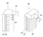
도 1은 본 개시의 일 실시예에 따른 외장 배터리 팩을 나타낸 도면이다.1 is a diagram illustrating an external battery pack according to an embodiment of the present disclosure.
외장 배터리 팩(100)은 전기차량의 운행 중에 전기차량을 충전할 수 있다. 또한 외장 배터리 팩(100)은 전기차량의 운행 중에 전기차량을 구동할 수 있는 전기에너지를 전기차량에 공급할 수 있다.The
외장 배터리 팩(100)은 충방전이 가능한 적어도 하나의 전지셀을 포함하는 배터리 레이어(110)를 포함할 수 있다. 배터리 레이어(110)에 전기에너지가 저장되어있을 수 있다.The
외장 배터리 팩(100)은 배터리 레이어(110)에 접하고, 전기차량의 외형 및 배터리 레이어의 모양에 따라 변형 가능한 탄성 레이어(120)를 포함할 수 있다. 배터리 레이어(110)는 탄성 레이어(120)에 결합되거나 접착될 수 있다. 탄성 레이어(120)에 의하여 외장 배터리 팩(100)과 차량 사이에 공간이 최소화될 수 있다.The
탄성 레이어(120)는 탄성체를 포함할 수 있다. 탄성 레이어(120)의 재질은 다공성 고무 또는 스펀지와 같은 다공성 재질을 포함할 수 있다. 또한 탄성 레이어(120)는 침대의 매트리스와 같이 복수의 스프링에 의하여서 구현될 수 있다.The
외장 배터리 팩(100)은 탄성 레이어(120)에 접하고, 전기차량과 결합할 수 있도록 적어도 일부분이 자성을 띄는 부착 레이어(130)를 포함할 수 있다. 부착 레이어(130)는 복수의 부착부재(131, 132, 133)을 포함할 수 있다. 복수의 부착부재(131, 132, 133) 중 적어도 하나는 자성을 띌 수 있다. 부착 레이어(130)는 자성에 의하여 전기차량에 부착될 수 있다.The
또한 부착 레이어(130)의 적어도 일부는 전자석일 수 있다. 외장 배터리 팩(100)은 부착 레이어(130)의 전자석의 동작을 제어하기 위한 스위치를 포함할 수 있다. 스위치가 'ON'인 경우 부착 레이어(130)의 적어도 일부는 배터리 레이어(110)로부터 전기 에너지를 공급받아 자성을 띌 수 있다. 또한 전자석은 차량의 금속재질에 붙을 수 있다. 또한 스위치가 'OFF'인 부착 레이어(130)의 적어도 일부는 배터리 레이어(110)로부터 전기 에너지를 공급받지 못하여 자성을 잃을 수 있다. 따라서 사용자는 외장 배터리 팩(100)을 차량으로부터 떼어낼 수 있다.In addition, at least a portion of the
부착 레이어(130)의 적어도 일부는 영구 자석일 수 있다. 부착 레이어(130)의 적어도 일부는 유연한 재질의 영구 자석일 수 있다. 따라서 차량의 곡면에 이격을 최소화하면서 붙을 수 있다. 하지만 이에 한정되는 것은 아니며 부착 레이어(130)의 적어도 일부는 유연하지 않은 재질의 영구 자석일 수 있다.At least a portion of the
외장 배터리 팩(100)은 전기차량의 충전구에 결합되는 충전단자(140)를 포함할 수 있다. 충전단자(140)는 배터리 레이어(110)와 전기차량을 연결할 수 있다. 또한 충전단자(140)는 배터리 레이어(110)의 전기에너지를 전기차량에 공급할 수 있다.The
충전단자(140)는 도 1에 기재된 화살표와 같이 상하 또는 좌우로 이동 가능할 수 있다. 또한 충전단자(140)의 길이는 조절될 수 있다. 외장 배터리 팩(100)은 다양한 차량에 결합될 수 있으며, 차량에 따라 충전구의 모양, 위치, 방향, 차량 외관이 다를 수 있다. 충전단자(140)가 상하 또는 좌우로 이동할 수 있고 길이도 조절되므로, 외장 배터리 팩(100)은 다양한 차량에 적응적으로 결합될 수 있다.The charging
전기차량(250)을 충전하기 위한 충전단자(140)의 표준은 다양할 수 있다. 외부 배터리 팩(100)은 컨버터를 포함할 수 있다. 컨버터는 충전단자(140)를 다른 표준에 맞도록 전기적 속성을 변환할 수 있다. 또한 컨버터는 충전단자(140)와 전기차량(250)의 충전구 사이에 위치하여 충전구와 충전단자(140)의 모양이 다르더라도 문제없이 전기차량(250)을 충전하도록 할 수 있다.The standard of the charging
위에서는 부착 레이어(130)가 자성을 띄는 구성에 대하여 설명하였으나 이에 한정되는 것은 아니다. 부착 레이어(130)는 차량과 부착이 가능한 다양한 재질 또는 수단으로 구현될 수 있다.The configuration in which the
외장 배터리 팩(100)은 배터리 레이어(110) 상에 손잡이를 더 포함할 수 있다. 손잡이는 사용자가 외장 배터리 팩(100)을 들고 다니기 위한 용도일 수 있다. 또한 손잡이는 사용자가 외장 배터리 팩(100)을 전기차량으로부터 떼어내기 위한 용도일 수 있다.The
도 2는 본 개시의 일 실시예에 따른 외장 배터리 팩이 차량에 부착된 도면을 나타낸다.2 is a diagram illustrating an external battery pack attached to a vehicle according to an exemplary embodiment of the present disclosure.
도 2는 전기차량(250)을 뒤에서 바라본 도면일 수 있다. 사용자는 전기차량(250)의 배터리에 이상이 있거나 방전되었을 때, 외장 배터리 팩(100)을 차량에 장착할 수 있다. 전기차량(250)은 외장 배터리 팩(100)의 전기에너지를 이용하여 충전소 또는 수리소까지 운행할 수 있다. 또한 전기차량(250)은 외장 배터리 팩(100)의 전기 에너지를 이용하여 모터를 구동하거나, 전기차량(250)의 배터리를 충전할 수 있다. 전기차량(250)은 외장 배터리 팩(100)을 결합한 채로 운행될 수 있다.2 may be a view of the
이미 설명한 바와 같이, 외장 배터리 팩(100)은 배터리 레이어(110), 탄성 레이어(120), 부착 레이어(130) 및 충전단자(140)를 포함할 수 있다.As already described, the
외장 배터리 팩(100)의 충전단자(140)는 전기차량(250)의 충전구에 결합될 수 있다. 충전단자(140)와 충전구는 공극없이 결합되어 수분이 충전단자(140)의 전극에 침투할 수 없다. 따라서 비가 오는 중에도 외장 배터리 팩(100)은 차량의 외부에 결합되어 차량을 충전하거나 구동할 수 있다.The charging
차량의 외면(251)은 굴곡이 있을 수 있다. 또한 차량의 종류에 따라 차량의 외면(251)은 서로 다를 수 있다. 본 개시의 외장 배터리 팩(100)은 모든 차종에 결합될 수 있도록 탄성 레이어(120) 및 부착 레이어(130)의 모양이 변형될 수 있다.The
부착 레이어(130)는 복수의 부착부재(131, 132, 133)를 포함할 수 있다. 복수의 부착부재(131, 132, 133) 각각의 위치 또는 각도는 차량의 외면(251)의 굴곡에 따라 변경될 수 있다. 예를 들어 차량의 외면(251) 중 곡면 부위에 위치한 부착부재(133)는 길이 방향의 중심축을 기준으로 회전할 수 있다. 여기서 길이방향은 차량의 앞뒤방향을 의미할 수 있다. 또한, 차량의 외면(251) 중 오목한 부위에 위치한 부착부재(133)는 부착부재(131)보다 차량 방향으로 이동하여 위치할 수 있다. 복수의 부착부재(131, 132, 133) 중 적어도 하나는 차량과 결합되기 위한 수단을 포함할 수 있다. 예를 들어 복수의 부착부재(131, 132, 133) 중 적어도 하나는 자성을 띠거나, 점착물질을 포함할 수 있다.The
또한, 복수의 부착부재(131, 132, 133)의 형태에 따라 탄성 레이어(120)의 형태는 변형될 수 있다. 이와 같이 부착 레이어(130) 및 탄성 레이어(120)의 형태가 차량의 외면(251)에 따라 변형되므로 차량과 외장 배터리 팩(100)은 이격을 최소화하여 결합될 수 있다. 따라서, 본 개시의 일 실시예에 따른 외장 배터리 팩(100)은 부착 레이어(130) 및 충전단자(140)에 의하여 차량에 견고하게 부착될 수 있다. 외장 배터리 팩(100)은 전기차량에 견고하게 부착되므로, 전기차량이 고속으로 운행 중일지라도 안정적으로 전기에너지를 전기차량에 공급할 수 있다.In addition, the shape of the
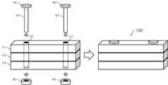
도 3은 본 개시의 일 실시예에 따른 부착 레이어를 나타낸 도면이다.3 is a diagram illustrating an attachment layer according to an embodiment of the present disclosure.
부착 레이어(130)의 부착부재(131, 132, 133)는 긴 막대 형상일 수 있다. 부착부재(131, 132, 133)는 유연한 재질일 수 있다. 복수의 부착부재(131, 132, 133) 중 적어도 하나는 자성을 띄거나, 접착력을 가질 수 있다.The
부착부재(131, 132, 133)는 길이방향에 수직하게 적어도 하나의 관통홀(311, 312)을 형성할 수 있다. 부착부재(131, 132, 133)를 길이 방향에 수직하게 자른 단면은 삼각형 또는 사각형일 수 있다. 예를 들어 단면은, 정삼각형, 직각삼각형, 직사각형 또는 사다리꼴일 수 있다. 하지만 이에 한정되는 것은 아니며 다양한 모양을 가질 수 있다.The
부착 레이어(130)는 복수의 부착부재(131, 132, 133)의 관통홀(311, 312)을 관통하여 복수의 부착부재를 결합시키기 위한 연결부재(321, 322)를 포함할 수 있다. 연결부재(321, 322)는 유연한재질일 수 있다. 예를 들어 연결부재(321, 322)는 끈 또는 고무막대를 포함할 수 있다. 끈은 금속 또는 섬유로 만들어질 수 있다.The
연결부재(321, 322)의 지름은 관통홀(311, 312)의 지름보다 작을 수 있다. 또한, 연결부재(321, 322)의 길이는 관통홀(311, 312)의 길이보다 길 수 있다. 따라서 복수의 부착부재(131, 132, 133)는 연결부재(321, 322)에 의해 연결되어 있으나, 유동적으로 움직일 수 있다.The diameters of the connecting
연결부재(321, 322)는 스토퍼(341, 342, 331, 332)를 포함할 수 있다. 스토퍼(341, 342)는 충전단자(140)에 삽입되어 고정되어 있을 수 있다. 스토퍼(341, 342, 331, 332)는 부착부재(131, 132, 133)가 연결부재(321, 322)에서 빠지지 않도록 할 수 있다.The connecting
도 4는 본 개시의 일 실시예에 따른 부착 레이어를 나타낸 도면이다.4 is a diagram illustrating an attachment layer according to an embodiment of the present disclosure.
도 3에서 부착부재(131, 132, 133)는 긴 막대 형상이었으나 이에 한정되는 것은 아니다. 도 4는 부착 레이어(130)를 차량에 붙이는 방향에서 바라본 사시도이다. 도 4를 참조하면 부착부재는 직육면체 또는 정육면체 형상일 수 있다.In FIG. 3, the
하나의 부착부재는 적어도 2개의 관통홀이 형성되어 있을 수 있다. 즉 하나의 부착부재는 가로 방향의 관통홀 및 세로 방향의 관통홀을 포함할 수 있다. 복수의 부착부재는 가로 방향의 연결부재 및 세로 방향의 연결부재에 의하여 연결될 수 있다. 본 개시의 일 실시예에 따른 부착 레이어(130)는 가로방향 뿐 아니라 세로방향으로 유동성이 생기므로, 굴곡이 있는 차량의 면에 견고하게 부착될 수 있다.One attachment member may have at least two through holes formed therein. That is, one attachment member may include a through hole in a horizontal direction and a through hole in a vertical direction. The plurality of attachment members may be connected by a connecting member in a horizontal direction and a connecting member in a vertical direction. Since the
도 5는 본 개시의 일 실시예에 따른 외장 배터리 팩이 차량에 부착된 도면을 나타낸다.5 illustrates a view in which an external battery pack according to an embodiment of the present disclosure is attached to a vehicle.
도 5는 외장 배터리 팩(100)을 장착한 차량의 단면을 나타낸다.5 shows a cross-section of a vehicle in which the
외장 배터리 팩(100)은 보조 고정부(115)를 더 포함할 수 있다. 보조 고정부(115)는 부착 레이어, 배터리 레이어 또는 탄성 레이어 중 적어도 하나에 결합될 수 있다. 보조 고정부(115)는 외장 배터리 팩(100)이 전기차량(250)에 고정될 수 있도록, 집게를 포함할 수있다. 보조 고정부(115)는 전기차량의 휀더(252)에 고정될 수 있다. 보조 고정부(115)는 차량의 외면(251)에 부착된 부착 레이어(130)를 보조하기 위한 구성일 수 있다. 보조 고정부(115)는 차량의 휀더에 고정되어 외장 배터리 팩(100)이 전기차량(250)에 보다 견고하게 고정될 수 있다.The
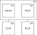
도 6은 본 개시의 일 실시예에 따른 외장 배터리 팩(100)의 제어부를 나타낸 도면이다.6 is a view showing a control unit of the
외장 배터리 팩(100)은 제어부(600)를 포함할 수 있다. 제어부(600)는 프로세서(610) 및 메모리(620)를 포함할 수 있다. 프로세서(610)는 메모리(620)에 저장된 명령어에 기초하여 동작할 수 있다. 또한 프로세서(610)는 메모리(620)에 저장된 데이터들을 처리할 수 있다.The
제어부(600)는 배터리 레이어의 충방전을 제어할 수 있다. 또한 제어부(600)는 전기차량에 대한 제어 신호를 생성할 수 있다.The
외장 배터리 팩(100)은 통신부(630)를 포함할 수 있다. 통신부(630)는 유선 또는 무선통신을 지원할 수 있다. 외장 배터리 팩(100)은 통신부(630)를 통하여 전기차량(250) 또는 사용자 단말기와 통신할 수 있다. 통신부(630)는 제어 신호를 전기차량(250)에 송신할 수 있다. 또한 통신부(630)는 전기차량(250)으로부터 배터리 레이어(110)를 제어하기 위한 신호를 수신할 수 있다.The
외장 배터리 팩(100)은 센서부(640)를 포함할 수 있다. 센서부(640)는 수분감지센서 또는 온도감지센서 등을 포함할 수 있다. 센서부(640)는 주기적으로 수분 또는 온도를 측정을 할 수 있다.The
예를 들어 센서부(640)는 충전단자(140) 근처에 수분감지센서를 더 포함할 수 있다. 제어부(600)는 수분감지센서로부터 측정된 수분 정보가 임계값 이상인 경우, 알람 신호를 생성할 수 있다. 또한 외장 배터리 팩(100)으로부터 전기차량(250)으로 전기 에너지가 공급되지 않도록 제어할 수 있다. 외장 배터리 팩(100)은 외부에 장착되므로 충전단자(140)는 방수가 될 수 있다. 하지만 외장 배터리 팩(100)의 충전단자(140)에 사용자가 의도하지 않은 큰 충격이 가해진 경우, 방수 기능을 상실할 수 있다. 또한 방수 기능의 상실에 의하여 충전단자(140)의 전극이 수분에 노출되는 경우, 화재로 이어질 수 있다. 이러한 문제점을 해결하기 위하여 외장 배터리 팩(100)은 수분감지센서를 이용할 수 있다.For example, the
또한 센서부(640)는 배터리 레이어(110) 상의 온도감지센서를 더 포함할 수 있다. 온도감지센서는 배터리 레이어(110)의 온도를 측정할 수 있다. 제어부(600)는 온도감지센서가 측정한 온도가 임계값 이상인 경우, 알람신호를 생성할 수 있다. 또한, 제어부(600)는 외장 배터리 팩(100)으로부터 전기차량(250)으로 전기 에너지가 공급되지 않도록 제어할 수 있다. 배터리 레이어(110)에 포함된 전지셀은 충격 또는 고온에 의하여 손상될 수 있다. 또한 전지셀은 높은 에너지를 가지고 있으므로, 발화될 가능성이 있다. 제어부(600)는 배터리 레이어(110)가 발화될 가능성이 있는 온도인 경우, 외장 배터리 팩(100)의 동작을 멈출 수 있다. 따라서 외장 배터리 팩(100)이 결합된 전기차량(250)은 안전하게 운행될 수 있다.In addition, the
또한 센서부(640)는 배터리 레이어(110)의 전류 또는 전압을 측정하기 위한 센서를 더 포함할 수 있다. 제어부(600)는 센서부(640)가 측정한 전류 또는 전압이 임계값 이상인 경우, 알람신호를 생성할 수 있다. 또한, 제어부(600)는 외장 배터리 팩(100)으로부터 전기차량(250)으로 전기 에너지가 공급되지 않도록 제어할 수 있다. 또한 제어부(600)는 외장 배터리 팩(100)이 충전되지 않도록 제어할 수 있다. 배터리 레이어(110)에 포함된 전지셀은 과도한 전류로 충전되거 과도한 전류로 방전되는 경우 화재의 가능성이 있다. 또한 전지셀은 높은 에너지를 가지고 있으므로, 발화될 가능성이 있다. 제어부(600)는 배터리 레이어(110)가 발화될 가능성이 있는 전류 또는 전압인 경우, 외장 배터리 팩(100)의 동작을 멈출 수 있다. 따라서 외장 배터리 팩(100)이 결합된 전기차량(250)은 안전하게 운행될 수 있다.In addition, the
임계값은 메모리(620)에 미리 저장되어 있을 수 있다. 하지만 이에 한정되는 것은 아니며 제어부(600)는 통신부(630)를 통하여 임계값을 외부의 장치로부터 수신할 수 있다.The threshold value may be previously stored in the
상술한 바와 같은 알람신호는 통신부(630)를 통하여 전기차량(250), 사용자 단말기, 차량제조사 서버 또는 보험사 서버로 송신될 수 있다. 알람신호를 수신한 사람은 필요한 조치를 취할 수 있다.The alarm signal as described above may be transmitted to the
외장 배터리 팩(100)은 출력부를 더 포함할 수 있다. 제어부(600)에 의하여 생성된 알람신호는 출력부를 통하여 출력될 수 있다. 출력부(840)는 디스플레이 또는 스피커를 포함할 수 있다. 디스플레이는 적어도 하나의 발광소자를 포함할 수 있다. 발광소자는 LED 또는 전구를 포함할 수 있다. 출력부(840)는 빛 또는 소리로 도난 신호를 출력할 수 있다.The
또한 센서부(640)는 위치센서를 더 포함할 수 있다. 제어부(600)는 위치센서를 이용하여 외장 배터리 팩(100)의 위치를 획득할 수 있다. 제어부(600)는 위치를 전기차량(250) 또는 사용자 단말기로 송신할 수 있다. 전기차량(250) 또는 사용자 단말기는 외장 배터리 팩(100)의 위치를 디스플레이에 표시할 수 있다. 사용자는 외장 배터리 팩의 임대업자에게 외장 배터리 팩을 임대하기위한 소정의 인증 과정을 밟을 수 있다. 또한 사용자는 외장 배터리 팩(100)을 임대하여 사용 후 소정의 장소에 둘 수 있다. 외장 배터리 팩(100)의 제어부(600)는 위치센서로부터 수신한 위치정보를 임대업자의 단말기로 송신할 수 있다. 임대업자는 위치정보에 기초하여 외장 배터리 팩(100)을 수거할 수 있다.In addition, the
또한 센서부(640)는 속도센서를 더 포함할 수 있다. 제어부(600)는 속도센서를 이용하여 외장 배터리 팩(100)의 속도를 측정할 수 있다. 외장 배터리 팩(100)이 전기차량(250)에 결합된 경우, 외장 배터리 팩(100)의 속도는 전기차량(250)의 속도를 의미할 수 있다. 외장 배터리 팩(100)은 속도가 임계값 이상인 경우, 배터리 레이어(110)의 전기에너지를 전기차량(250)으로 공급하지 않을 수 있다. 전기차량(250)의 속도가 빠를 수록 배터리 레이어(110)의 방전 속도는 빠를 수 있다. 또한 방전 속도가 빠를 수록 배터리 레이어(110)의 온도는 높아질 수 있으며, 화재의 가능성도 있다. 따라서 외장 배터리 팩(100)은 속도가 지나치게 빠른 경우, 전기차량(250)으로의 전기에너지 공급을 줄일 수 있다. 따라서 외장 배터리 팩(100)은 배터리 레이어(110)의 방전 속도를 낮출 수 있다.In addition, the
도 7은 본 개시의 일 실시예에 따른 외장 배터리 팩의 동작을 설명하기 위한 흐름도이다.7 is a flowchart illustrating an operation of an external battery pack according to an embodiment of the present disclosure.
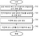
제어부(600)는 외장 배터리 팩(100)이 전기차량(250)에 연결되었는지 여부를 결정할 수 있다.The
본 개시의 일 실시예에 따르면, 제어부(600)는 센서부(640)의 신호에 기초하여 외장 배터리 팩(100)이 전기차량(250)에 연결되었는지 여부를 결정하는 단계(710)를 수행할 수 있다. 예를 들어 센서부(640)는 배터리 레이어(110)의 전류 또는 전압을 측정할 수 있다. 제어부(600)는 센서부(640)의 신호에 기초하여 외장 배터리 팩(100)이 충전되고 있는지 방전되고 있는지 결정할 수 있다. 또한, 제어부(600)는 센서부(640)의 신호에 기초하여 외장 배터리 팩(100)의 미리 결정된 범위 내의 전류로 방전되고 있다면 외장 배터리 팩(100)이 전기차량(250)에 연결되어 있음을 결정할 수 있다.According to an embodiment of the present disclosure, the
또한 본 개시의 일 실시예에 따르면, 제어부(600)는 통신부(630)의 신호에 기초하여 외장 배터리 팩(100)이 전기차량(250)에 연결되어 있는지 여부를 결정할 수 있다. 외장 배터리 팩(100)과 전기차량(250)은 소정의 프로토콜로 통신할 수 있다. 외장 배터리 팩(100)은 전기차량(250)으로부터 수신한 신호에 기초하여 외장 배터리 팩(100)이 전기차량(250)에 연결되어 있음을 결정할 수 있다. 수신한 신호는 전기차량(250)의 식별자, 정상 연결되었음을 나타내는 신호, 전기차량(250)이 충전되고 있음을 나타내는 신호 중 하나를 포함할 수 있다.Also, according to an embodiment of the present disclosure, the
제어부(600)는 외장 배터리 팩(100)이 전기차량(250)에 연결된 것으로 결정된 경우, 전기차량(250)의 내부 배터리 정보를 요청하는 신호를 통신부를 통하여 전기차량에 송신하도록 제어하는 단계(720)를 수행할 수 있다.When it is determined that the
내부 배터리는 전기차량(250)에 기본으로 장착되어 모터를 구동하는 배터리를 의미한다. 내부 배터리 정보는 배터리가 가지고 있는 전기 에너지에 관련된 정보를 나타낼 수 있다. 예를 들어 내부 배터리 정보는 충전량 또는 전압 중 적어도 하나를 포함할 수 있다.The internal battery refers to a battery that is basically installed in the
제어부(600)는 통신부(630)를 통하여 수신된 전기차량의 내부 배터리 정보에 기초하여 저전력 모드 신호를 생성하는 단계(730)를 수행할 수 있다. 저전력 모드 신호는 전기차량(250)이 저전력 모드로 진입하도록 제어하기 위한 신호일 수 있다.The
저전력 모드에 있는 전기차량(250)은 냉온풍기의 동작을 멈추거나, 전기차량(250)의 최대 속도를 낮추거나, 급가속을 방지할 수 있다. 또한, 전기차량(250) 또는 외장 배터리 팩(100)의 비상등을 점멸할 수 있다.The
안전을 위하여 전기차량(250)은 일반적으로 충전을 하는 동시에 운행을 하지 않을 수 있다. 하지만 전기차량(250)은 인증된 외부 배터리 팩(100)에 한하여 충전을 하는 동시에 운행을 허용할 수 있다. 저전력 모드 신호는 외부 배터리 팩(100)이 인증된 외부 배터리임을 나타내는 식별자일 수 있다. 본 개시에 따른 외부 배터리 팩(100)은, 인증되지 않은 외부 배터리 팩(100)이 전기차량(250)을 충전하면서 전기차량(250)이 운행되어, 화재가 생기거나 고속 주행 중에 갑자기 멈추는 것과 같은 위험한 상황을 방지할 수 있다.For safety, the
제어부(600)는 내부 배터리 정보에 포함된 충전량이 임계값 이하인 경우, 저전력 모드 신호를 생성할 수 있다. 또한 제어부(6000는 내부 배터리 정보에 포함된 충전량이 임계값 이상인 경우, 저전력 모드 신호를 생성하지 않을 수 있다. 제어부(600)는 전기차량(250)의 내부 배터리가 방전된 경우에만 저전력 모드로 진입하도록 할 수 있다. 하지만 이에 한정되는 것은 아니다. 제어부(600)는 내부 배터리 정보에 상관없이, 외장 배터리 팩(100)이 전기차량(250)에 연결된 경우, 저전력 모드 신호를 생성할 수 있다.The
제어부(600)는 저전력 모드 신호를 통신부를 통하여 전기차량에 송신하도록 제어하는 단계(740)를 수행할 수 있다. 전기차량(250)은 저전력 모드 신호를 수신하여 저전력 모드에 진입할 수 있다, 또한 전기차량(250)은 외부 배터리 팩(100)에 의하여 충전되는 동시에 운행될 수 있다.The
본 개시의 일 실시예에 따르면, 전기차량(250)은 저전력 모드 신호가 인증된 신호인지 결정할 수 있다. 전기차량(250)은 저전력 모드 신호가 인증된 신호가 아닌 경우 아무런 동작도 하지 않을 수 있다. 전기차량(250)은 저전력 모드 신호가 인증된 신호인 경우, 저전력 모드로 진입할 수 있다.According to an embodiment of the present disclosure, the
본 개시에 따른 외장 배터리 팩(100)은 전기차량(250)에 외장 배터리 팩(100)이 장착된 경우, 전기차량(250)을 저전력 모드로 진입하도록 할 수 있다. 외장 배터리 팩(100)은 저전력모드에 의하여 전기차량(250)의 운행거리를 늘릴 수 있다.The
또한 전기차량(250)이 고속으로 운행되는 경우, 소모전력이 크므로 외장 배터리 팩(100)은 과열될 수 있고 화재의 위험성도 있다. 하지만 외장 배터리 팩(100)은 저전력모드에 의하여 전기차량(250)의 최대속도를 제한하므로 사용자는 전기차량(250)을 안전하게 충전소 또는 수리소까지 운행할 수 있다.In addition, when the
전기차량(250)은 외부 배터리 팩(100)에 의하여 내부 배터리를 충전할 수 있다. 하지만 이에 한정되는 것은 아니다. 전기차량(250)은 외부 배터리 팩(100)으로부터의 전기에너지를 이용하여 직접 모터를 구동할 수 있다.The
제어부(600)는 전기차량(250)의 내부 배터리의 전기에너지보다 배터리 레이어(110)의 전기에너지를 우선적으로 사용하여 전기차량을 구동하도록 제어할 수 있다. 즉, 제어부(600)는 전기차량(250)의 내부 배터리에 전기에너지가 남아 있더라도, 외부 배터리 팩(100)의 전기에너지를 이용하여 전기차량(250)이 운행되도록 제어할 수 있다.The
본 개시에 따르면, 외부 배터리 팩(100)의 전기 에너지를 먼저 소모하도록 하여, 전기차량(250)의 내부 배터리의 추가적인 소모를 줄일 수 있다. 따라서, 사용자는 충전소에서 전기차량(250)의 내부 배터리를 빠르게 충전할 수 있다.According to the present disclosure, the electric energy of the
제어부(600)는 배터리 레이어(110)의 배터리 잔량 정보 및 전기차량(250)의 내부 배터리 잔량 정보 중 적어도 하나에 기초하여 응급 신호를 생성할 수 있다. 예를 들어, 제어부(600)는 배터리 레이어(110)의 배터리 잔량 정보가 제 1 임계값보다 낮거나, 전기차량(250)의 내부 배터리 잔량 정보가 제 2 임계값보다 낮은 경우 응급 신호를 생성할 수 있다. 배터리 잔량 정보가 제 1 임계값보다 낮거나, 전기차량(250)의 내부 배터리 잔량 정보가 제 2 임계값보다 낮은 것은 전기차량(250)이 수 킬로 정도만 운행 가능한 것을 나타낼 수 있다.The
제어부(600)는 가장 가까운 충전소까지의 거리 정보에 더 기초하여 응급 신호를 생성할 수 있다. 즉, 제어부(600)는 위치센서로부터 외장 배터리 팩(100)의 위치를 획득할 수 있다. 외장 배터리 팩(100)이 전기차량(250)과 결합되어 있는 경우, 외장 배터리 팩(100)의 위치는 전기차량(250)의 위치와 동일할 수 있다. 제어부(600)는 데이터베이스 또는 서버에 가장 가까운 주유소의 위치 또는 가장 가까운 주유소까지의 거리 정보를 획득할 수 있다. 제어부(600)는 가장 가까운 충전소까지의 거리 정보가 전기차량(250)의 운행가능 거리보다 큰 경우 응급신호를 생성할 수 있다.The
제어부(600)는 응급 신호를 사용자 단말기 또는 보험사 서버 중 적어도 하나로 송신하도록 통신부를 제어할 수 있다. 사용자는 사용자 단말기에 응급 신호가 표시된 경우, 전화로 도움을 요청할 수 있다. 또한 사용자 단말기의 사용자의 입력에 기초하여 제어부(600)는 보험사 서버로 응급신호를 송신할 수 있다. 제어부(600)는 전기차량(250)의 위치정보를 보험사 서버로 송신할 수 있다. 보험사 서버는 사용자의 보험 내역을 확인할 수 있다. 보험사 서버는 전기차량(250)의 위치로 서비스 기사를 출동시킬 수 있다. 보험사 서버는 제어부(600)로부터 수신된 전기차량(250)의 위치정보를 이용할 수 있다.The
도 8은 본 개시의 일 실시예에 따른 전기차량 충전 시스템의 동작 방법을 나타낸 흐름도이다.8 is a flowchart illustrating a method of operating an electric vehicle charging system according to an embodiment of the present disclosure.
외장 배터리 팩(100)은 전기차량(250)의 운행 중에 전기차량을 충전할 수 있다. 외장 배터리 팩(100)은 전기차량(250)과 소정의 통신 프로토콜을 이용하여 통신할 수 있다. 외장 배터리 팩(100) 및 전기차량(250)은 전기차량 충전 시스템에 포함될 수 있다.The
전기차량 충전 시스템에 대한 설명 중 이미 위에서 설명한 내용은 생략한다. 전기차량 충전 시스템에 대한 설명은 이미 설명한 외장 배터리 팩(100)에 대한 설명과 함께 자세히 설명될 수 있다.In the description of the electric vehicle charging system, the contents already described above will be omitted. A description of the electric vehicle charging system may be described in detail together with the description of the
외장 배터리 팩(100)은 전기차량(250)에 연결되었는지 여부를 결정하는 단계(821)를 수행할 수 있다. 외장 배터리 팩(100)이 전기차량(250)에 연결된 것으로 결정된 경우, 외장 배터리 팩(100)은 외장 배터리 팩(100)에 관련된 정보를 통신부를 통하여 전기차량(250)에 송신하도록 제어하는 단계(831)를 수행할 수 있다.The
외장 배터리 팩(100)에 관련된 정보는 외장 배터리 팩(100)의 충전량 또는 외장 배터리 팩(100)의 식별자 중 적어도 하나를 포함할 수 있다. 전기차량(250)은 외장 배터리 팩에 관련된 정보에 기초하여 외장 배터리 팩(100)이 인증된 외장 배터리 팩인지 여부를 결정하는 단계(822)를 수행할 수 있다. 전기차량(250)은 외장 배터리 팩(100)을 인증된 외장 배터리 팩이 아닌 것으로 결정한 경우, 아무런 동작도 하지 않을 수 있다. 또한 전기차량(250)은 출력부를 이용하여 외장 배터리 팩(100)이 인증된 외장 배터리 팩이 아님을 출력할 수 있다.Information related to the
전기차량(250)이 외장 배터리 팩(100)을 인증된 외장 배터리 팩인 것으로 결정한 경우, 전기차량(250)은 저전력 모드로 진입하는 단계(823)를 수행할 수 있다. 전기차량(260)은 저전력모드에 의하여 전기차량(250)의 운행거리를 늘릴 수 있다. 또한 전기차량(250)이 고속으로 운행되는 경우, 소모전력이 크므로 외장 배터리 팩(100)은 과열될 수 있고 화재의 위험성도 있다. 하지만 외장 배터리 팩(100)은 저전력모드에 의하여 전기차량(250)의 최대속도를 제한하므로 사용자는 전기차량(250)을 안전하게 충전소 또는 수리소까지 운행할 수 있다.When the
전기차량(250)은 외장 배터리 팩의 전기 에너지에 기초하여 전기차량(250)을 구동하도록 제어하는 단계(824)를 수행할 수 있다. 본 개시에 따르면, 외부 배터리 팩(100)의 전기 에너지를 먼저 소모하도록 하여, 전기차량(250)의 내부 배터리의 추가적인 소모를 줄일 수 있다. 따라서, 사용자는 충전소에서 전기차량(250)의 내부 배터리를 빠르게 충전할 수 있다.The
상술한 본 발명의 실시예들은 컴퓨터에서 실행될 수 있는 프로그램으로 작성가능하고, 컴퓨터로 읽을 수 있는 기록매체를 이용하여 상기 프로그램을 동작시키는 범용 디지털 컴퓨터에서 구현될 수 있다. 상기 컴퓨터로 읽을 수 있는 기록매체는 마그네틱 저장매체(예를 들면, 롬, 플로피 디스크, 하드디스크 등), 광학적 판독 매체(예를 들면, 시디롬, 디브이디 등)와 같은 저장매체를 포함한다.The above-described embodiments of the present invention can be written in a program that can be executed on a computer, and can be implemented in a general-purpose digital computer that operates the program using a computer-readable recording medium. The computer-readable recording medium includes a storage medium such as a magnetic storage medium (eg, ROM, floppy disk, hard disk, etc.), and an optical reading medium (eg, CD-ROM, DVD, etc.).
이제까지 다양한 실시예들을 중심으로 살펴보았다. 본 개시가 속하는 기술 분야에서 통상의 지식을 가진 자는 본 발명이 본 발명의 본질적인 특성에서 벗어나지 않는 범위에서 변형된 형태로 구현될 수 있음을 이해할 수 있을 것이다. 그러므로 개시된 실시예들은 한정적인 관점이 아니라 설명적인 관점에서 고려되어야 한다. 본 발명의 범위는 전술한 설명이 아니라 특허청구범위에 나타나 있으며, 그와 동등한 범위 내에 있는 모든 차이점은 본 발명에 포함된 것으로 해석되어야 할 것이다.So far, we have looked at the center of various embodiments. Those of ordinary skill in the art to which the present disclosure pertains will appreciate that the present invention may be implemented in a modified form without departing from the essential characteristics of the present invention. Therefore, the disclosed embodiments should be considered from an illustrative point of view rather than a limiting point of view. The scope of the present invention is shown in the claims rather than the foregoing description, and all differences within the scope equivalent thereto should be construed as being included in the present invention.
Claims (8)
Translated fromKorean충방전이 가능한 적어도 하나의 전지셀을 포함하는 배터리 레이어;
상기 배터리 레이어에 접하고, 상기 전기차량의 외형 및 상기 배터리 레이어의 모양에 따라 변형 가능한 탄성 레이어;
상기 탄성 레이어에 접하고, 상기 전기차량과 결합할 수 있도록 적어도 일부분이 자성을 띄는 부착 레이어;
상기 배터리 레이어와 상기 전기차량을 연결하여 상기 배터리 레이어의 전기 에너지를 상기 전기차량에 공급하고, 상기 전기차량의 충전구에 결합되는 충전 단자;
상기 배터리 레이어의 충방전을 제어하고, 상기 전기차량에 대한 제어 신호를 생성하는 제어부; 및
상기 제어 신호를 상기 전기차량에 송신하고, 상기 전기차량으로부터 상기 배터리 레이어를 제어하기 위한 신호를 수신하고, 상기 전기차량과 유선 또는 무선으로 통신하는 통신부를 포함하고,
상기 제어부는,
상기 배터리 레이어의 배터리 잔량 정보 및 상기 전기차량의 내부 배터리 잔량 정보 중 적어도 하나에 기초하여 응급 신호를 생성하고,
상기 응급 신호를 사용자 단말기 또는 보험사 서버 중 적어도 하나로 송신하도록 상기 통신부를 제어하는 것을 특징으로 하는 외장 배터리 팩.
In the external battery pack for charging the electric vehicle while the electric vehicle is running,
A battery layer including at least one battery cell capable of charging and discharging;
An elastic layer in contact with the battery layer and deformable according to an external shape of the electric vehicle and a shape of the battery layer;
An attachment layer in contact with the elastic layer and at least partially magnetic to be coupled to the electric vehicle;
A charging terminal connected to the battery layer and the electric vehicle to supply electric energy of the battery layer to the electric vehicle, and coupled to a charging port of the electric vehicle;
A control unit controlling charging and discharging of the battery layer and generating a control signal for the electric vehicle; And
And a communication unit for transmitting the control signal to the electric vehicle, receiving a signal for controlling the battery layer from the electric vehicle, and communicating with the electric vehicle by wire or wireless,
The control unit,
An emergency signal is generated based on at least one of information on remaining amount of battery in the battery layer and information on remaining amount of internal battery of the electric vehicle,
An external battery pack, characterized in that controlling the communication unit to transmit the emergency signal to at least one of a user terminal or an insurance company server.
상기 부착 레이어는,
긴 막대 형상이며, 길이방향에 수직하게 적어도 하나의 관통홀을 형성한 복수의 부착부재; 및
상기 복수의 부착부재의 관통홀을 관통하여 상기 복수의 부착부재를 결합시키기 위한 연결부재를 포함하고,
상기 복수의 부착부재 중 적어도 하나는 자성을 띄는 것을 특징으로 하는 외장 배터리 팩.
The method of claim 1,
The attachment layer,
A plurality of attachment members having a long rod shape and forming at least one through hole perpendicular to the length direction; And
A connection member for coupling the plurality of attachment members through the through holes of the plurality of attachment members,
At least one of the plurality of attachment members is an external battery pack, characterized in that the magnetic.
상기 부착 레이어에 결합되고, 상기 외장 배터리 팩이 상기 전기차량에 고정될 수 있도록, 상기 전기차량의 휀더에 고정되는 보조 고정부를 더 포함하는 것을 특징으로 하는 외장 배터리 팩.
The method of claim 1,
An external battery pack, further comprising an auxiliary fixing unit coupled to the attachment layer and fixed to a fender of the electric vehicle so that the external battery pack can be fixed to the electric vehicle.
상기 제어부는,
상기 외장 배터리 팩이 상기 전기차량에 연결되었는지 여부를 결정하고,
상기 외장 배터리 팩이 상기 전기차량에 연결된 것으로 결정된 경우, 상기 전기차량의 내부 배터리 정보를 요청하는 신호를 상기 통신부를 통하여 상기 전기차량에 송신하도록 제어하고,
상기 통신부를 통하여 수신된 상기 전기차량의 내부 배터리 정보에 기초하여 저전력 모드 신호를 생성하고,
상기 저전력 모드 신호를 상기 통신부를 통하여 상기 전기차량에 송신하도록 제어하는 것을 특징으로 하는 외장 배터리 팩.
The method of claim 1,
The control unit,
Determining whether the external battery pack is connected to the electric vehicle,
When it is determined that the external battery pack is connected to the electric vehicle, controlling to transmit a signal requesting internal battery information of the electric vehicle to the electric vehicle through the communication unit,
Generates a low power mode signal based on the internal battery information of the electric vehicle received through the communication unit,
And controlling to transmit the low power mode signal to the electric vehicle through the communication unit.
상기 제어부는,
상기 전기차량의 내부 배터리의 전기에너지보다 상기 배터리 레이어의 전기에너지를 우선적으로 사용하여 상기 전기차량을 구동하도록 제어하는 것을 특징으로 하는 외장 배터리팩.
The method of claim 5,
The control unit,
An external battery pack, characterized in that controlling to drive the electric vehicle by preferentially using electric energy of the battery layer over electric energy of an internal battery of the electric vehicle.
상기 외장 배터리 팩이 상기 전기차량에 연결되었는지 여부를 결정하는 단계;
상기 외장 배터리 팩이 상기 전기차량에 연결된 것으로 결정된 경우, 상기 외장 배터리 팩에 관련된 정보를 통신부를 통하여 상기 전기차량에 송신하도록 제어하는 단계;
상기 전기차량은 상기 외장 배터리 팩에 관련된 정보에 기초하여 상기 외장 배터리 팩이 인증된 외장 배터리 팩인지 여부를 결정하는 단계;
상기 외장 배터리 팩이 인증된 외장 배터리 팩인 것으로 결정한 경우, 상기 전기차량은 저전력 모드로 진입하는 단계; 및
상기 전기차량이 상기 외장 배터리 팩의 전기 에너지에 기초하여 상기 전기차량을 구동하도록 제어하는 단계를 포함하는 것을 특징으로 하는 전기차량 충전 시스템의 동작 방법.
In the operating method of a system for charging an electric vehicle while the electric vehicle is running with an external battery pack,
Determining whether the external battery pack is connected to the electric vehicle;
When it is determined that the external battery pack is connected to the electric vehicle, controlling to transmit information related to the external battery pack to the electric vehicle through a communication unit;
Determining, by the electric vehicle, whether the external battery pack is an authenticated external battery pack based on information related to the external battery pack;
When it is determined that the external battery pack is an authenticated external battery pack, entering the electric vehicle into a low power mode; And
And controlling the electric vehicle to drive the electric vehicle based on the electric energy of the external battery pack.
Priority Applications (1)
| Application Number | Priority Date | Filing Date | Title |
|---|---|---|---|
| KR1020200000092AKR102151908B1 (en) | 2020-01-02 | 2020-01-02 | External battery pack for charging electric vehicle and operation method thereof |
Applications Claiming Priority (1)
| Application Number | Priority Date | Filing Date | Title |
|---|---|---|---|
| KR1020200000092AKR102151908B1 (en) | 2020-01-02 | 2020-01-02 | External battery pack for charging electric vehicle and operation method thereof |
Publications (1)
| Publication Number | Publication Date |
|---|---|
| KR102151908B1true KR102151908B1 (en) | 2020-09-03 |
Family
ID=72450348
Family Applications (1)
| Application Number | Title | Priority Date | Filing Date |
|---|---|---|---|
| KR1020200000092AActiveKR102151908B1 (en) | 2020-01-02 | 2020-01-02 | External battery pack for charging electric vehicle and operation method thereof |
Country Status (1)
| Country | Link |
|---|---|
| KR (1) | KR102151908B1 (en) |
Cited By (1)
| Publication number | Priority date | Publication date | Assignee | Title |
|---|---|---|---|---|
| WO2024135905A1 (en)* | 2022-12-23 | 2024-06-27 | 주식회사 젠트로피 | Battery pack double safety device using nfc authentication and method for supplying power to electric vehicle by using same |
Citations (6)
| Publication number | Priority date | Publication date | Assignee | Title |
|---|---|---|---|---|
| US4277526A (en)* | 1978-01-16 | 1981-07-07 | The Standard Products Company | Protective and decorative molding having foam-filled channel |
| KR200284006Y1 (en)* | 2002-04-22 | 2002-07-31 | 정영호 | carrying supporter for a car |
| KR20130078351A (en)* | 2011-12-30 | 2013-07-10 | 넥스콘 테크놀러지 주식회사 | Auto guide vehicle battery management method use wireless communication |
| KR101704568B1 (en)* | 2015-09-07 | 2017-02-08 | 현대자동차주식회사 | Battery for electric vehicle and method of controlling the same |
| KR20180047896A (en)* | 2016-11-01 | 2018-05-10 | 한국과학기술연구원 | External battery pack for driving electric vehicle and method using the same |
| JP2019140879A (en)* | 2018-02-15 | 2019-08-22 | 三菱自動車工業株式会社 | External charger and vehicle management system |
- 2020
- 2020-01-02KRKR1020200000092Apatent/KR102151908B1/enactiveActive
Patent Citations (6)
| Publication number | Priority date | Publication date | Assignee | Title |
|---|---|---|---|---|
| US4277526A (en)* | 1978-01-16 | 1981-07-07 | The Standard Products Company | Protective and decorative molding having foam-filled channel |
| KR200284006Y1 (en)* | 2002-04-22 | 2002-07-31 | 정영호 | carrying supporter for a car |
| KR20130078351A (en)* | 2011-12-30 | 2013-07-10 | 넥스콘 테크놀러지 주식회사 | Auto guide vehicle battery management method use wireless communication |
| KR101704568B1 (en)* | 2015-09-07 | 2017-02-08 | 현대자동차주식회사 | Battery for electric vehicle and method of controlling the same |
| KR20180047896A (en)* | 2016-11-01 | 2018-05-10 | 한국과학기술연구원 | External battery pack for driving electric vehicle and method using the same |
| JP2019140879A (en)* | 2018-02-15 | 2019-08-22 | 三菱自動車工業株式会社 | External charger and vehicle management system |
Cited By (3)
| Publication number | Priority date | Publication date | Assignee | Title |
|---|---|---|---|---|
| WO2024135905A1 (en)* | 2022-12-23 | 2024-06-27 | 주식회사 젠트로피 | Battery pack double safety device using nfc authentication and method for supplying power to electric vehicle by using same |
| KR20240100922A (en)* | 2022-12-23 | 2024-07-02 | 주식회사 젠트로피 | Battery pack double safety device using nfc authentication and power supply method of electric vehicle using the same |
| KR102760660B1 (en)* | 2022-12-23 | 2025-02-03 | 주식회사 젠트로피 | Battery pack double safety device using nfc authentication and power supply method of electric vehicle using the same |
Similar Documents
| Publication | Publication Date | Title |
|---|---|---|
| CN112793429B (en) | Power supply device, vehicle having the same, and control method thereof | |
| CN108349403B (en) | Method and charger for charging a traction energy store of an electrically driven vehicle | |
| CN100500466C (en) | Automatic management method for battery pack air filter | |
| CN103568858A (en) | Vehicle battery charging system and method | |
| JP6790474B2 (en) | Secondary battery monitoring device, battery system, secondary battery protection system, vehicle | |
| KR102368304B1 (en) | Battery pack, method for controlling and driving system of electro-mechanical apparatus having the same | |
| JP2013040556A (en) | Parking assist for vehicle equipped for wireless vehicle charging | |
| JP5154154B2 (en) | Vehicle power supply | |
| WO2018045904A1 (en) | Charging control method, device, and system, and storage medium | |
| JP7432859B2 (en) | Certification method for energy storage pack, energy storage pack, charging device, electric vehicle, and control device for electric vehicle | |
| KR20120012652A (en) | Charging system of electric vehicle and its charging method | |
| EP3246215A1 (en) | Vehicular starter battery management system | |
| US20120109437A1 (en) | Industrial vehicle | |
| JP2013115929A (en) | Charging auxiliary device | |
| KR102151908B1 (en) | External battery pack for charging electric vehicle and operation method thereof | |
| KR101769648B1 (en) | Add-on communication apparatus attached to in-cable charging control apparatus and method thereof | |
| JP2018037193A (en) | Temperature raising system of battery | |
| KR101932066B1 (en) | Device for emergency signaling from a vehicle, system for emergency signaling and method of operation | |
| CN104097585B (en) | For the emergency starting device of automobile and the emergency starting method of automobile and automobile | |
| EP2361827A2 (en) | Electric motorcycle | |
| CN116766938A (en) | Vehicle collision safety protection systems, methods, vehicles and media | |
| CN205901350U (en) | Battery management system for starting batteries in vehicles | |
| KR20190052208A (en) | Server, vehicle and controlling method thereof | |
| CN112389275A (en) | Safety control method and device based on electric drive active heating mode | |
| KR20170045573A (en) | Apparatus and method for controlling power of vehicle |
Legal Events
| Date | Code | Title | Description |
|---|---|---|---|
| PA0109 | Patent application | St.27 status event code:A-0-1-A10-A12-nap-PA0109 | |
| PA0201 | Request for examination | St.27 status event code:A-1-2-D10-D11-exm-PA0201 | |
| PA0302 | Request for accelerated examination | St.27 status event code:A-1-2-D10-D17-exm-PA0302 St.27 status event code:A-1-2-D10-D16-exm-PA0302 | |
| D13-X000 | Search requested | St.27 status event code:A-1-2-D10-D13-srh-X000 | |
| D14-X000 | Search report completed | St.27 status event code:A-1-2-D10-D14-srh-X000 | |
| PE0902 | Notice of grounds for rejection | St.27 status event code:A-1-2-D10-D21-exm-PE0902 | |
| E13-X000 | Pre-grant limitation requested | St.27 status event code:A-2-3-E10-E13-lim-X000 | |
| P11-X000 | Amendment of application requested | St.27 status event code:A-2-2-P10-P11-nap-X000 | |
| P13-X000 | Application amended | St.27 status event code:A-2-2-P10-P13-nap-X000 | |
| P22-X000 | Classification modified | St.27 status event code:A-2-2-P10-P22-nap-X000 | |
| E701 | Decision to grant or registration of patent right | ||
| PE0701 | Decision of registration | St.27 status event code:A-1-2-D10-D22-exm-PE0701 | |
| GRNT | Written decision to grant | ||
| PR0701 | Registration of establishment | St.27 status event code:A-2-4-F10-F11-exm-PR0701 | |
| PR1002 | Payment of registration fee | St.27 status event code:A-2-2-U10-U11-oth-PR1002 Fee payment year number:1 | |
| PG1601 | Publication of registration | St.27 status event code:A-4-4-Q10-Q13-nap-PG1601 | |
| PR1001 | Payment of annual fee | St.27 status event code:A-4-4-U10-U11-oth-PR1001 Fee payment year number:4 | |
| R18-X000 | Changes to party contact information recorded | St.27 status event code:A-5-5-R10-R18-oth-X000 | |
| PR1001 | Payment of annual fee | St.27 status event code:A-4-4-U10-U11-oth-PR1001 Fee payment year number:5 | |
| PR1001 | Payment of annual fee | St.27 status event code:A-4-4-U10-U11-oth-PR1001 Fee payment year number:6 |