KR102150879B1 - Stereo lithography 3d printer comprising floating solution for reducing resin usage - Google Patents
Stereo lithography 3d printer comprising floating solution for reducing resin usageDownload PDFInfo
- Publication number
- KR102150879B1 KR102150879B1KR1020190002935AKR20190002935AKR102150879B1KR 102150879 B1KR102150879 B1KR 102150879B1KR 1020190002935 AKR1020190002935 AKR 1020190002935AKR 20190002935 AKR20190002935 AKR 20190002935AKR 102150879 B1KR102150879 B1KR 102150879B1
- Authority
- KR
- South Korea
- Prior art keywords
- resin
- floating solution
- build platform
- water tank
- printer
- Prior art date
- Legal status (The legal status is an assumption and is not a legal conclusion. Google has not performed a legal analysis and makes no representation as to the accuracy of the status listed.)
- Active
Links
- 239000011347resinSubstances0.000titleclaimsabstractdescription141
- 229920005989resinPolymers0.000titleclaimsabstractdescription141
- 238000007667floatingMethods0.000titleclaimsabstractdescription93
- 238000001459lithographyMethods0.000title1
- XLYOFNOQVPJJNP-UHFFFAOYSA-NwaterSubstancesOXLYOFNOQVPJJNP-UHFFFAOYSA-N0.000claimsabstractdescription66
- 230000003287optical effectEffects0.000claimsabstractdescription20
- 230000001678irradiating effectEffects0.000claimsabstractdescription4
- PEDCQBHIVMGVHV-UHFFFAOYSA-NGlycerineChemical compoundOCC(O)COPEDCQBHIVMGVHV-UHFFFAOYSA-N0.000claimsdescription39
- 235000011187glycerolNutrition0.000claimsdescription19
- 238000000034methodMethods0.000claimsdescription14
- 150000003839saltsChemical class0.000claimsdescription11
- 230000005484gravityEffects0.000claimsdescription4
- AGBQKNBQESQNJD-ZETCQYMHSA-N(S)-lipoic acidChemical compoundOC(=O)CCCC[C@H]1CCSS1AGBQKNBQESQNJD-ZETCQYMHSA-N0.000claims1
- 238000010586diagramMethods0.000description8
- 230000000903blocking effectEffects0.000description3
- 238000005516engineering processMethods0.000description3
- 239000011521glassSubstances0.000description3
- 238000004519manufacturing processMethods0.000description3
- 238000002156mixingMethods0.000description3
- NRZZLYODXDSLEK-UHFFFAOYSA-N(6-ethoxy-6-oxohexyl) 3,5-diacetamido-2,4,6-triiodobenzoateChemical compoundCCOC(=O)CCCCCOC(=O)C1=C(I)C(NC(C)=O)=C(I)C(NC(C)=O)=C1INRZZLYODXDSLEK-UHFFFAOYSA-N0.000description2
- 239000004925Acrylic resinSubstances0.000description2
- 229920000178Acrylic resinPolymers0.000description2
- 239000011248coating agentSubstances0.000description2
- 238000000576coating methodMethods0.000description2
- 239000002184metalSubstances0.000description2
- 2380000101463D printingMethods0.000description1
- 230000015572biosynthetic processEffects0.000description1
- 239000000470constituentSubstances0.000description1
- 230000003247decreasing effectEffects0.000description1
- 230000032798delaminationEffects0.000description1
- 230000000694effectsEffects0.000description1
- JEIPFZHSYJVQDO-UHFFFAOYSA-Niron(III) oxideInorganic materialsO=[Fe]O[Fe]=OJEIPFZHSYJVQDO-UHFFFAOYSA-N0.000description1
- 239000007788liquidSubstances0.000description1
- 239000000463materialSubstances0.000description1
- 238000012986modificationMethods0.000description1
- 230000004048modificationEffects0.000description1
- 238000007639printingMethods0.000description1
- 239000000047productSubstances0.000description1
- 238000003756stirringMethods0.000description1
- 239000013589supplementSubstances0.000description1
Images


Classifications
- B—PERFORMING OPERATIONS; TRANSPORTING
- B29—WORKING OF PLASTICS; WORKING OF SUBSTANCES IN A PLASTIC STATE IN GENERAL
- B29C—SHAPING OR JOINING OF PLASTICS; SHAPING OF MATERIAL IN A PLASTIC STATE, NOT OTHERWISE PROVIDED FOR; AFTER-TREATMENT OF THE SHAPED PRODUCTS, e.g. REPAIRING
- B29C64/00—Additive manufacturing, i.e. manufacturing of three-dimensional [3D] objects by additive deposition, additive agglomeration or additive layering, e.g. by 3D printing, stereolithography or selective laser sintering
- B29C64/30—Auxiliary operations or equipment
- B29C64/307—Handling of material to be used in additive manufacturing
- B29C64/321—Feeding
- B—PERFORMING OPERATIONS; TRANSPORTING
- B29—WORKING OF PLASTICS; WORKING OF SUBSTANCES IN A PLASTIC STATE IN GENERAL
- B29C—SHAPING OR JOINING OF PLASTICS; SHAPING OF MATERIAL IN A PLASTIC STATE, NOT OTHERWISE PROVIDED FOR; AFTER-TREATMENT OF THE SHAPED PRODUCTS, e.g. REPAIRING
- B29C64/00—Additive manufacturing, i.e. manufacturing of three-dimensional [3D] objects by additive deposition, additive agglomeration or additive layering, e.g. by 3D printing, stereolithography or selective laser sintering
- B29C64/10—Processes of additive manufacturing
- B29C64/106—Processes of additive manufacturing using only liquids or viscous materials, e.g. depositing a continuous bead of viscous material
- B29C64/124—Processes of additive manufacturing using only liquids or viscous materials, e.g. depositing a continuous bead of viscous material using layers of liquid which are selectively solidified
- B29C64/129—Processes of additive manufacturing using only liquids or viscous materials, e.g. depositing a continuous bead of viscous material using layers of liquid which are selectively solidified characterised by the energy source therefor, e.g. by global irradiation combined with a mask
- B29C64/135—Processes of additive manufacturing using only liquids or viscous materials, e.g. depositing a continuous bead of viscous material using layers of liquid which are selectively solidified characterised by the energy source therefor, e.g. by global irradiation combined with a mask the energy source being concentrated, e.g. scanning lasers or focused light sources
- B—PERFORMING OPERATIONS; TRANSPORTING
- B29—WORKING OF PLASTICS; WORKING OF SUBSTANCES IN A PLASTIC STATE IN GENERAL
- B29C—SHAPING OR JOINING OF PLASTICS; SHAPING OF MATERIAL IN A PLASTIC STATE, NOT OTHERWISE PROVIDED FOR; AFTER-TREATMENT OF THE SHAPED PRODUCTS, e.g. REPAIRING
- B29C64/00—Additive manufacturing, i.e. manufacturing of three-dimensional [3D] objects by additive deposition, additive agglomeration or additive layering, e.g. by 3D printing, stereolithography or selective laser sintering
- B29C64/20—Apparatus for additive manufacturing; Details thereof or accessories therefor
- B29C64/205—Means for applying layers
- B—PERFORMING OPERATIONS; TRANSPORTING
- B29—WORKING OF PLASTICS; WORKING OF SUBSTANCES IN A PLASTIC STATE IN GENERAL
- B29C—SHAPING OR JOINING OF PLASTICS; SHAPING OF MATERIAL IN A PLASTIC STATE, NOT OTHERWISE PROVIDED FOR; AFTER-TREATMENT OF THE SHAPED PRODUCTS, e.g. REPAIRING
- B29C64/00—Additive manufacturing, i.e. manufacturing of three-dimensional [3D] objects by additive deposition, additive agglomeration or additive layering, e.g. by 3D printing, stereolithography or selective laser sintering
- B29C64/20—Apparatus for additive manufacturing; Details thereof or accessories therefor
- B29C64/255—Enclosures for the building material, e.g. powder containers
- B—PERFORMING OPERATIONS; TRANSPORTING
- B29—WORKING OF PLASTICS; WORKING OF SUBSTANCES IN A PLASTIC STATE IN GENERAL
- B29C—SHAPING OR JOINING OF PLASTICS; SHAPING OF MATERIAL IN A PLASTIC STATE, NOT OTHERWISE PROVIDED FOR; AFTER-TREATMENT OF THE SHAPED PRODUCTS, e.g. REPAIRING
- B29C64/00—Additive manufacturing, i.e. manufacturing of three-dimensional [3D] objects by additive deposition, additive agglomeration or additive layering, e.g. by 3D printing, stereolithography or selective laser sintering
- B29C64/40—Structures for supporting 3D objects during manufacture and intended to be sacrificed after completion thereof
- B—PERFORMING OPERATIONS; TRANSPORTING
- B33—ADDITIVE MANUFACTURING TECHNOLOGY
- B33Y—ADDITIVE MANUFACTURING, i.e. MANUFACTURING OF THREE-DIMENSIONAL [3-D] OBJECTS BY ADDITIVE DEPOSITION, ADDITIVE AGGLOMERATION OR ADDITIVE LAYERING, e.g. BY 3-D PRINTING, STEREOLITHOGRAPHY OR SELECTIVE LASER SINTERING
- B33Y10/00—Processes of additive manufacturing
- B—PERFORMING OPERATIONS; TRANSPORTING
- B33—ADDITIVE MANUFACTURING TECHNOLOGY
- B33Y—ADDITIVE MANUFACTURING, i.e. MANUFACTURING OF THREE-DIMENSIONAL [3-D] OBJECTS BY ADDITIVE DEPOSITION, ADDITIVE AGGLOMERATION OR ADDITIVE LAYERING, e.g. BY 3-D PRINTING, STEREOLITHOGRAPHY OR SELECTIVE LASER SINTERING
- B33Y30/00—Apparatus for additive manufacturing; Details thereof or accessories therefor
- B—PERFORMING OPERATIONS; TRANSPORTING
- B33—ADDITIVE MANUFACTURING TECHNOLOGY
- B33Y—ADDITIVE MANUFACTURING, i.e. MANUFACTURING OF THREE-DIMENSIONAL [3-D] OBJECTS BY ADDITIVE DEPOSITION, ADDITIVE AGGLOMERATION OR ADDITIVE LAYERING, e.g. BY 3-D PRINTING, STEREOLITHOGRAPHY OR SELECTIVE LASER SINTERING
- B33Y40/00—Auxiliary operations or equipment, e.g. for material handling
- B—PERFORMING OPERATIONS; TRANSPORTING
- B33—ADDITIVE MANUFACTURING TECHNOLOGY
- B33Y—ADDITIVE MANUFACTURING, i.e. MANUFACTURING OF THREE-DIMENSIONAL [3-D] OBJECTS BY ADDITIVE DEPOSITION, ADDITIVE AGGLOMERATION OR ADDITIVE LAYERING, e.g. BY 3-D PRINTING, STEREOLITHOGRAPHY OR SELECTIVE LASER SINTERING
- B33Y70/00—Materials specially adapted for additive manufacturing
- B—PERFORMING OPERATIONS; TRANSPORTING
- B29—WORKING OF PLASTICS; WORKING OF SUBSTANCES IN A PLASTIC STATE IN GENERAL
- B29C—SHAPING OR JOINING OF PLASTICS; SHAPING OF MATERIAL IN A PLASTIC STATE, NOT OTHERWISE PROVIDED FOR; AFTER-TREATMENT OF THE SHAPED PRODUCTS, e.g. REPAIRING
- B29C64/00—Additive manufacturing, i.e. manufacturing of three-dimensional [3D] objects by additive deposition, additive agglomeration or additive layering, e.g. by 3D printing, stereolithography or selective laser sintering
- B29C64/20—Apparatus for additive manufacturing; Details thereof or accessories therefor
- B29C64/245—Platforms or substrates
- B—PERFORMING OPERATIONS; TRANSPORTING
- B29—WORKING OF PLASTICS; WORKING OF SUBSTANCES IN A PLASTIC STATE IN GENERAL
- B29C—SHAPING OR JOINING OF PLASTICS; SHAPING OF MATERIAL IN A PLASTIC STATE, NOT OTHERWISE PROVIDED FOR; AFTER-TREATMENT OF THE SHAPED PRODUCTS, e.g. REPAIRING
- B29C64/00—Additive manufacturing, i.e. manufacturing of three-dimensional [3D] objects by additive deposition, additive agglomeration or additive layering, e.g. by 3D printing, stereolithography or selective laser sintering
- B29C64/30—Auxiliary operations or equipment
Landscapes
- Chemical & Material Sciences (AREA)
- Engineering & Computer Science (AREA)
- Materials Engineering (AREA)
- Manufacturing & Machinery (AREA)
- Physics & Mathematics (AREA)
- Optics & Photonics (AREA)
- Mechanical Engineering (AREA)
Abstract
Translated fromKoreanDescription
Translated fromKorean아래의 설명은 레진 사용량 절감을 위한 플로팅 용액을 포함하는 SLA 3D 프린터에 관한 것이다.The following description relates to an SLA 3D printer including a floating solution for reducing resin usage.
SLA 방식은 미국의 3D SYSTEM 사에서 개발한 방식으로, 출력 소재로써 광경화성 레진(resin)을 사용한다. 광경화성 레진은 평소에 물과 같은 액체 상태지만, 레이저 등 특수한 빛에 닿으면 경화되는 성질을 가진 플라스틱의 일종이다. 즉, SLA 방식은 레이저와 스캐너에서 출력되는 레이저를 통해 광경화성 레진을 경화시키고, 이를 반복하여 3D 형상물을 만드는 방식을 말한다.The SLA method is a method developed by 3D SYSTEM in the United States, and uses photocurable resin as an output material. Photocurable resins are usually in a liquid state like water, but are a kind of plastic that hardens when exposed to special light such as a laser. That is, the SLA method refers to a method of making a 3D shape by curing a photocurable resin through a laser and a laser output from a scanner, and repeating this.
기존 SLA 3D 프린터는 수조에 레진을 가득 채운 상태로 경화 작업을 수행하면서 3D 형상을 출력한다. 대면적일수록 대량의 레진이 필요하며, 초기 운용을 위한 레진 비용은 매우 고가이다. 예를 들어, 3D SYSTEMS ProX 950 기준으로, 초기 운용 비용이 2억원 이상 필요하다. 실제, 수조의 레진은 표면 부분만 실제 프린팅에 사용된다. 또한, 다른 종류의 레진을 사용하고자 할 경우, 수조 내측에 레진을 모두 교체해야 한다는 문제가 있었다.Existing SLA 3D printers print 3D shapes while performing curing in a state full of resin in a water tank. The larger the area, the more resin is required, and the resin cost for initial operation is very expensive. For example, based on 3D SYSTEMS ProX 950, the initial operation cost is more than 200 million won. Actually, only the surface part of the resin in the tank is used for actual printing. In addition, if you want to use a different type of resin, there is a problem that all of the resin must be replaced inside the tank.
SLA 3D 프린터에 있어서, 초기 운용 비용 및 사용 비용 등을 줄이기 위한 기술이 요구되는 실정이다.In the SLA 3D printer, technology is required to reduce initial operation cost and usage cost.
전술한 배경기술은 발명자가 본 발명의 도출과정에서 보유하거나 습득한 것으로서, 반드시 본 발명의 출원 전에 일반 공중에 공개된 공지기술이라고 할 수는 없다.The above-described background technology is possessed or acquired by the inventor in the process of deriving the present invention, and is not necessarily a known technology disclosed to the general public prior to filing the present invention.
일 실시 예에 따른 목적은 수조 내측의 대부분을 레진과 혼합되지 않으며, 레진보다 밀도가 높은 플로팅 용액으로 채움으로써, 초기 운용 비용 및 사용 비용을 획기적으로 감소시킬 수 있는 SLA 3D 프린터를 제공하는 것이다.An object according to an embodiment is to provide an SLA 3D printer that is not mixed with resin and can significantly reduce initial operating cost and usage cost by filling a floating solution having a higher density than resin.
일 실시 예에 따른 레진 사용량 절감을 위한 플로팅 용액을 포함하는 SLA 3D 프린터는, 메인 프레임; 상기 메인 프레임 내측에 구비되는 수조; 상기 수조를 따라 연직 방향으로 슬라이딩 가능한 빌드 플랫폼; 상기 메인 프레임의 상측에 구비되고, 상기 빌드 플랫폼으로 레이저 빔을 조사하는 광학부; 상기 수조의 내측에 마련되는 레진; 및 상기 수조의 내측에 마련되고, 상기 레진과 혼합되지 않으며, 상기 레진 보다 밀도가 높고, 상기 레진을 지지하는 플로팅 용액을 포함할 수 있다.An SLA 3D printer including a floating solution for reducing resin usage according to an embodiment includes: a main frame; A water tank provided inside the main frame; A build platform slidable in a vertical direction along the water tank; An optical unit provided on the upper side of the main frame and irradiating a laser beam to the build platform; A resin provided inside the tank; And a floating solution provided inside the tank, not mixed with the resin, having a higher density than the resin, and supporting the resin.
상기 빌드 플랫폼은 연직 방향으로 슬라이딩하여, 상기 레진 및 플로팅 용액의 경계를 통과하고, 상기 레진 및 플로팅 용액은 중력에 의해 서로 분리될 수 있다.The build platform slides in a vertical direction, passes through the boundary between the resin and the floating solution, and the resin and the floating solution may be separated from each other by gravity.
상기 플로팅 용액은, 소금 또는 글리세린을 포함할 수 있다.The floating solution may contain salt or glycerin.
상기 플로팅 용액은, 글리세린 99 중량% 이상을 포함하고, 탈포(defoamation) 작업이 완료된 상태로 상기 수조 내측에 마련될 수 있다.The floating solution may contain 99% by weight or more of glycerin, and may be provided inside the water tank in a state in which a defoamation operation is completed.
상기 플로팅 용액은, 탈포(defoamation) 작업이 완료된 상태로 상기 수조의 내측에 마련될 수 있다.The floating solution may be provided inside the water tank in a state in which a defoamation operation is completed.
일 실시 예에 따른 레진 사용량 절감을 위한 플로팅 용액을 포함하는 SLA 3D 프린터는 수조 내측에 플로팅 마련시킴으로써, 초기 운용 비용 및 사용 비용을 획기적으로 감소시킬 수 있다.The SLA 3D printer including a floating solution for reducing the amount of resin used according to an exemplary embodiment may be provided to float inside the tank, thereby significantly reducing initial operating cost and usage cost.
또한, 레진 사용량 절감을 위한 플로팅 용액을 포함하는 SLA 3D 프린터의 플로팅 용액은 밀도 및 점도가 높아, 빌드 플렛폼이 하강하는 동안 크게 흔들리지 않을 수 있으며, 레진을 안정적으로 지지할 수 있다.In addition, the floating solution of the SLA 3D printer, which includes a floating solution for reducing the amount of resin used, has high density and viscosity, so that the build platform may not shake significantly while descending, and the resin can be stably supported.
또한, 레진 사용량 절감을 위한 플로팅 용액을 포함하는 SLA 3D 프린터는 다른 종류의 레진을 사용하고자 할 경우, 기존에 수조 내측에 마련된 레진과 플로팅 용액의 상단부만을 수조 내측으로부터 외부로 제거하고, 다른 종류의 레진을 수조 내측으로 공급하는 방식으로, 레진 교체 비용을 크게 절감할 수 있다.In addition, the SLA 3D printer that includes a floating solution to reduce the amount of resin used is to remove only the upper part of the resin and floating solution previously prepared inside the tank from the inside to the outside when using a different type of resin. By supplying the resin to the inside of the tank, the cost of replacing the resin can be greatly reduced.
본 명세서에 첨부되는 다음의 도면들은 본 발명의 바람직한 일 실시예를 예시하는 것이며, 발명의 상세한 설명과 함께 본 발명의 기술적 사상을 더욱 이해시키는 역할을 하는 것이므로, 본 발명은 그러한 도면에 기재된 사항에만 한정되어 해석되어서는 아니 된다.
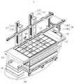
도 1은 일 실시 예에 따른 레진 사용량 절감을 위한 플로팅 용액을 포함하는 SLA 3D 프린터를 개략적으로 나타내는 도면이다.
도 2는 일 실시 예에 따른 레진 사용량 절감을 위한 플로팅 용액을 포함하는 SLA 3D 프린터의 빌드 플랫폼이 연직 방향으로 슬라이딩 하는 모습을 개략적으로 나타내는 도면이다.
도 3은 일 실시 예에 따른 레진 사용량 절감을 위한 플로팅 용액을 포함하는 SLA 3D 프린터의 리코터가 수평 방향으로 슬라이딩하는 모습을 개략적으로 나타내는 도면이다.
도 4는 일 실시 예에 따른 레진 사용량 절감을 위한 플로팅 용액을 포함하는 SLA 3D 프린터를 나타내는 사시도이다.
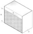
도 5는 일 실시 예에 따른 수조 내측에 레진 및 플로팅 용액이 마련되어 있는 모습을 도시한 단면 사시도이다.
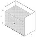
도 6은 일 실시 예에 따른 수조 내측으로부터 레진 및 플로팅 용액의 상단부가 외부로 제거된 모습을 도시한 단면 사시도이다.
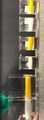
도 7은 일 실시 예에 따른 실험군들을 나타내는 도면이다.
도 8은 도 7의 실험군들 각각을 유리막대로 휘저은 후, 혼합이 일어난 경계면을 나타내는 도면이다.The following drawings attached to the present specification illustrate a preferred embodiment of the present invention, and serve to further understand the technical idea of the present invention together with the detailed description of the present invention, so the present invention is limited to the matters described in such drawings. It is limited and should not be interpreted.
1 is a view schematically showing an SLA 3D printer including a floating solution for reducing the amount of resin used according to an embodiment.
FIG. 2 is a diagram schematically illustrating a state in which a build platform of an SLA 3D printer including a floating solution for reducing resin usage according to an exemplary embodiment slides in a vertical direction.
3 is a diagram schematically illustrating a state in which a recoater of an SLA 3D printer including a floating solution for reducing the amount of resin used according to an embodiment slides in a horizontal direction.
4 is a perspective view illustrating an SLA 3D printer including a floating solution for reducing resin usage according to an exemplary embodiment.
5 is a cross-sectional perspective view showing a state in which a resin and a floating solution are provided inside a water tank according to an exemplary embodiment.
6 is a cross-sectional perspective view illustrating a state in which upper ends of a resin and a floating solution are removed from the inside of a water tank according to an embodiment.
7 is a diagram showing experimental groups according to an embodiment.
FIG. 8 is a diagram showing an interface in which mixing occurs after each of the experimental groups of FIG. 7 is stirred with a glass rod.
이하, 실시 예들을 예시적인 도면을 통해 상세하게 설명한다. 각 도면의 구성요소들에 참조부호를 부가함에 있어서, 동일한 구성요소들에 대해서는 비록 다른 도면상에 표시되더라도 가능한 한 동일한 부호를 가지도록 하고 있음에 유의해야 한다. 또한, 실시 예를 설명함에 있어, 관련된 공지 구성 또는 기능에 대한 구체적인 설명이 실시 예에 대한 이해를 방해한다고 판단되는 경우에는 그 상세한 설명은 생략한다.Hereinafter, embodiments will be described in detail through exemplary drawings. In adding reference numerals to elements of each drawing, it should be noted that the same elements are assigned the same numerals as possible even if they are indicated on different drawings. In addition, in describing the embodiment, if it is determined that a detailed description of a related known configuration or function interferes with the understanding of the embodiment, a detailed description thereof will be omitted.
또한, 실시 예의 구성 요소를 설명하는 데 있어서, 제 1, 제 2, A, B, (a), (b) 등의 용어를 사용할 수 있다. 이러한 용어는 그 구성 요소를 다른 구성 요소와 구별하기 위한 것일 뿐, 그 용어에 의해 해당 구성 요소의 본질이나 차례 또는 순서 등이 한정되지 않는다. 어떤 구성 요소가 다른 구성요소에 "연결", "결합" 또는 "접속"된다고 기재된 경우, 그 구성 요소는 그 다른 구성요소에 직접적으로 연결되거나 접속될 수 있지만, 각 구성 요소 사이에 또 다른 구성 요소가 "연결", "결합" 또는 "접속"될 수도 있다고 이해되어야 할 것이다.In addition, in describing the constituent elements of the embodiment, terms such as first, second, A, B, (a) and (b) may be used. These terms are only used to distinguish the component from other components, and the nature, order, or order of the component is not limited by the term. When a component is described as being "connected", "coupled" or "connected" to another component, that component may be directly connected or connected to that other component, but another component between each component It should be understood that may be “connected”, “coupled” or “connected”.
어느 하나의 실시 예에 포함된 구성요소와, 공통적인 기능을 포함하는 구성요소는, 다른 실시 예에서 동일한 명칭을 사용하여 설명하기로 한다. 반대되는 기재가 없는 이상, 어느 하나의 실시 예에 기재한 설명은 다른 실시 예에도 적용될 수 있으며, 중복되는 범위에서 구체적인 설명은 생략하기로 한다.Components included in one embodiment and components including common functions will be described using the same name in other embodiments. Unless otherwise stated, descriptions in one embodiment may be applied to other embodiments, and detailed descriptions in the overlapping range will be omitted.
도 1은 일 실시 예에 따른 레진 사용량 절감을 위한 플로팅 용액을 포함하는 SLA 3D 프린터를 개략적으로 나타내는 도면이고, 도 2는 일 실시 예에 따른 레진 사용량 절감을 위한 플로팅 용액을 포함하는 SLA 3D 프린터의 빌드 플랫폼이 연직 방향으로 슬라이딩 하는 모습을 개략적으로 나타내는 도면이고, 도 3은 일 실시 예에 따른 레진 사용량 절감을 위한 플로팅 용액을 포함하는 SLA 3D 프린터의 리코터가 수평 방향으로 슬라이딩하는 모습을 개략적으로 나타내는 도면이고, 도 4는 일 실시 예에 따른 레진 사용량 절감을 위한 플로팅 용액을 포함하는 SLA 3D 프린터를 나타내는 사시도이다.1 is a diagram schematically showing an SLA 3D printer including a floating solution for reducing resin usage according to an exemplary embodiment, and FIG. 2 is a diagram of an SLA 3D printer including a floating solution for reducing resin usage according to an embodiment. It is a view schematically showing a state that the build platform slides in the vertical direction, and FIG. 3 is a schematic view of a state in which a recoater of an SLA 3D printer including a floating solution for reducing resin consumption according to an embodiment slides in a horizontal direction. 4 is a perspective view illustrating an SLA 3D printer including a floating solution for reducing the amount of resin used according to an exemplary embodiment.
도 1 내지 도 4를 참조하면, 레진 사용량 절감을 위한 플로팅 용액을 포함하는 SLA 3D 프린터(1, 이하 간단히 SLA 3D 프린터라고 함)는 레진(R)에 레이저 빔을 조사사여 레진을 경화시키는 방식으로 원하는 출력물을 제작할 수 있다. SLA 3D 프린터(1)는 메인 프레임(11), 수조(12), 빌드 플랫폼(13), 광학부(14), 리코터(15), 레진 공급부(16), 빌드 플랫폼 구동부(17), 리코터 구동부(18), 수위 센서(19), 레진(R) 및 플로팅 용액(F)을 포함할 수 있다.1 to 4, the SLA 3D printer (1, hereinafter simply referred to as SLA 3D printer) including a floating solution for reducing the amount of resin used is a method of curing the resin by irradiating a laser beam onto the resin (R). You can produce any printout you want. SLA 3D printer (1) is the main frame (11), water tank (12), build platform (13), optics (14), recoater (15), resin supply (16), build platform drive (17), Ricoh It may include a
메인 프레임(11)은 SLA 3D 프린터(1)의 부품들, 예를 들어, 수조(12), 광학부(14), 레진 공급부(16), 빌드 플랫폼 구동부(17), 리코터 구동부(18) 및 수위 센서(19)를 지지할 수 있다. 메인 프레임(11)은 자외선 차단 코팅 필름(미도시)을 구비할 수 있다. 자외선 차단 코팅 필름은 외부로부터의 자외선을 차단함으로써, 레진(R)의 손상을 방지할 수 있다.The
수조(12)는 레진(R) 및 플로팅 용액(F)을 담지할 수 있다. 수조(12)는 내부에 중공을 갖는 형상일 수 있다. 예를 들어, 수조(12)는 상방이 개구되도록 메인 프레임(11)의 내측에 구비된 기둥 형상일 수 있다. 예를 들어, 수조(12)는 사각 기둥 형상일 수 있다. 수조(12)는 메인 프레임(11)에 탈착 가능하게 연결될 수 있다. 사용자는 수조(12)에 담지된 레진(R)이 일정량 이하로 줄어들었을 경우, 수조(12)를 메인 프레임(11)으로부터 분리시킨 뒤 레진을 보충할 수 있다.The
수조(12)에는 레진(R) 뿐만 아니라 플로팅 용액(F)이 마련된다. 예를 들어, 수조(12) 내측 공간의 대부분은 플로팅 용액(F)으로 채워질 수 있으며, 수조(12)의 상단 부분만이 레진(R)으로 채워질 수 있다. 플로팅 용액(F)은 반영구적으로 수조(12) 내에 위치할 수 있다. 플로팅 용액(F)을 그대로 둔 상태로, 레진(R)은 자유롭게 교체될 수 있다. 예를 들어, SLA 3D 프린터(1)로 제작하고자 하는 제품에 따라 레진(R)의 종류는 달라질 수 있다. 사용자는 수조(12)로부터 기존에 마련되어 있던 레진(R)을 제거하고, 새로운 레진(R)을 보충할 수 있다. 이 때, 플로팅 용액(F)은 그대로 수조(12) 내에 유지될 수 있다.The
플로팅 용액(F)은 수조(12)의 내측에 마련된다. 플로팅 용액(F)은 반영구적으로 수조(12) 내에 위치할 수 있으나, 필요에 따라, 예를 들어, SLA 3D 프린터(1)의 이전 등에 따라 수조(12)로부터 제거될 수 있음은 물론이다. 플로팅 용액(F)은 레진(R)과 혼합되지 않으며, 레진(R) 보다 밀도가 높을 수 있다. 따라서, 플로팅 용액(F)은 레진(R)을 지지할 수 있다. 예를 들어, 레진(R)의 하면은 플로팅 용액(F)의 상면에 접할 수 있다. 레진(R)과 플로팅 용액(F)의 경계면을 빌드 플랫폼(13)이 통과할 경우, 레진(R) 및 플로팅 용액(F)은 일시적으로 일부 혼합될 수 있으나, 중력에 의해 다시 플로팅 용액(F)은 레진(R)의 하측에 위치할 수 있다.The floating solution F is provided inside the
플로팅 용액(F)은 예를 들어 레진(R)보다 높은 점도를 보유할 수 있다. 플로팅 용액(F) 내에서 빌드 플랫폼(13)이 구동되는 동안, 플로팅 용액(F)은 흔들릴 수 있다. 플로팅 용액(F)이 높은 점도를 가질 경우, 플로팅 용액(F)의 흔들림 정도는 작아질 수 있으며, 레진(R)의 흔들림 정도 역시 작아질 수 있다. 플로팅 용액(F)의 점도는 빌드 플랫폼(13)의 슬라이딩을 제한하는 점도보다는 낮을 수 있다.The floating solution (F) may, for example, have a higher viscosity than the resin (R). While the
예를 들어, 레진(R)이 Somos 사의 Photogen 18420일 경우, 점도는 350cps (25℃ 기준), 밀도는 1.16g/cm³(30℃ 기준)일 수 있다. 레진(R)이 아크릴 레진일 경우, 점도는 65cps (25℃ 기준), 밀도는 1 내지 1.11g/cm³(30℃ 기준)일 수 있다. 플로팅 용액(F)은 사용되는 레진(R)의 밀도보다 높은 밀도를 가질 수 있다. 또한, 플로팅 용액(F)은 사용되는 레진(R)의 점도보다 높은 점도를 가질 수 있다.For example, when the resin (R) is Somos's
플로팅 용액(F)은 탈포(defoamation) 작업이 완료된 상태로 수조(12)의 내측에 마련될 수 있다. 예를 들어, 플로팅 용액(F)의 탈포 작업이 완료되지 않은 상태로, 플로팅 용액(F)이 레진(R)을 지지할 경우, 플로팅 용액(F) 및 레진(R)의 일시적인 혼합이 발생할 때, 예를 들어, 빌드 플랫폼(13)이 플로팅 용액(F) 및 레진(R)의 경계를 지나갈 때, 레진(R)의 일부가 플로팅 용액(F) 내의 기포 내에 유입될 수 있다. 이러한 위험을 방지하기 위해, 플로팅 용액(F)은 탈포 작업이 완료된 상태로 수조(12) 내측에 마련될 수 있다.The floating solution F may be provided inside the
플로팅 용액(F)은 사람에게 무해한 성분을 가질 수 있다. 플로팅 용액(F)은 예를 들어, 글리세린 또는 소금물 등일 수 있다. 예를 들어, 플로팅 용액(F)은 99.5% 글리세린 또는 99.9% 글리세린일 수 있으나, 이에 제한되지 않는다. 여기서, 99.5% 글리세린은 플로팅 용액(F)의 99.5중량%가 글리세린, 0.5중량%가 물로 구성된 것을 의미한다. 예를 들어, 플로팅 용액(F)은 99중량% 이상의 글리세린과, 1중량% 이하의 물을 포함할 수 있다. 예를 들어, 플로팅 용액(F)은 99.5중량%의 글리세린 및 0.5중량%의 물을 포함할 수 있다. 다른 예로, 플로팅 용액(F)은 99.9중량%의 글리세린 및 0.1중량%의 물을 포함할 수 있다.The floating solution (F) may have components that are harmless to humans. The floating solution (F) may be, for example, glycerin or salt water. For example, the floating solution (F) may be 99.5% glycerin or 99.9% glycerin, but is not limited thereto. Here, 99.5% glycerin means that 99.5% by weight of the floating solution (F) is composed of glycerin and 0.5% by weight of water. For example, the floating solution (F) may contain 99% by weight or more of glycerin and 1% by weight or less of water. For example, the floating solution (F) may contain 99.5% by weight of glycerin and 0.5% by weight of water. As another example, the floating solution F may contain 99.9% by weight of glycerin and 0.1% by weight of water.
빌드 플랫폼(13)은 수조(12)를 따라 연직 방향으로 슬라이딩 가능하다. 빌드 플랫폼(13)은 경화되는 레진(8)을 지지할 수 있다. 빌드 플랫폼(13)은 수조(12)에 담지된 레진 표면으로부터 일정 거리 하강된 상태에서 정지될 수 있다. 그 다음, 레진 경화 작업이 진행될 수 있다. 해당 층의 레진 경화 작업이 완료된 다음, 빌드 플랫폼(13)은 다시 일정 거리 하강하고, 빌드 플랫폼(13)이 일정 거리 하강된 상태임이 확인될 경우, 레진 경화 작업이 진행될 수 있다. 출력물은 이러한 단계의 반복 수행으로 제작된다.The
빌드 플랫폼(13)은 레진(R)을 지나서 플로팅 용액(F)으로 진입할 수 있다. 즉, 빌드 플랫폼(13)은 레진(R) 및 플로팅 용액(F)의 경계를 통과할 수 있다. 레진(R) 및 플로팅 용액(F)은 중력에 의해 서로 분리될 수 있다.The
빌드 플랫폼(13)은, 도 4에서와 같이, 격자 형상을 가질 수 있다. 빌드 플랫폼(13)이 하강함에 따라, 격자 사이로 레진이 유입될 수 있다. 빌드 플랫폼(13)의 격자의 크기는 사용자가 제작하고자 하는 출력물의 크기에 따라 결정될 수 있다. 예를 들어, 상대적으로 작은 크기의 출력물을 제작하고자 할 경우, 상대적으로 작은 크기의 격자를 갖는 빌드 플랫폼(13)이 사용될 수 있고, 상대적으로 큰 크기의 출력물을 제작하고자 할 경우, 상대적으로 큰 크기의 격자를 갖는 빌드 플랫폼(13)이 사용될 수 있고.The
광학부(14)는 메인 프레임(11)의 상측에 구비되어, 빌드 플랫폼(13)으로 레이저 빔을 조사할 수 있다. 광학부(14)는 광원(미도시), 복수 개의 릴레이 렌즈(미도시) 및 콜리메이터(collimator, 미도시)를 포함할 수 있다. 광학부(14)는 빌드 플랫폼(13)으로 조사되는 레이저 빔의 직경을 조절할 수 있다. 예를 들어, 출력물의 외관, 즉 출력물의 경계와 같이 미세 작업이 요구되는 부분을 제작하는 동안, 광학부(14)는 레이저 빔의 직경을 작게 조절하여 정밀 작업을 수행할 수 있다. 한편, 상대적으로 정밀도를 요구하지 않는 출력물의 내부 부분을 작업하는 동안, 광학부(14)는 레이저 빔의 직경을 크게 조절하여 신속하게 작업을 수행할 수 있다. 예를 들어, 레이저 빔의 직경은 약 0.2~0.8mm 사이의 범위에서 변할 수 있다.The
광학부(14)는 복수 개가 광학 모듈을 포함할 수 있다. 예를 들어, 광학부(14)는 메인 프레임(11)의 상측에 나란히 구비되는 제 1 광학 모듈(14a) 및 제 2 광학 모듈(14b)을 포함할 수 있다. 제 1 광학 모듈(14a) 및 제 2 광학 모듈(14b) 각각은 광원, 복수 개의 릴레이 렌즈 및 콜리메이터를 포함할 수 있다. 광학부(14)의 광학 모듈의 개수에 비례해서 출력물의 제작 속도는 빨라질 수 있다.The
리코터(15)는 메인 프레임(11)을 따라 수평 방향으로 슬라이딩하면서, 빌드 플랫폼(13) 위로 레진을 배출할 수 있다. 리코터(15)는 빌드 플랫폼(13) 상에 레진이 평평하게 올려질 수 있도록 보조할 수 있다. 예를 들어, 빌드 플랫폼(13)이 수조(12)를 따라 하강할 때, 수조(12)에 저장된 레진의 표면 장력 및 점도에 의해 빌드 플랫폼(13) 상에 빈 공간이 발생할 수 있다. 리코터(15)는 상기 빈 공간에 레진을 배출시킬 수 있다.The
레진 공급부(16)는 수조(12)로부터 공급받은 레진을 리코터(15)에 공급할 수 있다. 예를 들어, 수조(12)의 아래쪽에는 레진 공급부(16)로 레진을 공급하기 위한 펌프(미도시)가 구비될 수 있다. 레진(R)은 수조(12)로부터 레진 공급부(16)까지 제 1 호스(h1)를 따라 이동할 수 있다. 또한, 레진(R)은 레진 공급부(16)로부터 리코터(15)까지 제 2 호스(h2)를 따라 이동할 수 있다.The
레진 공급부(16)는 리코터(15)로 지속적으로 레진을 공급해 줄 수 있으므로, 리코터(15)는 수조(12)와 이격되어 슬라이딩 할 수 있다. 예를 들어, 리코터(15)는 수조(12)로부터 약 20~30cm 이격된 상태를 유지하며, 수평 방향으로 슬라이딩할 수 있다. 또한, 리코터(15)는 약 0.7~1.2m/s의 빠른 속도로 슬라이딩 가능하다.Since the
빌드 플랫폼 구동부(17)는 메인 프레임(11)에 연결되고, 빌드 플랫폼(13)을 연직 방향으로 구동시킬 수 있다. 예를 들어, 도 2에서와 같이, 빌드 플랫폼 구동부(17)는 빌드 플랫폼(13)을 지지하는 지지 프레임(171)과, 지지 프레임(171)의 이동을 가이드 하는 플랫폼 가이드(172)와, 지지 프레임(171) 및/또는 플랫폼 가이드(172)에 동력을 전달하는 구동 모터(미도시)를 포함할 수 있다. 예를 들어, 지지 프레임(171) 및 플랫폼 가이드(172)는 볼 스크류 방식으로 구동될 수 있다. 빌드 플랫폼 구동부(17)는 빌드 플랫폼(13)을 안정적으로 지지하기 위해, 길이 방향으로 복수 개가 구비될 수 있다. 예를 들어, 도 2는 2개의 빌드 플랫폼 구동부(17)가 구비된 SLA 3D 프린터를 개략적으로 도시한다.The
리코터 구동부(18)는 메인 프레임(11)에 연결되고, 리코터(15)를 수평 방향으로 구동시킬 수 있다. 예를 들어, 도 3에서와 같이, 리코터 구동부(18)는 리코터를 지지하는 리코터 홀더(181)와, 리코터 홀더(181)의 이동을 가이드 하는 리코터 가이드(182)와, 리코터 홀더(181) 및/또는 리코터 가이드(182)에 동력을 전달하는 구동 모터(미도시)를 포함할 수 있다. 예를 들어, 리코터 홀더(181) 및 리코터 가이드(182)는 볼 스크류 방식으로 구동될 수 있다.The
리코터(15)는 메인 프레임(11)에 직접적으로 연결되지 않고, 리코터 구동부(18)에 연결되므로, 리코터(15)가 이동할 때 발생하여 수조(12) 및 광학부(14)로 전달되는 진동의 크기가 감소할 수 있다.Since the
수위 센서(19)는 빌드 플랫폼(13) 상에 레진의 수위 상태를 감지할 수 있다. 예를 들어, 수위 센서(19)는 빌드 플랫폼(13)에 레진이 평평하게 올려져 있는지 여부, 빌드 플랫폼(13) 상에 올려진 레진의 두께 등을 감지할 수 있다. 수위 센서(19)에서 측정된 레진의 평평도에 기초하여, 빌드 플랫폼 구동부(17)는 빌드 플랫폼(13)의 구동 여부를 결정할 수 있다. 마찬가지로, 리코터 구동부(18)는 리코터(15)의 구동 여부를 결정할 수 있다.The
도 5는 일 실시 예에 따른 수조 내측에 레진 및 플로팅 용액이 마련되어 있는 모습을 도시한 단면 사시도이고, 도 6은 일 실시 예에 따른 수조 내측으로부터 레진 및 플로팅 용액의 상단부가 외부로 제거된 모습을 도시한 단면 사시도이다.5 is a cross-sectional perspective view showing a state in which a resin and a floating solution are provided inside a tank according to an embodiment, and FIG. 6 is a view showing an upper end portion of the resin and floating solution removed from the inside of the tank according to an embodiment. It is a cross-sectional perspective view shown.
도 5 및 도 6을 참조하면, 수조(12)의 내측 공간의 대부분은 플로팅 용액(F)으로 채워질 수 있고, 수조(12)의 내측 공간 중 일부(상단부)는 레진(R)으로 채워질 수 있다. 수조(12)의 내측에 마련된 플로팅 용액(F)은 레진(R)을 지지할 수 있다. 플로팅 용액(F)이 수조(12) 내측에 반영구적으로 마련되므로, SLA 3D 프린터(1)는 소량의 레진(R)만으로도 3D 프린팅을 구현할 수 있다.5 and 6, most of the inner space of the
또한, 레진(R)의 종류를 바꾸고자 할 때, 사용자는 수조(12) 내측에 마련된 레진(R)을 수조(12)의 내측으로부터 외부로 제거할 수 있다. 이 때, 레진(R)과 플로팅 용액(F)의 경계면에 남아있는 레진(R)을 확실하게 제거하기 위해, 사용자는 레진(R)을 플로팅 용액(F)의 일부와 함께 수조(12)의 내측으로부터 외부로 제거할 수 있다. 도 5는 수조(12) 내측에 레진(R) 및 플로팅 용액(F)이 마련된 상태를 도시한 것이고, 이 때 플로팅 용액(F)의 높이는 L1이다. 도 6은 레진(R)과 함께 플로팅 용액(F)의 일부가 수조(12)의 내측으로부터 외부로 제거된 상태를 도시한 것이고, 이 때 플로팅 용액(F)의 높이는 L2이다. L2는 플로팅 용액(F)의 양의 감소에 따라 L1보다 작을 수 있다.In addition, when changing the type of the resin R, the user may remove the resin R provided inside the
도 7은 일 실시 예에 따른 실험군들을 나타내는 도면이고, 도 8은 도 7의 실험군들 각각을 유리막대로 휘저은 후, 혼합이 일어난 경계면을 나타내는 도면이다.7 is a diagram illustrating experimental groups according to an exemplary embodiment, and FIG. 8 is a diagram illustrating an interface in which mixing occurs after each of the experimental groups of FIG. 7 is stirred with a glass rod.
도 7 및 도 8을 참조하면, 레진으로 Somos 사의 Photogen 18420(도 7에는 "18420"으로 표기함) 또는 아크릴 레진을 사용하고, 플로팅 용액으로 글리세린 99.5%, 글리세린 99.9% 또는 소금물을 사용한 총 6개의 실험군이 마련된다. 6개의 실험군 각각을 유리막대를 이용하여 휘젓고 난 뒤, 층분리 형태를 관찰하였다. 이하, 실험 결과를 구체적으로 설명한다.Referring to Figures 7 and 8, using Somos's Photogen 18420 (indicated as "18420" in Figure 7) or acrylic resin as a resin, glycerin 99.5%, glycerin 99.9% or salt water as a floating solution. An experimental group is prepared. Each of the six experimental groups was stirred using a glass rod, and then the delamination pattern was observed. Hereinafter, the experimental results will be described in detail.
먼저, 레진을 부었을 때, 6개의 실험군 모두에서 층은 형성되었다. 즉, 레진 및 플로팅 용액은 서로 분리되었다.First, when the resin was poured, layers were formed in all six experimental groups. That is, the resin and the floating solution were separated from each other.
다음으로, 레진을 부은 후 휘저을 때, 글리세린에 레진을 첨가한 것은 레진이 일시적으로 글리세린 내부로 유입되었다가 시간이 지나면서 원상 복구된다. 소금물에 레진을 첨가한 것은, 초반에 레진을 첨가하였을 때 겉부분이 소금물이었으며 레진이 중앙에 뭉쳐 있었으나, 휘젓고 난 뒤에는 겉부분이 레진으로 채워졌다.Next, when the resin is poured and stirred, the addition of the resin to the glycerin temporarily causes the resin to flow into the glycerin and restores its original state over time. When the resin was added to the salt water, the outer part was salt water when the resin was added at the beginning, and the resin was aggregated in the center, but the outer part was filled with resin after stirring.
글리세린 99.5%보다 글리세린 99.9%에 레진을 첨가하였을 때, 층 형성 및 원상 복구가 훨씬 깨끗했다.When resin was added to 99.9% glycerin than 99.5% glycerin, layer formation and restoration were much cleaner.
소금물에 레진을 첨가할 경우, 레진과 소금물은 서로 전혀 섞이지 않았으나, 소금 농도를 잘못 조절할 경우, 소금 알갱이가 발생할 수 있는 가능성이 존재한다. 또한, 플로팅 용액으로 소금물을 사용할 경우 주변 금속부에 녹을 발생시킬 가능성이 예상된다.When resin is added to salt water, the resin and salt water are not mixed with each other at all, but if the salt concentration is incorrectly adjusted, there is a possibility that salt grains may be generated. In addition, if salt water is used as a floating solution, it is expected that rust will occur in the surrounding metal parts.
글리세린의 경우, 인체에 무해하고, 구입 및 취급이 어렵지 않기 때문에 쉽게 구할 수 있으며, 층 분리가 잘 이루어지고, 금속에 영향이 없다. 또한, 글리세린은 점성이 높아 빌드 플랫폼 이동시, 표면의 레진의 움직임이 적을 것으로 예상된다.In the case of glycerin, it is harmless to the human body, and it is easy to obtain because it is not difficult to purchase and handle, and the layer is well separated, and there is no effect on metal. In addition, since glycerin is highly viscous, it is expected that the resin on the surface will not move when moving the build platform.
이상과 같이 비록 한정된 도면에 의해 실시 예들이 설명되었으나, 해당 기술분야에서 통상의 지식을 가진 자라면 상기의 기재로부터 다양한 수정 및 변형이 가능하다. 예를 들어, 설명된 기술들이 설명된 방법과 다른 순서로 수행되거나, 및/또는 설명된 구조, 장치 등의 구성요소들이 설명된 방법과 다른 형태로 결합 또는 조합되거나, 다른 구성요소 또는 균등물에 의하여 대치되거나 치환되더라도 적절한 결과가 달성될 수 있다.As described above, although the embodiments have been described by the limited drawings, various modifications and variations are possible from the above description to those of ordinary skill in the art. For example, the described techniques are performed in a different order from the described method, and/or components such as the described structure, device, etc. are combined or combined in a form different from the described method, or in other components or equivalents. Even if substituted or substituted by, appropriate results can be achieved.
Claims (5)
Translated fromKorean상기 메인 프레임 내측에 구비되는 수조;
상기 수조를 따라 연직 방향으로 슬라이딩 가능한 빌드 플랫폼;
상기 메인 프레임의 상측에 구비되고, 상기 빌드 플랫폼으로 레이저 빔을 조사하는 광학부;
상기 수조의 내측에 마련되는 레진; 및
상기 수조의 내측에 마련되고, 상기 레진과 혼합되지 않으며, 상기 레진 보다 밀도가 높고, 상기 레진을 지지하고, 상기 레진을 기준으로 상기 광학부의 반대편에 마련되는 플로팅 용액을 포함하는 것을 특징으로 하는, 레진 사용량 절감을 위한 플로팅 용액을 포함하는 SLA 3D 프린터.
Main frame;
A water tank provided inside the main frame;
A build platform slidable in a vertical direction along the water tank;
An optical unit provided on the upper side of the main frame and irradiating a laser beam to the build platform;
A resin provided inside the tank; And
It is provided inside the tank, is not mixed with the resin, has a higher density than the resin, supports the resin, and comprises a floating solution provided on the opposite side of the optical unit based on the resin, SLA 3D printer with floating solution to reduce resin usage.
상기 빌드 플랫폼은 연직 방향으로 슬라이딩하여, 상기 레진 및 플로팅 용액의 경계를 통과하고,
상기 레진 및 플로팅 용액은 중력에 의해 서로 분리되는 것을 특징으로 하는, 레진 사용량 절감을 위한 플로팅 용액을 포함하는 SLA 3D 프린터.
The method of claim 1,
The build platform slides in a vertical direction, passes through the boundary between the resin and the floating solution,
The resin and the floating solution are separated from each other by gravity, SLA 3D printer comprising a floating solution for reducing the amount of resin used.
상기 플로팅 용액은, 소금 또는 글리세린을 포함하는 것을 특징으로 하는, 레진 사용량 절감을 위한 플로팅 용액을 포함하는 SLA 3D 프린터.
The method of claim 2,
The floating solution, characterized in that containing salt or glycerin, SLA 3D printer comprising a floating solution for reducing the amount of resin used.
상기 플로팅 용액은, 글리세린 99 중량% 이상을 포함하고, 탈포(defoamation) 작업이 완료된 상태로 상기 수조 내측에 마련되는 것을 특징으로 하는, 레진 사용량 절감을 위한 플로팅 용액을 포함하는 SLA 3D 프린터.
The method of claim 3,
The floating solution contains 99% by weight or more of glycerin, and is provided inside the tank in a state in which a defoamation operation is completed. SLA 3D printer comprising a floating solution for reducing resin consumption.
상기 플로팅 용액은, 탈포(defoamation) 작업이 완료된 상태로 상기 수조의 내측에 마련되는, 레진 사용량 절감을 위한 플로팅 용액을 포함하는 SLA 3D 프린터.The method of claim 4,
The floating solution is an SLA 3D printer including a floating solution for reducing the amount of resin used, which is provided inside the tank in a state in which a defoamation operation is completed.
Priority Applications (4)
| Application Number | Priority Date | Filing Date | Title |
|---|---|---|---|
| KR1020190002935AKR102150879B1 (en) | 2019-01-09 | 2019-01-09 | Stereo lithography 3d printer comprising floating solution for reducing resin usage |
| EP19219522.0AEP3680090B1 (en) | 2019-01-09 | 2019-12-23 | Three-dimensional (3d) printer including floating solution for reducing resin usage |
| JP2019235658AJP6970173B2 (en) | 2019-01-09 | 2019-12-26 | 3D printer containing floating solution to reduce resin usage |
| US16/729,126US12030249B2 (en) | 2019-01-09 | 2019-12-27 | Three-dimensional (3D) printer including floating solution for reducing resin usage |
Applications Claiming Priority (1)
| Application Number | Priority Date | Filing Date | Title |
|---|---|---|---|
| KR1020190002935AKR102150879B1 (en) | 2019-01-09 | 2019-01-09 | Stereo lithography 3d printer comprising floating solution for reducing resin usage |
Publications (2)
| Publication Number | Publication Date |
|---|---|
| KR20200092482A KR20200092482A (en) | 2020-08-04 |
| KR102150879B1true KR102150879B1 (en) | 2020-09-03 |
Family
ID=69167560
Family Applications (1)
| Application Number | Title | Priority Date | Filing Date |
|---|---|---|---|
| KR1020190002935AActiveKR102150879B1 (en) | 2019-01-09 | 2019-01-09 | Stereo lithography 3d printer comprising floating solution for reducing resin usage |
Country Status (4)
| Country | Link |
|---|---|
| US (1) | US12030249B2 (en) |
| EP (1) | EP3680090B1 (en) |
| JP (1) | JP6970173B2 (en) |
| KR (1) | KR102150879B1 (en) |
Families Citing this family (5)
| Publication number | Priority date | Publication date | Assignee | Title |
|---|---|---|---|---|
| CN112519209B (en)* | 2021-02-07 | 2021-06-25 | 源秩科技(上海)有限公司 | Three-dimensional printing device and method of sliding cylinder sleeve structure |
| CN114103108B (en)* | 2021-11-17 | 2023-12-19 | 衡阳师范学院 | A laser 3D agricultural by-product printing device and printing method |
| KR102626301B1 (en)* | 2021-11-26 | 2024-01-18 | (주)링크솔루션 | Stereo lithography apparatus 3d printer comprising particles that settle |
| CN115138872B (en)* | 2022-06-30 | 2024-01-26 | 安徽省春谷3D打印智能装备产业技术研究院有限公司 | A platform stabilizing device for laser 3D printing |
| CN117532875B (en)* | 2023-11-28 | 2024-07-26 | 广东云兔科技有限公司 | Sinking type photo-curing 3D printing equipment and printing method thereof |
Citations (2)
| Publication number | Priority date | Publication date | Assignee | Title |
|---|---|---|---|---|
| US20150102532A1 (en) | 2013-02-12 | 2015-04-16 | Carbon3D, Inc. | Method and apparatus for three-dimensional fabrication |
| KR101891699B1 (en)* | 2017-10-24 | 2018-08-24 | (주)링크솔루션 | Build platform drive and stereo lithography apparatus 3d printer comprising the same |
Family Cites Families (18)
| Publication number | Priority date | Publication date | Assignee | Title |
|---|---|---|---|---|
| JP2676912B2 (en)* | 1989-05-18 | 1997-11-17 | ソニー株式会社 | 3D shape forming device |
| JP2943997B2 (en)* | 1990-12-25 | 1999-08-30 | 日本電信電話株式会社 | 3D object formation method |
| JP2944000B2 (en)* | 1991-01-14 | 1999-08-30 | 日本電信電話株式会社 | 3D object forming equipment |
| JPH0596630A (en)* | 1991-10-07 | 1993-04-20 | I C I Japan Kk | Optical shaping method |
| DE19515165C2 (en)* | 1995-04-25 | 1997-03-06 | Eos Electro Optical Syst | Device for producing an object using stereolithography |
| JPH09201877A (en)* | 1996-01-29 | 1997-08-05 | Hitachi Ltd | Stereolithography |
| US5922364A (en)* | 1997-03-03 | 1999-07-13 | Young, Jr.; Albert C. | Stereolithography layering control system |
| US7690909B2 (en)* | 2005-09-30 | 2010-04-06 | 3D Systems, Inc. | Rapid prototyping and manufacturing system and method |
| DE102008009003A1 (en)* | 2008-02-13 | 2009-08-20 | Dreve Prodimed Gmbh | Apparatus and method for the generative production of 3-dimensional objects based on a multi-phase system |
| TWI609768B (en)* | 2013-12-13 | 2018-01-01 | Xyzprinting, Inc. | Three dimensional printing apparatus |
| US9527244B2 (en)* | 2014-02-10 | 2016-12-27 | Global Filtration Systems | Apparatus and method for forming three-dimensional objects from solidifiable paste |
| EP3200983B1 (en)* | 2014-10-03 | 2020-06-17 | X Development LLC | Continuous pull three-dimensional printing |
| KR20160135565A (en)* | 2015-05-18 | 2016-11-28 | 주식회사 에스엔씨 | High Speed 3D Printer |
| KR20160135551A (en)* | 2015-05-18 | 2016-11-28 | 주식회사 에스엔씨 | High Speed 3D Printer |
| KR20160149444A (en)* | 2015-06-18 | 2016-12-28 | 주식회사 파버나인코리아 | System for photo fabrication using metal-patterned polarizer comprising liquid crystal display |
| WO2017040266A1 (en)* | 2015-08-28 | 2017-03-09 | Formlabs, Inc. | Techniques for surface preparation during additive fabrication and related systems and methods |
| US11518087B2 (en)* | 2016-09-12 | 2022-12-06 | University Of Washington | Vat photopolymerization additive manufacturing of multi-material parts |
| WO2018182536A1 (en)* | 2017-03-30 | 2018-10-04 | Agency For Science, Technology And Research | Fluid support continuous three-dimensional printer |
- 2019
- 2019-01-09KRKR1020190002935Apatent/KR102150879B1/enactiveActive
- 2019-12-23EPEP19219522.0Apatent/EP3680090B1/enactiveActive
- 2019-12-26JPJP2019235658Apatent/JP6970173B2/enactiveActive
- 2019-12-27USUS16/729,126patent/US12030249B2/enactiveActive
Patent Citations (2)
| Publication number | Priority date | Publication date | Assignee | Title |
|---|---|---|---|---|
| US20150102532A1 (en) | 2013-02-12 | 2015-04-16 | Carbon3D, Inc. | Method and apparatus for three-dimensional fabrication |
| KR101891699B1 (en)* | 2017-10-24 | 2018-08-24 | (주)링크솔루션 | Build platform drive and stereo lithography apparatus 3d printer comprising the same |
Also Published As
| Publication number | Publication date |
|---|---|
| US20200215752A1 (en) | 2020-07-09 |
| EP3680090B1 (en) | 2021-08-11 |
| JP2020111046A (en) | 2020-07-27 |
| JP6970173B2 (en) | 2021-11-24 |
| US12030249B2 (en) | 2024-07-09 |
| KR20200092482A (en) | 2020-08-04 |
| EP3680090A1 (en) | 2020-07-15 |
Similar Documents
| Publication | Publication Date | Title |
|---|---|---|
| KR102150879B1 (en) | Stereo lithography 3d printer comprising floating solution for reducing resin usage | |
| ES2588921T3 (en) | Procedure and device for continuous generation to manufacture a three-dimensional object | |
| CN105014970B (en) | A kind of molding equipment and its forming method of photocuring three-dimensional model | |
| US6821473B2 (en) | Method and apparatus for forming three-dimensional laminated product from photo-curable liquid | |
| ES2802398T3 (en) | Additive manufacturing device | |
| US10610341B2 (en) | More efficient method for producing three-dimensional objects by means of a rapid prototyping process | |
| US20080113293A1 (en) | Continuous generative process for producing a three-dimensional object | |
| CN104816479B (en) | Large-format light curing 3D printer | |
| WO2017219618A1 (en) | Forming method | |
| EP3750689A1 (en) | Three-dimensional forming method | |
| CN105196548B (en) | The overflow-type rapid photocuring 3D printer of high accuracy of shaping in liquid bath | |
| CN204196263U (en) | A kind of device making 3D product | |
| KR102626301B1 (en) | Stereo lithography apparatus 3d printer comprising particles that settle | |
| EP4119330A1 (en) | Machine for additive manufacturing and related method of additive manufacturing | |
| CN205202182U (en) | Quick photocuring 3D printer of fashioned overflow formula high accuracy in cistern | |
| CN108357098A (en) | A kind of working method of SLA 3D printers | |
| CN110936607A (en) | Formula of sinking liquid crystal 3D printing system | |
| EP4197743A1 (en) | A bottom-up 3d printer, a platform for this printer, and a method of 3d printing | |
| KR101891709B1 (en) | Stereo lithography apparatus 3d printer | |
| CN206733606U (en) | A kind of laser 3D printing device | |
| CN109203468A (en) | A kind of rapid photocuring 3D printing device | |
| CN208789091U (en) | A kind of 3D formation system moving spliced upper projection pattern | |
| CN204977467U (en) | Three dimensional printing machine and three dimensional printing machine that is used for microgravity environment | |
| CN206306455U (en) | 3D synthesis printing equipments | |
| CN211390151U (en) | Formula of sinking liquid crystal 3D printing system |
Legal Events
| Date | Code | Title | Description |
|---|---|---|---|
| PA0109 | Patent application | Patent event code:PA01091R01D Comment text:Patent Application Patent event date:20190109 | |
| PA0201 | Request for examination | ||
| PE0902 | Notice of grounds for rejection | Comment text:Notification of reason for refusal Patent event date:20200302 Patent event code:PE09021S01D | |
| PE0701 | Decision of registration | Patent event code:PE07011S01D Comment text:Decision to Grant Registration Patent event date:20200602 | |
| PG1501 | Laying open of application | ||
| PR0701 | Registration of establishment | Comment text:Registration of Establishment Patent event date:20200827 Patent event code:PR07011E01D | |
| PR1002 | Payment of registration fee | Payment date:20200828 End annual number:3 Start annual number:1 | |
| PG1601 | Publication of registration | ||
| G170 | Re-publication after modification of scope of protection [patent] | ||
| PG1701 | Publication of correction | Patent event code:PG17011E01I Patent event date:20210201 Comment text:Request for Publication of Correction Publication date:20210209 | |
| PR1001 | Payment of annual fee | Payment date:20230803 Start annual number:4 End annual number:4 | |
| PR1001 | Payment of annual fee | Payment date:20240530 Start annual number:5 End annual number:5 |