KR102150231B1 - Brake disk of involute spur mounting structure - Google Patents
Brake disk of involute spur mounting structureDownload PDFInfo
- Publication number
- KR102150231B1 KR102150231B1KR1020200043031AKR20200043031AKR102150231B1KR 102150231 B1KR102150231 B1KR 102150231B1KR 1020200043031 AKR1020200043031 AKR 1020200043031AKR 20200043031 AKR20200043031 AKR 20200043031AKR 102150231 B1KR102150231 B1KR 102150231B1
- Authority
- KR
- South Korea
- Prior art keywords
- disk
- fastening
- bolt
- circumferential surface
- involute
- Prior art date
- Legal status (The legal status is an assumption and is not a legal conclusion. Google has not performed a legal analysis and makes no representation as to the accuracy of the status listed.)
- Active
Links
Images


Classifications
- B—PERFORMING OPERATIONS; TRANSPORTING
- B60—VEHICLES IN GENERAL
- B60B—VEHICLE WHEELS; CASTORS; AXLES FOR WHEELS OR CASTORS; INCREASING WHEEL ADHESION
- B60B27/00—Hubs
- B60B27/0047—Hubs characterised by functional integration of other elements
- B60B27/0052—Hubs characterised by functional integration of other elements the element being a brake disc
- F—MECHANICAL ENGINEERING; LIGHTING; HEATING; WEAPONS; BLASTING
- F16—ENGINEERING ELEMENTS AND UNITS; GENERAL MEASURES FOR PRODUCING AND MAINTAINING EFFECTIVE FUNCTIONING OF MACHINES OR INSTALLATIONS; THERMAL INSULATION IN GENERAL
- F16D—COUPLINGS FOR TRANSMITTING ROTATION; CLUTCHES; BRAKES
- F16D65/00—Parts or details
- F16D65/02—Braking members; Mounting thereof
- F16D65/12—Discs; Drums for disc brakes
Landscapes
- Engineering & Computer Science (AREA)
- Mechanical Engineering (AREA)
- General Engineering & Computer Science (AREA)
- Braking Arrangements (AREA)
Abstract
Translated fromKoreanDescription
Translated fromKorean본 발명은 차축에 결합되는 제동디스크에 관한 것으로, 보다 상세하게는 인벌류트 체결구조를 통하여 열 변형에 대하여 자유롭게 변형되고 복귀될 수 있는 스퍼마운팅 구조를 형성하여 열 크랙 방지 성능과 내구성을 향상시킨 인벌류트 스퍼마운팅 디스크에 관한 것이다.The present invention relates to a braking disk coupled to an axle, and more particularly, an involute fastening structure that improves thermal crack prevention performance and durability by forming a spur mounting structure that can be freely deformed and returned to thermal deformation. It relates to a lute spurmounting disc.
차량에 장착되는 디스크 브레이크 장치는 주행 중에 자동차를 감속시키거나, 정지 및 정지 상태를 유지하도록 하는 장치이다. 디스크 브레이크 장치는 바퀴 또는 휠과 함께 회전하는 원판형의 디스크의 양쪽을 브레이크 패드로 강하게 압박함으로써 제동력을 얻는다.A disk brake device mounted on a vehicle is a device that decelerates the vehicle or maintains a stopped and stopped state while driving. The disc brake device obtains a braking force by strongly pressing both sides of a wheel or a disk-shaped disk rotating together with the wheel with a brake pad.
종래 디스크 브레이크 장치는 휠 또는 바퀴와 함께 회전하는 디스크, 디스크의 양측에 배치된 브레이크 패드, 브레이크 패드들을 디스크 쪽으로 가압하기 위한 피스톤과, 피스톤 및 브레이크 패드를 지지하는 캘리퍼를 구비한다.A conventional disk brake apparatus includes a wheel or a disk rotating together with the wheel, brake pads disposed on both sides of the disk, a piston for pressing the brake pads toward the disk, and a caliper for supporting the piston and the brake pad.
종래 디스크 브레이크 장치의 일 예로써, 한국등록특허 제10-1294035(구동륜의 차축 조립체의 구조)가 있다.As an example of a conventional disc brake device, there is Korean Patent Registration No. 10-1294035 (structure of an axle assembly of a driving wheel).
상기의 한국등록특허 제10-1294035호와 같이 종래 디스크 브레이크 장치는 차축과 결합하기 위한 허브를 체결할 시에 일반적으로 디스크와 허브를 축방향으로 맞대고 볼트를 체결하는 직체결 방식을 사용하고 있다.As in Korean Patent No. 10-1294035, a conventional disc brake device generally uses a direct fastening method in which a disk and a hub are butt together in an axial direction and a bolt is fastened when a hub for coupling with an axle is fastened.
그러나, 상기의 구조는 열 팽창에 유연하게 대처할 수가 없고, 체결부에 열응력이 집중되는 구조로서 브레이크 패드의 디스크 제동으로 인한 디스크의 열 팽창과 수축의 반복 시 열변형이 초래되어 마찰과 소음이 발생되고, 심할 경우 디스크의 파손 또는 체결력의 약화로 인해 차량의 사고를 유발할 수 있는 문제점이 있다.However, the above structure cannot flexibly cope with thermal expansion, and thermal stress is concentrated in the joint. When the thermal expansion and contraction of the disc is repeated due to the disc brake of the brake pad, thermal deformation occurs, resulting in friction and noise. It is generated, and in severe cases, there is a problem that may cause an accident in the vehicle due to damage to the disk or weakening of the fastening force.
본 발명은 상술한 문제점을 해결하기 위하여 제안되는 것으로, 제동디스크에 있어서 디스크부에 형성되는 인벌류트 체결구조로 인해 브레이크의 제동 시 발생되는 열 변형을 강제 구속하지 않고 자유 변형되도록 하는 스퍼마운팅 구조를 형성하여 열 크랙 방지 성능과 내구성을 향상시킨 인벌류트 스퍼마운팅 디스크를 제공하는 데 목적이 있다.The present invention is proposed in order to solve the above-described problem, and a spur mounting structure that allows free deformation without forcibly restraining thermal deformation generated during braking of a brake due to an involute fastening structure formed in the disk portion of a brake disk is provided. An object of the present invention is to provide an involute spur mounting disk that has improved thermal crack prevention performance and durability by forming.
상기 과제를 해결하기 위한 본 발명의 실시 예에 따른 인벌류트 스퍼마운팅 디스크는, 내주면에는 차축이 삽입되는 베어링 하우징이 장착되며, 외주면에는 둘레를 따라 복수의 볼트삽입홀이 일정간격으로 형성되는 허브부; 내주면을 따라 상기 볼트삽입홀과 상응하는 인벌류트(involute)형의 볼트체결홀이 형성되는 디스크부 및 상기 볼트체결홀과 볼트삽입홀을 통해 장착되어 허브부와 디스크부를 체결하는 체결부를 포함하며, 상기 디스크부는, 상기 인벌류트형의 볼트체결홀에 의해 열 변형시 원심 반대 방향으로의 자유 팽창성을 갖는 것을 특징으로 한다.In an involute spur mounting disk according to an embodiment of the present invention for solving the above problems, a bearing housing into which an axle is inserted is mounted on an inner circumferential surface, and a plurality of bolt insertion holes are formed at regular intervals along the circumference on the outer circumferential surface. ; A disk portion having an involute-type bolt fastening hole corresponding to the bolt insertion hole along an inner circumferential surface thereof, and a fastening portion mounted through the bolt fastening hole and the bolt insertion hole to fasten the hub portion and the disk portion, The disk portion is characterized in that it has free expandability in a direction opposite to the centrifugal direction when thermally deformed by the involute-type bolt fastening hole.
여기서, 상기 디스크부는, 상기 볼트체결홀이 형성되는 제1 디스크와, 베인 또는 플로이드 형태의 벤틸부를 사이에 두고 상기 제1 디스크와 대향 배치되는 제2 디스크가 일체로 형성되는 구조일 수 있다.Here, the disk portion may have a structure in which a first disk in which the bolt fastening hole is formed and a second disk disposed opposite to the first disk with a vane or floyd-shaped ventil portion therebetween are integrally formed.
또한, 상기 디스크부는, 제2 디스크가 제1 디스크보다 내주면 직경이 크게 형성되고, 상기 볼트체결홀과 상응하는 위치로 제1 디스크의 내주면과 제2 디스크의 내주면을 연결하는 리브가 더 형성될 수 있다.In addition, the disk portion may have a larger inner circumferential diameter than the first disk, and a rib connecting the inner circumferential surface of the first disk and the inner circumferential surface of the second disk to a position corresponding to the bolt fastening hole may be further formed. .
또한, 상기 제1 디스크는, 상기 볼트체결홀 사이마다, 볼트체결홀의 깊이(BD)와는 동일하고 직선부 폭(W)보다는 큰 직경 길이(D)를 형성하는 응력분산홀이 마련될 수 있다.In addition, the first disk may be provided with a stress distribution hole that is equal to the depth (BD) of the bolt fastening hole and forms a diameter length (D) larger than the width of the straight portion (W) between the bolt fastening holes.
또한, 상기 베어링 하우징은, 차압주조방식에 의해 상기 허브부의 내주면에 인서트되되, 상기 허브부의 내주면에는 세레이션부를 형성하여 상기 인서트된 베어링 하우징의 이탈을 방지할 수 있다.In addition, the bearing housing may be inserted into the inner circumferential surface of the hub part by a differential pressure casting method, and a serration part is formed on the inner circumferential surface of the hub part to prevent separation of the inserted bearing housing.
또한, 상기 체결부는, 상기 볼트체결홀을 관통하여 단부가 볼트삽입홀로 삽입되는 체결부싱; 상기 체결부싱 상단에 안착되도록 형성되는 스토퍼; 상기 스토퍼 상단에서 중심부가 상기 스토퍼에 밀착되며 양단부가 디스크부의 체결면과 탄성력을 갖도록 접촉되어 축방향으로 자유변형되는 스프링 플레이트 및 상기 스프링 플레이트, 스토퍼 및 체결부싱을 차례로 관통하여 볼트삽입홀에 체결되는 고정볼트를 포함할 수 있다.In addition, the fastening part may include a fastening bushing through which the bolt fastening hole is inserted and an end thereof is inserted into the bolt insertion hole; A stopper formed to be seated on an upper end of the fastening bushing; At the top of the stopper, the center is in close contact with the stopper, and both ends are in contact with the fastening surface of the disk part so as to have elastic force and freely deformed in the axial direction, and the spring plate, the stopper, and the fastening bushing are sequentially passed through and fastened to the bolt insertion hole. It may include a fixing bolt.
또한, 상기 체결부싱은, 상기 디스크부의 체결면보다 돌출되는 높이를 형성할 수 있다.In addition, the fastening bushing may have a height protruding from the fastening surface of the disk part.
본 발명의 실시 예에 따른 인벌류트 스퍼마운팅 디스크는, 인벌류트 타입의 볼트체결홀과 응력분산홀을 형성하여 열 분산도가 높고, 체결부에 의한 강한 체결력을 유지하면서 제동 시에 발생되는 열 변형 즉, 원심 반대 방향으로의 열 팽창이 자유로운 팽창과 마운팅 구조를 형성하여 열 크랙 방지 성능이 향상될 수 있으며, 복귀력이 우수할 수 있다.The involute spur mounting disk according to an embodiment of the present invention has a high degree of heat dissipation by forming an involute-type bolt fastening hole and a stress distribution hole, and thermal deformation generated during braking while maintaining a strong fastening force by the fastening part. That is, by forming an expansion and mounting structure in which thermal expansion in a direction opposite to the centrifugal direction is free, thermal crack prevention performance may be improved, and a return force may be excellent.
또한, 스프링 플레이트에 의해 제동 시 열변형으로 인한 축방향으로의 디스크 팽창 및 비틀림에 의해 발생되는 변형에도 구속상태를 유지하면서 마운팅 구조를 형성할 수 있고, 냉각 후에는 탄성력에 의해 원위치로 복귀될 수 있다.In addition, it is possible to form a mounting structure while maintaining a constrained state despite deformation caused by expansion and twisting of the disk in the axial direction due to thermal deformation during braking by the spring plate, and after cooling, it can be returned to its original position by elastic force. have.
또한, 체결부싱의 돌출 높이 조정 등을 통한 열 변형량을 조절할 수 있으며, 열 크랙 방지 성능을 환경에 따라 조절할 수가 있다.In addition, it is possible to adjust the amount of heat deformation by adjusting the protrusion height of the fastening bushing, and the thermal crack prevention performance can be adjusted according to the environment.
또한, 베어링 하우징과 디스크부의 열 발생 시 열전도성이 높은 이종 재질로서 형성되는 허브부를 통해 열 배출이 보다 빠를 수 있고, 특히 디스크부는 벤틸부와 함께 공기의 흐름을 발생시킴으로써 열 방출이 신속하여 냉각성능이 현저히 향상될 수 있다.In addition, when heat is generated in the bearing housing and the disk, heat can be discharged more quickly through the hub part formed of a heterogeneous material with high thermal conductivity.In particular, the disk part generates a flow of air together with the ventil part so that heat dissipation is rapid and cooling performance This can be significantly improved.
또한, 베어링 하우징이 허브부 내부로 인서팅 주조 되어 일체화되되, 그 결속은 하나 이상의 세레이션 결합을 통해 강한 결속을 유지할 수가 있다.In addition, the bearing housing is inserted into the hub portion to be integrated, but the binding can maintain strong binding through one or more serration couplings.
아울러, 허브부와 디스크부를 직체결하는 종래의 제동디스크 대비 진동과 소음의 감쇄가 저감되는 효과를 지닌다.In addition, it has the effect of reducing vibration and noise attenuation compared to a conventional braking disk that directly connects the hub portion and the disk portion.
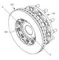
도 1은 본 발명의 실시 예에 따른 인벌류트 스퍼마운팅 디스크를 도시한 사시도이다.
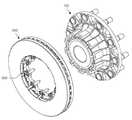
도 2는 도 1에 도시된 제동디스크의 디스크부와 허브부를 분해하여 도시한 분해사시도이다.
도 3은 도 1에 도시된 허브부와 베어링 하우징을 분해하여 도시한 분해사시도이다.
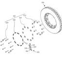
도 4는 도 1에 도시된 디스크부에서 체결부를 분해하여 도시한 분해사시도이다.
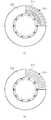
도 5의 (a)는 디스크부의 사시도이고, (b)는 (a)를 평면방향에서 바라본 도면이다.
도 6의 (a)는 디스크부의 일부를 절개하여 바라본 벤틸부의 베인 구조 예시도이며, 도 5의 (b)는 벤틸부의 플로이드 구조 예시도이다.
도 7의 (a)는 허브부와 디스크부를 직체결하는 종래의 제동디스크의 열 응력 해석 결과이며, (b)는 인벌류트 타입의 볼트체결홀을 형성하는 본 발명의 제동디스크의 열 응력 해석 결과이고, (c)는 응력분산홀이 더 형성된 본 발명의 제동디스크의 열 응력 해석 결과이다.
도 8은 도 1의 제동디스크의 A-A' 단면도이다.
도 9 내지 도 11은 도 1 내지 도 8에 도시된 허브부에 대한 베어링 하우징의 인서트 방법과 디스크부의 제조방법을 설명하기 위한 도면들이다.
도 12는 허브부와 디스크부를 직체결하는 종래의 제동디스크와 본 발명의 실시 예에 따른 인벌류트 스퍼마운팅 디스크의 열크랙 성능을 비교한 실험 결과이다.
도 13의 (a)는 허브부와 디스크부를 직체결하는 종래의 제동디스크의 진동과 소음 발생 실험 과정을 예시한 도면이며, (b)는 도 13의 (a)의 실험에 따른 결과그래프이다.
도 14의 (a)는 본 발명의 실시 예에 따른 인벌류트 스퍼마운팅 디스크의 진동과 소음 발생 실험 과정을 예시한 도면이며, (b)는 도 14의 (a)의 실험에 따른 결과그래프이다.1 is a perspective view showing an involute spur mounting disk according to an embodiment of the present invention.
FIG. 2 is an exploded perspective view showing a disk portion and a hub portion of the braking disk shown in FIG. 1.
3 is an exploded perspective view showing the hub portion and the bearing housing shown in FIG. 1 in an exploded manner.
4 is an exploded perspective view showing a fastening part in the disk part shown in FIG. 1 by exploding.
5A is a perspective view of a disk portion, and FIG. 5B is a view viewed from a planar direction of (a).
FIG. 6A is an exemplary view of a vane structure of a ventil portion viewed by cutting a portion of the disk portion, and FIG. 5B is an exemplary view of a flowid structure of the ventil portion.
7A is a thermal stress analysis result of a conventional braking disk in which the hub portion and the disk portion are directly connected, and (b) is the thermal stress analysis result of the braking disk of the present invention forming an involute type bolt fastening hole. And (c) is the thermal stress analysis result of the braking disk of the present invention in which the stress distribution hole is further formed.
8 is a cross-sectional view taken along AA′ of the braking disk of FIG. 1.
9 to 11 are diagrams for explaining a method of inserting a bearing housing and a method of manufacturing a disk portion for the hub portion shown in FIGS. 1 to 8.
12 is an experiment result of comparing the thermal crack performance of a conventional braking disk in which a hub portion and a disk portion are directly connected to an involute spur mounting disk according to an embodiment of the present invention.
FIG. 13A is a diagram illustrating a vibration and noise generation experiment process of a conventional braking disk in which a hub part and a disk part are directly connected, and (b) is a result graph according to the experiment of FIG. 13A.
14(a) is a diagram illustrating a vibration and noise generation experiment process of an involute spur mounting disk according to an embodiment of the present invention, and (b) is a graph of the results according to the experiment of FIG. 14(a).
이하, 도면을 참조한 본 발명의 설명은 특정한 실시 형태에 대해 한정되지 않으며, 다양한 변환을 가할 수 있고 여러 가지 실시예를 가질 수 있다. 또한, 이하에서 설명하는 내용은 본 발명의 사상 및 기술 범위에 포함되는 모든 변환, 균등물 내지 대체물을 포함하는 것으로 이해되어야 한다.Hereinafter, the description of the present invention with reference to the drawings is not limited to a specific embodiment, and various transformations may be applied and various embodiments may be provided. In addition, the content described below should be understood to include all conversions, equivalents, and substitutes included in the spirit and scope of the present invention.
이하의 설명에서 제1, 제2 등의 용어는 다양한 구성요소들을 설명하는데 사용되는 용어로서, 그 자체에 의미가 한정되지 아니하며, 하나의 구성요소를 다른 구성요소로부터 구별하는 목적으로만 사용된다.In the following description, terms such as first and second are terms used to describe various elements, and their meanings are not limited thereto, and are used only for the purpose of distinguishing one element from other elements.
본 명세서 전체에 걸쳐 사용되는 동일한 참조번호는 동일한 구성요소를 나타낸다.The same reference numbers used throughout this specification denote the same elements.
본 발명에서 사용되는 단수의 표현은 문맥상 명백하게 다르게 뜻하지 않는 한, 복수의 표현을 포함한다. 또한, 이하에서 기재되는 "포함하다", "구비하다" 또는 "가지다" 등의 용어는 명세서상에 기재된 특징, 숫자, 단계, 동작, 구성요소, 부품 또는 이들을 조합한 것이 존재함을 지정하려는 것으로 해석되어야 하며, 하나 또는 그 이상의 다른 특징들이나, 숫자, 단계, 동작, 구성요소, 부품 또는 이들을 조합한 것들의 존재 또는 부가 가능성을 미리 배제하지 않는 것으로 이해되어야 한다.Singular expressions used in the present invention include plural expressions unless the context clearly indicates otherwise. In addition, terms such as "include", "include" or "have" described below are intended to designate the presence of features, numbers, steps, actions, components, parts, or combinations thereof described in the specification. It is to be construed and not to preclude the possibility of addition or presence of one or more other features, numbers, steps, actions, components, parts, or combinations thereof.
다르게 정의되지 않는 한, 기술적이거나 과학적인 용어를 포함해서 여기서 사용되는 모든 용어들은 본 발명이 속하는 기술 분야에서 통상의 지식을 가진 자에 의해 일반적으로 이해되는 것과 동일한 의미를 갖고 있다. 일반적으로 사용되는 사전에 정의되어 있는 것과 같은 용어들은 관련 기술의 문맥 상 갖는 의미와 일치하는 의미를 갖는 것으로 해석되어야 하며, 본 출원에서 명백하게 정의하지 않는 한, 이상적이거나 과도하게 형식적인 의미로 해석되지 않는다.Unless otherwise defined, all terms used herein, including technical or scientific terms, have the same meaning as commonly understood by one of ordinary skill in the art to which the present invention belongs. Terms as defined in a commonly used dictionary should be interpreted as having a meaning consistent with the meaning in the context of the related technology, and should not be interpreted as an ideal or excessively formal meaning unless explicitly defined in this application. Does not.
또한, 첨부 도면을 참조하여 설명함에 있어, 도면 부호에 관계없이 동일한 구성 요소는 동일한 참조부호를 부여하고 이에 대한 중복되는 설명은 생략하기로 한다. 본 발명을 설명함에 있어서 관련된 공지 기술에 대한 구체적인 설명이 본 발명의 요지를 불필요하게 흐릴 수 있다고 판단되는 경우 그 상세한 설명을 생략한다.In addition, in the description with reference to the accompanying drawings, the same reference numerals are assigned to the same components regardless of the reference numerals, and redundant descriptions thereof will be omitted. In describing the present invention, when it is determined that a detailed description of related known technologies may unnecessarily obscure the subject matter of the present invention, a detailed description thereof will be omitted.
이하에서 본 발명의 실시 예에 따른 인벌류트 스퍼마운팅 디스크에 관하여 첨부된 도면을 기초로 상세하게 설명하면서 구체적인 실시 예를 함께 살펴본다.Hereinafter, an involute spur mounting disk according to an embodiment of the present invention will be described in detail based on the accompanying drawings, and a specific embodiment will be described together.
도 1은 본 발명의 실시 예에 따른 인벌류트 스퍼마운팅 디스크를 도시한 사시도이며, 도 2는 도 1에 도시된 제동디스크의 디스크부와 허브부를 분해하여 도시한 분해사시도이고, 도 3은 도 1에 도시된 허브부와 베어링 하우징을 분해하여 도시한 분해사시도이다.1 is a perspective view showing an involute spur mounting disk according to an embodiment of the present invention, FIG. 2 is an exploded perspective view showing a disk portion and a hub portion of the braking disk shown in FIG. 1, and FIG. 3 is FIG. It is an exploded perspective view showing by disassembling the hub portion and the bearing housing shown in FIG.
또한, 도 4는 도 1에 도시된 디스크부에서 체결부를 분해하여 도시한 분해사시도이며, 도 5의 (a)는 디스크부의 사시도이고, (b)는 (a)를 평면방향에서 바라본 도면이며, 도 6의 (a)는 디스크부의 일부를 절개하여 바라본 벤틸부의 베인 구조 예시도이고, 도 5의 (b)는 벤틸부의 플로이드 구조 예시도이다.In addition, FIG. 4 is an exploded perspective view showing an exploded fastening part in the disk part shown in FIG. 1, FIG. 5(a) is a perspective view of the disk part, and (b) is a view viewed from a planar direction, FIG. 6A is an exemplary view of a vane structure of a ventil portion viewed by cutting a portion of the disk portion, and FIG. 5B is an exemplary view of a flowid structure of the ventil portion.
도 7의 (a)는 허브부와 디스크부를 직체결하는 종래의 제동디스크의 열 응력 해석 결과이며, (b)는 인벌류트 타입의 볼트체결홀을 형성하는 본 발명의 제동디스크의 열 응력 해석 결과이고, (c)는 응력분산홀이 더 형성된 본 발명의 제동디스크의 열 응력 해석 결과이며, 도 8은 도 1의 제동디스크의 A-A' 단면도이다.7A is a thermal stress analysis result of a conventional braking disk in which the hub portion and the disk portion are directly connected, and (b) is the thermal stress analysis result of the braking disk of the present invention forming an involute type bolt fastening hole. And (c) is a result of thermal stress analysis of the brake disk of the present invention in which the stress distribution hole is further formed, and FIG. 8 is a cross-sectional view taken along AA′ of the brake disk of FIG. 1.
도 1 내지 도 7을 참조하면, 본 발명의 실시 예에 따른 인벌류트 스퍼마운팅 디스크는, 허브부(100), 디스크부(200) 및 체결부(300)를 포함하여 구성될 수 있다.1 to 7, an involute spur mounting disk according to an embodiment of the present invention may include a
구체적으로, 허브부(100)는 내부가 중공되어 외주면과 내주면을 이루며, 일단에는 플랜지부(110)가 마련될 수 있다. 플랜지부(110)는 차량의 휠 등과 결합하기 위한 스터드 볼트(117)가 체결되는 공간으로, 원주 방향을 따라 스터드 볼트(117)가 체결될 복수의 볼트체결공(115)이 일정간격으로 형성될 수 있다.Specifically, the
또한, 허브부(100)는 내주면에 베어링 하우징(150)이 장착될 수 있다. 베어링 하우징(150)은 차축(미도시)이 삽입될 수 있으며, 차축(미도시)은 베어링 하우징(150)과 함께 구비되는 베어링(미도시)에 맞물려 회전이 원활할 수 있다.In addition, the
여기서, 베어링 하우징(150)은 허브부(100)와 따로 각각 제작되어 허브부(100)에 조립될 수도 있으나, 바람직하게는 허브부(100)의 제작 시 허브부(100)의 내부로 인서트되며, 세레이션부(600)를 통한 허브부(100)와의 결속 등을 통해 허브부(100)로부터 이탈되지 않는 구조를 형성할 수 있다. 이에 대한 자세한 설명은 도 9 내지 도 11을 참조하여 후술하기로 한다.Here, the bearing
또한, 허브부(100)는 외주면 둘레를 따라 복수의 볼트삽입홀(125)이 일정 간격으로 형성될 수 있다. 이를 위해, 허브부(100)는 외주면에 복수의 돌출면(120)을 마련할 수 있으며, 볼트삽입홀(125)은 상기 복수의 돌출면(120)에 마련될 수 있다. In addition, the
이때, 복수의 돌출면(120)과 볼트삽입홀(125)은 스터드 볼트(117)와의 간섭을 피하기 위해 플랜지부(110)의 볼트체결공(115)과는 평행이 되지 않도록 서로 교차하는 위치에 형성될 수 있다. 다만, 복수의 돌출면(120)과 볼트삽입홀(125)은 플랜지부(110) 상에 형성되지 않고 플랜지부(110)의 타측에서 허브부(100)의 외주면 상을 따라 형성될 수 있다. 즉, 복수의 돌출면(120)과 볼트삽입홀(125)은 볼트체결공(115)과는 허브부(100)의 서로 다른 원주상에서 교차되는 위치로 마련되는 것이다.At this time, the plurality of protruding
디스크부(200)는 복수의 돌출면(120)을 통해 허브부(100)에 안착될 수 있고, 후술하는 체결부(300)에 의해 허브부(100)에 고정될 수 있다. 여기서, 허브부(100)의 내주면에는 디스크부(200)의 내주면과 같거나 작은 외경의 안착가이드면(130)이 디스크부(200) 장착 방향으로 돌출되어 디스크부(200)의 장착이 원활하도록 안내할 수도 있다.The
또한, 안착가이드면(130)에는 복수의 통기공(135) 원주상을 따라 마련될 수 있으며, 이를 통해 무게를 절감하며 열 배출 효과를 높일 수도 있다.In addition, the
이러한 허브부(100)는 알루미늄 재질로 마련될 수 있으며, 바람직하게는 인장강도와 냉각성능에 유리한 A356 재질로 마련될 수 있으나, 반드시 이에 한정되는 것은 아니며 작업자의 의도에 따라서 다양한 재질로서 마련될 수 있다.The
허브부(100)에 대한 고정을 위해, 디스크부(200)는 내주면을 따라 볼트삽입홀(125)과 상응하는 인벌류트(involute)형의 볼트체결홀(215)이 형성될 수 있다. 여기서, 인벌류트(involute)란 원통에 감아붙인 실을 헐거워지지 않도록 당기면서 풀 때, 그 실 끝이 그리는 곡선을 지칭하는 것으로, 기어의 치형 곡선이 주로 이 인벌류트를 바탕으로 제작된다.For fixing to the
본 발명은 이러한 치형 곡선의 주를 이루는 인벌류트 타입으로 볼트체결홀(215)을 형성하였는데, 인벌류트 타입의 볼트체결홀(215)은 디스크부(200)가 열 변형에 원심 반대 방향으로 자유 팽창성을 갖도록 하는 동시에 응력 집중 분산 효과가 높은 장점이 있으며, 특히 이러한 효과는 후술하는 디스크부(200)의 벤틸레이티드 구조와 응력분산홀(217)의 마련에 따라 더욱 극대화 될 수 있다.In the present invention, the
보다 구체적으로, 디스크부(200)는 브레이크 캘리퍼(미도시)가 장착되어 압착하며 차량 휠의 회전을 정지시킬 수 있는 부재로, 제1 디스크(210), 제2 디스크(220) 및 벤틸부(230)를 포함하여 구성될 수 있다.More specifically, the
여기서, 제1 디스크(210)는 허브부(100)와 직접 맞닿아 체결되는 디스크로서, 상기의 볼트체결홀(215)이 형성될 수 있으며, 제2 디스크(220)는 벤틸부(230)를 사이에 두고 제1 디스크(210)와 대향 배치될 수 있다.Here, the
즉, 디스크부(200)는 제1 디스크(210), 벤틸부(230), 제2 디스크(220)가 순차적으로 형성되는 구조이며, 디스크부(200)의 허브부(100) 체결 시 제1 디스크(210)는 허브부(100)와 가장 가깝고 제2 디스크(220)는 허브부(100)에서 가장 먼 형태일 수 있다.That is, the
이러한 제1 디스크(210)와 제2 디스크(220)는 허브부(100)와의 결합과 열 방출 등을 위해 각각 중공되도록 형성될 수 있고, 동일한 내/외주면을 갖는 동일한 형태로 마련될 수도 있다.The
그러나, 반드시 한정되는 것은 아니며 후술하는 리브(240)의 형성과 열 배출을 향상시키는 등의 목적에 따라 제2 디스크(220)의 내주면 직경이 제1 디스크(210)의 내주면 직경보다 크도록 형성될 수도 있다.However, it is not necessarily limited, and the inner circumferential diameter of the
즉, 제2 디스크(220)의 내주면 직경이 제1 디스크(210)의 내주면 직경보다 클 경우, 허브부(100)와 맞닿는 제1 디스크(210)로부터 제2 디스크(220)부에 이르기까지 내주면이 확장되는 구조일 수 있다.That is, when the diameter of the inner circumferential surface of the
벤틸부(230)는 상술한 바와 같이 제1 디스크(210)와 제2 디스크(220) 사이에 마련될 수 있으며, 도 6의 (a)와 같이 베인 구조로 형성되거나, 도 6의 (b)와 같이 플로이드 형태로 형성될 수 있다. 이외에도, 벤틸부(230)는 공기를 배출할 수 있는 다양한 구조를 모두 포함할 수 있다.The
상기와 같이 구성되는 디스크부(200)는 허브부(100)나 베어링 하우징(150)에서 발생되는 마찰열, 그리고 브레이크 캘리퍼의 제동 시 발생되는 마찰열 등을 각 디스크(210, 220)의 중공부와 벤틸부(230) 등을 통해 외부로 신속하고 원활하게 배출할 수가 있다.The
한편, 제1 디스크(210), 제2 디스크(220) 및 벤틸부(230)를 포함하여 구성되는 디스크부(200)는 차압주조방식 등을 통해 제작 시 상기의 구성들이 모두 일체화될 수 있는데, 이에 대한 자세한 설명은 허브부(100)와 베어링 하우징(150)의 인서트 방식을 설명할 때 함께 설명하기로 한다.On the other hand, the
볼트체결홀(215)은 상술한 바와 같이 제1 디스크(210)에 형성될 수 있으며, 제1 디스크(210)와 제2 디스크(220)의 내주면이 같게 형성되는 경우에 따라서 제2 디스크(220)에도 선택적으로 마련될 수 있다.The
여기서, 볼트체결홀(215)은 양측으로 마련되는 직선부(215a)와 상기 양측 직선부(215a)를 연결하는 곡선부(215b)를 포함하여 구성될 수 있으며, 이러한 볼트체결홀(215)와 상술한 허브부(100)의 볼트삽입홀(125)을 통해 체결부(300)를 삽입 장착함으로써 허브부(100)와 디스크부(200)는 체결될 수가 있다.Here, the
여기서, 볼트체결홀(215)의 곡선부(215b)는 체결부(300)가 장착되는 공간일 수 있으며, 직선부(215a)는 디스크부(200)의 열 팽창 시 디스크부(200)가 일정 범위를 벗어나지 않고 복귀가 수월하도록 가이드하는 부분일 수 있다. 그러나, 이는 예시적인 것으로 한정되지는 않으며, 체결부(300)는 직선부(215a)에 장착될 수도 있다.Here, the
이와 같은 구조로 형성되는 본 발명의 실시 예에 따른 인벌류트 스퍼마운팅 디스크는, 체결부(300)에 의해 허브부(100)와 디스크부(200)의 결속은 유지하되 원심 반대방향으로는 구속하는 구성이 없기 때문에, 제동 시 발생되는 디스크부(200)의 열 팽창과 방열 후 수축이 자유롭게 형성될 수 있고, 이로 인해 허브부(100)와 디스크부(200)를 직체결하는 구조 대비 뒤틀림이 현저하게 감소되고, 결국 내구성이 향상되는 효과를 나타낼 수 있다.The involute spur mounting disk according to an embodiment of the present invention formed in such a structure maintains the binding between the
또한, 본 발명은 볼트체결홀(215)이 디스크부(200)의 원주상을 따라 일정 간격으로 균형배치 형성되고, 열 팽창 시 가이드하는 직선부(215a)를 포함하여 구성되는 인벌류트 타입이기 때문에 응력 집중을 도 7의 (b)에 도시된 바와 같이 균형적이게 분산시킬 수 있고, 디스크부(200)의 열팽창에 대한 자유성을 형성하면서도 원위치로 돌아오는 복귀성도 뛰어날 수 있다.In addition, in the present invention, since the
한편, 디스크부(200)는 제1 디스크(210)의 내주면과 제2 디스크(220)의 내주면을 연결하는 리브(240)가 더 형성될 수도 있다.Meanwhile, the
여기서, 리브(240)는 볼트체결홀(215)과 상응하는 위치마다 형성될 수 있으며, 제2 디스크(220)의 내주면 직경이 제1 디스크(210)의 내주면 직경보다 클 경우에는 경사지게 형성될 수도 있다.Here, the
이러한 리브(240)는 디스크부(200)의 강성을 보강하면서도 그 면을 따라 공기의 흐름을 발생시켜 허브부(100), 체결부(300) 또는 디스크부(200)에서 발생되는 열을 외부 방향으로 유도할 수가 있다.These
또한, 디스크부(200)는 볼트체결홀(215)이 형성되는 디스크에 응력분산홀(217)을 마련하여 응력 분산 효과를 극대화 할 수도 있다.In addition, the
구체적으로, 응력분산홀(217)은 제1 디스크(210)에 형성될 수 있고, 제2 디스크(220)에는 볼트체결홀(215)의 마련 여부에 따라 선택적으로 형성될 수 있다.Specifically, the
제1 디스크(210)에 형성되는 응력분산홀(217)은 볼트체결홀(215)에 집중되는 응력을 분산시키기 위해 마련되는 것으로서, 열 응력의 균형적인 분산을 위해 볼트체결홀(215) 사이마다 형성될 수 있고, 볼트체결홀(215)의 깊이(BD)와는 동일하고 직선부(215a) 폭(W)보다는 큰 직경 길이(D)를 형성할 수가 있다.The stress distribution holes 217 formed in the
여기서, 바람직하게는 볼트체결홀(215)의 직선부(215a) 폭(W) 대비 응력분산홀(217)의 직경 길이(D)는 1:2의 비율일 수 있으나, 반드시 한정되는 것은 아니다.Here, preferably, the diameter length D of the
이러한 응력분산홀(217)은 도 7의 (a) 내지 (c)에 도시된 바와 같이 종래 대비하여는 열 응력을 약 1/3으로 분산시킬 수 있으며, 볼트체결홀(215)만 마련되는 경우에 대비하여는 열 응력을 약 60%로 분산시킬 수 있다.Such a
아울러, 상기와 같이 구성되는 디스크부(200)는 강성이 있고 열 발생 시 허브부(100)로 열을 전도하는 회주철 또는 구상흑연주철의 재질로 마련될 수 있으며, 바람직하게는 FC210D로 형성될 수 있으나, 이는 예시적인 것으로 한정되는 것은 아니며 디스크부(200)는 브레이크 캘리퍼의 작동에도 강하게 견디며 열 발생 시 허브부(100)로 열 전도를 빠르게 시킬 수 있는 이종 재질이면 충분하다.In addition, the
디스크부(200)는 구상흑연주철 등으로 형성되어 열 전도성이 비교적 큰 AL356 재질 등으로 형성되는 다른 재질의 허브부(100)를 통해 열을 빠르게 전도하면서, 벤틸부(230) 등을 통한 열 배출을 통해 보다 현저한 냉각성능을 나타낼 수가 있다.The
한편, 본 발명의 실시 예에 따른 인벌류트 스퍼마운팅 디스크는, 상술한 원심 반대 방향으로의 자유 팽창 구성 외에도 축방향 열 팽창과 마운팅 등도 자유롭게 형성될 수 있다.On the other hand, the involute spur mounting disk according to an embodiment of the present invention may be freely expanded in an axial direction and mounted in an axial direction in addition to the free expansion configuration in a direction opposite to the centrifugal direction described above.
이를 위해, 체결부(300)는 체결부싱(310), 스토퍼(320), 스프링 플레이트(330) 및 고정볼트(340)를 포함하여 구성될 수 있다.To this end, the
구체적으로, 체결부싱(310)은 중공된 원통형의 몸체를 형성하며, 볼트체결홀(215)을 관통하여 단부가 볼트삽입홀(125)로 삽입될 수 있다. 여기서, 체결부싱(310)은 디스크부(200)의 체결면 즉, 제2 디스크(220)의 상면보다 높게 돌출될 수 있는데, 이는 축 방향 팽창에 대한 팽창 범위를 조절하고자 함이다.Specifically, the
바람직하게는 디스크부(200)의 체결면 대비 체결부싱(310)의 돌출 높이는 약 0.5mm일 수 있으나, 이는 예시적인 것으로 반드시 한정되는 것은 아니다. 체결부싱(310)의 돌출 높이는 달리 조절될 수 있고, 높이의 조정에 따라 디스크부(200)의 축 방향 팽창 범위가 달리 형성될 수 있다.Preferably, the protruding height of the
스토퍼(320)는 체결부싱(310) 상단에 안착되도록 형성될 수 있다. 즉, 체결부싱(310)의 높이 상단에 스토퍼(320)를 구비함으로써 디스크부(200)의 팽창 범위는 체결부싱(310)의 디스크부(200)에 대한 돌출 높이로 조정될 수가 있다.The
또한, 스토퍼(320)는 디스크부(200)와 스프링 플레이트(330) 간의 유격을 형성하여 스프링 플레이트(330)가 축방향으로의 자유변형도를 갖도록 작용될 수 있다.In addition, the
스프링 플레이트(330)는 스토퍼(320) 상단에서 중심부(332)가 스토퍼(320)에 안착되어 밀착되며, 양단부가 디스크부(200)의 체결면 즉, 제2 디스크(220)의 상면과 접촉되도록 형성될 수가 있다.The
여기서, 스프링 플레이트(330)는 스토퍼(320)에 의해 디스크부(200)와 유격을 형성한 상태로 양단이 디스크부(200)에 접촉되도록 경사지도록 형성되는데, 경사진 양단을 통해 탄성력이 제공되어 축방향으로 열과 탄성 자유변형을 할 수 있는 것이다.Here, the
이를 위해, 스프링 플레이트(330)는 일 예로써 중심부(332)가 판상으로 형성되며, 양단부(334)가 'v' 자형으로 형성될 수 있으나, 반드시 한정되는 것은 아니며, 양단부(334)가 축방향으로 탄성력을 제공할 수 있는 구조면 충분하다.To this end, the
또한, 스프링 플레이트(330)는 SK5 등의 탄소공구강 재질로서 프레스 가공으로 제조될 수 있으나, 재질과 가공방법은 한정되는 것은 아니며 달리 형성될 수 있다.In addition, the
아울러, 스프링 플레이트(330)는 중심부(332)에서 사방으로 절개되는 절개부(336)를 형성하여 고정볼트(340)의 삽입이 용이하도록 형성될 수도 있다.In addition, the
고정볼트(340)는 스프링 플레이트(330), 스토퍼(320) 및 체결부싱(310)을 차례로 관통하여 볼트삽입홀(125)에 체결될 수 있다. 즉, 고정볼트(340)는 체결부싱(310)과 함께 스토퍼(320) 및 스프링 플레이트(330)를 고정시키면서 허브부(100)와 디스크부(200)의 체결을 완료할 수 있다.The fixing
이때, 허브부(100)와 디스크부(200)는 체결부싱(310) 및 고정볼트(340)에 의한 이중 체결 구조를 통해 제동 시 발생되는 회전토크에도 강한 체결력을 발휘할 수 있다.At this time, the
아울러, 체결부싱(310)과 고정볼트(340)는 SCM435 등의 무게가 가볍고 경도가 강한 소재로 형성될 수 있으며, 스토퍼(320)는 SK5 등의 탄소공구강 재질로서 형성될 수도 있으나, 이들은 모두 예시적인 것으로 한정되는 것은 아니다.In addition, the
이하, 도 9 내지 도 11을 참조하여 허브부(100)와 베어링 하우징(150)의 일체화, 그리고 디스크부(200)의 제조방식에 대해 설명하기로 한다.Hereinafter, the integration of the
도 9 내지 도 11은 도 1 내지 도 8에 도시된 허브부에 대한 베어링 하우징의 인서트 방법과 디스크부의 제조방법을 설명하기 위한 도면들이다.9 to 11 are diagrams for explaining a method of inserting a bearing housing and a method of manufacturing a disk portion for the hub portion shown in FIGS. 1 to 8.
도 9 내지 도 11을 참조하면, 허브부(100)와 베어링 하우징(150)은 각각 제작되어 허브부(100)에 조립될 수도 있으나, 바람직하게는 허브부(100)의 제작 시 허브부(100)의 내부로 인서트되어 이탈이 방지되는 구조를 형성할 수 있다.9 to 11, the
구체적으로, 허브부(100)는 베어링 하우징(150)이 사형 주조 등의 방식을 통해, 제조되고, 허브 금형에 삽입한 이후, 차압 주조 방식을 통해 일체형으로 형성될 수 있다.Specifically, the
차압 주조 방식을 이용하는 차압 주조 장치는 상부에 금형부 챔버(500)가 설치되고, 그 하부에 보온로(400)가 설치될 수 있는데, 보온로(400)에는 주조시 사용될 재료가 용융되는 용탕이 적재되거나 생성될 수 있다.In the differential pressure casting apparatus using the differential pressure casting method, a
차압 주조 장치는 금형부 챔버(500)와 보온로(400) 사이의 압력차에 의해 보온로(400)에 용융된 재료가 금형부 챔버(500)에 공급되어 주조하도록 형성될 수 있다.The differential pressure casting apparatus may be formed such that a material melted in the
도 9에 도시된 차압 주조 장치에 미리 제조된 베어링 하우징(150)을 허브 금형이 구비된 금형부 챔버(500)에 고정할 수 있고, 이어서 차압 주조 장치의 금형부 챔버(500)와 보온로(400)가 동일한 압력을 갖도록 가압할 수 있다. 이때, 금형부 챔버(500)와 보온로의 내부 압력은 동일한 압력이 유지되도록 할 수 있다.The bearing
이어서, 도 10에 도시된 바와 같이 금형부 챔버(500)의 압력을 상승시킬 수 있다. 이에 따라, 금형부 챔버와 보온로(400) 사이의 압력차에 의해 보온로(400)에 용융된 용탕이 금형부 챔버(500)로 공급될 수 있다.Subsequently, as shown in FIG. 10, the pressure of the
상기와 같이, 금형부 챔버(500)에 압력이 높아져 용융된 용탕이 금형부 챔버(500)의 금형 내에 유입되면 일반 주조 방식과 대비하여 기포발생이 현저하게 줄어든다. 또한, 물성 편차가 적어, 허브부(100)가 균일한 물성을 가질 수 있다.As described above, when the pressure in the
이후, 도 11에 도시된 바와 같이, 금형부 챔버(500) 내에 용탕인 AL356 등이 완전히 응고된 이후 금형부 챔버(500)를 분리하여 허브부(100)를 취출하면 허브부(100)와 베어링 하우징(150)은 일체화가 될 수 있다.Thereafter, as shown in FIG. 11, after the molten metal AL356 in the
이때, 허브부(100)와 베어링 하우징(150)은 각각 볼록돌기(610)와 오목홈(620)이 교차로 형성되는 세레이션부(600)를 형성하여 서로 맞물릴 수 있다. 이로 인해, 원주상 회전과 축방향 이탈이 방지될 수 있다.At this time, the
또한, 세레이션부(600)는 복수로 형성될 수도 있으며, 바람직하게는 베어링 하우징(150)은 상단과 하단이 단차를 형성하고, 세레이션부(600)는 베어링 하우징(150)의 상단과 하단부에 모두 형성될 수 있다.In addition, the
아울러, 베어링 하우징(150)은 FCD500 등의 구상흑연주철로 마련될 수 있으며, 이는 디스크부(200)가 허브부(100)로 열을 전도하는 원리로서 동일하게 베어링 하우징(150)의 열 배출도 용이할 수 있다.In addition, the bearing
한편, 허브부(100)와 베어링 하우징(150)의 일체 구조는 차압 주조 방식이 아닌 다른 방식으로 제조될 수도 있다. 예를 들면, 용탕 단조 방식을 이용할 수 있다. 그러나, 이들의 방식은 한정되는 것은 아니며 다른 주조 방식도 이용이 가능하다.Meanwhile, the integral structure of the
디스크부(200)도 상기 도 9 내지 도 11에 도시된 방법을 이용하여 제조될 수 있다.The
즉, 도 9에 도시된 바와 같이 차압 주조 장치에 미리 제조되어 결합된 제1 및 제2 디스크(220)를 금형부 챔버(500)에 고정할 수 있다. 이어서, 차압 주조 장치의 금형부 챔버(500)와 보온로(400)가 동일한 압력을 가지도록 가압한다. 이때, 금형부 챔버(500)와 보온로(400)의 내부 압력은 동일하도록 유지될 수 있다.That is, as shown in FIG. 9, the first and
이어서, 도 10에 도시된 바와 같이 금형부 챔버(500)의 압력을 상승시켜 금형부 챔버(500)와 보온로(400) 사이에 압력차를 형성시키고, 이러한 압력차에 의해 보온로(400)에 용융된 용탕이 금형부 챔버(500)로 공급되도록 한다. 이때, 용융된 용탕은 금형부 챔버(500)에 제1 및 제2 디스크(220) 사이로 공급될 수 있다.Subsequently, as shown in FIG. 10, a pressure difference is formed between the
상기와 같이, 금형부 챔버(500)에 압력이 높아져 용융된 용탕이 금형부 챔버(500)의 금형 내로 유입되면 일반 주조 방식과 대비하여 기포발생이 현저하게 줄어들고, 물상 편차가 적을 수 있다.As described above, when the pressure in the
디스크부(200)가 균일한 물성을 가짐에 따라, 브레이크 동작 또는 차축 회전 시 발생되는 열이 디스크부(200) 전체에 균일하게 전달될 수 있다.As the
이후, 도 11에 도시된 바와 같이 금형부 챔버(500) 내에 용탕이 완전히 응고된 이후 금형부 챔버(500)를 분리하여 일체형 디스크부(200)를 완성할 수 있다.Thereafter, as shown in FIG. 11, after the molten metal is completely solidified in the
아울러, 디스크부(200)는 차압 주조 방식 외에도 사형 주조 방식 등을 이용할 수도 있으며, 이는 당업자에게 있어서 흔히 알려진 주조법이므로 이하 상세한 설명은 생략하기로 한다.In addition, the
상기와 같은 체결부(300)를 포함하여 구성되는 본 발명의 실시 예에 따른 인벌류트 스퍼마운팅 디스크는, 인벌류트 타입의 볼트체결홀(215)과 응력분산홀(217)을 형성하여 열 분산도가 높고, 체결부(300)에 의한 강한 체결력을 유지하면서 제동 시에 발생되는 열 변형 즉, 원심 반대 방향으로의 열 팽창이 자유로운 팽창과 스퍼마운팅 구조를 형성하여 도 12에 도시된 바와 같이 열 크랙 방지 성능이 향상될 수 있으며, 복귀력이 우수할 수 있다.The involute spur mounting disk according to an embodiment of the present invention including the
또한, 스프링 플레이트(330)에 의해 제동 시 열변형으로 인한 축방향으로의 디스크 팽창 및 비틀림에 의해 발생되는 변형에도 구속상태를 유지하면서 마운팅 구조를 형성할 수 있고, 냉각 후에는 탄성력에 의해 원위치로 복귀될 수 있다.In addition, the
또한, 체결부싱(310)의 돌출 높이 조정 등을 통한 열 변형량을 조절할 수 있으며, 열 크랙 방지 성능을 환경에 따라 조절할 수가 있다.In addition, it is possible to adjust the amount of heat deformation by adjusting the protrusion height of the
또한, 베어링 하우징(150)과 디스크부(200)의 열 발생 시 열전도성이 높은 이종 재질로서 형성되는 허브부(100)를 통해 열 배출이 보다 빠를 수 있고, 특히 디스크부(200)는 벤틸부(230)와 함께 공기의 흐름을 발생시킴으로써 열 방출이 신속하여 냉각성능이 현저히 향상될 수 있다.In addition, when heat is generated between the bearing
또한, 베어링 하우징(150)이 허브부(100) 내부로 인서팅 주조 되어 일체화되되, 그 결속은 하나 이상의 세레이션 결합을 통해 강한 결속을 유지할 수가 있다.In addition, the bearing
아울러, 도 13에 도시된 바와 같이 허브부와 디스크부를 직체결하는 종래의 제동디스크 대비 도 14에 도시된 바와 같이 진동과 소음의 감쇄가 저감되는 효과를 지닌다.In addition, as shown in FIG. 13, compared to the conventional braking disk in which the hub part and the disk part are directly connected, as shown in FIG. 14, vibration and noise attenuation are reduced.
이상에서 첨부된 도면을 참조하여 본 발명의 실시예를 설명하였으나, 본 발명이 속하는 기술분야에서 통상의 지식을 가진 자에 의하여 다른 구체적인 형태로 실시할 수 있다는 것을 이해할 수 있을 것이다. 따라서 이상에서 기술한 실시예는 모든 면에서 예시적인 것이며 한정적이 아닌 것이다.Although the embodiments of the present invention have been described above with reference to the accompanying drawings, it will be appreciated that the present invention can be implemented in other specific forms by those of ordinary skill in the art. Therefore, the embodiments described above are illustrative and non-limiting in all respects.
100 : 허브부
110 : 플랜지부
115 : 볼트체결공
117 : 스터드 볼트
120 : 돌출면
125 : 볼트삽입홀
130 : 안착가이드면
135 : 통기공
150 : 베어링 하우징
200 : 디스크부
210 : 제1 디스크
215 : 볼트체결홀
215a : 직선부
215b : 곡선부
217 : 응력분산홀
220 : 제2 디스크
230 : 벤틸부
240 : 리브
300 : 체결부
310 : 체결부싱
320 : 스토퍼
330 : 스프링 플레이트
332 : 중심부
334 : 양단부
336 : 절개부
340 : 고정볼트
400 : 보온로
500 : 금형부 챔버
600 : 세레이션부
610 : 볼록돌기
620 : 오목홈100: hub
110: flange portion
115: bolt tightening work
117: stud bolt
120: protruding surface
125: bolt insertion hole
130: seating guide surface
135: ventilation hole
150: bearing housing
200: disk unit
210: first disk
215: bolt fastening hole
215a: straight portion
215b: curved part
217: stress distribution hole
220: second disk
230: Ventil part
240: rib
300: fastening part
310: fastening bushing
320: stopper
330: spring plate
332: center
334: both ends
336: incision
340: fixing bolt
400: heating furnace
500: mold part chamber
600: serration part
610: convex projection
620: concave groove
Claims (7)
Translated fromKorean내주면을 따라 상기 볼트삽입홀과 상응하는 인벌류트(involute)형의 볼트체결홀이 형성되는 디스크부 및
상기 볼트체결홀과 볼트삽입홀을 통해 장착되어 허브부와 디스크부를 체결하는 체결부를 포함하며,
상기 디스크부는,
상기 인벌류트형의 볼트체결홀에 의해 열 변형시 원심 반대 방향으로의 자유 팽창성을 갖고,
상기 체결부는,
상기 볼트체결홀을 관통하여 단부가 볼트삽입홀로 삽입되는 체결부싱;
상기 체결부싱 상단에 안착되도록 형성되는 스토퍼;
상기 스토퍼 상단에서 중심부가 상기 스토퍼에 밀착되며 양단부가 디스크부의 체결면과 탄성력을 갖도록 접촉되어 축방향으로 자유변형되는 스프링 플레이트 및
상기 스프링 플레이트, 스토퍼 및 체결부싱을 차례로 관통하여 볼트삽입홀에 체결되는 고정볼트를 포함하는 인벌류트 스퍼마운팅 디스크.
A bearing housing into which an axle is inserted is mounted on an inner circumferential surface, and a hub portion having a plurality of bolt insertion holes formed along the circumference at a predetermined interval on the outer circumferential surface;
A disk portion having an involute-type bolt fastening hole corresponding to the bolt insertion hole along the inner circumferential surface, and
It is mounted through the bolt fastening hole and the bolt insertion hole and includes a fastening part for fastening the hub part and the disk part,
The disk unit,
It has free expansion in the direction opposite to the centrifugal when thermally deformed by the involute type bolt fastening hole,
The fastening part,
A fastening bushing through the bolt fastening hole and having an end inserted into the bolt insertion hole;
A stopper formed to be seated on an upper end of the fastening bushing;
A spring plate whose center is in close contact with the stopper at the top of the stopper and that both ends are in contact with the fastening surface of the disk unit so as to have elastic force, and are freely deformed in the axial direction, and
An involute spur mounting disk comprising a fixing bolt that sequentially passes through the spring plate, a stopper, and a fastening bushing and is fastened to a bolt insertion hole.
상기 디스크부는,
상기 볼트체결홀이 형성되는 제1 디스크와, 베인 또는 플로이드 형태의 벤틸부를 사이에 두고 상기 제1 디스크와 대향 배치되는 제2 디스크가 일체로 형성되는 구조인 것을 특징으로 하는 인벌류트 스퍼마운팅 디스크.
The method of claim 1,
The disk unit,
The involute spur mounting disk, characterized in that the first disk in which the bolt fastening hole is formed and a second disk disposed opposite to the first disk with a vane or floyd-shaped ventil portion therebetween are integrally formed.
상기 디스크부는,
제2 디스크가 제1 디스크보다 내주면 직경이 크게 형성되고,
상기 볼트체결홀과 상응하는 위치로 제1 디스크의 내주면과 제2 디스크의 내주면을 연결하는 리브가 더 형성되는 것을 특징으로 하는 인벌류트 스퍼마운팅 디스크.
The method of claim 2,
The disk unit,
When the second disk is inner circumference than the first disk, the diameter is formed larger,
An involute spur mounting disk, characterized in that a rib connecting the inner circumferential surface of the first disk and the inner circumferential surface of the second disk is further formed at a position corresponding to the bolt fastening hole.
상기 제1 디스크는,
상기 볼트체결홀 사이마다, 볼트체결홀의 깊이(BD)와는 동일하고 직선부 폭(W)보다는 큰 직경 길이(D)를 형성하는 응력분산홀이 마련되는 것을 특징으로 하는 인벌류트 스퍼마운팅 디스크.
The method of claim 2,
The first disk,
An involute spur mounting disk, characterized in that a stress distribution hole is provided between the bolt fastening holes and forming a diameter length (D) equal to the depth (BD) of the bolt fastening hole and larger than the width (W) of the straight portion.
상기 베어링 하우징은,
차압주조방식에 의해 상기 허브부의 내주면에 인서트되되, 상기 허브부의 내주면에는 세레이션부를 형성하여 상기 인서트된 베어링 하우징의 이탈을 방지하는 것을 특징으로 하는 인벌류트 스퍼마운팅 디스크.
The method of claim 1,
The bearing housing,
The involute spur mounting disk, characterized in that it is inserted into the inner circumferential surface of the hub part by a differential pressure casting method, and a serration part is formed on the inner circumferential surface of the hub part to prevent separation of the inserted bearing housing.
상기 체결부싱은,
상기 디스크부의 체결면보다 돌출되는 높이를 형성하는 것을 특징으로 하는 인벌류트 스퍼마운팅 디스크.
The method of claim 1,
The fastening bushing,
Involute spur mounting disk, characterized in that to form a height protruding from the fastening surface of the disk portion.
Priority Applications (1)
| Application Number | Priority Date | Filing Date | Title |
|---|---|---|---|
| KR1020200043031AKR102150231B1 (en) | 2020-04-08 | 2020-04-08 | Brake disk of involute spur mounting structure |
Applications Claiming Priority (1)
| Application Number | Priority Date | Filing Date | Title |
|---|---|---|---|
| KR1020200043031AKR102150231B1 (en) | 2020-04-08 | 2020-04-08 | Brake disk of involute spur mounting structure |
Publications (1)
| Publication Number | Publication Date |
|---|---|
| KR102150231B1true KR102150231B1 (en) | 2020-08-31 |
Family
ID=72234238
Family Applications (1)
| Application Number | Title | Priority Date | Filing Date |
|---|---|---|---|
| KR1020200043031AActiveKR102150231B1 (en) | 2020-04-08 | 2020-04-08 | Brake disk of involute spur mounting structure |
Country Status (1)
| Country | Link |
|---|---|
| KR (1) | KR102150231B1 (en) |
Cited By (3)
| Publication number | Priority date | Publication date | Assignee | Title |
|---|---|---|---|---|
| KR102338288B1 (en)* | 2020-12-21 | 2021-12-14 | 주식회사 일진글로벌 | Wheel bearing having improved sensor tarket and sensor target mounting portion |
| WO2023075322A1 (en)* | 2021-10-29 | 2023-05-04 | 주식회사 세명테크 | Floating disc assembly for vehicle |
| CN116336110A (en)* | 2022-12-30 | 2023-06-27 | 山东隆基机械股份有限公司 | Niobium-containing copper alloy ball-milling cast iron brake disc |
Citations (3)
| Publication number | Priority date | Publication date | Assignee | Title |
|---|---|---|---|---|
| JP2009287621A (en)* | 2008-05-28 | 2009-12-10 | Hitachi Chem Co Ltd | Disc rotor for disc brake |
| KR20180105808A (en)* | 2017-03-16 | 2018-10-01 | 주식회사 세명테크 | High reliability and Lightweight Pre-Mounting Brake System for Commercial Vehicles |
| KR102066070B1 (en)* | 2019-07-23 | 2020-01-14 | 주식회사 세명테크 | Brake disk of spur mounting structure |
- 2020
- 2020-04-08KRKR1020200043031Apatent/KR102150231B1/enactiveActive
Patent Citations (3)
| Publication number | Priority date | Publication date | Assignee | Title |
|---|---|---|---|---|
| JP2009287621A (en)* | 2008-05-28 | 2009-12-10 | Hitachi Chem Co Ltd | Disc rotor for disc brake |
| KR20180105808A (en)* | 2017-03-16 | 2018-10-01 | 주식회사 세명테크 | High reliability and Lightweight Pre-Mounting Brake System for Commercial Vehicles |
| KR102066070B1 (en)* | 2019-07-23 | 2020-01-14 | 주식회사 세명테크 | Brake disk of spur mounting structure |
Cited By (3)
| Publication number | Priority date | Publication date | Assignee | Title |
|---|---|---|---|---|
| KR102338288B1 (en)* | 2020-12-21 | 2021-12-14 | 주식회사 일진글로벌 | Wheel bearing having improved sensor tarket and sensor target mounting portion |
| WO2023075322A1 (en)* | 2021-10-29 | 2023-05-04 | 주식회사 세명테크 | Floating disc assembly for vehicle |
| CN116336110A (en)* | 2022-12-30 | 2023-06-27 | 山东隆基机械股份有限公司 | Niobium-containing copper alloy ball-milling cast iron brake disc |
Similar Documents
| Publication | Publication Date | Title |
|---|---|---|
| KR102150231B1 (en) | Brake disk of involute spur mounting structure | |
| JP4668844B2 (en) | Opposite piston type disc brake | |
| US11346415B2 (en) | Brake disc for a vehicle | |
| JP4884363B2 (en) | Brake rotor mounting assembly that properly promotes uniform torque transmission distribution | |
| US6357561B2 (en) | Thermal expansion bushing in a metal matrix composite rotor | |
| US10781876B2 (en) | Brake disk for vehicles | |
| US9303705B2 (en) | Brake disc and mounting arrangement for a brake disc | |
| US20130213747A1 (en) | Caliper body of a disc brake | |
| US20100116603A1 (en) | Rotor Device and Method of Making Same | |
| KR20140052616A (en) | Brake disk for vehicle | |
| KR102392738B1 (en) | Vehicle Floating Disc Hub Assembly | |
| JP2005121174A (en) | Opposed piston type disk brake | |
| JP6794451B2 (en) | Brake rotor for vehicles | |
| US20090294228A1 (en) | Disc rotor for disc brake | |
| KR102066070B1 (en) | Brake disk of spur mounting structure | |
| JP2009513909A (en) | Parking brake | |
| JP4453595B2 (en) | Brake disc for railway vehicles | |
| JP7269063B2 (en) | brake disc | |
| KR102634241B1 (en) | Floating Disc Assembly for Vehicles | |
| JP4163672B2 (en) | Brake drum | |
| JP2020159543A (en) | brake disc | |
| KR102687107B1 (en) | Brake Disc Assembly | |
| KR20240178472A (en) | Disc brake | |
| JP2006038025A (en) | Disc rotor mounting structure and disc brake device | |
| JP2009115172A (en) | Disc brake |
Legal Events
| Date | Code | Title | Description |
|---|---|---|---|
| PA0109 | Patent application | St.27 status event code:A-0-1-A10-A12-nap-PA0109 | |
| PA0201 | Request for examination | St.27 status event code:A-1-2-D10-D11-exm-PA0201 | |
| P11-X000 | Amendment of application requested | St.27 status event code:A-2-2-P10-P11-nap-X000 | |
| P13-X000 | Application amended | St.27 status event code:A-2-2-P10-P13-nap-X000 | |
| PA0302 | Request for accelerated examination | St.27 status event code:A-1-2-D10-D17-exm-PA0302 St.27 status event code:A-1-2-D10-D16-exm-PA0302 | |
| D13-X000 | Search requested | St.27 status event code:A-1-2-D10-D13-srh-X000 | |
| D14-X000 | Search report completed | St.27 status event code:A-1-2-D10-D14-srh-X000 | |
| PE0902 | Notice of grounds for rejection | St.27 status event code:A-1-2-D10-D21-exm-PE0902 | |
| E13-X000 | Pre-grant limitation requested | St.27 status event code:A-2-3-E10-E13-lim-X000 | |
| P11-X000 | Amendment of application requested | St.27 status event code:A-2-2-P10-P11-nap-X000 | |
| P13-X000 | Application amended | St.27 status event code:A-2-2-P10-P13-nap-X000 | |
| P11-X000 | Amendment of application requested | St.27 status event code:A-2-2-P10-P11-nap-X000 | |
| P13-X000 | Application amended | St.27 status event code:A-2-2-P10-P13-nap-X000 | |
| E701 | Decision to grant or registration of patent right | ||
| PE0701 | Decision of registration | St.27 status event code:A-1-2-D10-D22-exm-PE0701 | |
| P11-X000 | Amendment of application requested | St.27 status event code:A-2-2-P10-P11-nap-X000 | |
| P13-X000 | Application amended | St.27 status event code:A-2-2-P10-P13-nap-X000 | |
| R15-X000 | Change to inventor requested | St.27 status event code:A-3-3-R10-R15-oth-X000 | |
| R16-X000 | Change to inventor recorded | St.27 status event code:A-3-3-R10-R16-oth-X000 | |
| GRNT | Written decision to grant | ||
| PR0701 | Registration of establishment | St.27 status event code:A-2-4-F10-F11-exm-PR0701 | |
| PR1002 | Payment of registration fee | St.27 status event code:A-2-2-U10-U11-oth-PR1002 Fee payment year number:1 | |
| PG1601 | Publication of registration | St.27 status event code:A-4-4-Q10-Q13-nap-PG1601 | |
| R18-X000 | Changes to party contact information recorded | St.27 status event code:A-5-5-R10-R18-oth-X000 | |
| R18-X000 | Changes to party contact information recorded | St.27 status event code:A-5-5-R10-R18-oth-X000 | |
| R18-X000 | Changes to party contact information recorded | St.27 status event code:A-5-5-R10-R18-oth-X000 | |
| PR1001 | Payment of annual fee | St.27 status event code:A-4-4-U10-U11-oth-PR1001 Fee payment year number:4 | |
| R18-X000 | Changes to party contact information recorded | St.27 status event code:A-5-5-R10-R18-oth-X000 | |
| PR1001 | Payment of annual fee | St.27 status event code:A-4-4-U10-U11-oth-PR1001 Fee payment year number:5 | |
| PR1001 | Payment of annual fee | St.27 status event code:A-4-4-U10-U11-oth-PR1001 Fee payment year number:6 |