KR102148858B1 - Guide-wire handler for measuring blood-vessel pressure using optical pressure sensor - Google Patents
Guide-wire handler for measuring blood-vessel pressure using optical pressure sensorDownload PDFInfo
- Publication number
- KR102148858B1 KR102148858B1KR1020180159243AKR20180159243AKR102148858B1KR 102148858 B1KR102148858 B1KR 102148858B1KR 1020180159243 AKR1020180159243 AKR 1020180159243AKR 20180159243 AKR20180159243 AKR 20180159243AKR 102148858 B1KR102148858 B1KR 102148858B1
- Authority
- KR
- South Korea
- Prior art keywords
- connector
- switch
- guide wire
- cap
- case
- Prior art date
- Legal status (The legal status is an assumption and is not a legal conclusion. Google has not performed a legal analysis and makes no representation as to the accuracy of the status listed.)
- Active
Links
Images


Classifications
- A—HUMAN NECESSITIES
- A61—MEDICAL OR VETERINARY SCIENCE; HYGIENE
- A61B—DIAGNOSIS; SURGERY; IDENTIFICATION
- A61B5/00—Measuring for diagnostic purposes; Identification of persons
- A61B5/02—Detecting, measuring or recording for evaluating the cardiovascular system, e.g. pulse, heart rate, blood pressure or blood flow
- A61B5/021—Measuring pressure in heart or blood vessels
- A61B5/0215—Measuring pressure in heart or blood vessels by means inserted into the body
- A—HUMAN NECESSITIES
- A61—MEDICAL OR VETERINARY SCIENCE; HYGIENE
- A61B—DIAGNOSIS; SURGERY; IDENTIFICATION
- A61B2562/00—Details of sensors; Constructional details of sensor housings or probes; Accessories for sensors
- A61B2562/02—Details of sensors specially adapted for in-vivo measurements
- A61B2562/0247—Pressure sensors
Landscapes
- Health & Medical Sciences (AREA)
- Life Sciences & Earth Sciences (AREA)
- Cardiology (AREA)
- Engineering & Computer Science (AREA)
- Heart & Thoracic Surgery (AREA)
- Physiology (AREA)
- Biophysics (AREA)
- Pathology (AREA)
- Vascular Medicine (AREA)
- Biomedical Technology (AREA)
- Physics & Mathematics (AREA)
- Medical Informatics (AREA)
- Molecular Biology (AREA)
- Surgery (AREA)
- Animal Behavior & Ethology (AREA)
- General Health & Medical Sciences (AREA)
- Public Health (AREA)
- Veterinary Medicine (AREA)
- Measuring Pulse, Heart Rate, Blood Pressure Or Blood Flow (AREA)
Abstract
Translated fromKoreanDescription
Translated fromKorean본 발명은 혈관 협착증 부위를 찾기 위하여 혈관 압력을 측정할 수 있는 광압력센서가 부착된 가이드 와이어를 다루기 위한 핸들러에 관한 것이다.The present invention relates to a handler for handling a guide wire attached with an optical pressure sensor capable of measuring blood vessel pressure in order to find a vascular stenosis site.
일반적으로 관상동맥 혈관 협착증 부위를 찾는 방법으로는 조형제를 이용하는 방법이 있다. 즉 혈관에 조형제를 투입하고, X-lay영상판독을 통하여 협착부위를 판별하고 있다. 그러나 조형제를 통한 혈관 협착부위 판별은 의사의 판단에 좌우되어 정확한 협착 부위를 찾기 어렵다는 점이 지적되고 있다.In general, as a method of finding the site of coronary artery stenosis, there is a method using a molding agent. In other words, a formative agent is injected into the blood vessel, and the stricture area is determined through X-lay image reading. However, it has been pointed out that it is difficult to find the exact stricture area because the determination of the vascular stricture area through the molding agent depends on the judgment of the doctor.
반면 압력센서를 이용하는 방법의 경우, 혈관 내 협착부위의 압력을 측정하고, 측정된 압력을 기준압력(PA)과 비교함으로써 압력 변화치를 정확한 수치로 확인 가능하여 혈관 내 협착위치를 정확히 판별할 수 있다.On the other hand, in the case of using a pressure sensor, it is possible to accurately determine the stricture position in the blood vessel by measuring the pressure at the stricture area in the blood vessel and comparing the measured pressure with the reference pressure (PA). .
대한민국 공개특허 제10-2018-0020978호에는 혈관 내 측정을 위한 장치 및 방법에 대하여 개시되어 있다. 개시된 선행특허를 살펴보면, 모니터링 가이드 와이어가 포터블 디스플레이 유닛의 커넥터에 결합되며, 모니터링 가이드 와이어가 혈관 속으로 들어가면 모니터링 가이드 와이어의 센서로부터의 신호가 포터블 디스플레이 유닛에 전달되어 혈관 내 압력 등 혈관 상태가 측정될 수 있다.Korean Patent Application Publication No. 10-2018-0020978 discloses an apparatus and method for intravascular measurement. Looking at the disclosed prior patent, the monitoring guide wire is coupled to the connector of the portable display unit, and when the monitoring guide wire enters the blood vessel, a signal from the sensor of the monitoring guide wire is transmitted to the portable display unit to measure blood vessel conditions such as intravascular pressure. Can be.
이에 선행특허를 포함하여 압력센서를 이용하는 종래기술의 경우, 구조적 접속 손실을 최소화하여 센서에서 감지되는 신호를 노이즈(noise)없이 정확히 전달하며, 가이드 와이어를 복잡한 혈관을 따라 유연하게 이동시키는 방안에 대한 연구가 시급히 요구되고 있다.Therefore, in the case of the prior art using a pressure sensor including the prior patent, a method of minimizing structural connection loss to accurately transmit the signal detected by the sensor without noise, and to flexibly move the guide wire along the complex blood vessel. Research is urgently required.
본 발명은 상기한 문제점을 해결하기 위하여 안출된 것으로서, 가이드 와이어와 광접속단자의 구조적 접속 손실을 최소화할 수 있고, 아울러 광접속단자에 대하여 가이드 와이어를 자유 회전시킬 수 있는 광압력센서를 이용하는 혈관 압력 측정용 가이드 와이어 핸들러를 제공하는 데 목적이 있다.The present invention was devised to solve the above problems, and it is possible to minimize the structural connection loss between the guide wire and the optical connection terminal, and at the same time, a blood vessel using an optical pressure sensor capable of freely rotating the guide wire with respect to the optical connection terminal. It is an object to provide a guide wire handler for pressure measurement.
상기한 과제를 실현하기 위한 본 발명에 따른 광압력센서를 이용하는 혈관 압력 측정용 가이드 와이어 핸들러는, 선단을 통해 광접속단자가 삽입되고, 말단을 통해 광압력센서가 장착된 가이드 와이어가 삽입되어 상기 광접속단자와 접속되며, 일측에 스위치 홀이 형성된 케이스와; 상기 케이스의 내부에 회전 가능토록 설치되며, 내부에 상기 가이드 와이어가 관입되고, 말단에 상기 케이스의 말단을 통해 돌출된 부분의 외측면에 캡 결합부가 구비되며, 상기 케이스의 스위치 홀에 대응되는 외측면 일측에 스위치 결속부가 구비된 커넥터와; 상기 가이드 와이어가 관입되며, 선단 측이 상기 커넥터의 말단을 통해 상기 커넥터에 삽입되고, 말단에 탄력적으로 오므려져 상기 가이드 와이어를 결속할 수 있는 집게부가 구비되는 그리퍼와; 상기 커넥터의 캡 결합부에 착탈 가능토록 결합되며, 상기 가이드 와이어가 관입되며, 내부에 상기 그리퍼의 집게부가 삽입되어 오므려지는 결속부가 형성되는 캡과; 상기 커넥터 및 이에 결속된 그리퍼와 캡의 자유 회전을 제한할 수 있도록 상기 케이스의 스위치 홀 측에 설치되어 상기 커넥터의 스위치 결속부와 결속되는 스위치를 포함한다.In the guide wire handler for measuring blood vessel pressure using an optical pressure sensor according to the present invention for realizing the above object, an optical connection terminal is inserted through a tip, and a guide wire equipped with an optical pressure sensor is inserted through the end. A case connected to the optical connection terminal and having a switch hole formed on one side thereof; It is installed to be rotatable inside the case, the guide wire is penetrated therein, a cap coupling part is provided on the outer surface of the portion protruding through the end of the case at the end, and the outer corresponding to the switch hole of the case A connector provided with a switch binding portion on one side thereof; A gripper through which the guide wire is penetrated, a tip side is inserted into the connector through an end of the connector, and is elastically closed at an end thereof and provided with a tong portion capable of binding the guide wire; A cap that is detachably coupled to the cap coupling portion of the connector, through which the guide wire is penetrated, and a coupling portion formed therein by inserting a clamp portion of the gripper to be closed; And a switch installed at the switch hole side of the case so as to limit free rotation of the connector, the gripper coupled thereto, and the cap, and coupled to the switch binding portion of the connector.
상기 커넥터의 스위치 결속부는 링기어 형태이며, 상기 스위치의 내측면에는 상기 스위치의 누름 조작에 의해 상기 링기어의 치와 치 사이 틈새 중 어느 하나에 끼워질 수 있는 걸림턱이 형성될 수 있다.The switch coupling portion of the connector has a ring gear shape, and a locking protrusion capable of being fitted into any one of a tooth and a gap between the teeth of the ring gear may be formed on an inner surface of the switch by pressing the switch.
상기 스위치의 내측면에는 상기 스위치의 누름 조작에 의해 상기 케이스의 내부를 향하는 쐐기가 돌출 형성되며, 상기 커넥터는 상기 스위치의 쐐기에 의해 말단 측으로 직선 이동될 수 있도록 상기 스위치의 쐐기가 밀접되는 경사부를 갖고, 상기 커넥터와 케이스 사이에는 상기 스위치의 누름 조작 해제시 상기 스위치 쐐기에 의해 직선 이동된 커넥터를 복귀할 수 있도록 탄성력을 부여하는 탄성부재가 개재될 수 있다.On the inner side of the switch, a wedge toward the inside of the case is protruded by a pressing operation of the switch, and the connector is a slope portion to which the wedge of the switch is in close contact so that the wedge of the switch can be linearly moved toward the distal end In addition, an elastic member may be interposed between the connector and the case to provide an elastic force so as to return the connector linearly moved by the switch wedge when the switch is pressed and released.
상기 광접속단자의 말단에는 상기 가이드 와이어 측과 접속되는 접속핀이 돌출 형성되며, 상기 접속핀에는 상기 가이드 와이어와의 접속을 연결하는 슬리브가 선택적으로 착탈 가능토록 결합될 수 있다.A connection pin connected to the guide wire side is protruded from an end of the optical connection terminal, and a sleeve connecting the connection with the guide wire may be selectively attached to and detached from the connection pin.
본 발명에 따른 광압력센서를 이용하는 혈관 압력 측정용 가이드 와이어 핸들러는 가이드 와이어를 자유롭게 회전시킬 수 있기 때문에 복잡한 혈관을 따라 유연하게 이동시킬 수 있고, 가이드 와이어를 그리퍼로 결속시킨 상태에서 커넥터, 슬리브 등을 통해 광접속단자와 구조적으로 접속시키기 때문에 접속 손실을 최소화하여 센서에서 감지되는 신호를 노이즈(noise)없이 정확히 전달할 수 있다.The guide wire handler for blood vessel pressure measurement using the optical pressure sensor according to the present invention can flexibly move along a complex blood vessel because the guide wire can be freely rotated, and connectors, sleeves, etc., while the guide wire is bound by a gripper. Since it is structurally connected to the optical connection terminal through the connection, the signal detected by the sensor can be accurately transmitted without noise by minimizing connection loss.
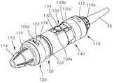
도 1은 본 발명의 일 실시예에 따른 광압력센서를 이용하는 혈관 압력 측정용 가이드 와이어 핸들러에 관한 사시도이고,
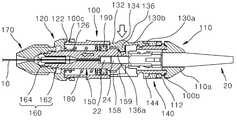
도 2는 도 1에 도시된 핸들러의 분해 사시도이고,
도 3은 도 1에 도시된 핸들러의 분해상태 부분 단면도이고,
도 4는 도 1에 도시된 핸들러의 단면도로서, 스위치 누름 해제상태 단면도이고,
도 5는 도 1에 도시된 핸들러의 단면로서, 스위치 누름상태 단면도이고,
도 6은 본 발명에 따른 핸들러에 의해 접속되는 압력표시장치와 가이드 와이어의 블록도이다.1 is a perspective view of a guide wire handler for measuring blood vessel pressure using an optical pressure sensor according to an embodiment of the present invention,
2 is an exploded perspective view of the handler shown in FIG. 1,
3 is a partial cross-sectional view of the handler shown in FIG. 1 in an exploded state;
Figure 4 is a cross-sectional view of the handler shown in Figure 1, a cross-sectional view of a switch depressed state,
Figure 5 is a cross-sectional view of the handler shown in Figure 1, a cross-sectional view of a switch pressed state,
6 is a block diagram of a pressure display device and a guide wire connected by a handler according to the present invention.
첨부된 도면을 참조하여 본 발명의 바람직한 실시 예를 설명하면 다음과 같다.A preferred embodiment of the present invention will be described with reference to the accompanying drawings.
도 1 내지 도 6에 도시된 바와 같이, 본 발명에 따른 광압력센서(40)를 이용하는 혈관 압력 측정용 가이드 와이어 핸들러는, 가이드 와이어(10)와 압력표시장치(30) 측의 광접속단자(20)를 구조적으로 접속시키는 것으로, 케이스(100,110,120)와, 스위치(130,140)와, 커넥터(150)와, 그리퍼(160)와, 캡(170)을 포함한다.1 to 6, a guide wire handler for measuring blood vessel pressure using the
가이드 와이어(10)는 혈관을 따라 이동 가능토록 가늘고 길게 형성된다. 가이드 와이어(10)는 내부에 광섬유를 수용할 수 있는 중공구조를 갖으며 말단에는 혈관내에서의 진입효율을 높일 수 있게 나선형으로 연장방향을 따라 감긴 나선 스프링구조의 진입선단부가 마련될 수 있다. 가이드 와이어(10)는 금속소재로 형성될 수 있다.The
가이드 와이어(10)의 내부에는 광섬유(12)가 관입된다. 가이드 와이어(10)의 선단은 광접속단자(20)와 구조적으로 접속된다. 가이드 와이어(10)의 말단에는 광섬유(12)와 접속되어 혈관 내 압력을 측정할 수 있는 광압력센서(40)가 내장된다.An
광압력센서(40)는 광섬유(12)의 말단과 일정 거리를 두고 이격되게 설치된 가요성 격막(42)이 혈관 내 압력(F)에 의해 변형될 수 있게 형성되어 있다. 이러한 광압력센서(40)는 가요성 격막(42)의 변형 정도에 따라 광섬유(12)의 말단과 가유성 격막(42) 사이 거리가 변하고, 광섬유(12)의 말단과 가요성 격막(42) 사이 거리 변화에 대응하여 광검출기(34)에서 검출되는 피크 파장이 이동된다. 이러한 광검출기(34)로부터 검출되는 피크 파장의 이동을 산출부(36)에서 압력으로 산출하고, 표시부(38)를 통해 표시한다.The
광접속단자(20)의 말단에는 가이드 와이어(10)가 접속되는 접속핀(22)이 구성된다. 광접속단자(20)의 접속핀(22)에는 접속 길이, 관경 차이를 해소할 수 있는 슬리브(24)가 선택적으로 결합될 수 있다. 광접속단자(20)의 슬리브(24)는 접속핀(22)에 착탈 가능토록 끼움 결합될 수 있다. 예컨대 도시된 바와 같이 광접속단자(20)의 슬리브(24)는 광접속단자(20)의 접속핀(22)보다 길게 형성되고, 관직경이 변하는 다단 구조로 이루어질 수 있다. 광접속단자(20)의 접속핀(22)과 슬리브(24)는 가이드 와이어(10)가 삽입 가능토록 중공 구조로 이루어질 수 있다.A
광접속단자(20)의 선단에는 가이드와이어(10)의 광섬유(12)를 통해 전송되는 신호를 전송하는 광섬유(미도시)가 내장되어 슬리브(24)에 접속된 페룰에 말단이 결합되어 있다.An optical fiber (not shown) for transmitting a signal transmitted through the
압력표시장치(30)는 광접속단자(20)를 통해 광섬유(12)로 빛을 공급하는 광원(32)과, 광압력센서(40)로부터 서큘레이터를 통해 전달되는 광신호를 수신하여 전기적 신호로 출력하는 광검출기(34)와, 광검출기(34)에서 수신된 신호로부터 혈관 내 압력을 산출하는 산출부(36)와, 산출된 혈관 내 압력을 육안으로 볼 수 있도록 표시하는 모니터 등의 표시부(38) 등으로 구성될 수 있다.The
케이스(100,110,120)는 핸들러의 외관을 구성하며 선단을 통해 광접속단자(20)가 삽입되고 말단을 통해 가이드 와이어(10)의 선단이 삽입되는 것으로, 본체(100)와, 선단덮개(110)와, 말단덮개(120)를 포함할 수 있다.The case (100, 110, 120) constitutes the exterior of the handler, and the
본체(100)는 선단 및 말단이 모두 개방되며 내부가 빈 원통 구조로 형성될 수 있다. 본체(100)는 외경이 변하는 다단 구조로 형성될 수 있다. 즉 본체(100)는 선단이 상대적으로 외경이 작은 소경부(102)로 이루어지고, 말단이 상대적으로 외경이 더 큰 대경부(104)로 이루어질 수 있다.The
본체(100)의 내부에는 본체(100)의 대경부(104)와 소경부(102)를 구획하는 격벽(106)이 구성될 수 있다. 격벽(106)의 중앙에는 광접속단자(20)의 접속핀(22) 또는 슬리브(24)가 관통될 수 있도록 관통홀(106a)이 형성될 수 있다.A
본체(100)의 외측면 일측에는 스위치(130,140)가 설치되는 스위치 홀(100a)이 형성될 수 있다. 스위치 홀(100a)은 본체(100)의 대경부(104)와 소경부(102) 경계를 중심으로 본체(100)의 대경부(104) 및 소경부(102) 측으로 각각 일정 길이 형성될 수 있다. 스위치 홀(100a)은 본체(100)의 원둘레방향을 따라 복수개 형성될 수 있다. 즉 스위치 홀(100a)은 서로 대향되는 위치에 형성된 한 쌍으로 이루어질 수 있다. 아울러 본체(100)의 소경부(102) 외측면에는 스위치 홀(100a)의 양 옆 가장자리를 둘러막는 담벽(108)이 돌출 형성될 수 있다.A
본체(100)의 외측면 선단에는 선단덮개(110)와 착탈 가능토록 결합될 수 있도록 선단덮개 결합부가 구성될 수 있다. 선단덮개 결합부는 본체(100)의 반경 외측방향으로 돌출된 돌기(100b)로 이루어질 수 있다. 선단덮개 결합부용 돌기(100b)는 서로 대향되게 위치되는 한 쌍으로 이루어질 수 있다. 선단덮개 결합부용 돌기(100b)는 본체(100)의 원둘레방향을 따라 스위치 홀(100a)과 같은 회전각방향 위치에 각각 형성될 수 있다.The front end of the outer surface of the
본체(100)의 외측면 말단에는 말단덮개(120)와 착탈 가능토록 결합될 수 있도록 말단덮개 결합부가 구성될 수 있다. 말단덮개 결합부는 본체(100)의 반경 외측방향으로 돌출된 돌기(100c)로 이루어질 수 있다. 말단덮개 결합부용 돌기(100c)는 서로 대향되게 위치되는 한 쌍으로 이루어질 수 있다. 말단덮개 결합부용 돌기(100c)는 본체(100)의 원둘레방향을 따라 스위치 홀(100a)과 같은 회전각방향 위치에 각각 형성될 수 있다.The end of the outer surface of the
선단덮개(110)는 본체(100)의 선단 외측에 끼워질 수 있도록 일측 밑면이 개방된 캡(cap) 구조로 형성될 수 있다. 선단덮개(110)의 타측 밑면은 본체(100)의 선단을 덮을 수 있도록 개방되지 않되, 광접속단자(20)가 관통될 수 있도록 중앙에 관통홀(110a)이 형성될 수 있다. 선단덮개(110)의 관통홀(110a)은 광접속단자(20)의 말단부가 걸려 이탈되지 않도록 크기, 형상 등이 결정될 수 있다.The
선단덮개(110)의 옆면에는 본체(100)와 착탈 가능토록 결합될 수 있도록 결합부가 구성될 수 있다. 선단덮개(110)의 결합부는 상술한 본체(100)의 선단덮개 결합부용 돌기(100b)가 끼워질 수 있는 결합홀(112)로 형성될 수 있다. 선단덮개(110)의 결합홀(112)은 본체(100)의 선단덮개 결합부용 돌기(100b)가 원둘레를 따라 일정 거리 이동 가능토록 길게 형성될 수 있다. 선단덮개(110)의 결합홀(112) 또한 서로 대향되는 위치에 형성되는 한 쌍으로 이루어질 수 있다. 아울러 선단덮개(110)의 옆면에는 본체(100)의 선단덮개 결합부용 돌기(100b)를 선단덮개(110)의 결합홀(112)로 안내할 수 있도록 가이드 통로(미도시)가 형성될 수 있다. 선단덮개(110)의 가이드 통로는 선단덮개(110)의 결합홀(112)의 일측 끝단에서부터 선단덮개(110)의 말단까지 일자형으로 형성될 수 있다. 선단덮개(110)의 가이드 통로 또한 한 쌍의 이루어질 수 있다.The side surface of the
말단덮개(120) 또한 선단덮개(110)와 동일, 유사한 구조로 형성될 수 있다. 즉 말단덮개(120)는 일측 밑면이 개방된 원통형 캡으로 형성되고, 개방되지 않은 타측 밑면에 관통홀(120a)이 형성될 수 있다. 말단덮개(120)의 옆면에는 한 쌍의 결합홀(122) 및 한 쌍의 가이드 통로(124)가 형성될 수 있다. 말단덮개(120)의 관통홀(120a)은 후술할 커넥터(150)의 대경부(152)까지 관통 가능한 크기로 형성될 수 있다.
한편 말단덮개(120)의 관통홀(120a) 측에는 말단덮개(120)의 내부를 향해 돌출되며 말단덮개(120)의 관통홀(120a)을 둘러싸는 링형 플랜지(126)가 구성될 수 있다. 말단덮개(120)의 링형 플랜지(126)에는 스프링(180)의 말단이 끼워짐으로써 스프링(180)을 지지할 수 있다.On the other hand, at the side of the through
말단덮개(120)의 개방되지 않은 밑면에는 캡(170)의 일부가 삽입될 수 있는 캡 삽입홈(120b)이 형성될 수 있다.A
스위치(130,140)는 조작 방식 등에 따라 다양하게 실시될 수 있다.The
바람직하게는 스위치(130,140)는 버튼 방식으로 구성될 수 있다. 즉 스위치(130,140)는 후술할 커넥터(150)의 스위치 결속부(158)와 기계적으로 결속될 수 있는 걸림턱(132)을 지지하는 지지부(130)와, 지지부(130)를 케이스의 본체(100)에 고정시키는 고정부(140)를 포함할 수 있다.Preferably, the
스위치의 걸림턱(132)은 스위치의 지지부(130)의 말단에 전후방향으로 일정 길이 돌출 형성될 수 있다.The locking
스위치의 지지부(130)는 본체(100)의 스위치 홀(100a)을 통해 탄력적으로 본체(100)의 내부로 눌려지고, 외력이 없어지면 복귀될 수 있도록 플라스틱과 같은 탄성력을 갖는 재질로 이루어질 수 있다. 스위치의 지지부(130)는 외팔보처럼 본체(100)에 결합될 수 있다. 즉 스위치의 지지부(130)는 일부가 본체(100)의 소경부(102)에 고정되는 고정단(130a)이고, 나머지 일부가 본체(100)의 스위치 홀(100a)에 위치되어 눌림 조작 가능한 자유단(130b)으로 이루어질 수 있다. 스위치의 지지부(130)의 고정단(130a)은 본체(100)의 담벽(108)에 걸릴 수 있도록 원둘레방향에 대하여 폭이 스위치의 지지부(130)의 자유단(130b)보다 더 넓을 수 있다. 스위치의 지지부(130)의 고정단(130a)은 스위치의 지지부(130)의 자유단(130b) 측 말단이 상대적으로 더 두껍게 형성되고, 그 선단이 상대적으로 더 얇게 형성되어, 스위치의 고정부(140)가 걸리는 단차(130c)가 구성될 수 있다.The
스위치의 고정부(140)는 케이스의 본체(100)의 소경부(102)에 끼워져 스위치의 지지부(130)의 고정단(130a) 선단을 케이스의 본체(100)에 밀착시킬 수 있는 링형 부재로 이루어질 수 있다. 스위치의 고정부(140)는 스위치의 지지부(130) 단차(130c)와 케이스의 선단덮개(110) 사이에 개재됨으로써 고정될 수 있다. 스위치의 고정부(140)는 그 내경이 대략 본체(100)의 소경부(102) 외경과 크기가 같도록 형성되어, 본체(100)의 소경부(102)에 면접될 수 있다. 이때 스위치의 고정부(140)의 내주면에는 본체(100)의 선단을 통해 본체(100)의 소경부에 끼워질 때 본체(100)의 선단덮개 결합부용 돌기(100b)가 걸리지 않고 관통될 수 있도록 관통홈(142)이 형성될 수 있다. 스위치의 고정부(140)의 내주면에는 스위치의 지지부(130)의 고정단(130a) 선단에 끼워질 수 있도록 끼움홈(144)이 형성될 수 있다. 스위치의 고정부(140)의 관통홈(142)과 끼움홈(144)은 원둘레방향을 따라 서로 다른 위치에 형성될 수 있다.The fixing
스위치의 지지부(130)의 외측면에는 조작 용이 및 편의를 위해 반구형 등의 둔턱(134)이 돌출 형성될 수 있다.A
한편 스위치의 지지부(130)의 내측면에는 본체(100)의 스위치 홀(100a)을 통해 본체(100)의 내부로 돌출되는 쐐기(136)가 구성될 수 있다. 스위치(130,140)의 쐐기(136)는 커넥터(150)의 선단 측에 대응되게 위치될 수 있으며, 이에 커넥터(150)가 보다 용이하고 원활하게 직선 이동될 수 있다. 스위치(130,140)의 쐐기(136)는 외력을 충분히 전달받을 수 있도록 스위치(130,140)의 둔턱(134) 밑에 위치될 수 있다. 스위치(130,140)의 쐐기(136)는 말단면이 본체(100)의 내부로 갈수록 좁아지는 경사면(136a)으로 형성될 수 있으며, 이에 스위치(130,140)를 누르는 힘에 의해 커넥터(150)가 용이하게 직선 이동될 수 있다.Meanwhile, a
이와 아울러 스위치(130,140)를 누르는 힘이 해제되어 스위치(130,140) 복귀시 커넥터(150) 및 그리퍼(160), 캡(170) 또한 케이스(100,110,120)의 선단쪽으로 직선 이동하여 원상 복귀될 수 있도록 탄성부재가 설치될 수 있다. 탄성부재는 다양하게 실시될 수 있다. 즉 탄성부재는 커넥터(150)의 외측에 끼워져 커넥터(150)와 케이스의 본체(100) 사이에 개재되며, 커넥터(150)의 직선 이동방향을 따라 탄성 변형되는 스프링(180)으로 이루어질 수 있다. 스프링(180)의 선단은 후술할 베어링(190)에 밀착되고, 스프링(180)의 말단은 말단덮개(120)의 링형 플랜지(126)에 끼워질 수 있다.In addition, the force pressing the
한편 스프링(180)의 선단을 지지할 수 있도록 커넥터(150)의 선단 측에는 스프링 시트(185)가 끼워질 수 있다.Meanwhile, a
커넥터(150)는 가이드 와이어(10)를 회전시킬 수 있도록 본체(100)의 대경부(104)에 자유 회전 가능토록 삽입된다.The
커넥터(150)는 선단을 통해 광접속단자(20)의 접속핀(22) 또는 슬리브(24)가 삽입되고, 말단을 통해 그리퍼(160)가 삽입되며, 가이드 와이어(10)가 관입될 수 있도록 중공의 파이프 구조로 형성될 수 있다.
커넥터(150)는 외경이 변하는 다단 구조로 형성될 수 있다. 바람직하게는 커넥터(150)는 선단에서 말단으로 갈수록 외경이 단계적으로 작아질 수 있다. 예컨대 커넥터(150)는 상대적으로 외경이 큰 대경부(152)와, 대경부(152)보다 외경이 작은 중간부(154)와, 중간부(154)보다 외경이 작은 소경부(156)로 이루어질 수 있다. 커넥터(150)의 소경부(156)와 중간부(154)는 캡(170)의 내부에 삽입 가능한 크기로 형성될 수 있다.The
커넥터(150)의 외측면 말단, 즉 커넥터(150)의 소경부(156)에는 캡(170)과 착탈 가능토록 결합될 수 있도록 캡 결합부(156a)가 구성될 수 있다. 바람직하게는 커넥터(150)와 캡(170)이 나사 체결이 가능토록 커넥터(150)의 캡 결합부(156a)는 나선부로 이루어질 수 있다.The outer end of the
커넥터(150)의 외측면에는 커넥터(150)의 캡 결합부(156a) 선단에 걸림턱(156b)이 돌출 형성될 수 있다. 커넥터(150)의 걸림턱(156b)은 링형으로 형성될 수 있다. 커넥터(150)의 걸림턱(156b)은 커넥터(150)의 소경부(156)와 중간부(154) 경계에 형성될 수 있다.On the outer surface of the
커넥터(150)의 걸림턱(156b)은 캡(170)에 구조적으로 걸리되, 어느 정도 힘을 주면 캡(170)의 내부에 삽입되거나 캡(170)으로부터 이탈 가능토록 캡(170)의 선단 내경과 대략 같은 직경으로 형성될 수 있다. The hooking
커넥터(150)의 외측에는 스위치(130,140)와 결속될 수 있는 스위치 결속부(158)가 구성된다. 스위치 결속부(158)는 케이스(100,110,120)의 스위치 홀(100a)에 대응되게 위치될 수 있도록 커넥터(150)의 대경부(152)에 구성될 수 있다. 스위치 결속부(158)는 스위치(130,140)와의 결속 방법에 따라 다양하게 실시될 수 있다. 바람직하게는 스위치 결속부(158)는 커넥터(150)의 대경부(152)보다 직경이 큰 링기어 형태로 형성될 수 있다. 즉 스위치 결속부(158)는 복수개의 치가 그 사이 사이로 스위치의 걸림턱(132)이 끼워질 수 있도록 커넥터(150)의 전둘레에 일정 틈새를 유지하며 일정하게 배열됨으로써 이루어질 수 있다. 따라서 케이스(100,110,120)에 대하여 커넥터(150)의 회전각방향/위치가 어디든 상관없이 스위치의 걸림턱(132)이 커넥터(150)의 스위치 결속부(158)에 끼워져 커넥터(150)를 결속시킬 수 있다. 커넥터(150)의 스위치 결속부(158)는 결합시 스위치(130,140)와 대향될 수 있도록 커넥터(150)의 외측 선단 측에 구성될 수 있다.Outside of the
한편 커넥터(150)는 커넥터(150)의 대경부(152)로부터 선단 측으로 연장 형상되며, 선단으로 갈수록 외경이 점진적으로 작아지는 경사부(159)를 더 포함할 수 있다. 커넥터(150)의 경사부(159)는 스위치(130,140)의 쐐기(136)의 경사면(136a)과 면접될 수 있도록 스위치(130,140)의 쐐기(136)의 경사면(136a)의 경사와 대응되게 경사진다. 이에 스위치(130,140)의 쐐기(136)가 커넥터(150)의 직선 이동방향과 수직방향으로 눌려지더라도 커넥터(150)가 용이하게 직선 이동될 수 있다.Meanwhile, the
커넥터(150)와 케이스(100,110,120) 사이에는 커넥터(150)가 케이스(100,110,120)에 대하여 자유 회전이 용이하도록 베어링(190)이 개재될 수 있다. 베어링(190)은 커넥터(150)의 대경부(152)에 끼워질 수 있다.A bearing 190 may be interposed between the
그리퍼(160)는 커넥터(150)에 결합되어 가이드 와이어(10)를 결속한다. 그리퍼(160)는 가이드 와이어(10)가 관통되는 중공관 형태로 형성될 수 있다. 그리퍼(160)는 커넥터 결합부(162)와, 집게부(164)로 구성될 수 있다. 그리퍼(160)의 커넥터 결합부(162)는 커넥터(150)의 말단을 통해 커넥터(150)의 내부에 삽입된다. 그리퍼(160)의 커넥터 결합부(162)는 커넥터(150)와 일체로 회전되거나 회전 제한될 수 있도록 커넥터(150)의 소경부(156) 내경에 대응되는 크기로 형성될 수 있다. 그리퍼(160)의 집게부(164)는 그리퍼(160)의 커넥터 결합부(162) 말단에 구성된다. 그리퍼(160)의 집게부(164)는 그리퍼(160)의 커넥터 결합부(162)보다는 더 큰 직경으로 형성된다. 그리퍼(160)의 집게부(164)는 방사상으로 배열되어 오므리거나 벌어질 수 있는 복수개의 집게발(164a)들로 구성된다. 그리퍼(160)의 집게부(164)는 전체적으로 말단으로 갈수록 점진적으로 외경이 작아지는 원뿔대 형태로 형성될 수 있다. 아울러 그리퍼(160)의 커넥터 결합부(162)의 말단에는 그리퍼(160)의 집게발과 집게발 사이 절개선의 연장선인 절개선(162a)이 형성될 수 있다.The
캡(170)은 커넥터(150)에 체결되어 그리퍼(160)의 집게발들을 오므려 그리퍼(160)의 집게발들이 가이드 와이어(10)의 일측을 잡아 가이드 와이어(10)를 결속하게 한다.The
캡(170)은 가이드 와이어(10)가 관통되며 커넥터(150) 및 그리퍼(160)의 집게부(164)가 삽입될 수 있도록 중공의 파이프 형태로 형성될 수 있다.The
캡(170)은 외형에 따라 원통부(172)와 원뿔대 형상부(174)로 구성될 수 있다. 캡(170)의 원통부(172)는 커넥터(150) 및 그리퍼(160)의 집게부(164)가 삽입되는 곳으로 외경이 일정한 원통으로 형성될 수 있다. 캡(170)의 원뿔대 형상부(174)는 말단으로 갈수록 점진적으로 외경이 작아지는 원뿔대 형상으로 형성될 수 있다. 이에 캡(170)의 말단을 통해 가이드 와이어(10)의 관입이 용이하고 편할 수 있다.The
캡(170)의 원통부(172) 내부는 캡(170)의 선단에서 말단방향으로 순서대로 살펴보면, 커넥터(150)의 중간부(154) 외경과 대응하여 커넥터(150)의 중간부(154)가 삽입되는 대경부(172a)와, 커넥터(150)의 소경부(156) 외경과 대응하며 나사 체결 가능토록 나선이 형성된 결합부(172b)와, 그리퍼(160)의 집게부(164)를 오므리는 결속부(172c)로 이루어질 수 있다. 캡(170)의 결속부(172c)는 그리퍼(160)에 관입된 가이드 와이어(10)가 결속될 수 있도록 그리퍼(160)의 집게부(164)를 완전히 오므린 형상에 대응하는 원뿔대 형상으로 형성될 수 있다. 이때 캡(170)의 결속부(172c)의 옆면 및 그리퍼(160)의 집게부(164)의 옆면이 캡(170)과 그리퍼(160)의 결합방향에 대하여 경사면이기 때문에 점진적으로 캡(170)의 결속부(172c)에 그리퍼(160)의 집게부(164)가 삽입되면서 오므려지거나 이탈되면서 벌어질 수 있다.The inside of the
한편 캡(170)의 원뿔대 형상부(174)의 내부는 말단으로 갈수록 점진적으로 직경이 커지는 원뿔대 형상일 수 있다. 이에 가이드 와이어(10)가 캡(170)에 용이하게 관입될 수 있다.Meanwhile, the inside of the truncated cone-shaped
상기와 같이 구성되는 본 발명의 일 실시예에 따른 광압력센서를 이용하는 혈관 압력 측정용 가이드 와이어 핸들러의 작용효과를 상세히 설명하면 다음과 같다.The effect of the guide wire handler for measuring blood vessel pressure using an optical pressure sensor according to an embodiment of the present invention configured as described above will be described in detail as follows.
본 발명의 핸들러의 조립과정은 다음과 같다.The assembly process of the handler of the present invention is as follows.
케이스의 본체(100)의 스위치 홀(100a)에 스위치의 지지부(130)를 위치시킨 상태에서 스위치의 고정부(140)를 케이스의 본체(100)의 선단에 끼운 다음, 스위치의 고정부(140)의 끼움홈(144)이 스위치의 지지부(130)와 일렬로 배열되도록 스위치의 고정부(140)를 일정 각도 회전시킨 후, 스위치의 고정부(140)의 끼움홈(144)에 스위치의 지지부(130)의 고정단(130a) 선단이 끼워지도록 스위치의 고정부(140)를 스위치의 지지부(130) 측으로 민다.With the
다음 광접속단자(20)의 선단을 통해 광접속단자(20)에 선단덮개(110)를 끼운 다음, 선단덮개(110)의 가이드 통로(미도시)에 본체(100)의 선단덮개 결합부용 돌기(100b)가 끼워지도록 위치시켜 선단덮개(110)를 본체(100)의 선단에 밀착시켜 선단덮개(110)의 결합홀(112)에 본체(100)의 선단덮개 결합부용 돌기(100b)를 위치시키고, 그 상태에서 선단덮개(110)를 일정 각도 회전시킨다.Next, insert the
그리고, 커넥터(150)에 베어링(190)과 스프링(180)을 차례로 끼운 다음, 케이스의 본체(100) 말단을 통해 커넥터(150)를 삽입하고, 커넥터(150)에 그리퍼(160)를 삽입한다.Then, the
다음 선단덮개(110)와 마찬가지로 말단덮개(120)를 케이스의 본체(100)의 말단에 끼운 다음, 회전시킨다.Like the next
다음 가이드 와이어(10)의 선단에 캡(170)을 끼운 상태에서, 가이드 와이어(10)를 그리퍼(160) 및 커넥터(150)에 관입시켜 광접속단자(20)의 접속핀(22) 또는 슬리브(24)에 구조적으로 접속시킬 수 있다.Next, in the state where the
다음 스위치(130,140)를 눌러 커넥터(150) 및 그리퍼(160)의 자유 회전을 구속한 상태에서, 캡(170)을 커넥터(150)의 소경부(156)에 끼워 돌리면 나사 체결에 의해 캡(170)이 커넥터(150)에 고정된다. 이와 아울러 캡(170)에 의해 그리퍼(160)의 집게부(164)가 오므려진 상태이기 때문에 그리퍼(160)의 집게부(164)에 가이드 와이어(10)가 결속되어 핸들러로부터 이탈되지 않고 고정될 수 있다.Then, in the state in which the free rotation of the
반면 상기와 반대과정을 통해 본 발명의 핸들러를 분해할 수 있다.On the other hand, the handler of the present invention can be disassembled through the process opposite to the above.
이와 같이 본 발명의 핸들러를 조립하면, 도 4에 도시된 바와 같이 스위치(130,140)를 누르지 않은 상태에서는 스위치의 걸림턱(132)과 커넥터(150)의 스위치 결속부(158)가 서로 구조적으로 이격된 상태이기 때문에 캡(170)을 잡고 돌리면 커넥터(150) 및 이에 결속된 그리퍼(160), 캡(170)이 일체로 케이스(100,110,120)에 대하여 자유 회전될 수 있으며, 이에 따라 그리퍼(160)에 결속된 가이드 와이어(10)가 회전될 수 있다.When the handler of the present invention is assembled in this way, as shown in FIG. 4, when the
반면 도 5에 도시된 바와 같이 스위치(130,140)의 둔턱(134) 부분을 누르면, 스위치(130,140)의 쐐기(136)가 커넥터(150)의 경사부(159)를 따라 케이스(100,110,120) 내부로 이동되면, 스위치(130,140)의 쐐기(136)에 밀려 커넥터(150) 및 이에 결속된 그리퍼(160)와 캡(170)이 말단 측으로 직선 이동된다. 이와 아울러 스위치의 걸림턱(132)이 커넥터(150)의 스위치 결속부(158)에 끼워짐으로써 스위치(130,140)에 커넥터(150)가 결속되어 케이스(100,110,120)에 대하여 커넥터(150) 및 이에 결속된 그리퍼(160)와 캡(170)의 상대 회전이 제한된다.On the other hand, as shown in FIG. 5, when pressing the
이에 스위치(130,140)를 계속 눌러 커넥터(150) 및 그리퍼(160), 캡(170)의 회전이 구속된 상태를 유지하면서 캡(170)을 잡고 돌리면 캡(170)과 커넥터(150)의 소경부(156)의 나사 체결이 해제됨으로써 캡(170)을 분리시킬 수 있다. 캡(170)이 분리되면, 그리퍼(160)에 의한 가이드 와이어(10)의 결속 또한 해제되어 가이드 와이어(10)를 빼내 다시 관입시키거나 교체할 수 있다.Accordingly, by continuously pressing the
한편 스위치(130,140)를 더 이상 누르지 않게 되면, 스위치의 지지부(130)가 탄성력에 의해 복귀됨에 따라 스위치(130,140)의 쐐기(136)가 더 이상 커넥터(150)의 선단을 말단 측으로 밀지 않게 되며, 이에 스프링(180)의 탄성력에 의해 커넥터(150) 및 이에 결속된 그리퍼(160), 캡(170)이 제위치로 직선 이동되어 복귀될 수 있다. 그리고 스위치의 걸림턱(132)이 커넥터(150)의 스위치 결속부(158)로부터 이탈됨으로써 다시 커넥터(150) 및 그리퍼(160), 캡(170)의 자유 회전이 가능해져 가이드 와이어(10)를 회전시킬 수 있다.On the other hand, when the
이상에서 설명된 본 발명에 따른 광압력센서를 이용하는 혈관 압력 측정용 가이드 와이어 핸들러는 가이드 와이어(10)를 혈관내로 진입시킬 때 핸들러에 대해 별도의 핸들러의 회전조작 없이도 가이드와이어(10)가 혈관과의 접촉시 진입저항이 줄어드는 방향으로 자유롭게 회전되기 때문에 진입이 원할하게 이루어지는 장점을 제공한다.In the guide wire handler for measuring blood vessel pressure using the optical pressure sensor according to the present invention described above, when the
10; 가이드 와이어 20; 광접속단자
100; 본체 110; 선단덮개
120; 말단덮개 130; 스위치 지지부
140; 스위치 고정부 150; 커넥터
160; 그리퍼 170; 캡
180; 스프링 190; 베어링10;
100;
120;
140; Switch fixing
160;
180;
Claims (4)
Translated fromKorean상기 케이스의 내부에 회전 가능토록 설치되며, 내부에 상기 가이드 와이어가 관입되고, 말단에 상기 케이스의 말단을 통해 돌출된 부분의 외측면에 캡 결합부가 구비되며, 상기 케이스의 스위치 홀에 대응되는 외측면 일측에 스위치 결속부가 구비된 커넥터와;
상기 가이드 와이어가 관입되며, 선단 측이 상기 커넥터의 말단을 통해 상기 커넥터에 삽입되고, 말단에 탄력적으로 오므려져 상기 가이드 와이어를 결속할 수 있는 집게부가 구비되는 그리퍼와;
상기 커넥터의 캡 결합부에 착탈 가능토록 결합되며, 상기 가이드 와이어가 관입되며, 내부에 상기 그리퍼의 집게부가 삽입되어 오므려지는 결속부가 형성되는 캡과;
상기 커넥터 및 이에 결속된 그리퍼와 캡의 자유 회전을 제한할 수 있도록 상기 케이스의 스위치 홀 측에 설치되어 상기 커넥터의 스위치 결속부와 결속되는 스위치를 포함하는 것을 특징으로 하는 광압력센서를 이용하는 혈관 압력 측정용 가이드 와이어 핸들러.A case in which an optical connection terminal is inserted through a tip end, a guide wire equipped with an optical pressure sensor is inserted through an end thereof, and connected to the optical connection terminal, and a switch hole is formed on one side thereof;
It is installed to be rotatable inside the case, the guide wire is penetrated therein, a cap coupling part is provided on the outer surface of the portion protruding through the end of the case at the end, and the outer corresponding to the switch hole of the case A connector provided with a switch binding portion on one side thereof;
A gripper through which the guide wire is penetrated, a tip side is inserted into the connector through an end of the connector, and is elastically closed at an end thereof and provided with a tong portion capable of binding the guide wire;
A cap that is detachably coupled to the cap coupling portion of the connector, through which the guide wire is penetrated, and a coupling portion formed therein by inserting a clamp portion of the gripper to be closed;
Blood vessel pressure using an optical pressure sensor, characterized in that it includes a switch installed at the switch hole side of the case and coupled to the switch binding portion of the connector so as to limit free rotation of the connector and the gripper and the cap bound thereto. Guide wire handler for measurement.
상기 커넥터의 스위치 결속부는 링기어 형태이며,
상기 스위치의 내측면에는 상기 스위치의 누름 조작에 의해 상기 링기어의 치와 치 사이 틈새 중 어느 하나에 끼워질 수 있는 걸림턱이 형성된 것을 특징으로 하는 광압력센서를 이용하는 혈관 압력 측정용 가이드 와이어 핸들러.The method of claim 1,
The switch binding portion of the connector is in the form of a ring gear,
A guide wire handler for measuring blood vessel pressure using an optical pressure sensor, characterized in that the inner side of the switch has a locking projection that can be fitted into any one of the teeth and the gap between the teeth of the ring gear by pressing the switch .
상기 스위치의 내측면에는 상기 스위치의 누름 조작에 의해 상기 케이스의 내부를 향하는 쐐기가 돌출 형성되며,
상기 커넥터는 상기 스위치의 쐐기에 의해 말단 측으로 직선 이동될 수 있도록 상기 스위치의 쐐기가 밀접되는 경사부를 갖고,
상기 커넥터와 케이스 사이에는 상기 스위치의 누름 조작 해제시 상기 스위치의 쐐기에 의해 직선 이동된 커넥터를 복귀할 수 있도록 탄성력을 부여하는 탄성부재가 개재되는 것을 특징으로 하는 광압력센서를 이용하는 혈관 압력 측정용 가이드 와이어 핸들러.The method of claim 1,
A wedge toward the inside of the case is protruded on the inner side of the switch by pressing the switch,
The connector has an inclined portion in which the wedge of the switch is in close contact so that the wedge of the switch can be linearly moved toward the distal end,
For measuring blood vessel pressure using an optical pressure sensor, characterized in that an elastic member is interposed between the connector and the case so as to return the connector linearly moved by the wedge of the switch upon release of the pressing operation of the switch. Guide wire handler.
상기 광접속단자의 말단에는 상기 가이드 와이어 측과 접속되는 접속핀이 돌출 형성되며, 상기 접속핀에는 상기 가이드 와이어와의 접속을 연결하는 슬리브가 선택적으로 착탈 가능토록 결합되는 것을 특징으로 하는 광압력센서를 이용하는 혈관 압력 측정용 가이드 와이어 핸들러.The method of claim 1,
An optical pressure sensor, characterized in that a connection pin connected to the guide wire side is protruded at an end of the optical connection terminal, and a sleeve connecting the connection with the guide wire is selectively coupled to the connection pin so as to be detachably detachable. Guide wire handler for blood vessel pressure measurement using.
Priority Applications (1)
| Application Number | Priority Date | Filing Date | Title |
|---|---|---|---|
| KR1020180159243AKR102148858B1 (en) | 2018-12-11 | 2018-12-11 | Guide-wire handler for measuring blood-vessel pressure using optical pressure sensor |
Applications Claiming Priority (1)
| Application Number | Priority Date | Filing Date | Title |
|---|---|---|---|
| KR1020180159243AKR102148858B1 (en) | 2018-12-11 | 2018-12-11 | Guide-wire handler for measuring blood-vessel pressure using optical pressure sensor |
Publications (2)
| Publication Number | Publication Date |
|---|---|
| KR20200071476A KR20200071476A (en) | 2020-06-19 |
| KR102148858B1true KR102148858B1 (en) | 2020-10-14 |
Family
ID=71137384
Family Applications (1)
| Application Number | Title | Priority Date | Filing Date |
|---|---|---|---|
| KR1020180159243AActiveKR102148858B1 (en) | 2018-12-11 | 2018-12-11 | Guide-wire handler for measuring blood-vessel pressure using optical pressure sensor |
Country Status (1)
| Country | Link |
|---|---|
| KR (1) | KR102148858B1 (en) |
Cited By (1)
| Publication number | Priority date | Publication date | Assignee | Title |
|---|---|---|---|---|
| KR20230166650A (en)* | 2022-05-31 | 2023-12-07 | 최인상 | Switch structure of electrosurgical handpiece |
Citations (2)
| Publication number | Priority date | Publication date | Assignee | Title |
|---|---|---|---|---|
| JP2001517993A (en) | 1997-03-25 | 2001-10-09 | ラディ・メディカル・システムズ・アクチェボラーグ | Pressure measuring device |
| JP2016516467A (en) | 2013-03-15 | 2016-06-09 | アビンガー・インコーポレイテッドAvinger, Inc. | Optical pressure sensor assembly |
Family Cites Families (1)
| Publication number | Priority date | Publication date | Assignee | Title |
|---|---|---|---|---|
| AU2016282495B2 (en) | 2015-06-23 | 2021-04-08 | Zurich Medical Corporation | Apparatus and method for intravascular measurements |
- 2018
- 2018-12-11KRKR1020180159243Apatent/KR102148858B1/enactiveActive
Patent Citations (2)
| Publication number | Priority date | Publication date | Assignee | Title |
|---|---|---|---|---|
| JP2001517993A (en) | 1997-03-25 | 2001-10-09 | ラディ・メディカル・システムズ・アクチェボラーグ | Pressure measuring device |
| JP2016516467A (en) | 2013-03-15 | 2016-06-09 | アビンガー・インコーポレイテッドAvinger, Inc. | Optical pressure sensor assembly |
Cited By (2)
| Publication number | Priority date | Publication date | Assignee | Title |
|---|---|---|---|---|
| KR20230166650A (en)* | 2022-05-31 | 2023-12-07 | 최인상 | Switch structure of electrosurgical handpiece |
| KR102756089B1 (en)* | 2022-05-31 | 2025-01-15 | 최인상 | Switch structure of electrosurgical handpiece |
Also Published As
| Publication number | Publication date |
|---|---|
| KR20200071476A (en) | 2020-06-19 |
Similar Documents
| Publication | Publication Date | Title |
|---|---|---|
| US4784117A (en) | Endoscope insertion assisting device | |
| EP3592200B1 (en) | A handle for an endoscope | |
| US6447445B1 (en) | Endoscopic insertion instrument | |
| EP1661505B1 (en) | Endoscope | |
| CN104125795B (en) | Electronic endoscope system | |
| US20210338050A1 (en) | Endoscope control system | |
| EP2123225A1 (en) | Endoscope device | |
| US10702134B2 (en) | Deflection movement transmission system, endoscope bending control system, and endoscope | |
| WO2016188537A1 (en) | An endoscope | |
| US10080483B2 (en) | Secondary endoscope mountable to a mother endoscope and a combination of a mother endoscope and a secondary endoscope | |
| US12251077B2 (en) | Sensor-equipped hood and endoscope | |
| KR102148858B1 (en) | Guide-wire handler for measuring blood-vessel pressure using optical pressure sensor | |
| US10092171B2 (en) | Deflection movement transmission device, endoscope bending controller and endoscope | |
| CN106231981B (en) | Optical adapter for endoscope disassembly and assembly aids | |
| JP6461343B2 (en) | Shape detection device | |
| EP2721991A1 (en) | Endoscope | |
| JP5555019B2 (en) | Guide tube | |
| CN111345770A (en) | Articulating tip portion for endoscope | |
| JP5173612B2 (en) | Treatment instrument and endoscope system | |
| JPH0368326A (en) | Curving device for endoscope | |
| JPS6343446Y2 (en) | ||
| EP4018908A1 (en) | An endoscope | |
| JP2025118282A (en) | Guide head and guide tube | |
| EP3967915A1 (en) | Securing device for securing a tube to a wall | |
| JP6554879B2 (en) | Pressure measurement probe connection structure |
Legal Events
| Date | Code | Title | Description |
|---|---|---|---|
| PA0109 | Patent application | St.27 status event code:A-0-1-A10-A12-nap-PA0109 | |
| PA0201 | Request for examination | St.27 status event code:A-1-2-D10-D11-exm-PA0201 | |
| D13-X000 | Search requested | St.27 status event code:A-1-2-D10-D13-srh-X000 | |
| D14-X000 | Search report completed | St.27 status event code:A-1-2-D10-D14-srh-X000 | |
| E701 | Decision to grant or registration of patent right | ||
| PE0701 | Decision of registration | St.27 status event code:A-1-2-D10-D22-exm-PE0701 | |
| PG1501 | Laying open of application | St.27 status event code:A-1-1-Q10-Q12-nap-PG1501 | |
| PR0701 | Registration of establishment | St.27 status event code:A-2-4-F10-F11-exm-PR0701 | |
| PR1002 | Payment of registration fee | St.27 status event code:A-2-2-U10-U11-oth-PR1002 Fee payment year number:1 | |
| PG1601 | Publication of registration | St.27 status event code:A-4-4-Q10-Q13-nap-PG1601 | |
| R18-X000 | Changes to party contact information recorded | St.27 status event code:A-5-5-R10-R18-oth-X000 | |
| S14-X000 | Exclusive voluntary license recorded | St.27 status event code:A-4-4-S10-S14-lic-X000 | |
| PN2301 | Change of applicant | St.27 status event code:A-5-5-R10-R13-asn-PN2301 St.27 status event code:A-5-5-R10-R11-asn-PN2301 | |
| P14-X000 | Amendment of ip right document requested | St.27 status event code:A-5-5-P10-P14-nap-X000 | |
| R18-X000 | Changes to party contact information recorded | St.27 status event code:A-5-5-R10-R18-oth-X000 | |
| PN2301 | Change of applicant | St.27 status event code:A-5-5-R10-R11-asn-PN2301 | |
| PN2301 | Change of applicant | St.27 status event code:A-5-5-R10-R14-asn-PN2301 | |
| P14-X000 | Amendment of ip right document requested | St.27 status event code:A-5-5-P10-P14-nap-X000 | |
| P16-X000 | Ip right document amended | St.27 status event code:A-5-5-P10-P16-nap-X000 | |
| Q16-X000 | A copy of ip right certificate issued | St.27 status event code:A-4-4-Q10-Q16-nap-X000 | |
| PR1001 | Payment of annual fee | St.27 status event code:A-4-4-U10-U11-oth-PR1001 Fee payment year number:4 | |
| PR1001 | Payment of annual fee | St.27 status event code:A-4-4-U10-U11-oth-PR1001 Fee payment year number:5 | |
| P14-X000 | Amendment of ip right document requested | St.27 status event code:A-5-5-P10-P14-nap-X000 | |
| PN2301 | Change of applicant | St.27 status event code:A-5-5-R10-R11-asn-PN2301 | |
| PN2301 | Change of applicant | St.27 status event code:A-5-5-R10-R14-asn-PN2301 | |
| P16-X000 | Ip right document amended | St.27 status event code:A-5-5-P10-P16-nap-X000 | |
| Q16-X000 | A copy of ip right certificate issued | St.27 status event code:A-4-4-Q10-Q16-nap-X000 |