KR102142507B1 - Method and machine for manufacturing pieces made of ceramic or metallic material by the technique of additive manufacturing - Google Patents
Method and machine for manufacturing pieces made of ceramic or metallic material by the technique of additive manufacturingDownload PDFInfo
- Publication number
- KR102142507B1 KR102142507B1KR1020180095598AKR20180095598AKR102142507B1KR 102142507 B1KR102142507 B1KR 102142507B1KR 1020180095598 AKR1020180095598 AKR 1020180095598AKR 20180095598 AKR20180095598 AKR 20180095598AKR 102142507 B1KR102142507 B1KR 102142507B1
- Authority
- KR
- South Korea
- Prior art keywords
- som
- layer
- cpc
- mpc
- pieces
- Prior art date
- Legal status (The legal status is an assumption and is not a legal conclusion. Google has not performed a legal analysis and makes no representation as to the accuracy of the status listed.)
- Active
Links
Images


Classifications
- B—PERFORMING OPERATIONS; TRANSPORTING
- B22—CASTING; POWDER METALLURGY
- B22F—WORKING METALLIC POWDER; MANUFACTURE OF ARTICLES FROM METALLIC POWDER; MAKING METALLIC POWDER; APPARATUS OR DEVICES SPECIALLY ADAPTED FOR METALLIC POWDER
- B22F3/00—Manufacture of workpieces or articles from metallic powder characterised by the manner of compacting or sintering; Apparatus specially adapted therefor ; Presses and furnaces
- B22F3/10—Sintering only
- B22F3/11—Making porous workpieces or articles
- B—PERFORMING OPERATIONS; TRANSPORTING
- B28—WORKING CEMENT, CLAY, OR STONE
- B28B—SHAPING CLAY OR OTHER CERAMIC COMPOSITIONS; SHAPING SLAG; SHAPING MIXTURES CONTAINING CEMENTITIOUS MATERIAL, e.g. PLASTER
- B28B1/00—Producing shaped prefabricated articles from the material
- B28B1/001—Rapid manufacturing of 3D objects by additive depositing, agglomerating or laminating of material
- B—PERFORMING OPERATIONS; TRANSPORTING
- B22—CASTING; POWDER METALLURGY
- B22F—WORKING METALLIC POWDER; MANUFACTURE OF ARTICLES FROM METALLIC POWDER; MAKING METALLIC POWDER; APPARATUS OR DEVICES SPECIALLY ADAPTED FOR METALLIC POWDER
- B22F1/00—Metallic powder; Treatment of metallic powder, e.g. to facilitate working or to improve properties
- B22F1/10—Metallic powder containing lubricating or binding agents; Metallic powder containing organic material
- B—PERFORMING OPERATIONS; TRANSPORTING
- B22—CASTING; POWDER METALLURGY
- B22F—WORKING METALLIC POWDER; MANUFACTURE OF ARTICLES FROM METALLIC POWDER; MAKING METALLIC POWDER; APPARATUS OR DEVICES SPECIALLY ADAPTED FOR METALLIC POWDER
- B22F10/00—Additive manufacturing of workpieces or articles from metallic powder
- B22F10/10—Formation of a green body
- B22F10/12—Formation of a green body by photopolymerisation, e.g. stereolithography [SLA] or digital light processing [DLP]
- B—PERFORMING OPERATIONS; TRANSPORTING
- B22—CASTING; POWDER METALLURGY
- B22F—WORKING METALLIC POWDER; MANUFACTURE OF ARTICLES FROM METALLIC POWDER; MAKING METALLIC POWDER; APPARATUS OR DEVICES SPECIALLY ADAPTED FOR METALLIC POWDER
- B22F10/00—Additive manufacturing of workpieces or articles from metallic powder
- B22F10/30—Process control
- B22F10/36—Process control of energy beam parameters
- B—PERFORMING OPERATIONS; TRANSPORTING
- B22—CASTING; POWDER METALLURGY
- B22F—WORKING METALLIC POWDER; MANUFACTURE OF ARTICLES FROM METALLIC POWDER; MAKING METALLIC POWDER; APPARATUS OR DEVICES SPECIALLY ADAPTED FOR METALLIC POWDER
- B22F10/00—Additive manufacturing of workpieces or articles from metallic powder
- B22F10/60—Treatment of workpieces or articles after build-up
- B22F10/66—Treatment of workpieces or articles after build-up by mechanical means
- B—PERFORMING OPERATIONS; TRANSPORTING
- B22—CASTING; POWDER METALLURGY
- B22F—WORKING METALLIC POWDER; MANUFACTURE OF ARTICLES FROM METALLIC POWDER; MAKING METALLIC POWDER; APPARATUS OR DEVICES SPECIALLY ADAPTED FOR METALLIC POWDER
- B22F12/00—Apparatus or devices specially adapted for additive manufacturing; Auxiliary means for additive manufacturing; Combinations of additive manufacturing apparatus or devices with other processing apparatus or devices
- B22F12/50—Means for feeding of material, e.g. heads
- B22F12/53—Nozzles
- B—PERFORMING OPERATIONS; TRANSPORTING
- B22—CASTING; POWDER METALLURGY
- B22F—WORKING METALLIC POWDER; MANUFACTURE OF ARTICLES FROM METALLIC POWDER; MAKING METALLIC POWDER; APPARATUS OR DEVICES SPECIALLY ADAPTED FOR METALLIC POWDER
- B22F12/00—Apparatus or devices specially adapted for additive manufacturing; Auxiliary means for additive manufacturing; Combinations of additive manufacturing apparatus or devices with other processing apparatus or devices
- B22F12/80—Plants, production lines or modules
- B22F12/82—Combination of additive manufacturing apparatus or devices with other processing apparatus or devices
- B22F12/86—Serial processing with multiple devices grouped
- B22F3/1055—
- B—PERFORMING OPERATIONS; TRANSPORTING
- B22—CASTING; POWDER METALLURGY
- B22F—WORKING METALLIC POWDER; MANUFACTURE OF ARTICLES FROM METALLIC POWDER; MAKING METALLIC POWDER; APPARATUS OR DEVICES SPECIALLY ADAPTED FOR METALLIC POWDER
- B22F3/00—Manufacture of workpieces or articles from metallic powder characterised by the manner of compacting or sintering; Apparatus specially adapted therefor ; Presses and furnaces
- B22F3/10—Sintering only
- B22F3/11—Making porous workpieces or articles
- B22F3/1103—Making porous workpieces or articles with particular physical characteristics
- B22F3/1115—Making porous workpieces or articles with particular physical characteristics comprising complex forms, e.g. honeycombs
- B—PERFORMING OPERATIONS; TRANSPORTING
- B22—CASTING; POWDER METALLURGY
- B22F—WORKING METALLIC POWDER; MANUFACTURE OF ARTICLES FROM METALLIC POWDER; MAKING METALLIC POWDER; APPARATUS OR DEVICES SPECIALLY ADAPTED FOR METALLIC POWDER
- B22F3/00—Manufacture of workpieces or articles from metallic powder characterised by the manner of compacting or sintering; Apparatus specially adapted therefor ; Presses and furnaces
- B22F3/10—Sintering only
- B22F3/11—Making porous workpieces or articles
- B22F3/1121—Making porous workpieces or articles by using decomposable, meltable or sublimatable fillers
- B—PERFORMING OPERATIONS; TRANSPORTING
- B22—CASTING; POWDER METALLURGY
- B22F—WORKING METALLIC POWDER; MANUFACTURE OF ARTICLES FROM METALLIC POWDER; MAKING METALLIC POWDER; APPARATUS OR DEVICES SPECIALLY ADAPTED FOR METALLIC POWDER
- B22F7/00—Manufacture of composite layers, workpieces, or articles, comprising metallic powder, by sintering the powder, with or without compacting wherein at least one part is obtained by sintering or compression
- B22F7/002—Manufacture of composite layers, workpieces, or articles, comprising metallic powder, by sintering the powder, with or without compacting wherein at least one part is obtained by sintering or compression of porous nature
- B—PERFORMING OPERATIONS; TRANSPORTING
- B22—CASTING; POWDER METALLURGY
- B22F—WORKING METALLIC POWDER; MANUFACTURE OF ARTICLES FROM METALLIC POWDER; MAKING METALLIC POWDER; APPARATUS OR DEVICES SPECIALLY ADAPTED FOR METALLIC POWDER
- B22F7/00—Manufacture of composite layers, workpieces, or articles, comprising metallic powder, by sintering the powder, with or without compacting wherein at least one part is obtained by sintering or compression
- B22F7/06—Manufacture of composite layers, workpieces, or articles, comprising metallic powder, by sintering the powder, with or without compacting wherein at least one part is obtained by sintering or compression of composite workpieces or articles from parts, e.g. to form tipped tools
- B—PERFORMING OPERATIONS; TRANSPORTING
- B23—MACHINE TOOLS; METAL-WORKING NOT OTHERWISE PROVIDED FOR
- B23K—SOLDERING OR UNSOLDERING; WELDING; CLADDING OR PLATING BY SOLDERING OR WELDING; CUTTING BY APPLYING HEAT LOCALLY, e.g. FLAME CUTTING; WORKING BY LASER BEAM
- B23K26/00—Working by laser beam, e.g. welding, cutting or boring
- B23K26/36—Removing material
- B23K26/361—Removing material for deburring or mechanical trimming
- B—PERFORMING OPERATIONS; TRANSPORTING
- B23—MACHINE TOOLS; METAL-WORKING NOT OTHERWISE PROVIDED FOR
- B23K—SOLDERING OR UNSOLDERING; WELDING; CLADDING OR PLATING BY SOLDERING OR WELDING; CUTTING BY APPLYING HEAT LOCALLY, e.g. FLAME CUTTING; WORKING BY LASER BEAM
- B23K26/00—Working by laser beam, e.g. welding, cutting or boring
- B23K26/36—Removing material
- B23K26/362—Laser etching
- B—PERFORMING OPERATIONS; TRANSPORTING
- B29—WORKING OF PLASTICS; WORKING OF SUBSTANCES IN A PLASTIC STATE IN GENERAL
- B29C—SHAPING OR JOINING OF PLASTICS; SHAPING OF MATERIAL IN A PLASTIC STATE, NOT OTHERWISE PROVIDED FOR; AFTER-TREATMENT OF THE SHAPED PRODUCTS, e.g. REPAIRING
- B29C64/00—Additive manufacturing, i.e. manufacturing of three-dimensional [3D] objects by additive deposition, additive agglomeration or additive layering, e.g. by 3D printing, stereolithography or selective laser sintering
- B29C64/10—Processes of additive manufacturing
- B29C64/188—Processes of additive manufacturing involving additional operations performed on the added layers, e.g. smoothing, grinding or thickness control
- B29C64/194—Processes of additive manufacturing involving additional operations performed on the added layers, e.g. smoothing, grinding or thickness control during lay-up
- B—PERFORMING OPERATIONS; TRANSPORTING
- B33—ADDITIVE MANUFACTURING TECHNOLOGY
- B33Y—ADDITIVE MANUFACTURING, i.e. MANUFACTURING OF THREE-DIMENSIONAL [3-D] OBJECTS BY ADDITIVE DEPOSITION, ADDITIVE AGGLOMERATION OR ADDITIVE LAYERING, e.g. BY 3-D PRINTING, STEREOLITHOGRAPHY OR SELECTIVE LASER SINTERING
- B33Y10/00—Processes of additive manufacturing
- B—PERFORMING OPERATIONS; TRANSPORTING
- B33—ADDITIVE MANUFACTURING TECHNOLOGY
- B33Y—ADDITIVE MANUFACTURING, i.e. MANUFACTURING OF THREE-DIMENSIONAL [3-D] OBJECTS BY ADDITIVE DEPOSITION, ADDITIVE AGGLOMERATION OR ADDITIVE LAYERING, e.g. BY 3-D PRINTING, STEREOLITHOGRAPHY OR SELECTIVE LASER SINTERING
- B33Y30/00—Apparatus for additive manufacturing; Details thereof or accessories therefor
- B—PERFORMING OPERATIONS; TRANSPORTING
- B33—ADDITIVE MANUFACTURING TECHNOLOGY
- B33Y—ADDITIVE MANUFACTURING, i.e. MANUFACTURING OF THREE-DIMENSIONAL [3-D] OBJECTS BY ADDITIVE DEPOSITION, ADDITIVE AGGLOMERATION OR ADDITIVE LAYERING, e.g. BY 3-D PRINTING, STEREOLITHOGRAPHY OR SELECTIVE LASER SINTERING
- B33Y40/00—Auxiliary operations or equipment, e.g. for material handling
- B33Y40/20—Post-treatment, e.g. curing, coating or polishing
- B—PERFORMING OPERATIONS; TRANSPORTING
- B33—ADDITIVE MANUFACTURING TECHNOLOGY
- B33Y—ADDITIVE MANUFACTURING, i.e. MANUFACTURING OF THREE-DIMENSIONAL [3-D] OBJECTS BY ADDITIVE DEPOSITION, ADDITIVE AGGLOMERATION OR ADDITIVE LAYERING, e.g. BY 3-D PRINTING, STEREOLITHOGRAPHY OR SELECTIVE LASER SINTERING
- B33Y50/00—Data acquisition or data processing for additive manufacturing
- B33Y50/02—Data acquisition or data processing for additive manufacturing for controlling or regulating additive manufacturing processes
- B—PERFORMING OPERATIONS; TRANSPORTING
- B33—ADDITIVE MANUFACTURING TECHNOLOGY
- B33Y—ADDITIVE MANUFACTURING, i.e. MANUFACTURING OF THREE-DIMENSIONAL [3-D] OBJECTS BY ADDITIVE DEPOSITION, ADDITIVE AGGLOMERATION OR ADDITIVE LAYERING, e.g. BY 3-D PRINTING, STEREOLITHOGRAPHY OR SELECTIVE LASER SINTERING
- B33Y70/00—Materials specially adapted for additive manufacturing
- C—CHEMISTRY; METALLURGY
- C04—CEMENTS; CONCRETE; ARTIFICIAL STONE; CERAMICS; REFRACTORIES
- C04B—LIME, MAGNESIA; SLAG; CEMENTS; COMPOSITIONS THEREOF, e.g. MORTARS, CONCRETE OR LIKE BUILDING MATERIALS; ARTIFICIAL STONE; CERAMICS; REFRACTORIES; TREATMENT OF NATURAL STONE
- C04B35/00—Shaped ceramic products characterised by their composition; Ceramics compositions; Processing powders of inorganic compounds preparatory to the manufacturing of ceramic products
- C04B35/622—Forming processes; Processing powders of inorganic compounds preparatory to the manufacturing of ceramic products
- C04B35/626—Preparing or treating the powders individually or as batches ; preparing or treating macroscopic reinforcing agents for ceramic products, e.g. fibres; mechanical aspects section B
- C04B35/62605—Treating the starting powders individually or as mixtures
- C04B35/6269—Curing of mixtures
- C—CHEMISTRY; METALLURGY
- C04—CEMENTS; CONCRETE; ARTIFICIAL STONE; CERAMICS; REFRACTORIES
- C04B—LIME, MAGNESIA; SLAG; CEMENTS; COMPOSITIONS THEREOF, e.g. MORTARS, CONCRETE OR LIKE BUILDING MATERIALS; ARTIFICIAL STONE; CERAMICS; REFRACTORIES; TREATMENT OF NATURAL STONE
- C04B35/00—Shaped ceramic products characterised by their composition; Ceramics compositions; Processing powders of inorganic compounds preparatory to the manufacturing of ceramic products
- C04B35/622—Forming processes; Processing powders of inorganic compounds preparatory to the manufacturing of ceramic products
- C04B35/626—Preparing or treating the powders individually or as batches ; preparing or treating macroscopic reinforcing agents for ceramic products, e.g. fibres; mechanical aspects section B
- C04B35/63—Preparing or treating the powders individually or as batches ; preparing or treating macroscopic reinforcing agents for ceramic products, e.g. fibres; mechanical aspects section B using additives specially adapted for forming the products, e.g.. binder binders
- C04B35/632—Organic additives
- C04B35/634—Polymers
- C—CHEMISTRY; METALLURGY
- C04—CEMENTS; CONCRETE; ARTIFICIAL STONE; CERAMICS; REFRACTORIES
- C04B—LIME, MAGNESIA; SLAG; CEMENTS; COMPOSITIONS THEREOF, e.g. MORTARS, CONCRETE OR LIKE BUILDING MATERIALS; ARTIFICIAL STONE; CERAMICS; REFRACTORIES; TREATMENT OF NATURAL STONE
- C04B35/00—Shaped ceramic products characterised by their composition; Ceramics compositions; Processing powders of inorganic compounds preparatory to the manufacturing of ceramic products
- C04B35/622—Forming processes; Processing powders of inorganic compounds preparatory to the manufacturing of ceramic products
- C04B35/626—Preparing or treating the powders individually or as batches ; preparing or treating macroscopic reinforcing agents for ceramic products, e.g. fibres; mechanical aspects section B
- C04B35/63—Preparing or treating the powders individually or as batches ; preparing or treating macroscopic reinforcing agents for ceramic products, e.g. fibres; mechanical aspects section B using additives specially adapted for forming the products, e.g.. binder binders
- C04B35/638—Removal thereof
- B—PERFORMING OPERATIONS; TRANSPORTING
- B22—CASTING; POWDER METALLURGY
- B22F—WORKING METALLIC POWDER; MANUFACTURE OF ARTICLES FROM METALLIC POWDER; MAKING METALLIC POWDER; APPARATUS OR DEVICES SPECIALLY ADAPTED FOR METALLIC POWDER
- B22F10/00—Additive manufacturing of workpieces or articles from metallic powder
- B22F10/20—Direct sintering or melting
- B22F10/28—Powder bed fusion, e.g. selective laser melting [SLM] or electron beam melting [EBM]
- B22F2003/1057—
- B—PERFORMING OPERATIONS; TRANSPORTING
- B22—CASTING; POWDER METALLURGY
- B22F—WORKING METALLIC POWDER; MANUFACTURE OF ARTICLES FROM METALLIC POWDER; MAKING METALLIC POWDER; APPARATUS OR DEVICES SPECIALLY ADAPTED FOR METALLIC POWDER
- B22F3/00—Manufacture of workpieces or articles from metallic powder characterised by the manner of compacting or sintering; Apparatus specially adapted therefor ; Presses and furnaces
- B22F3/24—After-treatment of workpieces or articles
- B22F2003/245—Making recesses, grooves etc on the surface by removing material
- B—PERFORMING OPERATIONS; TRANSPORTING
- B22—CASTING; POWDER METALLURGY
- B22F—WORKING METALLIC POWDER; MANUFACTURE OF ARTICLES FROM METALLIC POWDER; MAKING METALLIC POWDER; APPARATUS OR DEVICES SPECIALLY ADAPTED FOR METALLIC POWDER
- B22F3/00—Manufacture of workpieces or articles from metallic powder characterised by the manner of compacting or sintering; Apparatus specially adapted therefor ; Presses and furnaces
- B22F3/24—After-treatment of workpieces or articles
- B22F2003/247—Removing material: carving, cleaning, grinding, hobbing, honing, lapping, polishing, milling, shaving, skiving, turning the surface
- B—PERFORMING OPERATIONS; TRANSPORTING
- B29—WORKING OF PLASTICS; WORKING OF SUBSTANCES IN A PLASTIC STATE IN GENERAL
- B29C—SHAPING OR JOINING OF PLASTICS; SHAPING OF MATERIAL IN A PLASTIC STATE, NOT OTHERWISE PROVIDED FOR; AFTER-TREATMENT OF THE SHAPED PRODUCTS, e.g. REPAIRING
- B29C64/00—Additive manufacturing, i.e. manufacturing of three-dimensional [3D] objects by additive deposition, additive agglomeration or additive layering, e.g. by 3D printing, stereolithography or selective laser sintering
- B29C64/10—Processes of additive manufacturing
- B29C64/188—Processes of additive manufacturing involving additional operations performed on the added layers, e.g. smoothing, grinding or thickness control
- C—CHEMISTRY; METALLURGY
- C04—CEMENTS; CONCRETE; ARTIFICIAL STONE; CERAMICS; REFRACTORIES
- C04B—LIME, MAGNESIA; SLAG; CEMENTS; COMPOSITIONS THEREOF, e.g. MORTARS, CONCRETE OR LIKE BUILDING MATERIALS; ARTIFICIAL STONE; CERAMICS; REFRACTORIES; TREATMENT OF NATURAL STONE
- C04B2235/00—Aspects relating to ceramic starting mixtures or sintered ceramic products
- C04B2235/60—Aspects relating to the preparation, properties or mechanical treatment of green bodies or pre-forms
- C04B2235/602—Making the green bodies or pre-forms by moulding
- C04B2235/6026—Computer aided shaping, e.g. rapid prototyping
- C—CHEMISTRY; METALLURGY
- C04—CEMENTS; CONCRETE; ARTIFICIAL STONE; CERAMICS; REFRACTORIES
- C04B—LIME, MAGNESIA; SLAG; CEMENTS; COMPOSITIONS THEREOF, e.g. MORTARS, CONCRETE OR LIKE BUILDING MATERIALS; ARTIFICIAL STONE; CERAMICS; REFRACTORIES; TREATMENT OF NATURAL STONE
- C04B2235/00—Aspects relating to ceramic starting mixtures or sintered ceramic products
- C04B2235/65—Aspects relating to heat treatments of ceramic bodies such as green ceramics or pre-sintered ceramics, e.g. burning, sintering or melting processes
- C04B2235/66—Specific sintering techniques, e.g. centrifugal sintering
- C04B2235/665—Local sintering, e.g. laser sintering
- Y—GENERAL TAGGING OF NEW TECHNOLOGICAL DEVELOPMENTS; GENERAL TAGGING OF CROSS-SECTIONAL TECHNOLOGIES SPANNING OVER SEVERAL SECTIONS OF THE IPC; TECHNICAL SUBJECTS COVERED BY FORMER USPC CROSS-REFERENCE ART COLLECTIONS [XRACs] AND DIGESTS
- Y02—TECHNOLOGIES OR APPLICATIONS FOR MITIGATION OR ADAPTATION AGAINST CLIMATE CHANGE
- Y02P—CLIMATE CHANGE MITIGATION TECHNOLOGIES IN THE PRODUCTION OR PROCESSING OF GOODS
- Y02P10/00—Technologies related to metal processing
- Y02P10/25—Process efficiency
Landscapes
- Engineering & Computer Science (AREA)
- Chemical & Material Sciences (AREA)
- Manufacturing & Machinery (AREA)
- Materials Engineering (AREA)
- Mechanical Engineering (AREA)
- Ceramic Engineering (AREA)
- Physics & Mathematics (AREA)
- Structural Engineering (AREA)
- Inorganic Chemistry (AREA)
- Organic Chemistry (AREA)
- Optics & Photonics (AREA)
- Plasma & Fusion (AREA)
- Composite Materials (AREA)
- Automation & Control Theory (AREA)
- Producing Shaped Articles From Materials (AREA)
- Powder Metallurgy (AREA)
- Other Surface Treatments For Metallic Materials (AREA)
Abstract
Translated fromKoreanDescription
Translated fromKorean본 발명은, 적층 공정의 기술을 사용하여 세라믹 소재 및 금속 소재로부터 선택되는 적어도 하나의 소재로 만든 그린 피스(green piece)를 제조하는 방법 및 머신에 관한 것이며, 이러한 그린 피스는 그 후 완성품을 얻기 위해 디바인딩(debinding) 및 소결(sintering) 작업을 거친다.The present invention relates to a method and machine for producing a green piece made of at least one material selected from ceramic materials and metal materials using the technique of a lamination process, which green piece is then obtained a finished product In order to do this, it undergoes debinding and sintering.
스테레오리소그라피(stereolithography)라고도 명명되는 적층 공정 또는 적층(additive) 가공 기술은 일반적으로 세라믹 그린 피스를 얻기 위해 다음의 단계를 포함한다:An additive process or additive processing technique, also called stereolithography, generally involves the following steps to obtain a ceramic green piece:
- 제조될 피스의 컴퓨터 모델을, 컴퓨터 보조 설계에 의해, 만드는 단계로서, 모델의 크기는, 피스의 제조 동안 세라믹 소재의 수축을 예상하여, 제조될 피스의 크기보다 약간 큰, 단계; 및-Creating a computer model of the piece to be manufactured, by computer aided design, the size of the model being slightly larger than the size of the piece to be manufactured, in anticipation of shrinkage of the ceramic material during manufacture of the piece; And
- 적층 가공 기술에 의해 피스를 제조하는 단계로서,-As a step of manufacturing a piece by additive manufacturing technology,
- 적어도 하나의 세라믹 소재, 적어도 하나의 광 경화성 모노머(monomer) 및/또는 올리고머(oligomer), 적어도 하나의 광 개시제(photoinitiator) 및, 적절한 경우, 적어도 하나의 가소제 및/또는 적어도 하나의 용매 및/또는 적어도 하나의 분산제(dispersant)를 일반적으로 포함하는 광 경화성 조성물의 제1 층을, 단단한 지지부 상에 형성하는 단계; -At least one ceramic material, at least one photo-curable monomer and/or oligomer, at least one photoinitiator and, if appropriate, at least one plasticizer and/or at least one solvent and/or Or forming a first layer of a photo-curable composition generally comprising at least one dispersant on a rigid support;
- 이러한 층을 위한 모델로부터 규정된 패턴에 따른 조사에 의해 (이러한 층의 자유 표면의 레이저 스캐닝에 의해 또는 다이오드 투영 시스템에 의해) 광 경화성 조성물의 제1 층을 경화하여, 제1 스테이지를 형성하는 단계; -Curing the first layer of the photocurable composition (by laser scanning of the free surface of these layers or by a diode projection system) by irradiation according to a pattern defined from the model for this layer, thereby forming a first stage step;
- 광 경화성 조성물의 제2 층을, 제1 스테이지 상에, 형성하는 단계; -Forming a second layer of the photo-curable composition on the first stage;
- 이러한 층을 위해 규정된 패턴에 따른 조사에 의해, 광 경화성 조성물의 제2 층을 경화하여, 제2 스테이지를 형성하는 단계로서, 이러한 조사는 제1 층에서와 동일한 방식으로 실행되는, 단계; 및 -Curing the second layer of the photo-curable composition by irradiation according to the pattern defined for this layer, thereby forming a second stage, the irradiation being carried out in the same way as in the first layer; And
- 부가적으로 그린 피스를 얻기까지 앞서 언급한 단계들을 반복하는 단계로 구성되는 단계. -The step consisting of repeating the aforementioned steps until an additional green piece is obtained.
이때, 완성품을 얻기 위해, 그린 피스를 세척하여 비경화된 조성물을 제거하고; 세척된 그린 피스를 디바인딩하며; 세척되고 디바인딩된 그린 피스를 소결하여 완성품을 얻는다.At this time, in order to obtain a finished product, the green piece is washed to remove the uncured composition; Debinding the washed green piece; The washed and debound green piece is sintered to obtain a finished product.
동일한 작업을 금속 소재의 경우에 실행한다.The same operation is performed in the case of a metal material.
특정 형상을 갖는 세라믹 소재 또는 금속 소재로 만든 그린 피스의 제조는 어려움을 보여줄 수 있다.Manufacturing a green piece made of a ceramic or metal material having a specific shape may show difficulties.
(1) 현재, 만들어지면, 이들 피스는 미경화된 페이스트 블록 내에 위치하여, 끈적거리는 페이스트 내에 위치한 단단한 피스를 찾은 후, 예컨대 화학제품을 이 피스에 분사하여 이 끈적거리는 페이스트를 제거함으로써, 이 피스를 씻는 것이 필요하다.(1) Currently, when made, these pieces are placed in a block of uncured paste, finding a hard piece located within the sticky paste, and then removing the sticky paste by, for example, spraying a chemical onto it. It is necessary to wash.
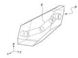
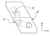
(2) 만든 피스는, 만드는 동안 지지되어야 하는 적어도 하나의 캔틸레버식 부분을 가질 수 있다. 첨부 도면의 도 1 내지 도 3을 참조할 수 있으며, 이들 도면은, 그 배향에 상관없이, 제조 동안 지지되어야 하는 면(F)이 항상 있는 제조될 피스(P)를 도시하며, 만약 지지되지 않는다면, 이 피스는 붕괴할 것이다.(2) The made piece may have at least one cantilevered part that must be supported during making. Reference may be made to FIGS. 1 to 3 of the accompanying drawings, which, regardless of their orientation, show the piece P to be manufactured, which always has a surface F to be supported during manufacture, if not supported , This piece will collapse.
(3) 제조될 피스는, 도 1 내지 도 3의 피스(P)의 경우처럼, 3차원 기하학적 모양의 경로(p)를 가질 수 도 있다. 이 경로는, 이러한 기하학적 모양으로 된 도구가 없기 때문에, 제대로 세척될 수 없다.(3) The piece to be manufactured may have a path p of a three-dimensional geometric shape, as in the case of the pieces P of FIGS. 1 to 3. This path cannot be cleaned properly, because there is no such geometrical tool.
출원인은 이들 문제점에 대한 해법을 찾아왔으며, 희생 소재 - 세라믹 또는 금속 광 경화성 조성물의 유기 부분에 의해서만 구성됨 - 로 만든 외피 또는 헐 내부에 피스를 만들면:Applicants have come up with solutions to these problems, and if they make a piece inside the sheath or hull made of sacrificial material-consisting only of the organic part of a ceramic or metal photocurable composition -:
- 각 층의 조사 후, 찾고 있는 피스를 에워싸는 경화된 희생 소재 블록, 피스를 얻기 위해 단지 디바인딩될 블록을 얻을 수 있으며; 피스의 세척은 그에 따라 더이상 페이스트 내에서 피스를 찾을 필요가 없으며 화학제품을 사용하여 피스를 세척할 필요가 없으므로 최적화되며;-After irradiation of each layer, a cured sacrificial material block surrounding the piece you are looking for, only a block to be debound to obtain the piece, can be obtained; The cleaning of the pieces is optimized accordingly since there is no longer a need to find the pieces in the paste and no need to clean the pieces using chemicals;
- 캔틸레버식 면을 가지며 그에 따라 만드는 동안 붕괴하기 쉬운 피스의 경우에, 경화된 희생 소재의 외피나 헐이 유리하게도 찾고 있는 지지부가 됨을 보장할 수 있으며;-In the case of a piece having a cantilevered surface and thus easy to collapse during construction, it can ensure that the outer shell or hull of the cured sacrificial material is advantageously the desired support;
- 그 표면으로 인도되는 빈 부분 또는 통로를 가지며 정확하게 세척되기 - 불가능한 것은 아니지만 - 어려운 피스의 경우에, 도구나 세척 화학제품을 삽입할 필요 없이 원하는 빈 부분 또는 통로를 얻기 위해 디바인딩하는 동안 희생 소재로 이때 채워지는 그러한 공간을 릴리스할 수 있다.-Has an empty part or passage leading to its surface and is cleaned accurately-not impossible-in the case of difficult pieces, sacrificial material during debinding to obtain the desired empty part or passage without the need to insert tools or cleaning chemicals You can release such a space that is filled at this time.
더 나아가, 본 발명은, 외피나 헐에 사용될 소재의 양이 과잉되지 않고 적절한 양을 제공함으로써 최적화될 수 있다는 보완적인 장점을 제공한다.Furthermore, the present invention provides a complementary advantage that the amount of material to be used for the sheath or hull is not excessive and can be optimized by providing an appropriate amount.
그에 따라, 본 발명은 먼저, 적층 가공 기술을 사용하여 세라믹 소재 및 금속 소재로부터 선택되는 적어도 하나의 소재로 만든 적어도 하나의 피스를 제조하는 방법에 관한 것이며, 그러한 하나 이상의 피스는 생소지 상태(green body state)로 형성되고, 그 후 디바인딩 및 소결 작업을 거치며, 이 방법은 다음의 단계:Accordingly, the present invention first relates to a method of manufacturing at least one piece made of at least one material selected from a ceramic material and a metal material using additive manufacturing technology, wherein such one or more pieces are green. body state), and then subjected to debinding and sintering, the method comprising the following steps:
(1) 컴퓨터 보조 설계에 의해, 제조될 피스 또는 동시에 제조될 피스들의 컴퓨터 모델을 만드는 단계;(1) by computer assisted design, creating a computer model of the pieces to be manufactured or pieces to be manufactured simultaneously;
(2) 작업 트레이 상에서, 세라믹 또는 금속 광 경화성 조성물(Ceramic Photocurable Composition or Metallic Photocurable Composition: CPC 또는 MPC)을 원료로 하는 제조될 상기 하나 이상의 피스를 형성하는 단계로서, 상기 조성물은:(2) forming, on a work tray, the one or more pieces to be prepared based on a ceramic or metal photocurable composition (CPC or MPC), the composition comprising:
- 적어도 하나의 분말 세라믹 소재 또는 적어도 하나의 분말 금속 소재로 구성되는 무기물 부분; 및 -An inorganic part consisting of at least one powder ceramic material or at least one powder metal material; And
- 상기 디바인딩 작업 동안 가열에 의해 파괴될 수 있으며 적어도 하나의 광 경화성 모노머 및/또는 올리고머 그리고 적어도 하나의 광 개시제를 포함하는 유기물 부분을 포함하는, 단계를 포함하며, 상기 방법이, 다음의 단계: -Comprising a portion of an organic material which can be destroyed by heating during the debinding operation and comprises at least one photocurable monomer and/or oligomer and at least one photoinitiator, the method comprising: :
- 층을 형성하기 위해 흐를 수 있는 현탁액(suspension)의 컨시스턴시(consistency)를 갖는 CPC 또는 MPC를 선택하는 단계;-Selecting a CPC or MPC with consistency of a suspension that can flow to form a layer;
- 광 경화성 층을 형성할 수 있으며 상기 디바인딩 작업 동안 가열에 의해 파괴될 수 있는 희생 유기 소재(SOM)를 준비하는 단계로서, 상기 SOM은 적어도 하나의 광 경화성 모노머 및/또는 올리고머 그리고 적어도 하나의 광 개시제를 포함하는, 단계;Preparing a sacrificial organic material (SOM) that can form a photocurable layer and can be destroyed by heating during the debinding operation, wherein the SOM comprises at least one photocurable monomer and/or oligomer and at least one Comprising a photoinitiator;
- 상기 하나 이상의 피스를 만들기 위해, 상기 작업 트레이 상에서, 서로의 위에 스택되는 SOM의 연속 층들을 형성하는 단계로서, SOM의 각 층은 그 다음 층을 도포하기 전 조사에 의해 경화되게 되며, CPC 또는 MPC를 원료로 하는 하나 이상의 적절하게 언급되는 피스는:-To make the one or more pieces, on the work tray, forming successive layers of SOM stacked on top of each other, each layer of SOM being cured by irradiation before applying the next layer, CPC or One or more suitably mentioned pieces based on MPC are:
- 경화된 SOM의 적어도 하나의 층에 이 층의 상부 표면으로부터 적어도 하나의 리세스를 기계 가공에 의해 형성하고; -At least one layer of the cured SOM is formed by machining at least one recess from the top surface of this layer;
- 상기 하나 이상의 리세스 내에, 상기 CPC 또는 MPC를 퇴적하여, 상기 하나 이상의 리세스를 채우며; -In the one or more recesses, depositing the CPC or MPC to fill the one or more recesses;
- 조사에 의해, 상기 하나 이상의 리세스 내에 위치하는 CPC 또는 MPC를 경화하여, 경화된 SOM의 인접 층과 동일한 레벨을 갖는 단단한 수평 표면을 얻음으로써 만들어지며, 각각의 리세스를 형성할 때, 각각의 리세스는 상기 컴퓨터 모델로부터 이전에 규정된 하나 이상의 패턴에 따라 범위가 정해지며, 각각의 리세스의 깊이(들)는 제조될 피스(들)의 연속성을 보장하기 위해 선택되는, 단계; 및 -By irradiation, curing CPC or MPC located within the one or more recesses to obtain a solid horizontal surface having the same level as the adjacent layer of the cured SOM, each forming a recess, respectively The recess of is delimited by one or more patterns previously defined from the computer model, the depth(s) of each recess being selected to ensure continuity of the piece(s) to be manufactured; And
- 경화된 층들이 스택되면, SOM에 내장되는 하나 이상의 그린 피스를 획득하는 단계로서, 그러한 그린 피스는, 그린 피스 또는 그린 피스들이 갇히는 SOM을 파괴하여 그린 피스 또는 그린 피스들을 릴리스시킨 후 그린 피스 또는 그린 피스들을 소결 작업에 제공하기 위해, 가열에 의해 디바인딩 작업을 거치는, 단계를 포함하는 것을 특징으로 한다.-When the cured layers are stacked, obtaining one or more green pieces embedded in the SOM, such green pieces destroying the green piece or the SOM in which the green pieces are trapped, releasing the green piece or green pieces, and then the green piece or It characterized in that it comprises a step of undergoing a debinding operation by heating to provide the green pieces to the sintering operation.
세라믹 소재는, 특히, 알루미나(Al2O3), 지르코니아(Zr02),지르코니아-강화된 알루미나, 알루미나-강화된 지르코니아, 지르콘(ZrSiO4), 이산화규소(SiO2), 수산화인회석(hydroxyapatite), 실리카 지르콘(ZrSiO4 + SiO2), 질화규소, 인산 삼칼슘(TCP), 질화알루미늄, 탄화규소, 코어디어라이트(cordierite) 및 멀라이트(mullite)로부터 선택되는 분말 소결 가능 세라믹 소재이다.Ceramic materials include, in particular, alumina (Al2 O3 ), zirconia (Zr02 ), zirconia-reinforced alumina, alumina-reinforced zirconia, zircon (ZrSiO4 ), silicon dioxide (SiO2 ), hydroxyapatite It is a powder sinterable ceramic material selected from silica zircon (ZrSiO4 + SiO2 ), silicon nitride, tricalcium phosphate (TCP), aluminum nitride, silicon carbide, cordierite and mullite.
금속 소재는, 특히 Al, Cu, Mg, Si, Ti, Zn, Sn, Ni 등과 같은 순금속, 그 합금 및 순금속과 그 합금의 혼합물로부터 선택되는 분말 소결 가능 금속 소재이다.The metal material is a powder sinterable metal material particularly selected from pure metals such as Al, Cu, Mg, Si, Ti, Zn, Sn, Ni and the like, and alloys and mixtures of pure metals and alloys thereof.
리세스는, SOM의 경화된 층의 전체 두께로 또는 층의 높이보다 낮은 높이로 형성되어야 할 수 있다. 리세스는 또한 층의 두께보다 높은 높이로, 예컨대 이전에 확산된 여러 층의 높이와 같은 높이로 형성되어야 할 수 있다.The recess may have to be formed with the total thickness of the cured layer of the SOM or with a height lower than the height of the layer. The recess may also have to be formed at a height higher than the thickness of the layer, for example, at a height equal to the height of several previously diffused layers.
제조될 하나 이상의 피스가 빈 부분을 포함할 때, 빈 부분은 피스의 외표면까지 인도되어 SOM이 디바인딩 작업 동안 릴리스될 수 있어야 한다.When one or more pieces to be manufactured include an empty portion, the empty portion must be guided to the outer surface of the piece so that the SOM can be released during the debinding operation.
본 발명에 따른 방법은, SOM의 동일 블록에 갇히게 될 여러 동일한 피스의 제조에 적용될 수 있다.The method according to the invention can be applied to the manufacture of several identical pieces that will be trapped in the same block of SOM.
스크레이핑(scraping)에 의해 층에서 확산되는 페이스티(pasty) SOM이 사용될 수 있거나, 경화될 SOM의 층을 매번 형성하기 위해 현탁액의 수조에 트레이를 담그며, 그에 따라 형성된 층을 스크레이핑함으로써 도포되는 현탁액의 SOM이 사용될 수 있다.Pasty SOM that diffuses from layer to layer by scraping can be used, or by dipping the tray in a water bath of the suspension to form a layer of SOM to be cured each time, and thus scraping the formed layer SOM of the suspension to be applied can be used.
제조될 피스(들)가 만드는 동안 지지되어야 하는 적어도 하나의 측방향 부분을 포함하는 경우에, 유리하게도, 경화 상태의 SOM의 형상의 컴퓨터 모델은 컴퓨터 보조 설계에 의해 미리 만들었으며, 이러한 형상은, 제조된 피스(들)가 이들을 만드는 동안 지지되도록 되어 있다.In the case where the piece(s) to be manufactured comprise at least one lateral part that must be supported during making, advantageously, the computer model of the shape of the cured SOM is pre-made by computer aided design, which shape, The manufactured piece(s) are intended to be supported while making them.
리세스(들)를 형성하기 위해, 기계 가공을 실행할 수 있다. 특히 1W와 3W 사이의 레이저 파워와, 1mm/s와 100mm/s 사이의 레이저 변위 속도를 설정하는 조건 하에서, 레이저 기계 가공을 또한 실행할 수 있다.Machining can be performed to form the recess(es). Laser machining can also be carried out, especially under the conditions of setting the laser power between 1W and 3W and the laser displacement speed between 1mm/s and 100mm/s.
또한, 각 기계 가공 단계에서, 특히 그러한 기계 가공이 행해짐과 동시에, 파편을 날려보내고 흡입할 수 있다.In addition, in each machining step, at the same time as such machining is performed in particular, debris can be blown out and sucked.
CPC 또는 MPC는 분배 노즐에 의해 하나 이상의 리세스 내에 도포될 수 있다.CPC or MPC can be applied in one or more recesses by a dispensing nozzle.
70mW와 700mW 사이의 레이저 파워와 1,000mm/s와 6,000mm/s 사이의 레이저 변위 속도를 설정하는 조건 하에서 리세스 내에 위치하는 CPC 또는 MPC의 층의 레이저 조사에 의한 경화와 SOM의 각 층의 레이저 조사에 의한 경화를 행할 수 있다.Curing by laser irradiation of a layer of CPC or MPC located in the recess under the conditions of setting the laser power between 70 mW and 700 mW and the laser displacement speed between 1,000 mm/s and 6,000 mm/s and laser of each layer of the SOM Curing by irradiation can be performed.
디바인딩 작업은 50℃와 800℃ 사이, 특히 100℃와 700℃ 사이의 온도에서 행해질 수 있다.The debinding operation can be performed at a temperature between 50°C and 800°C, especially between 100°C and 700°C.
본 발명은 또한, 앞서 규정한 바와 같이 적층 가공의 기술을 사용하는 방법에 의해 세라믹 소재와 금속 소재로부터 선택되는 적어도 하나의 소재로 만든 적어도 하나의 피스를 제조하는 머신에 관한 것이며, 이 머신은:The present invention also relates to a machine for producing at least one piece made of at least one material selected from a ceramic material and a metal material by a method using the technique of additive manufacturing as defined above, the machine comprising:
- 작업 표면을 포함하는 작업 트레이를 둘러싸는 프레임;-A frame surrounding a work tray comprising a work surface;
- 작업 표면에 면하는 조사 수단;-Irradiating means facing the working surface;
- 작업 트레이 상에, 희생 광 경화성 유기 소재(SOM)를 층들로 공급하고 확산하기 위한 수단;-Means for supplying and diffusing sacrificial photo-curable organic material (SOM) into layers on the working tray;
- 광 경화된 SOM의 층에 그 상부 부분으로부터 적어도 하나의 리세스를 형성할 수 있는 기계 가공 수단;-A machining means capable of forming at least one recess from the upper part of the layer of the photocured SOM;
- 상기 기계 가공 수단으로 인한 파편을 날려버리며 흡입하기 위한 수단;-Means for blowing and inhaling debris from the machining means;
- 흐를 수 있는 세라믹 또는 금속 광 경화성 조성물(CPC 또는 MPC)에 의해 광 경화된 SOM의 각 층에 형성된 하나 이상의 리세스를 채워서, 리세스된 층을 그에 따라 완성하기 위한 수단;Means for filling one or more recesses formed in each layer of the SOM photocured by a flowable ceramic or metal photocurable composition (CPC or MPC), thereby completing the recessed layer accordingly;
- 작업 트레이 위에 배치되며, 일단 확산된 SOM의 각 층을 경화하기 위해 이 각 층에 조사할 수 있으며, 경화된 SOM의 연속 층에 만들어진 리세스 내에 일단 위치하는 CPC 또는 MPC를 경화하기 위해 이 CPC 또는 MPC에 조사할 수 있는 조사 수단을 포함하는 것을 특징으로 한다.-Placed on a work tray, each layer of diffused SOM can be irradiated to each layer to cure, and this CPC is used to cure CPCs or MPCs once located within recesses made in a continuous layer of cured SOM. Or it characterized in that it comprises an investigation means that can be irradiated to the MPC.
페이스트 형태하의 SOM을 층들로 도포할 수 있는 그러한 머신은 갠트리(gantry)를 포함할 수 있으며, 갠트리는 적어도 하나의 스크레이핑 블레이드를 가지며, 작업 표면 위에서 프레임 상을 이동할 수 있어서 스크레이핑 블레이드(들)의 자유 에지가 작업 표면 상에서 SOM 페이스트의 층을 확산시킬 수 있거나,Such a machine capable of applying the SOM in the form of a paste in layers may include a gantry, the gantry has at least one scraping blade, and is capable of moving on the frame over the working surface so that the scraping blade ( The free edge of the field) can diffuse a layer of SOM paste on the working surface, or
SOM은, SOM 상을 통과할 때 SOM을 균일한 층으로 확산시키는 적어도 하나의 스크레이핑 블레이드 앞에서 이동할 수 있는 적어도 하나의 분배 노즐에 의해 공급된다.The SOM is supplied by at least one dispensing nozzle that can move in front of at least one scraping blade that diffuses the SOM into a uniform layer as it passes over the SOM.
현탁액의 형태하에서 SOM을 층들로 도포할 수 있는 그러한 머신은 그러한 현탁액으로 채워질 탱크 - 여기서 작업 트레이는 작업 트레이 상에서 각 단계에서 조사될 층을 형성하기 위해 단계적으로 낮춰질 수 있음 - 및 현탁액이 조사될 전체 표면 상에서 분배됨을 보장하기 위한 리코터(recoater)를 포함할 수 있다.Such a machine capable of applying SOM in layers in the form of a suspension is a tank to be filled with such suspension, wherein the working tray can be lowered step by step to form a layer to be irradiated at each stage on the working tray-and the suspension is to be irradiated. Recoaters may be included to ensure distribution over the entire surface.
작업 표면상에 적어도 하나의 CPC 또는 MPC를 공급하기 위한 수단은, 대응하는 조성물을 대응하는 리세스에 도포하기 위해 대응하는 리세스 위에서 이동할 수 있는 적어도 하나의 분배 노즐로 구성될 수 있다.The means for supplying the at least one CPC or MPC on the working surface may consist of at least one dispensing nozzle movable on the corresponding recess to apply the corresponding composition to the corresponding recess.
제1 실시예에 따라, 노즐 또는 노즐 중 적어도 하나에는 탱크, 특히 피스톤 공급 탱크에 연결된 호스에 의해 SOM 또는 CPC 또는 MPC가 공급될 수 있다.According to the first embodiment, at least one of the nozzles or nozzles may be supplied with SOM or CPC or MPC by a hose connected to a tank, especially a piston supply tank.
제2 실시예에 따라, 노즐 또는 노즐 중 적어도 하나에는 그 상부 부분을 형성하는 카트리지에 의해 SOM 또는 CPC 또는 MPC가 공급될 수 있으며, 그러한 카트리지는 SOM 또는 CPC 또는 MPC의 비축물을 포함하며, 머신상에 장착할 수 있는 공급 탱크로부터 다시 채울 수 있거나, 비어 있을 때 가득 찬 카트리지로 교체할 수 있으며, 그러한 교체는 로봇 아암에 의해 보장될 수 있다.According to the second embodiment, at least one of the nozzles or nozzles may be supplied with SOM or CPC or MPC by cartridges forming an upper portion thereof, the cartridge comprising a stockpile of SOM or CPC or MPC, and the machine It can be refilled from an on-load supply tank or replaced with a full cartridge when empty, and such replacement can be ensured by a robot arm.
노즐 또는 노즐 중 적어도 하나는,The nozzle or at least one of the nozzles,
- 로봇 아암을 사용하거나; 또는-Use a robot arm; or
- 작업 트레이의 수평 축(x)을 따라 노즐을 이동시킬 수 있게 하는 슬라이드와, 작업 트레이의 수평 축(y)을 따라 노즐을 이동시킬 수 있게 하는 슬라이드 모두를 갖는 갠트리 상에서; 또는On a gantry with both a slide allowing the nozzle to move along the horizontal axis (x) of the working tray and a slide enabling the nozzle to move along the horizontal axis (y) of the working tray; or
- 적어도 하나의 스크레이핑 블레이드의 수평 진행 축(x)을 따라 노즐의 변위를 가능하게 하기 위해 그러한 스크레이핑 블레이드를 가지며, 수평 축(y)을 따라 노즐을 이동시킬 수 있게 하는 슬라이드를 또한 포함하는 갠트리 상에서 이동할 수 있게 장착할 수 있다.A slide having such a scraping blade to enable displacement of the nozzle along the horizontal traveling axis (x) of the at least one scraping blade, and also allowing the nozzle to move along the horizontal axis (y) It can be mounted to be movable on the containing gantry.
본 발명의 요지를 더 잘 예시하기 위해, 본 발명의 특정 실시예는, 첨부된 도면을 참조하여, 지시 및 비제한적인 목적으로, 이하에서 기재될 것이다.To better illustrate the subject matter of the present invention, certain embodiments of the present invention will be described below with reference to the accompanying drawings, for instructional and non-limiting purposes.
도 1은, 3차원 원통형 통로를 포함하는 제조될 피스의 개략 사시도이다.
도 2 및 도 3은, 각각 yz 및 xz 평면에서의 도 1의 피스의 개략도이다.
도 4는, 본 발명에 따라 제조되는 피스의 개략 횡단면도이다.
도 5는, zy 및 zx 평면에서의, 디바인딩 작업 전 본 발명에 따라 제조되는 피스의 개략도를 도시한다.
도 6 및 도 7은, 각각 디바인딩 작업 전 및 후의 도 5의 피스의 개략 사시도이다.
도 8 내지 도 11은, 희생 광 경화성 소재의 층을 형성하기 위한 연속 단계를 예시한다.
도 12 및 도 13은, 희생 유기 소재와 광 경화성 소재에 의해 모두 구성되는 층의 형성을 예시한다.1 is a schematic perspective view of a piece to be manufactured comprising a three-dimensional cylindrical passage.
2 and 3 are schematic views of the piece of FIG. 1 in the yz and xz planes, respectively.
4 is a schematic cross-sectional view of a piece manufactured according to the present invention.
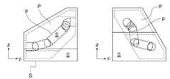
5 shows a schematic view of a piece made according to the invention before debinding operation in the zy and zx planes.
6 and 7 are schematic perspective views of the piece of FIG. 5 before and after debinding, respectively.
8 to 11 illustrate successive steps for forming a layer of sacrificial photo-curable material.
12 and 13 illustrate the formation of a layer composed of both a sacrificial organic material and a photocurable material.
도 4 내지 도 6을 참조하면, 경화된 희생 유기 소재로 만든 외피 또는 헐(S) 내에서 본 발명에 따른 피스(P)의 형성이 예시되며, 통로(p)는 또한 희생 유기 소재(S)로 채워짐을 알 수 있다.4 to 6, the formation of the piece P according to the present invention is illustrated in an outer shell or hull made of a cured sacrificial organic material, and the passage p is also a sacrificial organic material S It can be seen that it is filled with.
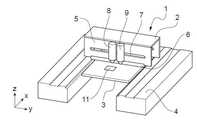
도 8을 참조하면, 그린 피스를 제조하기 위한 머신(1)이 개략적으로 도시되어 있으며, 이 머신은, 수평 작업 트레이(3)의 작업 표면상에서 페이스트 층을 스크레이핑하기 위한 디바이스(2)를 포함한다.Referring to Fig. 8, a
머신의 프레임(4) 상에 슬라이딩 가능하게 장착되는 스크레이핑 디바이스(2)는, 수평 스크레이핑 에지를 가지며 도 8을 참조할 때 전방, 즉 수평 축(x)을 따라 이동하는 스크레이핑 블레이드(6)를 그 전방 부분에서 지니는 갠트리(5)를 포함한다.The
갠트리(5)의 전방 수직 벽은 수평 슬라이드(7)를 가지며, 이 슬라이드를 따라, 2개의 노즐(8, 9) - 광 경화성 희생 유기 소재를 퇴적하기 위한 하나(8)와, 세라믹 광 경화성 조성물을 퇴적하기 위한 다른 하나(9) - 을 축(x)에 수직인 수평 축(y)을 따라 이동할 수 있다.The front vertical wall of the
도 11에서, 레이저 빔을 보내기 위한 갈바노메트릭 헤드(10)가 또한 도시된다.In Fig. 11, a
도 8Fig. 8
희생 유기 소재의 층(11)이, 축(x)을 따라 스크레이핑 디바이스(2)를 이동시키며 축(y)을 따라 노즐(8)을 이동시킴으로써, 작업 트레이(3)의 작업 표면 상에 퇴적된다.A
도 9Fig. 9
전방 이동에 의해, 스크레이핑 디바이스(2)는, 블레이드(6)를 이동시킴으로써 희생 유기 소재의 층(11)을 평평하게 한다.By forward movement, the
도 10Fig. 10
스크레이핑 디바이스(2)는 그 초기 위치로 복귀하여 상승한다.The
도 11Fig. 11
그에 따라 퇴적된 층(11)은, 레이저 빔을 적용함으로써 중합되며, 갈바노메트릭 헤드(10)가 사용된다.The
도 12Fig. 12
경화된 층(11)의 레이저 기계 가공이 리세스(12)를 이 층에 형성하기 위해 실행되며, 이 레이저 기계 가공 작업은 레이저 조사와 함께 파편을 날려버리고 흡입함으로써 실행된다.Laser machining of the cured
도 13Fig. 13
제2 노즐(9)을 사용하여, 광 경화성 세라믹 조성물(13)이 리세스 내에 퇴적되며, 이 조성물은, 레이저 빔을 적용함으로써 중합된다(갈바노메트릭 헤드(10)가 사용된다).Using the
희생 유기 소재 및 세라믹 소재의 경화된 층의 형성을 기재하였으며 이들 소재 모두는 광 경화된다.The formation of a cured layer of sacrificial organic material and ceramic material has been described and both of these materials are photocured.
찾고 있는 피스는, 광 경화된 희생 유기 소재의 층을 쌓아서 만들며, 광 경화성 세라믹 소재로 채워지고자 하는 리세스는 이전에 경화된 희생 유기 소재의 적어도 하의 층에서 뚫리며, 희생 유기 소재의 층 상에서의 리세스의 깊이와 그 위치는, 찾고 있는 세라믹 피스의 형성을 보장하기 위해 선택된다.The piece you are looking for is made by layering a layer of photo-cured sacrificial organic material, and the recess to be filled with the photo-curable sacrificial organic material is drilled in at least a layer of the previously cured sacrificial organic material, and on the layer of the sacrificial organic material. The depth of the recess and its location are selected to ensure the formation of the ceramic piece you are looking for.
Claims (16)
Translated fromKorean(1) 컴퓨터 보조 설계에 의해, 제조될 피스 또는 동시에 제조될 피스들의 컴퓨터 모델을 만드는 단계;
(2) 작업 트레이 상에서, 세라믹 또는 금속 광 경화성 조성물(Ceramic Photocurable Composition or Metallic Photocurable Composition: CPC 또는 MPC)을 원료로 하는 제조될 상기 하나 이상의 피스를 형성하는 단계로서, 상기 조성물은:
- 적어도 하나의 분말 세라믹 소재 또는 적어도 하나의 분말 금속 소재로 구성되는 무기물 부분; 및
- 디바인딩 작업 동안 가열에 의해 파괴될 수 있으며 적어도 하나의 광 경화성 모노머 및/또는 올리고머 그리고 적어도 하나의 광 개시제를 포함하는 유기물 부분을 포함하는, 단계를 포함하며, 상기 방법은
다음의 단계:
- 층을 형성하기 위해 흐를 수 있는 현탁액(suspension)의 컨시스턴시(consistency)를 갖는 CPC 또는 MPC를 선택하는 단계;
- 광 경화성 층을 형성할 수 있으며 디바인딩 작업 동안 가열에 의해 파괴될 수 있는 희생 유기 소재(SOM)를 준비하는 단계로서, 상기 SOM은 적어도 하나의 광 경화성 모노머 및/또는 올리고머 그리고 적어도 하나의 광 개시제를 포함하는, 단계;
- 상기 하나 이상의 피스를 만들기 위해, 상기 작업 트레이 상에서, 서로의 위에 스택되는 SOM의 연속 층들을 형성하는 단계로서, SOM의 각 층은 그 다음 층을 도포하기 전 조사에 의해 경화되게 되며, CPC 또는 MPC를 원료로 하는 하나 이상의 적절하게 언급되는 피스는:
- 경화된 SOM의 적어도 하나의 층에 이 층의 상부 표면으로부터 적어도 하나의 리세스를 기계 가공에 의해 형성하고;
- 상기 하나 이상의 리세스 내에, 상기 CPC 또는 MPC를 퇴적하여, 상기 하나 이상의 리세스를 채우며;
- 조사에 의해, 상기 하나 이상의 리세스 내에 위치하는 CPC 또는 MPC를 경화하여, 경화된 SOM의 인접 층과 동일한 레벨을 갖는 단단한 수평 표면을 얻음으로써 만들어지며, 각각의 리세스를 형성할 때, 각각의 리세스는 컴퓨터 모델로부터 이전에 규정된 하나 이상의 패턴에 따라 범위가 정해지며, 각각의 리세스의 깊이(들)는 제조될 피스(들)의 연속성을 보장하기 위해 선택되는, 단계; 및
- 경화된 층들이 스택되면, 상기 SOM에 내장되는 하나 이상의 그린 피스를 획득하는 단계로서, 상기 그린 피스들은, 그린 피스 또는 그린 피스들이 갇히는 상기 SOM을 파괴하여 상기 그린 피스 또는 상기 그린 피스들을 릴리스시킨 후 상기 그린 피스 또는 상기 그린 피스들을 소결 작업에 제공하기 위해, 가열에 의해 디바인딩 작업을 거치는, 단계를 포함하는 것을 특징으로 하는, 방법.A method of manufacturing at least one piece made of at least one material selected from ceramic materials and metal materials using additive processing technology, wherein the one or more pieces are formed in a green body state After that, after debinding and sintering, the method includes the following steps:
(1) by computer assisted design, creating a computer model of the pieces to be manufactured or pieces to be manufactured simultaneously;
(2) On the working tray, forming the one or more pieces to be prepared based on a ceramic or metal photocurable composition (CPC or MPC), the composition comprising:
-An inorganic part consisting of at least one powder ceramic material or at least one powder metal material; And
-Comprising a portion of an organic material which can be destroyed by heating during the debinding operation and comprises at least one photocurable monomer and/or oligomer and at least one photoinitiator, the method comprising
Next steps:
-Selecting a CPC or MPC with consistency of the suspension that can flow to form a layer;
Preparing a sacrificial organic material (SOM), which can form a photocurable layer and can be destroyed by heating during a debinding operation, wherein the SOM comprises at least one photocurable monomer and/or oligomer and at least one light Comprising an initiator;
-To make the one or more pieces, on the work tray, forming successive layers of SOM stacked on top of each other, each layer of SOM being cured by irradiation before applying the next layer, CPC or One or more suitably mentioned pieces based on MPC are:
-At least one layer of the cured SOM is formed by machining at least one recess from the top surface of this layer;
-In the one or more recesses, depositing the CPC or MPC to fill the one or more recesses;
-By irradiation, curing CPC or MPC located within the one or more recesses to obtain a solid horizontal surface having the same level as the adjacent layer of the cured SOM, each forming a recess, respectively The recess of is scoped according to one or more patterns previously defined from the computer model, the depth(s) of each recess being selected to ensure continuity of the piece(s) to be manufactured; And
-When the cured layers are stacked, obtaining one or more green pieces embedded in the SOM, wherein the green pieces release the green piece or the green pieces by destroying the green piece or the SOM in which the green pieces are trapped And then subjecting the green piece or the green pieces to a debinding operation by heating to provide the sintering operation.
- 작업 표면을 포함하는 작업 트레이(3)를 둘러싸는 프레임(4);
- 상기 작업 표면에 면하는 조사 수단;
- 상기 작업 트레이(3) 상에, 희생 광 경화성 유기 소재(SOM)를 층들로 공급하고 확산하기 위한 수단;
- 광 경화된 SOM의 층(11)에 이 층의 상부 부분으로부터 적어도 하나의 리세스(12)를 형성할 수 있는 기계 가공 수단;
- 상기 기계 가공 수단으로 인한 파편을 날려버리며 흡입하기 위한 수단;
- 흐를 수 있는 세라믹 또는 금속 광 경화성 조성물(CPC 또는 MPC)에 의해 광 경화된 SOM의 각 층(11)에 형성된 하나 이상의 리세스(12)를 채워서, 리세스된 층을 그에 따라 완성하기 위한 수단;
- 상기 작업 트레이(3) 위에 배치되며, 일단 확산된 SOM의 각 층을 경화하기 위해 이 각 층에 조사할 수 있으며, 경화된 SOM의 연속 층들(11)에 만들어진 상기 리세스들(12) 내에 일단 위치하는 상기 CPC 또는 MPC를 경화하기 위해 상기 CPC 또는 MPC에 조사할 수 있는 조사 수단(10)을 포함하는 것을 특징으로 하는, 머신.A machine for manufacturing at least one piece made of at least one material selected from ceramic materials and metal materials by a method using the technique of additive manufacturing as described in claim 1 or claim 2,
A frame 4 surrounding a work tray 3 comprising a work surface;
-Irradiating means facing the working surface;
-Means for supplying and diffusing sacrificial photo-curable organic material (SOM) into layers on said working tray 3;
-A machining means capable of forming at least one recess 12 from the upper part of this layer in the layer 11 of the photocured SOM;
-Means for blowing and inhaling debris from the machining means;
Means for filling one or more recesses 12 formed in each layer 11 of the photocured SOM by a flowable ceramic or metal photocurable composition (CPC or MPC), thereby completing the recessed layer accordingly ;
-Placed on the work tray 3, each layer of the diffused SOM can be irradiated on each of these layers to cure, and within the recesses 12 made on the continuous layers 11 of the cured SOM Machine, characterized in that it comprises an irradiating means (10) capable of irradiating the CPC or MPC to cure the CPC or MPC once located.
상기 SOM이, 상기 SOM 상을 통과할 때 상기 SOM을 균일한 층으로 확산시키는 적어도 하나의 스크레이핑 블레이드(6) 앞에서 이동할 수 있는 적어도 하나의 분배 노즐(8)에 의해 공급되는 것을 특징으로 하는, 머신.The method according to claim 10, wherein the SOM in the form of a paste can be applied in layers, the machine comprising a gantry (5), the gantry having at least one scraping blade (6), the working surface. From above it is possible to move on the frame 4 so that the free edge of one or more scraping blades 6 can diffuse the layers of SOM paste on the working surface,
Characterized in that the SOM is supplied by at least one dispensing nozzle (8) that is movable in front of at least one scraping blade (6) that diffuses the SOM into a uniform layer when passing over the SOM. , machine.
노즐들 또는 노즐들 중 적어도 하나는,
- 로봇 아암을 사용하거나; 또는
- 상기 작업 트레이의 수평 축(x)을 따라 노즐을 이동시킬 수 있게 하는 슬라이드와, 상기 작업 트레이의 수평 축(y)을 따라 노즐을 이동시킬 수 있게 하는 슬라이드 모두를 갖는 갠트리 상에서; 또는
- 적어도 하나의 스크레이핑 블레이드(6)의 수평 축(x)을 따라 노즐의 변위를 가능하게 하기 위해 상기 적어도 하나의 스크레이핑 블레이드를 가지는, 그리고 상기 수평 축(y)을 따라 노즐을 이동시킬 수 있게 하는 슬라이드(7)를 또한 포함하는 갠트리(5) 상에서,
이동할 수 있게 장착되는 것을 특징으로 하는, 머신.The method according to claim 11,
The nozzles or at least one of the nozzles,
-Use a robot arm; or
-On a gantry with both a slide allowing the nozzle to move along the horizontal axis (x) of the working tray and a slide enabling the nozzle to move along the horizontal axis (y) of the working tray; or
-Having the at least one scraping blade to enable displacement of the nozzle along the horizontal axis (x) of the at least one scraping blade (6), and moving the nozzle along the horizontal axis (y) On the gantry 5, which also includes a slide 7 to enable
Machine, characterized in that it is mounted movably.
Applications Claiming Priority (2)
| Application Number | Priority Date | Filing Date | Title |
|---|---|---|---|
| FR1770870AFR3070135B1 (en) | 2017-08-18 | 2017-08-18 | METHOD AND MACHINE FOR MANUFACTURING PARTS OF CERAMIC OR METALLIC MATERIAL BY THE TECHNIQUE OF ADDITIVE PROCESSES |
| FR1770870 | 2017-08-18 |
Publications (2)
| Publication Number | Publication Date |
|---|---|
| KR20190019852A KR20190019852A (en) | 2019-02-27 |
| KR102142507B1true KR102142507B1 (en) | 2020-08-07 |
Family
ID=60138648
Family Applications (1)
| Application Number | Title | Priority Date | Filing Date |
|---|---|---|---|
| KR1020180095598AActiveKR102142507B1 (en) | 2017-08-18 | 2018-08-16 | Method and machine for manufacturing pieces made of ceramic or metallic material by the technique of additive manufacturing |
Country Status (10)
| Country | Link |
|---|---|
| US (2) | US11090725B2 (en) |
| EP (1) | EP3444049B1 (en) |
| JP (1) | JP6748162B2 (en) |
| KR (1) | KR102142507B1 (en) |
| CN (1) | CN109396432B (en) |
| ES (1) | ES2779958T3 (en) |
| FR (1) | FR3070135B1 (en) |
| PT (1) | PT3444049T (en) |
| RU (1) | RU2701263C1 (en) |
| UA (1) | UA120483C2 (en) |
Families Citing this family (2)
| Publication number | Priority date | Publication date | Assignee | Title |
|---|---|---|---|---|
| EP3725435A1 (en)* | 2019-04-17 | 2020-10-21 | Siemens Aktiengesellschaft | Production of a metal object |
| CN114193763A (en)* | 2021-12-01 | 2022-03-18 | 中国钢研科技集团有限公司 | 3D printing method and device for multi-material selective area powder laying selective area sintering |
Citations (4)
| Publication number | Priority date | Publication date | Assignee | Title |
|---|---|---|---|---|
| JP2009006509A (en) | 2007-06-26 | 2009-01-15 | Panasonic Electric Works Co Ltd | Manufacturing method and manufacturing apparatus for three-dimensional shaped object |
| JP2010037599A (en) | 2008-08-05 | 2010-02-18 | Panasonic Electric Works Co Ltd | Apparatus for producing laminated object |
| JP2016203425A (en)* | 2015-04-17 | 2016-12-08 | セイコーエプソン株式会社 | Three-dimensional structure manufacturing method, three-dimensional structure manufacturing apparatus, and three-dimensional structure |
| JP2016221894A (en)* | 2015-06-02 | 2016-12-28 | セイコーエプソン株式会社 | Method for manufacturing three-dimensional molded object, apparatus for manufacturing three-dimensional molded object and three-dimensional molded object |
Family Cites Families (20)
| Publication number | Priority date | Publication date | Assignee | Title |
|---|---|---|---|---|
| JPH1044248A (en)* | 1996-07-29 | 1998-02-17 | Roland D G Kk | 3D modeling method |
| AU2003900180A0 (en)* | 2003-01-16 | 2003-01-30 | Silverbrook Research Pty Ltd | Method and apparatus (dam001) |
| RU2269416C2 (en)* | 2004-02-17 | 2006-02-10 | Московский государственный технический университет им. Н.Э. Баумана (МГТУ им. Н.Э. Баумана) | Method for manufacturing products by means of laser stereo-lithography and device for realization of said method |
| JP2009084619A (en)* | 2007-09-28 | 2009-04-23 | Jsr Corp | Photocurable composition for micro stereolithography, metal model, and manufacturing method thereof |
| CN101422963A (en)* | 2008-10-14 | 2009-05-06 | 欧客思国际有限公司 | Method and equipment for manufacturing three-dimensional workpiece |
| EP2519193A1 (en) | 2009-12-30 | 2012-11-07 | Synthes GmbH | Intergrated multi-material implants and methods of manufacture |
| EP2529694B1 (en)* | 2011-05-31 | 2017-11-15 | Ivoclar Vivadent AG | Method for generative production of ceramic forms by means of 3D jet printing |
| SE536670C2 (en) | 2011-08-26 | 2014-05-13 | Digital Metal Ab | Layer-based manufacture of free-form micro-components of multimaterial |
| US10059056B2 (en)* | 2012-02-01 | 2018-08-28 | Nscrypt, Inc. | Micro-dispensing multi-layered 3D objects with curing steps |
| US20150034266A1 (en)* | 2013-08-01 | 2015-02-05 | Siemens Energy, Inc. | Building and repair of hollow components |
| DE102014004870B4 (en)* | 2014-04-04 | 2022-06-02 | Airbus Defence and Space GmbH | Support device and manufacturing device for a generative manufacturing process, as well as generative manufacturing process that can be carried out with it |
| WO2015171182A1 (en)* | 2014-05-04 | 2015-11-12 | Eoplex Limited | Multi-material three dimensional printer |
| US9808865B2 (en)* | 2015-01-30 | 2017-11-07 | Solar Turbines Incorporated | Method for manufacturing a metallic component |
| JP6669985B2 (en) | 2015-11-12 | 2020-03-18 | セイコーエプソン株式会社 | Manufacturing method of three-dimensional objects |
| US11059101B2 (en)* | 2016-02-11 | 2021-07-13 | Ddm Systems, Inc. | Conformal material and support structures for additive manufacturing systems and methods of use thereof |
| CN106799835A (en)* | 2017-02-10 | 2017-06-06 | 深圳摩方新材科技有限公司 | A kind of photocuring 3D printer based on dot matrix display |
| US10343214B2 (en)* | 2017-02-17 | 2019-07-09 | General Electric Company | Method for channel formation in binder jet printing |
| CN108790150B (en)* | 2017-04-26 | 2021-02-19 | 苏州苏大维格科技集团股份有限公司 | 3D printing system and 3D printing method |
| FR3070134B1 (en)* | 2017-08-18 | 2019-08-16 | S.A.S 3Dceram-Sinto | METHOD AND MACHINE FOR MANUFACTURING AT LEAST ONE PIECE OF AT LEAST ONE CERAMIC AND / OR METALLIC MATERIAL BY THE TECHNIQUE OF ADDITIVE PROCESSES |
| FR3074800B1 (en)* | 2017-12-11 | 2019-11-01 | S.A.S 3Dceram-Sinto | PROCESS FOR MANUFACTURING PIECES OF CERAMIC MATERIAL BY THE TECHNIQUE OF ADDITIVE PROCESSES |
- 2017
- 2017-08-18FRFR1770870Apatent/FR3070135B1/enactiveActive
- 2018
- 2018-06-20ESES18178869Tpatent/ES2779958T3/enactiveActive
- 2018-06-20EPEP18178869.6Apatent/EP3444049B1/enactiveActive
- 2018-06-20PTPT181788696Tpatent/PT3444049T/enunknown
- 2018-08-14UAUAA201808706Apatent/UA120483C2/enunknown
- 2018-08-15JPJP2018152985Apatent/JP6748162B2/enactiveActive
- 2018-08-16KRKR1020180095598Apatent/KR102142507B1/enactiveActive
- 2018-08-16CNCN201810935477.7Apatent/CN109396432B/enactiveActive
- 2018-08-17RURU2018129992Apatent/RU2701263C1/enactive
- 2018-08-20USUS15/999,028patent/US11090725B2/enactiveActive
- 2021
- 2021-08-09USUS17/444,695patent/US20210362231A1/ennot_activeAbandoned
Patent Citations (4)
| Publication number | Priority date | Publication date | Assignee | Title |
|---|---|---|---|---|
| JP2009006509A (en) | 2007-06-26 | 2009-01-15 | Panasonic Electric Works Co Ltd | Manufacturing method and manufacturing apparatus for three-dimensional shaped object |
| JP2010037599A (en) | 2008-08-05 | 2010-02-18 | Panasonic Electric Works Co Ltd | Apparatus for producing laminated object |
| JP2016203425A (en)* | 2015-04-17 | 2016-12-08 | セイコーエプソン株式会社 | Three-dimensional structure manufacturing method, three-dimensional structure manufacturing apparatus, and three-dimensional structure |
| JP2016221894A (en)* | 2015-06-02 | 2016-12-28 | セイコーエプソン株式会社 | Method for manufacturing three-dimensional molded object, apparatus for manufacturing three-dimensional molded object and three-dimensional molded object |
Also Published As
| Publication number | Publication date |
|---|---|
| EP3444049A2 (en) | 2019-02-20 |
| KR20190019852A (en) | 2019-02-27 |
| JP6748162B2 (en) | 2020-08-26 |
| JP2019034551A (en) | 2019-03-07 |
| CN109396432A (en) | 2019-03-01 |
| EP3444049A3 (en) | 2019-02-27 |
| US20210362231A1 (en) | 2021-11-25 |
| PT3444049T (en) | 2020-03-11 |
| FR3070135B1 (en) | 2019-08-16 |
| UA120483C2 (en) | 2019-12-10 |
| US11090725B2 (en) | 2021-08-17 |
| EP3444049B1 (en) | 2020-02-05 |
| US20190054528A1 (en) | 2019-02-21 |
| CN109396432B (en) | 2021-03-30 |
| RU2701263C1 (en) | 2019-09-25 |
| FR3070135A1 (en) | 2019-02-22 |
| ES2779958T3 (en) | 2020-08-20 |
Similar Documents
| Publication | Publication Date | Title |
|---|---|---|
| US6193922B1 (en) | Method for making a three-dimensional body | |
| KR102142505B1 (en) | Method and machine for manufacturing at least one piece made of at least one ceramic and/or metallic material by the technique of additive manufacturing | |
| JP6974466B2 (en) | Integrated casting core-shell structure for manufacturing casting components with thin root components | |
| JP6996822B2 (en) | Integrated casting core-shell structure for manufacturing casting components with non-linear holes | |
| JP6660969B2 (en) | A method of manufacturing a piece by an additive manufacturing technique by processing a paste, in which the supply of the paste is improved, and a manufacturing machine for performing the method | |
| JP7099792B2 (en) | Integrated casting core-shell structure with printed tubes for manufacturing cast parts | |
| JP7071367B2 (en) | Integrated casting core / shell structure for manufacturing cast parts with cooling holes in inaccessible locations | |
| JP6884862B2 (en) | Integrated casting core shell structure and filter for manufacturing cast parts | |
| CN110494238A (en) | The increasing material manufacturing carried out using the heavy applicator with the heavy applicator blade that can be replaced in situ | |
| JP6384826B2 (en) | Three-dimensional additive manufacturing apparatus, three-dimensional additive manufacturing method, and three-dimensional additive manufacturing program | |
| WO2014208743A1 (en) | Three-dimensional shaped body and support formation method | |
| CN120133539A (en) | Method for producing a molded layered product | |
| JP6482006B2 (en) | 3D modeling equipment | |
| CN107148336A (en) | Method, device and recoating module for manufacturing three-dimensional objects | |
| WO2015141782A1 (en) | Print head unit, three-dimensional additive layer manufacturing device, three-dimensional additive layer manufacturing method, and manufacturing product | |
| KR102142507B1 (en) | Method and machine for manufacturing pieces made of ceramic or metallic material by the technique of additive manufacturing | |
| HK40024447A (en) | Molding method and apparatus, particularly applicable to metal and/or ceramics |
Legal Events
| Date | Code | Title | Description |
|---|---|---|---|
| PA0109 | Patent application | St.27 status event code:A-0-1-A10-A12-nap-PA0109 | |
| A201 | Request for examination | ||
| P11-X000 | Amendment of application requested | St.27 status event code:A-2-2-P10-P11-nap-X000 | |
| P13-X000 | Application amended | St.27 status event code:A-2-2-P10-P13-nap-X000 | |
| PA0201 | Request for examination | St.27 status event code:A-1-2-D10-D11-exm-PA0201 | |
| PG1501 | Laying open of application | St.27 status event code:A-1-1-Q10-Q12-nap-PG1501 | |
| D13-X000 | Search requested | St.27 status event code:A-1-2-D10-D13-srh-X000 | |
| D14-X000 | Search report completed | St.27 status event code:A-1-2-D10-D14-srh-X000 | |
| E902 | Notification of reason for refusal | ||
| PE0902 | Notice of grounds for rejection | St.27 status event code:A-1-2-D10-D21-exm-PE0902 | |
| T11-X000 | Administrative time limit extension requested | St.27 status event code:U-3-3-T10-T11-oth-X000 | |
| P11-X000 | Amendment of application requested | St.27 status event code:A-2-2-P10-P11-nap-X000 | |
| P13-X000 | Application amended | St.27 status event code:A-2-2-P10-P13-nap-X000 | |
| E701 | Decision to grant or registration of patent right | ||
| PE0701 | Decision of registration | St.27 status event code:A-1-2-D10-D22-exm-PE0701 | |
| GRNT | Written decision to grant | ||
| PR0701 | Registration of establishment | St.27 status event code:A-2-4-F10-F11-exm-PR0701 | |
| PR1002 | Payment of registration fee | St.27 status event code:A-2-2-U10-U11-oth-PR1002 Fee payment year number:1 | |
| PG1601 | Publication of registration | St.27 status event code:A-4-4-Q10-Q13-nap-PG1601 | |
| P22-X000 | Classification modified | St.27 status event code:A-4-4-P10-P22-nap-X000 | |
| P22-X000 | Classification modified | St.27 status event code:A-4-4-P10-P22-nap-X000 | |
| P22-X000 | Classification modified | St.27 status event code:A-4-4-P10-P22-nap-X000 | |
| PR1001 | Payment of annual fee | St.27 status event code:A-4-4-U10-U11-oth-PR1001 Fee payment year number:4 | |
| PR1001 | Payment of annual fee | St.27 status event code:A-4-4-U10-U11-oth-PR1001 Fee payment year number:5 | |
| R18-X000 | Changes to party contact information recorded | St.27 status event code:A-5-5-R10-R18-oth-X000 | |
| PR1001 | Payment of annual fee | St.27 status event code:A-4-4-U10-U11-oth-PR1001 Fee payment year number:6 |