KR102138725B1 - Upper airway spraying device for coating chemical liquid into oral cavity and nasal cavity - Google Patents
Upper airway spraying device for coating chemical liquid into oral cavity and nasal cavityDownload PDFInfo
- Publication number
- KR102138725B1 KR102138725B1KR1020180045519AKR20180045519AKR102138725B1KR 102138725 B1KR102138725 B1KR 102138725B1KR 1020180045519 AKR1020180045519 AKR 1020180045519AKR 20180045519 AKR20180045519 AKR 20180045519AKR 102138725 B1KR102138725 B1KR 102138725B1
- Authority
- KR
- South Korea
- Prior art keywords
- tube
- user
- container
- oral
- chemical solution
- Prior art date
- Legal status (The legal status is an assumption and is not a legal conclusion. Google has not performed a legal analysis and makes no representation as to the accuracy of the status listed.)
- Active
Links
Images


Classifications
- A—HUMAN NECESSITIES
- A61—MEDICAL OR VETERINARY SCIENCE; HYGIENE
- A61M—DEVICES FOR INTRODUCING MEDIA INTO, OR ONTO, THE BODY; DEVICES FOR TRANSDUCING BODY MEDIA OR FOR TAKING MEDIA FROM THE BODY; DEVICES FOR PRODUCING OR ENDING SLEEP OR STUPOR
- A61M11/00—Sprayers or atomisers specially adapted for therapeutic purposes
- A61M11/02—Sprayers or atomisers specially adapted for therapeutic purposes operated by air or other gas pressure applied to the liquid or other product to be sprayed or atomised
- A—HUMAN NECESSITIES
- A61—MEDICAL OR VETERINARY SCIENCE; HYGIENE
- A61M—DEVICES FOR INTRODUCING MEDIA INTO, OR ONTO, THE BODY; DEVICES FOR TRANSDUCING BODY MEDIA OR FOR TAKING MEDIA FROM THE BODY; DEVICES FOR PRODUCING OR ENDING SLEEP OR STUPOR
- A61M15/00—Inhalators
- A61M15/0001—Details of inhalators; Constructional features thereof
- A61M15/0021—Mouthpieces therefor
- A—HUMAN NECESSITIES
- A61—MEDICAL OR VETERINARY SCIENCE; HYGIENE
- A61M—DEVICES FOR INTRODUCING MEDIA INTO, OR ONTO, THE BODY; DEVICES FOR TRANSDUCING BODY MEDIA OR FOR TAKING MEDIA FROM THE BODY; DEVICES FOR PRODUCING OR ENDING SLEEP OR STUPOR
- A61M15/00—Inhalators
- A61M15/08—Inhaling devices inserted into the nose
- A—HUMAN NECESSITIES
- A61—MEDICAL OR VETERINARY SCIENCE; HYGIENE
- A61M—DEVICES FOR INTRODUCING MEDIA INTO, OR ONTO, THE BODY; DEVICES FOR TRANSDUCING BODY MEDIA OR FOR TAKING MEDIA FROM THE BODY; DEVICES FOR PRODUCING OR ENDING SLEEP OR STUPOR
- A61M31/00—Devices for introducing or retaining media, e.g. remedies, in cavities of the body
- A—HUMAN NECESSITIES
- A61—MEDICAL OR VETERINARY SCIENCE; HYGIENE
- A61M—DEVICES FOR INTRODUCING MEDIA INTO, OR ONTO, THE BODY; DEVICES FOR TRANSDUCING BODY MEDIA OR FOR TAKING MEDIA FROM THE BODY; DEVICES FOR PRODUCING OR ENDING SLEEP OR STUPOR
- A61M2210/00—Anatomical parts of the body
- A61M2210/06—Head
- A61M2210/0618—Nose
- A—HUMAN NECESSITIES
- A61—MEDICAL OR VETERINARY SCIENCE; HYGIENE
- A61M—DEVICES FOR INTRODUCING MEDIA INTO, OR ONTO, THE BODY; DEVICES FOR TRANSDUCING BODY MEDIA OR FOR TAKING MEDIA FROM THE BODY; DEVICES FOR PRODUCING OR ENDING SLEEP OR STUPOR
- A61M2210/00—Anatomical parts of the body
- A61M2210/06—Head
- A61M2210/0625—Mouth
Landscapes
- Health & Medical Sciences (AREA)
- Engineering & Computer Science (AREA)
- Life Sciences & Earth Sciences (AREA)
- Animal Behavior & Ethology (AREA)
- Anesthesiology (AREA)
- Biomedical Technology (AREA)
- Heart & Thoracic Surgery (AREA)
- Hematology (AREA)
- Veterinary Medicine (AREA)
- Public Health (AREA)
- General Health & Medical Sciences (AREA)
- Pulmonology (AREA)
- Bioinformatics & Cheminformatics (AREA)
- Otolaryngology (AREA)
- Infusion, Injection, And Reservoir Apparatuses (AREA)
- Containers And Packaging Bodies Having A Special Means To Remove Contents (AREA)
- Devices For Medical Bathing And Washing (AREA)
Abstract
Translated fromKoreanDescription
Translated fromKorean본 발명은 사용자의 구강과 비강 내에 액상의 약액을 분무 형태로 분사하여 넓게 도포할 수 있는 분무 장치에 관한 것이다.The present invention relates to a spray device that can be widely applied by spraying a liquid chemical in a spray form in the mouth and nasal cavity of a user.
천식이나 비염과 같은 호흡기 질환의 증상을 완화하거나 이를 치료하기 위해 약액이 포함된 스프레이가 많이 사용된다. 사용자는 호흡기 질환의 증상을 완화시켜 주는 약제 성분이 포함된 액체 등을 코 안쪽이나 입 안쪽으로 넓게 도포하여 호흡기 관련 질환의 자가 치료와 예방을 할 수 있다.Sprays containing chemicals are often used to relieve or treat symptoms of respiratory diseases such as asthma or rhinitis. The user can self-medicate and prevent respiratory-related diseases by applying liquids containing pharmaceutical ingredients that relieve symptoms of respiratory diseases to the inside of the nose or mouth wide.
이런 약액을 코 안쪽 점막 즉, 비강으로 전달하기 위한 분무 장치는 코 관련 특정 질환이나 장애의 예방, 치료에 유용하다. 또한, 입 안쪽 즉, 구강을 대상으로 약액을 분무하는 분무 장치 역시 구강 청결을 유지시키며, 해당 부위의 증상을 완화시키는데 유용하다.Spraying devices for delivering these chemicals to the nasal mucosa, or nasal cavity, are useful for the prevention and treatment of certain nasal diseases or disorders. In addition, a spray device for spraying a chemical solution to the inside of the mouth, that is, the oral cavity, also maintains oral cleanliness and is useful for alleviating the symptoms of the affected area.
종래 비강이나 구강에 약액을 도포하기 위한 분무 장치는 다양한 선행 기술로 공지되었다. 다만, 용기 내에 액상 형태로 존재하는 약액을 분무 형태로 분사하기 위해 분무 장치는 예를 들어, 수동이나 자동으로 작동되는 펌프를 더 구비할 수 있다. 그러나, 이런 장치는 다수의 단점을 갖는다. 수동 펌프의 경우, 분무는 구동력의 인가 정도에 따른 변동으로 대개 최적의 특성에 미치지 못하였다. 또한, 수동 펌프 대신 가압 에어로졸 캐니스터 등을 사용하는 경우에는 부품의 개수가 증가되어 가격 경쟁력이 떨어지고, 사용 연한이 짧으며, 일회성에 불과하다는 문제점이 있었다.Conventionally, a spray device for applying a chemical solution to a nasal cavity or oral cavity is known in various prior arts. However, in order to spray a chemical liquid present in a liquid form in a container in a spray form, the spray device may further include, for example, a pump that is manually or automatically operated. However, such a device has a number of disadvantages. In the case of a manual pump, spraying was usually less than optimal due to fluctuations depending on the degree of application of the driving force. In addition, when a pressurized aerosol canister or the like is used instead of a manual pump, there is a problem that the number of parts is increased, the price competitiveness decreases, the service life is short, and it is only one-time.
한편, 비강 내 도포와 구강 내 도포를 위한 전용 분무 장치가 각각 별개의 제품으로 존재하는 경우 사용상 번거로움이 발생한다. 또한, 각 용도에 맞게 사용하기 위해 분무 노즐 등을 교환하는 경우에도 교환상의 불편, 약액이 넓게 도포되지 않는다는 등의 문제점이 있었다.On the other hand, when a dedicated spray device for intranasal application and intraoral application is present as a separate product, inconvenience occurs in use. In addition, even when the spray nozzles and the like are exchanged for use for each purpose, there are problems such as inconvenience in exchange and that the chemical solution is not widely applied.
본 발명의 실시예는 상기와 같은 문제점을 해결하기 위해 안출된 것으로서, 구강 내 도포 및 비강 내 도포를 단일 장치를 통해 구현하되, 간단한 구조를 채용하더라도 우수한 효과를 얻을 수 있는 분무 장치를 제공하고자 한다. 이를 통해, 제품의 가격 경쟁력과 생산성을 보다 향상시키고자 한다.An embodiment of the present invention was devised to solve the above problems, and is intended to provide a spraying device capable of obtaining excellent effects even though a simple structure is implemented while applying intraoral application and intranasal application through a single device. . Through this, we intend to further improve the product's price competitiveness and productivity.
또한, 약액의 보충이 용이하고, 각 구성 부품의 교체나 교환이 편리하여 오랜 시간 사용할 수 있는 분무 장치를 제공하고자 한다. 또한, 약액에 대한 분무가 일정하면서도 보다 안정적으로 이루어질 수 있는 분무 장치를 제공하고자 한다.In addition, the present invention is intended to provide a spraying device that can be used for a long time because it is easy to replenish a chemical solution and is convenient to replace or replace each component. In addition, it is intended to provide a spraying device that can be made more consistently and more stable spraying of chemicals.
본 발명의 실시예는 상기와 같은 과제를 해결하고자, 약액이 수용되는 용기부; 사용자의 들숨에 의해 약액이 흡입되어 사용자의 구강으로 분무되는 구강분무부; 및 상기 구강분무부에서 이격 배치되며, 사용자가 상기 구강분무부를 통해 날숨을 제공하면 약액이 사용자의 비강으로 분무되는 비강분무부;를 포함하는 구강 및 비강 내에 약액을 도포하기 위한 분무 장치를 제공한다.In an embodiment of the present invention, in order to solve the above problems, a container unit in which a chemical solution is accommodated; An oral spray unit which is inhaled by the user's inhalation and sprayed into the user's mouth; And a nasal spray unit that is spaced apart from the oral spray unit, and when a user provides exhalation through the oral spray unit, the chemical solution is sprayed into the user's nasal cavity. .
상기 구강분무부는 단부가 사용자의 입 안으로 삽입되도록 상기 용기부의 어느 일 외측에 상기 용기부의 바닥면과 소정 각도 경사지게 돌출 형성되는 호흡관; 및 일단이 상기 호흡관과 연통되고, 타측이 상기 용기부의 내부 공간으로 연장되며, 상기 호흡관을 통해 제공되는 사용자의 들숨이나 날숨에 의한 공기가 강제 유출입되게 하는 제1통공이 형성되는 제1스트로우관;를 포함할 수 있다.The oral spray portion is a breathing tube that is formed to protrude at a predetermined angle to the bottom surface of the container portion on one outside of the container portion so that the end is inserted into the user's mouth; And a first stroke through which one end communicates with the breathing tube, the other side extends into the inner space of the container part, and a first through hole through which the air by the inhalation or exhalation of the user provided through the breathing tube is forced to flow in and out. Tube; may include.
상기 비강분무부는 상기 호흡관과 이격 배치되며, 일 단부가 사용자의 콧구멍에 삽입 밀착되는 형상의 원추분사관; 및 일단이 상기 원추분사관과 연통되고, 타측이 상기 용기부의 내부 공간으로 연장되며, 상기 호흡관을 통해 제공되는 사용자의 들숨에 의해 상기 용기부 외부의 공기가 상기 원추분사관을 통해 강제 유입되어 상기 용기부 내의 상측 공간으로 유도되게 하고, 상기 호흡관을 통해 제공되는 사용자의 날숨에 의해 상기 용기부 내의 상측 공간에 존재하던 공기가 강제 유입되어 상기 원추분사관 방향으로 유도되게 하는 제2통공이 형성되는 제2스트로우관;를 포함할 수 있다.The nasal spray part is spaced apart from the respiratory tube, one end is inserted into the user's nostrils in close contact with the cone spray tube; And one end is in communication with the cone injection tube, the other side is extended into the inner space of the container portion, the air outside the container portion by the inhalation of the user provided through the breathing tube is forced to flow through the cone injection tube The second through-hole to be guided to the upper space in the container part, and the air present in the upper space in the container part is forcedly introduced by the user's exhalation provided through the breathing tube and directed to the conical tube. It may include; a second straw tube formed.
상기 용기부는 상면에 약액이 공급되는 투입구가 형성되는 용기본체; 및 하측부가 상기 용기본체와 밀폐 결합되고, 상측부 상단에는 상기 구강분무부와 상기 비강분무부가 각각 배치되도록 서로 각도를 달리하는 경사면이 형성되는 용기캡부;를 포함할 수 있다.The container portion is a container body is formed with an inlet for supplying a chemical liquid to the upper surface; And a container cap portion in which a lower portion is hermetically coupled with the container body, and an inclined surface having different angles is formed at the upper portion of the upper portion so that the oral spray portion and the nasal spray portion are respectively disposed.
상기 경사면의 내측면에는 상기 제1스트로우관 및 상기 제2스트로우관이 각각 끼움 결합되게 하는 끼움홈돌부가 형성되는 것이 바람직하다.It is preferable that a fitting groove protrusion is formed on the inner surface of the inclined surface so that the first and second second pipes are respectively fitted.
상기 제1스트로우관과 상기 제2스트로우관은 상기 제1통공과 상기 제2통공이 서로 마주보지 않게 배치되는 것이 바람직하다.It is preferable that the first through-pipe and the second through-pipe are disposed so that the first through-hole and the second through-hole do not face each other.
상기 경사면의 내측면에는 상기 제1스트로우관 및 상기 제2스트로우관 사이 공간을 가로지르는 격벽;이 더 형성되는 것이 바람직하다.It is preferable that a partition wall crossing a space between the first and second strow tubes is further formed on the inner surface of the inclined surface.
이상에서 살펴본 바와 같은 본 발명의 과제해결 수단에 의하면 다음과 같은 사항을 포함하는 다양한 효과를 기대할 수 있다. 다만, 본 발명이 하기와 같은 효과를 모두 발휘해야 성립되는 것은 아니다.According to the problem solving means of the present invention as described above, it is possible to expect a variety of effects, including the following. However, the present invention is not established when all of the following effects are exerted.
다양한 실시예에 따른 분무 장치는 사용자가 구강 내 도포를 위해 들숨을 들이쉬고, 비강 내 도포를 위해 날숨을 내쉬면 약액이 분무 형태로 각 부위에 넓게 도포되는 효과를 제공한다. 이는, 신규한 구조와 이에 적용되는 원리에 의한다. 그 결과, 제품의 가격 경쟁력과 생산성을 향상시킬 수 있다.The spray device according to various embodiments provides an effect in which the chemical liquid is widely applied to each site in a spray form when the user inhales for intraoral application and exhales for intranasal application. This is based on the novel structure and the principle applied thereto. As a result, product price competitiveness and productivity can be improved.
또한, 가늘고 긴 형태의 제1스트로우관과 제2스트로우관에 공기가 강제 유출입되는 통공을 형성하면 보다 효과적으로 약액을 분무시킬 수 있다. 또한, 제1스트로우관과 제2스트로우관의 배치 방향을 조절하거나 그 사이에 격벽을 더 추가하여 일정하면서 보다 안정적으로 약액을 분무할 수 있다.In addition, forming a through hole through which air is forced into and out of the elongated first and second strow tubes can more effectively spray the chemical solution. In addition, by adjusting the arrangement direction of the first strobe tube and the second strobe tube or adding a partition wall therebetween, the chemical solution can be sprayed more stably while being constant.
또한, 용기부가 분리형으로 형성됨으로써, 약액의 보충이 용이하여 반영구적으로 사용할 수 있다는 효과를 갖는다. 또한, 오랜 시간 사용하더라도 제1스트로우관이나 제2스트로우관을 쉽게 교체할 수 있어, 유지 관리 등의 보수가 편리하다는 장점을 갖는다.In addition, since the container portion is formed in a separate type, it is easy to replenish the chemical solution and has the effect that it can be used semipermanently. In addition, even if it is used for a long time, it is possible to easily replace the first strobe tube or the second strobe tube, which has the advantage of convenient maintenance and repair.
도 1은 본 발명의 제1실시예에 따른 분무 장치의 사시도.
도 2는 도 1의 -Ⅱ' 방향 단면도.
도 3은 본 발명의 제2실시예에 따른 분무 장치의 사시도.
도 4는 도 3의 분해 사시도.
도 5는 도 3의 정면도.
도 6은 도 4의 Ⅵ-Ⅵ' 방향 일부 단면도.
도 7은 본 발명의 제3실시예에 따른 분무 장치의 사시도.
도 8은 도 8의 분해 사시도.
도 9는 도 8의 Ⅸ-Ⅸ' 방향 일부 단면도.
도 10은 비강 내 도포를 위한 분무 장치의 사용 개념도.
도 11은 구강 내 도포를 위한 분무 장치의 사용 개념도.1 is a perspective view of a spray device according to a first embodiment of the present invention.
FIG. 2 is a cross-sectional view taken along line -II' in FIG. 1;
3 is a perspective view of a spray device according to a second embodiment of the present invention.
Figure 4 is an exploded perspective view of Figure 3;
5 is a front view of FIG. 3;
6 is a partial cross-sectional view taken along line VI-VI′ in FIG. 4.
7 is a perspective view of a spray device according to a third embodiment of the present invention.
8 is an exploded perspective view of FIG. 8.
9 is a partial cross-sectional view taken along the line ′-′ in FIG. 8.
10 is a conceptual diagram of use of a spray device for intranasal application.
11 is a conceptual diagram of the use of a spray device for intraoral application.
이하, 본 발명을 설명함에 있어서 관련된 공지 기능에 대하여 이 분야의 기술자에게 자명한 사항으로서 본 발명의 요지를 불필요하게 흐릴 수 있다고 판단되는 경우에는 그 상세한 설명을 생략한다. 본 출원에서 사용한 용어는 단지 특정한 실시예를 설명하기 위해 사용된 것으로 본 발명을 한정하려는 의도가 아니다. 단수의 표현은 문맥상 명백하게 다르게 뜻하지 않는 한, 복수의 표현을 포함한다.Hereinafter, when it is determined that the subject matter of the present invention may unnecessarily obscure the subject matter of the present invention, the detailed description thereof will be omitted. The terms used in this application are only used to describe specific embodiments and are not intended to limit the present invention. Singular expressions include plural expressions unless the context clearly indicates otherwise.
본 출원에서, "포함하다" 또는 "가지다" 등의 용어는 명세서 상에 기재된 특징, 숫자, 단계, 동작, 구성요소, 부품 또는 이들을 조합한 것이 존재함을 지정하려는 것이지, 하나 또는 그 이상의 다른 특징들이나 숫자, 단계, 동작, 구성요소, 부품 또는 이들을 조합한 것들의 존재 또는 부가 가능성을 미리 배제하지 않는 것으로 이해되어야 한다.In this application, the terms "include" or "have" are intended to indicate the presence of features, numbers, steps, actions, components, parts or combinations thereof described herein, one or more other features. It should be understood that the existence or addition possibilities of fields or numbers, steps, operations, components, parts or combinations thereof are not excluded in advance.
이하, 도면을 참조하여 본 발명의 구체적인 실시예를 상세히 설명한다.Hereinafter, specific embodiments of the present invention will be described in detail with reference to the drawings.
본 발명의 다양한 실시예에 따른 분무 장치는 사용자의 날숨이나 들숨을 이용하여 공기와 약액을 서로 혼합시킨 후 이를 분무 형태로 변환하여 분사하는 방법으로 구강과 비강 내에 약액을 도포할 수 있다. 이를 위해, 분무 장치는 용기부(10), 구강분무부(20), 비강분무부(30) 등을 포함할 수 있다.The spray device according to various embodiments of the present invention can apply the chemical solution in the oral cavity and the nasal cavity by mixing the air and the chemical solution with a user's exhalation or inhalation, and then converting it into a spray form and spraying it. To this end, the spray device may include a
먼저, 용기부(10)는 약액이 수용되는 공간을 제공한다. 다음으로, 구강분무부(20)는 사용자의 들숨에 의해 약액이 사용자의 구강 안쪽으로 분무되도록 한다. 그리고, 비강분무부(30)는 구강분무부(20)에서 이격 배치되며, 사용자가 구강분무부(20)를 통해 날숨을 제공하면 약액이 사용자의 비강 안쪽으로 분무되도록 한다. 이하, 제1실시예 내지 제3실시예를 통해 구체적으로 살펴본다.First, the
[제1실시예][First Embodiment]
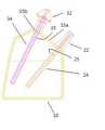
도 1은 본 발명의 제1실시예에 따른 분무 장치의 사시도이고, 도 2는 도 1의 Ⅱ-Ⅱ' 방향 단면도이다. 도 1 및 도 2를 참조하면, 용기부(10)는 약액이 수용되는 공간으로 밀봉, 밀폐 등이 용이하게 단일 몸체로 형성된다. 그로 인해, 용기부(10)를 심하게 흔들거나 눕히더라도 용기부(10) 외부로 약액이 누수되지 않는다.1 is a perspective view of a spray apparatus according to a first embodiment of the present invention, and FIG. 2 is a sectional view taken along line II-II' in FIG. 1. 1 and 2, the
또한, 용기부(10)는 정면에서 이를 바라볼 때, 사용자가 핸드헬드(handheld)하기 용이하도록 소정의 다각형 구조를 갖는다. 이 때, 바닥면은 평평한 표면에 직립 가능하도록 평평하다. 그러나 이와 대조적으로, 바닥면과 대향하는 상부면에는 구강분무부(20)와 비강분무부(30)의 효과적인 배치를 위해 경사면(15)이 형성될 수 있다. 이 때, 경사면(15)은 서로 다른 경사 각도를 갖는 제1경사면(15a)과 제2경사면(15b)으로 구분될 수 있다. 그리고, 경사면(15)에는 구강분무부(20)와 비강분무부(30)가 용기부를 각각 관통하는 연통공이 형성되어 있다.In addition, the
또한, 용기부(10)의 외측면은 사용자의 그립감 향상을 위해 표면 처리될 수 있다. 또한, 용기부(10)의 내측면은 약액의 장기간 보관에 용이하며, 쉽게 변질되지 않도록 코팅 처리될 수 있다.In addition, the outer surface of the
다음으로, 구강분무부(20)는 호흡관(22)과 제1스트로우관(24)이 결합된 조합으로 이루어진다. 호흡관(22)은 일직선 방향으로 연장 형성되는 관으로 내부는 중공되어 사용자의 날숨이나 들숨에 의한 공기가 이동되는 유로가 형성되어 있다. 한편, 호흡관(22)은 그 단부가 사용자의 입 안으로 삽입되면 사용자가 입을 오므려 물기 쉽도록 횡단면적이 점차 감소하는 형상을 갖는다. 이런, 호흡관(22)은 용기부(10)의 어느 일 외측에 용기부(10)의 바닥면과 소정 각도 경사지게 돌출 형성된다. 구체적으로, 호흡관(22)은 용기부(10)의 상부면을 구성하는 일 경사면(15)에 연통공과 연통되는 위치에 부착된다.Next, the
제1스트로우관(24)은 길고 가늘며, 합성수지 계열의 재질로 형성된다. 이 때, 제1스트로우관(24)의 일단은 호흡관(22)과 연통되도록 용기부(10)의 연통공을 관통하여 호흡관(22)의 중공을 따라 삽관되어 고정 결합될 수 있다. 한편, 제1스트로우관(24)의 타측은 용기부(10)의 내부 공간으로 연장된다. 이 때, 타측 타단은 약액 내에 잠긴다. 제1실시예에 따른 제1스트로우관(24)은 호흡관(22)과 나란하게 배치되어 용기부(10)의 바닥면 측 코너를 향한다.The
한편, 제1스트로우관(24)에는 호흡관(22)을 통해 제공되는 사용자의 들숨이나 날숨에 의한 공기가 강제 유출입되게 하는 제1통공(25)이 형성될 수 있다. 제1통공(25)은 제1스트로우관(24)의 어느 일 외주면을 내측으로 비스듬히 커팅하는 방법으로 형성될 수 있다. 이 때, 제1통공(25)은 제1스트로우관(24)의 일단이 호흡관(22)과 연통 결합된 상태에서 용기부(10)의 제1경사면(15a) 내측벽에 근접하도록 형성되는 것이 바람직하다.Meanwhile, a first through
다음으로, 비강분무부(30)는 원추분사관(32)과 제2스트로우관(34)이 결합된 조합으로 이루어진다. 원추분사관(32)은 호흡관(22)과 소정 거리 이격 배치된다. 원추분사관(32)은 내부가 관 형태로 중공되어 약액이나 공기가 이동되는 유로 역할을 한다. 또한, 원추분사관(32)은 일 단부가 사용자의 콧구멍에 삽입 밀착되는 형상을 갖는다. 즉, 원추분사관(32)은 사용자의 콧구멍 크기에 따라 그 삽입되는 정도를 달리할 수 있다.Next, the
제2스트로우관(34)은 제1스트로우관(24)과 동일, 유사한 형상을 갖지만, 설계 변경에 따라 치수 등에 차이가 발생할 수 있다. 제2스트로우관(34)은 일단이 원추분사관(32)과 연통되게 원추분사관(32)의 중공으로 일정 길이만큼 삽관되어 고정 결합된다. 또한, 타측이 용기부(10)의 내부 공간으로 연장되어 타측 타단은 제1스트로우관(24)과 유사하게 용기부(10)의 바닥면 측 코너를 향하게 된다.The
제2스트로우관(34)은 호흡관(22)을 통해 제공되는 사용자의 들숨에 의해 용기부(10) 외부의 공기가 원추분사관(32)을 통해 강제 유입되어 용기부(10) 내의 상측 공간으로 유도되게 한다. 한편, 제2스트로우관(34)에는 호흡관(22)을 통해 제공되는 사용자의 날숨에 의해 용기부(10) 내의 상측 빈 공간에 존재하던 공기가 강제 유입되어 원추분사관(32) 방향으로 유도되게 하는 제2통공(35)이 형성될 수 있다.The
제2통공(35)은 제1통공(25)과 마찬가지로 제2스트로우관(34)의 어느 일 외주면을 내측으로 비스듬히 커팅하는 방법으로 형성될 수 있다. 이 때, 제2통공(35)은 제2스트로우관(34)의 일단이 원추분사관(32)과 연통 결합된 상태에서 용기부(10)의 제2경사면(15b) 내측벽에 근접하도록 형성되는 것이 바람직하다.The second through
이 때, 제1스트로우관(24)과 제2스트로우관(34)은 제1통공(25)과 제2통공(35)이 서로 마주보지 않게 배치되는 것이 바람직하다. 이는 예를 들어, 사용자의 날숨에 의해 제1통공(25)을 거쳐 용기부(10)의 상측 공간으로 유입되는 공기가 제2통공(35)으로 유입되는 공기의 흐름에 즉시 직접적인 영향을 주는 것을 방지한다.At this time, the
[제2실시예][Second Embodiment]
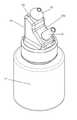
도 3은 본 발명의 제2실시예에 따른 분무 장치의 사시도이고, 도 4는 도 3의 분해 사시도이며, 도 5는 도 3의 정면도이고, 도 6은 도 4의 Ⅵ-Ⅵ' 방향 일부 단면도이다. 도 3 내지 도 6을 참조하면, 제2실시예에 따른 분무 장치는 용기부(10), 구강분무부(20), 비강분무부(30) 등을 포함한다.3 is a perspective view of a spray device according to a second embodiment of the present invention, FIG. 4 is an exploded perspective view of FIG. 3, FIG. 5 is a front view of FIG. 3, and FIG. 6 is a partial cross-sectional view of VI-VI′ in FIG. 4 to be. 3 to 6, the spraying device according to the second embodiment includes a
용기부(10)는 약액이 수용되는 공간을 제공하며 용기본체(12)와 용기캡부(14)를 포함한다. 즉, 용기부(10)는 제1실시예와 달리 상하 분리형으로 이루어진다. 이 때, 분리나 결합은 이미 공지된 다양한 방법 중 어느 하나를 선택하여 적용한다.The
이와 같이, 용기부(10)가 분리형으로 형성되면 약액의 보충이 용이하여 분무 장치를 반영구적으로 사용할 수 있다는 장점을 갖는다. 또한, 제1스트로우관(24)이나 제2스트로우관(34)을 쉽게 교체할 수 있어 유지 관리 등이 편리하다.As described above, when the
용기본체(12)는 유리나 합성수지 등의 소재로 만들어진다. 이 때, 용기본체(12)의 상면에는 약액이 공급되는 투입구(13)가 형성될 수 있다. 이런 투입구(13)는 용기본체(12)의 상면에서 연직 상방으로 연장되는 원통체결면의 개구일 수 있다.The
용기캡부(14)는 크게 하측부와 상측부로 구분될 수 있고, 하측부는 용기본체(12)와 밀폐되도록 결합된다. 이를 위해, 원통체결면의 외주면에는 예를 들어, 숫나사산이 형성되고, 이에 대응되어 용기캡부(14)의 하측부 내주면에는 암나사산이 형성된다. 또한, 용기캡부(14)의 상측부 상단에는 구강분무부(20)와 비강분무부(30)가 각각 배치되는 경사면(15)이 형성될 수 있다. 이런, 경사면(15)은 경사 각도를 서로 달리하는 제1경사면(15a), 제2경사면(15b) 및 제1경사면(15a)과 제2경사면(15b) 사이의 단차를 제거하여 이들을 서로 연결시키는 연결경사면(15c)을 포함할 수 있다.The
다음으로, 구강분무부(20)는 호흡관(22)과 제1스트로우관(24)의 조합으로 구성된다. 호흡관(22)과 제1스트로우관(24)에 대해서는 제1실시예에서 이미 상술한 바, 동일하게 반복되는 설명에 대해서는 이하 생략한다. 제2실시예에서, 구강분무부(20)는 제1스트로우관(24)의 일단이 호흡관(22)과 연통되는 방식에서 제1실시예와 다소 차이가 있다.Next, the
이를 위해, 용기캡부(14)의 경사면(15) 내측면에는 제1스트로우관(24)이 끼움 결합되게 하는 끼움홈돌부(16)가 형성될 수 있다. 이런 끼움홈돌부(16)는 제1경사면(15a)의 내측면에 연직 하방으로 연장 형성될 수 있다. 그로 인해, 끼움홈돌부(16)에 결합되는 제1스트로우관(24)은 용기본체(12)의 바닥면과 수직하게 배치된다. 따라서, 호흡관(22)과 제1스트로우관(24)을 연결하는 부위에서 유로는 절곡되어 그 흐름 방향이 달라진다. 이 때, 호흡관(22)과 제1스트로우관(24)를 연결하는 부위에는 소정의 연결공간(17)이 형성될 수 있다.To this end, a
마찬가지로, 용기캡부(14)의 경사면(15) 내측면에는 제2스트로우관(34)이 끼움 결합되게 하는 끼움홈돌부(16)가 형성될 수 있다. 그 결과, 원추분사관(32)과 제2스트로우관(34)을 연결하는 부위에서 유로는 절곡되어 그 흐름 방향이 달라진다. 마찬가지로, 원추분사관(32)과 제2스트로우관(34)를 연결하는 부위에는 소정의 연결공간(17)이 형성될 수 있다.Likewise, a
이 때, 제1스트로우관(24)과 제2스트로우관(34)은 제1통공(25)과 제2통공(35)이 서로 마주보지 않게 배치되는 것이 바람직하다. 동시에, 제1통공(25)과 제2통공(35)은 제1스트로우관(24)과 제2스트로우관(34)이 끼움홈돌부(16)에 각각 끼움 결합된 상태에서 단차가 발생하도록 그 높이를 달리할 수 있다. 이는 예를 들어, 사용자의 날숨에 의해 제1통공(25)을 거쳐 용기부의 상측 공간으로 유입되는 공기가 제2통공(35)으로 유입되는 공기의 흐름에 바로 직접적인 영향을 미치는 것을 방지한다.At this time, the
또한, 제1스트로우관(24)과 제2스트로우관(34)의 타측 단부는 용기본체(12)의 바닥면에서 동일 높이를 갖는 것이 바람직하다.In addition, it is preferable that the other end portions of the
[제3실시예][Example 3]
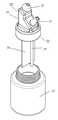
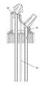
도 7은 본 발명의 제3실시예에 따른 분무 장치의 사시도이고, 도 8은 도 8의 분해 사시도이며, 도 9는 도 8의 Ⅸ-Ⅸ' 방향 일부 단면도이다.7 is a perspective view of a spray device according to a third embodiment of the present invention, FIG. 8 is an exploded perspective view of FIG. 8, and FIG. 9 is a partial cross-sectional view taken along the line ′-′ in FIG. 8.
제3실시예는 제2실시예와 전체적으로 동일하되, 용기캡부(14)에 격벽(18)이 더 추가되어 있을 뿐이다. 이런 격벽(18)은 예를 들어, 용기캡부(14)의 상측부 상단을 구성하는 연결경사면(15c)의 내측면에서 연직 하방으로 연장 형성되는 플레이트 형상일 수 있다. 이 때, 격벽(18)은 제1스트로우관(24) 및 제2스트로우관(34) 사이 공간을 가로지를 수 있다. 그 결과, 공기는 격벽(18)에 의해 차단되어 제1통공(25)과 제2통공(35) 사이를 바로 직접 흐를 수 없게 된다.The third embodiment is the same as the second embodiment as a whole, but only the
이 때, 격벽(18)은 용기본체(12)의 바닥면을 기준으로 제1스트로우관(24) 및 제2스트로우관(34)과 동일 높이를 갖도록 형성된다. 그로 인해, 사용자의 날숨이나 들숨에 의한 영향은 격벽(18)에 의해 차단되어 약액이 제1스트로우관(24)과 제2스트로우관(34) 사이에서 직접 흐르는 것을 방지한다.At this time, the
이상 살펴 본 것처럼, 제1실시예 내지 제3실시예에 따른 분무 장치는 사용자가 구강 내 도포를 위해 들숨을 들이쉬고, 비강 내 도포를 위해 날숨을 내쉬면 약액이 분무 형태로 각 부위에 넓게 도포된다는 효과를 제공한다. 즉, 종래와 차별화되는 간단한 구조를 통해 가격 경쟁력과 생산성을 보다 향상시킬 수 있다.As described above, in the spraying devices according to the first to third embodiments, when the user inhales for intraoral application and exhales for intranasal application, the chemical solution is widely applied to each site in the form of a spray. It provides an effect. In other words, it is possible to further improve price competitiveness and productivity through a simple structure different from the conventional one.
이하, 전술한 제1실시예 내지 제3실시예에 따른 분무 장치의 사용 방법을 설명한다. 도 10은 비강 내 도포를 위한 분무 장치의 사용 개념도이고, 도 11은 구강 내 도포를 위한 분무 장치의 사용 개념도이다.Hereinafter, a method of using the spray device according to the first to third embodiments described above will be described. 10 is a conceptual diagram of the use of a spray device for intranasal application, and FIG. 11 is a conceptual view of the use of a spray device for intraoral application.
먼저, 비강 내 도포법을 살펴본다. 도 10을 참조하면, 사용자는 비강분무부(30)의 단부 즉, 원추분사관(32)이 콧구멍에 밀착되도록 삽입하고, 구강분무부(20)의 단부 즉, 호흡관(22)을 입 안으로 삽입하여 문다. 그 상태에서 사용자는 날숨을 내쉬어 입 안에서 배출되는 공기를 호흡관(22)을 통해 용기부(10) 측으로 불어 넣는다. 이 때, 날숨의 대부분은 호흡관(22), 제1스트로우관(24)의 타측 단부를 거쳐 토출되어 용기부(10) 내에 수용된 약액이 제2스트로우관(34)으로 유입되어 원추분사관(32)을 통해 유출되도록 한다. 한편, 날숨의 나머지는 제1통공(25)을 통해 용기부(10) 상측 내부 빈 공간으로 배출되고, 이는 제2통공(35)을 통해 공기가 제2스트로우관(34)으로 유입되도록 한다.First, we will look at how to apply in the nasal cavity. Referring to FIG. 10, the user inserts the end portion of the
그 결과, 제2스트로우관(34)을 통해 이송되는 약액은 제2통공(35)으로 유입되는 공기와 혼합되고, 원추분사관(32)으로 이동하게 된다. 이 때, 원추분사관(32)을 통해 비강으로 분출되는 혼합액은 내외부의 압력의 차이 등으로 인해 넓게 분무된다.As a result, the chemical liquid transferred through the
다음, 구강 내 도포법을 살펴본다. 도 10을 참조하면, 사용자는 구강분무부(20)의 단부 즉, 호흡관(22)을 입 안으로 삽입하여 문다. 그 상태에서 사용자는 들숨을 내쉬어 입 안으로 공기를 들이 마쉰다. 마쉬는 순간, 약액은 입 안으로 분무된다. 이는 사용자의 들숨에 의해 약액이 제1스트로우관(24)을 통해 유입됨과 동시에 용기부(10)의 외부 공기 또한 원추분사관(32)을 통해 유입되고 제2통공(35)을 통해 용기부(10)의 상측 내부 공간으로 토출됨에 따라 용기부(10)의 상측 빈 공간의 공기 중 일부가 제1통공(25)을 통해 제1스트로우관(24)으로 유입되어 약액과 혼합되는 현상에 기인한다. 이 때, 호흡관(22)을 통해 구강으로 분출되는 혼합액은 내외부의 압력의 차이 등으로 인해 넓게 분무된다.Next, look at the intraoral application method. Referring to FIG. 10, the user inserts the bite of the
이상에서는 본 발명의 바람직한 실시예를 예시적으로 설명하였으나, 본 발명의 범위는 이와 같은 특정 실시예에만 한정되는 것은 아니며, 특허청구범위에 기재된 범주 내에서 적절하게 변경 가능한 것이다.The preferred embodiments of the present invention have been exemplarily described above, but the scope of the present invention is not limited to such specific embodiments, and can be appropriately changed within the scope described in the claims.
10: 용기부20: 구강분무부
30: 비강분무부22: 호흡관
24: 제1스트로우관32: 원추분사관
34: 제2스트로우관12: 용기본체
13: 투입구14: 용기캡부
15: 경사면16: 끼움홈돌부
18: 격벽10: container portion 20: oral spray unit
30: nasal spray 22: respiratory tract
24: First Straw tube 32: Cone spray tube
34: second straw tube 12: container body
13: Inlet 14: Container cap portion
15: slope 16: fitting groove protrusion
18: bulkhead
Claims (7)
Translated fromKorean사용자의 들숨에 의해 약액이 흡입되어 사용자의 구강으로 분무되는 구강분무부; 및
상기 구강분무부에서 이격 배치되며, 사용자가 상기 구강분무부를 통해 날숨을 제공하면 약액이 사용자의 비강으로 분무되는 비강분무부;를 포함하며,
상기 구강분무부는
단부가 사용자의 입 안으로 삽입되도록 상기 용기부의 어느 일 외측에 상기 용기부의 바닥면과 소정 각도 경사지게 돌출 형성되는 호흡관; 및
일단이 상기 호흡관과 연통되고, 타측이 상기 용기부의 내부 공간으로 연장되며, 상기 호흡관을 통해 제공되는 사용자의 들숨이나 날숨에 의한 공기가 강제 유출입되게 하는 제1통공이 형성되는 제1스트로우관;를 포함하는 구강 및 비강 내에 약액을 도포하기 위한 분무 장치.
A container portion in which the chemical solution is accommodated;
An oral spray unit which is inhaled by the user's breath and sprayed into the user's mouth; And
It includes a nasal spray unit that is spaced apart from the oral spray unit, and when the user provides exhalation through the oral spray unit, the chemical solution is sprayed into the user's nasal cavity.
The oral spray unit
A breathing tube formed to protrude at a predetermined angle from the bottom surface of the container part on one outside of the container part so that the end is inserted into the user's mouth; And
A first strobe tube having one end communicating with the breathing tube, the other side extending into the inner space of the container part, and a first through hole through which a user inhales or exhales air through the breathing tube is forced to flow in and out. Spraying device for applying a chemical solution in the oral cavity and nasal cavity containing a.
상기 호흡관과 이격 배치되며, 일 단부가 사용자의 콧구멍에 삽입 밀착되는 형상의 원추분사관; 및
일단이 상기 원추분사관과 연통되고, 타측이 상기 용기부의 내부 공간으로 연장되며, 상기 호흡관을 통해 제공되는 사용자의 들숨에 의해 상기 용기부 외부의 공기가 상기 원추분사관을 통해 강제 유입되어 상기 용기부 내의 상측 공간으로 유도되게 하고, 상기 호흡관을 통해 제공되는 사용자의 날숨에 의해 상기 용기부 내의 상측 공간에 존재하던 공기가 강제 유입되어 상기 원추분사관 방향으로 유도되게 하는 제2통공이 형성되는 제2스트로우관;를 포함하는 구강 및 비강 내에 약액을 도포하기 위한 분무 장치.
According to claim 1, The nasal spray unit
A conical injection tube disposed spaced apart from the breathing tube and having one end inserted into the nostril of the user in close contact; And
One end is in communication with the cone injection pipe, the other side extends into the inner space of the container portion, and the air outside the container portion is forcedly introduced through the cone injection pipe by the inhalation of a user provided through the breathing pipe. A second through hole is formed to be guided to the upper space in the container part, and the air existing in the upper space in the container part is forcedly introduced by the user's exhalation provided through the breathing tube and directed to the cone injection tube. Spraying device for applying a chemical liquid in the oral cavity and nasal cavity, including; a second straw tube.
상면에 약액이 공급되는 투입구가 형성되는 용기본체; 및
하측부가 상기 용기본체와 밀폐 결합되고, 상측부 상단에는 상기 구강분무부와 상기 비강분무부가 각각 배치되도록 서로 각도를 달리하는 경사면이 형성되는 용기캡부;를 포함하는 구강 및 비강 내에 약액을 도포하기 위한 분무 장치.
According to claim 3, The container portion
A container body on which an inlet through which a chemical solution is supplied is formed; And
The lower portion is hermetically coupled with the container body, the upper portion of the upper portion of the oral spray portion and the nasal spray portion is formed on each other so that the inclined surface is formed with an inclined surface that is different from each other; containing oral and nasal cavity for applying the chemicals Spraying device.
상기 경사면의 내측면에는 상기 제1스트로우관 및 상기 제2스트로우관이 각각 끼움 결합되게 하는 끼움홈돌부가 형성되는 구강 및 비강 내에 약액을 도포하기 위한 분무 장치.
According to claim 4,
A spraying device for applying a chemical solution in the oral cavity and the nasal cavity in which the first groove and the second groove are formed on the inner surface of the inclined surface so that the first groove and the second groove are respectively fitted.
상기 제1스트로우관과 상기 제2스트로우관은 상기 제1통공과 상기 제2통공이 서로 마주보지 않게 배치되는 구강 및 비강 내에 약액을 도포하기 위한 분무 장치.
According to claim 4,
A spraying device for applying a chemical solution to the oral cavity and nasal cavity in which the first through-hole and the second through-hole are disposed so that the first through-hole and the second through-hole do not face each other.
상기 경사면의 내측면에는 상기 제1스트로우관 및 상기 제2스트로우관 사이 공간을 가로지르는 격벽;이 더 형성되는 구강 및 비강 내에 약액을 도포하기 위한 분무 장치.According to claim 4,
The inner surface of the inclined surface, the partition wall that traverses the space between the first and second straw tubes; Spraying device for applying a chemical solution in the oral cavity and nasal cavity is further formed.
Priority Applications (1)
| Application Number | Priority Date | Filing Date | Title |
|---|---|---|---|
| KR1020180045519AKR102138725B1 (en) | 2018-04-19 | 2018-04-19 | Upper airway spraying device for coating chemical liquid into oral cavity and nasal cavity |
Applications Claiming Priority (1)
| Application Number | Priority Date | Filing Date | Title |
|---|---|---|---|
| KR1020180045519AKR102138725B1 (en) | 2018-04-19 | 2018-04-19 | Upper airway spraying device for coating chemical liquid into oral cavity and nasal cavity |
Publications (2)
| Publication Number | Publication Date |
|---|---|
| KR20190121974A KR20190121974A (en) | 2019-10-29 |
| KR102138725B1true KR102138725B1 (en) | 2020-07-28 |
Family
ID=68423987
Family Applications (1)
| Application Number | Title | Priority Date | Filing Date |
|---|---|---|---|
| KR1020180045519AActiveKR102138725B1 (en) | 2018-04-19 | 2018-04-19 | Upper airway spraying device for coating chemical liquid into oral cavity and nasal cavity |
Country Status (1)
| Country | Link |
|---|---|
| KR (1) | KR102138725B1 (en) |
Cited By (1)
| Publication number | Priority date | Publication date | Assignee | Title |
|---|---|---|---|---|
| RU229732U1 (en)* | 2024-05-13 | 2024-10-24 | Владимир Викторович Михайлов | MOBILE AUTONOMOUS INHALER-VAPORATOR |
Families Citing this family (1)
| Publication number | Priority date | Publication date | Assignee | Title |
|---|---|---|---|---|
| US11701479B1 (en)* | 2022-02-01 | 2023-07-18 | Green Sky Creations LLC | Systems, devices, and methods for administering cannabinoid mixtures |
Citations (4)
| Publication number | Priority date | Publication date | Assignee | Title |
|---|---|---|---|---|
| US20130180524A1 (en)* | 2010-09-02 | 2013-07-18 | Sipnose Ltd. | Nasal delivary device |
| KR101324023B1 (en) | 2004-09-15 | 2013-11-01 | 옵티노즈 에이에스 | Nasal delivery devices |
| KR101547502B1 (en)* | 2007-10-03 | 2015-08-26 | 옵티노즈 에이에스 | Nasal delivery devices |
| JP6264368B2 (en) | 2012-04-20 | 2018-01-24 | ヨンウー カンパニー,リミテッド | Nasal rinse water spray container |
Family Cites Families (5)
| Publication number | Priority date | Publication date | Assignee | Title |
|---|---|---|---|---|
| US20060289006A1 (en)* | 2005-06-27 | 2006-12-28 | Kos Life Sciences, Inc. | Breath actuated nasal drug delivery system |
| US8048023B2 (en) | 2007-03-06 | 2011-11-01 | Rhinosystems Inc. | Systems and methods for nasal irrigation |
| KR101246845B1 (en) | 2011-03-18 | 2013-03-25 | 박지용 | Container for nasal cavity |
| KR20120106376A (en) | 2011-03-18 | 2012-09-26 | 박지용 | Container for nasal cavity |
| KR101782548B1 (en) | 2017-08-07 | 2017-09-27 | 임금빈 | Nasal wash container |
- 2018
- 2018-04-19KRKR1020180045519Apatent/KR102138725B1/enactiveActive
Patent Citations (4)
| Publication number | Priority date | Publication date | Assignee | Title |
|---|---|---|---|---|
| KR101324023B1 (en) | 2004-09-15 | 2013-11-01 | 옵티노즈 에이에스 | Nasal delivery devices |
| KR101547502B1 (en)* | 2007-10-03 | 2015-08-26 | 옵티노즈 에이에스 | Nasal delivery devices |
| US20130180524A1 (en)* | 2010-09-02 | 2013-07-18 | Sipnose Ltd. | Nasal delivary device |
| JP6264368B2 (en) | 2012-04-20 | 2018-01-24 | ヨンウー カンパニー,リミテッド | Nasal rinse water spray container |
Cited By (1)
| Publication number | Priority date | Publication date | Assignee | Title |
|---|---|---|---|---|
| RU229732U1 (en)* | 2024-05-13 | 2024-10-24 | Владимир Викторович Михайлов | MOBILE AUTONOMOUS INHALER-VAPORATOR |
Also Published As
| Publication number | Publication date |
|---|---|
| KR20190121974A (en) | 2019-10-29 |
Similar Documents
| Publication | Publication Date | Title |
|---|---|---|
| US7191776B2 (en) | Nebulizer breathing system | |
| US3097645A (en) | Nebulizer | |
| US5435297A (en) | Medical device for inhaling metered aerosols | |
| JP5118290B2 (en) | Nebulizer with auxiliary inlet port | |
| EP0957960B1 (en) | Breathing circuit apparatus for a nebulizer | |
| US7047968B2 (en) | Device for generating a continuous positive airway pressure (CPAP device) | |
| US4512341A (en) | Nebulizer with capillary feed | |
| US5906198A (en) | Nasal nebulizer | |
| US3353536A (en) | Nebulizer | |
| US10137260B2 (en) | Nebulizer kit and nebulizer | |
| US2266706A (en) | Nasal atomizing inhaler and dropper | |
| US7971761B1 (en) | Apparatus and method for nasal passage rinse | |
| US20170007788A1 (en) | Actuator and Nose Piece for a Nasal Inhaler | |
| US10576221B2 (en) | Internal nebulizer seal and method of use | |
| KR102138725B1 (en) | Upper airway spraying device for coating chemical liquid into oral cavity and nasal cavity | |
| US20110108022A1 (en) | Nebulizer device | |
| CN110354350A (en) | A kind of atomizer of improvement | |
| ITBS20030075U1 (en) | NEBULIZING NEEDLE WITH BLAST CHILLER PARTICLES ABUSTER | |
| WO2007068341A1 (en) | A mask for aerosol therapy | |
| KR20200098188A (en) | Multi functional upper airway spraying device | |
| CN211611148U (en) | Atomization inhalation device capable of preventing liquid medicine from flowing out | |
| KR101897152B1 (en) | Nebulizer | |
| US11998684B2 (en) | Dosing system for a nebulizer | |
| USRE6260E (en) | Improvement in combined inhalers and nasal douches | |
| KR20240041082A (en) | Chemical liquid cartridge and portable chemical liquid aerosol inhaler |
Legal Events
| Date | Code | Title | Description |
|---|---|---|---|
| A201 | Request for examination | ||
| PA0109 | Patent application | St.27 status event code:A-0-1-A10-A12-nap-PA0109 | |
| PA0201 | Request for examination | St.27 status event code:A-1-2-D10-D11-exm-PA0201 | |
| P11-X000 | Amendment of application requested | St.27 status event code:A-2-2-P10-P11-nap-X000 | |
| P13-X000 | Application amended | St.27 status event code:A-2-2-P10-P13-nap-X000 | |
| D13-X000 | Search requested | St.27 status event code:A-1-2-D10-D13-srh-X000 | |
| D14-X000 | Search report completed | St.27 status event code:A-1-2-D10-D14-srh-X000 | |
| R18-X000 | Changes to party contact information recorded | St.27 status event code:A-3-3-R10-R18-oth-X000 | |
| E902 | Notification of reason for refusal | ||
| PE0902 | Notice of grounds for rejection | St.27 status event code:A-1-2-D10-D21-exm-PE0902 | |
| PG1501 | Laying open of application | St.27 status event code:A-1-1-Q10-Q12-nap-PG1501 | |
| E13-X000 | Pre-grant limitation requested | St.27 status event code:A-2-3-E10-E13-lim-X000 | |
| P11-X000 | Amendment of application requested | St.27 status event code:A-2-2-P10-P11-nap-X000 | |
| P13-X000 | Application amended | St.27 status event code:A-2-2-P10-P13-nap-X000 | |
| E701 | Decision to grant or registration of patent right | ||
| PE0701 | Decision of registration | St.27 status event code:A-1-2-D10-D22-exm-PE0701 | |
| GRNT | Written decision to grant | ||
| PR0701 | Registration of establishment | St.27 status event code:A-2-4-F10-F11-exm-PR0701 | |
| PR1002 | Payment of registration fee | St.27 status event code:A-2-2-U10-U11-oth-PR1002 Fee payment year number:1 | |
| PG1601 | Publication of registration | St.27 status event code:A-4-4-Q10-Q13-nap-PG1601 | |
| PR1001 | Payment of annual fee | St.27 status event code:A-4-4-U10-U11-oth-PR1001 Fee payment year number:4 | |
| PR1001 | Payment of annual fee | St.27 status event code:A-4-4-U10-U11-oth-PR1001 Fee payment year number:5 | |
| PR1001 | Payment of annual fee | St.27 status event code:A-4-4-U10-U11-oth-PR1001 Fee payment year number:6 |