KR102137726B1 - Production method for rare earth permanent magnet - Google Patents
Production method for rare earth permanent magnetDownload PDFInfo
- Publication number
- KR102137726B1 KR102137726B1KR1020157008010AKR20157008010AKR102137726B1KR 102137726 B1KR102137726 B1KR 102137726B1KR 1020157008010 AKR1020157008010 AKR 1020157008010AKR 20157008010 AKR20157008010 AKR 20157008010AKR 102137726 B1KR102137726 B1KR 102137726B1
- Authority
- KR
- South Korea
- Prior art keywords
- rare earth
- magnet body
- oxide
- sintered magnet
- powder
- Prior art date
- Legal status (The legal status is an assumption and is not a legal conclusion. Google has not performed a legal analysis and makes no representation as to the accuracy of the status listed.)
- Active
Links
Images
Classifications
- H—ELECTRICITY
- H01—ELECTRIC ELEMENTS
- H01F—MAGNETS; INDUCTANCES; TRANSFORMERS; SELECTION OF MATERIALS FOR THEIR MAGNETIC PROPERTIES
- H01F41/00—Apparatus or processes specially adapted for manufacturing or assembling magnets, inductances or transformers; Apparatus or processes specially adapted for manufacturing materials characterised by their magnetic properties
- H01F41/02—Apparatus or processes specially adapted for manufacturing or assembling magnets, inductances or transformers; Apparatus or processes specially adapted for manufacturing materials characterised by their magnetic properties for manufacturing cores, coils, or magnets
- C—CHEMISTRY; METALLURGY
- C25—ELECTROLYTIC OR ELECTROPHORETIC PROCESSES; APPARATUS THEREFOR
- C25D—PROCESSES FOR THE ELECTROLYTIC OR ELECTROPHORETIC PRODUCTION OF COATINGS; ELECTROFORMING; APPARATUS THEREFOR
- C25D7/00—Electroplating characterised by the article coated
- C25D7/001—Magnets
- B—PERFORMING OPERATIONS; TRANSPORTING
- B22—CASTING; POWDER METALLURGY
- B22F—WORKING METALLIC POWDER; MANUFACTURE OF ARTICLES FROM METALLIC POWDER; MAKING METALLIC POWDER; APPARATUS OR DEVICES SPECIALLY ADAPTED FOR METALLIC POWDER
- B22F3/00—Manufacture of workpieces or articles from metallic powder characterised by the manner of compacting or sintering; Apparatus specially adapted therefor ; Presses and furnaces
- B22F3/24—After-treatment of workpieces or articles
- C—CHEMISTRY; METALLURGY
- C21—METALLURGY OF IRON
- C21D—MODIFYING THE PHYSICAL STRUCTURE OF FERROUS METALS; GENERAL DEVICES FOR HEAT TREATMENT OF FERROUS OR NON-FERROUS METALS OR ALLOYS; MAKING METAL MALLEABLE, e.g. BY DECARBURISATION OR TEMPERING
- C21D1/00—General methods or devices for heat treatment, e.g. annealing, hardening, quenching or tempering
- C21D1/26—Methods of annealing
- C21D1/28—Normalising
- C—CHEMISTRY; METALLURGY
- C22—METALLURGY; FERROUS OR NON-FERROUS ALLOYS; TREATMENT OF ALLOYS OR NON-FERROUS METALS
- C22C—ALLOYS
- C22C38/00—Ferrous alloys, e.g. steel alloys
- C—CHEMISTRY; METALLURGY
- C22—METALLURGY; FERROUS OR NON-FERROUS ALLOYS; TREATMENT OF ALLOYS OR NON-FERROUS METALS
- C22C—ALLOYS
- C22C38/00—Ferrous alloys, e.g. steel alloys
- C22C38/002—Ferrous alloys, e.g. steel alloys containing In, Mg, or other elements not provided for in one single group C22C38/001 - C22C38/60
- C—CHEMISTRY; METALLURGY
- C22—METALLURGY; FERROUS OR NON-FERROUS ALLOYS; TREATMENT OF ALLOYS OR NON-FERROUS METALS
- C22C—ALLOYS
- C22C38/00—Ferrous alloys, e.g. steel alloys
- C22C38/005—Ferrous alloys, e.g. steel alloys containing rare earths, i.e. Sc, Y, Lanthanides
- C—CHEMISTRY; METALLURGY
- C22—METALLURGY; FERROUS OR NON-FERROUS ALLOYS; TREATMENT OF ALLOYS OR NON-FERROUS METALS
- C22C—ALLOYS
- C22C38/00—Ferrous alloys, e.g. steel alloys
- C22C38/02—Ferrous alloys, e.g. steel alloys containing silicon
- C—CHEMISTRY; METALLURGY
- C22—METALLURGY; FERROUS OR NON-FERROUS ALLOYS; TREATMENT OF ALLOYS OR NON-FERROUS METALS
- C22C—ALLOYS
- C22C38/00—Ferrous alloys, e.g. steel alloys
- C22C38/06—Ferrous alloys, e.g. steel alloys containing aluminium
- C—CHEMISTRY; METALLURGY
- C22—METALLURGY; FERROUS OR NON-FERROUS ALLOYS; TREATMENT OF ALLOYS OR NON-FERROUS METALS
- C22C—ALLOYS
- C22C38/00—Ferrous alloys, e.g. steel alloys
- C22C38/14—Ferrous alloys, e.g. steel alloys containing titanium or zirconium
- C—CHEMISTRY; METALLURGY
- C25—ELECTROLYTIC OR ELECTROPHORETIC PROCESSES; APPARATUS THEREFOR
- C25D—PROCESSES FOR THE ELECTROLYTIC OR ELECTROPHORETIC PRODUCTION OF COATINGS; ELECTROFORMING; APPARATUS THEREFOR
- C25D3/00—Electroplating: Baths therefor
- C25D3/02—Electroplating: Baths therefor from solutions
- C25D3/56—Electroplating: Baths therefor from solutions of alloys
- C25D3/562—Electroplating: Baths therefor from solutions of alloys containing more than 50% by weight of iron or nickel or cobalt
- H—ELECTRICITY
- H01—ELECTRIC ELEMENTS
- H01F—MAGNETS; INDUCTANCES; TRANSFORMERS; SELECTION OF MATERIALS FOR THEIR MAGNETIC PROPERTIES
- H01F1/00—Magnets or magnetic bodies characterised by the magnetic materials therefor; Selection of materials for their magnetic properties
- H01F1/01—Magnets or magnetic bodies characterised by the magnetic materials therefor; Selection of materials for their magnetic properties of inorganic materials
- H01F1/03—Magnets or magnetic bodies characterised by the magnetic materials therefor; Selection of materials for their magnetic properties of inorganic materials characterised by their coercivity
- H01F1/032—Magnets or magnetic bodies characterised by the magnetic materials therefor; Selection of materials for their magnetic properties of inorganic materials characterised by their coercivity of hard-magnetic materials
- H01F1/04—Magnets or magnetic bodies characterised by the magnetic materials therefor; Selection of materials for their magnetic properties of inorganic materials characterised by their coercivity of hard-magnetic materials metals or alloys
- H01F1/047—Alloys characterised by their composition
- H01F1/053—Alloys characterised by their composition containing rare earth metals
- H01F1/0536—Alloys characterised by their composition containing rare earth metals sintered
- H—ELECTRICITY
- H01—ELECTRIC ELEMENTS
- H01F—MAGNETS; INDUCTANCES; TRANSFORMERS; SELECTION OF MATERIALS FOR THEIR MAGNETIC PROPERTIES
- H01F1/00—Magnets or magnetic bodies characterised by the magnetic materials therefor; Selection of materials for their magnetic properties
- H01F1/01—Magnets or magnetic bodies characterised by the magnetic materials therefor; Selection of materials for their magnetic properties of inorganic materials
- H01F1/03—Magnets or magnetic bodies characterised by the magnetic materials therefor; Selection of materials for their magnetic properties of inorganic materials characterised by their coercivity
- H01F1/032—Magnets or magnetic bodies characterised by the magnetic materials therefor; Selection of materials for their magnetic properties of inorganic materials characterised by their coercivity of hard-magnetic materials
- H01F1/04—Magnets or magnetic bodies characterised by the magnetic materials therefor; Selection of materials for their magnetic properties of inorganic materials characterised by their coercivity of hard-magnetic materials metals or alloys
- H01F1/047—Alloys characterised by their composition
- H01F1/053—Alloys characterised by their composition containing rare earth metals
- H01F1/055—Alloys characterised by their composition containing rare earth metals and magnetic transition metals, e.g. SmCo5
- H01F1/057—Alloys characterised by their composition containing rare earth metals and magnetic transition metals, e.g. SmCo5 and IIIa elements, e.g. Nd2Fe14B
- H—ELECTRICITY
- H01—ELECTRIC ELEMENTS
- H01F—MAGNETS; INDUCTANCES; TRANSFORMERS; SELECTION OF MATERIALS FOR THEIR MAGNETIC PROPERTIES
- H01F1/00—Magnets or magnetic bodies characterised by the magnetic materials therefor; Selection of materials for their magnetic properties
- H01F1/01—Magnets or magnetic bodies characterised by the magnetic materials therefor; Selection of materials for their magnetic properties of inorganic materials
- H01F1/03—Magnets or magnetic bodies characterised by the magnetic materials therefor; Selection of materials for their magnetic properties of inorganic materials characterised by their coercivity
- H01F1/032—Magnets or magnetic bodies characterised by the magnetic materials therefor; Selection of materials for their magnetic properties of inorganic materials characterised by their coercivity of hard-magnetic materials
- H01F1/04—Magnets or magnetic bodies characterised by the magnetic materials therefor; Selection of materials for their magnetic properties of inorganic materials characterised by their coercivity of hard-magnetic materials metals or alloys
- H01F1/06—Magnets or magnetic bodies characterised by the magnetic materials therefor; Selection of materials for their magnetic properties of inorganic materials characterised by their coercivity of hard-magnetic materials metals or alloys in the form of particles, e.g. powder
- H01F1/08—Magnets or magnetic bodies characterised by the magnetic materials therefor; Selection of materials for their magnetic properties of inorganic materials characterised by their coercivity of hard-magnetic materials metals or alloys in the form of particles, e.g. powder pressed, sintered, or bound together
- H—ELECTRICITY
- H01—ELECTRIC ELEMENTS
- H01F—MAGNETS; INDUCTANCES; TRANSFORMERS; SELECTION OF MATERIALS FOR THEIR MAGNETIC PROPERTIES
- H01F41/00—Apparatus or processes specially adapted for manufacturing or assembling magnets, inductances or transformers; Apparatus or processes specially adapted for manufacturing materials characterised by their magnetic properties
- H01F41/02—Apparatus or processes specially adapted for manufacturing or assembling magnets, inductances or transformers; Apparatus or processes specially adapted for manufacturing materials characterised by their magnetic properties for manufacturing cores, coils, or magnets
- H01F41/0253—Apparatus or processes specially adapted for manufacturing or assembling magnets, inductances or transformers; Apparatus or processes specially adapted for manufacturing materials characterised by their magnetic properties for manufacturing cores, coils, or magnets for manufacturing permanent magnets
- H01F41/0293—Apparatus or processes specially adapted for manufacturing or assembling magnets, inductances or transformers; Apparatus or processes specially adapted for manufacturing materials characterised by their magnetic properties for manufacturing cores, coils, or magnets for manufacturing permanent magnets diffusion of rare earth elements, e.g. Tb, Dy or Ho, into permanent magnets
- B—PERFORMING OPERATIONS; TRANSPORTING
- B22—CASTING; POWDER METALLURGY
- B22F—WORKING METALLIC POWDER; MANUFACTURE OF ARTICLES FROM METALLIC POWDER; MAKING METALLIC POWDER; APPARATUS OR DEVICES SPECIALLY ADAPTED FOR METALLIC POWDER
- B22F3/00—Manufacture of workpieces or articles from metallic powder characterised by the manner of compacting or sintering; Apparatus specially adapted therefor ; Presses and furnaces
- B22F3/24—After-treatment of workpieces or articles
- B22F2003/241—Chemical after-treatment on the surface
- B22F2003/242—Coating
- B—PERFORMING OPERATIONS; TRANSPORTING
- B22—CASTING; POWDER METALLURGY
- B22F—WORKING METALLIC POWDER; MANUFACTURE OF ARTICLES FROM METALLIC POWDER; MAKING METALLIC POWDER; APPARATUS OR DEVICES SPECIALLY ADAPTED FOR METALLIC POWDER
- B22F3/00—Manufacture of workpieces or articles from metallic powder characterised by the manner of compacting or sintering; Apparatus specially adapted therefor ; Presses and furnaces
- B22F3/24—After-treatment of workpieces or articles
- B22F2003/248—Thermal after-treatment
- H—ELECTRICITY
- H01—ELECTRIC ELEMENTS
- H01F—MAGNETS; INDUCTANCES; TRANSFORMERS; SELECTION OF MATERIALS FOR THEIR MAGNETIC PROPERTIES
- H01F1/00—Magnets or magnetic bodies characterised by the magnetic materials therefor; Selection of materials for their magnetic properties
- H01F1/01—Magnets or magnetic bodies characterised by the magnetic materials therefor; Selection of materials for their magnetic properties of inorganic materials
- H01F1/03—Magnets or magnetic bodies characterised by the magnetic materials therefor; Selection of materials for their magnetic properties of inorganic materials characterised by their coercivity
- H01F1/032—Magnets or magnetic bodies characterised by the magnetic materials therefor; Selection of materials for their magnetic properties of inorganic materials characterised by their coercivity of hard-magnetic materials
- H01F1/04—Magnets or magnetic bodies characterised by the magnetic materials therefor; Selection of materials for their magnetic properties of inorganic materials characterised by their coercivity of hard-magnetic materials metals or alloys
- H01F1/047—Alloys characterised by their composition
- H01F1/053—Alloys characterised by their composition containing rare earth metals
- H01F1/055—Alloys characterised by their composition containing rare earth metals and magnetic transition metals, e.g. SmCo5
- H01F1/057—Alloys characterised by their composition containing rare earth metals and magnetic transition metals, e.g. SmCo5 and IIIa elements, e.g. Nd2Fe14B
- H01F1/0571—Alloys characterised by their composition containing rare earth metals and magnetic transition metals, e.g. SmCo5 and IIIa elements, e.g. Nd2Fe14B in the form of particles, e.g. rapid quenched powders or ribbon flakes
- H01F1/0575—Alloys characterised by their composition containing rare earth metals and magnetic transition metals, e.g. SmCo5 and IIIa elements, e.g. Nd2Fe14B in the form of particles, e.g. rapid quenched powders or ribbon flakes pressed, sintered or bonded together
- H01F1/0577—Alloys characterised by their composition containing rare earth metals and magnetic transition metals, e.g. SmCo5 and IIIa elements, e.g. Nd2Fe14B in the form of particles, e.g. rapid quenched powders or ribbon flakes pressed, sintered or bonded together sintered
Landscapes
- Chemical & Material Sciences (AREA)
- Engineering & Computer Science (AREA)
- Materials Engineering (AREA)
- Metallurgy (AREA)
- Organic Chemistry (AREA)
- Mechanical Engineering (AREA)
- Power Engineering (AREA)
- Chemical Kinetics & Catalysis (AREA)
- Electrochemistry (AREA)
- Manufacturing & Machinery (AREA)
- Crystallography & Structural Chemistry (AREA)
- Physics & Mathematics (AREA)
- Thermal Sciences (AREA)
- Inorganic Chemistry (AREA)
- Hard Magnetic Materials (AREA)
- Manufacturing Cores, Coils, And Magnets (AREA)
- Powder Metallurgy (AREA)
Abstract
Translated fromKorean
Description
Translated fromKorean본 발명은 소결 자석체의 잔류 자속밀도의 저감을 억제하면서 보자력을 증대시킨 R-Fe-B계 희토류 영구자석의 제조 방법에 관한 것이다.The present invention relates to a method for manufacturing an R-Fe-B rare earth permanent magnet in which the coercive force is increased while suppressing a reduction in the residual magnetic flux density of the sintered magnet body.
Nd-Fe-B계 영구자석은 그 우수한 자기 특성 때문에, 점점 용도가 넓어져 가고 있다. 최근, 모터나 발전기 등의 회전 장치의 분야에서도, 기기의 경량단소화, 고성능화, 에너지절약화에 따라, Nd-Fe-B계 영구자석을 이용한 영구자석 회전 장치가 개발되고 있다. 회전 장치 중의 영구자석은 권선이나 철심의 발열에 의해 고온에 노출되고, 또한 권선으로부터의 반자계에 의해 극히 감자되기 쉬운 상황하에 있다. 이 때문에, 내열성, 내감자성의 지표가 되는 보자력이 일정 이상이고, 자력의 크기의 지표가 되는 잔류 자속밀도가 가능한 한 높은 Nd-Fe-B계 소결 자석이 요구되고 있다.Nd-Fe-B-based permanent magnets are increasingly used because of their excellent magnetic properties. Recently, in the field of a rotating device such as a motor or a generator, a permanent magnet rotating device using a Nd-Fe-B-based permanent magnet has been developed in accordance with weight reduction, high performance, and energy saving of equipment. The permanent magnets in the rotating device are exposed to high temperatures due to the heating of the windings or iron cores, and are extremely prone to demagnetization due to the magnetic field from the windings. For this reason, there is a demand for a Nd-Fe-B-based sintered magnet having a coercive force that is an index of heat resistance and anti-magnetism and a residual magnetic flux density that is an index of the magnitude of magnetic force as high as possible.
Nd-Fe-B계 소결 자석의 잔류 자속밀도 증대는 Nd2Fe14B 화합물의 부피율 증대와 결정 배향도 향상에 의해 달성되며, 지금까지 여러 프로세스의 개선이 행해져 오고 있다. 보자력의 증대에 관해서는, 결정립의 미세화를 도모하거나, Nd량을 증가한 조성 합금을 사용하거나, 혹은 효과가 있는 원소를 첨가하는 등, 여러 접근 방법이 있는 가운데, 현재 가장 일반적인 수법은 Dy나 Tb로 Nd의 일부를 치환한 조성 합금을 사용하는 것이다. Nd2Fe14B 화합물의 Nd를 이들 원소로 치환함으로써 화합물의 이방성 자계가 증대하고, 보자력도 증대한다. 한편으로, Dy나 Tb에 의한 치환은 화합물의 포화 자기 분극을 감소시킨다. 따라서, 상기 수법으로 보자력의 증대를 도모하는 것만으로서는 잔류 자속밀도의 저하는 피할 수 없다.Increasing the residual magnetic flux density of the Nd-Fe-B-based sintered magnet is achieved by increasing the bulk ratio and crystal orientation of the Nd2 Fe14 B compound, and various process improvements have been made so far. Regarding the increase in coercive force, there are several approaches, such as attempting to refine the grain size, using a composition alloy with an increased Nd amount, or adding an effective element. Among them, the most common method is Dy or Tb. A composition alloy in which a part of Nd is substituted is used. By substituting Nd of the Nd2 Fe14 B compound with these elements, the anisotropic magnetic field of the compound increases, and the coercive force also increases. On the one hand, substitution by Dy or Tb reduces the saturation magnetic polarization of the compound. Therefore, the reduction of the residual magnetic flux density cannot be avoided by simply increasing the coercive force by the above method.
Nd-Fe-B계 소결 자석은 결정립계면에서 역자구의 핵이 생성하는 외부 자계의 크기가 보자력이 된다. 역자구의 핵 생성에는 결정립계면의 구조가 강하게 영향을 주고 있으며, 계면 근방에서의 결정 구조의 흐트러짐이 자기적인 구조의 흐트러짐을 초래하여, 역자구의 생성을 조장한다. 일반적으로는, 결정계면으로부터 5nm 정도의 깊이까지의 자기적 구조가 보자력의 증대에 기여하고 있다고 생각되고 있다(비특허문헌 1). 본 발명자들은 결정립의 계면 근방에만 소량의 Dy나 Tb를 농화시켜, 계면 근방만의 이방성 자계를 증대시킴으로써 잔류 자속밀도의 저하를 억제하면서 보자력을 증대할 수 있는 것을 발견했다(특허문헌 1). 또한 Nd2Fe14B 화합물 조성 합금과, Dy 혹은 Tb가 풍부한 합금을 별도로 제작한 후에 혼합하여 소결하는 제조 방법을 확립했다(특허문헌 2). 이 방법에서는, Dy 혹은 Tb가 풍부한 합금은 소결시에 액상으로 되어, Nd2Fe14B 화합물을 둘러싸도록 분포된다. 그 결과, 화합물의 입계 근방에서만 Nd와 Dy 혹은 Tb가 치환되어, 잔류 자속밀도의 저하를 억제하면서 효과적으로 보자력을 증대할 수 있다.In the Nd-Fe-B-based sintered magnet, the size of the external magnetic field generated by the nucleus of the inverse magnetic domain at the grain boundary becomes the coercive force. The structure of the grain boundary strongly influences the nucleation of the inverse magnetic domain, and the disturbance of the crystal structure in the vicinity of the interface leads to the disturbance of the magnetic structure, thereby promoting the formation of the inverse magnetic domain. In general, it is thought that the magnetic structure from the crystal interface to a depth of about 5 nm contributes to the increase of the coercive force (Non-Patent Document 1). The present inventors have discovered that by enriching a small amount of Dy or Tb only in the vicinity of the interface of the crystal grain, the coercive force can be increased while suppressing the decrease in the residual magnetic flux density by increasing the anisotropic magnetic field only in the vicinity of the interface (Patent Document 1). In addition, an Nd2 Fe14 B compound composition alloy and a Dy- or Tb-rich alloy were separately produced, and then mixed and sintered to establish a manufacturing method (Patent Document 2). In this method, the alloy rich in Dy or Tb becomes liquid during sintering and is distributed to surround the Nd2 Fe14 B compound. As a result, Nd and Dy or Tb are substituted only in the vicinity of the grain boundary of the compound, and the coercive force can be effectively increased while suppressing the decrease in the residual magnetic flux density.
그러나, 상기 방법에서는 2종의 합금 미분말을 혼합한 상태에서 1,000∼1,100℃라고 하는 고온에서 소결하기 때문에, Dy 혹은 Tb가 Nd2Fe14B 결정립의 계면뿐만 아니라 내부까지 확산되기 쉽다. 실제로 얻어지는 자석의 조직 관찰로부터는 결정립계 표층부에서 계면으로부터 깊이 1∼2㎛ 정도까지 확산되어 있어, 확산한 영역을 체적 분율로 환산하면 60% 이상이 된다. 또한 결정립 내로의 확산 거리가 길어질수록 계면 근방에서의 Dy 혹은 Tb의 농도는 저하되어 버린다. 결정립 내로의 과도한 확산을 최대한 억제하기 위해서는 소결 온도를 저하시키는 것이 유효하지만, 이것은 동시에 소결에 의한 치밀화를 저해하기 때문에 현실적인 수법으로 될 수 없다. 핫프레스 등으로 응력을 인가하면서 저온에서 소결하는 방법에서는, 치밀화는 가능하지만, 생산성이 극단적으로 낮아진다고 하는 문제가 있다.However, in the above method, since the two alloy fine powders are sintered at a high temperature of 1,000 to 1,100°C in a mixed state, Dy or Tb is likely to diffuse not only to the interface of the Nd2 Fe14 B crystal grains, but also to the inside. From the observation of the structure of the actually obtained magnet, the crystal grain boundary surface layer is diffused from the interface to a depth of about 1 to 2 µm, and when the diffused area is converted into a volume fraction, it is 60% or more. In addition, as the diffusion distance into the crystal grain increases, the concentration of Dy or Tb near the interface decreases. Although it is effective to lower the sintering temperature in order to suppress excessive diffusion into the crystal grains as much as possible, this cannot be a practical method since it simultaneously inhibits densification by sintering. In the method of sintering at a low temperature while applying stress with a hot press or the like, densification is possible, but there is a problem that productivity is extremely low.
한편, 소결 자석을 소형으로 가공한 후, 자석 표면에 Dy나 Tb를 스퍼터에 의해 피착시키고, 자석을 소결 온도보다 낮은 온도에서 열처리함으로써 입계부에만 Dy나 Tb을 확산시켜 보자력을 증대시키는 방법이 보고되어 있다(비특허문헌 2 및 3). 이 방법에서는, 더욱 효율적으로 Dy나 Tb를 입계에 농화할 수 있기 때문에, 잔류 자속밀도의 저하를 거의 수반하지 않고 보자력을 증대시키는 것이 가능하다. 또한 자석의 비표면적이 큰, 즉 자석체가 작을수록 공급되는 Dy나 Tb의 양이 많아지므로, 이 방법은 소형 혹은 박형의 자석에만 적용 가능하다. 그러나, 스퍼터 등에 의한 금속막의 피착에는 생산성이 나쁘다고 하는 문제가 있었다.On the other hand, after processing the sintered magnet into a small size, a method of increasing the coercive force by diffusing Dy or Tb only at the grain boundary by depositing Dy or Tb on the surface of the magnet by sputtering and heat-treating the magnet at a temperature lower than the sintering temperature (
이들 과제에 대하여, R1-Fe-B계 조성(R1은 Y 및 Sc를 포함하는 희토류 원소로부터 선택되는 1종 또는 2종 이상)으로 이루어지는 소결 자석체 표면에 R2의 산화물, 불화물 또는 산불화물(R2는 Y 및 Sc를 포함하는 희토류 원소로부터 선택되는 1종 또는 2종 이상)을 함유하는 분말을 도포하고 열처리하여 R2를 소결 자석체에 흡수시키는 방법이 제안되어 있다(특허문헌 3 및 4).For these problems, oxide, fluoride or forest fire of R2 is formed on the surface of the sintered magnet body composed of R1 -Fe-B composition (R1 is one or two or more selected from rare earth elements including Y and Sc). A method of absorbing R2 into a sintered magnet body by coating and heat-treating a powder containing cargo (R2 is one or more selected from rare earth elements including Y and Sc) has been proposed (Patent Document 3). And 4).
이 방법에 의하면, 잔류 자속밀도의 감소를 억제하면서 보자력을 증대시키는 것이 가능하지만, 그 실시시에는 아직 여러 개선이 요망된다. 즉 소결 자석체 표면에 분말을 존재시키는 방법으로서는 상기 분말을 물이나 유기 용매에 분산시킨 분산액에 소결 자석체를 침지하거나, 또는 이 분산액을 스프레이하여 도포하고, 건조시키는 방법이 채용되지만, 침지법이나 스프레이법에서는, 분말의 도포부착량을 컨트롤하기 여려워, 상기 R2를 충분하게 흡수시킬 수 없거나, 반대로 필요 이상의 분말이 도포되어 귀중한 R2를 불필요하게 소비해 버리는 경우도 있다. 또한 도포막의 막 두께에 편차가 발생하기 쉬워, 막의 치밀성도 높지 않기 때문에, 보자력 증대를 포화로까지 향상시키기 위해서는 과잉한 도포부착량이 필요하게 된다. 또한 분말로 이루어지는 도포막의 밀착력이 낮기 때문에 도포부착 공정으로부터 열처리 공정이 완료할 때까지의 작업성이 뒤떨어진다고 하는 문제도 있고, 또한 더욱 대면적의 처리가 곤란하다는 문제도 있다.According to this method, it is possible to increase the coercive force while suppressing the decrease in the residual magnetic flux density, but various improvements are still required in the implementation. That is, as a method in which the powder is present on the surface of the sintered magnet body, a method of immersing the sintered magnet body in a dispersion liquid in which the powder is dispersed in water or an organic solvent, or spraying the dispersion liquid and drying it is employed. In the spraying method, it is difficult to control the amount of coating applied to the powder, and the R2 may not be sufficiently absorbed, or on the contrary, more powder than necessary may be applied to consume valuable R2 unnecessarily. In addition, since the variation in the film thickness of the coating film is likely to occur and the density of the film is not high, an excessive amount of coating adhesion is required to increase the coercive force to the saturation furnace. In addition, there is a problem that the workability from the coating adhesion process to the completion of the heat treatment process is inferior because the adhesion of the coating film made of powder is low, and there is also a problem that the treatment of a larger area is more difficult.
본 발명은 상기 사정을 감안하여 이루어진 것으로, R1-Fe-B계 조성(R1은 Y 및 Sc를 포함하는 희토류 원소로부터 선택되는 1종 또는 2종 이상)으로 이루어지는 소결 자석체 표면에, R2의 산화물(R2는 Y 및 Sc를 포함하는 희토류 원소로부터 선택되는 1종 또는 2종 이상)을 함유하는 분말을 도포하고 열처리하여 희토류 영구자석을 제조할 때에, 상기 분말을 소결 자석체 표면에 도포하는 공정을 개선하고, 당해 분말을 치밀하고 불균일이 없는 막으로서 자석체 표면에 도포하여, 양호한 잔류 자속밀도와 높은 보자력을 갖는 고성능 희토류 자석을 효율적으로 제조할 수 있는 희토류 영구자석의 제조 방법을 제공하는 것을 목적으로 한다.The present invention was made in view of the above circumstances, and R1 -Fe-B-based composition (R1 is one or two or more selected from rare earth elements including Y and Sc) on the surface of the sintered magnet body, RWhen a powder containing an oxide of2 (R2 is one or two or more selected from rare earth elements including Y and Sc) is applied and heat-treated to produce a rare earth permanent magnet, the powder is applied to the surface of the sintered magnet body. A method of manufacturing a rare earth permanent magnet that improves the coating process and applies the powder to the surface of the magnet body as a dense and non-uniform film to efficiently produce a high performance rare earth magnet with good residual magnetic flux density and high coercive force It is aimed at providing.
본 발명자들은, Nd-Fe-B계 소결 자석으로 대표되는 R1-Fe-B계 소결 자석체에 대하여, R2의 산화물(R2는 Y 및 Sc를 포함하는 희토류 원소로부터 선택되는 1종 또는 2종 이상)을 함유하는 분말을 자석 표면에 존재시킨 상태에서 가열하여 자석체에 R2를 흡수시킴으로써, 보자력을 증대시킨 희토류 영구자석을 얻을 때에, 상기 분말을 용매 중에 분산한 전착액에 상기 자석체를 침지하고 전착법에 의해 당해 분말을 자석체 표면에 도포부착시킴으로써, 분말의 도포부착량을 용이하게 컨트롤할 수 있음과 아울러, 막 두께의 편차가 작고 치밀하여 도포부착 불균일이 적은 도포막을 밀착성 좋게 자석체 표면에 형성할 수 있어, 더욱 대면적을 단시간에 효율적으로 처리하는 것이 가능하게 되고, 양호한 잔류 자속밀도이며 높은 보자력을 갖는 고성능 희토류 자석을 대단히 효율적으로 제조할 수 있는 것을 발견하고, 본 발명을 완성한 것이다.The present inventors, in the Nd-Fe-B-based R1 -Fe-B system, R2 with respect to the sintered magnet body represented by the sintered magnetic oxide (R2 is one or both selected from rare earth elements including Y and Sc When a rare earth permanent magnet having increased coercive force is obtained by heating a powder containing two or more) on a surface of a magnet and absorbing R2 in a magnet body, the magnet is applied to an electrodeposition solution in which the powder is dispersed in a solvent. By immersing the sieve and applying and adhering the powder to the surface of the magnet body by an electrodeposition method, it is possible to easily control the amount of powder adhering, and the variation in the film thickness is small and dense, so that the coating film with little coating adhesion non-uniformity is good in adhesion. It can be formed on the surface of the magnet body, and it is possible to more efficiently process a large area in a short time, and it has been discovered that a high-performance rare earth magnet having good residual magnetic flux density and high coercive force can be produced very efficiently, and the present invention Is completed.
따라서, 본 발명은 하기의 희토류 영구자석의 제조 방법을 제공하는 것이다.Accordingly, the present invention provides the following method for producing a rare earth permanent magnet.
청구항 1:Claim 1:
R1-Fe-B계 조성(R1은 Y 및 Sc를 포함하는 희토류 원소로부터 선택되는 1종 또는 2종 이상)으로 이루어지는 소결 자석체를 R2의 산화물(R2는 Y 및 Sc를 포함하는 희토류 원소로부터 선택되는 1종 또는 2종 이상)을 함유하는 분말이 용매 중에 분산된 전착액에 침지하고, 전착법에 의해 당해 분말을 상기 소결 자석체의 표면에 도포부착시켜, 당해 자석체의 표면에 상기 분말을 존재시킨 상태에서, 당해 자석체 및 분말을 당해 자석의 소결 온도 이하의 온도에서 진공 또는 불활성 가스 중에서 열처리를 시행하는 것을 특징으로 하는 희토류 영구자석의 제조 방법.R1 -Fe-B composition based oxide of a sintered magnet body consisting of (R1 and Y is one or more selected from the rare earth elements including Sc) R2 (R2 is including Y and Sc A powder containing one or two or more selected from rare earth elements) is immersed in an electrodeposition liquid dispersed in a solvent, and the powder is coated and adhered to the surface of the sintered magnet body by an electrodeposition method, and the surface of the magnet body In the state in which the powder is present, the method of manufacturing a rare earth permanent magnet characterized in that the magnet body and the powder are subjected to heat treatment in a vacuum or inert gas at a temperature below the sintering temperature of the magnet.
청구항 2:Claim 2:
R2의 산화물을 함유하는 분말을 수계 또는 유기계의 용매에 분산시킨 슬러리에 상기 소결 자석체를 침지하고, 전착을 행하는 청구항 1 기재의 희토류 영구자석의 제조 방법.A method for producing a rare earth permanent magnet according to
청구항 3:Claim 3:
전착액이 계면활성제를 분산제로서 함유하는 것인 청구항 1 또는 2 기재의 희토류 영구자석의 제조 방법.A method for producing a rare earth permanent magnet according to claim 1 or 2, wherein the electrodeposition liquid contains a surfactant as a dispersant.
청구항 4:Claim 4:
R2의 산화물을 함유하는 분말의 평균 입자직경이 100㎛ 이하인 청구항 1 내지 3 중 어느 1항에 기재된 희토류 영구자석의 제조 방법.A method for producing a rare earth permanent magnet according to any one of
청구항 5:Claim 5:
R2의 산화물을 함유하는 분말의 자석체 표면에 대한 존재량이 그 면 밀도로 10㎍/mm2 이상인 청구항 1 내지 4 중 어느 1항에 기재된 희토류 영구자석의 제조 방법.The method for producing the rare earth permanent magnet according to any one of
청구항 6:Claim 6:
R2의 산화물의 R2에 10원자% 이상의 Dy 및/또는 Tb가 포함되어 있는 청구항 1 내지 5 중 어느 1항에 기재된 희토류 영구자석의 제조 방법.The method for producing a rare earth permanent magnet according to any one of
청구항 7:Claim 7:
상기 R2의 산화물을 함유하는 분말에 있어서, R2에 10원자% 이상의 Dy 및/또는 Tb가 포함되고, 또한 R2에서의 Nd와 Pr의 합계 농도가 상기 R1에서의 Nd와 Pr의 합계 농도보다 낮은 것을 특징으로 하는 청구항 6 기재의 희토류 영구자석의 제조 방법.In the powder containing an oxide of said R2, are contained in R2 is 10 or more atomic% Dy and / or Tb, also the sum of Nd and Pr in the total concentration of Nd and Pr in R2 wherein R1 A method for producing a rare earth permanent magnet according to claim 6, which is lower than the concentration.
청구항 8:Claim 8:
상기 열처리 후, 또한 저온에서 시효 처리를 시행하는 것을 특징으로 하는 청구항 1 내지 7 중 어느 1항에 기재된 희토류 영구자석의 제조 방법.A method for producing a rare earth permanent magnet according to any one of
청구항 9:Claim 9:
상기 소결 자석체를 알칼리, 산 또는 유기 용제 중 어느 1종 이상에 의해 세정한 후, 상기 전착법에 의해 상기 분말을 자석체 표면에 도포부착시키는 청구항 1 내지 8 중 어느 1항에 기재된 희토류 영구자석의 제조 방법.The rare earth permanent magnet according to any one of
청구항 10:Claim 10:
상기 소결 자석체의 표면층을 숏 블라스팅으로 제거한 후, 상기 전착법에 의해 상기 분말을 자석체 표면에 도포부착시키는 청구항 1 내지 9 중 어느 1항에 기재된 희토류 영구자석의 제조 방법.A method for producing a rare earth permanent magnet according to any one of
청구항 11:Claim 11:
상기 열처리 후, 최종 처리로서 알칼리, 산 또는 유기 용제 중 어느 1종 이상에 의한 세정 처리, 연삭 처리, 또는 도금 혹은 도장 처리를 행하는 청구항 1 내지 10 중 어느 1항에 기재된 희토류 영구자석의 제조 방법.A method for producing a rare earth permanent magnet according to any one of
본 발명의 제조 방법에 의하면, 높은 잔류 자속밀도와 높은 보자력을 갖는 R-Fe-B계 소결 자석을 확실하고 또한 효율적으로 제조할 수 있다.According to the manufacturing method of the present invention, an R-Fe-B-based sintered magnet having high residual magnetic flux density and high coercive force can be reliably and efficiently manufactured.
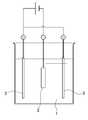
도 1은 본 발명의 제조 방법에 있어서의 전착법에 의한 분말의 도포부착 공정의 일례를 나타내는 개략도이다.BRIEF DESCRIPTION OF THE DRAWINGS It is a schematic diagram which shows an example of the process of apply|coating powder by the electrodeposition method in the manufacturing method of this invention.
본 발명의 희토류 영구자석의 제조 방법은, 상기한 바와 같이 R1-Fe-B계 조성으로 이루어지는 소결 자석체 표면에, 상기 R2로 표시되는 후술하는 희토류 원소의 산화물을 공급하여 열처리를 행하는 것이다.In the method of manufacturing a rare earth permanent magnet of the present invention, as described above, the surface of a sintered magnet body composed of a R1 -Fe-B-based composition is supplied with an oxide of a rare earth element described later represented by R2 to perform heat treatment. .
여기에서, R1-Fe-B계 소결 자석체는 상법에 따라, 모합금을 조분쇄, 미분쇄, 성형, 소결시킴으로써 얻을 수 있다.Here, the R1 -Fe-B-based sintered magnet body can be obtained by coarse pulverizing, fine pulverizing, forming, and sintering the mother alloy according to the conventional method.
또한, 본 발명에서, R, R1 및 R2는 모두 Y 및 Sc를 포함하는 희토류 원소로부터 선택되는 것을 의미하지만, R은 주로 얻어진 자석체에 관하여 사용하고, R1이나 R2는 주로 출발원료에 관하여 사용한다.Further, in the present invention, R, R1 and R2 are all meant to be selected from rare earth elements containing Y and Sc, but R is mainly used for the obtained magnet body, and R1 or R2 is mainly a starting material. Use about
모합금은 R1, Fe, B를 함유한다. R1은 Y 및 Sc를 포함하는 희토류 원소로부터 선택되는 1종 또는 2종 이상이며, 구체적으로는 Y, Sc, La, Ce, Pr, Nd, Sm, Eu, Gd, Tb, Dy, Ho, Er, Yb 및 Lu를 들 수 있고, 바람직하게는 Nd, Pr, Dy를 주체로 한다. 이들 Y 및 Sc를 포함하는 희토류 원소는 합금 전체의 10∼15원자%, 특히 12∼15원자%인 것이 바람직하고, 더욱 바람직하게는 R1 속에 Nd와 Pr 혹은 그 중 어느 1종을 10원자% 이상, 특히 50원자% 이상 함유하는 것이 바람직하다. B는 3∼15원자%, 특히 4∼8원자% 함유하는 것이 바람직하다. 그 외, Al, Cu, Zn, In, Si, P, S, Ti, V, Cr, Mn, Ni, Ga, Ge, Zr, Nb, Mo, Pd, Ag, Cd, Sn, Sb, Hf, Ta, W 중에서 선택되는 1종 또는 2종 이상을 0∼11원자%, 특히 0.1∼5원자% 함유해도 된다. 잔부는 Fe 및 C, N, O 등의 불가피한 불순물이지만, Fe는 50원자% 이상, 특히 65원자% 이상 함유하는 것이 바람직하다. 또한 Fe의 일부, 예를 들면, Fe의 0∼40원자%, 특히 0∼15원자%를 Co로 치환해도 상관없다.The mother alloy contains R1 , Fe and B. R1 is one or two or more selected from rare earth elements including Y and Sc, and specifically, Y, Sc, La, Ce, Pr, Nd, Sm, Eu, Gd, Tb, Dy, Ho, Er , Yb and Lu, and preferably Nd, Pr and Dy. The rare earth elements containing these Y and Sc are preferably 10 to 15 atomic% of the whole alloy, particularly 12 to 15 atomic%, more preferably 10 atomic% of Nd and Pr or any one of them in R1 It is preferable to contain at least 50 atom% or more. It is preferable that B contains 3-15 atomic%, especially 4-8 atomic%. Al, Cu, Zn, In, Si, P, S, Ti, V, Cr, Mn, Ni, Ga, Ge, Zr, Nb, Mo, Pd, Ag, Cd, Sn, Sb, Hf, Ta , 0 to 11 atomic%, particularly 0.1 to 5 atomic%. The remainder is an unavoidable impurity such as Fe and C, N, and O, but it is preferable to contain Fe in an amount of 50 atom% or more, particularly 65 atom% or more. Further, a part of Fe, for example, 0 to 40 atom% of Fe, particularly 0 to 15 atom%, may be substituted with Co.
모합금은 원료 금속 혹은 합금을 진공 혹은 불활성 가스, 바람직하게는 Ar 분위기 중에서 용해한 뒤, 평 몰드나 북 몰드에 주입하거나, 혹은 스트립 캐스팅에 의해 주조함으로써 얻어진다. 또한 본 계 합금의 주상인 R2Fe14B 화합물 조성에 가까운 합금과 소결 온도에서 액상 조제가 되는 R 풍부한 합금을 각각 제작하고, 조분쇄 후에 칭량 혼합하는, 소위 2합금법도 본 발명에는 적용 가능하다. 단, 주상 조성에 가까운 합금에 대하여, 주조시의 냉각 속도나 합금 조성에 의존하여 α-Fe상이 잔존하기 쉬워, R2Fe14B 화합물상의 양을 늘릴 목적으로 필요에 따라 균질화 처리를 시행한다. 그 조건은 진공 혹은 Ar 분위기 중에서 700∼1,200℃에서 1시간 이상 열처리한다. 이 경우, 주상 조성에 가까운 합금은 스트립 캐스팅법으로 얻을 수도 있다. 액상 조제가 되는 R 풍부한 합금에 대해서는 상기 주조법의 이외에, 소위 액체 급랭법이나 스트립 캐스팅법도 적용할 수 있다.The mother alloy is obtained by dissolving the raw metal or alloy in a vacuum or inert gas, preferably Ar atmosphere, and then injecting it into a flat mold or a book mold or casting by strip casting. In addition, the so-called two-alloy method, in which an alloy close to the composition of the R2 Fe14 B compound, which is the main phase of the alloy of the present invention, and an R-rich alloy that is a liquid auxiliary at a sintering temperature are respectively prepared and weighed and mixed after co-grinding, is also applicable to the present invention. . However, for the alloy close to the main phase composition, the α-Fe phase is likely to remain depending on the cooling rate at the time of casting or the alloy composition, and a homogenization treatment is performed as necessary for the purpose of increasing the amount of the R2 Fe14 B compound phase. The conditions are heat treated at 700 to 1,200°C for 1 hour or more in a vacuum or Ar atmosphere. In this case, an alloy close to the columnar composition can also be obtained by strip casting. For the R-rich alloy to be a liquid preparation, in addition to the above casting method, a so-called liquid quenching method or a strip casting method can also be applied.
또한 이하에 기술하는 분쇄 공정에 있어서, R1의 탄화물, 질화물, 산화물, 수산화물 중 적어도 1종 혹은 이것들의 혼합물 또는 복합물을 0.005∼5질량%의 범위에서 합금 분말과 혼합하는 것도 가능하다.In the pulverization process described below, it is also possible to mix at least one of R1 carbides, nitrides, oxides, hydroxides, or mixtures or composites thereof with alloy powders in the range of 0.005 to 5% by mass.
상기 합금은 통상 0.05∼3mm, 특히 0.05∼1.5mm로 조분쇄된다. 조분쇄 공정에는 브라운밀 혹은 수소 분쇄가 사용되고, 스트립 캐스팅에 의해 제작된 합금의 경우에는 수소 분쇄가 바람직하다. 조분은, 예를 들면, 고압 질소를 사용한 제트밀에 의해 통상 0.2∼30㎛, 특히 0.5∼20㎛로 미분쇄된다. 미분말은 자계중 압축 성형기로 성형되고, 소결로에 투입된다. 소결은 진공 혹은 불활성 가스 분위기 중, 통상 900∼1,250℃, 특히 1,000∼1,100℃에서 행해진다.The alloy is usually pulverized to 0.05 to 3 mm, particularly 0.05 to 1.5 mm. Brown mill or hydrogen grinding is used in the coarse grinding process, and in the case of alloys produced by strip casting, hydrogen grinding is preferred. The coarse powder is usually pulverized to 0.2 to 30 µm, particularly 0.5 to 20 µm, usually by a jet mill using high pressure nitrogen. The fine powder is molded in a compression molding machine in a magnetic field, and is put into a sintering furnace. Sintering is usually performed in a vacuum or inert gas atmosphere at 900 to 1,250°C, particularly 1,000 to 1,100°C.
여기에서 얻어진 소결 자석은 정방정 R2Fe14B 화합물을 주상으로 하여 60∼99체적%, 특히 바람직하게는 80∼98체적% 함유하고, 잔부는 0.5∼20체적%의 R이 풍부한 상, 0∼10체적%의 B가 풍부한 상 및 불가피적 불순물에 의해 생성한 혹은 첨가에 의한 탄화물, 질화물, 산화물, 수산화물 중 적어도 1종 혹은 이것들의 혼합물 또는 복합물로 이루어진다.The sintered magnet obtained here contains 60 to 99% by volume, particularly preferably 80 to 98% by volume, with a tetragonal R2 Fe14 B compound as the main phase, and the balance is 0.5 to 20% by volume of R-rich phase, 0 It is composed of at least one or more mixtures or composites of carbides, nitrides, oxides and hydroxides produced or added by ∼10% by volume of B-rich phase and inevitable impurities.
얻어진 소결 블록은 소정 형상으로 연삭된다. 그 크기는 특별히 제한되지 않지만, 본 발명에 있어서, 자석 표면에 도포부착시킨 R2의 산화물을 함유하는 분말로부터 자석체에 흡수되는 R2의 양은 자석체의 비표면적이 큰, 즉 치수가 작을수록 많아지므로, 상기 형상의 최대부의 치수가 100mm 이하, 바람직하게는 50mm 이하, 특히 바람직하게는 20mm 이하이고, 또한 자기 이방성화한 방향의 치수가 10mm 이하, 바람직하게는 5mm 이하, 특히 2mm 이하인 것이 바람직하다. 보다 바람직하게는 자기 이방성화한 방향의 치수가 1mm 이하이다. 또한, 본 발명에서는, 후술하는 전착법에 의해 상기 분말을 도포부착시키는 것이므로, 보다 대면적에 대해서도 양호하고 또한 단시간에 처리하는 것이 가능하며, 최대부의 치수가 100mm를 초과하는 것, 자기 이방성화한 방향의 치수가 10mm를 초과하는 것이어도, 양호하게 처리하는 것이 가능하다. 또한, 상기 최대부의 치수 및 자기 이방성화한 방향의 치수의 하한에 특별히 제한은 없고 적당히 선정되지만, 통상은 상기 형상의 최대부의 치수는 0.1mm 이상, 자기 이방성화한 방향의 치수는 0.05mm 이상으로 하는 것이 바람직하다.The obtained sintered block is ground into a predetermined shape. Although the size is not particularly limited, in the present invention, the amount of R2 absorbed by the magnet body from the powder containing the oxide of R2 applied and adhered to the magnet surface is larger as the specific surface area of the magnet body, that is, the smaller the dimension. As it increases, the dimension of the maximum portion of the shape is 100 mm or less, preferably 50 mm or less, particularly preferably 20 mm or less, and it is preferable that the dimension in the direction of magnetic anisotropy is 10 mm or less, preferably 5 mm or less, especially 2 mm or less. Do. More preferably, the dimension in the direction of magnetic anisotropy is 1 mm or less. In addition, in the present invention, since the powder is applied and adhered by the electrodeposition method described later, it is possible to treat the material with a larger area and to process it in a short time, and the dimension of the largest portion exceeds 100 mm, and anisotropically Even if the dimension in the direction exceeds 10 mm, it can be processed satisfactorily. In addition, although there is no restriction|limiting in particular in the lower limit of the dimension of the said largest part and the direction of the self-anisotropic direction, it is selected suitably, Usually, the dimension of the largest part of the said shape is 0.1 mm or more, and the dimension of the magnetic anisotropic direction is 0.05 mm or more. It is desirable to do.
연삭 가공된 자석체 표면에는 R2의 산화물을 함유하는 분말을 전착법에 의해 존재시킨다. 이 경우, R2는 Y 및 Sc를 포함하는 희토류 원소로부터 선택되는 1종 또는 2종 이상이고, R2 중 10원자% 이상, 보다 바람직하게는 20원자% 이상, 특히 40원자% 이상의 Dy 또는 Tb를 포함하는 것이 바람직하다. 이 경우, 상기 R2에 상기한 바와 같이 10원자% 이상의 Dy 및/또는 Tb가 포함되고, 또한 R2에서의 Nd와 Pr의 합계 농도가 상기 R1에서의 Nd와 Pr의 합계 농도보다 낮은 것이 본 발명의 목적에서 보다 바람직하다.A powder containing an oxide of R2 is present on the surface of the ground magnet body by electrodeposition. In this case, R2 is one or two or more selected from rare earth elements including Y and Sc, and 10 or more atomic atoms of R2 , more preferably 20 or more atomic atoms, particularly 40 or more atomic atoms, Dy or Tb It is preferred to include. In this case, the above R2 contains 10 atomic% or more of Dy and/or Tb as described above, and the total concentration of Nd and Pr in R2 is lower than the total concentration of Nd and Pr in R1 . It is more preferred for the purposes of the present invention.
자석 표면 공간에서의 분말의 존재량은 높을수록 흡수되는 R2량이 많아지므로, 본 발명에서의 효과를 보다 확실하게 달성하기 위하여, 상기 분말의 존재량은 면 밀도로 10㎍/mm2 이상인 것이 바람직하고, 더욱 바람직하게는 60㎍/mm2 이상이다.Since the amount of R2 absorbed increases as the amount of powder present in the magnet surface space increases, it is preferable that the amount of powder present is 10 μg/mm2 or more in terms of surface density in order to more reliably achieve the effect in the present invention. And more preferably 60 μg/mm2 or more.
상기 분말의 입자직경은 R2 성분이 자석에 흡수될 때의 반응성에 영향을 주고, 입자가 작을수록 반응에 관여하는 접촉 면적이 증대한다. 본 발명에서의 효과를 보다 효과적으로 달성시키기 위해서는, 존재시키는 분말의 평균 입자직경은 100㎛ 이하, 바람직하게는 10㎛ 이하가 바람직하다. 그 하한은 특별히 제한되지 않지만 1nm 이상이 바람직하다. 또한, 이 평균 입자직경은, 예를 들면, 레이저 회절법 등에 의한 입도 분포 측정 장치 등을 사용하여 질량평균값 D50(즉 누적 질량이 50%가 될 때의 입자직경 또는 메디안 직경) 등으로서 구할 수 있다.The particle diameter of the powder affects the reactivity when the R2 component is absorbed by the magnet, and the smaller the particle, the larger the contact area involved in the reaction. In order to achieve the effect in the present invention more effectively, the average particle diameter of the powder to be present is preferably 100 µm or less, preferably 10 µm or less. The lower limit is not particularly limited, but 1 nm or more is preferable. In addition, this average particle diameter can be obtained as a mass average value D50 (that is, a particle diameter or a median diameter when the cumulative mass becomes 50%) using, for example, a particle size distribution measuring device such as laser diffraction. have.
본 발명에서의 R2의 산화물이란 바람직하게는 R22O3이지만, 이외의 R2On(n은 임의의 정수)이나, 금속 원소에 의해 R2의 일부를 치환한 혹은 안정화된 것 등, 본 발명의 효과를 달성할 수 있는 R2와 산소를 포함하는 산화물을 가리킨다.The oxide of R2 in the present invention is preferably R22 O3, but other R2 On (n is an arbitrary integer) or a part of R2 substituted or stabilized by a metal element, etc. , Refers to an oxide containing R2 and oxygen that can achieve the effects of the present invention.
이 경우, 자석체 표면에 존재시키는 분말은 R2의 산화물을 함유하고, 이 밖에 R3(R3은 Y 및 Sc를 포함하는 희토류 원소로부터 선택되는 1종 또는 2종 이상)의 불화물, 산불화물, 탄화물, 질화물, 수산화물, 수소화물 중 적어도 1종 혹은 이것들의 혼합물 또는 복합물을 포함해도 된다. 또한 분말의 분산성이나 화학적·물리적 흡착을 촉진하기 위하여, 붕소, 질화 붕소, 실리콘, 탄소 등의 미분말이나 스테아르산 등의 유기 화합물을 포함할 수도 있다. 본 발명의 효과를 고효율로 달성하기 위해서는, R2의 산화물이 분말 전체에 대하여 10질량% 이상, 바람직하게는 20질량% 이상 포함된다. 특히, 주성분으로서 R2의 산화물이 분말 전체에 대하여 50질량% 이상, 보다 바람직하게는 70질량% 이상, 더욱 바람직하게는 90질량% 이상 함유되는 것이 추장된다.In this case, the powder present on the surface of the magnet body contains an oxide of R2 , and in addition, R3 (one or two or more of R3 is selected from rare earth elements including Y and Sc) fluoride and acid fluoride , Carbides, nitrides, hydroxides, hydrides, or mixtures or composites thereof. In addition, in order to promote the dispersibility or chemical and physical adsorption of the powder, it may also include fine powders such as boron, boron nitride, silicon, carbon, or organic compounds such as stearic acid. In order to achieve the effect of the present invention with high efficiency, the oxide of R2 is contained in an amount of 10% by mass or more, preferably 20% by mass or more, with respect to the entire powder. In particular, it is recommended that the oxide of R2 as a main component is contained in an amount of 50% by mass or more, more preferably 70% by mass or more, and even more preferably 90% by mass or more with respect to the entire powder.
본 발명에서는, 분말을 자석체 표면에 존재시키는 방법(분말 처리 방법)으로서 상기 분말을 용매 중에 분산시킨 전착액 중에 상기 소결 자석체를 침지하고, 전착법에 의해 소결 자석체 표면에 상기 분말을 도포부착시키는 방법이 채용되며, 이 방법에 의하면, 종래의 침지법과 비교하여, 1회의 작업으로 보다 다량의 상기 분말을 소결 자석체 표면에 도포부착시킬 수 있다. 이 경우, 상기 분말을 분산시키는 용매는 물이어도 유기 용매이어도 되고, 유기 용매로서는, 특별히 제한은 없지만, 에탄올, 아세톤, 메탄올, 아이소프로필알코올 등이 예시되며, 이것들 중에서는 에탄올이 적합하게 사용된다.In the present invention, as a method of presenting the powder on the surface of the magnet body (powder treatment method), the sintered magnet body is immersed in an electrodeposition solution in which the powder is dispersed in a solvent, and the powder is applied to the surface of the sintered magnet body by an electrodeposition method. A method of adhering is employed, and according to this method, a larger amount of the powder can be applied and adhered to the surface of the sintered magnet body in one operation, as compared with the conventional immersion method. In this case, the solvent for dispersing the powder may be water or an organic solvent, and the organic solvent is not particularly limited, but ethanol, acetone, methanol, isopropyl alcohol, and the like are exemplified. Among them, ethanol is suitably used.
상기 전착액 중의 분말의 분산량에 특별히 제한은 없지만, 양호하고 또한 효율적으로 분말을 도포부착시키기 위하여 분산량이 질량 분율 1% 이상, 특히 10% 이상, 더욱이 20% 이상의 슬러리로 하는 것이 바람직하다. 또한, 분산량이 지나치게 많아도 균일한 분산액이 얻어지지 않는 등의 문제가 발생하기 때문에, 상한은 질량 분율 70% 이하, 특히 60% 이하, 더욱이 50% 이하로 하는 것이 바람직하다. 이 경우, 분산제로서 계면활성제를 전착액에 첨가하여 상기 분말의 분산성을 높일 수 있다.The dispersion amount of the powder in the electrodeposition liquid is not particularly limited, but in order to apply the powder efficiently and efficiently, the dispersion amount is preferably a slurry having a mass fraction of 1% or more, particularly 10% or more, and further 20% or more. Moreover, even if the amount of dispersion is too large, problems such as the inability to obtain a uniform dispersion may occur, so the upper limit is preferably 70% or less, particularly 60% or less, and 50% or less. In this case, a surfactant can be added to the electrodeposition solution as a dispersant to increase the dispersibility of the powder.
전착법에 의한 상기 분말의 도포부착 조작은 공지의 방법에 따라 행하면 되고, 예를 들면, 도 1에 도시한 바와 같이, 상기 분말을 분산시킨 전착액(1) 중에 소결 자석체(2)를 침지함과 아울러, 하나 또는 복수의 상대극(3)을 배치하고, 소결 자석체(2)를 음극(캐소드) 혹은 정극(애노드), 상대극(3)을 정극(애노드) 혹은 음극(캐소드)으로 하여 직류의 전기 회로를 구성하고, 소정의 직류전압을 인가함으로써 전착을 행할 수 있다. 또한, 도 1에서는, 소결 자석체(2)를 음극(캐소드), 상대극(3)을 정극(애노드)으로 하고 있지만, 사용하는 전착분의 극성은 계면활성제에 의해 변화되기 때문에, 그것에 따라 상기 소결 자석체(2) 및 상대극(3)의 극성이 설정된다.The coating and adhesion operation of the powder by the electrodeposition method may be performed according to a known method. For example, as shown in FIG. 1, the
이 경우, 상기 상대극은 특별히 제한은 없고 공지의 재료로부터 적당히 선정하여 사용할 수 있고, 예를 들면, 스테인리스 스틸판을 적합하게 사용할 수 있다. 또한 통전 조건도 적당히 설정하면 되어, 특별히 제한되는 것은 아니지만, 통상은 소결 자석체(2)와 상대극(3) 사이에 1∼300V, 특히 5∼50V의 전압을 1∼300초, 특히 5∼60초 인가할 수 있다. 또한, 전착액의 온도도 적당하게 조정되며 특별히 제한은 없지만, 통상은 10∼40℃로 할 수 있다.In this case, the counter electrode is not particularly limited and can be appropriately selected from known materials and used, for example, a stainless steel plate can be suitably used. Also, the energization conditions may be appropriately set, and is not particularly limited, but usually, a voltage of 1 to 300 V, particularly 5 to 50 V, between the
이와 같이, R2의 산화물을 함유하는 분말을 전착법에 의해 자석 표면에 도포부착하여 자석 표면에 당해 분말을 존재시킨 상태에서, 이 자석과 분말은 진공 혹은 아르곤(Ar), 헬륨(He) 등의 불활성 가스 분위기 중에서 열처리된다(이후, 이 처리를 흡수 처리라고 칭함). 흡수 처리 온도는 자석체의 소결 온도 이하이다. 처리 온도의 한정 이유는 이하와 같다.As described above, in the state where the powder containing the oxide of R2 is applied and adhered to the surface of the magnet by the electrodeposition method and the powder is present on the surface of the magnet, the magnet and the powder are vacuum or argon (Ar), helium (He), etc. Heat treatment in an inert gas atmosphere of (hereinafter, this treatment will be referred to as absorption treatment). The absorption treatment temperature is below the sintering temperature of the magnet body. The reason for limiting the treatment temperature is as follows.
즉 당해 소결 자석의 소결 온도(TS℃라고 칭함)보다 높은 온도로 처리하면, (1) 소결 자석의 조직이 변질되어, 높은 자기 특성이 얻어지지 않게 되고, (2) 열변형에 의해 가공 치수를 유지할 수 없게 되며, (3) 확산시킨 R이 자석의 결정립계면뿐만 아니라 내부에까지 확산해 버려 잔류 자속밀도가 저하되는 등의 문제가 발생하기 때문에, 처리 온도는 소결 온도 이하, 바람직하게는 (TS-10)도 이하로 한다. 또한, 온도의 하한은 적당히 선정되지만, 통상 350℃ 이상이다. 흡수 처리 시간은 1분∼100시간이다. 1분 미만에서는 흡수 처리가 완료되지 않고, 100시간을 초과하면, 소결 자석의 조직이 변질되고, 불가피적인 산화나 성분의 증발이 자기 특성에 나쁜 영향을 준다고 하는 문제가 발생하기 쉽다. 보다 바람직하게는 5분∼8시간, 특히 10분∼6시간이다.That is, when the sintered magnet is treated at a temperature higher than the sintering temperature (referred to as TS ℃), (1) the structure of the sintered magnet is deteriorated, high magnetic properties are not obtained, and (2) processing dimensions are caused by thermal deformation. Since it becomes impossible to maintain and (3) the diffused R diffuses not only to the grain boundary of the magnet but also to the inside, resulting in a decrease in the residual magnetic flux density, the treatment temperature is below the sintering temperature, preferably (TS- 10) is also set as follows. In addition, although the lower limit of the temperature is appropriately selected, it is usually 350°C or higher. The absorption treatment time is 1 minute to 100 hours. If the absorption treatment is not completed in less than 1 minute, and if it exceeds 100 hours, the structure of the sintered magnet is deteriorated, and the problem that unavoidable oxidation or evaporation of components adversely affects the magnetic properties tends to occur. It is more preferably 5 minutes to 8 hours, particularly 10 minutes to 6 hours.
이상과 같은 흡수 처리에 의해, 자석 내의 희토류가 풍부한 입계상 성분에 자석 표면에 존재시킨 분말에 포함되어 있던 R2가 농화되고, 이 R2가 R2Fe14B 주상 입자의 표층부 부근에서 치환된다.Through the above absorption treatment, R2 contained in the powder present on the magnet surface is enriched in the grain boundary phase component rich in rare earths in the magnet, and R2 is substituted near the surface layer portion of the R2 Fe14 B columnar particles. .
여기에서, R2의 산화물에 포함되는 희토류 원소는 Y 및 Sc를 포함하는 희토류 원소로부터 선택되는 1종 또는 2종 이상이지만, 상기 표층부에 농화되어 결정 자기 이방성을 높이는 효과가 특히 큰 원소는 Dy, Tb이므로, 전술한 바와 같이, 분말에 포함되어 있는 희토류 원소로서는 Dy 및 Tb의 비율이 합계로 10원자% 이상인 것이 적합하다. 더욱 바람직하게는 20원자% 이상이다. 또한 R2에서의 Nd와 Pr의 합계 농도가 R1의 Nd와 Pr의 합계 농도보다 낮은 것이 바람직하다.Here, the rare earth element contained in the oxide of R2 is one or two or more selected from rare earth elements including Y and Sc, but the element having a particularly large effect of enhancing crystal magnetic anisotropy by thickening in the surface layer portion is Dy, Since Tb, as described above, it is preferable that the ratio of Dy and Tb is 10 atom% or more in total as the rare earth element contained in the powder. More preferably, it is 20 atomic% or more. It is also preferred that the total concentration of Nd and Pr in R2 is lower than the total concentration of Nd and Pr in R1.
이 흡수 처리의 결과, 잔류 자속밀도의 저감을 거의 수반하지 않고 R-Fe-B계 소결 자석의 보자력이 효율적으로 증대된다.As a result of this absorption treatment, the coercive force of the R-Fe-B-based sintered magnet is effectively increased with little reduction in the residual magnetic flux density.
상기 흡수 처리는 상기한 전착법에 의해 소결 자석체 표면에 상기 R2를 포함하는 분말을 도포부착시키고, 이 소결 자석체 표면에 상기 분말을 부착시킨 상태에서 열처리함으로써 행할 수 있고, 이 경우, 상기 흡수 처리에 있어서, 자석은 분말에 씌워지고, 자석끼리는 떨어져서 존재하므로, 고온에서의 열처리임에도 불구하고, 흡수 처리 후에 자석끼리 용착하지 않는다. 또한 분말도 열처리 후에 자석에 고착되지 않기 때문에, 열처리용 용기에 대량으로 자석을 투입하여 처리하는 것이 가능하여, 본 발명에 의한 제조 방법은 생산성도 우수하다.The absorption treatment can be carried out by applying and depositing the powder containing R2 on the surface of the sintered magnet body by the electrodeposition method described above, and heat treatment in a state where the powder is attached to the surface of the sintered magnet body, in this case, the In the absorption treatment, the magnets are covered with powder, and the magnets are separated, so that the magnets do not weld to each other after the absorption treatment, despite heat treatment at high temperatures. In addition, since the powder is not adhered to the magnet after heat treatment, it is possible to inject and process the magnet in a large amount to the heat treatment container, and the production method according to the present invention is also excellent in productivity.
또한 본 발명에서는, 상기 분말을 상기한 전착법에 의해 소결 자석체 표면에 도포부착하기 때문에, 인가 전압이나 인가 시간을 조절함으로써 용이하게 분말의 도포부착량을 컨트롤할 수 있어, 필요량의 분말을 낭비 없이 확실하게 자석체 표면에 공급할 수 있다. 또한 막 두께의 편차가 작고 치밀하여 도포부착 불균일이 적은 분말의 도포막을 확실하게 자석체 표면에 형성할 수 있기 때문에, 최소한의 분말로 보자력의 증대가 포화에 달할 때까지의 흡수 처리를 행할 수 있어, 대단히 효율적이고 또한 경제적인데다, 단시간에 양호한 분말의 막을 대면적에 걸쳐 형성할 수 있다. 또한 더욱이 전착법에 의해 형성되는 분말의 도포막은 침지법이나 스프레이 도포에 의한 막 보다도 밀착성이 우수하여, 작업성 좋고 확실하게 상기 흡수 처리를 행할 수 있어, 이 점에서도 본 발명의 방법은 대단히 효율적이다.In addition, in the present invention, since the powder is applied and adhered to the surface of the sintered magnet body by the electrodeposition method described above, it is possible to easily control the applied amount of the powder by adjusting the applied voltage or the applied time, without wasting the required amount of powder. It can be surely supplied to the surface of the magnet body. In addition, since the film thickness of the film is small and the variation is small and the coating film of powder with little coating adhesion non-uniformity can be reliably formed on the surface of the magnet body, absorption processing can be performed until the increase in coercive force reaches saturation with minimal powder. It is very efficient and economical, and a good powder film can be formed over a large area in a short time. Moreover, the coating film of the powder formed by the electrodeposition method is superior in adhesion to the film by the immersion method or spray coating, and the workability can be reliably performed and the absorption treatment can be carried out. In this regard, the method of the present invention is also very efficient. .
본 발명의 제조 방법에서는, 특별히 제한되는 것은 아니지만, 상기 흡수 처리 후, 시효 처리를 시행하는 것이 바람직하다. 이 시효 처리로서는 흡수 처리 온도 미만, 바람직하게는 200℃ 이상이고 흡수 처리 온도보다 10℃ 낮은 온도 이하, 더욱 바람직하게는 350℃ 이상이고 흡수 처리 온도보다 10℃ 낮은 온도 이하인 것이 바람직하다. 또한 그 분위기는 진공 혹은 Ar, He 등의 불활성 가스 중인 것이 바람직하다. 시효 처리의 시간은 1분∼10시간, 바람직하게는 10분∼5시간, 특히 30분∼2시간이다.In the production method of the present invention, although not particularly limited, it is preferable to perform an aging treatment after the absorption treatment. As the aging treatment, it is preferable that the temperature is less than the absorption treatment temperature, preferably 200°C or higher, 10°C or lower than the absorption treatment temperature, more preferably 350°C or higher and 10°C or lower than the absorption treatment temperature. In addition, the atmosphere is preferably in an inert gas such as vacuum or Ar, He. The time of the aging treatment is 1 minute to 10 hours, preferably 10 minutes to 5 hours, particularly 30 minutes to 2 hours.
또한, 상기 전착법에 의해 분말을 소결 자석체에 존재시키기 전의 상기한 소결 자석체의 연삭 가공시에 있어서, 연삭 가공기의 냉각액에 수계의 것을 사용하거나, 혹은 가공시에 연삭면이 고온에 노출되는 경우, 피연삭면에 산화막이 발생하기 쉬워, 이 산화막이 분말로부터 자석체로의 R2 성분의 흡수 반응을 방해하는 경우가 있다. 이러한 경우에는, 알칼리, 산 혹은 유기 용제 중 어느 1종 이상을 사용하여 세정하거나, 혹은 숏 블라스팅을 시행하여, 그 산화막을 제거함으로써 적절한 흡수 처리를 할 수 있다.In addition, in the grinding process of the above-mentioned sintered magnet body before the powder is present in the sintered magnet body by the electrodeposition method, a water-based one is used as a cooling liquid of the grinding machine, or the grinding surface is exposed to high temperatures during processing. In this case, an oxide film is easily generated on the surface to be polished, and this oxide film may interfere with the absorption reaction of the R2 component from the powder to the magnet body. In this case, an appropriate absorption treatment can be performed by washing with any one or more of alkali, acid, or organic solvent, or by performing shot blasting to remove the oxide film.
알칼리로서는 파이로인산 포타슘, 파이로인산 소듐, 시트르산 포타슘, 시트르산 소듐, 아세트산 포타슘, 아세트산 소듐, 옥살산 포타슘, 옥살산 소듐 등, 산으로서는 염산, 질산, 황산, 아세트산, 시트르산, 타타르산 등, 유기 용제로서는 아세톤, 메탄올, 에탄올, 아이소프로필알코올 등을 사용할 수 있다. 이 경우, 상기 알칼리나 산은 자석체를 침식하지 않는 적시 농도의 수용액으로서 사용할 수 있다. 더욱이, 상기 소결 자석체의 표면층을 상기 분말을 소결 자석체에 존재시키기 전에 숏 블라스팅으로 제거할 수도 있다.Examples of the alkali include potassium pyrophosphate, sodium pyrophosphate, potassium citrate, sodium citrate, potassium acetate, sodium acetate, potassium oxalate, sodium oxalate, and the like as acids, hydrochloric acid, nitric acid, sulfuric acid, acetic acid, citric acid, and tartaric acid. Acetone, methanol, ethanol, and isopropyl alcohol can be used. In this case, the alkali or acid can be used as a timely concentration aqueous solution that does not erode the magnet body. Moreover, the surface layer of the sintered magnet body may be removed by short blasting before the powder is present in the sintered magnet body.
또한 상기 흡수 처리 혹은 그것에 계속되는 시효 처리를 시행한 자석에 대하여, 알칼리, 산 혹은 유기 용제 중 어느 1종 이상에 의해 세정하거나, 실용 형상으로 연삭할 수도 있다. 더욱이, 이러한 흡수 처리, 시효 처리, 세정 또는 연삭 후에 도금 또는 도장을 시행할 수도 있다.Further, the magnet subjected to the absorption treatment or the aging treatment subsequent thereto may be cleaned with any one or more of alkali, acid, or organic solvent, or ground into a practical shape. Moreover, plating or painting may also be performed after such absorption treatment, aging treatment, cleaning or grinding.
(실시예)(Example)
이하, 본 발명의 구체적 태양에 대하여 실시예로써 상세하게 설명하지만, 본 발명은 이것에 한정되는 것은 아니다. 또한, 하기 예에서, 산화 Tb의 자석체 표면 에 대한 면 밀도는 분말 처리 후의 자석 질량 증가와 그 표면적으로부터 산출했다.Hereinafter, specific embodiments of the present invention will be described in detail as examples, but the present invention is not limited thereto. In addition, in the following example, the surface density of the oxide Tb on the surface of the magnet body was calculated from the increase in the magnet mass after the powder treatment and its surface area.
[실시예 1][Example 1]
Nd가 14.5원자%, Cu가 0.2원자%, B가 6.2원자%, Al이 1.0원자%, Si가 1.0원자%, Fe가 잔부로 이루어지는 박판 형상의 합금을, 순도 99질량% 이상의 Nd, Al, Fe, Cu 메탈, 순도 99.99질량%의 Si, 페로보론을 사용하여 Ar 분위기 중에서 고주파 용해한 후, 구리제 단롤에 주탕하는 소위 스트립 캐스팅법에 의해 박판 형상의 합금으로 했다. 얻어진 합금을 실온에서 0.11MPa의 수소에 노출하여 수소를 흡장시킨 후, 진공 배기를 행하면서 500℃까지 가열하여 부분적으로 수소를 방출시키고, 냉각하고 나서 체에 걸어, 50메시 이하의 조분말로 했다.Nd is 14.5 atomic%, Cu is 0.2 atomic%, B is 6.2 atomic%, Al is 1.0 atomic%, Si is 1.0 atomic%, Fe is a thin-walled alloy composed of the remainder, purity of 99 mass% or more Nd, Al, After high-frequency dissolution in an Ar atmosphere using Fe, Cu metal, Si of 99.99% by mass, and boroborone, a thin-plate alloy was prepared by a so-called strip casting method in which a single roll made of copper was poured. The obtained alloy was exposed to 0.11 MPa hydrogen at room temperature to store hydrogen, and then heated to 500°C while evacuating to partially release hydrogen, and after cooling, sieved to obtain a coarse powder of 50 mesh or less. .
상기 조분말을, 고압 질소 가스를 사용한 제트밀로 분말의 중량 중위 입경 5㎛로 미분쇄했다. 얻어진 이 혼합 미분말을 질소 분위기하에 15kOe의 자계 중에서 배향시키면서, 약 1ton/cm2의 압력으로 블록 형상으로 성형했다. 이 성형체를 Ar 분위기의 소결로 내에 투입하고, 1,060℃에서 2시간 소결하여 자석 블록을 얻었다. 이 자석 블록을 다이아몬드 커터를 사용하여 전체면 연삭 가공한 후, 알칼리 용액, 순수, 질산, 순수의 순으로 세정하고 건조시켜, 17mm×17mm×2mm(자기 이방성화한 방향)의 블록 형상 자석체를 얻었다.The crude powder was finely pulverized to a median particle size of 5 µm by a jet mill using high pressure nitrogen gas. The resultant mixed fine powder was molded into a block shape at a pressure of about 1 ton/cm2 while oriented in a magnetic field of 15 kOe under a nitrogen atmosphere. This molded product was put into an sintering furnace in an Ar atmosphere, and sintered at 1,060°C for 2 hours to obtain a magnetic block. After grinding the entire surface of this magnetic block using a diamond cutter, it is washed with an alkali solution, pure water, nitric acid, and pure water, and then dried to obtain a block-shaped magnetic body of 17 mm × 17 mm × 2 mm (self-anisotropic direction). Got.
이어서, 평균 분말 입경이 0.2㎛의 산화 터븀을 질량 분율 40%로 물과 혼합하고, 이것에 산화 터븀의 분말을 잘 분산시켜 슬러리로 만들고 이 슬러리를 전착액으로 했다.Subsequently, terbium oxide having an average powder particle diameter of 0.2 µm was mixed with water at a mass fraction of 40%, and the powder of terbium oxide was well dispersed therein to form a slurry, and this slurry was used as an electrodeposition solution.
도 1과 같이, 이 슬러리(1) 중에 상기 자석체(2)를 침지함과 아울러, 이 자석체(2)와 20mm의 간격을 가지고 한 쌍의 스테인리스 스틸판(SUS304)을 상대극(3)으로서 배치하고, 자석체(2)를 캐소드, 상대극(3)을 애노드로 하여 전기 회로를 구성하고, 직류전압 10V를 7초간 인가하여 전착을 행했다. 전착액(슬러리)으로부터 끌어올린 자석체를 즉시 열풍에 의해 건조시켜, 자석체 표면에 상기 산화 터븀 분말의 박막을 형성했다. 자석체 표면의 산화 터븀의 면 밀도는 100㎍/mm2이었다.As shown in FIG. 1, while immersing the
이 표면에 산화 터븀 분말의 박막을 형성한 자석체를 Ar 분위기 중, 900℃에서 5시간 열처리하여 흡수 처리를 시행하고, 또한 500℃에서 1시간 시효 처리하고 급랭함으로써 자석체를 얻었다. 얻어진 자석체는 흡수 처리에 의해 720kA/m의 보자력 증대가 확인되었다.The magnet body on which the thin film of terbium oxide powder was formed on this surface was heat-treated at 900°C for 5 hours in an Ar atmosphere, and then subjected to absorption treatment, followed by aging treatment at 500°C for 1 hour to obtain a magnet body. The resulting magnet body was confirmed to have an increase in coercive force of 720 kA/m by absorption treatment.
[실시예 2][Example 2]
실시예 1과 동일하게 하여, 17mm×17mm×2mm(자기 이방성화한 방향)의 블록 형상 자석체를 준비했다. 또한 평균 분말 입경이 0.2㎛의 산화 터븀을 질량 분율 40%로 에탄올과 혼합하고, 잘 분산시켜 슬러리로 만들고 이 슬러리를 전착액으로 했다.In the same manner as in Example 1, a block-shaped magnet body having a size of 17 mm × 17 mm × 2 mm (magnetic anisotropy) was prepared. Further, terbium oxide having an average powder particle diameter of 0.2 µm was mixed with ethanol in a mass fraction of 40%, and well dispersed to make a slurry, and this slurry was used as an electrodeposition solution.
이 슬러리 중에 준비한 자석체를 침지하고, 실시예 1과 마찬가지로 상대극을 배치하여 자석체를 캐소드, 상대극을 애노드로 하고, 자석체와 상대극 사이에 직류전압 10V를 10초간 인가하여 전착을 행했다. 전착액(슬러리)으로부터 끌어올린 자석체를 즉시 열풍에 의해 건조시켜, 자석체 표면에 상기 산화 터븀 분말의 박막을 형성했다. 자석체 표면의 산화 터븀의 면 밀도는 100㎍/mm2이었다.The prepared magnet body was immersed in this slurry, and a counter electrode was placed in the same manner as in Example 1 to make the magnet body a cathode and a counter electrode as an anode, and electrodeposition was performed by applying a DC voltage of 10 V between the magnet body and the counter electrode for 10 seconds. . The magnet body pulled up from the electrodeposition liquid (slurry) was immediately dried by hot air to form a thin film of the above-described terbium oxide powder on the magnet body surface. The surface density of terbium oxide on the surface of the magnet body was 100 µg/mm2 .
이 표면에 산화 터븀 분말의 박막을 형성한 자석체를 Ar 분위기 중, 900℃에서 5시간 열처리하여 흡수 처리를 시행하고, 또한 500℃에서 1시간 시효 처리하고 급랭함으로써 자석체를 얻었다. 얻어진 자석체는 흡수 처리에 의해 720kA/m의 보자력 증대가 확인되었다.The magnet body on which the thin film of terbium oxide powder was formed on this surface was heat-treated at 900°C for 5 hours in an Ar atmosphere, and then subjected to absorption treatment, followed by aging treatment at 500°C for 1 hour to obtain a magnet body. The resulting magnet body was confirmed to have an increase in coercive force of 720 kA/m by absorption treatment.
[비교예 1][Comparative Example 1]
실시예 1과 동일하게 하여, 17mm×17mm×2mm(자기 이방성화한 방향)의 블록 형상 자석체를 준비했다. 또한 평균 분말 입경이 0.2㎛의 산화 터븀을 질량 분율 40%로 물과 혼합하고, 잘 분산시켜 슬러리로 했다.In the same manner as in Example 1, a block-shaped magnet body having a size of 17 mm × 17 mm × 2 mm (magnetic anisotropy) was prepared. Further, terbium oxide having an average powder particle diameter of 0.2 µm was mixed with water at a mass fraction of 40%, and dispersed well to obtain a slurry.
이 슬러리 중에 자석체를 7초간 침지시킨 후, 즉시 열풍에 의해 건조시켜, 산화 터븀을 자석체 표면에 도포했다. 자석체 표면의 산화 터븀의 면 밀도는 20㎍/mm2이었다.After immersing the magnet body in this slurry for 7 seconds, it was immediately dried by hot air, and terbium oxide was applied to the surface of the magnet body. The surface density of terbium oxide on the surface of the magnet body was 20 µg/mm2 .
이 표면에 산화 터븀 분말의 박막을 형성한 자석체를 Ar 분위기 중, 900℃에서 5시간 열처리하여 흡수 처리를 시행하고, 또한 500℃에서 1시간 시효 처리하고 급랭함으로써 자석체를 얻었다. 얻어진 자석체는 흡수 처리에 의해 360kA/m의 보자력 증대가 확인되었다.The magnet body on which the thin film of terbium oxide powder was formed on this surface was heat-treated at 900°C for 5 hours in an Ar atmosphere, and then subjected to absorption treatment, followed by aging treatment at 500°C for 1 hour to obtain a magnet body. The resulting magnet body was confirmed to have an increase in coercive force of 360 kA/m by absorption treatment.
Claims (11)
Translated fromKoreanR2의 산화물을 함유하는 분말을 20%~70%의 질량 분율로 수계 또는 유기계의 용매에 분산시킨 슬러리에 상기 소결 자석체를 침지하고, 전착을 행하는 것을 특징으로 하는 희토류 영구자석의 제조 방법.According to claim 1,
A method for producing a rare earth permanent magnet, characterized in that the sintered magnet body is immersed in a slurry in which a powder containing an oxide of R2 is dispersed in an aqueous or organic solvent at a mass fraction of 20% to 70%.
전착액이 계면활성제를 분산제로서 함유하는 것인 것을 특징으로 하는 희토류 영구자석의 제조 방법.The method of claim 1 or 2,
A method for producing a rare earth permanent magnet, characterized in that the electrodeposition liquid contains a surfactant as a dispersant.
R2의 산화물을 함유하는 분말의 평균 입자직경이 100㎛ 이하인 것을 특징으로 하는 희토류 영구자석의 제조 방법.The method of claim 1 or 2,
Method for producing a permanent magnet of rare earth, characterized in that the average particle diameter of the powder containing the oxide of R2 is 100 μm or less.
R2의 산화물을 함유하는 분말의 소결 자석체 표면에 대한 존재량이 상기 소결 자석체 표면의 면 밀도로 60㎍/mm2 이상인 것을 특징으로 하는 희토류 영구자석의 제조 방법.The method according to claim 1 or 2,
A method for producing a permanent magnet of rare earth, characterized in that the amount of the powder containing the oxide of R2 on the surface of the sintered magnet body is 60 µg/mm2 or more as the surface density of the surface of the sintered magnet body.
R2의 산화물의 R2에 10원자% 이상의 Dy 및/또는 Tb가 포함되어 있는 것을 특징으로 하는 희토류 영구자석의 제조 방법.The method of claim 1 or 2,
A method for producing a rare earth permanent magnet, characterized in that R2 of the oxide of R2 contains Dy and/or Tb of 10 atomic% or more.
상기 R2의 산화물을 함유하는 분말에 있어서, R2에 10원자% 이상의 Dy 및/또는 Tb가 포함되고, 또한 R2에서의 Nd와 Pr의 합계 농도가 상기 R1에서의 Nd와 Pr의 합계 농도보다 낮은 것을 특징으로 하는 희토류 영구자석의 제조 방법.The method of claim 6,
In the powder containing an oxide of said R2, are contained in R2 is 10 or more atomic% Dy and / or Tb, also the sum of Nd and Pr in the total concentration of Nd and Pr in R2 wherein R1 Method of manufacturing a rare earth permanent magnet, characterized in that it is lower than the concentration.
상기 열처리 후, 또한 저온에서 시효 처리를 시행하는 것을 특징으로 하는 희토류 영구자석의 제조 방법.The method of claim 1 or 2,
After the heat treatment, a rare earth permanent magnet manufacturing method characterized in that the aging treatment is also performed at a low temperature.
상기 소결 자석체를 알칼리, 산 또는 유기 용제 중 어느 1종 이상에 의해 세정한 후, 상기 전착법에 의해 상기 R2의 산화물을 함유하는 분말을 소결 자석체 표면에 도포부착시키는 것을 특징으로 하는 희토류 영구자석의 제조 방법.The method of claim 1 or 2,
After the sintered magnet body is washed with any one or more of alkali, acid, or organic solvents, rare earths characterized by applying the powder containing the oxide of R2 to the surface of the sintered magnet body by the electrodeposition method. Method of manufacturing permanent magnet.
상기 소결 자석체의 표면층을 숏 블라스팅으로 제거한 후, 상기 전착법에 의해 상기 R2의 산화물을 함유하는 분말을 소결 자석체 표면에 도포부착시키는 것을 특징으로 하는 희토류 영구자석의 제조 방법.The method of claim 1 or 2,
After removing the surface layer of the sintered magnet body by shot blasting, a method of manufacturing a rare earth permanent magnet, characterized in that the powder containing the oxide of R2 is coated and adhered to the surface of the sintered magnet body by the electrodeposition method.
상기 열처리 후, 최종 처리로서, 알칼리, 산 또는 유기 용제 중 어느 1종 이상에 의한 세정 처리, 연삭 처리, 또는 도금 혹은 도장 처리를 행하는 것을 특징으로 하는 희토류 영구자석의 제조 방법.The method of claim 1 or 2,
After the heat treatment, as a final treatment, a method for producing a rare earth permanent magnet, characterized in that a washing treatment, a grinding treatment, or a plating or painting treatment with any one or more of an alkali, acid or organic solvent is performed.
Applications Claiming Priority (3)
| Application Number | Priority Date | Filing Date | Title |
|---|---|---|---|
| JPJP-P-2012-191547 | 2012-08-31 | ||
| JP2012191547 | 2012-08-31 | ||
| PCT/JP2013/073324WO2014034849A1 (en) | 2012-08-31 | 2013-08-30 | Production method for rare earth permanent magnet |
Publications (2)
| Publication Number | Publication Date |
|---|---|
| KR20150048232A KR20150048232A (en) | 2015-05-06 |
| KR102137726B1true KR102137726B1 (en) | 2020-07-24 |
Family
ID=50183654
Family Applications (1)
| Application Number | Title | Priority Date | Filing Date |
|---|---|---|---|
| KR1020157008010AActiveKR102137726B1 (en) | 2012-08-31 | 2013-08-30 | Production method for rare earth permanent magnet |
Country Status (10)
| Country | Link |
|---|---|
| US (1) | US10138564B2 (en) |
| EP (1) | EP2892063B1 (en) |
| JP (1) | JP6107545B2 (en) |
| KR (1) | KR102137726B1 (en) |
| CN (1) | CN104584156B (en) |
| BR (1) | BR112015004500A2 (en) |
| MY (1) | MY172195A (en) |
| PH (1) | PH12015500446B1 (en) |
| TW (1) | TWI569294B (en) |
| WO (1) | WO2014034849A1 (en) |
Families Citing this family (8)
| Publication number | Priority date | Publication date | Assignee | Title |
|---|---|---|---|---|
| US10179955B2 (en)* | 2012-08-31 | 2019-01-15 | Shin-Etsu Chemical Co., Ltd. | Production method for rare earth permanent magnet |
| US10181377B2 (en)* | 2012-08-31 | 2019-01-15 | Shin-Etsu Chemical Co., Ltd. | Production method for rare earth permanent magnet |
| MY172195A (en) | 2012-08-31 | 2019-11-15 | Shinetsu Chemical Co | Production method for rare earth permanent magnet |
| JP6090589B2 (en)* | 2014-02-19 | 2017-03-08 | 信越化学工業株式会社 | Rare earth permanent magnet manufacturing method |
| JP6191497B2 (en) | 2014-02-19 | 2017-09-06 | 信越化学工業株式会社 | Electrodeposition apparatus and method for producing rare earth permanent magnet |
| JP6477724B2 (en)* | 2014-12-12 | 2019-03-06 | 日立金属株式会社 | Method for producing RTB-based sintered magnet |
| CN106158347B (en)* | 2016-08-31 | 2017-10-17 | 烟台正海磁性材料股份有限公司 | A kind of method for preparing R Fe B class sintered magnets |
| CN108109833A (en)* | 2017-12-20 | 2018-06-01 | 赣州新瑞迪奥磁性材料有限公司 | A kind of method that high-performance rare-earth permanent-magnetic body is produced by grain boundary decision method |
Citations (1)
| Publication number | Priority date | Publication date | Assignee | Title |
|---|---|---|---|---|
| US20090098006A1 (en)* | 2006-04-14 | 2009-04-16 | Shin-Etsu Chemical Co., Ltd. | Method for preparing rare earth permanent magnet material |
Family Cites Families (48)
| Publication number | Priority date | Publication date | Assignee | Title |
|---|---|---|---|---|
| US4210507A (en) | 1978-09-18 | 1980-07-01 | Aluminum Company Of America | Electrocoating flow control electrode and method |
| US4280882A (en) | 1979-11-14 | 1981-07-28 | Bunker Ramo Corporation | Method for electroplating selected areas of article and articles plated thereby |
| JPS636808A (en) | 1986-06-26 | 1988-01-12 | Shin Etsu Chem Co Ltd | Rare earth permanent magnet |
| JPH0283905A (en) | 1988-09-20 | 1990-03-26 | Sumitomo Special Metals Co Ltd | Corrosion-resistant permanent magnet and manufacture thereof |
| JPH0645913B2 (en)* | 1989-05-25 | 1994-06-15 | 石原薬品株式会社 | Rare earth metal plating solution |
| JP3143156B2 (en) | 1991-07-12 | 2001-03-07 | 信越化学工業株式会社 | Manufacturing method of rare earth permanent magnet |
| JPH0531807A (en) | 1991-07-31 | 1993-02-09 | Central Glass Co Ltd | Sticking structure and method of protective film |
| JPH10311913A (en) | 1997-05-13 | 1998-11-24 | Seiko Epson Corp | Color filter manufacturing equipment |
| JP4156086B2 (en) | 1998-08-07 | 2008-09-24 | 大日本印刷株式会社 | Electrodeposition processing equipment |
| US6261426B1 (en) | 1999-01-22 | 2001-07-17 | International Business Machines Corporation | Method and apparatus for enhancing the uniformity of electrodeposition or electroetching |
| US7264698B2 (en) | 1999-04-13 | 2007-09-04 | Semitool, Inc. | Apparatus and methods for electrochemical processing of microelectronic workpieces |
| US7147765B2 (en) | 2001-08-31 | 2006-12-12 | Semitool, Inc. | Apparatus and method for deposition of an electrophoretic emulsion |
| JP3477469B1 (en) | 2002-10-08 | 2003-12-10 | 東京エレクトロン株式会社 | Liquid processing apparatus and liquid processing method |
| CA2499772A1 (en) | 2002-11-05 | 2004-05-21 | Stefan Wolz | Method for producing fully ceramic tooth elements having a pre-determined spatial form by means of electrophoresis |
| JP4198556B2 (en) | 2003-07-10 | 2008-12-17 | 株式会社表面処理システム | Electrodeposition coating apparatus and electrodeposition coating method |
| US7947161B2 (en) | 2004-03-19 | 2011-05-24 | Faraday Technology, Inc. | Method of operating an electroplating cell with hydrodynamics facilitating more uniform deposition on a workpiece with through holes |
| CN1690254B (en)* | 2004-04-13 | 2013-03-13 | 应用材料有限公司 | Process chamber component having electroplated yttrium containing coating |
| EP1830371B1 (en) | 2004-10-19 | 2016-07-27 | Shin-Etsu Chemical Co., Ltd. | Method for producing rare earth permanent magnet material |
| TWI302712B (en)* | 2004-12-16 | 2008-11-01 | Japan Science & Tech Agency | Nd-fe-b base magnet including modified grain boundaries and method for manufacturing the same |
| JP4702547B2 (en) | 2005-03-23 | 2011-06-15 | 信越化学工業株式会社 | Functionally graded rare earth permanent magnet |
| US7559996B2 (en) | 2005-07-22 | 2009-07-14 | Shin-Etsu Chemical Co., Ltd. | Rare earth permanent magnet, making method, and permanent magnet rotary machine |
| JP4656325B2 (en)* | 2005-07-22 | 2011-03-23 | 信越化学工業株式会社 | Rare earth permanent magnet, manufacturing method thereof, and permanent magnet rotating machine |
| JP4656323B2 (en)* | 2006-04-14 | 2011-03-23 | 信越化学工業株式会社 | Method for producing rare earth permanent magnet material |
| JP4742966B2 (en) | 2006-04-19 | 2011-08-10 | 日立金属株式会社 | Method for producing R-Fe-B rare earth sintered magnet |
| JP4765747B2 (en)* | 2006-04-19 | 2011-09-07 | 日立金属株式会社 | Method for producing R-Fe-B rare earth sintered magnet |
| JP4775566B2 (en) | 2006-05-12 | 2011-09-21 | 信越化学工業株式会社 | Rare earth permanent magnet, method of manufacturing the same, and rotating machine |
| JP2007313403A (en) | 2006-05-24 | 2007-12-06 | Nippon Paint Co Ltd | Method for forming coating film |
| JP4737431B2 (en) | 2006-08-30 | 2011-08-03 | 信越化学工業株式会社 | Permanent magnet rotating machine |
| US8172989B2 (en) | 2007-11-26 | 2012-05-08 | Sunpower Corporation | Prevention of substrate edge plating in a fountain plating process |
| JP5256851B2 (en) | 2008-05-29 | 2013-08-07 | Tdk株式会社 | Magnet manufacturing method |
| GB0818403D0 (en) | 2008-10-08 | 2008-11-12 | Univ Leuven Kath | Aqueous electrophoretic deposition |
| JP5262643B2 (en) | 2008-12-04 | 2013-08-14 | 信越化学工業株式会社 | Nd-based sintered magnet and manufacturing method thereof |
| FR2943688B1 (en) | 2009-03-27 | 2012-07-20 | Alchimer | DEVICE AND METHOD FOR REALIZING ELECTROCHEMICAL REACTION ON A SURFACE OF A SEMICONDUCTOR SUBSTRATE |
| JP4919109B2 (en) | 2009-04-03 | 2012-04-18 | 信越化学工業株式会社 | Permanent magnet rotating machine and method for manufacturing permanent magnet segment for permanent magnet rotating machine |
| JP2011051851A (en)* | 2009-09-03 | 2011-03-17 | Hitachi Chem Co Ltd | Rare earth fluoride fine particle dispersion, method for producing the dispersion, method for producing rare earth fluoride thin film using the dispersion, method for producing polymer compound/rare earth fluoride composite film using the dispersion, and rare earth sintered magnet using the dispersion |
| JP5093215B2 (en) | 2009-11-26 | 2012-12-12 | トヨタ自動車株式会社 | Method for producing sintered rare earth magnet |
| CN102103916B (en)* | 2009-12-17 | 2012-12-19 | 北京有色金属研究总院 | Preparation method of neodymium iron boron magnet |
| EP2544199A4 (en) | 2010-03-04 | 2017-11-29 | TDK Corporation | Sintered rare-earth magnet and motor |
| JP2011219844A (en) | 2010-04-14 | 2011-11-04 | Honda Motor Co Ltd | Electrodeposition coating apparatus |
| JP5747543B2 (en) | 2011-02-14 | 2015-07-15 | 日立金属株式会社 | RH diffusion source and method for producing RTB-based sintered magnet using the same |
| JP5863410B2 (en) | 2011-11-16 | 2016-02-16 | 信越化学工業株式会社 | Rotor and spoke type IPM permanent magnet rotating machine |
| CN102693828B (en) | 2012-06-21 | 2013-12-18 | 有研稀土新材料股份有限公司 | Preparation process of Nd-Fe-B permanent magnet and magnet prepared by using same |
| US10181377B2 (en)* | 2012-08-31 | 2019-01-15 | Shin-Etsu Chemical Co., Ltd. | Production method for rare earth permanent magnet |
| US10179955B2 (en)* | 2012-08-31 | 2019-01-15 | Shin-Etsu Chemical Co., Ltd. | Production method for rare earth permanent magnet |
| MY172195A (en) | 2012-08-31 | 2019-11-15 | Shinetsu Chemical Co | Production method for rare earth permanent magnet |
| WO2014038343A1 (en) | 2012-09-04 | 2014-03-13 | ダイキン工業株式会社 | Electrolyte solution and electrochemical device |
| JP6191497B2 (en)* | 2014-02-19 | 2017-09-06 | 信越化学工業株式会社 | Electrodeposition apparatus and method for producing rare earth permanent magnet |
| JP6090589B2 (en)* | 2014-02-19 | 2017-03-08 | 信越化学工業株式会社 | Rare earth permanent magnet manufacturing method |
- 2013
- 2013-08-30MYMYPI2015000486Apatent/MY172195A/enunknown
- 2013-08-30EPEP13832170.8Apatent/EP2892063B1/enactiveActive
- 2013-08-30USUS14/424,647patent/US10138564B2/enactiveActive
- 2013-08-30KRKR1020157008010Apatent/KR102137726B1/enactiveActive
- 2013-08-30WOPCT/JP2013/073324patent/WO2014034849A1/enactiveApplication Filing
- 2013-08-30JPJP2013179407Apatent/JP6107545B2/enactiveActive
- 2013-08-30BRBR112015004500Apatent/BR112015004500A2/ennot_activeIP Right Cessation
- 2013-08-30CNCN201380044779.0Apatent/CN104584156B/enactiveActive
- 2013-09-02TWTW102131545Apatent/TWI569294B/enactive
- 2015
- 2015-02-27PHPH12015500446Apatent/PH12015500446B1/enunknown
Patent Citations (1)
| Publication number | Priority date | Publication date | Assignee | Title |
|---|---|---|---|---|
| US20090098006A1 (en)* | 2006-04-14 | 2009-04-16 | Shin-Etsu Chemical Co., Ltd. | Method for preparing rare earth permanent magnet material |
Non-Patent Citations (3)
| Title |
|---|
| MARKO SODERZNIK ET AL; "The grain-boundary diffusion process in Nd-Fe-B sintered magnets based on the electrophoretic deposition of DyF3", INTERMETALLICS, vol. 23, 27 Dec 2011 pages 158-162* |
| R. Moreno ET AL; "Effect of the slurry properties on the homogeneity of alumina deposits obtained by aqueous electrophoretic deposition" , Materials Research Bulletin, 2000, Vol 35, Page 887-897* |
| SASA NOVAK ET AL; "Fabrication of alumina parts by electrophoretic deposition from ethanol and aqueous suspentions"CERAMICS INTERNATIONAL 35, 14 Apr 2009 page 2823-2829* |
Also Published As
| Publication number | Publication date |
|---|---|
| CN104584156B (en) | 2018-04-06 |
| TW201419328A (en) | 2014-05-16 |
| PH12015500446A1 (en) | 2015-04-20 |
| EP2892063B1 (en) | 2018-08-15 |
| US20150211138A1 (en) | 2015-07-30 |
| MY172195A (en) | 2019-11-15 |
| BR112015004500A2 (en) | 2017-07-04 |
| EP2892063A1 (en) | 2015-07-08 |
| KR20150048232A (en) | 2015-05-06 |
| EP2892063A4 (en) | 2016-04-20 |
| CN104584156A (en) | 2015-04-29 |
| WO2014034849A1 (en) | 2014-03-06 |
| PH12015500446B1 (en) | 2015-04-20 |
| JP6107545B2 (en) | 2017-04-05 |
| JP2014063996A (en) | 2014-04-10 |
| US10138564B2 (en) | 2018-11-27 |
| TWI569294B (en) | 2017-02-01 |
Similar Documents
| Publication | Publication Date | Title |
|---|---|---|
| KR102137754B1 (en) | Production method for rare earth permanent magnet | |
| KR102101309B1 (en) | Production method for rare earth permanent magnet | |
| TWI413135B (en) | Rare earth permanent magnet material and manufacturing method thereof | |
| EP1900462B1 (en) | Process for producing rare-earth permanent magnet material | |
| KR102137726B1 (en) | Production method for rare earth permanent magnet | |
| EP1845539B1 (en) | Method for preparing rare earth permanent magnet material | |
| JP6090589B2 (en) | Rare earth permanent magnet manufacturing method |
Legal Events
| Date | Code | Title | Description |
|---|---|---|---|
| PA0105 | International application | Patent event date:20150327 Patent event code:PA01051R01D Comment text:International Patent Application | |
| PG1501 | Laying open of application | ||
| A201 | Request for examination | ||
| PA0201 | Request for examination | Patent event code:PA02012R01D Patent event date:20180827 Comment text:Request for Examination of Application | |
| E902 | Notification of reason for refusal | ||
| PE0902 | Notice of grounds for rejection | Comment text:Notification of reason for refusal Patent event date:20190927 Patent event code:PE09021S01D | |
| E90F | Notification of reason for final refusal | ||
| PE0902 | Notice of grounds for rejection | Comment text:Final Notice of Reason for Refusal Patent event date:20200313 Patent event code:PE09021S02D | |
| E701 | Decision to grant or registration of patent right | ||
| PE0701 | Decision of registration | Patent event code:PE07011S01D Comment text:Decision to Grant Registration Patent event date:20200603 | |
| GRNT | Written decision to grant | ||
| PR0701 | Registration of establishment | Comment text:Registration of Establishment Patent event date:20200720 Patent event code:PR07011E01D | |
| PR1002 | Payment of registration fee | Payment date:20200721 End annual number:3 Start annual number:1 | |
| PG1601 | Publication of registration | ||
| PR1001 | Payment of annual fee | Payment date:20230619 Start annual number:4 End annual number:4 | |
| PR1001 | Payment of annual fee | Payment date:20240620 Start annual number:5 End annual number:5 | |
| PR1001 | Payment of annual fee | Payment date:20250619 Start annual number:6 End annual number:6 |