KR102136319B1 - Medical devices for surgical operations - Google Patents
Medical devices for surgical operationsDownload PDFInfo
- Publication number
- KR102136319B1 KR102136319B1KR1020180056123AKR20180056123AKR102136319B1KR 102136319 B1KR102136319 B1KR 102136319B1KR 1020180056123 AKR1020180056123 AKR 1020180056123AKR 20180056123 AKR20180056123 AKR 20180056123AKR 102136319 B1KR102136319 B1KR 102136319B1
- Authority
- KR
- South Korea
- Prior art keywords
- adapter
- electrode tip
- body portion
- surgical treatment
- surgical
- Prior art date
- Legal status (The legal status is an assumption and is not a legal conclusion. Google has not performed a legal analysis and makes no representation as to the accuracy of the status listed.)
- Active
Links
Images


Classifications
- A—HUMAN NECESSITIES
- A61—MEDICAL OR VETERINARY SCIENCE; HYGIENE
- A61B—DIAGNOSIS; SURGERY; IDENTIFICATION
- A61B18/00—Surgical instruments, devices or methods for transferring non-mechanical forms of energy to or from the body
- A61B18/04—Surgical instruments, devices or methods for transferring non-mechanical forms of energy to or from the body by heating
- A61B18/12—Surgical instruments, devices or methods for transferring non-mechanical forms of energy to or from the body by heating by passing a current through the tissue to be heated, e.g. high-frequency current
- A61B18/14—Probes or electrodes therefor
- A—HUMAN NECESSITIES
- A61—MEDICAL OR VETERINARY SCIENCE; HYGIENE
- A61B—DIAGNOSIS; SURGERY; IDENTIFICATION
- A61B18/00—Surgical instruments, devices or methods for transferring non-mechanical forms of energy to or from the body
- A61B18/04—Surgical instruments, devices or methods for transferring non-mechanical forms of energy to or from the body by heating
- A61B18/12—Surgical instruments, devices or methods for transferring non-mechanical forms of energy to or from the body by heating by passing a current through the tissue to be heated, e.g. high-frequency current
- A61B18/1206—Generators therefor
- A—HUMAN NECESSITIES
- A61—MEDICAL OR VETERINARY SCIENCE; HYGIENE
- A61B—DIAGNOSIS; SURGERY; IDENTIFICATION
- A61B18/00—Surgical instruments, devices or methods for transferring non-mechanical forms of energy to or from the body
- A61B18/04—Surgical instruments, devices or methods for transferring non-mechanical forms of energy to or from the body by heating
- A61B18/12—Surgical instruments, devices or methods for transferring non-mechanical forms of energy to or from the body by heating by passing a current through the tissue to be heated, e.g. high-frequency current
- A61B18/14—Probes or electrodes therefor
- A61B18/1482—Probes or electrodes therefor having a long rigid shaft for accessing the inner body transcutaneously in minimal invasive surgery, e.g. laparoscopy
- A—HUMAN NECESSITIES
- A61—MEDICAL OR VETERINARY SCIENCE; HYGIENE
- A61B—DIAGNOSIS; SURGERY; IDENTIFICATION
- A61B17/00—Surgical instruments, devices or methods
- A61B2017/0046—Surgical instruments, devices or methods with a releasable handle; with handle and operating part separable
- A—HUMAN NECESSITIES
- A61—MEDICAL OR VETERINARY SCIENCE; HYGIENE
- A61B—DIAGNOSIS; SURGERY; IDENTIFICATION
- A61B18/00—Surgical instruments, devices or methods for transferring non-mechanical forms of energy to or from the body
- A61B2018/00053—Mechanical features of the instrument of device
- A61B2018/00172—Connectors and adapters therefor
- A61B2018/00178—Electrical connectors
- A—HUMAN NECESSITIES
- A61—MEDICAL OR VETERINARY SCIENCE; HYGIENE
- A61B—DIAGNOSIS; SURGERY; IDENTIFICATION
- A61B18/00—Surgical instruments, devices or methods for transferring non-mechanical forms of energy to or from the body
- A61B2018/00571—Surgical instruments, devices or methods for transferring non-mechanical forms of energy to or from the body for achieving a particular surgical effect
- A61B2018/00589—Coagulation
- A—HUMAN NECESSITIES
- A61—MEDICAL OR VETERINARY SCIENCE; HYGIENE
- A61B—DIAGNOSIS; SURGERY; IDENTIFICATION
- A61B18/00—Surgical instruments, devices or methods for transferring non-mechanical forms of energy to or from the body
- A61B2018/00571—Surgical instruments, devices or methods for transferring non-mechanical forms of energy to or from the body for achieving a particular surgical effect
- A61B2018/00595—Cauterization
- A—HUMAN NECESSITIES
- A61—MEDICAL OR VETERINARY SCIENCE; HYGIENE
- A61B—DIAGNOSIS; SURGERY; IDENTIFICATION
- A61B18/00—Surgical instruments, devices or methods for transferring non-mechanical forms of energy to or from the body
- A61B2018/00571—Surgical instruments, devices or methods for transferring non-mechanical forms of energy to or from the body for achieving a particular surgical effect
- A61B2018/00601—Cutting
- A—HUMAN NECESSITIES
- A61—MEDICAL OR VETERINARY SCIENCE; HYGIENE
- A61B—DIAGNOSIS; SURGERY; IDENTIFICATION
- A61B18/00—Surgical instruments, devices or methods for transferring non-mechanical forms of energy to or from the body
- A61B2018/00571—Surgical instruments, devices or methods for transferring non-mechanical forms of energy to or from the body for achieving a particular surgical effect
- A61B2018/00607—Coagulation and cutting with the same instrument
- A—HUMAN NECESSITIES
- A61—MEDICAL OR VETERINARY SCIENCE; HYGIENE
- A61B—DIAGNOSIS; SURGERY; IDENTIFICATION
- A61B18/00—Surgical instruments, devices or methods for transferring non-mechanical forms of energy to or from the body
- A61B2018/00636—Sensing and controlling the application of energy
- A61B2018/00696—Controlled or regulated parameters
- A61B2018/00702—Power or energy
- A61B2018/00708—Power or energy switching the power on or off
- A—HUMAN NECESSITIES
- A61—MEDICAL OR VETERINARY SCIENCE; HYGIENE
- A61B—DIAGNOSIS; SURGERY; IDENTIFICATION
- A61B18/00—Surgical instruments, devices or methods for transferring non-mechanical forms of energy to or from the body
- A61B2018/00636—Sensing and controlling the application of energy
- A61B2018/00696—Controlled or regulated parameters
- A61B2018/00744—Fluid flow
- A—HUMAN NECESSITIES
- A61—MEDICAL OR VETERINARY SCIENCE; HYGIENE
- A61B—DIAGNOSIS; SURGERY; IDENTIFICATION
- A61B18/00—Surgical instruments, devices or methods for transferring non-mechanical forms of energy to or from the body
- A61B2018/00636—Sensing and controlling the application of energy
- A61B2018/00773—Sensed parameters
- A61B2018/00875—Resistance or impedance
- A—HUMAN NECESSITIES
- A61—MEDICAL OR VETERINARY SCIENCE; HYGIENE
- A61B—DIAGNOSIS; SURGERY; IDENTIFICATION
- A61B18/00—Surgical instruments, devices or methods for transferring non-mechanical forms of energy to or from the body
- A61B2018/0091—Handpieces of the surgical instrument or device
- A—HUMAN NECESSITIES
- A61—MEDICAL OR VETERINARY SCIENCE; HYGIENE
- A61B—DIAGNOSIS; SURGERY; IDENTIFICATION
- A61B18/00—Surgical instruments, devices or methods for transferring non-mechanical forms of energy to or from the body
- A61B2018/0091—Handpieces of the surgical instrument or device
- A61B2018/00916—Handpieces of the surgical instrument or device with means for switching or controlling the main function of the instrument or device
- A61B2018/00922—Handpieces of the surgical instrument or device with means for switching or controlling the main function of the instrument or device by switching or controlling the treatment energy directly within the hand-piece
- A—HUMAN NECESSITIES
- A61—MEDICAL OR VETERINARY SCIENCE; HYGIENE
- A61B—DIAGNOSIS; SURGERY; IDENTIFICATION
- A61B18/00—Surgical instruments, devices or methods for transferring non-mechanical forms of energy to or from the body
- A61B2018/0091—Handpieces of the surgical instrument or device
- A61B2018/00916—Handpieces of the surgical instrument or device with means for switching or controlling the main function of the instrument or device
- A61B2018/00958—Handpieces of the surgical instrument or device with means for switching or controlling the main function of the instrument or device for switching between different working modes of the main function
- A—HUMAN NECESSITIES
- A61—MEDICAL OR VETERINARY SCIENCE; HYGIENE
- A61B—DIAGNOSIS; SURGERY; IDENTIFICATION
- A61B18/00—Surgical instruments, devices or methods for transferring non-mechanical forms of energy to or from the body
- A61B18/04—Surgical instruments, devices or methods for transferring non-mechanical forms of energy to or from the body by heating
- A61B18/12—Surgical instruments, devices or methods for transferring non-mechanical forms of energy to or from the body by heating by passing a current through the tissue to be heated, e.g. high-frequency current
- A61B18/14—Probes or electrodes therefor
- A61B2018/1475—Electrodes retractable in or deployable from a housing
- A—HUMAN NECESSITIES
- A61—MEDICAL OR VETERINARY SCIENCE; HYGIENE
- A61B—DIAGNOSIS; SURGERY; IDENTIFICATION
- A61B90/00—Instruments, implements or accessories specially adapted for surgery or diagnosis and not covered by any of the groups A61B1/00 - A61B50/00, e.g. for luxation treatment or for protecting wound edges
- A61B90/08—Accessories or related features not otherwise provided for
- A61B2090/0813—Accessories designed for easy sterilising, i.e. re-usable
- A—HUMAN NECESSITIES
- A61—MEDICAL OR VETERINARY SCIENCE; HYGIENE
- A61B—DIAGNOSIS; SURGERY; IDENTIFICATION
- A61B2218/00—Details of surgical instruments, devices or methods for transferring non-mechanical forms of energy to or from the body
- A61B2218/001—Details of surgical instruments, devices or methods for transferring non-mechanical forms of energy to or from the body having means for irrigation and/or aspiration of substances to and/or from the surgical site
- A61B2218/002—Irrigation
- A—HUMAN NECESSITIES
- A61—MEDICAL OR VETERINARY SCIENCE; HYGIENE
- A61B—DIAGNOSIS; SURGERY; IDENTIFICATION
- A61B2218/00—Details of surgical instruments, devices or methods for transferring non-mechanical forms of energy to or from the body
- A61B2218/001—Details of surgical instruments, devices or methods for transferring non-mechanical forms of energy to or from the body having means for irrigation and/or aspiration of substances to and/or from the surgical site
- A61B2218/007—Aspiration
- A61B2218/008—Aspiration for smoke evacuation
Landscapes
- Health & Medical Sciences (AREA)
- Surgery (AREA)
- Engineering & Computer Science (AREA)
- Life Sciences & Earth Sciences (AREA)
- Biomedical Technology (AREA)
- Otolaryngology (AREA)
- Nuclear Medicine, Radiotherapy & Molecular Imaging (AREA)
- Plasma & Fusion (AREA)
- Physics & Mathematics (AREA)
- Heart & Thoracic Surgery (AREA)
- Medical Informatics (AREA)
- Molecular Biology (AREA)
- Animal Behavior & Ethology (AREA)
- General Health & Medical Sciences (AREA)
- Public Health (AREA)
- Veterinary Medicine (AREA)
- Surgical Instruments (AREA)
Abstract
Translated fromKoreanDescription
Translated fromKorean본 발명은 외과수술용 의료장치에 관한 것으로, 보다 상세하게는, 고주파의 전기를 이용하여 신체 내 환부에 대한 절개나 지혈(응고) 등의 외과적 처치가 가능하고, 외과적 처치 전후로 환부에 대한 세정이 함께 이루어질 수 있는 의료장치에 관한 것이다.The present invention relates to a surgical device for surgery, and more specifically, it is possible to perform surgical treatment such as incision or hemostasis (coagulation) on the affected area in the body using high-frequency electricity, and before and after the surgical treatment. It relates to a medical device that can be cleaned together.
외과 수술에 일반적으로 사용되는 전기메스 또는 전기 수술기라고 불리는 의료장치는 전기에너지(대략 300KHz ~ 3MHz)를 이용하여 환부를 최소 출혈 및 적은 통증으로 절개하고 지혈할 수 있는 장치로서, 이러한 전기 수술기의 개발로 인해 의료기술이 한 단계 발전하게 되는 계기가 되었다고 해도 과언은 아닐 정도로 현대의 외과수술에서는 거의 필수적으로 사용되고 있다.A medical device called an electric scalpel or an electrosurgical device that is commonly used in surgical surgery is a device that can incision and stop the affected area with minimal bleeding and less pain using electrical energy (approximately 300 KHz to 3 MHz), and the development of such an electrosurgical device It is not an exaggeration to say that medical technology has taken a step forward, so it is almost essential in modern surgical procedures.
전기 수술기의 외과적 처치는, 절개, 지혈(응고) 등으로 크게 나눌 수 있는데, 절개는 고주파의 강한 전원을 이용하여 종양이나 조직을 잘라내는 처치를 말하며, 응고는 절개 시의 인가 전원보다 낮은 에너지를 사용하여 환부나 외과 처치된 부위를 정리하는 것을 말하며, 지혈은 절개와 응고의 중간적 치리 방식으로, 환부나 외과 처치된 부위에서 발생되는 출혈을 신속하게 막기 위한 처치를 말한다.Surgical treatment of an electrosurgical instrument can be largely divided into incision, hemostasis (coagulation), etc. Incision refers to a treatment that cuts a tumor or tissue using a strong high-frequency power source, and coagulation is lower energy than the applied power source at the time of incision. It refers to arranging the affected area or surgically treated area, and hemostasis is an intermediate treatment method of incision and coagulation, which is a treatment to quickly prevent bleeding occurring in the affected area or surgically treated area.
이러한 전기 수술기의 외과적 처치는 외부에서 제공되는 제어전원을 시술자가 주파수 및 전원의 크기를 각각 가변시킴으로써 이루어질 수 있게 된다.Surgical treatment of such an electrosurgical device can be achieved by varying the size of the frequency and power of the operator, respectively, with the control power supplied from the outside.
위와 같은 전기 수술기와 관련된 선행기술 중 대한민국등록특허 제10-0389006호(등록일: 2003년06월13일)는 압축공기를 이용한 출혈점 탐색 및 처리기구에 대한 기술을 개시하고 있다.Among the prior arts related to the electrosurgery as described above, Korean Patent Registration No. 10-0389006 (Registration Date: June 13, 2003) discloses a technique for detecting and processing a bleeding point using compressed air.
본 선행기술에 따르면, 압축공기를 사용하여 환부에 고인 피를 순간적으로 분산시킴으로써 출혈점의 탐색이 매우 용이하게 이루어지고, 에어브러쉬와 전기소작기를 함께 구성함으로써 출혈점의 신속한 탐색과 출혈점의 소작이 동시에 이루어져 신속한 시술이 가능하며, 시술의 전과정을 조력자의 도움없이 실시할 수 있는 효과를 갖고, 식염수 분사와 흡입이 가능하도록 구성함으로서 수술부위의 청소와 탐색이 가능하여 출혈량의 과소에 관계없이 효과적으로 출혈점의 처리가 가능해지는 이점을 제공할 수 있게 된다.According to the prior art, it is very easy to search for a bleeding point by instantaneously dispersing the blood in the affected area using compressed air, and by constructing an airbrush and an electric cauterizer together, a quick search for the bleeding point and cauterization of the bleeding point At the same time, it is possible to perform a rapid procedure, and has the effect of performing the entire procedure without the help of an assistant, and is configured to be able to spray and inhale saline, so that the surgical site can be cleaned and searched, effectively regardless of the bleeding amount. It is possible to provide the advantage of being able to treat bleeding points.
그러나 이러한 선행기술에서 제시하는 출혈점 탐색 및 처리기구는 다음과 같은 점에서 여전히 개선이 요구되며, 꾸준한 개량이 이루어질 필요가 있다.However, the bleeding point search and treatment mechanism proposed in the prior art is still required to be improved in the following points and needs to be continuously improved.
제시된 실시예 중에서 환부와 직접적인 접촉이 이루어지는 전기소작기, 흡입유도관, 식염수공급도관 및 공기유도관 각각이 별개의 관체로 함께 구성되는 경우, 전체적인 외연이 확장되는 관계상 구조적으로 복강경 수술과 같은 신체 내 환부에 대한 최소 침습수술에 적용하기가 어려운 문제점이 있다.Among the presented embodiments, when each of the electric cauterizer, suction induction pipe, saline supply conduit, and air induction pipe, which are in direct contact with the affected area, is constituted by separate tubular bodies, a body such as laparoscopic surgery is structurally related to the overall external margin being expanded. There is a problem that is difficult to apply to the minimally invasive surgery on my affected area.
또한, 위와 같은 구조의 출혈점 탐색 및 처리기구가 최소 침습수술에 사용된다 하더라도, 전기적 외과처리 및 환부청소를 수행하는 전기소작기 등(흡입유도관, 식염수공급도관 및 공기유도관)이 시술자가 파지하는 본체에 완전히 고정되는 관계상 교체가 불가하여 외과적 처치 후 전기소작기 등의 재사용을 위한 세척 및 소독이 어려워 유지관리에 불편함이 예상되며, 나아가 신체 내 환부의 위치에 따라 전기소작기(전극점)가 정확하게 위치할 수 있도록 회전시키려면 시술자가 손이나 손목 또는 본체 자체를 회전시켜야 한다는 점에서 수술 집도시 불편함이 있다.In addition, even if the bleeding point search and treatment mechanism of the above structure is used for minimally invasive surgery, the electric cauterizer (suction induction tube, saline supply conduit, and air induction tube) that performs electrical surgical treatment and affected area cleaning is performed by the operator. Due to the fact that it is completely fixed to the gripping body, it cannot be replaced, so it is difficult to clean and disinfect for reuse of electric cauterizers after surgical treatment, and maintenance is expected to be uncomfortable. In order to rotate the (electrode point) so that it can be accurately positioned, there is a discomfort in the surgical operation in that the operator must rotate the hand, wrist, or body itself.
또한, 전기소작기를 이루는 도전성 부재인 전극점 및 다리가 외부에 그대로 노출되는 관계상 신체 내 삽입시 전기적인 안전사고 및 뾰족한 단부로 인한 신체 내부조직의 훼손 등이 발생할 수 있어 이를 효과적으로 방지하고 안전한 사용을 담보할 수 있는 구조적 개선이 요구된다.In addition, due to the fact that the electrode point and the legs, which are the conductive members constituting the electric cauterizer, are exposed to the outside, electrical safety accidents and damage to the internal tissues of the body due to pointed ends may occur when inserted into the body, effectively preventing it and using it safely. Structural improvement is needed to ensure that.
본 발명의 목적은, 신체 내 환부에 대한 최소 침습수술시 시술자가 파지하여 조작하는 핸들부품과 신체 내로 침습되어 수술도구로 이용되는 부품이 서로 탈착되게 하여 각 부품의 유지 관리상의 편의성을 제고하고, 신체 내 삽입시 전기적인 안전사고 및 신체 내부조직의 손상 내지 훼손 등을 방지하며, 전극팁의 환부에 대한 절개, 지혈, 응고 등의 외과적 처치를 간편하게 변환시킬 수 있는 외과수술용 의료장치를 제공하는 것이다.The object of the present invention is to improve the convenience of maintenance of each part by allowing the handle parts handled by the operator to be gripped and operated in the body during minimally invasive surgery on the affected parts of the body and parts used as surgical instruments to be detached from each other, Provides a medical device for surgical operation that prevents electrical safety accidents and damage or damage to internal tissues when inserted into the body, and can easily convert surgical treatments such as incision, hemostasis, and coagulation on the affected area of the electrode tip Is to do.
상기 목적은, 유체의 공급 및 흡인을 위한 공급관 및 흡인관과, 유체의 유량조절을 위한 조절부와, 외부 전원을 인가받는 전원연결부가 각각 내설되어 시술자가 파지하는 바디부; 상기 바디부에 탈착결합되며 상기 전원연결부, 공급관 및 흡인관과 각각 연결되고 단부에 전극팁이 돌출형성된 도전성의 중공형 어댑터와, 상기 어댑터를 내부에 수용한 상태로 상대이동하며 상기 전극팁을 선택적으로 내부에 수납하는 삽입관을 포함하여 신체 내 환부로 삽입되는 외과처치부; 및 상기 전원연결부와 연계된 상태로 상기 바디부에 구비되어 상기 전극팁의 환부에 대한 외과적 처치를 선택적으로 절환시키는 처치변환부를 포함하는 것을 특징으로 하는 외과수술용 의료장치에 의해 달성된다.The above object includes a supply pipe and a suction pipe for supplying and suctioning the fluid, a control unit for adjusting the flow rate of the fluid, and a body portion to which the operator is gripped by providing a power connection unit receiving external power, respectively; A conductive hollow adapter detachably coupled to the body portion and connected to the power connection portion, the supply pipe and the suction pipe, respectively, and having an electrode tip protruding at an end portion, and a relative movement while receiving the adapter therein and selectively moving the electrode tip. A surgical treatment part inserted into the affected part of the body, including an insertion tube accommodated therein; And it is provided by the body portion in a state associated with the power connection is achieved by a medical device for surgery, characterized in that it comprises a treatment conversion unit for selectively switching the surgical treatment for the affected area of the electrode tip.
상기 처치변환부는, 상기 전원연결부에 접속되어, 지혈, 응고, 절개 및 정지 모드 중 적어도 2 이상의 모드에 각각 대응하는 제어전원이 선택되도록 절환작동하는 스위칭모듈로 이루어질 수 있다.The treatment conversion unit may be composed of a switching module connected to the power supply connection unit to switch the control power corresponding to at least two or more of hemostasis, coagulation, incision, and stop modes.
상기 외과수술용 의료장치는, 상기 스위칭모듈에 접속되어 인가받은 제어전원이 상기 어댑터에 선택적으로 전달되도록 하기 위해, 상기 바디부 일측에는 단전스위치가 더 구비될 수 있다.In the medical device for surgical operation, a power failure switch may be further provided on one side of the body part so as to be selectively connected to the switching module and selectively transmit control power to the adapter.
상기 단전스위치는, 상기 바디부 내측에서 상기 어댑터를 향해 진퇴하며 상기 어댑터에 선택적으로 접속하는 접촉단자와, 상기 접촉단자에서 연장형성되어 상기 스위칭모듈에 접속되고 상기 접촉단자가 상기 어댑터에 접속되도록 탄성력을 발휘하는 판스프링과, 일단부가 상기 바디부의 외측으로 돌출되고 타단부가 상기 접촉단자에 결합되어 상기 접촉단자와 상기 어댑터 간을 선택적으로 단속시키는 누름단추를 포함할 수 있다.The power cut-off switch is resilient so as to move toward the adapter from the inside of the body and selectively connect to the adapter, and extend from the contact terminal to be connected to the switching module and to connect the contact terminal to the adapter. It may include a plate spring that exerts, and a push button that one end protrudes outward of the body portion and the other end is coupled to the contact terminal to selectively regulate the contact between the contact terminal and the adapter.
상기 조절부는, 상기 바디부에 대하여 각각 상하로 이동가능하게 구비된 한 쌍의 버튼부; 일단부가 상기 바디부 내부에 회동가능하게 설치되고, 타단부가 상기 버튼부의 단부와 접하도록 구비되어 상기 버튼부의 상방 이동에 따라 회동하며 상기 공급관과 상기 흡인관을 각각 가압차폐하는 한 쌍의 가압로드; 및 상기 바디부 내부에 설치되어 상기 버튼부의 상방 이동과 상기 가압로드의 가압차폐작동을 강제하는 한 쌍의 스프링을 포함할 수 있다.The control unit, a pair of button portions are provided to be movable up and down respectively with respect to the body portion; A pair of pressure rods, one end of which is rotatably installed inside the body, and the other end of which is in contact with the end of the button, rotates according to the upward movement of the button and pressurizes and shields the supply pipe and the suction pipe, respectively; And a pair of springs installed inside the body portion to force upward movement of the button portion and pressurized shielding operation of the pressure rod.
상기 조절부는, 한 쌍의 상기 버튼부 사이에 구비되어 적어도 어느 하나의 상기 버튼부가 눌려진 상태에서 고정되도록 하는 고정유지부를 더 포함할 수 있다.The adjusting unit may further include a fixing holding unit provided between the pair of button units so that at least one of the button units is fixed in a pressed state.
상기 바디부 및 상기 외과처치부 간의 탈착결합은, 상기 바디부에 내설되어 상기 공급관 및 흡인관과 각각 연통되는 매니폴드 및 상기 매니폴드에 연통된 상태로 돌출형성되는 끼움부를 포함하는 결합돌기체와, 상기 어댑터와 결합된 상태에서 상기 끼움부 내측에 끼움결합되는 체결슬리브를 통해 이루어질 수 있다.Desorption and coupling between the body portion and the surgical treatment portion, a coupling protrusion including a manifold installed in the body portion and communicating with the supply pipe and the suction pipe, respectively, and a fitting portion protrudingly formed in communication with the manifold, It can be made through a fastening sleeve fitted to the inside of the fitting portion in a state of being coupled with the adapter.
상기 어댑터에 대한 상기 삽입관의 상대이동은, 상기 체결슬리브에 대한 제한된 슬라이딩이 가능하도록 상기 체결슬리브를 수용하며 상기 삽입관과 결합된 노브체를 통해 이루어질 수 있다.The relative movement of the insertion tube with respect to the adapter may be achieved through a knob body accommodating the coupling sleeve to allow limited sliding with respect to the coupling sleeve.
상기 어댑터는, 상기 전극팁이 노출되게 상기 삽입관이 상대이동하는 경우, 환부에 대한 상기 전극팁의 위치가 안정적으로 이격지지되도록, 상기 전극팁을 마주보는 위치에서 노출과 함께 탄성변형되는 절연재질의 지지부재를 더 포함할 수 있다.The adapter is an insulating material that is elastically deformed with exposure at a position facing the electrode tip so that the position of the electrode tip relative to the affected area is stably spaced when the insertion tube is moved relative to the electrode tip to be exposed. It may further include a support member.
본 발명에 의하면, 절개 등의 외과적 처리와 세정 작동이 하나의 얇은 관체형상으로 이루어진 외과처치부를 통해 모두 수행되는 한편, 바디부에 대하여 상대회전하는 전극팁이 삽입관 내부에 선택적으로 수납되고, 전극팁의 환부에 대한 절개, 지혈, 응고 등의 외과적 처치가 바디부에 구비된 처치변환부를 통해 간편하고 자유롭게 변환됨에 따라 신체 내 환부에 대한 최소 침습수술은, 전극팁에 의한 신체 내부조직의 손상 내지 훼손이나 전기적 안전사고 등의 염려 없이 용이하고 신속하며 정밀하게 이루어질 수 있게 된다.According to the present invention, surgical treatment such as incision and cleaning operations are all performed through a surgical treatment unit made of one thin tubular shape, while an electrode tip rotating relative to the body portion is selectively stored inside the insertion tube, As surgical treatments such as incision, hemostasis, and clotting of the electrode tip area are easily and freely converted through the treatment conversion part provided in the body part, minimally invasive surgery on the affected area in the body is performed by the electrode tip. It can be easily, quickly and accurately made without worrying about damage or damage or electrical safety accidents.
또한, 바디부 및 외과처치부가 상호 탈착결합이 가능한 구조로 구현됨으로 인해 교체나 재사용을 위한 소독 내지 세척이 용이하게 되어 유지 관리상의 편의성이 도모될 수 있다.In addition, since the body portion and the surgical treatment portion are implemented in a structure capable of mutually detachable coupling, disinfection or cleaning for replacement or reuse is facilitated, and maintenance convenience can be promoted.
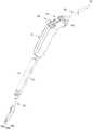
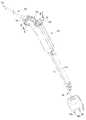
도 1a 및 도 1b는 본 발명의 실시예에 따른 외과수술용 의료장치를 서로 다른 방향에서 각각 도시한 사시도이다.
도 2는 도 1a의 분해사시도 및 부분 확대도이다.
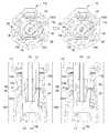
도 3은 도 1b의 절단선에 각각 기초하여 본 발명의 실시예에 따른 단전스위치의 작동상태를 각각 도시한 도면이다.
도 4는 본 발명의 실시예에 따른 조절부의 작동을 보이기 위한 작동상태도이다.
도 5는 본 발명의 실시예에 따른 바디부 및 외과처치부 간의 탈착결합과 삽입관의 상대이동을 보이기 위한 작동상태도이다.
도 6은 본 발명의 변형예에 따른 어댑터에 부설되는 지지부재의 작동을 도시한 도면이다.1A and 1B are perspective views each showing a surgical device for surgery according to an embodiment of the present invention in different directions.
2 is an exploded perspective view and a partially enlarged view of FIG. 1A.
Figure 3 is a view showing the operating state of the power cut-off switch according to an embodiment of the present invention, respectively based on the cutting line of Figure 1b.
4 is an operation state diagram for showing the operation of the adjustment unit according to an embodiment of the present invention.
5 is an operation state diagram for showing the relative movement of the insertion tube and the detachable coupling between the body portion and the surgical treatment unit according to an embodiment of the present invention.
6 is a view showing the operation of the support member attached to the adapter according to a modification of the present invention.
이하, 첨부된 도면을 참조하여 본 발명의 바람직한 실시예들을 상세하게 설명하면 다음과 같다. 다만, 본 발명을 설명함에 있어서, 이미 공지된 기능 혹은 구성에 대한 설명은, 본 발명의 요지를 명료하게 하기 위하여 생략하기로 한다.Hereinafter, preferred embodiments of the present invention will be described in detail with reference to the accompanying drawings. However, in describing the present invention, descriptions of already known functions or configurations will be omitted to clarify the gist of the present invention.
도 1a 및 도 1b는 본 발명의 실시예에 따른 외과수술용 의료장치를 서로 다른 방향에서 각각 도시한 사시도이고, 도 2는 도 1a의 분해사시도 및 부분 확대도이고, 도 3은 도 1b의 절단선에 각각 기초하여 본 발명의 실시예에 따른 단전스위치의 작동상태를 각각 도시한 도면이고, 도 4는 본 발명의 실시예에 따른 조절부의 작동을 보이기 위한 작동상태도이고, 도 5는 본 발명의 실시예에 따른 바디부 및 외과처치부 간의 탈착결합과 삽입관의 상대이동을 보이기 위한 작동상태도이고, 도 6은 본 발명의 변형예에 따른 어댑터에 부설되는 지지부재의 작동을 도시한 도면이다.1A and 1B are perspective views each showing a medical device for surgery in accordance with an embodiment of the present invention in different directions, FIG. 2 is an exploded perspective view and a partially enlarged view of FIG. 1A, and FIG. 3 is a cut of FIG. 1B It is a diagram showing the operating state of the power cut-off switch according to an embodiment of the present invention based on the line, respectively, Figure 4 is an operating state diagram for showing the operation of the adjustment unit according to an embodiment of the present invention, Figure 5 is the present invention It is an operation state diagram for showing the relative movement of the insertion tube and the detachable coupling between the body part and the surgical treatment part according to the embodiment, and FIG. 6 is a view showing the operation of the support member attached to the adapter according to the modification of the present invention.
발명의 설명 및 청구범위 등에서 방향을 지칭하는 상(위쪽), 하(아래쪽), 좌우(옆쪽 또는 측방), 전(정,앞쪽), 후(배,뒤쪽) 등은 권리의 한정의 용도가 아닌 설명의 편의를 위해서 도면 및 구성 간의 상대적 위치를 기준으로 정한 것으로, 이하에서 설명되는 각 방향은 이와 다르게 특별히 한정하는 경우를 제외하고, 이에 기초한 것이다.In the description and claims of the present invention, the upper (upper), lower (lower), left and right (side or side), front (front, front), rear (back, rear), etc., which refer to directions, are not intended to limit the use of rights. For convenience of description, it is determined based on the relative position between the drawings and the configuration, and each direction described below is based on this, except when otherwise specifically limited.
본 발명에 따른 외과수술용 의료장치(100)는, 최소 침습수술에 대한 적용의 용이성 및 안전성은 물론, 수술에 사용된 구성부품의 유지 관리상의 편의성과, 시술자에 의한 외과적 처치의 편의와 신속성 및 정밀성 등을 도모하기 위해 안출된 발명으로, 이를 통해 궁극적으로는 환자의 신속한 치료 및 회복이 이루어질 수 있게 된다.The
위와 같은 기능 내지 작용을 구현하기 위해, 본 발명에 따른 외과수술용 의료장치(100)는, 도면에 도시된 바와 같이 바디부(110), 외과처치부(120), 조절부(150), 전원연결부(160), 처치변환부(170) 및 단전스위치(180) 등을 포함하여 구성될 수 있다.In order to implement the above functions or functions, the
이하에서는 상술한 각 구성들에 대하여 구체적으로 설명하기로 한다.Hereinafter, each of the above-described components will be described in detail.
바디부(110)는 내부에 각종 부품들이 설치되는 공간이 마련되고 시술자가 손으로 파지하게 되는 구성요소로서, 그 설치공간에는 유체의 공급 및 흡인을 위한 공급관(112) 및 흡인관(114)과, 유체의 유량조절을 위한 조절부(150)와, 외부로부터 특정한 제어전원을 인가받는 전원연결부(160)가 각각 내설될 수 있다.The
이러한 바디부(110)는 시술자가 한 손으로 편안하고 손쉽게 파지할 수 있고, 파지한 상태에서 손으로부터의 이탈을 적절히 저감할 수 있는 굴곡이 외주면 일측에 형성된 것이라면 어떠한 형상이라도 무방하다.The
다만, 본 발명의 실시예에 따른 바디부(110)는, 도 1 및 도 2에 도시된 바와 같이 후술할 외과처치부(120)의 길이방향에 대하여 소정각도로 절곡된 형태 즉, 전체적으로 권총 형상으로 제작될 수 있는데, 이는 외과처치부(120)를 통한 신체 내 수술시 시술자의 손목이 과도하게 꺾이는 것을 방지하기 위함이다.However, the
이러한 형상의 바디부(110) 내측에는 결합돌기체(116)가 내설되는데, 결합돌기체(116)는 후술할 외과처치부(120)(구체적으로 어댑터(130))에 대하여 공급관(112), 흡인관(114) 및 전원연결부(160)가 각각 연결되도록 매개하는 한편, 외과처치부(120)와 바디부(110) 간의 상대회전 및 탈착결합이 가능해지도록 하기 위해 마련되는 구성요소이다.Inside the
구체적으로 결합돌기체(116)는, 도 2 내지 도 5 등에 도시된 바와 같이, 매니폴드(116a) 및 끼움부(116b) 등을 포함하는 일체형 구조로 이루어질 수 있다.Specifically, the
이때, 매니폴드(116a)는 바디부(110)에 내설된 상태로 공급관(112) 및 흡인관(114)과 각각 연통되는 한 쌍의 연결배관을 갖는 관체형상의 구성요소이다.At this time, the
그리고 끼움부(116b)는 단일한 관체로 이루어져 매니폴드(116a)와 연통되며 일체를 이룬 상태로 외과처치부(120)(구체적으로 어댑터(130)의 체결슬리브(134))와 끼움결합되는 한편, 어댑터(130)와 전원연결부(160) 간을 전기적으로 연결하기 위해 관통형성되는 단자접속공(116c)이 일측에 구비되는 구성요소이다.And the fitting portion (116b) is made of a single tube and communicates with the manifold (116a) and is integrally fitted with the surgical treatment unit 120 (specifically the fastening sleeve (134) of the adapter 130)) , It is a component that is provided on one side of the terminal connecting hole (116c) formed through to connect the
여기서 단자접속공(116c)은, 도 3(a) 및 (b)에 도시된 바와 같이, 후술할 전원연결부(160)와 연계접속된 처치변환부(170)(스위칭모듈)(및 단전스위치(180)의 접촉단자(182))를 통해 제공되는 제어전원이 관체형상의 끼움부(116b)를 관통하여 끼움부(116b) 내측에 결합된 어댑터(130)(구체적으로 패킹단자(134b))에 인가되도록 기능하게 된다.Here, the
또한, 단자접속공(116c)은, 후술할 단전스위치(180)의 접촉단자(182)와의 끼움결합을 통해 외과처치부(120)가 바디부(110)로부터 이탈 내지 분리되는 것을 방지하는 잠금기능을 수행하는 한편, 접촉단자(182)와의 끼움결합 해제를 통해 외과처치부(120)가 바디부(110)로부터 이탈 내지 분리되도록 하는 잠금해제기능을 수행하게 된다.In addition, the
즉, 위와 같은 단자접속공(116c)의 기능은 모두 후술할 접촉단자(182)의 진퇴(進退)작동과 상호 연동하여 이루어지게 되는 것이다.That is, all of the functions of the
상술한 매니폴드(116a), 끼움부(116b) 및 단자접속공(116c)은 절연성 엔지니어링 플라스틱을 소재로 일체로 사출성형되어 결합돌기체(116)를 이룰 수 있다.The manifold 116a, the
공급관(112)은 외부 유체공급장치(미도시)로부터 제공되는 유체 즉, 식염수 또는 인공체액이나 공기, 아르곤 가스 또는 마취 가스 등을 전달받아 후술할 외과처치부(120)에 공급하는 관체형상의 구성요소이다.The
이러한 공급관(112)의 일단부는 바디부(110)의 외측으로 노출되어 외부 유체공급장치(미도시)와 연통되고, 타단부는 결합돌기체(116)의 매니폴드(116a)와 연통되도록 결합될 수 있다.One end of the
그리고 흡인관(114)은 외부 유체공급장치(미도시)로부터 제공된 후 공급관(112)과 외과처치부(120)를 통해 소정의 목적을 위해 신체 내로 분사된 유체(식염수 또는 인공체액이나 공기, 아르곤 가스 또는 마취 가스 등)를 흡인하여 외부로 배출하는 관체형상의 구성요소이다.And the
이러한 흡인관(114)의 일단부는 바디부(110)의 외측으로 노출되어 외부 유체공급장치(미도시)나 별도의 저장탱크(미도시)와 연통되고, 타단부는 결합돌기체(116)의 매니폴드(116a)와 연통되도록 결합될 수 있다.One end of the
외과처치부(120)는, 신체 내 환부로 삽입되어 절개, 지혈(응고) 등과 같은 외과적 처치와, 유체공급장치(미도시)로부터 제공되는 유체의 분사 및 흡입을 통한 환부 주변의 세정 등을 함께 수행하게 되는 구성요소로서, 전체적으로 하나의 얇고 긴 관체형상으로 제작되어 상술한 바디부(110)에 탈착결합될 수 있다.The
상술한 바와 같은 기능 내지 작용을 수행하기 위해, 본 발명의 실시예에 따른 외과처치부(120)는, 도 1 내지 도 5에 도시된 바와 같이 어댑터(130) 및 삽입관(140) 등을 포함하여 구성될 수 있다.In order to perform the functions or functions as described above, the
구체적으로, 어댑터(130)는, 도전성 소재로 제작된 관체형상으로 되어 외부 전원장치(미도시)로부터 공급되는 제어전원을 후술할 전원연결부(160), 처치변환부(170) 및 끼움부(116b)의 단자접속공(116c)을 통해 순차로 인가받아 신체 내 환부에 흘림으로써 절개, 지혈(응고) 등과 같은 외과적 처치를 수행하는 한편, 내부에 관통형성된 중공(131)을 통해 공급관(112) 및 흡인관(114)과 각각 연통되어 유체의 분사와 흡인 기능을 각각 수행하는 구성요소이다.Specifically, the
이러한 어댑터(130)는, 신체 내 환부에 대한 제어전원의 흘림을 통한 외과적 처치가 환부에 대한 지향성을 갖고 정밀하게 수행될 수 있도록, 그 일단부에는 외과처리용 전극팁(132)이 돌출형성될 수 있으며, 도 2, 도 5 및 도 6에 도시된 바와 같이 안쪽으로 절곡된 형태일 수 있다.In the
이때, 도전성 어댑터(130)를 통해 환부에 흘려지는 선택된 전기에너지(대략 300KHz ~ 3MHz 범위) 즉, 소정의 제어전원에 의해 이루어지는 절개, 지혈(응고) 등과 같은 외과적 처치와 관련된 기술적 내용이나 원리는 이미 공지된 사항이므로 구체적인 설명은 생략하기로 한다.At this time, the selected electrical energy (approximately 300KHz ~ 3MHz range) that flows to the affected area through the
반면에 전극팁(132)이 형성된 어댑터(130)의 반대편 타단부에는 체결슬리브(134)가 구비될 수 있다. 여기서 체결슬리브(134)는, 어댑터(130)를 내측에 수용하도록 일체로 결합된 상태에서 상술한 결합돌기체(116)의 끼움부(116b)와의 탈착결합 및 바디부(110)에 대한 외과처치부(120)의 상대회전 등을 가능하게 하는 한편, 끼움부(116b)의 단자접속공(116c)을 통해 제어전원이 어댑터(130)에 인가되도록 매개하는 구성요소이다.On the other hand, a
구체적으로 체결슬리브(134)는, 위와 같은 기능 내지 작용의 구현을 위해, 도 3 및 도 5에 도시된 바와 같이, 절연몸체(134a) 및 패킹단자(134b) 등을 포함하여 구성될 수 있다.Specifically, the
여기서 절연몸체(134a)는, 절연성 엔지니어링 플라스틱을 소재로 어댑터(130)의 타단부 측을 내부에 수용하도록 결합되어 끼움부(116b)에 끼워지는 원통형의 구성요소로서, 후술할 노브체(142)의 저지턱(142b)에 의해 이탈이 방지되면서 노브체(142)에 대한 슬라이딩을 안내하도록 단부 외연이 확장형성된 슬라이드판(134a1)과, 노브체(142)의 가이드돌기(142a)에 끼워져 노브체(142)의 슬라이딩을 안내하는 가이드홈(134a2)이 슬라이드판(134a1)의 일측에 형성될 수 있다.Here, the insulating
패킹단자(134b)는, 상술한 절연몸체(134a)와 접하며 어댑터(130)의 끝단을 내부에 수용하도록 결합되어 끼움부(116b)에 밀폐된 상태로 끼워지는 원통형의 구성요소로서, 어댑터(130)와 통전이 이뤄지도록 도전성 소재로 제작되고, 외주면 일측에는 끼움부(116b)와의 밀폐결합을 위한 하나 이상의 오링(134b1)이 구비되며, 단자접속공(116c)과 인접하는 외주 둘레에는 후술할 접촉단자(182)가 끼워져 접속되는 링형의 체결홈(134b2)이 구비될 수 있다.The packing terminal 134b is a cylindrical component that is in contact with the above-described
이때, 오링(134b1)은 상술한 매니폴드(116a)를 통해 양방향 유동하는 유체가 누출되는 것을 방지하고, 끼움부(116b)와 체결슬리브(134) 간의 결합상태가 견고하게 유지되게 하는 기능을 수행하게 된다.At this time, the O-ring (134b1) prevents the fluid flowing in both directions through the above-described manifold (116a) leaks, and performs a function of maintaining a tightly coupled state between the fitting portion (116b) and the fastening sleeve (134) Is done.
위와 같은 구성들로 일체화된 체결슬리브(134)와 결합돌기체(116)의 끼움부(116b) 간의 끼움 구조로 인해 결국, 도 5에 도시된 바와 같이 외과처치부(120)는 바디부(110)에 대하여 원활하게 탈착결합되며 상대회동될 수 있는 것이고, 어댑터(130)에 대한 삽입관(140)의 상대이동이 원활하게 이루어질 수 있게 된다.Due to the fitting structure between the
한편, 본 발명의 변형예에 따른 어댑터(130)는, 도 6에 도시된 바와 같이 전극팁(132)이 노출되게 삽입관(140)이 상대이동(후퇴)하는 경우, 전극팁(132)을 마주보는 위치에서 노출과 함께 탄성변형되는 절연재질의 지지부재(135)를 더 포함할 수 있다. 이러한 지지부재(135)에 의해 환부에 대한 전극팁(132)의 위치가 안정적으로 이격지지될 수 있게 된다.On the other hand, the
상술한 바와 같은 지지부재(135)는, 가공성 내지 성형성, 내충격성, 내열성, 내약품성, 절연성 등이 우수하고, 뛰어난 상용성으로 인해 PC(폴리카보네이트)나 폴리우레탄 등과 혼합 사용되어 필요한 탄성을 확보할 수 있는 ABS(acrylonitrile-butadiene-styrene)수지 또는 치수 안정성, 난연성, 절연성, 내마모성 등이 우수하고, 역시 뛰어난 상용성으로 인해 필요한 탄성을 확보할 수 있는 PBT(polybutyrene terephthalate resin)수지 등을 소재로 제작되어 어댑터(130) 단부에 고정결합될 수 있다.The
보다 구체적으로 지지부재(135)는, 일례로서 도 6의 (a)에 도시된 바와 같이 마치 총열의 지면거치를 위한 양각대처럼, 삽입관(140)으로부터 노출시 전극팁(132)과 멀어지는 방향으로 탄성변형되면서 단부가 서로 벌어지는 한 쌍의 받침로드(135a)로 이루어질 수 있으며, 이때, 받침로드(135a)의 각 단부에는, 견고한 위치유지를 위한 톱니형 고정부재(135b)가 형성될 수 있다.More specifically, the
이러한 일례에 따른 구조로 이루어진 지지부재(135)(받침로드(135a) 및 고정부재(135b))를 통해 전극팁(132)의 위치가 환부 주변에 안정적으로 이격지지됨에 따라 시술자는 흔들림 없이 환부에 대한 외과적 처치를 정확하게 수행할 수 있게 된다.As the position of the
또한, 지지부재(135)는, 또 다른 일례로서 도 6의 (b)에 도시된 바와 같이, 삽입관(140)으로부터 노출시 전극팁(132)과 멀어지는 방향으로 탄성변형되는 지지로드(135c)로 이루어질 수 있으며, 지지로드(135c)의 단부에는 마치 마개처럼, 지지로드(135c)가 삽입관(140)에 수납되는 경우 삽입관(140)의 단부를 폐쇄하기 위한 막음부재(135d)가 형성될 수 있다.In addition, the
이러한 또 다른 일례에 따른 구조로 이루어진 지지부재(135)(지지로드(135c) 및 막음부재(135d))를 통해 전극팁(132)의 위치가 안정적으로 이격지지됨에 따라 시술자는 흔들림 없이 환부에 대한 외과적 처치를 정확하게 수행할 수 있음은 물론, 막음부재(135d)를 통해 외과처치부(120)의 신체 내 삽입시 전극팁(132)에 의한 전기적 안전사고 및 신체 내부조직의 손상 내지 훼손 등이 보다 완벽하게 방지될 수 있다.As the position of the
삽입관(140)은, 상술한 어댑터(130)를 내부에 수용할 수 있는 절연성 소재의 관체로 이루어져 어댑터(130)에 인가된 제어전원이 외부로 누전되는 것을 차폐할 수 있는 구조나 형태로 이루어진 것이라면 충분하다.The
다만, 본 발명의 실시예에 따른 삽입관(140)은, 도 2 및 도 3b 등에 도시된 바와 같이 상술한 체결슬리브(134)에 대하여 슬라이딩이동이 가능하도록 체결슬리브(134)를 수용하는 노브체(142)와 일체로 이루며 결합될 수 있다.However, the
이때, 노브체(142)는 외주면에 시술자가 손가락으로 용이하게 파지할 수 있는 함몰부가 방사형태로 배치된 원추형상으로 이루어질 수 있는데, 이러한 형상으로 인해 바디부(110)에 대한 외과처치부(120)의 상대회전시 시술자의 편의가 도모될 수 있다.At this time, the
그리고 체결슬리브(134)를 수용하게 되는 노브체(142)의 내측에는, 도 5에 도시된 바와 같이 슬라이드판(134a1)에 형성된 가이드홈(134a2)에 끼워져 노브체(142) 및 삽입관(140)의 슬라이딩을 안내하는 상보적 단면형상의 가이드돌기(142a)가 구비됨에 따라 삽입관(140)의 어댑터(130)에 대한 상대이동이 정확하고 원활하게 안내될 수 있게 된다.And inside the
또한, 체결슬리브(134)를 수용하는 노브체(142)의 단부에는, 도 5에 도시된 바와 같이, 슬라이드판(134a1)의 이탈을 방지하기 위해 안쪽으로 돌출된 저지턱(142b)이 형성되고, 저지턱(142b)과 접촉하게 되는 끼움부(116b)의 외주면에는 노브체(142) 및 삽입관(140)의 슬라이딩을 단계별로 이루어지게 하거나 제한하는 하나 이상의 슬라이드제한돌기(116b1)가 링형태로 이격되며 돌출형성될 수 있다.In addition, at the end of the
이렇게 삽입관(140)과 일체로 결합된 노브체(142)와 체결슬리브(134) 간에 이루어지는 상호작동을 통해, 어댑터(130)의 전극팁(132)은 삽입관(140) 내로 정확하게 수납되고 인출될 수 있게 되므로, 외과처치부(120)의 신체 내 삽입시 뾰족하게 돌출된 전극팁(132)에 의한 전기적 안전사고 및 신체 내부조직의 손상 내지 훼손 등이 원천적으로 방지될 수 있게 된다.Through the interaction between the
이상에서 살펴본 구조 즉, 하나의 얇고 긴 이중 관체형상으로 제작되어 상술한 바디부(110)(110)에 대하여 탈착결합 및 상대회전하고, 전극팁(132)이 삽입관(140) 내부에 선택적으로 수납되는 외과처치부(120)(120)로 인해, 복강경 수술과 같은 신체 내 환부에 대한 최소 침습술에 대한 용이한 적용, 장치의 유지관리상의 편의성 및 수술의 편의성 등이 도모될 수 있게 된다.The structure as described above, that is, manufactured in one thin and long double tube shape, is detachably coupled and rotated relative to the above-described
또한, 이러한 외과처치부(120)를 통해 신체 내 환부에 대한 절개, 지혈(응고) 등과 같은 다양한 외과적 처치 및 외부에서 제공되는 유체의 분사 및 흡입을 통한 환부 주변의 세정 등이 함께 수행될 수 있게 됨에 따라 정밀한 외과적 처치가 불편함 없이 용이하게 이루어질 수 있게 되는 것이다.In addition, various surgical procedures such as incision, hemostasis (coagulation), etc. on the affected part of the body through the
조절부(150)는, 상술한 공급관(112) 및 흡인관(114)의 일측에 마련되어 분사되거나 흡인되는 유체의 유량을 조절하는 구성요소로서, 연질의 공급관(112)과 흡인관(114) 일측을 가압하여 유체의 유동을 개방 또는 폐쇄하며 유체의 양을 조절하는 방식 내지 구조로 이루어진 것이라면, 어떠한 것이라도 무방하다.The
다만, 본 발명의 실시예에 따른 조절부(150)는, 도 2 및 도 4에 도시된 바와 같이, 한 쌍의 버튼부(152a,152b), 가압로드(154a,154b) 및 스프링(156a,156b) 등을 포함하여 구성될 수 있는데, 이러한 구성들은 모두 상술한 결합돌기체(116)와 별도로 형성되어 결합돌기체(116)에 체결되거나 또는 결합돌기체(116)와 일체로 형성된 관거치브라켓(153)에 장착될 수 있다.However, the
이때, 관거치브라켓(153)은 매니폴드(116a)와의 체결과 후술할 가압로드(154a,154b)에 의한 가압작동이 안정적으로 이루어지도록 하기 위해 공급관(112)과 흡인관(114)에 의해 관통된 상태로 각각을 고정 지지하게 된다.At this time, the
한 쌍의 버튼부(152a,152b)는, 바디부(110)에 대하여 상하로 각각 이동가능하게 돌출 설치되어 시술자의 손가락에 의한 외력이 직접 작용하게 되는 구성요소로서, 그 하단부 각각은 공급관(112) 및 흡인관(114)의 하면을 가압하도록 이루어진 후술할 가압로드(154a,154b)의 일단부와 접촉하여 시술자의 외력을 전달되게 된다.The pair of
한 쌍의 가압로드(154a,154b)는, 공급관(112) 및 흡인관(114)을 각각 선택적으로 가압 또는 가압해제하기 위해 마련된 막대형상의 구성요소로서, 일단부는 바디부(110) 내부 즉, 구체적으로는 관거치브라켓(153) 일측에 회동가능하게 설치되며, 타단부는 버튼부(152a,152b)의 하단부와 접하도록 구비될 수 있다.The pair of
이때, 가압로드(154a,154b)의 중앙부에는 관거치브라켓(153)에 의해 타면이 지지된 공급관(112) 또는 흡인관(114)의 반대쪽 일면의 일지점을 정확히 가압하기 위한 가압돌기가 상방으로 돌출형성될 수 있으며, 이로 인해 가압로드(154a,154b)는 버튼부(152a,152b)의 상하방 이동에 따라 회동하며 공급관(112)과 흡인관(114)을 각각 정확하게 가압차폐할 수 있게 된다.At this time, in the central portion of the pressure rods (154a, 154b), the pressure protrusion for accurately pressing a point on one side of the
스프링(156a,156b)은, 버튼부(152a,152b)의 상방 이동과 가압로드(154a,154b)의 가압차폐작동을 각각 강제하기 위해 탄성력을 발휘하는 한 쌍의 구성요소로서, 구체적으로 관거치브라켓(153) 일측에 대하여 회동가능하게 축결합된 가압로드(154a,154b)와 관거치브라켓(153) 사이에서 가압로드(154a,154b)가 상방으로 회동하도록 지지되며 설치된 토션스프링(156a,156b)으로 구현될 수 있다.The
한편, 조절부(150)는, 도 4에 도시된 바와 같이, 한 쌍의 버튼부(152a,152b) 사이에 구비되어 적어도 어느 하나의 버튼부(152a,152b)가 눌려진 상태에서 고정되도록 하는 고정유지부(158)를 더 포함할 수 있다.On the other hand, the
이러한 고정유지부(158)는 도 2, 도 4 및 도 5에 도시된 바와 같이, 한 쌍의 버튼부(152a,152b) 사이에 얇은 벽형태로 형성된 격벽(158a)과, 격벽(158a)의 상단부를 관통하여 눌려진 버튼을 고정하는 고정핀(158b)으로 구성될 수 있는데 이때, 격벽(158a)은 상술한 결합돌기체(116)와 일체로 형성될 수 있다.As shown in FIGS. 2, 4, and 5, the fixed holding
고정유지부(158)를 통해 한 쌍의 버튼부(152a,152b)가 눌림상태로 고정됨으로 인해 공급관(112) 및 흡인관(114)의 개방이 유지될 수 있게 됨에 따라 제품 완성 후 관체 내부에 대한 완벽한 멸균 작업이 가능하고 후속 포장작업이 멸균상태로 이루어질 수 있게 된다.As the pair of
처치변환부(170)는, 전원연결부(160)와 연계된 상태로 바디부(110)에 구비되어 전극팁(132)의 환부에 대한 외과적 처치를 선택적으로 절환시키는 구성요소로서, 이로 인해 시술자는 이격된 장소에 설치된 외부 전원장치(미도시)를 직접 조작하지 않고도 본 발명에 따른 의료장치(100)를 통해 적절하고 신속한 외과적 처치를 수행할 수 있게 된다.The
본 발명의 실시예에 따른 처치변환부(170)는, 도 2 등에 도시된 바와 같이 회로판(174) 및 시소버튼(172) 등으로 구성된 스위칭모듈로 구현될 수 있다.The
여기서 회로판(174)은, 지혈, 응고, 절개에 대응하는 전기에너지를 갖는 적어도 2개 이상의 제어전원이 개별적으로 인가된 전선들(160a,160b,160c, 전원연결부(160))이 각각 구별되게 접속되고 후술할 단전스위치(180)(구체적으로 판스프링(184) 측)와 전기적으로 연결되는 구성요소이다.Here, the
그리고 시소버튼(172)은, 소정범위 내에서 다단으로 회전하며 접속된 전선들(160a,160b,160c) 중 어느 하나를 선택적으로 어댑터(130)(구체적으로 후술할 접촉단자(182))에 통전시키는 구성요소이다.In addition, the
이러한 스위칭모듈의 절환조작(스위칭 조작)을 통해 지혈, 응고, 절개 및 정지 모드 중 적어도 2 이상의 모드에 각각 대응하는 제어전원이 선택되어 어댑터(130)에 인가될 수 있게 되는 것이다.Through the switching operation (switching operation) of the switching module, control power corresponding to at least two or more of hemostasis, coagulation, incision, and stop modes is selected and applied to the
단전스위치(180)는, 상술한 스위칭모듈에 접속되어 인가받은 제어전원이 어댑터(130)에 선택적으로 전달되도록 하는 전원단속기능과, 외과처치부(120)가 바디부(110)로부터 분리되는 것을 방지하는 잠금기능과, 결합된 외과처치부(120)가 바디부(110)에서 분리되게 하는 잠금해제 기능을 동시에 수행하는 구성요소이다.The
이러한 기능 내지 작용의 구현을 위해, 본 발명의 실시예에 따른 단전스위치(180)는, 도 2 및 도 3에 도시된 바와 같이 접촉단자(182), 판스프링(184) 및 누름단추(186) 등을 포함하여 구성될 수 있다.For the implementation of these functions or actions, the
먼저, 접촉단자(182)는, 바디부(110) 내측에서 어댑터(130)를 향해 진퇴(進退)하며 어댑터(130)에 선택적으로 접속하게 되는 도전성의 구성요소로서, 후술할 누름단추(186) 일측에서 내측으로 돌출형성되어 누름단추(186)에 가해지는 외력에 따라 끼움부(116b)의 단자접속공(116c)을 관통하며 전진과 후퇴작동을 하게 된다.First, the
이러한 접촉단자(182)는, 도 3의 (a)에 도시된 바와 같이, 어댑터(130)와 결합된 도전성의 패킹단자(134b)가 끼움부(116b)에 완전히 끼워진 상태에서 누름단추(186)에 외력이 가해지지 않게 되면, 후술할 판스프링(184)의 탄성력이 작용하게 되는 결과 단자접속공(116c)을 관통하여 패킹단자(134b)와 강제 접속 내지 통전상태를 이루게 된다.The
이로 인해 처치변환부(170)(스위칭모듈)에 접속된 제어전원은 접촉단자(182), 패킹단자(134b) 및 어댑터(130)를 거쳐 결국, 전극팁(132)에 인가되어 처치변환부(170)에 의해 선택된 외과적 처치가 수행될 수 있게 된다.Due to this, the control power connected to the treatment conversion unit 170 (switching module) is applied to the
또한, 접촉단자(182)가 패킹단자(134b)의 체결홈(134b2)에 끼워진 상태여서 바디부(110)로부터 외과처치부(120)의 분리가 방지되는 잠금상태를 유지함에 따라 안정적인 외과적 처치가 이루어지게 된다.In addition, a stable surgical treatment as the
반면에 도 3의 (b)에 도시된 바와 같이, 어댑터(130)와 결합된 도전성의 패킹단자(134b)가 끼움부(116b)에 완전히 끼워진 상태에서 누름단추(186)에 외력이 가해지게 되면, 후술할 판스프링(184)이 외력에 의해 탄성변형되며 눌려짐에 따라 접촉단자(182)는, 패킹단자(134b)와의 접속이 끊어지게 되어 처치변환부(170)에 의해 선택된 외과적 처치는 중단되게 된다.On the other hand, as shown in (b) of FIG. 3, when an external force is applied to the
또한, 접촉단자(182)는 패킹단자(134b)의 체결홈(134b2)으로부터 이탈되는 관계상, 외과처치부(120)는 바디부(110)로부터 분리가 가능한 잠금해제상태에 놓이게 됨에 따라 외과처치부(120)의 교체 등이 손쉽게 이루어질 수 있게 된다.In addition, since the
판스프링(184)은, 접촉단자(182)에서 연장형성되어 스위칭모듈에 접속되는 한편, 접촉단자(182)가 어댑터(130)에 접속되도록 탄성력을 발휘하는 도전성의 구성요소로서, 전체적으로 'ㄷ' 자 형상으로 이루어져 일단부가 접촉단자(182)와 연결된 상태에서 타단부는 바디부(110)의 내측면에 지지된 형태로 탄성력을 발휘하게 된다.The
누름단추(186)는, 일측에서 내측으로 돌출형성된 접촉단자(182)와 어댑터(130) 간을 선택적으로 단속시키는 구성요소로서, 끼움부(116b)의 외주면을 둘러싸는 링형태로 구비되어 일단부가 바디부(110)의 외측으로 돌출되고 타단부가 접촉단자(182)와 결합되어 이루어지게 된다.The
위와 같은 구조로 이루어진 단전스위치(180)에 의한 전원단속기능을 통해 전기적 안전사고 등의 위험이 더욱 저감될 수 있고, 수술중 의도하지 않은 외과처치부(120)의 분리가 방지될 수 있어 시술자는 보다 안정적으로 외과적 처치를 수행할 수 있게 되는 것이다.Through the power interruption function by the
앞에서, 본 발명의 특정한 실시예가 설명되고 도시되었지만 본 발명은 기재된 실시예에 한정되는 것이 아니고, 본 발명의 사상 및 범위를 벗어나지 않고 다양하게 수정 및 변형할 수 있음은 이 기술의 분야에서 통상의 지식을 가진 자에게 자명한 일이다. 따라서, 그러한 수정예 또는 변형예들은 본 발명의 기술적 사상이나 관점으로부터 개별적으로 이해되어서는 안 되며, 변형된 실시예들은 본 발명의 특허청구범위에 속한다 하여야 할 것이다.In the foregoing, although specific embodiments of the present invention have been described and illustrated, the present invention is not limited to the described embodiments, and it is common knowledge in the art that various modifications and modifications can be made without departing from the spirit and scope of the present invention. It is obvious to those who have it. Therefore, such modifications or variations should not be individually understood from the technical spirit or viewpoint of the present invention, and the modified embodiments should belong to the claims of the present invention.
100: 외과수술용 의료장치110: 바디부
112: 공급관114: 흡인관
116: 결합돌기체116a: 매니폴드
116b: 끼움부116b1: 슬라이드제한돌기
116c: 단자접속공120: 외과처치부
130: 어댑터131: 중공
132: 전극팁134: 체결슬리브
134a: 절연몸체134a1: 슬라이드판
134a2: 가이드홈134b: 패킹단자
134b1: 오링134b2: 체결홈
135: 지지부재135a: 받침로드
135b: 고정부재135c: 지지로드
135d: 막음부재140: 삽입관
142: 노브체142a: 가이드돌기
142b: 저지턱150: 조절부
152a,152b: 버튼부153: 관거치브라켓
154a,154b: 가압로드156a,156b: 스프링
158: 고정유지부158a: 격벽
158b: 고정핀160: 전원연결부
160a,160b,160c: 제1,2,3 전선170: 처치변환부(스위칭모듈)
172: 시소버튼174: 회로판
180: 단전스위치182: 접촉단자
184: 판스프링186: 누름단추100: surgical device for surgery 110: body part
112: supply pipe 114: suction pipe
116: engaging
116b: fitting portion 116b1: slide restriction projection
116c: Terminal connecting hole 120: Surgical treatment unit
130: adapter 131: hollow
132: electrode tip 134: fastening sleeve
134a: insulated body 134a1: slide plate
134a2: guide
134b1: O-ring 134b2: Fastening groove
135:
135b: Fixing
135d: blocking member 140: insertion tube
142:
142b: low jaw 150: adjusting portion
152a, 152b: Button section 153: Tube bracket
154a,154b:
158: fixed holding
158b: fixing pin 160: power connection
160a, 160b, 160c: first, second, and third wires 170: treatment conversion unit (switching module)
172: seesaw button 174: circuit board
180: power switch 182: contact terminal
184: leaf spring 186: push button
Claims (9)
Translated fromKorean상기 바디부에 탈착결합되며 상기 전원연결부, 공급관 및 흡인관과 각각 연결되고 단부에 전극팁이 돌출형성된 도전성의 중공형 어댑터와, 상기 어댑터를 내부에 수용한 상태로 상대이동하며 상기 전극팁을 선택적으로 내부에 수납하는 삽입관을 포함하여 신체 내 환부로 삽입되는 외과처치부; 및
상기 전원연결부와 연계된 상태로 상기 바디부에 구비되어 상기 전극팁의 환부에 대한 외과적 처치를 선택적으로 절환시키는 처치변환부를 포함하고,
상기 처치변환부는,
상기 전원연결부에 접속되어, 지혈, 응고, 절개 및 정지 모드 중 적어도 2 이상의 모드에 각각 대응하는 제어전원이 선택되도록 절환작동하는 스위칭모듈로 이루어진 것을 특징으로 하는 외과수술용 의료장치.A supply pipe and a suction pipe for supplying and aspirating the fluid, a control portion for adjusting the flow rate of the fluid, and a body portion to which the operator is gripped by providing a power connection unit for receiving external power;
A conductive hollow adapter detachably coupled to the body portion, connected to the power connection portion, the supply pipe and the suction pipe, and having an electrode tip protruding at an end, and a relative movement while receiving the adapter therein and selectively moving the electrode tip A surgical treatment part inserted into the affected part of the body, including an insertion tube accommodated therein; And
It is provided in the body portion in a state associated with the power connection portion includes a treatment conversion unit for selectively switching the surgical treatment for the affected area of the electrode tip,
The treatment conversion unit,
And a switching module connected to the power connection unit and configured to switch to control power corresponding to at least two of hemostatic, coagulation, incision, and stop modes, respectively.
상기 외과수술용 의료장치는,
상기 스위칭모듈에 접속되어 인가받은 제어전원이 상기 어댑터에 선택적으로 전달되도록 하기 위해, 상기 바디부 일측에는 단전스위치가 더 구비되는 것을 특징으로 하는 외과수술용 의료장치.According to claim 1,
The surgical device for surgery,
A medical device for surgery, characterized in that a power failure switch is further provided on one side of the body part so as to be selectively transmitted to the adapter by being connected to the switching module.
상기 단전스위치는,
상기 바디부 내측에서 상기 어댑터를 향해 진퇴하며 상기 어댑터에 선택적으로 접속하는 접촉단자와, 상기 접촉단자에서 연장형성되어 상기 스위칭모듈에 접속되고 상기 접촉단자가 상기 어댑터에 접속되도록 탄성력을 발휘하는 판스프링과, 일단부가 상기 바디부의 외측으로 돌출되고 타단부가 상기 접촉단자에 결합되어 상기 접촉단자와 상기 어댑터 간을 선택적으로 단속시키는 누름단추를 포함하는 것을 특징으로 하는 외과수술용 의료장치.According to claim 3,
The power failure switch,
A plate spring that moves forward from the inside of the body toward the adapter and selectively connects to the adapter, extends from the contact terminal, is connected to the switching module, and exerts an elastic force so that the contact terminal is connected to the adapter. And, One end is projected to the outside of the body portion and the other end is coupled to the contact terminal Medical device for surgery, characterized in that it comprises a push button to selectively interrupt between the contact terminal and the adapter.
상기 조절부는,
상기 바디부에 대하여 각각 상하로 이동가능하게 구비된 한 쌍의 버튼부;
일단부가 상기 바디부 내부에 회동가능하게 설치되고, 타단부가 상기 버튼부의 단부와 접하도록 구비되어 상기 버튼부의 상방 이동에 따라 회동하며 상기 공급관과 상기 흡인관을 각각 가압차폐하는 한 쌍의 가압로드; 및
상기 바디부 내부에 설치되어 상기 버튼부의 상방 이동과 상기 가압로드의 가압차폐작동을 강제하는 한 쌍의 스프링을 포함하는 것을 특징으로 하는 외과수술용 의료장치.According to claim 1,
The adjustment unit,
A pair of button portions, each of which is movable up and down relative to the body portion;
A pair of pressure rods, one end of which is rotatably installed inside the body, and the other end of which is in contact with the end of the button, rotates according to the upward movement of the button and pressurizes and shields the supply pipe and the suction pipe, respectively; And
And a pair of springs installed inside the body portion to force upward movement of the button portion and pressurized shielding operation of the pressurized rod.
상기 조절부는,
한 쌍의 상기 버튼부 사이에 구비되어 적어도 어느 하나의 상기 버튼부가 눌려진 상태에서 고정되도록 하는 고정유지부를 더 포함하는 것을 특징으로 하는 외과수술용 의료장치.The method of claim 5,
The adjustment unit,
A medical device for surgery, characterized in that it further comprises a fixed holding portion which is provided between the pair of button portions so that at least one of the button portions is fixed in a pressed state.
상기 바디부 및 상기 외과처치부 간의 탈착결합은,
상기 바디부에 내설되어 상기 공급관 및 흡인관과 각각 연통되는 매니폴드 및 상기 매니폴드에 연통된 상태로 돌출형성되는 끼움부를 포함하는 결합돌기체와, 상기 어댑터와 결합된 상태에서 상기 끼움부 내측에 끼움결합되는 체결슬리브를 통해 이루어지는 것을 특징으로 하는 외과수술용 의료장치.According to claim 1,
The detachable coupling between the body portion and the surgical treatment portion,
A coupling protrusion body installed in the body portion and including a manifold communicating with the supply pipe and the suction pipe, respectively, and a fitting portion protrudingly formed in a state in communication with the manifold, and being fitted inside the fitting portion while being coupled with the adapter. Medical device for surgery, characterized in that through a fastening sleeve to be combined.
상기 어댑터에 대한 상기 삽입관의 상대이동은,
상기 체결슬리브에 대한 제한된 슬라이딩이 가능하도록 상기 체결슬리브를 수용하며 상기 삽입관과 결합된 노브체를 통해 이루어지는 것을 특징으로 하는 외과수술용 의료장치.The method of claim 7,
The relative movement of the insertion tube with respect to the adapter,
Medical device for surgery, characterized in that it is made through a knob body coupled with the insertion tube and accommodates the fastening sleeve to enable a limited sliding relative to the fastening sleeve.
상기 어댑터는,
상기 전극팁이 노출되게 상기 삽입관이 상대이동하는 경우,
환부에 대한 상기 전극팁의 위치가 안정적으로 이격지지되도록, 상기 전극팁을 마주보는 위치에서 노출과 함께 탄성변형되는 절연재질의 지지부재를 더 포함하는 것을 특징으로 하는 외과수술용 의료장치.
According to claim 1,
The adapter,
When the insertion tube is moved relative to expose the electrode tip,
And a support member made of an insulating material elastically deformed with exposure at a position facing the electrode tip so that the position of the electrode tip relative to the affected area is stably spaced apart.
Priority Applications (4)
| Application Number | Priority Date | Filing Date | Title |
|---|---|---|---|
| KR1020180056123AKR102136319B1 (en) | 2018-05-16 | 2018-05-16 | Medical devices for surgical operations |
| EP19173623.0AEP3569175A1 (en) | 2018-05-16 | 2019-05-09 | Medical device for surgical operation |
| JP2019090647AJP6814840B2 (en) | 2018-05-16 | 2019-05-13 | Medical equipment for surgery |
| US16/413,951US20190350636A1 (en) | 2018-05-16 | 2019-05-16 | Medical devices for surgical operations |
Applications Claiming Priority (1)
| Application Number | Priority Date | Filing Date | Title |
|---|---|---|---|
| KR1020180056123AKR102136319B1 (en) | 2018-05-16 | 2018-05-16 | Medical devices for surgical operations |
Publications (2)
| Publication Number | Publication Date |
|---|---|
| KR20190131354A KR20190131354A (en) | 2019-11-26 |
| KR102136319B1true KR102136319B1 (en) | 2020-07-21 |
Family
ID=66476553
Family Applications (1)
| Application Number | Title | Priority Date | Filing Date |
|---|---|---|---|
| KR1020180056123AActiveKR102136319B1 (en) | 2018-05-16 | 2018-05-16 | Medical devices for surgical operations |
Country Status (4)
| Country | Link |
|---|---|
| US (1) | US20190350636A1 (en) |
| EP (1) | EP3569175A1 (en) |
| JP (1) | JP6814840B2 (en) |
| KR (1) | KR102136319B1 (en) |
Cited By (1)
| Publication number | Priority date | Publication date | Assignee | Title |
|---|---|---|---|---|
| KR102864600B1 (en) | 2022-11-04 | 2025-09-25 | 주식회사 티플랜트 | Medical device for laparoscopic surgery |
Families Citing this family (4)
| Publication number | Priority date | Publication date | Assignee | Title |
|---|---|---|---|---|
| CN112618005B (en)* | 2020-12-28 | 2022-03-18 | 广州保瑞医疗技术有限公司 | Electrocoagulation cutter |
| CN112716580B (en)* | 2021-01-06 | 2022-06-28 | 李珊 | Surgical paronychia treatment machine and using method thereof |
| KR102574347B1 (en)* | 2021-06-24 | 2023-09-01 | 김철중 | Hand-controlled surgical electrode device |
| KR102576658B1 (en)* | 2023-02-21 | 2023-09-08 | 주식회사 아모스팜 | A Hand Regulating Type of a Multi Electrical Surgery Tool |
Citations (3)
| Publication number | Priority date | Publication date | Assignee | Title |
|---|---|---|---|---|
| JP3187828B2 (en) | 1990-05-11 | 2001-07-16 | アプライド メディカル リソーセス コーポレイション | Electrosurgical electrode |
| JP2006341066A (en)* | 2005-05-13 | 2006-12-21 | Olympus Medical Systems Corp | Medical treatment tool |
| JP2012090999A (en) | 2005-12-12 | 2012-05-17 | Covidien Ag | Laparoscopic apparatus for performing electrosurgical procedure |
Family Cites Families (9)
| Publication number | Priority date | Publication date | Assignee | Title |
|---|---|---|---|---|
| JP3115902B2 (en)* | 1991-03-22 | 2000-12-11 | オリンパス光学工業株式会社 | Surgical handpiece |
| US5830214A (en)* | 1994-11-08 | 1998-11-03 | Heartport, Inc. | Fluid-evacuating electrosurgical device |
| KR19990028365A (en)* | 1995-06-23 | 1999-04-15 | 니겔 마크 고블 | Electrosurgical surgical instruments |
| US5609573A (en)* | 1996-02-28 | 1997-03-11 | Conmed Corporation | Electrosurgical suction/irrigation instrument |
| KR100389006B1 (en) | 2000-05-30 | 2003-06-25 | 이희영 | Searching and operating device of bleeding point comprising air brush |
| CN103271766B (en)* | 2012-08-24 | 2015-08-26 | 苏州信迈医疗器械有限公司 | A device for mapping and ablation of renal nerves located on the distribution of renal arteries |
| KR101359475B1 (en)* | 2011-11-30 | 2014-03-07 | 이메드 주식회사 | Surgical surgical device |
| US20150112335A1 (en)* | 2013-10-18 | 2015-04-23 | Ethicon Endo-Surgery, Inc. | Electrosurgical devices with fluid flow control |
| KR102024824B1 (en)* | 2017-05-31 | 2019-09-24 | 주식회사 세종메디칼 | Medical devices for surgical operations |
- 2018
- 2018-05-16KRKR1020180056123Apatent/KR102136319B1/enactiveActive
- 2019
- 2019-05-09EPEP19173623.0Apatent/EP3569175A1/ennot_activeWithdrawn
- 2019-05-13JPJP2019090647Apatent/JP6814840B2/enactiveActive
- 2019-05-16USUS16/413,951patent/US20190350636A1/ennot_activeAbandoned
Patent Citations (3)
| Publication number | Priority date | Publication date | Assignee | Title |
|---|---|---|---|---|
| JP3187828B2 (en) | 1990-05-11 | 2001-07-16 | アプライド メディカル リソーセス コーポレイション | Electrosurgical electrode |
| JP2006341066A (en)* | 2005-05-13 | 2006-12-21 | Olympus Medical Systems Corp | Medical treatment tool |
| JP2012090999A (en) | 2005-12-12 | 2012-05-17 | Covidien Ag | Laparoscopic apparatus for performing electrosurgical procedure |
Cited By (1)
| Publication number | Priority date | Publication date | Assignee | Title |
|---|---|---|---|---|
| KR102864600B1 (en) | 2022-11-04 | 2025-09-25 | 주식회사 티플랜트 | Medical device for laparoscopic surgery |
Also Published As
| Publication number | Publication date |
|---|---|
| US20190350636A1 (en) | 2019-11-21 |
| KR20190131354A (en) | 2019-11-26 |
| JP2019198648A (en) | 2019-11-21 |
| EP3569175A1 (en) | 2019-11-20 |
| JP6814840B2 (en) | 2021-01-20 |
Similar Documents
| Publication | Publication Date | Title |
|---|---|---|
| KR102136319B1 (en) | Medical devices for surgical operations | |
| EP0536998B1 (en) | Monopolar electrosurgical device with irrigation and suction controls for endoscopic surgery | |
| JP5074406B2 (en) | Electrosurgical instrument | |
| CA2535467C (en) | Electrosurgical device | |
| EP0604539B1 (en) | Laparoscopic electrosurgical pencil | |
| CA2157935C (en) | Minimally invasive irrigator/aspirator surgical probe and method of using same | |
| EP1557132B1 (en) | A multi-mode surgical instrument | |
| US7507232B1 (en) | Flexible electrosurgical electrode with manipulator | |
| US20080058801A1 (en) | Adapter and method for converting gas-enhanced electrosurgical coagulation instrument for cutting | |
| KR102024824B1 (en) | Medical devices for surgical operations | |
| US11039876B2 (en) | Hand-held instrument with extendable shaft locking mechanism | |
| US20070149968A1 (en) | Surgical instruments | |
| JP2016028678A (en) | Trocar and obturator | |
| US11648048B1 (en) | Resectoscope systems and methods | |
| KR20200007849A (en) | Locking Mechanism for Extendable Shaft | |
| US20140336634A1 (en) | Multifunctional attachment for electrocautery surgical device | |
| KR102121215B1 (en) | Treatment device for endoscope | |
| KR102212719B1 (en) | Treatment device for endoscope | |
| KR20240000252U (en) | Improved medical device for surgery | |
| KR102864600B1 (en) | Medical device for laparoscopic surgery | |
| CN115969499A (en) | Electrosurgical device and method of operating the same | |
| KR20240135279A (en) | A Foot Regulating Type of a Multi Electrical Surgery Tool | |
| HK1233472B (en) | Electrical connector for an electrosurgical apparatus | |
| WO2012149053A1 (en) | Apparatus and method for airway injection |
Legal Events
| Date | Code | Title | Description |
|---|---|---|---|
| A201 | Request for examination | ||
| PA0109 | Patent application | St.27 status event code:A-0-1-A10-A12-nap-PA0109 | |
| PA0201 | Request for examination | St.27 status event code:A-1-2-D10-D11-exm-PA0201 | |
| D13-X000 | Search requested | St.27 status event code:A-1-2-D10-D13-srh-X000 | |
| D14-X000 | Search report completed | St.27 status event code:A-1-2-D10-D14-srh-X000 | |
| PG1501 | Laying open of application | St.27 status event code:A-1-1-Q10-Q12-nap-PG1501 | |
| E902 | Notification of reason for refusal | ||
| PE0902 | Notice of grounds for rejection | St.27 status event code:A-1-2-D10-D21-exm-PE0902 | |
| E13-X000 | Pre-grant limitation requested | St.27 status event code:A-2-3-E10-E13-lim-X000 | |
| P11-X000 | Amendment of application requested | St.27 status event code:A-2-2-P10-P11-nap-X000 | |
| P13-X000 | Application amended | St.27 status event code:A-2-2-P10-P13-nap-X000 | |
| E701 | Decision to grant or registration of patent right | ||
| PE0701 | Decision of registration | St.27 status event code:A-1-2-D10-D22-exm-PE0701 | |
| GRNT | Written decision to grant | ||
| PR0701 | Registration of establishment | St.27 status event code:A-2-4-F10-F11-exm-PR0701 | |
| PR1002 | Payment of registration fee | St.27 status event code:A-2-2-U10-U11-oth-PR1002 Fee payment year number:1 | |
| PG1601 | Publication of registration | St.27 status event code:A-4-4-Q10-Q13-nap-PG1601 | |
| PR1001 | Payment of annual fee | St.27 status event code:A-4-4-U10-U11-oth-PR1001 Fee payment year number:4 | |
| PR1001 | Payment of annual fee | St.27 status event code:A-4-4-U10-U11-oth-PR1001 Fee payment year number:5 | |
| PR1001 | Payment of annual fee | St.27 status event code:A-4-4-U10-U11-oth-PR1001 Fee payment year number:6 |