KR102132369B1 - Tooth segmentation system and method - Google Patents
Tooth segmentation system and methodDownload PDFInfo
- Publication number
- KR102132369B1 KR102132369B1KR1020180098286AKR20180098286AKR102132369B1KR 102132369 B1KR102132369 B1KR 102132369B1KR 1020180098286 AKR1020180098286 AKR 1020180098286AKR 20180098286 AKR20180098286 AKR 20180098286AKR 102132369 B1KR102132369 B1KR 102132369B1
- Authority
- KR
- South Korea
- Prior art keywords
- tooth
- small
- teeth
- unit
- segmentation system
- Prior art date
- Legal status (The legal status is an assumption and is not a legal conclusion. Google has not performed a legal analysis and makes no representation as to the accuracy of the status listed.)
- Active
Links
Images


Classifications
- A—HUMAN NECESSITIES
- A61—MEDICAL OR VETERINARY SCIENCE; HYGIENE
- A61C—DENTISTRY; APPARATUS OR METHODS FOR ORAL OR DENTAL HYGIENE
- A61C13/00—Dental prostheses; Making same
- A61C13/0003—Making bridge-work, inlays, implants or the like
- A61C13/0004—Computer-assisted sizing or machining of dental prostheses
- G—PHYSICS
- G06—COMPUTING OR CALCULATING; COUNTING
- G06T—IMAGE DATA PROCESSING OR GENERATION, IN GENERAL
- G06T7/00—Image analysis
- G06T7/10—Segmentation; Edge detection
- G06T7/12—Edge-based segmentation
- A—HUMAN NECESSITIES
- A61—MEDICAL OR VETERINARY SCIENCE; HYGIENE
- A61C—DENTISTRY; APPARATUS OR METHODS FOR ORAL OR DENTAL HYGIENE
- A61C13/00—Dental prostheses; Making same
- A61C13/34—Making or working of models, e.g. preliminary castings, trial dentures; Dowel pins [4]
- A—HUMAN NECESSITIES
- A61—MEDICAL OR VETERINARY SCIENCE; HYGIENE
- A61C—DENTISTRY; APPARATUS OR METHODS FOR ORAL OR DENTAL HYGIENE
- A61C9/00—Impression cups, i.e. impression trays; Impression methods
- A61C9/004—Means or methods for taking digitized impressions
- A61C9/0046—Data acquisition means or methods
- G—PHYSICS
- G06—COMPUTING OR CALCULATING; COUNTING
- G06T—IMAGE DATA PROCESSING OR GENERATION, IN GENERAL
- G06T7/00—Image analysis
- G06T7/10—Segmentation; Edge detection
- G—PHYSICS
- G06—COMPUTING OR CALCULATING; COUNTING
- G06T—IMAGE DATA PROCESSING OR GENERATION, IN GENERAL
- G06T7/00—Image analysis
- G06T7/10—Segmentation; Edge detection
- G06T7/136—Segmentation; Edge detection involving thresholding
- G—PHYSICS
- G16—INFORMATION AND COMMUNICATION TECHNOLOGY [ICT] SPECIALLY ADAPTED FOR SPECIFIC APPLICATION FIELDS
- G16H—HEALTHCARE INFORMATICS, i.e. INFORMATION AND COMMUNICATION TECHNOLOGY [ICT] SPECIALLY ADAPTED FOR THE HANDLING OR PROCESSING OF MEDICAL OR HEALTHCARE DATA
- G16H30/00—ICT specially adapted for the handling or processing of medical images
- G16H30/40—ICT specially adapted for the handling or processing of medical images for processing medical images, e.g. editing
- G—PHYSICS
- G16—INFORMATION AND COMMUNICATION TECHNOLOGY [ICT] SPECIALLY ADAPTED FOR SPECIFIC APPLICATION FIELDS
- G16H—HEALTHCARE INFORMATICS, i.e. INFORMATION AND COMMUNICATION TECHNOLOGY [ICT] SPECIALLY ADAPTED FOR THE HANDLING OR PROCESSING OF MEDICAL OR HEALTHCARE DATA
- G16H50/00—ICT specially adapted for medical diagnosis, medical simulation or medical data mining; ICT specially adapted for detecting, monitoring or modelling epidemics or pandemics
- G16H50/50—ICT specially adapted for medical diagnosis, medical simulation or medical data mining; ICT specially adapted for detecting, monitoring or modelling epidemics or pandemics for simulation or modelling of medical disorders
- A—HUMAN NECESSITIES
- A61—MEDICAL OR VETERINARY SCIENCE; HYGIENE
- A61C—DENTISTRY; APPARATUS OR METHODS FOR ORAL OR DENTAL HYGIENE
- A61C9/00—Impression cups, i.e. impression trays; Impression methods
- A61C9/004—Means or methods for taking digitized impressions
- G—PHYSICS
- G06—COMPUTING OR CALCULATING; COUNTING
- G06T—IMAGE DATA PROCESSING OR GENERATION, IN GENERAL
- G06T2207/00—Indexing scheme for image analysis or image enhancement
- G06T2207/10—Image acquisition modality
- G06T2207/10028—Range image; Depth image; 3D point clouds
- G—PHYSICS
- G06—COMPUTING OR CALCULATING; COUNTING
- G06T—IMAGE DATA PROCESSING OR GENERATION, IN GENERAL
- G06T2207/00—Indexing scheme for image analysis or image enhancement
- G06T2207/10—Image acquisition modality
- G06T2207/10072—Tomographic images
- G06T2207/10081—Computed x-ray tomography [CT]
- G—PHYSICS
- G06—COMPUTING OR CALCULATING; COUNTING
- G06T—IMAGE DATA PROCESSING OR GENERATION, IN GENERAL
- G06T2207/00—Indexing scheme for image analysis or image enhancement
- G06T2207/30—Subject of image; Context of image processing
- G06T2207/30004—Biomedical image processing
- G06T2207/30036—Dental; Teeth
Landscapes
- Health & Medical Sciences (AREA)
- Engineering & Computer Science (AREA)
- Public Health (AREA)
- General Health & Medical Sciences (AREA)
- Epidemiology (AREA)
- Animal Behavior & Ethology (AREA)
- Dentistry (AREA)
- Life Sciences & Earth Sciences (AREA)
- Veterinary Medicine (AREA)
- Oral & Maxillofacial Surgery (AREA)
- Medical Informatics (AREA)
- Theoretical Computer Science (AREA)
- General Physics & Mathematics (AREA)
- Physics & Mathematics (AREA)
- Computer Vision & Pattern Recognition (AREA)
- Primary Health Care (AREA)
- Biomedical Technology (AREA)
- Data Mining & Analysis (AREA)
- Databases & Information Systems (AREA)
- Pathology (AREA)
- Radiology & Medical Imaging (AREA)
- Nuclear Medicine, Radiotherapy & Molecular Imaging (AREA)
- Dental Tools And Instruments Or Auxiliary Dental Instruments (AREA)
Abstract
Translated fromKoreanDescription
Translated fromKorean본 개시(Disclosure)는 전체적으로 치아 분할 시스템 및 방법에 관한 것으로, 특히 3D 치아 스캐너를 통해 얻은 환자의 치아 스캔 데이터로부터 자동으로 치아를 분할하는 방법 및 시스템에 관한 것이다.The present disclosure (Disclosure) as a whole relates to a tooth segmentation system and method, and in particular to a method and system for automatically segmenting a tooth from a patient's tooth scan data obtained through a 3D tooth scanner.
여기서는, 본 개시에 관한 배경기술이 제공되며, 이들이 반드시 공지기술을 의미하는 것은 아니다(This section provides background information related to the present disclosure which is not necessarily prior art).Here, background technology is provided in connection with the present disclosure, and this does not necessarily mean prior art.
치과치료 시 치아의 손상 정도에 따라 치아에 부착하는 치아 보철물이 필요하다. 그러나 사람마다 치아의 형태, 위치 및 크기가 모두 다르기 때문에 치료받는 사람의 치아 형상에 맞추어 보출물을 제작해야 할 필요가 있다. 그에 따라 일반적으로 치과에서 치아의 보철물을 만드는 경우, 치아 CAD/CAM 시스템을 이용한다. 치아 CAD/CAM 시스템을 이용하여 치과에서 보철물을 만들 때, 치아, 인상재 혹은 인상재로부터 획득한 모형을 3D 치아 스캐너로 스캔하여 얻은 치아 스캔 데이터를 사용하고 있다. 그러나 치아 스캔 데이터에는 치아와 잇몸을 분리하지 않고 있어서 치아에 사용할 보철물을 치아 CAD/CAM 시스템에서 설계할 수 없는 문제가 있다. 이에 일반적으로 치아 CAD/CAM 시스템에는 치아 스캔 데이터로부터 치아를 잇몸으로부터 분할하여 치아를 개별적으로 처리할 수 있는 치아 모형 데이터를 생성하는 방법을 포함하고 있다. 생성된 치아 모형 데이터를 사용하여 치아 CAD/CAM 시스템에서 치아 보철물을 설계하고 치아 CAD/CAM 시스템에서 설계된 치아 보철물을 3D 프린터로 제작할 수 있다.In dental treatment, a dental prosthesis attached to a tooth is required according to the degree of damage to the tooth. However, since the shape, position, and size of teeth are different for each person, it is necessary to manufacture a prosthesis according to the shape of the tooth of the person being treated. Accordingly, when a dental prosthesis is generally made in dentistry, a dental CAD/CAM system is used. When using a dental CAD/CAM system to make a prosthesis in dentistry, dental scan data obtained by scanning a model obtained from a tooth, impression material, or impression material with a 3D tooth scanner is used. However, the tooth scan data does not separate teeth and gums, and thus there is a problem that a prosthesis to be used for teeth cannot be designed in a dental CAD/CAM system. In general, the dental CAD/CAM system includes a method of generating tooth model data capable of individually processing teeth by dividing the teeth from the gums from the tooth scan data. Using the generated dental model data, a dental prosthesis can be designed in the dental CAD/CAM system and a dental prosthesis designed in the dental CAD/CAM system can be produced with a 3D printer.
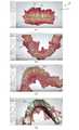
도 1은 3SHAPE 회사의 치아 CAD/CAM 시스템의 일 예를 보여주는 도면이다.1 is a view showing an example of a dental CAD / CAM system of 3SHAPE company.
치아 CAD/CAM 시스템(10)에서 CBCT(Cone Beam CT)로 측정한 치아 스캔 데이터를 로딩부(미표시)를 통해 로딩(loading)한 후 표시부(11)를 통해 3차원으로 환자의 치아(12) 및 잇몸(13)을 동시에 보여준다. 표시부(11)에는 치아(12)와 잇몸(13)이 구별되어 보이지만 데이터 상으로는 구별되어 있지 않아 도 1(d)와 같이 치아(12)만을 잇몸으로부터 구별하여 치아 CAD/CAM 시스템(10)에서 처리할 수 없다. 이에 3SHAPE 회사는 도 1(b)와 같이 치아 CAD/CAM 시스템(10)에서 마우스와 같은 입력부를 통해 각각의 치아(12)에 두 개의 서로 다른 점(14, 15)을 클릭하여 표시하면 치아 CAD/CAM 시스템(10)의 계산부(미표시)에서 자동으로 계산하여 치아(12)를 잇몸(13)과 구별하여 도 1(c)와 같이 표시부(11)에 치아(12)와 잇몸(13)을 구별하는 치아 분할선(16)을 표시하도록 하였다. 이후 치아 스캔 데이터로부터 치아 모형 데이터를 생성하여 도 1(d)와 같이 표시부(11)에서 치아(12) 각각을 치아 CAD/CAM 시스템(10)에서 처리할 수 있도록 하였다.After loading the tooth scan data measured by CBCT (Cone Beam CT) in the dental CAD/
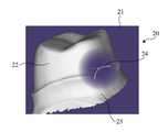
도 2는 Exocad 회사의 치아 CAD/CAM 시스템의 일 예를 보여주는 도면이다.2 is a view showing an example of a dental CAD/CAM system of Exocad company.
Exocad 회사의 치아 CAD/CAM 시스템(20)에서는 치아 스캔 데이터를 로딩부(미표시)를 통해 로딩(loading)한 후 표시부(21)를 통해 3차원으로 환자의 치아(22) 및 잇몸(23)을 동시에 보여주며 치아(22)와 잇몸(23) 사이의 임의 점(24) 하나를 찍어서 자동으로 치아(22)와 잇몸(23)을 구분하여 치아 CAD/CAM 시스템(20)에서 사용할 수 있는 치아 모형 데이터를 얻도록 하고 있다.In the dental CAD/
도 1 및 도 2에 기재된 것과 같이 사용자가 점 하나 또는 두 개를 선택하여 자동으로 치아 모형 데이터를 얻는 경우, 치아의 모양과 크기가 사람 및 치아 종류에 따라 차이가 크기 때문에 정확한 치아 모형 데이터를 얻을 수 없는 문제가 있다. 반면에 사용자에게 여러 점을 선택하게 하는 것은 사용자의 편의성을 떨어뜨리는 문제가 있다.1 and 2, when a user selects one or two points to automatically obtain tooth model data, accurate shape data is obtained because the shape and size of the teeth differ greatly depending on the person and the type of teeth. There are problems that cannot be. On the other hand, having the user select multiple points has a problem of reducing user convenience.
본 개시는 사용자의 사용 편의를 향상시키면서도 치아 스캔 데이터로부터 자동으로 정확한 치아 모형 데이터를 얻을 수 있는 치아 CAD/CAM 시스템과 같은 치아 분할 시스템 및 방법을 제공하고자 한다.The present disclosure is intended to provide a dental segmentation system and method such as a dental CAD/CAM system that can automatically obtain accurate dental model data from dental scan data while improving user convenience.
이에 대하여 '발명을 실시하기 위한 구체적인 내용'의 후단에 기술한다.This will be described at the end of'Details for Carrying Out the Invention'.
여기서는, 본 개시의 전체적인 요약(Summary)이 제공되며, 이것이 본 개시의 외연을 제한하는 것으로 이해되어서는 아니된다(This section provides a general summary of the disclosure and is not a comprehensive disclosure of its full scope or all of its features).Here, an overall summary of the present disclosure is provided, and this should not be understood as limiting the appearance of the present disclosure (This section provides a general summary of the disclosure and is not a comprehensive disclosure of its full scope or all of its features).
본 개시에 따른 일 태양에 의하면(According to one aspect of the present disclosure), 치아 분할 시스템에 있어서, 치아 스캔 데이터를 로딩(Loading)하는 로딩부; 로딩부에 의해 로딩된 치아 스캔 데이터를 표시하는 표시부;로서, 치아와 잇몸을 동시에 표시하는 표시부; 표시부에 표시된 각각의 치아에 치아 분할 마크(Mark)를 입력하는 입력부; 그리고 치아 분할 마크를 기준으로 치아를 잇몸으로부터 분할하는 계산부;를 포함하는 치아 분할 시스템이 제공된다.According to an aspect of the present disclosure (According to one aspect of the present disclosure), a tooth segmentation system comprising: a loading unit for loading dental scan data; A display unit for displaying the tooth scan data loaded by the loading unit; A display unit for displaying the teeth and gums at the same time; An input unit for inputting a tooth segmentation mark to each tooth displayed on the display unit; And it is provided with a tooth segmentation system comprising; a calculation unit for dividing the teeth from the gums based on the tooth segmentation mark.
본 개시에 따른 다른 태양에 의하면(According to another aspect of the present disclosure), 치아 분할 방법에 있어서, 로딩부가 치아 스캔 데이터를 로딩하는 단계; 표시부가 치아 스캔 데이터에 따라 치아와 잇몸을 표시하는 단계; 입력부가 표시부에 표시된 각각의 치아에 치아 분할 마크를 입력하는 단계; 그리고 계산부가 치아 분할 마크를 기준으로 치아를 잇몸으로부터 분할하는 단계;를 포함하는 치아 분할 방법이 제공된다.According to another aspect of the present disclosure (According to another aspect of the present disclosure), a tooth segmentation method comprising: loading a tooth scan data by a loading unit; A display unit displaying teeth and gums according to the tooth scan data; Inputting a tooth division mark into each tooth displayed on the display unit; And a step of dividing the teeth from the gums based on the tooth dividing mark by the calculation unit.
이에 대하여 '발명의 실시를 위한 구체적인 내용'의 후단에 기술한다.This will be described at the end of'Details for the Invention'.
도 1은 3SHAPE 회사의 치아 CAD/CAM 시스템 일 예를 보여주는 도면,
도 2는 Exocad 회사의 치아 CAD/CAM 시스템 일 예를 보여주는 도면,
도 3은 본 개시에 따른 치아 분할 시스템의 일 예를 나타내는 도면,
도 4는 본 개시에 따른 치아 분할 시스템의 사용방법의 일 예를 보여주는 도면,
도 5는 본 개시에 따른 치아 분할 시스템의 사용방법의 다른 예를 보여주는 도면,
도 6은 본 개시에 따른 치아 분할 시스템 사용방법의 또 다른 예를 보여주는 도면,
도 7은 본 개시에 따른 치아 분할 시스템 사용방법의 또 다른 일 예를 보여주는 도면.1 is a view showing an example of a dental CAD / CAM system 3SHAPE company,
2 is a view showing an example of a dental CAD/CAM system of the Exocad company,
3 is a view showing an example of a tooth segmentation system according to the present disclosure;
4 is a view showing an example of a method of using a tooth splitting system according to the present disclosure,
5 is a view showing another example of the method of using the tooth segmentation system according to the present disclosure,
6 is a view showing another example of a method of using a tooth segmentation system according to the present disclosure,
7 is a view showing another example of a method of using a tooth splitting system according to the present disclosure.
이하, 본 개시를 첨부된 도면을 참고로 하여 자세하게 설명한다(The present disclosure will now be described in detail with reference to the accompanying drawing(s)). 또한 본 명세서에서 상측/하측, 위/아래 등과 같은 방향 표시는 도면을 기준으로 한다.Hereinafter, the present disclosure will be described in detail with reference to the accompanying drawings (The present disclosure will now be described in detail with reference to the accompanying drawing(s)). In addition, in the present specification, indications of directions such as top/bottom, top/bottom, etc. are based on drawings.
도 3은 본 개시에 따른 치아 분할 시스템의 일 예를 나타내는 도면이다.3 is a view showing an example of a tooth segmentation system according to the present disclosure.
치아 분할 시스템(100)은 CBCT 등으로부터 얻은 치아 스캔 데이터를 불러들이는 로딩부(110), 로딩부(110)에 의해 불러들인(loading) 치아 스캔 데이터를 표시하는 표시부(120), 표시부(120)에 표시된 각각의 치아에 치아 분할 마크를 입력하는 입력부(130), 치아 분할 마크를 기준으로 치아를 잇몸으로부터 분할하는 계산부(140) 및 치아 스캔 데이터로부터 치아 모형 데이터를 생성하는 데이터 생성부(150)를 포함할 수 있다. 치아 분할 시스템(100)은 예를 들어 퍼스널 컴퓨터나 노트북과 같은 컴퓨터 시스템일 수 있다. 치아 스캔 데이터 및 치아 모형 데이터를 저장하는 저장부(160)를 추가로 포함할 수 있다. 치아 분할 시스템(100)의 사용방법은 도 4에서 설명한다.The
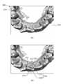
도 4는 본 개시에 따른 치아 분할 시스템의 사용방법의 일 예를 보여주는 도면이다.4 is a view showing an example of a method of using a tooth splitting system according to the present disclosure.
저장부(160)에 저장된 치아 스캔 데이터를 로딩부(110)가 판독하여 표시부(120)에 도 4(a)와 같이 표시한다. 도 4(a)에는 하악 치아 구조(200)만을 도시하였으며 상악 치아 구조에 대해서도 동일한 방법이 적용될 수 있다. 표시부(120)는 예를 들어 LCD 모니터일 수 있다. 표시부(120)에는 치아(210)와 잇몸(220)이 동시에 표시되었다. 도 4(b)에 도시된 것처럼 입력부(130)가 치아 분할 마크(230, Mark)를 각각의 치아(210)에 형성한다. 입력부(130)는 키보드나 마우스 등이 될 수 있다. 치아 분할 마크(230)는 큰 원(231)과 큰 원(231) 안에 들어간 작은 원(232)으로 구성될 수 있다. 작은 원(232)은 치아(210)의 윗면(211)에 형성된다. 더 나아가 작은 원(232)은 치아(210) 윗면(211)의 경계(212) 안에 형성되는 것이 바람직하다. 작은 원(232)이 치아(210) 윗면(211)의 경계(212)를 벗어나서 형성되는 경우에는 계산부(140)가 치아(210)를 잇몸(220)으로부터 정확히 분리하지 못할 수 있기 때문이다. 작은 원(232)이 치아(210) 윗면(211)에 형성되는 방법에 대해서는 도 5에서 다시 설명한다. 큰 원(231)은 치아 윗면(211)의 경계(212) 밖에 형성된다. 바람직하게는 큰 원(231)은 이웃한 치아의 윗면의 경계를 넘지 않는 것이 좋다. 치아 분할 마크(230)가 각각의 치아(210)에 형성되는 경우 자동으로 작은 원(232)과 큰 원(231) 안에는 다수의 점(2311, 2321)이 형성된다. 다수의 점(2311, 2321)은 치아 스캔 데이터를 구성하는 메쉬의 꼭지점에 해당한다. 즉 3차원 치아 스캔 데이터는 무수히 많은 메쉬로 구성되며 메쉬의 꼭지점 정보를 갖고 있다. 따라서 치아 분할 마크(230)가 각각의 치아에 형성되는 경우 작은 원(232)과 큰 원(231) 내에 다수의 점(2311, 2321)이 자동으로 선정되게 할 수 있다. 계산부(140)는 작은 원(232) 안에 자동으로 선정된 다수의 점(2321)과 큰 원(231)과 작은 원(232) 사이에 자동으로 선정된 다수의 점(2322)을 기준으로 계산하여 치아(210)와 잇몸(220)을 구분할 수 있다. 계산부(140)가 다수의 점(2311, 2322)으로부터 치아(210)와 잇몸(220)을 분할하는 알고리즘은 먼저 작은 원(232) 안에 포함되는 점(2322)에 1의 값을 주고, 큰 원(231)에 포함되는 점(2311) 중 큰 원(231)의 경계에 위치하는 점에 0의 값을 준다. 이후 메쉬 곡면상의 라플라스 방정식을 세운다. 이 때 각 점(2311, 2321)을 잇는 각 변에는 계수 값을 지정하는데, 오목한 곡면 부근의 변들에 작은 값을 주어 치아와 잇몸의 경계를 보다 명확히 구별할 수 있다. 라플라스 방정식의 해를 구하면, 큰 원(231)의 경계에 있는 것을 제외한 큰 원(231) 안에 포함된 점(2311)은 0과 1 사이의 실수값을 가지게 된다. 이 값들은 1의 값을 갖는 작은 원(232)의 점(2321)과 0의 값을 갖는 큰 원(231)의 경계에 있는 점(2311)들 사이를 보간하는 값이 된다. 마지막으로, 0과 1 사이의 적당한 실수 값을 선택하여 메쉬 곡면상의 등치선을 계산하면, 치아와 잇몸의 경계가 된다. 이 때, 등치선 계산에 사용하는 실수 값은 메쉬 정보를 이용해 자동으로 선택할 수 있다. 계산부(140)는 중앙처리장치(CPU) 일 수 있다. 계산부(140)에 의해 치아(210)가 잇몸(220)으로부터 분할된 후 데이터 생성부(150)는 분할된 치아(210)에 대한 정보를 이용하여 치아 스캔 데이터로부터 치아 모형 데이터를 생성할 수 있다. 생성된 치아 모형 데이터는 저장부(160)에 저장되어 필요할 때 불러 사용할 수 있다. 또한 치아 분할 마크(230)의 형상으로 원을 도시하였지만 본 개시의 범위 내에서 사각형, 삼각형 또는 다각형 등 모든 도형이 가능하다. 즉 치아 분할 마크(230)는 큰 도형 안에 작은 도형이 들어간 형태이다.The
도 5는 본 개시에 따른 치아 분할 시스템의 사용방법의 다른 예를 보여주는 도면이다.5 is a view showing another example of a method of using a tooth splitting system according to the present disclosure.
치아 분할 마크(230)의 작은 원(232)을 오목한 부분이 있는 치아 윗면(211)에 형성하는 경우, 작은 원(232) 안에 도 5(b)와 같이 오목한 부분이 들어가도록 형성하는 것이 바람직하다. 도 5(a)와 같이 작은 원(232)이 오목한 부분 안쪽에 형성되는 경우에는 계산부(140)가 치아를 잇몸으로부터 정확히 분리하지 못할 수 있기 때문이다.When the
도 6은 본 개시에 따른 치아 분할 시스템의 사용방법의 또 다른 예를 보여주는 도면이다.6 is a view showing another example of a method of using a tooth segmentation system according to the present disclosure.
치아 분할 마크(230)의 작은 원(232)은 치아 윗면 뿐 아니라 도 6(a) 및 도 6(b)와 같이 치아면(213) 어디에도 형성될 수 있다. 다만 작은 원(232)은 형성된 치아면(213)이 포함된 치아(210)의 경계(212)를 벗어나서 형성되지 않는 것이 바람직하다. 또한 오목한 부분이 많이 포함된 치아 윗면에 작은 원(232)이 형성되는 것이 바람직하다. 또한 큰 원(231)은 작은 원(232)이 형성된 치아면(213)이 포함된 치아(210)의 경계(212)를 벗어나서 형성되는 것이 바람직하다.The
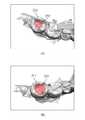
도 7은 본 개시에 따른 치아 분할 시스템의 사용방법의 또 다른 일 예를 보여주는 도면이다.7 is a view showing another example of a method of using a tooth splitting system according to the present disclosure.
계산부에 의해 치아(210)와 잇몸(220)이 분할된 것을 도 7(a)와 같이 표시부에 치아 분할선(240)으로 표시될 수 있다. 도 7(a)의 치아 분할선(240)을 보면 치아 분할선(240)이 옆 치아를 침범한 부분(241)이 있다. 정확한 치아 분할을 위해 사용자는 입력부를 통해 도 7(b)와 같이 치아 분할선(240) 중 옆 치아를 침범한 부분(241)을 움직여 잘못된 부분을 수정할 수 있다.The
이하 본 개시의 다양한 실시 형태에 대하여 설명한다.Hereinafter, various embodiments of the present disclosure will be described.
(1) 치아 분할 시스템에 있어서, 치아 스캔 데이터를 로딩(Loading)하는 로딩부; 로딩부에 의해 로딩된 치아 스캔 데이터를 표시하는 표시부;로서, 치아와 잇몸을 표시하는 표시부; 표시부에 표시된 각각의 치아에 치아 분할 마크(Mark)를 입력하는 입력부; 그리고 치아 분할 마크를 기준으로 치아를 잇몸으로부터 분할하는 계산부;를 포함하는 치아 분할 시스템.(1) A tooth segmentation system comprising: a loading unit for loading tooth scan data; A display unit for displaying the tooth scan data loaded by the loading unit; A display unit for displaying the teeth and gums; An input unit for inputting a tooth segmentation mark to each tooth displayed on the display unit; And a calculation unit for dividing the teeth from the gums based on the tooth dividing marks.
(2) 계산부에 의해 잇몸으로부터 분할된 치아에 대한 치아 모형 데이터를 치아 스캔 데이터로부터 생성하는 데이터 생성부;를 추가로 포함하는 치아 분할 시스템.(2) a tooth segmentation system further comprising; a data generator for generating tooth model data for teeth divided from the gums by the calculation unit from the tooth scan data.
(3) 치아 분할 마크는 큰 도형과 큰 도형 안에 들어간 작은 도형으로 구성된 치아 분할 시스템.(3) The tooth segmentation mark is a tooth segmentation system consisting of a large figure and a small figure that fits inside the big figure.
(4) 작은 도형이 각각의 치아면에 형성되는 치아 분할 시스템.(4) A tooth segmentation system in which small figures are formed on each tooth surface.
(5) 치아면에 오목한 부분이 있는 경우 작은 도형 안에 오목한 부분이 들어가도록 형성되는 치아 분할 시스템.(5) When the tooth surface has a concave portion, the tooth segmentation system is formed so that the concave portion enters the small figure.
(6) 작은 도형이 치아면의 경계 안에 형성되는 치아 분할 시스템.(6) A tooth segmentation system in which small figures are formed within the boundaries of the tooth surface.
(7) 큰 도형은 각각의 치아면의 경계 밖에 형성되는 치아 분할 시스템.(7) A tooth segmentation system in which a large figure is formed outside the boundary of each tooth surface.
(8) 작은 도형은 각각의 치아 윗면의 경계 안에 형성되고, 큰 도형은 각각의 치아 윗면의 경계 밖에 형성되는 치아 분할 시스템.(8) A tooth segmentation system in which a small figure is formed within the boundary of the top surface of each tooth, and a large figure is formed outside the boundary of the top surface of each tooth.
(9) 계산부는 작은 도형 안에 형성된 점과 작은 도형과 큰 도형 사이에 형성된 점을 기준으로 치아를 분할하는 치아 분할 시스템.(9) The tooth division system which divides a tooth based on a point formed in a small figure and a point formed between a small figure and a big figure.
(10) 치아 분할 방법에 있어서, 로딩부가 치아 스캔 데이터를 로딩하는 단계; 표시부가 치아 스캔 데이터에 따라 치아와 잇몸을 표시하는 단계; 입력부가 표시부에 표시된 각각의 치아에 치아 분할 마크를 입력하는 단계; 그리고 계산부가 치아 분할 마크를 기준으로 치아를 잇몸으로부터 분할하는 단계;를 포함하는 치아 분할 방법.(10) A tooth segmentation method comprising: loading a tooth scan data by a loading unit; A display unit displaying teeth and gums according to the tooth scan data; Inputting a tooth division mark into each tooth displayed on the display unit; And Computing unit dividing the teeth from the gums based on the tooth division mark; tooth segmentation method comprising a.
(11) 치아 분할 마크는 큰 도형과 큰 도형 안에 작은 도형으로 구성된 치아 분할 방법.(11) A tooth segmentation mark consists of a large figure and a small figure in a large figure.
(12) 작은 도형은 치아면의 경계 안에 형성되고, 큰 도형은 치아면의 경계 밖에 형성되는 치아 분할 방법.(12) A method of segmenting a tooth in which a small figure is formed within the boundary of the tooth surface, and a large figure is formed outside the boundary of the tooth surface.
본 개시에 따르면, 사용자가 쉽게 사용하면서도 치아와 잇몸을 정확히 분할할 수 있는 치아 분할 시스템 및 방법을 얻을 수 있다.According to the present disclosure, it is possible to obtain a tooth splitting system and method that can be accurately divided between a tooth and a gum while being easily used by a user.
치아 분할 시스템 : 10, 20, 100
치아 분할 마크 : 230Tooth segmentation system: 10, 20, 100
Tooth segmentation mark: 230
Claims (12)
Translated fromKorean치아 스캔 데이터를 로딩(Loading)하는 로딩부;
로딩부에 의해 로딩된 치아 스캔 데이터를 표시하는 표시부;로서, 치아와 잇몸을 표시하는 표시부;
표시부에 표시된 각각의 치아에 치아 분할 마크(Mark)를 입력하는 입력부; 그리고
치아 분할 마크를 기준으로 치아를 잇몸으로부터 분할하는 계산부;를 포함하며,
치아 분할 마크는 큰 도형과 큰 도형 안에 들어간 작은 도형으로 구성되며,
큰 도형과 작은 도형은 각각 단일폐곡선이며,
큰 도형과 작은 도형 안에 자동으로 다수의 점이 형성되며,
계산부는 작은 도형 안에 형성된 점과 작은 도형과 큰 도형 사이에 형성된 점을 기준으로 치아를 분할하는 치아 분할 시스템.In the tooth segmentation system,
A loading unit for loading tooth scan data;
A display unit for displaying the tooth scan data loaded by the loading unit; A display unit for displaying the teeth and gums;
An input unit for inputting a tooth segmentation mark to each tooth displayed on the display unit; And
Includes; calculation unit for dividing the teeth from the gums based on the tooth division mark,
The tooth segmentation mark consists of a large figure and a small figure that fits inside the big figure,
The large and small figures are each a single closed curve,
A large number of dots are automatically formed in large and small shapes.
The calculation unit divides a tooth based on a point formed in a small figure and a point formed between a small figure and a big figure.
계산부에 의해 잇몸으로부터 분할된 치아에 대한 치아 모형 데이터를 치아 스캔 데이터로부터 생성하는 데이터 생성부;를 추가로 포함하는 치아 분할 시스템.The method according to claim 1,
A tooth segmentation system further comprising; a data generation unit that generates tooth model data for teeth divided from the gums by the calculation unit from the tooth scan data.
작은 도형이 각각의 치아면에 형성되는 치아 분할 시스템.The method according to claim 1,
A tooth segmentation system in which small shapes are formed on each tooth surface.
치아면에 오목한 부분이 있는 경우 작은 도형 안에 오목한 부분이 들어가도록 형성되는 치아 분할 시스템.The method according to claim 4,
A tooth segmentation system that is formed so that a concave portion enters a small figure when the tooth surface has a concave portion.
작은 도형이 치아면의 경계 안에 형성되는 치아 분할 시스템.The method according to claim 4,
A tooth segmentation system in which small shapes are formed within the boundaries of the tooth surface.
큰 도형은 각각의 치아면의 경계 밖에 형성되는 치아 분할 시스템.The method according to claim 1,
A tooth segmentation system in which large shapes are formed outside the boundaries of each tooth surface.
작은 도형은 각각의 치아 윗면의 경계 안에 형성되고,
큰 도형은 각각의 치아 윗면의 경계 밖에 형성되는 치아 분할 시스템.The method according to claim 1,
Small shapes are formed within the boundaries of the top of each tooth,
A large tooth shape is a tooth segmentation system that is formed outside the boundaries of the top of each tooth.
Priority Applications (3)
| Application Number | Priority Date | Filing Date | Title |
|---|---|---|---|
| KR1020180098286AKR102132369B1 (en) | 2018-08-23 | 2018-08-23 | Tooth segmentation system and method |
| US17/270,091US11883249B2 (en) | 2018-08-23 | 2019-08-23 | Tooth separation systems and methods |
| PCT/KR2019/010751WO2020040588A1 (en) | 2018-08-23 | 2019-08-23 | System and method for separating teeth |
Applications Claiming Priority (1)
| Application Number | Priority Date | Filing Date | Title |
|---|---|---|---|
| KR1020180098286AKR102132369B1 (en) | 2018-08-23 | 2018-08-23 | Tooth segmentation system and method |
Publications (2)
| Publication Number | Publication Date |
|---|---|
| KR20200022564A KR20200022564A (en) | 2020-03-04 |
| KR102132369B1true KR102132369B1 (en) | 2020-07-09 |
Family
ID=69593276
Family Applications (1)
| Application Number | Title | Priority Date | Filing Date |
|---|---|---|---|
| KR1020180098286AActiveKR102132369B1 (en) | 2018-08-23 | 2018-08-23 | Tooth segmentation system and method |
Country Status (3)
| Country | Link |
|---|---|
| US (1) | US11883249B2 (en) |
| KR (1) | KR102132369B1 (en) |
| WO (1) | WO2020040588A1 (en) |
Cited By (4)
| Publication number | Priority date | Publication date | Assignee | Title |
|---|---|---|---|---|
| WO2022265149A1 (en)* | 2021-06-15 | 2022-12-22 | 이마고웍스 주식회사 | Method for automatically separating teeth from three-dimensional scan data by using deep learning, and computer-readable recording medium having recorded thereon program for executing same on computer |
| WO2023018206A1 (en)* | 2021-08-10 | 2023-02-16 | 이노디테크 주식회사 | Method and apparatus for recommending orthodontic treatment plan by separating tooth object from three-dimensional oral scan data and automatically determining positional abnormality of tooth, and computer-readable recording medium |
| KR20230030109A (en)* | 2021-08-24 | 2023-03-06 | 이노디테크 주식회사 | Automatic determination system for position abnormality of teeth through 3d scan data of teeth |
| EP4307240A4 (en)* | 2021-03-11 | 2025-03-26 | Medit Corp. | METHOD FOR IDENTIFYING A SELECTION AREA IN AN ORAL IMAGE AND ASSOCIATED DEVICE |
Families Citing this family (4)
| Publication number | Priority date | Publication date | Assignee | Title |
|---|---|---|---|---|
| KR102453932B1 (en)* | 2020-12-28 | 2022-10-14 | 주식회사 크리에이티브마인드 | Method for recognizing teeth from 3D teeth data and apparatus therefor |
| US12387338B2 (en) | 2021-06-15 | 2025-08-12 | Imagoworks Inc. | Method for automated tooth segmentation of three dimensional scan data using deep learning and computer readable medium having program for performing the method |
| KR102641953B1 (en)* | 2021-06-22 | 2024-02-28 | 주식회사 쓰리디산업영상 | Tooth segmentation apparatus and method for tooth image |
| KR102750720B1 (en)* | 2022-06-07 | 2025-01-09 | 오스템임플란트 주식회사 | Crown Template Model Selection Method, Computing Device for Performing the Method and a Computer-readable Recording Medium therefor |
Citations (1)
| Publication number | Priority date | Publication date | Assignee | Title |
|---|---|---|---|---|
| JP2009146178A (en)* | 2007-12-14 | 2009-07-02 | Hitachi Medical Computer Systems Inc | Medical image diagnosis support apparatus and medical image diagnosis support program |
Family Cites Families (8)
| Publication number | Priority date | Publication date | Assignee | Title |
|---|---|---|---|---|
| US7004754B2 (en)* | 2003-07-23 | 2006-02-28 | Orametrix, Inc. | Automatic crown and gingiva detection from three-dimensional virtual model of teeth |
| US20080030497A1 (en)* | 2005-12-08 | 2008-02-07 | Yangqiu Hu | Three dimensional modeling of objects |
| KR20130044932A (en) | 2011-10-25 | 2013-05-03 | (주)쓰리디아이티 | An image matching method for orthodontics and production method for orthodontics device using the same |
| US8923581B2 (en)* | 2012-03-16 | 2014-12-30 | Carestream Health, Inc. | Interactive 3-D examination of root fractures |
| BR112018011227B1 (en) | 2015-12-04 | 2021-07-20 | 3Shape A/S | METHOD FOR COMPLETING A DIGITAL DENTAL CHART WITH DENTAL CONDITION INFORMATION FOR A PATIENT'S TEETH |
| EP4278957A3 (en)* | 2017-07-27 | 2024-01-24 | Align Technology, Inc. | System and methods for processing an orthodontic aligner by means of an optical coherence tomography |
| US11534974B2 (en)* | 2017-11-17 | 2022-12-27 | Align Technology, Inc. | Customized fabrication of orthodontic retainers based on patient anatomy |
| EP3517071B1 (en)* | 2018-01-30 | 2022-04-20 | Dental Monitoring | System for enriching a digital dental model |
- 2018
- 2018-08-23KRKR1020180098286Apatent/KR102132369B1/enactiveActive
- 2019
- 2019-08-23USUS17/270,091patent/US11883249B2/enactiveActive
- 2019-08-23WOPCT/KR2019/010751patent/WO2020040588A1/ennot_activeCeased
Patent Citations (1)
| Publication number | Priority date | Publication date | Assignee | Title |
|---|---|---|---|---|
| JP2009146178A (en)* | 2007-12-14 | 2009-07-02 | Hitachi Medical Computer Systems Inc | Medical image diagnosis support apparatus and medical image diagnosis support program |
Cited By (5)
| Publication number | Priority date | Publication date | Assignee | Title |
|---|---|---|---|---|
| EP4307240A4 (en)* | 2021-03-11 | 2025-03-26 | Medit Corp. | METHOD FOR IDENTIFYING A SELECTION AREA IN AN ORAL IMAGE AND ASSOCIATED DEVICE |
| WO2022265149A1 (en)* | 2021-06-15 | 2022-12-22 | 이마고웍스 주식회사 | Method for automatically separating teeth from three-dimensional scan data by using deep learning, and computer-readable recording medium having recorded thereon program for executing same on computer |
| WO2023018206A1 (en)* | 2021-08-10 | 2023-02-16 | 이노디테크 주식회사 | Method and apparatus for recommending orthodontic treatment plan by separating tooth object from three-dimensional oral scan data and automatically determining positional abnormality of tooth, and computer-readable recording medium |
| KR20230030109A (en)* | 2021-08-24 | 2023-03-06 | 이노디테크 주식회사 | Automatic determination system for position abnormality of teeth through 3d scan data of teeth |
| KR102620157B1 (en) | 2021-08-24 | 2024-01-03 | 이노디테크 주식회사 | Automatic determination system for position abnormality of teeth through 3d scan data of teeth |
Also Published As
| Publication number | Publication date |
|---|---|
| KR20200022564A (en) | 2020-03-04 |
| US20210205057A1 (en) | 2021-07-08 |
| US11883249B2 (en) | 2024-01-30 |
| WO2020040588A1 (en) | 2020-02-27 |
Similar Documents
| Publication | Publication Date | Title |
|---|---|---|
| KR102132369B1 (en) | Tooth segmentation system and method | |
| US11344392B2 (en) | Computer implemented method for modifying a digital three-dimensional model of a dentition | |
| US12138132B2 (en) | Method for generating dental models based on an objective function | |
| JP2022000211A (en) | Method and device for removing teeth row mesh braces | |
| US10561476B2 (en) | Generating a dynamic three-dimensional occlusogram | |
| CN101393653B (en) | Method for reconstructing three dimensional model of complete teeth through CT data of dentognathic gypsum model and dentognathic panoramic perspective view | |
| CN104093375B (en) | Determine the stress on tooth | |
| US8587582B2 (en) | Generating a dynamic three-dimensional occlusogram | |
| Mehl et al. | Biogeneric tooth: a new mathematical representation for tooth morphology in lower first molars | |
| EP3527163B1 (en) | Computer implemented method for modifying a digital three-dimensional model of a dentition | |
| JP2023014295A (en) | Method for cephalometric analysis | |
| US10346504B2 (en) | 3D modelling of bodies | |
| JP2020516335A (en) | Dynamic dental arch map | |
| Liao et al. | Automatic tooth segmentation of dental mesh based on harmonic fields | |
| US20220110726A1 (en) | Method For Producing A Dental Restoration | |
| JP2017213096A (en) | Tooth axis estimation program, tooth axis estimation apparatus and method thereof, tooth profile data generation program, tooth profile data generation apparatus and method thereof | |
| US11423804B2 (en) | Model generation for dental simulation | |
| BRPI0808607B1 (en) | METHOD OF GENERATING A REAL JAW MODEL AND APPLIANCE TO GENERATE A REAL JAW MODEL | |
| CN119923238A (en) | Dental Restoration Automation | |
| US10582992B2 (en) | Method for determining a mapping of the contacts and/or distances between the maxillary and mandibular arches of a patient | |
| Wongwaen et al. | Computerized algorithm for 3D teeth segmentation | |
| US20230397972A1 (en) | Method and device for processing three-dimensional oral cavity model and computer-readable recording medium | |
| KR20200016106A (en) | Apparatus, method and program for setting a transparent orthodontic model using dynamic function | |
| Kim et al. | Evaluation of validity of three dimensional dental digital model made from blue LED dental scanner | |
| KR102602121B1 (en) | Method for obtaining images of teeth based on arch line, device and recording medium thereof |
Legal Events
| Date | Code | Title | Description |
|---|---|---|---|
| A201 | Request for examination | ||
| PA0109 | Patent application | Patent event code:PA01091R01D Comment text:Patent Application Patent event date:20180823 | |
| PA0201 | Request for examination | ||
| E902 | Notification of reason for refusal | ||
| PE0902 | Notice of grounds for rejection | Comment text:Notification of reason for refusal Patent event date:20191217 Patent event code:PE09021S01D | |
| PG1501 | Laying open of application | ||
| E701 | Decision to grant or registration of patent right | ||
| PE0701 | Decision of registration | Patent event code:PE07011S01D Comment text:Decision to Grant Registration Patent event date:20200624 | |
| PR0701 | Registration of establishment | Comment text:Registration of Establishment Patent event date:20200703 Patent event code:PR07011E01D | |
| PR1002 | Payment of registration fee | Payment date:20200706 End annual number:3 Start annual number:1 | |
| PG1601 | Publication of registration | ||
| PR1001 | Payment of annual fee | Payment date:20230509 Start annual number:4 End annual number:4 | |
| PR1001 | Payment of annual fee | Payment date:20250521 Start annual number:6 End annual number:6 |