KR102128604B1 - Base station apparatus for mobile communication system - Google Patents
Base station apparatus for mobile communication systemDownload PDFInfo
- Publication number
- KR102128604B1 KR102128604B1KR1020130073692AKR20130073692AKR102128604B1KR 102128604 B1KR102128604 B1KR 102128604B1KR 1020130073692 AKR1020130073692 AKR 1020130073692AKR 20130073692 AKR20130073692 AKR 20130073692AKR 102128604 B1KR102128604 B1KR 102128604B1
- Authority
- KR
- South Korea
- Prior art keywords
- path
- signal
- duplexer
- terminal
- antenna
- Prior art date
- Legal status (The legal status is an assumption and is not a legal conclusion. Google has not performed a legal analysis and makes no representation as to the accuracy of the status listed.)
- Active
Links
- 238000010295mobile communicationMethods0.000titleclaimsabstractdescription20
- 230000005540biological transmissionEffects0.000claimsabstractdescription96
- 238000012545processingMethods0.000claimsabstractdescription28
- 238000000034methodMethods0.000claimsdescription14
- 230000010287polarizationEffects0.000claimsdescription7
- 238000002955isolationMethods0.000description35
- 238000010586diagramMethods0.000description10
- 238000004519manufacturing processMethods0.000description4
- 238000000926separation methodMethods0.000description4
- 238000004891communicationMethods0.000description3
- 101150092978Slc25a4 geneProteins0.000description2
- 238000011161developmentMethods0.000description2
- 230000009977dual effectEffects0.000description2
- 238000012986modificationMethods0.000description2
- 230000004048modificationEffects0.000description2
- 230000001413cellular effectEffects0.000description1
- 239000000470constituentSubstances0.000description1
- 238000001914filtrationMethods0.000description1
- 238000012546transferMethods0.000description1
Images


Classifications
- H—ELECTRICITY
- H04—ELECTRIC COMMUNICATION TECHNIQUE
- H04B—TRANSMISSION
- H04B7/00—Radio transmission systems, i.e. using radiation field
- H04B7/02—Diversity systems; Multi-antenna system, i.e. transmission or reception using multiple antennas
- H04B7/04—Diversity systems; Multi-antenna system, i.e. transmission or reception using multiple antennas using two or more spaced independent antennas
- H04B7/0413—MIMO systems
- H—ELECTRICITY
- H04—ELECTRIC COMMUNICATION TECHNIQUE
- H04B—TRANSMISSION
- H04B7/00—Radio transmission systems, i.e. using radiation field
- H04B7/02—Diversity systems; Multi-antenna system, i.e. transmission or reception using multiple antennas
- H04B7/022—Site diversity; Macro-diversity
- H04B7/024—Co-operative use of antennas of several sites, e.g. in co-ordinated multipoint or co-operative multiple-input multiple-output [MIMO] systems
Landscapes
- Engineering & Computer Science (AREA)
- Computer Networks & Wireless Communication (AREA)
- Signal Processing (AREA)
- Transceivers (AREA)
- Mobile Radio Communication Systems (AREA)
- Radio Transmission System (AREA)
Abstract
Translated fromKoreanDescription
Translated fromKorean본 발명은 무선 통신(PCS, Cellular, CDMA, GSM, LTE, 등) 시스템의 중계기를 비롯한 기지국에 관한 것으로서, 특히, MIMO(Multi Input Multi Output) 방식으로 처리되는 송신 신호 및 수신 신호간에 더욱 향상된 격리도를 제공할 수 있도록 하기 위한 이동통신 시스템의 기지국 장치에 관한 것이다.The present invention relates to a base station including a repeater of a wireless communication (PCS, Cellular, CDMA, GSM, LTE, etc.) system, and more particularly, improved isolation between a transmission signal and a reception signal processed by a MIMO (Multi Input Multi Output) method It relates to a base station apparatus of a mobile communication system to provide a.
무선 통신 시스템의 중계기를 비롯한 기지국에 사용되는 안테나는 다양한 형태와 구조가 있을 수 있으며, 최근 무선 통신 안테나는 편파 다이버시티 방식을 적용하여 2T2R(2Tx/2Rx) MIMO 방식의 이중편파 안테나 구조를 일반적으로 사용하고 있다. 이 경우에 각 송수신경로의 신호들은 각각 듀플렉서를 이용하여 송신 및 수신 신호를 격리하는 구조를 일반적으로 채용하고 있다.Antennas used in base stations including repeaters of wireless communication systems may have various shapes and structures, and recently, wireless communication antennas have been applied to a polarization diversity scheme, so that a 2T2R (2Tx/2Rx) MIMO scheme dual polarization antenna structure is generally used. I am using it. In this case, the signals of each transmission/reception path generally employ a structure in which transmission and reception signals are separated using duplexers.
도 1은 종래의 일 실시예에 따른 이동통신 시스템의 기지국 장치의 블록 구성도로서, 도 1에는 일반적인 이동통신 기지국에서 사용하는 2T2R MIMO 구조의 안테나 시스템(10)과, 이의 각 송수신 경로에 제공되는 제1 및 제2 듀플렉서(20, 21)가 개시되고 있다. 안테나 시스템(10)에는 2T2R 구조에서 제1경로(P0)에 대한 신호를 송신 및 수신하는 제1 안테나(Ant0; 100)와, 제2경로(P1)에 대한 신호를 송신 및 수신하는 제2 안테나(Ant1; 101)가 구비되며, 제1 및 제2 안테나(100, 101)는 서로 직교하는 편파를 발생하게 설치된다.1 is a block diagram of a base station apparatus of a mobile communication system according to an embodiment of the prior art. In FIG. 1, a 2T2R MIMO
또한, 안테나 시스템(10)의 제1 및 제2 안테나(100, 101)와 각각 연결되어, 각각 제1 및 제2경로(P0, P1)의 송수신 신호를 분리 또는 결합하기 위한 제1 및 제2 듀플렉서(20, 21)가 구비되며, 제1 듀플렉서(20)는 제1 송수신부(P0송수신부)(30)와 연결되고, 제2 듀플렉서(21)는 제2 송수신부(P1송수신부)(31)와 연결된다. 제1 송수신부(30)는 제1경로의 송수신 신호를 처리하며, 제2 송수신부(31)는 제2경로(P1)의 송수신 신호를 처리한다.In addition, the first and second antennas are connected to the first and
제1 듀플렉서(20)는 제1경로(P0)에 대한 송신 신호 및 수신 신호를 각각 처리하는 송신필터(Tx0; 204) 및 수신필터(Rx0; 206)가 T-정션(T-junction)(202)을 이용하여 연결하는 구조를 가지며, 제2 듀플렉서(21)는 제2경로(P1)에 대한 송신 신호 및 수신 신호를 각각 처리하는 송신필터(Tx1; 214) 및 수신필터(Rx1; 216)가 T-정션(212)을 이용하여 연결하는 구조를 가진다.The
이때, 제1경로(P0)에서 송신 신호와 수신 신호의 격리도는 제1경로(P0)의 송신 필터(204)와 수신필터(206)를 T-정션(202)으로 연결한 제1 듀플렉서(20)의 구현 시 발생하는 격리도에 해당하게 된다. 즉, 제1 듀플렉서(20)의 송신단 및 수신단의 간의 격리도가 제1경로(P0)에서의 전체 송신 및 수신 격리도가 된다. 마찬가지로, 제2경로(P1)에서 송신 신호와 수신 신호의 격리도는 송신 필터(214)와 수신필터(216)를 T-정션(212)으로 연결한 제2 듀플렉서(21)의 구현시 발생하는 송신단 및 수신단의 격리도에 해당하게 된다.At this time, the isolation degree of the transmission signal and the reception signal in the first path P0 is the
따라서, 송신 신호 및 수신 신호간의 격리도를 증가하기 위해서는, 제1 및 제2 듀플렉서(20, 21)에서 필터링 특성(예를 들어, 스커트 특성)을 향상시키는 방안이 실질적으로 유일하게 고려되고 있으며, 이 경우에, 각 송신 및 수신 필터들의 단수를 증가 하거나, 격리하고자 하는 주파수에 노치(notch)의 개수를 증가시키는 방안이 일반적으로 채용되고 있다. 그러나, 이러한 방안은 필터의 사이즈와 제작 및 생산 난이도가 증가하는 문제를 갖고 있다.Therefore, in order to increase the isolation between the transmission signal and the reception signal, a method for improving filtering characteristics (eg, skirt characteristics) in the first and
또한, 이동통신 시장에서 요구되는 더 빠른 처리 속도 및 향상된 품질에 부응하기 위하여, 각 기지국은 소형(또는 초소형)셀로 진화하고 있으며, 안테나 시스템 및 기지국 장비가 일체형으로 개발되고 있는 추세이므로, 상기한 송신 필터 및 수신 필터로 구성되는 듀플렉서를 더욱 작고 경량화하려는 요구가 커지고 있다. 따라서, 상기와 같이 듀플렉서의 사이즈 및 무게 등을 고려하면서, 상기 송신 신호 및 수신 신호간의 격리도를 증가시키는 것은 매우 어려운 과제였다.In addition, in order to meet the faster processing speed and improved quality required in the mobile communication market, each base station is evolving into a small (or ultra-small) cell, and since the antenna system and the base station equipment are being developed in one piece, the above-described transmission There is an increasing demand to make the duplexer composed of a filter and a receiving filter smaller and lighter. Therefore, while considering the size and weight of the duplexer as described above, it was a very difficult task to increase the isolation between the transmission signal and the reception signal.
따라서, 본 발명의 목적은 송수신 경로의 송신 및 수신 신호를 처리하는 듀플렉서의 사이즈 및 무게를 줄이면서도, 또는 듀플렉서의 개발 및 생산 난이도를 낮추면서도, 송신 신호 및 수신 신호간의 격리도를 높이거나, 일정 요구 수준의 격리도를 유지 및 만족시킬 수 있도록 하기 위한 장치를 제공함에 있다.Accordingly, an object of the present invention is to reduce the size and weight of a duplexer that processes transmission and reception signals in a transmission/reception path, or to reduce the development and production difficulty of a duplexer, to increase the isolation between the transmission signal and the reception signal, or to require a certain amount. It is to provide a device for maintaining and satisfying the level of isolation.
상기한 목적을 달성하기 위하여 본 발명의 일 특징에 따르면, 이동통신 시스템의 기지국 장치에 있어서; MIMO(Multi Input Multi Output) 경로 중 제1경로에 대한 신호를 송수신하는 제1 안테나와, MIMO 경로중 제2경로에 대한 신호를 송수신하는 제2 안테나를 구비하는 안테나 시스템과; 상기 제1경로의 송신 신호를 처리하는 송신 필터와, 상기 제2경로의 수신 신호를 처리하는 수신 필터를 구비하는 제1 듀플렉서와; 상기 제1경로의 수신 신호를 처리하는 수신 필터와, 상기 제2경로의 송신 신호를 처리하는 송신 필터를 구비하는 제2 듀플렉서와; 상기 제1 듀플렉서에서 제공되는 송신 신호는 상기 제1 안테나로 제공하며, 상기 제1 안테나에서 제공되는 수신 신호는 상기 제2 듀플렉서로 제공하며, 상기 제2 듀플렉서에서 제공되는 송신 신호는 상기 제2 안테나로 제공하며, 상기 제2 안테나에서 제공되는 수신 신호는 상기 제1 듀플렉서로 제공하는 경로 변경부를 포함함을 특징으로 한다.According to an aspect of the present invention to achieve the above object, in a base station apparatus of a mobile communication system; An antenna system having a first antenna for transmitting and receiving a signal for a first path in a multi input multi output (MIMO) path, and a second antenna for transmitting and receiving a signal for a second path in a MIMO path; A first duplexer having a transmission filter for processing the transmission signal of the first path and a reception filter for processing the reception signal of the second path; A second duplexer having a reception filter for processing the received signal of the first path and a transmission filter for processing the transmitted signal of the second path; The transmission signal provided by the first duplexer is provided to the first antenna, the reception signal provided from the first antenna is provided to the second duplexer, and the transmission signal provided from the second duplexer is the second antenna. Provided by, the received signal provided from the second antenna is characterized in that it comprises a path changer provided to the first duplexer.
본 발명의 다른 특징에 따르면, 이동통신 시스템의 기지국 장치에 있어서; MIMO(Multi Input Multi Output) 경로 중 제1경로에 대한 신호를 송수신하는 제1 안테나와, MIMO 경로중 제2경로에 대한 신호를 수신하는 제2 안테나를 구비하는 안테나 시스템과; 상기 제1경로의 송신 신호를 처리하는 송신 필터와, 상기 제2경로의 수신 신호를 처리하는 수신 필터를 구비하는 듀플렉서와; 상기 제1경로의 수신 신호를 처리하는 수신 필터와; 상기 듀플렉서에서 제공되는 송신 신호는 상기 제1 안테나로 제공하며, 상기 제1 안테나에서 제공되는 수신 신호는 상기 수신 필터로 제공하며, 상기 제2 안테나에서 제공되는 수신 신호는 상기 듀플렉서로 제공하는 경로 변경부를 포함함을 특징으로 한다.According to another feature of the invention, in a base station apparatus of a mobile communication system; An antenna system having a first antenna for transmitting and receiving a signal for a first path among multi input multi output (MIMO) paths, and a second antenna for receiving a signal for a second path among MIMO paths; A duplexer having a transmission filter for processing the transmission signal of the first path and a reception filter for processing the reception signal of the second path; A receiving filter for processing the received signal of the first path; The transmission signal provided from the duplexer is provided to the first antenna, the received signal provided from the first antenna is provided to the reception filter, and the received signal provided from the second antenna is changed to a path provided to the duplexer Characterized by including wealth.
상기한 바와 같이, 본 발명에 따른 송신 신호 및 수신 신호간의 격리도 제공 장치는 예를 들어, 후술하는 실시예들에 의해, 송수신 신호를 처리하는 듀플렉서에서의 격리도 외에 30~50dB 수준의 추가적인 송수신 신호 격리도를 얻을 수 있게 된다.As described above, the apparatus for providing isolation between a transmission signal and a reception signal according to the present invention is, for example, according to embodiments described below, in addition to the isolation level in a duplexer processing a transmission/reception signal, additional transmission/reception of 30-50dB level Signal isolation can be obtained.
종래의 송수신 신호를 처리하는 듀플렉서는 필터 구조 자체의 격리 특성에 의존하는 구조이므로, 원하는 격리도를 얻기 위해서는 비교적 많은 개수(단수) 이상의 공진기와 노치 구조가 필요하였다. 이에 비해, 본 발명을 이용하여 30~50dB의 추가적인 격리도를 얻게 되면, 동등한 조건에서 비교적 적은 공진기 수로도 원하는 격리도를 얻을 수 있게 되고, 노치 구조의 개수를 줄임으로서 필터의 개발 및 생산 난이도를 낮출 수 있다. 이를 이용하여 원하는 고 성능 특성을 만족하면서도 더 작고 가벼운 필터 및 듀플렉서의 구현이 가능하게 된다.Since a duplexer processing a conventional transmission/reception signal depends on the isolation characteristics of the filter structure itself, a relatively large number (single number) or more resonators and notch structures are required to obtain a desired isolation level. On the other hand, if an additional isolation of 30~50dB is obtained by using the present invention, it is possible to obtain a desired isolation even with a relatively small number of resonators under equal conditions, and the development and production difficulty of the filter can be reduced by reducing the number of notch structures. have. Using this, it is possible to implement a smaller and lighter filter and duplexer while satisfying desired high performance characteristics.
도 1은 종래의 일 실시예에 따른 이동통신 시스템의 기지국 장치의 블록 구성도
도 2는 본 발명의 제1 실시예에 따른 이동통신 시스템의 기지국 장치의 블록 구성도
도 3은 본 발명의 제2 실시예에 따른 이동통신 시스템의 기지국 장치의 블록 구성도
도 4는 본 발명의 제3 실시예에 따른 이동통신 시스템의 기지국 장치의 블록 구성도
도 5는 본 발명의 제4 실시예에 따른 이동통신 시스템의 기지국 장치의 블록 구성도
도 6a 및 도 6b는 본 발명의 실시예들에 대한 변형 예1 is a block diagram of a base station apparatus of a mobile communication system according to an embodiment of the prior art
2 is a block diagram of a base station apparatus in a mobile communication system according to a first embodiment of the present invention
3 is a block diagram of a base station apparatus in a mobile communication system according to a second embodiment of the present invention
4 is a block diagram of a base station apparatus in a mobile communication system according to a third embodiment of the present invention
5 is a block diagram of a base station apparatus in a mobile communication system according to a fourth embodiment of the present invention
6A and 6B are modified examples of the embodiments of the present invention.
이하 본 발명에 따른 바람직한 실시예를 첨부한 도면을 참조하여 상세히 설명한다. 하기 설명에서는 구체적인 구성 소자 등과 같은 특정 사항들이 나타나고 있는데 이는 본 발명의 보다 전반적인 이해를 돕기 위해서 제공된 것일 뿐 이러한 특정 사항들이 본 발명의 범위 내에서 소정의 변형이나 혹은 변경이 이루어질 수 있음은 이 기술분야에서 통상의 지식을 가진 자에게는 자명하다 할 것이다. 또한 첨부 도면에서는 동일한 구성 요소에 대해서는 가능한 동일한 참조번호를 부여하였다.Hereinafter, preferred embodiments of the present invention will be described in detail with reference to the accompanying drawings. In the following description, specific matters such as specific constituent elements are shown, which are provided to help a more comprehensive understanding of the present invention, and it is known in the art that these specific matters may be modified or changed within the scope of the present invention. It will be obvious to those with ordinary knowledge. In addition, in the accompanying drawings, the same reference numerals are assigned to the same components.
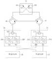
도 2는 본 발명의 제1 실시예에 따른 이동통신 시스템의 기지국 장치의 블록 구성도로서, 도 2에는 도 1에 도시된 종래의 예와 유사하게, 일반적인 이동통신 기지국에서 사용하는 2T2R MIMO 구조의 안테나 시스템(10)과, 이의 각 송수신 경로에 제공되는 제1 및 제2 듀플렉서(20, 21)가 개시되고 있다. 안테나 시스템(10)에는 2T2R 구조에서 제1경로(P0)에 대한 신호를 송신 및 수신하는 제1 안테나(Ant0; 100)와, 제2경로(P1)에 대한 신호를 송신 및 수신하는 제2 안테나(Ant1; 101)가 구비되며, 제1 및 제2 안테나(100, 101)는 서로 직교하는 편파를 발생하게 설치된다.FIG. 2 is a block diagram of a base station apparatus in a mobile communication system according to a first embodiment of the present invention. FIG. 2 is a 2T2R MIMO structure used in a general mobile communication base station, similar to the conventional example shown in FIG. 1. An antenna system (10) and first and second duplexers (20, 21) provided for each transmission/reception path thereof are disclosed. The
이러한 구성에서 본 발명의 특징에 따라, 안테나 시스템(10)의 제1 안테나(100)는 제2 안테나(101)와, 제1 및 제2 듀플렉서(20, 21) 사이에는, 제1 및 제2 송수신 신호 경로를 변경하여, 제1 듀플렉서(20)에서 제공되는 송신 신호는 제1 안테나(100)로 제공하며, 제1 안테나(100)에서 제공되는 수신 신호는 제2 듀플렉서(21)로 제공하며, 제2 듀플렉서(21)에서 제공되는 송신 신호는 제2 안테나(101)로 제공하며, 제2 안테나(101)에서 제공되는 수신 신호는 제1 듀플렉서(20)로 제공하는 경로 변경부가 구비된다. 제1 서큘레이터(40) 및 제2 서큘레이터(41)의 쌍으로 구성될 수 있다.According to the features of the present invention in this configuration, the
보다 상세한 구성을 보면, 제1 서큘레이터(40)는 1번 단자를 통해 제1 듀플렉서(20)와 연결되며, 2번 단자는 제1 안테나(100)와 연결되며, 3번 단자는 제2 서큘레이터(41)의 3번 단자와 연결되도록 설치되며, 1번 단자를 통해 입력된 신호는 2번 단자를 통해 출력되며, 2번 단자를 통해 입력된 신호는 3번 단자를 통해 출력되며, 3번 단자를 통해 입력된 신호는 1번 단자를 통해 출력된다.Looking at a more detailed configuration, the
제2 서큘레이터(41)는 1번 단자를 통해 제2 듀플렉서(21)와 연결되며, 2번 단자는 제2 안테나(101)와 연결되며, 3번 단자는 제1 서큘레이터(40)의 3번 단자와 연결되도록 설치되며, 1번 단자를 통해 입력된 신호는 2번 단자를 통해 출력되며, 2번 단자를 통해 입력된 신호는 3번 단자를 통해 출력되며, 3번 단자를 통해 입력된 신호는 1번 단자를 통해 출력된다.The
또한, 종래와 유사하게, 안테나 시스템(10)의 제1 및 제2 안테나(100, 101)와 각각 연결되어, 각각 제1 및 제2경로(P0, P1)의 송수신 신호를 분리 또는 결합하기 위한 제1 및 제2 듀플렉서(20, 21)가 구비되는데, 제1 듀플렉서(20)는 제1 송수신부(P0송수신부)(30)의 송신 신호를 처리하는 송신 필터(204)와 더불어, 종래와는 달리, 제2 송수신부(P1송수신부)(31)의 수신 신호를 처리하는 수신 필터(206')를 구비한다. 즉, 제1 및 제2경로의 송수신 신호의 주파수 대역이 동일하므로, 실질적으로 제1 듀플렉서(20)의 하드웨어적인 구조는 상기 도 1에 도시된 종래의 구조와 동일할 수 있으나, 수신 필터(206')가 제2 송수신부(31)와 연결되며, 제2 경로의 수신 신호를 필터링하는데 사용된다.In addition, similar to the prior art, it is connected to the first and
마찬가지로, 제2 듀플렉서(21)는 제2 송수신부(P1송수신부)(31)의 송신 신호를 처리하는 송신 필터(214)와, 제1 송수신부(30)의 수신 신호를 처하는 수신 필터(216')를 구비한다. 즉, 제2 듀플렉서(21)는 수신 필터(216')가 제1 송수신부(30)와 연결되며, 제1 경로의 수신 신호를 필터링하는데 사용된다.Similarly, the
제1 듀플렉서(20)는 제1경로에 대한 송신 신호를 처리하는 송신필터(204)와, 제2경로에 대한 수신 신호를 처리하는 수신필터(206')가 T-정션(T-junction)(202)을 이용하여 연결하는 구조를 가지며, 제2 듀플렉서(21)는 제2경로에 대한 송신 신호를 처리하는 송신필터(214)와, 제1경로에 대한 수신 신호를 처리하는 수신필터(216'가 T-정션(212)을 이용하여 연결하는 구조를 가진다.
The
상기한 구조에 의해, 제1 듀플렉서(20)의 제1경로의 송신필터(204)에서 송신된 신호는 제1 서큘레이터(40)를 거쳐 안테나 시스템(10)의 제1 안테나(100)로 제공되어 공중(air)으로 방사된다. 공중에서 제1경로의 수신 신호는 제1 안테나(101)에서 수신되어 제1 서큘레이터(40)를 거쳐 제2 서큘레이터(41)로 제공된 후, 제2 듀플렉서(21)의 제1경로의 수신필터(216')에 제공된다. 이때 제1 경로의 송신신호와 수신신호는 제1 듀플렉서(20) 및 제2 듀플렉서(21)에 의해 분리되어 완벽한 격리도를 갖게 된다.With the above-described structure, the signal transmitted from the
마찬가지로, 제2 듀플렉서(21)의 제2경로의 송신필터(214)에서 송신된 신호는 제2 서큘레이터(41)를 거쳐 안테나 시스템(10)의 제2 안테나(101)로 제공되어 공중(air)으로 방사된다. 공중에서 제2경로의 수신 신호는 제2 안테나(101)로 수신되어 제2 서큘레이터(41)로 제공되고, 제2 서큘레이터(41)에서 제1 서큘레이터(40)로 제공된 후, 제1 듀플렉서(20)의 제1경로의 수신필터(206')로 제공된다. 이때 제2 경로의 송신신호와 수신신호는 제1 듀플렉서(20) 및 제2 듀플렉서(21)에 의해 분리되어 완벽한 격리도를 갖게 된다.Similarly, the signal transmitted from the
상기 도 2에 도시된 구조를 살펴보면, 본 발명에 따른 장치는 서큘레이터들(40, 41)의 방향성을 이용하여 2T2R(또는 동등 이상) MIMO 기지국에서 송신단과 수신단의 격리도를 증가시키는 구조임을 알 수 있다.Looking at the structure shown in FIG. 2, it can be seen that the device according to the present invention is a structure for increasing the isolation between the transmitting end and the receiving end in a 2T2R (or equivalent or higher) MIMO base station using the directionality of the
보다 상세히 설명하면, 하나의 안테나 시스템(10)에서 제1 및 제2 안테나(100, 101)는 서로 90도로 직교되게 설치되어, 공중(air)으로 신호를 송수신할 때에, 안테나들(100, 101)간의 직교(orthogonal) 특성으로 인하여, 각 안테나들(100, 101)간의 송수신 신호는 통상 30dB 수준의 격리도를 얻게 된다.In more detail, in one
이때, 예를 들어, 제2경로의 수신필터(206')는 T-정션(212)에 의해 제1경로의 송신필터(204)와 묶여 있기 때문에, 제1경로의 송신필터(204)의 격리 특성에 의해 격리도가 결정된다. 그런데, 제1경로의 송신 필터(204)와, 제2경로의 수신필터(206')은 각각 결과적으로 제1 안테나(100) 및 제2 안테나(101)와 연결되어 있으므로, 이 두 안테나들(100, 101)들의 직교 특성에 의해 약 30dB 수준의 격리도를 갖게 된다. 따리서 제1경로의 송신 신호와 제2 경로의 수신 신호는 각 송수신 필터들(204, 206')의 격리도에 추가로 안테나들(100, 101)의 격리도 30dB를 얻게 된다. 제2 경로의 송신 신호와 제1 경로의 수신 신호도 마찬가지로 해당 송수신 필터들(214, 216')의 격리도에 추가로 안테나들(100, 101)의 격리도를 얻게 된다.At this time, for example, since the reception filter 206' of the second path is tied to the
상기한 바와 같이, 본 발명에서는 송신 신호 및 수신 신호간의 격리도가 듀플렉서의 고유의 격리도 외에도, 안테나들의 직교 특성에 의해 얻어지는 30dB 수준의 추가적인 송수신 신호 격리도를 얻게 된다. 이에 따라, 송신 신호 및 수신 신호간에 요구되는 격리도가 예를 들어 90dB일 경우에, 본 발명에서는 듀플렉서에서 60dB 수준의 격리도만 만족시키도록 구현하는 것이 가능하다. 이에 비해, 종래에는 듀플렉서만을 이용하여 90dB의 격리도를 만족시켜야 하므로, 듀플렉서의 구현시 구조 및 사이즈 측면에서 보다 큰 어려움이 있게 된다.
As described above, in the present invention, in addition to the inherent isolation level of the duplexer, the isolation level between the transmission signal and the reception signal is obtained by additional transmission/reception signal isolation level of 30 dB obtained by orthogonal characteristics of the antennas. Accordingly, when the required isolation level between the transmission signal and the reception signal is, for example, 90 dB, in the present invention, it is possible to implement to satisfy only the isolation level of 60 dB in the duplexer. On the other hand, conventionally, since the isolation level of 90 dB must be satisfied using only the duplexer, there is a greater difficulty in terms of structure and size when implementing the duplexer.
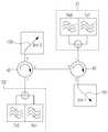
도 3은 본 발명의 제2 실시예에 따른 이동통신 시스템의 기지국 장치의 블록 구성도이다. 도 3에 도시된 제2 실시예에 따른 구조는 도 2에 도시된 제1 실시예의 구조와 대부분 동일하나, 제1 및 제2 듀플렉서(20, 21)에서 각각의 내부의 송신 필터 및 수신 필터의 신호를 분배 및 결합하는 구조에서 차이를 가진다.3 is a block diagram of a base station apparatus in a mobile communication system according to a second embodiment of the present invention. The structure according to the second embodiment shown in FIG. 3 is mostly the same as the structure of the first embodiment shown in FIG. 2, but the first and
상기 도 2에 도시된 제1 실시예에서는 예를 들어, 제1 듀플렉서(20)는 송신필터(204)와, 수신필터(206')가 T-정션(202)을 이용하여 연결하는 구조를 가짐에 비해, 도 3에 도시된 제2 실시예에서는 상기 T-정션(202) 대신에 제3 서큘레이터(203)를 사용한다. 보다 상세한 구성을 보면, 도 3에 도시된 제1 듀플렉서(20)에서, 제3 서큘레이터(203)는 1번 단자를 통해 송신 필터(204)와 연결되며, 2번 단자는 제1 서큘레이터(40)의 1번 단자와 연결되며, 3번 단자는 수신 필터(206')와 연결되도록 설치된다. 이때 제3 서큘레이터(203)의 1번 단자를 통해 입력된 신호는 2번 단자를 통해 출력되며, 2번 단자를 통해 입력된 신호는 3번 단자를 통해 출력된다.In the first embodiment shown in FIG. 2, for example, the
마찬가지로, 제2 듀플렉서(21)에서는, 송신필터(214)와, 수신필터(216')가 제4 서큘레이터(205)를 사용하여 연결되는 구조를 가지는데, 제4 서큘레이터(205)는 1번 단자를 통해 송신 필터(214)와 연결되며, 2번 단자는 제2 서큘레이터(41)의 1번 단자와 연결되며, 3번 단자는 수신 필터(216')와 연결되도록 설치된다. 제4 서큘레이터(205)의 1번 단자를 통해 입력된 신호는 2번 단자를 통해 출력되며, 2번 단자를 통해 입력된 신호는 3번 단자를 통해 출력된다.Similarly, in the
상기 도 3에 도시된 실시예에서는, 예를 들어 제1경로의 송신 신호와 제2 경로의 수신 신호는 제3 서큘레이터(203)를 지나면서 서큘레이터 고유의 격리도 약 20dB를 추가로 얻게 된다. 또한 이 신호는 안테나 시스템(10)의 분리도 30dB를 추가로 얻게 되어, 전체적으로 약 50dB의 분리도를 추가로 얻을 수 있게 된다. 마찬가지로, 제2경로의 송신 신호의 제1경로의 수신신호도 약 50dB의 분리도를 추가로 얻게 된다.
In the embodiment illustrated in FIG. 3, for example, the transmission signal of the first path and the reception signal of the second path pass through the
도 4는 본 발명의 제3 실시예에 따른 이동통신 시스템의 기지국 장치의 블록 구성도이다. 도 4에 도시된 제3 실시예에 따른 구조는 도 2에 도시된 제1 실시예의 구조와 대부분 동일하나, 제2 듀플렉서(21) 대신에, 제1경로의 수신 필터(23)가 제2서큘레이터(41)의 1번 단자에 연결되는 구조에서 차이가 있다. 이러한 도 4에 도시된 구조는 도 2에 도시된 제1 실시예에 따른 구조와 비교하여 제2경로의 송신 신호의 처리에 관한 구성 및 동작을 가지지 않는다는 점을 제외하고 도 2에 도시된 제1 실시예의 구성 및 동작과 동일하다. 즉, 상기 도 2 및 도 3에 도시된 제1 및 제2 실시예의 구조는 2T2R MIMO 방식을 구현하기 위해 적용된 구조이나, 도 4에 도시된 구조는 1T2R MIMO 방식을 구현하기 위한 구조임을 알 수 있다.
4 is a block diagram of a base station apparatus in a mobile communication system according to a third embodiment of the present invention. The structure according to the third embodiment shown in FIG. 4 is mostly the same as the structure of the first embodiment shown in FIG. 2, but instead of the
도 5는 본 발명의 제4 실시예에 따른 이동통신 시스템의 기지국 장치의 블록 구성도이다. 도 5에 도시된 제4 실시예에 따른 구조는 실질적으로, 상기 도 4에 도시된 제3 실시예의 구조를 이중으로 채용한 구조이다. 즉, 도 5에 도시된 구조는 도 4에 도시된 1T2R MIMO 방식을 이중으로 구비하여 2T4R MIMO 방식을 구현하기 위한 구조임을 알 수 있다.
5 is a block diagram of a base station apparatus in a mobile communication system according to a fourth embodiment of the present invention. The structure according to the fourth embodiment shown in FIG. 5 is substantially a structure in which the structure of the third embodiment shown in FIG. 4 is dually adopted. That is, it can be seen that the structure shown in FIG. 5 is a structure for implementing the 2T4R MIMO method by providing the 1T2R MIMO method shown in FIG.
도 6a 및 도 6b는 본 발명의 실시예들에 대한 변형 예이다. 예를 들어, 도 2에 도시된 제1 실시예에서는, 제1 서큘레이터(20)의 방향성이 순방향(시계방향)이며, 제2서큘레이터(21)의 방향성이 역방향(반시계방향)인 것으로 도시되고 있다. 그런데, 실제 제품 구현시는 순방향인 두 서큘레이터의 조합으로 구현하는 것이 가능하다.6A and 6B are modified examples of embodiments of the present invention. For example, in the first embodiment shown in FIG. 2, the directionality of the
도 6a에 도시한 바와 같이, 순방향인 서큘레이터(a, b)의 조합된 쌍은 전체적으로 4개의 신호 순환 전달 단자를 가지는 비가역 회로 구조(nonreciprocal circuit topology)를 가진다. 이러한 구조에서 도 6b에 도시된 바와 같이, 순방향 서큘레이터 쌍(40, 42)의 각 단자에 제1 듀플렉서(20), 제1 안테나(100), 제2 듀플렉서(21), 제2 안테나(101)를 연결하여, 상기 도 2 도시된 제1 실시예의 구조와 논리적으로 동일한 구조를 구현할 수 있게 된다.
As shown in FIG. 6A, the combined pair of forward circulators (a, b) has a nonreciprocal circuit topology with four signal circulation transfer terminals as a whole. In this structure, as shown in Figure 6b, the
상기와 같이 본 발명의 일 실시예에 따른 송신 신호 및 수신 신호간의 격리도 제공 장치가 구성될 수 있으며, 한편 상기한 본 발명의 설명에서는 구체적인 실시예에 관해 설명하였으나 여러 가지 변형이 본 발명의 범위를 벗어나지 않고 실시될 수 있다.As described above, an apparatus for providing isolation between a transmission signal and a reception signal according to an embodiment of the present invention may be configured. Meanwhile, in the above description of the present invention, specific embodiments have been described, but various modifications are provided in the scope of the present invention. It can be carried out without deviating.
예를 들어, 상기의 설명에서는 안테나 시스템(10)에서 두 안테나가 서로 직교하는 편파를 발생하도록 설치되므로 격리도를 얻는 것으로 설명하였으나, 이외에도 두 안테나는 서로 직교하지는 않으나, 공간적으로 적절한 거리를 가지도록 이격되게 설치되어 분리도를 확보하는 구조를 가지도록 구성될 수도 있다.For example, in the above description, the
또한, 상기 도 2 및 도 3에 도시된 제1 및 제2 실시예에서는 2T2R MIMO 방식에 해당하는 구조를 개시하고 있으나, 이러한 구조를 이중(또는 그 이상의 다중)으로 사용하여 4T4R(또는 그 이상의) MIMO 방식을 구현하는 것도 가능하다.In addition, although the structures corresponding to the 2T2R MIMO scheme are disclosed in the first and second embodiments shown in FIGS. 2 and 3, 4T4R (or more) using these structures in dual (or more multiples) It is also possible to implement MIMO.
또한, 상기 도 4 및 도 5에서 도시된 제3 및 제4 실시예에서는 듀플렉서들의 구조가 T-정션 구조를 이용하여 구현되는 것으로 도시되었으나, 이외에도 해당 듀플렉서들의 구조는 도 3과 같이 서큘레이터를 이용한 구조를 채용할 수도 있다.In addition, in the third and fourth embodiments shown in FIGS. 4 and 5, the structures of the duplexers are shown to be implemented using a T-junction structure, but the structures of the duplexers are circulatored as shown in FIG. The structure can also be employed.
이와 같이 본 발명의 다양한 변형 및 변경이 있을 수 있으며, 따라서 본 발명의 범위는 설명된 실시예에 의하여 정할 것이 아니고 청구범위와 청구범위의 균등한 것에 의하여 정하여져야 할 것이다.As such, there may be various modifications and variations of the present invention, and therefore, the scope of the present invention should not be determined by the described embodiments, but should be determined by the equivalents of the claims and claims.
Claims (6)
Translated fromKoreanMIMO(Multi Input Multi Output) 경로 중 제1경로에 대한 신호를 송수신하는 제1 안테나와, MIMO 경로중 제2경로에 대한 신호를 송수신하는 제2 안테나를 구비하는 안테나 시스템과;
상기 제1경로의 송신 신호를 처리하는 송신 필터와, 상기 제2경로의 수신 신호를 처리하는 수신 필터를 구비하는 제1 듀플렉서와;
상기 제1경로의 수신 신호를 처리하는 수신 필터와, 상기 제2경로의 송신 신호를 처리하는 송신 필터를 구비하는 제2 듀플렉서와;
상기 제1 듀플렉서에서 제공되는 송신 신호는 상기 제1 안테나로 제공하며, 상기 제1 안테나에서 제공되는 수신 신호는 상기 제2 듀플렉서로 제공하며, 상기 제2 듀플렉서에서 제공되는 송신 신호는 상기 제2 안테나로 제공하며, 상기 제2 안테나에서 제공되는 수신 신호는 상기 제1 듀플렉서로 제공하는 경로 변경부를 포함하며;
상기 제1 듀플렉서 및 제2 듀플렉서는 내부 송수신 필터들을 서큘레이터를 이용하여 연결하는 구조를 가짐을 특징으로 하는 기지국 장치.
In the base station apparatus of a mobile communication system,
An antenna system having a first antenna for transmitting and receiving a signal for a first path in a multi input multi output (MIMO) path, and a second antenna for transmitting and receiving a signal for a second path in a MIMO path;
A first duplexer having a transmission filter for processing the transmission signal of the first path and a reception filter for processing the reception signal of the second path;
A second duplexer having a reception filter for processing the received signal of the first path and a transmission filter for processing the transmitted signal of the second path;
The transmission signal provided by the first duplexer is provided to the first antenna, the reception signal provided from the first antenna is provided to the second duplexer, and the transmission signal provided from the second duplexer is the second antenna. Provided, the received signal provided by the second antenna includes a path changer provided to the first duplexer;
The first duplexer and the second duplexer base station apparatus characterized in that it has a structure for connecting the internal transmission and reception filters using a circulator.
상기 제1 서큘레이터에서 1번, 2번 및 3번 단자는 각각 상기 제1 듀플렉서, 상기 제1 안테나 및 상기 제2 서큘레이터의 3번 단자와 연결되며, 상기 제1 서큘레이터에서 1번 단자를 통해 입력된 신호는 2번 단자를 통해 출력되며, 2번 단자를 통해 입력된 신호는 3번 단자를 통해 출력되며, 3번 단자를 통해 입력된 신호는 1번 단자를 통해 출력되며;
상기 제2 서큘레이터에서 1번, 2번 및 3번 단자는 각각 상기 제2 듀플렉서, 상기 제2 안테나 및 상기 제1 서큘레이터의 3번 단자와 연결되며, 상기 제2 서큘레이터에서, 1번 단자를 통해 입력된 신호는 2번 단자를 통해 출력되며, 2번 단자를 통해 입력된 신호는 3번 단자를 통해 출력되며, 3번 단자를 통해 입력된 신호는 1번 단자를 통해 출력됨을 특징으로 하는 기지국 장치.
The method of claim 1, wherein the path changing unit comprises a first circulator and a second circulator;
Terminals 1, 2, and 3 in the first circulator are respectively connected to terminals 3 of the first duplexer, the first antenna, and the second circulator, and the terminal 1 in the first circulator. The signal input through is output through terminal 2, the signal input through terminal 2 is output through terminal 3, and the signal input through terminal 3 is output through terminal 1;
In the second circulator, terminals 1, 2, and 3 are respectively connected to terminals 3 of the second duplexer, the second antenna, and the first circulator, and in the second circulator, terminals 1 The signal input through is output through terminal 2, the signal input through terminal 2 is output through terminal 3, and the signal input through terminal 3 is output through terminal 1. Base station device.
The base station apparatus according to claim 1 or 2, wherein the first and second antennas are installed to generate polarizations orthogonal to each other.
MIMO(Multi Input Multi Output) 경로 중 제1경로에 대한 신호를 송수신하는 제1 안테나와, MIMO 경로중 제2경로에 대한 신호를 수신하는 제2 안테나를 구비하는 안테나 시스템과;
상기 제1경로의 송신 신호를 처리하는 송신 필터와, 상기 제2경로의 수신 신호를 처리하는 수신 필터를 구비하는 듀플렉서와;
상기 제1경로의 수신 신호를 처리하는 수신 필터와;
상기 듀플렉서에서 제공되는 송신 신호는 상기 제1 안테나로 제공하며, 상기 제1 안테나에서 제공되는 수신 신호는 상기 수신 필터로 제공하며, 상기 제2 안테나에서 제공되는 수신 신호는 상기 듀플렉서로 제공하는 경로 변경부를 포함하며;
상기 듀플렉서는 내부 송수신 필터들을 서큘레이터를 이용하여 연결하는 구조를 가짐을 특징으로 하는 기지국 장치.
In the base station apparatus of a mobile communication system,
An antenna system having a first antenna for transmitting and receiving a signal for a first path among multi input multi output (MIMO) paths, and a second antenna for receiving a signal for a second path among MIMO paths;
A duplexer having a transmission filter for processing the transmission signal of the first path and a reception filter for processing the reception signal of the second path;
A receiving filter for processing the received signal of the first path;
The transmission signal provided from the duplexer is provided to the first antenna, the received signal provided from the first antenna is provided to the reception filter, and the received signal provided from the second antenna is changed to a path provided to the duplexer Includes wealth;
The duplexer is a base station apparatus characterized in that it has a structure for connecting the internal transmission and reception filters using a circulator.
상기 제1 서큘레이터에서 1번, 2번 및 3번 단자는 각각 상기 듀플렉서, 상기 제1 안테나 및 상기 제2 서큘레이터의 3번 단자와 연결되며, 상기 제1 서큘레이터에서 1번 단자를 통해 입력된 신호는 2번 단자를 통해 출력되며, 2번 단자를 통해 입력된 신호는 3번 단자를 통해 출력되며, 3번 단자를 통해 입력된 신호는 1번 단자를 통해 출력되며;
상기 제2 서큘레이터에서 1번, 2번 및 3번 단자는 각각 상기 수신 필터, 상기 제2 안테나 및 상기 제1 서큘레이터의 3번 단자와 연결되며, 상기 제2 서큘레이터에서, 1번 단자를 통해 입력된 신호는 2번 단자를 통해 출력되며, 2번 단자를 통해 입력된 신호는 3번 단자를 통해 출력되며, 3번 단자를 통해 입력된 신호는 1번 단자를 통해 출력됨을 특징으로 하는 기지국 장치.
The method of claim 4, wherein the path changing unit comprises a first circulator and a second circulator;
In the first circulator, terminals 1, 2, and 3 are respectively connected to terminals 3 of the duplexer, the first antenna, and the second circulator, and input through the terminal 1 in the first circulator. The output signal is output through terminal 2, the signal input through terminal 2 is output through terminal 3, and the signal input through terminal 3 is output through terminal 1;
In the second circulator, terminals 1, 2, and 3 are respectively connected to terminals 3 of the receiving filter, the second antenna, and the first circulator, and in the second circulator, the terminals 1 The base station characterized in that the signal input through is output through terminal 2, the signal input through terminal 2 is output through terminal 3, and the signal input through terminal 3 is output through terminal 1. Device.
Priority Applications (1)
| Application Number | Priority Date | Filing Date | Title |
|---|---|---|---|
| KR1020130073692AKR102128604B1 (en) | 2013-06-26 | 2013-06-26 | Base station apparatus for mobile communication system |
Applications Claiming Priority (1)
| Application Number | Priority Date | Filing Date | Title |
|---|---|---|---|
| KR1020130073692AKR102128604B1 (en) | 2013-06-26 | 2013-06-26 | Base station apparatus for mobile communication system |
Publications (2)
| Publication Number | Publication Date |
|---|---|
| KR20150001065A KR20150001065A (en) | 2015-01-06 |
| KR102128604B1true KR102128604B1 (en) | 2020-06-30 |
Family
ID=52474920
Family Applications (1)
| Application Number | Title | Priority Date | Filing Date |
|---|---|---|---|
| KR1020130073692AActiveKR102128604B1 (en) | 2013-06-26 | 2013-06-26 | Base station apparatus for mobile communication system |
Country Status (1)
| Country | Link |
|---|---|
| KR (1) | KR102128604B1 (en) |
Family Cites Families (4)
| Publication number | Priority date | Publication date | Assignee | Title |
|---|---|---|---|---|
| KR20040107176A (en)* | 2003-06-13 | 2004-12-20 | (주)티알에프 | High Quality of Wave is to Repeater with Diversity |
| KR101010814B1 (en)* | 2005-03-31 | 2011-01-25 | 에스케이 텔레콤주식회사 | Integrated wireless repeater |
| JP4879083B2 (en)* | 2007-05-07 | 2012-02-15 | 株式会社エヌ・ティ・ティ・ドコモ | Leakage power reduction device and reduction method |
| KR101085892B1 (en)* | 2009-09-21 | 2011-11-23 | 주식회사 케이엠더블유 | Wireless communication base station common device |
- 2013
- 2013-06-26KRKR1020130073692Apatent/KR102128604B1/enactiveActive
Also Published As
| Publication number | Publication date |
|---|---|
| KR20150001065A (en) | 2015-01-06 |
Similar Documents
| Publication | Publication Date | Title |
|---|---|---|
| US10680790B2 (en) | Antenna system | |
| JP2017529767A (en) | Carrier aggregation device | |
| US11043754B2 (en) | Method and apparatus for multi-feed multi-band MIMO antenna system | |
| US10454505B2 (en) | Multi-frequency transceiver and base station | |
| EP2891210A1 (en) | A wireless communication node with antenna arrangement for dual band reception and transmission | |
| US20190044547A1 (en) | Wireless communication node with multi-band filters | |
| US9917627B2 (en) | Base station device in mobile communication system and circulator arrangement to increase isolation between co-located antennas | |
| US9800301B2 (en) | Antenna sharing device for wireless access node systems in wireless communication network | |
| US20180248240A1 (en) | Compact antenna feeder with dual polarization | |
| KR102128606B1 (en) | Base station apparatus for mobile communication system | |
| US20170214152A1 (en) | Active Dual Antenna Arrangement | |
| KR102128604B1 (en) | Base station apparatus for mobile communication system | |
| JP6409129B2 (en) | Base station apparatus for mobile communication system | |
| US10044103B2 (en) | Wireless communication node with an antenna arrangement for triple band reception and transmission | |
| KR102058060B1 (en) | Apparatus for sharing antenna of wireless access node in wireless communication network |
Legal Events
| Date | Code | Title | Description |
|---|---|---|---|
| PA0109 | Patent application | Patent event code:PA01091R01D Comment text:Patent Application Patent event date:20130626 | |
| PG1501 | Laying open of application | ||
| PA0201 | Request for examination | Patent event code:PA02012R01D Patent event date:20180621 Comment text:Request for Examination of Application Patent event code:PA02011R01I Patent event date:20130626 Comment text:Patent Application | |
| E902 | Notification of reason for refusal | ||
| PE0902 | Notice of grounds for rejection | Comment text:Notification of reason for refusal Patent event date:20191022 Patent event code:PE09021S01D | |
| E701 | Decision to grant or registration of patent right | ||
| PE0701 | Decision of registration | Patent event code:PE07011S01D Comment text:Decision to Grant Registration Patent event date:20200417 | |
| GRNT | Written decision to grant | ||
| PR0701 | Registration of establishment | Comment text:Registration of Establishment Patent event date:20200624 Patent event code:PR07011E01D | |
| PR1002 | Payment of registration fee | Payment date:20200624 End annual number:3 Start annual number:1 | |
| PG1601 | Publication of registration | ||
| PR1001 | Payment of annual fee | Payment date:20240312 Start annual number:5 End annual number:5 |