KR102126816B1 - Fingerprint recognition apparatus and method - Google Patents
Fingerprint recognition apparatus and methodDownload PDFInfo
- Publication number
- KR102126816B1 KR102126816B1KR1020130108162AKR20130108162AKR102126816B1KR 102126816 B1KR102126816 B1KR 102126816B1KR 1020130108162 AKR1020130108162 AKR 1020130108162AKR 20130108162 AKR20130108162 AKR 20130108162AKR 102126816 B1KR102126816 B1KR 102126816B1
- Authority
- KR
- South Korea
- Prior art keywords
- unit
- fingerprint recognition
- power
- fingerprint
- electronic device
- Prior art date
- Legal status (The legal status is an assumption and is not a legal conclusion. Google has not performed a legal analysis and makes no representation as to the accuracy of the status listed.)
- Expired - Fee Related
Links
Images


Classifications
- G—PHYSICS
- G06—COMPUTING OR CALCULATING; COUNTING
- G06F—ELECTRIC DIGITAL DATA PROCESSING
- G06F21/00—Security arrangements for protecting computers, components thereof, programs or data against unauthorised activity
- G06F21/30—Authentication, i.e. establishing the identity or authorisation of security principals
- G06F21/31—User authentication
- G06F21/32—User authentication using biometric data, e.g. fingerprints, iris scans or voiceprints
- G—PHYSICS
- G06—COMPUTING OR CALCULATING; COUNTING
- G06V—IMAGE OR VIDEO RECOGNITION OR UNDERSTANDING
- G06V40/00—Recognition of biometric, human-related or animal-related patterns in image or video data
- G06V40/10—Human or animal bodies, e.g. vehicle occupants or pedestrians; Body parts, e.g. hands
- G06V40/12—Fingerprints or palmprints
- G06V40/13—Sensors therefor
- G06V40/1306—Sensors therefor non-optical, e.g. ultrasonic or capacitive sensing
- G—PHYSICS
- G06—COMPUTING OR CALCULATING; COUNTING
- G06V—IMAGE OR VIDEO RECOGNITION OR UNDERSTANDING
- G06V40/00—Recognition of biometric, human-related or animal-related patterns in image or video data
- G06V40/10—Human or animal bodies, e.g. vehicle occupants or pedestrians; Body parts, e.g. hands
- G06V40/12—Fingerprints or palmprints
Landscapes
- Engineering & Computer Science (AREA)
- Theoretical Computer Science (AREA)
- Physics & Mathematics (AREA)
- General Physics & Mathematics (AREA)
- Human Computer Interaction (AREA)
- Multimedia (AREA)
- Computer Security & Cryptography (AREA)
- Computer Hardware Design (AREA)
- Software Systems (AREA)
- General Engineering & Computer Science (AREA)
- Image Input (AREA)
- Measurement Of The Respiration, Hearing Ability, Form, And Blood Characteristics Of Living Organisms (AREA)
Abstract
Translated fromKoreanDescription
Translated fromKorean본 발명은 지문 인식 장치 및 방법, 그리고 이를 구비한 전자 장치에 관한 것이다.The present invention relates to a fingerprint recognition device and method, and an electronic device having the same.
최근 휴대용 전자 장치, 스마트폰 및 테블렛 PC, MP3 플레이어, PMP(Portable Multimedia Player) 및 전자책 단말기와 다양한 전자 장치가 사용자에게 제공되고 있으며, 사용자는 이러한 다양한 전자 장치를 휴대하면서 다양한 콘텐츠를 접할 수 있다.Recently, portable electronic devices, smartphones and tablet PCs, MP3 players, portable multimedia players (PMPs) and e-book terminals and various electronic devices have been provided to users, and users can access various contents while carrying these various electronic devices. have.
특히, 이러한 전자 장치에 다양한 개인 정보, 특히 금융 정보 등이 저장되는 경우가 많아지고 있다. 이 경우 사용자의 개인 정보가 저장된 전자 장치가 분실하는 경우 금융 정보등의 해킹이 발생하여 2차 피해로 이어질 확률이 높다. 이를 방지하기 위해 패턴 인식 또는 비밀번호등과 같은 보완 기능이 전자 장치에 적용되고 있으나, 이 역시 해킹으로부터 자유롭지 않다는 문제점이 있다.In particular, various personal information, especially financial information, etc. are stored in such electronic devices. In this case, if the electronic device in which the user's personal information is stored is lost, hacking such as financial information is likely to lead to secondary damage. To prevent this, complementary functions such as pattern recognition or passwords are applied to electronic devices, but there is also a problem that they are not free from hacking.
따라서, 이러한 문제점을 해결하기 위해 상기 전자 장치에 지문 인식 장치를 적용하여 사용자 개개인 고유의 지문을 저장하고, 일치하지 않는 지문이 입력 시 전자 장치에 접근을 차단함으로써, 패턴 인식 또는 비밀 번호 등의 방법보다 우수한 보완 성능을 제공할 수 있었다.Therefore, in order to solve this problem, a fingerprint recognition device is applied to the electronic device to store a unique fingerprint of each user, and when an inconsistent fingerprint is input, access to the electronic device is blocked, such as pattern recognition or password. It could provide better complementary performance.
그런데, 종래의 전자 장치의 지문 인식 장치는 전자 장치의 디스플레이 장치와 같은 지문 인식창이 필요할 뿐만 아니라, 단지 사용자의 지문 인식 기능 이외에 다른 기능으로 사용할 수 없는 특징이 있었다. 즉, 종래의 지문 인식 장치는 사용자의 지문 인식을 위해 지문 인식창이 필요함으로 인해 소형의 전자 장치에 설치시 설치 위치가 자유롭지 못한 특징이 있었다.However, a fingerprint recognition device of a conventional electronic device not only requires a fingerprint recognition window such as a display device of an electronic device, but also has a feature that cannot be used for functions other than the user's fingerprint recognition function. That is, the conventional fingerprint recognition device has a feature in that the installation position is not free when installed in a small electronic device because a fingerprint recognition window is required for the user's fingerprint recognition.
더불어, 상기 지문 인식 장치를 소형의 전자 장치에 실장하는 구조이므로, 외부 충격 시 휴대용 전자 장치의 외관에 구비된 지문 인식 장치가 쉽게 손상되고, 이로인해 과전류 또는 발열이 발생되는 특징이 있었다.In addition, since the fingerprint recognition device is mounted on a small-sized electronic device, the fingerprint recognition device provided on the exterior of the portable electronic device is easily damaged during an external impact, thereby causing overcurrent or heat generation.
결국, 지문 인식 장치를 소형의 전자 장치에 자유롭게 설치함과 동시에 전자 장치의 다른 기능으로도 사용 가능하고, 지문 인식 장치가 파손되어 발생되는 과전류에 의한 발열을 방지하는 장치가 요구되고 있다.As a result, there is a need for a device that freely installs a fingerprint recognition device on a small electronic device and can be used for other functions of the electronic device, and prevents overheating due to an overcurrent generated when the fingerprint recognition device is damaged.
따라서, 본 발명의 다양한 실시예들에서는, 전자 장치에 사용자의 지문을 인식함과 동시에 키(예를 들어, 홈키 및 사이드키등)으로 사용 가능하도록 지문 인식 센서부를 구성함으로써, 기존의 전자 장치의 보안 인증 기능(예를 들어, 패턴 인식 또는 비밀 번호 등)이외에 추가 보안 인증기능으로 사용하여 전자 장치의 보완 기능을 더욱 향상시킬 수 있을 뿐만 아니라, 기존의 키 위치에 지문 인식 센서부를 설치하여 설치 위치를 자유롭게 할뿐만 아니라, 추가로 전자 장치의 키로 사용할 수 있도록 한 전자 장치의 지문 인식 장치를 제공할 수 있다.Accordingly, in various embodiments of the present invention, by configuring a fingerprint recognition sensor unit to recognize a user's fingerprint on the electronic device and to use it as a key (for example, a home key and a side key), the existing electronic device In addition to the security authentication function (for example, pattern recognition or password, etc.), it can be used as an additional security authentication function to further improve the complementary function of the electronic device. In addition to freeing, it is possible to provide a fingerprint recognition device for an electronic device that can be used as a key for an electronic device.
그리고 본 발명의 다양한 실시예들에서는, 지문 인식 장치의 발열을 방지하기 위한 전자 장치의 지문 인식 장치를 제공할 수 있다.Further, in various embodiments of the present invention, a fingerprint recognition device of an electronic device for preventing heat generation of the fingerprint recognition device may be provided.
또한, 본 발명의 다양한 실시예들에서는, 지문 인식 장치의 고장을 알리는 메시지를 출력하기 위한 전자 장치의 지문 인식 장치를 제공할 수 있다.Further, in various embodiments of the present invention, a fingerprint recognition device of an electronic device for outputting a message informing a failure of the fingerprint recognition device may be provided.
본 발명의 일 실시예에 따른 전자 장치는, 전자 장치는, 표시부, 제어부 및 지문 인식 감지부를 포함하며, 상기 지문 인식 감지부는 전원 차단부, 키버튼 및 상기 키버튼의 적어도 일부분에 구비된 지문 인식 센서 모듈을 포함하며, 상기 지문 인식 센서 모듈은 회로 기판, 상기 회로 기판의 제 1 면에 구비되어 지문을 감지하는 지문 감지부 및 상기 회로 기판의 제 2 면에 구비되는 돔 스위치부를 포함하며, 상기 전원 차단부는 상기 지문 인식 센서 모듈에 과전류가 인가된 것을 식별한 것에 응답하여, 상기 지문 인식 센서 모듈의 전원 차단을 나타내는 전원 차단 신호를 상기 제어부로 전송하도록 구성되며, 상기 제어부는 상기 전원 차단 신호가 수신된 것에 응답하여, 상기 지문 인식 센서 모듈에 인가되는 전원을 차단하도록 상기 전원 차단부를 제어하고, 상기 지문 인식 센서 모듈의 고장에 대한 메시지 정보를 표시하도록 상기 표시부를 제어하도록 구성될 수 있다.An electronic device according to an embodiment of the present invention, the electronic device includes a display unit, a control unit, and a fingerprint identification sensing unit, wherein the fingerprint identification sensing unit is provided with a power cut-off unit, a key button, and fingerprint recognition provided on at least a portion of the key button Includes a sensor module, the fingerprint recognition sensor module includes a circuit board, a fingerprint sensing unit provided on the first surface of the circuit board to detect fingerprints, and a dome switch unit provided on the second surface of the circuit board, wherein In response to identifying that the overcurrent is applied to the fingerprint recognition sensor module, the power cutoff unit is configured to transmit a power cutoff signal indicating power cutoff of the fingerprint recognition sensor module to the control unit, wherein the power cutoff signal is generated by the control unit. In response to the received, it may be configured to control the power cut-off unit to cut off the power applied to the fingerprint sensor module, and to control the display unit to display message information about the failure of the fingerprint sensor module.
또한, 본 발명의 또 다른 실시예에 따른 전자 장치에서 지문을 인식하는 방법은, 상기 전자 장치의 전원 차단부에 의해 키버튼의 적어도 일부분에 구비된 지문 인식 센서 모듈로 인가되는 과전류를 확인하는 동작, 상기 지문 인식 센서 모듈에 과전류가 인가된 것을 식별한 것에 응답하여, 상기 전원 차단부에 의해 상기 지문 인식 센서 모듈의 전원 차단을 나타내는 전원 차단 신호를 상기 제어부로 전송하는 동작, 상기 전자 장치의 제어부에 의해 상기 전원 차단 신호가 수신된 것에 응답하여, 상기 지문 인식 센서 모듈에 인가되는 전원을 차단하도록 상기 전원 차단부를 제어하는 동작 및 상기 제어부에 의해 상기 지문 인식 센서 모듈의 고장에 대한 메시지 정보를 표시하도록 상기 전자 장치의 표시부를 제어하는 동작을 포함할 수 있다.In addition, a method of recognizing a fingerprint in an electronic device according to another embodiment of the present invention includes: checking an overcurrent applied to a fingerprint recognition sensor module provided in at least a portion of a key button by a power cut-off unit of the electronic device , In response to identifying that the overcurrent is applied to the fingerprint sensor module, transmitting a power-off signal indicating the power-off of the fingerprint sensor module to the control unit by the power cut-off unit, the control unit of the electronic device In response to receiving the power-off signal by, the operation of controlling the power-off unit to cut off the power applied to the fingerprint sensor module and the control unit displays message information about the failure of the fingerprint sensor module In order to do so, it may include an operation of controlling the display of the electronic device.
삭제delete
본 발명의 다양한 실시 예들에 따르면, 전자 장치에 지문 인식 센서부를 구성하여 기존의 전자 장치에 제공되는 보완 인증기능(예를 들어, 패턴 인식 또는 비밀 번호 등)이외에 추가 보안 인증기능으로 사용할 수 있고, 이로인해 전자 장치의 보완 성능을 극대화하여 제품의 사용을 향상시킬 수 있을 뿐만 아니라, 더불어, 전자 장치에 키로 이루어지는 지문 인식 센서부를 구성하여 기존의 키 위치에 지문 인식 센서부의 설치가 가능하고, 이로인해 사용자의 지문 인식 센서부의 사용을 향상시킴은 물론, 지문 인식 센서부의 설치 위치를 자유롭게 할 수 있을 뿐만 아니라, 추가로 전자 장치의 키로도 사용할 수 있는 효과가 있다.According to various embodiments of the present invention, a fingerprint recognition sensor unit may be configured in an electronic device to be used as an additional security authentication function in addition to a supplementary authentication function (for example, pattern recognition or password) provided to an existing electronic device, This not only improves the use of the product by maximizing the complementary performance of the electronic device, but also makes it possible to install the fingerprint recognition sensor unit at an existing key position by configuring a fingerprint recognition sensor unit made of a key in the electronic device. In addition to improving the use of the user's fingerprint recognition sensor unit, it is possible to freely install the fingerprint recognition sensor unit, and additionally, it can be used as a key for an electronic device.
그리고 본 발명의 다양한 실시예들에 따르면, 전자 장치의 지문 인식 장치의 고장에 의한 지문 인식 장치의 발열을 방지하는 효과가 있다.Further, according to various embodiments of the present invention, there is an effect of preventing heat generation of the fingerprint recognition device due to a failure of the fingerprint recognition device of the electronic device.
또한, 본 발명의 다양한 실시예들에 따르면, 전자 장치의 지문 인식 장치의 고장을 인식하고, 사용자에게 지문 인식 장치의 고장을 알리는 메시지를 출력함으로써, 사용자의 편의성을 높이는 효과가 있다.In addition, according to various embodiments of the present invention, by recognizing the failure of the fingerprint recognition device of the electronic device, and outputting a message informing the user of the failure of the fingerprint recognition device, there is an effect of increasing user convenience.
도 1은 본 발명의 일 실시예에 따른 전자 장치의 지문 인식 장치의 구성을 나타낸 사시도.
도 2는 본 발명의 일 실시예에 따른 전자 장치의 지문 인식 장치의 구성 중 키를 나타낸 측면도.
도 3은 본 발명의 일 실시예에 따른 전자 장치의 지문 인식 장치의 구성 중 다른 실시예의 키를 나타낸 측면도.
도 4는 본 발명의 일 실시예에 따른 전자 장치의 지문 인식 장치의 사용 상태를 나타낸 정면도.
도 5는 본 발명의 일 실시예에 따른 전자 장치의 지문 인식 장치의 사용 상태를 나타낸 평면도.
도 6은 본 발명의 일 실시 예에 따른 전자 장치의 블록 구성도.
도 7은 본 발명의 일 실시 예에 따른 지문 인식 감지부의 블록 구성도.
도 8은 본 발명의 일 실시 예에 따른 전원 차단부에서 전원을 차단하는 흐름도.
도 9는 본 발명의 일 실시 예에 따른 제어부에서 지문 인식 센서부의 고장을 알리는 메시지를 출력하는 흐름도.
도 10은 본 발명의 일 실시 예에 따라 지문 인식 센서부의 고장을 알리는 메시지가 출력되는 화면을 도시한 도면.1 is a perspective view showing the configuration of a fingerprint recognition device of an electronic device according to an embodiment of the present invention.
Figure 2 is a side view showing a key in the configuration of the fingerprint recognition device of the electronic device according to an embodiment of the present invention.
3 is a side view showing a key of another embodiment of the configuration of the fingerprint recognition device of the electronic device according to an embodiment of the present invention.
4 is a front view showing a use state of a fingerprint recognition device of an electronic device according to an embodiment of the present invention.
5 is a plan view showing a use state of a fingerprint recognition device of an electronic device according to an embodiment of the present invention.
6 is a block diagram of an electronic device according to an embodiment of the present invention.
7 is a block diagram of a fingerprint recognition sensing unit according to an embodiment of the present invention.
8 is a flowchart of cutting off power in a power cutoff unit according to an embodiment of the present invention.
9 is a flowchart for outputting a message informing a failure of the fingerprint recognition sensor unit from the control unit according to an embodiment of the present invention.
10 is a diagram illustrating a screen on which a message informing a failure of the fingerprint recognition sensor unit is output according to an embodiment of the present invention.
이하, 첨부된 도면들에 기재된 내용들을 참조하여 본 발명에 따른 다양한 실시예들을 상세하게 설명한다. 다만, 본 발명이 다양한 실시 예들에 의해 제한되거나 한정되는 것은 아니다. 각 도면에 제시된 동일한 참조부호는 실질적으로 동일한 기능을 수행하는 부재를 나타낼 수 있다.Hereinafter, various embodiments according to the present invention will be described in detail with reference to the contents described in the accompanying drawings. However, the present invention is not limited or limited by various embodiments. The same reference numerals in each drawing may denote members that perform substantially the same function.
도 1은 본 발명의 일 실시예에 따른 전자 장치의 지문 인식 장치를 나타내는 사시도이다.1 is a perspective view illustrating a fingerprint recognition device of an electronic device according to an embodiment of the present invention.
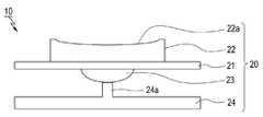
도 1을 참조하여 본 발명의 전자 장치(1)의 지문 인식 장치의 구성을 설명하면 다음과 같다. 먼저, 상기 지문 인식 장치(10)는 지문 인식 센서모듈(20)과, 전원 차단부(701)를 포함한다. 상기 전원 차단부(701)는 회로기판(21)에 구성될 수도 있다The configuration of the fingerprint recognition device of the
상기 지문 인식 센서모듈(20)은 상기 전자 장치에 구비되고, 사용자의 손가락 지문을 인식함과 동시에 전자 장치의 키로 이루어질 수 있다. 특히, 상기 키는 전자 장치의 홈키 또는 사이드키로 이루어질 수 있다. 상기 지문 인식 센서모듈(20)은 상기 홈키 또는 사이드키 이외에 다른 전자 장치의 키도 적용될 수 있다.The fingerprint
여기서, 본 실시예에서는 상기 전자 장치의 전면에 구비되는 홈키를 예로 적용하여 설명하기로 한다.Here, in this embodiment, the home key provided on the front surface of the electronic device will be described as an example.
따라서, 상기 지문 인식 센서모듈(20)이 전면에 위치함을 예를 들어 설명하나, 이에 한정되는 것을 아니다. 즉 상기 지문 인식 센서모듈(20)의 위치는 상기 전면 위치 이외에 상기 전자 장치(1)의 후면 또는 측면 위치에도 적용됨은 물론 전자 장치(1)의 다양한 위치에도 적용될 수 있다.Accordingly, the fingerprint
또한, 상기 지문 감지부(22)는 스와이프(Swipe) 방식의 지문 감지부(22) 또는 에어리어(Area) 방식들 중 어느 하나로 이루어질 수 있다. 물론, 상기 지문 인식 센서모듈(20)은 스와이프(Swipe) 방식 또는 에어리어(Area) 방식뿐만 아니라, 사용자의 지문을 인식하는 다른 방식의 센서도 사용될 수 있다.In addition, the
그리고, 상기 스와이프(Swipe) 방식의 지문 감지부(22)는 사용자의 손가락이 상기 센서부에서 미끄러지듯 움직일 때 사용자의 지문을 감지하는 구성이고, 상기 에어리어(Area) 방식은 사용자의 손가락 전체를 터치하여 감지하는 구성이다.And, the swipe (Swipe)
여기서, 본 실시예서는 상기 지문 감지부(22)로 스와이프(Swipe) 방식의 지문 감지부(22)를 적용하여 설명하기로 한다.Here, this embodiment will be described by applying the
이와 같이, 상기 지문 인식 센서모듈(20)은 기존의 홈키 위치에 설치됨과 동시에 추가로 홈키 기능으로 사용가능함으로써, 전자 장치내에서 지문 인식 센서부의 설치가 용이하고, 전자 장치의 홈키 본연의 기능을 유지함과 동시에 전자 장치(1)의 보안 기능으로도 사용할 수 있다.As described above, the fingerprint
여기서, 본 발명의 실시 예에 따른 상기 전자 장치(1; 도 1에 도시됨)의 적용예로는, 다양한 통신 시스템들에 대응되는 통신 프로토콜들에 의거하여 동작하는 모든 이동통신 단말기(mobile communication terminal) 및 휴대용 통신 기기를 비롯하여, PMP(Portable Multimedia Player), MP3 플레이어, 네비게이션, 게임기, 노트북, 넷북, 광고판, 티브이(TV), 디지털방송 플레이어, PDA(Personal Digital Assistant) 및 스마트 폰(Smart Phone) 등 모든 정보통신기기와 멀티미디어 기기 및 그에 대한 응용기기를 포함할 수 있다Here, as an application example of the electronic device 1 (shown in FIG. 1) according to an embodiment of the present invention, all mobile communication terminals operating based on communication protocols corresponding to various communication systems ) And portable communication devices, including portable multimedia players (PMPs), MP3 players, navigation, game consoles, notebooks, netbooks, billboards, TVs (TVs), digital broadcast players, PDAs (Personal Digital Assistants) and smart phones (Smart Phones) It may include all information and communication devices, multimedia devices, and application devices therefor.
여기서, 상기 지문 인식 센서모듈(20)의 구성을 좀 더 구체적으로 설명하면, 다음과 같다.Here, the configuration of the fingerprint
먼저, 도 2는 본 발명의 일 실시예에 따른 전자 장치의 지문 인식 장치의 구성 중 홈키의 구성을 나타낸 측면도 이고, 도 3은 본 발명의 일 실시예에 따른 전자 장치의 지문 인식 장치의 구성 중 홈키의 다른 실시예를 나타낸 측면도이다.First, FIG. 2 is a side view showing the configuration of a home key among the configurations of a fingerprint recognition device of an electronic device according to an embodiment of the present invention, and FIG. 3 is a configuration of a fingerprint recognition device of an electronic device according to an embodiment of the present invention It is a side view showing another embodiment of the home key.
도 2와 같이, 상기 지문 인식 센서모듈(20)은 회로 기판(21)과, 상기 지문 감지부(22)와, 돔 스위치부(23)를 포함한다. 상기 회로 기판(21)은 후술하는 지문 감지부(22) 및 돔 스위치부(23)와 전기적으로 연결될 수 있도록 상기 지문 감지부(22)와 상기 돔 스위치부(23)의 사이에 구비된다. 상기 지문 감지부(22)는 사용자의 지문을 감지할 수 있도록 상기 회로 기판(21)의 전면에 구비된다. 상기 돔 스위치부(23)는 상기 홈키로 사용할 수 있도록 상기 회로 기판(21)의 후면에 구비된다. 상기 키 안착부(24)은 상기 지문 감지부(22)를 누름에 따라서 상기 돔 스위치부(23)가 눌려질 수 있게 지지하도록 상기 돔 스위치부(23)의 하부에 구비된다.2, the fingerprint
상기 키 안착부(24)에는 상기 돔 스위치부(23)와 대면되고, 상기 지문 감지부(22)를 누를 경우 상기 돔 스위치부(23)를 가압하는 가압부(24a)가 구비된다.The
여기서, 상기 가압부(24a)는 가압 돌기로 이루어지고, 상기 가압 돌기는 상기 키 안착부(24)의 상면에서 돌출됨과 동시에 상기 돔 스위치의 하면과 접촉되도록 되어 있다. 물론, 상기 가압부(24a)는 상기 개시된 가압 돌기들 이외에 다른 종류의 볼록 형상의 돌기들이 적용될 수 있다.Here, the pressing portion (24a) is made of a pressing projection, the pressing projection is projected from the upper surface of the
이와 같이, 상기 가압부(24a)가 상기 키 안착부(24)에 돌출 형성함으로써, 상기 가압부(24a)가 상기 돔 스위치부(23)를 가압함과 동시에 상기 돔 스위치부(23)가 회로기판에 구비된 접점(미도시 됨)과 전기적으로 접촉되어 신호를 발생시킨다. 상기 발생된 신호는 상기 전자 장치의 제어부에 인가되어 상기 전자 장치(1)의 홈키 기능으로 사용된다.In this way, the
또한, 상기 가압부의 다른 실시예에 대해서 아래 도면들을 참조하여 좀 더 구체적으로 설명하면, 다음과 같다.In addition, another embodiment of the pressing part will be described in more detail with reference to the drawings below.
도 3은 본 발명의 가압부(23a)의 다른 실시예를 나타내는 측면도이다.3 is a side view showing another embodiment of the pressing portion 23a of the present invention.
먼저, 도 3과 같이, 상기 가압부(23a)는 상기 돔 스위치부(23)에 포함되어 하면에 돌출되고, 상기 키 안착부(24)의 상면과 접촉되도록 되어 있다.First, as shown in FIG. 3, the pressing portion 23a is included in the
즉, 상기 가압부(23a)는 상기 키 안착부(24)에 돌출 형성되는 것이 아니고, 상기 돔 스위치부(23)에 돌출 형성된다. 상기 지문 감지부(22)는 누르면, 상기 가압부(23a)는 상기 돔 스위치부(23)에 압력을 가해 눌려지게 한다.That is, the pressing portion 23a does not protrude from the
따라서, 상기 가압부(23a)는 상기 돔 스위치부(23)에 돌출 형성함으로써, 상기 가압부의 기능을 향상시킴은 물론, 전자 장치의 홈키 사용을 더욱 향상시킬 수 있다.Accordingly, the pressing portion 23a protrudes from the
또한, 앞서 언급한 도 1과 같이, 상기 지문 감지부(22)의 전면에는 홈키 데코부(30)가 구비될 수 있다. 상기 홈키 데코부(30)의 전면에는 상기 지문 인식 센서모듈(20)로 유입되는 습기를 차단하도록 포론부(Poron)(40)가 구비될 수 있다.In addition, as shown in FIG. 1 mentioned above, a home
더불어, 상기 지문 감지부(22)의 표면에는 상기 지문 인식 센서모듈(20)의 지문 인식 감지를 유지함과 동시에 외관을 미려하게 하도록 도장층(미도시 됨)이 구비될 수 있다. 즉, 상기 도장층(미도시 됨)은 UV 도장층으로 이루어질 수 있고, 상기 도장층은 다양한 칼라 도장층으로 이루어질 수 있다.In addition, a coating layer (not shown) may be provided on the surface of the
따라서, 상기 지문 감지부(22)의 표면은 상기 도장층에 의해 다양한 칼라로 이루어질 수 있다.Therefore, the surface of the
또한, 상기 도장층의 두께는 사용자의 지문 인식 성능을 유지하기 위해서 50㎛로 이루어질 수 있다. 물론, 상기 도장층의 두께는 사용자의 지문 인식 성능을 유지할 수 있다면, 앞서 개시한 50㎛의 이상 또는 이하도 적용될 수 있다.In addition, the thickness of the coating layer may be made of 50㎛ to maintain the fingerprint recognition performance of the user. Of course, if the thickness of the coating layer can maintain the fingerprint recognition performance of the user, 50 or more μm or less may be applied as described above.
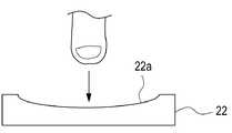
더불어, 도 4 및 도 5와 같이, 상기 지문 감지부(22)의 표면은 사용자의 지문 인식을 용이하게 하도록 가이드부(22a)가 형성될 수 있다. 상기 가이드부(22a)는 오목한 홈 형태로 형성될 수 있다. 상기 가이드부(22a)는 사용자의 지문 이미지를 획득하기 위해 가이드할 수 있다.In addition, as shown in FIGS. 4 and 5, the surface of the
즉, 도 4와 같이, 상기 가이드부(22a)의 중심부를 상기 지문 감지부(22)의 내측으로 들어가도록 형성하여 상기 지문 감지부(22)가 지문을 감지 시 사용자의 손가락의 각도를 상기 지문 감지부(22)의 중심이외에 다른 각도로 변경하여도 지문을 감지할 수 있다.That is, as shown in FIG. 4, the central portion of the
따라서, 도 5와 같이, 상기 가이드부(22a)는 사용자의 손가락 지문을 다양한 각도에서 감지할 수 있고, 이로인해 상기 지문 감지부(22)의 지문 오인식을 방지함은 물론 상기 지문 인식 장치의 기능을 향상시킬 수 있다.Thus, as shown in FIG. 5, the
이하에서는, 상기 지문 감지 장치의 동작 및 회로 동작 과정을 좀 더 구체적으로 설명하면, 다음과 같다.Hereinafter, the operation and circuit operation process of the fingerprint sensing device will be described in more detail.
먼저 앞서 언급한 도 1과 같이, 상기 지문 감지 장치(10)의 조립 과정을 설명하면, 상기 지문 감지 장치(10)는 전자 장치(1)에 구비되는 지문 인식 센서모듈(20)로 이루어지고, 상기 지문 인식 센서모듈(20)은 회로 기판(21)과, 지문 감지부(22)와, 돔 스위치부(23)를 포함한다. 상기 회로기판(21)의 전면에는 지문 감지부(22)가 구비하고, 상기 회로기판(21)의 후면에는 돔 스위치부(23)가 구비된다. 상기 돔 스위치부(23)는 상기 키 안착부(24)의 전면에 구비된다. 이때, 상기 돔 스위치부(23)는 상기 키 안착부(24)에 구비된 가압부(24a)와 대응되어 구비된다. 그리고, 상기 지문 감지부(22)의 전면에는 홈키 데코부(30)가 구비되고, 상기 홈키 데코부(30)의 전면에는 상기 프론부(Poron)(40)가 구비된다. 이와 같이 조립된 상기 지문 감지 장치(10)는 상기 전자 장치(1)의 전면에 구비된 홈키 안착홈(1a)에 장착한다.First, as described in FIG. 1, the assembly process of the
이 상태에서, 상기 사용자가 사용자의 손가락을 상기 지문 인식 센서모듈(20)의 지문 감지부(22)에 올려놓고, 미끄러지듯 상부에서 하부 또는 하부에서 상부로 움직일 경우 상기 지문 감지부(22)는 사용자의 지문을 감지한다. 그리고 상기 지문 감지부(22)는 감지된 지문을 이미지화함으로써 지문 이미지를 생성하여 상기 전자 장치의 제어부로 전송하고, 상기 제어부는 전송된 지문 이미지와 미리 저장된 사용자의 지문 이미지를 비교하고, 비교 결과를 기반으로 사용자를 인식할 수 있다. 이제부터, 도 6 내지 도 10을 참조하여 전자 장치의 동작을 설명하고자 한다.
In this state, when the user puts the user's finger on the
도 6은 본 발명의 일 실시 예에 따른 전자 장치의 블록 구성도이다.6 is a block diagram of an electronic device according to an embodiment of the present invention.
도 6을 참조하면, 전자 장치는 제어부(601)와 표시부(603)와 입력부(605)와 메모리부(607)와 전원부(609)와 지문 인식 감지부(611)를 포함할 수 있다.Referring to FIG. 6, the electronic device may include a control unit 601, a
각 구성요소를 살펴보면, 상기 입력부(605)는 숫자 및 문자 정보를 입력하기 위한 키들 및 각종 기능들을 설정하기 위한 기능 키들을 구비하고, 상기 표시부(603)는 영상 신호를 화면으로 표시하며, 상기 제어부(601)로부터 출력 요청되는 데이터를 표시할 수 있다. 만약에, 상기 표시부(603)가 정전식 또는 감압식 등의 터치 표시 화면 방식으로 구현될 경우, 상기 입력부(605)는 미리 설정된 최소한의 키만을 포함할 수 있으며 상기 표시부(603)는 상기 입력부(605)의 키입력 기능을 일부 대체할 수 있다.Looking at each component, the
그리고 상기 메모리부(607)는 프로그램 메모리와 데이터 메모리를 포함할 수 있다. 여기서, 상기 프로그램 메모리는 전자 장치의 일반적인 동작을 제어하기 위한 부팅(booting) 및 운영 시스템(Operating System, 이하 'OS'라 한다)을 저장하고, 상기 데이터 메모리는 전자 장치의 동작 중에 발생되는 각종 데이터들을 저장할 수 있다. 그리고 상기 전원부(609)는 제어부(601)의 제어에 따라 전자 장치의 각종 부품에 배터리(battery)를 포함하며, 배터리로부터 출력되는 전원을 인가하는 기능을 수행할 수 있다.
In addition, the
그리고 상기 지문 인식 감지부(611)는 사용자에 의해 입력되는 지문을 인식하는 기능을 수행할 수 있다.In addition, the fingerprint
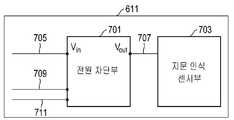
도 7은 본 발명의 일 실시 예에 따른 지문 인식 감지부의 블록 구성도이다. 도 7을 참조하면, 상기 지문 인식 감지부(611)는 지문 인식 센서부(703)와 전원 차단부(701)를 포함할 수 있다. 상기 지문 인식 센서부(703)는 상기 지문 감지부(22) 에 포함된 지문센서 및 관련 회로를 포함할 수도 있다.
7 is a block diagram of a fingerprint recognition sensing unit according to an embodiment of the present invention. Referring to FIG. 7, the fingerprint
각 구성요소를 설명하면, 상기 지문 인식 센서부(703)는 사용자에 의해 입력되는 지문을 인식하여 지문 이미지를 생성할 수 있다. 그리고 상기 전원 차단부(701)는 상기 전원부(609)와 연결된 전원 라인(705)과 상기 지문 인식 센서부(703)와 연결된 전원 라인(707)을 포함하고, 상기 제어부(601)로 신호를 출력하는 제어 라인(709) 및 상기 제어부(501)로부터 신호를 전달답는 제어 라인(711)을 포함할 수 있다. 여기서, 전원 라인들(705, 707)은 지문 인식 센서부(703)의 전원을 공급하기 위한 라인들을 말한다.When describing each component, the fingerprint
상기 전원 차단부(701)는 지문 인식 센서에 과전류가 인가되면, 지문 인식 센서에 인가되는 전원의 공급을 중단한다. 예를 들면, 상기 전원 차단부(701)는 상기 지문 인식 센서부(703)로 인가되는 전원의 전류 값을 측정할 수 있다. 예를 들면, 전원 차단부(701)는 지문 인식 센서부(703)로 인가되는 전원 라인(707)의 전류 값을 측정할 수 있다.When the overcurrent is applied to the fingerprint recognition sensor, the
그리고 전원 차단부(701)는 측정된 전류 값이 미리 지정된 기준 값 이상인지 여부를 확인할 수 있다. 여기서, 미리 지정된 기준 값은 지문 인식 센서부(703)의 파손으로 인하여 지문 인식 센서부(703)에 과전류가 인가되었는지를 확인하기 위해 결정된 값을 말한다. 예를 들면, 미리 지정된 기준 값은 100 mA가 될 수 있다.In addition, the power cut-off
미리 지정된 기준 값 이상이면, 전원 차단부(701)는 상기 전원 차단부(701)는 상기 제어부(601)로 상기 지문 인식 센서부(703)의 전원이 차단되었음을 나타내는 전원 차단 신호를 전송할 수 있다. 예를 들면, 상기 전원 차단부(701)는 상기 제어 라인(709)을 통해 상기 제어부(601)로 상기 전원 차단 신호를 전송할 수 있다.If it is equal to or greater than a predetermined reference value, the
그리고 상기 전원 차단부(701)는 상기 지문 인식 센서부(703)로 인가되는 전원을 차단할 수 있다. 예를 들면, 상기 전원 차단부(701)는 스위치를 이용하여 상기 지문 인식 센서부(703)로 인가되는 상기 전원 라인(707)을 오프시킴으로써 전원을 차단할 수 있다.
In addition, the power cut-off
상기 제어부(601)는 상기 전자 장치의 전반적인 동작을 제어하는 기능을 수행한다. 예를 들면, 상기 제어부(601)는 상기 지문 인식 감지부(611)로부터 전원 차단 신호가 수신되는지 여부를 확인한다. 예를 들면, 상기 제어부(601)는 상기 제어 라인(709)를 통해 상기 전원 차단 신호를 수신할 수 있다.The control unit 601 performs a function of controlling the overall operation of the electronic device. For example, the control unit 601 checks whether a power-off signal is received from the fingerprint
상기 전원 차단 신호가 수신되면, 상기 제어부(601)는 상기 지문 인식 감지부(611)에 인가되는 전원을 차단할 수 있다. 예를 들면, 상기 제어부(601)는 스위치를 이용하여 상기 전원 라인(705)를 오프시킴으로써 상기 지문 인식 센서부(703)의 전원을 차단할 수 있다. 다른 예로, 상기 제어부(601)는 상기 지문 인식 센서부(703)와 상기 전원 차단부(701)에 전원을 공급하는 전원 라인을 오프시킨으로써 상기 지문 인식부(611)의 전원을 차단할 수 있다.When the power off signal is received, the controller 601 may cut off power applied to the
그리고 상기 제어부(601)는 상기 지문 인식 센서부(703)의 고장을 알리는 메시지를 생성하고, 상기 생성된 메시지를 출력할 수 있다. 예를 들면, 상기 제어부(601)는 도 10과 같이, 상기 지문 인식 센서부(703)의 고장을 알리는 문자를 포함하는 팝업창을 표시할 수 있다. 다른 예로, 제어부(601)는 음향 처리부(미도시)를 통해 상기 지문 인식 센서부(703)의 고장을 알리는 메시지를 출력할 수 있다.In addition, the control unit 601 may generate a message informing of the failure of the fingerprint
그리고 제어부(601)는 지문 인식 기능의 실행이 요청되는지 여부를 확인할 수 있다. 상기 지문 인식 기능은 전자 장치의 보안을 위해 실행되면, 예를 들면, 사용자의 요청에 따라 전자 장치가 슬립 상태로부터 대기 상태로 진입할 때 요청되거나 사용자에 의해 특정 애플리케이션의 실행될 때 요청될 수 있다. 상기 특정 애플리케이션은 보안성이 높은 애플리케이션을 말하며, 예를 들면, 전자 금융 관련 애플리케이션 또는 개인 정보 관련 애플리케이션이 될 수 있다.In addition, the controller 601 may check whether or not execution of the fingerprint recognition function is requested. When the fingerprint recognition function is executed for the security of the electronic device, for example, it may be requested when the electronic device enters the sleep state from the sleep state to the standby state at the user's request or when the specific application is executed by the user. The specific application refers to an application having high security, and may be, for example, an electronic finance related application or a personal information related application.
상기 지문 인식 기능의 실행이 요청되면, 상기 제어부(601)는 상기 지문 인식 센서부(703)의 고장을 알리는 메시지를 생성하고, 상기 생성된 메시지를 출력할 수 있다. 예를 들면, 상기 제어부(601)는 도 10과 같이, 상기 지문 인식 센서부(703)의 고장을 알리는 문자를 포함하는 팝업창(1003)을 표시할 수 있다. 다른 예로, 상기 제어부(601)는 음향 처리부(미도시)를 통해 상기 지문 인식 센서부(703)의 고장을 알리는 메시지를 출력할 수 있다.
When the execution of the fingerprint recognition function is requested, the control unit 601 may generate a message informing of the failure of the fingerprint
도 8은 본 발명의 일 실시 예에 따른 전원 차단부에서 전원을 차단하는 흐름도이다.8 is a flowchart of cutting off power in a power cutoff unit according to an embodiment of the present invention.
도 8을 참조하면, 801 단계에서, 상기 전원 차단부(701)는 상기 지문 인식 센서부(703)로 인가되는 전원의 전류 값을 측정한 후, 803 단계로 진행할 수 있다. 예를 들면, 상기 전원 차단부(701)는 상기 지문 인식 센서부(703)로 인가되는 상기 전원 라인(707)의 전류 값을 측정할 수 있다.Referring to FIG. 8, in
그리고 803 단계에서, 상기 전원 차단부(701)는 측정된 전류 값이 미리 지정된 기준 값 이상인지 여부를 확인할 수 있다. 여기서, 미리 지정된 기준 값은 상기 지문 인식 센서부(703)의 파손으로 인하여 상기 지문 인식 센서부(703)에 과전류가 인가되었는지를 확인하기 위해 결정된 값을 말한다. 예를 들면, 미리 지정된 기준 값은 100 mA가 될 수 있다.Then, in
미리 지정된 기준 값 이상이면, 상기 전원 차단부(701)는 805 단계로 진행하고, 그렇지 않으면, 801 단계를 반복적으로 수행할 수 있다.If it is equal to or greater than a predetermined reference value, the power cut-off
805 단계로 진행하면, 상기 전원 차단부(701)는 상기 제어부(601)로 상기 지문 인식 센서부(703)의 전원이 차단되었음을 나타내는 전원 차단 신호를 전송한 후, 807 단계로 진행할 수 있다. 예를 들면, 상기 전원 차단부(701)는 상기 제어 라인(709)을 통해 상기 제어부(601)로 상기 전원 차단 신호를 전송할 수 있다.Proceeding to step 805, the power cut-off
그리고 807 단계에서, 상기 전원 차단부(701)는 상기 지문 인식 센서부(703)로 인가되는 전원을 차단할 수 있다. 예를 들면, 상기 전원 차단부(701)는 스위치를 이용하여 상기 지문 인식 센서부(703)로 인가되는 상기 전원 라인(707)을 오프시킴으로써 전원을 차단할 수 있다.
Then, in
도 9는 본 발명의 일 실시 예에 따른 제어부에서 지문 인식 센서부의 고장을 알리는 메시지를 출력하는 흐름도이다.9 is a flowchart for outputting a message informing a failure of the fingerprint recognition sensor unit from the control unit according to an embodiment of the present invention.
도 9를 참조하면, 901 단계에서, 상기 제어부(601)는 상기 지문 인식 감지부(611)로부터 상기 전원 차단 신호가 수신되는지 여부를 확인한다. 예를 들면, 상기 제어부(601)는 상기 제어 라인(709)을 통해 상기 지문 인식 감지부(611)의 상기 전원 차단부(701)와 연결되는 경우, 상기 제어 라인(709)를 통해 상기 전원 차단 신호를 수신할 수 있다. 여기서, 상기 전원 차단 신호는 지문 인식 센서부(703)의 전원을 차단하였음을 나타내는 신호를 말한다.Referring to FIG. 9, in
상기 전원 차단 신호가 수신되면, 상기 제어부(601)는 903 단계로 진행하고, 그렇지 않으면, 901 단계로 진행할 수 있다.When the power off signal is received, the control unit 601 proceeds to step 903, otherwise, it may proceed to step 901.
903 단계로 진행하면, 상기 제어부(601)는 상기 지문 인식 감지부(611)에 인가되는 전원을 차단한 후, 905 단계로 진행할 수 있다. 예를 들면, 상기 제어부(601)는 스위치를 이용하여 상기 지문 인식 감지부(611)에 인가되는 상기 전원 라인(705)를 오프시킴으로써 상기 지문 인식 센서부(703)의 전원을 차단할 수 있다. 다른 예로, 상기 제어부(601)는 상기 지문 인식 센서부(703)와 상기 전원 차단부(701)에 전원을 공급하는 전원 라인을 오프시킨으로써 상기 지문 인식부(611)의 전원을 차단할 수 있다.Proceeding to step 903, the control unit 601 may cut off the power applied to the fingerprint
그리고 905 단계에서, 상기 제어부(601)는 상기 지문 인식 센서부(703)의 고장을 알리는 메시지를 생성하고, 상기 생성된 메시지를 출력한 후, 907 단계로 진행할 수 있다. 예를 들면, 상기 제어부(601)는 도 10과 같이, 상기 지문 인식 센서부(703)의 고장을 알리는 문자를 포함하는 팝업창을 표시할 수 있다. 다른 예로, 상기 제어부(601)는 음향 처리부(미도시)를 통해 상기 지문 인식 센서부(703)의 고장을 알리는 메시지를 출력할 수 있다.In
그리고 907 단계에서, 상기 제어부(601)는 지문 인식 기능의 실행이 요청되는지 여부를 확인할 수 있다. 상기 지문 인식 기능은 전자 장치의 보안을 위해 실행되면, 예를 들면, 사용자의 요청에 따라 전자 장치가 슬립 상태로부터 대기 상태로 진입할 때 요청되거나 사용자에 의해 특정 애플리케이션의 실행될 때 요청될 수 있다. 상기 특정 애플리케이션은 보안성이 높은 애플리케이션을 말하며, 예를 들면, 전자 금융 관련 애플리케이션 또는 개인 정보 관련 애플리케이션이 될 수 있다.Then, in
상기 지문 인식 기능의 실행이 요청되면, 상기 제어부(601)는 909 단계로 진행하고, 그렇지 않으면, 907 단계를 반복적으로 수행할 수 있다.If the fingerprint recognition function is requested to be executed, the controller 601 proceeds to step 909, otherwise, step 907 can be repeatedly performed.
909 단계로 진행하면, 상기 제어부(601)는 상기 지문 인식 센서부(703)의 고장을 알리는 메시지를 생성하고, 상기 생성된 메시지를 출력할 수 있다. 예를 들면, 상기 제어부(601)는 도 10과 같이, 상기 지문 인식 센서부(703)의 고장을 알리는 문자를 포함하는 팝업창(1003)을 표시할 수 있다. 다른 예로, 상기 제어부(601)는 음향 처리부(미도시)를 통해 상기 지문 인식 센서부(703)의 고장을 알리는 메시지를 출력할 수 있다.
Proceeding to step 909, the control unit 601 may generate a message informing of the failure of the fingerprint
도 10은 본 발명의 일 실시 예에 따라 지문 인식 센서의 고장을 알리는 메시지가 출력되는 화면을 도시한 도면이다.FIG. 10 is a diagram illustrating a screen on which a message indicating a failure of a fingerprint recognition sensor is output according to an embodiment of the present invention.
도 10을 참조하면, 상기 전자 장치는 상기 전원 차단 신호가 수신되거나 상기 전원 차단 신호가 수신된 후에 지문 인식 기능의 실행이 요청된 경우, 상기 지문 인식 센서부(703)의 고장을 알리는 문자를 포함하는 팝업창(1003)을 표시할 수 있다.
Referring to FIG. 10, when the power-off signal is received or when the execution of the fingerprint recognition function is requested after the power-off signal is received, the electronic device includes a text indicating a failure of the fingerprint
본 발명의 지문 인식 장치 및 방법은 컴퓨터로 읽을 수 있는 기록매체에 컴퓨터가 읽을 수 있는 코드로서 구현하는 것이 가능하다. 컴퓨터가 읽을 수 있는 기록매체는 컴퓨터 시스템에 의하여 읽혀질 수 있는 데이터가 저장되는 모든 종류의 기록장치를 포함한다. 기록매체의 예로는 ROM, RAM, 광학 디스크, 자기 테이프, 플로피 디스크, 하드 디스크, 비휘발성 메모리 등이 있으며, 또한 캐리어 웨이브(예를 들어 인터넷을 통한 전송)의 형태로 구현되는 것도 포함한다. 또한 컴퓨터가 읽을 수 있는 기록매체는 네트워크로 연결된 컴퓨터 시스템에 분산되어 분산방식으로 컴퓨터가 읽을 수 있는 코드가 저장되고 실행될 수 있다.The fingerprint recognition apparatus and method of the present invention can be embodied as computer readable codes on a computer readable recording medium. The computer-readable recording medium includes all kinds of recording devices in which data readable by a computer system is stored. Examples of recording media include ROM, RAM, optical disks, magnetic tapes, floppy disks, hard disks, non-volatile memories, etc., and include those implemented in the form of carrier waves (for example, transmission via the Internet). In addition, the computer-readable recording medium can be distributed over network coupled computer systems so that the computer readable code is stored and executed in a distributed fashion.
이상에서 설명한 본 발명의 지문 인식 장치 및 방법은 전술한 실시 예 및 도면에 의해 한정되는 것은 아니고, 본 발명의 기술적 범위 내에서 여러 가지 치환, 변형 및 변경이 가능함은 본 발명이 속하는 기술분야에서 통상의 지식을 가진 자에게 있어 명백할 것이다.The fingerprint recognition apparatus and method of the present invention described above are not limited by the above-described embodiments and drawings, and various substitutions, modifications and changes are possible within the technical scope of the present invention, which is usually in the technical field to which the present invention pertains. It will be clear to those who have the knowledge of
전자 장치 : 1 지문 인식 센서모듈 : 20
회로 기판 : 21 지문 감지부 : 22
돔 스위치부 : 23 키 안착부: 24
가압부 : 23a, 24a, 가이드부 : 22a
제어부 : 601표시부 : 603
입력부 : 605메모리부 : 607
전원부 : 609지문 인식 감지부: 611Electronic device: 1 Fingerprint recognition sensor module: 20
Circuit board: 21 Fingerprint detector: 22
Dome switch: 23 Key seat: 24
Pressing part: 23a, 24a, Guide part: 22a
Control unit: 601 Display unit: 603
Input: 605 Memory: 607
Power supply: 609 Fingerprint recognition sensor: 611
Claims (19)
Translated fromKorean표시부;
제어부; 및
지문 인식 감지부를 포함하며,
상기 지문 인식 감지부는 전원 차단부, 키버튼 및 상기 키버튼의 적어도 일부분에 구비된 지문 인식 센서 모듈을 포함하며,
상기 지문 인식 센서 모듈은 회로 기판, 상기 회로 기판의 제 1 면에 구비되어 지문을 감지하는 지문 감지부 및 상기 회로 기판의 제 2 면에 구비되는 돔 스위치부를 포함하며,
상기 전원 차단부는,
상기 지문 인식 센서 모듈에 과전류가 인가된 것을 식별한 것에 응답하여, 상기 지문 인식 센서 모듈의 전원 차단을 나타내는 전원 차단 신호를 상기 제어부로 전송하도록 구성되며,
상기 제어부는,
상기 전원 차단 신호가 수신된 것에 응답하여, 상기 지문 인식 센서 모듈에 인가되는 전원을 차단하도록 상기 전원 차단부를 제어하고, 상기 지문 인식 센서 모듈의 고장에 대한 메시지 정보를 표시하도록 상기 표시부를 제어하도록 구성되는, 전자 장치.
In the electronic device,
Display unit;
Control unit; And
It includes a fingerprint recognition sensor,
The fingerprint recognition detection unit includes a power cut-off unit, a key button and a fingerprint recognition sensor module provided in at least a portion of the key button,
The fingerprint sensor module includes a circuit board, a fingerprint sensing unit provided on a first surface of the circuit board to detect fingerprints, and a dome switch unit provided on a second surface of the circuit board,
The power cut-off unit,
In response to identifying that the overcurrent is applied to the fingerprint sensor module, it is configured to transmit a power-off signal indicating the power off of the fingerprint sensor module to the control unit,
The control unit,
In response to receiving the power-off signal, it is configured to control the power-off unit to cut off the power applied to the fingerprint sensor module, and to control the display unit to display message information about the failure of the fingerprint sensor module Electronic device.
상기 돔 스위치부와 접촉되는 가압부를 구비한 키 안착부를 더 포함하는 전자 장치.
According to claim 1,
An electronic device further comprising a key seating portion having a pressing portion in contact with the dome switch portion.
상기 가압부는 가압 돌기로 이루어지고,
상기 가압 돌기는 상기 키 안착부의 상면에서 돌출됨과 아울러 상기 돔 스위치의 제 2 면과 접촉되는, 전자 장치.
According to claim 2,
The pressing portion is made of a pressing projection,
The pressing protrusion protrudes from the upper surface of the key seating portion and contacts the second surface of the dome switch.
상기 가압부는 상기 돔 스위치부의 제 2 면에 돌출됨과 아울러 상기 키 안착부의 제 1 면과 접촉되는, 전자 장치.
According to claim 2,
The pressing part protrudes from the second surface of the dome switch part and is in contact with the first surface of the key seating part.
상기 키버튼은 상기 전자 장치의 홈키 또는 사이드키 중 어느 하나인 전자 장치.
According to claim 1,
The key button is one of the home key or side key of the electronic device.
상기 지문 인식 센서 모듈은 스와이프(Swipe) 방식 또는 에어리어(Area) 방식 중 어느 하나로 이루어지는, 전자 장치.
According to claim 1,
The fingerprint recognition sensor module is made of one of a swipe (Swipe) method or an area (Area) method, an electronic device.
상기 지문 감지부의 전면에는 상기 지문 인식 센서 모듈의 파손을 방지 및 보호하는 홈키 데코부가 더 구비되고,
상기 홈키 데코부의 전면에는 상기 지문 인식 센서 모듈로 유입되는 습기를 차단하는 부재가 더 구비되는, 전자 장치.
According to claim 2,
On the front surface of the fingerprint detection unit, a home key decoration unit is further provided to prevent and protect the fingerprint recognition sensor module from being damaged,
An electronic device further comprising a member for blocking moisture flowing into the fingerprint recognition sensor module on the front surface of the home key decoration unit.
상기 지문 감지부의 제 1 면에는 도장층이 구비되는, 전자 장치.
According to claim 2,
An electronic device having a coating layer on a first surface of the fingerprint sensing unit.
상기 도장층은 설정된 두께를 갖는, 전자 장치.
The method of claim 9,
The coating layer has a set thickness, the electronic device.
상기 지문 감지부의 제 1 면은 오목홈이 형성되는, 전자 장치.
According to claim 2,
An electronic device having a concave groove on the first surface of the fingerprint sensing unit.
상기 전원 차단 신호가 수신되면, 상기 지문 인식 센서 모듈의 전원 라인을 오프시키는, 전자 장치.
The method of claim 1, wherein the control unit,
When the power off signal is received, the electronic device turns off the power line of the fingerprint sensor module.
상기 전자 장치의 전원 차단부에 의해 키버튼의 적어도 일부분에 구비된 지문 인식 센서 모듈로 인가되는 과전류를 확인하는 동작;
상기 지문 인식 센서 모듈에 과전류가 인가된 것을 식별한 것에 응답하여, 상기 전원 차단부에 의해 상기 지문 인식 센서 모듈의 전원 차단을 나타내는 전원 차단 신호를 제어부로 전송하는 동작;
상기 전자 장치의 제어부에 의해 상기 전원 차단 신호가 수신된 것에 응답하여, 상기 지문 인식 센서 모듈에 인가되는 전원을 차단하도록 상기 전원 차단부를 제어하는 동작; 및
상기 제어부에 의해 상기 지문 인식 센서 모듈의 고장에 대한 메시지 정보를 표시하도록 상기 전자 장치의 표시부를 제어하는 동작을 포함하는, 전자 장치의 동작 방법.
In the operation method of the electronic device,
Checking an overcurrent applied to the fingerprint recognition sensor module provided on at least a portion of the key button by the power cutoff unit of the electronic device;
In response to identifying that an overcurrent is applied to the fingerprint recognition sensor module, transmitting a power-off signal indicating a power-off of the fingerprint recognition sensor module to the control unit by the power-off unit;
Controlling the power cut-off unit to cut off power applied to the fingerprint recognition sensor module in response to the power-off signal received by the control unit of the electronic device; And
And controlling, by the control unit, a display unit of the electronic device to display message information regarding a failure of the fingerprint sensor module.
상기 제어부에 의해, 상기 전원 차단 신호가 수신되면, 상기 지문 인식 센서모듈의 전원 라인을 오프시키는 동작을 더 포함하는, 전자 장치의 동작 방법.
The method of claim 16,
When the power-off signal is received by the control unit, further comprising the step of turning off the power line of the fingerprint recognition sensor module, the operation method of the electronic device.
Priority Applications (5)
| Application Number | Priority Date | Filing Date | Title |
|---|---|---|---|
| KR1020130108162AKR102126816B1 (en) | 2013-09-09 | 2013-09-09 | Fingerprint recognition apparatus and method |
| CN201480049608.1ACN105518707B (en) | 2013-09-09 | 2014-09-05 | Apparatus and method for identifying fingerprints |
| PCT/KR2014/008417WO2015034325A1 (en) | 2013-09-09 | 2014-09-05 | Apparatus and method for recognizing fingerprint |
| EP14843103.4AEP3044730A4 (en) | 2013-09-09 | 2014-09-05 | Apparatus and method for recognizing fingerprint |
| US14/481,791US9524413B2 (en) | 2013-09-09 | 2014-09-09 | Apparatus and method for recognizing fingerprint |
Applications Claiming Priority (1)
| Application Number | Priority Date | Filing Date | Title |
|---|---|---|---|
| KR1020130108162AKR102126816B1 (en) | 2013-09-09 | 2013-09-09 | Fingerprint recognition apparatus and method |
Publications (2)
| Publication Number | Publication Date |
|---|---|
| KR20150029256A KR20150029256A (en) | 2015-03-18 |
| KR102126816B1true KR102126816B1 (en) | 2020-07-08 |
Family
ID=52625669
Family Applications (1)
| Application Number | Title | Priority Date | Filing Date |
|---|---|---|---|
| KR1020130108162AExpired - Fee RelatedKR102126816B1 (en) | 2013-09-09 | 2013-09-09 | Fingerprint recognition apparatus and method |
Country Status (5)
| Country | Link |
|---|---|
| US (1) | US9524413B2 (en) |
| EP (1) | EP3044730A4 (en) |
| KR (1) | KR102126816B1 (en) |
| CN (1) | CN105518707B (en) |
| WO (1) | WO2015034325A1 (en) |
Families Citing this family (37)
| Publication number | Priority date | Publication date | Assignee | Title |
|---|---|---|---|---|
| JP2014186847A (en)* | 2013-03-22 | 2014-10-02 | Fujitsu Ltd | Electronic apparatus |
| KR102126816B1 (en)* | 2013-09-09 | 2020-07-08 | 삼성전자주식회사 | Fingerprint recognition apparatus and method |
| KR102353350B1 (en)* | 2015-01-15 | 2022-01-19 | 삼성디스플레이 주식회사 | Variable display device |
| KR101862674B1 (en)* | 2015-03-31 | 2018-06-11 | 인덕대학교 산학협력단 | Emotion monitoring toilet system |
| TWI543013B (en)* | 2015-05-14 | 2016-07-21 | 廣達電腦股份有限公司 | Electronic device |
| CN104866226B (en)* | 2015-05-26 | 2018-04-27 | 努比亚技术有限公司 | A kind of terminal device and its control method |
| CN104898948A (en)* | 2015-05-26 | 2015-09-09 | 努比亚技术有限公司 | Terminal device and control method for same |
| CN106919887B (en)* | 2015-12-24 | 2020-02-07 | 小米科技有限责任公司 | Fingerprint identification chip, electronic equipment and key event reporting method |
| CN105635681A (en)* | 2015-12-30 | 2016-06-01 | 广州励丰文化科技股份有限公司 | Monitoring method and system in wearable device and multi-microphone scenes |
| CN105657348A (en)* | 2015-12-30 | 2016-06-08 | 广州励丰文化科技股份有限公司 | Automatic monitoring method and system applied in multi-microphone scene |
| EP3288245B1 (en)* | 2016-08-16 | 2019-03-06 | Guangdong Oppo Mobile Telecommunications Corp., Ltd. | Fingerprint sensor and terminal using the same |
| EP3288246A1 (en) | 2016-08-16 | 2018-02-28 | Guangdong Oppo Mobile Telecommunications Corp., Ltd | Fingerprint module and method for manufacturing the fingerprint module |
| CN108462768B (en)* | 2016-08-16 | 2019-07-19 | Oppo广东移动通信有限公司 | Fingerprint module, fingerprint module manufacturing method and mobile terminal |
| US11419231B1 (en)* | 2016-09-22 | 2022-08-16 | Apple Inc. | Forming glass covers for electronic devices |
| US11535551B2 (en) | 2016-09-23 | 2022-12-27 | Apple Inc. | Thermoformed cover glass for an electronic device |
| US11565506B2 (en) | 2016-09-23 | 2023-01-31 | Apple Inc. | Thermoformed cover glass for an electronic device |
| US10800141B2 (en) | 2016-09-23 | 2020-10-13 | Apple Inc. | Electronic device having a glass component with crack hindering internal stress regions |
| KR102685894B1 (en) | 2017-02-23 | 2024-07-19 | 삼성전자주식회사 | Electronic device for authenticating based on biometric data and operating method thereof |
| US11275920B1 (en)* | 2017-09-27 | 2022-03-15 | Apple Inc. | Elongated fingerprint sensor |
| US11066322B2 (en) | 2017-12-01 | 2021-07-20 | Apple Inc. | Selectively heat-treated glass-ceramic for an electronic device |
| CN108171165B (en)* | 2017-12-28 | 2021-10-22 | 北京小米移动软件有限公司 | Fingerprint identification method, device and computer readable storage medium |
| CN108197550A (en)* | 2017-12-28 | 2018-06-22 | 北京小米移动软件有限公司 | Fault cues method, apparatus and electronic equipment |
| US11420900B2 (en) | 2018-09-26 | 2022-08-23 | Apple Inc. | Localized control of bulk material properties |
| KR102613138B1 (en)* | 2019-02-18 | 2023-12-13 | 삼성전자주식회사 | Electronic device with waterproof structure of sensor key assembly |
| US11680010B2 (en) | 2019-07-09 | 2023-06-20 | Apple Inc. | Evaluation of transparent components for electronic devices |
| KR102335003B1 (en)* | 2019-08-20 | 2021-12-06 | 주식회사 바이오로그디바이스 | the improved SOS door lock system using biometric |
| CN115955798A (en) | 2020-03-28 | 2023-04-11 | 苹果公司 | Glass cover member for housing of electronic equipment |
| US11460892B2 (en) | 2020-03-28 | 2022-10-04 | Apple Inc. | Glass cover member for an electronic device enclosure |
| US11189248B1 (en) | 2020-05-06 | 2021-11-30 | Apple Inc. | Systems and methods for switching vision correction graphical outputs on a display of an electronic device |
| US11666273B2 (en) | 2020-05-20 | 2023-06-06 | Apple Inc. | Electronic device enclosure including a glass ceramic region |
| EP4080326B1 (en)* | 2020-09-06 | 2024-06-12 | Shenzhen Goodix Technology Co., Ltd. | Capacitive fingerprint identification apparatus, preparation method, and electronic device |
| US12093359B2 (en) | 2020-09-25 | 2024-09-17 | Apple Inc. | Electronic device having a sealed biometric input system |
| WO2022133136A1 (en) | 2020-12-17 | 2022-06-23 | Apple Inc. | Fluid forming a glass component for a portable electronic device |
| WO2022133133A1 (en) | 2020-12-17 | 2022-06-23 | Apple Inc. | Forming of glass components for portable electronic devices |
| US11945048B2 (en) | 2020-12-23 | 2024-04-02 | Apple Inc. | Laser-based cutting of transparent components for an electronic device |
| US11783629B2 (en) | 2021-03-02 | 2023-10-10 | Apple Inc. | Handheld electronic device |
| US12135855B2 (en)* | 2022-06-28 | 2024-11-05 | Apple Inc. | Electronic device having a biometric input system including a composite cover element |
Citations (1)
| Publication number | Priority date | Publication date | Assignee | Title |
|---|---|---|---|---|
| KR200456903Y1 (en)* | 2010-06-01 | 2011-11-28 | 주식회사 씨큐어에이티 | Cradle for Fingerprint Security Token |
Family Cites Families (25)
| Publication number | Priority date | Publication date | Assignee | Title |
|---|---|---|---|---|
| JPH09501074A (en)* | 1993-05-20 | 1997-02-04 | ソマネテイツクス コーポレイシヨン | Improved electro-optical sensor for spectrophotometric medical devices |
| US5912612A (en)* | 1997-10-14 | 1999-06-15 | Devolpi; Dean R. | Multi-speed multi-direction analog pointing device |
| US6661631B1 (en)* | 2000-09-09 | 2003-12-09 | Stmicroelectronics, Inc. | Automatic latchup recovery circuit for fingerprint sensor |
| US6597289B2 (en)* | 2001-07-31 | 2003-07-22 | Stmicroelectronics, Inc. | Fingerprint sensor power management detection of overcurrent |
| KR20060038274A (en)* | 2004-10-29 | 2006-05-03 | 엘지전자 주식회사 | Fingerprint sensor and fingerprint recognition device of mobile communication terminal using same |
| KR100641423B1 (en)* | 2004-12-29 | 2006-11-01 | 엘지전자 주식회사 | Fingerprint recognition system type mobile communication terminal |
| US20060181521A1 (en)* | 2005-02-14 | 2006-08-17 | Atrua Technologies, Inc. | Systems for dynamically illuminating touch sensors |
| US7364924B2 (en) | 2005-02-17 | 2008-04-29 | Sharp Laboratories Of America, Inc. | Silicon phosphor electroluminescence device with nanotip electrode |
| JP2006293760A (en)* | 2005-04-12 | 2006-10-26 | Toshiba Corp | Information processing device |
| JP2006301817A (en)* | 2005-04-18 | 2006-11-02 | Toshiba Corp | Information processing apparatus and control method |
| KR20070016329A (en)* | 2005-08-03 | 2007-02-08 | 삼성전자주식회사 | LCD module fixing structure for electrostatic discharge of portable terminal |
| KR100856203B1 (en)* | 2006-06-27 | 2008-09-03 | 삼성전자주식회사 | User input device and method using fingerprint recognition sensor |
| KR20200090943A (en) | 2007-09-24 | 2020-07-29 | 애플 인크. | Embedded authentication systems in an electronic device |
| TWI352305B (en)* | 2007-10-25 | 2011-11-11 | Htc Corp | Input panel and portable electronic device using t |
| IL196125A0 (en)* | 2008-12-23 | 2009-09-22 | Bejamin Zimchoni | A method and system for operating a keyboard with multi funcitional keys, using fingerpints recognition |
| US8791792B2 (en)* | 2010-01-15 | 2014-07-29 | Idex Asa | Electronic imager using an impedance sensor grid array mounted on or about a switch and method of making |
| KR101818111B1 (en)* | 2010-10-25 | 2018-02-21 | 엘지전자 주식회사 | Mobile terminal |
| KR101387731B1 (en)* | 2011-05-31 | 2014-04-21 | 크루셜텍 (주) | Pointing Device And Manufacturing Method Thereof |
| US8547333B2 (en)* | 2011-06-22 | 2013-10-01 | Blackberry Limited | Optical navigation device with haptic feedback |
| US9089270B2 (en) | 2011-06-29 | 2015-07-28 | Lg Electronics Inc. | Terminal and control method thereof |
| US8749970B2 (en)* | 2011-11-16 | 2014-06-10 | Precise Biometrics Ab | Security enhancing apparatus for attaching to an electronic device |
| US9030440B2 (en)* | 2012-05-18 | 2015-05-12 | Apple Inc. | Capacitive sensor packaging |
| KR101301063B1 (en)* | 2013-07-05 | 2013-08-28 | (주)드림텍 | Method of manufacturing fingerprint recognition home key using high dielectric constant material and fingerprint recognition home key structure thereof |
| KR102126816B1 (en)* | 2013-09-09 | 2020-07-08 | 삼성전자주식회사 | Fingerprint recognition apparatus and method |
| US9697409B2 (en)* | 2013-09-10 | 2017-07-04 | Apple Inc. | Biometric sensor stack structure |
- 2013
- 2013-09-09KRKR1020130108162Apatent/KR102126816B1/ennot_activeExpired - Fee Related
- 2014
- 2014-09-05WOPCT/KR2014/008417patent/WO2015034325A1/ennot_activeCeased
- 2014-09-05EPEP14843103.4Apatent/EP3044730A4/ennot_activeWithdrawn
- 2014-09-05CNCN201480049608.1Apatent/CN105518707B/ennot_activeExpired - Fee Related
- 2014-09-09USUS14/481,791patent/US9524413B2/ennot_activeExpired - Fee Related
Patent Citations (1)
| Publication number | Priority date | Publication date | Assignee | Title |
|---|---|---|---|---|
| KR200456903Y1 (en)* | 2010-06-01 | 2011-11-28 | 주식회사 씨큐어에이티 | Cradle for Fingerprint Security Token |
Also Published As
| Publication number | Publication date |
|---|---|
| US9524413B2 (en) | 2016-12-20 |
| EP3044730A1 (en) | 2016-07-20 |
| KR20150029256A (en) | 2015-03-18 |
| CN105518707A (en) | 2016-04-20 |
| EP3044730A4 (en) | 2017-09-13 |
| US20150071510A1 (en) | 2015-03-12 |
| CN105518707B (en) | 2020-06-12 |
| WO2015034325A1 (en) | 2015-03-12 |
Similar Documents
| Publication | Publication Date | Title |
|---|---|---|
| KR102126816B1 (en) | Fingerprint recognition apparatus and method | |
| US10831314B2 (en) | Method and electronic device for preventing touch button from being false triggered | |
| US9176614B2 (en) | Adapative sensing component resolution based on touch location authentication | |
| KR102187833B1 (en) | Method for executing a function and Electronic device using the same | |
| EP3383006A1 (en) | Electronic device | |
| US20180203568A1 (en) | Method for Enabling Function Module of Terminal, and Terminal Device | |
| KR20190090260A (en) | Method for providing fingerprint recognition, electronic apparatus and storage medium | |
| CN102508591A (en) | Prevention of accidental device activation | |
| CN106778183A (en) | A kind of Terminal fingerprints know method for distinguishing and mobile terminal | |
| TWI675329B (en) | Information image display method and device | |
| CN107316033A (en) | Fingerprint identification method, device and storage medium for mobile terminal, and mobile terminal | |
| JP2014514646A (en) | Terminal authentication method and terminal | |
| CN106503507A (en) | Method and mobile terminal that a kind of password shows | |
| CN106557259A (en) | A kind of operational approach and mobile terminal of mobile terminal | |
| KR102320072B1 (en) | Electronic device and method for controlling of information disclosure thereof | |
| CN109582416A (en) | Fingerprint acquisition method and device, storage medium and electronic equipment | |
| US10423249B2 (en) | Information processing method and electronic device | |
| CN107704745A (en) | A kind of biological feather recognition method and mobile terminal | |
| CN107506198A (en) | The display methods and mobile terminal of a kind of mobile terminal | |
| CN105074810A (en) | Portable electronic device, control method therefor, and program | |
| CN106802710B (en) | Electronic device and driving method | |
| CN106056011A (en) | Display method and mobile terminal | |
| CN105516983A (en) | Authentication method and authentication device | |
| US20170277930A1 (en) | Control method and device for terminal | |
| CN106778339A (en) | A kind of method for secret protection and device, mobile terminal |
Legal Events
| Date | Code | Title | Description |
|---|---|---|---|
| PA0109 | Patent application | St.27 status event code:A-0-1-A10-A12-nap-PA0109 | |
| P11-X000 | Amendment of application requested | St.27 status event code:A-2-2-P10-P11-nap-X000 | |
| P13-X000 | Application amended | St.27 status event code:A-2-2-P10-P13-nap-X000 | |
| PG1501 | Laying open of application | St.27 status event code:A-1-1-Q10-Q12-nap-PG1501 | |
| A201 | Request for examination | ||
| PA0201 | Request for examination | St.27 status event code:A-1-2-D10-D11-exm-PA0201 | |
| E902 | Notification of reason for refusal | ||
| PE0902 | Notice of grounds for rejection | St.27 status event code:A-1-2-D10-D21-exm-PE0902 | |
| E13-X000 | Pre-grant limitation requested | St.27 status event code:A-2-3-E10-E13-lim-X000 | |
| P11-X000 | Amendment of application requested | St.27 status event code:A-2-2-P10-P11-nap-X000 | |
| P13-X000 | Application amended | St.27 status event code:A-2-2-P10-P13-nap-X000 | |
| E701 | Decision to grant or registration of patent right | ||
| PE0701 | Decision of registration | St.27 status event code:A-1-2-D10-D22-exm-PE0701 | |
| PR0701 | Registration of establishment | St.27 status event code:A-2-4-F10-F11-exm-PR0701 | |
| PR1002 | Payment of registration fee | St.27 status event code:A-2-2-U10-U11-oth-PR1002 Fee payment year number:1 | |
| PG1601 | Publication of registration | St.27 status event code:A-4-4-Q10-Q13-nap-PG1601 | |
| PC1903 | Unpaid annual fee | St.27 status event code:A-4-4-U10-U13-oth-PC1903 Not in force date:20230620 Payment event data comment text:Termination Category : DEFAULT_OF_REGISTRATION_FEE | |
| PC1903 | Unpaid annual fee | St.27 status event code:N-4-6-H10-H13-oth-PC1903 Ip right cessation event data comment text:Termination Category : DEFAULT_OF_REGISTRATION_FEE Not in force date:20230620 | |
| P22-X000 | Classification modified | St.27 status event code:A-4-4-P10-P22-nap-X000 |