KR102125004B1 - Intraocular lens inserter - Google Patents
Intraocular lens inserterDownload PDFInfo
- Publication number
- KR102125004B1 KR102125004B1KR1020157000050AKR20157000050AKR102125004B1KR 102125004 B1KR102125004 B1KR 102125004B1KR 1020157000050 AKR1020157000050 AKR 1020157000050AKR 20157000050 AKR20157000050 AKR 20157000050AKR 102125004 B1KR102125004 B1KR 102125004B1
- Authority
- KR
- South Korea
- Prior art keywords
- intraocular lens
- compressed gas
- cartridge
- actuator
- inserter
- Prior art date
- Legal status (The legal status is an assumption and is not a legal conclusion. Google has not performed a legal analysis and makes no representation as to the accuracy of the status listed.)
- Active
Links
Images


Classifications
- A—HUMAN NECESSITIES
- A61—MEDICAL OR VETERINARY SCIENCE; HYGIENE
- A61F—FILTERS IMPLANTABLE INTO BLOOD VESSELS; PROSTHESES; DEVICES PROVIDING PATENCY TO, OR PREVENTING COLLAPSING OF, TUBULAR STRUCTURES OF THE BODY, e.g. STENTS; ORTHOPAEDIC, NURSING OR CONTRACEPTIVE DEVICES; FOMENTATION; TREATMENT OR PROTECTION OF EYES OR EARS; BANDAGES, DRESSINGS OR ABSORBENT PADS; FIRST-AID KITS
- A61F2/00—Filters implantable into blood vessels; Prostheses, i.e. artificial substitutes or replacements for parts of the body; Appliances for connecting them with the body; Devices providing patency to, or preventing collapsing of, tubular structures of the body, e.g. stents
- A61F2/02—Prostheses implantable into the body
- A61F2/14—Eye parts, e.g. lenses or corneal implants; Artificial eyes
- A61F2/16—Intraocular lenses
- A61F2/1662—Instruments for inserting intraocular lenses into the eye
- A61F2/167—Instruments for inserting intraocular lenses into the eye with pushable plungers
- A—HUMAN NECESSITIES
- A61—MEDICAL OR VETERINARY SCIENCE; HYGIENE
- A61F—FILTERS IMPLANTABLE INTO BLOOD VESSELS; PROSTHESES; DEVICES PROVIDING PATENCY TO, OR PREVENTING COLLAPSING OF, TUBULAR STRUCTURES OF THE BODY, e.g. STENTS; ORTHOPAEDIC, NURSING OR CONTRACEPTIVE DEVICES; FOMENTATION; TREATMENT OR PROTECTION OF EYES OR EARS; BANDAGES, DRESSINGS OR ABSORBENT PADS; FIRST-AID KITS
- A61F2/00—Filters implantable into blood vessels; Prostheses, i.e. artificial substitutes or replacements for parts of the body; Appliances for connecting them with the body; Devices providing patency to, or preventing collapsing of, tubular structures of the body, e.g. stents
- A61F2/02—Prostheses implantable into the body
- A61F2/14—Eye parts, e.g. lenses or corneal implants; Artificial eyes
- A61F2/16—Intraocular lenses
- A61F2/1662—Instruments for inserting intraocular lenses into the eye
- A61F2/1678—Instruments for inserting intraocular lenses into the eye with a separate cartridge or other lens setting part for storage of a lens, e.g. preloadable for shipping
- A—HUMAN NECESSITIES
- A61—MEDICAL OR VETERINARY SCIENCE; HYGIENE
- A61F—FILTERS IMPLANTABLE INTO BLOOD VESSELS; PROSTHESES; DEVICES PROVIDING PATENCY TO, OR PREVENTING COLLAPSING OF, TUBULAR STRUCTURES OF THE BODY, e.g. STENTS; ORTHOPAEDIC, NURSING OR CONTRACEPTIVE DEVICES; FOMENTATION; TREATMENT OR PROTECTION OF EYES OR EARS; BANDAGES, DRESSINGS OR ABSORBENT PADS; FIRST-AID KITS
- A61F9/00—Methods or devices for treatment of the eyes; Devices for putting in contact-lenses; Devices to correct squinting; Apparatus to guide the blind; Protective devices for the eyes, carried on the body or in the hand
- A61F9/007—Methods or devices for eye surgery
- A61F9/00736—Instruments for removal of intra-ocular material or intra-ocular injection, e.g. cataract instruments
- A—HUMAN NECESSITIES
- A61—MEDICAL OR VETERINARY SCIENCE; HYGIENE
- A61F—FILTERS IMPLANTABLE INTO BLOOD VESSELS; PROSTHESES; DEVICES PROVIDING PATENCY TO, OR PREVENTING COLLAPSING OF, TUBULAR STRUCTURES OF THE BODY, e.g. STENTS; ORTHOPAEDIC, NURSING OR CONTRACEPTIVE DEVICES; FOMENTATION; TREATMENT OR PROTECTION OF EYES OR EARS; BANDAGES, DRESSINGS OR ABSORBENT PADS; FIRST-AID KITS
- A61F9/00—Methods or devices for treatment of the eyes; Devices for putting in contact-lenses; Devices to correct squinting; Apparatus to guide the blind; Protective devices for the eyes, carried on the body or in the hand
- A61F9/007—Methods or devices for eye surgery
Landscapes
- Health & Medical Sciences (AREA)
- Ophthalmology & Optometry (AREA)
- Public Health (AREA)
- Life Sciences & Earth Sciences (AREA)
- Veterinary Medicine (AREA)
- Engineering & Computer Science (AREA)
- Biomedical Technology (AREA)
- Heart & Thoracic Surgery (AREA)
- Vascular Medicine (AREA)
- General Health & Medical Sciences (AREA)
- Animal Behavior & Ethology (AREA)
- Oral & Maxillofacial Surgery (AREA)
- Cardiology (AREA)
- Transplantation (AREA)
- Nuclear Medicine, Radiotherapy & Molecular Imaging (AREA)
- Surgery (AREA)
- Prostheses (AREA)
Abstract
Translated fromKorean
Description
Translated fromKorean관련 출원Related applications
본 특허출원과 함께 출원되고, 출원 데이터 서류에 외국 또는 국내의 우선권 출원이 기재된 임의의 그리고 모든 출원들은 본 명세서에서 37 CFR 1.57을 참조하여 인용된다.Any and all applications filed with this patent application and whose foreign or domestic priority applications are listed in the application data documents are incorporated herein by reference to 37 CFR 1.57.
본 특허출원은 2012년 6월 4일에 출원된 미국 가특허출원번호 61/655,255호를 기초로 우선권을 주장하고 있는데, 이 미국특허출원은 본 명세서에서 참조문헌으로 인용된다.
This patent application claims priority based on U.S. Provisional Patent Application No. 61/655,255, filed on June 4, 2012, which is incorporated herein by reference.
기술 분야Technical field
본 명세서에 기술된 발명은 동물의 눈 안에 안구내 수정체를 삽입하기 위한 장치 및 방법에 관한 것이다.
The invention described herein relates to an apparatus and method for inserting an intraocular lens into the eye of an animal.
백내장은 광의 통과를 차단하고 불투명 정도가 약간 내지는 완전히 변하며 눈의 수정체(crystalline lens) 또는 덮개(수정체 전낭) 안에서 발생되는 불투명 증상(clouding)이다. 노화-관련 백내장의 발생 초기에서, 수정체의 파워(power)가 증가되어 근시(근시안)가 되고 수정체가 점차 노랗게 되고 혼탁하게 되어 청색의 인식이 줄어들 수 있다. 백내장은 통상 서서히 진행되어 시력이 감소하고 치료하지 않은 경우 잠재적으로는 실명에 이르게 된다. 이러한 상태는 보통 양쪽 눈에 모두 영향을 끼치지만, 거의 대부분의 경우, 다른 쪽 눈보다 한쪽 눈에 먼저 영향을 끼치게 된다. 다음은 상이한 타입의 백내장 리스트이다:Cataracts are opaque symptoms (clouding) that occur in the crystalline lens or lid (optical capsule) of the eye, blocking the passage of light, the degree of opacity being slightly or completely changed. In the early stages of aging-related cataracts, the power of the lens increases, resulting in myopia (myopia), the lens gradually yellowing and turbidity, thereby reducing the perception of blue. Cataracts usually progress slowly, reducing vision and potentially leading to blindness if not treated. This condition usually affects both eyes, but in most cases, it affects one eye before the other. Here is a list of different types of cataracts:
노인성 백내장 - 이 백내장은 초기에 수정체가 불투명해지고 그 후 수정체가 팽창되며 마지막으로 수축되어, 투명도가 완전히 손상되는데, 노인들에게 발생하는 타입의 백내장이다.Senile cataract-This cataract is a type of cataract that occurs in the elderly, with the lens initially opaque, then the lens swelling and finally contracting, resulting in complete loss of transparency.
모르가니 백내장 - 이 백내장은, 수정체 전낭이 파열되고 균열이 생긴 경우, 심각한 염증을 야기할 수 있는 유백색 유체를 형성하는 액화성 백내장 피질이 형성되는 백내장으로서, 백내장이 진행되면서 발생한다. 백내장을 치료하지 않고 진행된 후에는, 수정체팽대 녹내장(phacomorphic glaucoma)이 야기될 수도 있다. 약한 수정체소대(zonules)를 수반하는 매우 진행된 백내장으로 인해, 앞 또는 뒤로 수정체탈구(dislocation)가 되기 쉽다.Morgany Cataracts-Cataracts are cataracts that form a liquefied cataract cortex that forms a milky-white fluid that can cause severe inflammation when the lens capsule is ruptured and cracked. After progressing without treatment of cataracts, phacomorphic glaucoma may also occur. Due to the very advanced cataracts with weak zonules, it is easy to dislocate the anterior or posterior lens.
외상(trauma)으로 야기된 백내장 - 이 백내장은 위에서 언급한 경우와는 달리 외상으로 인해 건강한 사람의 눈에 발생되는 타입이다. 눈에 대한 사고 상해로부터 야기된 흉부 압박상(Blunt trauma) 또는 흉부 관통상(penetrating trauma)은 수정체 불투명화를 야기할 수 있다. 망막 수술, 가령, 주변부 포도막염 유리체절제술로 인해, 수술후 백내장이 수술 뒤 6 내지 9개월 내에 발생할 것이다. 드물게는, 망막 수술 동안 수술도구에 의해 건강한 수정체에 접촉될 때 발생할 수 있는 부작용이다. 접촉 수 분 내에 수정체 불투명 증상 및 백내장이 형성된다.Cataracts caused by trauma-This cataract is a type that occurs in the eyes of healthy people due to trauma, unlike the cases mentioned above. A bleeding trauma or penetrating trauma resulting from an accidental injury to the eye can cause lens opacification. Due to retinal surgery, such as peripheral uveitis vitrectomy, cataracts after surgery will develop within 6 to 9 months after surgery. Rarely, it is a side effect that can occur when a healthy lens is contacted by surgical instruments during retinal surgery. Symptoms of lens opacity and cataracts form within minutes of contact.
선천성 백내장 - 출산 전 또는 출산 직후에 유아에게 발생하는 백내장이다.Congenital cataracts-cataracts that occur in infants before or after childbirth.
미국에서, 52세 내지 64세 사이에서는 42%, 65세 내지 74세 사이에서는 60%, 그리고, 75세 내지 85세 사이의 노인에게는 91%의 노화-관련 수정체 변화(lenticular change)가 보고되었다.In the United States, aging-related lenticular changes have been reported of 42% between 52 and 64, 60% between 65 and 74, and 91% of the elderly between 75 and 85.
세계보건기구에 따르면, 노화-관련 백내장은 세계적인 맹(world blindness)의 48%에 대해 책임이 있는데, 이는 약 1800만명의 사람에 해당된다. 지속적인 인구 증가로 인해 평균 연령이 변화하여, 백내장을 갖고 있는 환자들의 수가 증가한다. 오존층의 고갈로 인해 자외선 복사가 늘어나는 것도 백내장 질환이 추가로 증가하는 원인으로 예측된다.According to the World Health Organization, aging-related cataracts are responsible for 48% of the world's blindness, about 18 million people. The average age has changed due to continued population growth, increasing the number of patients with cataracts. The increase in UV radiation due to the depletion of the ozone layer is also predicted as a further cause of cataract disease.
다수의 국가에서, 수술 서비스는 불충분하며, 백내장은 실명의 주된 원인으로 남아 있다. 선진국 및 개발도상국 모두에게 백내장은 저시력(low vision)의 커다란 원인이다. 심지어, 수술 서비스가 충분한 나라에서도, 수술을 위한 오랜 기다림, 그리고, 수술에 대한 장애물, 가령, 비용, 정보 부족 및 환자 수송 문제점들로 인해, 백내장과 관련된 저시력은 보편적이다.In many countries, surgical services are insufficient, and cataracts remain the leading cause of blindness. Cataracts are a major cause of low vision in both developed and developing countries. Even in countries with sufficient surgical services, low vision associated with cataracts is common due to long waits for surgery and obstacles to surgery such as cost, lack of information and patient transport problems.
몇몇 원인들이 백내장 형성을 촉진시킬 수 있는데, 이 원인들에는, 가령, 자외선광에 오랜 기간 동안의 노출, 이온화방사선(ionizing radiation)에 대한 노출, 질병, 가령, 당뇨, 고혈압 및 노화, 또는 외상(아마도, 유년 시기)의 후유증이 포함되며, 이것들은 수정체 단백질의 변성 때문이다. 종종, 통상적인 원인들이 선천성 백내장의 원인이 되기도 하며, 양성 가족력(positive family history) 또한, 유년기에 백내장이 발생되기 쉽고, 전노인성 백내장이 예측되는 현상에 중요한 역할을 할 것이다. 백내장은 눈의 상해 또는 육체적 외상에 의해 발생될 수도 있다.Several causes can promote cataract formation, including long-term exposure to ultraviolet light, exposure to ionizing radiation, diseases, such as diabetes, hypertension and aging, or trauma ( Presumably, sequelae of childhood) are due to degeneration of the lens protein. Often, common causes are congenital cataracts, and positive family history is also likely to develop cataracts in childhood, and will play an important role in predicting pre-senile cataracts. Cataracts can also be caused by eye injury or physical trauma.
민항기 조종사들 중 아이슬란드항공 조종사들에 관한 연구에 따르면, 비-비행 직업을 가진 사람보다 백내장이 발생될 확률이 3배 높았다. 이는, 우주공간으로부터 오는 방사선이 지표면에서는 대기 흡수에 의해 감쇠하게 되는 반면, 높은 고도에서는 과도하게 노출되기 때문인 것으로 생각된다. 이 이론은, 지구 궤도 밖으로 비행하는 아폴로 8호 미션에 참가했던 36명의 아폴로 우주비행사들 중 33명에게서 초기 단계의 백내장이 발생되었으며, 백내장은 비행 동안 우주방사선(cosmic ray)에 노출됨으로써 야기된 것으로 밝혀진 보고서에 의해 뒷받침된다. 적어도, 39명의 이전 우주비행사들에게서도 백내장이 발생되었으며 이중 36명은 고-방사선 미션, 가령, 아폴로 미션에 참가했었다.A study of Icelandic pilots among civilian pilots found that cataracts were three times more likely than people with non-flight jobs. This is thought to be because radiation from outer space is attenuated by atmospheric absorption at the surface, while excessively exposed at high altitude. The theory is that early cataracts occurred in 33 of the 36 Apollo astronauts who participated in the mission of the Apollo 8 flying out of orbit, and the cataracts were caused by exposure to cosmic rays during flight. It is supported by a report that was revealed. Cataracts have also occurred in at least 39 former astronauts, of whom 36 have participated in high-radiation missions, such as the Apollo mission.
또한, 백내장은 적외선에 노출되는 사람들, 가령, 수정체비늘증후군(exfoliation syndrome)으로 고통받는 유리직공(glassblower)들에게도 일반적으로 보편화되어 있다. 또한, 전자기파(microwave radiation)에 노출되어도 백내장이 발생될 수 있다. 특히, 어린이들에게 있어서, 아토피 또는 알러지성 질환들도 백내장의 진행을 앞당기는 것으로 알려져 있다. 또한, 백내장은 요오드 결핍증(iodine deficiency)에 의해서도 발생될 수 있다. 백내장은 부분적 또는 전체적일 수도 있고, 정체되어 있거나 혹은 진행형일 수도 있으며, 또는 심하거나 혹은 약할 수도 있다. 몇몇 약물, 가령, 코르티코스테로이드(corticosteroid) 및 항정신병 약물, 가령, 쿠에타핀(quetiapine)(쎄로켈(Seroquel), 케티피노르(Ketipinor), 또는 쿠에핀(Quepin) 명칭으로 판매됨)이 백내장 발생을 유발할 수 있다.In addition, cataracts are also common in people who are exposed to infrared radiation, for example, glassblowers suffering from exfoliation syndrome. In addition, cataracts may occur even when exposed to microwave radiation. In particular, in children, atopic or allergic diseases are also known to accelerate the progression of cataracts. In addition, cataracts can also be caused by iodine deficiency. Cataracts can be partial or total, stagnant or progressive, or severe or weak. Several drugs, such as corticosteroid and antipsychotic drugs, such as quetiapine (sold under the name Seroquel, Ketipinor, or Quepin), are cataracts May cause development.
백내장을 제거하기 위한 수술은 백내장 발생 중 임의의 단계에서도 시술될 수 있다. 백내장을 제거하기 전에 백내장이 완전히 진행될 때까지 기다릴 어떠한 이유도 없다. 하지만, 모든 수술은 어느 정도의 위험성을 내포하고 있기 때문에, 백내장을 제거하기 전에 어느 정도의 시력 변화가 있을 때까지 기다릴 필요가 있을 것이다.Surgery to remove cataracts can be performed at any stage during cataract development. There is no reason to wait for the cataract to progress completely before removing the cataract. However, because all surgeries pose a certain degree of risk, you may need to wait for some degree of vision change before removing the cataract.
가장 효과적이면서 보편적인 치료법은 불투명한 수정체 전낭 내에 절개부위를 형성하여(피막절개술) 외과수술로 백내장을 제거하는 것이다. 백내장을 제거하기 위해 2가지 타입의 눈 수술: 수정체 낭외적출술(extra-capsular cataract extraction; ECCE) 및 수정체 낭내적출술(intracapsular cataract extraction; ICCE)이 사용될 수 있다. 수정체 낭외적출술은 수정체를 제거하지만 수정체 전낭의 대부분은 손대지 않은 채로 그냥 남겨두는 것으로 구성된다. 적출 전에 수정체를 분리시키기 위하여 종종 초음파(수정체 유화술)가 사용된다. 수정체 낭내적출술은 수정체와 수정체 전낭을 제거하는 것을 포함하지만, 최근에는 거의 시술되지 않는다. 수정체 낭외적출술 또는 낭내적출술에서, 백내장이 있는 수정체가 제거되고 안구내 플라스틱 수정체(안구내 수정체 임플란트)로 교체되며, 이 안구내 플라스틱 수정체는 눈 안에 영구히 위치된다. 안구내 수정체는 카트리지 내에 위치되고 작은 수술 절개부위를 통해 삽입된다. 삽입기는 안구내 수정체를 접어서 작은 바늘을 통해 밀어 넣는다. 바늘의 단부는 전낭 백(capsular bag) 내에 위치된다. 접혀진 안구내 수정체가 바늘의 단부로부터 배출될 때, 의사가 수정체를 최종 위치 안에 배열되도록 조작함에 따라 안구내 수정체는 서서히 펼쳐진다(unfold). 백내장 수술은 일반적으로 국부마취제를 사용하여 시술되며, 환자는 당일에 퇴원할 수 있다. 21세기 초반까지는 안구내 수정체가 항상 단안시(monofocal)였으며, 그 이후로는 안구내 기술(intraocular technology)이 향상되어, 다중초점렌즈를 이식함으로써 환자가 안경에 덜 좌우되는 시각 환경을 형성할 수 있게 되었다. 이러한 다중초점렌즈는 기계적으로 유연하게 작동되며 자연적인 수정체를 조절하도록 사용되는 눈 근육을 사용하여 조절될 수 있다.The most effective and universal treatment is surgical removal of the cataract by forming an incision in the opaque capsular bag (capsulotomy). Two types of eye surgery can be used to remove cataracts: extra-capsular cataract extraction (ECCE) and intracapsular cataract extraction (ICCE). Extracapsular removal of the lens consists of removing the lens, but most of the lens capsule is left untouched. Ultrasound (phacoemulsification) is often used to separate the lens before extraction. Intracapsulotomy involves the removal of the capsular and capsular anterior capsule, but is rarely performed in recent years. In capsulotomy or capsulotomy, a cataract lens is removed and replaced with an intraocular plastic lens (intraocular lens implant), which is permanently located in the eye. The intraocular lens is placed in the cartridge and inserted through a small surgical incision. The inserter folds the intraocular lens and pushes it through a small needle. The end of the needle is located in a capsular bag. When the folded intraocular lens is ejected from the end of the needle, the intraocular lens slowly unfolds as the physician manipulates the lens to be arranged in the final position. Cataract surgery is usually performed using a local anesthetic, and the patient can be discharged on the same day. Until the beginning of the 21st century, intraocular lens was always monofocal, and since then intraocular technology has been improved, by implanting multifocal lenses, patients can create a less dependent visual environment for glasses. It became. These multifocal lenses operate mechanically flexibly and can be adjusted using the eye muscles used to control the natural lens.
백내장 수술에 후에 합병증, 가령, 내안구염(endophthalmitis), 후발백내장(posterior capsular opacification) 및 망막박리(retinal detachment)도 발생할 수 있다.Complications after cataract surgery can also occur, such as endophthalmitis, posterior capsular opacification, and retinal detachment.
레이저 시술(laser surgery)은 광이 눈을 통해 직접 망막에 도달할 수 있기에 충분하게 수정체 전낭의 작은 원 형태의 영역을 절단하는 것을 포함한다. 언제나처럼, 어느 정도의 위험성이 존재하지만 심각한 부작용은 매우 드물게 발생한다. 2012년까지, 백내장 수술을 위해 극초단파(펨토초) 레이저 사용에 대한 연구가 수행되었다. 현재는 백내장 수정체를 추출하기 위해서 고주파 초음파가 가장 일반적인 수단이다.Laser surgery involves cutting a small circular area of the capsular anterior capsule enough to allow light to reach the retina directly through the eye. As always, there are some risks, but serious side effects occur very rarely. Until 2012, research on the use of microwave (femtosecond) lasers for cataract surgery has been conducted. At present, high-frequency ultrasound is the most common method for extracting a cataract lens.
백내장 수술은 감염, 특히, 급속하게 빠른 치명적인 감염으로 인해 수일 내에 실명에 이를 수도 있는 내안구염의 위험을 방지하기 위하여 멸균 상태 하에서 수술실에서 시술된다. 환자의 눈을 소독제로 세척하고, 그 뒤, 오직 눈만 노출한 채로 환자를 무균 천으로 완전히 격리시킨다. 임의의 인원 또는 기기를 적절히 소독하고 덮거나 살균처리하도록 환자 주변에 살균 환경이 형성된 뒤, 표준적인 무균 수술이 뒤따른다.Cataract surgery is performed in an operating room under sterile conditions to prevent the risk of infection of the eye, which may lead to blindness within a few days due to infection, especially rapidly and rapidly fatal infections. The patient's eyes are cleaned with a disinfectant, and then the patient is completely isolated with a sterile cloth with only the eyes exposed. A sterile environment is formed around the patient to properly disinfect, cover, or disinfect any personnel or devices, followed by standard aseptic surgery.
도 1과 2를 보면, 이러한 종래 기술 타입의 백내장 수술은 환자의 각막 및 홍채를 통해 눈의 내부를 볼 수 있도록 수술용 현미경을 사용하는 것을 포함한다. 의사는 보통 연곽(limbus)에 가까운 환자의 각막 내에 2개의 절개부위(10, 12)를 형성하여, 수술 기기가 눈의 내부 세그먼트에 접근될 수 있으며 백내장 수정체가 제거되고 난 뒤에 안구내 수정체를 이식할 수 있게 된다. 예를 들어, 안구내 수정체 삽입기(14)가 절개부위(10)를 통해 삽입될 수 있으며 배치 장치(16)가 절개부위(12)를 통해 삽입될 수 있다.1 and 2, this prior art type of cataract surgery involves using a surgical microscope to see the inside of the eye through the patient's cornea and iris. Doctors usually form two incisions (10, 12) in the cornea of a patient close to the limbus, so that surgical instruments can access the inner segment of the eye and implant the intraocular lens after the cataract lens is removed. I can do it. For example, the
수술은 통상, 수정체전낭절개술(capsulorhexis)로 지칭되는, 내측면 위에 있는 전낭 백(capsular bag)의 중앙에 완전한 원형 절개선을 형성하여 전낭의 원형 절개부를 제거하는 것을 포함한다. 그 뒤, 백내장 수정체는 수정체유화기(phacoemulsifer), 초음파 융합(ultrasonic infusing) 및 백내장을 절단하고 그 단편들을 흡인하여 백내장을 제거하는 흡인 기기(aspirating instrument)를 사용하여 제거된다.Surgery usually involves removing a circular incision of the anterior capsule by forming a complete circular incision in the center of the capsular bag over the medial surface, called capsulorhexis. The cataract lens is then removed using an aspirating instrument that cuts the cataract by cutting the phagoemulsifer, ultrasonic infusing and cataract and aspirating the fragments.
그 뒤, 융합/흡인 기기를 이용하여 전낭 백의 내측 표면에 결부된 오래 끄는 피질 재료(lingering cortical material)가 흡입된다. 그 다음에, 수정체 삽입기(14)를 사용하여 안구내 수정체(18)가 삽입되고 배치 장치(16) 또는 그 외의 다른 장치들을 사용하여 전낭 백 내에 위치된다.Thereafter, the lingering cortical material attached to the inner surface of the anterior bag is inhaled using a fusion/suction device. The
수정체 삽입기(14)는 평평한 안구내 수정체(18)를 작고 투명한 각막 절개부위(10)를 통해 전낭 개구(capsular opening) 내에 삽입하여(수정체전낭절개술) 전낭 백 내의 최종 위치에 전달된다. 삽입기(14)는 카트리지를 통해 평평한 수정체(18)를 밀어 넣어 수정체가 접히고 작은 절개부위(10 내에 위치된 카트리지의 관형 부분을 통과하게 된다. 수정체(18)가 카트리지(14)의 관형 단부(tubular end)로부터 나올 때, 수정체는 서서히 펼쳐지고 원래의 평평한 형태로 복원된다.The
최근에는 펨토초 레이저 기기가 발전하여, 삽입 절개부위를 형성하고 수정체전낭절개술 뿐만 아니라 백내장을 사전-절개하는 과정이 자동화되어 백내장 수술이 보다 정밀하고, 더 안전하며 의사가 시술하기에 더 쉬워졌다.In recent years, femtosecond laser devices have been developed to automate the process of forming an incision site and pre-cutting a cataract as well as a capsulotomy, making cataract surgery more precise, safer and easier for doctors to perform.
현재의 대부분의 수정체 삽입기는 수동-작동의 재사용가능한 기기인데, 수정체를 밀어 넣는 2개의 수단 즉 리드 스크루(lead screw) 또는 플런저 중 하나이다. 리드 스크루 접근술은 수정체를 인정하고 부드럽게 전달하기는 하지만, 속도가 매우 느리고 의사 또는 보조의사가 의사가 기기의 끝단에 위치할 때 리드 스크루를 수동으로 돌려야 한다.Most current lens inserters are hand-operated, reusable devices, one of two means of pushing the lens, a lead screw or plunger. The lead screw approach recognizes the lens and delivers it smoothly, but it is very slow and requires the doctor or assistant to manually rotate the lead screw when the doctor is at the tip of the device.
플런저 접근술은, 주사기로부터 약물을 주사하는 것과 같이 의사가 자신의 엄지손가락으로 수정체를 전방을 밀어 넣기 때문에, 보조가 필요 없다. 또한, 의사는 덜 중요한 부분은 상대적으로 더 빨리 이동시키고 보다 민감한 세그먼트는 서서히 이동시킴으로써 전달 속도를 보다 용이하게 조절할 수 있다. 플런저 접근술의 한 단점은 수정체가 걸렸을 때에는, 그 장애(hang-up)를 해결하기 위해, 의사에 의해 보다 강하게 밀어 넣어, 수정체가 배출될 때 지나치게 더 많이 나가서(over-shoot) 환자에게 손상을 입힐 수도 있다는 것이다.The plunger approach requires no assistance, as the doctor pushes the lens forward with his thumb, such as by injecting drugs from a syringe. In addition, the physician can more easily adjust the delivery rate by moving less important parts relatively faster and slowly moving more sensitive segments. One drawback of the plunger approach is that when the lens is caught, it is pushed more strongly by the doctor to fix the hang-up, and over-shoot when the lens is ejected, causing damage to the patient. It can be applied.
재사용가능한 기기는 재-처리(세척 및 살균) 과정을 필요로 하며 기기에 대한 인력비용이 늘어나고 독성 전방 증후군(Toxic Anterior Segment Syndrome; TASS)의 위험이 증가한다(http://www. cdc.gov/ mmwr/preview/ mmwrhtml/ mm5625 a2.htm).Reusable devices require re-treatment (cleaning and sterilization), increased manpower costs for the device, and increased risk of Toxic Anterior Segment Syndrome (TASS) (http://www.cdc.gov /mmwr/preview/mmwrhtml/mm5625 a2.htm).
최근에는, 더 작은 각막 절개부위를 사용하여 이러한 수정체 교체 수술을 시술하기 위한 노력이 행해지고 있다. 예를 들어, 개략적인 예시된 도 3에 도시된 것과 같이, 보통, 안구내 수정체(18) 삽입 수술 동안, 안구내 수정체 삽입기(14)의 원위 단부는 절개부위(10)를 통해 완전히 삽입된다. Recently, efforts have been made to perform such a lens replacement operation using a smaller corneal incision. For example, as shown in FIG. 3 schematically illustrated, usually during an
하지만, 도 4를 보면, 최근의 의사들은 "감김-보조(wound-assist)" 기술을 적용하는데, 여기서 안구내 수정체 삽입기(14)의 끝단(20)의 오직 작은 부분만이 절개부위(10) 내에 삽입되며, 절개부위(10)는 이전의 절개부위, 가령, 도 3에 예시된 수술 동안의 절개부위보다 더 작다. 이에 따라, 접혀진 상태에 있는 안구내 수정체(18)는 절개부위(10)의 내측 표면을 통해 밀어 넣어져서 내측 표면을 따라 슬라이딩 이동된다. 이에 따라, 절개부위(10)는 더 작게 되고 자체적으로(절개부위(10)) 감겨져서 수정체(18)가 눈 안에 삽입되기 위한 내강(lumen)이 된다.However, referring to FIG. 4, recent doctors apply a “wound-assist” technique, where only a small portion of the
이러한 수술 동안, 의사는 안구내 삽입기(14)의 끝단의 원위 단부(20)를 사용하여 절개부위(10)가 개방된 채로 고정되도록 할 수 있다. 예를 들어, 의사는 절개부위(10)가 개방된 채로 고정시켜 수정체(18)가 내부를 통해 밀어 넣어질 수 있도록 하기 위하여 화살표(22) 방향으로 가로 힘(lateral force)을 제공할 수 있다.
During this surgery, the surgeon may use the
본 명세서에 기술된 발명 중 하나 이상의 형태는 의사가 작동시켜 의사가 한 손으로 삽입기 장치로부터 수정체를 배출시키며 의사가 제공해야 하는 수동 힘이 줄어들 수 있게 하는 안구내 수정체 삽입기 디자인이다. 예를 들어, 몇몇의 알려진 종래 장치, 가령, 플런저 장치에서, 삽입기 장치의 단부를 통해 수정체를 밀어 넣기 위하여 의사는 플런저의 근위 단부에 대해 상당한 수동 힘을 사용해야 한다. 이는 의사가 삽입 동안 장치를 원하는 방향 및 위치에 고정시키는 것을 어렵게 만든다. 이러한 문제점은 최근에 적용되는 수술, 가령, 도 4에 관해 위에서 기술된 수술에서는 보다 심각하다. 따라서, 보조된 배출 힘(discharge force)을 제공하는 안구내 수정체 삽입 장치는 의사가 원하는 대로 수술할 수 있도록 도와줄 수 있다.One or more aspects of the invention described herein are intraocular intraocular lens insert designs that allow a physician to actuate the lens from the inserter device with one hand and reduce the manual force the physician must provide. For example, in some known prior art devices, such as plunger devices, the surgeon must use considerable manual force against the proximal end of the plunger to push the lens through the end of the inserter device. This makes it difficult for the physician to secure the device in the desired orientation and position during insertion. This problem is more serious in recently applied surgery, such as those described above with respect to FIG. 4. Thus, an intraocular lens insertion device that provides an assisted discharge force can help the surgeon to operate as desired.
본 명세서에 기술된 발명 중 하나 이상의 또 다른 형태는, 테더(tether)에 의해 연결되지 않은, 가령, 예를 들어, 개별 콘솔(console)에 연결되지 않는, 배출 힘을 제공하기 위한 에너지를 저장하기 위해 일체형으로 구성된 메커니즘을 가진 삽입 장치를 사용함으로써 이러한 장치들에 대한 상당한 비용이 줄어들 수 있다는 점이다. 예를 들어, 몇몇 알려진 타입의 수술 장치는 전력을 전기 모터에 제공하거나 수술 장치의 핸드피스 내에 있는 압축 공기 모터에 압축 공기를 제공하는 단독 콘솔에 의해 작동되는 공압 시스템 또는 전기 모터를 포함한다. 이러한 시스템들로 인해 의사는 상기 특별한 수술 도구로 사용하기 위한 콘솔 장치를 구입하거나 임대해야 한다.Another form of one or more of the inventions described herein is to store energy to provide discharge force that is not connected by a tether, such as, for example, an individual console. The significant cost for these devices can be reduced by using an insertion device with an integrally integrated mechanism. For example, some known types of surgical devices include electric motors or pneumatic systems operated by a single console that provides electrical power to the electric motor or compressed air to a compressed air motor within the handpiece of the surgical device. These systems require the physician to purchase or rent a console device for use as the special surgical tool.
따라서, 배출 힘을 제공하기 위하여 저장 에너지를 사용하는 안구내 수정체 삽입기가 제공되는데, 상기 안구내 수정체 삽입기는 휴대성이 더 강화되어 의사가 개별적인 단독 콘솔을 구입하거나 임대할 필요가 없어진다.Thus, an intraocular lens inserter that uses stored energy to provide discharge force is provided, which further enhances portability, eliminating the need for a physician to purchase or rent an individual single console.
본 명세서에 기술된 발명 중 하나 이상의 또 다른 형태는, 출력 힘과 같이 작동될 수 있는 에너지를 저장하기 위하여 압축성 에너지 저장 장치, 가령, 스프링, 또는 압축 공기를 구현하여, 편리하고 휴대용 수단을 제공할 수 있게 하는 것이다. 하지만, 이러한 에너지 저장 장치는 예컨대 일정한 속도 출력을 제공하기 위해 조절하기가 상당히 어렵다. 따라서, 본 명세서에 기술된 발명의 하나 이상의 형태는, 실질적으로 비압축성 유체, 가령, 액체로 작동되는 작동 회로(actuating circuit)를 제공하여, 심지어 압축성 저장 장치, 가령, 스프링 또는 압축 공기에 의해 에너지가 공급되는 경우에도, 하위 구성요소들의 속도에 걸쳐 보다 정밀하게 조절할 수 있는 메커니즘 사용 방법을 수용하는 것이다.Another aspect of one or more of the inventions described herein is to implement a compressible energy storage device, such as a spring, or compressed air, to provide energy that can be actuated, such as output force, to provide a convenient and portable means. To make it possible. However, such energy storage devices are quite difficult to adjust, for example, to provide a constant speed output. Accordingly, one or more aspects of the invention described herein provide a substantially incompressible fluid, such as an actuating circuit that is actuated by a liquid, such that energy is even generated by a compressible storage device, such as a spring or compressed air. Even when supplied, it accommodates a method of using a mechanism that can be more precisely adjusted over the speed of the sub-components.
본 명세서에 기술된 발명의 하나 이상의 또 다른 형태는, 일체형 에너지 저장 장치 및 움직임 조절 액츄에이터를 포함하는 휴대용 안구내 수정체 삽입기를 제공하여, 이에 따라 상기 장치가 단일의 사용 장치 및 따라서 일회용 장치로 구성될 수 있기에 충분히 간단하며, 재살균 비용 및 상호 오염(cross-contamination)에 대한 가능성이 방지되도록 구현하는 것이다. 따라서, 예를 들어, 안구내 수정체 삽입기 장치는 압축성 에너지 저장 장치 및 하위 구성요소, 가령, 수정체 삽입 로드의 움직임 및 에너지 저장 장치에 의해 저장된 에너지 배출을 조절하기 위해 실질적으로 비압축성 유체로 작동되도록 구성된 액츄에이터를 포함할 수 있다.One or more further aspects of the invention described herein provide a portable intraocular lens insert comprising an integral energy storage device and a motion control actuator, such that the device will consist of a single use device and thus a disposable device. It is simple enough to be implemented, and is implemented so that the cost of re-sterilization and the possibility of cross-contamination are prevented. Thus, for example, the intraocular lens inserter device is configured to operate with a substantially incompressible fluid to control the movement of the compressive energy storage device and subcomponents, such as the movement of the lens insertion rod and the energy release stored by the energy storage device It may include an actuator.
상기 요약 내용은 단순한 형태의 개념을 도입하기 위해 제공되며, 밑에서 본 발명의 상세한 설명에서 추가로 기술된다. 이 요약 내용은 청구되고 있는 주제의 핵심 특징 및 실질적인 특징들을 기술하기 위한 것도 아니고, 본 발명에서 청구되고 있는 주제의 범위를 결정하는 데 보조하도록 사용되기 위한 것이다.
The above summary is provided to introduce a simple form of concept, and is further described below in the detailed description of the invention. This summary is not intended to describe key features and substantive features of the claimed subject matter, but is intended to be used to assist in determining the scope of the claimed subject matter in the present invention.
본 발명은 첨부된 도면들을 참조하여 본 발명의 상세한 설명 및 청구범위로부터 보다 완전하게 이해할 수 있는데, 도면들에서 전반적으로 유사한 도면부호는 유사한 요소들을 가리킨다.
도 1은 각막 내에 절개부위를 통해 안구내 수정체 삽입기가 삽입되고 제2 절개부위를 통해 배치 장치가 삽입된 인체 눈을 확대하여 도시한 단면도로서, 교체되는 안구내 수정체가 안구내 수정체 삽입기로부터 부분적으로 배출되어 도시된다.
도 2는 도 1에 예시된 수술의 전방 평면도이다.
도 3은 도 1에 도시된 장치의 한 부분의 개략적인 다이어그램으로서, 안구내 수정체 삽입기의 원위 끝단이 절개부위를 통해 완전히 삽입되어 교체용 수정체를 배출한다.
도 4는 도 3에 예시된 수술과 상이한 수술을 개략적으로 예시한 도면으로서, 안구내 수정체 삽입기의 원위 끝단이 절개부위 내에 오직 부분적으로만 삽입되어 있다.
도 5는 안구내 수정체 삽입기의 한 실시예를 개략적으로 예시한 도면이다.
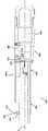
도 6은 안구내 수정체 삽입기의 추가적인 실시예의 투시도이다.
도 7은 도 6의 안구내 수정체 삽입기의 측면 입면도이자 횡단면도이다.
도 8은 도 7의 안구내 수정체 삽입기의 하우징 부재의 한 부분의 측면 입면도이자 횡단면도이다.
도 9는 도 6의 수정체 삽입기의 에너지 저장 부분의 확대 단면도이자 부분적 분해도이다.
도 10은 에너지 저장 장치에 나사고정된 단부 캡 내에 위치되며 천공 장치에 의해 천공된 에너지 저장 장치를 보여주는 도 6의 수정체 삽입기의 횡단면도이다.
도 11은 팽창 가스가 에너지 저장 장치로부터 배출되고 난 후 피스톤의 움직임을 보여주는 도 6의 삽입기의 횡단면도이다.
도 12는 도 6의 삽입기의 액츄에이터 부분을 확대하여 도시한 단면도이다.
도 13은 도 6의 삽입기의 수정체 카트리지 홀더 부분의 분해도이다.
도 14는 도 13에 도시된 삽입기의 확대 투시 분해도이다.
도 15는 수정체 카트리지 홀더 부분으로부터 제거된 수정체 카트리지의 확대 측면 입면도이다.
도 16은 수정체 카트리지가 수정체 카트리지 홀더 부분 내에 삽입된 도 15의 삽입기이다.
도 17은 수정체 카트리지가 플런저와 결합되기 전의 도 16의 삽입기의 부분적인 횡단면도이다.
도 18은 플런저를 수정체 카트리지와 결합시키기 위해 수정체 홀더 부분이 축방향으로 이동되고 난 후 도시된 삽입기의 횡단면도이다.
도 19는 에너지 저장 장치가 스프링 형태로 형성된 도 6의 삽입기의 추가적인 실시예를 예시한 도면이다.The present invention may be more fully understood from the detailed description and claims of the present invention with reference to the accompanying drawings, in which like reference numerals throughout the drawings refer to like elements.
1 is an enlarged cross-sectional view of a human eye in which an intraocular lens inserter is inserted through an incision in the cornea and a placement device is inserted through a second incision, wherein the intraocular lens to be replaced is partially from the intraocular lens inserter It is shown to be discharged.
2 is an anterior plan view of the surgery illustrated in FIG. 1.
FIG. 3 is a schematic diagram of a portion of the device shown in FIG. 1, in which the distal end of the intraocular lens inserter is fully inserted through the incision to eject the replacement lens.
4 is a view schematically illustrating a surgery different from the surgery illustrated in FIG. 3, in which the distal end of the intraocular lens inserter is only partially inserted into the incision.
5 is a view schematically illustrating an embodiment of an intraocular lens inserter.
6 is a perspective view of an additional embodiment of an intraocular lens inserter.
7 is a side elevational view and a cross-sectional view of the intraocular lens inserter of FIG. 6.
8 is a side elevational and cross-sectional view of a portion of the housing member of the intraocular lens insert of FIG. 7.
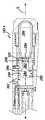
9 is an enlarged cross-sectional view and a partially exploded view of the energy storage portion of the lens insert of FIG. 6.
10 is a cross-sectional view of the lens insert of FIG. 6 showing the energy storage device perforated by the perforation device and positioned within the end cap screwed to the energy storage device.
11 is a cross-sectional view of the inserter of FIG. 6 showing the movement of the piston after the expanding gas is discharged from the energy storage device.
12 is an enlarged cross-sectional view of an actuator portion of the inserter of FIG. 6.
13 is an exploded view of the lens cartridge holder portion of the inserter of FIG. 6;
14 is an enlarged perspective exploded view of the inserter shown in FIG. 13.
15 is an enlarged side elevational view of the lens cartridge removed from the lens cartridge holder portion.
FIG. 16 is the inserter of FIG. 15 with the lens cartridge inserted into the lens cartridge holder portion.
17 is a partial cross-sectional view of the insert of FIG. 16 before the lens cartridge is engaged with the plunger.
18 is a cross-sectional view of the inserter shown after the lens holder portion has been moved axially to engage the plunger with the lens cartridge.
19 is a view illustrating an additional embodiment of the inserter of FIG. 6 in which the energy storage device is formed in the form of a spring.
다음의 상세한 설명은 단지 예시적인 목적으로 제공되는 것이지 본 발명의 실시예들의 주제 및 이러한 실시예들의 용도를 제한하기 위한 것이 아니다. 본 명세서에서 사용되는 것과 같이, 용어 "대표적인"은 "한 예, 경우, 또는 예시로서 사용되는"을 의미한다. 대표적인 예로서 본 명세서에 기술된 임의의 실시예는 반드시 그 외의 다른 실시예들에 비해 바람직하거나 유리한 것으로 간주될 필요는 없다. 게다가, 본 발명에서 앞서 기술된 기술분야, 배경기술, 발명의 내용, 또는 밑에 기술되는 발명의 상세한 설명에 기재된 임의의 명시적이거나 함축적인 이론에만 한정하려는 것도 아니다.The following detailed description is provided for illustrative purposes only and is not intended to limit the subject matter of the embodiments of the present invention and their use. As used herein, the term “representative” means “used as an example, case, or illustration”. As a representative example, any embodiment described herein is not necessarily considered to be advantageous or advantageous over other embodiments. Moreover, the present invention is not intended to be limited only to any explicit or implied theory described in the foregoing technical field, background, content of the invention, or detailed description of the invention described below.
특정 용어들이 하기 본 발명의 상세한 설명에서 참조용어로만 사용될 수 있으며, 이 또한 제한하려는 것이 아니다. 예를 들어, 용어, 가령, "상부", "하부", "위", 및 "아래"는 참조하고 있는 도면들에서 방향을 가리킨다. "근위", "원위", "전방", "뒷면", "후방", 및 "측면"과 같은 용어들은 문헌 및 이러한 논의 하에서 구성요소를 기술하는 도면에서 참조 용도로 명확한 기준의 구성요소이지만 임의의 프레임 내에 있는 구성요소 부분들의 배열방향 및/또는 위치를 기술한다. 이러한 용어는 위에서 특별히 언급한 용어, 및 그 파생형, 및 이와 유사한 용어들을 포함할 수도 있다. 이와 유사하게, 용어 "제1", "제2", 및 구성을 지칭하는 그 외의 다른 이러한 숫자 용어들은 문맥에서 명확하게 언급되지 않는 한 순서 또는 차례를 의미하지 않는다.Certain terms may be used only as reference terms in the following detailed description of the invention, but are also not intended to be limiting. For example, terms such as "top", "bottom", "top", and "bottom" indicate directions in the figures to which they refer. Terms such as "proximal", "distal", "front", "back", "rear", and "side" are components of a clear standard for reference purposes in the literature and drawings describing components under these discussions, but are arbitrary It describes the arrangement direction and/or position of component parts in the frame of. These terms may include the terms specifically mentioned above, and derivatives thereof, and similar terms. Similarly, the terms “first”, “second”, and other such numeric terms referring to construction do not imply order or order unless explicitly stated in the context.
본 명세서에 기술된 발명은 백내장을 치료하기 위한 안구내 수정체 삽입기에 관해 설명한다. 하지만, 본 명세서에 기술된 발명은 장치들을 예를 들어, 동물, 가령, 사람의 조직 내에 또는 조직을 넘어 배출하도록 요구되는 수술 장치들 뿐만 아니라 그 외의 다른 문맥에서 사용될 수 있다.The invention described herein describes an intraocular lens inserter for the treatment of cataracts. However, the invention described herein can be used in other contexts, as well as surgical devices required to discharge devices into or beyond tissues of an animal, such as a human, for example.
도 5를 보면, 안구내 수정체 삽입기(100)가 에너지 저장 장치(102), 액츄에이터 장치(104), 및 수정체 배출 부분(106)을 포함할 수 있다. 에너지 저장 부분(102)은 임의의 타입의 에너지 저장 장치 형태로 구성될 수 있다. 몇몇 실시예들에서, 에너지 저장 부분(102)은 압축성 유체를 저장하기 위한 장치, 기계식 스프링, 또는 그 외의 다른 타입의 압축성 타입의 에너지 저장 장치 형태로 구성된다. 또한, 그 밖의 타입의 에너지 저장 장치도 사용될 수 있다.Referring to FIG. 5, the
몇몇 실시예들에서, 에너지 저장 부분(102)은 내부에 저장된 에너지로부터 기계적 에너지를 배출하도록 구성될 수 있다. 예를 들어, 에너지 저장 장치(102)가 압축 가스 용기 형태로 구성될 때, 에너지 저장 장치(102)는 이러한 압축 가스를 배출할 수 있어서 따라서 기계적 에너지의 출력을 제공할 수 있다. 이와 유사하게, 저장 장치(102)가 기계식 스프링 형태로 구성될 때, 이러한 스프링은 선형 또는 비틀림 운동을 출력할 수 있으며 이 또한 기계적 에너지 형태로 구성된다.In some embodiments, the
액츄에이터 부분(104)은 에너지 저장 부분(102)으로부터 기계적 에너지의 출력의 조절가능한 작동을 제공하도록 구성된 임의의 타입의 액츄에이터일 수 있다. 예를 들어, 몇몇 실시예들에서, 액츄에이터 부분(104)은 에너지 저장 부분(102)으로부터 기계적 에너지의 출력을 조절하기 위한 수단을 사용자에게 제공하기 위하여 기계 또는 전자 버튼의 형태로 구성될 수 있다. 예를 들어, 액츄에이터(104)는 에너지 저장 부분(102)으로부터 에너지를 출력하기 위해 사용되는 기계 부재와 관련된 가변 저항 또는 운동을 제공하도록 구성된 버튼 또는 그 밖의 전자 장치들의 형태로 구성될 수 있다. 또한, 액츄에이터 부분(104)은 안구내 수정체 부분(106)과의 상호작용을 위해 구성된 출력 부재의 조절을 제공할 수 있다. 예를 들어, 액츄에이터 부분(104)은 안구내 수정체 부분과 상호작용을 위해 출력 플런저 또는 그 외의 다른 장치를 포함할 수 있다.The
안구내 수정체 부분(106)은 몇몇 서로 다른 공급원들로부터 널리 구매할 수 있는 안구내 수정체 카트리지와 상호작용하거나 보유하도록 구성될 수 있다. 예를 들어, 안구내 수정체 부분(106)은 Alcon으로부터 Monarch로 구매가능한 안구내 수정체 카트리지와 탈착 가능하게 결합되도록(releasably engage) 구성될 수 있다. 안구내 수정체 부분(106)은 안구내 수정체 카트리지가 수정체 부분(106)과 결합될 수 있게 하도록 구성된 개방 위치와 수정체 부분(106)이 수정체 카트리지와 결합되는 밀폐 위치 사이에서 이동하도록 구성될 수 있다.The
이에 따라, 작동 시에, 액츄에이터 부분(104)은 에너지 저장 부분(102)으로부터 기계적 에너지의 출력을 조절하고 이에 따라 수정체 부분(106)에 의해 보유된 수정체 카트리지로부터의 수정체 배출을 조절하기 위하여 사용자, 가령, 의사에 의해 조작될 수 있다. 추가로, 삽입기(100)는 휴대용으로 구성될 수 있으며, 몇몇 실시예들에서는 일회용으로도 구성될 수 있다.Accordingly, in operation, the
도 6-18을 보면, 수정체 삽입기(100)의 추가적인 실시예가 예시되며 도면부호(100A)로 표시된다. 수정체 삽입기(100)의 특징들과 구성요소에 상응하여 동일하거나 혹은 유사할 수 있는 수정체 삽입기(100A)의 특징들과 구성요소는 문자"A"가 추가되는 것만 제외하고는 동일한 도면부호로 표시된다.Referring to Figures 6-18, an additional embodiment of the
도 6-8을 보면, 안구내 수정체 삽입기(100A)도 에너지 저장 부분(102A), 액츄에이터 부분(104A), 및 수정체 부분(106A)을 포함한다.6-8, the
도 8에 예시된 실시예에서, 삽입기(100A)는 다양한 공동, 리세스, 및 도관을 포함하며, 상기 실시예에서, 에너지 저장 부분(102A)과 액츄에이터 부분(104A) 사이에 소통(communication)을 제공하는 본체 부분(200)을 포함한다. 도 8은 그 외의 다른 모든 구성요소들이 제거된 본체 부분(200)을 예시한다. 몇몇 실시예들에서, 선택적으로, 본체 부분(200)은 모노리식 바디(monolithic body)를 형성하는 일체형 재료로 제작될 수 있다. 하지만, 그 밖의 형상도 사용될 수 있다.In the embodiment illustrated in FIG. 8,
몇몇 실시예들에서, 본체 부분(200)은 에너지 저장 수용 부분(202)을 포함한다. 몇몇 실시예들에서, 상기 수용 부분(202)은 본체(200) 내에서 리세스로서 형성되며 압축 가스의 용기를 수용하도록 구성되고 크기가 형성된다. 몇몇 실시예들에서, 리세스(202)는 압축 이산화탄소 캐니스터(204)를 수용하도록 크기가 형성될 수 있다. 이러한 압축 가스, 특히, 이산화탄소의 용기는 널리 상용화되어 있다.In some embodiments,
하우징(200)은 용기(204)로부터 배출된 가스를 수용하도록 구성된 피스톤 챔버(206)를 포함할 수 있다. 피스톤 챔버(206)는 사용가능한 기계적 에너지를 제공하기 위해 용기(204)로부터 나온 가스와 상호작용하기 위한 장치들을 포함할 수 있다. 예를 들어, 도 7에 도시된 것과 같이, 피스톤(208)이 피스톤 챔버 부분(206) 내에 배열될 수 있다. 몇몇 실시예들에서, 피스톤(208)은 피스톤 챔버 부분(206)을 가스-수용 부분과 액체-수용 부분(210)으로 나눈다.The
하우징(200)은 액츄에이터 부분(104A)과 에너지 저장 부분(102A)을 연결하는 도관(212)을 포함할 수 있다. 예를 들어, 도관(212)은 액체 수용 부분(210)과, 화살표(216) 방향을 따라, 액츄에이터 부분(104A) 내로의 흐름 경로를 제공할 수 있다.
도관(212)은 액체-수용 부분(210)의 한 부분 내에 있는 구멍을 포함할 수 있는데, 이 부분은 액츄에이터 조절 부분(214) 내로 이어지고, 그 뒤, 가로 커넥터 부분(218)을 지나 액츄에이터 부분(104A)의 추가적인 액체-수용 부분(220) 내로 이어진다(lead).
액츄에이터 수용 부분(214)은 도관(212)을 따라 유체 흐름을 조절하기 위해 액츄에이터를 수용하도록 구성될 수 있다. 추가로, 챔버(220)는 피스톤(222)을 수용하도록 구성될 수도 있는데, 이는 밑에서 더욱 상세하게 기술된다.
도 8을 보면, 본체(200)는 액츄에이터 장착 부분(230)을 포함할 수 있다. 액츄에이터 장착 부분(230)은 본체(200)의 세로축(L)으로부터 반경 방향으로 외부를 향해 연장되는 돌출부(232) 형태로 구성될 수 있다. 돌출부(232)는 구멍(234)을 포함할 수 있으며 액츄에이터 로드(236)(도 7)를 수용하도록 구성될 수 있다.Referring to FIG. 8, the
또한, 본체(200)는 슬라이딩 카트리지 결합 부재(240)(도 6)와 결합하기 위한 장치들과 그 밖의 다양한 외측 표면들을 포함할 수 있는데, 이것은 밑에서 보다 상세하게 기술된다. 예를 들어, 본체(200)의 액츄에이터 부분(104A)의 외측 표면(242)은 다양한 결합 장치(246, 248) 및/또는 결합 장치(240)와 결합되고 나란하게 정렬하기 위한 그 외의 다른 리지(ridge)를 포함할 수 있다. 이러한 특징부들은 도 14를 참조하여 밑에서 보다 상세하게 기술된다.Further, the
도 9-11을 보면, 본체 부재(200) 내에 포함될 수 있는 다양한 구성요소들을 포함하는 저장 부분(102A)가 추가로 상세하게 예시된다. 본체 부재(200)의 원위 단부(250)는 탈착가능한 단부 캡(256) 위에 배열된 외부 스레드(254)와 결합하도록 구성된 내부 스레드(252)를 포함할 수 있다.9-11, a
또한, 에너지 저장 부분(102A)은 벌크헤드 부재(260)를 포함할 수 있다. 벌크헤드 부재(260)는 에너지 저장 부분(102a)과 사용되는 선택된 에너지 저장 장치와 견고하게 결합하기 위해 제공되도록 구성될 수 있다. 위에서 언급한 것과 같이, 예시된 실시예는 압축 이산화탄소 카트리지(204)로 사용하도록 구성된다. 따라서, 예시된 실시예에서, 벌크헤드 부재(260)는 카트리지(204)의 원위 단부(205)와 접하여 결합되도록 구성된 상위 단부(262)를 포함한다. 또한, 벌크헤드 부재(260)는 피스톤 챔버(206)의 내측 표면과 밀봉 결합을 제공하기 위하여 밀봉 장치, 가령, O-링(264)을 포함할 수도 있다. 예시된 실시예에서, 작동 동안에 벌크헤드 부재(260)는 정지상태로 유지된다(remain stationary). 따라서, 삽입기(100a)는 벌크헤드 부재(260)와 견고하게 결합하기 위해 본체 부분(200)을 통해 연장되는 한 세트의 나사(266)를 포함한다. 또한, 그 외의 다른 디자인도 사용될 수 있다.In addition, the
또한, 에너지 저장 부분(102A)은 어큐뮬레이터 피스톤(280)을 포함할 수 있다. 예시된 실시예에서, 어큐뮬레이터 피스톤(280)은 2개의 표면과 슬라이딩 이동가능하게 결합된다(slidably engaged). 우선, 어큐뮬레이터 피스톤(280)은 벌크헤드 부재(260)의 내측 표면과 결합된 제1 부분(282)과 피스톤 챔버(206)의 내측 표면과 결합된 하위 부분(284)을 포함한다. 그 외에도, 예시된 실시예에서, 피스톤(280)은 압축 가스 카트리지, 가령, 이산화탄소 압축 가스 카트리지(204) 위에 공통으로 사용되는 밀봉부를 천공하도록 구성된 천공 바늘(286)을 포함한다.In addition, the
피스톤(280)은 삽입기(100A)의 세로축(L)을 따라 슬라이딩 이동하도록 구성된다. 이에 따라, 피스톤(280)은 벌크헤드(260)의 내측 표면에 대해 밀봉하기 위한 O-링(288)과 피스톤 챔버(206)의 내측 표면과 슬라이딩 밀봉을 제공하기 위해 제2 O-링(290)을 포함한다.The
몇몇 실시예들에서, O-링 밀봉부(288)는 카트리지(204)로부터 배출된 가스 전부를 카트리지(204)와 피스톤(280) 사이에 배열된 영역(292) 내에 유지하도록 구성될 수 있다. 또한, 피스톤 챔버(206)는 실질적으로 비압축성 유체, 가령, 액체, 실리콘 오일, 프로필렌 글리콜, 글리세린, 식염수, 물을 포함하지만 이들에만 제한되지는 않은 유체 또는 그 밖의 실질적으로 비압축성 유체를 수용하도록 구성될 수 있다. 예시 목적으로, 피스톤(280) 및 피스톤 챔버(206)의 하위 또는 원위 부분은 실질적으로 비압축성 유체-수용 챔버(300)로서 간주될 수도 있다. 따라서, 몇몇 실시예들에서, O-링(290)은 챔버(300) 내에 있는 임의의 액체 또는 유체를 챔버(206)의 원위 부분에 유지하도록 구성된다.In some embodiments, the O-
작동 동안에, 캡(256)이 스레드(252) 내에 나사고정될 때, 카트리지(204)는 천공 바늘(286) 내로 밀려가고 이에 따라 카트리지(204)를 개방시켜 내부에 있는 압축 가스를 피스톤(280)의 원위 근위 단부 부분(282)와 벌크헤드(260)와 카트리지(204) 사이의 공간 내에 배출한다(released).During operation, when the
도 11을 보면, 액츄에이터 부분(104A)이 적절하게 작동될 때, 카트리지(204)로부터 나온 압축 가스는 가스-수용 부분(292) 내로 계속 팽창하고, 이에 따라 실질적으로 비압축성 유체 수용 부분(301) 내에 있는 임의의 유체 또는 액체를 압축시킨다. 액츄에이터 부분(104A)이 작동되면 챔버(301) 내의 압축 유체가 챔버로부터 외부 방향으로 흐를 수 있게 되어 챔버(220) 내로 들어가고 이에 따라 피스톤(222)을 세로로 화살표(R) 방향으로(도 11) 움직일 수 있게 된다.Referring to FIG. 11, when the
계속하여, 도 12를 보면, 액츄에이터 부분(104A)은 하우징 부재(200)에 대해 비작동 위치(도 12에 예시된 위치)와 작동 위치(도시되지 않음) 사이에서 움직일 수 있도록 장착된 액츄에이터 부재(300)를 포함할 수 있다. 예를 들어, 레버 부재(300)는 액츄에이터 부재가 호(302)를 따라 피벗회전될 수 있도록 힌지 부재(도시되지 않음)로 하우징(200)에 결부될 수 있다. 또한, 액츄에이터 부재(300)는 피스톤(222)을 이동시키기 위하여 챔버(300)로부터 챔버(220)를 향해 실질적으로 비압축성 유체의 흐름을 조절하기 위해 흐름 조절 기능(flow control function)을 제공하도록 구성될 수 있는 로드(236)와 결합될 수 있다. 예를 들어, 피스톤 로드(236)는 돌출부(232)의 구멍(234)을 통해 연장되는 원위 단부(240)와 흐름 조절 기능을 제공하도록 구성된 근위 단부(320)를 포함할 수 있다.Continuing with reference to FIG. 12,
로드(236)의 원위 단부(240)는 로드(236)의 위치 조정(position adjustment)을 제공하기 위해 스크루드라이버와 결합하기 위한 슬롯을 포함할 수 있다. 예를 들어, 레버 부재(300)는 상기 레버 부재(300)에 피벗회전 가능하게 장착된 결합 부재(310)를 포함할 수 있다. 상기 결합 부재(310)는 로드(236)의 원위 부분(240) 위에 있는 외부 스레드와 결합하도록 구성된 스레드 부분(312)을 포함할 수 있다.The
또한, 레버 부재(300)를 비작동 위치로 편향시키기 위해 스프링(314)이 제공될 수 있다. 이렇게 연결되면, 레버 부재(300)가 호(302)를 통해 이동될 때, 그리고, 보다 구체적으로는, 레버 부재(300)가 도 12에 예시된 위치로부터 하부 방향으로 이동될 , 결합 부재는 로드(236)를 원위 방향(D)으로 끌어당겨(pull) 이에 따라 흐름 조절 부분(320)을 화살표(D) 방향으로 이동시킨다. 스프링(314)은, 사용자에 의해 릴리스될 때, 레버 부재(300)를 도 12에 예시된 위치로 복원시키기 위한 편향 복원 작용(bias return action)을 제공한다.Further, a
계속하여, 도 12를 보면, 로드(236)의 근위 부분(320)은 O-링(324) 형태의 밀봉부와 피스톤 부재(322)를 포함할 수 있다. 근위 부분(320)은 스로트 부분(328)과 협동하도록 구성된 바늘 부분(326)을 포함할 수 있다. 잘 알려져 있는 기술을 이용하여, 도관(212)을 따라 실질적으로 비압축성 유체의 흐름을 조절하기 위하여 바늘 부분(326)과 스로트 부분(328)을 결합하고 서로 협동시킨다. 예를 들어, 레버(300)가 도 12에 예시된 위치로부터 하부 방향으로 이동될 때, 피스톤 로드는 원위 방향으로 화살표(D) 방향으로 이동되며 이에 따라 바늘 부분(326)도 화살표(D) 방향으로 이동되어 스로트 부분(328)과 바늘 부분(326) 사이에 틈(gap)을 형성하거나 틈이 넓어진다(increasing). 이에 따라, 유체, 가령, 예를 들어, 카트리지(204)로부터 배출된 가스와의 상호작용으로 인해 피스톤(208)에 의해 압축된 실질적으로 비압축성 유체는 도관(212)을 통해 흘러, 도관(212)을 통해 피스톤(222)을 향해 흐를 수 있게 된다.Continuing with reference to FIG. 12, the
실질적으로 비압축성 유체가 피스톤(222)에 대해 압축될 때, 피스톤(222)은 화살표(D) 방향으로 이동된다. 피스톤(222)의 이러한 움직임은 카트리지(400)로부터 수정체를 배출하도록 사용될 수 있다. 보다 구체적으로, 도 12 및 13에 예시된 것과 같이, 플런저(402)가 피스톤(222)의 원위 단부에 결부될 수 있다. 따라서, 피스톤(222)이 유체 흐름에 의해 도관(212)을 통해 이동됨에 따라, 플런저(402)도 화살표(D) 방향으로 이동된다. 플런저(402)의 이러한 움직임은, 종래 기술에 잘 알려져 있는 기술로, 카트리지(400) 내에 배열된 수정체를 배출하도록 사용될 수 있다.When the substantially incompressible fluid is compressed against the
도 13과 14를 보면, 카트리지 결합 부재(240)는 카트리지 수용 부분(430)을 포함할 수 있다. 예를 들어, 카트리지 수용 부분(430)은 원위 윙 결합 부분(432)과 본체 수용 부분(434)을 포함할 수 있다. 윙 수용 부분(432)과 본체 수용 부분(434)은 구매가능한 수정체 카트리지(400)의 외부 치수에 따라 크기가 형성될 수 있는 이는 종래 기술에 잘 알려져 있다.13 and 14, the
원위 윙 수용 부분(432)은 수정체 카트리지(400)의 윙(436)들과 결합하도록 구성된 리세스를 포함할 수 있다. 따라서, 도 6에 도시된 것과 같이, 카트리지(400)가 카트리지 수용 부분(430)과 결합될 때, 카트리지(400)는 통상 플런저(402)와 나란하게 정렬된다.The distal
도 15와 16을 보면, 선택적으로, 카트리지 수용 부분(430)은 카트리지(400)의 근위 부분과 결합되도록 구성된 근위 결합 부분(440)을 포함할 수 있다. 예를 들어, 카트리지(400)의 몇몇 상용 실시예들에서, 카트리지(400)는 후방을 향하는 윙(442) 또는 그 외의 다른 후방을 향하는 표면을 포함한다. 따라서, 카트리지 결합 부분(430)은 윙(442)들과 포지티브 결합(positive engagement)을 위해 결합 장치(446)와 추가적인 근위 리세스(444)를 포함할 수 있다. 따라서, 도 16에 도시된 것과 같이, 카트리지(400)가 전방을 향하는 결합 부분(432)과 후방을 향하는 결합 부분(444)과 결합되고 돌출부(446)가 후방을 향하는 윙(442) 위에 걸쳐 연장될 때, 카트리지(400)는 카트리지 수용 부분(430) 내에 보다 견고하게 안착된다(securely seated).15 and 16, optionally, the
이는 삽입기(100a)를 사용하는 의사에게 실질적인 혜택을 제공할 수 있다. 예를 들어, 돌출부(446)가 후방을 향하는 윙(442) 위에 걸쳐 연장되면, 의사가 화살표(F) 방향으로(도 16) 삽입기(100a)에 힘을 제공하는 경우, 카트리지(400) 위에 토크(T)가 생성되거나 제공될 수 있으며 이에 따라 카트리지가 원위 수용 부분(432) 주위로 피벗회전 하게 하고, 따라서 카트리지(400)의 근위 단부가 상부를 향해 화살표(U) 방향으로 들어올릴 수 있게 한다. 하지만, 결합 부분(446)은 수용 부분(430) 내에 카트리지(400)의 근위 부분을 보유할 수 있도록 보조한다. 이러한 타입의 힘은 가령, "감김-보조(wound-assist)" 기술로 알려져 있는, 도 4를 참조하여 위에서 기술된 것과 같은 외과 수술을 시술하는 동안 생성될 수 있다.This can provide a substantial benefit to the doctor using the inserter 100a. For example, when the
계속하여, 도 14-18을 보면, 부재(240)는 본체(200)와 슬라이딩 이동가능하도록 결합될 수 있다(slidably engaged). 따라서, 부재(240)는 본체(200)의 외측 표면과 협동하도록 구성된 다양한 내측 표면들을 포함할 수 있다. 따라서, 부재(240)는 삽입기(100a)의 세로축(L)에 대해 평행한, 본체(200)를 따라 세로 방향으로 슬라이딩 이동될 수 있다(slid longitudinally).14-18, the
예를 들어, 도 17 및 18을 보면, 부분(240)은 도 17에 도시된 원위 위치로 이동될 수 있다. 이 위치에서, 수정체 수용 부분(430)은 플런저(402)로부터 거리가 떨어져 있다. 이에 따라, 카트리지(400)는 플런저(402)의 간섭(interference) 없이 카트리지 수용 부분(430) 내로 삽입될 수 있다. 따라서, 이렇게 카트리지가 수용되고 난 뒤, 도 18에 도시된 것과 같이, 부분(240)은 플런저(402)가 카트리지(400) 내에서 수정체에 결합되거나 또는 수정체에 대해 눌려질 때까지 본체(200)에 대해 후방을 향해 슬라이딩 이동될 수 있다.For example, referring to FIGS. 17 and 18,
위에 언급한 것과 같이, 본체(200)는 다양한 디텐트(detent) 또는 램프(ramp) 또는 그 외의 다른 부분(246, 248)들을 포함할 수 있는데, 이 부분들은 다양한 위치 내로의 포지티브 결합을 위해 부재(240)의 한 부분과 결합될 수 있다. 예를 들어, 부분(240)은 하우징 부재(200)의 부분(248) 및 부분(246)과 결합되도록 구성된 램프 및 후크 부분(460)을 포함할 수 있다. 따라서, 부재(240)는 도 17에 예시된 위치에서 본체 부재(200)와 포지티브 결합될 수 있으며, 그 뒤, 플런저(402)가 카트리지(400) 내로 이동될 수 있도록 근위 방향으로 끌어당겨질 때, 부분(460)은 하우징(200)의 근위 부분과 결합되어 철회 위치로 결합될 수 있다. 카트리지(400)의 삽입 및 제거를 용이하게 제공하기 위해 그 밖의 디자인도 사용될 수 있다.As noted above, the
도 19를 보면, 삽입기(100a)의 추가적인 실시예가 예시되며 전체적으로 도면부호(100b)로 표시된다. 삽입기(100a)와 동일하거나 유사할 수 있는 삽입기(100b)의 구성요소들은 문자"b"가 추가되는 것만 제외하고는 동일한 도면부호로 표시된다.Referring to FIG. 19, an additional embodiment of the inserter 100a is illustrated and is indicated generally by reference numeral 100b. Components of the inserter 100b, which may be the same or similar to the inserter 100a, are denoted by the same reference numerals except that the letter "b" is added.
계속하여, 도 19를 보면, 에너지 저장 부분(102b)은 코일 스프링(500)의 압축 에너지 저장 기능을 사용하도록 구성될 수 있다. 코일 스프링은 피스톤(504)과 결합된 원위 단부(502) 및 제거가능 캡(256b)으로 제자리에 고정된 근위 단부(506)를 포함할 수 있다. 피스톤(504)은 예를 들어 챔버(202b) 내에 실질적으로 비압축성 유체를 작동 가능하게 함유할(operatively contain) 수 있게 하기 위해 O-링(506)이 있는 밀봉부를 형성하도록 구성될 수 있다. 삽입기(100b)의 나머지 부분들은 위에서 기술된 삽입기(100a)에 따라 구성될 수 있다.Continuing with reference to FIG. 19, the energy storage portion 102b may be configured to use the compressed energy storage function of the
하나 이상의 실시예들이 위에서 상세하게 기술한 내용에 따라 기재되었지만, 다양한 변형예들이 가능하다는 사실을 이해해야 한다. 또한, 본 명세서에 기술된 대표적인 실시예 또는 실시예들이 본 발명의 범위, 적용분야, 또는 청구되고 있는 형상에만 제한하려는 것이 아니라는 것도 이해해야 한다. 대신, 위에서 상사하게 기술한 내용은 당업자에게 본 명세서에 기술된 실시예 또는 실시예들을 구현하기 위한 용이한 로드맵을 제공할 것이다. 본 특허출원을 출원하는 시점에서 공지된 균등예들과 예측가능한 균등예들을 포함하는 청구항에서 정의된 범위를 벗어나지 않고 요소들의 배열 및 기능에서 다양한 변형예들이 가능하다는 사실을 이해해야 한다.Although one or more embodiments have been described in accordance with the details described above, it should be understood that various modifications are possible. It should also be understood that the exemplary embodiments or embodiments described herein are not intended to be limited only to the scope, application, or claimed shape of the invention. Instead, the above descriptions will provide those skilled in the art with an easy roadmap for implementing the embodiments or embodiments described herein. It should be understood that at the time of filing this patent application, various modifications are possible in the arrangement and function of elements without departing from the scope defined in the claims, including known equivalents and predictable equivalents.
Claims (22)
Translated fromKorean비압축성 유체를 포함하는 유압 부분(hydraulic portion);
압축 가스 카트리지와 유압 부분 사이에 배치되고, 압축 가스 저장 부분 내의 배출된 압축 가스의 압력을 유압 부분 내의 비압축성 유체에 제공(impart)하도록 구성되는 이동가능 부재(moveable member);
철회 위치(retracted position)와 연장 위치(extended position) 사이에서의 슬라이딩 이동을 위해 장착된 플런저 및 액츄에이터 부재를 포함하는 액츄에이터 부분으로서, 액츄에이터 부분은, 액츄에이터 부재를 사용하는 것에 의해 플런저를 철회 위치로부터 연장 위치로 이동시키기 위해, 사용자가 유압 부분을 통한 비압축성 유체의 흐름을 조절하는 것을 허용하도록 구성되는, 액츄에이터 부분; 및
동물의 눈 안으로의 삽입을 위한 안구내 수정체를 포함하는 안구내 수정체 보유 부분으로서, 안구내 수정체는 플런저와 정렬되어 플런저가 철회 위치로부터 연장 위치를 향해 이동할 때 플런저가 안구내 수정체를 미는(push), 안구내 수정체 보유 부분을 포함하는,
안구내 수정체 삽입기.A compressed gas storage portion, comprising: a compressed gas storage portion comprising a compressed gas cartridge configured to discharge compressed gas into the compressed gas storage portion;
A hydraulic portion comprising an incompressible fluid;
A movable member disposed between the compressed gas cartridge and the hydraulic portion and configured to impart the pressure of the compressed gas discharged in the compressed gas storage portion to the incompressible fluid in the hydraulic portion;
An actuator part comprising a plunger and an actuator member mounted for sliding movement between a retracted position and an extended position, the actuator part extending the plunger from the retracted position by using an actuator member. An actuator portion, configured to allow the user to regulate the flow of incompressible fluid through the hydraulic portion to move to a position; And
An intraocular lens retaining portion comprising an intraocular lens for insertion into an animal's eye, wherein the intraocular lens is aligned with the plunger so that the plunger pushes the intraocular lens when the plunger moves from the retracted position toward the extended position. , Comprising an intraocular lens retention portion,
Intraocular lens inserter.
압축 가스 저장 부분은 압축 가스를 포함하는,
안구내 수정체 삽입기.According to claim 1,
The compressed gas storage portion contains compressed gas,
Intraocular lens inserter.
압축 가스 저장 부분은 2상 압축 재료(two-phase pressurized material)를 포함하는,
안구내 수정체 삽입기.According to claim 1,
The compressed gas storage portion comprises a two-phase pressurized material,
Intraocular lens inserter.
압축 가스 저장 부분은 수용 부분을 더 포함하는,
안구내 수정체 삽입기.According to claim 1,
The compressed gas storage portion further comprises a receiving portion,
Intraocular lens inserter.
수용 부분은 압축 가스 카트리지를 수용하도록 크기가 형성되어, 압축 가스 카트리지는 안구내 수정체 삽입기 내에 포함될 수 있는,
안구내 수정체 삽입기.According to claim 4,
The receiving portion is sized to receive the compressed gas cartridge, so that the compressed gas cartridge can be included in the intraocular lens inserter,
Intraocular lens inserter.
안구내 수정체 삽입기는 천공 부재를 더 포함하고, 천공 부재는 압축 가스 카트리지 상의 밀봉부를 천공하도록 구성되는,
안구내 수정체 삽입기.The method of claim 5,
The intraocular lens inserter further comprises a perforating member, the perforating member being configured to perforate the seal on the compressed gas cartridge,
Intraocular lens inserter.
비압축성 유체는 압축 가스 저장 부분과 플런저 사이에 위치되고, 비압축성 유체는 에너지를 압축 가스 저장 부분으로부터 플런저로 전달하도록 구성되는,
안구내 수정체 삽입기.According to claim 1,
The incompressible fluid is located between the compressed gas storage portion and the plunger, and the incompressible fluid is configured to transfer energy from the compressed gas storage portion to the plunger,
Intraocular lens inserter.
액츄에이터 부분은, 액츄에이터 부재에 작동가능하게 결합된 액츄에이터를 갖는 조절 부분(control portion)을 더 포함하고,
조절 부분은 비압축성 유체의 압축 가스 저장 부분으로부터 플런저로의 흐름을 조절하도록 구성되는,
안구내 수정체 삽입기.The method of claim 7,
The actuator portion further includes a control portion having an actuator operatively coupled to the actuator member,
The regulating portion is configured to regulate the flow of the incompressible fluid from the compressed gas storage portion to the plunger,
Intraocular lens inserter.
액츄에이터는 액츄에이터 로드를 포함하고, 액츄에이터 로드는 제 1 단부에서 액츄에이터 부재에 결합되고 제 2 단부에서 액츄에이터 피스톤을 가지며, 액츄에이터 로드는 조절 부분 내에서 슬라이딩 병진 운동 가능한,
안구내 수정체 삽입기.The method of claim 8,
The actuator includes an actuator rod, the actuator rod is coupled to the actuator member at the first end and has an actuator piston at the second end, and the actuator rod is capable of sliding translational motion within the adjustment portion,
Intraocular lens inserter.
이동가능 부재는 어큐뮬레이터 피스톤 챔버 내에 포함된 어큐뮬레이터 피스톤을 포함하고, 어큐뮬레이터 피스톤은 어큐뮬레이터 피스톤 챔버를 제 1 서브챔버(subchamber) 및 제 2 서브챔버로 밀봉식으로 분할하며, 제 1 서브챔버는 압축 가스 저장 부분과 연통하고, 제 2 서브챔버는 비압축성 유체와 연통하는,
안구내 수정체 삽입기.The method of claim 7,
The movable member includes an accumulator piston included in the accumulator piston chamber, the accumulator piston sealingly dividing the accumulator piston chamber into a first subchamber and a second subchamber, the first subchamber storing compressed gas In communication with the part, and the second subchamber in communication with the incompressible fluid,
Intraocular lens inserter.
안구내 수정체 삽입기는 플런저 피스톤 챔버 내의 플런저 피스톤을 더 포함하고, 플런저 피스톤은 제 1 단부에서 비압축성 유체와 밀봉식으로 연통되고 제 2 단부에서 플런저와 연결되는,
안구내 수정체 삽입기.The method of claim 10,
The intraocular lens inserter further includes a plunger piston in the plunger piston chamber, wherein the plunger piston is in sealing communication with the incompressible fluid at the first end and connected with the plunger at the second end,
Intraocular lens inserter.
안구내 수정체 보유 부분은, 외부 하우징 및 그 안에 배치된 안구내 수정체를 갖는 안구내 수정체 카트리지를 수용하도록 구성되는,
안구내 수정체 삽입기.According to claim 1,
The intraocular lens retaining portion is configured to receive an intraocular lens cartridge having an outer housing and an intraocular lens disposed therein,
Intraocular lens inserter.
안구내 수정체 보유 부분은, 안구내 수정체 카트리지의 원위 부분과 결합하도록 구성된 제 1 원위 단부와, 안구내 수정체 카트리지의 근위 부분과 결합하도록 구성된 근위 단부를 포함하는,
안구내 수정체 삽입기.The method of claim 12,
The intraocular lens retaining portion includes a first distal end configured to engage a distal portion of the intraocular lens cartridge, and a proximal end configured to engage a proximal portion of the intraocular lens cartridge,
Intraocular lens inserter.
안구내 수정체 보유 부분은 슬라이딩 카트리지 결합 부재를 더 포함하고, 슬라이딩 카트리지 결합 부재는 액츄에이터 부분에 대하여 슬라이딩 이동가능하도록 구성되는,
안구내 수정체 삽입기.The method of claim 12,
The intraocular lens retaining portion further includes a sliding cartridge engaging member, and the sliding cartridge engaging member is configured to be slidably movable with respect to the actuator portion,
Intraocular lens inserter.
슬라이딩 카트리지 결합 부재는 안구내 수정체 삽입기의 본체 부분에 결부(attach)되도록 구성되고, 플런저는 안구내 수정체 카트리지 내로 연장하도록 구성되며, 플런저는 안구내 수정체 카트리지에 대하여 슬라이딩 이동가능한,
안구내 수정체 삽입기.The method of claim 14,
The sliding cartridge engaging member is configured to attach to the body portion of the intraocular lens inserter, the plunger is configured to extend into the intraocular lens cartridge, and the plunger is slidable relative to the intraocular lens cartridge,
Intraocular lens inserter.
압축 가스 저장 부분으로서, 압축 가스를 압축 가스 저장 부분 내로 배출하도록 구성되는 압축 가스 카트리지를 포함하는, 압축 가스 저장 부분;
비압축성 유체를 포함하는 유압 부분;
압축 가스 카트리지와 유압 부분 사이에 배치되고, 압축 가스 저장 부분 내의 배출된 압축 가스의 압력을 유압 부분 내의 비압축성 유체에 제공하도록 구성되는 이동가능 부재; 및
플런저를 포함하는 액츄에이터 부분을 포함하고,
액츄에이터 부분은 압축 가스 저장 부분과 연통하고,
액츄에이터 부분은, 안구내 수정체를 배출하도록 플런저를 비압축성 유체를 통해 이동시키기 위해, 사용자가 유압 부분을 통한 비압축성 유체의 흐름을 조절하는 것을 허용하도록 구성되는,
안구내 수정체 삽입기.An intraocular lens retaining portion comprising an intraocular lens;
A compressed gas storage portion, comprising: a compressed gas storage portion comprising a compressed gas cartridge configured to discharge compressed gas into the compressed gas storage portion;
A hydraulic portion comprising an incompressible fluid;
A movable member disposed between the compressed gas cartridge and the hydraulic portion and configured to provide the pressure of the compressed gas discharged in the compressed gas storage portion to the incompressible fluid in the hydraulic portion; And
And an actuator portion comprising a plunger,
The actuator portion communicates with the compressed gas storage portion,
The actuator portion is configured to allow the user to regulate the flow of the incompressible fluid through the hydraulic portion to move the plunger through the incompressible fluid to discharge the intraocular lens,
Intraocular lens inserter.
압축 가스 저장 부분은 압축 가스를 포함하는,
안구내 수정체 삽입기.The method of claim 16,
The compressed gas storage portion contains compressed gas,
Intraocular lens inserter.
압축 가스 저장 카트리지는 2상 압축 재료를 포함하는,
안구내 수정체 삽입기.The method of claim 16,
The compressed gas storage cartridge comprises two-phase compressed material,
Intraocular lens inserter.
비압축성 유체는 액체인,
안구내 수정체 삽입기.The method of claim 16,
The incompressible fluid is a liquid,
Intraocular lens inserter.
액츄에이터 부분은 비압축성 유체의 흐름을 조절하도록 구성되는 적어도 하나의 액츄에이터를 포함하는,
안구내 수정체 삽입기.The method of claim 19,
The actuator portion comprises at least one actuator configured to regulate the flow of incompressible fluid,
Intraocular lens inserter.
이동가능 부재는 에너지를 압축 가스 저장 부분으로부터 비압축성 유체로 전달하도록 구성되는 피스톤을 포함하는,
안구내 수정체 삽입기.The method of claim 16,
The movable member comprises a piston configured to transfer energy from the compressed gas storage portion to the incompressible fluid,
Intraocular lens inserter.
압축 가스 저장 부분으로서, 압축 가스를 압축 가스 저장 부분 내로 배출하도록 구성되는 압축 가스 카트리지를 포함하는, 압축 가스 저장 부분;
비압축성 유체를 포함하는 유압 부분;
압축 가스 카트리지와 유압 부분 사이에 배치되고, 압축 가스 저장 부분 내의 배출된 압축 가스의 압력을 유압 부분 내의 비압축성 유체에 제공하도록 구성되는 이동가능 부재;
안구내 수정체와 접촉하고, 안구내 수정체를 안구내 수정체 보유 부분으로부터 배출하도록 구성되는 플런저; 및
플런저를 이동시키기 위해, 사용자가 유압 부분을 통한 비압축성 유체의 흐름을 조절하는 것을 허용하기 위한 수단을 포함하는,
안구내 수정체 삽입기.An intraocular lens retention portion comprising an intraocular lens for insertion into an animal's eye;
A compressed gas storage portion, comprising: a compressed gas storage portion comprising a compressed gas cartridge configured to discharge compressed gas into the compressed gas storage portion;
A hydraulic portion comprising an incompressible fluid;
A movable member disposed between the compressed gas cartridge and the hydraulic portion and configured to provide the pressure of the compressed gas discharged in the compressed gas storage portion to the incompressible fluid in the hydraulic portion;
A plunger configured to contact the intraocular lens and discharge the intraocular lens from the intraocular lens retention portion; And
Comprising means for allowing the user to regulate the flow of incompressible fluid through the hydraulic portion, to move the plunger,
Intraocular lens inserter.
Applications Claiming Priority (3)
| Application Number | Priority Date | Filing Date | Title |
|---|---|---|---|
| US201261655255P | 2012-06-04 | 2012-06-04 | |
| US61/655,255 | 2012-06-04 | ||
| PCT/US2013/044183WO2013184727A1 (en) | 2012-06-04 | 2013-06-04 | Intraocular lens inserter |
Publications (2)
| Publication Number | Publication Date |
|---|---|
| KR20150037807A KR20150037807A (en) | 2015-04-08 |
| KR102125004B1true KR102125004B1 (en) | 2020-06-22 |
Family
ID=49712566
Family Applications (1)
| Application Number | Title | Priority Date | Filing Date |
|---|---|---|---|
| KR1020157000050AActiveKR102125004B1 (en) | 2012-06-04 | 2013-06-04 | Intraocular lens inserter |
Country Status (20)
| Country | Link |
|---|---|
| US (5) | US9724191B2 (en) |
| EP (1) | EP2854708B1 (en) |
| JP (1) | JP6170142B2 (en) |
| KR (1) | KR102125004B1 (en) |
| CN (1) | CN104379092B (en) |
| AU (1) | AU2013271703B2 (en) |
| BR (1) | BR112014030246B1 (en) |
| CA (1) | CA2875168C (en) |
| DK (1) | DK2854708T3 (en) |
| ES (1) | ES2610198T3 (en) |
| HK (1) | HK1208798A1 (en) |
| IL (1) | IL236017A0 (en) |
| IN (1) | IN2014KN03021A (en) |
| MX (1) | MX349226B (en) |
| PH (1) | PH12014502694A1 (en) |
| PL (1) | PL2854708T3 (en) |
| PT (1) | PT2854708T (en) |
| RU (1) | RU2649460C2 (en) |
| SG (1) | SG11201408065TA (en) |
| WO (1) | WO2013184727A1 (en) |
Families Citing this family (71)
| Publication number | Priority date | Publication date | Assignee | Title |
|---|---|---|---|---|
| US7867186B2 (en) | 2002-04-08 | 2011-01-11 | Glaukos Corporation | Devices and methods for treatment of ocular disorders |
| AU2002258754B2 (en) | 2001-04-07 | 2006-08-17 | Glaukos Corporation | Glaucoma stent and methods thereof for glaucoma treatment |
| US7331984B2 (en) | 2001-08-28 | 2008-02-19 | Glaukos Corporation | Glaucoma stent for treating glaucoma and methods of use |
| EP2088976B1 (en) | 2006-11-10 | 2019-07-03 | Glaukos Corporation | Uveoscleral shunt |
| JP5236638B2 (en) | 2007-05-30 | 2013-07-17 | Hoya株式会社 | Intraocular lens insertion device |
| JP5254669B2 (en) | 2008-06-05 | 2013-08-07 | Hoya株式会社 | Intraocular lens insertion device and cartridge |
| WO2012071476A2 (en) | 2010-11-24 | 2012-05-31 | David Haffner | Drug eluting ocular implant |
| WO2013116061A1 (en) | 2012-02-03 | 2013-08-08 | Forsight Vision4, Inc. | Insertion and removal methods and apparatus for therapeutic devices |
| CA2868341C (en) | 2012-03-26 | 2021-01-12 | Glaukos Corporation | System and method for delivering multiple ocular implants |
| US9463089B2 (en) | 2012-05-21 | 2016-10-11 | Novartis Ag | Plunger system for intraocular lens surgery |
| ES2610198T3 (en)* | 2012-06-04 | 2017-04-26 | Alcon Pharmaceuticals Ltd. | Intraocular lens insertion device and method for unloading an intraocular lens from a cartridge |
| EP2928423B1 (en)* | 2012-12-05 | 2020-07-15 | Hoya Corporation | Ocular implant insertion apparatus |
| US9592151B2 (en) | 2013-03-15 | 2017-03-14 | Glaukos Corporation | Systems and methods for delivering an ocular implant to the suprachoroidal space within an eye |
| JP6838964B2 (en) | 2013-03-21 | 2021-03-03 | シファメド・ホールディングス・エルエルシー | Adjustable intraocular lens |
| CA153455S (en)* | 2013-04-22 | 2015-01-06 | Santen Pharmaceutical Co Ltd | Operation-guiding cylinder for intraocular lens implantation device |
| JP6276619B2 (en)* | 2014-03-19 | 2018-02-07 | Hoya株式会社 | Intraocular lens insertion device and intraocular lens insertion device |
| BE1022246B1 (en)* | 2014-03-28 | 2016-03-04 | Physiol S.A. | SYSTEM FOR CONTROLLING AN INTRAOCULAR INJECTOR |
| JP6599889B2 (en)* | 2014-04-04 | 2019-10-30 | アルコン ファーマシューティカルズ リミティド | Intraocular lens inserter |
| ES2803102T3 (en) | 2014-07-15 | 2021-01-22 | Forsight Vision4 Inc | Eye implant delivery device |
| CN106572904B (en)* | 2014-07-15 | 2019-06-18 | 爱尔康制药有限公司 | Intraocular lens inserter with temperature-compensating |
| CA2959354C (en) | 2014-08-26 | 2018-08-21 | Shifamed Holdings, Llc | Accommodating intraocular lens |
| US10588780B2 (en) | 2015-03-04 | 2020-03-17 | Alcon Inc. | Intraocular lens injector |
| KR20170137849A (en)* | 2015-04-17 | 2017-12-13 | 코와 가부시키가이샤 | Guide lens insertion mechanism |
| ES2819150T3 (en)* | 2015-04-19 | 2021-04-15 | Atrion Corp | Spring Operated Hydraulically Operated IOL Inserter |
| WO2016208725A1 (en)* | 2015-06-25 | 2016-12-29 | 興和株式会社 | Intraocular lens insertion instrument, intraocular lens extraction assistance tool, and method for manufacturing intraocular lens insertion instrument |
| EP3351212B2 (en) | 2015-09-16 | 2023-08-23 | HOYA Corporation | Intraocular lens insertion tool |
| US10182939B2 (en)* | 2015-09-16 | 2019-01-22 | Novartis Ag | Hydraulic injector and methods for intra-ocular lens insertion |
| JP6646987B2 (en) | 2015-09-16 | 2020-02-14 | Hoya株式会社 | Intraocular lens insertion device |
| US10172706B2 (en)* | 2015-10-31 | 2019-01-08 | Novartis Ag | Intraocular lens inserter |
| JP6934197B2 (en) | 2015-11-18 | 2021-09-15 | シファメド・ホールディングス・エルエルシー | Multiple pieces of adjustable intraocular lens |
| US11141263B2 (en) | 2015-11-18 | 2021-10-12 | Shifamed Holdings, Llc | Multi-piece accommodating intraocular lens |
| USD841164S1 (en) | 2015-12-16 | 2019-02-19 | Novartis Ag | Intraocular lens delivery device |
| US10722347B2 (en) | 2015-12-17 | 2020-07-28 | Atrion Medical Products, Inc. | Intraocular lens delivery device and method of use |
| US11547555B2 (en) | 2015-12-17 | 2023-01-10 | Atrion Medical Products, Inc. | Intraocular lens delivery device and method of use |
| US10610351B2 (en)* | 2016-03-08 | 2020-04-07 | Picocyl | Gas canisters and methods for making them |
| US11867359B2 (en)* | 2016-03-08 | 2024-01-09 | Picocyl, Llc | Gas canisters and methods for making them |
| KR101879504B1 (en)* | 2016-06-14 | 2018-07-17 | 아이 하스피틀, 웬조우 메디칼 유니버시티 | An anterior chamber irrigation maintainer |
| US10470875B2 (en)* | 2016-06-23 | 2019-11-12 | Novartis Ag | IOL delivery systems |
| JP6929843B2 (en) | 2016-06-28 | 2021-09-01 | Hoya株式会社 | Intraocular lens inserter |
| EP3476374B1 (en) | 2016-06-28 | 2025-01-08 | Hoya Corporation | Intraocular lens insertion tool |
| US10555834B2 (en) | 2016-07-11 | 2020-02-11 | Novartis Ag | Vitrectomy probe with rotary cutter and associated devices, systems, and methods |
| US10226328B2 (en)* | 2016-08-17 | 2019-03-12 | Novartis Ag | Systems and methods for deployment damping in intraocular lens deployment |
| US10350056B2 (en) | 2016-12-23 | 2019-07-16 | Shifamed Holdings, Llc | Multi-piece accommodating intraocular lenses and methods for making and using same |
| CN110446474B (en) | 2016-12-23 | 2021-04-23 | 施菲姆德控股有限责任公司 | Multi-piece accommodating intraocular lens and methods of making and using the same |
| US11000367B2 (en) | 2017-01-13 | 2021-05-11 | Alcon Inc. | Intraocular lens injector |
| US10568735B2 (en) | 2017-01-13 | 2020-02-25 | Alcon Inc. | Intraocular lens injector |
| JP7370052B2 (en) | 2017-05-30 | 2023-10-27 | シファメド・ホールディングス・エルエルシー | Surface treatments and related methods and devices for accommodating intraocular lenses |
| AU2018279101B2 (en) | 2017-06-07 | 2023-07-13 | Shifamed Holdings, Llc | Adjustable optical power intraocular lenses |
| CA3076901A1 (en) | 2017-09-26 | 2019-04-04 | William F. Wiley | Self-contained ocular surgery instrument |
| US11116625B2 (en) | 2017-09-28 | 2021-09-14 | Glaukos Corporation | Apparatus and method for controlling placement of intraocular implants |
| US10426602B2 (en)* | 2017-10-05 | 2019-10-01 | Ast Products, Inc. | Intraocular lens (IOL) injector and method of use thereof |
| CN110573117B (en) | 2017-10-06 | 2021-10-26 | 格劳科斯公司 | Systems and methods for delivering multiple ocular implants |
| USD846738S1 (en)* | 2017-10-27 | 2019-04-23 | Glaukos Corporation | Implant delivery apparatus |
| ES2968465T3 (en)* | 2017-11-04 | 2024-05-09 | Altaviz Llc | Injection devices and methods of manufacturing and using them |
| US11890453B2 (en)* | 2017-11-04 | 2024-02-06 | Altaviz, Llc | Injection devices and methods for making and using them |
| CA3094349A1 (en) | 2018-03-28 | 2019-10-03 | Bausch & Lomb Incorporated | Injector assembly employing compressed gas and a mechanical brake for presenting an intraocular lens to a patient |
| US10925722B2 (en) | 2018-04-26 | 2021-02-23 | Visioncare Inc. | Apparatus for use in implanting intraocular lenses and method of preparing apparatus for use |
| JP7162443B2 (en) | 2018-05-16 | 2022-10-28 | Hoya株式会社 | intraocular ring inserter with container |
| RU186177U1 (en)* | 2018-05-18 | 2019-01-11 | Федеральное государственное бюджетное образовательное учреждение высшего образования "Московский государственный университет имени М.В. Ломоносова" (МГУ) | Collet injector for the introduction of elastic intraocular implants |
| JP7162445B2 (en) | 2018-05-25 | 2022-10-28 | Hoya株式会社 | intraocular lens inserter |
| WO2019236355A1 (en) | 2018-06-05 | 2019-12-12 | Atrion Medical Products, Inc. | Intraocular lens delivery device and method of use |
| TW202005619A (en)* | 2018-07-10 | 2020-02-01 | 瑞士商愛爾康股份有限公司 | Intraocular lens injector |
| CA3117952A1 (en) | 2018-12-11 | 2020-06-18 | Alcon Inc. | Haptic optic management system utilizing rotary arms |
| CN113164282B (en) | 2018-12-11 | 2024-03-29 | 爱尔康公司 | Loop optics management system utilizing squid clips |
| CN118576368A (en) | 2018-12-13 | 2024-09-03 | 爱尔康公司 | Cyclic optics management system using rotating cams |
| US11116626B2 (en) | 2018-12-19 | 2021-09-14 | Alcon Inc. | IOL injector having a lever-driven plunger mechanism |
| CN113226221B (en) | 2018-12-20 | 2024-11-12 | 爱尔康公司 | Hook optics management system using edge folder |
| US11439500B2 (en)* | 2018-12-20 | 2022-09-13 | Alcon Inc. | IOL injector with automatic driver or assisted manual drive force |
| CA3134328A1 (en)* | 2019-04-22 | 2020-10-29 | Jacob RAQUET | Aiol delivery systems and associated devices and methods |
| US11911262B2 (en) | 2021-01-29 | 2024-02-27 | Alcon Inc. | Ratchet drive delivery for surgical implants |
| KR102275401B1 (en)* | 2021-04-30 | 2021-07-12 | 주식회사 알이티 | intraocular lens injection device |
Citations (4)
| Publication number | Priority date | Publication date | Assignee | Title |
|---|---|---|---|---|
| US5064413A (en)* | 1989-11-09 | 1991-11-12 | Bioject, Inc. | Needleless hypodermic injection device |
| US5354333A (en)* | 1990-09-26 | 1994-10-11 | Adatomed Pharmazeutische Und Medizintechnische Gesellschaft Mbh | Apparatus for implanting a folding intraocular lens |
| WO2007098622A1 (en) | 2006-02-28 | 2007-09-07 | Sdi Surgical Device International Gmbh | Spring-biased injector for an intraocular lens |
| WO2011133823A1 (en)* | 2010-04-21 | 2011-10-27 | Abbott Biotechnology Ltd. | Wearable automatic injection device for controlled delivery of therapeutic agents |
Family Cites Families (268)
| Publication number | Priority date | Publication date | Assignee | Title |
|---|---|---|---|---|
| US2547099A (en)* | 1948-03-11 | 1951-04-03 | Becton Dickinson Co | Injection device and ampoule |
| US4429421A (en) | 1982-02-03 | 1984-02-07 | Levy Chauncey F | Method of implanting an intraocular lens |
| US4573998A (en) | 1982-02-05 | 1986-03-04 | Staar Surgical Co. | Methods for implantation of deformable intraocular lenses |
| US4619256A (en) | 1982-09-08 | 1986-10-28 | Gerald Horn | Intraocular lens inserting assembly |
| US4615703A (en) | 1983-07-22 | 1986-10-07 | Cilco, Inc. | Intraocular lens delivery system |
| US4634423A (en) | 1984-04-30 | 1987-01-06 | Bailey Jr Paul F | Ophthalmological method and instrument for implantation of posterior chamber intraocular lens |
| GB8421279D0 (en) | 1984-08-22 | 1984-09-26 | Baldwin J E | Antibiotics |
| US4699140A (en) | 1985-07-10 | 1987-10-13 | Iolab Corporation | Instrument for inserting an intraocular lens |
| US4726367A (en) | 1985-08-19 | 1988-02-23 | Shoemaker David W | Surgical instrument for implanting an intraocular lens |
| US4715373A (en) | 1985-09-27 | 1987-12-29 | Mazzocco Thomas R | Devices for implantation of deformable intraocular lens structures |
| US4919130A (en) | 1986-11-07 | 1990-04-24 | Nestle S.A. | Tool for inserting compressible intraocular lenses into the eye and method |
| US4852566A (en) | 1986-11-07 | 1989-08-01 | Callahan Wayne B | Device for implantation of intraocular lens |
| US4747404A (en) | 1986-11-10 | 1988-05-31 | Kresge Eye Institute Of Wayne State University | Foldable intraocular lens inserter |
| US4763650A (en) | 1987-01-20 | 1988-08-16 | Hauser Stephen G | Instrument for inserting a deformable lens into the eye |
| US4765329A (en) | 1987-10-19 | 1988-08-23 | Cumming, Redwitz & Wilson, Inc. | Intraocular lens insertion instrument |
| US4844065A (en) | 1987-11-06 | 1989-07-04 | Faulkner Gerald D | Intraocular lens inserting tool and method |
| US4844093A (en) | 1987-11-30 | 1989-07-04 | Kresge Eye Institute | Tool for folding and inserting intraocular lenses |
| US4880000A (en) | 1987-12-15 | 1989-11-14 | Iolab Corporation | Lens insertion instrument |
| US4934363A (en) | 1987-12-15 | 1990-06-19 | Iolab Corporation | Lens insertion instrument |
| US4822360A (en) | 1988-03-16 | 1989-04-18 | University Of Utah | Inflatable, intraocular lens and method of implanting the lens in the capsule of an eye |
| US4862885A (en) | 1988-05-25 | 1989-09-05 | Cumming J Stuart | Instrument for inserting a deformable intraocular lens into the eye |
| US5066297A (en) | 1989-01-23 | 1991-11-19 | Cumming J Stuart | Intraocular lens insertion device |
| US4906247A (en) | 1989-03-06 | 1990-03-06 | Fritch Charles D | Intraocular lens insertion system |
| US5222972A (en) | 1989-04-12 | 1993-06-29 | Allergan, Inc. | Small incision intraocular lens insertion apparatus |
| US5098439A (en) | 1989-04-12 | 1992-03-24 | Allergan, Inc. | Small incision intraocular lens insertion apparatus |
| US5007913A (en) | 1989-09-19 | 1991-04-16 | Alcon Surgical, Inc. | Apparatus and method for implantation of intraocular lenses |
| AU6550990A (en) | 1989-11-09 | 1991-05-16 | Bioject, Inc. | Needleless hypodermic injection device |
| US5123905A (en) | 1991-06-07 | 1992-06-23 | Kelman Charles D | Intraocular lens injector |
| US5190552A (en) | 1992-02-04 | 1993-03-02 | Kelman Charles D | Slotted tube injector for an intraocular lens |
| US5304182A (en) | 1992-09-23 | 1994-04-19 | Kabi Pharmacia Ophthalmics, Inc. | Apparatus and method for curling and inserting flexible intraocular lenses |
| US6506195B2 (en) | 1992-09-30 | 2003-01-14 | Staar Surgical Company, Inc. | Deformable intraocular lens insertion system |
| US6712848B1 (en) | 1992-09-30 | 2004-03-30 | Staar Surgical Company, Inc. | Deformable intraocular lens injecting apparatus with transverse hinged lens cartridge |
| US5860984A (en) | 1992-09-30 | 1999-01-19 | Staar Surgical Company, Inc. | Spring biased deformable intraocular injecting apparatus |
| US6056757A (en) | 1992-09-30 | 2000-05-02 | Staar Surgical Company, Inc. | Implantation device with deformable nozzle tip for implanting a deformable intraocular lens |
| US5876440A (en) | 1992-09-30 | 1999-03-02 | Staar Surgical Company, Inc. | Methods of implantation of deformable intraocular lens |
| DE69331807T2 (en) | 1992-09-30 | 2002-09-26 | Vladimir Feingold | INTRAOCULAR LENS INSERTION SYSTEM |
| US5807400A (en) | 1992-09-30 | 1998-09-15 | Staar Surgical Company, Inc. | Deformable intraocular lens insertion system |
| US5772666A (en) | 1992-09-30 | 1998-06-30 | Staar Surgical Company, Inc. | Deformable intraocular lens injecting apparatus with deformable tip plunger |
| US5616148A (en) | 1992-09-30 | 1997-04-01 | Staar Surgical Company, Inc. | Transverse hinged deformable intraocular lens injecting apparatus |
| US5468246A (en) | 1993-07-02 | 1995-11-21 | Iovision, Inc. | Intraocular lens injector |
| JP3459664B2 (en) | 1993-07-15 | 2003-10-20 | キヤノンスター株式会社 | Deformable intraocular lens insertion device |
| WO1995013766A1 (en) | 1993-11-18 | 1995-05-26 | Allergan, Inc. | Deformable lens insertion apparatus |
| US5582613A (en) | 1993-11-18 | 1996-12-10 | Allergan | Apparatus and methods for controlled insertion of intraocular lenses |
| US5629577A (en) | 1994-07-15 | 1997-05-13 | Micro Medical Devices | Miniature linear motion actuator |
| JP3937181B2 (en) | 1994-08-05 | 2007-06-27 | ボシュ・アンド・ロム・インコーポレイテッド | Device for inserting a flexible intraocular lens |
| CN1143313A (en) | 1994-11-18 | 1997-02-19 | 弗拉基米尔·法因戈尔德 | Disposable intraocular lens insertion system |
| US5803925A (en) | 1995-01-17 | 1998-09-08 | Allergan | IOL insertion apparatus with covalently bonded lubricant |
| DE19505761C1 (en) | 1995-02-20 | 1996-04-25 | Klaas Dieter | Grip or forceps used when implanting intra=ocular lenses |
| KR19990021850A (en)* | 1995-05-24 | 1999-03-25 | 제이. 챔버스 토마스 | How to use with lens insertion system and deformable intraocular lens |
| US5643276A (en) | 1995-10-10 | 1997-07-01 | Allergan | Apparatus and method for providing desired rotational orientation to an intraocular lens |
| US5693057A (en) | 1995-10-27 | 1997-12-02 | Dusek; Vaclav | Instrument for implanting foldable intraocular lenses |
| US5776138A (en) | 1996-01-26 | 1998-07-07 | Allergan | Apparatus and methods for IOL insertion |
| US5735858A (en) | 1996-01-26 | 1998-04-07 | Allergan | IOL insertion apparatus and method for using same |
| US5716364A (en) | 1996-07-10 | 1998-02-10 | Allergan | IOL insertion apparatus and method for making and using same |
| US6083230A (en) | 1997-07-30 | 2000-07-04 | Allergan | Method for making IOL insertion apparatus |
| US5876406A (en) | 1996-08-02 | 1999-03-02 | Staar Surgical Company, Inc. | Deformable intraocular lens injecting apparatus with transverse hinged lens cartridge |
| US5944725A (en) | 1996-09-26 | 1999-08-31 | Bausch & Lomb Surgical, Inc. | Method and apparatus for inserting a flexible membrane into an eye |
| US6503275B1 (en) | 1996-11-15 | 2003-01-07 | Medevec Licensing, B.V. | Ophthalmic lens insertion instrument and package |
| US5947975A (en) | 1997-03-07 | 1999-09-07 | Canon Staar Co., Inc. | Inserting device for deformable intraocular lens |
| JP3207374B2 (en) | 1997-06-12 | 2001-09-10 | 松下電器産業株式会社 | Liquid crystal display device |
| US5944674A (en) | 1997-11-03 | 1999-08-31 | Johnson & Johnson Professional, Inc. | Controlled tack polyurethane casting tape |
| US5921989A (en) | 1998-02-12 | 1999-07-13 | Allergan | Lens protector for intraocular lens inserter |
| US6497708B1 (en) | 1998-05-11 | 2002-12-24 | Medevec Licensing, B.V. | Intraocular lens insertion instrument |
| US6371960B2 (en) | 1998-05-19 | 2002-04-16 | Bausch & Lomb Surgical, Inc. | Device for inserting a flexible intraocular lens |
| US5947976A (en) | 1998-06-02 | 1999-09-07 | Alcon Laboratories, Inc. | Asymmetric intraocular lens injection cartridge |
| WO2000035520A1 (en) | 1998-12-18 | 2000-06-22 | Biovalve Technologies, Inc. | Injection devices |
| US6406455B1 (en) | 1998-12-18 | 2002-06-18 | Biovalve Technologies, Inc. | Injection devices |
| DE19904220C2 (en) | 1999-02-03 | 2001-08-30 | Helmut Binder | Injector for folding and inserting an intraocular lens, and containers for storing and transporting the injector |
| JP3040101B1 (en) | 1999-02-12 | 2000-05-08 | 毅 杉浦 | Ciliary sulcus pad in posterior chamber lens transciliary scleral stitch of the eyeball |
| FR2789890B1 (en) | 1999-02-22 | 2002-01-18 | Lab Contactologie Appl Lca | DEVICE FOR INJECTING AN INTRAOCULAR LENS IN FLEXIBLE MATERIAL |
| US6537281B1 (en) | 1999-03-22 | 2003-03-25 | Valdemar Portney | Corrective intraocular lens system, intraocular lenses, and lens handling and installation devices for use therewith |
| JP2002542884A (en) | 1999-04-30 | 2002-12-17 | アラーガン・セイルズ・インコーポレイテッド | Intraocular lens insertion device and method of using the same |
| US6342058B1 (en) | 1999-05-14 | 2002-01-29 | Valdemar Portney | Iris fixated intraocular lens and instrument for attaching same to an iris |
| JP3728155B2 (en) | 1999-10-05 | 2005-12-21 | キヤノンスター株式会社 | Intraocular lens insertion system |
| JP3944555B2 (en) | 1999-10-06 | 2007-07-11 | キヤノンスター株式会社 | Intraocular lens insertion system |
| US6387101B1 (en) | 1999-10-22 | 2002-05-14 | Staar Surgical Company, Inc. | Deformable intraocular lens injecting apparatus and method |
| US6312433B1 (en) | 1999-10-22 | 2001-11-06 | Staar Surgical Company, Inc. | Deformable intraocular lens injecting apparatus and method |
| SE9904338D0 (en) | 1999-11-30 | 1999-11-30 | Pharmacia & Upjohn Ab | Intraocular lens implants |
| US6283976B1 (en) | 2000-05-05 | 2001-09-04 | Allergan Sales Inc. | Intraocular lens implanting instrument |
| US7137994B2 (en) | 2000-07-11 | 2006-11-21 | John Hopkins University | Injectable bag intraocular lens system, inserting device for use therewith, method for inserting an injectable bag intraocular lens within a human eye, methods for treating aphakia and system kits |
| US6500181B1 (en) | 2000-10-17 | 2002-12-31 | Valdemar Portney | Instrument for folding and inserting anterior chamber intraocular lenses |
| US6398789B1 (en) | 2000-10-19 | 2002-06-04 | Alcon Universal, Ltd. | Intraocular lens injector cartridge |
| WO2002051470A2 (en) | 2000-11-30 | 2002-07-04 | Biovalve Technologies, Inc. | Injection systems |
| US6786934B2 (en) | 2001-01-25 | 2004-09-07 | Visiogen, Inc. | Biasing element for intraocular lens system |
| US6540754B2 (en) | 2001-01-26 | 2003-04-01 | Advanced Medical Optics, Inc. | Apparatus and method for multiply folding and inserting an intraocular lens in an eye |
| US6554839B2 (en) | 2001-01-26 | 2003-04-29 | Advanced Medical Optics, Inc. | Stepped IOL insertion cartridge for inserting an intraocular lens in an eye |
| JP2004529754A (en) | 2001-03-14 | 2004-09-30 | ペンジェット・コーポレーション | System and method for removing dissolved gases from a solution |
| FR2822055B1 (en) | 2001-03-16 | 2003-09-12 | Lab Contactologie Appl Lca | INTRAOCULAR LENS INJECTOR |
| US6537283B2 (en) | 2001-08-17 | 2003-03-25 | Alcon, Inc. | Intraocular lens shipping case and injection cartridge |
| JP3861138B2 (en) | 2001-09-04 | 2006-12-20 | キヤノンスター株式会社 | Intraocular lens insertion device |
| US7037312B2 (en) | 2001-09-07 | 2006-05-02 | Canon-Staar Co., Inc. | Insertion device for deformable intraocular lens |
| GB0125506D0 (en) | 2001-10-24 | 2001-12-12 | Weston Medical Ltd | Needle free injection method and apparatus |
| FR2833154B1 (en) | 2001-12-12 | 2004-11-19 | Ioltechnologie Production | CASSETTE AND FLEXIBLE INTRAOCULAR LENS INJECTOR AND METHOD FOR INJECTING SUCH LENSES |
| JP3791421B2 (en) | 2002-01-23 | 2006-06-28 | キヤノンスター株式会社 | Intraocular lens insertion device |
| US6723104B2 (en) | 2002-03-13 | 2004-04-20 | Advanced Medical Optics, Inc. | IOL insertion apparatus and method for using same |
| ATE530144T1 (en) | 2002-03-15 | 2011-11-15 | Ophtec Bv | INTRAOCULAR LENS |
| JP2003290271A (en) | 2002-04-01 | 2003-10-14 | Canon Star Kk | Intraocular lens insertion appliance |
| US6733507B2 (en) | 2002-04-12 | 2004-05-11 | Advanced Medical Optics, Inc. | Intraocular lens insertion apparatus |
| JP2003325570A (en) | 2002-05-08 | 2003-11-18 | Canon Star Kk | System for inserting intraocular insertion lens |
| US7131976B2 (en) | 2002-05-08 | 2006-11-07 | Canon-Staar Co. Inc. | Insertion device for intraocular lens |
| JP2003325572A (en) | 2002-05-08 | 2003-11-18 | Canon Star Kk | System for inserting intraocular insertion lens |
| US7014641B2 (en) | 2002-05-08 | 2006-03-21 | Canon-Staar Co., Inc. | Insertion device for intraocular lens |
| US6923815B2 (en)* | 2002-05-14 | 2005-08-02 | Advanced Medical Optics, Inc. | Intraocular lens insertion apparatus |
| PL223153B1 (en) | 2002-09-18 | 2016-10-31 | Allergan Inc | Methods and apparatus for delivery of ocular implants |
| US20040059343A1 (en) | 2002-09-25 | 2004-03-25 | Kevin Shearer | Novel enhanced system for intraocular lens insertion |
| JP4138428B2 (en) | 2002-09-27 | 2008-08-27 | 株式会社ニデック | Intraocular lens insertion device |
| EP1428484B1 (en) | 2002-12-09 | 2008-04-30 | Anton Meyer & Co. AG | Plunger nedle for iol injector |
| JP4068479B2 (en) | 2003-02-28 | 2008-03-26 | 株式会社ニデック | Intraocular lens insertion device |
| FR2853223B1 (en) | 2003-04-01 | 2005-06-24 | Lab Contactologie Appl Lca | INTRAOCULAR LENS AND ITS INJECTOR |
| US7476229B2 (en) | 2003-04-07 | 2009-01-13 | Anton Meyer & Co. Ag | Cartridge for an intraocular lens |
| US20050033308A1 (en) | 2003-04-11 | 2005-02-10 | Callahan Wayne B. | Intraocular lens storage and insertion device and method of use thereof |
| US20060293694A1 (en) | 2003-05-27 | 2006-12-28 | Hoya Corporation | Injector |
| US7156854B2 (en) | 2003-05-28 | 2007-01-02 | Alcon, Inc. | Lens delivery system |
| US20040267359A1 (en) | 2003-06-27 | 2004-12-30 | Harish Makker | IOL insertion apparatus and methods for making and using same |
| US7429263B2 (en) | 2003-08-28 | 2008-09-30 | Bausch & Lomb Incorporated | Preloaded IOL injector |
| US7422604B2 (en)* | 2003-08-28 | 2008-09-09 | Bausch & Lomb Incorporated | Preloaded IOL injector |
| US20070060925A1 (en) | 2003-09-26 | 2007-03-15 | Joel Pynson | Preloaded iol injector and method |
| JP4590505B2 (en) | 2003-10-01 | 2010-12-01 | スター・ジャパン株式会社 | Intraocular lens insertion device |
| US8287584B2 (en)* | 2005-11-14 | 2012-10-16 | Sadra Medical, Inc. | Medical implant deployment tool |
| US7276071B2 (en) | 2004-01-05 | 2007-10-02 | Board Of Supervisors Of Louisiana State University And Agricultural And Mechanical College | Intraocular lens injector |
| US20050171555A1 (en) | 2004-01-30 | 2005-08-04 | Tran Son T. | Intraocular lens injector |
| US7645300B2 (en) | 2004-02-02 | 2010-01-12 | Visiogen, Inc. | Injector for intraocular lens system |
| US7717879B2 (en) | 2004-02-03 | 2010-05-18 | Smjm Inject Gmbh | Anesthetic syringe |
| US7458976B2 (en) | 2005-03-02 | 2008-12-02 | Advanced Medical Optics, Inc. | Devices and methods for storing, loading, and delivering an intraocular lens |
| US7625388B2 (en) | 2004-03-22 | 2009-12-01 | Alcon, Inc. | Method of controlling a surgical system based on a load on the cutting tip of a handpiece |
| US8535331B2 (en) | 2004-03-31 | 2013-09-17 | Bausch & Lomb Incorporated | IOL injector |
| US7947049B2 (en) | 2004-03-31 | 2011-05-24 | Bausch & Lomb Incorporated | IOL injector |
| US8062420B2 (en) | 2004-04-14 | 2011-11-22 | State Of Oregon Acting By And Through The State Board Of Higher Education On Behalf Of Oregon State University | Nonlinear optical crystals and their manufacture and use |
| ES2349954T3 (en) | 2004-04-22 | 2011-01-13 | Advanced Vision Science, Inc. | DEVICE FOR THE IMPLEMENTATION OF DEFORMABLE INTRAOCULAR LENSES. |
| US7717874B2 (en) | 2004-05-28 | 2010-05-18 | Bioject, Inc. | Needle-free injection system |
| US20050283163A1 (en) | 2004-06-04 | 2005-12-22 | Valdemar Portney | Intraocular lens implanting instrument |
| US20050283164A1 (en) | 2004-06-18 | 2005-12-22 | Henry Wu | Apparatus and method for implanting intraocular lens through a small incision |
| US20050283162A1 (en) | 2004-06-22 | 2005-12-22 | Stratas Byron A | Intraocular lens inserter |
| US20100057095A1 (en) | 2004-08-18 | 2010-03-04 | Leonid Orbachevsky | Method of Refraction Surgery of the Eye and a Tool for Implanting Intraocular Refractive Lens |
| US20060287655A1 (en) | 2004-08-18 | 2006-12-21 | Khuray Aslan R | Method for eye refractive surgery and device for implanting an intraocular refractive lens |
| US20060085013A1 (en) | 2004-10-20 | 2006-04-20 | Vaclav Dusek | Intraocular lens inserter |
| KR101134830B1 (en) | 2004-11-30 | 2012-04-13 | 보오슈 앤드 롬 인코포레이팃드 | Two stage plunger for intraocular lens injector |
| US8262605B2 (en) | 2004-12-09 | 2012-09-11 | Ams Research Corporation | Needleless delivery systems |
| EP1832247B1 (en) | 2004-12-27 | 2015-06-24 | Hoya Corporation | Intraocular lens implanting device |
| US20060142780A1 (en) | 2004-12-29 | 2006-06-29 | Joel Pynson | Preloaded IOL injector and method |
| US20060142781A1 (en) | 2004-12-29 | 2006-06-29 | Joel Pynson | Preloaded IOL injector and method |
| US20060167466A1 (en) | 2005-01-21 | 2006-07-27 | Vaclav Dusek | Intraocular lens inserter system components |
| EP1849436B1 (en) | 2005-01-26 | 2017-11-01 | Hoya Corporation | Intraocular lens insertion device |
| AU2006210865B2 (en) | 2005-02-01 | 2008-12-04 | Kaleo, Inc. | Devices, systems, and methods for medicament delivery |
| US8435289B2 (en) | 2005-02-11 | 2013-05-07 | Abbott Medical Optics Inc. | Rapid exchange IOL insertion apparatus and methods of using |
| US8562674B2 (en) | 2005-02-11 | 2013-10-22 | Abbott Medical Optics Inc. | Front loading IOL insertion apparatus and method of using |
| JP4836046B2 (en) | 2005-02-24 | 2011-12-14 | Hoya株式会社 | Intraocular lens insertion device |
| US8206345B2 (en) | 2005-03-07 | 2012-06-26 | Medtronic Cryocath Lp | Fluid control system for a medical device |
| US7892282B2 (en) | 2005-04-08 | 2011-02-22 | Abbott Medical Optics Inc. | Methods and apparatus for inserting an intraocular lens into an eye |
| US7892283B2 (en) | 2005-04-08 | 2011-02-22 | Abbott Medical Optics Inc. | Methods and apparatus for inserting an intraocular lens into an eye |
| US7740636B2 (en) | 2005-04-15 | 2010-06-22 | Abbott Medical Optics Inc. | Multi-action device for inserting an intraocular lens into an eye |
| US20060264971A1 (en) | 2005-05-18 | 2006-11-23 | Takayuki Akahoshi | Intraocular lens injection nozzle |
| JP4481878B2 (en) | 2005-05-31 | 2010-06-16 | 株式会社ニデック | Intraocular lens insertion device |
| DE102005042849A1 (en) | 2005-09-09 | 2007-03-22 | Kammann, Jochen, Prof. Dr. | Implantation tool for intraocular lenses |
| US8574239B2 (en) | 2005-09-28 | 2013-11-05 | Hoya Corporation | Intraocular lens insertion device |
| JP4877643B2 (en) | 2005-12-08 | 2012-02-15 | Hoya株式会社 | Intraocular lens insertion device |
| EP1800623A1 (en) | 2005-12-20 | 2007-06-27 | Canon-Staar Co., Inc. | Insertion device for intraocular lens |
| EP1800622A1 (en) | 2005-12-23 | 2007-06-27 | SDI Surgical Device International GmbH | Spring-biased injector for an intraocular lens |
| US20100286704A1 (en) | 2006-01-13 | 2010-11-11 | Hoya Corporation | Intraocular lens insertion device |
| CA2640239C (en) | 2006-01-26 | 2014-12-09 | Advanced Medical Optics, Inc. | Intraocular lens insertion apparatus and lens case |
| TW200808282A (en) | 2006-03-28 | 2008-02-16 | Tissue Engineering Refraction Inc | Automatic epithelial delaminator and lens inserter |
| JP4727497B2 (en) | 2006-05-17 | 2011-07-20 | スター・ジャパン株式会社 | Lens insertion device for intraocular insertion |
| EP2123239B1 (en) | 2006-05-18 | 2012-03-21 | STAAR Japan Inc. | Insertion device for intraocular lens |
| US20080004610A1 (en) | 2006-06-30 | 2008-01-03 | David Miller | System for calculating IOL power |
| US8721702B2 (en) | 2010-11-15 | 2014-05-13 | Aquesys, Inc. | Intraocular shunt deployment devices |
| WO2008014260A1 (en) | 2006-07-25 | 2008-01-31 | Bausch & Lomb Incorporated | Intraocular lens injector plunger |
| JP4927473B2 (en) | 2006-08-11 | 2012-05-09 | 興和株式会社 | Intraocular lens insertion device |
| US8460375B2 (en) | 2006-08-14 | 2013-06-11 | Novartis Ag | Lens delivery system |
| US20090198247A1 (en) | 2006-08-25 | 2009-08-06 | Nulens Ltd. | Intraocular lens implantation kit |
| JP4908977B2 (en) | 2006-09-05 | 2012-04-04 | 興和株式会社 | Intraocular lens insertion device |
| US8900249B2 (en) | 2006-10-23 | 2014-12-02 | Novartis Ag | Method of delivering temperature controlled intraocular lens |
| US9681947B2 (en) | 2006-10-23 | 2017-06-20 | Novartis Ag | Intraocular lens delivery system with temperature control |
| US7993264B2 (en) | 2006-11-09 | 2011-08-09 | Ams Research Corporation | Orientation adapter for injection tube in flexible endoscope |
| US8114095B2 (en) | 2006-11-10 | 2012-02-14 | Bausch & Lomb Incorporated | Intraocular lens injection apparatus and method |
| US20080147082A1 (en) | 2006-12-13 | 2008-06-19 | Joel Pynson | Injector apparatus for use with intraocular lenses and methods of use |
| US7879090B2 (en) | 2006-12-13 | 2011-02-01 | Bausch & Lomb Incorporated | Intraocular lens injector apparatus and methods of use |
| US20080147080A1 (en) | 2006-12-13 | 2008-06-19 | Joel Pynson | Injector apparatus for use with intraocular lenses and methods of use |
| US20080269770A1 (en) | 2006-12-22 | 2008-10-30 | Joel Pynson | Intraocular Lens Injector Subassembly |
| US20080154361A1 (en) | 2006-12-22 | 2008-06-26 | Joel Pynson | Intraocular lens injector subassembly |
| US20080171968A1 (en) | 2007-01-15 | 2008-07-17 | Bioject, Inc. | Methods of administering injectables to a joint with a needle-free injection system |
| WO2008106421A2 (en) | 2007-02-27 | 2008-09-04 | Ast Products, Inc. | Instrument for injecting an ophthalmic device into an eye |
| KR100807940B1 (en) | 2007-03-08 | 2008-02-28 | 박경진 | Intraocular lens |
| US20080221585A1 (en) | 2007-03-09 | 2008-09-11 | Downer David A | Lens Delivery System Cartridge |
| JP5236638B2 (en) | 2007-05-30 | 2013-07-17 | Hoya株式会社 | Intraocular lens insertion device |
| US8475528B2 (en) | 2007-05-30 | 2013-07-02 | Hoya Corporation | Intraocular lens insertion device |
| EP2161006A4 (en) | 2007-06-05 | 2013-11-13 | Staar Japan Inc | Intraocular lens insertion instrument and intraocular lens packing insertion instrument |
| EP2165679A4 (en) | 2007-06-06 | 2013-11-06 | Staar Japan Inc | Intraocular lens inserting tool, and intraocular lens housing type inserting tool |
| US20090005788A1 (en) | 2007-06-26 | 2009-01-01 | Rathert Brian D | Intraocular Lens Injector |
| JP5086713B2 (en) | 2007-07-11 | 2012-11-28 | Hoya株式会社 | Intraocular lens insertion device |
| US20090018548A1 (en) | 2007-07-13 | 2009-01-15 | Charles Steven T | Pneumatically-Powered Intraocular Lens Injection Device with Removable Cartridge |
| US8398651B2 (en) | 2007-07-17 | 2013-03-19 | Abbott Medical Optics, Inc. | Viscoelastic applicator for IOL insertion apparatus |
| GB0714005D0 (en) | 2007-07-18 | 2007-08-29 | Rayner Intraocular Lenses Ltd | Device for inserting an intraocular lens into a eye |
| US8956408B2 (en) | 2007-07-23 | 2015-02-17 | Powervision, Inc. | Lens delivery system |
| US8668734B2 (en) | 2010-07-09 | 2014-03-11 | Powervision, Inc. | Intraocular lens delivery devices and methods of use |
| US8968396B2 (en) | 2007-07-23 | 2015-03-03 | Powervision, Inc. | Intraocular lens delivery systems and methods of use |
| US20090112222A1 (en) | 2007-10-25 | 2009-04-30 | Bausch & Lomb Incorporated | IOL Insertion Apparatus |
| US8216629B2 (en) | 2007-10-29 | 2012-07-10 | Advanced Vision Science, Inc. | Lubricious intraocular lens insertion device |
| US8617099B2 (en) | 2007-11-26 | 2013-12-31 | Bioject Inc. | Injection device plunger auto-disable |
| JP5189356B2 (en) | 2007-12-28 | 2013-04-24 | 興和株式会社 | Intraocular lens insertion device |
| JP5255832B2 (en) | 2007-12-28 | 2013-08-07 | 興和株式会社 | Intraocular lens insertion device |
| US8425595B2 (en) | 2008-03-12 | 2013-04-23 | Visiogen, Inc. | Method for inserting an intraocular lens |
| US8702794B2 (en) | 2008-04-28 | 2014-04-22 | Abbott Medical Optics Inc. | Back loaded IOL insertion cartridge |
| US8439973B2 (en) | 2008-05-20 | 2013-05-14 | Amo Regional Holdings | Plungers for intraocular lens injectors |
| JP5254669B2 (en) | 2008-06-05 | 2013-08-07 | Hoya株式会社 | Intraocular lens insertion device and cartridge |
| US8062360B2 (en) | 2008-06-11 | 2011-11-22 | Bausch & Lomb Incorporated | Intraocular lens injector and method |
| JP5470753B2 (en) | 2008-06-17 | 2014-04-16 | Hoya株式会社 | Intraocular lens insertion device |
| US8273122B2 (en) | 2008-06-23 | 2012-09-25 | Abbott Medical Optics Inc. | Pre-loaded IOL insertion system |
| US8961601B2 (en) | 2008-07-09 | 2015-02-24 | Bausch & Lomb Incorporated | IOL injector comprising a moveable side wall |
| JP5323420B2 (en) | 2008-08-21 | 2013-10-23 | Hoya株式会社 | Intraocular lens insertion device |
| JP5416379B2 (en) | 2008-09-04 | 2014-02-12 | Hoya株式会社 | Intraocular lens insertion device |
| FR2935606B1 (en)* | 2008-09-11 | 2010-09-03 | Patrick Meunier | INTRAOCULAR LENS INJECTION SYSTEM COMPRISING AN INJECTOR WITH A CARTRIDGE AND A LOADING DEVICE |
| KR100893138B1 (en) | 2008-09-19 | 2009-04-16 | 주식회사 알이티 | Disposable intraocular lens injector with intraocular lens |
| CH699588A1 (en) | 2008-09-22 | 2010-03-31 | Medicel Ag | Cartridge for an intraocular lens injector system and for it. |
| US20100087832A1 (en) | 2008-10-03 | 2010-04-08 | Seyboth William J | Intraocular lens injector |
| US8308736B2 (en) | 2008-10-13 | 2012-11-13 | Alcon Research, Ltd. | Automated intraocular lens injector device |
| US8801780B2 (en) | 2008-10-13 | 2014-08-12 | Alcon Research, Ltd. | Plunger tip coupling device for intraocular lens injector |
| US8808308B2 (en) | 2008-10-13 | 2014-08-19 | Alcon Research, Ltd. | Automated intraocular lens injector device |
| US20100106160A1 (en) | 2008-10-24 | 2010-04-29 | George Tsai | Intraocular lens injection systems and methods |
| TW201021778A (en) | 2008-11-12 | 2010-06-16 | Alcon Res Ltd | Intraocular lens delivery device with a multi-part plunger tip |
| US9484019B2 (en) | 2008-11-19 | 2016-11-01 | At&T Intellectual Property I, L.P. | System and method for discriminative pronunciation modeling for voice search |
| DE102008058213A1 (en) | 2008-11-19 | 2010-05-20 | B. Braun Melsungen Ag | Anesthesia syringe with a longitudinally displaceable feed piston and check valve with passage and reverse direction and use of an O-ring as a check valve |
| US20100125278A1 (en) | 2008-11-19 | 2010-05-20 | Wagner Christopher E | Hard and Soft Tip Intraocular Lens Injector System and Method |
| TWI455734B (en) | 2008-11-20 | 2014-10-11 | Alcon Res Ltd | Intraocular lens delivery device having a cartridge with an internal coating |
| PL2368526T3 (en) | 2008-12-01 | 2019-07-31 | Kowa Company Ltd. | Intraocular lens insertion tool |
| US9125737B2 (en) | 2008-12-18 | 2015-09-08 | Alcon Research, Ltd. | Constant force intraocular lens injector |
| SG172876A1 (en) | 2009-01-07 | 2011-08-29 | Hoya Corp | Intraocular lens insertion device |
| US9421092B2 (en) | 2009-02-11 | 2016-08-23 | Alcon Research, Ltd. | Automated intraocular lens injector device |
| WO2010102121A1 (en) | 2009-03-04 | 2010-09-10 | Anew Optics, Inc. | Injector for intraocular lens |
| AU2009342271B2 (en) | 2009-03-18 | 2014-12-11 | Altacor Limited | Device for holding folding and injecting an intraocular lens |
| US20100256651A1 (en) | 2009-04-07 | 2010-10-07 | Dharmendra Jani | Intraocular Lens Injector with Hydrophilic Coating |
| GB2470416A (en) | 2009-05-22 | 2010-11-24 | Rayner Intraocular Lenses Ltd | Intraocular Lens Cartridge |
| TWI513459B (en) | 2009-05-29 | 2015-12-21 | Alcon Res Ltd | Intraocular lens delivery system with a disposable plunger segment and method of use therefor |
| US8377076B2 (en) | 2009-06-09 | 2013-02-19 | Novartis Ag | Lens delivery system |
| GB2472872B (en) | 2009-08-18 | 2014-12-31 | Carl Zeiss Meditec Sas | Holding device for an intraocular lens, packaging and transport means for an intraocular lens and injector device for an intraocular lens. |
| GB2472873A (en) | 2009-08-18 | 2011-02-23 | Carl Zeiss Meditec Sas | Cassette for intraocular lens |
| GB2472871A (en) | 2009-08-18 | 2011-02-23 | Carl Zeiss Meditec Sas | Cassette for intraocular lens |
| CN102665620B (en) | 2009-10-22 | 2014-11-26 | 兴和株式会社 | Intraocular lens insertion device |
| WO2011061791A1 (en) | 2009-11-17 | 2011-05-26 | 株式会社メニコン | Intraocular lens insertion device |
| GB2475568B (en) | 2009-11-20 | 2015-08-26 | Carl Zeiss Meditec Sas | Tip for intraocular lens injector |
| US20110152872A1 (en) | 2009-12-23 | 2011-06-23 | Seyboth William J | Intraocular lens injector including a shaped spring |
| US20110245840A1 (en) | 2010-03-31 | 2011-10-06 | Seyboth William J | Intraocular lens injector system |
| US8696682B2 (en) | 2010-04-02 | 2014-04-15 | Abbott Medical Optics Inc. | Intraocular lens insertion devices |
| US8308799B2 (en) | 2010-04-20 | 2012-11-13 | Alcon Research, Ltd. | Modular intraocular lens injector device |
| EP2531142A4 (en) | 2010-04-22 | 2013-02-20 | Ram Srikanth Mirlay | Improved intraocular lens injecting apparatus |
| EP2560578B1 (en) | 2010-04-23 | 2016-06-08 | Abbott Medical Optics Inc. | Insertion mode phacoemulsification employing powered iol delivery |
| AU2011242544B2 (en) | 2010-04-23 | 2015-09-17 | Johnson & Johnson Surgical Vision, Inc. | Intraocular lens temperature control system |
| US20130041382A1 (en) | 2010-05-06 | 2013-02-14 | Nulens Ltd. | Injector Apparatus for Injecting Intraocular Lens |
| KR101179976B1 (en) | 2010-06-16 | 2012-09-07 | 주식회사 알이티 | Injector for disposable intraocular lens |
| KR101191295B1 (en) | 2010-07-15 | 2012-10-16 | 주식회사 알이티 | Injector for disposable intraocular lens |
| US8579969B2 (en) | 2010-07-25 | 2013-11-12 | Alcon Research, Ltd. | Dual mode automated intraocular lens injector device |
| EP2438945A1 (en) | 2010-10-08 | 2012-04-11 | Sanofi-Aventis Deutschland GmbH | Reusable engine for an auto-injector |
| JP2014505521A (en) | 2010-12-20 | 2014-03-06 | ノバルティス アーゲー | Intraocular lens transfer case |
| JP5836282B2 (en) | 2010-12-22 | 2015-12-24 | 興和株式会社 | Intraocular lens insertion device |
| EP2688515B1 (en) | 2011-03-24 | 2021-05-19 | Alcon Inc. | Intraocular lens loading systems and methods of use |
| GB2496923B (en) | 2011-11-22 | 2018-03-07 | Zeiss Carl Meditec Ag | Injector tip for an ocular lens injector device, device with an injector tip and an ocular lens, as well as ocular lens injector device |
| WO2013086612A1 (en) | 2011-12-15 | 2013-06-20 | Socpra Sciences Et Genie S.E.C. | Mechanism for puncturing a gas cartridge |
| US8657835B2 (en) | 2012-01-27 | 2014-02-25 | Alcon Research, Ltd. | Automated intraocular lens injector device |
| ES2610198T3 (en)* | 2012-06-04 | 2017-04-26 | Alcon Pharmaceuticals Ltd. | Intraocular lens insertion device and method for unloading an intraocular lens from a cartridge |
| EP2928423B1 (en)* | 2012-12-05 | 2020-07-15 | Hoya Corporation | Ocular implant insertion apparatus |
| US9402716B2 (en) | 2013-03-15 | 2016-08-02 | Abbott Medical Optics Inc. | Intraocular lens inserter and system and method regarding same |
| WO2014193953A2 (en) | 2013-05-28 | 2014-12-04 | 1Co, Inc. | Intraocular lens peripheral surgical systems |
| EP2923714A1 (en) | 2014-03-28 | 2015-09-30 | Sanofi-Aventis Deutschland GmbH | Autoinjector triggered by skin contact |
| BE1022246B1 (en) | 2014-03-28 | 2016-03-04 | Physiol S.A. | SYSTEM FOR CONTROLLING AN INTRAOCULAR INJECTOR |
| JP6599889B2 (en) | 2014-04-04 | 2019-10-30 | アルコン ファーマシューティカルズ リミティド | Intraocular lens inserter |
| JP6458409B2 (en) | 2014-09-01 | 2019-01-30 | 株式会社ニデック | Intraocular lens insertion device |
| EP3590469B1 (en) | 2015-03-30 | 2024-06-05 | Nidek Co., Ltd. | Intraocular lens injection instrument |
| WO2016208725A1 (en) | 2015-06-25 | 2016-12-29 | 興和株式会社 | Intraocular lens insertion instrument, intraocular lens extraction assistance tool, and method for manufacturing intraocular lens insertion instrument |
| JP6646987B2 (en) | 2015-09-16 | 2020-02-14 | Hoya株式会社 | Intraocular lens insertion device |
- 2013
- 2013-06-04ESES13800853.7Tpatent/ES2610198T3/enactiveActive
- 2013-06-04JPJP2015515286Apatent/JP6170142B2/enactiveActive
- 2013-06-04BRBR112014030246-4Apatent/BR112014030246B1/enactiveIP Right Grant
- 2013-06-04AUAU2013271703Apatent/AU2013271703B2/enactiveActive
- 2013-06-04CACA2875168Apatent/CA2875168C/enactiveActive
- 2013-06-04SGSG11201408065TApatent/SG11201408065TA/enunknown
- 2013-06-04KRKR1020157000050Apatent/KR102125004B1/enactiveActive
- 2013-06-04RURU2014152728Apatent/RU2649460C2/enactive
- 2013-06-04HKHK15109675.6Apatent/HK1208798A1/enunknown
- 2013-06-04PTPT138008537Tpatent/PT2854708T/enunknown
- 2013-06-04EPEP13800853.7Apatent/EP2854708B1/enactiveActive
- 2013-06-04CNCN201380029428.2Apatent/CN104379092B/enactiveActive
- 2013-06-04DKDK13800853.7Tpatent/DK2854708T3/enactive
- 2013-06-04MXMX2014014758Apatent/MX349226B/enactiveIP Right Grant
- 2013-06-04USUS14/402,778patent/US9724191B2/enactiveActive
- 2013-06-04PLPL13800853Tpatent/PL2854708T3/enunknown
- 2013-06-04WOPCT/US2013/044183patent/WO2013184727A1/enactiveApplication Filing
- 2014
- 2014-05-30USUS14/291,743patent/US8998983B2/enactiveActive
- 2014-12-01ILIL236017Apatent/IL236017A0/enunknown
- 2014-12-03PHPH12014502694Apatent/PH12014502694A1/enunknown
- 2014-12-23ININ3021KON2014patent/IN2014KN03021A/enunknown
- 2015
- 2015-04-06USUS14/679,921patent/US10188506B2/enactiveActive
- 2017
- 2017-06-14USUS15/622,313patent/US10485657B2/enactiveActive
- 2017-06-30USUS15/638,708patent/US20170360556A1/ennot_activeAbandoned
Patent Citations (4)
| Publication number | Priority date | Publication date | Assignee | Title |
|---|---|---|---|---|
| US5064413A (en)* | 1989-11-09 | 1991-11-12 | Bioject, Inc. | Needleless hypodermic injection device |
| US5354333A (en)* | 1990-09-26 | 1994-10-11 | Adatomed Pharmazeutische Und Medizintechnische Gesellschaft Mbh | Apparatus for implanting a folding intraocular lens |
| WO2007098622A1 (en) | 2006-02-28 | 2007-09-07 | Sdi Surgical Device International Gmbh | Spring-biased injector for an intraocular lens |
| WO2011133823A1 (en)* | 2010-04-21 | 2011-10-27 | Abbott Biotechnology Ltd. | Wearable automatic injection device for controlled delivery of therapeutic agents |
Also Published As
Similar Documents
| Publication | Publication Date | Title |
|---|---|---|
| KR102125004B1 (en) | Intraocular lens inserter | |
| US12263080B2 (en) | Intraocular lens inserter | |
| JP6571753B2 (en) | Temperature compensated intraocular lens inserter |
Legal Events
| Date | Code | Title | Description |
|---|---|---|---|
| PA0105 | International application | Patent event date:20150102 Patent event code:PA01051R01D Comment text:International Patent Application | |
| PG1501 | Laying open of application | ||
| A201 | Request for examination | ||
| PA0201 | Request for examination | Patent event code:PA02012R01D Patent event date:20180423 Comment text:Request for Examination of Application | |
| E902 | Notification of reason for refusal | ||
| PE0902 | Notice of grounds for rejection | Comment text:Notification of reason for refusal Patent event date:20191129 Patent event code:PE09021S01D | |
| PN2301 | Change of applicant | Patent event date:20191202 Comment text:Notification of Change of Applicant Patent event code:PN23011R01D | |
| E701 | Decision to grant or registration of patent right | ||
| PE0701 | Decision of registration | Patent event code:PE07011S01D Comment text:Decision to Grant Registration Patent event date:20200529 | |
| GRNT | Written decision to grant | ||
| PR0701 | Registration of establishment | Comment text:Registration of Establishment Patent event date:20200615 Patent event code:PR07011E01D | |
| PR1002 | Payment of registration fee | Payment date:20200615 End annual number:3 Start annual number:1 | |
| PG1601 | Publication of registration | ||
| PR1001 | Payment of annual fee | Payment date:20230530 Start annual number:4 End annual number:4 | |
| PR1001 | Payment of annual fee | Payment date:20250529 Start annual number:6 End annual number:6 |