KR102122926B1 - Battery Sub-Pack and a Method for manufacturing the same - Google Patents
Battery Sub-Pack and a Method for manufacturing the sameDownload PDFInfo
- Publication number
- KR102122926B1 KR102122926B1KR1020120140080AKR20120140080AKR102122926B1KR 102122926 B1KR102122926 B1KR 102122926B1KR 1020120140080 AKR1020120140080 AKR 1020120140080AKR 20120140080 AKR20120140080 AKR 20120140080AKR 102122926 B1KR102122926 B1KR 102122926B1
- Authority
- KR
- South Korea
- Prior art keywords
- battery
- end plate
- coupling
- lower member
- stacked
- Prior art date
- Legal status (The legal status is an assumption and is not a legal conclusion. Google has not performed a legal analysis and makes no representation as to the accuracy of the status listed.)
- Active
Links
- 238000000034methodMethods0.000titleclaimsdescription9
- 238000004519manufacturing processMethods0.000titledescription11
- 230000008878couplingEffects0.000claimsdescription50
- 238000010168coupling processMethods0.000claimsdescription50
- 238000005859coupling reactionMethods0.000claimsdescription50
- 238000001816coolingMethods0.000claimsdescription13
- 230000000694effectsEffects0.000abstractdescription2
- 239000012809cooling fluidSubstances0.000description6
- WHXSMMKQMYFTQS-UHFFFAOYSA-NLithiumChemical compound[Li]WHXSMMKQMYFTQS-UHFFFAOYSA-N0.000description4
- 238000005452bendingMethods0.000description4
- 229910052744lithiumInorganic materials0.000description4
- HBBGRARXTFLTSG-UHFFFAOYSA-NLithium ionChemical compound[Li+]HBBGRARXTFLTSG-UHFFFAOYSA-N0.000description3
- 229910001416lithium ionInorganic materials0.000description3
- OJIJEKBXJYRIBZ-UHFFFAOYSA-Ncadmium nickelChemical compound[Ni].[Cd]OJIJEKBXJYRIBZ-UHFFFAOYSA-N0.000description2
- 239000012530fluidSubstances0.000description2
- 229920000642polymerPolymers0.000description2
- 229910052739hydrogenInorganic materials0.000description1
- 239000001257hydrogenSubstances0.000description1
- 229910052987metal hydrideInorganic materials0.000description1
- 238000012986modificationMethods0.000description1
- 230000004048modificationEffects0.000description1
- 229910052759nickelInorganic materials0.000description1
- PXHVJJICTQNCMI-UHFFFAOYSA-NnickelSubstances[Ni]PXHVJJICTQNCMI-UHFFFAOYSA-N0.000description1
- -1nickel hydrogenChemical class0.000description1
Images


Classifications
- H—ELECTRICITY
- H01—ELECTRIC ELEMENTS
- H01M—PROCESSES OR MEANS, e.g. BATTERIES, FOR THE DIRECT CONVERSION OF CHEMICAL ENERGY INTO ELECTRICAL ENERGY
- H01M10/00—Secondary cells; Manufacture thereof
- H01M10/05—Accumulators with non-aqueous electrolyte
- H01M10/052—Li-accumulators
- H01M10/0525—Rocking-chair batteries, i.e. batteries with lithium insertion or intercalation in both electrodes; Lithium-ion batteries
- H—ELECTRICITY
- H01—ELECTRIC ELEMENTS
- H01M—PROCESSES OR MEANS, e.g. BATTERIES, FOR THE DIRECT CONVERSION OF CHEMICAL ENERGY INTO ELECTRICAL ENERGY
- H01M10/00—Secondary cells; Manufacture thereof
- H01M10/60—Heating or cooling; Temperature control
- H01M10/65—Means for temperature control structurally associated with the cells
- H01M10/655—Solid structures for heat exchange or heat conduction
- H01M10/6556—Solid parts with flow channel passages or pipes for heat exchange
- Y—GENERAL TAGGING OF NEW TECHNOLOGICAL DEVELOPMENTS; GENERAL TAGGING OF CROSS-SECTIONAL TECHNOLOGIES SPANNING OVER SEVERAL SECTIONS OF THE IPC; TECHNICAL SUBJECTS COVERED BY FORMER USPC CROSS-REFERENCE ART COLLECTIONS [XRACs] AND DIGESTS
- Y02—TECHNOLOGIES OR APPLICATIONS FOR MITIGATION OR ADAPTATION AGAINST CLIMATE CHANGE
- Y02E—REDUCTION OF GREENHOUSE GAS [GHG] EMISSIONS, RELATED TO ENERGY GENERATION, TRANSMISSION OR DISTRIBUTION
- Y02E60/00—Enabling technologies; Technologies with a potential or indirect contribution to GHG emissions mitigation
- Y02E60/10—Energy storage using batteries
Landscapes
- Engineering & Computer Science (AREA)
- Chemical & Material Sciences (AREA)
- Manufacturing & Machinery (AREA)
- Chemical Kinetics & Catalysis (AREA)
- Electrochemistry (AREA)
- General Chemical & Material Sciences (AREA)
- Materials Engineering (AREA)
- Battery Mounting, Suspending (AREA)
- Secondary Cells (AREA)
Abstract
Translated fromKoreanDescription
Translated fromKorean본 발명은 배터리 서브팩 및 이를 제조하는 방법에 관한 것으로서, 좀 더 상세하게는 적어도 하나이상의 배터리모듈을 포함하는 배터리 서브팩과 이를 제조하는 방법에 관한 것이다.
The present invention relates to a battery sub-pack and a method for manufacturing the same, and more particularly, to a battery sub-pack including at least one battery module and a method for manufacturing the same.
통상적으로 2차 전지는 재충전이 가능하고 대용량화가 가능한 것으로 대표적인 것으로 니켈카드뮴, 니켈수소 및 리튬이온전지 등이 있다. 이중에서 상기 리튬이온전지는 장 수명, 고용량 등 우수한 특성으로 인하여 차세대 동력원으로 주목받고 있다. 이 중에서, 리튬 2차 전지는 작동 전압이 3.6V 이상으로 휴대용 전자 기기의 전원으로 사용되거나, 또는 수개를 직렬 연결하여 고출력의 하이브리드 자동차에 사용되는데, 니켈-카드뮴 전지나, 니켈-메탈 하이드라이드 전지에 비하여 작동 전압이 3배가 높고, 단위 중량당 에너지 밀도의 특성도 우수하여 급속도로 사용이 증가되고 있는 추세이다.Typically, secondary batteries are rechargeable and large-capacity. Typical examples include nickel cadmium, nickel hydrogen, and lithium ion batteries. Among them, the lithium ion battery is attracting attention as a next-generation power source due to its excellent characteristics such as long life and high capacity. Among them, the lithium secondary battery has a working voltage of 3.6 V or higher, and is used as a power source for portable electronic devices, or is used in a high-power hybrid vehicle by connecting several in series, such as a nickel-cadmium battery or a nickel-metal hydride battery. Compared to this, the operating voltage is three times higher, and the energy density per unit weight is also excellent.
상기 리튬 2차 전지는 다양한 형태로 제조가능한데, 대표적인 형상으로는 리튬 이온 전지에 주로 사용되는 원통형(cylinder type) 및 각형(prismatic type)을 들 수 있다. 최근 들어 각광받는 리튬 폴리머 전지는 유연성을 지닌 파우치 형(pouched type)으로 제조되어서, 그 형상이 비교적 자유롭다. 또한 리튬 폴리머 전지는 안전성도 우수하고, 무게가 가벼워서 휴대용 전자 기기의 슬림화 및 경량화에 유리하다.The lithium secondary battery may be manufactured in various forms. Representative shapes include a cylindrical type and a prismatic type mainly used for lithium ion batteries. In recent years, the lithium polymer battery, which is in the spotlight, is manufactured in a pouch type having flexibility, so its shape is relatively free. In addition, the lithium polymer battery is also excellent in safety and light weight, which is advantageous for slim and lightweight portable electronic devices.
상기 파우치형으로 되는 배터리 셀은 다수 개를 적층하여 직렬 또는 병렬로 연결하는 배터리 모듈 형태로 구현될 수 있다. 상기 배터리 셀은 전지부와, 상기 전지부가 수용되는 공간을 제공하는 케이스를 포함하며, 다수 개를 병렬 또는 직렬로 연결하기 위해 케이스 외부로 노출되는 양극탭과 음극탭을 구비하고, 상기 양극탭과 음극탭은 터미널을 통해 연결된다.The pouch-shaped battery cells may be implemented in the form of a battery module in which a plurality of battery cells are stacked and connected in series or in parallel. The battery cell includes a battery part and a case providing a space for receiving the battery part, and includes a positive electrode tab and a negative electrode tab exposed to the outside of the case in order to connect a plurality of them in parallel or in series. The negative electrode tab is connected through a terminal.
상기 배터리 모듈을 복수개 적층하여 배터리 서브팩을 이용하여, 전압 또는 용량이 높은 배터리 서브모듈을 제작할 수 있으며, 상기 배터리 서브모듈을 복수개 구비한 배터리팩을 제작할 수 있다.A plurality of battery modules may be stacked to produce a battery submodule having a high voltage or capacity using a battery subpack, and a battery pack having a plurality of the battery submodules may be manufactured.
그러나, 상기 배터리 모듈을 복수개 적층시킬 경우, 일반적으로 소정의 형상으로 제작되는 배터리 케이스에 적층시키게 된다. 이때, 상기 배터리 모듈을 제작할 경우 동일한 크기로 제작이 불가능하며, 복수개 적층시킬 경우 조립오차가 점점 커지게 되어, 상기 배터리 케이스의 내부에 상기 배터리모듈이 적층되는 공간의 크기가 상기 복수개의 배터리 모듈을 적층시킨 크기와 동일하지 못해 조립이 어려운 문제점이 있었다.
However, when a plurality of the battery modules are stacked, they are generally stacked in a battery case manufactured in a predetermined shape. At this time, when manufacturing the battery module, it is impossible to manufacture it with the same size, and when stacking a plurality, the assembly error becomes larger, and the size of the space in which the battery module is stacked in the battery case is stacked with the plurality of battery modules. There was a problem that the assembly was difficult because it was not the same as the stacked size.
따라서, 본 발명은 상기한 바와 같은 종래 기술의 문제점을 해결하기 위하여 안출된 것으로, 본 발명의 목적은 배터리모듈을 적층할 경우 생기는 공차의 크기에 상관없이 배터리 모듈을 조립할 수 있으며, 쉽게 조립할 수 있는 배터리 서브팩 및 이를 제조하는 방법을 제공함 에 있다.
Therefore, the present invention has been devised to solve the problems of the prior art as described above, and the object of the present invention is to assemble the battery module regardless of the size of the tolerance that occurs when stacking the battery modules, and can be easily assembled. It is to provide a battery sub-pack and a method for manufacturing the same.
본 발명의 일실시예에 따른 배터리 서브팩은 적어도 하나 이상의 배터리셀이 내장된 단위모듈이 직렬 및/또는 병렬로 연결되어 적층되어 있는 복수개 배터리모듈을 포함하는 배터리 서브팩에 있어서, 상기 복수개 적층된 배터리모듈의 적층방향과 수직인 양측면에 각각 배치되는 제1 및 제2 엔드플레이트, 상기 복수개 적층된 배터리모듈의 적층방향과 평행한 상부모서리에 각각 위치하는 제1 및 제2 상단부재 및 상기 배터리모듈의 하부 및 상기 제1 및 제2 엔드플레이트의 사이에 위치하고, 상기 제1 및 제2 엔드플레이드에 양단부가 결합되는 적어도 하나 이상의 하단부재를 포함한다.A battery subpack according to an embodiment of the present invention includes a battery subpack including a plurality of battery modules in which unit modules having at least one battery cell embedded therein connected in series and/or parallel are stacked, wherein the plurality of battery subpacks are stacked. First and second end plates disposed on both sides perpendicular to the stacking direction of the battery module, first and second upper members and the battery modules respectively located at upper edges parallel to the stacking direction of the plurality of stacked battery modules, respectively. And at least one lower end member positioned between the lower portion and the first and second end plates and coupled to both ends of the first and second end plates.
또한, 상기 하단부재는 상기 복수개의 배터리모듈을 적층된 길이보다 길이가 짧은 것을 특징으로 한다.In addition, the lower member is characterized in that the plurality of battery modules are shorter than the stacked length.
또한, 상기 배터리 서브팩은 상기 배터리 모듈의 상부에 결합되는 덕트를 더 포함하고, 상기 배터리 모듈은 상하방향으로 천공되는 복수개의 냉각홀이 형성된다.In addition, the battery sub-pack further includes a duct coupled to the upper portion of the battery module, the battery module is formed with a plurality of cooling holes that are perforated in the vertical direction.
또한, 상기 배터리 서브팩은 상기 배터리모듈의 전극단자 또는 PCB에 연결되는 하네스를 포함한다.In addition, the battery sub-pack includes a harness connected to the electrode terminal or the PCB of the battery module.
또한 ,상기 하단부재는 측면에 상기 배터리모듈이 안착하기 위한 배터리안착부가 위치된다.In addition, the lower member has a battery seating portion for seating the battery module on the side.
또한, 상기 하단부재는 상기 복수개의 배터리셀의 적층방향과 평행한 바 형상으로 제작된다.In addition, the lower member is manufactured in a bar shape parallel to the stacking direction of the plurality of battery cells.
또한, 상기 제1 엔드플레이트 및 제2 엔드플레이트는 적어도 하나 이상의 측면이 절곡되어 연장되는 절곡부를 포함한다.In addition, the first end plate and the second end plate include a bent portion in which at least one side is extended by bending.
또한, 상기 하단부재는 상기 제1 엔드플레이트와 상기 제2 엔드플레이트의 사이에 위치하여, 상기 제1 엔드플레이트와 상기 제2 엔드플레이트에 형성되는 결합홀에 결합부재가 삽입되어 상기 하단부재에 결합된다.In addition, the lower member is located between the first end plate and the second end plate, a coupling member is inserted into a coupling hole formed in the first end plate and the second end plate to be coupled to the lower member do.
본 발명의 일실시예에 따른 배터리 서브팩을 조립방법은 제1 엔드플레이트에 하단부재를 결합하는 제1 결합단계, 상기 제1 결합단계에서 결합된 상기 제1 엔드플레이트와 상기 하단부재에 복수개의 배터리모듈을 안착하는 배터리모듈 안착단계, 상기 하단부재에 제2 엔드플레이트를 결합하는 제2 결합단계, 상기 복수개의 적층된 배터리모듈의 적층방향과 평행한 상부 모서리에 각각 제1 및 제2 상단부재를 결합하는 제3 결합단계, 상기 복수개 적층된 배터리모듈의 상부에 덕트를 결합하는 덕트 결합단계 및 상기 복수개 적층된 배터리 모듈에 하네스를 결합하는 하네스 결합단계를 포함한다.
또한, 적어도 하나 이상의 배터리셀이 내장된 단위모듈이 직렬 및/또는 병렬로 연결되어 적층되어 있는 복수개 배터리모듈을 포함하는 배터리 서브팩에 있어서, 상기 복수개 적층된 배터리모듈의 적층방향과 수직인 양측면에 각각 배치되는 제1 및 제2 엔드플레이트; 상기 복수개 적층된 배터리모듈의 적층방향과 평행한 상부모서리에 각각 위치하는 제1 및 제2 상단부재; 및 상기 배터리모듈의 하부 및 상기 제1 및 제2 엔드플레이트의 사이에 위치되며, 적층된 상기 배터리모듈의 길이보다 짧은 길이를 가지는 하단부재; 를 포함하고, 상기 하단부재는 상기 제1 엔드플레이트와 상기 제2 엔드플레이트의 사이에 위치하며, 상기 하단부재의 양측이 결합부재를 통해 각각 상기 제1 엔드플레이트와 제2 엔드플레이트에 고정 결합되는 것을 특징으로 한다.
또한, 적어도 하나 이상의 배터리셀이 내장된 단위모듈이 직렬 및/또는 병렬로 연결되어 적층되어 있는 복수개 배터리모듈을 포함하는 배터리 서브팩에 있어서, 상기 복수개 적층된 배터리모듈의 적층방향과 수직인 양측면에 각각 배치되는 제1 및 제2 엔드플레이트; 상기 복수개 적층된 배터리모듈의 적층방향과 평행한 상부모서리에 각각 위치하는 제1 및 제2 상단부재; 및 상기 배터리모듈의 하부에 위치하고, 상기 제1 및 제2 엔드플레이트의 사이에 위치하여 결합부재를 통해 각각 상기 제1 엔드플레이트와 제2 엔드플레이트에 고정 결합되는 하단부재;를 포함하되, 상기 하단부재의 길이가 적층된 배터리모듈의 전체 길이 보다 짧은 길이를 갖도록 형성되어, 결합부재를 통해 제1 엔드플레이트와 제2 엔드플레이트를 상기 하단부재에 결합할 때 제1 엔드플레이트와 제2 엔드플레이트 사이의 간격을 조절할 수 있는 것을 특징으로 한다.Method for assembling a battery subpack according to an embodiment of the present invention is a first coupling step of coupling the lower member to the first end plate, a plurality of the first end plate and the lower member combined in the first coupling step Battery module seating step of seating a battery module, a second joining step of joining a second end plate to the bottom member, first and second top members respectively at upper edges parallel to the stacking direction of the plurality of stacked battery modules And a third coupling step of coupling, a duct coupling step of coupling a duct to an upper portion of the plurality of stacked battery modules, and a harness coupling step of coupling a harness to the plurality of stacked battery modules.
In addition, in a battery subpack including a plurality of battery modules in which at least one or more battery cells are built in and connected in series and/or in parallel, they are stacked on both sides perpendicular to the stacking direction of the plurality of battery modules. First and second end plates disposed respectively; First and second upper members positioned at upper edges parallel to the stacking direction of the plurality of stacked battery modules, respectively; And a lower member positioned between the lower portion of the battery module and the first and second end plates, and having a length shorter than that of the stacked battery modules. Including, the lower member is located between the first end plate and the second end plate, and both sides of the lower member are fixedly coupled to the first end plate and the second end plate through a coupling member, respectively. It is characterized by.
In addition, in a battery subpack including a plurality of battery modules in which at least one or more battery cells are built in and connected in series and/or in parallel, they are stacked on both sides perpendicular to the stacking direction of the plurality of battery modules. First and second end plates disposed respectively; First and second upper members positioned at upper edges parallel to the stacking direction of the plurality of stacked battery modules, respectively; And a bottom member positioned at a lower portion of the battery module and positioned between the first and second end plates to be fixedly coupled to the first end plate and the second end plate through a coupling member, respectively. When the length of the member is formed to have a length shorter than the entire length of the stacked battery module, when the first end plate and the second end plate are coupled to the lower member through the coupling member, between the first end plate and the second end plate It is characterized by being able to adjust the interval.
본 발명에 의하면, 엔드플레이트와 하단부재가 결합되어 배터리모듈을 적층할 경우 생기는 공차의 크기에 상관없이 배터리 서브팩을 조립할 수 있으며, 배터리안착부를 포함하여 쉽게 조립할 수 있는 효과가 있다.
According to the present invention, it is possible to assemble the battery subpack regardless of the size of the tolerance generated when the end plate and the lower member are combined to stack the battery modules, and there is an effect that can be easily assembled including the battery seat.
도 1은 본 발명의 일실시예에 따른 배터리 서브팩의 사시도.
도 2는 본 발명의 일실시예에 따른 배터리 서브팩의 분해도.
도 3은 본 발명의 일실시예에 따른 배터리 모듈의 사시도.
도 4는 본 발명의 일실시예에 따른 엔드플레이트의 사시도.
도 5는 본 발명의 일실시예에 따른 하부부재의 사시도.
도 6은 본 발명의 일실시예에 따른 배터리 서브팩의 부분 단면도.
도 7은 본 발명의 일실시예에 따른 배터리 서브팩의 부분 단면도.
도 8은 본 발명의 일실시예에 따른 배터리 서브팩 조립방법의 순서도.1 is a perspective view of a battery subpack according to an embodiment of the present invention.
2 is an exploded view of a battery subpack according to an embodiment of the present invention.
3 is a perspective view of a battery module according to an embodiment of the present invention.
4 is a perspective view of an end plate according to an embodiment of the present invention.
5 is a perspective view of a lower member according to an embodiment of the present invention.
6 is a partial cross-sectional view of a battery subpack according to an embodiment of the present invention.
7 is a partial cross-sectional view of a battery subpack according to an embodiment of the present invention.
8 is a flow chart of a method for assembling a battery subpack according to an embodiment of the present invention.
이하, 상기한 바와 같은 구성을 가지는 본 발명의 일실시예에 의한 배터리 서브팩 및 이를 포함하는 배터리팩을 첨부된 도면을 참고하여 상세하게 설명한다.
Hereinafter, a battery subpack according to an embodiment of the present invention having the above-described configuration and a battery pack including the same will be described in detail with reference to the accompanying drawings.
도 1 내지 도 7을 이용하여 본 발명의 일실시예에 따른 배터리 서브팩(100)의 구성과 형태에 대해서 상세히 설명한다.The configuration and form of the battery subpack 100 according to an embodiment of the present invention will be described in detail with reference to FIGS. 1 to 7.
도 1은 본 발명의 일실시예에 따른 배터리 서브팩(100) 사시도이며, 도 2는 본 발명의 일실시예에 따른 배터리 서브팩(100) 분해도이다.1 is a perspective view of a battery subpack 100 according to an embodiment of the present invention, and FIG. 2 is an exploded view of a battery subpack 100 according to an embodiment of the present invention.
본 발명의 일실시예에 따른 배터리 서브팩(100)은 복수개의 배터리모듈(110), 제1 엔드플레이트(120), 제2 엔드플레이트(130), 제1 상단부재(140), 제2 상단부재(150), 및 적어도 하나 이상의 하단부재(160)를 포함한다.The battery subpack 100 according to an embodiment of the present invention includes a plurality of
배터리 모듈(110)은 적어도 하나 이상의 배터리셀이 내장된 단위모듈이 직렬 및/또는 병렬로 연결되어 복수개 적층되어 있다. 또한, 배터리모듈(110)은 상하방향으로 적어도 하나 이상의 냉각홀(111)이 천공되어, 냉각홀(111)로 냉각유체가 유입 또는 배출되어 배터리모듈(110)을 효율적으로 냉각한다.(도 3 참조)In the
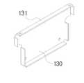
제1 엔드플레이트(120) 및 제2 엔드플레이트(130)는 복수개 적층된 배터리모듈(110)의 적층방향과 수직인 양측부에 각각 배치된다. 또한, 제1 엔드플레이트 (120) 및 제2 엔드플레이트(130)는 적어도 하나 이상의 측면이 절곡되어 형성되는 절곡부(121,131)를 포함한다. 제1 엔드플레이트(120) 및 제2 엔드플레이트(130)은 평면일 경우 외부의 힘에 의해서 변형이 일어나기 쉽기 때문에 적어도 하나 이상의 절곡부(121,131)가 형성되어 쉽게 변형이 일어나는 것을 방지하는 것이 바람직하다. 또한, 절곡부(121,131)는 배터리모듈(110)의 반대쪽으로 절곡 형성되어, 냉각홀(111)에 냉각유체가 유입 또는 배출되는데 간섭받지 않도록 형성되는 것이 바람직하다. 절곡부(121,131)가 형성되어 배터리 서브팩(100)을 다른 곳에 고정 또는 결합할 경우 손쉽게 고정할 수 있다.(도 4 참조)The
하단부재(160)는 배터리모듈(110)의 하부 및 상기 제1 및 제2 엔드플레이트(120,130)의 사이에 위치하고, 상기 제1 및 제2 엔드플레이트(120,130)에 양단면이 밀착되어 결합된다.The
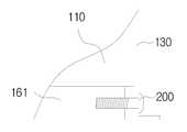
이때, 하단부재(160)는 복수개의 배터리모듈(110)이 적층된 길이보다 길이가 짧은 것을 특징으로 한다. 하단부재(160)는 복수개의 배터리모듈(110)이 적층된 길이와 동일할 경우, 가장 이상적으로 조립할 수 있지만, 배터리모듈(110)을 제작하는 과정에서 생길 수 있는 오차가 있을 수 있으며, 배터리모듈(110)을 복수개 적층시키게 되면 그 오차범위는 더 크게 됩니다. 또한, 배터리모듈(110)을 복수개 적층시킨 후 적층된 길이를 측정하여, 이에 따라서, 하단부재(160)를 제작할 수 없기 때문에, 하단부재(160)의 길이는 복수개의 배터리모듈(110)이 적층된 길이 보다 짧게 제작하여, 차이가 나는 길이를 하단부재(160)와 제1 엔드플레이트(120) 또는 제2 엔드플레이트(130)를 결합하는 결합부재(200)로 오차길이를 보상하여 조립하기 용이하게 된다.(도 7 참조)At this time, the
좀 더 상세하게는, 배터리 모듈(110)의 제작하는데 있어서, 배터리 모듈(110)의 폭이 5cm이고, 제작공차가 ㅁ0.5mm일 경우 배터리 모듈(110)을 5개 적층시킬 경우 발생하는 공차는 ㅁ2.5mm가 된다. 이때, 하단부재(160)의 길이를 25cm로 제작하는 것이 아니라, 24.75cm로 제작하게 되면, 하단부재(160)와 엔드플레이트(120,130)의 길이의 차이는 0~5mm를 되고, 결합부재(200)를 이용하여 하단부재(160)와 엔드플레이트(120,130)를 결합하게 되면 0~5mm 이격된 상태에서 조립할 수 있다.In more detail, in the manufacture of the
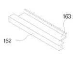
또한, 하단부재(160)는 복수개의 배터리모듈(110)을 적층방향과 평행한 바형상으로 제작되는 것이 바람직하다.(도 5 참조) 도 2에 도시된 바와 같이 하단부재(160)는 제1 하단부재(161)와 제2 하단부재(162)를 포함할 수 있다.In addition, the
배터리모듈(110)은 냉각유체가 통과할 수 있도록 냉각홀(111)이 형성되어, 냉각홀(111)로 냉각유체가 원활히 이동할 수 있도록 하단부재(160)의 간섭을 받지 않도록 냉각홀(111)이 형성되지 않는 곳에 즉, 배터리모듈(110)의 하부 외측에 각각 제1 하단부재(161)과 제2 하단부재(162)가 위치하는 것이 바람직하다.The
또한, 하단부재(160)에 배터리안착부(163)가 형성되어, 배터리모듈(110)의 모서리 부분이 배터리안착부(163)에 밀착되어 적층된다. 즉, 배터리안착부(163)는 배터리모듈(110)의 모서리 부분과 동일한 형성으로 제작된다. 이때, 배터리모듈(110)은 제1 엔드플레이트(120) 방향, 하단부재(160) 방향, 배터리안착부(163) 방향으로 밀착하여, 적층함에 따라, 배터리모듈을 손쉽게 적층할 수 있는 장점이 있다.(도 6 참조)In addition, the
제1 상단부재(140) 및 제2 상단부재(150)는 복수개 적층된 배터리모듈(110)의 적층방향과 평행한 상부모서리에 각각 위치하며, 형상이 복수개 적층된 배터리모듈(110)의 적층방향과 평행한 상부모서리와 동일한 형상으로 제작되어 밀착되어 결합되는 것이 바람직하다. 이때, 각각의 배터리모듈(110)에는 상단부재결합홀이 형성되고, 제1 상단부재(140) 및 제2 상단부재(150)에는 상단부재결합홀과 대응되는 위치에 결합홀이 형성되어 결합부재(200)가 결합홀과 상단부재결합홀을 관통하여, 상기 제1 상단부재(140) 및 제2 상단부재(150)가 복수개 적층된 배터리모듈(110)에 결합된다.The first
배터리 서브팩(100)은 각각의 배터리모듈(110)의 전극단자에 연결되는 하네스(190)를 더 포함한다. 하네스(190)는 각각의 배터리모듈(110)의 전력이 외부로 공급하기 위한, 케이블역할을 한다. 또한, 하네스(190)는 배터리모듈(110)의 PCB(Printed Circuit Board)에 연결되어, 배터리모듈(110)의 전압, 전류, 온도 등의 정보를 BMS(Battery Management System)에 전송하기 위한 케이블로 사용될 수 도 있다.The battery subpack 100 further includes a
상술한 결합부재(200)는 볼트, 나사, 피스 등 과 같이 두 개의 물체를 결합하기 위해서, 홀을 통해서 삽입하는 결합부재(200)를 의미한다.The above-described
본 발명의 일실시예에 따른 배터리 서브팩(100)은 덕트(170,180)를 더 포함할 수 있다.The battery subpack 100 according to an embodiment of the present invention may further include
덕트(170,180)는 제1 덕트(170)와 제2 덕트(180)를 포함하고, 제1 덕트(170)는 복수개의 적층된 배터리모듈(110)의 상부에 위치하여, 외부의 공기가 유입 또는 배터리모듈(110) 내의 유체가 외부로 유출될 수 있도록 형성된다. 이를 위해서, 배터리모듈(110)에 천공되는 냉각홀(111)을 완전히 덮도록 형성되며, 냉각홀(111)로 유입 또는 배출되는 냉각유체가 효율적으로 제1 덕트로 배출 또는 유입될 수 있도록 덕트 몸체는 일정각도를 가지고 형성된다. 또한, 제2 덕트(180)는 복수개의 적층된 배터리모듈(110)의 하부에 위치하여, 외부의 공기가 유입 또는 배터리모듈(110) 내의 유체가 외부로 유출될 수 있도록 형성된다. 이를 위해서, 배터리모듈(110)에 천공되는 냉각홀(111)을 완전히 덮도록 형성되며, 냉각홀(111)로 유입 또는 배출되는 냉각유체가 효율적으로 제2 덕트(180)로 배출 또는 유입될 수 있도록 덕트(170,180) 몸체는 일정각도를 가지고 형성된다.
The
도 8을 이용하여, 본 발명의 일실시예에 따른 배터리 서브팩의 조립단계를 상세히 설명한다.Referring to Figure 8, the assembly steps of the battery subpack according to an embodiment of the present invention will be described in detail.
본 발명의 일실시예에 따른 배터리 서브팩의 조립단계는 제1 결합단계(S10), 배터리모듈 안착단계(S20), 제2 결합단계(S30), 제3 결합단계(S40), 덕트 결합단계(S50), 및 하네스 결합단계(S60)를 포함한다.The assembling step of the battery subpack according to an embodiment of the present invention includes a first joining step (S10), a battery module seating step (S20), a second joining step (S30), a third joining step (S40), and a duct joining step. (S50), and a harness coupling step (S60).
제1 결합단계(S10)는 제1 엔드플레이트(120)에 하단부재(160)를 결합하는 단계로서, 제1 엔드플레이트(120)의 전면하부에 하단부재(160)를 밀착시켜, 결합부재(200)를 이용하여 결합한다.The first coupling step (S10) is a step of coupling the
배터리모듈 안착단계(S20)는 제1 결합단계(S10)에서 결합된 제1 엔드플레이트(120)와 하단부재(160)에 배터리모듈(110)을 안착하는 단계로서, 제1 엔드플레이트(120)와 하단부재(160)가 결합되어 배터리모듈(110)을 안착할 수 있는 공간이 형성되고, 배터리모듈(110)의 하부면이 하단부재(160)의 상부면에 밀착되고, 제1 엔드플레이트(120)와 인접한 배터리모듈의 일측면이 제1 엔드플레이트(120)와 밀착되게 안착되는 것이 바람직하다. 이때, 하단부재(160)에 배터리안착부(163)가 형성되어, 배터리모듈(110)의 모서리 부분이 배터리안착부(163)에 밀착되어 적층된다. 즉, 배터리안착부(163)는 배터리모듈(110)의 모서리 부분과 동일한 형성으로 제작된다. 이때, 배터리모듈(110)은 제1 엔드플레이트(120) 방향, 하단부재(160) 방향, 배터리안착부(163) 방향으로 밀착하여, 적층함에 따라, 배터리모듈을 손쉽게 적층할 수 있는 장점이 있다.
The battery module mounting step (S20) is a step of seating the
제2 결합단계(S30)는 하단부재(160)에 제2 엔드플레이트(130)를 결합하는 단계로서, 제2 엔드플레이트(130)는 제1 엔드플레이트(120)가 배터리모듈(110)에 밀착되는 면과 대응되는 면에 밀착되고, 하단부재(160)에 결합부재(200)를 이용하여 결합되는 된다. 이때, 제2 엔드플레이트(130)와 하단부재(160)는 소정의 거리가 떨어진 상태로 결합되는 것이 바람직하다. 즉, 제1 엔드플레이트(120)와 제2 엔드플레이트(130)의 거리보다 하단부재(160)가 짧게 제작되어, 배터리모듈(110)를 제작할 경우 제작오차로 인해 적층시킨 배터리모듈(110)의 길이가 정규규격보다 길거나 짧아도 조립하는데 문제가 없도록 제작되는 것이 바람직하다.The second coupling step (S30) is a step of coupling the
제3 결합단계(S40)는 복수개 적층된 배터리모듈(110)의 적층방향과 평행한 상부 모서리에 각각 제1 및 제2 상단부재(140,150)가 결합되는 단계이다.The third coupling step (S40) is a step in which the first and second
덕트 결합단계(S50)는 복수개 적층된 배터리모듈(110)의 상부 또는 하부에 덕트(170,180)를 결합하는 단계이다.The duct coupling step (S50) is a step of coupling the
하네스결합단계(S60)는 복수개 적층된 배터리모듈(110)에 하네스(190)를 결합하는 단계이다.
The harness coupling step (S60) is a step of coupling the
본 발명은 상기한 실시예에 한정되지 아니하며, 적용범위가 다양함은 물론이고, 청구범위에서 청구하는 본 발명의 요지를 벗어남이 없이 당해 본 발명이 속하는 분야에서 통상의 지식을 가진 자라면 누구든지 다양한 변형 실시가 가능한 것은 물론이다.
The present invention is not limited to the above-described embodiments, and of course, the scope of application is diverse, and anyone who has ordinary knowledge in the field to which the present invention pertains without departing from the gist of the present invention as claimed in the claims. Of course, various modifications are possible.
100 : 배터리서브팩110 : 배터리 모듈
111 : 냉각홀120 : 제1 엔드플레이트
121 : 절곡부
130 : 제2 엔드플레이트131 : 절곡부
140 : 제1 상단부재150 : 제2 상단부재
160 : 하단부재161 : 제1 하단부재
162 : 제2 하단부재163 : 배터리안착부
170 : 제1 덕트180 : 제2 덕트
190 : 하네스200 : 결합부재100: battery subpack 110: battery module
111: cooling hole 120: first end plate
121: bend
130: second end plate 131: bent portion
140: first upper member 150: second upper member
160: lower member 161: first lower member
162: second lower member 163: battery seat
170: first duct 180: second duct
190: Harness 200: Coupling member
Claims (9)
Translated fromKorean상기 복수개 적층된 배터리모듈의 적층방향과 수직인 양측면에 각각 배치되는 제1 및 제2 엔드플레이트;
상기 복수개 적층된 배터리모듈의 적층방향과 평행한 상부모서리에 각각 위치하는 제1 및 제2 상단부재; 및
상기 배터리모듈의 하부에 위치하고, 상기 제1 및 제2 엔드플레이트의 사이에 위치하여 결합부재를 통해 각각 상기 제1 엔드플레이트와 제2 엔드플레이트에 고정 결합되는 하단부재;를 포함하되,
상기 하단부재의 길이가 적층된 배터리모듈의 전체 길이 보다 짧은 길이를 갖도록 형성되어,
결합부재를 통해 제1 엔드플레이트와 제2 엔드플레이트를 상기 하단부재에 결합할 때 제1 엔드플레이트와 제2 엔드플레이트 사이의 간격을 조절할 수 있는 것을 특징으로 하는, 배터리 서브팩.
In the battery sub-pack including a plurality of battery modules are stacked with at least one battery cell unit module is embedded in series and / or parallel,
First and second end plates disposed on both sides perpendicular to the stacking direction of the plurality of stacked battery modules;
First and second upper members positioned at upper edges parallel to the stacking direction of the plurality of stacked battery modules, respectively; And
Included in the lower portion of the battery module, located between the first and second end plates, the lower member fixedly coupled to the first end plate and the second end plate through a coupling member, respectively.
The length of the lower member is formed to have a length shorter than the entire length of the stacked battery module,
When the first end plate and the second end plate are coupled to the lower member through the coupling member, it is possible to adjust the distance between the first end plate and the second end plate, the battery subpack.
상기 배터리 서브팩은 상기 배터리 모듈의 상부에 결합되는 덕트를 더 포함하고, 상기 배터리 모듈은 상하방향으로 천공되는 복수개의 냉각홀이 형성되는 배터리 서브팩.
According to claim 1,
The battery sub-pack further includes a duct coupled to the upper portion of the battery module, the battery module is a battery sub-pack is formed with a plurality of cooling holes perforated in the vertical direction.
상기 배터리 서브팩은 상기 배터리모듈의 전극단자 또는 PCB에 연결되는 하네스를 포함하는 배터리 서브팩.
According to claim 1,
The battery subpack is a battery subpack including a harness connected to the electrode terminal or the PCB of the battery module.
상기 하단부재는 측면에 상기 배터리모듈이 안착하기 위한 배터리안착부가 위치되는 배터리 서브팩.
According to claim 1,
The lower member is a battery subpack in which a battery seating portion for seating the battery module on the side.
상기 하단부재는 상기 복수개의 배터리셀의 적층방향과 평행한 바 형상으로 제작되는 배터리 서브팩.
According to claim 1,
The lower member is a battery sub-pack manufactured in a bar shape parallel to the stacking direction of the plurality of battery cells.
상기 제1 엔드플레이트 및 제2 엔드플레이트는 적어도 하나 이상의 측면이 배터리모듈의 반대 방향으로 절곡되는 절곡부를 포함하는 배터리 서브팩.
According to claim 1,
The first end plate and the second end plate is a battery sub-pack including at least one side portion bent in the opposite direction of the battery module.
상기 제1 엔드플레이트와 상기 제2 엔드플레이트에는 결합홀이 형성되고,
상기 결합부재는 상기 제1 엔드플레이트 및 상기 제2 엔드플레이트의 결합홀을 관통한 후 마주보는 상기 하단부재와 결합되는 것을 특징으로 하는 배터리 서브팩.
According to claim 1,
A coupling hole is formed in the first end plate and the second end plate,
The coupling member is a battery sub-pack, characterized in that coupled to the lower member facing after passing through the coupling hole of the first end plate and the second end plate.
제1 엔드플레이트에 하단부재를 결합하는 제1 결합단계;
상기 제1 결합단계에서 결합된 상기 제1 엔드플레이트와 상기 하단부재에 복수개의 배터리모듈을 안착하는 배터리모듈 안착단계;
상기 하단부재에 제2 엔드플레이트를 결합하는 제2 결합단계;
상기 복수개의 적층된 배터리모듈의 적층방향과 평행한 상부 모서리에 각각 제1 및 제2 상단부재를 결합하는 제3 결합단계;
상기 복수개 적층된 배터리모듈의 상부에 덕트를 결합하는 덕트 결합단계; 및
상기 복수개 적층된 배터리 모듈에 하네스를 결합하는 하네스 결합단계;
를 포함하는 배터리 서브팩 조립방법.In the battery sub-pack assembly method of assembling the battery sub-pack of claim 1,
A first coupling step of coupling the lower member to the first end plate;
A battery module mounting step of seating a plurality of battery modules on the first end plate and the lower member combined in the first combining step;
A second coupling step of coupling a second end plate to the lower member;
A third coupling step of coupling first and second upper members to upper edges parallel to the stacking direction of the plurality of stacked battery modules, respectively;
A duct joining step of joining a duct to an upper portion of the plurality of stacked battery modules; And
A harness coupling step of coupling a harness to the plurality of stacked battery modules;
Battery subpack assembly method comprising a.
Priority Applications (1)
| Application Number | Priority Date | Filing Date | Title |
|---|---|---|---|
| KR1020120140080AKR102122926B1 (en) | 2012-12-05 | 2012-12-05 | Battery Sub-Pack and a Method for manufacturing the same |
Applications Claiming Priority (1)
| Application Number | Priority Date | Filing Date | Title |
|---|---|---|---|
| KR1020120140080AKR102122926B1 (en) | 2012-12-05 | 2012-12-05 | Battery Sub-Pack and a Method for manufacturing the same |
Publications (2)
| Publication Number | Publication Date |
|---|---|
| KR20140074411A KR20140074411A (en) | 2014-06-18 |
| KR102122926B1true KR102122926B1 (en) | 2020-06-15 |
Family
ID=51127501
Family Applications (1)
| Application Number | Title | Priority Date | Filing Date |
|---|---|---|---|
| KR1020120140080AActiveKR102122926B1 (en) | 2012-12-05 | 2012-12-05 | Battery Sub-Pack and a Method for manufacturing the same |
Country Status (1)
| Country | Link |
|---|---|
| KR (1) | KR102122926B1 (en) |
Families Citing this family (2)
| Publication number | Priority date | Publication date | Assignee | Title |
|---|---|---|---|---|
| US10637111B2 (en) | 2015-10-02 | 2020-04-28 | Lg Chem, Ltd. | Battery module having improved cooling duct sealing properties |
| KR101761678B1 (en)* | 2017-02-24 | 2017-07-27 | 엠에이치기술개발 주식회사 | Manufacturing method of cooling apparatus for battery |
Family Cites Families (5)
| Publication number | Priority date | Publication date | Assignee | Title |
|---|---|---|---|---|
| US20110165451A1 (en) | 2010-01-05 | 2011-07-07 | Myung-Chul Kim | Battery pack |
| JP5734450B2 (en)* | 2010-11-22 | 2015-06-17 | エルジー・ケム・リミテッド | Small structure battery pack |
| KR101252950B1 (en)* | 2011-04-21 | 2013-04-15 | 로베르트 보쉬 게엠베하 | Battery module providing improved fixing structure for end plate |
| KR101252935B1 (en)* | 2011-04-21 | 2013-04-09 | 로베르트 보쉬 게엠베하 | Battery module |
| CN103493244B (en)* | 2011-05-19 | 2016-04-27 | 株式会社Lg化学 | Battery pack with high structural stability |
- 2012
- 2012-12-05KRKR1020120140080Apatent/KR102122926B1/enactiveActive
Also Published As
| Publication number | Publication date |
|---|---|
| KR20140074411A (en) | 2014-06-18 |
Similar Documents
| Publication | Publication Date | Title |
|---|---|---|
| KR101909215B1 (en) | Battery submodule carrier, battery submodule, battery system and vehicle | |
| EP2571078B1 (en) | Battery module | |
| US9768427B2 (en) | Battery module assembly of improved reliability and battery pack employed with the same | |
| KR102117848B1 (en) | Battery Module and Manufacturing the Same | |
| US7947389B2 (en) | Cartridge frame with connectors for battery pack | |
| KR101913786B1 (en) | Battery Module for Direct Connection Structure Between Terminal Plate and Battery Management System | |
| KR102640328B1 (en) | Large module of battery | |
| KR101305218B1 (en) | Battery Module Having Fixing Member and Coupling Member, and Battery Pack Employed with the Same | |
| WO2010087651A4 (en) | Cell cartridge with a composite intercell connecting net structure | |
| KR101326182B1 (en) | Battery Module Based upon Unit Module Having External Covering Member and Cartridge | |
| KR20120077635A (en) | Pouch Type Cell Case | |
| CN104425782A (en) | Battery pack | |
| KR20170027543A (en) | Battery Module having an improved coupling structure | |
| KR20170127273A (en) | Submodule and battery module comprising the submodule | |
| KR102235650B1 (en) | Secondary battery module, and secondary battery pack including the same | |
| KR20140015859A (en) | Hermetic battery module | |
| KR101761825B1 (en) | Battery module, and battery pack including the same | |
| KR20170037157A (en) | Pouch-typed secondary battery comprising modified leads and battery module comprising the same | |
| JPWO2018143464A1 (en) | Battery module, method of manufacturing battery module | |
| US9595743B2 (en) | Battery module | |
| KR101810657B1 (en) | Cartridge Having Fixing Bracket and Battery Module and Pack Including the Same | |
| KR102050291B1 (en) | Battery Module | |
| KR101305229B1 (en) | Unit Module Having External Covering Member and Heat Dissipation Member and Battery Module Comprising the Same | |
| KR102122926B1 (en) | Battery Sub-Pack and a Method for manufacturing the same | |
| JP5290662B2 (en) | Battery module external short circuit system |
Legal Events
| Date | Code | Title | Description |
|---|---|---|---|
| PA0109 | Patent application | Patent event code:PA01091R01D Comment text:Patent Application Patent event date:20121205 | |
| PG1501 | Laying open of application | ||
| A201 | Request for examination | ||
| PA0201 | Request for examination | Patent event code:PA02012R01D Patent event date:20171128 Comment text:Request for Examination of Application Patent event code:PA02011R01I Patent event date:20121205 Comment text:Patent Application | |
| E902 | Notification of reason for refusal | ||
| PE0902 | Notice of grounds for rejection | Comment text:Notification of reason for refusal Patent event date:20190320 Patent event code:PE09021S01D | |
| E902 | Notification of reason for refusal | ||
| PE0902 | Notice of grounds for rejection | Comment text:Notification of reason for refusal Patent event date:20191128 Patent event code:PE09021S01D | |
| E701 | Decision to grant or registration of patent right | ||
| PE0701 | Decision of registration | Patent event code:PE07011S01D Comment text:Decision to Grant Registration Patent event date:20200311 | |
| GRNT | Written decision to grant | ||
| PR0701 | Registration of establishment | Comment text:Registration of Establishment Patent event date:20200609 Patent event code:PR07011E01D | |
| PR1002 | Payment of registration fee | Payment date:20200610 End annual number:3 Start annual number:1 | |
| PG1601 | Publication of registration | ||
| PR1001 | Payment of annual fee | Payment date:20230313 Start annual number:4 End annual number:4 | |
| PR1001 | Payment of annual fee | Payment date:20240312 Start annual number:5 End annual number:5 |