KR102119637B1 - Multistage high capacity filter and depth coalescing media system - Google Patents
Multistage high capacity filter and depth coalescing media systemDownload PDFInfo
- Publication number
- KR102119637B1 KR102119637B1KR1020157020039AKR20157020039AKR102119637B1KR 102119637 B1KR102119637 B1KR 102119637B1KR 1020157020039 AKR1020157020039 AKR 1020157020039AKR 20157020039 AKR20157020039 AKR 20157020039AKR 102119637 B1KR102119637 B1KR 102119637B1
- Authority
- KR
- South Korea
- Prior art keywords
- filter
- stage
- fluid
- stage filter
- housing
- Prior art date
- Legal status (The legal status is an assumption and is not a legal conclusion. Google has not performed a legal analysis and makes no representation as to the accuracy of the status listed.)
- Active
Links
- 239000012530fluidSubstances0.000claimsabstractdescription78
- XLYOFNOQVPJJNP-UHFFFAOYSA-NwaterSubstancesOXLYOFNOQVPJJNP-UHFFFAOYSA-N0.000claimsabstractdescription32
- 238000001914filtrationMethods0.000claimsabstractdescription7
- 238000000034methodMethods0.000claimsdescription11
- 238000007599dischargingMethods0.000claimsdescription4
- 239000003795chemical substances by applicationSubstances0.000claims1
- 239000000839emulsionSubstances0.000abstractdescription4
- 238000011144upstream manufacturingMethods0.000abstractdescription4
- 239000000446fuelSubstances0.000description29
- 239000000853adhesiveSubstances0.000description9
- 230000001070adhesive effectEffects0.000description9
- 230000000712assemblyEffects0.000description8
- 238000000429assemblyMethods0.000description8
- 230000004888barrier functionEffects0.000description5
- 230000002209hydrophobic effectEffects0.000description4
- 239000000356contaminantSubstances0.000description2
- 239000002828fuel tankSubstances0.000description2
- 239000011521glassSubstances0.000description2
- 230000005484gravityEffects0.000description2
- 239000007788liquidSubstances0.000description2
- 239000002121nanofiberSubstances0.000description2
- 238000000926separation methodMethods0.000description2
- 239000000428dustSubstances0.000description1
- 230000000694effectsEffects0.000description1
- 238000001125extrusionMethods0.000description1
- 239000012535impuritySubstances0.000description1
- 238000002347injectionMethods0.000description1
- 239000007924injectionSubstances0.000description1
- 239000000463materialSubstances0.000description1
- 239000000203mixtureSubstances0.000description1
- 238000012986modificationMethods0.000description1
- 230000004048modificationEffects0.000description1
- 230000037452primingEffects0.000description1
- 239000000523sampleSubstances0.000description1
Images


Classifications
- F—MECHANICAL ENGINEERING; LIGHTING; HEATING; WEAPONS; BLASTING
- F02—COMBUSTION ENGINES; HOT-GAS OR COMBUSTION-PRODUCT ENGINE PLANTS
- F02M—SUPPLYING COMBUSTION ENGINES IN GENERAL WITH COMBUSTIBLE MIXTURES OR CONSTITUENTS THEREOF
- F02M37/00—Apparatus or systems for feeding liquid fuel from storage containers to carburettors or fuel-injection apparatus; Arrangements for purifying liquid fuel specially adapted for, or arranged on, internal-combustion engines
- F02M37/22—Arrangements for purifying liquid fuel specially adapted for, or arranged on, internal-combustion engines, e.g. arrangements in the feeding system
- F02M37/24—Arrangements for purifying liquid fuel specially adapted for, or arranged on, internal-combustion engines, e.g. arrangements in the feeding system characterised by water separating means
- B—PERFORMING OPERATIONS; TRANSPORTING
- B01—PHYSICAL OR CHEMICAL PROCESSES OR APPARATUS IN GENERAL
- B01D—SEPARATION
- B01D27/00—Cartridge filters of the throw-away type
- B01D27/04—Cartridge filters of the throw-away type with cartridges made of a piece of unitary material, e.g. filter paper
- B01D27/06—Cartridge filters of the throw-away type with cartridges made of a piece of unitary material, e.g. filter paper with corrugated, folded or wound material
- B01D27/07—Cartridge filters of the throw-away type with cartridges made of a piece of unitary material, e.g. filter paper with corrugated, folded or wound material having a coaxial stream through the filtering element
- B—PERFORMING OPERATIONS; TRANSPORTING
- B01—PHYSICAL OR CHEMICAL PROCESSES OR APPARATUS IN GENERAL
- B01D—SEPARATION
- B01D36/00—Filter circuits or combinations of filters with other separating devices
- B01D36/003—Filters in combination with devices for the removal of liquids
- B—PERFORMING OPERATIONS; TRANSPORTING
- B01—PHYSICAL OR CHEMICAL PROCESSES OR APPARATUS IN GENERAL
- B01D—SEPARATION
- B01D36/00—Filter circuits or combinations of filters with other separating devices
- B01D36/02—Combinations of filters of different kinds
- B—PERFORMING OPERATIONS; TRANSPORTING
- B01—PHYSICAL OR CHEMICAL PROCESSES OR APPARATUS IN GENERAL
- B01D—SEPARATION
- B01D36/00—Filter circuits or combinations of filters with other separating devices
- B01D36/04—Combinations of filters with settling tanks
- F—MECHANICAL ENGINEERING; LIGHTING; HEATING; WEAPONS; BLASTING
- F02—COMBUSTION ENGINES; HOT-GAS OR COMBUSTION-PRODUCT ENGINE PLANTS
- F02M—SUPPLYING COMBUSTION ENGINES IN GENERAL WITH COMBUSTIBLE MIXTURES OR CONSTITUENTS THEREOF
- F02M37/00—Apparatus or systems for feeding liquid fuel from storage containers to carburettors or fuel-injection apparatus; Arrangements for purifying liquid fuel specially adapted for, or arranged on, internal-combustion engines
- F02M37/22—Arrangements for purifying liquid fuel specially adapted for, or arranged on, internal-combustion engines, e.g. arrangements in the feeding system
- F02M37/24—Arrangements for purifying liquid fuel specially adapted for, or arranged on, internal-combustion engines, e.g. arrangements in the feeding system characterised by water separating means
- F02M37/26—Arrangements for purifying liquid fuel specially adapted for, or arranged on, internal-combustion engines, e.g. arrangements in the feeding system characterised by water separating means with water detection means
- F—MECHANICAL ENGINEERING; LIGHTING; HEATING; WEAPONS; BLASTING
- F02—COMBUSTION ENGINES; HOT-GAS OR COMBUSTION-PRODUCT ENGINE PLANTS
- F02M—SUPPLYING COMBUSTION ENGINES IN GENERAL WITH COMBUSTIBLE MIXTURES OR CONSTITUENTS THEREOF
- F02M37/00—Apparatus or systems for feeding liquid fuel from storage containers to carburettors or fuel-injection apparatus; Arrangements for purifying liquid fuel specially adapted for, or arranged on, internal-combustion engines
- F02M37/22—Arrangements for purifying liquid fuel specially adapted for, or arranged on, internal-combustion engines, e.g. arrangements in the feeding system
- F02M37/32—Arrangements for purifying liquid fuel specially adapted for, or arranged on, internal-combustion engines, e.g. arrangements in the feeding system characterised by filters or filter arrangements
Landscapes
- Engineering & Computer Science (AREA)
- Chemical & Material Sciences (AREA)
- Chemical Kinetics & Catalysis (AREA)
- Combustion & Propulsion (AREA)
- Mechanical Engineering (AREA)
- General Engineering & Computer Science (AREA)
- Filtration Of Liquid (AREA)
- Filtering Of Dispersed Particles In Gases (AREA)
Abstract
Translated fromKoreanDescription
Translated fromKorean본 출원은 2013년 1월 15일자로 출원된 미국 가출원 61/752,553호를 우선권으로 하며, 이는 참고로 본원에 편입된다.
This application has priority to U.S. Provisional Application No. 61/752,553 filed on January 15, 2013, which is incorporated herein by reference.
본 발명은 일반적으로 유체 필터 및 조립체에 관한 것으로서, 더욱 상세하게 차량 연료 시스템용 연료 필터 및 조립체에 관한 것이다.
The present invention relates generally to fluid filters and assemblies, and more particularly to fuel filters and assemblies for vehicle fuel systems.
예컨대 차량 등을 위한 소정의 연료 시스템에서, 상기 시스템, 예컨대 연료 탱크로부터 엔진으로 연료를 이동시키도록 펌프가 제공된다. 필터 요소는 펌프의 하류에(압력측 상에) 제공됨으로써, 하류의 구성요소를 보호할 수 있다. 필터 요소는 액체 및 불순물을 포함하는 유체를 여과하는데 이용될 수 있다. 예를 들면, 필터는 습기 민감성 구성요소(예컨대, 연료 분사 장비)에 부정적인 영향을 회피하도록 액체 연료로부터 물을 제거하는데 종종 이용된다. 추가적으로 또는 변형적으로, 필터는 동일하거나 또는 다른 구성요소(예컨대, 엔진 부품)에 손상될 수 있는 오염물을 제거한다.
In certain fuel systems, such as for vehicles, a pump is provided to move fuel from the system, such as a fuel tank, to the engine. The filter element is provided downstream (on the pressure side) of the pump, thereby protecting downstream components. The filter element can be used to filter fluids containing liquids and impurities. For example, filters are often used to remove water from liquid fuel to avoid negative effects on moisture sensitive components (eg, fuel injection equipment). Additionally or alternatively, the filter removes contaminants that can be damaged by the same or different components (eg, engine parts).
본 발명은 필터를 통해 흐르는 유체로부터 미립자를 여과하는 제1 스테이지 필터와, 상기 유체로부터 물을 합치하는 상기 제1 스테이지 필터의 하류에 있는 제2 스테이지 필터를 갖는 필터 조립체를 제공한다. 상기 제2 스테이지 필터의 상류에 상기 제1 스테이지 필터를 제공함으로써, 미립자 여과 용량 및 효율이 제공되는 한편, 상기 제2 스테이지 필터를 미립자로부터 보호할 수 있다. 상기 제2 스테이지 필터를 미립자로부터 보호하는 것은 상기 제2 스테이지 필터의 수명을 연장되게 하는 한편, 상기 필터 조립체 내에서의 효율적인 에멀젼 제거를 제공한다.
The present invention provides a filter assembly having a first stage filter that filters particulates from a fluid flowing through a filter, and a second stage filter downstream of the first stage filter that matches water from the fluid. By providing the first stage filter upstream of the second stage filter, particulate filtration capacity and efficiency are provided, while the second stage filter can be protected from particulates. Protecting the second stage filter from particulates extends the life of the second stage filter, while providing efficient emulsion removal within the filter assembly.
본 발명의 일 관점에 의하면, 필터 헤드에 결합되도록 구성된 필터 조립체가 제공된다. 상기 필터 조립체는 중심축을 둘러싸며, 제1 및 제2 단부와, 그 사이에 형성된 내부 챔버를 갖는 하우징; 및 상기 하우징의 내부 챔버 내에 배치된 필터 요소를 구비하며, 상기 필터 요소는, 상기 중심축을 둘러싸며 중앙 캐비티를 형성하는 제1 스테이지 필터; 상기 제1 스테이지 필터의 하류에 있으며, 상기 중심축을 둘러싸며 중앙 캐비티를 형성하는 제2 스테이지 필터; 및 상기 제1 및 제2 스테이지 필터의 중앙 캐비티 내에 배치되는 중앙 튜브를 구비한다. 상기 하우징의 제1 단부로부터 상기 제2 단부를 향해 미립자가 유체로부터 여과되는 상기 제1 스테이지 필터 내로 유체가 흐르고, 상기 제1 스테이지 필터로부터 물이 상기 유체로부터 합치(coalesced)되는 상기 제2 스테이지 필터 내로 축방향으로 상기 유체가 흐른 다음, 상기 중앙 튜브를 통해 상기 제2 스테이지 필터로부터 상기 하우징의 제1 단부를 향해 상기 유체가 흐른다
According to one aspect of the present invention, a filter assembly configured to be coupled to a filter head is provided. The filter assembly includes a housing surrounding the central axis and having first and second ends and an inner chamber formed therebetween; And a filter element disposed in the inner chamber of the housing, the filter element comprising: a first stage filter surrounding the central axis and forming a central cavity; A second stage filter downstream of the first stage filter and surrounding the central axis to form a central cavity; And a central tube disposed in the central cavity of the first and second stage filters. A second stage filter in which fluid flows from the first end of the housing toward the second end into the first stage filter in which particulates are filtered from the fluid, and water from the first stage filter coalesced from the fluid The fluid flows axially into, and then the fluid flows through the central tube from the second stage filter toward the first end of the housing.
상기 필터 요소는 상기 제2 스테이지 필터로부터 유체를 수용하여 합치된 물 액적이 하측방향으로 이동하게 하면서 상기 중앙 튜브 내로 상기 유체를 배출하도록 배치된 제3 스테이지 필터를 더 구비할 수 있다.
The filter element may further include a third stage filter arranged to receive fluid from the second stage filter and allow the matched water droplets to move downwards while discharging the fluid into the central tube.
상기 제1 및 제2 스테이지 필터는, 상기 제1 및 제2 스테이지 필터를 상기 하우징에 유체식으로 밀봉하도록 상기 하우징의 내부면에 결합된 외부면을 각각 가질 수 있다.
The first and second stage filters may each have an outer surface coupled to the inner surface of the housing to fluidly seal the first and second stage filters to the housing.
상기 제1 및 제2 스테이지 필터는 상기 중앙 튜브에 유체식으로 밀봉될 수 있다.
The first and second stage filters may be fluidly sealed to the central tube.
상기 제1 스테이지 필터는 상기 필터 요소를 통해 흐르는 유체로부터 미립자를 제거하기 위해 상기 내부 챔버 내에서 상기 제1 단부에 근접하게 배치될 수 있고, 상기 제2 스테이지 필터는 상기 필터 요소를 통해 흐르는 상기 유체 내의 물을 합치하기 위해 상기 내부 챔버 내에 상기 제2 단부에 근접하게 배치될 수 있다.
The first stage filter can be disposed proximate the first end in the inner chamber to remove particulates from the fluid flowing through the filter element, the second stage filter being the fluid flowing through the filter element It may be disposed proximate the second end in the inner chamber to match the water in the inner.
상기 필터 조립체는 상기 하우징의 제2 단부에 근접한 엔드 캡을 더 구비할 수 있으며, 상기 엔드 캡은 상기 중앙 튜브의 하단부에 결합된다.
The filter assembly may further include an end cap proximate the second end of the housing, the end cap being coupled to the lower end of the center tube.
본 발명의 다른 관점에 의하면, 필터 헤드에 결합되도록 구성된 필터 조립체는, 상단부 및 하단부와, 그 사이에 형성된 챔버를 갖는 하우징; 및 상기 하우징의 내부 챔버 내에 배치된 필터 요소를 구비한다. 상기 필터 요소는, 중앙 캐비티를 형성하며, 상기 하우징의 내부면에 결합되는 외부면을 갖는 제1 스테이지 필터; 상기 제1 스테이지 필터의 하류에 있으며, 중앙 캐비티를 형성하고 상기 하우징의 내부면에 결합되는 외부면을 갖는 제2 스테이지 필터; 및 상기 제1 및 제2 스테이지 필터의 중앙 캐비티 내에 배치되며, 상기 제1 및 제2 스테이지 필터에 결합되는 중앙 튜브로서, 상기 중앙 튜브는 상단부 및 하단부를 갖고 상기 상단부와 하단부를 통해 유체 흐름 경로를 형성하는, 상기 중앙 튜브; 및 상기 중앙 튜브의 하단부에 배치되는 제3 스테이지 필터를 구비한다.
According to another aspect of the invention, a filter assembly configured to be coupled to a filter head includes: a housing having an upper portion and a lower portion, and a chamber formed therebetween; And a filter element disposed in the inner chamber of the housing. The filter element includes a first stage filter forming a central cavity and having an outer surface coupled to the inner surface of the housing; A second stage filter downstream of the first stage filter, having a central cavity and having an outer surface coupled to the inner surface of the housing; And a central tube disposed in the central cavity of the first and second stage filters and coupled to the first and second stage filters, wherein the central tube has upper and lower ends and a fluid flow path through the upper and lower ends. Forming, said central tube; And a third stage filter disposed at a lower end of the central tube.
상기 하우징의 제1 단부로부터 상기 제1 스테이지 필터, 상기 제2 스테이지 필터, 상기 제3 스테이지 필터를 통해, 그 다음 상기 중앙 튜브 내의 상기 유체 흐름 경로를 따라 유체가 흐른다.
Fluid flows from the first end of the housing through the first stage filter, the second stage filter, and the third stage filter, then along the fluid flow path in the central tube.
상기 제1 스테이지 필터는 상기 필터 요소를 통해 흐르는 유체로부터 미립자를 제거하기 위해 상기 내부 챔버 내에서 상기 제1 단부에 근접하게 배치될 수 있고, 상기 제2 스테이지 필터는 상기 필터 요소를 통해 흐르는 상기 유체 내의 물을 합치하기 위해 상기 내부 챔버 내에 상기 제2 단부에 근접하게 배치될 수 있다.
The first stage filter can be disposed proximate the first end in the inner chamber to remove particulates from the fluid flowing through the filter element, the second stage filter being the fluid flowing through the filter element It may be disposed proximate the second end in the inner chamber to match the water in the inner.
상기 제1 및 제2 스테이지 필터는 환상 롤형 필터 요소일 수 있다.
The first and second stage filters may be annular roll type filter elements.
상기 필터 조립체는 상기 하우징의 제2 단부에 근접한 엔드 캡을 더 구비할 수 있으며, 상기 엔드 캡은 상기 중앙 튜브의 하단부에 결합된다.
The filter assembly may further include an end cap proximate the second end of the housing, the end cap being coupled to the lower end of the center tube.
본 발명의 또 다른 관점에 의하면, 필터 헤드에 결합되도록 구성된 필터 조립체는, 제1 및 제2 단부와, 그 사이에 형성된 챔버를 갖는 하우징; 및 상기 하우징의 내부 챔버 내에 배치된 필터 요소를 구비한다. 상기 필터 요소는, 중앙 캐비티를 형성하며, 상기 필터 요소를 통해 흐르는 유체로부터 미립자를 제거하기 위해 상기 내부 챔버 내에서 상기 제1 단부에 근접하게 배치되는 제1 스테이지 필터; 중앙 캐비티를 형성하고 상기 필터 요소를 통해 흐르는 상기 유체 내의 물을 합치하기 위해 상기 내부 챔버 내에 상기 제2 단부에 근접하게 배치되는 제2 스테이지 필터; 및 상기 제2 스테이지 필터로부터 유체를 수용하여 합치된 물 액적이 하측방향으로 이동하게 하면서 상기 중앙 튜브 내로 상기 유체를 배출하도록 배치되는 제3 스테이지 필터를 구비한다.
According to another aspect of the invention, a filter assembly configured to be coupled to a filter head comprises: a housing having first and second ends and a chamber formed therebetween; And a filter element disposed in the inner chamber of the housing. The filter element includes: a first stage filter forming a central cavity and disposed proximate to the first end in the inner chamber to remove particulates from fluid flowing through the filter element; A second stage filter disposed proximate to the second end in the inner chamber to form a central cavity and to match water in the fluid flowing through the filter element; And a third stage filter arranged to receive the fluid from the second stage filter and discharge the fluid into the central tube while allowing the combined water droplets to move downward.
본 발명에 따른 전술한 필터 조립체 등은 하기의 특징 중 하나 이상을 선택적으로 특징으로 할 수 있다.
The above-described filter assembly or the like according to the present invention may selectively feature one or more of the following features.
상기 필터 조립체는 상기 제1 및 제2 스테이지 필터의 중앙 캐비티 내에 배치된 중앙 튜브를 더 구비할 수 있다.
The filter assembly may further include a central tube disposed within the central cavity of the first and second stage filters.
상기 제3 스테이지 필터는 상기 제2 스테이지 필터로부터 유체를 수용하여 상기 중앙 튜브 내로 상기 유체를 배출하도록 배치될 수 있다.
The third stage filter may be arranged to receive fluid from the second stage filter and discharge the fluid into the central tube.
상기 제3 스테이지 필터는 상기 중앙 튜브로부터 하측방향으로 연장될 수 있다.
The third stage filter may extend downward from the center tube.
상기 제3 스테이지 필터는 상기 중앙 튜브 내에 상측방향으로 연장될 수 있다.
The third stage filter may extend upward in the central tube.
상기 제3 스테이지 필터는 상기 제2 스테이지 필터의 반경방향 내측에 배치될 수 있다.
The third stage filter may be disposed radially inside the second stage filter.
상기 필터 조립체는 상기 하우징의 제1 단부에 결합된 커버를 더 구비할 수 있으며, 상기 커버는 상기 제1 스테이지 필터에 유체를 지향시키는 하나 이상의 입구 통로와, 유체를 배출하는 하나 이상의 출구 통로를 구비한다.
The filter assembly may further include a cover coupled to the first end of the housing, the cover having at least one inlet passage directing fluid to the first stage filter and at least one outlet passage discharging fluid. do.
상기 입구 통로는 상기 출구 통로로부터 반경방향 외측으로 이격될 수 있다.
The inlet passage may be spaced radially outwardly from the outlet passage.
상기 필터 조립체는 상기 제1 스테이지 필터에 도입되는 흐름을 상기 중앙 튜브에서 나오는 흐름과 격리하도록 상기 중앙 튜브의 상단부에 결합된 개스킷을 더 구비할 수 있다.
The filter assembly may further include a gasket coupled to the upper end of the central tube to isolate the flow introduced into the first stage filter from the flow exiting the central tube.
상기 필터 조립체는 상기 하우징의 제2 단부에 근접한 엔드 캡을 더 구비할 수 있으며, 상기 엔드 캡은 상기 중앙 튜브의 하단부에 결합된다.
The filter assembly may further include an end cap proximate the second end of the housing, the end cap being coupled to the lower end of the center tube.
상기 제1 및 제2 스테이지 필터는 환상 롤식 필터 요소(annular rolled filter elements)일 수 있고, 상기 제3 스테이지 필터는 소수성 배리어일 수 있다.
The first and second stage filters may be annular rolled filter elements, and the third stage filter may be a hydrophobic barrier.
이하, 본 발명의 전술한 특징 및 다른 특징은 첨부한 도면을 참조하여 더욱 상세하게 기술된다.
Hereinafter, the above-described features and other features of the present invention will be described in more detail with reference to the accompanying drawings.
도 1은 본 발명에 따른 예시적인 필터 조립체의 사시도,
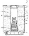
도 2는 예시적인 필터 조립체의 단면도,
도 3은 예시적인 필터 조립체의 단면도,
도 4는 본 발명에 따른 또 다른 예시적인 필터 조립체의 단면도,
도 5는 도 4의 필터 조립체의 하부 단면도,
도 6은 본 발명에 따른 또 다른 예시적인 필터 조립체의 단면도,
도 7은 본 발명에 따른 또 다른 예시적인 필터 조립체의 단면도.1 is a perspective view of an exemplary filter assembly according to the invention,
2 is a cross-sectional view of an exemplary filter assembly,
3 is a cross-sectional view of an exemplary filter assembly,
4 is a cross-sectional view of another exemplary filter assembly according to the present invention,
5 is a bottom cross-sectional view of the filter assembly of FIG. 4,
6 is a cross-sectional view of another exemplary filter assembly according to the present invention,
7 is a cross-sectional view of another exemplary filter assembly in accordance with the present invention.
본 출원의 원리는 유체 시스템으로부터 미립자 및 다른 오염물을, 예컨대 차량용 연료 시스템 내의 연료 스트림으로부터 제거하기 위한 필터 조립체에 특정한 적용을 가지며, 본란에서 간략하게 후술될 것이다. 물론, 본 발명의 원리는 유체로부터 미립자 및/또는 물을, 예컨대 항공기 내의 유압 유체로부터 제거하는 것이 바람직한 다른 필터 조립체에 적용될 수 있음을 이해할 것이다.
The principles of the present application have particular application to filter assemblies for removing particulates and other contaminants from fluid systems, such as from fuel streams in automotive fuel systems, and will be briefly described below in this section. Of course, it will be understood that the principles of the present invention can be applied to other filter assemblies where it is desirable to remove particulates and/or water from a fluid, such as hydraulic fluid in an aircraft.
도면 중 도 1 및 2를 상세하게 참조하면, 필터 조립체는 참조부호 "10"으로 지칭된다. 필터 조립체(10)는 차량용 연료 시스템을 통해, 예컨대 탱크로부터 엔진으로 연료를 이동시키기 위한 펌프의 압력측 상에서 하류에 위치될 수 있다. 물론, 필터 조립체의 다른 위치 및 적용이 가능하다.
1 and 2 of the drawings, the filter assembly is denoted by reference numeral "10". The filter assembly 10 can be located downstream through the vehicle fuel system, for example on the pressure side of the pump for moving fuel from the tank to the engine. Of course, other positions and applications of the filter assembly are possible.
필터 조립체(10)는 제1 및 제2 단부, 특히 상하단부(14, 16)와, 그 사이에 형성된 내부 챔버(18)를 갖는 하우징(12); 및 상기 내부 챔버(18) 내에 배치되는 필터 요소(20)를 구비한다. 중심축(A-A)을 둘러싸는 하우징(12)은 제1 단부(14)에서 폐쇄되고 제2 단부(16)에서 개방되는 원통형 캐니스터일 수 있다. 예를 들면, 하우징(12)은 바디(22)와, 상기 바디(22)에 임의의 방식, 예컨대 제1 단부(14)를 폐쇄하는 쓰레드식 연결에 의해 바디(22)에 결합되는 커버(24)를 구비할 수 있다. 커버(24)는 하나 이상의 개구(26), 예컨대 내부 챔버(18)에 들어오는 유체를 위한 커버(24)의 외측부에 복수의 원주방향으로 이격된 개구를 구비할 수 있다. 또한, 커버(24)는 내부 챔버(18)에서 나오는 유체를 위해 개구(26)로부터 반경방향 내측으로 이격된 하나 이상의 개구(28)를 구비할 수 있다. 유체(예컨대, 연료)는 임의의 적절한 방식으로 하우징(12)에 결합될 수 있는 필터 헤드로부터 개구(26)에 들어오고, 그 연료는 물과 미립자가 연료로부터 제거되는 필터 요소(20)를 통해 흐른다. 그 다음, 연료는 개구(28)를 통해 하우징(12)에서 나와서 필터 헤드 내로 흐른다.
The filter assembly 10 comprises a
필터 요소(20)에 의해 연료로부터 합치된 물은 하측방향으로 흘러 하우징(12)의 제2 단부(16) 외부로 그리고 임의의 적절한 방식으로 하우징(12)에 결합된 저장기 내로 흐른다. 예를 들면, 하우징(12)은 제2 단부(16)에 쓰레드를 구비하거나 또는 쓰레드형 부재, 예컨대 저장기 상의 쓰레드와 정합하기 위해 쓰레드(32)를 갖는 부재(30)에 결합될 수 있다. 저장기가 충만하거나 또는 사전결정된 레벨에 있을 때, 필터 요소(20)로부터 저장기 내에 수용되는 물은 임의의 적절한 방식으로 드레인을 통해 드레인될 수 있다. 유체 레벨은 저장기 내에 제공된 적절한 센서에 의해 결정될 수 있다.
The water congruent from the fuel by the
필터 요소(20)를 상세하게 참조하면, 필터 요소(20)는 중심축을 둘러싸며 중앙 캐비티를 형성하는 제1 스테이지 필터(40)와, 상기 제1 스테이지 필터(40)의 하류에 있는 제2 스테이지 필터(42)를 구비하며, 상기 제2 스테이지 필터(42)는 중심축을 둘러싸며 중앙 캐비티를 형성한다. 제1 스테이지 필터(40)는 임의의 적절한 필터, 예컨대 롤형 필터 요소, 환상 롤형 필터 요소일 수 있다. 제2 스테이지 필터(42)는 임의의 적절한 필터, 예컨대 롤형 필터 요소, 환상 롤형 필터요소, 글라스 프리 나노파이버 매체, 주름형 매체, 깊이 합치 매체, 하나 이상의 디스크, 글라스 프리 나노파이버 디스크, 압출 매체 등일 수도 있다.
Referring to the
제1 스테이지 필터(40)는 필터 요소(40)를 통해 흐르는 유체로부터 미립자(예컨대, 먼지)를 제거하기 위해 내부 챔버(18) 내에서 제1 단부(14)에 근접하게 배치됨으로써, 제2 스테이지 필터(42)를 미립자로부터 보호하는 필터 요소(20) 내에 고 영역 및 용량 필터(high area and capacity filter)를 제공한다. 제2 스테이지 필터(42)는 필터 요소(20)를 통해 흐르는 유체 내의 물을 합치하기 위해 내부 챔버(18) 내에서 제2 단부(16)에 근접하게 배치됨으로써, 정밀한 액적 물 에멀젼의 제거 효율을 최적화한다.The
제1 및 제2 스테이지 필터(40, 42) 각각은 외부면(44, 46)을 각각 구비하며, 상기 외부면(44, 46)은 필터(40, 42)의 외부면(44, 46)과 내부면(48) 사이의 유체 흐름을 방지하는 접착제에 의해 하우징(12)의 바디(22)의 내부면(48)에 결합될 수 있다. 변형적으로, 제1 및 제2 스테이지 필터(40, 42)의 외부면(44, 46)과 내부면(48) 사이에는 몰드형 시일이 제공될 수 있고, 제1 및 제2 스테이지 필터(40, 42)와 바디(22) 사이에는 간섭 핏(interference fit) 등이 제공될 수 있다.
Each of the first and second stage filters 40 and 42 is provided with
제1 및 제2 스테이지 필터(40, 42)의 중앙 캐비티 내에는 중앙 튜브(60)가 배치된다. 중앙 튜브(60)는 제1 단부 또는 상단부(62), 제2 단부 또는 하단부(64), 및 그를 통해 형성된 유체 흐름 경로(66)를 갖는다. 제1 및 제2 스테이지 필터(40, 42)는 중앙 튜브(60)에 유체식으로 밀봉될 수 있다. 예를 들면, 제1 및 제2 스테이지 필터(40, 42)의 해당하는 내부면(68, 70)은 임의의 적절한 방식, 예컨대 제1 및 제2 스테이지 필터(40, 42)의 내부면(68, 70)과 중앙 튜브(60)의 외부면(72) 사이에 유체 흐름을 방지하는 접착제에 의해 중앙 튜브(60)의 외부면(72)에 결합될 수 있다.
The
필터 요소(10)는 제2 스테이지 필터(42)로부터 유체를 수용하여, 물 액적이 하측방향으로 이동하게 하면서 중앙 튜브(60) 내로 유체를 배출하도록 배치된 제3 스테이지 필터(80)를 추가로 구비할 수 있다. 예를 들면, 제2 스테이지 필터(42)에 의해 합치되는 물 액적이 중력에 의해 저장기 내로 액적이 이동하기에 충분히 크지 않는다면, 제3 스테이지 필터(80)는 합치되는 물 액적이 중앙 튜브(60) 내의 흐름 경로(66)를 통해 필터 요소(20)에서 배출되는 것을 방지할 수 있다. 제3 스테이지 필터(80)는 제2 스테이지 필터(42)의 반경방향 내측에 배치될 수 있고, 중앙 튜브(60)의 하단부(64)에 배치될 수 있다. 도 2에 도시한 바와 같이, 제3 스테이지 필터(80)는 중앙 튜브(60) 내로 상측방향으로 연장될 수 있다. 변형적으로, 제3 스테이지 필터(80)는 중앙 튜브(60)의 하단부(64)로부터 하측방향으로 연장될 수 있다.
The filter element 10 further receives a
제3 스테이지 필터(80)는 바디부(82)(예컨대, 플라스틱 바디)와, 상기 바디부(82)에 임의의 적절한 방식으로 결합되는 소수성 배리어(84)(예컨대, 스크린)를 구비할 수 있다. 바디부(82)는 유체가 흐르는 배리어(84)에 의해 덮인 복수의 개구(86)를 구비하는 원추형 프레임일 수 있다. 바디부(82)는 하단부(64)에서 중앙 튜브(60)의 내부면(88)에 임의의 적절한 방식, 예컨대 접착제, 쓰레드 클립 등에 의해 결합될 수 있거나, 또는 중앙 튜브(60) 내에 몰딩될 수 있다.
The
필터 조립체(10)를 설치하는 차량의 작동 동안에는, 차량의 연료 탱크로부터 필터 헤드로 연료가 흐른다. 그 다음, 연료는 하우징(12)의 제1 단부(14)에서 개구(26)를 통해 필터 헤드로부터 필터 조립체(10) 내로 흐른다. 연료는 필터 조립체(10)를 통해 하우징의 제2 단부(14)를 향해, 연료로부터 미립자가 여과되는 제1 스페이지 필터(40) 내로 축방향으로 흐른다. 그 다음, 연료는 제1 스테이지 필터(40)로부터, 물이 연료로부터 합치되는 제2 스테이지 필터(42) 내로 축방향으로 흐른다. 제2 스테이지 필터(42)에 의해 연료로부터 합치되는 물 액적은 저장기 내로 낙하하고, 여과된 유체는 제2 스테이지 필터(42)로부터 중앙 튜브(60) 내의 흐름 경로(66)를 통해 하우징(12)의 제1 단부(14)를 향해 흐를 것이다. 그 다음, 연료는 개구(28)를 거쳐 하우징(12)에서 배출되어, 여과된 유체가 엔진으로 흐르는 필터 헤드 내로 흐른다. 필터 요소(20)가 제3 스테이지 필터(80)를 구비하면, 연료는 제3 스테이지 필터(80)를 통과하여, 저장기 내로 낙하하지 않은 합치된 물 액적이 소수성 배리어(84)에 의해 연료와 분리될 것이다. 그 다음, 여과된 연료는 소수성 배리어(84)를 통해 그리고 연료가 개구(28)를 거쳐 하우징(12)에서 나오는 흐름 경로(66) 내로 흐른다.
During operation of the vehicle installing the filter assembly 10, fuel flows from the vehicle's fuel tank to the filter head. Fuel then flows from the filter head into the filter assembly 10 through the
제2 스테이지 필터(42)의 상류에 제1 스테이지 필터(40)를 제공함으로써, 제2 스테이지 필터(42)를 미립자로부터 보호하는 한편, 미립자 여과 용량 및 효율이 제공될 수 있다. 미립자로부터 제2 스테이지 필터(42)를 보호하는 것은 제2 스테이지 필터(42)의 수명이 연장되게 하는 한편, 필터 요소(20) 내의 효율적인 에멀젼 제거를 제공한다. 제3 스테이지 필터(80)는 중력에 의해 저장기 내로 장착되지 않은, 제2 스테이지 필터(42)에 의해 합치된 물 액적을 제거하는 기능을 함으로써, 물로부터 엔진을 보호한다.
By providing the
도 2 및 3을 참조하면, 필터 조립체(10)는 하우징(12)의 제2 단부(16)에 근접한 엔드 캡(100), 하우징의 제1 단부(14)에 근접한 개스킷 및 하우징의 제1 단부(14)에 근접한 쓰레드 플레이트(104)를 추가로 구비할 수 있다. 엔드 캡(100)은 중앙 개구(112)를 형성하며, 제2 스테이지 필터(42)에서 나오는 연료 및 합치된 물이 흐르는 복수의 개구 또는 원도우(114)를 구비하는 환형 바디부(110)를 구비한다. 엔드 캡(100)의 바디부(110)는 중앙 튜브(60)의 하단부(64)에, 예컨대 적절한 접착제에 의해 밀봉식으로 접착된다. 엔드 캡(100)의 바디부(110)는 적절한 접착제에 의해 제2 스테이지 필터(42)의 하류 단부에 그리고 적절한 접착제에 의해 제3 스테이지 필터(80)의 상류 단부에 추가로 접착될 수 있다. 또한, 바디부는 쓰레드형 부재(30)에 결합되거나 또는 쓰레드형 부재(30)에 의해 하우징(12) 내에 보유될 수 있다. 일 실시예에서, 제3 스테이지 필터(80)는 합치된 물 액적이 흐름 경로(66)를 통해 흐르는 것을 방지하는 한편, 중앙 튜브(60) 내의 흐름 경로(66) 내로 유체가 흐르게 하도록 중앙 개구(112)를 가로질러 연장되며 엔드 캡(110)에 결합되는 스크린일 수 있다. 필터 조립체(10)는 하우징(12)의 제1 단부(14)에 근접한 엔드 캡(미도시)을 추가로 구비할 수 있다.
2 and 3, the filter assembly 10 includes an
엔드 캡(100)의 외주부 둘레에는 짧은 환형 스커트(미도시)가 연장되어, 제2 스테이지 필터(42)를 외측방향으로 경계를 이루어 지지하도록 엔드 캡(100)으로부터 하우징(12)의 제1 단부(14)를 향해 짧은 거리만큼 돌출할 수 있다. 환형 스커트는 임의의 적절한 방식, 예컨대 적절한 접착제에 의해 바디(22)의 내부면(48)에 결합될 수 있다. 중앙 튜브(60)를 외측방향으로 경계를 이루어 지지하도록 엔드 캡(100)의 내부면으로부터 중앙 튜브(60)의 외부면(72) 둘레로 짧은 환형 칼라(미도시)가 축방향 상측으로 연장될 수 있다. 환형 칼라는 임의의 적절한 방식, 예컨대 적절한 접착제에 의해 중앙 튜브(60)의 외부면(72)에 결합될 수 있다. 환형 바디부(110)와 환형 칼라는, 칼라로부터 반경방향 내측으로 돌출하며, 중앙 튜브(60)와 제3 스테이지 필터(80)를 지지하기 위해 중앙 개구(104)의 경계를 이루는 환형 숄더를 형성할 수 있다.
A short annular skirt (not shown) extends around the outer periphery of the
개스킷(102)은 중앙 튜브(60)의 상단부(62)에 결합되고, 쓰레드 플레이트(104)는 제1 스테이지 필터(40)에 들어오는 유체를 중앙 튜브(60)에서 나오는 유체와 격리하도록 개스킷(102)에 결합된다. 개스킷(102)은 중앙 튜브(60) 내로 연장되는 환형 바디부(120)와, 중앙 튜브(60)와의 시일을 형성하도록 중앙 튜브(60) 외측에서 바디부(120)로부터 반경방향 외측으로 연장되는 플랜지부(122)를 구비한다. 쓰레드 플레이트(104)는 개스킷(102)에 밀봉하도록 플랜지부(122)의 상부와 접촉하는 하부면(126)과, 커버(24)에 밀봉하도록 제2 단부(16)를 향해 축방향으로 돌출하는 커버(24)의 하나 이상의 돌출부(130)와 접촉하는 상부면(128)을 갖는 바디부(124)를 구비한다. 하나 이상의 돌출부(130)는, 하나 이상의 개구(26)를 통해 하우징에 들어가는 유체와 하나 이상의 개구(28)를 통해 하우징에서 나오는 유체를 분리하도록 쓰레드 플레이트(104)의 상부면(128)과 접촉하는 환형 돌출부일 수 있다. 또한, 쓰레드 플레이트는 하나 이상의 개구926)를 통해 제1 스테이지 필터(40) 내로 유체가 흐르는 하나 이상의 개구(미도시)와, 중앙 튜브(60)로부터 하나 이상의 개구(28)로 유체가 흐르는 하나 이상의 개구(미도시)를 구비한다.
The
도 4 및 5를 참조하면, 필터 조립체의 예시적인 실시예가 참조부호 "210"으로 도시된다. 필터 조립체(210)는 상술한 필터 조립체(10)와 실질적으로 동일하므로, 필터 조립체 내의 유사한 구조에 대응하는 구조를 지칭하도록 동일하지만 "200"을 첨부한 참조부호가 이용된다. 더욱이, 필터 조립체(10)의 전술한 설명은 하기한 바를 제외하고는 필터 조립체(210)에 동일하게 적용가능하다. 게다가, 본 명세서를 읽을 때, 필터 조립체는 서로 대체되거나 또는 적용가능한 위치에서 서로 함께 이용될 수 있다.
4 and 5, an exemplary embodiment of a filter assembly is shown with reference numeral "210". Since the
필터 조립체(210)는 제1 및 제2 단부(214, 216)와, 그 사이에 형성된 내부 챔버(218)를 갖는 하우징(212); 및 내부 챔버(218) 내에 배치된 필터 요소(220)를 구비한다. 필터 요소(220)는 제1 스테이지 필터(240), 제2 스테이지 필터(242), 중앙 튜브(260) 및 제3 스테이지 필터(280)를 구비한다. 또한, 필터 조립체(210)는 필터(240, 242)의 분리를 위해 제1 스테이지 필터(240)와 제2 스테이지 필터(242) 사이에 엔드 캡(320)을 구비한다.
The
엔드 캡(320)은 임의의 적절한 엔드 캡, 예컨대 필터(240, 242)의 분리를 위해 O-링 또는 적절한 재료, 예컨대 펠트를 갖는 플레이트일 수 있다. 예를 들면, 도 5에 도시한 바와 같이, 엔드 캡(320)은 펠트(326)에 의해 덮인 복수의 개구(324)를 갖는 플레이트(322)를 구비한다. 플레이트(322)는, 예컨대 적절한 접착제에 의해 하우징(212)의 바디(222)의 내부면(248)에 그리고 중앙 튜브(260)의 외부면(272)에 결합될 수 있다. 제1 스테이지 필터(240)에서 나오는 유체는 펠트 덮인 개구(324)를 통해 그리고 제2 스테이지 필터(242) 내로 축방향으로 흐른다.
The
도 6을 참조하면, 필터 조립체의 예시적인 실시예가 참조부호 "410"로 도시된다. 필터 조립체(410)는 상술한 필터 조립체(10)와 실질적으로 동일하므로, 필터 조립체 내의 유사한 구조에 대응하는 구조를 지칭하도록 동일하지만 "400"을 첨부한 참조부호가 이용된다. 더욱이, 필터 조립체(10)의 전술한 설명은 하기한 바를 제외하고는 필터 조립체(410)에 동일하게 적용가능하다. 게다가, 본 명세서를 읽을 때, 필터 조립체는 서로 대체되거나 또는 적용가능한 위치에서 서로 함께 이용될 수 있다.
Referring to FIG. 6, an exemplary embodiment of a filter assembly is indicated by reference numeral "410". Since the filter assembly 410 is substantially the same as the filter assembly 10 described above, the same reference numerals with “400” are used to refer to structures corresponding to similar structures in the filter assembly. Moreover, the above description of the filter assembly 10 is equally applicable to the filter assembly 410, except as described below. In addition, when reading this specification, the filter assemblies may be replaced with one another or used together with one another in applicable positions.
필터 조립체(410)는 하측의 폐쇄 단부(416)와 상측의 개방 단부(414)를 갖는 원통형 캐니스터를 포함하는 하우징(412)을 구비한다. 캐니스터의 개방 단부(414)에는 커버(424)가 부착되어, 그와 함께 내부 챔버(418)를 형성한다. 또한, 필터 조립체(410)는 챔버(418) 내에 배치된 필터 요소(420)를 구비한다. 필터 요소(420)는 제1 스테이지 필터(440), 제2 스테이지 필터(442), 중앙 튜브(460) 및 제3 스테이지 필터(480)를 구비한다. 제1 스테이지 필터(440)는 임의의 적절한 필터, 예컨대 롤형 필터 요소, 환상 롤형 필터 요소일 수 있고, 제2 스테이지 필터(442)는 임의의 적절한 필터, 예컨대 주름형 매체, 반경방향 팬형 주름형 매체(radially fanned pleated media)일 수 있다. 제1 및 제2 스테이지 필터(440, 442)는 중앙 튜브(460)에 유체식으로 밀봉될 수 있고, 커버(424)의 일부는 중앙 튜브(460) 내로 연장되어, 제1 스테이지 필터(440)에 들어가는 흐름을 중앙 튜브(460)에서 나오는 흐름과 격리하도록 중앙 튜브에 유체식으로 밀봉될 수 있다.
The filter assembly 410 has a
필터 요소(420), 및 특히 제2 및 제3 스테이지 필터(442, 480)에 의해 연료로부터 합치되는 물은 저장기로서 기능하는 폐쇄 단부(416)를 향해 하측방향으로 흐른다. 저장기가 충만하거나 또는 사전결정된 레벨에 있을 때, 저장기 내에 수용되는 물은 임의의 적절한 방식으로 폐쇄 단부(416)를 통해 연장되는 드레인(490)을 통해 드레인될 수 있다.
Water that is matched from the fuel by the
도 7을 참조하면, 필터 조립체의 예시적인 실시예가 참조부호 "610"로 도시된다. 필터 조립체(610)는 상술한 필터 조립체(10)와 실질적으로 동일하므로, 필터 조립체 내의 유사한 구조에 대응하는 구조를 지칭하도록 동일하지만 "600"을 첨부한 참조부호가 이용된다. 더욱이, 필터 조립체(10)의 전술한 설명은 하기한 바를 제외하고는 필터 조립체(610)에 동일하게 적용가능하다. 게다가, 본 명세서를 읽을 때, 필터 조립체는 서로 대체되거나 또는 적용가능한 위치에서 서로 함께 이용될 수 있다.
Referring to FIG. 7, an exemplary embodiment of a filter assembly is shown with reference numeral 610. Since the filter assembly 610 is substantially the same as the filter assembly 10 described above, the same reference numerals with “600” are used to refer to structures corresponding to similar structures in the filter assembly. Moreover, the above description of the filter assembly 10 is equally applicable to the filter assembly 610, except as described below. In addition, when reading this specification, the filter assemblies may be replaced with one another or used together with one another in applicable positions.
카트리지 타입의 필터 조립체일 수 있는 필터 조립체(610)는, 제1 및 제2 단부(614, 616)와, 그 사이에 형성된 내부 챔버(618)를 갖는 하우징(612); 및 제1 단부(614)에 제공되는 핸드 프라이밍 펌프 조립체(730), 제1 단부(614)에 제공되는 진공 압력 스위치(732), 제1 단부(614)에 근접한 인/아웃 커넥터(734), 제2 단부(616)에 제공되는 프로브 스위치(736), 제2 단부(616)에 있는 리턴 순환 밸브(738) 및 챔버(618) 내에 배치되는 필터 요소(620)를 구비한다. 필터 요소(620)는 제1 스테이지 필터(640), 제2 스테이지 필터(642), 중앙 튜브 및 제3 스테이지 필터를 구비한다. 제1 및 제2 스테이지 필터는 외부면(644, 646)을 각각 구비하며, 상기 외부면(644, 646)은 임의의 적절한 방식으로 하우징(612)의 내부면(648)에 결합될 수 있거나, 또는 변형적으로 하우징(612) 내에 배치되어 별개의 하우징의 내부면에 결합되는 별개의 하우징 내에 봉입될 수 있다. 제1 스테이지 필터(640)는 상측 엔드 캡(740)에 결합될 수 있고, 제2 스테이지 필터(642)는 하측 엔드 캡(742)에 결합될 수 있다.
The filter assembly 610, which may be a cartridge type filter assembly, includes: a
본 발명이 특정 실시예(들)에 대해 도시 및 기술되었지만, 본 명세서 및 첨부한 도면을 읽을 때 당업자에게 변경 및 수정이 이루어질 수 있음이 명백하다. 특히, 상술한 요소(구성요소, 조립체, 장치, 조성 등)에 의해 수행되는 각종 기능과 관련하여, 이러한 요소를 기술하는데 이용되는 "수단"을 포함하는 용어는 달리 지시되지 않는다면, 본 발명의 예시적인 실시예(들)에 의해 예시된 기능을 수행하는 개시된 구조에 구조적으로 동등하지 않더라도, 기술된 요소의 특정한 기능(즉, 기능적으로 동등)을 수행하는 임의의 요소에 대응하는 것으로 의도된다. 더욱이, 본 발명의 특정한 특징이 몇 가지의 예시된 실시예 중 하나 이상에 대해서만 상술되었지만, 이러한 특징은 소정의 또는 특정한 적용을 위해 소망될 수 있기 때문에, 다른 실시예의 하나 이상의 다른 특징과 조합될 수 있다.
Although the invention has been illustrated and described with respect to specific embodiment(s), it is apparent that changes and modifications can be made to those skilled in the art upon reading the specification and accompanying drawings. In particular, with respect to the various functions performed by the above-described elements (components, assemblies, devices, compositions, etc.), terms including “means” used to describe these elements are examples of the present invention, unless otherwise indicated It is intended to correspond to any element that performs a particular function (ie, functionally equivalent) of the described element, even though it is not structurally equivalent to the disclosed structure that performs the function illustrated by the exemplary embodiment(s). Moreover, although certain features of the invention have been described above for only one or more of several illustrated embodiments, these features may be combined with one or more other features of other embodiments, as they may be desired for certain or specific applications. have.
Claims (16)
Translated fromKorean중심축을 둘러싸며, 제1 및 제2 단부와, 그 사이에 형성된 내부 챔버를 갖는 하우징; 및
상기 하우징의 내부 챔버 내에 배치된 필터 요소
를 포함하며,
상기 필터 요소는,
상기 중심축을 둘러싸며 중앙 캐비티를 형성하는 제1 스테이지 필터;
상기 제1 스테이지 필터의 하류에 있으며, 상기 중심축을 둘러싸며 중앙 캐비티를 형성하는 제2 스테이지 필터; 및
상기 제1 및 제2 스테이지 필터의 중앙 캐비티 내에 배치되는 중앙 튜브
를 구비하며,
상기 하우징의 제1 단부로부터 상기 제2 단부를 향해 미립자가 유체로부터 여과되는 상기 제1 스테이지 필터 내로 유체가 축방향으로 흐르고, 상기 제1 스테이지 필터로부터 물이 상기 유체로부터 합치(coalesced)되는 상기 제2 스테이지 필터 내로 축방향으로 상기 유체가 흐른 다음, 상기 중앙 튜브를 통해 상기 제2 스테이지 필터로부터 상기 하우징의 제1 단부를 향해 상기 유체가 흐르고,
상기 제1 및 제2 스테이지 필터 중 적어도 하나는, 상기 제1 및 제2 스테이지 필터 중 하나를 상기 하우징에 유체식으로 밀봉하도록 상기 하우징의 내부면에 결합된 외부면을 갖는,
필터 조립체.
A filter assembly configured to be coupled to a filter head, the filter assembly comprising:
A housing surrounding the central axis and having first and second ends and an inner chamber formed therebetween; And
Filter element disposed within the inner chamber of the housing
It includes,
The filter element,
A first stage filter surrounding the central axis to form a central cavity;
A second stage filter downstream of the first stage filter and surrounding the central axis to form a central cavity; And
A central tube disposed within the central cavity of the first and second stage filters
Equipped with,
The agent in which fluid flows axially from the first end of the housing toward the second end into the first stage filter in which particulates are filtered from the fluid, and water from the first stage filter coalesced from the fluid The fluid flows axially into a two stage filter, and then the fluid flows through the central tube from the second stage filter toward the first end of the housing,
At least one of the first and second stage filters has an outer surface coupled to the inner surface of the housing to fluidly seal one of the first and second stage filters to the housing,
Filter assembly.
상기 필터 요소는 상기 제2 스테이지 필터로부터 유체를 수용하여 합치된 물 액적이 하측방향으로 이동하게 하면서 상기 중앙 튜브 내로 상기 유체를 배출하도록 배치된 제3 스테이지 필터를 더 구비하는,
필터 조립체.
According to claim 1,
The filter element further comprises a third stage filter arranged to receive fluid from the second stage filter and allow the matched water droplets to move downwards while discharging the fluid into the central tube,
Filter assembly.
상기 제3 스테이지 필터는 상기 중앙 튜브의 하단부에 배치되는,
필터 조립체.
According to claim 2,
The third stage filter is disposed at the lower end of the central tube,
Filter assembly.
상기 제3 스테이지 필터는 상기 중앙 튜브로부터 하측방향으로 연장되는,
필터 조립체.
According to claim 3,
The third stage filter extends downward from the center tube,
Filter assembly.
상기 제3 스테이지 필터는 상기 제2 스테이지 필터의 반경방향 내측에 배치되는,
필터 조립체.
According to claim 2,
The third stage filter is disposed radially inside the second stage filter,
Filter assembly.
상기 하우징의 제1 단부에 결합된 커버를 더 구비하며,
상기 커버는 상기 제1 스테이지 필터에 유체를 지향시키는 하나 이상의 입구 통로와, 유체를 배출하는 하나 이상의 출구 통로를 구비하는,
필터 조립체.
The method according to any one of claims 1 to 5,
Further comprising a cover coupled to the first end of the housing,
The cover includes at least one inlet passage for directing fluid to the first stage filter, and at least one outlet passage for discharging fluid,
Filter assembly.
상기 하나 이상의 입구 통로는 상기 하나 이상의 출구 통로로부터 반경방향 외측으로 이격되는,
필터 조립체.
The method of claim 6,
The one or more inlet passages are radially spaced apart from the one or more outlet passages,
Filter assembly.
상기 제1 스테이지 필터에 도입되는 흐름을 상기 중앙 튜브에서 나오는 흐름과 격리하도록 상기 중앙 튜브의 상단부에 결합된 개스킷을 더 구비하는,
필터 조립체.
The method of claim 6,
Further comprising a gasket coupled to the upper end of the central tube to isolate the flow introduced to the first stage filter from the flow from the central tube,
Filter assembly.
상기 제1 및 제2 스테이지 필터는 상기 중앙 튜브에 유체식으로 밀봉되는,
필터 조립체.
The method according to any one of claims 1 to 5,
The first and second stage filters are fluidly sealed to the central tube,
Filter assembly.
상기 제1 스테이지 필터는 상기 필터 요소를 통해 흐르는 유체로부터 미립자를 제거하기 위해 상기 내부 챔버 내에서 상기 제1 단부에 근접하게 배치되고, 상기 제2 스테이지 필터는 상기 필터 요소를 통해 흐르는 상기 유체 내의 물을 합치하기 위해 상기 내부 챔버 내에 상기 제2 단부에 근접하게 배치되는,
필터 조립체.
The method according to any one of claims 1 to 5,
The first stage filter is disposed proximate the first end in the inner chamber to remove particulates from the fluid flowing through the filter element, and the second stage filter is water in the fluid flowing through the filter element Disposed proximate to the second end in the inner chamber to conform to,
Filter assembly.
상기 제1 및 제2 스테이지 필터는 환상 롤형 필터 요소인,
필터 조립체.
The method according to any one of claims 1 to 5,
The first and second stage filters are annular roll type filter elements,
Filter assembly.
상단부 및 하단부와, 그 사이에 형성된 내부 챔버를 갖는 하우징; 및
상기 하우징의 내부 챔버 내에 배치된 필터 요소
를 포함하며,
상기 필터 요소는,
중앙 캐비티를 형성하며, 상기 하우징의 내부면에 결합되는 외부면을 갖는 제1 스테이지 필터;
상기 제1 스테이지 필터의 하류에 있으며, 중앙 캐비티를 형성하고 상기 하우징의 내부면에 결합되는 외부면을 갖는 제2 스테이지 필터; 및
상기 제1 및 제2 스테이지 필터의 중앙 캐비티 내에 배치되며, 상기 제1 및 제2 스테이지 필터에 결합되는 중앙 튜브로서, 상기 중앙 튜브는 상단부 및 하단부를 갖고 상기 상단부와 하단부를 통해 유체 흐름 경로를 형성하는, 상기 중앙 튜브; 및
상기 중앙 튜브의 하단부에 배치되는 제3 스테이지 필터
를 구비하는,
필터 조립체.
A filter assembly configured to be coupled to a filter head, the filter assembly comprising:
A housing having an upper portion and a lower portion, and an inner chamber formed therebetween; And
Filter element disposed within the inner chamber of the housing
It includes,
The filter element,
A first stage filter forming a central cavity and having an outer surface coupled to the inner surface of the housing;
A second stage filter downstream of the first stage filter, having a central cavity and having an outer surface coupled to the inner surface of the housing; And
A central tube disposed in the central cavity of the first and second stage filters and coupled to the first and second stage filters, wherein the central tube has upper and lower portions and forms a fluid flow path through the upper and lower portions. The central tube; And
A third stage filter disposed at the lower end of the central tube
Equipped with,
Filter assembly.
상기 하우징의 제1 단부로부터 상기 제1 스테이지 필터, 상기 제2 스테이지 필터, 상기 제3 스테이지 필터를 통해, 그 다음 상기 중앙 튜브 내의 상기 유체 흐름 경로를 따라 유체가 흐르는,
필터 조립체.
The method of claim 13,
Fluid flows from the first end of the housing through the first stage filter, the second stage filter, and the third stage filter, then along the fluid flow path in the central tube,
Filter assembly.
상기 필터 조립체의 하우징 내의 입구 통로로부터 제1 스테이지 필터 내의 유체를 수용하는 단계;
상기 제1 스테이지 필터 내의 유체로부터 미립자를 여과하는 단계;
상기 제1 스테이지 필터로부터, 상기 제1 스테이지 필터의 하류에 있는 제2 스테이지 필터 내로 유체를 축방향으로 전달하는 단계;
상기 제2 스테이지 필터 내의 유체로부터 물을 합치하는 단계; 및
상기 제2 스테이지 필터로부터 상기 하우징 내의 출구 통로로 유체를 전달하는 단계
를 포함하는,
유체 여과 방법.
A method of filtering fluid in a filter assembly,
Receiving fluid in a first stage filter from an inlet passage in the housing of the filter assembly;
Filtering particulates from fluid in the first stage filter;
Axially transferring fluid from the first stage filter into a second stage filter downstream of the first stage filter;
Matching water from a fluid in the second stage filter; And
Transferring fluid from the second stage filter to an outlet passage in the housing
Containing,
Fluid filtration method.
상기 제2 스테이지 필터로부터 제3 스테이지 필터로 유체를 전달하는 단계;
상기 제3 스테이지 필터 내의 유체로부터 물을 합치하는 단계; 및
상기 제3 스테이지 필터로부터 상기 하우징 내의 출구 통로로 유체를 전달하는 단계
를 더 구비하는,
유체 여과 방법.
The method of claim 15,
Transferring fluid from the second stage filter to a third stage filter;
Matching water from a fluid in the third stage filter; And
Transferring fluid from the third stage filter to an outlet passage in the housing
Further comprising,
Fluid filtration method.
Applications Claiming Priority (3)
| Application Number | Priority Date | Filing Date | Title |
|---|---|---|---|
| US201361752553P | 2013-01-15 | 2013-01-15 | |
| US61/752,553 | 2013-01-15 | ||
| PCT/US2014/011616WO2014113430A1 (en) | 2013-01-15 | 2014-01-15 | Multistage high capacity filter and depth coalescing media system |
Publications (2)
| Publication Number | Publication Date |
|---|---|
| KR20150104580A KR20150104580A (en) | 2015-09-15 |
| KR102119637B1true KR102119637B1 (en) | 2020-06-08 |
Family
ID=50071735
Family Applications (1)
| Application Number | Title | Priority Date | Filing Date |
|---|---|---|---|
| KR1020157020039AActiveKR102119637B1 (en) | 2013-01-15 | 2014-01-15 | Multistage high capacity filter and depth coalescing media system |
Country Status (4)
| Country | Link |
|---|---|
| US (1) | US9604167B2 (en) |
| KR (1) | KR102119637B1 (en) |
| CN (1) | CN105190015B (en) |
| WO (1) | WO2014113430A1 (en) |
Families Citing this family (14)
| Publication number | Priority date | Publication date | Assignee | Title |
|---|---|---|---|---|
| US9718011B2 (en) | 2013-03-12 | 2017-08-01 | Schroeder Industries, Llc | Coalescing filter element and filter assembly therefore |
| US20160082369A1 (en)* | 2014-09-19 | 2016-03-24 | Caterpillar Inc. | Filter element and filter assembly for separating fluids |
| CN104373265A (en)* | 2014-10-31 | 2015-02-25 | 苏州永博电气有限公司 | Filter element of filter |
| RU2591370C1 (en)* | 2014-12-30 | 2016-07-20 | Федеральное государственное бюджетное образовательное учреждение высшего профессионального образования "Пензенский государственный университет" (ФГБОУ ВПО "Пензенский государственный университет") | Reusable fine fuel filter |
| KR101694007B1 (en)* | 2015-06-15 | 2017-01-09 | 현대자동차주식회사 | Fuel filter for vehicle |
| RU2021130124A (en) | 2016-08-16 | 2021-10-26 | Дональдсон Компани, Инк. | SEPARATION OF HYDROCARBON LIQUID AND WATER |
| CA3089207A1 (en) | 2018-02-15 | 2019-08-22 | Donaldson Company, Inc. | Filter media configurations |
| US11571641B2 (en) | 2018-03-09 | 2023-02-07 | Donaldson Company, Inc. | Fuel filter with coalescer |
| IT201800004830A1 (en)* | 2018-04-24 | 2019-10-24 | CARTRIDGE GROUP FOR FUEL FILTRATION | |
| CN111140416B (en)* | 2018-11-02 | 2024-06-21 | 上海索菲玛汽车滤清器有限公司 | Filter element group for fuel filtration |
| CN111375242A (en)* | 2018-12-27 | 2020-07-07 | 北京奥博水处理有限责任公司 | Combined online self-cleaning medium filtering device |
| CN110255746B (en)* | 2019-08-02 | 2024-04-23 | 珠海格力电器股份有限公司 | Composite filter element assembly and water purification system |
| EP4264036A4 (en)* | 2020-12-18 | 2024-10-23 | Cummins Filtration Inc. | MULTI-STAGE FILTER WITH HYDROPHOBIC SCREEN |
| WO2023177613A1 (en)* | 2022-03-18 | 2023-09-21 | Cummins Filtration Inc. | Fuel water separator for operation under vacuum |
Citations (2)
| Publication number | Priority date | Publication date | Assignee | Title |
|---|---|---|---|---|
| JP2006521497A (en)* | 2003-03-21 | 2006-09-21 | マン ウント フンメル ゲゼルシャフト ミット ベシュレンクテル ハフツング | Fuel filtration device |
| JP2013532249A (en) | 2010-05-25 | 2013-08-15 | ユーエフアイ イノベーション センター ソシエタ ア レスポンサビリタ リミタータ | Improved filters for internal combustion engines |
Family Cites Families (17)
| Publication number | Priority date | Publication date | Assignee | Title |
|---|---|---|---|---|
| US3105042A (en)* | 1960-10-18 | 1963-09-24 | Vernon D Roosa | Filter assembly |
| DE2148257A1 (en)* | 1971-09-28 | 1973-04-05 | Bosch Gmbh Robert | LIQUID FILTER |
| US4502956A (en)* | 1982-02-24 | 1985-03-05 | Racor Industries, Inc. | Filter assembly |
| US4618423A (en) | 1983-06-24 | 1986-10-21 | Stanadyne, Inc. | Disposable fuel filter/water separator element |
| JPH0641745B2 (en)* | 1983-12-07 | 1994-06-01 | 日本電装株式会社 | Fuel filter device for diesel engine |
| US4676807A (en) | 1985-07-05 | 1987-06-30 | Pall Corporation | Process for removal of liquid aerosols from gaseous streams |
| US5084170A (en)* | 1989-09-08 | 1992-01-28 | Stanadyne Automotive Corp. | Fuel filter |
| KR100354087B1 (en)* | 1999-12-21 | 2002-09-26 | 기아자동차주식회사 | Fuel filter assembly having a heating part in a diesel engine |
| DE10360208A1 (en)* | 2003-12-20 | 2005-07-28 | Robert Bosch Gmbh | Two-stage filter fuel filter |
| DE102005005848A1 (en)* | 2005-02-08 | 2006-08-10 | Mann + Hummel Gmbh | Filter system for fuel |
| US7527739B2 (en)* | 2005-08-15 | 2009-05-05 | Fleetguard Inc | Apparatus, system, and method for multistage water separation |
| DE102007048550B4 (en)* | 2006-10-09 | 2016-12-22 | Mann + Hummel Gmbh | Fuel filter |
| DE102006051406A1 (en)* | 2006-10-27 | 2008-04-30 | Mann + Hummel Gmbh | Fuel filter for cleaning fuel i.e. diesel, in internal-combustion engine, has water discharge pipe arranged within guiding channel, where water contained in water collecting area is discharged via water discharge pipe |
| WO2008103736A1 (en) | 2007-02-22 | 2008-08-28 | Donaldson Company, Inc. | Filter element and method |
| US8470175B2 (en) | 2009-09-15 | 2013-06-25 | Purolator Filters Na Llc | Space reducing filter with supplemental fluid processing element |
| US8936661B2 (en) | 2011-02-23 | 2015-01-20 | Pecofacet (Us), Inc. | Multi-stage filter element |
| CN202531320U (en)* | 2012-03-27 | 2012-11-14 | 蚌埠市宏发滤清器有限公司 | Fuel filter |
- 2014
- 2014-01-15WOPCT/US2014/011616patent/WO2014113430A1/enactiveApplication Filing
- 2014-01-15CNCN201480016046.0Apatent/CN105190015B/enactiveActive
- 2014-01-15KRKR1020157020039Apatent/KR102119637B1/enactiveActive
- 2014-01-15USUS14/155,784patent/US9604167B2/enactiveActive
Patent Citations (2)
| Publication number | Priority date | Publication date | Assignee | Title |
|---|---|---|---|---|
| JP2006521497A (en)* | 2003-03-21 | 2006-09-21 | マン ウント フンメル ゲゼルシャフト ミット ベシュレンクテル ハフツング | Fuel filtration device |
| JP2013532249A (en) | 2010-05-25 | 2013-08-15 | ユーエフアイ イノベーション センター ソシエタ ア レスポンサビリタ リミタータ | Improved filters for internal combustion engines |
Also Published As
| Publication number | Publication date |
|---|---|
| CN105190015A (en) | 2015-12-23 |
| KR20150104580A (en) | 2015-09-15 |
| US20140197090A1 (en) | 2014-07-17 |
| US9604167B2 (en) | 2017-03-28 |
| CN105190015B (en) | 2018-10-02 |
| WO2014113430A1 (en) | 2014-07-24 |
Similar Documents
| Publication | Publication Date | Title |
|---|---|---|
| KR102119637B1 (en) | Multistage high capacity filter and depth coalescing media system | |
| US9599077B2 (en) | Filter element with undulating seal | |
| CA2652904C (en) | Tri-flow filter element with venting | |
| US9546626B2 (en) | Depth coalescing filter with barrier media patch | |
| CN107405546B (en) | Fuel filter including a fuel filter insert having a pre-filter element and a main filter element | |
| JP6203276B2 (en) | Filter cartridge with associated means for draining water and associated filters | |
| US20080035537A1 (en) | Fuel filter system | |
| US11266930B2 (en) | Filter element and fluid filter with radial vent hole | |
| US9539895B2 (en) | Tank venting filter having a constriction in the air inlet area | |
| JP2013521109A (en) | Filter and filter element provided therefor | |
| WO2005011838A1 (en) | Filter assembly with vented filter element | |
| US10596509B2 (en) | Ring filter element, in particular for oil separation of a crankcase, and filter device | |
| US10773190B2 (en) | Fuel filter insert with a prefilter and a main filter element, and fuel filter | |
| US10765977B2 (en) | Fuel filter insert, and fuel filter comprising a prefilter element and a main filter element and comprising a water separating unit | |
| CN105964012A (en) | Fuel impurity separator and separating system | |
| US11697083B2 (en) | Cartridge group for fuel filtration | |
| US20060037908A1 (en) | Reverse flow fuel filter |
Legal Events
| Date | Code | Title | Description |
|---|---|---|---|
| PA0105 | International application | Patent event date:20150723 Patent event code:PA01051R01D Comment text:International Patent Application | |
| PG1501 | Laying open of application | ||
| PA0201 | Request for examination | Patent event code:PA02012R01D Patent event date:20181108 Comment text:Request for Examination of Application | |
| E902 | Notification of reason for refusal | ||
| PE0902 | Notice of grounds for rejection | Comment text:Notification of reason for refusal Patent event date:20191028 Patent event code:PE09021S01D | |
| E701 | Decision to grant or registration of patent right | ||
| PE0701 | Decision of registration | Patent event code:PE07011S01D Comment text:Decision to Grant Registration Patent event date:20200313 | |
| GRNT | Written decision to grant | ||
| PR0701 | Registration of establishment | Comment text:Registration of Establishment Patent event date:20200601 Patent event code:PR07011E01D | |
| PR1002 | Payment of registration fee | Payment date:20200602 End annual number:3 Start annual number:1 | |
| PG1601 | Publication of registration | ||
| PR1001 | Payment of annual fee | Payment date:20240521 Start annual number:5 End annual number:5 |